simatic counter module cm35 - endüstriyel otomasyonefesotomasyon.com/html/siemens/hb_cm35_e.pdf ·...
TRANSCRIPT
SIMATICCounter Module CM35
Manual Release 06/2000
Foreword, Table of Contents
User’s Information
Product Overview 1
Function Description 2
Commissioning 3
Operating Modes
Data Communication with theCM35 4
Pulse Counter Operating Mode 5
Period Duration MeasurementOperating Mode 6
Timer Operating Mode 7
Positioning Operating Mode 8
Appendices
Literature A
EC Declaration of Conformity B
Glossary
Release 06/2000
(4) J31069-D0416-U001-A5-7618
Counter Module
Manual
This manual describesthe counter module withorder no. 6AT1 735-0AA01-0AA0
CM35
This manual contains notes which you must adhere to for your own personal safety and toavoid property damage. These notes are highlighted with a warning triangle showing thedegree of danger as shown below.
!Danger
Means death, severe personal injury or significant property damage will occur when theappropriate precautionary measures are not taken.
!Warning
Means death, severe personal injury or significant property damagemay occur when theappropriate precautionary measures are not taken.
!Caution
Means minor personal injury or property damage may occur when the appropriate precautio-nary measures are not taken.
Note
Highlights important information about the product, its handling or a particular portion ofthe documentation which requires special attention.
Only qualified personnel may commission and operate the device. For the purpose of thesafety notes in this manual, qualified personnel are those persons who are authorized to com-mission, ground and tag devices, systems and electrical circuits in accordance with safetystandards.
Adhere to the following.
!Warning
The device may only be used for the individual applications included in the catalog andtechnical description. When used with devices and components of other manufacturers,these devices and components must be approved or recommended by Siemens.
Correct and safe operation of the product is dependent on proper transportation, storage,setup and installation and careful operator control and maintenance.
SIMATICR is a registered brand of SIEMENS AG.
The other designations in this publication may be brands whose use by third parties mayviolate the rights of the owners.
Although we have checked the contents of this manual for agree-ment with the hardware and software described, full agreement can-not be guaranteed. The information in this manual is checked atregular intervals and necessary corrections included in the nextrelease.Your ideas and suggestions are welcome.
Disclaimer of liabilityCopyright E Siemens AG 1997--2000, All rights reserved
Passing on to third parties, reproduction, utilization and revelation ofthis document is not permittedwithout express permission.Violatorswill be liable for damages.All rights are reserved, in particular rightscreated by a patent grant or registration of a utility model or design.
Siemens AGAutomation and DrivesMotion Control SystemsFrauenauracher Strasse 80D-91056 Erlangen
E Siemens AG 1997--2000Subject to change without prior notice
Siemens Aktiengesellschaft
Notes on safety
Qualifiedpersonnel
Use as intended
Brands
iCM35 Counter Module(4) J31069-D0416-U001-A5-7618
Foreword
This manual describes all steps required for the effective use of the CM35counter module. It presents the functionality of the CM35 concisely and log-ically while you are familiarizing yourself with the module.
This manual describes the hardware and software of the CM35. It provides anintroduction and can also be used as a reference work.
This manual has been written for the following circles of readers.
S Maintenance personnel
S Programmers
S Commissioning personnel
S Service personnel
This manual describes the functions of the CM35 counter module as theywere at the time this manual was published. We reserve the right to modifythe functionality of the CM35. These changes will be described in productinformation sheets.
This manual describes:
S The CM35 counter module (order no. 6AT1 735-0AA01-0AA0)
S The configuration package (order no. 6AT1 735-0DA01-0YA0)
If you are using the previous version of the CM35 counter module (order no.6AT1 735-0AA00-0AA0), please use the configuration package with the or-der number 6AT1 735-0DA00-0YA0.
Caution:The CM35 counter module (order no. 6AT1 735-0AA01-0AA0) is not com-patible with the CM35 counter module (order no. 6AT1 735-0AA00-0AA0).
The appendix lists additional sources of information on the subject ofSIMATIC S7--300.
Purpose of thismanual
Contents of thismanual
Target readers
Area of validity ofthis manual
Hardware and soft-ware prerequisitesfor this manual
Additional sourceof information
iiCM35 Counter Module
(4) J31069-D0416-U001-A5-7618
This manual offers the following aids to help you find the special informationyou want.
S A comprehensive table of contents is located at the beginning of themanual.
S All chapters provide a left--hand column with an overview of the contentsof the particular section.
S At the end of the manual, you will find a glossary defining importantterms as they are used in the manual.
The SIMATIC S7--300 programmable controller meets the requirements ofstandard IEC 1131.
Contact your Siemens representative at your nearest Siemens office or theSIMATIC hotline (telephone no. 0911/895-7000 or fax no. 0911/895-7002)for questions on the products described in this manual for which you are un-able to find answers.
For questions or comments on the manual itself, please fill out the responsesheet at the end of the manual, and return it to the address indicated. Wewould also appreciate your including your personal opinion of the manual onthe response sheet.
We offer courses to make it easier to get started with the SIMATIC automa-tion system. Please contact your regional training center or the central train-ing center in Nuremberg (tel. no. 0911/895-3154).
Aids to findinginformation in thismanual
Standards
Foreword
iiiCM35 Counter Module(4) J31069-D0416-U001-A5-7618
Table of Contents
1 Product Overview 1-1. . . . . . . . . . . . . . . . . . . . . . . . . . . . . . . . . . . . . . . . . . . . . . . . . . . . . . .
1.1 Overview 1-2. . . . . . . . . . . . . . . . . . . . . . . . . . . . . . . . . . . . . . . . . . . . . . . . . . . . . . .
1.2 Use on Programmable Controllers and AutomationSystems 1-3. . . . . . . . . . . . . . . . . . . . . . . . . . . . . . . . . . . . . . . . . . . . . . . . . . . . . . .
1.3 Hardware 1-6. . . . . . . . . . . . . . . . . . . . . . . . . . . . . . . . . . . . . . . . . . . . . . . . . . . . . .
1.4 Software 1-8. . . . . . . . . . . . . . . . . . . . . . . . . . . . . . . . . . . . . . . . . . . . . . . . . . . . . . .
1.5 Technical Data 1-9. . . . . . . . . . . . . . . . . . . . . . . . . . . . . . . . . . . . . . . . . . . . . . . . . .
2 Function Description 2-1. . . . . . . . . . . . . . . . . . . . . . . . . . . . . . . . . . . . . . . . . . . . . . . . . . . .
2.1 Function Overview 2-2. . . . . . . . . . . . . . . . . . . . . . . . . . . . . . . . . . . . . . . . . . . . . . .
2.2 Pulse Counter 2-3. . . . . . . . . . . . . . . . . . . . . . . . . . . . . . . . . . . . . . . . . . . . . . . . . .
2.3 Period Duration Measurement 2-3. . . . . . . . . . . . . . . . . . . . . . . . . . . . . . . . . . . . .
2.4 Timer 2-3. . . . . . . . . . . . . . . . . . . . . . . . . . . . . . . . . . . . . . . . . . . . . . . . . . . . . . . . . .
2.5 Positioning 2-3. . . . . . . . . . . . . . . . . . . . . . . . . . . . . . . . . . . . . . . . . . . . . . . . . . . . .
3 Commissioning 3-1. . . . . . . . . . . . . . . . . . . . . . . . . . . . . . . . . . . . . . . . . . . . . . . . . . . . . . . . .
3.1 Installation of the CM35 3-3. . . . . . . . . . . . . . . . . . . . . . . . . . . . . . . . . . . . . . . . . .
3.1.1 Mounting the CM35 3-3. . . . . . . . . . . . . . . . . . . . . . . . . . . . . . . . . . . . . . . . . . . . . .3.1.2 Mounting and Demounting the CM35 3-6. . . . . . . . . . . . . . . . . . . . . . . . . . . . . . .
3.2 Wiring the CM35 3-8. . . . . . . . . . . . . . . . . . . . . . . . . . . . . . . . . . . . . . . . . . . . . . . .3.2.1 Connection Allocation of the 25--Pin Sub D Socket 3-10. . . . . . . . . . . . . . . . . . .3.2.2 Connection Allocation of the 15--Pin Sub D Socket 3-12. . . . . . . . . . . . . . . . . . .
3.3 Configuration and Parameterization 3-13. . . . . . . . . . . . . . . . . . . . . . . . . . . . . . . .3.3.1 Installation of the Object Manager for STEP 7 3-14. . . . . . . . . . . . . . . . . . . . . . .3.3.2 Central Integration into the SIMATIC S7-300 3-15. . . . . . . . . . . . . . . . . . . . . . . .3.3.3 Distributed Integration into the SIMATIC S7 3-16. . . . . . . . . . . . . . . . . . . . . . . . .3.3.4 Distributed Integration into the SIMATIC S5 3-17. . . . . . . . . . . . . . . . . . . . . . . . .3.3.4.1 Hardware Prerequisites 3-17. . . . . . . . . . . . . . . . . . . . . . . . . . . . . . . . . . . . . . . . . .3.3.4.2 Configuration 3-18. . . . . . . . . . . . . . . . . . . . . . . . . . . . . . . . . . . . . . . . . . . . . . . . . . .
3.4 Reactions during Startup and in Case of Errors 3-23. . . . . . . . . . . . . . . . . . . . . .
4 Data Communication with the CM35 4-1. . . . . . . . . . . . . . . . . . . . . . . . . . . . . . . . . . . . . .
4.1 Overview 4-2. . . . . . . . . . . . . . . . . . . . . . . . . . . . . . . . . . . . . . . . . . . . . . . . . . . . . . .
4.2 Parameterization 4-3. . . . . . . . . . . . . . . . . . . . . . . . . . . . . . . . . . . . . . . . . . . . . . . .4.2.1 Parameterization with SFC 55 (Only SIMATIC S7) 4-6. . . . . . . . . . . . . . . . . . .4.2.2 Parameterization via Direct I/O Accesses (Only SIMATIC S5) 4-8. . . . . . . . . .
4.3 Programming 4-11. . . . . . . . . . . . . . . . . . . . . . . . . . . . . . . . . . . . . . . . . . . . . . . . . . .
ivCM35 Counter Module
(4) J31069-D0416-U001-A5-7618
4.3.1 Controlling the Channels 4-11. . . . . . . . . . . . . . . . . . . . . . . . . . . . . . . . . . . . . . . . .4.3.2 Controlling the Digital Outputs 4-13. . . . . . . . . . . . . . . . . . . . . . . . . . . . . . . . . . . . .4.3.3 I/O Write Accesses 4-14. . . . . . . . . . . . . . . . . . . . . . . . . . . . . . . . . . . . . . . . . . . . . .4.3.4 Reading the Data 4-15. . . . . . . . . . . . . . . . . . . . . . . . . . . . . . . . . . . . . . . . . . . . . . . .4.3.5 Evaluating a Hardware Interrupt in OB 40 4-17. . . . . . . . . . . . . . . . . . . . . . . . . . .
4.4 Overview of the Allocation of the Address Area andSequence of the Evaluation 4-19. . . . . . . . . . . . . . . . . . . . . . . . . . . . . . . . . . . . . . .
5 Pulse Counter Operating Mode 5-1. . . . . . . . . . . . . . . . . . . . . . . . . . . . . . . . . . . . . . . . . .
5.1 Function Description 5-2. . . . . . . . . . . . . . . . . . . . . . . . . . . . . . . . . . . . . . . . . . . . .
5.2 Parameterization 5-4. . . . . . . . . . . . . . . . . . . . . . . . . . . . . . . . . . . . . . . . . . . . . . . .
5.2.1 Description of the Parameterization Data 5-4. . . . . . . . . . . . . . . . . . . . . . . . . . .5.2.2 Structure of the Parameter Blocks 5-11. . . . . . . . . . . . . . . . . . . . . . . . . . . . . . . . .
5.3 Starting and Stopping the Counting Channels 5-14. . . . . . . . . . . . . . . . . . . . . . .
5.4 Controlling the Digital Outputs 5-15. . . . . . . . . . . . . . . . . . . . . . . . . . . . . . . . . . . . .
5.5 Hardware Interrupt Evaluation 5-17. . . . . . . . . . . . . . . . . . . . . . . . . . . . . . . . . . . . .
5.6 Reading the Counting Values 5-18. . . . . . . . . . . . . . . . . . . . . . . . . . . . . . . . . . . . .
6 Period Duration Measurement Operating Mode 6-1. . . . . . . . . . . . . . . . . . . . . . . . . . . .
6.1 Function Description 6-2. . . . . . . . . . . . . . . . . . . . . . . . . . . . . . . . . . . . . . . . . . . . .
6.2 Parameterization 6-4. . . . . . . . . . . . . . . . . . . . . . . . . . . . . . . . . . . . . . . . . . . . . . . .6.2.1 Description of the Parameter Data 6-5. . . . . . . . . . . . . . . . . . . . . . . . . . . . . . . . .6.2.2 Structure of the Parameter Block 6-6. . . . . . . . . . . . . . . . . . . . . . . . . . . . . . . . . .
6.3 Starting and Stopping the Measuring Channels 6-7. . . . . . . . . . . . . . . . . . . . . .
6.4 Controlling the Digital Outputs 6-8. . . . . . . . . . . . . . . . . . . . . . . . . . . . . . . . . . . . .
6.5 Hardware Interrupt Evaluation 6-9. . . . . . . . . . . . . . . . . . . . . . . . . . . . . . . . . . . . .
6.6 Reading the Measured Values 6-10. . . . . . . . . . . . . . . . . . . . . . . . . . . . . . . . . . . . .
7 Timer Operating Mode 7-1. . . . . . . . . . . . . . . . . . . . . . . . . . . . . . . . . . . . . . . . . . . . . . . . . .
7.1 Function Description 7-2. . . . . . . . . . . . . . . . . . . . . . . . . . . . . . . . . . . . . . . . . . . . .
7.2 Parameterization 7-3. . . . . . . . . . . . . . . . . . . . . . . . . . . . . . . . . . . . . . . . . . . . . . . .
7.2.1 Description of the Parameter Data 7-4. . . . . . . . . . . . . . . . . . . . . . . . . . . . . . . . .7.2.2 Structure of the Parameter Blocks 7-6. . . . . . . . . . . . . . . . . . . . . . . . . . . . . . . . .
7.3 Starting and Stopping the Timers 7-9. . . . . . . . . . . . . . . . . . . . . . . . . . . . . . . . . .
7.4 Controlling the Digital Outputs 7-10. . . . . . . . . . . . . . . . . . . . . . . . . . . . . . . . . . . . .
7.5 Hardware Interrupt Evaluation 7-12. . . . . . . . . . . . . . . . . . . . . . . . . . . . . . . . . . . . .
7.6 Reading the Status 7-14. . . . . . . . . . . . . . . . . . . . . . . . . . . . . . . . . . . . . . . . . . . . . .
8 Positioning Operating mode 8-1. . . . . . . . . . . . . . . . . . . . . . . . . . . . . . . . . . . . . . . . . . . . .
8.1 Function Description 8-2. . . . . . . . . . . . . . . . . . . . . . . . . . . . . . . . . . . . . . . . . . . . .
8.2 Parameterization 8-7. . . . . . . . . . . . . . . . . . . . . . . . . . . . . . . . . . . . . . . . . . . . . . . .
8.2.1 Description of the Parameter Data 8-8. . . . . . . . . . . . . . . . . . . . . . . . . . . . . . . . .8.2.2 Structure of the Parameter Blocks 8-10. . . . . . . . . . . . . . . . . . . . . . . . . . . . . . . . .
Table of Contents

vCM35 Counter Module(4) J31069-D0416-U001-A5-7618
8.3 Starting and Stopping the Axes 8-14. . . . . . . . . . . . . . . . . . . . . . . . . . . . . . . . . . . .
8.4 Controlling the Digital Outputs 8-16. . . . . . . . . . . . . . . . . . . . . . . . . . . . . . . . . . . . .
8.5 Hardware Interrupt Evaluation 8-18. . . . . . . . . . . . . . . . . . . . . . . . . . . . . . . . . . . . .
8.6 Reading the Actual Positions 8-19. . . . . . . . . . . . . . . . . . . . . . . . . . . . . . . . . . . . . .
A Literature A-1. . . . . . . . . . . . . . . . . . . . . . . . . . . . . . . . . . . . . . . . . . . . . . . . . . . . . . . . . . . . . .
B EC Declaration of Conformity B-1. . . . . . . . . . . . . . . . . . . . . . . . . . . . . . . . . . . . . . . . . . . .
Glossary Glossary-1. . . . . . . . . . . . . . . . . . . . . . . . . . . . . . . . . . . . . . . . . . . . . . . . . . . . . . . . . .
Table of Contents

viCM35 Counter Module
(4) J31069-D0416-U001-A5-7618
Table of Contents

1-1CM35 Counter Module(4) J31069-D0416-U001-A5-7618
Product Overview 1
1-2CM35 Counter Module
(4) J31069-D0416-U001-A5-7618
1.1 Overview
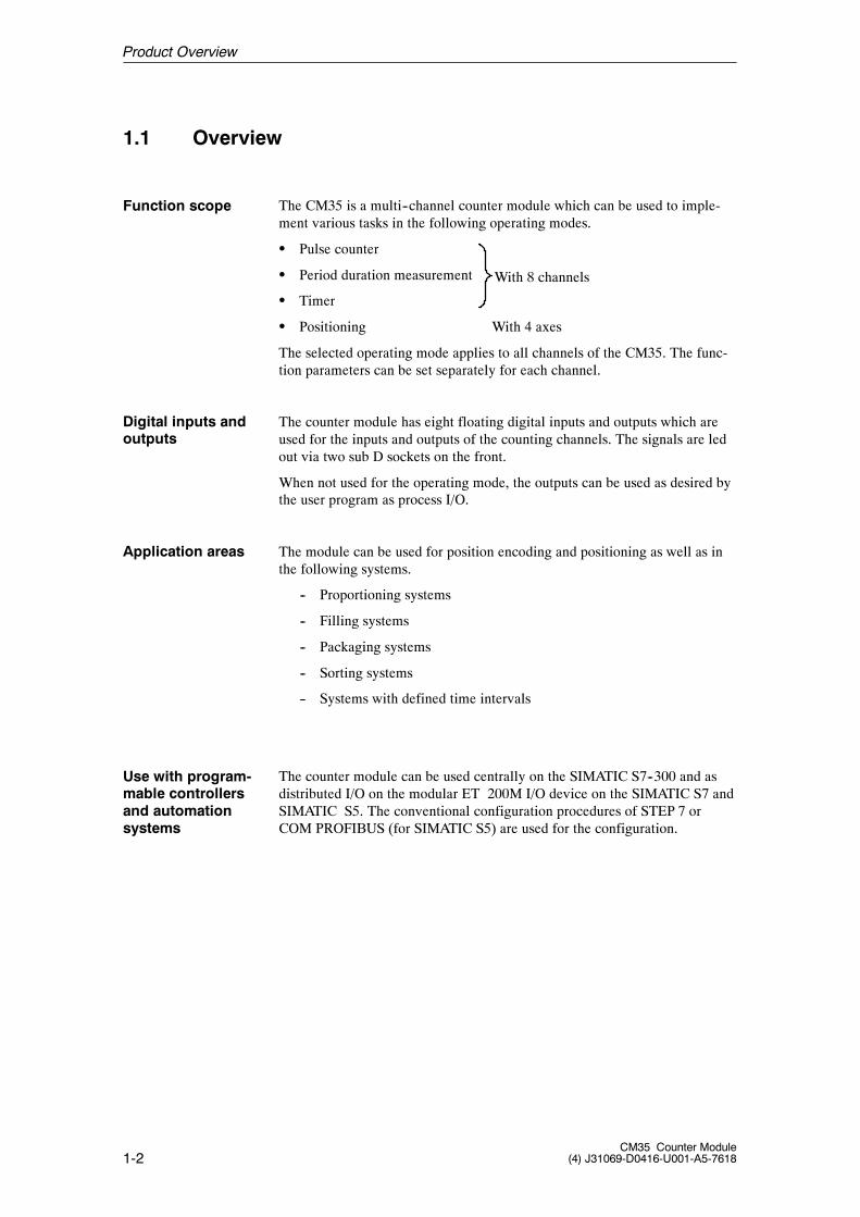
The CM35 is a multi--channel counter module which can be used to imple-ment various tasks in the following operating modes.
S Pulse counter
S Period duration measurement
S Timer
S Positioning With 4 axes
The selected operating mode applies to all channels of the CM35. The func-tion parameters can be set separately for each channel.
The counter module has eight floating digital inputs and outputs which areused for the inputs and outputs of the counting channels. The signals are ledout via two sub D sockets on the front.
When not used for the operating mode, the outputs can be used as desired bythe user program as process I/O.
The module can be used for position encoding and positioning as well as inthe following systems.
-- Proportioning systems
-- Filling systems
-- Packaging systems
-- Sorting systems
-- Systems with defined time intervals
The counter module can be used centrally on the SIMATIC S7--300 and asdistributed I/O on the modular ET 200M I/O device on the SIMATIC S7 andSIMATIC S5. The conventional configuration procedures of STEP 7 orCOM PROFIBUS (for SIMATIC S5) are used for the configuration.
Function scope
Digital inputs andoutputs
Application areas
Use with program-mable controllersand automationsystems
Product Overview
With 8 channels
1-3CM35 Counter Module(4) J31069-D0416-U001-A5-7618
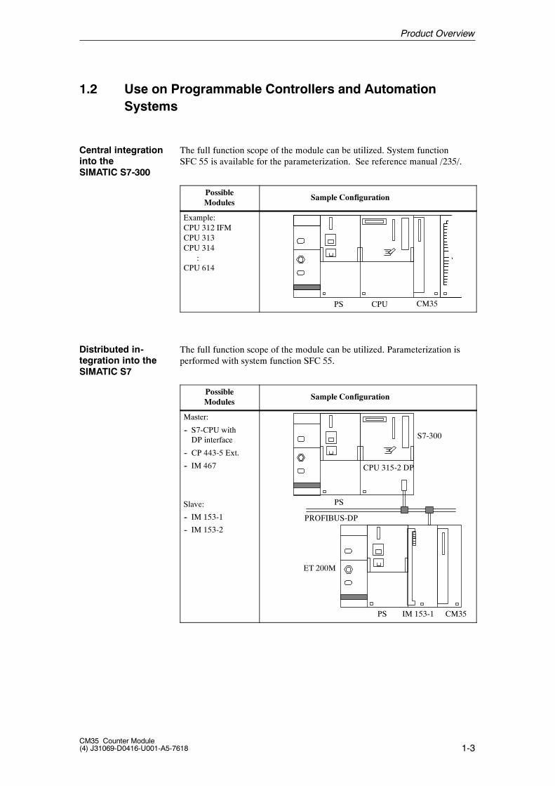
1.2 Use on Programmable Controllers and AutomationSystems
The full function scope of the module can be utilized. System functionSFC 55 is available for the parameterization. See reference manual /235/.
PossibleModules
Sample Configuration
Example:CPU 312 IFMCPU 313CPU 314
:CPU 614
PS CM35CPU
The full function scope of the module can be utilized. Parameterization isperformed with system function SFC 55.
PossibleModules
Sample Configuration
Master:
-- S7-CPU withDP interface
-- CP 443-5 Ext.
-- IM 467
Slave:
-- IM 153-1
-- IM 153-2
PS
CPU 315-2 DP
PS CM35IM 153-1
S7-300
ET 200M
PROFIBUS-DP
Central integrationinto theSIMATIC S7-300
Distributed in-tegration into theSIMATIC S7
Product Overview
1-4CM35 Counter Module
(4) J31069-D0416-U001-A5-7618
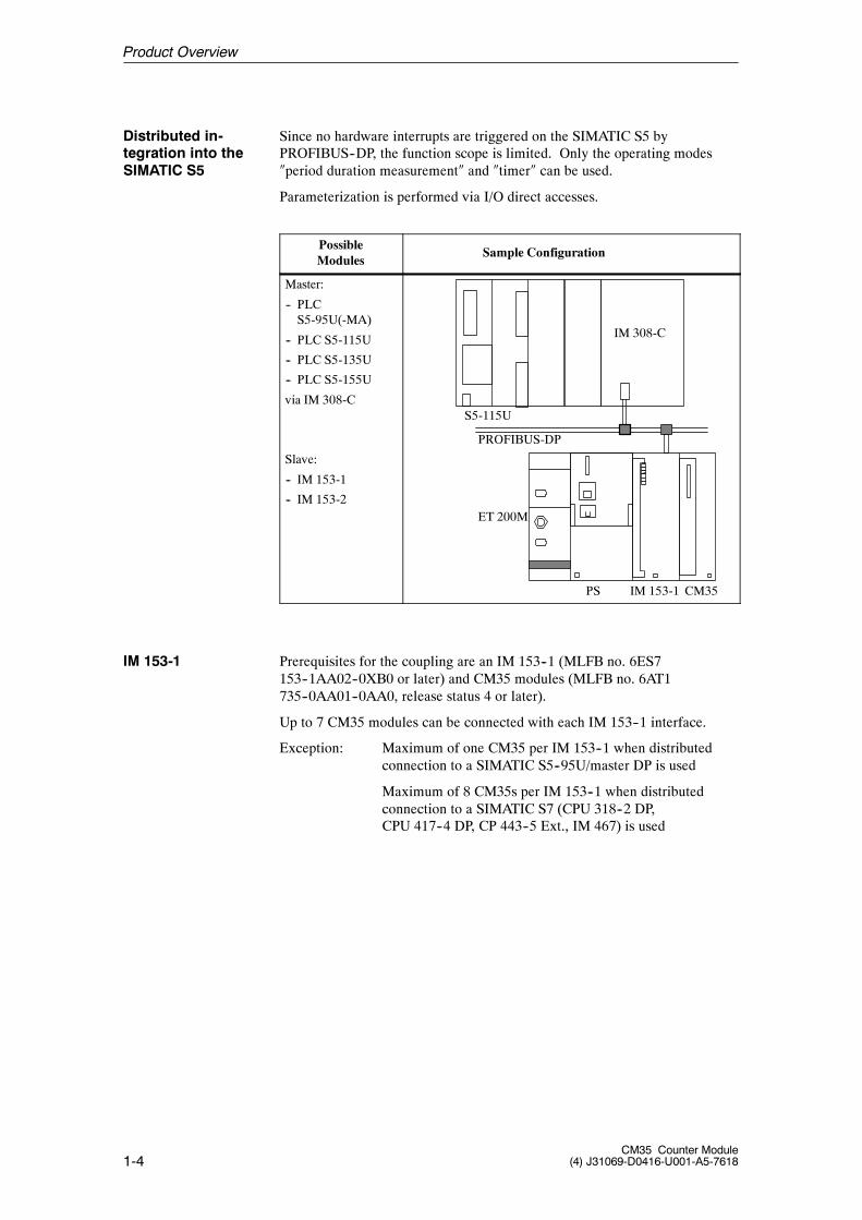
Since no hardware interrupts are triggered on the SIMATIC S5 byPROFIBUS--DP, the function scope is limited. Only the operating modes�period duration measurement� and �timer� can be used.
Parameterization is performed via I/O direct accesses.
PossibleModules
Sample Configuration
Master:
-- PLCS5-95U(-MA)
-- PLC S5-115U
-- PLC S5-135U
-- PLC S5-155U
via IM 308-C
Slave:
-- IM 153-1
-- IM 153-2
PS CM35IM 153-1
ET 200M
PROFIBUS-DP
IM 308-C
S5-115U
Prerequisites for the coupling are an IM 153--1 (MLFB no. 6ES7153--1AA02--0XB0 or later) and CM35 modules (MLFB no. 6AT1735--0AA01--0AA0, release status 4 or later).
Up to 7 CM35 modules can be connected with each IM 153--1 interface.
Exception: Maximum of one CM35 per IM 153--1 when distributedconnection to a SIMATIC S5--95U/master DP is used
Maximum of 8 CM35s per IM 153--1 when distributedconnection to a SIMATIC S7 (CPU 318--2 DP,CPU 417--4 DP, CP 443--5 Ext., IM 467) is used
Distributed in-tegration into theSIMATIC S5
IM 153-1
Product Overview
1-5CM35 Counter Module(4) J31069-D0416-U001-A5-7618
Prerequisites for the coupling are an IM 153--2 (MLFB no. 6ES7153--2AA01--0XB0, release status 2 or later) and CM35 modules (MLFB no.6AT1 735--0AA01--0AA0).
CM35 modules (MLFB no. 6AT1 735--0AA01--0AA0, release status 4 orlater) are required for the IM 153--2 interfaces (MLFB no. 6ES7153--2AA02--0XB0, release status 5 or later).
Up to 7 CM35 modules can be connected to each IM 153--2 interface.
Exception: Maximum of one CM35 per IM 153--2 when distributedconnection to a SIMATIC S5--95U/master DP is used
Maximum of 8 CM35s per IM 153--2 when distributedconnection to a SIMATIC S7 (CPU 318--2 DP,CPU 417--4 DP, CP 443--5 Ext., IM 467) is used.
The present version of the CM35 does not support:
S The setup with active bus modules for ET 200M
S Use on high--availability programmable controllers with redundant setup(SIMATIC S7-400H)
S Use with SIMATIC PCS 7
For additional information, contact the SIMATIC hotline.
IM 153-2
SIMATIC S7-400Hand active back-plane bus,SIMATIC PCS 7
Product Overview
1-6CM35 Counter Module
(4) J31069-D0416-U001-A5-7618
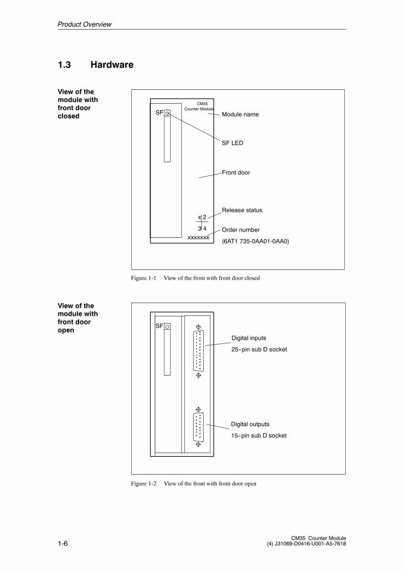
1.3 Hardware
Module name
SF LED
Front door
Release status
Order number
(6AT1 735-0AA01-0AA0)xxxxxxx
x 2
3 4
SF
CM35Counter Module
Figure 1-1 View of the front with front door closed
SF
Digital inputs
25--pin sub D socket
Digital outputs
15--pin sub D socket
Figure 1-2 View of the front with front door open
View of themodule withfront doorclosed
View of themodule withfront dooropen
Product Overview
1-7CM35 Counter Module(4) J31069-D0416-U001-A5-7618
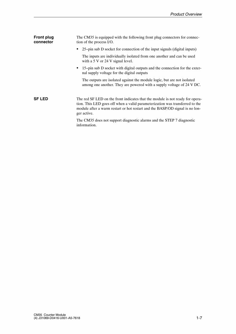
The CM35 is equipped with the following front plug connectors for connec-tion of the process I/O.
S 25--pin sub D socket for connection of the input signals (digital inputs)
The inputs are individually isolated from one another and can be usedwith a 5 V or 24 V signal level.
S 15--pin sub D socket with digital outputs and the connection for the exter-nal supply voltage for the digital outputs
The outputs are isolated against the module logic, but are not isolatedamong one another. They are powered with a supply voltage of 24 V DC.
The red SF LED on the front indicates that the module is not ready for opera-tion. This LED goes off when a valid parameterization was transferred to themodule after a warm restart or hot restart and the BASP/OD signal is no lon-ger active.
The CM35 does not support diagnostic alarms and the STEP 7 diagnosticinformation.
Front plugconnector
SF LED
Product Overview
1-8CM35 Counter Module
(4) J31069-D0416-U001-A5-7618
1.4 Software
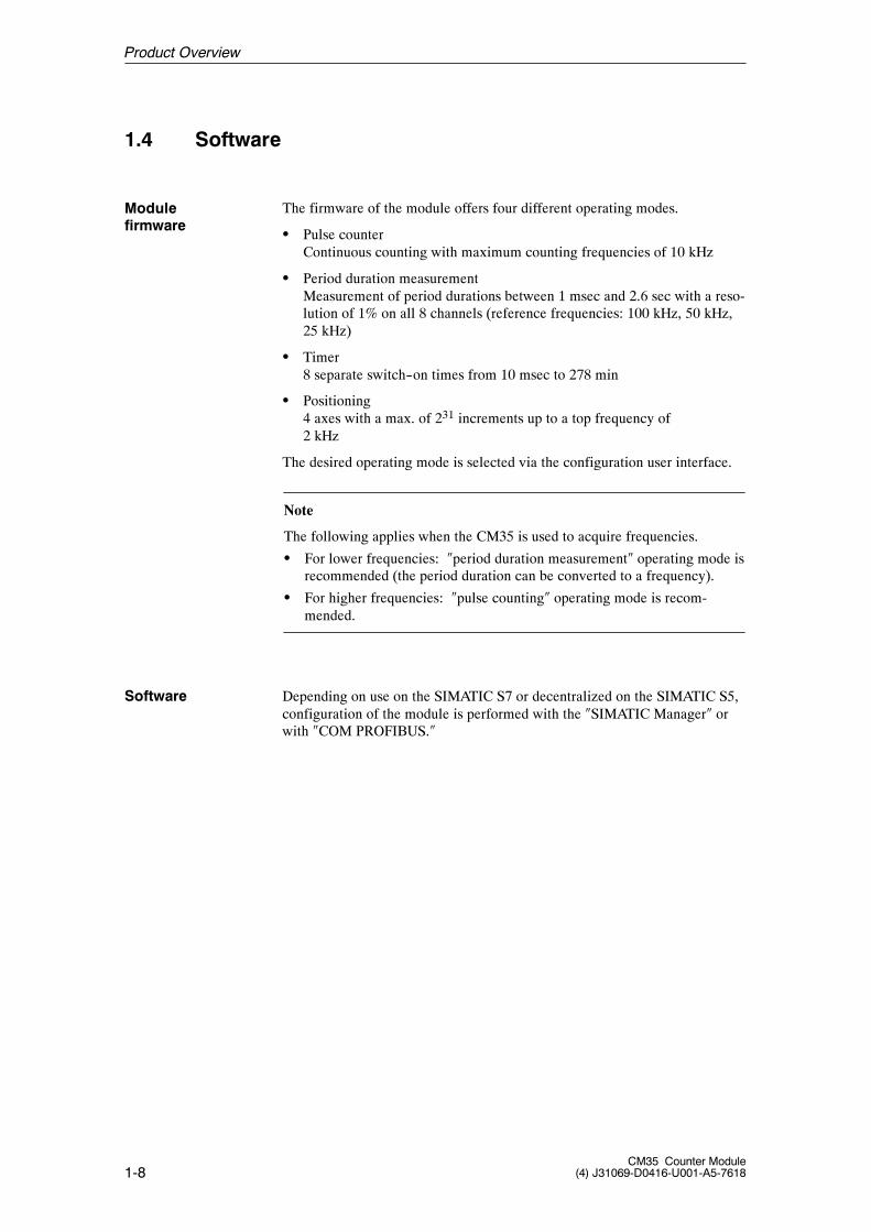
The firmware of the module offers four different operating modes.
S Pulse counterContinuous counting with maximum counting frequencies of 10 kHz
S Period duration measurementMeasurement of period durations between 1 msec and 2.6 sec with a reso-lution of 1% on all 8 channels (reference frequencies: 100 kHz, 50 kHz,25 kHz)
S Timer8 separate switch--on times from 10 msec to 278 min
S Positioning4 axes with a max. of 231 increments up to a top frequency of2 kHz
The desired operating mode is selected via the configuration user interface.
Note
The following applies when the CM35 is used to acquire frequencies.
S For lower frequencies: �period duration measurement� operating mode isrecommended (the period duration can be converted to a frequency).
S For higher frequencies: �pulse counting� operating mode is recom-mended.
Depending on use on the SIMATIC S7 or decentralized on the SIMATIC S5,configuration of the module is performed with the �SIMATIC Manager� orwith �COM PROFIBUS.�
Modulefirmware
Software
Product Overview
1-9CM35 Counter Module(4) J31069-D0416-U001-A5-7618
1.5 Technical Data
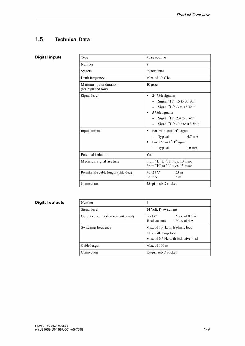
Type Pulse counter
Number 8
System Incremental
Limit frequency Max. of 10 kHz
Minimum pulse duration(for high and low)
40 �sec
Signal level S 24 Volt signals:
-- Signal �H�: 15 to 30 Volt
-- Signal �L�: -3 to +5 Volt
S 5 Volt signals:
-- Signal �H�: 2.4 to 6 Volt
-- Signal �L�: --0.6 to 0.8 Volt
Input current S For 24 V and �H� signal
-- Typical 4.7 mA
S For 5 V and �H� signal
-- Typical 10 mA
Potential isolation Yes
Maximum signal rise time From �L� to �H�: typ. 10 msecFrom �H� to �L�: typ. 15 msec
Permissible cable length (shielded) For 24 V 25 mFor 5 V 5 m
Connection 25--pin sub D socket
Number 8
Signal level 24 Volt, P--switching
Output current (short--circuit proof) Per DO: Max. of 0.5 ATotal current: Max. of 4 A
Switching frequency Max. of 10 Hz with ohmic load
8 Hz with lamp load
Max. of 0.5 Hz with inductive load
Cable length Max. of 100 m
Connection 15--pin sub D socket
Digital inputs
Digital outputs
Product Overview
1-10CM35 Counter Module
(4) J31069-D0416-U001-A5-7618
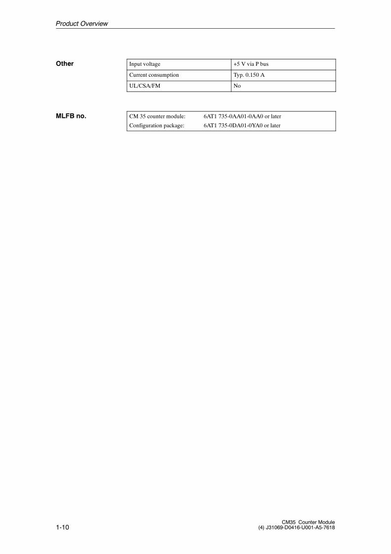
Input voltage +5 V via P bus
Current consumption Typ. 0.150 A
UL/CSA/FM No
CM 35 counter module: 6AT1 735-0AA01-0AA0 or later
Configuration package: 6AT1 735-0DA01-0YA0 or later
Other
MLFB no.
Product Overview

2-1CM35 Counter Module(4) J31069-D0416-U001-A5-7618
Function Description 2
2-2CM35 Counter Module
(4) J31069-D0416-U001-A5-7618
2.1 Function Overview
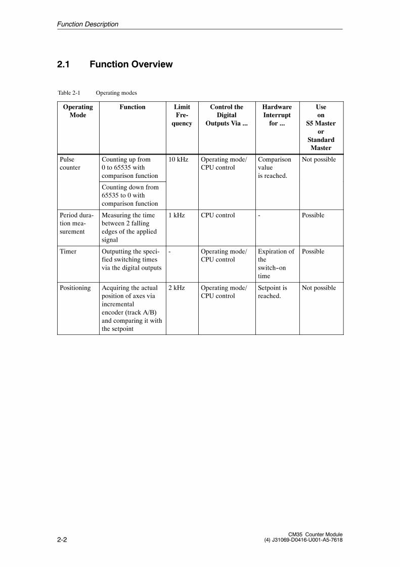
Table 2-1 Operating modes
OperatingMode
Function LimitFre-
quency
Control theDigital
Outputs Via ...
HardwareInterruptfor ...
Useon
S5 Masteror
StandardMaster
Pulsecounter
Counting up from0 to 65535 withcomparison function
10 kHz Operating mode/CPU control
Comparisonvalueis reached.
Not possible
Counting down from65535 to 0 withcomparison function
Period dura-tion mea-surement
Measuring the timebetween 2 fallingedges of the appliedsignal
1 kHz CPU control - Possible
Timer Outputting the speci-fied switching timesvia the digital outputs
- Operating mode/CPU control
Expiration oftheswitch--ontime
Possible
Positioning Acquiring the actualposition of axes viaincrementalencoder (track A/B)and comparing it withthe setpoint
2 kHz Operating mode/CPU control
Setpoint isreached.
Not possible
Function Description
2-3CM35 Counter Module(4) J31069-D0416-U001-A5-7618
2.2 Pulse Counter
In this operating mode, the CM35 continuously counts up or down between 0and 65535 when the counter is enabled.
-- When the counting value reaches the upper counting limit whilecounting up and another pulse arrives, the counting value jumps to thelower counting limit and counts from there without losing a pulse.
-- When the counting value reaches the lower counting limit whilecounting down and another pulse arrives, the counting value jumps tothe upper counting limit and counts from there without losing a pulse.
2.3 Period Duration Measurement
In this operating mode, the CM35 acquires low frequencies with the aid ofperiod duration measurement.
The CM35 measures the exact time between two falling edges of the count-ing signal by counting the pulses of an internal, precision--quartz referencefrequency.
2.4 Timer
In timer operating mode, precisely defined switch--on times of 10 millisec-onds to 278 minutes can be implemented for every digital output.
2.5 Positioning
In this operating mode, the CM35 supports controlled positioning with aswitch--off point.
Position acquisition is performed with an incremental encoder whose pulsesare acquired by the module with the correct sign in the traversing area from–2,147,483,648 to +2,147,483,647.
Two digital outputs are available for each of the four channels. These out-puts are addressed by the CM35 based on the direction.
Function Description

2-4CM35 Counter Module
(4) J31069-D0416-U001-A5-7618
Function Description
3-1CM35 Counter Module(4) J31069-D0416-U001-A5-7618
Commissioning
This chapter provides all the information you will need for commissioning,including mounting, connection, configuration and parameterization.
Adherence to these safety notes is mandatory. Non--adherence will void thewarranty!
!Warning
Unqualified manipulations on the device/system or non--adherence to thewarnings on the cabinet of the device/system can cause severe personal in-jury or property damage. Only qualified personnel may perform work on thisdevice/system.
Note
This device has been developed, manufactured, tested and documented inaccordance with pertinent safety standards. Under normal conditions, thedevice does not endanger property or human health.
!Caution
Commissioning is prohibited until it has been determined that the machine inwhich these components are to be installed meets the regulations of guide-line 89/392/EWG.
General safetynotes
3

3-2CM35 Counter Module
(4) J31069-D0416-U001-A5-7618
Note
The following rules must be adhered to ensure that EU guidelines89/336/EWG have been met.
S The setup guidelines and safety notes in the manuals and supplementarydocumentation must be adhered to for both the programmable controllerand the CM35.
S To achieve maximum EMC immunity, all signal lines to the CM35 mustbe shielded and applied to a grounded shield retainer rail.
S On the CM35, the cable shield may not be applied to the sub D plug con-nector.
Commissioning
3-3CM35 Counter Module(4) J31069-D0416-U001-A5-7618
3.1 Installation of the CM35
3.1.1 Mounting the CM35
Before physical installation is begun, the appropriate safety precautions mustbe taken and the following points complied with or clarified.
S Was the module still in its original packaging?
S Check the delivery for transportation damages.
S Check the delivery for completeness.
If you discover damages or deficiencies, please contactyour SIEMENS representative.
The S7 interface of the CM35 corresponds to the serial I/O bus (P bus) ofthe SIMATIC S7-300.
All slots on the SIMATIC S7 which can be assigned to signal modules (SM)are available to the CM35.
For additional information, see the manual of the SIMATIC S7--300.
The maximum number of CM35 modules which can be installed on SIMA-TIC programmable controllers depends on the following factors.
S Maximum number of modules in the central rack/expansion unit or themodular ET 200M I/O device
S Memory requirements of the S5/S7/C7 CPU
S Maximum permissible current consumption (5 V) from the S7 backplanebus
For information on possible physical setups and how to configure, seemanual /70/.
Horizontal installation is recommended. When vertical installation is used,remember that environmental temperatures are restricted (max. of 40� C).
Preparation
Slot
Physicalsetup
Installationposition
Commissioning
3-4CM35 Counter Module
(4) J31069-D0416-U001-A5-7618
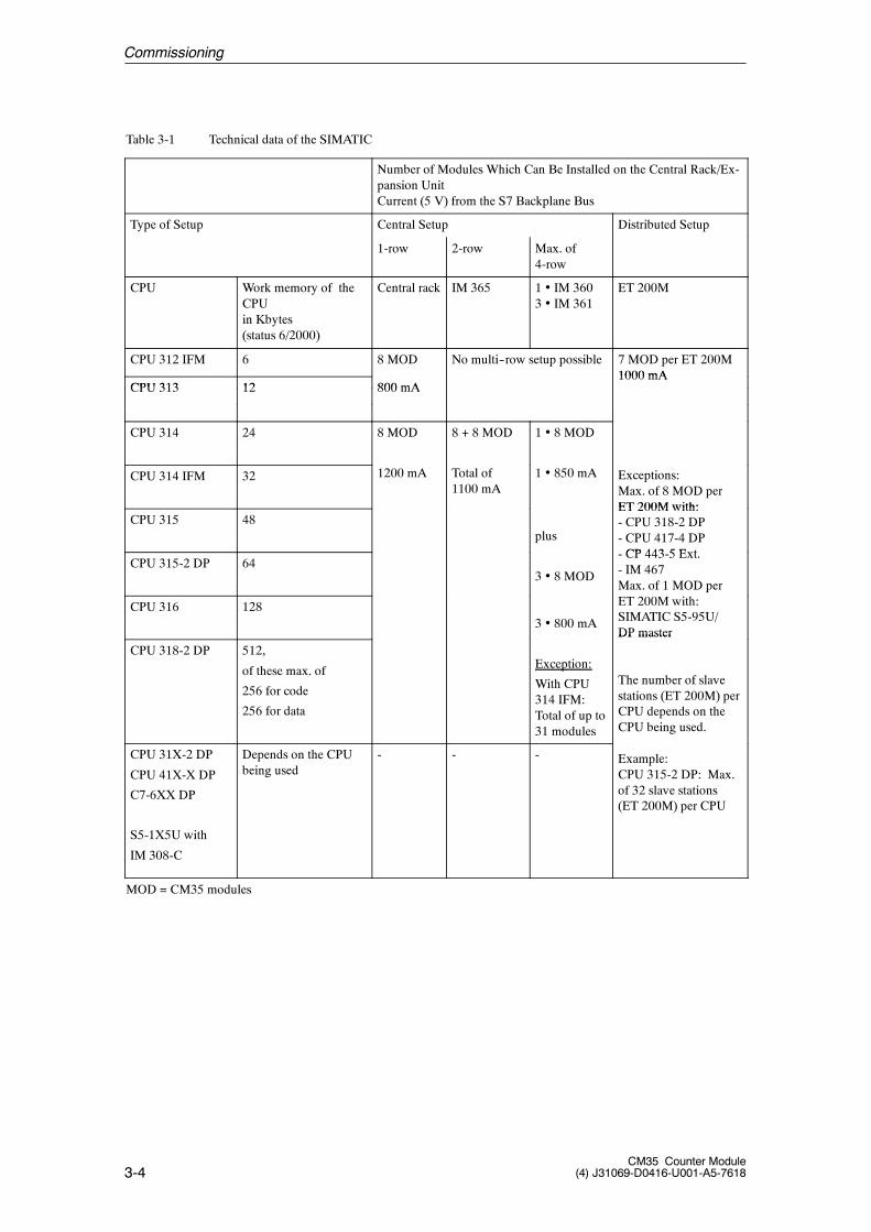
Table 3-1 Technical data of the SIMATIC
Number of Modules Which Can Be Installed on the Central Rack/Ex-pansion UnitCurrent (5 V) from the S7 Backplane Bus
Type of Setup Central Setup Distributed Setup
1-row 2-row Max. of4-row
CPU Work memory of theCPUin Kbytes(status 6/2000)
Central rack IM 365 1 � IM 3603 � IM 361
ET 200M
CPU 312 IFM 6 8 MOD No multi--row setup possible 7 MOD per ET 200M1000 mA
CPU 313 12 800 mA1000 mA
CPU 313 12 800 mA
CPU 314 24 8 MOD 8 + 8 MOD 1 � 8 MOD
CPU 314 IFM 32 1200 mA Total of1100 mA
1 � 850 mA Exceptions:Max. of 8 MOD perET 200M with:
CPU 315 48plus
ET 200M with:- CPU 318-2 DP- CPU 417-4 DPCP 443 5 E t
CPU 315-2 DP 643 � 8 MOD
- CP 443-5 Ext.- IM 467Max. of 1 MOD per
CPU 316 1283 � 800 mA
pET 200M with:SIMATIC S5-95U/DP master
CPU 318-2 DP 512,
of these max. of
256 for code
256 for data
Exception:
With CPU314 IFM:Total of up to31 modules
DP master
The number of slavestations (ET 200M) perCPU depends on theCPU being used.
CPU 31X-2 DP
CPU 41X-X DP
C7-6XX DP
S5-1X5U with
IM 308-C
Depends on the CPUbeing used
- - - Example:CPU 315-2 DP: Max.of 32 slave stations(ET 200M) per CPU
MOD = CM35 modules
Commissioning
3-5CM35 Counter Module(4) J31069-D0416-U001-A5-7618
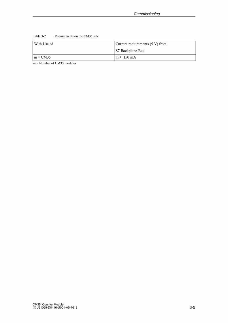
Table 3-2 Requirements on the CM35 side
With Use of Current requirements (5 V) from
S7 Backplane Bus
m � CM35 m � 150 mA
m = Number of CM35 modules
Commissioning
3-6CM35 Counter Module
(4) J31069-D0416-U001-A5-7618
3.1.2 Mounting and Demounting the CM35
No special protective measures (ESD guidelines) are required for installationof the CM35.
You will need a 4.5 mm screwdriver to mount and demount the CM35.
Note
Make absolutely sure that cable installation meets EMC regulations (alsoinside the cabinets).
Avoid installing cables next to power cables, and shield the cables in themanner described above.
Two--sided shield application is usually recommended. When interference isprimarily low--frequency, one--sided shield application can be more advanta-geous.
Adhere to the grounding concept of the SIMATIC S7--300 to avoid problemswith potential.
The setup guidelines (AR) of the SIMATIC S7 (see manual on setting upS7--300 programmable controllers and CPU data) must be adhered to duringall mounting steps, and the following instructions must be performed in theorder specified.
Rules
Required tools
Commissioning
3-7CM35 Counter Module(4) J31069-D0416-U001-A5-7618
For how to mount the modules on the system, see manual /70/ or /140/.A simplified version of installation is given here.
1. Turn off all voltages on the SIMATIC S7, secure against switch--on, andlabel.
2. Make protective conductor connection, or check it. See AR.
3. Mount shield connecting element (SAE).
-- The shield connecting element must be mounted directly under theslot of the CM35 on the mounting rail.
-- Each cable to be connected to the CM35 requires a shield clamp onthe shield rail of the SAE.
4. Plug in bus connector. See AR.
-- A bus connector is supplied with each CM35. Insert the bus connectoron the module occupying the slot to the left of the CM35.
5. Hang in CM35. See AR.
6. Secure CM35 with screw. See AR.
7. Label CM35. See AR.
For how to set up/replace modules in the system, see manual /70/ or /140/.A simplified version of removal is given here.
1. Switch the CPU to STOP.
2. Turn off the power supply.
3. Release the front plug connector, and disconnect it.
4. Release the mounting screw on the module.
5. Swivel the module out of the mounting rail, and remove it.
6. If necessary, install the new module.
For more information on removing the modules, see manuals /70/ and /140/.
How to install
How to remove/replace modules
Commissioning
3-8CM35 Counter Module
(4) J31069-D0416-U001-A5-7618
3.2 Wiring the CM35
The 8 counting inputs (channels) of the CM35 are available on a 25--pin subD socket on the front of the module.Each counting input has separate connections for reference potential(ground), and 5 V and 24 V signals. To prevent malfunctions, only one of thetwo signal voltages may be wired at a time.
The encoder must be powered by an external voltage source.
The 8 outputs of the CM35 are available on a 15--pin sub D socket on thefront of the module. A load power supply of 24 V DC must also be connectedthere which is able to continuously supply the sum of the required outputcurrents.
The outputs are P switches which can handle a load current of 0.4 A. Theyare protected against overload and short circuits.
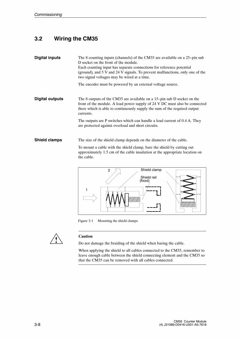
The size of the shield clamp depends on the diameter of the cable.
To mount a cable with the shield clamp, bare the shield by cutting outapproximately 1.5 cm of the cable insulation at the appropriate location onthe cable.
1
2 Shield clamp
Shield rail(fixed)
Figure 3-1 Mounting the shield clamps
!Caution
Do not damage the braiding of the shield when baring the cable.
When applying the shield to all cables connected to the CM35, remember toleave enough cable between the shield connecting element and the CM35 sothat the CM35 can be removed with all cables connected.
Digital inputs
Digital outputs
Shield clamps
Commissioning
3-9CM35 Counter Module(4) J31069-D0416-U001-A5-7618
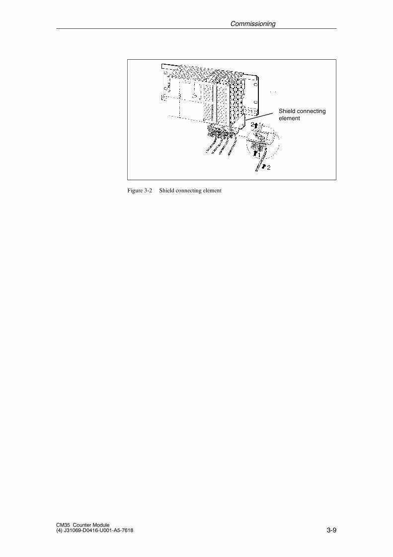
Shield connectingelement
Figure 3-2 Shield connecting element
Commissioning
3-10CM35 Counter Module
(4) J31069-D0416-U001-A5-7618
3.2.1 Connection Allocation of the 25--Pin Sub D Socket
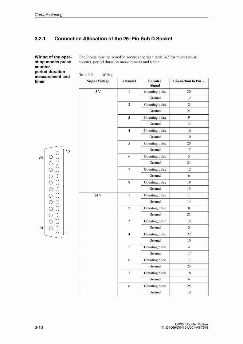
The inputs must be wired in accordance with table 3-3 for modes pulsecounter, period duration measurement and timer.
Table 3-3 Wiring
Signal Voltage Channel EncoderSignal
Connection to Pin ...
5 V 1 Counting pulse 20
Ground 14
2 Counting pulse 2
Ground 21
3 Counting pulse 9
Ground 3
4 Counting pulse 16
Ground 10
5 Counting pulse 23
Ground 17
6 Counting pulse 5
Ground 24
7 Counting pulse 12
Ground 6
8 Counting pulse 19
Ground 13
24 V 1 Counting pulse 1
Ground 14
2 Counting pulse 8
Ground 21
3 Counting pulse 15
Ground 3
4 Counting pulse 22
Ground 10
5 Counting pulse 4
Ground 17
6 Counting pulse 11
Ground 24
7 Counting pulse 18
Ground 6
8 Counting pulse 25
Ground 13
Wiring of the oper-ating modes pulsecounter,period durationmeasurement andtimer
25
13
141
Commissioning
3-11CM35 Counter Module(4) J31069-D0416-U001-A5-7618
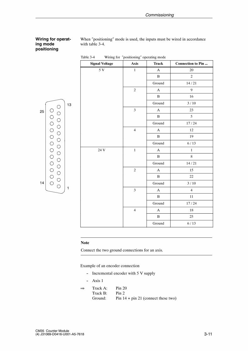
When �positioning� mode is used, the inputs must be wired in accordancewith table 3-4.
Table 3-4 Wiring for �positioning� operating mode
Signal Voltage Axis Track Connection to Pin ...
5 V 1 A 20
B 2
Ground 14 / 21
2 A 9
B 16
Ground 3 / 10
3 A 23
B 5
Ground 17 / 24
4 A 12
B 19
Ground 6 / 13
24 V 1 A 1
B 8
Ground 14 / 21
2 A 15
B 22
Ground 3 / 10
3 A 4
B 11
Ground 17 / 24
4 A 18
B 25
Ground 6 / 13
Note
Connect the two ground connections for an axis.
Example of an encoder connection
-- Incremental encoder with 5 V supply
-- Axis 1
� Track A: Pin 20Track B: Pin 2Ground: Pin 14 + pin 21 (connect these two)
Wiring for operat-ing modepositioning
25
13
141
Commissioning
3-12CM35 Counter Module
(4) J31069-D0416-U001-A5-7618
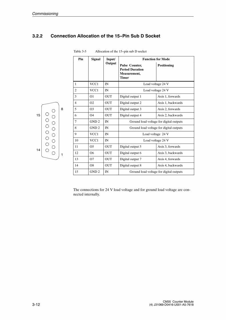
3.2.2 Connection Allocation of the 15--Pin Sub D Socket
Table 3-5 Allocation of the 15--pin sub D socket
Pin Signal Input/O t t
Function for ModeOutput
Pulse Counter,Period DurationMeasurement,Timer
Positioning
1 VCC1 IN Load voltage 24 V
2 VCC1 IN Load voltage 24 V
3 O1 OUT Digital output 1 Axis 1, forwards
4 O2 OUT Digital output 2 Axis 1, backwards
5 O3 OUT Digital output 3 Axis 2, forwards
6 O4 OUT Digital output 4 Axis 2, backwards
7 GND 2 IN Ground load voltage for digital outputs
8 GND 2 IN Ground load voltage for digital outputs
9 VCC1 IN Load voltage 24 V
10 VCC1 IN Load voltage 24 V
11 O5 OUT Digital output 5 Axis 3, forwards
12 O6 OUT Digital output 6 Axis 3, backwards
13 O7 OUT Digital output 7 Axis 4, forwards
14 O8 OUT Digital output 8 Axis 4, backwards
15 GND 2 IN Ground load voltage for digital outputs
The connections for 24 V load voltage and for ground load voltage are con-nected internally.
15
8
141
Commissioning
3-13CM35 Counter Module(4) J31069-D0416-U001-A5-7618
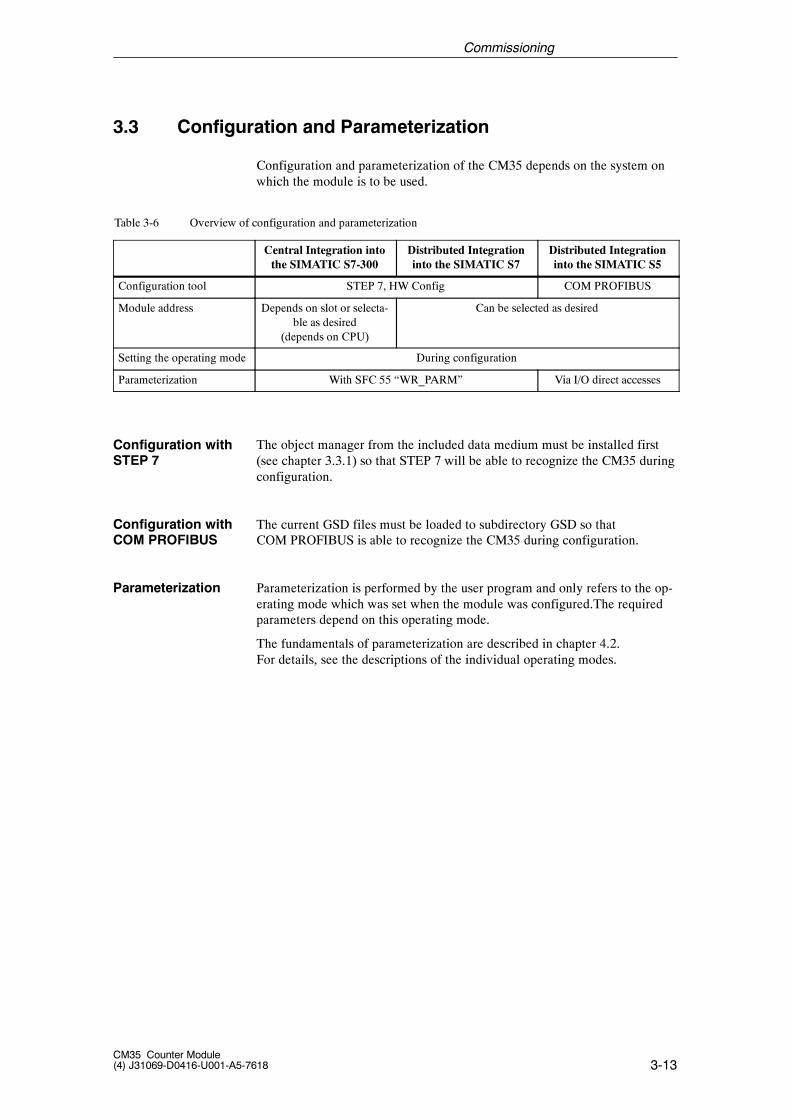
3.3 Configuration and Parameterization
Configuration and parameterization of the CM35 depends on the system onwhich the module is to be used.
Table 3-6 Overview of configuration and parameterization
Central Integration intothe SIMATIC S7-300
Distributed Integrationinto the SIMATIC S7
Distributed Integrationinto the SIMATIC S5
Configuration tool STEP 7, HW Config COM PROFIBUS
Module address Depends on slot or selecta-ble as desired
(depends on CPU)
Can be selected as desired
Setting the operating mode During configuration
Parameterization With SFC 55 “WR_PARM” Via I/O direct accesses
The object manager from the included data medium must be installed first(see chapter 3.3.1) so that STEP 7 will be able to recognize the CM35 duringconfiguration.
The current GSD files must be loaded to subdirectory GSD so thatCOM PROFIBUS is able to recognize the CM35 during configuration.
Parameterization is performed by the user program and only refers to the op-erating mode which was set when the module was configured.The requiredparameters depend on this operating mode.
The fundamentals of parameterization are described in chapter 4.2.For details, see the descriptions of the individual operating modes.
Configuration withSTEP 7
Configuration withCOM PROFIBUS
Parameterization
Commissioning
3-14CM35 Counter Module
(4) J31069-D0416-U001-A5-7618
3.3.1 Installation of the Object Manager for STEP 7
To install the object manager (OM), STEP 7 (starting with V3.2) must beinstalled correctly on your PG/PC.
To install the object manager, proceed as shown below.
1. Make sure that no applications are open in Windows.
2. Insert the data medium.
3. Call the SETUP.EXE program.
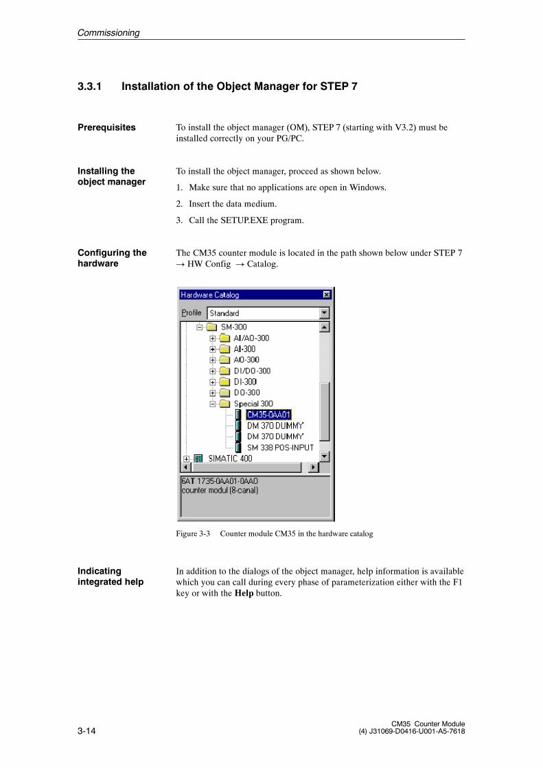
The CM35 counter module is located in the path shown below under STEP 7! HW Config ! Catalog.
Figure 3-3 Counter module CM35 in the hardware catalog
In addition to the dialogs of the object manager, help information is availablewhich you can call during every phase of parameterization either with the F1key or with the Help button.
Prerequisites
Installing theobject manager
Configuring thehardware
Indicatingintegrated help
Commissioning
3-15CM35 Counter Module(4) J31069-D0416-U001-A5-7618
3.3.2 Central Integration into the SIMATIC S7-300
When used with an S7--300, the module is configured with STEP 7 with theapplication HW Config. To add a CM35 to an existing project, proceed asshown below.
1. Start the SIMATIC Manager, and open the desired project.
2. In the left--hand portion of the project screen, select the SIMATIC 300station to which you want to add the CM35.
3. Select the menu command Edit > Open Object.
This opens the HW Config application. This application contains a screenwith the hardware setup of the opened station.
4. Select the CM35 from the module catalog of HW Config, and place it inthe module rack.
Based on its position on the mounting rail, the required input and output ad-dress areas are automatically assigned to the CM35 and entered in the config-uration table.
When certain CPUs are used, these address areas can be changed. For de-tails, see manual /70/.
The operating mode of the CM35 must have already been set during the con-figuration. Proceed as shown below.
1. In the configuration table, select the line with the CM35, and select themenu command Edit > Object Properties.
2. In the dialog box, open the tab Operating Mode, select the desired oper-ating mode, and confirm with OK.
For additional details on preparation for operation, see manual /70/ and usermanual /231/.
Configuration
Moduleaddress
Setting theoperating mode
Commissioning
Commissioning
3-16CM35 Counter Module
(4) J31069-D0416-U001-A5-7618
3.3.3 Distributed Integration into the SIMATIC S7
The module is configured as distributed I/O with the HW Config applicationof STEP 7. To add a CM35 to an existing project, proceed as shown below.
1. Start the SIMATIC Manager, and open the desired project.
2. In the left--hand portion of the project screen, select the SIMATIC stationfrom which the DP slave is to be addressed.
3. Select the menu command Edit > Open Object.
This opens the HW Config application. This application contains a screenwith the hardware setup of the opened station.
4. If not already done, set up a DP slave. From the �Hardware Catalog�screen, select an ET 200M with IM 153-2, and place it in a PROFI-BUS--DP master system.
5. Select the CM35 from the hardware catalog, and place it in the ET 200M.
Based on the position on ET 200M, the required input and output addressareas are automatically assigned to the CM35 and entered in the configura-tion table. Address gaps in the address areas of the CPU rack are utilized.
The preset address areas can be changed in accordance with certain rules.For more information on free address assignment, see manual /70/. Proceedas shown below.
1. In the configuration table, select the line with the CM35, and select themenu command Edit > Object Properties.
2. In the indicated dialog box, open the tab Addresses, and enter the desiredstart address.
If there are address overlaps with other modules, you will be told thiswhen you close the dialog box.
3. Leave the dialog box open so that you can make the following settings ofthe module’s operating mode.
The operating mode of the CM35 must have already been set during configu-ration. Proceed as shown below.
1. If not already done, select the line with the CM35 in the configurationtable, and select the menu command Edit > Object Properties.
2. In the dialog screen, open the tab Operating Mode, select the desiredoperating mode, and confirm with OK.
For additional preparations before operation, see manual /70/ and usermanual /231/.
Configuration
Moduleaddress
Setting theoperating mode
Commissioning
Commissioning
3-17CM35 Counter Module(4) J31069-D0416-U001-A5-7618
3.3.4 Distributed Integration into the SIMATIC S5
Note
This section assumes that you have a knowledge of SIMATIC S5 andCOM PROFIBUS.
The CM35 module can be linked as distributed I/O to the SIMATIC S5 usingPROFIBUS--DP.
The modular ET 200M I/O device is required to link the CM35 modules toPROFIBUS--DP. The SIMATIC S5 is connected to PROFIBUS--DP with in-terface IM 308--C. Another method is to use a SIMATIC S5--95U/DP masterwith integrated PROFIBUS--DP interface.
3.3.4.1 Hardware Prerequisites
Release 4 or later
Note
An FB 192 with release 3 can only be used with an IM 308--C starting withrelease 6!
When release status 2 of the FB 192 is used, all versions of the IM 308-Ccan be used starting with release status 3.
Release 2 or later
The maximum transmission speed is 9600 Kbaud to 1.5 Mbaud, dependingon the length of the cable.
Prerequisites for the coupling are an IM 153--1 (MLFB no. 6ES7153--1AA02--0XB0 or later) and CM35 modules (MLFB no. 6AT1735--0AA01--0AA0, release status 4 or later)
Prerequisites for the coupling are an IM 153--2 (MLFB no. 6ES7153--2AA01--0XB0, release status 2 or later) and CM35 modules (MLFB no.6AT1 735--0AA01--0AA0).
CM35 modules (MLFB no. 6AT1 735--0AA01--0AA0, release status 4 orlater) are required for the IM 153--2 interfaces (MLFB no. 6ES7153--2AA02--0XB0, release status 5 or later).
Integration on theSIMATIC S5
IM 308-C
S5-95U/master DP
IM 153-1
IM 153-2
Commissioning
3-18CM35 Counter Module
(4) J31069-D0416-U001-A5-7618
3.3.4.2 Configuration
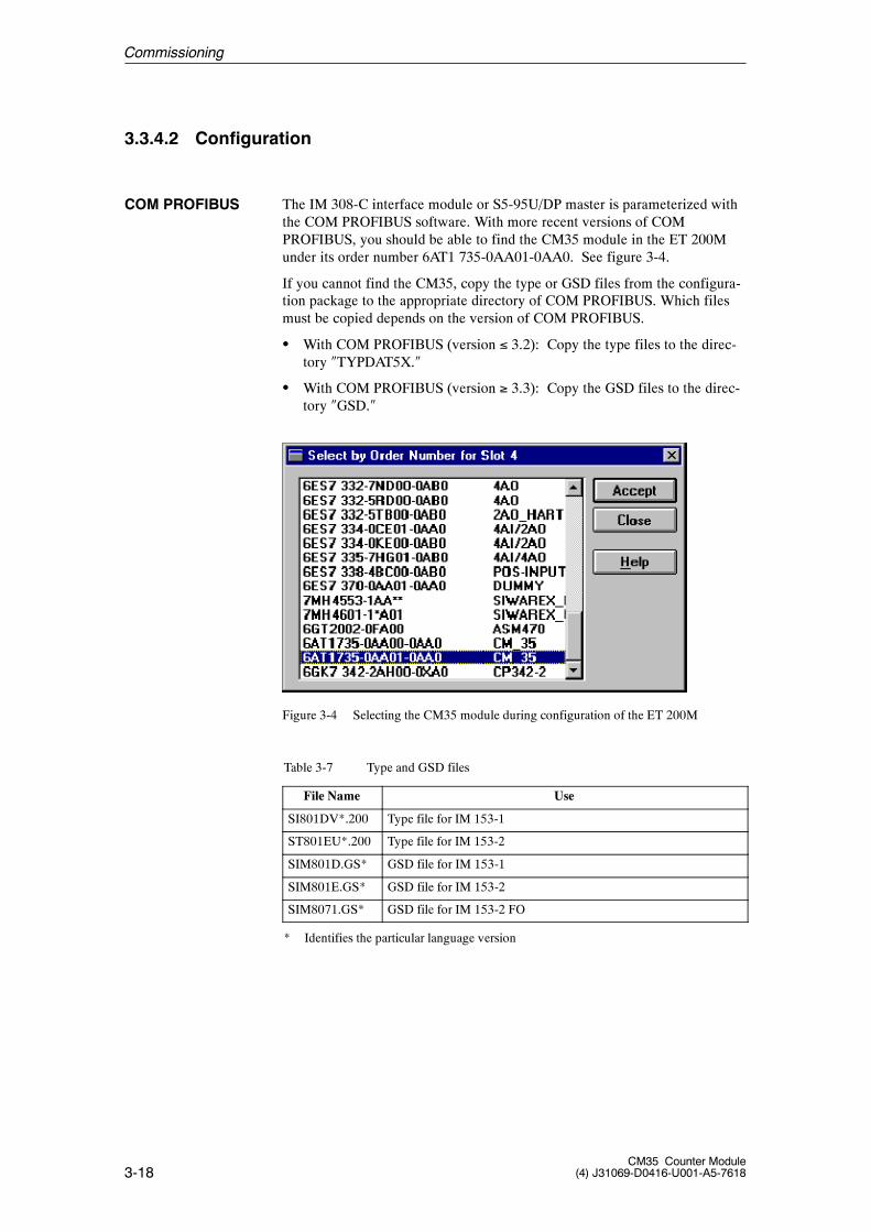
The IM 308-C interface module or S5-95U/DP master is parameterized withthe COM PROFIBUS software. With more recent versions of COMPROFIBUS, you should be able to find the CM35 module in the ET 200Munder its order number 6AT1 735-0AA01-0AA0. See figure 3-4.
If you cannot find the CM35, copy the type or GSD files from the configura-tion package to the appropriate directory of COM PROFIBUS. Which filesmust be copied depends on the version of COM PROFIBUS.
S With COM PROFIBUS (version � 3.2): Copy the type files to the direc-tory �TYPDAT5X.�
S With COM PROFIBUS (version � 3.3): Copy the GSD files to the direc-tory �GSD.�
Figure 3-4 Selecting the CM35 module during configuration of the ET 200M
Table 3-7 Type and GSD files
File Name Use
SI801DV*.200 Type file for IM 153-1
ST801EU*.200 Type file for IM 153-2
SIM801D.GS* GSD file for IM 153-1
SIM801E.GS* GSD file for IM 153-2
SIM8071.GS* GSD file for IM 153-2 FO
* Identifies the particular language version
COM PROFIBUS
Commissioning
3-19CM35 Counter Module(4) J31069-D0416-U001-A5-7618
Note
The latest GSD files (only for COM PROFIBUS version � 3.3) can be down-loaded from the Internet (SIMATIC Customer Support).
Internet address: http://www.ad.siemens.de/support/html_00/index.shtml
Copy the new GSD files to the �GSD� directory, and execute the menu com-mand �File > Open GSD File.�
Using the GSD files included with the configuration package has a drawback-- you will not be using the latest GSD file (e.g., you may not be able to findother new modules).
The type files are only required for older COM PROFIBUSversions � 3.2. In the future, they will be completely replaced by theGSD files.
The module is configured as distributed I/O on the SIMATIC S5 withCOM PROFIBUS.
To add a CM35 to an existing DP master system, proceed as shown below.
1. Start COM PROFIBUS, and open the desired master system.
2. Open a DP slave (ET 200M with IM 153-1), or set up a new one.
3. Place the module in the ET 200M. In the configuration table, select thedesired slot, and select the button Order No. ...In the dialog box �Select...,� select the order number of the CM35(6AT1 735-0AA01-0AA0), and select the Accept button.
4. Leave the configuration table open to set the addresses and operatingmode which come next.
You can specify a start address for the input and for the output area. This ad-dress depends on the operating mode you want to use.
S Direct process inputs and outputs: Addresses in the P or Q areaAccesses only permitted via word load and transfer operations
S Accesses via FB 192: No address specifications requiredFor a detailed description of FB 192 and its manual, see the manual ofCOM PROFIBUS.
Address overlapping with other modules or conflicts with reserved areas areindicated by COM PROFIBUS.
Configuration
Moduleaddress
Commissioning
3-20CM35 Counter Module
(4) J31069-D0416-U001-A5-7618
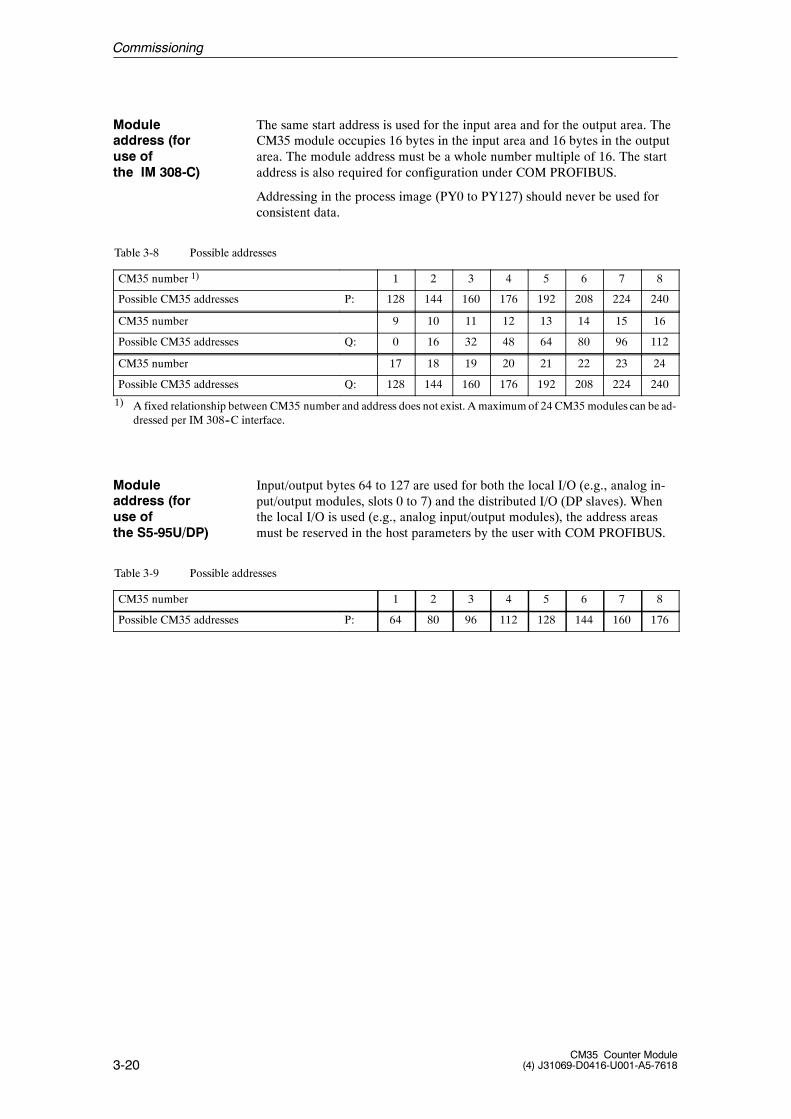
The same start address is used for the input area and for the output area. TheCM35 module occupies 16 bytes in the input area and 16 bytes in the outputarea. The module address must be a whole number multiple of 16. The startaddress is also required for configuration under COM PROFIBUS.
Addressing in the process image (PY0 to PY127) should never be used forconsistent data.
Table 3-8 Possible addresses
CM35 number 1) 1 2 3 4 5 6 7 8
Possible CM35 addresses P: 128 144 160 176 192 208 224 240
CM35 number 9 10 11 12 13 14 15 16
Possible CM35 addresses Q: 0 16 32 48 64 80 96 112
CM35 number 17 18 19 20 21 22 23 24
Possible CM35 addresses Q: 128 144 160 176 192 208 224 240
1) A fixed relationship between CM35 number and address does not exist. A maximumof 24 CM35 modules can be ad-dressed per IM 308--C interface.
Input/output bytes 64 to 127 are used for both the local I/O (e.g., analog in-put/output modules, slots 0 to 7) and the distributed I/O (DP slaves). Whenthe local I/O is used (e.g., analog input/output modules), the address areasmust be reserved in the host parameters by the user with COM PROFIBUS.
Table 3-9 Possible addresses
CM35 number 1 2 3 4 5 6 7 8
Possible CM35 addresses P: 64 80 96 112 128 144 160 176
Moduleaddress (foruse ofthe IM 308-C)
Moduleaddress (foruse ofthe S5-95U/DP)
Commissioning
3-21CM35 Counter Module(4) J31069-D0416-U001-A5-7618
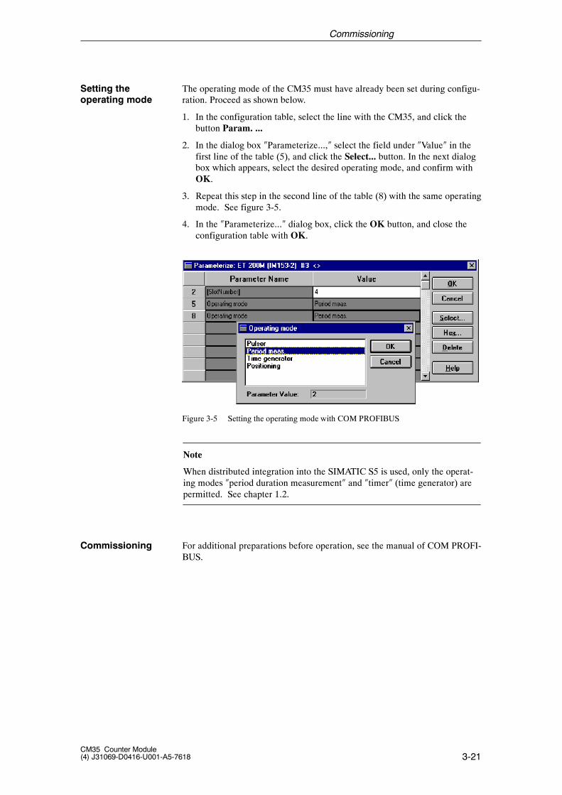
The operating mode of the CM35 must have already been set during configu-ration. Proceed as shown below.
1. In the configuration table, select the line with the CM35, and click thebutton Param. ...
2. In the dialog box �Parameterize...,� select the field under �Value� in thefirst line of the table (5), and click the Select... button. In the next dialogbox which appears, select the desired operating mode, and confirm withOK.
3. Repeat this step in the second line of the table (8) with the same operatingmode. See figure 3-5.
4. In the �Parameterize...� dialog box, click the OK button, and close theconfiguration table with OK.
Figure 3-5 Setting the operating mode with COM PROFIBUS
Note
When distributed integration into the SIMATIC S5 is used, only the operat-ing modes �period duration measurement� and �timer� (time generator) arepermitted. See chapter 1.2.
For additional preparations before operation, see the manual of COM PROFI-BUS.
Setting theoperating mode
Commissioning
Commissioning
3-22CM35 Counter Module
(4) J31069-D0416-U001-A5-7618
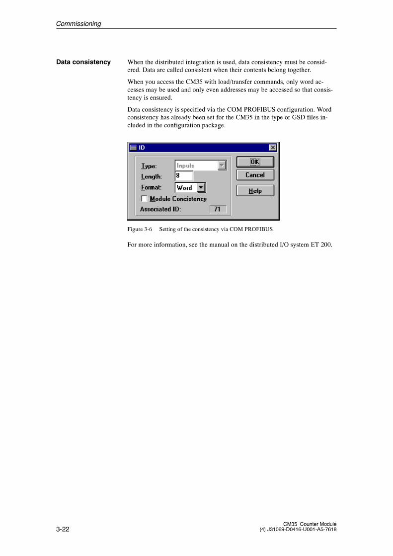
When the distributed integration is used, data consistency must be consid-ered. Data are called consistent when their contents belong together.
When you access the CM35 with load/transfer commands, only word ac-cesses may be used and only even addresses may be accessed so that consis-tency is ensured.
Data consistency is specified via the COM PROFIBUS configuration. Wordconsistency has already been set for the CM35 in the type or GSD files in-cluded in the configuration package.
Figure 3-6 Setting of the consistency via COM PROFIBUS
For more information, see the manual on the distributed I/O system ET 200.
Data consistency
Commissioning
3-23CM35 Counter Module(4) J31069-D0416-U001-A5-7618
3.4 Reactions during Startup and in Case of Errors
When a warm restart (power on) takes place, the red group error LED (SF)on the front of the module stays on until the module is ready for operation(i.e., until it has received valid parameters).
When the module firmware recognizes the CPU STOP state, the parametersstored on the CM35 lose their validity. Parameter memory and the input andoutput area are deleted. This is indicated by the group error LED.
When the CPU assumes the STOP state, running operation of the CM35 isterminated. The digital outputs are switched off (i.e., reset). Although theoperating mode is retained, the parameters are no longer valid.
Since the CM35 is completely powered by the backplane bus of theSIMATIC S7-300, it has to be switched on together with the S7--300 CPU orIM module.
Warm restart
Hot restart
Reaction to failureof the S7-300
Module powersupply
Commissioning

3-24CM35 Counter Module
(4) J31069-D0416-U001-A5-7618
Commissioning

4-1CM35 Counter Module(4) J31069-D0416-U001-A5-7618
Data Communication with the CM35 4
4-2CM35 Counter Module
(4) J31069-D0416-U001-A5-7618
4.1 Overview
The CM35 is located in the analog address area of the programmable control-ler.
Central operation:
The address is assigned in one of the following ways, depending on theS7--300 CPU being used.
-- Slot--oriented
-- As desired
Use the module’s start address from HW Config.
Distributed operation:
The address of the CM35 can be assigned as desired.
The start address of the module can be taken from one of the following.
-- HW Config with an S7 master (e.g., CPU 315--2 DP)
-- COM PROFIBUS with an S5 master (e.g., IM 308-C).
Use HW Config or COM PROFIBUS to set the operating mode for theCM35 (e.g., pulse counter).
The data required to operate the module in the selected mode (e.g., countingdirection and comparison values for pulse counting mode) are transferred tothe CM35 with the parameterization.
The parameters must be transferred at least once to the CM35 after CPUSTOP� RUN.
With centralized use of the CM35 and with distributed use on S7 masters, theparameters are written with system function SFC 55 “WR_PARM.”
With DP use with S5 masters, the parameters are written with direct I/O ac-cesses (only in the permissible modes �period duration measurement� and�timer.�
After parameterization, you can
-- control operation of the individual channels via write accesses
-- read the data of the CM35 with read accesses
Depending on the selected operating mode and the parameterization, themodule supports the triggering of hardware interrupts with the SIMATIC S7.OB 40 must be programmed for this.
Address area
Parameterization
Programming
Data Communication with the CM35
4-3CM35 Counter Module(4) J31069-D0416-U001-A5-7618
4.2 Parameterization
The parameter data for the individual operating modes are combined intoparameter blocks. The required number of parameter blocks depends on theoperating mode which you selected.
The parameters must be transferred at least once to the CM35 after CPUSTOP� RUN. After the data have been transferred correctly, the red SFLED goes off and the module is ready for operation.
The parameters can be specified again during operation so that the individualchannels can be adjusted to the particular state of the process.
The parameter blocks can be transferred in any sequence. The order has noeffect on their use.
Note
Before a channel can be reparameterized, it must be stopped. The parametersfor a channel may not be changed or written while the channel is running.
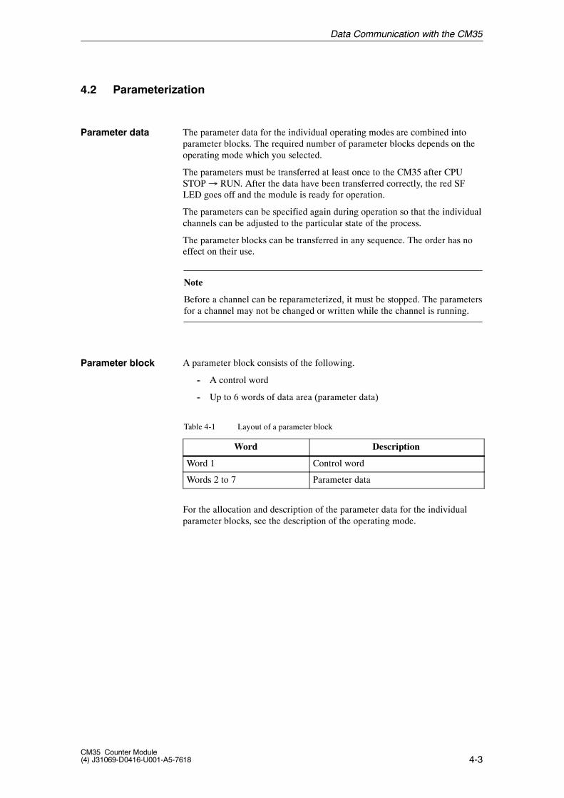
A parameter block consists of the following.
-- A control word
-- Up to 6 words of data area (parameter data)
Table 4-1 Layout of a parameter block
Word Description
Word 1 Control word
Words 2 to 7 Parameter data
For the allocation and description of the parameter data for the individualparameter blocks, see the description of the operating mode.
Parameter data
Parameter block
Data Communication with the CM35
4-4CM35 Counter Module
(4) J31069-D0416-U001-A5-7618
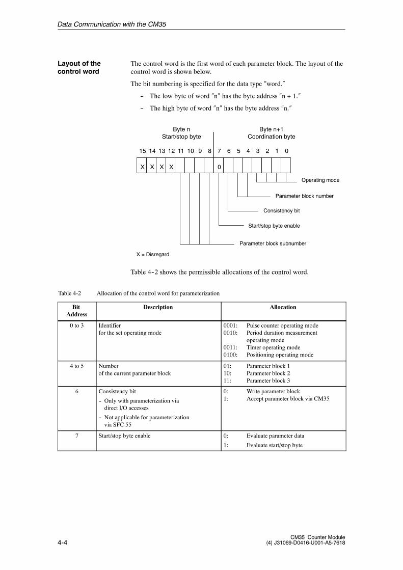
The control word is the first word of each parameter block. The layout of thecontrol word is shown below.
The bit numbering is specified for the data type �word.�
-- The low byte of word �n� has the byte address �n + 1.�
-- The high byte of word �n� has the byte address �n.�
15
X
14
X
13
X
12
X
11 10 9 8 7
0
6 5 4 3 2 1 0
Byte nStart/stop byte
Byte n+1Coordination byte
Operating mode
Start/stop byte enable
Parameter block number
Consistency bit
Parameter block subnumber
X = Disregard
Table 4--2 shows the permissible allocations of the control word.
Table 4-2 Allocation of the control word for parameterization
BitAddress
Description Allocation
0 to 3 Identifierfor the set operating mode
0001: Pulse counter operating mode0010: Period duration measurement
operating mode0011: Timer operating mode0100: Positioning operating mode
4 to 5 Numberof the current parameter block
01: Parameter block 110: Parameter block 211: Parameter block 3
6 Consistency bit
-- Only with parameterization viadirect I/O accesses
-- Not applicable for parameterizationvia SFC 55
0: Write parameter block1: Accept parameter block via CM35
7 Start/stop byte enable 0: Evaluate parameter data
1: Evaluate start/stop byte
Layout of thecontrol word
Data Communication with the CM35
4-5CM35 Counter Module(4) J31069-D0416-U001-A5-7618
Table 4-2 Allocation of the control word for parameterization, continued
BitAddress
AllocationDescription
8 to 11 Subnumber for parameter block
-- Only for �positioning� mode
-- Not applicable to the operating modespulse counter, period duration measurementand timer
0000: Parameter subblock 00001: Parameter subblock 1 (axis 1)0010: Parameter subblock 2 (axis 2)0011: Parameter subblock 3 (axis 3)0100: Parameter subblock 4 (axis 4)
12 to 15 Disregard
�Timer� mode/parameterization via direct I/O accessesWrite parameter block 2:To write data assign W#16#0023 to control wordTo accept data via CM35 assign W#16#0063 to control word
The parameter blocks for the parameterization of the CM35 can be written inone of the following ways.
-- Use of data record number 1 with SFC 55 “WR_PARM”
-- Write the analog I/O address area with direct I/O accesses
The data are written with SFC 55 when the CM35 is used with SIMATIC S7.
Direct I/O write--accesses to the data must be used for DP operation with S5masters or standard DP masters. A consistency bit which must be specifiedvia the user program is available to ensure the data consistency of a parame-ter block.
Example (S5)
Data transmission
Data Communication with the CM35
4-6CM35 Counter Module
(4) J31069-D0416-U001-A5-7618
4.2.1 Parameterization with SFC 55 (Only SIMATIC S7)
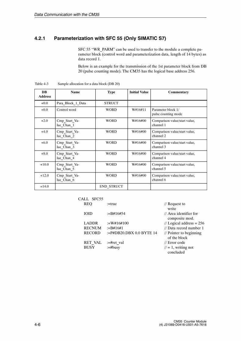
SFC 55 “WR_PARM” can be used to transfer to the module a complete pa-rameter block (control word and parameterization data, length of 14 bytes) asdata record 1.
Below is an example for the transmission of the 1st parameter block from DB20 (pulse counting mode). The CM35 has the logical base address 256.
Table 4-3 Sample allocation for a data block (DB 20)
DBAddress
Name Type Initial Value Commentary
+0.0 Para_Block_1_Data STRUCT
+0.0 Control word WORD W#16#11 Parameter block 1/pulse counting mode
+2.0 Cmp_Start_Va-lue_Chan_1
WORD W#16#00 Comparison value/start value,channel 1
+4.0 Cmp_Start_Va-lue_Chan_2
WORD W#16#00 Comparison value/start value,channel 2
+6.0 Cmp_Start_Va-lue_Chan_3
WORD W#16#00 Comparison value/start value,channel 3
+8.0 Cmp_Start_Va-lue_Chan_4
WORD W#16#00 Comparison value/start value,channel 4
+10.0 Cmp_Start_Va-lue_Chan_5
WORD W#16#00 Comparison value/start value,channel 5
+12.0 Cmp_Start_Va-lue_Chan_6
WORD W#16#00 Comparison value/start value,channel 6
=14.0 END_STRUCT
CALL SFC55REQ :=true // Request to
writeIOID :=B#16#54 // Area identifier for
composite mod.LADDR :=W#16#100 // Logical address = 256RECNUM :=B#16#1 // Data record number 1RECORD :=P#DB20.DBX 0.0 BYTE 14 // Pointer to beginning
of the blockRET_VAL :=#ret_val // Error codeBUSY :=#busy // = 1, writing not
concluded
Data Communication with the CM35
4-7CM35 Counter Module(4) J31069-D0416-U001-A5-7618
SFC 55 must continue to be called until BUSY is reset.
SFC 55 should not be used in OB100. We recommend setting a flag bit(startup identifier) in OB100 instead. SFC 55 should then be called based onthis flag bit to parameterize the CM35 after the automation system is turnedon.
If an error occurs while the function is being processed, the error code is indi-cated in parameter RET_VAL, and BIE is set to �0.�
For a description of the parameterization of the system functions and the re-turn values, see STEP 7 reference manual /235/.
Data Communication with the CM35
4-8CM35 Counter Module
(4) J31069-D0416-U001-A5-7618
4.2.2 Parameterization via Direct I/O Accesses (Only SIMATIC S5)
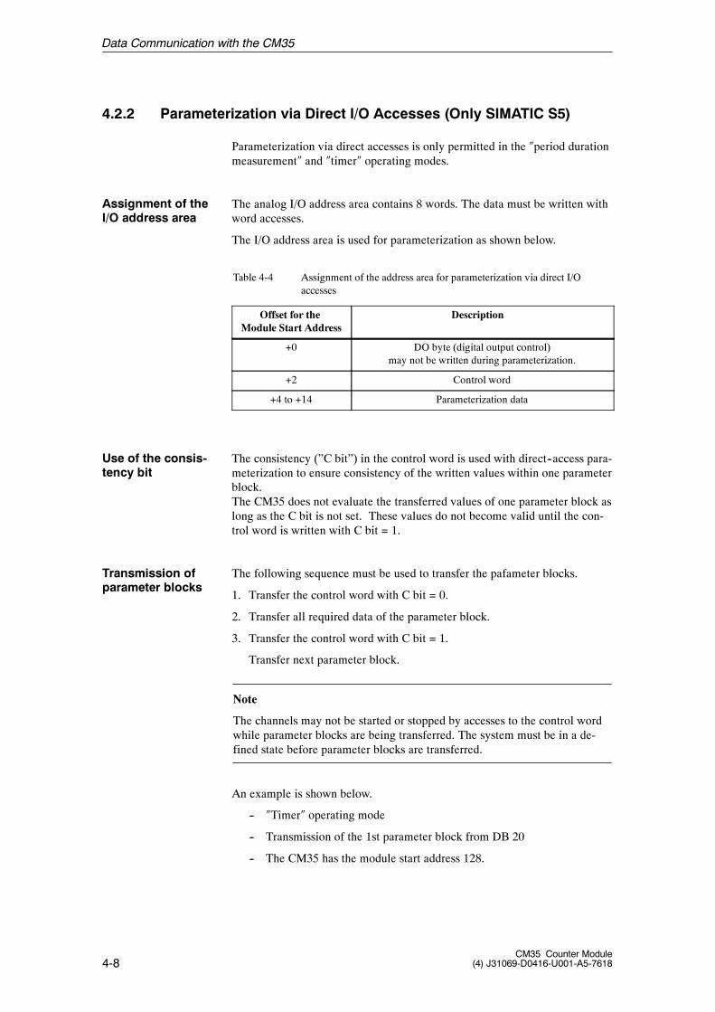
Parameterization via direct accesses is only permitted in the �period durationmeasurement� and �timer� operating modes.
The analog I/O address area contains 8 words. The data must be written withword accesses.
The I/O address area is used for parameterization as shown below.
Table 4-4 Assignment of the address area for parameterization via direct I/Oaccesses
Offset for theModule Start Address
Description
+0 DO byte (digital output control)may not be written during parameterization.
+2 Control word
+4 to +14 Parameterization data
The consistency (”C bit”) in the control word is used with direct--access para-meterization to ensure consistency of the written values within one parameterblock.The CM35 does not evaluate the transferred values of one parameter block aslong as the C bit is not set. These values do not become valid until the con-trol word is written with C bit = 1.
The following sequence must be used to transfer the pafameter blocks.
1. Transfer the control word with C bit = 0.
2. Transfer all required data of the parameter block.
3. Transfer the control word with C bit = 1.
Transfer next parameter block.
Note
The channels may not be started or stopped by accesses to the control wordwhile parameter blocks are being transferred. The system must be in a de-fined state before parameter blocks are transferred.
An example is shown below.
-- �Timer� operating mode
-- Transmission of the 1st parameter block from DB 20
-- The CM35 has the module start address 128.
Assignment of theI/O address area
Use of the consis-tency bit
Transmission ofparameter blocks
Data Communication with the CM35
4-9CM35 Counter Module(4) J31069-D0416-U001-A5-7618
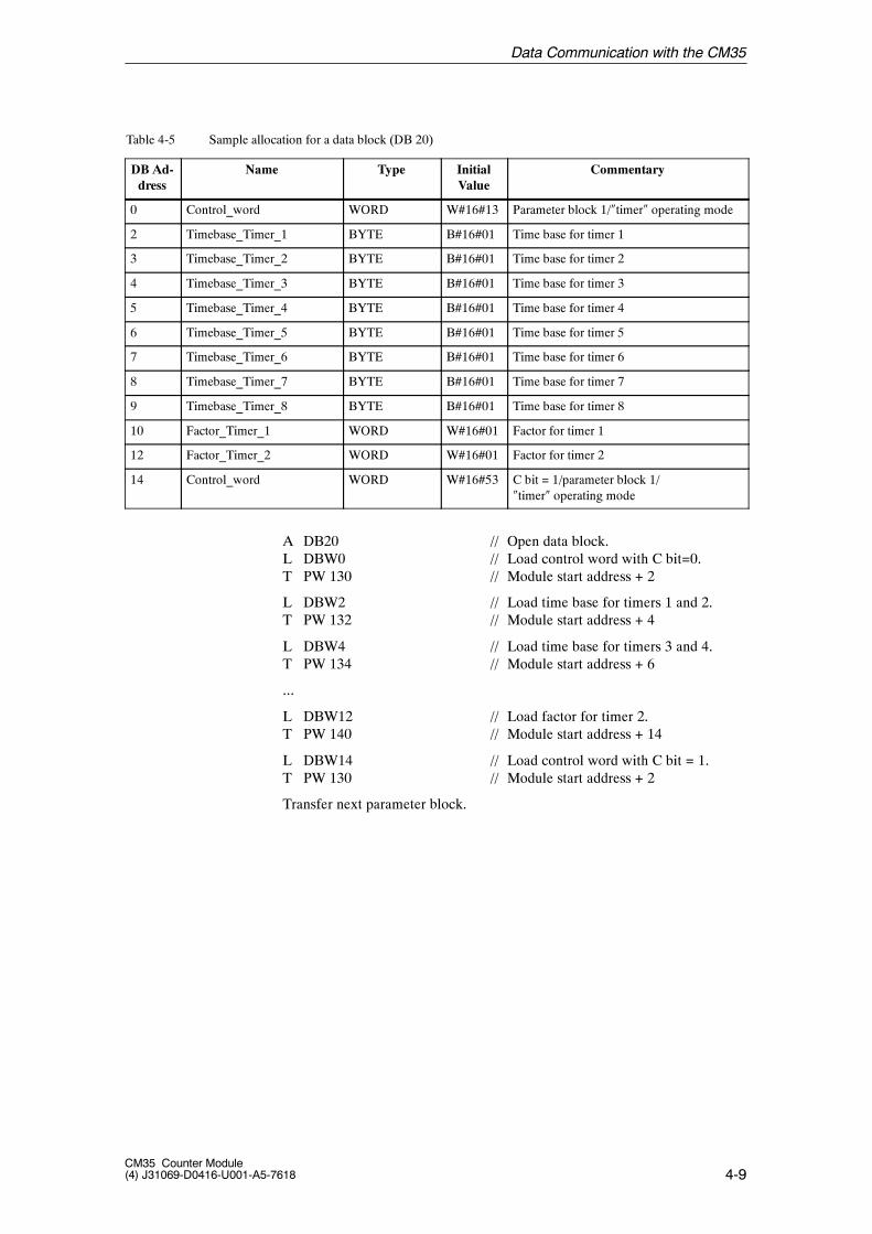
Table 4-5 Sample allocation for a data block (DB 20)
DB Ad-dress
Name Type InitialValue
Commentary
0 Control_word WORD W#16#13 Parameter block 1/�timer� operating mode
2 Timebase_Timer_1 BYTE B#16#01 Time base for timer 1
3 Timebase_Timer_2 BYTE B#16#01 Time base for timer 2
4 Timebase_Timer_3 BYTE B#16#01 Time base for timer 3
5 Timebase_Timer_4 BYTE B#16#01 Time base for timer 4
6 Timebase_Timer_5 BYTE B#16#01 Time base for timer 5
7 Timebase_Timer_6 BYTE B#16#01 Time base for timer 6
8 Timebase_Timer_7 BYTE B#16#01 Time base for timer 7
9 Timebase_Timer_8 BYTE B#16#01 Time base for timer 8
10 Factor_Timer_1 WORD W#16#01 Factor for timer 1
12 Factor_Timer_2 WORD W#16#01 Factor for timer 2
14 Control_word WORD W#16#53 C bit = 1/parameter block 1/�timer� operating mode
A DB20 // Open data block.L DBW0 // Load control word with C bit=0.T PW 130 // Module start address + 2
L DBW2 // Load time base for timers 1 and 2.T PW 132 // Module start address + 4
L DBW4 // Load time base for timers 3 and 4.T PW 134 // Module start address + 6
...
L DBW12 // Load factor for timer 2.T PW 140 // Module start address + 14
L DBW14 // Load control word with C bit = 1.T PW 130 // Module start address + 2
Transfer next parameter block.
Data Communication with the CM35
4-10CM35 Counter Module
(4) J31069-D0416-U001-A5-7618
When distributed connection to the SIMATIC S5 is used, a wait time must beadhered to after an S5 CPU STOP/RUN transition, before the module is para-meterized via direct I/O accesses.
The wait time depends on the PROFIBUS transmission speed set. It can beconfigured in OB 100 or OB 1.
The following standard values apply.
187.5 kbit/sec � 500 msec wait time: :1.5 kbit/sec � 100 ms wait time: :12 kbit/sec � 10 ms wait time
Wait time, OB1/OB100
Data Communication with the CM35
4-11CM35 Counter Module(4) J31069-D0416-U001-A5-7618
4.3 Programming
Parameterization must be correct before the channels and digital outputs canbe controlled and the actual values can be read.With both the SIMATIC S7 and the SIMATIC S5, direct I/O accesses are al-ways used. Only word or double--word accesses to even addresses can beused for I/O accesses.
4.3.1 Controlling the Channels
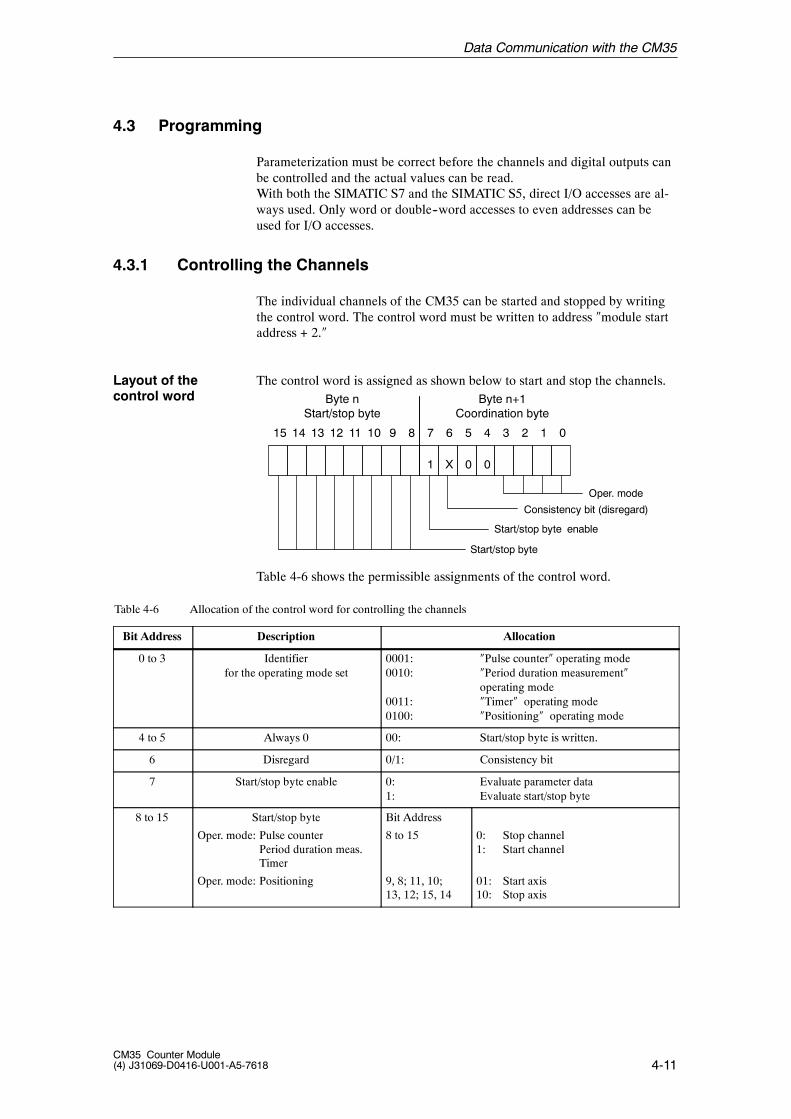
The individual channels of the CM35 can be started and stopped by writingthe control word. The control word must be written to address �module startaddress + 2.�
The control word is assigned as shown below to start and stop the channels.
15 14 13 12 11 10 9 8 7
1
6
X
5
0
4
0
3 2 1 0
Byte nStart/stop byte
Byte n+1Coordination byte
Oper. mode
Start/stop byte enable
Consistency bit (disregard)
Start/stop byte
Table 4-6 shows the permissible assignments of the control word.
Table 4-6 Allocation of the control word for controlling the channels
Bit Address Description Allocation
0 to 3 Identifierfor the operating mode set
0001: �Pulse counter� operating mode0010: �Period duration measurement�
operating mode0011: �Timer� operating mode0100: �Positioning� operating mode
4 to 5 Always 0 00: Start/stop byte is written.
6 Disregard 0/1: Consistency bit
7 Start/stop byte enable 0: Evaluate parameter data1: Evaluate start/stop byte
8 to 15 Start/stop byte
Oper. mode: Pulse counterPeriod duration meas.Timer
Oper. mode: Positioning
Bit Address
8 to 15
9, 8; 11, 10;13, 12; 15, 14
0: Stop channel1: Start channel
01: Start axis10: Stop axis
Layout of thecontrol word
Data Communication with the CM35

4-12CM35 Counter Module
(4) J31069-D0416-U001-A5-7618
Example: �Pulse counter� operating modeTo start all channels, write control word W#16#FF81.To stop all channels, write control word W#16#0081.
Data Communication with the CM35
4-13CM35 Counter Module(4) J31069-D0416-U001-A5-7618
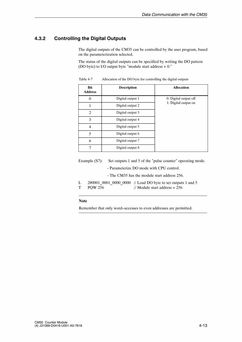
4.3.2 Controlling the Digital Outputs
The digital outputs of the CM35 can be controlled by the user program, basedon the parameterization selected.
The status of the digital outputs can be specified by writing the DO pattern(DO byte) to I/O output byte �module start address + 0.�
Table 4-7 Allocation of the DO byte for controlling the digital outputs
BitAddress
Description Allocation
0 Digital output 1 0: Digital output off1 Di it l t t
1 Digital output 21: Digital output on
2 Digital output 3
3 Digital output 4
4 Digital output 5
5 Digital output 6
6 Digital output 7
7 Digital output 8
Example (S7): Set outputs 1 and 5 of the �pulse counter� operating mode.
- Parameterize DO mode with CPU control.
- The CM35 has the module start address 256.
L 2#0001_0001_0000_0000 // Load DO byte to set outputs 1 and 5T PQW 256 // Module start address = 256
Note
Remember that only word--accesses to even addresses are permitted.
Data Communication with the CM35
4-14CM35 Counter Module
(4) J31069-D0416-U001-A5-7618
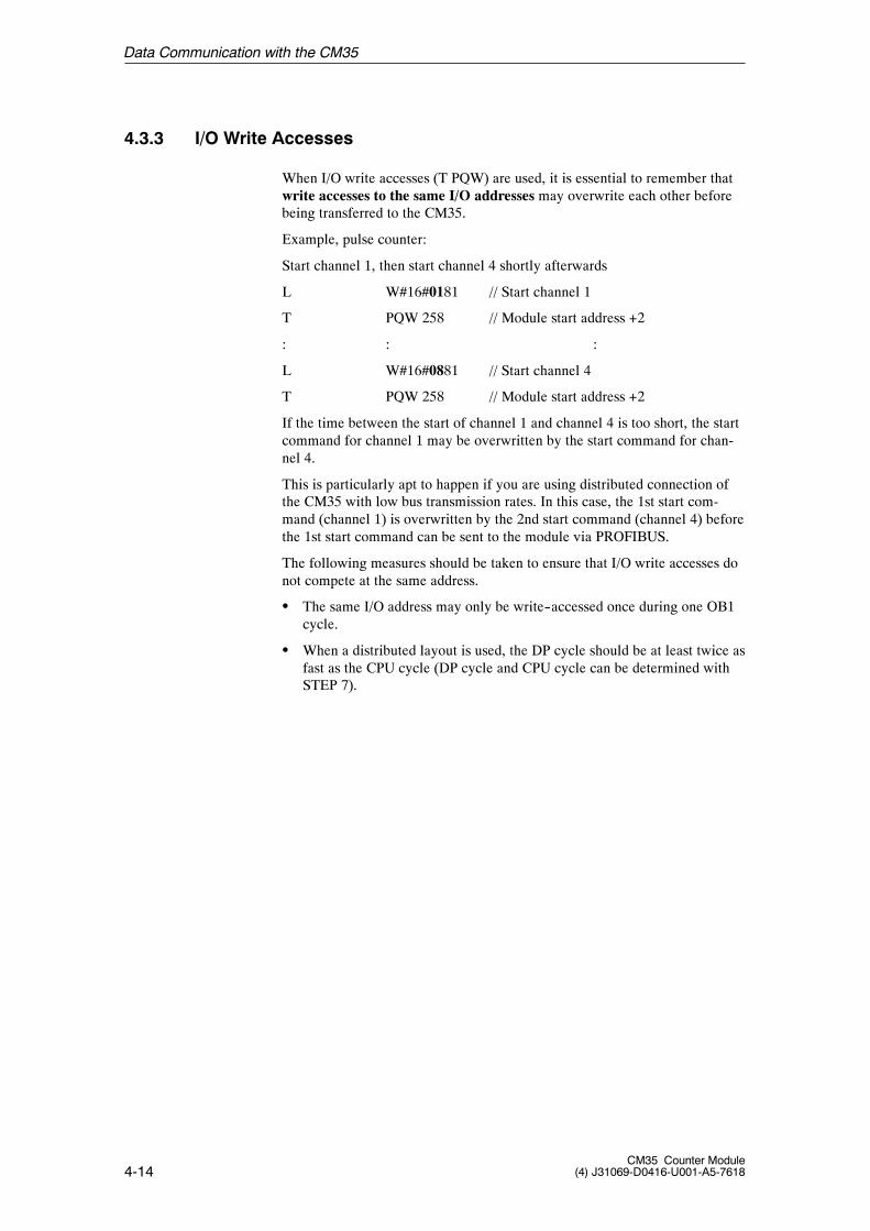
4.3.3 I/O Write Accesses
When I/O write accesses (T PQW) are used, it is essential to remember thatwrite accesses to the same I/O addresses may overwrite each other beforebeing transferred to the CM35.
Example, pulse counter:
Start channel 1, then start channel 4 shortly afterwards
L W#16#0181 // Start channel 1
T PQW 258 // Module start address +2
: : :
L W#16#0881 // Start channel 4
T PQW 258 // Module start address +2
If the time between the start of channel 1 and channel 4 is too short, the startcommand for channel 1 may be overwritten by the start command for chan-nel 4.
This is particularly apt to happen if you are using distributed connection ofthe CM35 with low bus transmission rates. In this case, the 1st start com-mand (channel 1) is overwritten by the 2nd start command (channel 4) beforethe 1st start command can be sent to the module via PROFIBUS.
The following measures should be taken to ensure that I/O write accesses donot compete at the same address.
S The same I/O address may only be write--accessed once during one OB1cycle.
S When a distributed layout is used, the DP cycle should be at least twice asfast as the CPU cycle (DP cycle and CPU cycle can be determined withSTEP 7).
Data Communication with the CM35
4-15CM35 Counter Module(4) J31069-D0416-U001-A5-7618
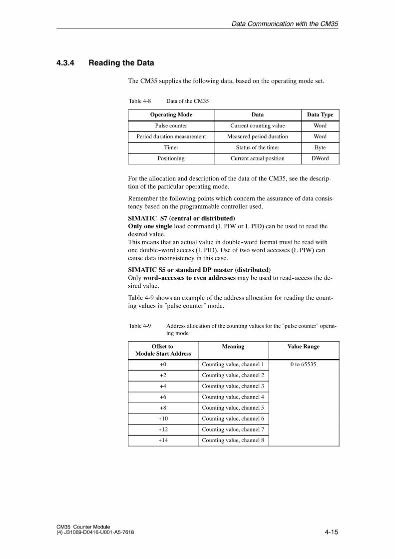
4.3.4 Reading the Data
The CM35 supplies the following data, based on the operating mode set.
Table 4-8 Data of the CM35
Operating Mode Data Data Type
Pulse counter Current counting value Word
Period duration measurement Measured period duration Word
Timer Status of the timer Byte
Positioning Current actual position DWord
For the allocation and description of the data of the CM35, see the descrip-tion of the particular operating mode.
Remember the following points which concern the assurance of data consis-tency based on the programmable controller used.
SIMATIC S7 (central or distributed)Only one single load command (L PIW or L PID) can be used to read thedesired value.This means that an actual value in double--word format must be read withone double--word access (L PID). Use of two word accesses (L PIW) cancause data inconsistency in this case.
SIMATIC S5 or standard DP master (distributed)Only word--accesses to even addresses may be used to read--access the de-sired value.
Table 4-9 shows an example of the address allocation for reading the count-ing values in �pulse counter� mode.
Table 4-9 Address allocation of the counting values for the �pulse counter� operat-ing mode
Offset toModule Start Address
Meaning Value Range
+0 Counting value, channel 1 0 to 65535
+2 Counting value, channel 2
+4 Counting value, channel 3
+6 Counting value, channel 4
+8 Counting value, channel 5
+10 Counting value, channel 6
+12 Counting value, channel 7
+14 Counting value, channel 8
Data Communication with the CM35
4-16CM35 Counter Module
(4) J31069-D0416-U001-A5-7618
Example: �Pulse counter� mode-- Read counting value of counting channel 4-- The CM35 has module start address 256.
L PIW 262 // Address = 256 + 6, read counting value,channel 4
T MW 8 // Save the counting value
Data Communication with the CM35
4-17CM35 Counter Module(4) J31069-D0416-U001-A5-7618
4.3.5 Evaluating a Hardware Interrupt in OB 40
Depending on the set operating mode and the selected parameterization, youcan specify that a hardware interrupt is to be triggered when certain eventsoccur. In this case, a hardware interrupt OB (OB 40) must exist on the CPU.
When a hardware interrupt occurs, the user program is interrupted, the dataof the module are transferred to the start information of OB 40, and OB 40 iscalled. The hardware interrupt is acknowledged when OB 40 is exited.
The following local data are located in the start information of OB 40.
-- OB 40_MDL_ADDR: The base address of the module which trig-gered the interrupt
-- OB 40_POINT_ADDR: Information on the event which triggered theinterrupt
Variable OB40_POINT_ADDR consists of four bytes. The processinterrupt information of the CM35 is entered in the low word (local databytes 10 and 11 of OB 40). For the allocation and description of this interruptinformation, see the description of the particular operating mode.
For a description of OB 40, see STEP 7 reference manual /235/.
Data Communication with the CM35
4-18CM35 Counter Module
(4) J31069-D0416-U001-A5-7618
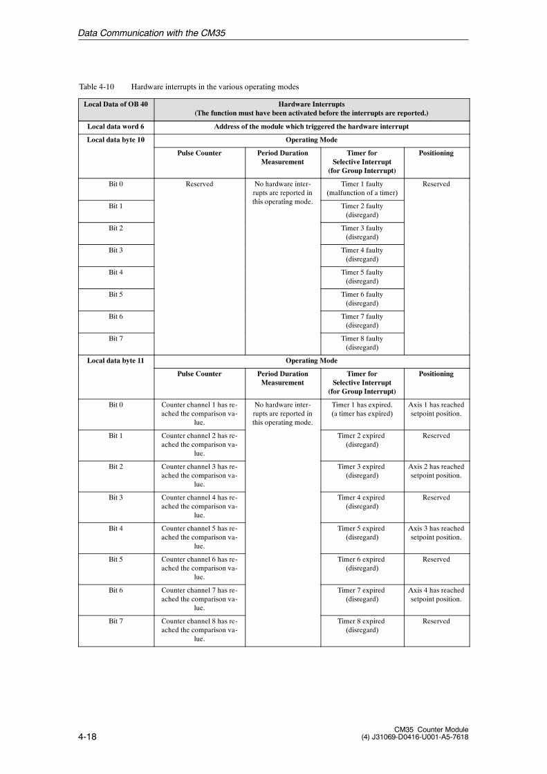
Table 4-10 Hardware interrupts in the various operating modes
Local Data of OB 40 Hardware Interrupts(The function must have been activated before the interrupts are reported.)
Local data word 6 Address of the module which triggered the hardware interrupt
Local data byte 10 Operating Mode
Pulse Counter Period DurationMeasurement
Timer forSelective Interrupt
(for Group Interrupt)
Positioning
Bit 0 Reserved No hardware inter-rupts are reported inthi ti d
Timer 1 faulty(malfunction of a timer)
Reserved
Bit 1this operating mode.
Timer 2 faulty(disregard)
Bit 2 Timer 3 faulty(disregard)
Bit 3 Timer 4 faulty(disregard)
Bit 4 Timer 5 faulty(disregard)
Bit 5 Timer 6 faulty(disregard)
Bit 6 Timer 7 faulty(disregard)
Bit 7 Timer 8 faulty(disregard)
Local data byte 11 Operating Mode
Pulse Counter Period DurationMeasurement
Timer forSelective Interrupt
(for Group Interrupt)
Positioning
Bit 0 Counter channel 1 has re-ached the comparison va-
lue.
No hardware inter-rupts are reported inthis operating mode.
Timer 1 has expired.(a timer has expired)
Axis 1 has reachedsetpoint position.
Bit 1 Counter channel 2 has re-ached the comparison va-
lue.
Timer 2 expired(disregard)
Reserved
Bit 2 Counter channel 3 has re-ached the comparison va-
lue.
Timer 3 expired(disregard)
Axis 2 has reachedsetpoint position.
Bit 3 Counter channel 4 has re-ached the comparison va-
lue.
Timer 4 expired(disregard)
Reserved
Bit 4 Counter channel 5 has re-ached the comparison va-
lue.
Timer 5 expired(disregard)
Axis 3 has reachedsetpoint position.
Bit 5 Counter channel 6 has re-ached the comparison va-
lue.
Timer 6 expired(disregard)
Reserved
Bit 6 Counter channel 7 has re-ached the comparison va-
lue.
Timer 7 expired(disregard)
Axis 4 has reachedsetpoint position.
Bit 7 Counter channel 8 has re-ached the comparison va-
lue.
Timer 8 expired(disregard)
Reserved
Data Communication with the CM35
4-19CM35 Counter Module(4) J31069-D0416-U001-A5-7618
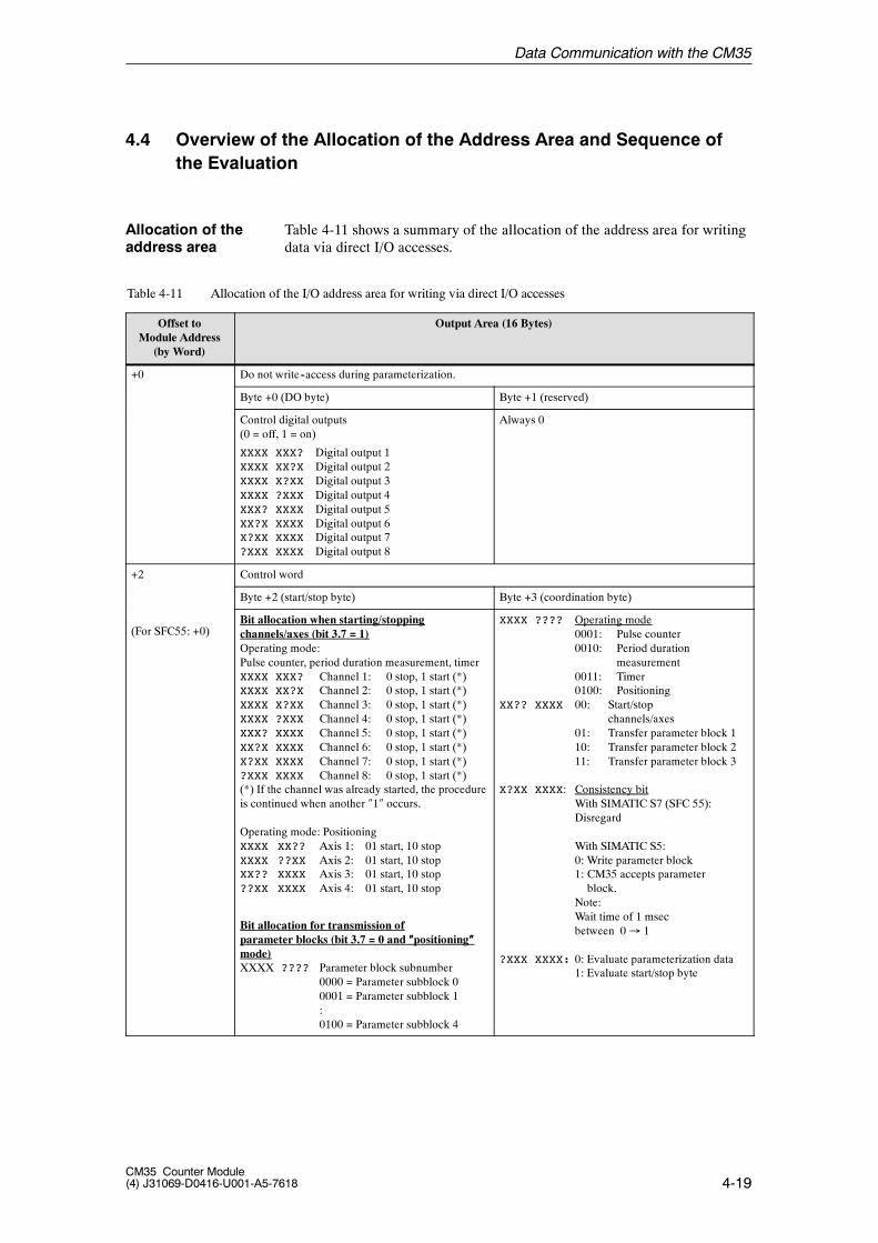
4.4 Overview of the Allocation of the Address Area and Sequence ofthe Evaluation
Table 4-11 shows a summary of the allocation of the address area for writingdata via direct I/O accesses.
Table 4-11 Allocation of the I/O address area for writing via direct I/O accesses
Offset toModule Address
(by Word)
Output Area (16 Bytes)
+0 Do not write--access during parameterization.
Byte +0 (DO byte) Byte +1 (reserved)
Control digital outputs(0 = off, 1 = on)
XXXX XXX? Digital output 1XXXX XX?X Digital output 2XXXX X?XX Digital output 3XXXX ?XXX Digital output 4XXX? XXXX Digital output 5XX?X XXXX Digital output 6X?XX XXXX Digital output 7?XXX XXXX Digital output 8
Always 0
+2 Control word
Byte +2 (start/stop byte) Byte +3 (coordination byte)
(For SFC55: +0)Bit allocation when starting/stoppingchannels/axes (bit 3.7 = 1)Operating mode:Pulse counter, period duration measurement, timerXXXX XXX? Channel 1: 0 stop, 1 start (*)XXXX XX?X Channel 2: 0 stop, 1 start (*)XXXX X?XX Channel 3: 0 stop, 1 start (*)XXXX ?XXX Channel 4: 0 stop, 1 start (*)XXX? XXXX Channel 5: 0 stop, 1 start (*)XX?X XXXX Channel 6: 0 stop, 1 start (*)X?XX XXXX Channel 7: 0 stop, 1 start (*)?XXX XXXX Channel 8: 0 stop, 1 start (*)(*) If the channel was already started, the procedureis continued when another �1� occurs.
Operating mode: PositioningXXXX XX?? Axis 1: 01 start, 10 stopXXXX ??XX Axis 2: 01 start, 10 stopXX?? XXXX Axis 3: 01 start, 10 stop??XX XXXX Axis 4: 01 start, 10 stop
Bit allocation for transmission ofparameter blocks (bit 3.7 = 0 and ����positioning����mode)XXXX ???? Parameter block subnumber
0000 = Parameter subblock 00001 = Parameter subblock 1:0100 = Parameter subblock 4
XXXX ???? Operating mode0001: Pulse counter0010: Period duration
measurement0011: Timer0100: Positioning
XX?? XXXX 00: Start/stopchannels/axes
01: Transfer parameter block 110: Transfer parameter block 211: Transfer parameter block 3
X?XX XXXX: Consistency bitWith SIMATIC S7 (SFC 55):Disregard
With SIMATIC S5:0: Write parameter block1: CM35 accepts parameterblock.
Note:Wait time of 1 msecbetween 0� 1
?XXX XXXX: 0: Evaluate parameterization data1: Evaluate start/stop byte
Allocation of theaddress area
Data Communication with the CM35
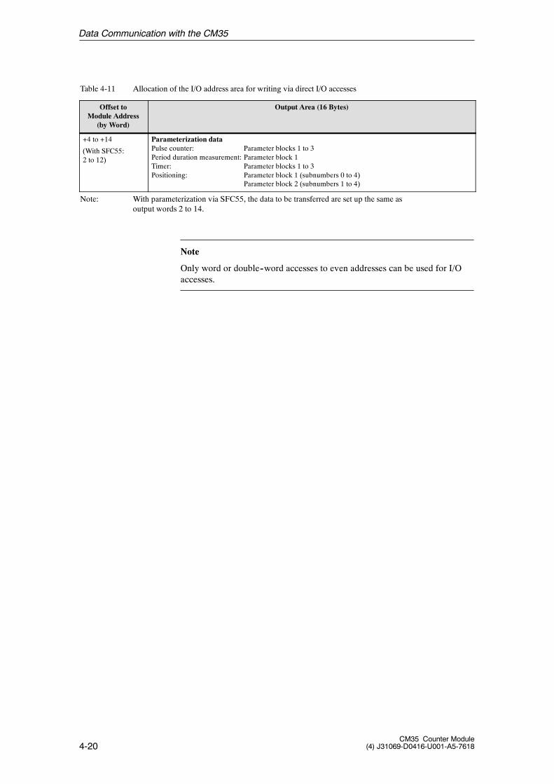
4-20CM35 Counter Module
(4) J31069-D0416-U001-A5-7618
Table 4-11 Allocation of the I/O address area for writing via direct I/O accesses
Output Area (16 Bytes)Offset toModule Address
(by Word)
+4 to +14
(With SFC55:2 to 12)
Parameterization dataPulse counter: Parameter blocks 1 to 3Period duration measurement: Parameter block 1Timer: Parameter blocks 1 to 3Positioning: Parameter block 1 (subnumbers 0 to 4)
Parameter block 2 (subnumbers 1 to 4)
Note: With parameterization via SFC55, the data to be transferred are set up the same asoutput words 2 to 14.
Note
Only word or double--word accesses to even addresses can be used for I/Oaccesses.
Data Communication with the CM35
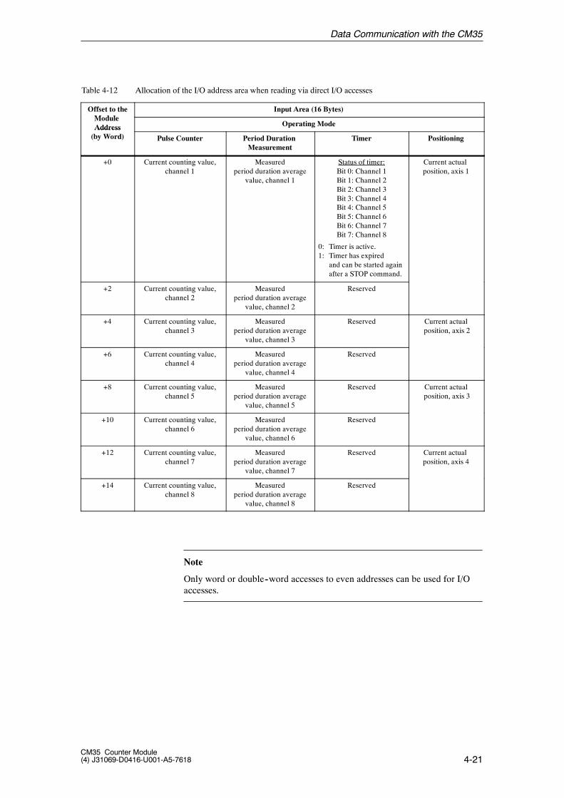
4-21CM35 Counter Module(4) J31069-D0416-U001-A5-7618
Table 4-12 Allocation of the I/O address area when reading via direct I/O accesses
Offset to theM d l
Input Area (16 Bytes)ModuleAddress Operating ModeAddress(by Word) Pulse Counter Period Duration
MeasurementTimer Positioning
+0 Current counting value,channel 1
Measuredperiod duration average
value, channel 1
Status of timer:Bit 0: Channel 1Bit 1: Channel 2Bit 2: Channel 3Bit 3: Channel 4Bit 4: Channel 5Bit 5: Channel 6Bit 6: Channel 7Bit 7: Channel 8
0: Timer is active.1: Timer has expired
and can be started againafter a STOP command.
Current actualposition, axis 1
+2 Current counting value,channel 2
Measuredperiod duration average
value, channel 2
Reserved
+4 Current counting value,channel 3
Measuredperiod duration average
value, channel 3
Reserved Current actualposition, axis 2
+6 Current counting value,channel 4
Measuredperiod duration average
value, channel 4
Reserved
+8 Current counting value,channel 5
Measuredperiod duration average
value, channel 5
Reserved Current actualposition, axis 3
+10 Current counting value,channel 6
Measuredperiod duration average
value, channel 6
Reserved
+12 Current counting value,channel 7
Measuredperiod duration average
value, channel 7
Reserved Current actualposition, axis 4
+14 Current counting value,channel 8
Measuredperiod duration average
value, channel 8
Reserved
Note
Only word or double--word accesses to even addresses can be used for I/Oaccesses.
Data Communication with the CM35
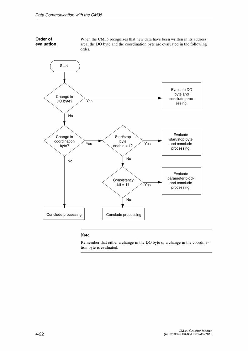
4-22CM35 Counter Module
(4) J31069-D0416-U001-A5-7618
When the CM35 recognizes that new data have been written in its addressarea, the DO byte and the coordination byte are evaluated in the followingorder.
Start
Change inDO byte?
Conclude processing
Change incoordination
byte?
Start/stopbyte
enable = 1?
Consistencybit = 1?
Conclude processing
Evaluate DObyte and
conclude proc-essing.
Evaluatestart/stop byteand concludeprocessing.
Evaluateparameter blockand concludeprocessing.
Yes
No
Yes
No
Yes
No
Yes
No
Note
Remember that either a change in the DO byte or a change in the coordina-tion byte is evaluated.
Order ofevaluation
Data Communication with the CM35

5-1CM35 Counter Module(4) J31069-D0416-U001-A5-7618
Pulse Counter Operating Mode 5
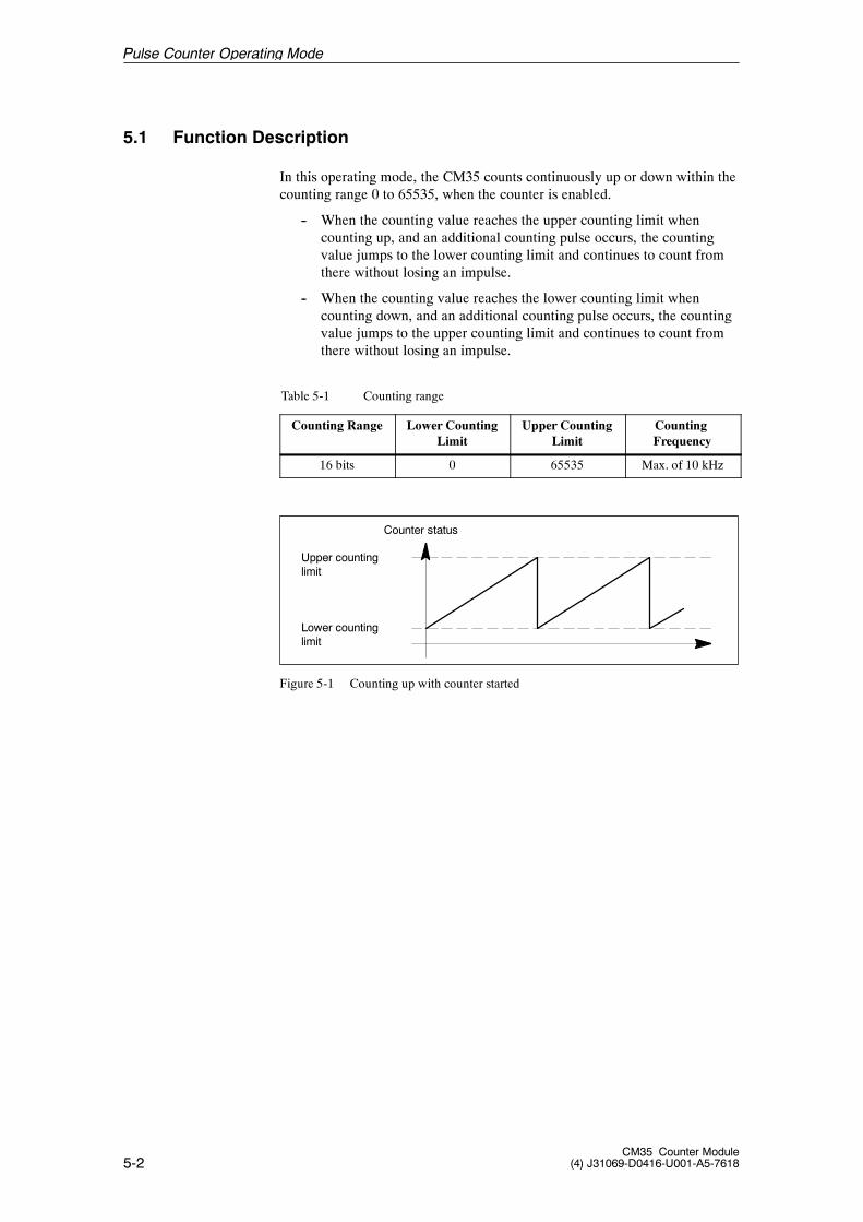
5-2CM35 Counter Module
(4) J31069-D0416-U001-A5-7618
5.1 Function Description
In this operating mode, the CM35 counts continuously up or down within thecounting range 0 to 65535, when the counter is enabled.
-- When the counting value reaches the upper counting limit whencounting up, and an additional counting pulse occurs, the countingvalue jumps to the lower counting limit and continues to count fromthere without losing an impulse.
-- When the counting value reaches the lower counting limit whencounting down, and an additional counting pulse occurs, the countingvalue jumps to the upper counting limit and continues to count fromthere without losing an impulse.
Table 5-1 Counting range
Counting Range Lower CountingLimit
Upper CountingLimit
CountingFrequency
16 bits 0 65535 Max. of 10 kHz
Upper countinglimit
Lower countinglimit
Counter status
Figure 5-1 Counting up with counter started
Pulse Counter Operating Mode
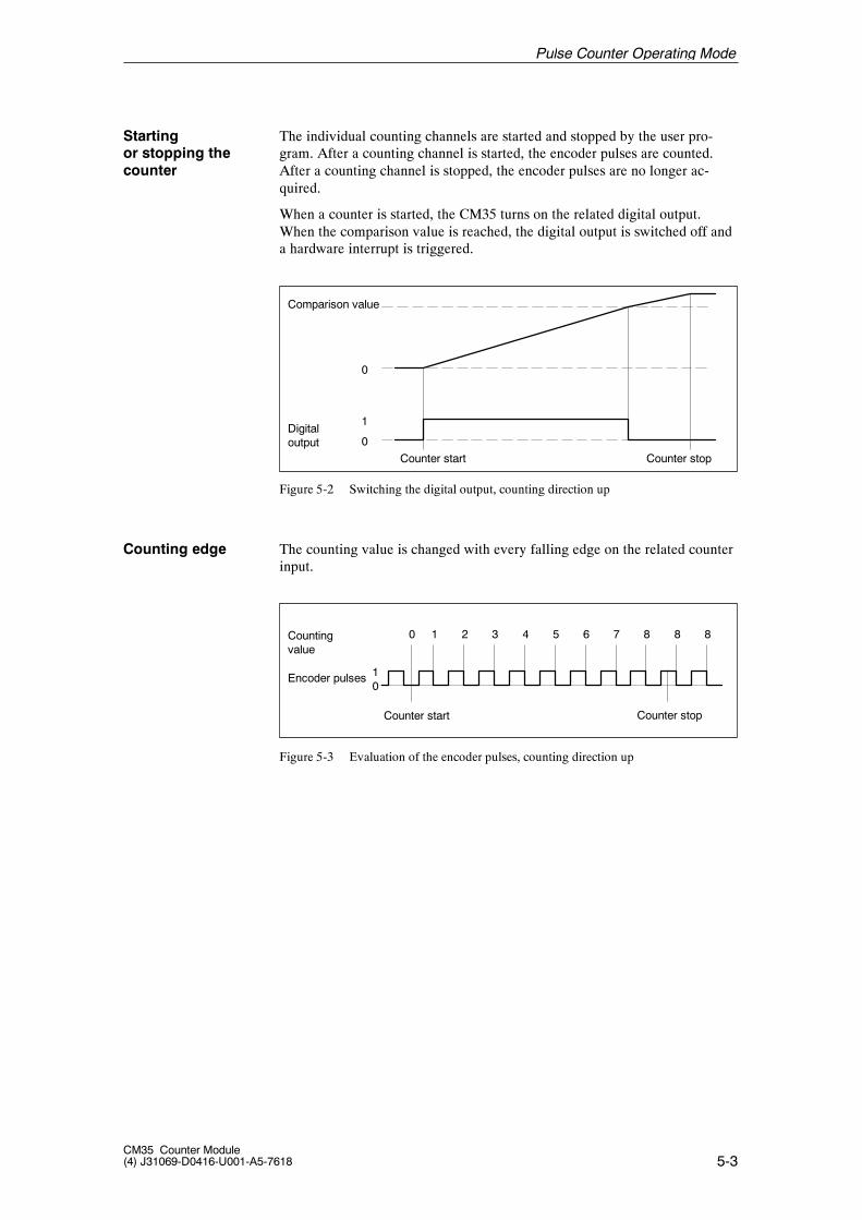
5-3CM35 Counter Module(4) J31069-D0416-U001-A5-7618
The individual counting channels are started and stopped by the user pro-gram. After a counting channel is started, the encoder pulses are counted.After a counting channel is stopped, the encoder pulses are no longer ac-quired.
When a counter is started, the CM35 turns on the related digital output.When the comparison value is reached, the digital output is switched off anda hardware interrupt is triggered.
Comparison value
Digitaloutput 0
Counter stopCounter start
1
0
Figure 5-2 Switching the digital output, counting direction up
The counting value is changed with every falling edge on the related counterinput.
Countingvalue
Encoder pulses
Counter stop
0 1 2 3 4 5 6 7 8 8 8
01
Counter start
Figure 5-3 Evaluation of the encoder pulses, counting direction up
Startingor stopping thecounter
Counting edge
Pulse Counter Operating Mode
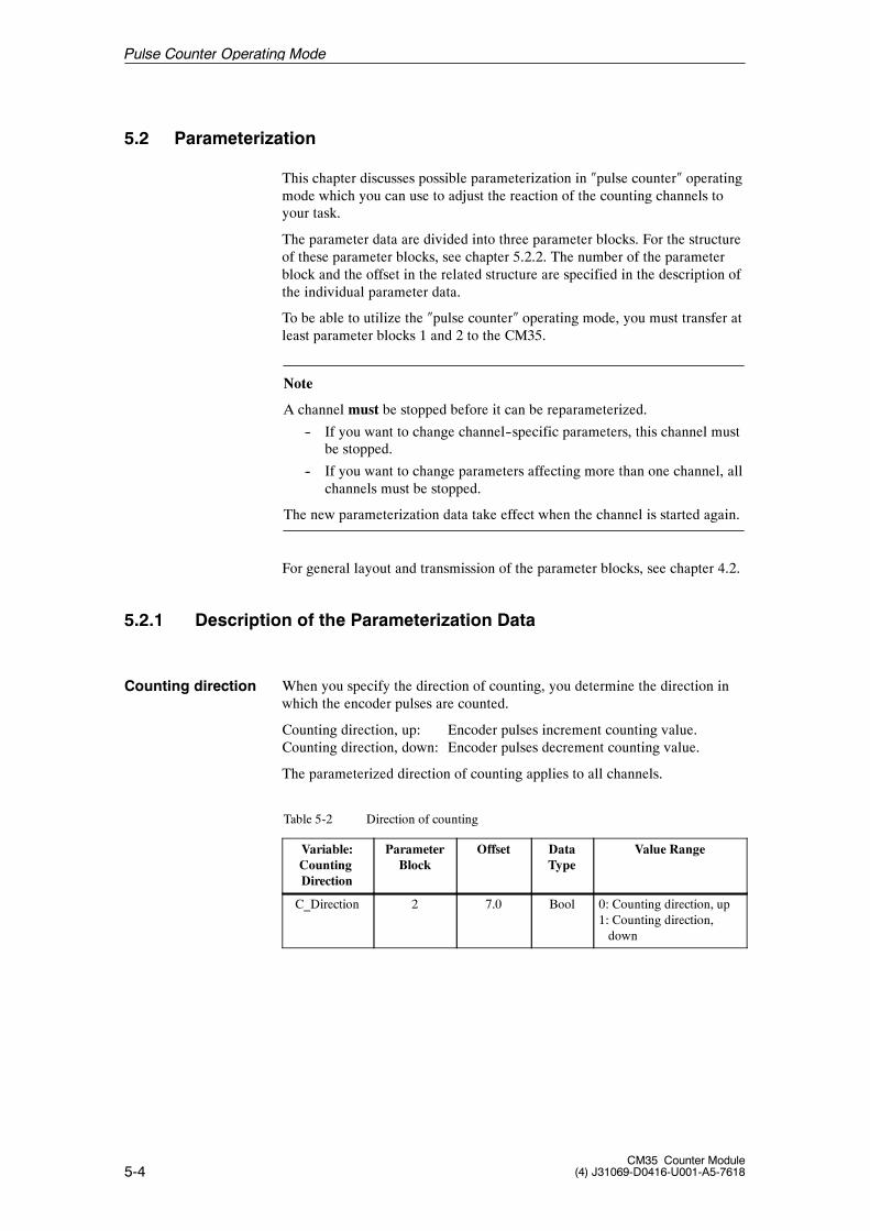
5-4CM35 Counter Module
(4) J31069-D0416-U001-A5-7618
5.2 Parameterization
This chapter discusses possible parameterization in �pulse counter� operatingmode which you can use to adjust the reaction of the counting channels toyour task.
The parameter data are divided into three parameter blocks. For the structureof these parameter blocks, see chapter 5.2.2. The number of the parameterblock and the offset in the related structure are specified in the description ofthe individual parameter data.
To be able to utilize the �pulse counter� operating mode, you must transfer atleast parameter blocks 1 and 2 to the CM35.
Note
A channel must be stopped before it can be reparameterized.
-- If you want to change channel--specific parameters, this channel mustbe stopped.
-- If you want to change parameters affecting more than one channel, allchannels must be stopped.
The new parameterization data take effect when the channel is started again.
For general layout and transmission of the parameter blocks, see chapter 4.2.
5.2.1 Description of the Parameterization Data
When you specify the direction of counting, you determine the direction inwhich the encoder pulses are counted.
Counting direction, up: Encoder pulses increment counting value.Counting direction, down: Encoder pulses decrement counting value.
The parameterized direction of counting applies to all channels.
Table 5-2 Direction of counting
Variable:CountingDirection
ParameterBlock
Offset DataType
Value Range
C_Direction 2 7.0 Bool 0: Counting direction, up1: Counting direction,down
Counting direction
Pulse Counter Operating Mode
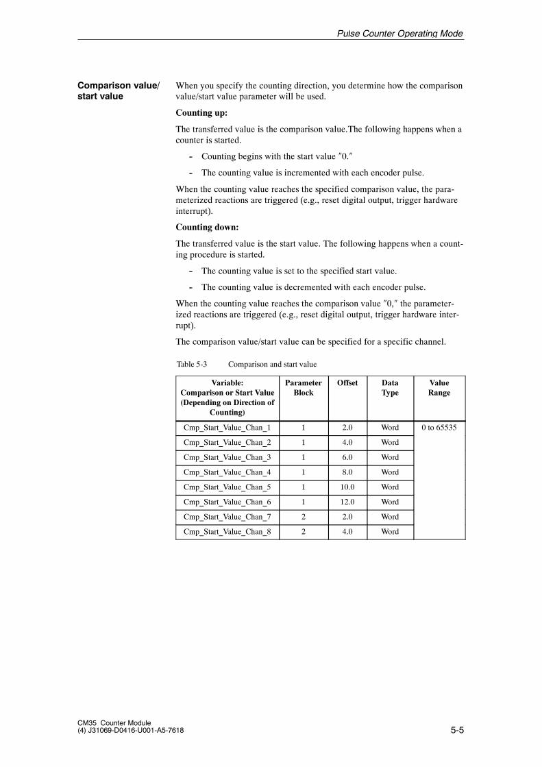
5-5CM35 Counter Module(4) J31069-D0416-U001-A5-7618
When you specify the counting direction, you determine how the comparisonvalue/start value parameter will be used.
Counting up:
The transferred value is the comparison value.The following happens when acounter is started.
-- Counting begins with the start value �0.�
-- The counting value is incremented with each encoder pulse.
When the counting value reaches the specified comparison value, the para-meterized reactions are triggered (e.g., reset digital output, trigger hardwareinterrupt).
Counting down:
The transferred value is the start value. The following happens when a count-ing procedure is started.
-- The counting value is set to the specified start value.
-- The counting value is decremented with each encoder pulse.
When the counting value reaches the comparison value �0,� the parameter-ized reactions are triggered (e.g., reset digital output, trigger hardware inter-rupt).
The comparison value/start value can be specified for a specific channel.
Table 5-3 Comparison and start value
Variable:Comparison or Start Value(Depending on Direction of
Counting)
ParameterBlock
Offset DataType
ValueRange
Cmp_Start_Value_Chan_1 1 2.0 Word 0 to 65535
Cmp_Start_Value_Chan_2 1 4.0 Word
Cmp_Start_Value_Chan_3 1 6.0 Word
Cmp_Start_Value_Chan_4 1 8.0 Word
Cmp_Start_Value_Chan_5 1 10.0 Word
Cmp_Start_Value_Chan_6 1 12.0 Word
Cmp_Start_Value_Chan_7 2 2.0 Word
Cmp_Start_Value_Chan_8 2 4.0 Word
Comparison value/start value
Pulse Counter Operating Mode
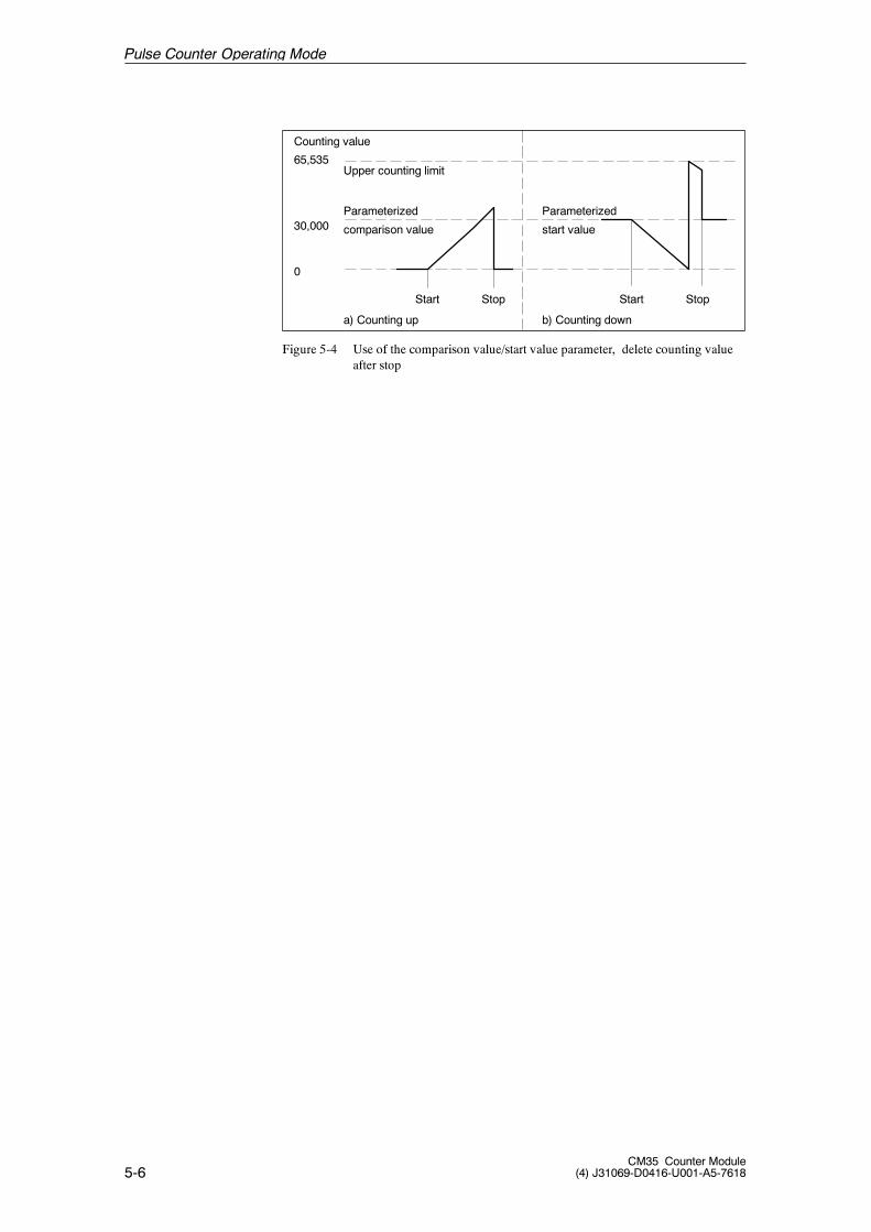
5-6CM35 Counter Module
(4) J31069-D0416-U001-A5-7618
65,535
30,000Parameterized
Counting value
Start
0
Stop Start Stop
Parameterized
a) Counting up b) Counting down
Upper counting limit
comparison value start value
Figure 5-4 Use of the comparison value/start value parameter, delete counting valueafter stop
Pulse Counter Operating Mode
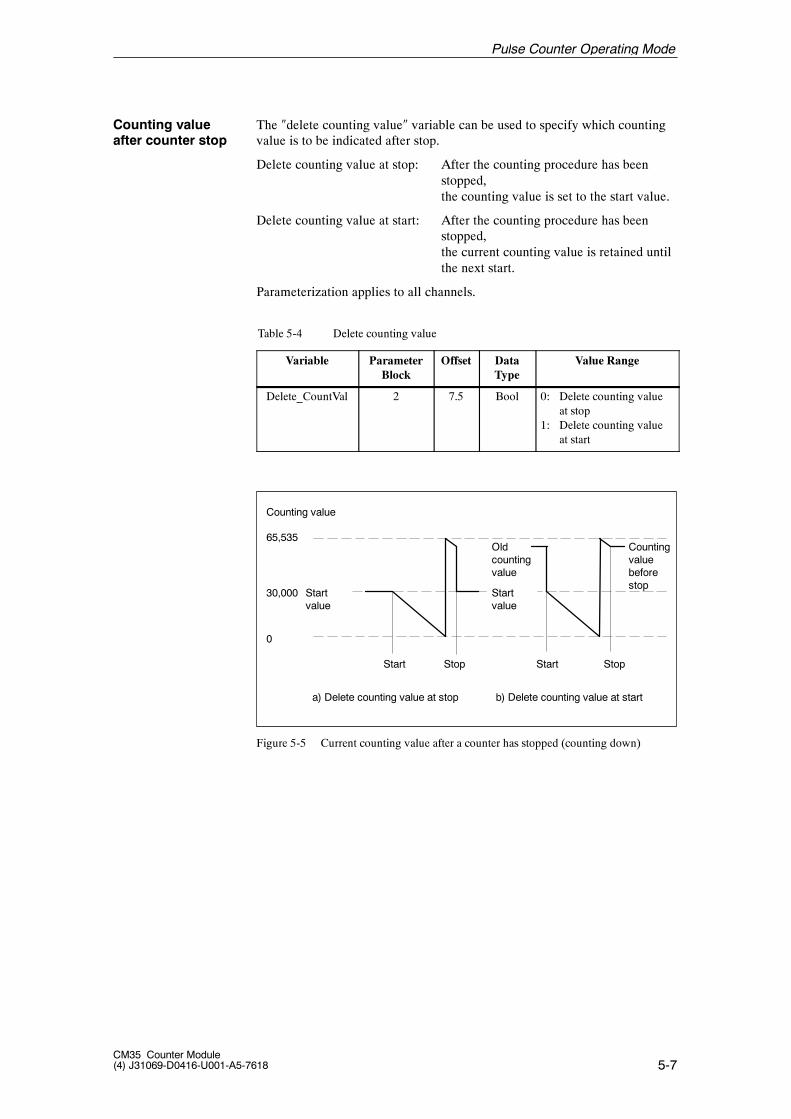
5-7CM35 Counter Module(4) J31069-D0416-U001-A5-7618
The �delete counting value� variable can be used to specify which countingvalue is to be indicated after stop.
Delete counting value at stop: After the counting procedure has beenstopped,the counting value is set to the start value.
Delete counting value at start: After the counting procedure has beenstopped,the current counting value is retained untilthe next start.
Parameterization applies to all channels.
Table 5-4 Delete counting value
Variable ParameterBlock
Offset DataType
Value Range
Delete_CountVal 2 7.5 Bool 0: Delete counting valueat stop
1: Delete counting valueat start
65,535
30,000 Startvalue
Counting value
Start
0
Stop Start Stop
Startvalue
Oldcountingvalue
a) Delete counting value at stop b) Delete counting value at start
Countingvaluebeforestop
Figure 5-5 Current counting value after a counter has stopped (counting down)
Counting valueafter counter stop
Pulse Counter Operating Mode
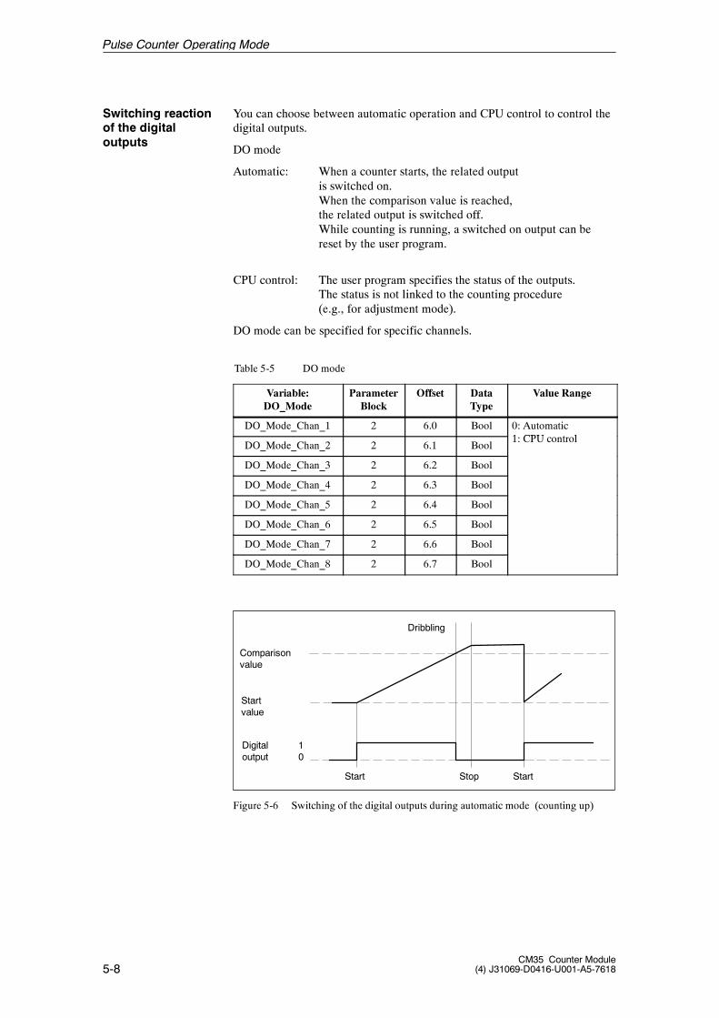
5-8CM35 Counter Module
(4) J31069-D0416-U001-A5-7618
You can choose between automatic operation and CPU control to control thedigital outputs.
DO mode
Automatic: When a counter starts, the related outputis switched on.When the comparison value is reached,the related output is switched off.While counting is running, a switched on output can bereset by the user program.
CPU control: The user program specifies the status of the outputs.The status is not linked to the counting procedure(e.g., for adjustment mode).
DO mode can be specified for specific channels.
Table 5-5 DO mode
Variable:DO_Mode
ParameterBlock
Offset DataType
Value Range
DO_Mode_Chan_1 2 6.0 Bool 0: Automatic1 CPU l
DO_Mode_Chan_2 2 6.1 Bool1: CPU control
DO_Mode_Chan_3 2 6.2 Bool
DO_Mode_Chan_4 2 6.3 Bool
DO_Mode_Chan_5 2 6.4 Bool
DO_Mode_Chan_6 2 6.5 Bool
DO_Mode_Chan_7 2 6.6 Bool
DO_Mode_Chan_8 2 6.7 Bool
Comparisonvalue
Startvalue
Digitaloutput
Stop
Dribbling
10
StartStart
Figure 5-6 Switching of the digital outputs during automatic mode (counting up)
Switching reactionof the digitaloutputs
Pulse Counter Operating Mode
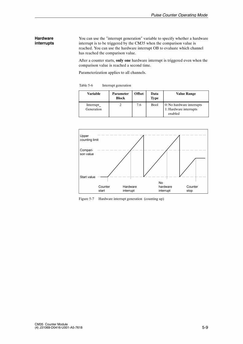
5-9CM35 Counter Module(4) J31069-D0416-U001-A5-7618
You can use the �interrupt generation� variable to specify whether a hardwareinterrupt is to be triggered by the CM35 when the comparison value isreached. You can use the hardware interrupt OB to evaluate which channelhas reached the comparison value.
After a counter starts, only one hardware interrupt is triggered even when thecomparison value is reached a second time.
Parameterization applies to all channels.
Table 5-6 Interrupt generation
Variable ParameterBlock
Offset DataType
Value Range
Interrupt_Generation
2 7.6 Bool 0:No hardware interrupts1:Hardware interruptsenabled
Uppercounting limit
Compari-son value
Counterstart
Start value
Hardwareinterrupt
Nohardwareinterrupt
Counterstop
Figure 5-7 Hardware interrupt generation (counting up)
Hardwareinterrupts
Pulse Counter Operating Mode
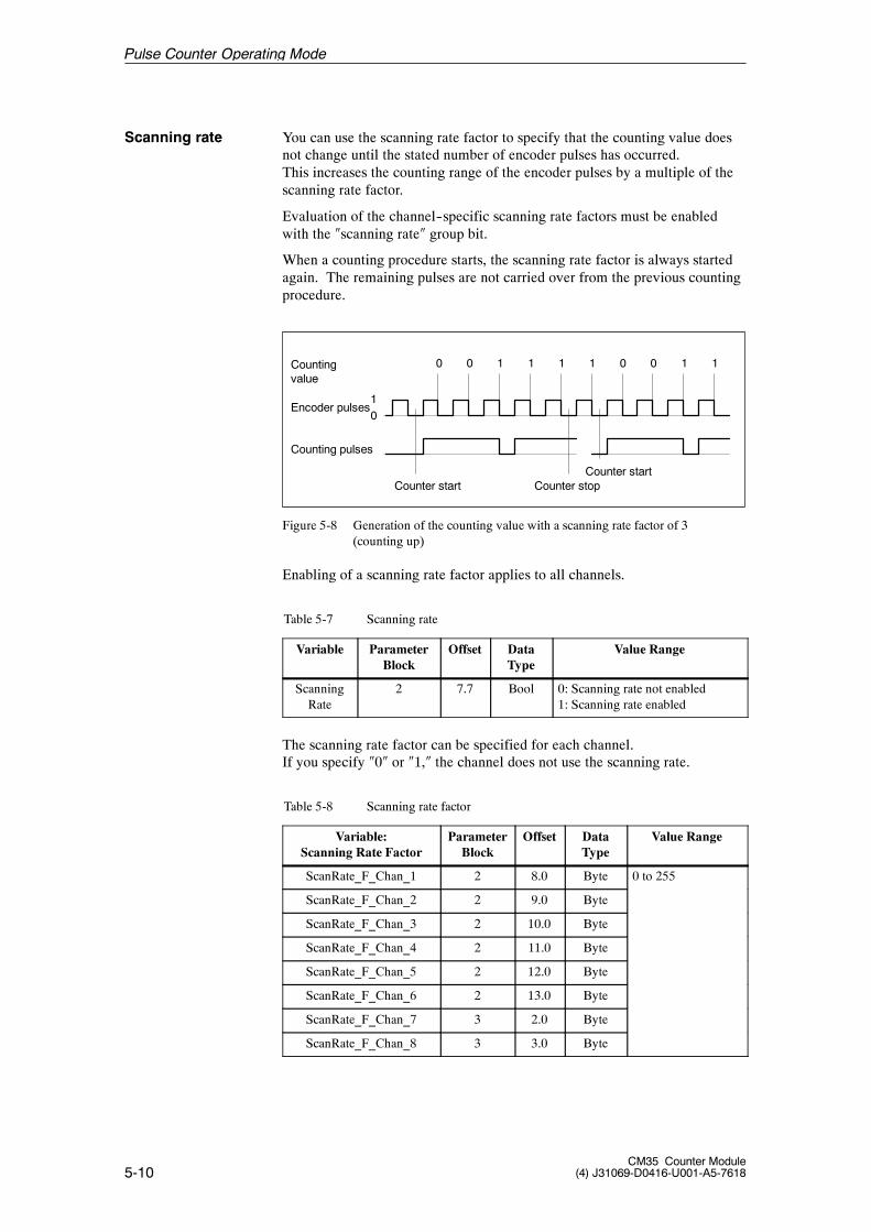
5-10CM35 Counter Module
(4) J31069-D0416-U001-A5-7618
You can use the scanning rate factor to specify that the counting value doesnot change until the stated number of encoder pulses has occurred.This increases the counting range of the encoder pulses by a multiple of thescanning rate factor.
Evaluation of the channel--specific scanning rate factors must be enabledwith the �scanning rate� group bit.
When a counting procedure starts, the scanning rate factor is always startedagain. The remaining pulses are not carried over from the previous countingprocedure.
Countingvalue
Encoder pulses
Counter start Counter stop
0 0 1 1 1 1 0 0 1 1
01
Counting pulses
Counter start
Figure 5-8 Generation of the counting value with a scanning rate factor of 3(counting up)
Enabling of a scanning rate factor applies to all channels.
Table 5-7 Scanning rate
Variable ParameterBlock
Offset DataType
Value Range
ScanningRate
2 7.7 Bool 0: Scanning rate not enabled1: Scanning rate enabled
The scanning rate factor can be specified for each channel.If you specify �0� or �1,� the channel does not use the scanning rate.
Table 5-8 Scanning rate factor
Variable:Scanning Rate Factor
ParameterBlock
Offset DataType
Value Range
ScanRate_F_Chan_1 2 8.0 Byte 0 to 255
ScanRate_F_Chan_2 2 9.0 Byte
ScanRate_F_Chan_3 2 10.0 Byte
ScanRate_F_Chan_4 2 11.0 Byte
ScanRate_F_Chan_5 2 12.0 Byte
ScanRate_F_Chan_6 2 13.0 Byte
ScanRate_F_Chan_7 3 2.0 Byte
ScanRate_F_Chan_8 3 3.0 Byte
Scanning rate
Pulse Counter Operating Mode
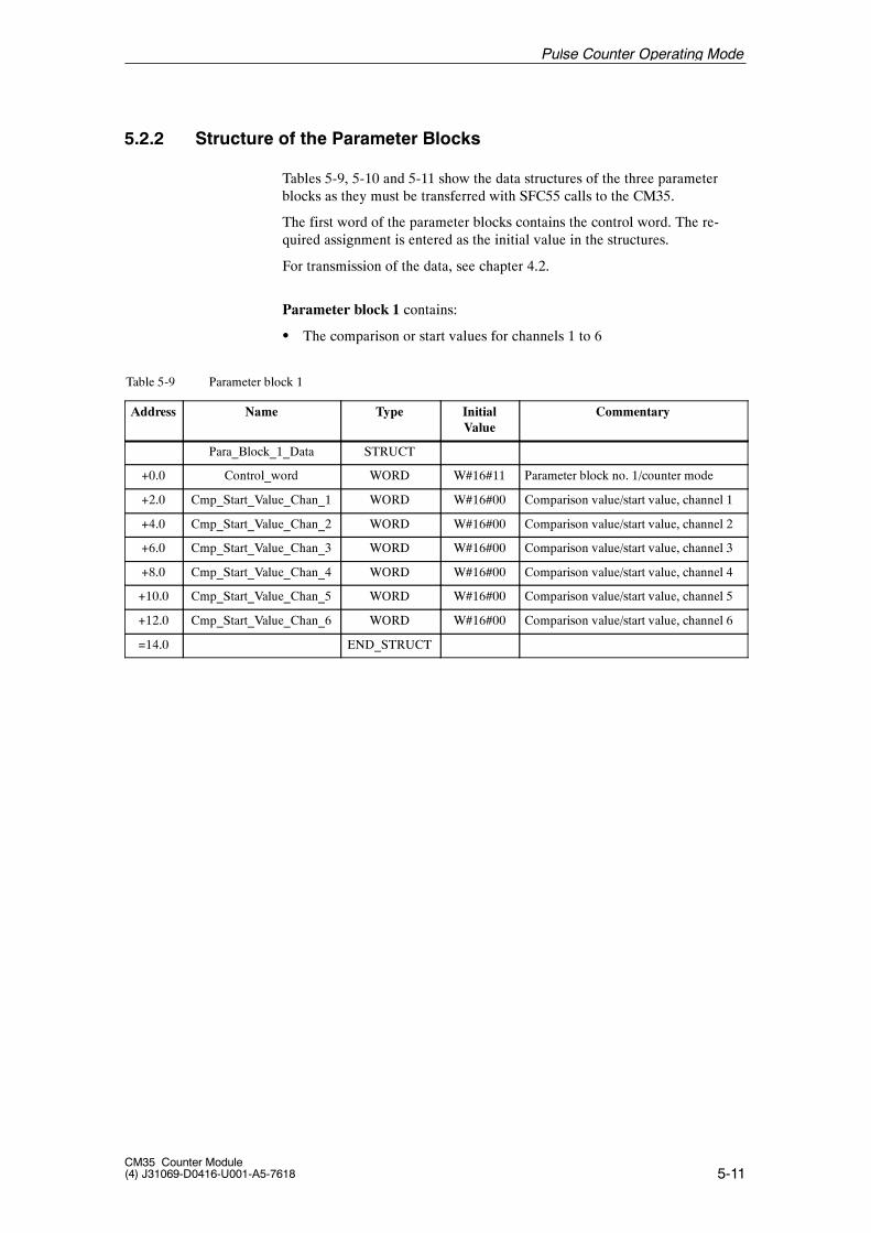
5-11CM35 Counter Module(4) J31069-D0416-U001-A5-7618
5.2.2 Structure of the Parameter Blocks
Tables 5-9, 5-10 and 5-11 show the data structures of the three parameterblocks as they must be transferred with SFC55 calls to the CM35.
The first word of the parameter blocks contains the control word. The re-quired assignment is entered as the initial value in the structures.
For transmission of the data, see chapter 4.2.
Parameter block 1 contains:
S The comparison or start values for channels 1 to 6
Table 5-9 Parameter block 1
Address Name Type InitialValue
Commentary
Para_Block_1_Data STRUCT
+0.0 Control_word WORD W#16#11 Parameter block no. 1/counter mode
+2.0 Cmp_Start_Value_Chan_1 WORD W#16#00 Comparison value/start value, channel 1
+4.0 Cmp_Start_Value_Chan_2 WORD W#16#00 Comparison value/start value, channel 2
+6.0 Cmp_Start_Value_Chan_3 WORD W#16#00 Comparison value/start value, channel 3
+8.0 Cmp_Start_Value_Chan_4 WORD W#16#00 Comparison value/start value, channel 4
+10.0 Cmp_Start_Value_Chan_5 WORD W#16#00 Comparison value/start value, channel 5
+12.0 Cmp_Start_Value_Chan_6 WORD W#16#00 Comparison value/start value, channel 6
=14.0 END_STRUCT
Pulse Counter Operating Mode
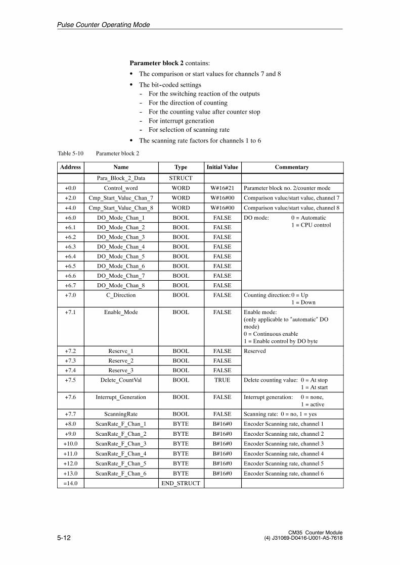
5-12CM35 Counter Module
(4) J31069-D0416-U001-A5-7618
Parameter block 2 contains:
S The comparison or start values for channels 7 and 8
S The bit--coded settings-- For the switching reaction of the outputs-- For the direction of counting-- For the counting value after counter stop-- For interrupt generation-- For selection of scanning rate
S The scanning rate factors for channels 1 to 6
Table 5-10 Parameter block 2
Address Name Type Initial Value Commentary
Para_Block_2_Data STRUCT
+0.0 Control_word WORD W#16#21 Parameter block no. 2/counter mode
+2.0 Cmp_Start_Value_Chan_7 WORD W#16#00 Comparison value/start value, channel 7
+4.0 Cmp_Start_Value_Chan_8 WORD W#16#00 Comparison value/start value, channel 8
+6.0 DO_Mode_Chan_1 BOOL FALSE DO mode: 0 = Automatic
+6.1 DO_Mode_Chan_2 BOOL FALSE 1 = CPU control
+6.2 DO_Mode_Chan_3 BOOL FALSE
+6.3 DO_Mode_Chan_4 BOOL FALSE
+6.4 DO_Mode_Chan_5 BOOL FALSE
+6.5 DO_Mode_Chan_6 BOOL FALSE
+6.6 DO_Mode_Chan_7 BOOL FALSE
+6.7 DO_Mode_Chan_8 BOOL FALSE
+7.0 C_Direction BOOL FALSE Counting direction:0 = Up1 = Down
+7.1 Enable_Mode BOOL FALSE Enable mode:(only applicable to �automatic� DOmode)0 = Continuous enable1 = Enable control by DO byte
+7.2 Reserve_1 BOOL FALSE Reserved
+7.3 Reserve_2 BOOL FALSE
+7.4 Reserve_3 BOOL FALSE
+7.5 Delete_CountVal BOOL TRUE Delete counting value: 0 = At stop1 = At start
+7.6 Interrupt_Generation BOOL FALSE Interrupt generation: 0 = none,1 = active
+7.7 ScanningRate BOOL FALSE Scanning rate: 0 = no, 1 = yes
+8.0 ScanRate_F_Chan_1 BYTE B#16#0 Encoder Scanning rate, channel 1
+9.0 ScanRate_F_Chan_2 BYTE B#16#0 Encoder Scanning rate, channel 2
+10.0 ScanRate_F_Chan_3 BYTE B#16#0 Encoder Scanning rate, channel 3
+11.0 ScanRate_F_Chan_4 BYTE B#16#0 Encoder Scanning rate, channel 4
+12.0 ScanRate_F_Chan_5 BYTE B#16#0 Encoder Scanning rate, channel 5
+13.0 ScanRate_F_Chan_6 BYTE B#16#0 Encoder Scanning rate, channel 6
=14.0 END_STRUCT
Pulse Counter Operating Mode
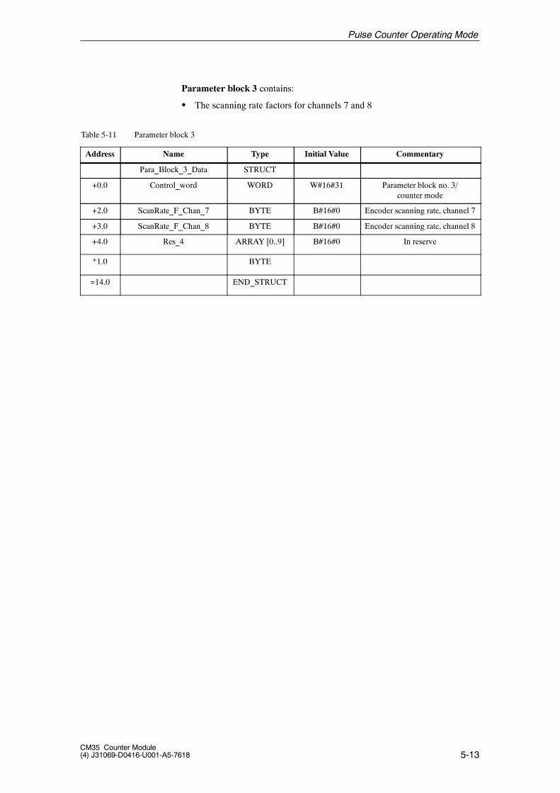
5-13CM35 Counter Module(4) J31069-D0416-U001-A5-7618
Parameter block 3 contains:
S The scanning rate factors for channels 7 and 8
Table 5-11 Parameter block 3
Address Name Type Initial Value Commentary
Para_Block_3_Data STRUCT
+0.0 Control_word WORD W#16#31 Parameter block no. 3/counter mode
+2.0 ScanRate_F_Chan_7 BYTE B#16#0 Encoder scanning rate, channel 7
+3.0 ScanRate_F_Chan_8 BYTE B#16#0 Encoder scanning rate, channel 8
+4.0 Res_4 ARRAY [0..9] B#16#0 In reserve
*1.0 BYTE
=14.0 END_STRUCT
Pulse Counter Operating Mode
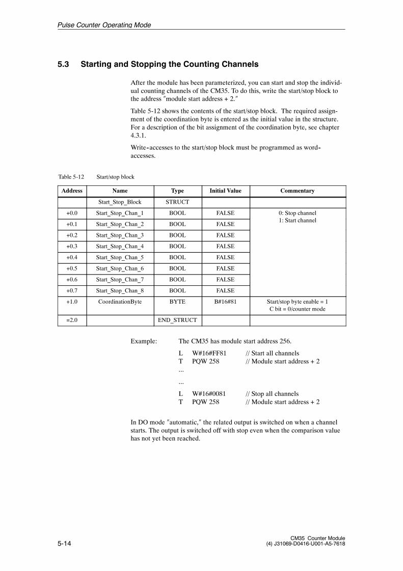
5-14CM35 Counter Module
(4) J31069-D0416-U001-A5-7618
5.3 Starting and Stopping the Counting Channels
After the module has been parameterized, you can start and stop the individ-ual counting channels of the CM35. To do this, write the start/stop block tothe address �module start address + 2.�
Table 5-12 shows the contents of the start/stop block. The required assign-ment of the coordination byte is entered as the initial value in the structure.For a description of the bit assignment of the coordination byte, see chapter4.3.1.
Write--accesses to the start/stop block must be programmed as word--accesses.
Table 5-12 Start/stop block
Address Name Type Initial Value Commentary
Start_Stop_Block STRUCT
+0.0 Start_Stop_Chan_1 BOOL FALSE 0: Stop channel1 S h l
+0.1 Start_Stop_Chan_2 BOOL FALSE1: Start channel
+0.2 Start_Stop_Chan_3 BOOL FALSE
+0.3 Start_Stop_Chan_4 BOOL FALSE
+0.4 Start_Stop_Chan_5 BOOL FALSE
+0.5 Start_Stop_Chan_6 BOOL FALSE
+0.6 Start_Stop_Chan_7 BOOL FALSE
+0.7 Start_Stop_Chan_8 BOOL FALSE
+1.0 CoordinationByte BYTE B#16#81 Start/stop byte enable = 1C bit = 0/counter mode
=2.0 END_STRUCT
Example: The CM35 has module start address 256.
L W#16#FF81 // Start all channelsT PQW 258 // Module start address + 2...
...
L W#16#0081 // Stop all channelsT PQW 258 // Module start address + 2
In DO mode �automatic,� the related output is switched on when a channelstarts. The output is switched off with stop even when the comparison valuehas not yet been reached.
Pulse Counter Operating Mode
5-15CM35 Counter Module(4) J31069-D0416-U001-A5-7618
5.4 Controlling the Digital Outputs
You can control the digital outputs of the CM35 as shown below, based onthe parameterization of DO mode.
DO mode:
Automatic: Note:A parameterization bit can be used to specify whetherthe DO byte is to control the enableor whether the enable is continuous.
Enable mode = ����Enable control via DO byte����The DO byte is used to enable the output forcontrol via the counter status.
0: Output disabled-- The output is not switched on with the start ofcounting.
-- A switched on output is forcibly switched off.
1: Output enabled-- The output is switched on at start of counting.-- The output is switched off when the comparisonvalue is reached or counting is stopped.
Enable mode = ����continuous enable����Control via the counter status is continuously enabled forthe outputs. A switched on output can be forcibly switchedoff with the DO byte.0: A switched on output is forcibly switched
off.(The forced switch--off only affects the currentcounting procedure.)
1: No effect
CPU control: You specify the state of the output with the DObyte.0: Switch off output1: Switch on output
Write the DO byte to the address �module start address + 0.�
Note
Control of the digital outputs must be programmed with a word access.
Pulse Counter Operating Mode
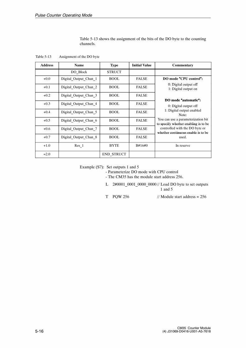
5-16CM35 Counter Module
(4) J31069-D0416-U001-A5-7618
Table 5-13 shows the assignment of the bits of the DO byte to the countingchannels.
Table 5-13 Assignment of the DO byte
Address Name Type Initial Value Commentary
DO_Block STRUCT
+0.0 Digital_Output_Chan_1 BOOL FALSE DO mode ����CPU control����:
0 Di it l t t ff+0.1 Digital_Output_Chan_2 BOOL FALSE
0: Digital output off1: Digital output on
+0.2 Digital_Output_Chan_3 BOOL FALSE
g p
DO mode ����automatic����:+0.3 Digital_Output_Chan_4 BOOL FALSE
DO mode ����automatic����:
0: Digital output off
+0.4 Digital_Output_Chan_5 BOOL FALSE
g p1: Digital output enabled
Note:
+0.5 Digital_Output_Chan_6 BOOL FALSE
Note:You can use a parameterization bitto specify whether enabling is to be
+0.6 Digital_Output_Chan_7 BOOL FALSEto specify whether enabling is to becontrolled with the DO byte or
whether continuous enable is to be+0.7 Digital_Output_Chan_8 BOOL FALSE
whether continuous enable is to beused.
+1.0 Res_1 BYTE B#16#0 In reserve
=2.0 END_STRUCT
Example (S7): Set outputs 1 and 5- Parameterize DO mode with CPU control- The CM35 has the module start address 256.
L 2#0001_0001_0000_0000 // Load DO byte to set outputs1 and 5
T PQW 256 // Module start address = 256
Pulse Counter Operating Mode
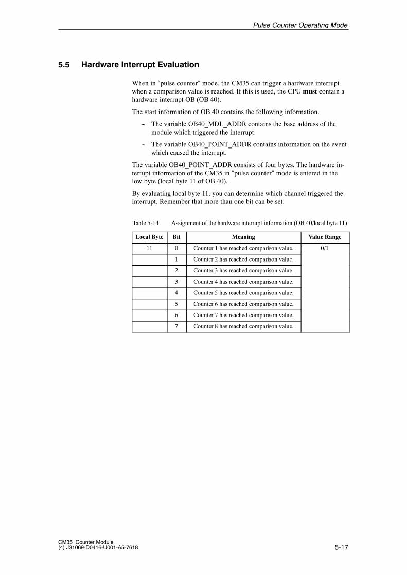
5-17CM35 Counter Module(4) J31069-D0416-U001-A5-7618
5.5 Hardware Interrupt Evaluation
When in �pulse counter� mode, the CM35 can trigger a hardware interruptwhen a comparison value is reached. If this is used, the CPU must contain ahardware interrupt OB (OB 40).
The start information of OB 40 contains the following information.
-- The variable OB40_MDL_ADDR contains the base address of themodule which triggered the interrupt.
-- The variable OB40_POINT_ADDR contains information on the eventwhich caused the interrupt.
The variable OB40_POINT_ADDR consists of four bytes. The hardware in-terrupt information of the CM35 in �pulse counter� mode is entered in thelow byte (local byte 11 of OB 40).
By evaluating local byte 11, you can determine which channel triggered theinterrupt. Remember that more than one bit can be set.
Table 5-14 Assignment of the hardware interrupt information (OB 40/local byte 11)
Local Byte Bit Meaning Value Range
11 0 Counter 1 has reached comparison value. 0/1
1 Counter 2 has reached comparison value.
2 Counter 3 has reached comparison value.
3 Counter 4 has reached comparison value.
4 Counter 5 has reached comparison value.
5 Counter 6 has reached comparison value.
6 Counter 7 has reached comparison value.
7 Counter 8 has reached comparison value.
Pulse Counter Operating Mode
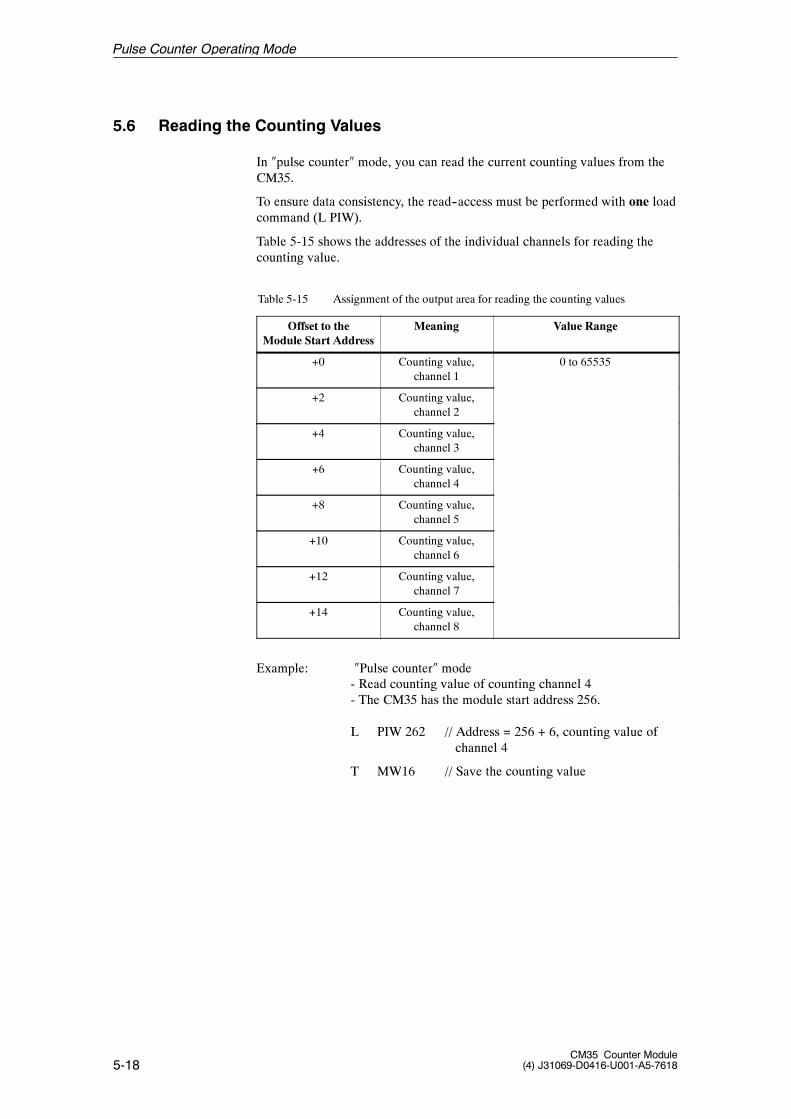
5-18CM35 Counter Module
(4) J31069-D0416-U001-A5-7618
5.6 Reading the Counting Values
In �pulse counter� mode, you can read the current counting values from theCM35.
To ensure data consistency, the read--access must be performed with one loadcommand (L PIW).
Table 5-15 shows the addresses of the individual channels for reading thecounting value.
Table 5-15 Assignment of the output area for reading the counting values
Offset to theModule Start Address
Meaning Value Range
+0 Counting value,channel 1
0 to 65535
+2 Counting value,channel 2
+4 Counting value,channel 3
+6 Counting value,channel 4
+8 Counting value,channel 5
+10 Counting value,channel 6
+12 Counting value,channel 7
+14 Counting value,channel 8
Example: �Pulse counter� mode- Read counting value of counting channel 4- The CM35 has the module start address 256.
L PIW 262 // Address = 256 + 6, counting value ofchannel 4
T MW16 // Save the counting value
Pulse Counter Operating Mode

6-1CM35 Counter Module(4) J31069-D0416-U001-A5-7618
Period Duration Measurement OperatingMode 6
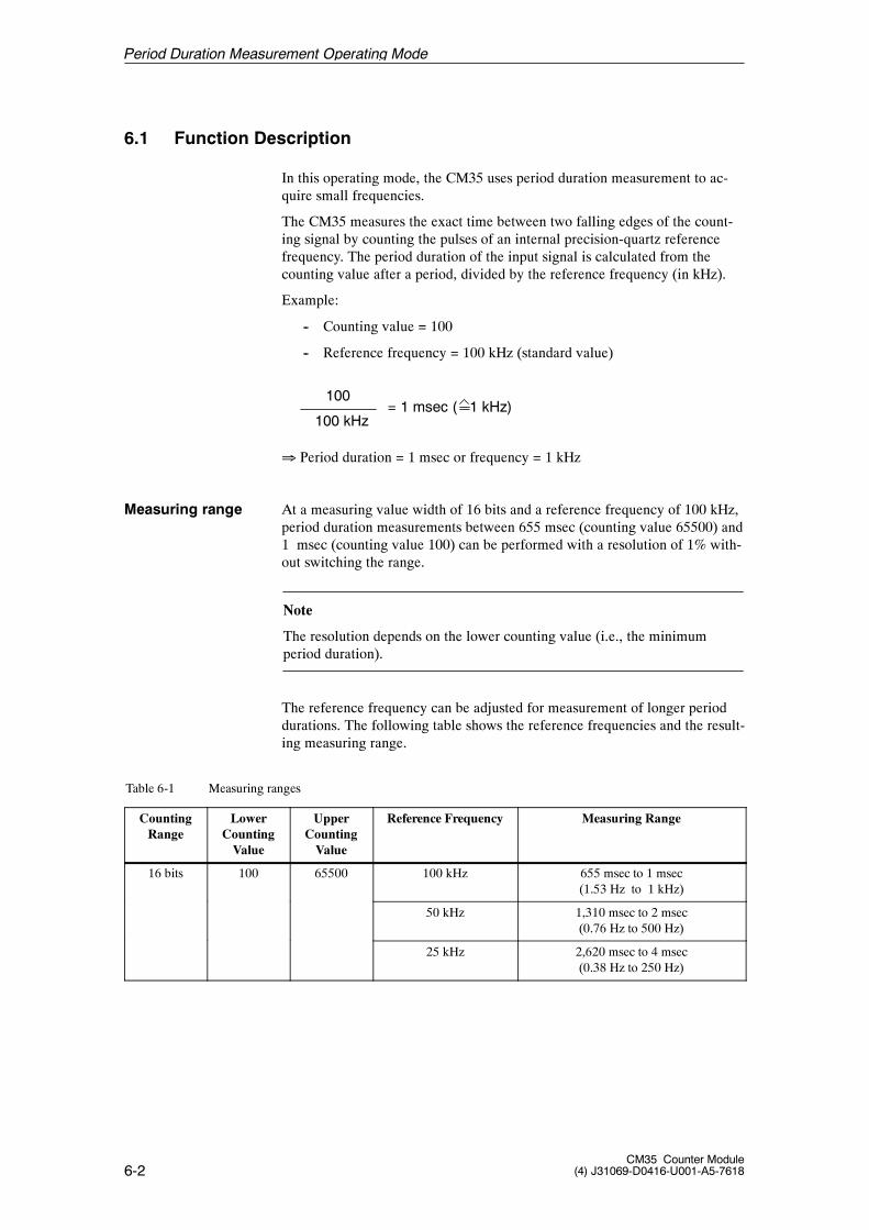
6-2CM35 Counter Module
(4) J31069-D0416-U001-A5-7618
6.1 Function Description
In this operating mode, the CM35 uses period duration measurement to ac-quire small frequencies.
The CM35 measures the exact time between two falling edges of the count-ing signal by counting the pulses of an internal precision-quartz referencefrequency. The period duration of the input signal is calculated from thecounting value after a period, divided by the reference frequency (in kHz).
Example:
-- Counting value = 100
-- Reference frequency = 100 kHz (standard value)
100
100 kHz= 1 msec ( 1 kHz)
� Period duration = 1 msec or frequency = 1 kHz
At a measuring value width of 16 bits and a reference frequency of 100 kHz,period duration measurements between 655 msec (counting value 65500) and1 msec (counting value 100) can be performed with a resolution of 1% with-out switching the range.
Note
The resolution depends on the lower counting value (i.e., the minimumperiod duration).
The reference frequency can be adjusted for measurement of longer perioddurations. The following table shows the reference frequencies and the result-ing measuring range.
Table 6-1 Measuring ranges
CountingRange
LowerCountingValue
UpperCountingValue
Reference Frequency Measuring Range
16 bits 100 65500 100 kHz 655 msec to 1 msec(1.53 Hz to 1 kHz)
50 kHz 1,310 msec to 2 msec(0.76 Hz to 500 Hz)
25 kHz 2,620 msec to 4 msec(0.38 Hz to 250 Hz)
Measuring range
Period Duration Measurement Operating Mode
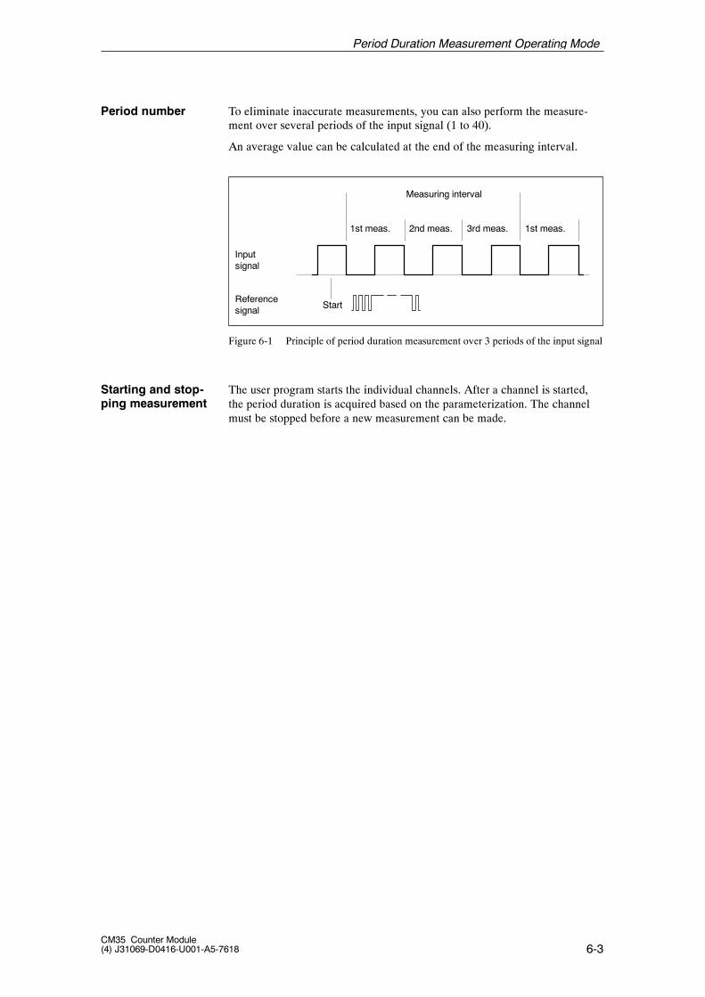
6-3CM35 Counter Module(4) J31069-D0416-U001-A5-7618
To eliminate inaccurate measurements, you can also perform the measure-ment over several periods of the input signal (1 to 40).
An average value can be calculated at the end of the measuring interval.
Inputsignal
Start
Measuring interval
Referencesignal
1st meas. 2nd meas. 3rd meas. 1st meas.
Figure 6-1 Principle of period duration measurement over 3 periods of the input signal
The user program starts the individual channels. After a channel is started,the period duration is acquired based on the parameterization. The channelmust be stopped before a new measurement can be made.
Period number
Starting and stop-ping measurement
Period Duration Measurement Operating Mode
6-4CM35 Counter Module
(4) J31069-D0416-U001-A5-7618
6.2 Parameterization
This chapter shows you available parameterizations in �period duration mea-surement� mode which you can use to adjust the reaction of the measuringchannels to your task.
The parameter data are located in a parameter block. For the structure of theparameter block, see chapter 6.2.2. The description of the individual parame-ter data includes the number of the parameter block and the offset in thestructure.
You must transfer parameter block 1 to the CM35 before you can use �periodduration measurement� mode.
Note
The channel must be stopped before it can be reparameterized.
You must stop the channel before you can change the channel--specific pa-rameters.
The new parameters take effect the next time the channel is started.
For a description of the general layout and the transmission of the parameterblock, see chapter 4.2.
Period Duration Measurement Operating Mode
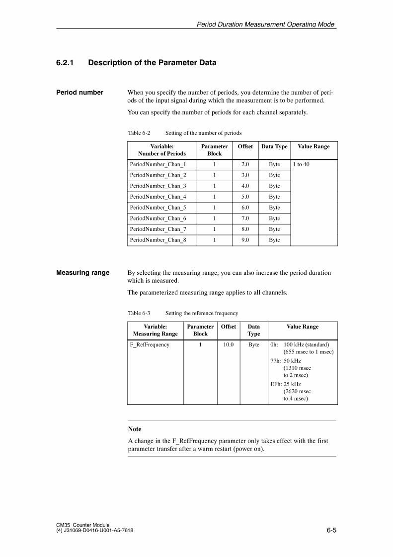
6-5CM35 Counter Module(4) J31069-D0416-U001-A5-7618
6.2.1 Description of the Parameter Data
When you specify the number of periods, you determine the number of peri-ods of the input signal during which the measurement is to be performed.
You can specify the number of periods for each channel separately.
Table 6-2 Setting of the number of periods
Variable:Number of Periods
ParameterBlock
Offset Data Type Value Range
PeriodNumber_Chan_1 1 2.0 Byte 1 to 40
PeriodNumber_Chan_2 1 3.0 Byte
PeriodNumber_Chan_3 1 4.0 Byte
PeriodNumber_Chan_4 1 5.0 Byte
PeriodNumber_Chan_5 1 6.0 Byte
PeriodNumber_Chan_6 1 7.0 Byte
PeriodNumber_Chan_7 1 8.0 Byte
PeriodNumber_Chan_8 1 9.0 Byte
By selecting the measuring range, you can also increase the period durationwhich is measured.
The parameterized measuring range applies to all channels.
Table 6-3 Setting the reference frequency
Variable:Measuring Range
ParameterBlock
Offset DataType
Value Range
F_RefFrequency 1 10.0 Byte 0h: 100 kHz (standard)(655 msec to 1 msec)
77h: 50 kHz(1310 msecto 2 msec)
EFh: 25 kHz(2620 msecto 4 msec)
Note
A change in the F_RefFrequency parameter only takes effect with the firstparameter transfer after a warm restart (power on).
Period number
Measuring range
Period Duration Measurement Operating Mode
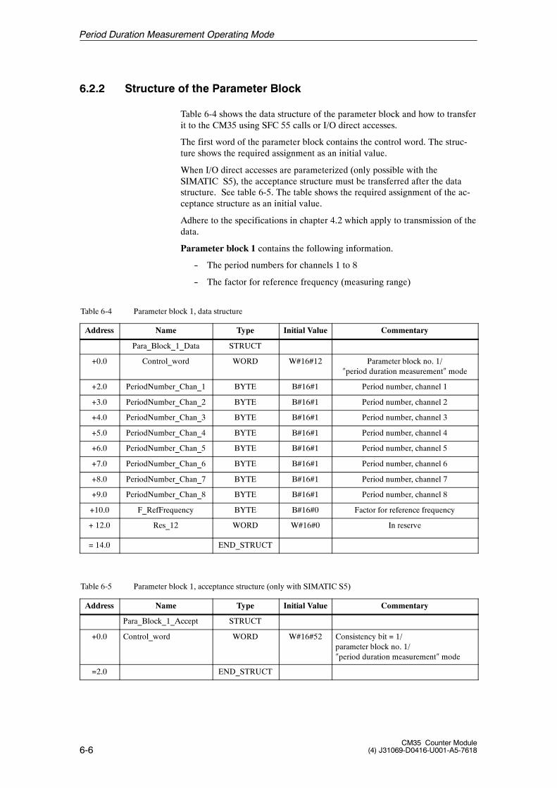
6-6CM35 Counter Module
(4) J31069-D0416-U001-A5-7618
6.2.2 Structure of the Parameter Block
Table 6-4 shows the data structure of the parameter block and how to transferit to the CM35 using SFC 55 calls or I/O direct accesses.
The first word of the parameter block contains the control word. The struc-ture shows the required assignment as an initial value.
When I/O direct accesses are parameterized (only possible with theSIMATIC S5), the acceptance structure must be transferred after the datastructure. See table 6-5. The table shows the required assignment of the ac-ceptance structure as an initial value.
Adhere to the specifications in chapter 4.2 which apply to transmission of thedata.
Parameter block 1 contains the following information.
-- The period numbers for channels 1 to 8
-- The factor for reference frequency (measuring range)
Table 6-4 Parameter block 1, data structure
Address Name Type Initial Value Commentary
Para_Block_1_Data STRUCT
+0.0 Control_word WORD W#16#12 Parameter block no. 1/�period duration measurement� mode
+2.0 PeriodNumber_Chan_1 BYTE B#16#1 Period number, channel 1
+3.0 PeriodNumber_Chan_2 BYTE B#16#1 Period number, channel 2
+4.0 PeriodNumber_Chan_3 BYTE B#16#1 Period number, channel 3
+5.0 PeriodNumber_Chan_4 BYTE B#16#1 Period number, channel 4
+6.0 PeriodNumber_Chan_5 BYTE B#16#1 Period number, channel 5
+7.0 PeriodNumber_Chan_6 BYTE B#16#1 Period number, channel 6
+8.0 PeriodNumber_Chan_7 BYTE B#16#1 Period number, channel 7
+9.0 PeriodNumber_Chan_8 BYTE B#16#1 Period number, channel 8
+10.0 F_RefFrequency BYTE B#16#0 Factor for reference frequency
+ 12.0 Res_12 WORD W#16#0 In reserve
= 14.0 END_STRUCT
Table 6-5 Parameter block 1, acceptance structure (only with SIMATIC S5)
Address Name Type Initial Value Commentary
Para_Block_1_Accept STRUCT
+0.0 Control_word WORD W#16#52 Consistency bit = 1/parameter block no. 1/�period duration measurement� mode
=2.0 END_STRUCT
Period Duration Measurement Operating Mode
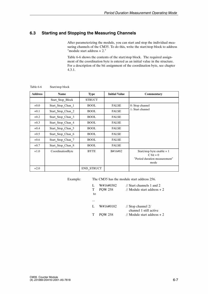
6-7CM35 Counter Module(4) J31069-D0416-U001-A5-7618
6.3 Starting and Stopping the Measuring Channels
After parameterizing the module, you can start and stop the individual mea-suring channels of the CM35. To do this, write the start/stop block to address�module start address + 2.�
Table 6-6 shows the contents of the start/stop block. The required assign-ment of the coordination byte is entered as an initial value in the structure.For a description of the bit assignment of the coordination byte, see chapter4.3.1.
Table 6-6 Start/stop block
Address Name Type Initial Value Commentary
Start_Stop_Block STRUCT
+0.0 Start_Stop_Chan_1 BOOL FALSE 0: Stop channel1 S h l
+0.1 Start_Stop_Chan_2 BOOL FALSE1: Start channel
+0.2 Start_Stop_Chan_3 BOOL FALSE
+0.3 Start_Stop_Chan_4 BOOL FALSE
+0.4 Start_Stop_Chan_5 BOOL FALSE
+0.5 Start_Stop_Chan_6 BOOL FALSE
+0.6 Start_Stop_Chan_7 BOOL FALSE
+0.7 Start_Stop_Chan_8 BOOL FALSE
+1.0 CoordinationByte BYTE B#16#82 Start/stop byte enable = 1C bit = 0
�Period duration measurement�mode
=2.0 END_STRUCT
Example: The CM35 has the module start address 256.
L W#16#0382 // Start channels 1 and 2T PQW 258 // Module start address + 2to
...
L W#16#0182 // Stop channel 2/channel 1 still active
T PQW 258 // Module start address + 2
Period Duration Measurement Operating Mode
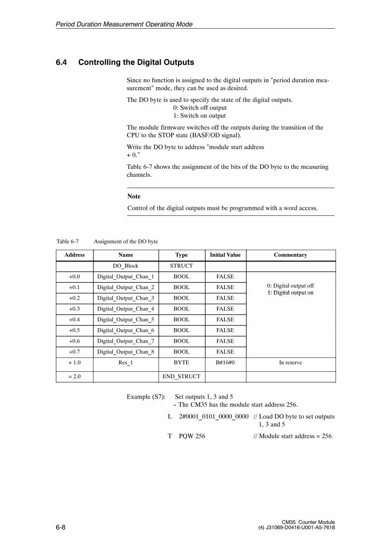
6-8CM35 Counter Module
(4) J31069-D0416-U001-A5-7618
6.4 Controlling the Digital Outputs
Since no function is assigned to the digital outputs in �period duration mea-surement� mode, they can be used as desired.
The DO byte is used to specify the state of the digital outputs.0: Switch off output1: Switch on output
The module firmware switches off the outputs during the transition of theCPU to the STOP state (BASF/OD signal).
Write the DO byte to address �module start address+ 0.�
Table 6-7 shows the assignment of the bits of the DO byte to the measuringchannels.
Note
Control of the digital outputs must be programmed with a word access.
Table 6-7 Assignment of the DO byte
Address Name Type Initial Value Commentary
DO_Block STRUCT
+0.0 Digital_Output_Chan_1 BOOL FALSE
+0.1 Digital_Output_Chan_2 BOOL FALSE 0: Digital output off1: Digital output on
+0.2 Digital_Output_Chan_3 BOOL FALSE1: Digital output on
+0.3 Digital_Output_Chan_4 BOOL FALSE
+0.4 Digital_Output_Chan_5 BOOL FALSE
+0.5 Digital_Output_Chan_6 BOOL FALSE
+0.6 Digital_Output_Chan_7 BOOL FALSE
+0.7 Digital_Output_Chan_8 BOOL FALSE
+ 1.0 Res_1 BYTE B#16#0 In reserve
= 2.0 END_STRUCT
Example (S7): Set outputs 1, 3 and 5-- The CM35 has the module start address 256.
L 2#0001_0101_0000_0000 // Load DO byte to set outputs1, 3 and 5
T PQW 256 // Module start address = 256
Period Duration Measurement Operating Mode
6-9CM35 Counter Module(4) J31069-D0416-U001-A5-7618
6.5 Hardware Interrupt Evaluation
Hardware interrupts are not generated in �period duration measurement�mode.
Period Duration Measurement Operating Mode
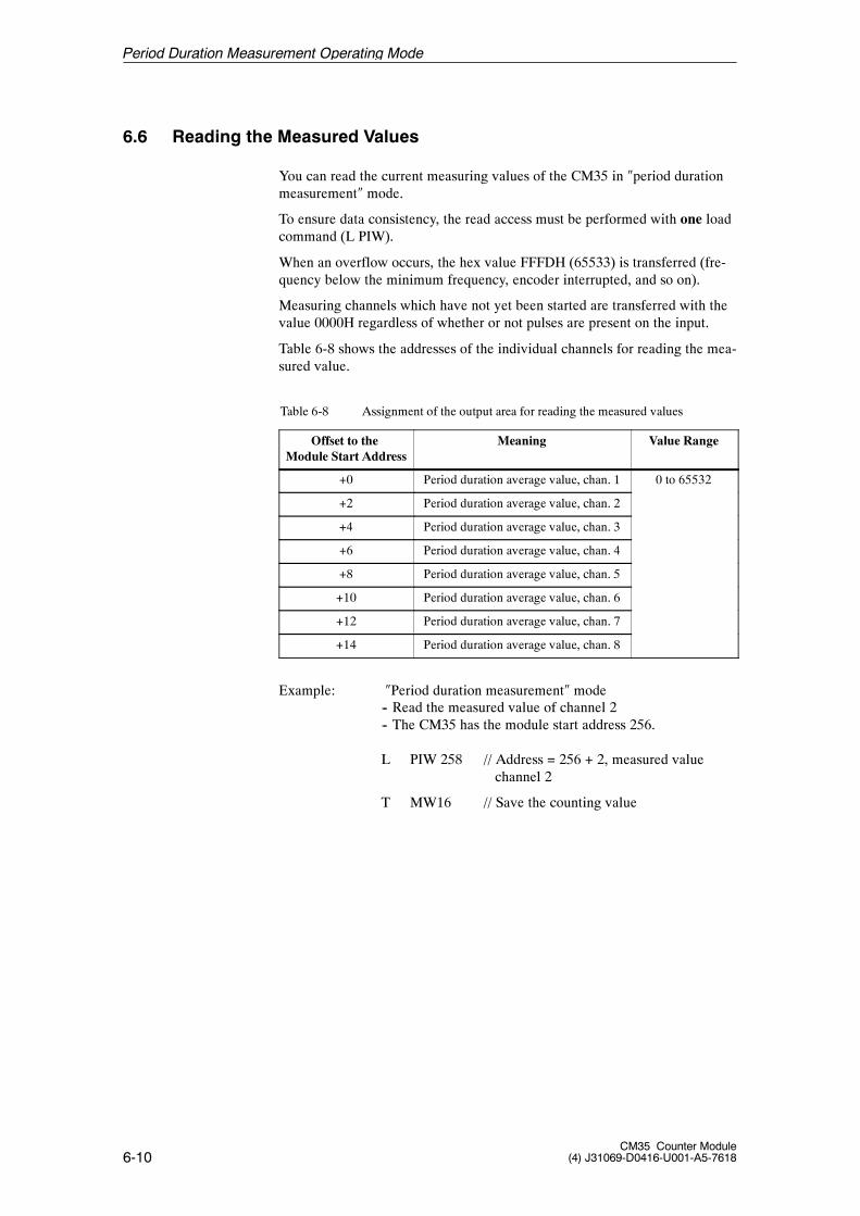
6-10CM35 Counter Module
(4) J31069-D0416-U001-A5-7618
6.6 Reading the Measured Values
You can read the current measuring values of the CM35 in �period durationmeasurement� mode.
To ensure data consistency, the read access must be performed with one loadcommand (L PIW).
When an overflow occurs, the hex value FFFDH (65533) is transferred (fre-quency below the minimum frequency, encoder interrupted, and so on).
Measuring channels which have not yet been started are transferred with thevalue 0000H regardless of whether or not pulses are present on the input.
Table 6-8 shows the addresses of the individual channels for reading the mea-sured value.
Table 6-8 Assignment of the output area for reading the measured values
Offset to theModule Start Address
Meaning Value Range
+0 Period duration average value, chan. 1 0 to 65532
+2 Period duration average value, chan. 2
+4 Period duration average value, chan. 3
+6 Period duration average value, chan. 4
+8 Period duration average value, chan. 5
+10 Period duration average value, chan. 6
+12 Period duration average value, chan. 7
+14 Period duration average value, chan. 8
Example: �Period duration measurement� mode-- Read the measured value of channel 2-- The CM35 has the module start address 256.
L PIW 258 // Address = 256 + 2, measured valuechannel 2
T MW16 // Save the counting value
Period Duration Measurement Operating Mode

7-1CM35 Counter Module(4) J31069-D0416-U001-A5-7618
Timer Operating Mode 7
7-2CM35 Counter Module
(4) J31069-D0416-U001-A5-7618
7.1 Function Description
Timer mode can be used to implement precisely defined switch--on times forthe 8 digital outputs of the counter module.
Times from 10 milliseconds to 278 minutes can be specified seperately forthe switch--on times.
The timers are started by the user program, thus setting the related digitaloutputs.
If no parameter values for time base and factor are available when a timer isstarted, these values are processed with 1 as the default value.
The related digital output is switched off after the parameterized timeexpires.A started timer can be terminated by transferring the control word with a �0�for the applicable channel in the start/stop byte. This resets the digital outputand the internal counter.
The end of the switch--on time is indicated by a hardware interrupt. This canbe acquired by the user program to trigger additional processing (e.g., toposition the next container in proportioning systems/filling systems).
A timer must be stopped before the user program can execute a new start.This can be done after the �timer expired� hardware interrupt or after a timecalculated by the user program which is with certainty longer than the runtime of the timer.
The digital outputs of the timer can also be controlled by writing the DO byte(e.g., for continuous switch--on during washing procedures). The user pro-gram must ensure that the timer channels cannot be manipulated(see chapter 7.4).
The module can monitor the switching status of its outputs. To do this, thedigital outputs must be wired to the digital inputs. The firmware cyclicallycompares the status of the digital outputs with the status of the digital inputsand generates a hardware interrupt when required by the parameterization(e.g., timer failure). The interrupt can be output as a group interrupt or as aselective interrupt (i.e., channel--specific).
Switch--on times
Start and stoptimers
Controlling theoutputs
Monitoring theoutputs
Timer Operating Mode
7-3CM35 Counter Module(4) J31069-D0416-U001-A5-7618
7.2 Parameterization
This chapter describes possible parameterization in timer mode which youcan use to adapt timer reactions to your task.
The parameter data are divided into three parameter blocks. For the structureof the parameter blocks, see chapter 7.2.2. The descriptions of the individualparameter data include the number of the parameter block and the offset inthe related structure.
To be able to utilize �timer� operating mode, you must transfer parameterblocks 1, 2 and 3 to the CM35.
Note
The timer must be stopped before it can be reparameterized.
-- When you want to change timer--specific parameters, you must stopthe applicable timer.
-- When you want to change timer--overlapping parameters, you muststop all timers.
The new parameter data take effect when the timer is started again.
For a description of the general layout and transfer of the parameter blocks,see chapter 4.2.
Timer Operating Mode
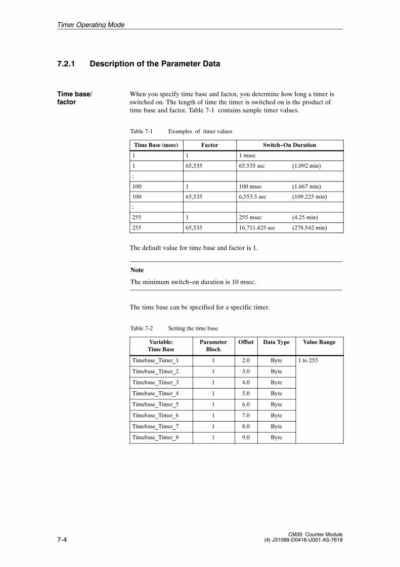
7-4CM35 Counter Module
(4) J31069-D0416-U001-A5-7618
7.2.1 Description of the Parameter Data
When you specify time base and factor, you determine how long a timer isswitched on. The length of time the timer is switched on is the product oftime base and factor. Table 7-1 contains sample timer values.
Table 7-1 Examples of timer values
Time Base (msec) Factor Switch--On Duration
1 1 1 msec
1 65,535 65.535 sec (1.092 min)
:
100 1 100 msec (1.667 min)
100 65,535 6,553.5 sec (109.225 min)
:
255 1 255 msec (4.25 min)
255 65,535 16,711.425 sec (278.542 min)
The default value for time base and factor is 1.
Note
The minimum switch--on duration is 10 msec.
The time base can be specified for a specific timer.
Table 7-2 Setting the time base
Variable:Time Base
ParameterBlock
Offset Data Type Value Range
Timebase_Timer_1 1 2.0 Byte 1 to 255
Timebase_Timer_2 1 3.0 Byte
Timebase_Timer_3 1 4.0 Byte
Timebase_Timer_4 1 5.0 Byte
Timebase_Timer_5 1 6.0 Byte
Timebase_Timer_6 1 7.0 Byte
Timebase_Timer_7 1 8.0 Byte
Timebase_Timer_8 1 9.0 Byte
Time base/factor
Timer Operating Mode
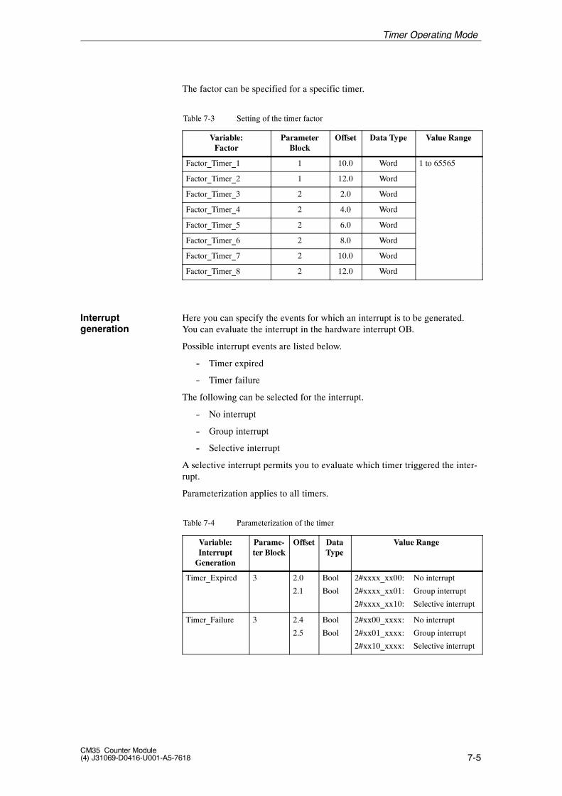
7-5CM35 Counter Module(4) J31069-D0416-U001-A5-7618
The factor can be specified for a specific timer.
Table 7-3 Setting of the timer factor
Variable:Factor
ParameterBlock
Offset Data Type Value Range
Factor_Timer_1 1 10.0 Word 1 to 65565
Factor_Timer_2 1 12.0 Word
Factor_Timer_3 2 2.0 Word
Factor_Timer_4 2 4.0 Word
Factor_Timer_5 2 6.0 Word
Factor_Timer_6 2 8.0 Word
Factor_Timer_7 2 10.0 Word
Factor_Timer_8 2 12.0 Word
Here you can specify the events for which an interrupt is to be generated.You can evaluate the interrupt in the hardware interrupt OB.
Possible interrupt events are listed below.
-- Timer expired
-- Timer failure
The following can be selected for the interrupt.
-- No interrupt
-- Group interrupt
-- Selective interrupt
A selective interrupt permits you to evaluate which timer triggered the inter-rupt.
Parameterization applies to all timers.
Table 7-4 Parameterization of the timer
Variable:InterruptGeneration
Parame-ter Block
Offset DataType
Value Range
Timer_Expired 3 2.0
2.1
Bool
Bool
2#xxxx_xx00: No interrupt
2#xxxx_xx01: Group interrupt
2#xxxx_xx10: Selective interrupt
Timer_Failure 3 2.4
2.5
Bool
Bool
2#xx00_xxxx: No interrupt
2#xx01_xxxx: Group interrupt
2#xx10_xxxx: Selective interrupt
Interruptgeneration
Timer Operating Mode
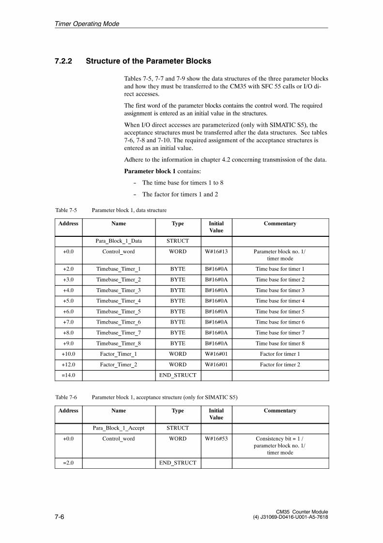
7-6CM35 Counter Module
(4) J31069-D0416-U001-A5-7618
7.2.2 Structure of the Parameter Blocks
Tables 7-5, 7-7 and 7-9 show the data structures of the three parameter blocksand how they must be transferred to the CM35 with SFC 55 calls or I/O di-rect accesses.
The first word of the parameter blocks contains the control word. The requiredassignment is entered as an initial value in the structures.
When I/O direct accesses are parameterized (only with SIMATIC S5), theacceptance structures must be transferred after the data structures. See tables7-6, 7-8 and 7-10. The required assignment of the acceptance structures isentered as an initial value.
Adhere to the information in chapter 4.2 concerning transmission of the data.
Parameter block 1 contains:
-- The time base for timers 1 to 8
-- The factor for timers 1 and 2
Table 7-5 Parameter block 1, data structure
Address Name Type InitialValue
Commentary
Para_Block_1_Data STRUCT
+0.0 Control_word WORD W#16#13 Parameter block no. 1/timer mode
+2.0 Timebase_Timer_1 BYTE B#16#0A Time base for timer 1
+3.0 Timebase_Timer_2 BYTE B#16#0A Time base for timer 2
+4.0 Timebase_Timer_3 BYTE B#16#0A Time base for timer 3
+5.0 Timebase_Timer_4 BYTE B#16#0A Time base for timer 4
+6.0 Timebase_Timer_5 BYTE B#16#0A Time base for timer 5
+7.0 Timebase_Timer_6 BYTE B#16#0A Time base for timer 6
+8.0 Timebase_Timer_7 BYTE B#16#0A Time base for timer 7
+9.0 Timebase_Timer_8 BYTE B#16#0A Time base for timer 8
+10.0 Factor_Timer_1 WORD W#16#01 Factor for timer 1
+12.0 Factor_Timer_2 WORD W#16#01 Factor for timer 2
=14.0 END_STRUCT
Table 7-6 Parameter block 1, acceptance structure (only for SIMATIC S5)
Address Name Type InitialValue
Commentary
Para_Block_1_Accept STRUCT
+0.0 Control_word WORD W#16#53 Consistency bit = 1 /parameter block no. 1/
timer mode
=2.0 END_STRUCT
Timer Operating Mode
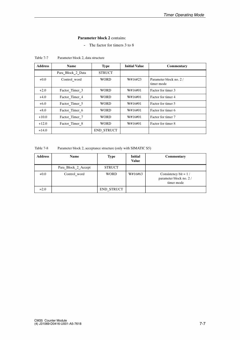
7-7CM35 Counter Module(4) J31069-D0416-U001-A5-7618
Parameter block 2 contains:
-- The factor for timers 3 to 8
Table 7-7 Parameter block 2, data structure
Address Name Type Initial Value Commentary
Para_Block_2_Data STRUCT
+0.0 Control_word WORD W#16#23 Parameter block no. 2 /timer mode
+2.0 Factor_Timer_3 WORD W#16#01 Factor for timer 3
+4.0 Factor_Timer_4 WORD W#16#01 Factor for timer 4
+6.0 Factor_Timer_5 WORD W#16#01 Factor for timer 5
+8.0 Factor_Timer_6 WORD W#16#01 Factor for timer 6
+10.0 Factor_Timer_7 WORD W#16#01 Factor for timer 7
+12.0 Factor_Timer_8 WORD W#16#01 Factor for timer 8
=14.0 END_STRUCT
Table 7-8 Parameter block 2, acceptance structure (only with SIMATIC S5)
Address Name Type InitialValue
Commentary
Para_Block_2_Accept STRUCT
+0.0 Control_word WORD W#16#63 Consistency bit = 1 /parameter block no. 2 /
timer mode
=2.0 END_STRUCT
Timer Operating Mode
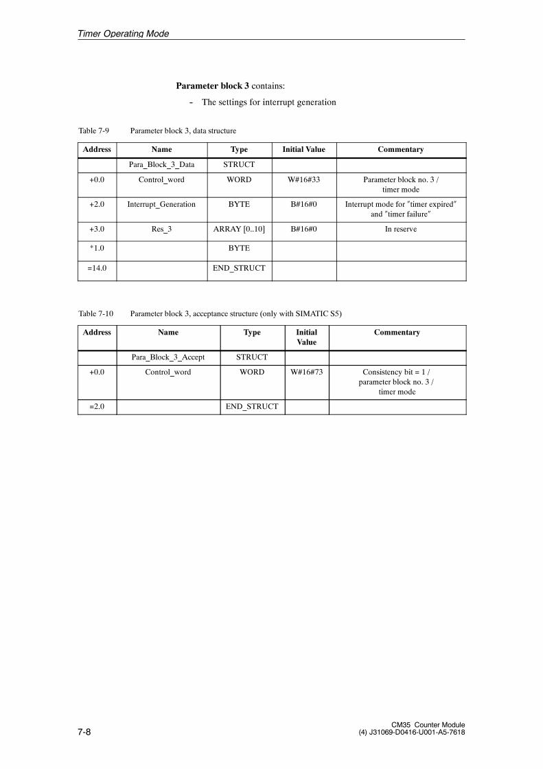
7-8CM35 Counter Module
(4) J31069-D0416-U001-A5-7618
Parameter block 3 contains:
-- The settings for interrupt generation
Table 7-9 Parameter block 3, data structure
Address Name Type Initial Value Commentary
Para_Block_3_Data STRUCT
+0.0 Control_word WORD W#16#33 Parameter block no. 3 /timer mode
+2.0 Interrupt_Generation BYTE B#16#0 Interrupt mode for �timer expired�and �timer failure�
+3.0 Res_3 ARRAY [0..10] B#16#0 In reserve
*1.0 BYTE
=14.0 END_STRUCT
Table 7-10 Parameter block 3, acceptance structure (only with SIMATIC S5)
Address Name Type InitialValue
Commentary
Para_Block_3_Accept STRUCT
+0.0 Control_word WORD W#16#73 Consistency bit = 1 /parameter block no. 3 /
timer mode
=2.0 END_STRUCT
Timer Operating Mode
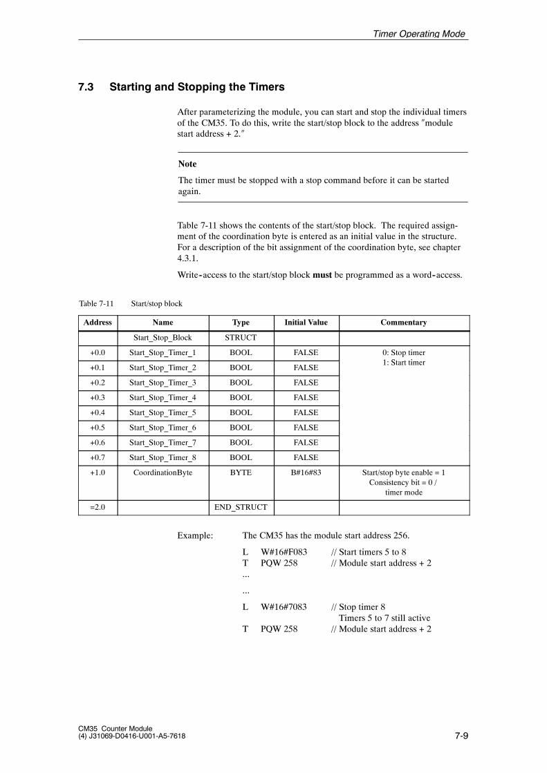
7-9CM35 Counter Module(4) J31069-D0416-U001-A5-7618
7.3 Starting and Stopping the Timers
After parameterizing the module, you can start and stop the individual timersof the CM35. To do this, write the start/stop block to the address �modulestart address + 2.�
Note
The timer must be stopped with a stop command before it can be startedagain.
Table 7-11 shows the contents of the start/stop block. The required assign-ment of the coordination byte is entered as an initial value in the structure.For a description of the bit assignment of the coordination byte, see chapter4.3.1.
Write--access to the start/stop block must be programmed as a word--access.
Table 7-11 Start/stop block
Address Name Type Initial Value Commentary
Start_Stop_Block STRUCT
+0.0 Start_Stop_Timer_1 BOOL FALSE 0: Stop timer1 S i
+0.1 Start_Stop_Timer_2 BOOL FALSE1: Start timer
+0.2 Start_Stop_Timer_3 BOOL FALSE
+0.3 Start_Stop_Timer_4 BOOL FALSE
+0.4 Start_Stop_Timer_5 BOOL FALSE
+0.5 Start_Stop_Timer_6 BOOL FALSE
+0.6 Start_Stop_Timer_7 BOOL FALSE
+0.7 Start_Stop_Timer_8 BOOL FALSE
+1.0 CoordinationByte BYTE B#16#83 Start/stop byte enable = 1Consistency bit = 0 /
timer mode
=2.0 END_STRUCT
Example: The CM35 has the module start address 256.
L W#16#F083 // Start timers 5 to 8T PQW 258 // Module start address + 2...
...
L W#16#7083 // Stop timer 8Timers 5 to 7 still active
T PQW 258 // Module start address + 2
Timer Operating Mode
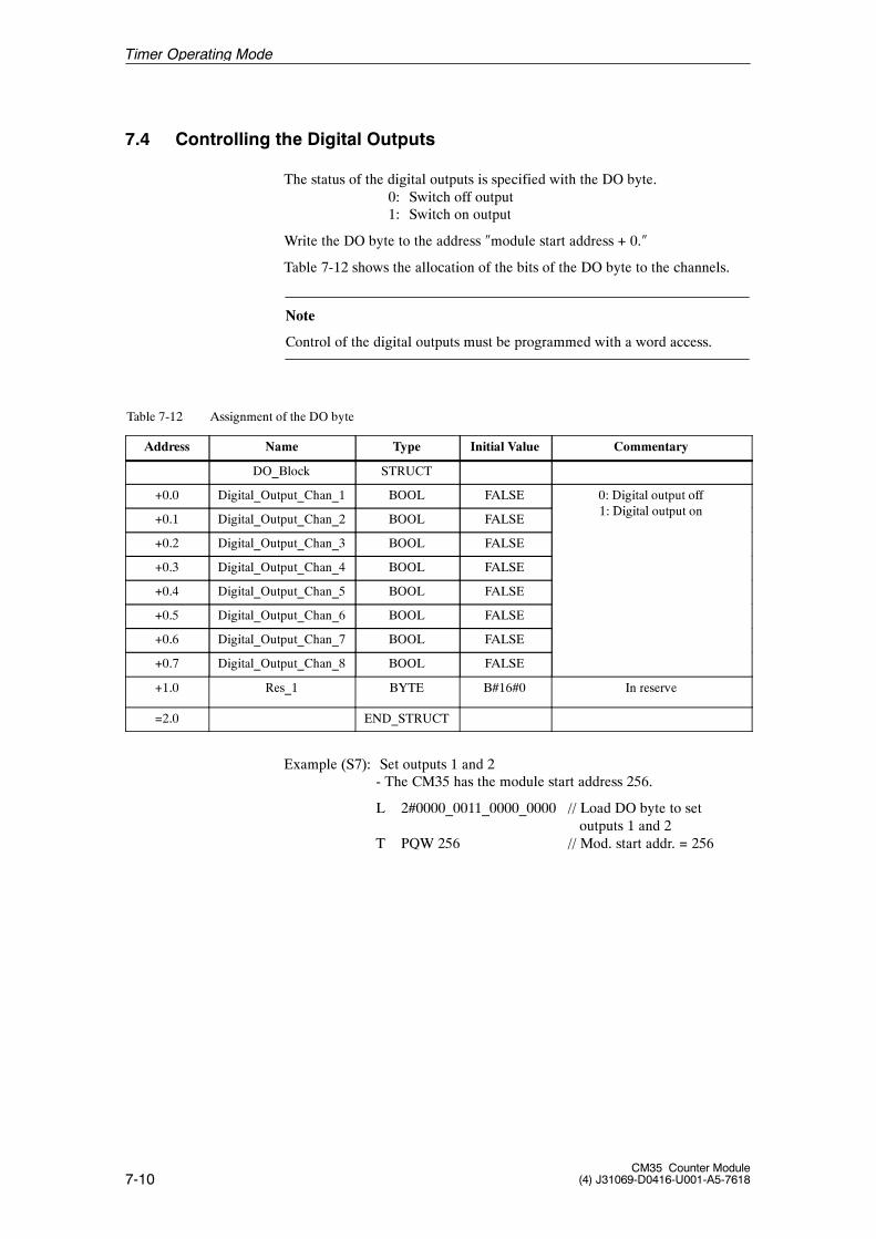
7-10CM35 Counter Module
(4) J31069-D0416-U001-A5-7618
7.4 Controlling the Digital Outputs
The status of the digital outputs is specified with the DO byte.0: Switch off output1: Switch on output
Write the DO byte to the address �module start address + 0.�
Table 7-12 shows the allocation of the bits of the DO byte to the channels.
Note
Control of the digital outputs must be programmed with a word access.
Table 7-12 Assignment of the DO byte
Address Name Type Initial Value Commentary
DO_Block STRUCT
+0.0 Digital_Output_Chan_1 BOOL FALSE 0: Digital output off1 Di i l
+0.1 Digital_Output_Chan_2 BOOL FALSE1: Digital output on
+0.2 Digital_Output_Chan_3 BOOL FALSE
+0.3 Digital_Output_Chan_4 BOOL FALSE
+0.4 Digital_Output_Chan_5 BOOL FALSE
+0.5 Digital_Output_Chan_6 BOOL FALSE
+0.6 Digital_Output_Chan_7 BOOL FALSE
+0.7 Digital_Output_Chan_8 BOOL FALSE
+1.0 Res_1 BYTE B#16#0 In reserve
=2.0 END_STRUCT
Example (S7): Set outputs 1 and 2- The CM35 has the module start address 256.
L 2#0000_0011_0000_0000 // Load DO byte to setoutputs 1 and 2
T PQW 256 // Mod. start addr. = 256
Timer Operating Mode

7-11CM35 Counter Module(4) J31069-D0416-U001-A5-7618
Note
When the digital outputs are controlled , the user program must ensure thatactive channels (timer running) are not affected.
To prevent a just expired timer from being turned on again accidentally (or arunning timer from being turned off) by control of the outputs, the outputsshould not be controlled unless all timers have expired or have been stopped.
To be noticed by the CM35, the status of the DO byte must have changed byat least one bit from its last status (see also page 4--22).
Timer Operating Mode
7-12CM35 Counter Module
(4) J31069-D0416-U001-A5-7618
7.5 Hardware Interrupt Evaluation
When in timer mode, the CM35 can trigger a hardware interrupt for thefollowing events.
-- Timer expired
-- Timer failure
The user must wire digital outputs 1 to 8 with digital inputs 1 to 8 (see chap.7.1) so that the switching status of the output can be monitored with the re-lated input. If the output setpoint state differs from the input actual state, thefollowing occurs based on the parameterization.
S No interrupt triggered
S Group interrupt triggered ! Failure of a timer
S Selective interrupt triggered ! Timer failure
The CPU must have a hardware interrupt OB (OB 40) for the interrupt evalu-ation.
The start information of OB 40 contains the following.
-- Variable OB40_MDL_ADDR contains the base address of the modulewhich triggered the interrupt.
-- Variable OB40_POINT_ADDR contains information on the eventwhich triggered the interrupt.
Variable OB40_POINT_ADDR consists of four bytes. The hardware interruptinformation of the CM35 in timer mode is stored in local byte 10 (timer fail-ure) and local byte 11 (timer expired) of OB 40.
By evaluating local bytes 10 and 11, you can tell which timer triggered aninterrupt. Remember that more than one bit can be set.
Note
When a failure occurs on one of the timers (e.g., wire break), this is reportedonce for the applicable channel with a hardware interrupt.
The reaction to the hardware interrupt (e.g., the malfunctioning timer chan-nel is no longer addressed by the user program) is specified by the user pro-gram (OB 40 call). All other timer channels remain functional.
After the malfunction is corrected (e.g., wire break fixed), a STOP/RUNtransition of the CPU must be executed. Another method is to call SFC 57�PARM_MOD.� If error correction was successful, the malfunction is nolonger reported after a STOP/RUN transition or an SFC 57 call. If the mal-function is still present, another hardware interrupt is triggered.
Timer Operating Mode
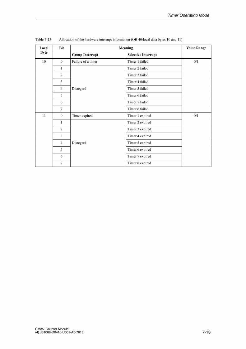
7-13CM35 Counter Module(4) J31069-D0416-U001-A5-7618
Table 7-13 Allocation of the hardware interrupt information (OB 40/local data bytes 10 and 11)
LocalB t
Bit Meaning Value RangeByte
Group Interrupt Selective Interrupt
10 0 Failure of a timer Timer 1 failed 0/1
1 Timer 2 failed
2 Timer 3 failed
3 Timer 4 failed
4 Disregard Timer 5 failed
5 Timer 6 failed
6 Timer 7 failed
7 Timer 8 failed
11 0 Timer expired Timer 1 expired 0/1
1 Timer 2 expired
2 Timer 3 expired
3 Timer 4 expired
4 Disregard Timer 5 expired
5 Timer 6 expired
6 Timer 7 expired
7 Timer 8 expired
Timer Operating Mode
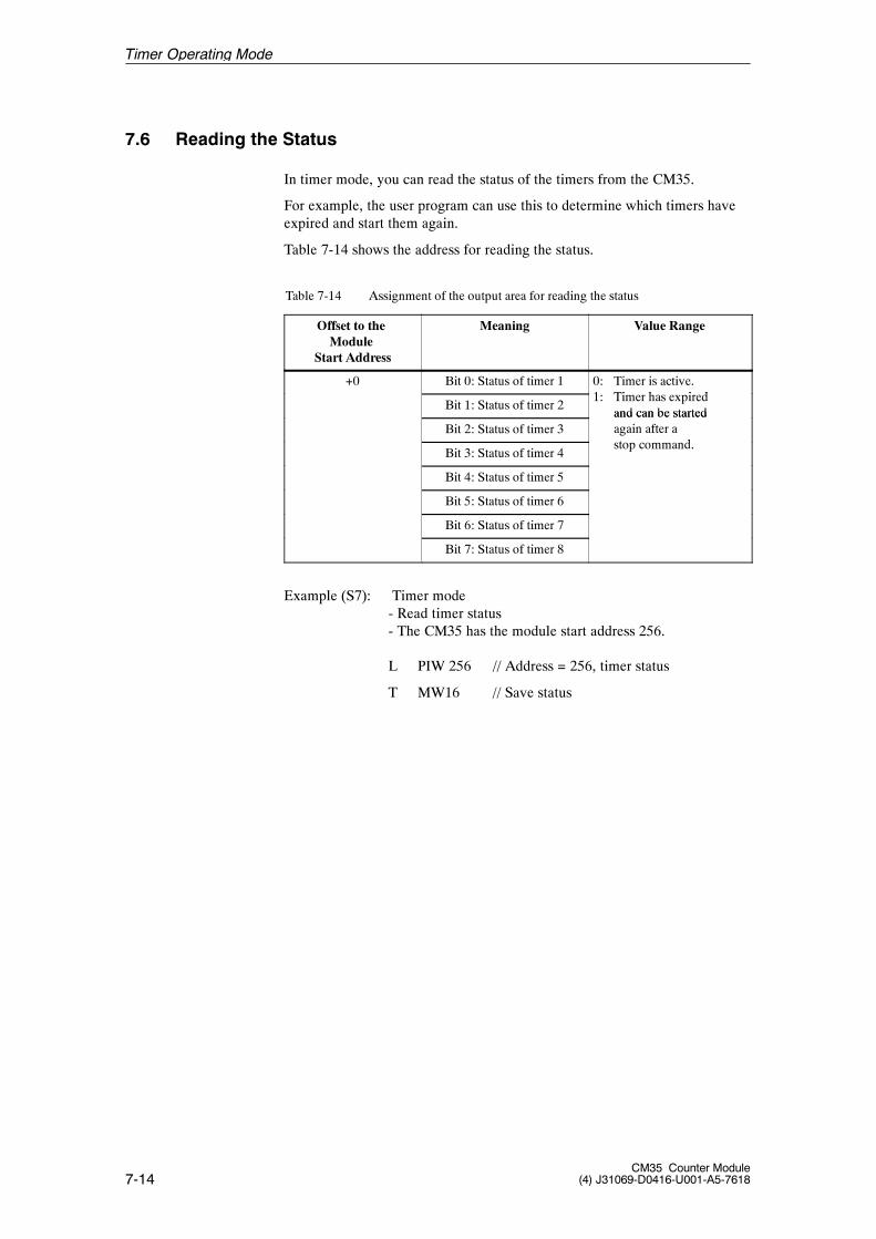
7-14CM35 Counter Module
(4) J31069-D0416-U001-A5-7618
7.6 Reading the Status
In timer mode, you can read the status of the timers from the CM35.
For example, the user program can use this to determine which timers haveexpired and start them again.
Table 7-14 shows the address for reading the status.
Table 7-14 Assignment of the output area for reading the status
Offset to theModule
Start Address
Meaning Value Range
+0 Bit 0: Status of timer 1 0: Timer is active.1 Ti h i d
Bit 1: Status of timer 21: Timer has expired
and can be startedBit 2: Status of timer 3
and can be startedagain after at d
Bit 3: Status of timer 4stop command.
Bit 4: Status of timer 5
Bit 5: Status of timer 6
Bit 6: Status of timer 7
Bit 7: Status of timer 8
Example (S7): Timer mode- Read timer status- The CM35 has the module start address 256.
L PIW 256 // Address = 256, timer status
T MW16 // Save status
Timer Operating Mode

8-1CM35 Counter Module(4) J31069-D0416-U001-A5-7618
Positioning Operating mode 8
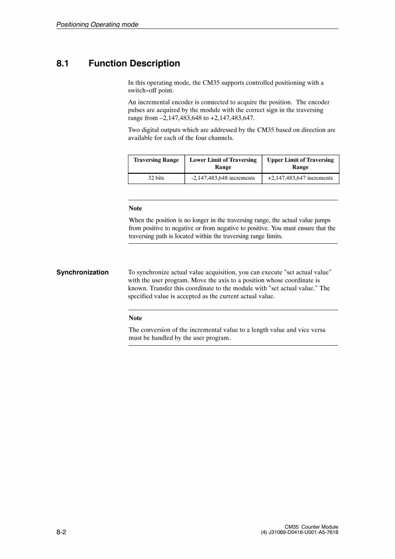
8-2CM35 Counter Module
(4) J31069-D0416-U001-A5-7618
8.1 Function Description
In this operating mode, the CM35 supports controlled positioning with aswitch--off point.
An incremental encoder is connected to acquire the position. The encoderpulses are acquired by the module with the correct sign in the traversingrange from –2,147,483,648 to +2,147,483,647.
Two digital outputs which are addressed by the CM35 based on direction areavailable for each of the four channels.
Traversing Range Lower Limit of TraversingRange
Upper Limit of TraversingRange
32 bits -2,147,483,648 increments +2,147,483,647 increments
Note
When the position is no longer in the traversing range, the actual value jumpsfrom positive to negative or from negative to positive. You must ensure that thetraversing path is located within the traversing range limits.
To synchronize actual value acquisition, you can execute �set actual value�with the user program. Move the axis to a position whose coordinate isknown. Transfer this coordinate to the module with �set actual value.� Thespecified value is accepted as the current actual value.
Note
The conversion of the incremental value to a length value and vice versamust be handled by the user program.
Synchronization
Positioning Operating mode
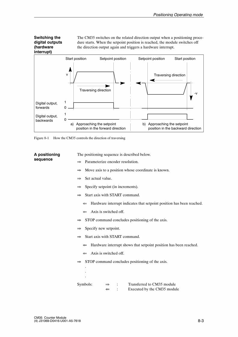
8-3CM35 Counter Module(4) J31069-D0416-U001-A5-7618
The CM35 switches on the related direction output when a positioning proce-dure starts. When the setpoint position is reached, the module switches offthe direction output again and triggers a hardware interrupt.
Digital output,forwards
Digital output,backwards
Start position Setpoint position
Traversing direction
Traversing direction
Start positionSetpoint position
1
0
1
0a) Approaching the setpoint
position in the forward directionb) Approaching the setpoint
position in the backward direction
v
-v
Figure 8-1 How the CM35 controls the direction of traversing
The positioning sequence is described below.
� Parameterize encoder resolution.
� Move axis to a position whose coordinate is known.
� Set actual value.
� Specify setpoint (in increments).
� Start axis with START command.
� Hardware interrupt indicates that setpoint position has been reached.
� Axis is switched off.
� STOP command concludes positioning of the axis.
� Specify new setpoint.
� Start axis with START command.
� Hardware interrupt shows that setpoint position has been reached.
� Axis is switched off.
� STOP command concludes positioning of the axis....
Symbols: � : Transferred to CM35 module� : Executed by the CM35 module
Switching thedigital outputs(hardwareinterrupt)
A positioningsequence
Positioning Operating mode
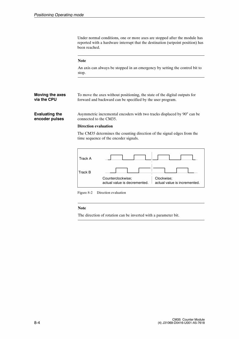
8-4CM35 Counter Module
(4) J31069-D0416-U001-A5-7618
Under normal conditions, one or more axes are stopped after the module hasreported with a hardware interrupt that the destination (setpoint position) hasbeen reached.
Note
An axis can always be stopped in an emergency by setting the control bit tostop.
To move the axes without positioning, the state of the digital outputs forforward and backward can be specified by the user program.
Asymmetric incremental encoders with two tracks displaced by 90� can beconnected to the CM35.
Direction evaluation
The CM35 determines the counting direction of the signal edges from thetime sequence of the encoder signals.
Track B
Track A
Counterclockwise;actual value is decremented.
Clockwise;actual value is incremented.
Figure 8-2 Direction evaluation
Note
The direction of rotation can be inverted with a parameter bit.
Moving the axesvia the CPU
Evaluating theencoder pulses
Positioning Operating mode
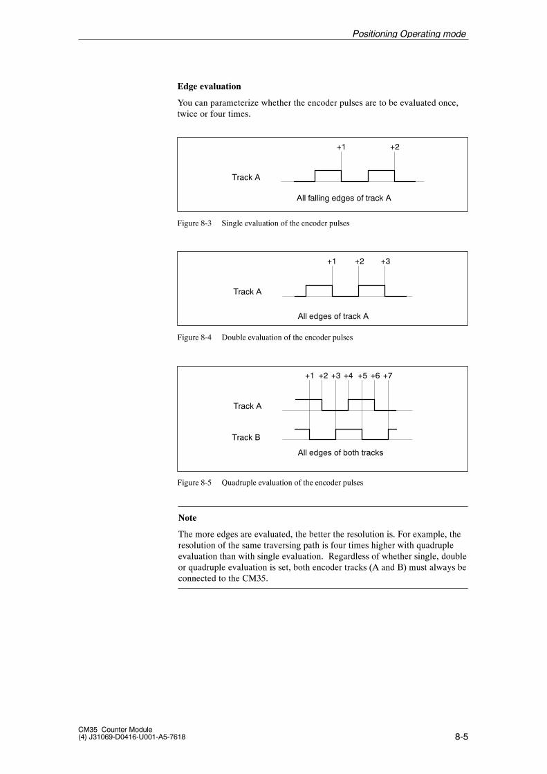
8-5CM35 Counter Module(4) J31069-D0416-U001-A5-7618
Edge evaluation
You can parameterize whether the encoder pulses are to be evaluated once,twice or four times.
+1 +2
Track A
All falling edges of track A
Figure 8-3 Single evaluation of the encoder pulses
+1 +2 +3
Track A
All edges of track A
Figure 8-4 Double evaluation of the encoder pulses
+4
Track B
Track A
All edges of both tracks
+1 +3+2 +7+6+5
Figure 8-5 Quadruple evaluation of the encoder pulses
Note
The more edges are evaluated, the better the resolution is. For example, theresolution of the same traversing path is four times higher with quadrupleevaluation than with single evaluation. Regardless of whether single, doubleor quadruple evaluation is set, both encoder tracks (A and B) must always beconnected to the CM35.
Positioning Operating mode
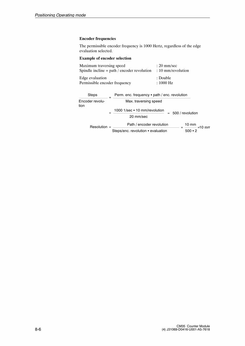
8-6CM35 Counter Module
(4) J31069-D0416-U001-A5-7618
Encoder frequencies
The permissible encoder frequency is 1000 Hertz, regardless of the edgeevaluation selected.
Example of encoder selection
Maximum traversing speed : 20 mm/secSpindle incline = path / encoder revolution : 10 mm/revolution
Edge evaluation : DoublePermissible encoder frequency : 1000 Hz
Steps Perm. enc. frequency S path / enc. revolution
Encoder revolu-tion
Max. traversing speed=
1000 1/sec S 10 mm/revolution
20 mm/sec= 500 / revolution=
ResolutionPath / encoder revolution
Steps/enc. revolution S evaluation=
10 mm= 10 mm=500 S 2
Positioning Operating mode
8-7CM35 Counter Module(4) J31069-D0416-U001-A5-7618
8.2 Parameterization
This chapter shows you how to use parameterization in positioning mode toadapt axis reaction to your task.
The parameter data are divided into nine parameter subblocks. Each parame-ter subblock must be transferred separately. For the structure of the parametersubblocks, see chapter 8.2.2. The description of the individual parameterdata includes the number of the parameter block and subblock, and the offsetin the related structure.
Note
An axis must be stopped before it can be reparameterized.
-- When you want to change an axis--specific parameter, this axis mustbe stopped.
-- When you want to change an axis--overlapping parameter, all axesmust be stopped.
The new parameters take effect when the axis is started again.
For a description of the general layout and the transmission of the parameterblocks, see chapter 4.2.
Positioning Operating mode
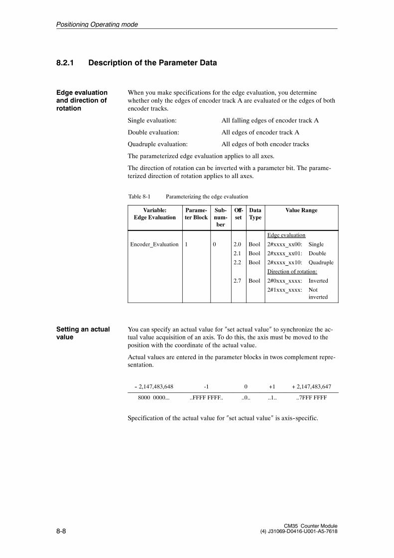
8-8CM35 Counter Module
(4) J31069-D0416-U001-A5-7618
8.2.1 Description of the Parameter Data
When you make specifications for the edge evaluation, you determinewhether only the edges of encoder track A are evaluated or the edges of bothencoder tracks.
Single evaluation: All falling edges of encoder track A
Double evaluation: All edges of encoder track A
Quadruple evaluation: All edges of both encoder tracks
The parameterized edge evaluation applies to all axes.
The direction of rotation can be inverted with a parameter bit. The parame-terized direction of rotation applies to all axes.
Table 8-1 Parameterizing the edge evaluation
Variable:Edge Evaluation
Parame-ter Block
Sub-num-ber
Off-set
DataType
Value Range
Encoder_Evaluation 1 0 2.0
2.1
2.2
2.7
Bool
Bool
Bool
Bool
Edge evaluation
2#xxxx_xx00: Single
2#xxxx_xx01: Double
2#xxxx_xx10: Quadruple
Direction of rotation:
2#0xxx_xxxx: Inverted
2#1xxx_xxxx: Notinverted
You can specify an actual value for �set actual value� to synchronize the ac-tual value acquisition of an axis. To do this, the axis must be moved to theposition with the coordinate of the actual value.
Actual values are entered in the parameter blocks in twos complement repre-sentation.
-- 2,147,483,648 -1 0 +1 + 2,147,483,647
8000 0000... ..FFFF FFFF.. ..0.. ..1.. ..7FFF FFFF
Specification of the actual value for �set actual value� is axis--specific.
Edge evaluationand direction ofrotation
Setting an actualvalue
Positioning Operating mode
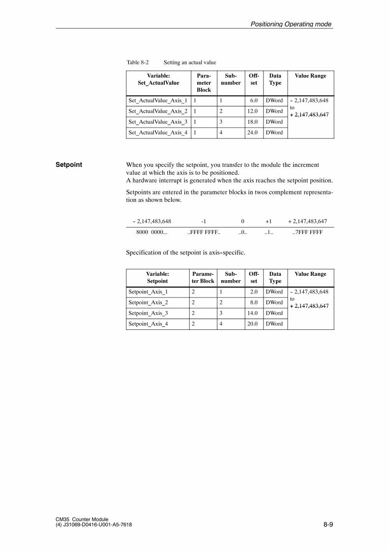
8-9CM35 Counter Module(4) J31069-D0416-U001-A5-7618
Table 8-2 Setting an actual value
Variable:Set_ActualValue
Para-meterBlock
Sub-number
Off-set
DataType
Value Range
Set_ActualValue_Axis_1 1 1 6.0 DWord -- 2,147,483,648
Set_ActualValue_Axis_2 1 2 12.0 DWordto+ 2,147,483,647
Set_ActualValue_Axis_3 1 3 18.0 DWord+ 2,147,483,647
Set_ActualValue_Axis_4 1 4 24.0 DWord
When you specify the setpoint, you transfer to the module the incrementvalue at which the axis is to be positioned.A hardware interrupt is generated when the axis reaches the setpoint position.
Setpoints are entered in the parameter blocks in twos complement representa-tion as shown below.
-- 2,147,483,648 -1 0 +1 + 2,147,483,647
8000 0000... ..FFFF FFFF.. ..0.. ..1.. ..7FFF FFFF
Specification of the setpoint is axis--specific.
Variable:Setpoint
Parame-ter Block
Sub-number
Off-set
DataType
Value Range
Setpoint_Axis_1 2 1 2.0 DWord -- 2,147,483,648
Setpoint_Axis_2 2 2 8.0 DWordto+ 2,147,483,647
Setpoint_Axis_3 2 3 14.0 DWord+ 2,147,483,647
Setpoint_Axis_4 2 4 20.0 DWord
Setpoint
Positioning Operating mode
8-10CM35 Counter Module
(4) J31069-D0416-U001-A5-7618
8.2.2 Structure of the Parameter Blocks
Tables 8-3 and 8-4 list the data structures of the nine parameter subblockswhich were combined into two parameter blocks. Each parameter subblockmust be transferred separately to the CM35 with an SFC 55 call.
The first word in the parameter subblocks contains the control word. Therequired assignment is entered as an initial value in the structures.
Adhere to the information in chapter 4.2 concerning transmission.
Positioning Operating mode
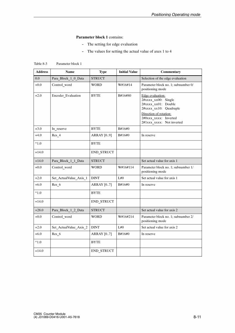
8-11CM35 Counter Module(4) J31069-D0416-U001-A5-7618
Parameter block 1 contains:
-- The setting for edge evaluation
-- The values for setting the actual value of axes 1 to 4
Table 8-3 Parameter block 1
Address Name Type Initial Value Commentary
0.0 Para_Block_1_0_Data STRUCT Selection of the edge evaluation
+0.0 Control_word WORD W#16#14 Parameter block no. 1; subnumber 0/positioning mode
+2.0 Encoder_Evaluation BYTE B#16#80 Edge evaluation:2#xxxx_xx00: Single2#xxxx_xx01: Double2#xxxx_xx10: Quadruple
Direction of rotation:2#0xxx_xxxx: Inverted2#1xxx_xxxx: Not inverted
+3.0 In_reserve BYTE B#16#0
+4.0 Res_4 ARRAY [0..9] B#16#0 In reserve
*1.0 BYTE
=14.0 END_STRUCT
+14.0 Para_Block_1_1_Data STRUCT Set actual value for axis 1
+0.0 Control_word WORD W#16#114 Parameter block no. 1; subnumber 1/positioning mode
+2.0 Set_ActualValue_Axis_1 DINT L#0 Set actual value for axis 1
+6.0 Res_6 ARRAY [0..7] B#16#0 In reserve
*1.0 BYTE
=14.0 END_STRUCT
+28.0 Para_Block_1_2_Data STRUCT Set actual value for axis 2
+0.0 Control_word WORD W#16#214 Parameter block no. 1; subnumber 2/positioning mode
+2.0 Set_ActualValue_Axis_2 DINT L#0 Set actual value for axis 2
+6.0 Res_6 ARRAY [0..7] B#16#0 In reserve
*1.0 BYTE
=14.0 END_STRUCT
Positioning Operating mode
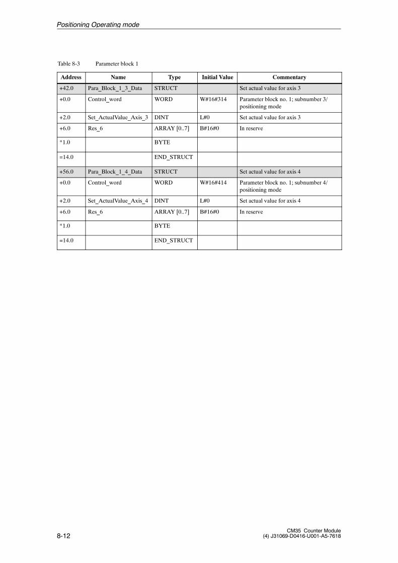
8-12CM35 Counter Module
(4) J31069-D0416-U001-A5-7618
Table 8-3 Parameter block 1
Address CommentaryInitial ValueTypeName
+42.0 Para_Block_1_3_Data STRUCT Set actual value for axis 3
+0.0 Control_word WORD W#16#314 Parameter block no. 1; subnumber 3/positioning mode
+2.0 Set_ActualValue_Axis_3 DINT L#0 Set actual value for axis 3
+6.0 Res_6 ARRAY [0..7] B#16#0 In reserve
*1.0 BYTE
=14.0 END_STRUCT
+56.0 Para_Block_1_4_Data STRUCT Set actual value for axis 4
+0.0 Control_word WORD W#16#414 Parameter block no. 1; subnumber 4/positioning mode
+2.0 Set_ActualValue_Axis_4 DINT L#0 Set actual value for axis 4
+6.0 Res_6 ARRAY [0..7] B#16#0 In reserve
*1.0 BYTE
=14.0 END_STRUCT
Positioning Operating mode
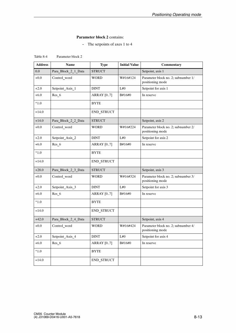
8-13CM35 Counter Module(4) J31069-D0416-U001-A5-7618
Parameter block 2 contains:
-- The setpoints of axes 1 to 4
Table 8-4 Parameter block 2
Address Name Type Initial Value Commentary
0.0 Para_Block_2_1_Data STRUCT Setpoint, axis 1
+0.0 Control_word WORD W#16#124 Parameter block no. 2; subnumber 1/positioning mode
+2.0 Setpoint_Axis_1 DINT L#0 Setpoint for axis 1
+6.0 Res_6 ARRAY [0..7] B#16#0 In reserve
*1.0 BYTE
=14.0 END_STRUCT
+14.0 Para_Block_2_2_Data STRUCT Setpoint, axis 2
+0.0 Control_word WORD W#16#224 Parameter block no. 2; subnumber 2/positioning mode
+2.0 Setpoint_Axis_2 DINT L#0 Setpoint for axis 2
+6.0 Res_6 ARRAY [0..7] B#16#0 In reserve
*1.0 BYTE
=14.0 END_STRUCT
+28.0 Para_Block_2_3_Data STRUCT Setpoint, axis 3
+0.0 Control_word WORD W#16#324 Parameter block no. 2; subnumber 3/positioning mode
+2.0 Setpoint_Axis_3 DINT L#0 Setpoint for axis 3
+6.0 Res_6 ARRAY [0..7] B#16#0 In reserve
*1.0 BYTE
=14.0 END_STRUCT
+42.0 Para_Block_2_4_Data STRUCT Setpoint, axis 4
+0.0 Control_word WORD W#16#424 Parameter block no. 2; subnumber 4/positioning mode
+2.0 Setpoint_Axis_4 DINT L#0 Setpoint for axis 4
+6.0 Res_6 ARRAY [0..7] B#16#0 In reserve
*1.0 BYTE
=14.0 END_STRUCT
Positioning Operating mode
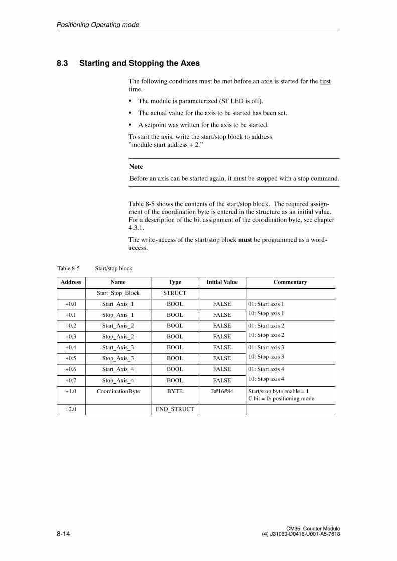
8-14CM35 Counter Module
(4) J31069-D0416-U001-A5-7618
8.3 Starting and Stopping the Axes
The following conditions must be met before an axis is started for the firsttime.
S The module is parameterized (SF LED is off).
S The actual value for the axis to be started has been set.
S A setpoint was written for the axis to be started.
To start the axis, write the start/stop block to address”module start address + 2.”
Note
Before an axis can be started again, it must be stopped with a stop command.
Table 8-5 shows the contents of the start/stop block. The required assign-ment of the coordination byte is entered in the structure as an initial value.For a description of the bit assignment of the coordination byte, see chapter4.3.1.
The write--access of the start/stop block must be programmed as a word--access.
Table 8-5 Start/stop block
Address Name Type Initial Value Commentary
Start_Stop_Block STRUCT
+0.0 Start_Axis_1 BOOL FALSE 01: Start axis 1
+0.1 Stop_Axis_1 BOOL FALSE 10: Stop axis 1
+0.2 Start_Axis_2 BOOL FALSE 01: Start axis 2
+0.3 Stop_Axis_2 BOOL FALSE 10: Stop axis 2
+0.4 Start_Axis_3 BOOL FALSE 01: Start axis 3
+0.5 Stop_Axis_3 BOOL FALSE 10: Stop axis 3
+0.6 Start_Axis_4 BOOL FALSE 01: Start axis 4
+0.7 Stop_Axis_4 BOOL FALSE 10: Stop axis 4
+1.0 CoordinationByte BYTE B#16#84 Start/stop byte enable = 1C bit = 0/ positioning mode
=2.0 END_STRUCT
Positioning Operating mode

8-15CM35 Counter Module(4) J31069-D0416-U001-A5-7618
Example: The CM35 has the module start address 256.
L W#16#4184 // Start axes 1 and 4T PQW 258 // Module start address + 2...
...
L W#16#8184 // Stop axis 4Axis 1 is not affected.
T PQW 258 // Module start address + 2
The axis stops when both bits are set to �1� or �0� for the axis.
Positioning Operating mode
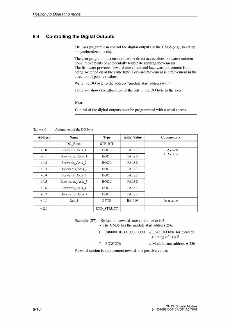
8-16CM35 Counter Module
(4) J31069-D0416-U001-A5-7618
8.4 Controlling the Digital Outputs
The user program can control the digital outputs of the CM35 (e.g., to set upor synchronize an axis).
The user program must ensure that the direct access does not cause uninten-tional movements or accidentally terminate running movements.The firmware prevents forward movement and backward movement frombeing switched on at the same time. Forward movement is a movement in thedirection of positive values.
Write the DO byte to the address �module start address + 0.�
Table 8-6 shows the allocation of the bits in the DO byte to the axes.
Note
Control of the digital outputs must be programmed with a word access.
Table 8-6 Assignment of the DO byte
Address Name Type Initial Value Commentary
DO_Block STRUCT
+0.0 Forwards_Axis_1 BOOL FALSE 0: Axis off1 A i
+0.1 Backwards_Axis_1 BOOL FALSE1: Axis on
+0.2 Forwards_Axis_2 BOOL FALSE
+0.3 Backwards_Axis_2 BOOL FALSE
+0.4 Forwards_Axis_3 BOOL FALSE
+0.5 Backwards_Axis_3 BOOL FALSE
+0.6 Forwards_Axis_4 BOOL FALSE
+0.7 Backwards_Axis_4 BOOL FALSE
+ 1.0 Res_1 BYTE B#16#0 In reserve
= 2.0 END_STRUCT
Example (S7): Switch on forward--movement for axis 2-- The CM35 has the module start address 256.
L 2#0000_0100_0000_0000 // Load DO byte for forwardrunning of axis 2
T PQW 256 // Module start address = 256
Forward motion is a movement towards the positive values.
Positioning Operating mode
8-17CM35 Counter Module(4) J31069-D0416-U001-A5-7618
Note
When controlling the digital outputs, the user program must ensure that ac-tive axes (positioning running) are not disturbed.
To prevent a just finished positioning procedure from being turned on againaccidentally (or a running positioning procedure from being turned off) dueto output control, the outputs should only be controlled when all positioningprocedures have been finished or stopped.
To be noticed by the CM35, the status of the DO byte must have changed byat least one bit from its last status (see also page 4--22).
Positioning Operating mode
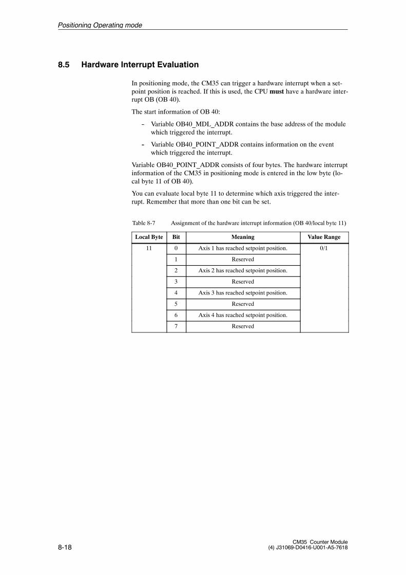
8-18CM35 Counter Module
(4) J31069-D0416-U001-A5-7618
8.5 Hardware Interrupt Evaluation
In positioning mode, the CM35 can trigger a hardware interrupt when a set-point position is reached. If this is used, the CPU must have a hardware inter-rupt OB (OB 40).
The start information of OB 40:
-- Variable OB40_MDL_ADDR contains the base address of the modulewhich triggered the interrupt.
-- Variable OB40_POINT_ADDR contains information on the eventwhich triggered the interrupt.
Variable OB40_POINT_ADDR consists of four bytes. The hardware interruptinformation of the CM35 in positioning mode is entered in the low byte (lo-cal byte 11 of OB 40).
You can evaluate local byte 11 to determine which axis triggered the inter-rupt. Remember that more than one bit can be set.
Table 8-7 Assignment of the hardware interrupt information (OB 40/local byte 11)
Local Byte Bit Meaning Value Range
11 0 Axis 1 has reached setpoint position. 0/1
1 Reserved
2 Axis 2 has reached setpoint position.
3 Reserved
4 Axis 3 has reached setpoint position.
5 Reserved
6 Axis 4 has reached setpoint position.
7 Reserved
Positioning Operating mode
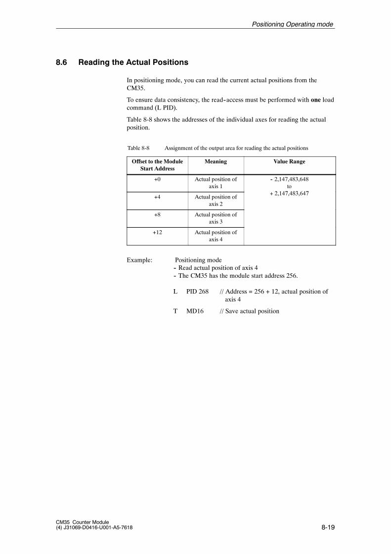
8-19CM35 Counter Module(4) J31069-D0416-U001-A5-7618
8.6 Reading the Actual Positions
In positioning mode, you can read the current actual positions from theCM35.
To ensure data consistency, the read--access must be performed with one loadcommand (L PID).
Table 8-8 shows the addresses of the individual axes for reading the actualposition.
Table 8-8 Assignment of the output area for reading the actual positions
Offset to the ModuleStart Address
Meaning Value Range
+0 Actual position ofaxis 1
-- 2,147,483,648to
2 147 483 647+4 Actual position of
axis 2
+ 2,147,483,647
+8 Actual position ofaxis 3
+12 Actual position ofaxis 4
Example: Positioning mode-- Read actual position of axis 4-- The CM35 has the module start address 256.
L PID 268 // Address = 256 + 12, actual position ofaxis 4
T MD16 // Save actual position
Positioning Operating mode

8-20CM35 Counter Module
(4) J31069-D0416-U001-A5-7618
Positioning Operating mode
A-1CM35 Counter Module(4) J31069-D0416-U001-A5-7618
Literature
Below is a list of all manuals referred to in this manual.
/70/ Manual: S7-300 Programmable Controller
/140/ Manual: ET 200M Distributed I/O Device
/231/ User’s manual: Standard Software for S7 and M7, STEP 7
/235/ Reference manual: System Software for S7-300/400 System andStandard Functions
Supplementaryliterature
A

A-2CM35 Counter Module
(4) J31069-D0416-U001-A5-7618
Literature
B-1CM35 Counter Module(4) J31069-D0416-U001-A5-7618
EC Declaration of Conformity B
B-2CM35 Counter Module
(4) J31069-D0416-U001-A5-7618
EC Declaration of Conformity
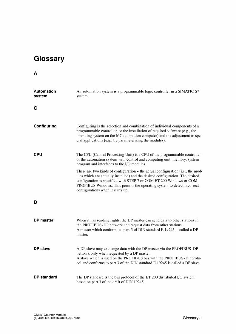
Glossary-1CM35 Counter Module(4) J31069-D0416-U001-A5-7618
Glossary
A
An automation system is a programmable logic controller in a SIMATIC S7system.
C
Configuring is the selection and combination of individual components of aprogrammable controller, or the installation of required software (e.g., theoperating system on the M7 automation computer) and the adjustment to spe-cial applications (e.g., by parameterizing the modules).
The CPU (Central Processing Unit) is a CPU of the programmable controlleror the automation system with control and computing unit, memory, systemprogram and interfaces to the I/O modules.
There are two kinds of configuration -- the actual configuration (i.e., the mod-ules which are actually installed) and the desired configuration. The desiredconfiguration is specified with STEP 7 or COM ET 200 Windows or COMPROFIBUS Windows. This permits the operating system to detect incorrectconfigurations when it starts up.
D
When it has sending rights, the DP master can send data to other stations inthe PROFIBUS--DP network and request data from other stations.A master which conforms to part 3 of DIN standard E 19245 is called a DPmaster.
A DP slave may exchange data with the DP master via the PROFIBUS--DPnetwork only when requested by a DP master.A slave which is used on the PROFIBUS bus with the PROFIBUS--DP proto-col and conforms to part 3 of the DIN standard E 19245 is called a DP slave.
The DP standard is the bus protocol of the ET 200 distributed I/O systembased on part 3 of the draft of DIN 19245.
Automationsystem
Configuring
CPU
DP master
DP slave
DP standard
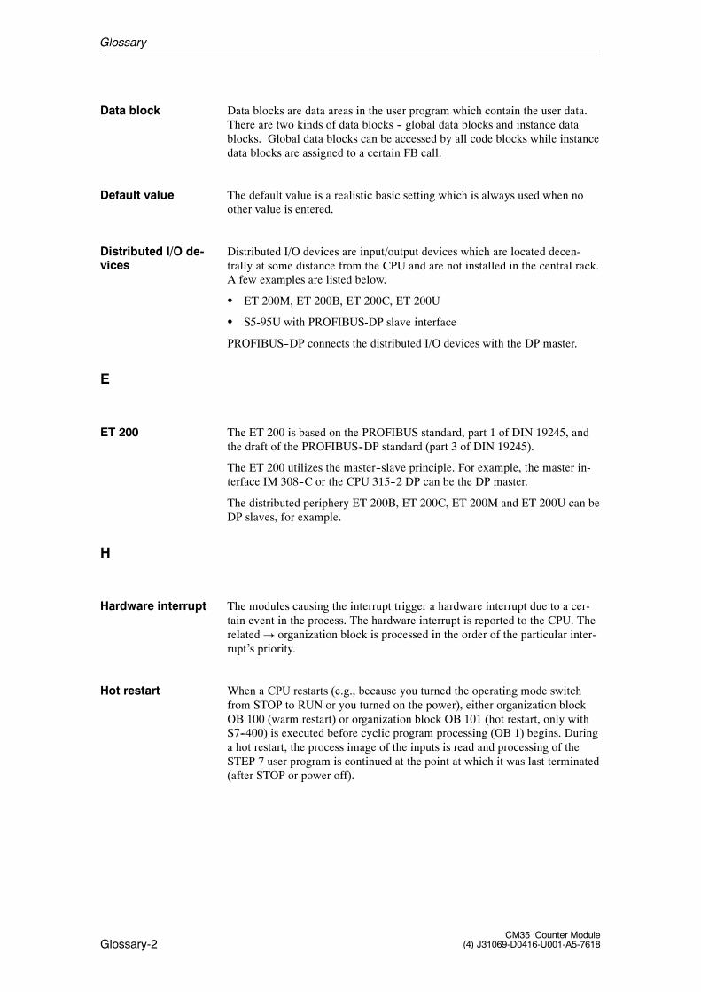
Glossary-2CM35 Counter Module
(4) J31069-D0416-U001-A5-7618
Data blocks are data areas in the user program which contain the user data.There are two kinds of data blocks -- global data blocks and instance datablocks. Global data blocks can be accessed by all code blocks while instancedata blocks are assigned to a certain FB call.
The default value is a realistic basic setting which is always used when noother value is entered.
Distributed I/O devices are input/output devices which are located decen-trally at some distance from the CPU and are not installed in the central rack.A few examples are listed below.
S ET 200M, ET 200B, ET 200C, ET 200U
S S5-95U with PROFIBUS-DP slave interface
PROFIBUS--DP connects the distributed I/O devices with the DP master.
E
The ET 200 is based on the PROFIBUS standard, part 1 of DIN 19245, andthe draft of the PROFIBUS--DP standard (part 3 of DIN 19245).
The ET 200 utilizes the master--slave principle. For example, the master in-terface IM 308--C or the CPU 315--2 DP can be the DP master.
The distributed periphery ET 200B, ET 200C, ET 200M and ET 200U can beDP slaves, for example.
H
The modules causing the interrupt trigger a hardware interrupt due to a cer-tain event in the process. The hardware interrupt is reported to the CPU. Therelated ! organization block is processed in the order of the particular inter-rupt’s priority.
When a CPU restarts (e.g., because you turned the operating mode switchfrom STOP to RUN or you turned on the power), either organization blockOB 100 (warm restart) or organization block OB 101 (hot restart, only withS7--400) is executed before cyclic program processing (OB 1) begins. Duringa hot restart, the process image of the inputs is read and processing of theSTEP 7 user program is continued at the point at which it was last terminated(after STOP or power off).
Data block
Default value
Distributed I/O de-vices
ET 200
Hardware interrupt
Hot restart
Glossary
Glossary-3CM35 Counter Module(4) J31069-D0416-U001-A5-7618
I
Incremental encoders count small increments to acquire paths, positions,speeds, revolutions, and dimensions, among others.
M
A memory reset deletes the following memory of the CPU.
S Work memory
S Read/write area of the load memory
S System memory except for the MPI parameters and the diagnostic buffer
O
Organization blocks are the interface between the CPU’s operating systemand the user program. The organization blocks specify the sequence in whichthe user program is processed.
P
1. A variable of a STEP 7 code block2. A variable which specifies the reaction of a module (one or more reactionsper module). Each module comes with a realistic basic setting. You canchange this basic setting with the STEP 7 tool HW Config.There are two kinds of parameters -- static parameters and dynamic parame-ters.
Parameterization sets the reaction of a module.
Programmable Logic Controller
PROcess FIeld BUS is the German process and fieldbus standard which isspecified in the PROFIBUS standard (DIN 19245). This standard specifiesthe functional, electrical and physical characteristics for a bit--serial fieldbussystem.
Each bus station must have an address which identifies it unambiguously toPROFIBUS.
PCs/PGs or the ET 200--Hardheld have PROFIBUS address �0.�
The DP master and the DP slaves have a PROFIBUS address from 1 to 125.
Incrementalencoder
Memory reset
Organization block(OB)
Parameter
Parameterization
PLC
PROFIBUS
PROFIBUSaddress
Glossary
Glossary-4CM35 Counter Module
(4) J31069-D0416-U001-A5-7618
PROFIBUS--DP is the PROFIBUS bus system with the DP protocol. DPstands for distributed periphery. The ET 200 peripherysystem is based on the draft of the PROFIBUS--DP standard (part 3 of DIN19245).
PROFIBUS is a bus system which networks PROFIBUS--compatible pro-grammable controllers and field devices at the cell and field level.PROFIBUS is available with the protocols DP (Distributed Periphery), FMS(Fieldbus Message Specification) or TF (Technological Functions).
The pulse duration specifies the minimum time an output must be set.
S
Signal modules (SM) provide the interface between the process and the pro-grammable controller. There are digital input and output modules, analoginput and output modules, and special SMs (e.g., the CM35).
Centralized setup means that the process periphery and CPU are located inthe same module rack or in expansion units in the same or an adjacent cabi-net.
Didtributed setup means that the process periphery is not located directlywith the CPU in the same module rack or in the same or adjacent switchingcabinet. Instead, the process periphery and the CPU are located at a distancefrom each other and are connected with a communication bus (e.g., fieldbus).
The SIMATIC Manager is the graphical user interface for SIMATIC usersunder Windows.
STARTUP is an operating mode of the CPU which covers the transition fromSTOP to RUN. STARTUP is triggered with the operating mode switch on theCPU, after power on, or by operator input on the programmer.
STEP 7 is the programming language for the creation of user programs forSIMATIC S7 controllers.
STOP is an international term (e.g., as an operating mode command).
A system function (SFC) is a function integrated in the CPU’s operatingsystem which can be called by the user program like a function block (FB).The related instance block is located in work memory.
PROFIBUS-DP
Pulse duration
Signal module
Setup, centralized
Setup,distributed
SIMATIC Manager
STARTUP
STEP 7
STOP
System function(SFC)
Glossary
Glossary-5CM35 Counter Module(4) J31069-D0416-U001-A5-7618
System errors are those errors which can occur on a programmable controller(i.e., not in the process). System errors are programming errors on the CPUand physical defects on the modules, for example.
U
The user program contains all instructions and declarations, and data forsignal processing via which a system or a process can be controlled. Thisprogram is assigned to a programmable module (e.g., CPU or FM) and can bestructured in smaller units (blocks).
W
When a CPU starts up (e.g., after you turn the operating mode switch fromSTOP to RUN or turn the power on), organization block OB 100 (warm re-start) is executed first before cyclic program processing begins (OB 1).During a warm restart, the process image of the inputs is read and the STEP 7application program is processed starting with the first command in OB 1.
System error
Userprogram
Warm restart
Glossary

Glossary-6CM35 Counter Module
(4) J31069-D0416-U001-A5-7618
Glossary

TO:
Siemens AG
A&D MC PM 4
Frauenauracher Strasse 80
D-91056 Erlangen
FROM:
Your name: _ _ _ _ _ _ _ _ _ _ _ _ _ _ _ _ _ _ _ _ _ _ _ _ _ _ _ _ _ _
Your title: _ _ _ _ _ _ _ _ _ _ _ _ _ _ _ _ _ _ _ _ _ _ _ _ _ _ _ _ _ _
Your company: _ _ _ _ _ _ _ _ _ _ _ _ _ _ _ _ _ _ _ _ _ _ _ _ _ _ _ _ _ _
Street: _ _ _ _ _ _ _ _ _ _ _ _ _ _ _ _ _ _ _ _ _ _ _ _ _ _ _ _ _
City: _ _ _ _ _ _ _ _ _ _ _ _ _ _ _ _ _ _ _ _ _ _ _ _ _ _ _ _ _ _
Telephone:_ _ _ _ _ _ _ _ _ _ _ _ _ _ _ _ _ _ _ _ _ _ _ _ _ _ _ _ _ _
Please tick your branch.
- Automotive industry
- Chemical industry
- Electrical industry
- Foodstuffs
- Process control technology
- Mechanical engineering
- Petrochemistry
- Pharmaceutics industry
- Plastics processing
- Paper industry
- Textiles industry
- Transportation industry
- Other _ _ _ _ _ _ _ _ _ _ _ _ _
If you encountered concrete problems, please use this space to explain.
_ _ _ _ _ _ _ _ _ _ _ _ _ _ _ _ _ _ _ _ _ _ _ _ _ _ _ _ _ _ _ _ _ _ _ _ _
_ _ _ _ _ _ _ _ _ _ _ _ _ _ _ _ _ _ _ _ _ _ _ _ _ _ _ _ _ _ _ _ _ _ _ _ _
_ _ _ _ _ _ _ _ _ _ _ _ _ _ _ _ _ _ _ _ _ _ _ _ _ _ _ _ _ _ _ _ _ _ _ _ _
_ _ _ _ _ _ _ _ _ _ _ _ _ _ _ _ _ _ _ _ _ _ _ _ _ _ _ _ _ _ _ _ _ _ _ _ _
_ _ _ _ _ _ _ _ _ _ _ _ _ _ _ _ _ _ _ _ _ _ _ _ _ _ _ _ _ _ _ _ _ _ _ _ _
_ _ _ _ _ _ _ _ _ _ _ _ _ _ _ _ _ _ _ _ _ _ _ _ _ _ _ _ _ _ _ _ _ _ _ _ _
_ _ _ _ _ _ _ _ _ _ _ _ _ _ _ _ _ _ _ _ _ _ _ _ _ _ _ _ _ _ _ _ _ _ _ _ _
_ _ _ _ _ _ _ _ _ _ _ _ _ _ _ _ _ _ _ _ _ _ _ _ _ _ _ _ _ _ _ _ _ _ _ _ _
_ _ _ _ _ _ _ _ _ _ _ _ _ _ _ _ _ _ _ _ _ _ _ _ _ _ _ _ _ _ _ _ _ _ _ _ _
_ _ _ _ _ _ _ _ _ _ _ _ _ _ _ _ _ _ _ _ _ _ _ _ _ _ _ _ _ _ _ _ _ _ _ _ _
_ _ _ _ _ _ _ _ _ _ _ _ _ _ _ _ _ _ _ _ _ _ _ _ _ _ _ _ _ _ _ _ _ _ _ _ _
_ _ _ _ _ _ _ _ _ _ _ _ _ _ _ _ _ _ _ _ _ _ _ _ _ _ _ _ _ _ _ _ _ _ _ _ _
Remarks/Suggestions
Your remarks and suggestions help us to improve the quality of our documentation. Pleasecomplete this questionnaire as soon as you have time, and return it to Siemens.
Title of your manual:_ _ _ _ _ _ _ _ _ _ _ _ _ _ _ _ _ _ _ _ _ _ _ _ _ _ _ _
Order number of your manual:_ _ _ _ _ _ _ _ _ _ _ _ _ _ _ _ _ _ _ _ _ _ _
Please enter your personal evaluation from 1 (good) to 5 (poor).
1. Do the contents of this manual meet your requirements ?
2. Is it easy to find the information you need ?
3. Is the information written in an easy-to-understand manner ?
4. Does the amount of technical detail meet your requirements ?
5. What is your opinion of the figures and tables ?

Siemens AGAutomation and DrivesMotion Control SystemsFrauenauracher Straße 80D-91056 Erlangen
� Siemens AG, 2000Subject to change without prior notice
Siemens Aktiengesellschaft Bestell-Nr.: J31069-D0416-U001-A5-7618Printed in the Federal Republic of Germany