simatic net 3 - siemens · simatic net industrial remote ... automation customer support under the...
TRANSCRIPT

� �TELECONTROL SERVER BASIC
___________________
___________________
___________________
___________________
___________________
___________________
___________________
______________________________
SIMATIC NET
Industrial Remote Communication Telecontrol TELECONTROL SERVER BASIC
Operating Instructions
07/2013 C79000-G8976-C249-05
Preface
Application and properties 1
Installation and commissioning
2
The OPC server 3
Notes on configuration and operation
4
The Configuration and Monitoring Tool
5
Automated installation A
Examples of the configuration data of SMS gateway providers
B
References C

Siemens AG Industry Sector Postfach 48 48 90026 NÜRNBERG GERMANY
Order number: C79000-G8976-C249 Ⓟ 07/2013 Technical data subject to change
Copyright © Siemens AG 2011 - 2013.All rights reserved
Legal information Warning notice system
This manual contains notices you have to observe in order to ensure your personal safety, as well as to prevent damage to property. The notices referring to your personal safety are highlighted in the manual by a safety alert symbol, notices referring only to property damage have no safety alert symbol. These notices shown below are graded according to the degree of danger.
DANGER indicates that death or severe personal injury will result if proper precautions are not taken.
WARNING indicates that death or severe personal injury may result if proper precautions are not taken.
CAUTION indicates that minor personal injury can result if proper precautions are not taken.
NOTICE indicates that property damage can result if proper precautions are not taken.
If more than one degree of danger is present, the warning notice representing the highest degree of danger will be used. A notice warning of injury to persons with a safety alert symbol may also include a warning relating to property damage.
Qualified Personnel The product/system described in this documentation may be operated only by personnel qualified for the specific task in accordance with the relevant documentation, in particular its warning notices and safety instructions. Qualified personnel are those who, based on their training and experience, are capable of identifying risks and avoiding potential hazards when working with these products/systems.
Proper use of Siemens products Note the following:
WARNING Siemens products may only be used for the applications described in the catalog and in the relevant technical documentation. If products and components from other manufacturers are used, these must be recommended or approved by Siemens. Proper transport, storage, installation, assembly, commissioning, operation and maintenance are required to ensure that the products operate safely and without any problems. The permissible ambient conditions must be complied with. The information in the relevant documentation must be observed.
Trademarks All names identified by ® are registered trademarks of Siemens AG. The remaining trademarks in this publication may be trademarks whose use by third parties for their own purposes could violate the rights of the owner.
Disclaimer of Liability We have reviewed the contents of this publication to ensure consistency with the hardware and software described. Since variance cannot be precluded entirely, we cannot guarantee full consistency. However, the information in this publication is reviewed regularly and any necessary corrections are included in subsequent editions.

TELECONTROL SERVER BASIC Operating Instructions, 07/2013, C79000-G8976-C249-05 3
Preface
Purpose of this documentation This manual supports you during the configuration, installation, commissioning and operation of the TELECONTROL SERVER BASIC application.
Validity of the documentation This manual applies to the following software versions:
TELECONTROL SERVER BASIC Version V2.0 + Service Pack 3
The product is available with the following expansions
Product name Order number Number of connectable
stations TELECONTROL SERVER BASIC 8 6NH9910-0AA20-0AA0 8 TELECONTROL SERVER BASIC 32 6NH9910-0AA20-0AF0 32 TELECONTROL SERVER BASIC 64 6NH9910-0AA20-0AB0 64 TELECONTROL SERVER BASIC 256 6NH9910-0AA20-0AC0 256 TELECONTROL SERVER BASIC 1000 6NH9910-0AA20-0AD0 1000 TELECONTROL SERVER BASIC 5000 6NH9910-0AA20-0AE0 5000
Abbreviations/acronyms ● CMT
The "Configuration and Monitoring Tool", the configuration and monitoring user interface of TCSB is also abbreviated to "CMT" in the remainder of the manual.
● CP
CP 1242-7
● TCSB
In the remainder of the manual, the "TELECONTROL SERVER BASIC " software is also abbreviated to "TCSB".
New in this release ● New software version V2.0 + Service Pack 3
● New operating systems for the telecontrol server (see section Installation and commissioning (Page 17))
● Editorial revision

Preface
TELECONTROL SERVER BASIC 4 Operating Instructions, 07/2013, C79000-G8976-C249-05
Replaced documentation This manual replaces the manual release 03/2013.
Required experience To be able to configure and operate the system described in this document, you require experience of the following products, systems and technologies:
● SIMATIC S7
● SIMATIC NET / Telecontrol
● STEP 7 Basic V12
● IP-based communication
Current manual release on the Internet You will also find the current version of this manual on the Internet pages of Siemens Automation Customer Support under the following entry ID:
50898745 (http://support.automation.siemens.com/WW/view/en/50898745)
Further information on the Internet You will find further information on the Siemens telecontrol products such as the latest information, manuals, FAQs or software updates on the Internet on the pages of Siemens Automation Customer Support under the following entry ID:
46635999 (http://support.automation.siemens.com/WW/view/en/46635999)
There select the required information under "Entry type" (for example "Updates", "Manuals", "FAQs" etc.).
Examples of applications on the Internet You will find various examples of applications on the Internet on the pages of Siemens Automation Customer Support under the entry IDs listed below.
● Example of an application for wireless direct communication and inter-station communication of S7 stations with a CP 1242-7:
58099765 (http://support.automation.siemens.com/WW/view/en/58099765)
39863979 (http://support.automation.siemens.com/WW/view/en/39863979)
58638283 (http://support.automation.siemens.com/WW/view/en/58638283)
● Example of an application for TeleService access by an engineering station to an S7 station with a CP 1242-7 via the Internet:
56720905 (http://support.automation.siemens.com/WW/view/en/56720905)
● Example of an application for connecting an S7-300 to SINAUT Micro SC or TELECONTROL SERVER BASIC:
27038105 (http://support.automation.siemens.com/WW/view/en/27038105)

Preface
TELECONTROL SERVER BASIC Operating Instructions, 07/2013, C79000-G8976-C249-05 5
SIMATIC NET glossary Explanations of the specialist terms used in this documentation can be found in the SIMATIC NET glossary.
You will find the SIMATIC NET glossary here:
● SIMATIC NET Manual Collection
The DVD ships with certain SIMATIC NET products.
● On the Internet under the following entry ID:
50305045 (http://support.automation.siemens.com/WW/view/en/50305045)
Training, Service & Support You will find information on Training, Service & Support in the multi--language document "DC_support_99.pdf" on the data medium supplied with the documentation.
Security information Siemens provides automation and drive products with industrial security functions that support the secure operation of plants or machines. They are an important component in a holistic industrial security concept. With this in mind, our products undergo continuous development. We therefore recommend that you keep yourself informed with respect to our product updates. Please find further information and newsletters on this subject at: http://support.automation.siemens.com.
To ensure the secure operation of a plant or machine it is also necessary to take suitable preventive action (e.g. cell protection concept) and to integrate the automation and drive components into a state-of-the-art holistic industrial security concept for the entire plant or machine. Any third-party products that may be in use must also be taken into account. Please find further information at: http://www.siemens.com/industrialsecurity

Preface
TELECONTROL SERVER BASIC 6 Operating Instructions, 07/2013, C79000-G8976-C249-05

TELECONTROL SERVER BASIC Operating Instructions, 07/2013, C79000-G8976-C249-05 7
Table of contents
Preface ...................................................................................................................................................... 3
1 Application and properties ......................................................................................................................... 9
1.1 Application......................................................................................................................................9
1.2 Subcomponents of TCSB ............................................................................................................11
1.3 Installation options for TCSB .......................................................................................................11
1.4 Properties and configuration limits...............................................................................................12
1.5 Configuration examples ...............................................................................................................14
2 Installation and commissioning ................................................................................................................ 17
2.1 Required devices, software, licenses and information ................................................................17
2.2 Installation of the TCSB software.................................................................................................19
2.3 Changing the port, network and DCOM settings .........................................................................22
2.4 Uninstalling...................................................................................................................................23
3 The OPC server....................................................................................................................................... 25
3.1 The OPC server of TCSB ............................................................................................................25
3.2 Process OPC items......................................................................................................................26
3.3 System OPC items.......................................................................................................................29
3.4 Multicast OPC items ....................................................................................................................32
3.5 Status OPC items ........................................................................................................................33
3.6 Name space of the OPC server ...................................................................................................34
4 Notes on configuration and operation ...................................................................................................... 37
4.1 Overview of configuration ............................................................................................................37
4.2 Working with projects...................................................................................................................38
4.3 The user concept .........................................................................................................................39
4.4 Inter-station communication.........................................................................................................39
4.5 Program blocks for the CPU ........................................................................................................40
4.6 TeleService functions...................................................................................................................40
4.7 Increasing the availability of the system ......................................................................................40
4.8 Main and substitute telecontrol server .........................................................................................40
4.9 Connection establishment............................................................................................................42
4.10 Wake-up SMS for the CP 1242-7 ................................................................................................43
4.11 Redial delay of the CP 1242-7 (STEP 7) .....................................................................................44

Table of contents
TELECONTROL SERVER BASIC 8 Operating Instructions, 07/2013, C79000-G8976-C249-05
4.12 Monitoring times of connected OPC clients ................................................................................ 45
4.13 Monitoring the connections (CP 1242-7) .................................................................................... 45
4.14 Data management in the process images .................................................................................. 47 4.14.1 Data management for communication with S7-200 stations ...................................................... 47 4.14.2 Data management in the process images of the CP 1242-7 (V1.x) ........................................... 47
4.15 Times of day in the system ......................................................................................................... 49
4.16 Overview of the passwords......................................................................................................... 49
5 The Configuration and Monitoring Tool.................................................................................................... 51
5.1 Overview of functions.................................................................................................................. 51
5.2 Starting the CMT ......................................................................................................................... 52
5.3 The CMT window ........................................................................................................................ 54 5.3.1 Layout of the window .................................................................................................................. 54 5.3.2 Menu bar ..................................................................................................................................... 58 5.3.3 Individual adaptation of the window............................................................................................ 59 5.3.4 Online help .................................................................................................................................. 60
5.4 Configuring and monitoring......................................................................................................... 60 5.4.1 Creating and deleting projects .................................................................................................... 60 5.4.2 Configuring and activating projects............................................................................................. 65 5.4.3 Importing projects........................................................................................................................ 68 5.4.4 Creating and deleting connections.............................................................................................. 69 5.4.5 Configuring connections, waking up a station............................................................................. 77 5.4.6 "Activated parameters" area ....................................................................................................... 82 5.4.7 TeleService connections ............................................................................................................. 82 5.4.8 Setting up users and administrators ........................................................................................... 83 5.4.9 Access permissions .................................................................................................................... 86 5.4.10 User data..................................................................................................................................... 88 5.4.11 Configuring inter-station communication..................................................................................... 88 5.4.12 Configuring SMS gateway providers........................................................................................... 90 5.4.13 Settings ....................................................................................................................................... 93
5.5 Diagnostics and statistical data (system variables) .................................................................... 97
A Automated installation ........................................................................................................................... 101
B Examples of the configuration data of SMS gateway providers ............................................................. 105
C References ............................................................................................................................................ 107
Index...................................................................................................................................................... 109

TELECONTROL SERVER BASIC Operating Instructions, 07/2013, C79000-G8976-C249-05 9
Application and properties 11.1 Application
Using the TELECONTROL SERVER BASIC software The TELECONTROL SERVER BASIC (TCSB) software connects up to 5000 SIMATIC S7 controllers via the mobile wireless standard GSM/GPRS to an OPC interface. This means that widely distributed telecontrol solutions can be implemented in a variety of different sectors and applications.
The database-supported software allows distributed engineering and the management of many projects on one server.
For the S7-1200 with a CP 1242-7, TeleService via GPRS and the Internet is supported.
The "Telecontrol server" The TCSB software is installed on a PC connected to the telecontrol network. The PC on which the TCSB software is installed is known as the "telecontrol server".
You will find the compatible operating systems for this PC in the section Required devices, software, licenses and information (Page 17).
Connectable SIMATIC S7 systems The following SIMATIC S7 systems of a telecontrol network can be connected with the software:
● SIMATIC S7-200 with SINAUT MD720-3 modem
● SIMATIC S7-1200 with CP 1242-7
For project-specific solutions with SIMATIC S7-300, please contact Siemens Automation Customer Support. You will find the link to the document with the contact data of Customer Support in the Preface (Page 3) of this manual.
Telecontrol applications ● Communication based on the mobile wireless service GPRS (General Packet Radio
Service)
● Operating the SIMATIC S7 independent of individual mobile wireless providers via standard APNs (mobile wireless - Internet access) with normal mobile phone contracts
● GPRS operation of the SIMATIC S7 via private APNs (mobile wireless - network access) of the mobile wireless providers for the greatest security

Application and properties 1.1 Application
TELECONTROL SERVER BASIC 10 Operating Instructions, 07/2013, C79000-G8976-C249-05
● Central status monitoring of the connected S7 stations
● Linking of the telecontrol stations to a control center via the OPC-DA interface of the integrated OPC server
TeleService applications (S7-1200) ● TeleService from S7-1200 stations with CP 1242-7 from an engineering station via the
telecontrol server over Internet and GPRS
– Downloading project or program data from the STEP 7 project to the station
– Querying diagnostics data on the station
Protection concept To protect the system from unauthorized access and therefore also to avoid transmission costs associated with such access, system access is protected in several ways:
● Users and passwords
The editors are assigned various roles. Access is password protected. You will find an overview of the passwords in the section Overview of the passwords (Page 49).
● User permissions
Different permissions and rights are assigned to the various user types. You will find details in the section Access permissions (Page 86).
● Authorized phone numbers
Access to stations of the type S7-1200 with CP 1242-7 is restricted to telephone numbers stored in the CP configuration. See also section Configuring SMS gateway providers (Page 90).

Application and properties 1.2 Subcomponents of TCSB
TELECONTROL SERVER BASIC Operating Instructions, 07/2013, C79000-G8976-C249-05 11
1.2 Subcomponents of TCSB
Main components of TCSB TCSB is made up of the following main components:
● Telecontrol Manager
The Telecontrol Manager manages the connections with communications partners. This is the communications center of all connected software components in the PC side and the process side. It controls the frames between the sender and destination address and has the logical connection information, system variables and configuration information.
The Telecontrol Manager is not visible to the user. The configuration of the access data is created using the CMT (see below).
● Database
Stores the data of the system. The database is not visible to the user. The user interface to the database is CMT (see below).
The database has separate areas for the offline configuration data and for the online configuration data of the runtime system.
● OPC server
The OPC server integrated in TCSB provides the data of the stations connected via GPRS to a connected OPC client.
● Configuration and Monitoring Tool (CMT)
The CMT is the program user interface with the following main functions:
– Configuration of the system and the connections to the stations
– Monitoring of the connections
1.3 Installation options for TCSB
Installation of the single system on one or more computers You can install TCSB on a single or on multiple computers:
● Installation on only one computer
All the functions of TCSB on one computer (telecontrol server).
● Installation on several computers
The functions of TCSB can be distributed:
– Telecontrol Manager, database and OPC server on one computer (telecontrol server)
– The Configuration and Monitoring Tool (CMT) for configuration and monitoring of the telecontrol system on other separate computers

Application and properties 1.4 Properties and configuration limits
TELECONTROL SERVER BASIC 12 Operating Instructions, 07/2013, C79000-G8976-C249-05
Installation as main and substitute server When TCSB is installed as a main and substitute server, two separate systems work side by side. If the main system cannot be reached, the remote S7-1200 with a CP 1242-7 switches over to the substitute system.
Details on the functions can be found in the section Main and substitute telecontrol server (Page 40).
1.4 Properties and configuration limits
Properties ● Communication with telecontrol stations
– Connecting to the GSM network via standard APNs (mobile wireless - Internet access)
– Connection to the Internet via private APNs
– Using the GPRS service in the GSM network
● Number of possible connections
– Max. 5 000
– Connections can be distributed in up to 2 000 projects
● Support of large applications
– Multiproject capability
It is possible to manage multiple telecontrol projects.
– Assignment of rights
Users can be assigned to different projects.
– Multiuser system
Several users can configure at the same time.
● Monitoring of the connected stations
– Group diagnostics of a single overall project
– Keepalive monitoring
– Status monitoring of the connection
The result of all these monitoring functions is displayed in the CMT and made available to connected OPC clients as system items.
● Inter-station communication
Forwarding of frames from S7-1200 stations to other S7-1200 stations via the Internet and GSM

Application and properties 1.4 Properties and configuration limits
TELECONTROL SERVER BASIC Operating Instructions, 07/2013, C79000-G8976-C249-05 13
● Optimized power requirements and minimized data volumes
– Establishment of GPRS connections only when required (temporary connections)
– Low data volumes due to event-oriented data transfer and optimized monitoring functions for permanent connections
● OPC server
– Data access using OPC Data Access
Interface: OPC Data Access 2.05a and 3.0
– Simultaneous connection of up to four OPC clients
– Management of a maximum of 1 000 000 OPC items
– Support of synchronous and asynchronous reading of data
– Support of hierarchical address browsing
● Configuration
– Simple configuration using the integrated user interface CMT
– Engineering capable of multiple users
Simultaneous configuration by multiple users possible
– Expansion of the system at runtime without interrupting operation
● TeleService from S7-1200 stations with CP 1242-7
– TeleService connections
Establishment of TeleService connections from the S7-1200 via the telecontrol server to engineering stations via Internet and GPRS
– User management with assignment of rights
● Compatibility
– TELECONTROL SERVER BASIC is compatible with all projects created with SINAUT MICRO SC.
– Support of import of SINAUT MICRO SC projects

Application and properties 1.5 Configuration examples
TELECONTROL SERVER BASIC 14 Operating Instructions, 07/2013, C79000-G8976-C249-05
1.5 Configuration examples
Telecontrol by a master station
Figure 1-1 Communication between S7 stations and a master station
In telecontrol applications, SIMATIC S7 stations communicate with a master station via the GSM network and the Internet.
● Telecontrol communication between station and master station
In this use case, data from the field is sent by the stations to the telecontrol server in the master station via the GSM network, a public APN and Internet. The telecontrol server is used for connection establishment to the remote station and for monitoring the connection.
● Communication between a station and an OPC client
As in the first case, the stations communicate with the telecontrol server. Using the OPC server of TCSB , the telecontrol server exchanges data with an OPC client (for example WinCC).
The OPC client can be installed on a separate computer or on the same computer as TCSB.
● Inter-station communication between stations of the same type via the telecontrol server
To allow inter-station communication between stations of the same type, the telecontrol server forwards the messages of the sending station to the receiving station.
Application and properties 1.5 Configuration examples
TELECONTROL SERVER BASIC Operating Instructions, 07/2013, C79000-G8976-C249-05 15
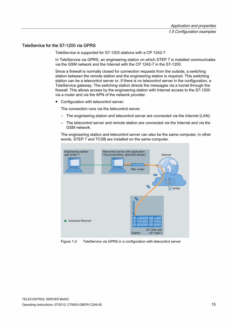
TeleService for the S7-1200 via GPRS TeleService is supported for S7-1200 stations with a CP 1242-7.
In TeleService via GPRS, an engineering station on which STEP 7 is installed communicates via the GSM network and the Internet with the CP 1242-7 in the S7-1200.
Since a firewall is normally closed for connection requests from the outside, a switching station between the remote station and the engineering station is required. This switching station can be a telecontrol server or, if there is no telecontrol server in the configuration, a TeleService gateway. The switching station directs the messages via a tunnel through the firewall. This allows access by the engineering station with Internet access to the S7-1200 via a router and via the APN of the network provider.
● Configuration with telecontrol server:
The connection runs via the telecontrol server.
– The engineering station and telecontrol server are connected via the Internet (LAN).
– The telecontrol server and remote station are connected via the Internet and via the GSM network.
The engineering station and telecontrol server can also be the same computer; in other words, STEP 7 and TCSB are installed on the same computer.
Figure 1-2 TeleService via GPRS in a configuration with telecontrol server

Application and properties 1.5 Configuration examples
TELECONTROL SERVER BASIC 16 Operating Instructions, 07/2013, C79000-G8976-C249-05
● Configuration with TeleService gateway:
The connection runs via the TeleService gateway.
The connection between the engineering station and the TeleService gateway can be local via a LAN or via the Internet.
Figure 1-3 TeleService via GPRS in a configuration with TeleService gateway

TELECONTROL SERVER BASIC Operating Instructions, 07/2013, C79000-G8976-C249-05 17
Installation and commissioning 22.1 Required devices, software, licenses and information
The devices, operating systems, software, licenses and information described below are required to operate TELECONTROL SERVER BASIC.
Required devices ● To operate TCSB, you require a computer (PC) with the following modules:
– DVD drive
– Network adapter for connecting to the Internet or to the GSM network
– Required work memory: 4 GB work memory
This applies to the telecontrol server (computer with complete software)
● For the TeleService functions (engineering station) for S7-1200 stations with a CP 1242-7, you require a computer. This can be the computer of the telecontrol server or the computer of the TeleService gateway.
Compatible operating systems the application can run on a PC with one of the following operating systems:
● Microsoft Windows 7 Professional 32/64-bit + Service Pack 1
● Microsoft Windows 7 Enterprise 32/64-bit + Service Pack 1
● Microsoft Windows 7 Ultimate 32/64-bit + Service Pack 1
● Microsoft Windows Server 2008 32-bit + Service Pack 2
● Microsoft Windows Server 2008 R2 64-bit + Service Pack 1
Required software ● The TELECONTROL SERVER BASIC software
● On the engineering station from which you want to execute TeleService functions to S7-1200 stations with a CP 1242-7, STEP 7 as of version V11 is required.
Required licenses, contracts and connections ● A valid license for TELECONTROL SERVER BASIC.
● For the TeleService functions for S7-1200 stations with a CP 1242-7, a STEP 7 license is required on the engineering station.
No additional license is necessary for the TeleService function.

Installation and commissioning 2.1 Required devices, software, licenses and information
TELECONTROL SERVER BASIC 18 Operating Instructions, 07/2013, C79000-G8976-C249-05
● For the remote stations, you require contracts with GSM network providers. The contracts must include SIM cards for the CP 1242-7 and allow access to the Internet.
Generally, standard contracts are adequate.
● An SMS gateway for converting the wake-up e-mail of the telecontrol server into an SMS message
● An SMTP server (public or private) for sending e-mails
● Internet access
IP address for Internet access For the Internet access of the telecontrol server, you require an IP address or a name that can be resolved by DNS. The IP address can be dynamic but a fixed IP address is better.
Note
In a large systems in particular, the use of a name that can be resolved using DNS is advisable when configuring the Internet access for CP 1242-7 modules in case you want to change the network provider.
Reachability of the telecontrol server The telecontrol server must be permanently reachable from the GSM network. To allow this, the computer must be connected directly to the GSM network via a dedicated line or, for example to the Internet via DSL.
Note Where possible, avoid telecontrol server downtimes.
If the telecontrol server cannot be reached, the stations (MD720-3; CP 1242-7 with the "permanent" setting) repeatedly attempt to establish the connection to the telecontrol server. This creates data volumes that can mean costs.
Required information To commission the telecontrol server and the telecontrol stations connected to it, the following information is required:
● Information about the Internet access of the telecontrol server
– Port configuration of the router for the Internet access
– Internet IP address of the telecontrol server
or
Name of the telecontrol server that can be resolved by DNS (if DNS is used)
– Port number of the telecontrol server for port forwarding via the router
● Information about the SMTP server and SMS gateway to be able to send wake-up SMS messages from the telecontrol server.
Installation and commissioning 2.2 Installation of the TCSB software
TELECONTROL SERVER BASIC Operating Instructions, 07/2013, C79000-G8976-C249-05 19
● Information about the Configuration and Monitoring Tool of TCSB
– Default user name for the administrator (administrator)
– Default password of the administrator (0000)
You will find this information in the section Starting the CMT (Page 52) in this manual.
● Information about connection establishment with the remote station
– APN (Access Point Name)
– User name for APN
– Password for APN
– DNS 1
– DNS 2
This information is configured in the STEP 7 project of the CP 1242-7.
● Information for TeleService functions (S7-1200 + CP 1242-7)
– TeleService user name (as configured for the CP)
Entry on the engineering station
– TeleService password (as configured for the CP)
Entry on the engineering station
– Server password
The server password is configured in TCSB. It is optional and project-specific. If no server password is configured, a default internal system password is used automatically.
Required for access by the engineering station to the telecontrol server
Entry on the engineering station
– IP address of the telecontrol server
Entry on the engineering station
2.2 Installation of the TCSB software
Requirement for installation You require administrator privileges on the computers on which you want to install the TCSB software.
To install the software, you require the following components of the product package:
● The software CD containing the TELECONTROL SERVER BASIC software.
● USB stick containing the license key for installing TCSB.
– You only require the license key for the TCS Basic installation option.
– You do not require a license key for the Client PC installation option.

Installation and commissioning 2.2 Installation of the TCSB software
TELECONTROL SERVER BASIC 20 Operating Instructions, 07/2013, C79000-G8976-C249-05
Firewall settings (ports) Just as with any computer connected to the Internet or to another IP network, the telecontrol server should be protected at least by the firewall of the operating system and/or the connected router against attacks from the connected network.
Remember that during installation of the system, several ports need to be opened and other changes need to be made in your system. These settings are displayed during installation. You can print these settings during the installation or save them in a log file.
Note Response to a deactivated firewall
If the firewall is deactivated during installation, the necessary incoming and outgoing rules will not be created. In this case, no warning is output.
The installation wizard After starting the installation, the installation wizard opens and supports you during the installation.
Figure 2-1 Installation wizard, program selection

Installation and commissioning 2.2 Installation of the TCSB software
TELECONTROL SERVER BASIC Operating Instructions, 07/2013, C79000-G8976-C249-05 21
Installation options You can install the "TELECONTROL SERVER BASIC" software of one or on different computers. Here, you have the following options available in the installation wizard:
● "TCS Basic"
This option installs the complete "TELECONTROL SERVER BASIC" software.
The PC becomes the telecontrol server including the database, Telecontrol Manager and Configuration and Monitoring Tool (CMT).
● "Client PC"
Installation on the PC of an OPC client allows the OPC client to connect to the OPC server of the telecontrol server.
The "Configuration and Monitoring Tool" (CMT) is also installed which means that you can also configure the TCSB system on this PC.
● "Automation License Manager"
This option installs the Automation License Manager (ALM). The ALM is only required if you select the "TCS Basic" option; in other words, when you install the entire software.
Installation on a single computer The entire software is installed on this computer. Enable the following options in the installation wizard:
● "TCS Basic"
● "Automation License Manager"
Enable the option if there is currently no up-to-date Automation License Manager installed on the computer.
Installation on several computers ● The complete software is installed on one computer, the telecontrol server. The license
key is required for this computer.
Enable the following options in the installation wizard:
– "TCS Basic"
– "Automation License Manager"
Enable the option if there is currently no up-to-date Automation License Manager installed on the computer.

Installation and commissioning 2.3 Changing the port, network and DCOM settings
TELECONTROL SERVER BASIC 22 Operating Instructions, 07/2013, C79000-G8976-C249-05
● If you are installing on other computers, select the "Client PC" option.
With this installation variant, you prepare these computers as OPC clients from which you can access the OPC server of the telecontrol server.
The CMT is also installed on these computers. This means that you can configure the CMT on these computers or monitor the connections to the remote S7 stations from these PCs.
When setting up the users on the PCs for OPC server and OPC client, refer to the note in the section Settings (Page 93).
Installation Follow the steps below to install the program:
1. Insert the software CD in the CD-ROM drive of the computer.
2. In the file management, go to the CD-ROM drive directory.
3. Start the installation by double clicking on the "setup.exe" entry.
The installation wizard opens.
4. Select the options relevant for you from those described above.
The installation wizard guides you through the remaining steps in installation.
Remember that during installation of the system, several ports need to be opened and other changes need to be made in your system. See also section Changing the port, network and DCOM settings (Page 22).
Automated installation You will find information on the automated installation of multiple computers in the appendix Automated installation (Page 101).
2.3 Changing the port, network and DCOM settings
Network settings To ensure that the system operates correctly, the following settings must be made:
1. Open the following dialog on the server PC and the client PCs:
"Network and Internet" > "Network and Sharing Center" > "Advanced sharing settings"
2. Turn on "Network discovery" for both networks "Home or Work" and "Public".
Opening changed ports If you change port numbers, you will need to open the ports used in the router or using the functions of the operating system.
Below you will find the ports of TCSB along with their significance and the default numbers:

Installation and commissioning 2.4 Uninstalling
TELECONTROL SERVER BASIC Operating Instructions, 07/2013, C79000-G8976-C249-05 23
● MSC Listener port
Listener port for stations of the type S7-200 + MD720-3
The port must be opened for communication with remote stations of the type S7-200 with the MD720-3 modem. The port is not relevant for TeleService.
Default port number: 26862
● IP-T Listener port
Listener port for stations of the type S7-1200 + CP 1242-7
The port must be opened for communication with the engineering station and with remote stations of the type S7-1200 with CP 1242-7.
Default port number: 55097
● OPC server port
The port must be opened for communication with CMT client PCs.
CMT client PCs can be PCs of the OPC clients and other PCs with the CMT installed (installation option "Client PC").
Default port number: 26864
● Port of the database server
Port of the database server for TCP connections with CMT client PCs
Default port number: 26865
You can change the default port numbers in the CMT, refer to section Settings (Page 93) > "System configuration".
Settings for OPC The necessary DCOM settings are made and access rights for OPC communication are assigned during installation of TCSB. You will find details in the file that you can open and save during installation.
You will find further information on setting up OPC communication on a Windows computer in /6/ (Page 108).
Note
If the telecontrol server cannot be reached, the stations (MD720-3; CP 1242-7 with the "permanent" setting) repeatedly attempt to establish the connection to the telecontrol server. This creates data volumes that can mean costs.
2.4 Uninstalling
Uninstalling the software You can uninstall TELECONTROL SERVER BASIC with the usual Windows tools:
"Control Panel" > "Programs" > uninstall program

Installation and commissioning 2.4 Uninstalling
TELECONTROL SERVER BASIC 24 Operating Instructions, 07/2013, C79000-G8976-C249-05
TELECONTROL SERVER BASIC Operating Instructions, 07/2013, C79000-G8976-C249-05 25
The OPC server 33.1 The OPC server of TCSB
The OPC server of TELECONTROL SERVER BASIC The OPC server of TCSB provides any OPC-DA client with access to certain values in the connected controllers and to status information of the individual GPRS connections to the connected controllers.
The OPC server of TCSB is an out-process server that can be configured locally or remotely. Data access is via a COM server. Die OPC specification is OPC Data Access.
The following methods are supported:
● Synchronous and asynchronous reading of data
● Asynchronous writing of data
● Transfer of events (OPC events)
Up to four OPC clients with access to a total of 1 000 000 OPC items can be connected at the same time.
The OPC server supports hierarchical address browsing.
Name of the OPC server The OPC server of TCSB has the following name:
OPC.SimaticNET.TCSB
This server name must be configured on the connected OPC client.
Supported S7 systems Data of the following remote SIMATIC S7 systems can be transferred to an OPC client as OPC items via the OPC server of TCSB:
● SIMATIC S7-200 with SINAUT MD720-3 modem
● SIMATIC S7-1200 with CP 1242-7
The OPC server 3.2 Process OPC items
TELECONTROL SERVER BASIC 26 Operating Instructions, 07/2013, C79000-G8976-C249-05
Data of the connected stations The following classes of OPC items are transferred from the connected S7 stations:
● Process OPC items
Variables can be stored in data blocks on the controller. These variables can be transferred by user-defined OPC items.
The variables are configured in the user program of the CPU.
The mapping of the data areas of the CPU to OPC items is configured using the OPC client.
● System OPC items
These are OPC items that are transferred by every connected station. Essentially these are status values and statistical information about the particular station or connection. Requesting data establishes a connection with a station that is not currently connected.
These system items do not need to be configured on the OPC client.
● Multicast OPC items
Multicast OPC items are system items with write access for entire projects; in other words, for groups of stations.
● Status OPC items
These are items supplied by the server itself.
3.2 Process OPC items
Process OPC items All process OPC items transfer data from the process image of the CPU. They can be created user-defined and all have read and write access.
For stations with a CP 1242-7, separate the CPU data areas for writing and reading items. Items should have either read or write access.
Note Writing and reading OPC items with separate CPU data areas (CP 1242-7)
If you both write and read with an item, it is possible that the value stored on the OPC server will differ from the value in the process image following a write job.
For stations with a CP 1242-7, use OPC items either for write or for read access. Writing and reading items must access different CPU data areas. Reason:
For read and write communication with the CPU, the CP 1242-7 has two process images (reading and writing) and uses two different program blocks with different data blocks that access the process data of the CPU. Fo rmore information, refer to section Data management in the process images of the CP 1242-7 (V1.x) (Page 47).

The OPC server 3.2 Process OPC items
TELECONTROL SERVER BASIC Operating Instructions, 07/2013, C79000-G8976-C249-05 27
Reading process OPC items the first time When the OPC client is started, the "Refresh Values" bit must be set to 1 so that the current values of the remote station can be read in.
Syntax <protocol>:[<projectname>.<stationname>.<slot>]<DB-no.>,
<type><address>{.<length>}
{,<quantity>}
Meaning of the parts of the name ● <protocol>
System ID as follows:
– TCS
System ID of TCSB (in all item names)
– MSC
The "MSC" ID of SINAUT MICRO SC is also supported.
For the syntax, refer to the manual of SINAUT MICRO SC, see References in the appendix of the manual /4/ (Page 108).
● <projectname>
The project name of the connection configured in CMT
● <stationname>
The station name of the connection configured in CMT
● <slot>
Slot of the relevant module:
– For the CP 1242-7, the connection is specified via slot 101, 102 or 103 of the CP.
– For the MD720-3, the slot is always = 0.
● <DB-no.>
Number of the data block in the user program of the CPU that contains the relevant process data.
Only access to DB1 is supported.
● <type>
Data types supported by the telecontrol server (see table below)
● <address>
Start index (byte offset) of the variable

The OPC server 3.2 Process OPC items
TELECONTROL SERVER BASIC 28 Operating Instructions, 07/2013, C79000-G8976-C249-05
● <length>
Length of a string in bytes. Only necessary when using a string as the data type.
● <quantity>
Optional information only required when using arrays:
Number of array elements to be read starting at the start index specified in the "Address" parameter.
Data types of the supported variables Data type 1) Description OLE data type (in
TCSB) S7 data type
B Byte (unsigned) VT_UI1 BYTE W Word (unsigned) VT_UI2 WORD D Double word (unsigned) VT_UI4 DWORD CHAR Byte (signed) VT_I1 BYTE INT Word (signed) VT_I2 INT DINT Double word (signed) VT_I4 DINT REAL Floating point number VT_R4 REAL STRING 2) String with string length VT_BSTR 2) STRING
DTL (S7-1200) DT Date and time of day 3) VT_DATE 4) DT (S7-200)
1) Data type of the variables that TCSB provides for the browser of an OPC client. 2) The OPC data type "String" must not be used on connections with S7-200 stations. 3) The times of day used by TCSB are described in the section Times of day in the system (Page 49). 4) The accuracy of the time-of-day is supported by TCSB only down to milliseconds.
Examples of the declaration of items ● TCS:[project1.station1.101]DB1,W32
Telecontrol server item from connection to project 1, station 1, slot 101, data block 1, data type "word", start index 32
● TCS:[project1.station1.102]DB1,STRING40.12
Telecontrol server item from connection to project 1, station 1, slot 102, data block 1, data type "string", start index 40, length 12 bytes

The OPC server 3.3 System OPC items
TELECONTROL SERVER BASIC Operating Instructions, 07/2013, C79000-G8976-C249-05 29
3.3 System OPC items
System OPC item information System OPC items return status and statistical information from S7 stations or from individual TeleService connections.
Syntax of the system OPC items ● Syntax of the system OPC items of S7 stations:
<protocol>:[<stationname>]<itemname>
● Syntax of the system OPC items of TeleService connections:
<protocol>:[<projectname>.TS Access Point.<n>]<itemname>
Meaning of the parts of the name ● <protocol>
System ID as follows:
– TCS
System ID of TCSB (in all item names)
– MSC
The "MSC" ID of SINAUT MICRO SC is also supported.
For the syntax, refer to the manual of SINAUT MICRO SC, see References in the appendix of the manual /4/ (Page 108).
● <stationname>
The station name of the connection configured in CMT
● <projectname>
The project name configured in CMT
● TS Access Point.<n>
TS Access Point = Fixed identifier of the system items of TeleService connections
<n> = number of the TeleService connection (1 ... 5)
● <itemname>
Name of the particular system item
The names of the system items and their support by the various station types can be found in the following table.

The OPC server 3.3 System OPC items
TELECONTROL SERVER BASIC 30 Operating Instructions, 07/2013, C79000-G8976-C249-05
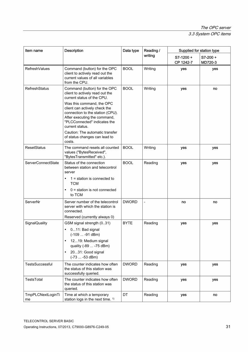
Item name of the system OPC items The following system variables of TCSB are made available as system OPC items for the various station types:
Supplied for station type Item name Description Data type Reading /
writing S7-1200 + CP 1242-7
S7-200 + MD720-3
BytesReceived Counter for received bytes (counted value from station)
DWORD Reading yes yes
BytesTotal Counter for the total number of transferred bytes (counted value from the station; the counter cannot be reset).
DWORD Reading yes yes
BytesTransmitted Counter for sent bytes (counted value from station)
DWORD Reading yes yes
CellID ID of the wireless cell in the area of the station
DWORD Reading yes yes
DeviceID Device name of the GPRS modem or order number of the CP
STRING Reading yes yes
FirmwareVers Firmware version of the GPRS modem
STRING Reading yes yes
GPRS connection to station For stations with CP 1242-7: 0 = not connected 1 = connected 2 = temporary station logged
off (LOG OFF) 3 = permanent station not
reachable
DWORD GPRSConnected
GPRS connection to station For stations with MD720-3: 1 = connected 0 = not connected
BOOL
Reading yes yes
PLCConnected Communication with the station (CPU): 1 = communication error-free 0 = communication disrupted
BOOL Reading yes yes
PLCCpuState Status of CPU (RUN, STOP) DWORD Reading yes yes Protocol Transmission protocol (station
type) 1 = S7-1200 + CP 1242-7 0 = S7-200 + MD720-3
DWORD Reading yes yes
The OPC server 3.3 System OPC items
TELECONTROL SERVER BASIC Operating Instructions, 07/2013, C79000-G8976-C249-05 31
Supplied for station type Item name Description Data type Reading / writing S7-1200 +
CP 1242-7 S7-200 + MD720-3
RefreshValues Command (button) for the OPC client to actively read out the current values of all variables from the CPU.
BOOL Writing yes yes
RefreshStatus Command (button) for the OPC client to actively read out the current status of the CPU. Was this command, the OPC client can actively check the connection to the station (CPU). After executing the command, "PLCConnected" indicates the current status. Caution: The automatic transfer of status changes can lead to costs.
BOOL Writing yes no
ResetStatus The command resets all counted values ("BytesReceived", "BytesTransmitted" etc.).
BOOL Writing yes yes
ServerConnectState Status of the connection between station and telecontrol server 1 = station is connected to
TCM 0 = station is not connected
to TCM
BOOL Reading yes yes
ServerNr Server number of the telecontrol server with which the station is connected. Reserved (currently always 0)
DWORD - no no
SignalQuality GSM signal strength (0..31) 0...11: Bad signal
(-109 ... -91 dBm) 12...19: Medium signal
quality (-89 ... -75 dBm) 20...31: Good signal
(-73 ... -53 dBm)
BYTE Reading yes yes
TestsSuccessful The counter indicates how often the status of this station was successfully queried.
DWORD Reading yes yes
TestsTotal The counter indicates how often the status of this station was queried.
DWORD Reading yes yes
TmpPLCNextLoginTime
Time at which a temporary station logs in the next time. 1)
DT Reading yes no

The OPC server 3.4 Multicast OPC items
TELECONTROL SERVER BASIC 32 Operating Instructions, 07/2013, C79000-G8976-C249-05
Supplied for station type Item name Description Data type Reading / writing S7-1200 +
CP 1242-7 S7-200 + MD720-3
WakeUp With this command, a temporary station is requested to establish a connection to the telecontrol server. 1 = establish GPRS
connection (wake-up SMS) 0 = terminate GPRS
connection
BOOL Writing yes no
WakeUpTimeout Configured monitoring time during which the station should have connected following a wake-up SMS message (see "Station monitoring"). For a permanent station, this value is 0.
DWORD Reading yes no
1) TmpPLCNextLogginTime specified in the local time of the telecontrol server
Examples of the declaration of items ● TCS:[project1]CellID
System item "CellID" of an S7 station with CP 1242-7
● MSC:[project1]DeviceID
System item "DeviceID" of an S7 station with MD720-3 modem
● TCS:[project1.TS Access Point.4]BytesTotal
System item "BytesTotal" of the fourth TeleService connection of a project
3.4 Multicast OPC items
Multicast items Multicast OPC items are system items with write access for an entire TCSB project. The following multicast items are available:
● RefreshValues
● RefreshStatus
● WakeUp
● ResetStatus

The OPC server 3.5 Status OPC items
TELECONTROL SERVER BASIC Operating Instructions, 07/2013, C79000-G8976-C249-05 33
Syntax of the multicast items <protocol>:[<projectname>.<itemname>]
Meaning of the parts of the name ● <protocol>
System ID as follows:
– TCS
System ID of TCSB (in all item names)
– MSC
The "MSC" ID of SINAUT MICRO SC is also supported.
For the syntax, refer to the manual of SINAUT MICRO SC, see References in the appendix of the manual /4/ (Page 108).
● <projectname>
Name of the project configured in CMT
● <itemname>
Name of the particular system item
You will find the description of the system items in the section System OPC items (Page 29).
3.5 Status OPC items
Status items The OPC server itself always returns the two following status items:
● OPCServerDown
This item with the data type BOOL provides information about the reachability of the OPC server by the telecontrol manager of TCSB:
– 1 = OPC server not reachable
– 0 = OPC server reachable
● DatabaseDown
This item with the data type BOOL provides information about the reachability of the database by the telecontrol manager of TCSB:
– 1 = database not reachable
– 0 = database reachable

The OPC server 3.6 Name space of the OPC server
TELECONTROL SERVER BASIC 34 Operating Instructions, 07/2013, C79000-G8976-C249-05
3.6 Name space of the OPC server
The name space of TCSB The name space of the OPC server of TCSB can be displayed by connected OPC clients and searched using browsing.
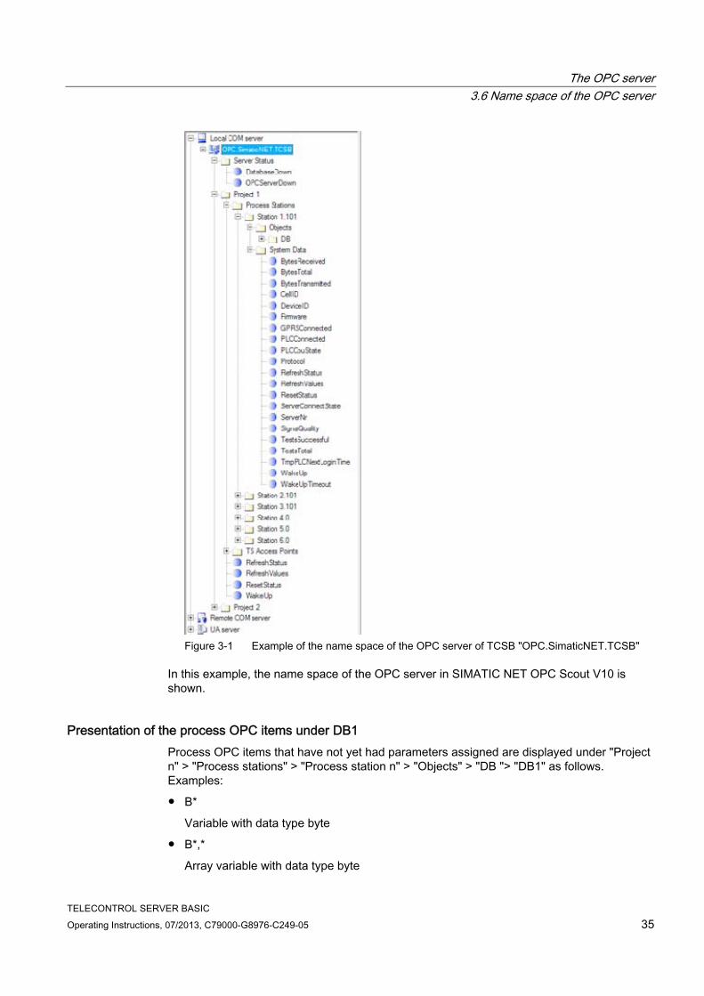
The OPC server of TCSB is displayed with the name "OPC.SimaticNET.TCSB". Its data and information are structured hierarchically:
● Server status (status items of the OPC server)
– Status item "OPCServerDown"
– Status item "DatabaseDown"
● Project 1
– Process stations
Station 1
Objects (contains DB1 under "DB")
System Data (contains the system items)
Station 2
Station n
– TS access points
Contains system items for 5 TeleService connections per project.
– Multicast item "WakeUp"
– Multicast item "RefreshStatus"
– Multicast item "RefreshValues"
– Multicast item "ResetStatus"
● Project 2
● Project n
The OPC server 3.6 Name space of the OPC server
TELECONTROL SERVER BASIC Operating Instructions, 07/2013, C79000-G8976-C249-05 35
Figure 3-1 Example of the name space of the OPC server of TCSB "OPC.SimaticNET.TCSB"
In this example, the name space of the OPC server in SIMATIC NET OPC Scout V10 is shown.
Presentation of the process OPC items under DB1 Process OPC items that have not yet had parameters assigned are displayed under "Project n" > "Process stations" > "Process station n" > "Objects" > "DB "> "DB1" as follows. Examples:
● B*
Variable with data type byte
● B*,*
Array variable with data type byte

The OPC server 3.6 Name space of the OPC server
TELECONTROL SERVER BASIC 36 Operating Instructions, 07/2013, C79000-G8976-C249-05
● CHAR*
Variable with data type character
● CHAR*,*
Array variable with data type character
● STRING*.*
Variable with data type string
● STRING*.*,*
Array variable with data type string
The asterisks (*) are placeholders for address, length and quantity (array). Examples:
● "String"
– STRING*.*,* (item without parameter assignment)
– STRING5.7,2 (item with parameter assignment)
Parameter assignment of address = 5, length = 7 and quantity = 2
● "Character"
– CHAR*,* (item without parameter assignment)
– CHAR5,2 (item with parameter assignment)
Parameter assignment of address = 5, and quantity = 2

TELECONTROL SERVER BASIC Operating Instructions, 07/2013, C79000-G8976-C249-05 37
Notes on configuration and operation 44.1 Overview of configuration
Configuration of the remote stations The remote S7 stations are configured in SIMATIC STEP 7. For the various station types (S7-200, S7-1200), make sure that you have the required version of STEP 7.
You will find more detailed information on the MD720-3, the CP 1242-7 or the OPC routing software SINAUT MICRO SC in the relevant manual (see References in the appendix of the manual).
Configuration of TELECONTROL SERVER BASIC TCSB is configured with the CMT tool, see section The Configuration and Monitoring Tool (Page 51).
Here, all the basic settings of the system, the users and their rights and the connections to the remote stations are configured.
Transfer of configuration data to the runtime system When the configuration of the TCSB system or parts of the system is completed, the data can be transferred to the runtime system. Here, the following mechanisms come into effect:
● Transfer of the configuration data directly from the CMT
(Selection of a project > selection of the menu entry "File" > "Activate".)
● Transfer per project
The configuration data is always transferred to the runtime system for an entire project, not for individual stations or for multiple projects.
● Online transfer
After transferring the configuration data to the runtime system, productive operation starts immediately.
Even after transferring changed data, the system does not need to be restarted.
Changing configuration data during operation Configuration data can be changed during operation without having any direct influence on productive operation.
To avoid configuration errors, the modified configuration data can be compared with the productive data in the runtime system.
Do not transfer the modified data to the runtime system until you are sure that all the modified data is correct.
Notes on configuration and operation 4.2 Working with projects
TELECONTROL SERVER BASIC 38 Operating Instructions, 07/2013, C79000-G8976-C249-05
4.2 Working with projects
The project is an organizational unit In TCSB, management of all connections to the remote stations is structured in projects. In terms of the following properties, projects form an organizational unit:
● Access rights for project editors
Within a project, the names of all users are displayed for each user regardless of the user's rights.
Only one user can change data within a project at any one time.
● Transfer of data to the runtime system
When project data is activated, the data of the entire project is always transferred to the runtime system.
● Project import from a "SINAUT MICRO SC" application
Imported data from SINAUT MICRO SC is imported into a single project in TCSB.
The "Projects" entry therefore comes first in the system navigation of the CMT. This is the highest organizational level of the TCSB system.
Note Station number of stations with MD720-3
For stations connected via an MD720-3, the station number of the individual stations throughout all projects must be unique and different.
Importing projects from "SINAUT MICRO SC" TCSB provides the option of importing data from the "SINAUT MICRO SC" application. Prior to importing, the data does not need to be edited in SINAUT MICRO SC.
Following import, the stations of the previous MICRO SC project can be managed immediately by TELECONTROL SERVER BASIC.
Multiproject and multi-user capability The architecture of the TCSB system structured in independent projects means that, in particular in systems with a large number of stations, the configuration can be created at the same time in various projects and that the configuration can be performed by different editors in the various projects.

Notes on configuration and operation 4.3 The user concept
TELECONTROL SERVER BASIC Operating Instructions, 07/2013, C79000-G8976-C249-05 39
4.3 The user concept
Graduated user concept Both for configuration, management and operation of small but also extremely large systems, a graduated user concept was introduced with rights assigned as suitable for the various tasks:
● Administrators
One or more administrators can install and set up the system. They create the projects, set up the SMS gateway providers and the inter-station communication. Administrators have all rights and set up the users.
● Users
Within individual projects, the administrators assign different access rights to the users:
– Read
– Wake up
– Change
– Full access
You will find the individual functions assigned to these access rights in the section Access permissions (Page 86).
4.4 Inter-station communication
Inter-station communication within projects Inter-station communication between remote stations is possible only if the sending and destination station have the same communications components (MD720-3 or CP 1242-7). Inter-station communication between two stations with different communications components is not possible.
Inter-station communication between two stations is always via the telecontrol server that serves as an intermediary.
Inter-station communication between individual stations within a single project is generally possible.
Inter-station communication between stations in different projects must be enabled by an administrator to prevent the possibility of stations in different areas of responsibility communicating with each other. Inter-station communication between different projects is enabled in the CMT, see "Inter-station communication" in system navigation.
Notes on configuration and operation 4.5 Program blocks for the CPU
TELECONTROL SERVER BASIC 40 Operating Instructions, 07/2013, C79000-G8976-C249-05
4.5 Program blocks for the CPU
Communication between CPU and modem/CP For communication between the CPU and MD720-3 or CP 1242-7, program blocks are required for the CPU. The program block allow the connection establishment and termination, the sending and receiving of data and other communications tasks.
You will find a description of the blocks / instructions in the manuals of the MD720-3 and the CP 1242-7 (see References in the appendix of the manual). You will also find information on the telecontrol instructions for the CP 1242-7 in the STEP 7 V11 online help.
4.6 TeleService functions
TeleService with S7-1200 + CP 1242-7 The TeleService functions for the station type S7-1200 + CP 1242-7 are described in the manual of the CP 1242-7 (refer to the references) and in the online help of STEP 7.
TCSB automatically provides 5 access points per project for TeleService. This means that up to 5 TeleService users can access the stations of a project at the same time.
The CMT displays whether or not the TeleService access points are in use.
4.7 Increasing the availability of the system
Options for increasing the availability of the telecontrol system To increase the availability of process data for control centers or OPC clients, TCSB can be set up as a main and substitute server.
If you want to increase the availability of the communication paths, further CP 1242-7 modules can be inserted in S7-1200 stations. Different GSM network providers can also be configured.
4.8 Main and substitute telecontrol server
Telecontrol server: Main and substitute server If TCSB is installed as the main and substitute server, two parallel systems are installed by TCSB and these are independent of each other. Both systems have their own database and the complete communications functions of TCSB. The two TCSB systems do not monitor each other.

Notes on configuration and operation 4.8 Main and substitute telecontrol server
TELECONTROL SERVER BASIC Operating Instructions, 07/2013, C79000-G8976-C249-05 41
Configuration of the main and substitute server Make sure that the configuration data on the two systems are consistent with each other. You can achieve this by entering all the configuration data twice manually or after configuring the main system, by copying the database of the main system to the substitute system using operating system tools. Follow the steps outlined below:
1. Copy the database file from the following directory of the main system:
Programdata > Siemens > Automation > TCS Basic > Data > "Smsc.sqlite"
2. Insert the database file at the same location in the file system of the substitute system.
The existing "Smsc.sqlite" file on the substitute system is overwritten.
3. If necessary, adapt the addressing of the database server in the configuration of the substitute server under "Settings" if CMT and the database in the main system are installed on different computers.
Copying ensures the consistency of the configuration data. Since the system parameters of the main and substitute system can be configured in the CMT, following copying no editing of the system parameters of the substitute system is necessary.
Interaction between the main and substitute server In a normal situation, the stations are connected to the main telecontrol server. If the main server cannot be reached, the connection of the remote S7-1200 with the CP 1242-7 fails over from the main to the substitute server.
Switchover between the main and substitute server by the CP 1242-7 When establishing the GPRS connection to the telecontrol server, the CP automatically switches over to the substitute server after the 4th dialing attempt if the main server cannot be reached.
If the substitute server cannot be reached either, the 4th time the CP once again tries to connect to the main server.
The intervals of the redial attempts are controlled by the "Redial delay" parameter.
You will find an example in the section Redial delay of the CP 1242-7 (STEP 7) (Page 44).
Log files Since the main and substitute system have different dynamic characteristics relating to their runtime response, the log files have different contents in the database. When you copy the database, the log files are also copied.

Notes on configuration and operation 4.9 Connection establishment
TELECONTROL SERVER BASIC 42 Operating Instructions, 07/2013, C79000-G8976-C249-05
4.9 Connection establishment
Connection establishment A connection is always established by the MD720-3 modem or the CP 1242-7. During connection establishment, among other things passwords for authorization are exchanged.
Process data is sent as soon as the communications blocks or telecontrol instructions are called on the CPU.
Connection modes ● MD720-3
The MD720-3 does not have any different connection modes.
For all S7 stations with an MD720-3, the connection configuration is specified in the program blocks of the "SinautMicroSC" or "SinautMicroSC smart" library on the CPU. If these blocks are configured and called on the CPU, the modem immediately connects to the configured telecontrol server.
After the station has started up and the connection has been established the first time, there is a permanent TCP connection to the telecontrol server.
● CP 1242-7
The CP can be configured for the following connection modes.
– "Permanent" connection mode
When it starts up, the telecontrol server waits for the connection establishment by the stations. Following connection establishment, there is a permanent TCP connection to the telecontrol server even if data is not transferred permanently. If there is an interruption on the connection, the establishment of the connection can be triggered by a wake-up SMS (see below).
– "Temporary" connection mode
A connection is only established to the telecontrol server when required.
If a connection established by the CP is interrupted, the CP automatically attempts to re-establish the connection.
Triggering connection establishment for temporary stations (CP 1242-7) With "temporary" stations, connection establishment can be triggered by the following events:
● Event on the local CPU that is evaluated by the program.
In terms of the program, two situations need to be distinguished:
– Events that lead to a single connection establishment (for example alarms or commands from the operator).
– Expiry of an interval that leads to cyclic connection establishment (for example once daily for data transmission)
Notes on configuration and operation 4.10 Wake-up SMS for the CP 1242-7
TELECONTROL SERVER BASIC Operating Instructions, 07/2013, C79000-G8976-C249-05 43
● Request by a communications partner (OPC client or S7 station)
This leads automatically to the sending of a wake-up SMS message that triggers connection establishment.
● Request for TeleService by an engineering station
The request switched by the telecontrol server or TeleService gateway does not need to be evaluated in the program by the CPU.
● Wake-up SMS of the telecontrol server
The wake-up SMS can be triggered spontaneously on the telecontrol server. It is also possible to configure cyclic sending on the telecontrol server.
● Telephone wake-up call
The wake-up call can be sent from a telephone that has a phone number authorized in the STEP 7 project. The telephone must support the CLIP function (transfer of its own call number).
The connection establishment with the (main) telecontrol server is triggered.
● Telephone wake-up SMS
The wake-up SMS can be sent from a telephone that has a phone number authorized in the STEP 7 project. The telephone must support the CLIP function (transfer of its own call number) and the sending of SMS messages.
The connection establishment with the telecontrol server specified in the SMS is triggered.
Note Connection interrupted by GSM network provider
When using the GPRS service, remember that existing connections can be interrupted by GSM network providers for maintenance purposes.
4.10 Wake-up SMS for the CP 1242-7
Wake-up SMS Waking the station by a telecontrol server or by a TeleService gateway (TeleService) is achieved by sending an e-mail. The e-mail is sent to an SMS gateway via an SMTP server. The SMS gateway converts the e-mail into an SMS message and transfers this to the station.
The SMS gateway is configured on the telecontrol server (CMT) or TeleService gateway, see section Settings (Page 93).
If the wake-up SMS message is sent from a phone, the number of the phone must be authorized in the STEP 7 configuration of the receiving CP. The telephone must support the CLIP function (transfer of its own call number) and the sending of SMS messages.
Depending on the connection type and the triggering server or intermediary TeleService gateway, the following text must be transferred in the wake-up SMS:

Notes on configuration and operation 4.11 Redial delay of the CP 1242-7 (STEP 7)
TELECONTROL SERVER BASIC 44 Operating Instructions, 07/2013, C79000-G8976-C249-05
● For telecontrol connections:
– Text for the wake-up SMS message for establishing a connection to the telecontrol server:
TELECONTROL
– Text for the wake-up SMS message for establishing a connection to the main telecontrol server:
TELECONTROL MAIN
– Text for the wake-up SMS message for establishing a connection to the substitute telecontrol server:
TELECONTROL BACKUP
The configuration of the telecontrol server for the GPRS CP is set in STEP 7 in "Telecontrol interface > Operating mode > main or substitute telecontrol server".
Note Wake-up with a mobile phone One of the texts listed above can be used in a wake-up SMS message. With a wake-up call, the station always connects to the main telecontrol server.
● For TeleService connections:
– Text for the wake-up SMS message for establishing a connection to the first configured TeleService server:
TELESERVICE
or
TELESERVICE 1
– Text for the wake-up SMS message for establishing a connection to the second configured TeleService server:
TELESERVICE 2
The configuration of the TeleService server for the GPRS CP is set in STEP 7 in "Telecontrol interface > TeleService authorization > 1st or 2nd TeleService server".
4.11 Redial delay of the CP 1242-7 (STEP 7)
"Redial delay " parameter ("Telecontrol" mode) In "Telecontrol" mode, the redial delay is the waiting time between the connection establishment attempts of the CP if the telecontrol server cannot be reached. It is configured in STEP 7, parameter group "Operating mode" of the CP.
A basic value is configured for the waiting time before the next connection establishment attempt. After every 3 redial attempts, the basic value is doubled up to a maximum of 900 s. Range of values: 10 to 600 s.

Notes on configuration and operation 4.12 Monitoring times of connected OPC clients
TELECONTROL SERVER BASIC Operating Instructions, 07/2013, C79000-G8976-C249-05 45
Example: The basic value 20 results in the following intervals for connection establishment attempts:
● three times 20 s
● three times 40 s
● three times 80 s
● etc. up to max. 900 s
If a substitute telecontrol server is configured, the 4th time the CP attempts to connect to the substitute server, in this example therefore after the following time:
● three times 20 s redial delay +
● three times the connection monitoring time configured for the CP (time until the arrival of the TCP acknowledgement from the communications partner)
Note
Depending on your contract, costs may result from each connection establishment attempt.
4.12 Monitoring times of connected OPC clients
Adaptation of the monitoring times Frame delay times between remote stations and an OPC client cannot be predicted due to the network properties of the local area network (LAN) and the subsequent GSM network (WAN) as well as the unknown network load of the latter.
To avoid timeouts that can lead to additional frame traffic, it is advisable to set the monitoring times of the OPC client adequately high.
Read jobs of the OPC clients are completed by TCSB after 30 seconds with a timeout message if TCSB does not receive a reply from the remote station during this time.
4.13 Monitoring the connections (CP 1242-7)
Monitoring during operation (monitoring communications) During connection establishment, configured monitoring times for connection monitoring are exchanged with the telecontrol server.
If a connection is established, both partners check whether or not they can still reach each other.
After commissioning of the telecontrol server, the availability of the connections and the reachability of the stations can be monitored using two mechanisms:
● Connection monitoring
● Station monitoring

Notes on configuration and operation 4.13 Monitoring the connections (CP 1242-7)
TELECONTROL SERVER BASIC 46 Operating Instructions, 07/2013, C79000-G8976-C249-05
These two mechanisms function regardless of whether an OPC client is connected to the telecontrol server.
Connection monitoring The connection monitoring is based on keepalive frames sent cyclically by the station (modem/CP) to the telecontrol server.
The connection monitoring is only active on temporary connections during the phases of connection establishment.
● Keepalive timeout
When the keepalive time expires, the station (CP/modem) sends a keepalive frame. The length of the keepalive time is configured on the telecontrol server and the station (CP/modem) is informed of this during connection establishment.
● The tolerance time
The telecontrol server expects a data or keepalive frame within a configurable time, the tolerance time. If the telecontrol server has not received a frame from the station within the tolerance time, it assumes that the connection has aborted.
Note Configuring the tolerance time
Depending on the properties of the networks in between and the load on the system, the receipt of a keepalive frame may be delayed. For this reason, make sure you take this into account in the tolerance time. The tolerance time is set to 1 minute as default.
Station monitoring Station monitoring serves the following two purposes:
● Time-of-day synchronization
The telecontrol server transfers the time of day to the station as UTC.
In MICRO SC, time-of-day synchronization had to be configured using a separate parameter. This parameter no longer exists in TCSB.
● Monitoring of the station
The status is indicated by the status icon in the CMT.
Station monitoring monitors both the CP and the reachability of the CPU. The reachability of the CPU is transferred with the status data of the CP.
Even on permanent connections, it is possible that process data does not change over a longer period and therefore does not trigger any data traffic from the station.
Monitoring is cyclic in minutes. After the monitoring time has expired, TCSB queries the status data of the CP.
The interval of the monitoring time can be set in the "Station monitoring" parameter group for each station in the CMT. When the monitoring time has expired, the connection is assumed to have aborted.

Notes on configuration and operation 4.14 Data management in the process images
TELECONTROL SERVER BASIC Operating Instructions, 07/2013, C79000-G8976-C249-05 47
The consequences of this depend on the station type and the connection mode:
– Stations with MD720-3
No other consequences
– CP 1242-7
"Permanent" connection mode: The telecontrol server sends a wake-up SMS message to the station.
"Temporary" connection mode: The telecontrol server automatically sends a wake-up SMS message to the station. The station establishes a connection and sends the data from the process image when the wake-up SMS message was transferred successfully.
4.14 Data management in the process images
4.14.1 Data management for communication with S7-200 stations
Process images for TCSB and S7-200 CPU The values of OPC items are transferred unchanged form an OPC client via TCSB and the MD720 modem to the S7-200 CPU. Here, the modem is only an intermediary.
When all value changes of the station are transferred to the telecontrol server, the process image of TCSB and the process data in the data block of the CPU match. This applies both to the spontaneous sending of values and cyclic data exchange as well as reading from the device.
If the address information (specified offset) of a read job is higher than the process image, the entire read job is acknowledged negatively and no data is transferred.
4.14.2 Data management in the process images of the CP 1242-7 (V1.x)
Send and receive process image of the CP The process images on the CP are created for communication with the OPC server of the telecontrol server.
In contrast to the CPU or the telecontrol server, the CP 1242-7 (V1.x) manages the process data in two process images:
● Send process image (read direction of the control system)
After the startup or restart of a station, the TC_SEND program block sets up the send process image of the CP in the program of the CPU to be able to supply it with data. To achieve this, it may be necessary to call the block several times.

Notes on configuration and operation 4.14 Data management in the process images
TELECONTROL SERVER BASIC 48 Operating Instructions, 07/2013, C79000-G8976-C249-05
Data sent to the telecontrol server is read from the send process image. This affects:
– Spontaneous transfer of data
– Read jobs of an OPC client (via TCSB)
– Cyclic data exchange
● Receive process image (write direction of the control system)
Using a write job from TCSB, data is written to the receive process image of the CP.
The TC_RECV program block reads the data out of the receive process image and writes it to the programmed memory areas of the CPU.
Note the following points when reading and writing an OPC client:
● Different address ranges for reading and writing on the CP
The data transfer between the two process images of the CP and the process data of the CPU is handled by two blocks TC_SEND and TC_RECV.
● Different sizes of the send and receive process image
The size of the send process image and the receive process image on the CP may differ.
These system properties can lead to the following behavior:
System response when reading and writing ● No delivery of values read values
If the address area for write access (receive process image of the CP) is larger than the address area for read access (send process image of the CP), the CP acknowledges the entire read job negatively. TCSB does not receive any data.
● Different values when writing and reading
If an OPC client writes items to the station and then reads the same items (read from device), under certain circumstances, values will be read for these items that differ from those written earlier. Reason: Compared with the currently written receive process image, the send process image of the CP may contain different values.
Synchronization of the process images of the CP Synchronize the receive and send process image of the CP using the user program to ensure that you access current process data. To do this, transfer each written value from the receive process image with the same offset to the send process image:
1. Copy the data received by TC_RECV from the data block of TC_RECV to the data block of TC_SEND.
2. Transfer the data to send process image of the CP using TC_SEND.
This ensures the following:
● The send process image is at least as large as the receive process image.
● After a write job of the OPC client, when this is followed by a read request and during cyclic data exchange, the previously written values are read and transferred to TCSB.

Notes on configuration and operation 4.15 Times of day in the system
TELECONTROL SERVER BASIC Operating Instructions, 07/2013, C79000-G8976-C249-05 49
Recommendation for the structure of the process images 1. Place all process data intended for write or read access in the lower address range (small
offset).
2. Place the process data intended only for read access in the upper address range (larger offset).
This ensures that the part of the send process image of the CP for write access is small and that the send process image is always larger that the receive process image.
4.15 Times of day in the system
Times of day used in the system The telecontrol server uses the following times:
● Local time of the time zone in which the telecontrol server is located.
The local time it is set on the PC using the tools of the operating system. It may differ from UTC.
● UTC (Coordinated Universal Time)
The time of day is output by the telecontrol server on the following interfaces as UTC. This time is not the same as the local time set on the server.
– On the OPC interface
The time stamps of all OPC items are output as UTC.
Remember this for the time of day handling on the connected OPC clients.
For information on the only exception "TmpPLCNextLoginTime", see below.
– For the time-of-day synchronization of the remote stations
The CP 1242-7 of the remote stations synchronizes itself with the telecontrol server using the UTC time. All time stamps of the remote stations are output as UTC.
Exception "TmpPLCNextLoginTime" The system variable of the system OPC item "TmpPLCNextLoginTime" specifies the time at which a temporary station logs in the next time (S7-1200 + CP 1242-7 only). This value is calculated by the telecontrol server.
This time of day is specified as the local time of the telecontrol server and not as UTC.
4.16 Overview of the passwords
Overview of the passwords used Below, you will find an overview of the passwords used on the telecontrol Server / TeleService gateway.

Notes on configuration and operation 4.16 Overview of the passwords
TELECONTROL SERVER BASIC 50 Operating Instructions, 07/2013, C79000-G8976-C249-05
System No. Password
Password configuration Password entry
Function
① User password / administrator password
CMT of the telecontrol server/TeleService gateway
CMT of the telecontrol server / TeleService gateway (when starting)
Protection of the telecontrol server / TeleService gateway against unauthorized access
② Telecontrol password CP 1242-7 Station by station in the
CMT of the telecontrol server/TeleService gateway
- Authentication of the CP 1242-7 with the telecontrol server (protection of the telecontrol server)
③ TeleService password CP 1242-7 At the start of the TeleService session on the engineering station
Protection from access to the CP in TeleService
④ Server password (optional)
Project by project in the CMT of the telecontrol server/TeleService gateway
At the start of the TeleService session on the engineering station
Protection from access to the telecontrol server in TeleService
Other passwords required by the GSM network provider, SMPT server provider or SMS gateway provider are not listed here.
4444
1111
2222
2222
3322 3333
XX
Overview of the passwords used (numbered symbols)

TELECONTROL SERVER BASIC Operating Instructions, 07/2013, C79000-G8976-C249-05 51
The Configuration and Monitoring Tool 55.1 Overview of functions
The Configuration and Monitoring Tool (CMT) The Configuration and Monitoring Tool (CMT) is the program user interface of the "TELECONTROL SERVER BASIC" application. It has two functional areas:
● Configuring
This functional area is used for configuring the telecontrol server:
– Configuration of the basic settings of the system, the users and their rights
– Configuration of the connections to the stations of the distributed telecontrol system
● Functions at runtime
In the runtime system, the telecontrol server is connected to the telecontrol stations. The following functions are available:
– Monitoring of the connections to the remote stations
– Sending wake-up SMS messages to stations when connections are terminated
Configuring the telecontrol server Among other things, you can configure the following objects and functions:
● Basic settings of the system
– Settings of the system and address parameters of the hardware
– Language of the program user interface
– Logging functions
● Specifying users and their rights
– Access permissions
– Passwords
● Setting up projects
Large projects are clearly structured in the CMT using objects (logical groups).
● Connection to the stations
This includes, for example, address information, the online behavior of the station, the type of monitoring, cycle times etc.
● Enabling inter-station communication between stations of different projects

The Configuration and Monitoring Tool 5.2 Starting the CMT
TELECONTROL SERVER BASIC 52 Operating Instructions, 07/2013, C79000-G8976-C249-05
● Configuring the network providers
● Activating projects
With "Activate", the configured data is transferred to the runtime system.
5.2 Starting the CMT
Starting the CMT To start the CMT, select the following program:
Windows Start menu > "SIMATIC" > "TCS Basic" > "Config and Monitoring Tool"
Logging on After the program has started, the logon window of the CMT is displayed.
Figure 5-1 Logon window of the CMT (installation only of the CMT)
1. Enter a configured user name or leave the default user name.
2. Enter the corresponding password.
– If you have not installed a CMT client but log on with the telecontrol server, click the "Logon" button (see point 6).
– If you logon with a CMT client (installation option "Client PC"), check the following information in the "Database configuration" box.
The database server is located on telecontrol server.
3. Enter the IP address or a name for the database server that can be resolved by DNS.
4. Check of the number of the listener port of the database server and if necessary correct this.

The Configuration and Monitoring Tool 5.2 Starting the CMT
TELECONTROL SERVER BASIC Operating Instructions, 07/2013, C79000-G8976-C249-05 53
5. Check the "Connection monitoring time" (milliseconds) of the listener port of the database server.
If the connection monitoring time is exceeded, you cannot log on with the CMT.
6. Click the "Logon" button.
The window of the CMT opens.
You will find a description of the installation options "TCS BASIC" (complete software) or"Client PC" in the section Installation of the TCSB software (Page 19).
The factory-set port numbers of TCSB are listed in the section Changing the port, network and DCOM settings (Page 22).
Initial logon The following user data is set in the factory:
User data Default values set in the factory Remark User name administrator Password 0000 (four zeros)
Access protection of the system - changing passwords If you want to protect the system from unauthorized access, you should change the factory-set administrator password. This procedure is described in the section Setting up users and administrators (Page 83).
Changing of the passwords of users is described in the section User data (Page 88).
Entering the wrong user name or password If you enter a user name that is not configured, an error message is displayed regardless of the password entered. One or a variety of incorrect user names can be entered any number of times without the system being locked.
Note Incorrect entry of the password When entering the default user name:
If you enter an incorrect password with the default user name (see above) an error message is displayed. You can attempt to enter the factory-set password any number of times to log on with the system. If you enter an incorrect password, a lock out time begins that is extended with each attempt to logon with an incorrect password.
When entering a configured user name: If you enter an incorrect password along with a configured user name, an error message is displayed. If you enter an incorrect password, a lock out time begins that is extended with each attempt to logon with an incorrect password.

The Configuration and Monitoring Tool 5.3 The CMT window
TELECONTROL SERVER BASIC 54 Operating Instructions, 07/2013, C79000-G8976-C249-05
Note Loss of the administrator password
Note down a newly assigned or modified administrator password and keep this in a safe place.
If only one administrator is set up, the loss of the administrator password means that no more administrator tasks can be performed.
There is no way in which the system can be reset to the factory-set administrator password.
5.3 The CMT window
5.3.1 Layout of the window
Automatically created project at the first logon The first time you open the CMT, a project with project number "(1)" is created automatically in the navigation area below the highest entry "Projects".
With suitable access rights, you can update, rename or delete this project to suit your requirements. The procedure for this is described below.
Layout of the user interface The program user interface of the CMT is divided into the following areas:
Figure 5-2 Window layout of the CMT

The Configuration and Monitoring Tool 5.3 The CMT window
TELECONTROL SERVER BASIC Operating Instructions, 07/2013, C79000-G8976-C249-05 55
The subareas have the following functions:
No. Area / subarea Function
① Title bar Display of the name of the program
② Menu bar Contains the menus
③ Toolbar Contains icons for individual functions
④ System navigation Display of the structure of the configured telecontrol system and entries for the system settings *)
⑤ Object area The following content can be displayed: Parameters of the object selected in the navigation area. The
displayed parameters in the parameter area differ depending on the selected object (project, station, user etc.).
Display of the users and administrators Display of the settings of the system.
This view is shown after selecting the "Options" > "Settings" menu.
⑥ Command bar Contains buttons for functions for the object displayed in the object area:
⑦ Parameter area The following content can be displayed: *) Parameters of the object selected in the object area System variables of the connection selected in the object area
Detailed information about the system variables can be found in the section Diagnostics and statistical data (system variables) (Page 97).
⑧ Parameter navigation Display of the parameter groups of the object selected in the object area. The parameter navigation is available only for objects with a larger number of parameters.
⑨ Activated parameters This area shows the parameters transferred (activated) to the runtime system for the connection selected in the object area. If changes are made to the configuration, the area can be opened to check the changes by clicking on the arrow icon at the right hand edge of the window. By clicking on the arrow icon again the area is hidden.
*) The content displayed depends on the rights of the particular user.
Dependency of the displayed data on the access rights of the user If a user does not have all the rights required to operate the system, individual configurable boxes or buttons may be grayed out in the program user interface. Detailed information about user rights can be found in the section Access permissions (Page 86).
System navigation The system navigation shows the structure of the TCSB system and is used to select an object. The editing functions are available in the object area and in the parameter area.

The Configuration and Monitoring Tool 5.3 The CMT window
TELECONTROL SERVER BASIC 56 Operating Instructions, 07/2013, C79000-G8976-C249-05
The following entries are displayed in the system navigation:
● Projects
– Project with status icon and (project number)
● Users
● Inter-station communication
● SMS gateway provider
Object area - general contents The following contents are displayed if you select the relevant entry in the system navigation or select the menu command "Options" > "Settings".
● Users
Display of the properties of the created users
● Inter-station communication
Display of the projects available for inter-station communication
● GSM network provider
Display of the configured GSM network providers
● System settings
This view is shown after selecting the "Options" > "Settings" menu.
Here, an administrator can make the system settings of the CMT.
Object area - project-specific contents The following contents of the object area are displayed if you select the "Projects" entry or select one of the individual projects in system navigation.
● Status icon
The connection status for monitoring an object is indicated by the status icon.
● Detailed display of the subobjects of an object selected in the navigation area
Examples:
– The "Projects" entry is selected in the navigation area: The object area shows all projects of the system with additional information.
– A project is selected in the navigation area: The object area shows the individual stations of the project.
If a project is selected in the navigation area, the object area has three tabs:
– Connections
Shows details of the connections to the stations of the project.

The Configuration and Monitoring Tool 5.3 The CMT window
TELECONTROL SERVER BASIC Operating Instructions, 07/2013, C79000-G8976-C249-05 57
– TeleService access points to ES
This shows a maximum of 5 TeleService access points for the selected project with the IP address of the ES and the connection status.
– Rights
Here, the rights of the users are specified by the administrator for each project.
● Executing actions using the command bar
In some settings, the object area includes a command bar with which various actions can be executed.
Command bar The command bar provides buttons for various functions.
The buttons depend on the entry selected in the navigation or object area. The functions are explained in the description of the individual objects.
Parameter area The parameter area shows the parameters of the object selected in the object area. The individual parameters are described in the sections that follow.
The following applies generally:
● The parameter assignment of the objects depends on rights.
● The displayed parameters depend on the object selected in the object area.
● Configuration data can only be edited if you have the necessary rights.
● The parameters transferred to the runtime system are checked for plausibility.
● The parameter assignment must be consistent (for example the SMS number of a station must not be assigned more than once).
● If an input box is intended only for certain types of character, other types of character will be rejected.
Example: Letters cannot be entered in input boxes for phone numbers.
● Projects and connections with bad parameters are given the configuration status "invalid".
● Invalid parameters
If you enter parameters in input boxes and these are found to be invalid by the plausibility check they are indicated during input with a red frame (see figure).
Invalid parameters are not stored in the database. If you exit a dialog with invalid data, the invalid changed configuration data will be discarded.
Figure 5-3 Marking of input boxes with invalid parameters (red frame)

The Configuration and Monitoring Tool 5.3 The CMT window
TELECONTROL SERVER BASIC 58 Operating Instructions, 07/2013, C79000-G8976-C249-05
Parameter navigation If the parameters of an object are distributed over several parameter groups, the parameter groups are displayed to the left in the parameter area. The individual parameters are displayed by clicking on the parameter groups.
5.3.2 Menu bar The menu bar contains the following menus:
"File" menu The following table shows the menu commands and corresponding functions:
Menu command Function Activate Transfers the configuration data of the selected project with a consistency
check to the database of TCSB if this has not yet been stored. Activating transfers the configuration data of the entire project to the runtime system.
Reload During installation of client PCs, this loads the current data from the database into the program user interface. If more than one editor is working at the same time on different client PCs, it is possible that the data displayed in CMT is different from the current status in the database.
Save Checks whether modified configuration data is consistent and saves it. If the configuration data is inconsistent, an error message is displayed.
Exit Closes the program.
"Edit" menu This menu is used to edit configuration data. You can only edit configuration data if you have suitable rights for the selected project.
The following table shows the menu commands and corresponding functions:
Menu command Function Copy Copies an object or a group of objects to the clipboard. Paste Inserts an object or a group of objects from the clipboard.
"View" menu Menu command Function System variables Shows the system variables in the parameter area. Statistical and diagnostics
information of a station is displayed here.

The Configuration and Monitoring Tool 5.3 The CMT window
TELECONTROL SERVER BASIC Operating Instructions, 07/2013, C79000-G8976-C249-05 59
"Options" menu This menu is used to configure the TCSB system.
Only administrators have the right to make settings.
Menu command Function Settings Opens the "Settings" dialog in the object area with the following parameter
groups: General
Here, you can enable the logging of changes in the runtime system and set the user interface language of the CMT.
System configuration
Here, you configure the system settings as well as addresses and port numbers of the subcomponents of TCSB.
Trace levels
Here you can activate traces for specific troubleshooting of various software components of TCSB.
SMTP server
Here, you configure the SMTP server that sends the wake-up frame sent by the CMT as an e-mail to the gateway of the GSM network provider. (The e-mail it is converted to an SMS message there and forwarded to the remote station.)
"Help" menu Menu command Function Help Opens the online help of the CMT. About Shows version information of the program.
5.3.3 Individual adaptation of the window
Adapting the view The following options are available for adapting the program user interface:
● Changing the size of areas
By moving the dividing line between the individual areas, you can change the size of the areas in the window.
● Changing the column width in the object area *)
By moving the dividing lines in the table header with the mouse, you can change the width of the columns in the object area.

The Configuration and Monitoring Tool 5.4 Configuring and monitoring
TELECONTROL SERVER BASIC 60 Operating Instructions, 07/2013, C79000-G8976-C249-05
● Sorting entries in the object area
If you click on a column header, you can sort the entries in the table in ascending or descending order according to this column.
● Changing the column order
By selecting a column header and moving it while holding down the mouse button, you can move the column to the right or left.
*) This also applies the system variables in the parameter area.
5.3.4 Online help
Opening online help The online help of CMT can be opened with the icon that you will find at the top right in the panes of the CMT window:
Figure 5-4 Button for opening online help
5.4 Configuring and monitoring
5.4.1 Creating and deleting projects
View when the "Projects" entry is selected in the navigation area With this selection, the CMT displays the following screen:
Figure 5-5 Object area when the "Projects" entry is selected in the navigation area

The Configuration and Monitoring Tool 5.4 Configuring and monitoring
TELECONTROL SERVER BASIC Operating Instructions, 07/2013, C79000-G8976-C249-05 61
The "Projects" tab displays the configuration data of the individual projects in the form of a table.
Rights and interlock Only an administrator can create projects.
Multiple editors at one time: Interlock and "Reload" The Configuration and Monitoring Tool can be installed more than once (installation variant "Client PC"). Multiple installation has the advantage that the status of the connections can be monitored or a wake-up call sent from different workplaces.
Note Parallel configuration of a project
When several editors are working at the same time on projects, no editor can see who made which changes or took which actions.
The parallel configuration of the project by several editors is not immediately visible to any editors that access a project after the first editor.
If you know that other editors are working at the same time on projects to which you have access, click the "Reload" button before you start working on the project. By doing this, you always have the current status of the projects in the database.
If you and a different editor want to make changes to a project at the same time, then coordinate your work so that you do not overwrite each other's work.
With the "Reload" button or the "File" > "Reload" menu command, you can update the CMT view with the current status from the database.
Parameters in the object area The columns contain the following parameters:
● Status
Group status of the project
The status of a project is derived from the status information of the individual stations (connections) of the project. The meaning of the connection statuses is as follows:

The Configuration and Monitoring Tool 5.4 Configuring and monitoring
TELECONTROL SERVER BASIC 62 Operating Instructions, 07/2013, C79000-G8976-C249-05
Symbol Meaning
Connected The telecontrol server has a connection to all stations of the project whose configuration data has been transferred to the runtime system ("File" > "Activate" menu).
Not connected At least one connection in the project is terminated. Note If a temporary station does not have a connection to the telecontrol server, the connection status is not displayed as "Not connected".
Logged off The modem or the CP of at least one station in the project has a connection to the telecontrol server. The connection between modem/CP and CPU is, however, interrupted because the CPU is in "STOP" mode.
Connection intentionally terminated The following conditions are met: All stations of the project are temporary. No station currently has a connection to the telecontrol server. Temporary connections that previously existed and have been terminated kept to the
criteria of the connection monitoring. This is a normal status.
No stations activated The selected project does not contain any activated stations.
● Project name
Name of the project. The project name is part of the name of the OPC items.
● Project number
Unique project number assigned during the configuration of the CP 1242-7 modules in STEP 7. The project number forms part of the address of the connections.
● Project data
Shows the configuration status of the project:
– Activated
All the configuration data records of the project were activated and were transferred to the runtime system. This means that the runtime system is currently working with this configuration data.
– New
All the configuration data records of the project have been reconfigured and none of these configuration data records were transferred to the runtime system (not activated).
– Changed
The project contains both activated and non-activated data records. With the next activation, the data will be transferred to the runtime system and the old configuration data will be overwritten by the changed data.
Non-activated data records can be new, modified or deleted data records.
The Configuration and Monitoring Tool 5.4 Configuring and monitoring
TELECONTROL SERVER BASIC Operating Instructions, 07/2013, C79000-G8976-C249-05 63
– Empty
The project does not contain any configuration data records.
– To delete
The project already contains activated data records that will be deleted from the runtime system with the next activation.
– Inconsistent
A parameter record it is incomplete or contains inconsistent parameters (name or project number already assigned).
This configuration data record will not be entered in the database and will be discarded when you save or exit the dialog box.
● First terminated connection
If permanent connections to stations are terminated, this information is displayed here.
If you click on the column header, the terminated connections of the project are sorted and displayed. The sorting order starts with the terminated connections with the lowest station number.
● Comment
Comment on the project
Command bar The command bar contains the following elements:
● "Add" button
Creates a new project.
● "Delete" button
Deletes a project.
Creating projects Create new projects as follows:
1. Select the "Projects" entry in the navigation area.
2. Click the "Add" button in the command bar.
The new project appears in the navigation area and in the object area.
Note Consistency with the STEP 7 project
Make sure that the project number in the CMT is consistent with the project number of the CP 1242-7 in the STEP 7 project.

The Configuration and Monitoring Tool 5.4 Configuring and monitoring
TELECONTROL SERVER BASIC 64 Operating Instructions, 07/2013, C79000-G8976-C249-05
Deleting projects Only administrators can delete projects.
● Deleting inactive projects
If the project to be deleted contains no or only new data records (the project has not yet been activated), it is deleted immediately.
● Deleting projects that have already been activated
If the project to be deleted already contains activated data records, deleting initially changes it to the "To delete" status. To delete the configuration data from the runtime system, it must then be activated. Only then is the entire delete procedure completed.
To delete a project, follow the steps outlined below:
1. Select the "Projects" entry.
2. Select the project in the object area.
3. Click the "Delete" button.
– The project disappears if it contains no or only new data records.
In this case, deleting is completed.
– The project changes to the "To delete" status if it was previously activated (configuration data in the runtime system).
4. Activate the project that has the "To delete" status.
The project is finally deleted.

The Configuration and Monitoring Tool 5.4 Configuring and monitoring
TELECONTROL SERVER BASIC Operating Instructions, 07/2013, C79000-G8976-C249-05 65
5.4.2 Configuring and activating projects
View when a project is selected in the object area Select a project in the object area. With this selection, the CMT displays the following screen:
Figure 5-6 Object and parameter area when a project is selected
Rights and parallel editing For information on rights and interlocking when there are multiple editors, see section Creating and deleting projects (Page 60).

The Configuration and Monitoring Tool 5.4 Configuring and monitoring
TELECONTROL SERVER BASIC 66 Operating Instructions, 07/2013, C79000-G8976-C249-05
Configuring projects The mandatory parameters "Project name" and "Project number" of the project must be completed by the administrator.
● Project name
Assign a project name.
The mandatory parameter is checked for consistency when it is entered.
If the entry it is inconsistent, the input box is shown with a red frame.
The project name is part of the name of the OPC items.
Note Project names and names of the OPC items
Try to keep project names as short as possible if you connect an OPC client to TCSB.
After changing project names, the names of the corresponding OPC items also need to be changed.
● Project number
Assign the project number.
The mandatory parameter is checked for consistency when it is entered.
If the entry it is inconsistent, the input box is shown with a red frame.
As long as no project number has been entered, the input box has a red frame and the configuration cannot be saved.
Note Consistency with the STEP 7 project
The project number assigned here must be identical to the project number of the CP 1242-7 in STEP 7 because it forms part of the address of the connections.
Check and agree the project number with the configuration engineer of the STEP 7 project.
● SMS gateway provider
From the drop-down list, select the SMS gateway provider via which you want to send a wake-up SMS message to the remote stations.

The Configuration and Monitoring Tool 5.4 Configuring and monitoring
TELECONTROL SERVER BASIC Operating Instructions, 07/2013, C79000-G8976-C249-05 67
● Server password
Password for authentication of the engineering station on the telecontrol server.
With the server password, free access from engineering stations to the telecontrol server is blocked. This can help to prevent data volumes being generated that will lead to costs.
The assignment of a password is optional:
– If the server password is configured, the password must be entered with the request for a TeleService connection in the "Establish remote connection" dialog of STEP 7.
– If no server password is entered, STEP 7 works on the basis of a password generated internally in the system. In this case, when a TeleService connection is requested, no server password is entered.
Note Substitute server
When installing a substitute telecontrol server, make sure that the server password of the substitute server is identical to that of the main server.
● Comment
Optional: If necessary, enter a comment.
Note Saving configuration data
Following configuration, save the project otherwise the configuration data is lost.
When you save, the configuration data is saved in the database but is not transferred to the runtime system.
Activating projects To activate projects, you require at least the "Change" right.
Once you have completed the configuration in the CMT, you need to transfer the modified data to the runtime system so that the configuration data becomes effective for the connection establishment. This is known as "activating". Configuration data can only be transferred for entire projects not for individual stations.
If configuration data has not yet been saved, it will be saved automatically when you run the activate function.
To activate, follow the steps outlined below:
1. Select the relevant project in the navigation or object area.
2. Activate the project using the "File" > "Activate" menu command.

The Configuration and Monitoring Tool 5.4 Configuring and monitoring
TELECONTROL SERVER BASIC 68 Operating Instructions, 07/2013, C79000-G8976-C249-05
5.4.3 Importing projects
Importing projects from SINAUT MICRO SC To import existing configuration data from SINAUT MICRO SC you require at least the "Full access" right.
You can import configuration data of an existing project created with the SINAUT MICRO SC system into an existing CMT project.
When importing from MICRO SC projects, consistency of the station numbers it is necessary within TCSB and not only within the individual project.
Note Changes after importing multiple MICRO SC projects
If station number or station name conflicts need to be resolved after importing several MICRO SC projects, this also means that changes must be made in the configuration of the remote stations.
To import stations of a MICRO SC project into an existing project, follow the steps below:
1. Create a new project in CMT.
To avoid address and naming collisions, the project should be empty prior to the import.
2. Select the project into which you want to import the MICRO SC configuration data in the navigation area.
3. Click the "Import" button in the command bar.
4. In the dialog box, select the required XML file of the MICRO SC project.
5. Click the "Open" button.
The "Project import" dialog opens.
If there are conflicts with existing connection numbers or station names, this is indicated by symbols (see below).
6. Click the "Import" button to import the connections.
The "Status" column displays a green icon with a check mark for each successfully imported connection (see below).
7. Close the dialog box.
Information in the "Project import" dialog box ● Status
The status of the connection indicates whether or not a station is free of errors and conflicts. The meaning of the statuses is as follows:

The Configuration and Monitoring Tool 5.4 Configuring and monitoring
TELECONTROL SERVER BASIC Operating Instructions, 07/2013, C79000-G8976-C249-05 69
Symbol Status / meaning
The connection to be imported has no errors or conflicts.
The connection to be imported has one of the following conflicts: The connection to be imported has the connection number of a connection that already
exists in the CMT project. A new connection number will be assigned. The station name is not unique.
For all connections via an MD720-3, the station name must be unique in all projects of the TCSB system.
The connection was successfully imported.
● Name
Station name
● Station number
The station number must match the station number of the STEP 7 project if further connections are set up in the project for communication via a CP 1242-7.
● Description
If there is a conflict, the cause of the error is described.
Below the list, you will see the following entries:
● Found:
Number of connections found in the XML file
● Conflicts:
Number of connections with conflicts
● New:
Number of connections adopted in the CMT from MICRO SC
● Errors:
Number of incorrect connections
Saving and activating 1. Save the changes so that the modified data is not lost when you change the view.
2. Activate the project to transfer the data to the runtime system.
5.4.4 Creating and deleting connections
Rights To be able to create new connections or delete connections, you require at least the "Full access" user right.

The Configuration and Monitoring Tool 5.4 Configuring and monitoring
TELECONTROL SERVER BASIC 70 Operating Instructions, 07/2013, C79000-G8976-C249-05
Editing at the same time For information on interlocking when there are multiple editors, see section Creating and deleting projects (Page 60).
View of the user interface Select a project in the navigation area. With this selection, the CMT displays the following screen:
Figure 5-7 Object area when a project is selected in the navigation area, Connections tab
Parameters in the object area The columns contain the following parameters:
● Status
The status of a connection. There are various statuses with the following meanings:
Symbol Meaning
Connected The station has a connection to the telecontrol server.
Not connected The station has no connection to the telecontrol server.

The Configuration and Monitoring Tool 5.4 Configuring and monitoring
TELECONTROL SERVER BASIC Operating Instructions, 07/2013, C79000-G8976-C249-05 71
Symbol Meaning
Logged off The station has the "temporary" connection mode and does not currently have a connection to the telecontrol server. This is a normal status.
CPU not reachable The GPRS modem / CP has a connection to the telecontrol server but no connection to the CPU.
● Station name
Name to identify the connection:
● Station number
A station number must be assigned for every connection.
● Slot
Slot of the modem or CP
● CPU status
This function is supported as of firmware version V2 of the CPU.
The CPU status is recognized by the CP and transferred to the telecontrol server as a system variable:
– RUN
The station (CPU) can be reached.
– STOP
The station (CPU) can be reached but the modem/CP does not have a connection to the CPU (CPU in "STOP" mode).
– -
The station cannot be reached or is logged off.
● Project data
Configuration status of the station:
– Activated
The configuration data of the connection was activated; in other words, was transferred to the runtime system. TCSB works in the productive mode with the configuration data of the connection.
– New
The configuration data of the connection was entered but not yet activated. The runtime system does not recognize the connection.
– Changed
The configuration data of a previously activated connection has been modified and saved but not yet transferred to the runtime system (not activated).
The Configuration and Monitoring Tool 5.4 Configuring and monitoring
TELECONTROL SERVER BASIC 72 Operating Instructions, 07/2013, C79000-G8976-C249-05
– To delete
A delete job was created for an already activated connection and this will be transferred to the runtime system the next time the project is activated.
– Inconsistent
The connection parameter assignment is incomplete or contains invalid parameters. The data is not stored in the configuration database.
● S7 type
SIMATIC S7 family
The possible station types that you will find in the drop-down list in the command bar result from the combination "S7 type" and "Protocol".
● Protocol
Communications protocol of the connection. The protocol depends on the modem or CP type in the station:
– CP 1242-7: "IP-T/WDC+" protocol
– MD720-3: "MSC/WDC" protocol
Connection types using MD720-3 and CP 1242-7 differ from each other in the way the addresses are formed internally in the system. In the telecontrol network, inter-station communication between connections with an MD720-3 and connections with a CP 1242-7 is not possible.
The difference in the way the address is formed means that the station name and the connection number of connections using the MD720-3 must be unique throughout the system.
● SMS number
Phone number of the SIM card in the CP 1242-7 of the remote station.
● Connection mode
Connection mode of the CP 1242-7 (permanent/temporary)
● Comment
Command bar The command bar contains the following elements:
● Drop-down list of the station types
Preselection of the station type when adding a new connection. The following station types are available:
– S7-200 MD720-3
– S7-1200 CP 1242-7
● "Add" button
Adds a new connection.

The Configuration and Monitoring Tool 5.4 Configuring and monitoring
TELECONTROL SERVER BASIC Operating Instructions, 07/2013, C79000-G8976-C249-05 73
● "Connection generator" button
Opens a dialog in which several connections of the same type can be added at one time.
● "Delete" button
Deletes the connections selected in the object area (see below).
● "Send wake-up message" button
Sends a wake-up SMS message to the station of the connection selected in the object area (CP 1242-7 only).
The functions of the individual elements are described below.
Filtering connections You have the option of filtering connections according to their status or the CPU status.
1. Click on the blue filter in the column title "Status" or "CPU status".
A dialog box with check boxes opens.
2. Select one or more check boxes to match your requirements.
The connections are sorted according to these filter criteria.
Figure 5-8 Filtering connections
Sorting connections Click on a column header. The connections are sorted in ascending or descending order according to the criterion of this column.

The Configuration and Monitoring Tool 5.4 Configuring and monitoring
TELECONTROL SERVER BASIC 74 Operating Instructions, 07/2013, C79000-G8976-C249-05
Creating a connection Create new connections as follows:
1. In the navigation area, select a project for which you want to create a new connection.
2. Select the required connection type from the "Connection type" drop-down list in the command bar.
This supports adding multiple connections to the same station types.
The assignment is necessary since communication differs in the various connection types.
3. Click the "Add" button in the command bar in the object area.
The new connection appears in the object area.
Copying and pasting a connection To create connections with (partially) identical configuration properties efficiently, you can use the copy function. You can copy and paste connections from the same or a different project.
To ensure that no naming conflicts result within a project, when you paste the copy, the connection name is extended by an index. If the connection number you are pasting is also already in use, the next free connection number is used.
The slot number is adopted if there is no addressing conflict, otherwise the data record is set to "inconsistent".
The "Send wake-up message" parameter is reset during copying.
Note
When copying connections, the SMS number of the remote station is not included because this must be unique throughout the system.
You can copy selected connections using the keyboard shortcut <Ctrl+C> and paste the with the keyboard shortcut <Ctrl+V> or using the menu command "Edit" > "Copy" and "Edit" > "Paste".

The Configuration and Monitoring Tool 5.4 Configuring and monitoring
TELECONTROL SERVER BASIC Operating Instructions, 07/2013, C79000-G8976-C249-05 75
Creating connections of the same type with the connection generator To be able to create connections with identical configuration properties efficiently, you can use the connection generator. Click the "Connection generator" button in the command bar. The following dialog box opens:
Figure 5-9 Connection generator
Configure connections as follows:
1. Select the required station type
2. If required, enter a string with which the names of the connections will begin in the "Name prefix" text box.
All newly generated connections are then assigned this string with a consecutive number added.
3. In "Station numbers", enter the number of connections you want to create.
4. If you have selected the connection type "S7-1200 CP 1242-7", select a slot between 101 and 103.
5. The password entered in "Telecontrol password" is valid for all generated connections.

The Configuration and Monitoring Tool 5.4 Configuring and monitoring
TELECONTROL SERVER BASIC 76 Operating Instructions, 07/2013, C79000-G8976-C249-05
6. To configure the parameters "Connection mode", "Communication monitoring" and "Cyclic data exchange", click the "Other parameters" arrow.
A list with these parameters opens.
7. Click the "Create connections" button to start generation of the connections.
8. Close the connection generator.
If necessary, the configuration of the new connections can be modified later
Deleting a connection Deleting connections differs somewhat depending on whether you are deleting connections that are new and have not been activated or connections that have already been activated.
● New non activated connections
If a new connection that has not been activated is deleted, the data record is deleted in the database.
If the modified (not activated) parameter assignment of any connection is deleted or any delete job for a connection is deleted, the modified data record or the delete job is deleted.
● Already activated connections
If you want to delete an activated connection, a delete data record is first created for this connection.
The connection remains in the object area with the "To delete" ID in the "Project data" column.
The connection is only completely deleted when the project is activated.
Delete a connection as follows:
1. Select the connection you want to delete in the navigation area.
2. Click the "Delete" button.
The display of the various connections reacts as follows:
– Data records of stations with the configuration status "New" are deleted immediately from the data management.
This completes the delete procedure.
– For data records of stations with the configuration status "Activated", "Changed" or "To delete" a delete job is created.
These connections are given the "To delete" ID in the "Project data" column.
To delete the connections completely, you need to activate the project (step 3).
3. Click the "Activate" button so that the delete jobs are transferred to the runtime system.
Save Save the changes so that the modified data is not lost when you change the view.

The Configuration and Monitoring Tool 5.4 Configuring and monitoring
TELECONTROL SERVER BASIC Operating Instructions, 07/2013, C79000-G8976-C249-05 77
5.4.5 Configuring connections, waking up a station
Rights To configure connections, you require at least the "Change" user right.
Editing at the same time For information on interlocking when there are multiple editors, see section Creating and deleting projects (Page 60).
Configuring a connection If you select a connection in the object area, parameter groups are displayed for this connection in the area navigation in the "Configure connection" tab. These parameter groups contain parameters that can be displayed and configured in the parameter area:
Figure 5-10 Object area and parameter area when a connection is selected
You require at least the "Full access" right to configure connections.

The Configuration and Monitoring Tool 5.4 Configuring and monitoring
TELECONTROL SERVER BASIC 78 Operating Instructions, 07/2013, C79000-G8976-C249-05
"General" parameter group ● Station name
Name to identify the connection
– For connections via an MD720-3, the station name must be unique among all connections of TCSB.
A station name that has already been assigned for a connection via an MD720-3 can no longer be used for a connection via a CP 1242-7.
– For connections via a CP 1242-7, the station name must be unique within a project only in combination with the slot number.
The station name of a connection via a CP 1242-7 cannot be used within this project for a connection via an MD720-3.
– Within a project, the combination of station name and slot number must always be unique.
The project name and slot number are included in the addressing.
Note Connection names and names of the OPC items
Keep connection names as short as possible if you connect an OPC client to TCSB. After changing connection names, the names of the corresponding OPC items must also be changed.
● Station number
Number of the connection Range of values: 1...8 000 (throughout the entire TCSB system)
– For connections via an MD720-3, the station number must be unique in all projects and among all connections of TCSB.
A station number that has already been assigned for an MD720-3 connection can no longer be used for a CP 1242-7 connection.
– For connections via a CP 1242-7, the station name must be unique within a project only in combination with the slot number.
A station number that has already been assigned for a CP 1242-7 connection can no longer be assigned to an MD720-3 connection within this project.
Remember also the restrictions regarding the station type. With station types using an MD720-3, the station number must be unique in all projects throughout the system.
● Slot
Selecting the slot
– For connections via an MD720-3, a zero (0) is entered automatically.
– For connections via a CP 1242-7, the slot number of the CP from the STEP 7 configuration must be entered.

The Configuration and Monitoring Tool 5.4 Configuring and monitoring
TELECONTROL SERVER BASIC Operating Instructions, 07/2013, C79000-G8976-C249-05 79
● Telecontrol password
Password for authentication of the CP 1242-7 on the telecontrol server. The password is configured for the CP in STEP 7.
The telecontrol password does not need to be different for every connection. All the connections of the project can have the same password.
● SMS number
Phone number of the SIM card in the CP 1242-7 of the remote station. A wake-up SMS message is sent to the CP to establish a connection with the telecontrol server or TeleService gateway.
Receipt of wake-up SMS messages followed by connection establishment is supported only by stations with a CP 1242-7.
● Comment
The comment has no effect on the runtime system.
"Connection mode" parameter group Connection mode of the CP 1242-7
● Permanent
Continuous connection between the remote station and the telecontrol server.
Once the connection has been established, it should remain permanently established. If the connection is interrupted, the remote station automatically attempts to re-establish the connection.
● Temporary
The connection is only established when required to send data. The connection is terminated again if the transmission of the frames was successful. This connection type is ideal for stations that only send data occasionally.
This connection mode allows energy and cost-saving operation.

The Configuration and Monitoring Tool 5.4 Configuring and monitoring
TELECONTROL SERVER BASIC 80 Operating Instructions, 07/2013, C79000-G8976-C249-05
"Communication monitoring" parameter group ● Connection monitoring
Using connection monitoring, TCSB can monitor whether or not a connection still exists.
If the telecontrol server has not received a frame after the keepalive timeout and the tolerance time have elapsed, the monitored connection to this station is classed as aborted by the telecontrol server.
On temporary connections, keepalive monitoring is only used during the phase in which the connection is established. Monitoring the connections (CP 1242-7) (Page 45)
– Keepalive timeout
Following every communication with the communications partner, the CP or modem restarts the monitoring time. When the monitoring time elapses, a ping is sent to the telecontrol server. No status or process data is transferred with a ping.
If the telecontrol server answers the ping, the station recognizes the telecontrol server is being reachable.
The telecontrol server saves the monitoring time of the station and expects either a ping or further data communication from the station within this time.
In SINAUT MICRO SC, this parameter could not be configured and was always set to 15 minutes.
– Tolerance time
Depending on the network load and the size of the TCSB system, a ping may be delayed. To prevent the connection being prematurely classed as aborted, an additional tolerance time can and should be set.
● Station monitoring
– Station monitoring
Station monitoring has the following tasks:
"Time-of-day synchronization" The telecontrol server transfers the time of day to the CP as UTC.
"Monitoring of the CP" Monitoring of the CP can be enabled regardless of the connection type.
Monitoring time: After the monitoring time has expired, TCSB queries the status data of the CP.
Within the framework of station monitoring, no process data is transferred for permanent stations.
With temporary stations, the connection establishment also triggers the transmission of process data.
– Send wake-up message if no connection is established
With temporary stations, you can decide whether or not the station monitoring is initiated with a connection establishment triggered by the automatic sending of a wake-up SMS message to the station. Depending on the network load, the transmission of the SMS may be considerably delayed.

The Configuration and Monitoring Tool 5.4 Configuring and monitoring
TELECONTROL SERVER BASIC Operating Instructions, 07/2013, C79000-G8976-C249-05 81
Message monitoring time: With the message monitoring time, you configure the interval at which you expect connection establishment by the station. If there is no connection establishment during this time, the station is classed as unreachable.
"Cyclic data exchange" parameter group The start of cyclic data exchange is initiated by the telecontrol server. Configuration of cyclic data exchange is only practical for permanent stations.
● Cycle time
Process data for OPC items is read in this cycle. The telecontrol server sends a job to the CP that returns the process data to the telecontrol server. Data of the writing OPC items is also transferred to the station in this cycle.
Due to the cyclic data exchange, no request for connection establishment is triggered if a connection aborts.
If the station is unreachable, write/read jobs of the OPC client are acknowledged negatively by the OPC server.
● Start time
The time of day for the start of cyclic data exchange between the station and telecontrol server is configured with "Start time".
Save Save the changes so that the modified data is not lost when you change the view.
Activating a connection or project To activate a connection, you require at least the "Change" user right.
Before the configuration data of connections takes effect in the runtime system, the relevant project must be activated. The configuration data can only be transferred to the runtime system for entire projects, see section Creating and deleting projects (Page 60).
If you have not yet saved the configuration data, the configuration data is saved first in the database prior to activation.
Sending a wake-up SMS message Regardless of the connection type, you can send a wake-up SMS message to a remote station. If an active connection already exists, a new connection establishment is not necessary.
If a temporary connection is currently terminated or if a connection is interrupted, you can send a wake-up SMS message with the request for connection establishment to the station as follows:

The Configuration and Monitoring Tool 5.4 Configuring and monitoring
TELECONTROL SERVER BASIC 82 Operating Instructions, 07/2013, C79000-G8976-C249-05
1. Select a connection in the navigation area.
With <Ctrl>, you can select several connections.
2. Click to the "Send wake-up message" button in the command bar.
Note
The time at which the wake-up SMS message will be sent to the station cannot be predicted precisely and depends on the current network load. Due to certain events, an SMS message can take a long time to arrive. Take this into account when you send the wake-up SMS message.
5.4.6 "Activated parameters" area
"Activated parameters area The "Activated parameters" area allows you to check changes to the configuration of connections. This area is shown or hidden by clicking the arrow icon on the right-hand edge of the window. With this area, you can compare the activated data that has already been transferred to the runtime system with the currently displayed data.
If the comparison reveals that you have changed too many or the wrong parameters in the modified data record, you can enter the already activated data in the changed data record again. Remember, however, that all the parameters are adopted so you will need to make all the required modifications again.
To adopt the data stored in the runtime system in the data record currently displayed in the object area, click on the "Apply activated parameters" button.
5.4.7 TeleService connections
Introduction With remote stations that communicate via the CP 1242-7, it is possible to connect to the station from the engineering station (ES) via the telecontrol server and to configure or run diagnostics.
When project is created, 5 TeleService access points are created. This means that up to 5 TeleService nodes can access the stations of the project from STEP 7.
View of the TeleService access points 1. Select a project in the navigation area.
2. Select the "TeleService connections to ES" tab in the object area.
With this selection, the CMT displays the following screen:

The Configuration and Monitoring Tool 5.4 Configuring and monitoring
TELECONTROL SERVER BASIC Operating Instructions, 07/2013, C79000-G8976-C249-05 83
Figure 5-11 "TeleService connections to ES" tab
This tab displays the data of the TeleService connection is in the form of a table:
● Number
Number of the TeleService connection for the project.
● Access ID
Access ID of the CP 1242-7 on the target station, made up of three parameters of the CP in the CP in the STEP 7 project. The Access ID is formed from the hexadecimal values of project number, station number and slot.
● Status
Status of the availability of the TeleService access point:
– Free
The access point is not in use and can be used for a TeleService connection.
– In use
TeleService is currently active via this access point. The IP address of the TeleService subscriber is displayed.
– Locked
Three logon attempts were made with the wrong password within one minute.
5.4.8 Setting up users and administrators
Introduction With the "Users" entry in the navigation area, you can create, configure or delete users or administrators. To do this, you require the "Administrator" right.
At least 1 administrator must be created, multiple administrators can also be set up. An administrator has the right to access all functions. The administrator has technical responsibility for the system.
Only an administrator can set up the TCSB system.

The Configuration and Monitoring Tool 5.4 Configuring and monitoring
TELECONTROL SERVER BASIC 84 Operating Instructions, 07/2013, C79000-G8976-C249-05
Compared with standard users, an administrator has the following additional rights:
● Creating, setting up, managing and deleting administrators and users
● Assigning administrators and users to a project with project-specific rights
● Creating deleting and activating projects
● Creating, setting up, assigning and deleting GSM network providers
● Enabling and deleting inter-station communication
● Making settings (for example SMTP server, user interface language etc.)
User data and user rights are relevant only for the CMT. These data records have no configuration status and are immediately valid as soon as they are saved in the database.
View As an administrator, select the "Users" entry in the navigation area. When you select this, the CMT shows all the entered administrators and users and their essential parameters:
Figure 5-12 View when the "User" entry is selected in the navigation area
The following parameter groups are displayed for a selected user in a parameter navigation:

The Configuration and Monitoring Tool 5.4 Configuring and monitoring
TELECONTROL SERVER BASIC Operating Instructions, 07/2013, C79000-G8976-C249-05 85
"General" parameter group The following data must be completed by the administrator.
● User name
User name of an administrator or user. The user name must be unique throughout the system.
● Password
The password can be set later by the relevant user.
● Repeat password
● First name
● Name
"Contact information" parameter group All contact information is optional and can be entered or modified by the relevant user.
● E-mail address
● Call number
● Mobile
● Address
Command bar The command bar contains the following elements:
● "Users" entry
– Create users
Creates a user.
– Create administrator
Creates an administrator.
– Delete user
Removes the user selected in the object area.
The individual functions are described below.
Creating administrators or users Only an administrator can create administrators or users.
Create new administrators or users as follows:
1. Click the "Create user" or "Create administrator" button in the command bar.
A new administrator or user is created.
2. Configure the administrator or user in the parameter area.

The Configuration and Monitoring Tool 5.4 Configuring and monitoring
TELECONTROL SERVER BASIC 86 Operating Instructions, 07/2013, C79000-G8976-C249-05
Note Loss of the administrator password
Make a note of a newly assigned or modified administrator password and keep this in a safe place.
If only one administrator is set up, the loss of the administrator password means that no more administrator tasks can be performed.
There is no way in which the system can be reset to the factory-set administrator password.
Deleting administrators or users Only an administrator can delete administrators or users.
You can delete an administrator or user as follows:
1. Select the administrator or user to be deleted in the object area.
2. Click the "Remove" button in the command bar.
The administrator or user is deleted.
5.4.9 Access permissions
Introduction Several users with different rights can be assigned to a project.
Only an administrator can assign rights.
View of the user interface If you select a project in the navigation area, the list of assigned users appears in the "Rights" tab in the object area.
Figure 5-13 "Rights" tab

The Configuration and Monitoring Tool 5.4 Configuring and monitoring
TELECONTROL SERVER BASIC Operating Instructions, 07/2013, C79000-G8976-C249-05 87
The columns contain the following parameters:
● User name
● First name
First name of the user
● Name
Name of the user
● Company phone number
● E-mail address
● Rights
List box with possible rights
You assign the corresponding user right to a user using the drop-down list.
Meaning of the user rights One of the following user rights can be assigned to a user within a project:
User right Function
Full access Change Wake up Read View project X X X X Sending a wake-up SMS message
X X X -
Change connection parameters (not connection name, connection number or slot number)
X X - -
Creating/deleting a connection
X - - -
Assigning SMS gateway provider
X - - -
Importing SINAUT MICRO SC projects
X - - -
Assigning rights Follow the steps below to assign rights to a user for a project:
1. Select the required project for which the user will be responsible in the navigation area.
2. Go to the "Rights" tab in the object area.
3. Select an existing user from the "Add" drop-down list.
4. In the object area, select the right you want to assign to the user from the "Rights" drop-down list.

The Configuration and Monitoring Tool 5.4 Configuring and monitoring
TELECONTROL SERVER BASIC 88 Operating Instructions, 07/2013, C79000-G8976-C249-05
Deleting user assignment To cancel the assignment of the user to a project, select the user in the object area and click the "Remove" button in the command bar.
5.4.10 User data
Entering user data The administrator assigns the users (user names) to a project.
The first user password is assigned when the user is created by the administrator.
As a user, you can change the passwords assigned by the administrator and enter the contact information.
Changing data 1. Select the "Users" entry in the navigation area.
CMT displays the users in the object area.
2. Select the user name assigned to you.
CMT displays the user data in the parameter area.
3. Here, you can change the password and add contact information.
See also section Setting up users and administrators (Page 83).
5.4.11 Configuring inter-station communication
Introduction Stations can exchange data with each other via the telecontrol server. Which data is transferred is specified in the user program of the CPU.
Within a project, the inter-station communication between individual remote stations is possible without it needing to be enabled.
In the inter-station communication between stations in different projects is blocked in the basic setting. This must be enabled by an administrator. This ensures that inter-project data exchange can only be enabled by the administrator and the person responsible for the project.
Inter-station communication is only possible between stations of the same type. This is decided by the S7 family and the modem or CP type.
View when the "Inter-station communication" entry is selected in the navigation area Select the "Inter-station communication" entry in the navigation area.

The Configuration and Monitoring Tool 5.4 Configuring and monitoring
TELECONTROL SERVER BASIC Operating Instructions, 07/2013, C79000-G8976-C249-05 89
With this selection, the CMT displays the following screen:
Figure 5-14 Dialog box for configuring "inter-station communication"
The following lists are displayed in the parameter area for project selected in the object area:
● "Available projects" list
Projects with which inter-station communication is possible.
● "Inter-station communication" list
Projects with which inter-station communication is enabled for the project selected in the object area.
The configuration always produces project pairs for which inter-station communication is valid in both directions. The result is stored in the database.
When you select a new project, the new project reads the inter-station relationships from the database.
Creating inter-station communication between projects Follow the steps below to enable inter-station communication between projects:
1. Select the "Inter-station communication" entry in the navigation area.
2. Select a project "A" in the object area.
In terms of inter-station communication, the projects listed in the parameter area relate to the project "A" selected at the top in the object area.

The Configuration and Monitoring Tool 5.4 Configuring and monitoring
TELECONTROL SERVER BASIC 90 Operating Instructions, 07/2013, C79000-G8976-C249-05
3. Select a project "B" in the "Available projects" list with which inter-station communication will be permitted.
4. Click the arrow right.
Project "B" will be included in the "Inter-station communication" list.
Inter-station communication is now enabled between project "A" and project "B".
5. Save the changes.
Canceling inter-station communication between projects Remove projects for which inter-station communication needs to be canceled by selecting the projects in the "Inter-station communication" list and click the left arrow. The project is deleted from the "Inter-station communication" list.
5.4.12 Configuring SMS gateway providers
Required rights Only an administrator can setup and configure SMS gateway providers.
Function The SMS gateway provider forwards a wake-up SMS message to the remote stations. The sequence of transmission is as follows:
1. The telecontrol server sends an e-mail.
2. The e-mail is sent to an SMS gateway via an SMTP server.
3. The SMS gateway converts the e-mail into an SMS message and transfers this to the station.

The Configuration and Monitoring Tool 5.4 Configuring and monitoring
TELECONTROL SERVER BASIC Operating Instructions, 07/2013, C79000-G8976-C249-05 91
View Select the "SMS gateway provider" entry in the navigation area.
Figure 5-15 Dialog box for configuring an SMS gateway provider
The data of the SMS gateway providers that have already been created are displayed in the object area.
The data of the provider selected above is configured in the parameter area.
Identification: Authorized phone number To allow the CP 1242-7 to identify the telecontrol server as the sender of the wake-up SMS message, a computer ID is transferred in the e-mail. This ID must be configured in the system settings as an "authorized phone number" before the sender of the SMS will be accepted by the CP. See also section Settings (Page 93).

The Configuration and Monitoring Tool 5.4 Configuring and monitoring
TELECONTROL SERVER BASIC 92 Operating Instructions, 07/2013, C79000-G8976-C249-05
Parameters The columns contain the following parameters:
● Name
Name of the SMS gateway provider
● Address
E-mail address of the SMS gateway provider
● Gateway data
The configured data of the provider is displayed here.
Command bar The command bar contains the following buttons:
● Add
Adds a new SMS gateway provider.
● Delete
Deletes the selected SMS gateway providerin the object area.
Configuring the parameters of the SMS gateway provider
Note Parameters and placeholders
Remember that the SMS gateway providers have different requirements for the parameters of the e-mail. You will find examples in appendix Examples of the configuration data of SMS gateway providers (Page 105). You will also find the significance of the placeholders <MSG> and <SMS-NO> there.
The data of the providers is entered in the parameter area:
● Name
Here, enter the name of the SMS gateway provider (can be selected freely).
● Address
E-mail address of the SMS gateway provider.
You will find the address in the agreement documents of your provider.

The Configuration and Monitoring Tool 5.4 Configuring and monitoring
TELECONTROL SERVER BASIC Operating Instructions, 07/2013, C79000-G8976-C249-05 93
● Re
Enter a suitable reference here.
With some providers, the text field contains the information indicating to the recipient what needs to be done. The field can also include further job-specific information to allow use of special services of a provider.
With some providers, the "authorized phone number" is entered here.
Ask your provider about the reference.
● text
Enter a suitable text here.
Ask your provider about the text.
5.4.13 Settings
Opening the "Settings" dialog Open the "Settings" dialog box using the "Options" > "Settings" menu command. The possible system settings are distributed among the following parameter groups:
● General
● System configuration
● Trace activation
● SMTP server
Only administrators can make the settings for the system.
General ● Change log
The change log is not intended for normal operation of the system. Activate the change log only after an explicit instruction from an authorized Siemens employee.
You can activate the change log to log configuration changes. The following changes are logged:
– Creating, changing and deleting projects
– Creating, changing and deleting connections
– Creating, changing and deleting users
● Language
From the drop-down list, select the required language for the program user interface of the CMT.

The Configuration and Monitoring Tool 5.4 Configuring and monitoring
TELECONTROL SERVER BASIC 94 Operating Instructions, 07/2013, C79000-G8976-C249-05
System configuration Here, you configure the address data of the telecontrol server and, if it exists, the substitute telecontrol server.
Figure 5-16 The "Settings" > "System configuration" dialog
The "Telecontrol server" box ● Authorized phone number
Here, enter the string of numbers of the phone number that authorizes the telecontrol server to establish a connection with the CP or modem.
– For stations with MD720-3
Phone number that was configured in the "WDC_INIT" block for the "CLIP" parameter.
– For stations with CP 1242-7
This number is transferred to the CP with the wake-up SMS message.
Note Consistency with the STEP 7 project
The phone number entered here must be configured in the STEP 7 project of the CPs in the list of 10 telephone numbers under the "Authorized phone number" parameter.

The Configuration and Monitoring Tool 5.4 Configuring and monitoring
TELECONTROL SERVER BASIC Operating Instructions, 07/2013, C79000-G8976-C249-05 95
The "Telecontrol Manager" box Here, the IP address and the ports of the telecontrol server are configured.
● If you only install 1 telecontrol server, select the entry "Main" in the "Telecontrol server" list and configure the parameters.
● If you install a main telecontrol server and an additional substitute server, then first select the "Main" entry and configure the main server.
Then select the "Backup" and configure the substitute server.
The IP address and the relevant port numbers are preset. If necessary you can change these.
The following applies to all ports: The port number must be between 1025 and 65535.
Note Consistency with the STEP 7 project or block configuration
The address data to be configured here is also configured in the STEP 7 project (CP 1242-7) or in the program blocks (MD720-3).
You will need to open any ports with a changed port number.
● Address
Depending on the configuration with or without client PCs, configure the IP address of the telecontrol server as follows:
– Configuration without client PC:
In a configuration without client PCs, select one of the following alternative entries for the telecontrol server:
- "127.0.0.1" for the main server
- "127.0.0.2" for the substitute server
- The computer name that can be resolved by DNS
- The "localhost" entry
- The actual IP address of the computer
– Configuration with client PC:
On a computer of the server PC, enter the actual IP address of the computer here.
Note Same user properties on PCs for OPC server and OPC client
If you want to access the OPC server of TCSB from a remote OPC client and both computers are in Windows workgroups mode, you will need to set up the same user with the same user name and the same password in the same workgroup. For more detailed information on setting up OPC communication on a Windows computer, refer to the references in the manual. /6/ (Page 108)

The Configuration and Monitoring Tool 5.4 Configuring and monitoring
TELECONTROL SERVER BASIC 96 Operating Instructions, 07/2013, C79000-G8976-C249-05
● MSC Listener port
Port for connection requests from stations with an MD720-3 modem
Default port number: 26862
● IP-T Listener port
Port for connection requests from stations with CP 1242-7
Default port number: 55097
● Listener port for OPC
Port for connection requests from CMT client PCs
CMT client PCs can be PCs of the OPC clients and other PCs with the CMT installed.
Default port number: 26864
● TCM control port
The port is not currently supported.
● TCM data port
The port is not currently supported.
The "Database server" box You only need to configure this information if the CMT is installed on a separate computer (installation option "Client PC").
● Host
IP address or name of the telecontrol server that can be resolved by DNS
The database server is located on telecontrol server.
● Port
Port of the database server for TCP connections with CMT client PCs
Default port number: 26865
● Monitoring time
If the connection monitoring time is exceeded, you can log on with the CMT.
Specified in milliseconds
Note
After changing and saving the information, a restart is necessary for the changes to take effect.
Trace activation If problems occur with TCSB that cannot be solved without the Siemens Hotline, traces can be activated. To do this, select the relevant check boxes under the "Components" list.
Activate the traces only after an explicit instruction from an authorized Siemens employee.
The Configuration and Monitoring Tool 5.5 Diagnostics and statistical data (system variables)
TELECONTROL SERVER BASIC Operating Instructions, 07/2013, C79000-G8976-C249-05 97
SMTP server A wake-up SMS message of the telecontrol server is sent as an e-mail. The SMTP server forwards the e-mail to the SMS gateway.
In this dialog, you can configure up to two SMTP servers:
● Server 1
Main server to which all e-mails are sent.
● Server 2
Substitute server to which the e-mails are sent if the main server is not obtainable.
The following parameters must be configured:
● Mail server
SMTP address of the SMTP server
Take the data from the agreement documents of your SMTP server provider.
● User name
Take the data from the agreement documents of your SMTP server provider.
● Password
Take the data from the agreement documents of your SMTP server provider.
● E-mail address
Entry of e-mail address of the telecontrol server. Take the data from the agreement documents of your SMTP server provider.
5.5 Diagnostics and statistical data (system variables)
System variables System variables display the data of a connection that can be used for statistical and diagnostics purposes. The system variables are also made available to connected OPC clients as system items.
The system variables of a selected connection are displayed in the parameter area with the "View" > "System variables" menu command.
The number and type of the system variables depends on the type of connected station:
● Variable name
Name of the system variable
● Value
Last data value of the system variable

The Configuration and Monitoring Tool 5.5 Diagnostics and statistical data (system variables)
TELECONTROL SERVER BASIC 98 Operating Instructions, 07/2013, C79000-G8976-C249-05
● Time stamp
Time (UTC) at which the system variables were last acquired
● Description
Meaning of the system variables
The system variables have the following significance and can adopt the values described below:
Variable Meaning GPRSConnected Indicates whether or not a GPRS connection is established between the remote station and
the local GSM network. The various station types return different values: Stations with MD720-3:
– 0 = GPRS connection is not established (offline) – 1 = GPRS connection is established (online)
Stations with CP 1242-7: – 0 = GPRS connection is not established (offline) – 1 = GPRS connection is established (online) – 2 = temporary station is logged off (LOG OFF) – 3 = permanent station is not reachable via GPRS (NOT REACHABLE)
SignalQuality Indicates the field strength of the GSM network at the station. The displayed relative signal strength has a range from 0 to 31 and the following meaning: 0...11: Bad signal quality (-109 ... -91 dBm) 12...19: Medium signal quality (-89 ... -75 dBm) 20...31: Good signal quality (-73 ... -53 dBm)
Cell-ID ID of the wireless cell in the area of the station BytesReceived Displays the received data of the remote station in bytes.
The counter can be reset manually. BytesTransmitted Displays the sent data of the remote station in bytes.
The counter can be reset manually. BytesTotal Displays the total received and sent bytes. The overall counter cannot be reset. When the
highest value (232) is reached, the counter is automatically set to 0. Firmware Shows the firmware version of the GPRS modem or CP. DeviceID Shows the order number of the CP or the device name of the modem. PLCConnected Communication between modem/CP and CPU:
TRUE = communication error-free FALSE = communication disrupted
TmpPLCNextLogginTime Time at which a temporary station logs in the next time. With permanent stations, the default status value "01.01.001 01:00:00" is always displayed. Only with S7-1200 + CP 1242-7. 1)
PLCCpuState Status of the CPU: 0 = STOP 1 = RUN Only with S7-1200 + CP 1242-7.

The Configuration and Monitoring Tool 5.5 Diagnostics and statistical data (system variables)
TELECONTROL SERVER BASIC Operating Instructions, 07/2013, C79000-G8976-C249-05 99
Variable Meaning TestsTotal The counter indicates how often the status of this station was queried. TestsSuccessful The counter indicates how often the status of this station was successfully queried. WakeUpTimeout Configured monitoring time in minutes during which the station should have connected
following a wake-up SMS message (compare "Station monitoring"). Only with temporary stations of the type S7-1200 + CP 1242-7. For a permanent station, this value is 0.
ServerConnectState Status of the connection between station and telecontrol server Note: The function is not active. The displayed value has no significance.
ServerNr Server number of the telecontrol server with which the station is connected. Reserved (currently always 0)
Protocol Transmission protocol or station type: 1 = S7-1200 + CP 1242-7 0 = S7-200 + MD720-3
1) TmpPLCNextLogginTime specified in the local time of the telecontrol server
The Configuration and Monitoring Tool 5.5 Diagnostics and statistical data (system variables)
TELECONTROL SERVER BASIC 100 Operating Instructions, 07/2013, C79000-G8976-C249-05
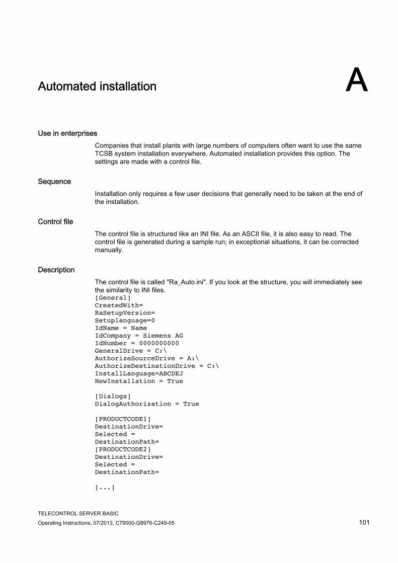
TELECONTROL SERVER BASIC Operating Instructions, 07/2013, C79000-G8976-C249-05 101
Automated installation A
Use in enterprises Companies that install plants with large numbers of computers often want to use the same TCSB system installation everywhere. Automated installation provides this option. The settings are made with a control file.
Sequence Installation only requires a few user decisions that generally need to be taken at the end of the installation.
Control file The control file is structured like an INI file. As an ASCII file, it is also easy to read. The control file is generated during a sample run; in exceptional situations, it can be corrected manually.
Description The control file is called "Ra_Auto.ini". If you look at the structure, you will immediately see the similarity to INI files. [General] CreatedWith= RaSetupVersion= Setuplanguage=0 IdName = Name IdCompany = Siemens AG IdNumber = 0000000000 GeneralDrive = C:\ AuthorizeSourceDrive = A:\ AuthorizeDestinationDrive = C:\ InstallLanguage=ABCDEJ NewInstallation = True [Dialogs] DialogAuthorization = True [PRODUCTCODE1] DestinationDrive= Selected = DestinationPath= [PRODUCTCODE2] DestinationDrive= Selected = DestinationPath= [...]

Automated installation
TELECONTROL SERVER BASIC 102 Operating Instructions, 07/2013, C79000-G8976-C249-05
Note
The parameters described below are examples from an INI file. The parameters may be different when installing TCSB.
[General] area General settings are made in the [General] area.
Parameters Value range Description CreatedWith Product series RaSetupVersion 0-5 Version of system setup Setuplanguage 0 – German
1 – English 2 – French 3 – Spanish 4 – Italian 5 – Chinese
IdName Name of the author IdCompany Company name GeneralDrive Drive for general data, for example "C:\" AuthorizeSourceDrive Source drive with license keys AuthorizeDestinationDrive Destination drive for license keys InstallLanguage ABCDEJ A – German
B – English C – French D – Spanish E – Italian J – Chinese
NewInstallation True/False True: Programs already installed are reinstalled.
False: An update is run.
[Dialogs] area Dialog windows are listed in the [Dialogs] area.
Parameters Value range Description DialogAuthorization True/False True: Dialog box becomes visible
False: Dialog box is not displayed.
usw.

Automated installation
TELECONTROL SERVER BASIC Operating Instructions, 07/2013, C79000-G8976-C249-05 103
[PRODUCTCODE1] area The product codes area contains the product code and the three following parameters. Examples of product codes are: [LICENSEMANAGER], [ACROREAD] or [S7PCED].
Parameters Value range Description DestinationPath Installation path
The installation path can be changed dynamically by a placeholder.
DestinationDrive Installation drive The installation drive can be changed dynamically by a placeholder.
Selected True/False Product selection If True, the program module is also installed even if it has already been installed on the system.
Description The control file is generated by the setup program automatically by making a trial installation.
The setup program can be controlled by a batch file.
Example of a batch file The batch file shown here generates the control file "Ra-Auto.ini".
cd sw
setup.exe /record
The lines of the batch file example have the following significance:
Line Meaning
1 The program changes to the "sw" folder. 2 The program starts the manual test installation and generates the
control file "Ra_Auto.ini" with the "/record" parameter. All user actions in the dialogs are stored there. The record action stops after the "component selection" and closes the program.

Automated installation
TELECONTROL SERVER BASIC 104 Operating Instructions, 07/2013, C79000-G8976-C249-05
Note
Note the following points relating to automatic installation: The path for the "Ra_Auto.ini" file can be set with the following instruction:
sw\setup.exe /silent=<drive>:\<required folder>\Ra_Auto.ini Unless a path is specified, the Windows directory is searched.
If additional questions arise or error messages are displayed during installation, a dialog opens.

TELECONTROL SERVER BASIC Operating Instructions, 07/2013, C79000-G8976-C249-05 105
Examples of the configuration data of SMS gateway providers B
Examples of the configuration data of SMS gateway providers The following table contains several examples of the configuration of the SMS gateway providers on the CMT. See also section Configuring SMS gateway providers (Page 90).
You can find out from your SMS gateway provider how to configure the e-mail for the wake-up SMS message.
Table B- 1 SMS gateway provider-related e-mail structures
SMS network provider E-mail address of the SMS gateway provider * Re ** Text ** E-Plus <SMS-NO>@smsmail.eplus.de <MSG> * <MSG> * O2 <SMS-NO>@o2online.de *** <MSG> * <MSG> * Smstrade <SMS-NO>@email2sms.smstrade.de <MSG> * #Identifikationkey
#Sendroute #Sender#
T-Mobile <SMS-NO>@t-mobile-sms.de <MSG> * <MSG> * Vodafone <SMS-NO>@vodafone-sms.de <MSG> * <MSG> *
* <SMS-NO> When configuring the e-mail address of the SMS gateway provider in the "Address" box, enter the placeholder "<SMS-NO>". TCSB then automatically enters the call number of the SIM card of the CP that originates from the CP configuration in STEP 7 and is transferred in the frame of the engineering station.
** All cells of the table with the entry "<MSG>" Enter the placeholder "<MSG>" in the "Re" or "Text" box. TCSB then automatically enters the correct message that is stored in the system and understood by the CP 1242-7. (This is the same text that is transferred in a wake-up SMS as the message text.) Wake-up SMS for the CP 1242-7 (Page 43)
*** The call number of the SIM card may only be entered in STEP 7 without the international country dialing code.
Activating the e-mail address To receive the e-mail, a personal mobile e-mail address needs to be activated with some network providers. To do this, send an activation SMS with a short number to your SMS network provider that you will find in the table below "Activation and deactivation SMS". You will receive a personal e-mail address via SMS that is normally made up of the phone number and the gateway name.
To activate your personal mobile e-mail address, send the special activation text to a short number of your SMS network provider.

Examples of the configuration data of SMS gateway providers
TELECONTROL SERVER BASIC 106 Operating Instructions, 07/2013, C79000-G8976-C249-05
You will receive a reply SMS with your personal mobile e-mail address that is made up of your phone number and the gateway name of your SMS network provider, for example: [email protected]
You will find examples of activation texts and short numbers of SMS network providers in the following table.
Note
Check with your network provider whether or not it is necessary to send activation and deactivation SMS messages. Your network provider will inform you of the texts and short number.
Table B- 2 Activation and deactivation SMS (examples)
E-Plus O2 Germany T-Mobile Vodafone Gateway name smsmail.eplus.de o2online.de t-mobile-sms.de vodafone-sms.de Enabling Send SMS with text to short number
Text: START Short number: 7676245
Text: OPEN Short number: 6245
Text: OPEN Short number: 8000
Text: OPEN Short number: 3400
Deactivating Send SMS with text to short number
Text: STOP Short number: 7676245
Text: STOP Short number: 6245
Text: CLOSE Short number: 8000
Text: CLOSE Short number: 3400

TELECONTROL SERVER BASIC Operating Instructions, 07/2013, C79000-G8976-C249-05 107
References C
Where to find Siemens documentation ● You will find the order numbers for the Siemens products of relevance here in the
following catalogs:
– SIMATIC NET Industrial Communication / Industrial Identification, catalog IK PI
– SIMATIC Products for Totally Integrated Automation and Micro Automation, catalog ST 70
You can request the catalogs and additional information from your Siemens representative.
● You will find SIMATIC NET manuals on the Internet pages of Siemens Automation Customer Support: Link to Customer Support (http://support.automation.siemens.com/WW/view/en)
Enter the entry ID of the relevant manual as the search item. The ID is listed below some of the reference entries in brackets.
As an alternative, you will find the SIMATIC NET documentation on the pages of Product Support:
10805878 (http://support.automation.siemens.com/WW/view/en/10805878)
Go to the required product group and make the following settings:
"Entry list" tab, Entry type "Manuals / Operating Instructions"
You will find the documentation for the SIMATIC NET products relevant here on the data medium that ships with some products:
– Product CD / product DVD or
– SIMATIC NET Manual Collection
/1/ SIMATIC NET GPRS/GSM modem SINAUT MD720-3 system manual Siemens AG Entry ID: 23117745

References /2/
TELECONTROL SERVER BASIC 108 Operating Instructions, 07/2013, C79000-G8976-C249-05
/2/ SIMATIC NET CP 1242-7 Operating Instructions Siemens AG entry ID: 61029644
/3/ SIMATIC NET TELECONTROL SERVER BASIC Operating Instructions Siemens AG entry ID: 50898745
/4/ SIMATIC NET SINAUT MICRO SC system manual Siemens AG Entry ID: 23119827
/5/ SIMATIC NET TS Gateway Operating Instructions Siemens AG Entry ID: 48548898
/6/ SIMATIC NET Commissioning PC Stations - Manual and Quick Start Configuration Manual Siemens AG entry ID: 13542666 (http://support.automation.siemens.com/WW/view/en/13542666)
TELECONTROL SERVER BASIC Operating Instructions, 07/2013, C79000-G8976-C249-05 109
Index
A Abbreviations/acronyms, 3 Activate, 67 Activated parameters, 82 Administrator password, 86
Loss, 86 Administrator privileges, 83 Authorized phone number, 94
B Browsing, 34
C Changing configuration data, 37 Connection generator, 75 Connection interrupted, 43 Connection mode, 47 Connection monitoring, 45 Current information, 4 Cyclic data exchange, 81
D Data block for process items, 27 Data types, 28 Database, 11 DB1, 27 DCOM settings, 23 DNS, 18
E Editing at the same time, 61 Examples of applications, 4
F FAQs, 4 Firewall settings, 20
G Glossary, 5 Grayed out boxes, 55
H Help, 60
I Image on the CP, 47 Importing projects, 38 Information, further (Internet link), 4 Interlock, Internet link, further information, 4 Invalid parameters, 57
K Keepalive timeout, 46
L Language selection, 93 Log files, 41
M Monitoring time, 47 Multiproject capability, 38 Multi-user capability, 38
N Name space, 34 Network settings, 22
O Online help, 60 Operating system, 17

Index
TELECONTROL SERVER BASIC 110 Operating Instructions, 07/2013, C79000-G8976-C249-05
P Password
Administrator, 54 Invalid entry, 53 Loss, 54 Overview, 49 Users, 88
Permanent, 79 Ports
Numbers, 95 Opening, 22
Process image, 47 Project import, 38 Protection concept, 10
R Read (OPC client), 47 Receive process image, 47 Reload (menu command), 61 Rights, 10 Runtime system, 51
S S7 systems, connectable, 9 S7-300, 9 Save, 67 Send process image, 47 Server password, 67 Service & Support, 5 Setting up OPC communication, 23 Settings, necessary, 22 SIMATIC NET glossary, 5 SINAUT MICRO SC, 68 SMS gateway, SMS gateway provider, 90 SMTP server, 97 Station monitoring, 80 Station number, MD720-3, 38 Station types, 72 Substitute server, 67 Syntax of OPC items, 27 System variables, 97
T TC_RECV, 47 TC_SEND, 47 Telecontrol Manager, 11
Telecontrol server, 9 TeleService via GPRS, 15 Temporary, 79 Time-of-day (dial-up), 49 Time-of-day synchronization, 80 Tolerance time, 46 Training, 5 Transferring configuration data, 37
U User name:Invalid entry, 53 User permissions, 10
V Validation, 57
W Wake-up SMS, 90 Write (OPC client), 48 Wrong entry, user name, 53