simatic s5 s5-155h programmable controller …...part i s5-155 h programmable controller (cpu 948r /...
TRANSCRIPT
Part IS5-155 H Programmable Controller(CPU 948R / 948RL)Instructions
Part IIData Handling Blocksfor the CPU 948R(Standard Function Blocks)Reference Manual
Part IIICOM 155HProgrammer Softwarefor Configuring the S5-155HProgrammable ControllerUser’s Guide
Part IVCC 155 HInstructions
S5-155HProgrammable Controller(CPU 948R / CPU 948RL)
Volume 1/2
Manual
This manual is part of the documentation packagewith the order number:6ES5998-4SR21
SIMATIC S5
08/99C79000-G8576-C197Edition 06

ii
#$.()0'*)/$).)*/$ .2#$#4*0.#*0'*. -1 /* ).0- 4*0-*2)+ -.*)'.! /4.2 ''./*
+-*/ //# +-*0/)*)) / ,0$+( )/# . )*/$ .- #$"#'$"#/ $)/# ()0'42-)$)"
/-$)"' )- (-& .!*''*2.*-$)"/*/# ' 1 '*!)" -
!Danger
$)$/ ./#/ /#. 1 - + -.*)'$)%0-4*-.0./)/$'+-*+ -/4(" 2$''- .0'/$!+-*+ -+- 0/$*).- )*//& )
!Warning
$)$/ ./#/ /#. 1 - + -.*)'$)%0-4*-.0./)/$'+-*+ -/4(" )- .0'/$!+-*+ -+- 0/$*).- )*//& )
!Caution
$)$/ ./#/($)*-+ -.*)'$)%0-4*-+-*+ -/4(" )- .0'/$!+-*+ -+- 0/$*).- )*//& )
Note
-2.4*0-// )/$*)/*+-/$0'-'4$(+*-/)/$)!*-(/$*)*)/# +-*0/#)'$)"/# +-*0/*-/*+-/$0'-
+-/*!/# *0( )//$*)
# 1$ .4./ ((4*)'4 . /0+)*+ -/ $)*)%0)/$*)2$/#/#$.()0'
)'4 .#*0' ''*2 /*$)./'')2*-&*)/#$. ,0$+( )/0'$!$ + -.*).-
!$) .+ -.*).2#*- 0/#*-$5 /**(($..$*)/*"-*0))/*/"$-0$/. ,0$+( )/)
.4./ (.$)*-) 2$/# ./'$.# .! /4+-/$ .)./)-.
*/ /# !*''*2$)"
!Warning
#$. 1$ )$/.*(+*) )/.(4*)'4 0. !*-/# ++'$/$*). .-$ $)/# /'*"*-/# / #)$' .-$+/$*))*)'4$)*)) /$*)2$/# 1$ .*-*(+*) )/.!-*(*/# -()0!/0- -.2#$##1 )++-*1 *-- *(( ) 4$ ( ).
#$.+-*0/)*)'4!0)/$*)*-- /'4).! '4$!$/$./-).+*-/ ./*- . /0+)$)./'' *-- /'4)*+ -/ )($)/$) .- *(( )
)- - "$./ - /- (-&.*!
#$-+-/$ .0.$)"!*-/# $-*2)+0-+*. .)4*/# -)( .$)/#$.*0( )/2#$#- ! -/*/- (-&.($"#/$)!-$)" 0+*)/# -$"#/.*!/# /- (-&*2) -.
#1 # & /# *)/ )/.*!/#$.()0'!*-"- ( )/2$/#/# #-2- ).*!/2- .-$ $) 1$/$*).))*/ +- '0 )/$- '42 ))*/"0-)/ !0''"- ( )/*2 1 -/# /$)/#$.()0'- - 1$ 2 - "0'-'4))4) ..-4*-- /$*).$)'0 $).0. ,0 )/ $/$*).0"" ./$*).!*-$(+-*1 ( )/- 2 '*(
Siemens AG 1994 #)$'/.0% //*#)"
Disclaimer of LiabilityCopyright Siemens AG 1994 All rights reserved
# - +-*0/$*)/-).($..$*)*-0. *!/#$.*0( )/*-$/.*)/ )/.$.)*/+ -($// 2$/#*0/ 3+- ..2-$// )0/#*-$/4!! ) -.2$'' '$' !*-(" .''-$"#/.$)'0$)"-$"#/.- / 4+/ )/"-)/*-- "$./-/$*)*!0/$'$/4(* '*- .$")- - . -1
$ ( ). - $#0/*(/$.$ -0)".70))/-$ ./ #)$& .# !/." $ /)0./-$ 0/*(/$.$ -0)"..4./ ( *./!#670 -) -"
Siemens Aktiengesellschaft C79000-G8576-C197
Safety Guidelines
Qualified Personnel
Correct Usage
Trademarks

Preface, Contents
Introduction to Installation andOperation of the S5-155H 1
H-Specific System Functions 2
CPU 948R/CPU 948RL 3
I/O Operating Modes andPermissible I/O Modules 4
CP/IP Operation in theS5-155H 5
Installation and Startup 6
Time Characteristics of the S5-155H 7
S5-155H Error Diagnostics 8Dynamic Response to Faults,Repair, Replacement andUpgrading 9
Sample Applications 10
Technical Specifications:IM 314R / IM 324R 11
Glossary 12
C79000-B8576-C197-06
S5-155HProgrammable Controller(CPU 948R / CPU 948RL)
Instructions(S5-155H, Part I)
SIMATIC S5

iS5-155H
C79000 B8576 C197 06
#$.()0'*)/$).)*/$ .2#$#4*0.#*0'*. -1 /* ).0- 4*0-*2)+ -.*)'.! /4.2 ''./*
+-*/ //# +-*0/)*)) / ,0$+( )/# . )*/$ .- #$"#'$"#/ $)/# ()0'42-)$)"
/-$)"' )- (-& .!*''*2.*-$)"/*/# ' 1 '*!)" -
!Danger
$)$/ ./#/ /#. 1 - + -.*)'$)%0-4*-.0./)/$'+-*+ -/4(" 2$''- .0'/$!+-*+ -+- 0/$*).- )*//& )
!Warning
$)$/ ./#/ /#. 1 - + -.*)'$)%0-4*-.0./)/$'+-*+ -/4(" )- .0'/$!+-*+ -+- 0/$*).- )*//& )
!Caution
$)$/ ./#/($)*-+ -.*)'$)%0-4*-+-*+ -/4(" )- .0'/$!+-*+ -+- 0/$*).- )*//& )
Note
-2.4*0-// )/$*)/*+-/$0'-'4$(+*-/)/$)!*-(/$*)*)/# +-*0/#)'$)"/# +-*0/*-/*+-/$0'-
+-/*!/# *0( )//$*)
# 1$ .4./ ((4*)'4 . /0+)*+ -/ $)*)%0)/$*)2$/#/#$.()0'
)'4 .#*0' ''*2 /*$)./'')2*-&*)/#$. ,0$+( )/0'$!$ + -.*).-
!$) .+ -.*).2#*- 0/#*-$5 /**(($..$*)/*"-*0))/*/"$-0$/. ,0$+( )/)
.4./ (.$)*-) 2$/# ./'$.# .! /4+-/$ .)./)-.
*/ /# !*''*2$)"
!Warning
#$. 1$ )$/.*(+*) )/.(4*)'4 0. !*-/# ++'$/$*). .-$ $)/# /'*"*-/# / #)$' .-$+/$*))*)'4$)*)) /$*)2$/# 1$ .*-*(+*) )/.!-*(*/# -()0!/0- -.2#$##1 )++-*1 *-- *(( ) 4$ ( ).
#$.+-*0/)*)'4!0)/$*)*-- /'4).! '4$!$/$./-).+*-/ ./*- . /0+)$)./'' *-- /'4)*+ -/ )($)/$) .- *(( )
)- - "$./ - /- (-&.*!
#$-+-/$ .0.$)"!*-/# $-*2)+0-+*. .)4*/# -)( .$)/#$.*0( )/2#$#- ! -/*/- (-&.($"#/$)!-$)" 0+*)/# -$"#/.*!/# /- (-&*2) -.
#1 # & /# *)/ )/.*!/#$.()0'!*-"- ( )/2$/#/# #-2- ).*!/2- .-$ $) 1$/$*).))*/ +- '0 )/$- '42 ))*/"0-)/ !0''"- ( )/*2 1 -/# /$)/#$.()0'- - 1$ 2 - "0'-'4))4) ..-4*-- /$*).$)'0 $).0. ,0 )/ $/$*).0"" ./$*).!*-$(+-*1 ( )/- 2 '*(
Siemens AG 1994 #)$'/.0% //*#)"
Disclaimer of LiabilityCopyright Siemens AG 1994 All rights reserved
# - +-*0/$*)/-).($..$*)*-0. *!/#$.*0( )/*-$/.*)/ )/.$.)*/+ -($// 2$/#*0/ 3+- ..2-$// )0/#*-$/4!! ) -.2$'' '$' !*-(" .''-$"#/.$)'0$)"-$"#/.- / 4+/ )/"-)/*-- "$./-/$*)*!0/$'$/4(* '*- .$")- - . -1
$ ( ). - $#0/*(/$.$ -0)".70))/-$ ./ #)$& .# !/." $ /)0./-$ 0/*(/$.$ -0)"..4./ ( *./!#670 -) -"
Siemens Aktiengesellschaft C79000-B8576-C197
Safety Guidelines
Qualified Personnel
Correct Usage
Trademarks

iiiS5-155HC79000-B8576-C197-06
Preface (How to Use This Manual)
This manual (Volume 1) describes the hardware, startup procedures andfunctions of the S5-155H programmable controller with CPU 948R orCPU 948RL (R standing for redundant).
Volume 2 of this manual covers programming of the S5-155H, including thewriting of the user program, and provides information regarding status,interrupt and error handling, latching functions and debugging aids.
The S5-155H differs from the standard version of the S5-155Hprogrammable controller because of its fault tolerance, which allows it to beoperated at a higher level of availability. The ”H” indicates that it has ahigher degree of availability than standard systems.
The S5-155H programmable controller system is distinguished by the”redundancy” of its central controller modules and, depending on how it isconfigured, of its I/O modules. The I/Os may even have triple redundancy. Ifa redundant system component fails during a process, the process can still becontrolled.
The S5-155H is a 1-out-of-2-system. The system has two CPUs. Faults arespecifically defined, thus making it impossible for a given fault to betransported from one subsystem to another. In order to attain a particularlyhigh degree of availability, the input/output area should also be configuredfor redundancy.

ivS5-155H
C79000-B8576-C197-06
!Warning
The S5-155H programmable controller (H system) is not a failsafe system,despite its high availability, fault tolerance and reaction-free design.
It must not be used in installations in which dangerous operating conditions– and thus danger to persons or the environment – could occur as a result ofa fault in the programmable controller (for example the highly improbabletotal failure of both central controllers).
In the case of such safety-related automation tasks, either a failsafeprogrammable controller (such as an S5-115F which has been type-tested bythe TÜV (German Technical Inspectorate) must be used, or the S5-155Hmust be equipped with suitable interlock controls or protective systemscapable of preventing the occurrence of dangerous operating conditions.
This manual is intended for engineers, programmers and maintenancepersonnel with a basic knowledge of SIMATIC S5 systems. If you have anyquestions that are not answered in the manual, please contact your localSiemens representative.
The following information on the contents of the various chapters is intendedto simplify the use of this part of the manual.
Note
The following restrictions apply to the S5-155H programmable controller:
The S5-155H does not have multiprocessor capabilities.
When writing your STEP 5 user program for the S5-155H, refer toSection 2.2 for information on avoiding errors or problems on initial startup.If you are careful to observe the restrictions listed there, you will be able touse all STEP 5 user programs which can run on the S5-155U on the S5-155Has well.
Chapter 1 gives you an overview of the main functions and characteristics ofthe S5-155U, and outlines its principles of operation. You will find moredetailed information in Chapter 2.
Chapter 2 presents detailed information on typical characteristics andindividual functions of the S5-155H, particularly on operating states andrestart types. Additional topics covered in this chapter include”event-controlled” synchronization and the system self-test for localizinghardware failures. The information on some topics goes into quite a bit ofdetail, so limit your reading as your necessity or interest dictates.
Target Group
Notes on theContents
Chapter 1:Introduction:SystemDescription
Chapter 2:H-Specific SystemFunctions
Preface

vS5-155HC79000-B8576-C197-06
Chapter 3 discusses the hardware and technical specifications for theCPU 948R and CPU 948RL central processing units. Some specific topicsare the modules’ installation, configuration, control elements and indicators.
Chapter 4 deals with the possible I/O modes in the S5-155U (redundant,switched, one-sided) and the modules which may be used in each case.
If you want to use redundant I/Os, you will find the module connections yourequire in Section 4.2. Section 4.2 also contains information on standardfunction blocks FB 40 and FB 43, which are used for analog value input, andon standard function block FB 41, which is used for analog value output.
Be sure to observe the instructions in this chapter when configuring andoperating your I/O modules!
Chapter 5 discusses the use of communications processors (CPs) andintelligent I/Os (IPs) in the S5-155U. It also contains all possibleconfigurations for redundant CP operation.
Chapter 5 also discusses special features regarding the use of data handlingblocks for the S5-155H, illustrating their usage in several sample STEP 5programs.
Chapter 6 discusses the procedures for installing the central controllers andI/Os as well as the IM 304/IM 324R parallel link and IM 304/IM 314Rinterface modules. It provides step-by-step instructions on configuring andstarting your S5-155H using your COM 155H programmer software.
Chapter 6 also describes the jumper settings on the IM 304, IM 314R andIM 324R.
Chapter 7 deals with the S5-155H’s time characteristics, most specificallythose instruction execution and system program runtimes which exceed thoseof the S5-155U due to the S5-155H’s fault tolerance.
Chapter 3:CPU 948R / 948RL
Chapter 4:I/O Modes andPermissibleModules
Chapter 5:Operating CPs/IPsin the S5-155H
Chapter 6:Installation andStartup
Chapter 7:TimeCharacteristics ofthe S5-155H
Preface
viS5-155H
C79000-B8576-C197-06
Chapter 8 describes all available error diagnostics options for the S5-155H. Itcontains details on the structure of the error data block (F-DB), in which thesystem program enters all recognized errors, as well as a list of error codesand their meanings. It also discusses the meaning of the H flag word, fromwhich you can read out information on the status of your PLC or enterinstructions for its control.
This chapter describes the response of the various modules to faults andfailures and shows you how to proceed when making the necessary repairs inorder to avoid interrupting operation.
Section 9.6 tells you how you can use certain on-line functions to replace orchange your user program on the memory card during operation.
Chapter 10 contains sample applications for S5-155H configurations with allthree types of I/Os. By implementing these examples, you will have a faulttolerant (H) system that you can use and expand to meet all yourrequirements.
Chapter 11 contains all the major technical specifications for the IM 314Rand IM 324R interface modules and the exact pinouts of the backplane andfront connectors. You will also find specifications in this chapter on thereadback delay which you should take into account when configuring yourdigital input/output modules.
The glossary defines 155H-specific terms.
The alphabetical index at the end of the manual will help you locate the mostimportant terms in the manual.
The remarks form at the very end of the manual is provided for yourcomments and recommendations.
Consult your local Siemens representative for information on training coursesto aid you in becoming familiar with this product.
Chapter 8:Error Diagnostics
Chapter 9:DynamicResponse toFaults, Repairs,Replacements andUpgrading
Chapter 10:TypicalApplications
Chapter 11:TechnicalSpecificationsIM 314R/IM 324R
Chapter 12:Glossary
Index
Remarks Form
Training
Preface

viiS5-155HC79000-B8576-C197-06
Note
This manual cannot cover all details and types of configuration for theprogrammable controller, nor can it cover all situations which can occur ininstallation, operation and maintenance.
If you require further information or have questions on your specificapplication which are not answered sufficiently here, please contact yourlocal Siemens representative.
It is recommended that you have the following reference material thatsupports the S5-155H system:
Catalog ST 54.4: S5-135U, S5-155U and S5-155H ProgrammableControllers (Order No. E86010-K4654-A111-A6) *
S5-135U/155U System Manual (Order No. 6ES5 998-0SH21) *
PG 685 Programmer (Order No. 6ES5 885-0SC21)) *
PG 710 Programmer (Order No. C79000–G8576–C170) *
PG 730 Programmer (Order No. C79000–G8576–C173) *
PG 750 Programmer (Order No. C79000–G8576–C750) *
PG 770 Programmer (Order No. C79000–G8576–C770) *
Programming Package for PC (Order No. 6ES5 896–0SC21) *
STEP 5 (Order No. C79000–G8576–C140) *
S5-DOS/ST Manual (Order No. C79000–G8576–C760) *
You will find a detailed introduction to STEP 5 programming and adescription of the functions of the S5-155U programmable controller andits I/O modules in
– Automating with the SIMATIC S5-155U by Hans Berger, Siemens AG,ISBN 3-8009-1561-8
* Available from your local Siemens representative
Reference Material
Preface

viiiS5-155H
C79000-B8576-C197-06
You can find up-to-date information about SIMATIC products on the Internetunder http://www.aut.siemens.de/.
Furthermore, the SIMATIC Customer Support team provides you withcurrent information and downloads which may be useful for users ofSIMATIC products:
On the Internet under http://www.aut.siemens.de/simatic-cs
Via the SIMATIC Customer Support Mailbox under the number(+49) (911) 895-7100
To dial in, use a modem with V.34 (28.8 kbps) capability whoseparameters you should set as follows: 8, N, 1, ANSI, or dial in usingISDN (x.75, 64 kbit).
You can reach SIMATIC Customer Support by phone using the number(+49) (911) 895-7000 and by fax using (+49) (911) 895-7002. You can alsosend inquiries by e-mail in the Internet or by mail to the above mailbox.
CurrentInformation
Preface

ixS5-155HC79000-B8576-C197-06
Notes on the CE Mark for SIMATIC S5
The following applies to the SIMATIC products described in this manual:
Products that carry the CE mark meet the requirements of EC Directive89/336/EEC “Electromagnetic Compatibility”.
The following area of use applies for SIMATIC S5 in accordance with thisCE mark:
Area of Application Requirements on
Noise emission Noise immunity
Industry EN 50081-2: 1993 EN 50082-2: 1995
The installation guidelines and safety notes given in the S5-135U/155USystem Manual must be observed during restart and operation of SIMATICS5 systems. The following regulations for the use of certain modules mustalso be observed.
To protect the modules from static discharge, the user must discharge hisbody’s electrostatic charge before opening a cabinet.
EC Directive onEMC 89/336/EEC
Areas of Use
Observing theInstallationGuidelines
Work on Cabinets
Preface

xS5-155H
C79000-B8576-C197-06
Additional measures are required when using the following modules.
A shielded signal cable is required for the following modules:
Order No. Module
6ES5 432-4UA12 Digital input module 432
6ES5 453-4UA12 Digital output module 453-4
6ES5 457-4UA12 Digital output module 457-4
6ES5 482-4UA11 Digital input/output module 482-4 for IP 257
A filter (SIFI C, B84113-C-B30 or equivalent) is required in the module’s 230 V AC load voltage supply of the forthe following modules:
Order No. Module
6ES5 436-4UA12 Digital input module 436-4
6ES5 436-4UB12 Digital input module 436-4
6ES5 456-4UA12 Digital output module 456-4
6ES5 456-4UB12 Digital output module 456-4
A filter (SIFI C, B84113-C-B30 or equivalent) is required in the module’s 24 V DC load voltage supply of the forthe following modules:
Order No. Module
6ES5 261-4UA11 IP 261 proportioning module
6ES5 432-4UA12 Digital input module 432
6ES5 453-4UA12 Digital output module 453-4
6ES5 457-4UA12 Digital output module 457-4
6ES5 465-4UA12 Analog input module 465-4
6ES5 470-4UB12 Analog output module 470-4
Notes onIndividual Modules
Preface

xiS5-155HC79000-B8576-C197-06
The products listed below fulfill the requirements of EC Directive 73/23/EEC“Low-Voltage Directive”. Adherence to this EC Directive was tested inaccordance with IEC 1131-2.
Name Order Number
Central controller 188 230V/18A 6ES5 188-3UA12
Central controller 188 230V/40A 6ES5 188-3UA22
Central controller 188 24V/18A 6ES5 188-3UA32
Central controller 188 24V/40A 6ES5 188-3UA52
Expansion unit 183U 230V/18A 6ES5 183-3UA13
Expansion unit 185U 230V/18A 6ES5 185-3UA13
Expansion unit 185U 220V/40A 6ES5 185-3UA33
Expansion unit 185U 24V/18A 6ES5 185-3UA23
Expansion unit 185 24V/40A 6ES5 185-3UA43
Expansion unit 183U 6ES5 183-3UA22
Digital input module 435-4 (24-60 V AC) 6ES5 435-4UA12
Digital input module 436-4 (115-230 V AC) 6ES5 436-4UA12
Digital input module 436-4 (115-230 V AC) 6ES5 436-4UB12
Digital input module 455-4 (24-60 V AC) 6ES5 455-4UA12
Digital input module 456-4 (115-230 V AC) 6ES5 456-4UA12
Digital input module 456-4 (115-230 V AC) 6ES5 456-4UB12
The SIMATIC S5-135U/155U and 155H programmable controllers and the155H central controller are “open type” equipment according to theIEC 1131-2 standard and therefore adhere to the EC Directive 73/23/EEClow-voltage directive and are UL/CSA certified as such.
To fulfill requirements for safe operation with regard to mechanical stability,flame retardance, stability, and shock-hazard protection, the followingalternative types of installation are specified:
Installation in a suitable cabinet
Installation in a suitable housing
Installation in a suitably equipped, enclosed operating area.
Installation in a cabinet is obligatory for the following listed products(reason: protection against accidental contact):
Name Order Number
Expansion unit 184U 6ES5 184-3UA11
Expansion unit 184U 6ES5 184-3UA21
S5-135U 24V/10A 6ES5 135-3UA42
Low-VoltageDirective73/23/EEC
SafetyRequirements forInstallation
Preface

xiiS5-155H
C79000-B8576-C197-06
In accordance with the above-mentioned EC Directive, the EU declarationsof conformity are held at the disposal of the competent authorities at theaddress below:
Siemens AGAutomation GroupAUT 14Postfach 1963D-92209 Amberg
Products that do not carry the CE mark fulfill the requirements and standardsas specified in the S5-135U/155U System Manual in the chapter on generaltechnical specifications.
Contrary to the specifications in the “General Technical Specifications” ofthe System Manual, the specifications listed below for noise immunity andelectromagnetic compatibility apply for modules which carry the CE mark.
The specifications are valid for devices which are installed in accordancewith the above-mentioned installation guidelines.
Noise immunity, electromagnetic compatibility (EMC)
RFI suppressionlimit value class
To EN 55011A 2)
Conducted interference on AC supply lines (230 V AC)to EN 61000-4-4 / IEC 1000-4-4 (burst)to IEC 1000-4-5between two lines (s pulses)between line and ground (s pulses)
2 kV
1 kV2 kV
DC supply lines (24 V DC) to EN 61000-4-4 / IEC 1000-4-4(burst) 2 kV
Signal lines to EN 61000-4-4 / IEC 1000-4-4 (burst) 2 kV 1)
Immunity to discharge of static electricity to EN 61000-4-2 /IEC 1000-4-2 (ESD) 2)
Immunity of 4 kV contact discharge (8 kV airdischarge) is ensured with proper installation (seeInstallation Guidelines in the S5-135U/155U SystemManual)
Immunity to electromagnetic RF field 2)
amplitude-modulated to ENV 50140 / IEC 1000-4-380 to 1000 MHz10 V/m80% AM (1kHz)
Immunity to electromagnetic RF field 2) pulse-modulated toENV 50204
900 MHz10 V/m50% ED
Immunity to high-frequency sinusoidal to ENV 50141 0.15 to 80 MHz10 V80% AM
1) Signal lines which do not serve to control the process, for example, connections to external I/O devices etc.: 1 kV2) When cabinet door is closed
Declaration ofConformity
Updated TechnicalData
Preface

xiiiS5-155HC79000-B8576-C197-06
Notes for Machine Manufacturers
The SIMATIC programmable controller is not a machine in the sense of theEC Directive on machines. Therefore, there is no declaration of conformityfor SIMATIC as regards the EC Directive 89/392/EEC on machines.
The EC Directive 89/392/EEC on machines controls machine requirements.Here, a machine is understood to be the entire sum of devices or partsinvolved (see also EN 292-1, paragraph 3.1).
SIMATIC is part of the electrical equipment for a machine and musttherefore be included in the procedure for checking conformity by themachine manufacturer.
The EN 60204-1 standard (machine safety, general requirements for theelectrical equipment for machines) applies to the electrical equipment formachines.
The following table should help you with the declaration of conformity andshows which criteria apply to EN 60204-1 (as at June 1993) for SIMATIC.
EN 60204-1 Subject/Criterion Remarks
Para. 4 General requirements Requirements are fulfilled if the machines areassembled/installed according to the installation guidelines.
See also the explanations on the previous pages.
Para. 11.2 Digital I/O interfaces Requirements are fulfilled.
Para. 12.3 Programmable equipment Requirements are fulfilled if the machines are installed inlockable cabinets to protect them from memory modificationsby unauthorized persons.
Para. 20.4 Voltage tests Requirements are fulfilled.
Introduction
EC Directive89/392/EEC onMachines
ElectricalEquipment forMachines toEN 60204
Preface

xivS5-155H
C79000-B8576-C197-06
Preface

xvS5-155HC79000-B8576-C197-06
Contents
1 Introduction to the Installation and Operationof the S5-155H Programmable Controller I/1-1. . . . . . . . . . . . . . . . . . . . . . . . . . . . . . . . .
1.1 Characteristics and Functions of the S5-155H Programmable Controller I/1-2
1.2 S5-155H Applications I/1-3. . . . . . . . . . . . . . . . . . . . . . . . . . . . . . . . . . . . . . . . . . . .
1.3 Redundant S5-155H Configuration I/1-4. . . . . . . . . . . . . . . . . . . . . . . . . . . . . . . . .
1.4 Method of Operation of the S5-155H I/1-7. . . . . . . . . . . . . . . . . . . . . . . . . . . . . . . S5-155H-Specific Functions I/1-7. . . . . . . . . . . . . . . . . . . . . . . . . . . . . . . . . . . . . . Operating States and Operating Principles of the S5-155H I/1-8. . . . . . . . . . . . Programming I/1-9. . . . . . . . . . . . . . . . . . . . . . . . . . . . . . . . . . . . . . . . . . . . . . . . . . . Program Processing I/1-9. . . . . . . . . . . . . . . . . . . . . . . . . . . . . . . . . . . . . . . . . . . . . Configuring and Error Diagnostics with COM 155H I/1-10. . . . . . . . . . . . . . . . . . .
1.5 S5-155H Hardware Configuration I/1-11. . . . . . . . . . . . . . . . . . . . . . . . . . . . . . . . . . Minimum Configuration I/1-13. . . . . . . . . . . . . . . . . . . . . . . . . . . . . . . . . . . . . . . . . . . Maximum Configuration I/1-14. . . . . . . . . . . . . . . . . . . . . . . . . . . . . . . . . . . . . . . . . .
1.6 Software I/1-15. . . . . . . . . . . . . . . . . . . . . . . . . . . . . . . . . . . . . . . . . . . . . . . . . . . . . . . 155H System Program I/1-15. . . . . . . . . . . . . . . . . . . . . . . . . . . . . . . . . . . . . . . . . . . STEP 5 User Program I/1-15. . . . . . . . . . . . . . . . . . . . . . . . . . . . . . . . . . . . . . . . . . .
2 H-Specific System Functions I/2-1. . . . . . . . . . . . . . . . . . . . . . . . . . . . . . . . . . . . . . . . . . . .
2.1 Method of Operation and Operating States of the S5-155H I/2-2. . . . . . . . . . .
2.2 Activating the Standby I/2-5. . . . . . . . . . . . . . . . . . . . . . . . . . . . . . . . . . . . . . . . . . .
2.3 Event-Driven Synchronization I/2-8. . . . . . . . . . . . . . . . . . . . . . . . . . . . . . . . . . . . .
2.4 Switchover from Standby to Master Controller I/2-10. . . . . . . . . . . . . . . . . . . . . . .
2.5 Self-Test I/2-12. . . . . . . . . . . . . . . . . . . . . . . . . . . . . . . . . . . . . . . . . . . . . . . . . . . . . . . Self-Test Strategy I/2-12. . . . . . . . . . . . . . . . . . . . . . . . . . . . . . . . . . . . . . . . . . . . . . .
3 CPU 948R/948RL I/3-1. . . . . . . . . . . . . . . . . . . . . . . . . . . . . . . . . . . . . . . . . . . . . . . . . . . . . . .
3.1 Technical Specifications of the CPU 948R/948RL I/3-2. . . . . . . . . . . . . . . . . . . .
3.2 CPU 948R/948RL Installation and Startup Procedures I/3-3. . . . . . . . . . . . . . . Removing and Inserting the Module I/3-3. . . . . . . . . . . . . . . . . . . . . . . . . . . . . . . . Control Elements and LEDs I/3-4. . . . . . . . . . . . . . . . . . . . . . . . . . . . . . . . . . . . . . Startup I/3-7. . . . . . . . . . . . . . . . . . . . . . . . . . . . . . . . . . . . . . . . . . . . . . . . . . . . . . . . . CPU 948R/948RL Interfaces I/3-9. . . . . . . . . . . . . . . . . . . . . . . . . . . . . . . . . . . . . . Specifications I/3-9. . . . . . . . . . . . . . . . . . . . . . . . . . . . . . . . . . . . . . . . . . . . . . . . . . .
3.3 Technical Specifications I/3-10. . . . . . . . . . . . . . . . . . . . . . . . . . . . . . . . . . . . . . . . . .

xviS5-155H
C79000-B8576-C197-06
4 I/O Operating Modes and Permissible I/O Modules I/4-1. . . . . . . . . . . . . . . . . . . . . . . .
4.1 Overview I/4-2. . . . . . . . . . . . . . . . . . . . . . . . . . . . . . . . . . . . . . . . . . . . . . . . . . . . . . .
4.2 Redundant I/Os (Overview) I/4-6. . . . . . . . . . . . . . . . . . . . . . . . . . . . . . . . . . . . . . . Interface Modules and Expansion Units I/4-6. . . . . . . . . . . . . . . . . . . . . . . . . . . . Digital and Analog I/O Modules I/4-6. . . . . . . . . . . . . . . . . . . . . . . . . . . . . . . . . . . . Overview of Redundant I/O Types I/4-7. . . . . . . . . . . . . . . . . . . . . . . . . . . . . . . . .
4.3 Redundant Digital Inputs/Outputs (DIs/DQs) I/4-10. . . . . . . . . . . . . . . . . . . . . . . . 4.3.1 Redundant DIs without Error Locating Facility I/4-10. . . . . . . . . . . . . . . . . . . . . . . 4.3.2 Redundant DIs with Error Locating Facility I/4-11. . . . . . . . . . . . . . . . . . . . . . . . . .
Testing the Error Locating Facility I/4-11. . . . . . . . . . . . . . . . . . . . . . . . . . . . . . . . . . 4.3.3 Redundant Three-Channel DIs I/4-13. . . . . . . . . . . . . . . . . . . . . . . . . . . . . . . . . . . . 4.3.4 Configuring Redundant Process Interrupts (DI 0) I/4-15. . . . . . . . . . . . . . . . . . . . 4.3.5 Redundant DQs without Error Locating Facility (LF) I/4-16. . . . . . . . . . . . . . . . . . 4.3.6 Redundant DQs with Error Locating Facility (DQ Type 10) I/4-17. . . . . . . . . . . .
Testing the Error Locating Facility I/4-17. . . . . . . . . . . . . . . . . . . . . . . . . . . . . . . . . . 4.3.7 Redundant DQ with Error Locating Facility and 3 Readback DIs
(DQ Type 11) I/4-20. . . . . . . . . . . . . . . . . . . . . . . . . . . . . . . . . . . . . . . . . . . . . . . . . . . Testing the Error Locating Facility I/4-21. . . . . . . . . . . . . . . . . . . . . . . . . . . . . . . . . .
4.4 Redundant Analog Input/Outputs (AIs/AQs) I/4-23. . . . . . . . . . . . . . . . . . . . . . . . . Direct I/O Access I/4-23. . . . . . . . . . . . . . . . . . . . . . . . . . . . . . . . . . . . . . . . . . . . . . .
4.4.1 Principle of the Redundant 1-out-of-2 Analog Inputs I/4-23. . . . . . . . . . . . . . . . . . 4.4.2 Redundant AI 463: FB 32 I/4-25. . . . . . . . . . . . . . . . . . . . . . . . . . . . . . . . . . . . . . . . 4.4.3 Redundant AI 466: FB 33 I/4-30. . . . . . . . . . . . . . . . . . . . . . . . . . . . . . . . . . . . . . . . 4.4.4 Redundant AIs: FB 40 I/4-35. . . . . . . . . . . . . . . . . . . . . . . . . . . . . . . . . . . . . . . . . . . 4.4.5 Principle of the Redundant 1-out-of-3 AIs I/4-39. . . . . . . . . . . . . . . . . . . . . . . . . . . 4.4.6 Redundant AI 463: FB 35 I/4-41. . . . . . . . . . . . . . . . . . . . . . . . . . . . . . . . . . . . . . . . 4.4.7 Redundant 3-Channel AI 466: FB 36 I/4-46. . . . . . . . . . . . . . . . . . . . . . . . . . . . . . . 4.4.8 Three-Channel Redundant AIs: FB 43 I/4-51. . . . . . . . . . . . . . . . . . . . . . . . . . . . . .
4.5 Redundant Analog Outputs I/4-55. . . . . . . . . . . . . . . . . . . . . . . . . . . . . . . . . . . . . . . One-Sided Analog Outputs I/4-55. . . . . . . . . . . . . . . . . . . . . . . . . . . . . . . . . . . . . . . Redundant Analog Outputs I/4-55. . . . . . . . . . . . . . . . . . . . . . . . . . . . . . . . . . . . . . .
4.5.1 Redundant 2-Channel AQs without Error Locating Facility I/4-55. . . . . . . . . . . . 4.5.2 Redundant 2-Channel AQs with Error Locating Facility I/4-55. . . . . . . . . . . . . . . 4.5.3 FB for 2-Channel Redundant AQs (FB 41) I/4-59. . . . . . . . . . . . . . . . . . . . . . . . . .
4.6 One-Sided I/Os I/4-63. . . . . . . . . . . . . . . . . . . . . . . . . . . . . . . . . . . . . . . . . . . . . . . . . Interface Modules and Expansion Units (EUs) I/4-63. . . . . . . . . . . . . . . . . . . . . . . Digital and Analog Input/Output Modules I/4-64. . . . . . . . . . . . . . . . . . . . . . . . . . .
4.7 Switched I/Os I/4-65. . . . . . . . . . . . . . . . . . . . . . . . . . . . . . . . . . . . . . . . . . . . . . . . . . . Interface Modules and Expansion Units (EUs) I/4-66. . . . . . . . . . . . . . . . . . . . . . . Digital and Analog I/O Modules I/4-66. . . . . . . . . . . . . . . . . . . . . . . . . . . . . . . . . . . .
4.8 Hybrid I/O Configurations I/4-67. . . . . . . . . . . . . . . . . . . . . . . . . . . . . . . . . . . . . . . . .
4.9 FB 192 (IM308C-R) for Redundant and One-Sided Operation I/4-68. . . . . . . . . 4.9.1 General I/4-68. . . . . . . . . . . . . . . . . . . . . . . . . . . . . . . . . . . . . . . . . . . . . . . . . . . . . . . . 4.9.2 Standard Function Block FB 192 I/4-69. . . . . . . . . . . . . . . . . . . . . . . . . . . . . . . . . . 4.9.3 Technical Specifications I/4-75. . . . . . . . . . . . . . . . . . . . . . . . . . . . . . . . . . . . . . . . . . 4.9.4 Error Messages I/4-76. . . . . . . . . . . . . . . . . . . . . . . . . . . . . . . . . . . . . . . . . . . . . . . . .
Contents - Part I

xviiS5-155HC79000-B8576-C197-06
5 Operation of Communications Processors and Intelligent I/Os in the S5-155H I/5-1
5.1 Intelligent I/Os in the S5-155H I/5-2. . . . . . . . . . . . . . . . . . . . . . . . . . . . . . . . . . . .
5.2 One-Sided CP/IP Configurations I/5-3. . . . . . . . . . . . . . . . . . . . . . . . . . . . . . . . . . Communications Processors (CPs/IPs) I/5-3. . . . . . . . . . . . . . . . . . . . . . . . . . . . .
5.3 Switched CP/IP Configurations I/5-4. . . . . . . . . . . . . . . . . . . . . . . . . . . . . . . . . . . . CPs/IPs I/5-4. . . . . . . . . . . . . . . . . . . . . . . . . . . . . . . . . . . . . . . . . . . . . . . . . . . . . . . .
5.4 Redundant Communications Processor (CP) Configurations I/5-5. . . . . . . . . .
6 Installation and Startup I/6-1. . . . . . . . . . . . . . . . . . . . . . . . . . . . . . . . . . . . . . . . . . . . . . . . .
6.1 Installing the S5-155H I/6-2. . . . . . . . . . . . . . . . . . . . . . . . . . . . . . . . . . . . . . . . . . .
6.2 Configuring the IM 304/IM 324R Parallel Link I/6-5. . . . . . . . . . . . . . . . . . . . . . .
6.3 Configuring One-Sided I/Os and Putting Them Into Operation I/6-8. . . . . . . . .
6.4 Configuring Switched I/Os and Putting Them Into Operation I/6-10. . . . . . . . . .
6.5 Configuring Redundant I/Os and Putting Them Into Operation I/6-15. . . . . . . . .
6.6 S5-155H Responses to Faults/Errors I/6-17. . . . . . . . . . . . . . . . . . . . . . . . . . . . . .
7 Time Characteristics of the S5-155H I/7-1. . . . . . . . . . . . . . . . . . . . . . . . . . . . . . . . . . . . .
7.1 Statement Execution Times for the S5-155H I/7-2. . . . . . . . . . . . . . . . . . . . . . . .
7.2 System Program Runtimes I/7-3. . . . . . . . . . . . . . . . . . . . . . . . . . . . . . . . . . . . . . . Increased S5-155H Runtimes I/7-3. . . . . . . . . . . . . . . . . . . . . . . . . . . . . . . . . . . . . S5-155H Restart Time I/7-3. . . . . . . . . . . . . . . . . . . . . . . . . . . . . . . . . . . . . . . . . . .
7.3 Dynamic Response on Standby Activation I/7-4. . . . . . . . . . . . . . . . . . . . . . . . . .
7.4 Interrupt Response Time I/7-5. . . . . . . . . . . . . . . . . . . . . . . . . . . . . . . . . . . . . . . . .
8 S5-155H Error Diagnostics I/8-1. . . . . . . . . . . . . . . . . . . . . . . . . . . . . . . . . . . . . . . . . . . . . .
8.1 Troubleshooting and Error Handling in the S5-155H I/8-2. . . . . . . . . . . . . . . . . .
8.2 Error Data Block (E-DB) I/8-4. . . . . . . . . . . . . . . . . . . . . . . . . . . . . . . . . . . . . . . . . . Notes on Error Diagnostics I/8-21. . . . . . . . . . . . . . . . . . . . . . . . . . . . . . . . . . . . . . . Evaluating the Error Data Block I/8-22. . . . . . . . . . . . . . . . . . . . . . . . . . . . . . . . . . . Error Messages from the CP 523 I/8-22. . . . . . . . . . . . . . . . . . . . . . . . . . . . . . . . . .
8.3 H Flag Doubleword I/8-25. . . . . . . . . . . . . . . . . . . . . . . . . . . . . . . . . . . . . . . . . . . . . .
8.4 Error Organization Block OB 37 I/8-26. . . . . . . . . . . . . . . . . . . . . . . . . . . . . . . . . . .
8.5 The H Flag Word I/8-27. . . . . . . . . . . . . . . . . . . . . . . . . . . . . . . . . . . . . . . . . . . . . . . .
9 Dynamic Response to Faults, Repair, Replacement and Upgrading I/9-1. . . . . . . . .
9.1 Failure and Repair of the CPU and Parallel Links I/9-2. . . . . . . . . . . . . . . . . . . . Replacing the Central Processing Unit I/9-2. . . . . . . . . . . . . . . . . . . . . . . . . . . . . Replacing the Interface Modules (IMs) I/9-2. . . . . . . . . . . . . . . . . . . . . . . . . . . . . Replacing the IM 30x Interface Modules in the CC(Excepting those used for the Parallel Link) I/9-3. . . . . . . . . . . . . . . . . . . . . . . . . Replacing the IM 30x – IM 31x Connecting Cable I/9-3. . . . . . . . . . . . . . . . . . . .
9.2 Failure and Repair of Expansion Units (EUs) I/9-4. . . . . . . . . . . . . . . . . . . . . . . .
9.3 Failure and Repair of I/O Modules I/9-5. . . . . . . . . . . . . . . . . . . . . . . . . . . . . . . . .
Contents - Part I

xviiiS5-155H
C79000-B8576-C197-06
9.4 Failure and Repair of CP/IP Modules I/9-6. . . . . . . . . . . . . . . . . . . . . . . . . . . . . . .
9.5 Standby-Master Switchover I/9-8. . . . . . . . . . . . . . . . . . . . . . . . . . . . . . . . . . . . . . .
9.6 Replacing the Memory Card During Operation I/9-10. . . . . . . . . . . . . . . . . . . . . . .
9.7 Upgrading the CPU 948R’s RAM or Version Number I/9-11. . . . . . . . . . . . . . . . .
10 Typical Applications I/10-1. . . . . . . . . . . . . . . . . . . . . . . . . . . . . . . . . . . . . . . . . . . . . . . . . . . .
10.1 Task and Required Resources I/10-2. . . . . . . . . . . . . . . . . . . . . . . . . . . . . . . . . . . .
10.2 Installing the Hardware I/10-3. . . . . . . . . . . . . . . . . . . . . . . . . . . . . . . . . . . . . . . . . . . System Configuration I/10-3. . . . . . . . . . . . . . . . . . . . . . . . . . . . . . . . . . . . . . . . . . . . Establishing a CC-to-CC Parallel Link I/10-3. . . . . . . . . . . . . . . . . . . . . . . . . . . . . . Installing the I/O Bus I/10-5. . . . . . . . . . . . . . . . . . . . . . . . . . . . . . . . . . . . . . . . . . . . .
10.3 Configuring Switched I/Os I/10-6. . . . . . . . . . . . . . . . . . . . . . . . . . . . . . . . . . . . . . . . Calling COM 155H I/10-6. . . . . . . . . . . . . . . . . . . . . . . . . . . . . . . . . . . . . . . . . . . . . . Initializing the Operating System (COM 155H) I/10-7. . . . . . . . . . . . . . . . . . . . . . . Setting the System Size I/10-8. . . . . . . . . . . . . . . . . . . . . . . . . . . . . . . . . . . . . . . . . . Configuring Digital Inputs I/10-9. . . . . . . . . . . . . . . . . . . . . . . . . . . . . . . . . . . . . . . . . Configuring Digital Outputs I/10-9. . . . . . . . . . . . . . . . . . . . . . . . . . . . . . . . . . . . . . . Transferring Configuring Data (DX 1) I/10-10. . . . . . . . . . . . . . . . . . . . . . . . . . . . . . Starting Up the PLC I/10-10. . . . . . . . . . . . . . . . . . . . . . . . . . . . . . . . . . . . . . . . . . . .
10.4 Configuring One-Sided I/Os I/10-11. . . . . . . . . . . . . . . . . . . . . . . . . . . . . . . . . . . . . . .
10.5 Configuring Redundant I/Os I/10-12. . . . . . . . . . . . . . . . . . . . . . . . . . . . . . . . . . . . .
10.6 Redundant Point-To-Point Link I/10-17. . . . . . . . . . . . . . . . . . . . . . . . . . . . . . . . . . . Two-Channel Redundant Point-to-Point Link I/10-17. . . . . . . . . . . . . . . . . . . . . . . Switched Redundant Point-to-Point Link I/10-23. . . . . . . . . . . . . . . . . . . . . . . . . . . Reactivating a Failed CP (In-Cycle Synchronization) I/10-26. . . . . . . . . . . . . . . .
11 Technical Specifications:IM 314R / IM 324R I/11-1. . . . . . . . . . . . . . . . . . . . . . . . . . . . . . . . . . . . . . . . . . . . . . . . . . . . . . .
11.1 Technical Specifications of the IM 314R Interface Module I/11-2. . . . . . . . . . . . .
11.2 Technical Specifications of the IM 324R Interface Module I/11-5. . . . . . . . . . . . .
11.3 Readback Delays I/11-8. . . . . . . . . . . . . . . . . . . . . . . . . . . . . . . . . . . . . . . . . . . . . . .
12 Glossary I/12-1. . . . . . . . . . . . . . . . . . . . . . . . . . . . . . . . . . . . . . . . . . . . . . . . . . . . . . . . . . . . . . .
A Abbreviations I/A-1. . . . . . . . . . . . . . . . . . . . . . . . . . . . . . . . . . . . . . . . . . . . . . . . . . . . . . . . . .
Index I/Index-1. . . . . . . . . . . . . . . . . . . . . . . . . . . . . . . . . . . . . . . . . . . . . . . . . . . . . . . . . . . . . . .
Contents - Part I

I/1-1S5-155HC79000-B8576-C197-06
Introduction to the Installation andOperation of the S5-155H ProgrammableController
The S5-155H is a fault-tolerant programmable controller for machine andplant control. It is an event-synchronized master-standby system with a1-out-of-2 structure. A data link connects line the master to the standbycontroller.
This introduction is intended to familiarize you with some typicalcharacteristics of the S5-155H, and is aimed especially at those users who arealready acquainted with the S5-155U. It has been assumed that the reader isfamiliar with the S5-155U’s functionality.
1

I/1-2S5-155H
C79000-B8576-C197-06
1.1 Characteristics and Functions of the S5-155H ProgrammableController
The S5-155H with CPU 948R is based on the S5-155H withCPU 946R/947R, but its system performance capabilities have beenexpanded and considerably improved:
The most important innovations in the S5-155H with CPU 948R are
– its expandability to as many as 192 redundant analog I/O channels,
– its fault-tolerant analog outputs,
– its utilization of the CPU 948’s functionality,
– higher processing speed,
– page access to one-sided IP/CP permitted,
– more accurate error locating of configuration errors in the list of thecyclic DB/DX,
– the range limit for the redundant/one-sided I/O must no longer beconfigured, i. e. switched, one-sided and redundant I/Os can be mixed.
Configurable redundancy enables economical solutions (one, two orthree-channel I/O operation).
Redundant operation of digital and analog I/O modules.
NON-STOP operation of redundant I/Os in the S5-155H. The systemprogram supports non-stop operation of redundant I/Os with extensiveself-tests for detecting and localizing errors quickly.
On-line repair of defective I/Os, thus avoiding interruptions inprogrammable controller operation.
The support of the COM 155H programmer software, a special programpackage with its own reference manual, in system configuring and errordiagnostics.
Important
The S5-155H can be operated non-stop.
This means it tolerates the first failure of each redundant hardwarecomponent. The failed components can be repaired without interruptingoperation.
Please note that the S5-155H will fail a) partially or b) completely when thestandby component fails before the original fault has been rectified.
a) A partial failure will result if; e.g., after a redundant input module fails,its standby module also fails before the original module can be repaired.
b) The system will fail completely if; e.g., after a central controller fails,the second central controller also fails before the first can be repaired.
The faster a component is repaired, the lower the risk of further failures.
S5-155HPerformanceCharacteristics
Introduction to the Installation and Operation of the S5-155H Programmable Controller

I/1-3S5-155HC79000-B8576-C197-06
1.2 S5-155H Applications
The S5-155H can perform extensive, complex automation tasks whileproviding a high degree of fault tolerance.
In the majority of cases, fault-tolerant systems continue operation even whenone or more faults result in failure of peripheral or central controllercomponents.
Fault-tolerant systems should always be used when it is necessary to keep theprobability of a total control system failure (for example a cooling pumpcontrol system) to a minimum.
Based on cost, applications for a fault-tolerant programmable controllersystem can be divided into two categories:
High production downtime costs per unit of time. Example: Assemblyline production.
High costs even for brief production downtimes. Example: Industrialprocesses.
!Danger
The S5-155H must never be used in plants or installations in which aprogrammable controller fault or malfunction could result in danger topersons, machines or the environment. Safety-related automation tasks ofthis nature require the use of a programmable controller which wasprototype-tested by the TÜV (German Technical Inspectorate), or theprogrammable controller must be equipped with suitable interlocks orprotective systems which prohibit the occurrence of dangerous operatingstates.
Please note that there is a distinct difference between a fault-tolerant systemand a failsafe system.
A fail-safe system also has a redundant component configuration, but entersthe STOP mode (in the case of two-out-of-two redundancy) in the event of afault.
Fault-TolerantSystems
Fail-Safe Systems
Introduction to the Installation and Operation of the S5-155H Programmable Controller

I/1-4S5-155H
C79000-B8576-C197-06
1.3 Redundant S5-155H Configuration
The S5-155H (central controller) always has a redundant configuration. Itconsists of two S5-135U/155U central controllers. Three (combinable) I/Oredundancy structures are possible:
One-channel I/O module configuration (”switched”);
Two-channel (1-of-2) I/O module configuration;
Three-channel (1-of-3) module configuration.
A one-channel I/O module configuration should be used when the applicationrequires only central controller redundancy (Figure 1-1).
Centralcontroller B
CPU948R Central
controller A
Expansion unit
I/Os
CPU948R
P r o c e s s
Figure 1-1 Structure of the S5-155H with One-Channel I/O Module Configuration (”Switched Mode”)
A two-channel or three-channel configuration should be implementedwhenever requirements dictate that input and output modules should alsohave the highest possible degree of fault tolerance (Figures 1-2 and 1-3).
Structure
One-ChannelConfiguration
Multi-ChannelConfiguration
Introduction to the Installation and Operation of the S5-155H Programmable Controller

I/1-5S5-155HC79000-B8576-C197-06
CPU948R Central
controller ACentralcontroller B
CPU948R
P r o c e s s
Figure 1-2 Structure of the S5-155H with Two-Channel Redundant I/O Module Configuration
CPU948R Central
controller ACentralcontroller B
Expansion unit
I/Os
CPU948R
P r o c e s s
Sensors, digital or analog
Figure 1-3 Structure of the S5-155H with Three-Channel Redundant Module Configuration
Introduction to the Installation and Operation of the S5-155H Programmable Controller

I/1-6S5-155H
C79000-B8576-C197-06
The three configurations can be combined as needed, thus making it possibleto create configurations tailored to meet the fault-tolerance requirements ofany given application.
For those parts of a plant which do not require fault tolerance, expansionunits (EUs) can be interfaced to each of the central controllers on a1-out-of-1 basis (as for a one-channel S5-155U).
CPU948R Central
controller B
CPU948R Central
controller A
P r o c e s s
Expansion unit
I/Os
Figure 1-4 Structure of the S5-155U with One-Channel and Two-Channel Redundant I/O Module Configuration(Hybrid Configuration)
HybridConfiguration
Introduction to the Installation and Operation of the S5-155H Programmable Controller

I/1-7S5-155HC79000-B8576-C197-06
1.4 Method of Operation of the S5-155H
Each of the two central controllers (the master and the standby) contains aCPU 948R central processing unit whose firmware autonomously handles allfunctions specific to the S5-155H. The most important of these are:
Event-controlled synchronization of the two central controllers
Self-tests for memory, processors, central controller link and S5 bus
Switching from master CC to standby CC
Error handling and
Processing of operator entries on the programmer (automatic transfer ofdata to the other central controller).
The central controller which was powered up and successfully performed itsself-test first assumes the role of master CC.
The overview below briefly describes master-standby operation of theS5-155H for one-channel and two-channel configurations of the I/O.
Operation for one-channel (’switched’) configuration:
Master CC Standby CC
Reads the input signals (PII)
Passes the input signals to thestandby CC at the beginning ofeach cycle
Scans the user program as perthe synchronization points
Compares the process outputimages (PIQs) and
Generates output signals
Receives the input signals fromthe master CC
Scans the user program as perthe synchronization points
Compares the process outputimages (PIQs)
PII = Process input image, PIQ = Process output image
Operation for two-channel configuration:
Master CC Standby CC
Reads the input signals (PII)
Unifies the process input images(PIIs)
Scans the user program as perthe synchronization points
Compares the process outputimages (PIQs)
Generates output signals
Reads the input signals (PII)
Unifies the process input images(PIIs)
Scans the user program as perthe synchronization points
Compares the process outputimages (PIQs) and
Generates output signals
S5-155H-SpecificFunctions
Introduction to the Installation and Operation of the S5-155H Programmable Controller

I/1-8S5-155H
C79000-B8576-C197-06
The master controller in a fault-tolerant S5-155H programmable controllersystem can assume the following states while controlling a process:
Solo mode
The master controller controls the process alone; the standby is inactive.
Activation of the standby
The master transfers the current data and the current program to thestandby.
Redundant mode
The master controls the process and the standby runs concurrently in an”updated” state, always ready to take over.
Error search mode
The master controls the process and the standby executes the self-test.
The figure below illustrates the principle of operation, and in particular theinteraction between the S5-155H’s subunits.
RAMcontentsA/B
Subunit A Subunit B
PIQ A/B
Sync.
PII A/B
Interruptsynchroni–zation
Sync.
Sync.
Cyclic controlSynchronization of the subunitsRead in PII: One-sided (A),
Switched (if master)Redundant
Exchange PII with subunit B
Compare two-channel inputs: Discrepancy monitoring Error handling Identical signal generation
OB 1, user program
Block boundary
Direct I/O access
Timer scans
Self-test slice: RAM, firmware, processor, RAM comparison
Exchange and compare PIQwith subunit BReport error if not identical
Output PIQ:One-sided (A), switched (if master),two-channel, with test on edge change
Cyclic controlSynchronization of the subunitsRead in PII: One-sided (B),
Switched (if master)Redundant
Exchange PII with subunit A
Compare two-channel inputs: Discrepancy monitoring Error handling Identical signal generation
OB 1, user program
Block boundary
Direct I/O access
Timer scans
Self-test slice: RAM, firmware, processor, RAM comparison
Exchange and compare PIQ with subunit AReport error if not identical
Output PIQ:One-sided (B), switched (if master),two-channel, with test on edge change
Figure 1-5 S5-155H Principle of Operation
Operating Statesand OperatingPrinciples of theS5-155H
Introduction to the Installation and Operation of the S5-155H Programmable Controller

I/1-9S5-155HC79000-B8576-C197-06
The following is typical of S5-155H operation:
In a one-channel (switched) configuration, only the master is active.
In a two-channel configuration, the master and the standby are both active(parallel operation).
The operating system also ensures an ordered functional sequence whenusing a hybrid configuration (one-channel or multi-channel).
Essentially, the S5-155H is programmed in the same way as an S5-155U.With the exception of the operations for multi-processor mode, all STEP 5operations are allowed.
The programmer (PG) is used in exactly the same way as for the S5-155U. Inredundant systems, it is connected to only one of the central controllers, andthe data entered on it are passed automatically to the second CC.
In addition to normal cyclic scanning of the process images in the subunits’CPUs, additional functions for synchronization and for the interchange andcomparison of data and, where applicable, of status information are requiredduring processing of the user program in the S5-155H.
The same user programs run in both subunits (master and standby). Masterand standby execute in event-driven synchronism. The 155H systemprogram ensures that both subunits work with identical data (see Section 2.3,”Event-Driven Synchronization”).
At the beginning of each cycle, master and standby read the process imagesof the one-sided and redundant inputs assigned to them. The process image ofthe switched inputs is read in only by the master. The two subunits thenexchange the entire process input image.
The 155H’s system program uses a separate timer for each redundant input.These timers are used to monitor discrepancies. If a specific input signaldiffers between the master and the standby, this discrepancy is tolerated forthe period of time programmed by the user (10 ms to 320 s). Thesediscrepancy timers are updated once per cycle, following exchange of thePII. If the two input signals are still not the same when the set time haselapsed, the defective input in the master or standby is located and entered inthe error data block.
Self-Test Functions To detect errors as quickly as possible, the 155H’s system program executesself-test functions during restart and cyclic program processing. Thesefunctions test the contents and state of memory, processors and I/Os, andmake comparisons between the subunits. The functions are processedcyclically in ”test slices”. The number of test slices may be configured by theuser. Please note that the normal scan time of your STEP 5 program isincreased by the execution time of the test slices.
Programming
ProgramProcessing
Event-SynchronousUser ProgramProcessing
Process InputImage (PII)
DiscrepancyMonitoring
Introduction to the Installation and Operation of the S5-155H Programmable Controller

I/1-10S5-155H
C79000-B8576-C197-06
When the user program in OB 1 has been completely processed, the masterand the standby exchange and compare process output images. If there is adiscrepancy, an error is reported. The standby controller enters the ”Errorsearch” mode and the master continues in ”Solo” mode. The process outputimages are output to the I/Os.
The S5-155H has a longer scan time than the S5-155U due to the155H-specific auxiliary functions. Some of the reasons for the increased scantime are listed below:
The self-test; the user can configure the required time between 2 ms and38 ms per cycle.
The time the 155H operating system needs to process the process images(approx. 15 ms) and
The time needed by the synchronization commands to process Transferstatements.
Example: The ’L PW’ statement is also called upon to transfer the loadedI/O word to the second CC.
The time needed to process the Transfer statement depends on the numberof synchronization commands in the user program. The typical timeneeded is approximately 5 % to 15 % of the S5-155U’s scan time.
The COM 155H software supports both configuring and error diagnostics viathe following functions:
Configuring of H-specific data; this includes
– specifying which I/O modules are redundant and which are not,
– specifying the data block in which the system is to report errors(the so-called error DB), and
– defining the hardware configuration.
Error diagnostics, i. e., reading out, interpreting and displaying theinformation found in the error DB
Making a hardcopy printout to document the configured data
General system handling tasks.
Process OutputImage (PIQ)
Scan Cycle Time
Configuring andError Diagnosticswith COM 155H
Introduction to the Installation and Operation of the S5-155H Programmable Controller

I/1-11S5-155HC79000-B8576-C197-06
1.5 S5-155H Hardware Configuration
The following table shows you which modules can be inserted in which slots.
Slot No. 3 11 19 27 35 43 51 59 67 75 83 91 99 107 115 123 131 139 147 155 163
Module Type
CPU 948R,UR 11, 12, 21, 22, 51
CPU 948R,UR 13, 23, 53
CP 5XX, CP 143,CP 5430, CP 54311)
IM 300-5IM 301-51)
IM 300-3, IM 301-3IM 304, IM 308,IM 308B, IM 308C
IM 3072)
DI, DO,AI, AO1)
IP 241USW, IP244IP 2521)
IP 240, IP 241,IP 242, IP 242A,IP 242B, IP 243,IP 2811)3)4), IP 288
IM 304/IM 324R
IP 260,IP 261
Load current supply–9511)
Electrical connection Mechanical width
1. Note the installation width for each particular module; some may take up more slots to the
right (see Catalog ST 54.1).
2. Note the jumper setting on the IM 307; interrupt transfer is only possible in slots 107 to 131.
3. Use in slots 27, 43, 59, 139 and 147 provides only a very restricted functionality as no
interrupts are wired.
4. IP 243 without DA or AD converter in slots 27, 43, 59, 139 and 147.
Possible CC 188Configurations forS5-155H with theCPU 948R
Introduction to the Installation and Operation of the S5-155H Programmable Controller

I/1-12S5-155H
C79000-B8576-C197-06
The following table shows you which modules can be inserted in which slots.
Slot No. 3 11 19 27 35 43 51 59 67 75 83 91 99 107 115 123 131 139 147 155 163
Module Type
CommunicationsProcessors (CP)
IM 314 R
IM 300-5C
IM 308
IM 308-B/C 1)
DI, DO,AI, AO
Signal-processingmodules (IP)
See current Catalog ST 54.1 for slot numbers
1) IM 308C enabled in the EG 185U only for switched I/O in H system.
PossibleConfigurations forthe EU 185U
Introduction to the Installation and Operation of the S5-155H Programmable Controller

I/1-13S5-155HC79000-B8576-C197-06
The fault-tolerant S5-155H programmable controller consists of standardcomponents of the SIMATIC S5 range.
The S5-155H’s minimum configuration consists of two S5-135U/155Ucentral controllers (master and standby), each with
one built-in power supply unit and
one CPU 948R.
The two central controllers are interconnected over a parallel interface. Thisinterface consists of an IM 304 module (in one central controller, thesubunit B), an IM 324R (in the other central controller, the subunit A), and a721 connecting cable. The parallel interface is used for data exchangebetween the master and the standby.
IM 324 R:Slot 131
Subunit A
Subunit B
IM 304:Slot 131
Figure 1-6 Minimum Configuration of the S5-155H
MinimumConfiguration
Introduction to the Installation and Operation of the S5-155H Programmable Controller

I/1-14S5-155H
C79000-B8576-C197-06
Building on the minimum configuration, the system can be expanded byadding S5 modules:
Digital and analog input/output modules (I/Os)
Communications processors (CPs)
Intelligent I/Os (IPs)
A maximum of sixteen expansion units (EUs) with up to eight I/O buses canbe connected to one S5-155H.
Central
Central
SynchronizationStatusBlocks
I/O modulesone-sided,assigned to CC Bredundant
CPU948R
I/O modulesone-sided,assigned to CC A,redundant
COM H
324R
I/O modulesCP, IPswitched
304
CPU948R
304
IM
IM
314R
314R
304
IM
IM
Figure 1-7 Sample S5-155H Configuration, System Structure
MaximumConfiguration
Introduction to the Installation and Operation of the S5-155H Programmable Controller

I/1-15S5-155HC79000-B8576-C197-06
1.6 Software
The 155H system program is a modified 155U system program, expanded toinclude a number of redundancy-specific functions. It is an integral part ofthe central controller, which means that the whole program memory of theS5-155U is available for the user program.
Important
The 155H system program reserves
– the data block DX 1
– the error data block (number specified by user)
– the RAM data block (number specified by user)
– the H flag word (number specified by user)
Only those functions are listed here which have been added to the 155H butare not part of the 155U system program. These and all other functions aredescribed in detail in the Programming Guide for the CPU 948R (Volume 2of this manual).
The expansions and modifications in the 155H system program affect thefollowing system characteristics and capabilities:
Function See Chapter/Section
– Mode of operation and status– Activating the standby controller– Event-driven synchronization– Switching from standby to master controller– Self-test– Error search mode– Redundant I/Os– Operation with the IM 314R– Time characteristics– Online functions– Troubleshooting and repairs
2.12.22.32.42.58.1
4.2, 4.3, 4.411.1
7Volume II / 10
9
The various functions are discussed in more detail in the sections indicated.
In the S5-155U, you can use all STEP 5 user programs that can execute in theS5-155U, provided you observe the following.
155H SystemProgram
STEP 5 UserProgram
Introduction to the Installation and Operation of the S5-155H Programmable Controller

I/1-16S5-155H
C79000-B8576-C197-06
Important
The following applies to the S5-155H:
– The S5-155H can no longer be used in multiprocessor mode.
– The following integral special functions cannot be executed on theS5-155U: OB 126, OB 200, OB 202 to 205, OB 223.
– The SED and SEE operations are only for multiprocessor mode,and therefore not permissible for the S5-155H.
In addition, please note the following when writing your user program for theS5-155H:
Use only the STEP 5 operations LT and LCT (not LIR, TIR, LDI andTDI) for word-based access to timers.
The parameters ”155U” (or interruptability at instruction boundaries) and”Warm restart” must not be selected in DX 0. A DX 0 error resulting inthis way causes the CPU to stop.
You cannot access operating system data words RS 96 to RS 99 via theSTEP 5 user program. Instead, use special-function organization blockOB 121 or 151 to read or set the date and time; only in this way can yoube sure that the same date/time will be entered in both subunits.
Only the master has direct access to switched I/Os in the restart routine.
Note the following on startup:
All DBs/DXs whose contents are changed in interrupt service routinesmust be entered in the interrupt DB/DX transfer data lists usingCOM 155H.
All DBs/DXs whose contents are changed in the cyclic program must alsobe entered in the cycle DB/DX transfer data list with COM 155H.
Unusual feature of the S5-155H as regards T PY/T PW and addressingerrors:
If a timeout (QVZ) and an addressing error (ADF) are present when theoperation is executed (for unconfigured, non-existent I/Os), then onlyQVZ is reported in Solo mode whereas both QVZ and ADF are reportedin Redundant mode.
STEP 5 Program
Startup
Introduction to the Installation and Operation of the S5-155H Programmable Controller

I/1-17S5-155HC79000-B8576-C197-06
An error is reported when one of the following special functions is executedwhile the master controller is activating the standby: GDB, GXDX, OB 124”Delete blocks”, OB 125 ”Generate blocks”, OB 254 and OB 255 ”Transferdata blocks”. Error code ”4F”: ”Function currently impermissible becausestandby is being activated”, is forwarded in accumulator register 1-LL.
The CPU 948R is the upwardly-compatible successor to the CPU946R/947R. The following points should be noted:
DX1 must be converted with the help of COM 155H V3.0.
The structure of the error DB has been changed.
H flag control bit 3 is disabled for the user.
Special Functions:OB 124, 125, 254and 255
Differencesbetween theCPU 948R and theCPU 946R/947R
Introduction to the Installation and Operation of the S5-155H Programmable Controller

I/1-18S5-155H
C79000-B8576-C197-06
Introduction to the Installation and Operation of the S5-155H Programmable Controller

I/2-1S5-155HC79000-B8576-C197-06
H-Specific System Functions
This chapter describes in detail all typical system features and individualS5-155H functions.
2

I/2-2S5-155H
C79000-B8576-C197-06
2.1 Method of Operation and Operating States of the S5-155H
On startup or restart, the S5-155H assumes one of the operating states shownin Figure 2-1:
Solo mode:The master subunit alone scans the user program and controls the process;the standby subunit is inactive.
Activating the standby:The master subunit passes the current data to the standby.
Error search mode:The master subunit scans the user program and controls the process; thestandby subunit executes the self-test.
Redundant mode:The master subunit controls the process; the standby subunit runs in parallel(”updated” mode), and is ready to take over at any time.
PLC failureinSolo mode
Transition to RUN
PLC or subunit (re)start
Problemlocated
Standby (re)start
Standby malfunction
Solomode
mode
Subunit(re)start
PLCSTOP
Figure 2-1 S5-155H Modes and Transitions
Operating States
H-Specific System Functions

I/2-3S5-155HC79000-B8576-C197-06
In a fault-tolerant programmable controller system, identical user programsrun in both subunits. The subunits are ”event-synchronized”; that is, onlythose events which could produce different internal ”states” in the twocentral controllers cause the controllers to be synchronized. The internal”state” is determined by the states of the memory areas used (process image,flags, counters, timers and data blocks).
Examples of such ’events’ are:
Direct access operations to one-sided, switched or redundant I/Os Timer scans Process interrupts and Timed interrupts
Figure 2-2 shows how an S5-155H with CPU 948R handles I/Os.
1. Each subunit reads the one-sided inputs assigned to it, and the redundantinputs. The ’switched’ inputs are read only by the master, which alsoupdates the input image for both subunits and generates a unified inputimage.
2. One timer location is set aside for each redundant digital input, and isupdated by the operating system. The CPU 948R function block sets asideone timer location per redundant analog input which is updated once perFB call. This timer is used as discrepancy watchdog for the redundantdigital inputs; that is, the CPU 948R tolerates non-matching input signalsfor a time period defined by the user (20 ms to 320 s).
3. If a continuous signal discrepancy is ascertained, the defective input islocated in subunit A or B by means of an I/O test, entered in the error DB,and passivated.
In order to increase the fault tolerance of the system, errors/faults must bedetected and eliminated if possible before the redundant component fails;that is, faults/errors in the standby controller should be detected before themaster controller fails. For this purpose, extensive self-test functions formemory, processors and I/Os have been integrated in the CPU 948R.
4. The S5-155H self-test functions run in their entirety every time a subunitis restarted. In cyclic mode, the tests are executed in ’slices’ whosenumber per cycle (scan cycle time increase) can be stipulated by the user.
During the self-test, as during other time-consuming operating systemfunctions, interrupts are permitted at 2 ms intervals.
5. OB 1, which, like every user program, is synchronized on an event-drivenbasis, is then invoked.
6. After each program pass, the two output images (PIQs) of the subunits arecompared. If they are not identical, an error is reported.
7. The output images are output to the I/O. Also, in the case of two-channeldigital outputs, a readback digital input uses a ”0” to ”1” edge to locatestuck at 0 errors.
The operating system synchronizes and processes system interrupts, processinterrupts and timed interrupts at block boundaries. Direct access operationsto switched I/Os are immediately synchronized and processed.
S5-155H Principleof Operation
Processing theUser Program
H-Specific System Functions

I/2-4S5-155H
C79000-B8576-C197-06
In the case of one-sided and redundant I/Os, the operating system inputsignals are also exchanged and compared. Timer scans are immediatelysynchronized and unified by copying the master’s timer value to the standby.
LPW
End of OB 1
PIQ comparison
Output redundantPIQWait for master
Output one-sidedPIQ
Self-test approx. 2 ms
Read one-sided PII
Read redundant PII
DIs identical? Mark firstdiscrepancy
Start of OB 1
LPW
PIQ
CC A(in this case the standby)
CC B(in this case the master)
Transfer switched PII
Replace
one-sided PII
Replace
one-sided PII
Data
Op. system sync.
Instruction sync.
Op. system sync.
Op. system sync.
IM 324R
Instruction sync.
End of OB 1
PIQ comparison
Output redundantPIQOutput redundantPIQ
Output one-sidedPIQ
Self-test approx. 2 ms
Read switched PII
Read one-sided PII
Read redundant PII
DIs identical? Mark firstdiscrepancy
Start of OB 1
Mod
e
Mod
e
Figure 2-2 Cyclic Process Image Updating of the Inputs and Outputs
As regards restarts, be sure to refer to the appropriate chapter in theCPU 948R Programming Guide, (Volume 2 of this manual), where you willfind information on all S5-155H restart modes:
Cold restart: OB 20
Manual warm restart with memory: OB 21
Automatic warm restart with memory: OB 22
Activation of this online function does not restart the whole S5-155H system,but only the subunit to which the programmer is connected. The COM 155Hfunction ”RUN SYS” , in contrast, restarts the whole system.
Programming thePLC RestartRoutine
Online FunctionSTART
H-Specific System Functions

I/2-5S5-155HC79000-B8576-C197-06
2.2 Activating the Standby
Activating the standby means matching the internal states of the twosubunits. After the standby has been enabled in the Restart routine, it sendsan ”activation request” to the master.
As soon as the request has been made, the two subunits are checked for anydiscrepancies. This involves checking the following to make sure that thereare no differences between the two controllers:
1. The RAM capacity of the standby CPU and the master CPU are the same.
2. The operating system code in master and standby are identical.
3. The checksums of the user code chips are identical.
4. The start addresses of the STEP 5 user blocks are identical.
5. The checksums of the static user data (except for the DB and DX datablocks in cyclic and interrupt-driven program processing) are identical.
6. The checksums of the memory cards in master and standby are identical.
If there is no match in checks a., b. and f., the standby controller reports anerror and stops.
If there is no match in tests c. to e., the contents of the master’s CPU arecopied to the standby’s CPU. The activation procedure (the copying of thecontents of the master controller’s CPU to the standby controller’s CPU) isspread over several cycles.
Once the standby controller has been activated (the static data in master andstandby are identical), master and standby execute an automaticdepassivation routine; this procedure does not erase the error information inthe error DB.
The standby controller executes its restart self-test. It then waits to be”updated”; that is, it waits for the arrival of all dynamic data from the mastercontroller.
During the standby activation phase, the red STOP LED and the green RUNLED flash alternately on the standby CPU (at approximately 1/2 secondintervals). During the restart test phase, both LEDs show a steady light.
Updating of the standby controller increases the duration of a mastercontroller cycle on a one-shot basis by a specifiable amount of time. Theupdating instant can be chosen on a process-dependent basis; bit position ”2”in the H flag word’s control byte is reserved specifically for this purpose(see Section 8.5). You can disable the updating procedure by setting this bit,or enable updating by resetting it. This permits you to choose a non-criticalprocess state for the one-shot scan cycle time increase.
Note, however, that disabling updating increases downtimes; that is, itdecreases the system’s availability or fault tolerance. When the bit is reset tore-enable updating, the enable becomes valid with the next cycle.
Activation Process
Restart Self-Testand UpdatingProcess
H-Specific System Functions

I/2-6S5-155H
C79000-B8576-C197-06
Important
Updating of the standby controller increases the duration of a mastercontroller scan cycle on a one-shot basis by the amount of time specified inthe configuration data. To minimize the scan time increase as much aspossible, enter only those DB and DX data blocks during the configuringphase with COM 155H which will be modified in the user program (forexample DBs in OB 1), and which must therefore be transferred within onecycle when activating the standby.
Since timed and process interrupts are not disabled when activating thestandby, also specify the numbers of those data blocks modified in interruptservice routines (such as DBs in OB 13).
The controller is updated as follows. The 155H system program
transfers all configured ”cycle DBs/DXs”, 1)
disables all interrupts,
transfers all configured interrupt DBs/DXs, 1)
transfers all flags, counters, timers, RS, RT, RI and RJ locations, the errorDB, and the RAM DB,
switches to ”Redundant mode” and
enables the interrupts.
1) Data blocks processed both in the cyclic program and in an interruptOB need be listed only once under ”interrupt DBs/DXs”.
With regard to the above, also please refer to Section 3.3 in Part III of thisVolume entitled ”Initializing the Activation of the Standby”.
Once the standby has been activated and updating completed, both subunitsenter the event-synchronized cyclic mode.
The following overview (Figure 2-3) summarizes the activities of the masterand standby CPUs during the activation and updating process.
Updating theStandby Controller
H-Specific System Functions

I/2-7S5-155HC79000-B8576-C197-06
Interrupt DB, DX, flags,
timers, counters, RT, RS, RI,RJ locations, error DB, RAM DB
Update user program
(using data from master)
– Compare memory configuration
– Compare memory card checksum
– Generate block list in DB 0
– Clear process input image
– Clear process output image
– Reset flags, timers, counters
– Reset digital/analog I/Os(2 x 128 bytes each)
– Reset interprocessor communication flags(256 bytes)
– Clear ISTACK/BSTACK
Start self-test
– DB 1 available:transfer interprocessor communicationinput/output flags from DB 1 to standby
– Transfer info to DX 0
– Transfer configuration data to DX 1
– Call user interface OB 20, 21, 22(if available)
Status/System Program Functions:
STANDBY(activation)
Update dynamic data
Update dynamic data
Remove BASPEnable interrupt
Status/System Program Functions:
MASTER(cyclic operation)
OB 1H Op. sys.
OB 1H Op. sys.
FB, PB ...
Interpreting of DX 1
for error messagesOB 1H Op. sys.
Synchronization
Data exchange
PIQ, RAM comparison
OB 1
H Op. sys.
Cycl. DB, DX
Automaticdepassivation *)
Testing of IM304 – IM324R parallel link
OB 1
H Op. sys.
OB 1H Op. sys.
Interruptdisable
H Op. sys.
Interruptenable
*) Static error image is reset. The error messages in the error DB remain unchanged. The operatingsystem re-enters any unrectified errors in the error DB if those same errors re-occur.
Figure 2-3 Standby Activation and Updating Sequence
H-Specific System Functions

I/2-8S5-155H
C79000-B8576-C197-06
2.3 Event-Driven Synchronization
Both subunits are synchronized to ensure bumpless switching between masterand standby at all times.
The synchronization procedure used in the S5-155H is known as”event-driven synchronization”, which means that the subunits aresynchronized whenever an event occurs which could result in the twosubunits having different internal states; for example different processimages, flags, timers or communications data. These events include:
Direct access to I/Os
Timer scans
System interrupts
Process interrupts
Timed interrupts
The operating system performs subunit synchronization in order to ensurecomplete transparency of the user program. The user is not aware of this.This means that you can write your program in the same way as for anS5-155U in single-processor mode. The only difference is that thesynchronization procedure increases the normal S5-155U execution times ofthe STEP 5 operations used for direct I/O access, timer scans and blockchanges (refer to the STEP 5 List of Operations). The execution times of theother operations are not affected.
In the S5-155H, block-granular interruptibility is the only permissible mode.This means that interrupts are serviced only between blocks. In order toprevent different ”internal states” from occurring, entry into the interrupt OBis made at the same place each time, namely, at a ”synchronization point”. Inthe CPU 948R, the synchronization point for interrupts is always the nextblock change. Input byte IB 0 can be used for process interrupts.
In each subunit, a check is made at every synchronization point to make surethe other subunit is functioning. Depending on the result of the check, aswitchover from the standby to the master controller is performed and themessage ”Standby failure” output.
The synchronization procedure is timed at each synchronization point. Theoperating system sets the watchdog timer to 30 ms. A check is also made ateach synchronization point to make sure that both subunits are executing thesame statement (comparison of OP codes). If they are not, the standbycontroller stops and a ”synchronization error” is reported.
Switchover fromMaster to Standby
Synchronizationand ProgramProcessing
Synchronizationand InterruptServicing
Synchronizationand SystemMonitoring
H-Specific System Functions

I/2-9S5-155HC79000-B8576-C197-06
At the end of OB 1, the entire process output image (PIQ) in bothCPU 948Rs is immediately compared and the non-passivated PIQ (redundantPIQ, switched PIQ, one-sided PIQ) output. The self-test is then run.
Following the self-test, the process input image (PII) is read in (redundantPII, switched PII, one-sided PII). The PII is exchanged and unified. OB1 isthen re-called.
The required functions are described in detail in Chapter 4.
Due to the inaccuracy of quartz timing, CMOS clocks of the two subunitsmay begin to show a discrepancy after a while (at a rate of approximately 1second per day), which can cause problems when transferring from thestandby controller to the master. The error codes entered in the error DBshow the exact sequence of occurrences, but the time stamp could provemisleading.
For this reason, the two subunit clocks are compared cyclically, and theoperating system automatically corrects the standby controller’s clock whenthe discrepancy exceeds 0.05 seconds.
If a ZYK error occurs in Redundant mode, the standby controller alwaysstops, while at the same time the scan cycle time in the master controller isretriggered. The subunit which continues its operation in Solo modefunctions like an S5-155U; that is, the response to a subsequent ZYK errordepends on OB 26.
Process ImageUpdating
AutomaticResetting of theStandbyController ’s Clock
Cycle Errors
H-Specific System Functions

I/2-10S5-155H
C79000-B8576-C197-06
2.4 Switchover from Standby to Master Controller
The synchronization procedure ensures bumpless switching from standby tomaster controller at all times. This means:
Transfer does not affect process output signals. There is no loss of information in communications with CPs/IPs. User program processing is not affected.
Switchover from standby to master takes place in the following instances:
1. Failure of the master CC (BASP, NAU or STOP switch);
2. Initial error search of both subunit CPUs unsuccessful (see ”Error searchmode”)
3. First failure of a master controller’s IM 314R when the standby controllerhas access to a larger number of IM 314R interface modules than themaster.
4. First failure of a master controller’s I/O bus (wire break, for instance) orfailure of an IM 304 when the standby controller has access to a largernumber of IM 314R interface modules than the master.
5. First failure of a switched I/O module
6. User issues a software request (H flag control byte) for transfer fromstandby to master controller.
7. If more than 30 timeouts occur in redundant I/O bytes in the subunit ofthe master within one PLC cycle.
In cases c. to g., the new standby CPU does not stop, but continuesfunctioning as standby controller.
The standby controller checks the operational status of the master controllerat each synchronization point. Failure of a master controller is detected at thehardware level by evaluating the S5 bus signals BASP and NAU in the IM324R parallel interface module. The standby CPU’s operating system detectsthe failure of the master controller at the next synchronization point, andbranches to a routine which executes the following functions:
Switches over the I/O buses of all IM 314R modules;
Switches all two-channel I/Os to single-channel operation;
Switches the operating system to Solo mode; that is, no subunitsynchronization;
If the synchronization point is a direct I/O access operation, that operationwill be retried.
Following a standby-to-master switchover, the S5-155H with CPU 948Roperates in Solo mode. The H error system OB is invoked; you can programthe desired response in this OB.
The following occurs with the I/Os allocated to the failed subunit:
PIQ and PII are set to zero No ’ADF’ error is reported when this PIQ/PII is accessed Timeout is reported in the event of direct access to one of these I/Os.
Switching Criteria
FunctionalSequence of aSwitchover fromStandby to Master
H-Specific System Functions

I/2-11S5-155HC79000-B8576-C197-06
2.5
Essentially, the S5-155H achieves its high degree of fault tolerance throughits multi-channel capability coupled with speedy repair following detectionof a malfunction. If a controller is considered to be fault tolerant only whenits status is that of ”no malfunction”, it follows that the fault tolerance of anH system is increased further by its self-test (Figure 2-4).
The diagram and the formula below show that a self-test increases the faulttolerance of an automation system. The amount of time in which thecontroller malfunctions is reduced to a minimum.
1
3
2
Status: Description:1 No controller malfunctions2 Controller malfunction3 Controller failure
MTBF
Fault tolerance for ”No controller malfunctions”status:
V =MTBF + MTTR + MFDT
MTBF
Fault rate = 1/MTBFRepair rate = 1/MTTRFault detection rate = 1/MFDT, MFDT = T/2 (T= Self-test cycle)
1
MTTR1
MFDT1
Figure 2-4 Importance of the Self-Test to Fault Tolerance
An H system’s highest priority is fault detection and fault localization. This isrequired in order to control the fault. The S5-155H’s self-test routines run inboth CPUs. They detect and localize hardware failures in a minimal amountof time and with little programming effort. To localize a fault, it is necessaryonly to find out which modules are faulty and to replace them.
Which self-test routines execute depends on the S5-155H’s operating status.
Self-test in the Restart routine
The entire self-test is run when a central controller is restarted. If a faultis detected at this stage, the CPU stops. An error message is entered in theerror data block. Because the self-test takes longer than one minute, it canbe skipped on a warm restart of the master controller (see ”H FlagControl Byte”).
During execution of the self-test in the Restart routine, the RUN andSTOP LEDs on the frontplate show a steady light. A complete self-test isrun in all Restart modes.
Self-Test and FaultTolerance
Self-Test Strategy
H-Specific System Functions

I/2-12S5-155H
C79000-B8576-C197-06
Self-test in cyclic mode
Each time OB 1 is processed (once per cycle), part of the self-test isexecuted in small slices (2 ms test slices). The self-test therefore runs,transparent for the other software, in the background until a hardwarefailure is detected.
You can configure the execution time for the self-test in increments of2 ms. If you define a value which exceeds a test slice, the occurrence of atimed or process interrupt is queried after each test slice and the interruptserviced before the next test slice. The execution time for the self-testincreases in this case by the time needed to service the interrupt.
A value of between 1 and 20 may be defined as the number of test slicesto be executed per PLC cycle (refer to Chapter 3 in Part III of thisVolume, entitled ’Configuring and Initializing’). These values correspondto self-test execution times of from 2 to 40 ms.
In a test run, the CPU 948R-1 can have a maximum of 10,000 test slices,the CPU 948R-2 a maximum of 30,000 and the CPU 948RL a maximumof 5000.
In the S5-155H, such important system components as CPU, memory, I/Osand communications links are continually tested and monitored.
CPU test
Includes testing of STEP 5 operations, timers, CMOS clock, interruptmask and the scan time monitor.
Firmware/RAM test
Comparison of the RAM in both subunits and a checksum test of the OB,SB, PB, FB, FX blocks and of the constants DB/DX. Also a RAM test forall variable DB/DX.
I/O bus test with IM 314R
Tests for short-circuits and breaks in the 721 I/O bus cable to theIM 314R.
I/O bus test for page addressing
Page addressing is tested in cyclic mode once in every complete test run.The test detects the following faults:
– A CP/IP reacts to (acknowledges) not only its own interface number,but also to the other 255 interface numbers.
– An acknowledgement is issued by an unassigned interface number. Allunassigned interface numbers are tested. The test is also executedonce on each restart.
IM 304R/IM 324R parallel interface test
The parallel interface’s dual-port RAM is tested on both subunits A andB. The purpose of this test is to locate any short-circuits or cable/wirebreaks.
Tested SystemComponents
H-Specific System Functions
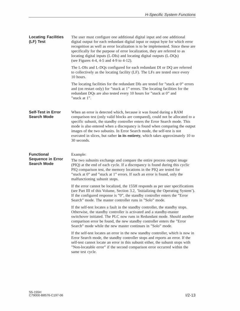
I/2-13S5-155HC79000-B8576-C197-06
The user must configure one additional digital input and one additionaldigital output for each redundant digital input or output byte for which errorrecognition as well as error localization is to be implemented. Since these arespecifically for the purpose of error localization, they are referred to aslocating digital inputs (L-DIs) and locating digital outputs (L-DQs)(see Figures 4-4, 4-5 and 4-9 to 4-12).
The L-DIs and L-DQs configured for each redundant DI or DQ are referredto collectively as the locating facility (LF). The LFs are tested once every10 hours.
The locating facilities for the redundant DIs are tested for ”stuck at 0” errorsand (on restart only) for ”stuck at 1” errors. The locating facilities for theredundant DQs are also tested every 10 hours for ”stuck at 0” and”stuck at 1”.
When an error is detected which, because it was found during a RAMcomparison test (only valid blocks are compared), could not be allocated to aspecific subunit, the standby controller enters the Error Search mode. Thismode is also entered when a discrepancy is found when comparing the outputimages of the two subunits. In Error Search mode, the self-test is notexecuted in slices, but rather in its entirety, which takes approximately 10 to30 seconds.
Example:
The two subunits exchange and compare the entire process output image(PIQ) at the end of each cycle. If a discrepancy is found during this cyclicPIQ comparison test, the memory locations in the PIQ are tested for”stuck at 0” and ”stuck at 1” errors. If such an error is found, only themalfunctioning subunit stops.
If the error cannot be localized, the 155H responds as per user specifications(see Part III of this Volume, Section 3.2, ’Initializing the Operating System’).If the configured response is ”0”, the standby controller enters the ”ErrorSearch” mode. The master controller runs in ”Solo” mode.
If the self-test locates a fault in the standby controller, the standby stops.Otherwise, the standby controller is activated and a standby-masterswitchover initiated. The PLC now runs in Redundant mode. Should anothercomparison error be found, the new standby controller enters the ”ErrorSearch” mode while the new master continues in ”Solo” mode.
If the self-test locates an error in the new standby controller, which is now inError Search mode, the standby controller stops and reports an error. If theself-test cannot locate an error in this subunit either, the subunit stops with”Non-locatable error” if the second comparison error occurred within thesame test cycle.
Locating Facilities(LF) Test
Self-Test in ErrorSearch Mode
FunctionalSequence in ErrorSearch Mode
H-Specific System Functions

I/2-14S5-155H
C79000-B8576-C197-06
H-Specific System Functions

I/3-1S5-155HC79000-B8576-C197-06
CPU 948R/948RL
This chapter contains the hardware description and technical specificationsfor the CPU 948R and CPU 948RL central processing units. In addition tocomments regarding application, you will find all information and dataneeded for installing the modules and putting them into operation. Thisincludes information on inserting and removing the modules as well as oncontrol elements and indicators on the modules’ frontplate.
Details on programming can be found in the Programming Guide for theCPU 948R (Volume 2 of this manual).
You can insert a memory card containing your user program into theCPU 948R and CPU 948RL.
Note
Note that only this chapter deals specifically with the CPU 948RL and thatthe differences between the CPU 948R and the CPU 948RL are onlydescribed in this chapter.
Where only the CPU 948R is mentioned in other chapters in this manual, theinformation there also applies in the same way to the CPU 948RL with theexception of the differences listed in this chapter.
3

I/3-2S5-155H
C79000-B8576-C197-06
3.1 Technical Specifications of the CPU 948R/948RL
The CPU 948R and 948RL can be used in S5-135U/155H central controllers.Multiprocessor configurations are not possible in fault-tolerant systems.
The CPU 948R/948RL is available in the following versions:
CPU version Internal user memory (RAM)
CPU 948RL 128 Kbyte
CPU 948R-1 640 Kbyte
CPU 948R-2 1664 Kbyte
A SIMATIC S5 flash EPROM memory card (referred to in the followingsimply as memory card) can be plugged into the CPU 948R and 948RL asstorage medium for the user program and user data. On an overall reset, thecontents of the memory card are copied to the CPU’s internal RAM.
The CPU 948R and 948RL are programmed in STEP 5 (LAD, CSF, STL,SCL). The CPU 948R/948RL processes all STEP 5 operations at a very highspeed, and is also equipped with a high-speed floating-point arithmeticfacility.
The following program processing levels are possible:
Cyclic
Time-controlled (9 different time grids, clock-controlled, delayedinterrupt)
Interrupt-driven over the S5 bus (eight process interrupts at blockboundaries via IB0)
’Soft STOP’
The CPU 948R/948RL’s electronics, including RAM, are on two PCBs.These PCBs have Eurocard format, and are bolted to one another. They mustnever be separated.
The module’s frontplate has a width of 2 2/3 standard slots, or 40 mm. TheCPU 948R/948RL takes up two slots in the central controller rack.
Application
Configuration
CPU 948R/948RL

I/3-3S5-155HC79000-B8576-C197-06
3.2 CPU 948R/948RL Installation and Startup Procedures
Note
All jumpers on the module are required for the manufacturer’s qualityinspection. The jumper configuration must not be changed in any way.
!Caution
Always switch off the power before removing or inserting the module.
The CPU 948R/948RL’s basic board and its expansion board are a unit, andmust not be separated.
Inserting the module
Proceed as follows to insert the CPU in the central controller:
Step Procedure
1 Loosen the upper locking bar on the central controller and check tomake sure that the module’s locking bolt is correctly positioned (that is,with the slit in the vertical position).
2 Select the right slot (check the label on the locking bar). Insert the CPU(slot 11), aligning it to the left.
3 Push the module evenly onto the guide rail until the lever above thelocking bolt is in a vertical position.
4 Press in the locking bolt on the underside of the module and turn it 90°to the right.
5 Affix the upper locking bar.
Removing the module
Proceed as follows to remove the CPU:
Step Procedure
1 Loosen the upper locking bar on the central controller.
2 Loosen the module’s locking bolt.
3 Press down on the lever and remove the module by pulling it forwardand out of the controller.
Removing andInserting theModule
CPU 948R/948RL

I/3-4S5-155H
C79000-B8576-C197-06
The control elements and LEDs are arranged in the same way on thefrontplate of the CPU 948R and CPU 948RL. Figure 3-1 shows an exampleof the frontplate of the CPU 948R.
ÉÉÉÉÉÉÉÉ
S5-155H CPU 948R
RUN
STOP
RUN
STOPSYS FAULT
RESET
URLÖSCHENOVERALL
QVZ
ADF
ZYK
BASP
INIT
RÜCKSETZENRESET
Receptacle for memory card
RUN LED (geen)
STOP LED (red)
SYS-FAULT LED (red)
Mode selector switch
Reset switch
Error display LEDs (red)Error display LED (red)
Interface error display LEDs (red)
Serial interface SI1PG interface, 15-pin
Second serial interface SI2Receptacle for interface submodule (not used with S5-155H)
Reference and version number
Lever
Locking bolt
SI2
SI1
SI1
SI2
SIE
ME
NS
6E
S59
48-3
UR
xx
ÉÉÉÉÉÉÉÉ
CPU 948U
RUN
S - F
STOP
RESETOVERALL
QVZ
ADF
ZYK
BASP
RESET
SI1
SI2
SIE
ME
NS
6E
S59
48-3
UA
13
Error display LEDs (red)
Interface error display LEDs (red)
Figure 3-1 CPU 948R/948RL and CPU 948U Control Elements and LEDs
Control Elementsand LEDs
CPU 948R/948RL

I/3-5S5-155HC79000-B8576-C197-06
The mode selector switch has two positions:
RUN
When the mode selector switch is set to ’RUN’ and the green LED is on,the CPU 948R/948RL is processing the user program.
STOP
The CPU 948R/948RL goes to ’soft STOP’ when the user switches from’RUN’ to ’STOP’. The red ”STOP” LED goes on.
The restart functions ”Overall reset”, ”Cold restart” and ”Cold restart withmemory” can be initiated via the mode selector switch and the reset switch:
Function Switchposition
Description
Overall reset(OVERALL RE-SET)
Down An overall reset reinitializes the internal RAM(meaning any data currently in RAM are erasedand the contents of the memory card, if any, arecopied to internal RAM). A complete self-test isthen executed.
Cold restart(RESET)
Up A cold restart, or RESET, resets all flags, timers,counters and the process image. OB 20 is thencalled, and user program processing begins again.
Cold restart withmemory
Middle User program processing begins again, but allflags, timers, counters and the process image retaintheir current states.
The following overview describes the LEDs for ”RUN”, ”STOP” and ”SYSFAULT”.
The ”STOP” LED signals a ’soft STOP’, the ”SYS FAULT” LED a ’hardSTOP’.
In ’soft STOP’ mode, the CPU 948R/948RL can scan the user program(OB 39) cyclically, but the digital outputs remain disabled. In ’hard STOP’mode, no program can run; the CPU is at a ’standstill’. This state can beexited only by switching the power off and then on again.
Mode SelectorSwitch
Reset Switch
Status LEDs
CPU 948R/948RL

I/3-6S5-155H
C79000-B8576-C197-06
LED
RUN STOP SYS-FAULT
Mode
RUN or RESTART mode
On Off Off The CPU is in RUN mode and is master (cyclic operation).
Flashes Off Off The CPU is in RUN mode and is the standby (cyclic operation).
On Flashes Off The CPU is master; the parallel link has failed.
On On On Appears briefly when the controller is switched on.
On On Off The CPU executes the self-test on startup.
Off Off Off The CPU is in the RESTART mode or PROGRAM TEST.
’Soft STOP’ mode
Off On Off The CPU is in ’soft STOP’ mode.
After switching on the power when the mode selector switch is at STOP and no errorsoccurred during initialization.A restart is possible.
Off Flashesat high
fre-quency
Off The CPU is in ’soft STOP’ mode.
An overall reset was requested via mode selector switch/reset switch or by the operat-ing system. A restart is possible only after performing an overall reset or after elimi-nating the problem and then performing an overall reset.
Off Flashesat lowfre-
quency
Off The CPU is in ’soft STOP’ mode.
An error was detected during cyclic program processing. The CPU is at STOPbecause no appropriate error handling routine was programmed. When you movethe mode selector switch from RUN to STOP, the LED will once again show asteady light as long as the error does not re-occur.
When error conditions exist, for example, selection of an illegal Restart mode,DB1/DX0 errors, and so on.
When a STOP operation (STP or STS) was encountered in the user program.
In the event of a PROGRAM TEST programmer function for this CPU.
Some programming errors and controller faults also set the ’ADF’, ’QVZ’ or’ZYK’ LEDs.
’Hard STOP’ mode
Off Off On The CPU is in ’hard STOP’ mode.
When error-free execution of the system program is no longer possible, the CPUenters the ’hard STOP’ mode.
Reasons for a ’hard STOP’:– Timeout (QVZ) or parity error (PARE) in system RAM– ISTACK overflow– STEP 5 operation ”STW”
A ’hard STOP’ can be exited only by turning off the controller and switching it onagain.
’Activate standby’ mode
Flashes Flashes Off The CPU is the standby, and the mode is ’Activate standby’.
CPU 948R/948RL

I/3-7S5-155HC79000-B8576-C197-06
The following overview shows why and when each error LED goes on:
LED Description
QVZ
(timeout)
A module addressed by the program no longer acknowledges,although/because:
it either acknowledged in the process image (IB 0 to 127, QB 0 to127) on a CPU 948R/948RL cold restart and was entered asavailable in the so-called ’9th track’
or was entered in DB 1 (address list) and was recognized as beingavailable on a cold restart
or was addressed in direct access mode
or no access is possible to the data handling blocks on the module.
Possible causes:
Module failure; failure of the expansion unit
Module was removed during operation, while the CPU was atSTOP or when the controller was switched off and there was nosubsequent cold restart.
Failure of the enable voltage L+
A timeout occurred while user memory was being accessed.
ADF
On
The user program referenced an address in the process image whichwas not entered in DX 1.
ZYK
On
The watchdog timer used for scan time monitoring responded andcyclic program processing was interrupted.
BASP
On
Command output is disabled; the digital outputs are set directly to thesafe state (0).
INIT
On
Applies to CPU 948 UR 11/12, 21/22 and 51:This LED briefly shows a steady light during the initialization proce-dure which follows POWER ON, and during operation in the event ofa system fault.Applies to CPU 948 R UR 13, 23, 53:INIT LED does not exist on the front plate.
A detailed description of interrupt servicing and error handling procedurescan be found in the Programming Guide for the CPU 948R (Volume 2 of thismanual).
Reasons why the interface error LEDs go on:LED SI2 is always off unless there is a CPU fault.
LED SI1 Reason
On No communication possible; internal error.
Off Both interfaces are initialized and ready.
The CPU must be inserted into the correct slot in the central controller. Thebackup battery must be inserted and in good working order before the CPUcan be put into operation.
Error LEDs
Interface ErrorLEDs SI1 and SI2
Startup
CPU 948R/948RL

I/3-8S5-155H
C79000-B8576-C197-06
Proceed as follows:
Step Entry/Activity Result
1. Set the mode selector switch to ’STOP’.
2. Switch on the mains power. The following LEDs on the CPUmust go on:
Red ”STOP” LED (flashes athigh frequency)
Red ”INIT” LED (briefly)
Red ”BASP” LED
3. Hold the reset switch in the ’OVER-ALL RESET’ position and move themode selector switch from ’STOP’ to’RUN’.
The red ”STOP” LED and the RUNLED now show a steady light.
The red ’SYS FAULT’ LED also goes on only if an error occurred during theoverall reset. In this case, repeat the measures described. If necessary, switchthe power off and then on again. If the LED is still on, the CPU module isdefective.
Continue as follows:
Step Entry/Activity Result for master
4. Set the mode selector switch to ’STOP’.
5. Hold the reset switch in the RESETposition and move the mode selectorswitch from ’STOP’ to ’RUN’.
1. The red ’STOP’ LED goes out
2. The red ’STOP’ LED and thegreen ’RUN’ LED go on
3. The green ’RUN’ LED goes on
4. The red ’BASP’ LED goes out
The CPU is not in ’RUN’ mode, butis still without a user program.
The reset switch allows you to execute a manual cold restart (RESET) withmemory. Please refer to the Programming Guide for the CPU 948R(Volume 2 of this manual) to see when a manual cold restart (RESET) withmemory is permissible.
Step Entry/Activity Result for master
1. Move the mode selector switch from’STOP’ to ’RUN’.
1. The red ’STOP’ LED goes out
2. The red ’STOP’ LED and thegreen ’RUN’ LED go on
3. The green ’RUN’ LED goes on
4. The red ’BASP’ LED goes out
For maintenance purposes or in the event of an error, the above-mentionedstartup procedures, without a user program, can be used to see whether theCPU is functioning properly.
Overall Reset
Cold Restart
Cold Restart withMemory Function
CPU 948R/948RL

I/3-9S5-155HC79000-B8576-C197-06
This chapter provides information on CPU 948R/948RL interfaces (ports)which can be used to connect a programmer or personal computer.
Programmer port SI1
You can connect a programmer to this frontplate port regardless of the CPU’scurrent mode.
Interfacing with SINEC H1 over the parallel wiring backplane
Connecting a programmable controller with a programmer via SINEC H1enables very-high-performance communications between the two. Forexample, the loading of application software into the CPU while in STOPmode is up to eight times faster than it would be if a serial port were used.
In addition to a CPU 948R/948RL, you also need a CP 143 (revision level 3),a PG 7xx programmer with SINEC H1 interface, and the STEP 5 ”SingleTasking” (version 6.3 or newer) or ”Multi-Tasking” (version 6.0 or newer)software.
NoteYou cannot interface a subunit to SINEC H1 and still use the serial port.
Interfacing to SINEC H1 is discussed in detail in the Programming Guide forthe CPU 948R.
Important for use in the USA and Canada
The following approval certifications have been granted:
UL Listing MarkUnderwriters Laboratories (UL) toStandard UL 508, Report E 85972
CSA Certification MarkCanadian Standard Association (CSA) toStandard C 22.2 No. 142, Report LR 63533
CPU 948R/948RLInterfaces
Specifications
CPU 948R/948RL

I/3-10S5-155H
C79000-B8576-C197-06
3.3 Technical Specifications
The following table contains the common technical specifications for theCPUs 948R and 948RL.
Characteristic/Function Value
Degree of protection IP 00
Ambient conditionsAmbient temperature during operation
Temperature change during operationduring transport
andwhile in storage
Relative humidity
Pollutant emissions: SO2H2S
Oscillation during operation
0 to 55 C
Max. 10 K/hMax. 20 K/h
Max. 95 % at 25 C, no condensation
10 cm3/m3, 4 days1 cm3/m3, 4 days
10 ...58 Hz (const. amplitude 0.075 mm)58 ...500 Hz (const. acceleration 1 g)
Noise immunity, electromagneticcompatibility (EMC)
Interferencesuppression Limit class
Conducted interference on AC supply lines
Immunity against static discharge to IEC 801-2 (ESD)
Immunity against high-frequencyradiation
See Technical Specifications for the S5-135U/155U
A (to VDE 0871)
2 kV (to IEC 801-4 (Burst)1 kV (to IEC 801-5) Line to line2 kV (to IEC 801-5) Line to ground
Proper installation ensures an interference immunity of4 kV contact discharge (8 kV atmospheric discharge).
HF current-sourcing to IEC 801-6Limit class 3 (up to 200 MHz), corresponding to 3 V/m
Auxiliary power:Supply voltagePower consumption at 5 V
948R UR11, 12, 21, 22, 51:5 V 5 %3.6 A typ.
948R UR13, 23, 53:5 V 5 %0.5 A typ.
Backup voltage:Backup current:
3.4 V10 A (at 25 C) typ.
P area O area IM3 area IM4 area Total
Digital inputs with process imageDigital inputs without process imageor analog inputs
max 1024max. 1024max. 64
–max. 2048max. 128
–max. 2048max. 128
–max. 2048max. 128
max. 1024max 7168max. 448
Digital outputs with process imageDigital outputs without process imageor analog outputs
max 1024max. 1024max. 64
–max. 2048max. 128
–max. 2048max. 128
–max. 2048max. 128
max. 1024max 7168max. 448
Flags 2048
S flags 32768
Timers 256
Counters 256
CommonTechnicalSpecifications
CPU 948R/948RL

I/3-11S5-155HC79000-B8576-C197-06
Characteristic/Function Value
Baud rate of the serial programmer port 9600 bps
Number of blocksProgram blocks (PBs)Sequence blocks (SBs)Function blocks (FBs)Function blocks FXs)Data blocks (DBs)Data blocks (DXs)Organization blocks (OBs)
256256256256256, 253 of which are programmable256, 253 of which are programmableOB 1 to 39 (interfaces to the operating system)
Integral special-function organization blocks(OBs)
OB 121, 122, 124, 125, 131 to 133, 141 to 143, 150, 151, 153, 254,255
Integral serial PG port 9600 bps
Dimensions (W x H x D) 40.6 mm x 233.4 mm x 160 mm
Weight 948R UR11, 12, 21, 22, 51:Approx. 1 kg
948R UR13, 23, 53:Approx. 0.6 kg
The following table shows an overview of the differences in performance ofthe CPU 948R and the CPU 948RL.
Characteristic CPU 948R CPU 948RL
User memory size 640 Kbytes (CPU 948R-1)
1664 Kbytes (CPU 948R-2)
128 Kbytes
Execution times See Pocket Guide 6ES5 997-3UR21 See CPU 948R
Basic scan cycle time approx. 5 ms approx. 15 ms
Digital inputs Supports following I/O types:
Types 1, 2, 3 and 4
Supports following I/O types:
Types 1, 2 and 3
max. 1024 inputs with process image
Types 1, 2, 3 and 4 (1-, 2- or 3-channel)
max. 1024 inputs with process image
Types 1, 2 and 3 (1- or 2-channel)
+ 3072 without process image (Types 1 and 2)
+ 1024 without process image (Types 1 and 2)
+ 2048 without process image (Type 2)
+ 4096 without process image with directmemory access Type 2 (1-channelswitched)
+ 4096 without process image with directmemory access Type 2 (1-channelswitched)
+ direct access via page addressing(1-channel switched)
+ direct access via page addressing(1-channel switched)
Differencesbetween CPU 948Rand CPU 948RL
CPU 948R/948RL

I/3-12S5-155H
C79000-B8576-C197-06
Characteristic CPU 948RLCPU 948R
Digital outputs Supports following I/O types:
Types 8, 9, 10 and 11
Supports following I/O types:
Types 8, 9, 10 and 11
max. 1024 outputs with process image
Types 8, 9, 10 and 11 (1- or 2-channel)
max. 1024 outputs with process image
Types 8, 9, 10 and 11 (1- or 2-channel)
+ 3072 without process image (Types 8 and 9, 1-channel)
+ 1024 without process image (Types 8 and 9, 1-channel)
+ 2048 without process image (Type 9, 1-channel)
+ direct access via page addressing(1-channel switched)
+ direct access via page addressing(1-channel switched)
Analog inputs Supports following I/O types:
Types 13, 14, 15 and 16
Supports following I/O types:
Types 13, 14 and 15
max. 192 inputs (1-, 2- or 3-channel) max. 64 inputs (only 1- or 2-channel)
max. 448 inputs
(1-channel switched)
max. 448 inputs
(1-channel switched)
+ direct access via page addressing(1-channel switched)
+ direct access via page addressing(1-channel switched)
Analog outputs Supports following I/O types:
Types 18, 19, 20 and 21
Supports following I/O types:
Types 18, 19, 20 and 21
max. 192 outputs (1- or 2-channel) max. 64 outputs (1- or 2-channel)
max. 448 outputs
(1-channel switched)
max. 448 outputs
(1-channel switched)
+ direct access via page addressing(1-channel switched)
+ direct access via page addressing(1-channel switched)
CP/IP Supports following I/O types:
Types 24 and 25
Supports following I/O types:
Types 24 and 25
You will find explanations on the individual I/O types in Section 4.1
Please refer to Chapter 10 of the S5-135U/155U System Manual for a list ofconnector pin assignments on the CPU 948R/948RL’s backplane connectorsand front connector (programmer port). The pinout is the same as for theCPU 948.
Connector PinAssignments
CPU 948R/948RL

I/4-1S5-155HC79000-B8576-C197-06
I/O Operating Modes and PermissibleI/O Modules
This chapter describes the possible I/O modes for the S5-155H (redundant,three-channel redundant, one-sided and switched) and lists the permissiblemodules in each case. The explanations concerning redundant I/Os inSections 5.3 and 5.4 are of particular importance. You will also find thenecessary wiring diagrams in that chapter. Standard function blocks FB 40/41and 43 for analog value input/output are also discussed.
This chapter is vital for configuring and operating your I/O modules.
4

I/4-2S5-155H
C79000-B8576-C197-06
4.1 Overview
The S5-155H supports four different I/O operating modes:
Redundant I/Os
The module is present in both subunits under the same address. Thismode offers a high degree of fault tolerance.
Three-channel redundant I/Os
There are three I/O modules. Two inputs are assigned to the same addressand the third to either switched I/Os or to subunit A or B. However, thehighest degree of fault tolerance is achieved if the third channel isassigned to switched I/Os.
One-sided I/Os
The module is assigned exclusively to one of the two subunits. If thissubunit fails, the modules assigned to it also fail. This means that the faulttolerance of this configuration is no higher than that of an S5-155U.
Switched I/Os
The module can be operated by either of the two controllers. This modeoffers greater fault tolerance than the S5-155U.
These modes can be combined in an S5-155H. Each I/O module can beconfigured individually.
Note
All four I/O modes – one-sided, switched, redundant and three-channelredundant – can be combined in one S5-155H.
When the digital/analog I/Os and CPs/IPs are configured with COM 155H,each process signal managed by the system program is assigned a specifictype number.
The type number identifies
a) the signal type: digital, analog, input, output, CP, IP and
b) the operating mode: one-sided, switched, redundant,three-channel, redundant
The table below lists all configurable I/O types. Please also refer to the”COM 155H” description in this manual.
I/O OperatingModes
I/O Types
I/O Operating Modes and Permissible I/O Modules
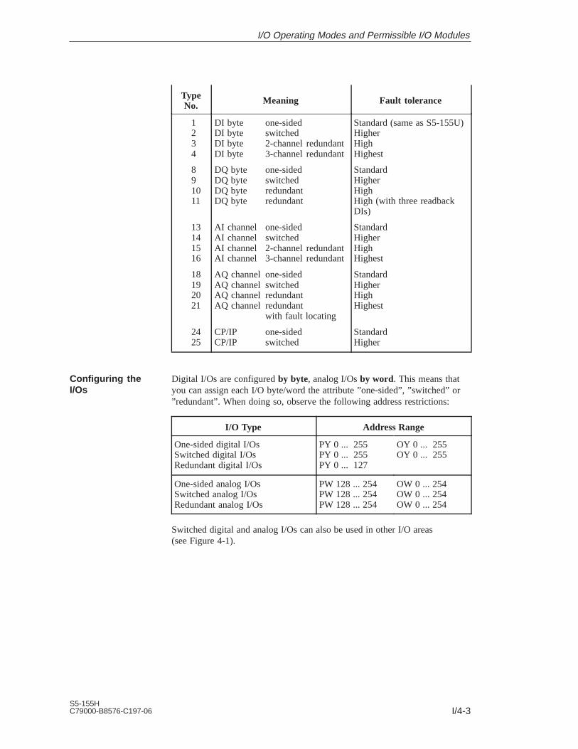
I/4-3S5-155HC79000-B8576-C197-06
TypeNo. Meaning Fault tolerance
1234
891011
13141516
18192021
2425
DI byte one-sidedDI byte switchedDI byte 2-channel redundantDI byte 3-channel redundant
DQ byte one-sidedDQ byte switchedDQ byte redundantDQ byte redundant
AI channel one-sidedAI channel switchedAI channel 2-channel redundantAI channel 3-channel redundant
AQ channel one-sidedAQ channel switchedAQ channel redundantAQ channel redundant
with fault locating
CP/IP one-sidedCP/IP switched
Standard (same as S5-155U)HigherHighHighest
StandardHigherHighHigh (with three readbackDIs)
StandardHigherHighHighest
StandardHigherHighHighest
StandardHigher
Digital I/Os are configured by byte, analog I/Os by word. This means thatyou can assign each I/O byte/word the attribute ”one-sided”, ”switched” or”redundant”. When doing so, observe the following address restrictions:
I/O Type Address Range
One-sided digital I/OsSwitched digital I/OsRedundant digital I/Os
PY 0 ... 255PY 0 ... 255PY 0 ... 127
OY 0 ... 255OY 0 ... 255
One-sided analog I/OsSwitched analog I/OsRedundant analog I/Os
PW 128 ... 254PW 128 ... 254PW 128 ... 254
OW 0 ... 254OW 0 ... 254OW 0 ... 254
Switched digital and analog I/Os can also be used in other I/O areas(see Figure 4-1).
Configuring theI/Os
I/O Operating Modes and Permissible I/O Modules

I/4-4S5-155H
C79000-B8576-C197-06
Figure 4-1 provides an overview of the various I/O areas in the S5-155H forredundant, switched and one-sided I/Os.
Reserved for H system (IM314R/IM324R)
Extended I/Os (O I/Os)
Switched I/Os
Switched I/Os
Page areaAccess only via data handling blocks or
page commands(switched or one-sided only)
Hardware registers
F:F000H
F:F080H
F:F100H
F:F200H
F:F300H
F:F400H
F:FC00H
F:FE00H
Switched unassigned I/O address area
Switched digital I/Os
Interprocessor communication flags forswitched I/Os
F:0000H
F:1000H
F:2100H
PY 128...OB 2552- and 3-channelAIs
F:FEFFH Identreg.
F:FFFFH
PY 0...PY 127
F:FD00HIM3
IM4
P area
O area
Redundant and one-sidedswitched analog I/Os orswitched one-sideddigital I/Os
Redundant and one-sided digital I/Os
Figure 4-1 I/O Areas in the S5-155H
I/O Address Areas
I/O Operating Modes and Permissible I/O Modules

I/4-5S5-155HC79000-B8576-C197-06
The process output image (redundant PIQ, switched PIQ, one-sided PIQ) isoutput after OB 1 has been processed. The S5-155H self-test then runs. Thiscan last between 2 and 38 ms (test slice 2 ms * n), plus any time needed forinterrupt servicing.
The process input image (redundant PII, switched PII, one-sided PII) is thenread in. The PIIs of both subunits are exchanged and compared. OB 1 is thenre-invoked (see Figure 2-2).
Updating theProcess Input andOutput Images
I/O Operating Modes and Permissible I/O Modules

I/4-6S5-155H
C79000-B8576-C197-06
4.2 Redundant I/Os (Overview)
In this mode, the input or output module has the same address in bothsubunits.
This mode offers the highest possible degree of fault tolerance, since failureof a central controller or an input or output module is tolerated (NON-STOPoperation). The modules can be plugged into either the central controller orthe expansion unit.
Figure 4-2 shows a redundant (two-channel) configuration.
zwei -kanalig
Two-channel
Subunit A Subunit B
I/O
EU x EU x
CPU948R
324R
CPU948R I/O Two-
channel
IM
IM I
M
IM
IM
I/O Two-channel
CPU948R
304
CPU948R I/O Two-
channel
IM
IM I
M
IM
IM
Figure 4-2 Redundant I/O Operation and Permissible Modules
In two-channel redundant I/O mode, the same interface modules andexpansion units can be used as for the S5-155U (refer to the S5-135U/155USystem Manual).
If the ET electronic terminator is being used in a redundant configuration, thefollowing applies: If an ET 100 I/O byte must be passivated due to a timeout(QVZ), then the whole phase of this ET 100 is shut down.
”Redundant I/O” means the redundant input/output module in question isplugged into subunit A and subunit B, and both I/O modules have the sameI/O address and have been configured with COM 155H as redundant.
Redundant I/O(1-out-of-2)
Interface Modulesand ExpansionUnits
Digital and AnalogI/O Modules
I/O Operating Modes and Permissible I/O Modules

I/4-7S5-155HC79000-B8576-C197-06
All I/O modules which can be used in the S5-155U can also be used in theS5-155H.
Redundant I/O modules are permitted in the following I/O address areas only(see Section 4.1):
Redundant DIs/DQs: FF000 to FF07F (PY 0 to 127)
Redundant AIs/AQs: FF080 to FF1FF (PW 128 to 254 and OW 0 to 254)
Please refer also to the configuring information for I/O modules inSection 4.1.
Note
If you want to operate specific redundant digital inputs or outputs as”NON-STOP DIs” or ”NON-STOP DQs”, please read the informationpresented below in ”Locating facility (LF)”.
For every redundant digital input and every redundant digital output youwant to operate as a NON-STOP DI or NON-STOP DQ, you must configurea special locating facility with which the 155H system program can locateerrors quickly (see Figures 4-8/4-9).
”NON-STOP DI/DQ” means that the failure of the DI/DQ and its subsequentrepair have no effect whatsoever on the process.
A locating facility (LF) for a NON-STOP DI or a NON-STOP DQ consists of
a locating digital input (L-DI) and
a locating digital output (L-DQ).
This section presents an overview in the form of keywords of thecharacteristics of the various redundant I/O types in the S5-155H.
Redundant DIs without error locating
– Error detection: By discrepancy monitoring and edge changemonitoring
– Error locating: None
– Passivation: Passivation of the DI byte in the subunit in which a’stuck at 0’ error was found
Redundant DIs with error locating
– Error detection: By discrepancy monitoring
– Error locating: By L-DQ
– Passivation: Passivation of the defective DI byte
Redundant three-channel DIs
– Error locating: By the 2-out-of-3 method
I/Os
Locating F acility(LF)
Overview ofRedundant I/OTypes
I/O Operating Modes and Permissible I/O Modules

I/4-8S5-155H
C79000-B8576-C197-06
Redundant DQs without error locating
In the case of ’stuck at 1’ errors:
– Error detection: By cyclic comparison of PIQs and readback DIs
– Error locating: None
– Passivation: Passivation of the readback DI; that is, testing of 0 to 1edge no longer possible
In the case of ’stuck at 0’ errors:
– Error detection:– Error location: By testing a 0 to 1 edge change
– Passivation: Passivation of the defective DQ byte
Redundant DQs with error locating
In the case of ’stuck at 1’ errors:
– Error detection: By cyclic comparison of PIQs and readback DIs
– Error locating: By switching off the power supply to the group viaL-DQ
– Passivation: Passivation of the defective DQ byte and all otherredundant DQs with the same group supply
In the case of ’stuck at 0’ errors:
– Error detection:– Error locating:
By testing a 0 to 1 edge change or, at thelatest, after approx. 10 hours when initialstate = ”1”.
– Passivation: None
The defective DQ byte is reported only; access operations are notaffected, and there is no further testing of the DQ byte.
Redundant AIs
– Error detection: By analog value discrepancy monitoring; minimum ormaximum value may be selected on error.
– Error locating:– Passivation: Error-dependent; see Section 4.4
Redundant three-channel AIs
– Error detection:– Error locating:– Passivation:
By analog value discrepancy monitoring
Redundant AQs
– Error detection:– Error locating:– Passivation:
By reading back the analog output value
Note:More detailed information on all of the I/O types listed above, and in thesame order, can be found in Sections 4.3 and 4.4.
I/O Operating Modes and Permissible I/O Modules

I/4-9S5-155HC79000-B8576-C197-06
The table below tells you the amount of time needed to detect an error ondigital output types 10 and 11.
ErrorType 10
with Readback DIType 11
with 3 Readback DIs
1. ’Stuck at 1’ on DQ module.When PIQ intermittent.
After two 0 1 edge changes After two 0 1 edge changes
2. ’Stuck at 1’ on DQ module.When PIQ = 0.
After TI at latest After TI at latest
3. ’Stuck at 1’ on DQ module.When process image = 1.
Through inspection Immediately preceding the L-DQtest = every 10 hours
4. ’Stuck at 0’ on DQ module orwirebreak in DQ moduleconnection.When PIQ intermittent.
After two 0 1 edge changes or *) in L-DQ test = every 10 hours (fault hasshort-term effect1) on process)
After two 0 1 edge changes or *) immediately preceding theL-DQ test = every 10 hours
5. ’Stuck at 0’ on DQ moduleor wirebreak in DQ moduleconnection. When PIQ = 0.
Through inspection Through inspection
6. ’Stuck at 0’ on DQ moduleor wirebreak in DQ moduleconnection. When PIQ = 1.
In the L-DQ test (= every 10hours) (fault has short-term 1)
effect on process)
Immediately preceding the L-DQtest = every 10 hours
7. ’Stuck at 1’ after decoupling diode(fault cannot be automaticallyrectified).When process image = 0.
After TI at latest After TI at latest
8. ’Stuck at 1’ after decoupling diode(fault cannot be automaticallyrectified).When process image = 1.
Through inspection Through inspection
9. Wirebreak in or after the decouplingdiode.When PIQ intermittent.
After two 0 1 edge changes or *) immediately after the L-DQtest = every 10 hours (fault hasshort-term1) effect on the process)
After two 0 1 edge changes or*) immediately following L-DQtest = every 10 hours (fault hasshort-term1) effect on the process)
10. Wirebreak in or after decouplingdiode. When process image = 0.
Through inspection Through inspection
11. Wirebreak in or after decouplingdiode (the wires must be redundantup to the actuator and must be runfrom the actuator to the readbackDI). When process image = 1.
In the L-DQ test = every 10 hours(fault has short-term 1) effect onthe process)
In the L-DQ test = every 10 hours(fault has short-term 1) effect onthe process)
12. Short-circuit to 0 after decouplingdiode (fault cannot be automaticallyreported, but can be located).When PIQ = 1.
After TI at latest After TI at latest
TI = 2 * TR or 2 * PLC scan time (whichever is higher)
*) Depending on which event occurs first1) Short-term effect on the process
(’short-term’ means 1 * tR + 2 * basic clock rate for timed interrupts,without regard to the PLC scan time)
TR = Configured readback delay timetR = Actual readback delay time
Detecting Errorson Digital OutputModules
I/O Operating Modes and Permissible I/O Modules

I/4-10S5-155H
C79000-B8576-C197-06
4.3 Redundant Digital Inputs/Outputs (DIs/DQs)
4.3.1 Redundant DIs without Error Locating Facility
Two-channel (1-of-2) DIs without error locating facility detect faults, but donot locate them. This means that these DIs cannot be operated as”NON-STOP” DIs.
There is a redundant digital input in both subunit A and subunit B. Thesystem program compares these DIs cyclically to make sure that their signalstates are identical; this comparison is made during updating of the PII. If thesystem program discovers redundant DIs with different signal states, theseDIs are flagged and the configured discrepancy timer started. As long as thetimer is running, the last identical value is maintained as signal state.
If the signal states of the DIs are still different after the discrepancy time hasexpired, an appropriate entry is made in the error DB, and the systemprogram waits for the next edge change. Until this edge change takes place,the last identical value continues to be retained as signal state. After the edgechange, the signal state of the DI on which the edge change took placebecomes the final valid signal state. The other side is passivated.
The signal states of the redundant DIs are also compared in cases of directI/O access. In the event of a discrepancy, the last identical value is taken assignal state.
0 .. 70 .. 7
Reference potential
Subunit B
L-
+24 V
Redundant DI
Subunit A
Redundant DI
220 V AC
0 ... 7
SENSORS
DI(e. g. 430)
DI(e. g. 430)
Figure 4-3 Redundant Two-Channel DIs without Error Locating Facility
I/O Operating Modes and Permissible I/O Modules
I/4-11S5-155HC79000-B8576-C197-06
4.3.2 Redundant DIs with Error Locating Facility
The 1-out-of-2 DI with LF both detects and locates faults. With the aid of thecircuitry shown in Figure 4-4, the system locates the defective DI module inthe event of a fault. The following sequence is then put into effect when thediscrepancy time has elapsed: A ”0” signal is output to both L-DQs (subunits A and B), thus switching
off the sensor power supply. A ”0” must be read back from both DIs after the specified readback delay
time has elapsed. A ”1” at a DI indicates a defect in the module. A ”1” signal is output to both L-DQs.
The defective module is reported and the DI byte passivated; that is, thissubunit’s DI byte will no longer be accessed (one-sided operation). Faultlocation can take several PLC cycles, depending on the configured readbackdelay time. During this time, the last valid process I/O image is transferred inthe case of direct access to the relevant DI bytes. ”Relevant” DI bytes are allDI bytes sharing the same group power supply.
The term ”group” designates all sensors for redundant DIs or DQs suppliedby the same L-DQ. The smallest possible group consists of one redundantbyte, the largest possible group of all redundant DIs in an S5-155H.
The L-DIs of the two-channel 1-out-of-2 are tested for ’stuck at 0’ and ’QVZ’(timeout) once in each test cycle (approx. every 5 minutes).
The L-DIs and L-DQs of the two-channel 1-out-of-2 DIs are tested for’stuck at 0’ every 10 hours by setting the L-DQs to 0 page by page. They aretested for ’stuck at 1’ only in the master’s Restart routine by setting theL-DQs to 0 in both subunits. Also refer back to the table entitled ”DetectingErrors on Digital Output Modules”.
Testing the ErrorLocating Facility
I/O Operating Modes and Permissible I/O Modules

I/4-12S5-155H
C79000-B8576-C197-06
Subunit A
DI
L-DQ
DI
One-channelsensor
Group supply(min. 8 sensors)
Sensor supply
L+
L-DQ for error locating increases availability by passivating thedefective DI via software. This protective circuit is necessary forDI-NON-STOP-operation.
L+
L-DI
L-DQ
L-DI
Subunit B
Figure 4-4 Block Diagram: 1-out-of-2 DI with Error Locating
0...7
L- DI
220 V AC
Subunit B
L-
+24 VRed. DI
X.0
Subunit A
DI (e. g. 430)
DI(e. g. 430)
L- DQ
DQ (e. g. 454)
L+ Q
L+
L- DQ
DQ (e. g. 454)
L+ Q
L- DI Red. DI
DI (e. g. 430)
DI (e. g. 430)
L+
0...7
L-DQ : Locating DQL-DI : Locating DIRed. DI : Redundant DI
Note: A relay must be used when other sensors are to be supplied via an L-DQ.
SENSORS
X.7
Figure 4-5 Redundant Two-Channel DI with Error Locating
I/O Operating Modes and Permissible I/O Modules

I/4-13S5-155HC79000-B8576-C197-06
4.3.3 Redundant Three-Channel DIs
Three-channel (1-out-of-3) DIs detect and locate faults. This means that theseDIs can be operated as ”NON-STOP DIs”.
Each subunit is equipped with one redundant digital input, and the third isassigned to switched I/Os or to subunit A or B. Assigning the third DI to theswitched I/Os provides a higher degree of fault tolerance than assigning it tosubunit A or B.
The 155H system program compares the three DIs cyclically to make surethat their signal states are identical. This comparison takes place duringupdating of the process input image. If the system program discovers DIswith different signal states, these DIs are flagged and the specifieddiscrepancy timer started. As long as this timer is running, the relevantstandard value is taken as signal state, depending on whether one or threesensors were configured. If only one sensor was configured, the standardvalue is based on a 2-out-of-3 decision. If three sensors were configured, thelast identical value is retained as signal state.
If the signal states of the DIs are still different after the discrepancy time haselapsed, the fault is reported. The result of the 2-out-of-3 decision is given asvalid signal state. The byte is passivated. The DI continues on a 1-out-of-2basis until the fault has been eliminated and the byte depassivated.
Third channelswitched or insubunit A orsubunit B
SENSORS
0 ... 7 0 .. 7 0 .. 7
DI(e. g. 430)
Reference potential
Subunit B
L -
+24 VRedundant DI
Subunit A
Redundant DI
220 V AC
0 ... 7
DI(e. g. 430)
DI(e. g. 430)
Figure 4-6 Redundant Three-Channel DI with One Sensor
I/O Operating Modes and Permissible I/O Modules

I/4-14S5-155H
C79000-B8576-C197-06
S7’’S0’’S7’S0’S0 S7
Third channelswitched or insubunit A orsubunit B
Reference potential
Subunit B
L -
+24 V
Redundant DI
Subunit A
Redundant DI
220 V AC
0 .. 7
DI(e. g. 430)
0 .. 7
DI(e. g. 430)
0 .. 7
DI(e. g. 430)
Figure 4-7 Redundant Three-Channel DI with Three Sensors
Direct I/O access to a three-channel DI is permitted.
The standardized value of the three digital inputs is supplied as the result.
The use of three sensors provides the highest possible degree of faulttolerance, as sensor faults can also be detected, located and passivated.
The maximum amount of time needed to locate a fault is:
2 x configured discrepancy time +
2 x PLC scan time.
I/O Operating Modes and Permissible I/O Modules

I/4-15S5-155HC79000-B8576-C197-06
4.3.4 Configuring Redundant Process Interrupts (DI 0)
1. Configure DI 0 as a redundant digital input without error locating (andwire accordingly).
The system program uses the time configured for DI 0.0 as thediscrepancy time for all DI 0 bits. Times specified for DI 0.1 to DI 0.7 areirrelevant.
The maximum discrepancy time configurable for DI 0 is 1.0 s.
2. Enter ”Interrupt DI”: YES in COM 155H’s operating system form.
3. Specify ”Process interrupts:”YES and ”Timed interrupt servicing”:YES indata block DX 0. Specify 10 ms as ”Basic clock rate for timed interruptservicing”.
Only the master subunit has access to DI 0. The standby subunit checks itselfand the master every 10 ms for a ’stuck at 0’ or ’stuck at 1’ error.
If a ’stuck at 0’ or ’stuck at 1’ error triggers an edge on the DI, the interruptOB is invoked as a result. An additional DI byte wired to DI 0 will allow theuser to detect the ’wrong’ edge change.
The ’correct’ edge on a properly functioning DI always results in invocationof an interrupt OB. The system program thus ensures that no interrupts willbe lost due to ’stuck at 0/1’ errors.
If a ’stuck at 0’ or ’stuck at 1’ error occurs in the master subunit, the systemprogram initiates a standby-master transfer as soon as the discrepancy timehas elapsed. The fault is reported, the defective DI 0 passivated, and the’AGF’ bit (PLC fault) set in the H flag word (see Section 8.5). Thus the DI 0in the other subunit is used to detect all process interrupts.
If a ’stuck at 0’ or ’stuck at 1’ error occurs in the standby subunit, the fault isreported, the defective DI 0 passivated and the ’AGF’ bit set in the H flagword as soon as the discrepancy time has elapsed.
Wire DI 0 as a redundant DI without error locating. Even without errorlocating, ’stuck at 0’ and ’stuck at 1’ errors will be located (see above).Unused inputs must be connected to ground. The two redundant DI 0 shouldbe plugged in the two central controllers.
If a QVZ (timeout) occurs in the master subunit, the system program carriesout a standby-master transfer. The QVZ is reported, the defective DI 0 isreported as “2-way switched defective” and the DI 0 of the new master isused for the interrupt detection.
Functions,Principle ofOperation andError Handling
Wiring DI 0
I/O Operating Modes and Permissible I/O Modules

I/4-16S5-155H
C79000-B8576-C197-06
4.3.5 Redundant DQs without Error Locating Facility (LF)
Two-channel (1-out-of-2) DQs without error locating facility can only detecterrors/faults, but cannot locate them, or only to a limited degree. The systemtreats this type of DQ as follows:
Reading back of the digital output values, taking into consideration theconfigured readback delay time. This makes it possible to detect, but notlocate, ’stuck at 1’ errors.
’Stuck at 0’ errors are detected only after the next edge change from 0 to 1:
First, a ”1” signal is output in one subunit (subunit A, for instance) whilea ”0” signal continues to be output in subunit B.
After the configured readback delay has elapsed, the readback must showa ”1” signal. If it does not, the error is located and reported.
This DQ test is executed alternately in the other subunit on every edgechange from 0 to 1.
Note:When configuring with COM 155H, you must enter the DQ readback delaytime, since the different digital output modules have different signalpropagation times.
Red. DI
DI (e. g. 430)
+24 V
0...7
220V AC
Referencepotential
––
220V AC
+24 V
0...70...7
Subunit BSubunit A
DQ (e. g. 451)
L+ Q
Red. DQ
0...7
Red. DQ : Redundant DQRea. DI : Readback DI
Q
DQ (e. g. 451)
L+ Q
Red. DQ
Q
L–
Load
Redundant DQ Power supply may also be a load voltage.
Result: When the load voltage fails, the whole redundant DQ groupfails
Figure 4-8 Two-Channel Redundant DQ without Error Locating
I/O Operating Modes and Permissible I/O Modules

I/4-17S5-155HC79000-B8576-C197-06
4.3.6 Redundant DQs with Error Locating Facility (DQ Type 10)
Two-channel DQs (1-out-of-2) for intermittent (frequently switched) outputscan both detect and locate faults/errors. In the event of a ’stuck at 1’ signal, aDQ of this type is passivated/isolated by the L-DQ in its controller (subunit),which outputs ”0” (shut down). In the case of a ’stuck at 0’ signal, the error isreported only. This means that this digital output can be operated asNON-STOP DQ (Figure 4-8).
The system program treats this type of DQ as follows:
Reading back of the digital output values, taking into account theconfigured readback delay time. This makes it possible to detect’stuck at 1’ errors and to localize them by shutting down the group powersupply.
’Stuck at 0’ errors cannot be detected until the after the next edge changefrom 0 to 1:
First, a ”1” signal is output in one of the subunits (subunit A, for instance)while subunit B continues to output a ”0” signal.
The readback value must be ”1” as soon as the readback delay time haselapsed. Otherwise, the error is located and reported.
This DQ test is executed alternately in the other subunit on each edgechange from 0 to 1.
No further DQ tests are performed on the relevant DQ byte in the event of a’stuck at 0’ error, nor is the L-DQ tested for ’stuck at 1’. In order to enhancethe fault tolerance, the byte is not passivated, and can continue to beaccessed.
In the case of ’stuck at 1’ errors, the bad DQ byte and the associatedreadback DI are passivated. The relevant DQ byte is no longer accessed. Thegroup power supply is shut down via the L-DQ, which passivates allredundant DQs connected to this group supply (one-sided operation).
A ’stuck at 0’ error for an initial status of ”1” (during execution of the ”L-DQfor DQ test”) is detected a maximum of Ttest times following the firstpossible readback of the ’stuck at 0’ error and the L-DQ test aborted.
Ttest is a maximum of 3 * the basic clock rate for timed interrupts. In order toensure that an error of this type affects the actuator for as brief a time aspossible, the basic clock rate for timed interrupts in DX 0 should be set to1 * 10 ms.
When type 10 DQs are used, an error of this kind affects the actuator for amaximum period of Ttest.
The L-DIs and L-DQs of the two-channel 1-out-of-2 DIs are tested once pertest cycle (approx. every 5 minutes) for ’stuck at 0’ and ’QVZ’ (timeout).
The L-DQs of the two-channel 1-out-of-2 DQs may and must be set to zeropage by page only. ’Stuck at 1’ errors are detected every 10 hours by settingone L-DQ at a time to zero on a page-by-page basis.
155H SystemProgram Response
Testing the ErrorLocating Facility
I/O Operating Modes and Permissible I/O Modules
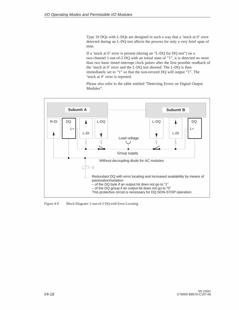
I/4-18S5-155H
C79000-B8576-C197-06
Type 10 DQs with L-DQs are designed in such a way that a ’stuck at 0’ errordetected during an L-DQ test affects the process for only a very brief span oftime.
If a ’stuck at 0’ error is present (during an ”L-DQ for DQ test”) on atwo-channel 1-out-of-2 DQ with an initial state of ”1”, it is detected no morethan two basic timed interrupt clock pulses after the first possible readback ofthe ’stuck at 0’ error and the L-DQ test aborted. The L-DQ is thenimmediately set to ”1” so that the non-errored DQ will output ”1”. The’stuck at 0’ error is reported.
Please also refer to the table entitled ”Detecting Errors on Digital OutputModules”.
Subunit A Subunit B
DQ L-DQ L-DQ DQ
Group supply
Load voltage
Redundant DQ with error locating and increased availability by means ofpassivation/isolation– of the DQ byte if an output bit does not go to “1”– of the DQ group if an output bit does not go to “0”This protective circuit is necessary for DQ NON-STOP operation.
L+ L+
R-DI
Without decoupling diode for AC modules
L-DI L-DI
Figure 4-9 Block Diagram: 1-out-of-2 DQ with Error Locating
I/O Operating Modes and Permissible I/O Modules

I/4-19S5-155HC79000-B8576-C197-06
220V AC
L+
L+
0..7
Subunit BSubunit A
L - DQ L - DI Red. DQ
L-DQ : Locating DQL-DI : Locating DIRed. DQ : Redundant DQR-DI : Readback DI
Q
Referencepotential
––
220V AC
+24 V+24 V
L–
Load0...7
DQ(e. g. 451)
L+
L+
DI(e. g. 430)
DQ(e. g. 451)
QL+
L - DI
L+
DI(e. g. 430)
0..7
Red. DQ
DQ(e. g. 451)
R-DI
DI(e. g. 430)
0..7
A load power supply may also be used.Result: If the load supply fails, the entire redundant DQ group fails
L - DQ
Q QQ Q
DQ(e. g. 451)
Figure 4-10 Two-Channel Redundant DQs with Error Locating Facility (Type 10)
I/O Operating Modes and Permissible I/O Modules

I/4-20S5-155H
C79000-B8576-C197-06
4.3.7 Redundant DQ with Error Locating Facility and 3 Readback DIs (DQ Type 11)
The two-channel (1-out-of-2) DQ for non-intermittent (infrequentlyswitched) outputs detects and locates errors. The system program handles thistype of DQ as follows:
Readback of the digital output values, taking into account the configuredreadback delay time. This makes it possible to detect ’stuck at 1’ errors,and then to locate them by shutting down the group power supply.
’Stuck at 0’ errors are not detected until after the next edge change from0 to 1:
First, a ”1” signal is output in one subunit, (subunit A, for instance) whilea ”0” signal continues to be output in the other subunit (subunit B in thiscase).
The readback value must be ”1” once the configured readback delay timehas elapsed. Otherwise, the error is located and reported.
This DQ test is executed alternately in the other subunit on each edgechange from 0 to 1.
In addition, with the aid of the R-DIs in subunits A and B, the DQ istested for ’stuck at 0’ errors every 10 hours and 5 minutes after eachpassivation. This makes it possible to detect a ’stuck at 0’ error in the DQmodule even without an edge change.
A locating facility must be configured for type 11 (Figure 4-9). This circuit isrequired to allow NON-STOP operation of a non-intermittent DQ.
If a ’stuck at 0’ error is present (during execution of the ”L-DQ for DQ test”)on a DQ module with an initial state of ”1”, it is detected prior to executionof the L-DQ test and the L-DQ test is suppressed. The ’stuck at 0’ error isreported.
If, in the case of initial state ”1”, a ’stuck at 0’ error is present in or after thedecoupling diode (during execution of the ”L-DQ for DQ test”), it is detectedno more than Ttest after the first possible readback of the ’stuck at 0’ errorand the L-DQ test aborted.
Ttest is a maximum of 3 * the basic clock rate for timed interrupts. In orderthat an error of this kind affect the actuator as briefly as possible, the basicclock rate for timed interrupt should be set to 1 * 10 ms in DX 0.
No further DQ tests are performed on the relevant DQ byte in the case of a’stuck at 0’ error. To increase fault tolerance, the byte is not passivated andwill continue to be accessed.
The bad DQ byte is passivated in the case of ’stuck at 1’ errors. The byte isno longer accessed. The group power supply is shut down via the L-DQ, thuspassivating all redundant DQs connected to this group supply (one-sidedoperation).
I/O Type 11
155H SystemProgram Response
I/O Operating Modes and Permissible I/O Modules

I/4-21S5-155HC79000-B8576-C197-06
The L-DIs and L-DQs of two-channel 1-out-of-2 DIs are tested once per testcycle (approx. every 5 minutes) for ’stuck at 0’ and ’QVZ’ (timeout).
The L-DQs of two-channel 1-out-of-2 DQs may and must be set to zero pageby page only. ’Stuck at 1’ errors are detected every 10 hours by setting oneL-DQ at a time to zero page by page.
If, when the initial state is ”1”, a ’stuck at 0’ error is present in the DQmodule (during the ”L-DQ for DQ” test), it is detected prior to execution ofthe L-DQ test and the test suppressed. The ’stuck at 0’ error is reported.
If, in the case of an initial state of ”1”, a ’stuck at 0’ error is present in orafter the decoupling diode (during execution of the ”L-DQ for DQ test”),the error is detected no more than two timed interrupt basic clock pulses afterthe first possible readback of the ’stuck at 0’ error and the L-DQ test aborted.The L-DQ being tested is then immediately set to ”1” in order to reduce theduration of the effect on the process to a minimum. The ’stuck at 0’ error isreported. (Also refer to the table entitled ”Detecting Errors on Digital OutputModules”).
Subunit A Subunit B
DQ L-DQ L-DQ DQ
Group supply
Load voltage
Redundant DQ with error locating and increased availability by means of passivation:– of the DQ byte if an output bit does not go to “1”– of the DQ group if an output bit does not go to “0”This protective circuit is necessary for DQ NON-STOP-operation of a non-intermittent DQ.
L+ L+
R-DI
Decoupling diodes
R-DIR-DI
L-DI L-DI
Figure 4-11 Block Diagram: 1-out-of-2 DQ with Error Locating for Non-Intermittent Signals
Testing the ErrorLocating Facility
I/O Operating Modes and Permissible I/O Modules

I/4-22S5-155H
C79000-B8576-C197-06
DQ(e. g. 451)
0..7 0..7
L+
L+
0..7
Subunit BSubunit A
L - DQ L - DI Red.DQ
L-DQ : Locating DQL-DI : Locating DI
Q
220V ACReferencepotential
––
220V AC
+24 V+24 V
L–
Load
0...7
L+
L+
DI(e. g. 430)
DQ(e. g. 451)
Q
DQ(e. g. 451)
L+
L - DI
L+
0..7
R-DI
0..7
A load voltage supply may also be used.Result: If the load voltage fails, the entire redundant DQ group fails
L - DQ
Q QQ Q
DI(...)
Subunit Baddr. areaP or OR-DI
DI(...)
Subunit Aaddr. areaP or O
Red.DQ
Red. DQ : Redundant DQR-DI : Readback DI
Subunit Aor B orswitchedaddr. areaP or OR-DI
DI(e. g. 430)
DQ(e. g. 451)
DI(e. g. 430)
Figure 4-12 Redundant Non-Intermittent DQ with Error Locating Facility (Type 11)
I/O Operating Modes and Permissible I/O Modules

I/4-23S5-155HC79000-B8576-C197-06
4.4 Redundant Analog Input/Outputs (AIs/AQs)
The ”L PY” operation for redundant analog inputs is not permitted, andresults in a Transfer error (TLAF). Redundant analog current inputs areprovided only for 4-wire measuring transducers.
Direct I/O access to redundant analog inputs with the STEP 5 operation“L PW” supplies a standardized value as the result. Depending on theconfiguration (min./max.) this is the lower or higher non-linearized value.
4.4.1 Principle of the Redundant 1-out-of-2 Analog Inputs
500
Subunit A Subunit B
AI (460/465)
One-channelanalog sensor:Voltage0 to 10 V or–10 V to +10 V
AI (460/465)
AI
One-channelanalog sensor:20 mAunidirectionalor bidirectionalcurrent
AI
0.1 %
20 mA corresponds to 10 V
Figure 4-13 Redundant 1-out-of-2 AI, One-Channel with One or Two Sensors
Direct I/O Access
I/O Operating Modes and Permissible I/O Modules

I/4-24S5-155H
C79000-B8576-C197-06
Subunit A Subunit B
AI (460/465)
Two-channelanalog sensor:Voltage0 to 10 V or–10 V to +10 V
AI (460/465)
AI (460/465)
Two-channelanalog sensor:20 mAunidirectionalor bidirectionalcurrent
AI (460/465)
Figure 4-14 Redundant 1-out-of-2 AI, Two-Channel with One or Two Sensors
I/O Operating Modes and Permissible I/O Modules

I/4-25S5-155HC79000-B8576-C197-06
4.4.2 Redundant AI 463: FB 32
The two-channel (1-out-of-2) analog inputs (AI) detect errors, but do notalways locate them.
Function block FB 32 ”2-AE:463” is provided expressly for the purpose ofreading in analog values. It is part of the COM 155H package, and is on thediskette in program file S5CR70ST.S5D. All other required parameters, suchas discrepancy value, discrepancy time and upper and lower limit valuesmust be configured with COM 155H.
FB 32 can be used for AI module 463. It reads in the first two analog valuesand replaces the non-linearized values. Even if errors occur simultaneously,only one AI is passivated; one AI continues to work in the case of an error.
The input and output parameters for the function block are identical to thoseof FB 32: ”2:AE:463” for the S5-155U. In contrast, the test for rangeviolations in modules which are configured in COM 155H as redundant takesinto account the specified upper and lower range limits (refer to the tablewith configuration aids for COM 155H).
Note
An FB call to a non-existent and unconfigured module causes the addressingerror ADF. If ADF is not acknowledged with OB 25, the standby CPU goesinto STOP.
The execution times for the ”H” function block FB 33 are higher than thosefor standard function blocks by approx. 750 s owing to the redundantfunction.
Function block FB 32 reads analog value XE from two analog value inputsand, based on its nominal range, provides a proportional output value XAwithin the specifiable range limits UGR (lower limit) and OGR (upper limit).The analog value can be read in by the cyclic sampling method. The FBnumber may be changed during loading.
STEP 5 program Graphic representation FB 32
: JU FB 32NAME : 2-AE:463BG : 2-AE:463KNKD :
2 AE:463BG : XA
OGR :BG : XAKNKD: FBUGR : KNKD: FBOGR BUXA : OGR : BU
FB :OG UUGR :
BU :UGR :
Execution Time for”Function Blocks”
Calling the FB for2-ChannelRedundant AIs(FB 32)
I/O Operating Modes and Permissible I/O Modules

I/4-26S5-155H
C79000-B8576-C197-06
Description of input and output parameters
Name ParameterType
DataType
Description Remarks
BG D KY I/O area and module address In I/O area P:KY = 0.128 to 248 (4 channels) In I/O area O:KY = 1.0 to 248
KNKD D KY Channel number and channel typeKY = x, yx = 0 to 3 channel numbery = 20 to 21 channel type
20 unipolar (range 0 to + 1024)fixed-value representation
21 unipolar (range 256 to 1280)fixed-value representation
OGR D KG Upper limit of the output value – 1701411 + 39 to + 1701412 + 39
UGR D KG Lower limit of the output value – 1701412 + 39 to + 1701411 + 39
XA 1) Q D Output value as floating-pointnumber
Nominal output value
FB Q BI Error bit 0 = no error1 = fewer than 192 units (for KD = 21) are read.
BU Q BI Range violation 0 = no range violation1 = range violation– if the bit ”Ü” has signal state ”1” (overflow)
in the read analog value– if the nominal range is exceeded (dependent
on the parameter KD)
1) If a data (double) word is used as the output value XA, the relevant data block must be opened before the FB 32 is called.
Note
Channel type 21 must only be selected if the measuring range 4–20 mA isset on the module in the limits 256 to 1280.
Parameter Type Data Type Permissible Actual Operands
I, Q BI for an operand with bit address I, Q, F
D for an operand with doubleword address ID, QD, FD, DD
I/O Operating Modes and Permissible I/O Modules

I/4-27S5-155HC79000-B8576-C197-06
Range violation BU
In the case of modules which were configured as one-channel modules, aviolation of the nominal analog value range is reported in BU. If the analogvalue is within the overflow range (analog value > +2047 units), the outputvalue XA is limited to +2047 units. If the analog value lies below zero, theFB bit is set and XA displays the current value.
In the case of redundant modules, the upper and lower limit valuesconfigured with COM 155H are used to check for range violations. If theselimit values are exceeded by the preferred value, the BU bit is set. When theoverflow bit (BU) is set, the current value is also displayed at XA.
If the limit values configured in COM 155H lie outside the nominal rangeand if no discrepancy time violation occurred, the BU bit is set if the nominalrange is exceeded (the preferred value is exceeded) and XA is limited to thenominal range limits.
If processing is performed correctly, the result of logic operation is set to ”0”on exiting the function block and accumulator 1 contains the value 0. Theoutput XA contains the scaled value. The parameters FB and BU have thesignal state ”0”.
If a value is specified in a parameter which does not lie within the definedvalue range, the function block reports this parameter assignment error withthe RLO ”1” and with an error number in accumulator 1. The output XA isthen assigned zero. The parameters FB and BU have the signal state ”0”.
Error number KF = 1: Parameter BG 128 in P-I/O area
2: Parameter KN 3
3: Sum of parameter BG and twice parameter KN 255, uneven BG addresses
4: Parameter KD not 20 or 21
5: Parameter OGR = parameter UGR
6: 1. parameter BG 1
If a module that does not exist or a channel that does not exist and is also notconfigured is selected, this causes an addressing error (ADF).
In one-sided operation, if the overflow bit BU is set, the nominal range limitvalue is output at output XA and the accumulator 1 contains the value 0.
Notes on RangeViolation (BU) Bits
Error Handling
I/O Operating Modes and Permissible I/O Modules

I/4-28S5-155H
C79000-B8576-C197-06
Both analog values are checked for discrepancies. The permissiblediscrepancy value is calculated by adding a relative value (a percentage ofthe maximum value of the two analog values) to an absolute value (in unitscorresponding to the analog value’s notation):
Dperm. = ABS +REL x RAWV(max)
100
Dperm.: Permissible analog value discrepancy
ABS: Absolute component of the configured discrepancy
REL: Relative component of the configured discrepancy
RAWV(max): The higher of the two instantaneous analog values
The following was configured with COM 155H:
ABS: 70
REL: 10%
Preferred value: Max.
Actual analog value subunit A: 1000
Actual analog value subunit B: 980
Actual discrepancy: D = 1000 – 980 = 20
100Permissible discrepancy Dperm. = 70 +
10 x 1000= 170
It follows that the actual discrepancy lies within the permissible range. Foradditional calculations, the value 1000 will be used for XE.
When FB 32 is called, the analog values are read in from the two subunits,exchanged, and standardized. If a one-sided, locatable error (wirebreak ortimeout) occurs, this AI is passivated; that is, it will no longer be accessedand the error is reported. The other AI continues to work in one-sidedoperation.
If the 155H system program detects a discrepancy error, it checks one of thesubunits for an overflow or range-violated condition. If it finds one, this AI ispassivated and the error reported. Otherwise, the standby controller’s AI ispassivated when the specified discrepancy time has elapsed.
Simultaneous occurence of an overflow or range violation on both AIs and adiscrepancy leads to the standby being passivated.
Discrepancy is only recognized in the encoding range of the module to 2047units. From this value onwards, the BU and FB bits are set. If larger analogsignals are applied, the encoded value is no longer defined.
Notes on ErrorDetection
Example
I/O Operating Modes and Permissible I/O Modules

I/4-29S5-155HC79000-B8576-C197-06
If the two modules report different errors, passivation is prioritized asfollows:
1. Timeout (QVZ)
2. Wirebreak
3. Overflow
4. Range violation.
If FB 32: 2-AE:463 detected only a range violation or overflow condition butnot a discrepancy, the standardized preferred value (min. or max.) is passed,together with the ”Range violation” (BU) or ”Overflow” (BU) bit.
Conversion if KD = 20:100% 10V 1024 units, 0% 0V 0 units
Conversion if KD = 21:100% 20mA 1280 units, 0% 4mA 256 units
KD = 20 KD = 21
Value [V] Upper/lower limit value Value[mA]
Upper/lower limit value
1 102 10% 5.6 358 10%
2 205 20% 7.2 461 20%
3 308 30% 8.8 564 30%
4 410 40% 10.4 666 40%
5 512 50% 12 768 50%
6 614 60% 13.6 870 60%
7 717 70% 15.2 973 70%
8 820 80% 16.8 1076 80%
9 922 90% 18.4 1178 90%
10 1024 100% 20 1280 100%
Configuration Aidsin COM 155H
I/O Operating Modes and Permissible I/O Modules

I/4-30S5-155H
C79000-B8576-C197-06
4.4.3 Redundant AI 466: FB 33
The two-channel (1-out-of-2) analog inputs (AI) detect errors, but do notalways locate them.
Function block FB 33 ”2-AE:466” is provided expressly for the purpose ofreading in analog values. It is part of the COM 155H package, and is on thediskette in program file S5CR70ST.S5D. All other required parameters, suchas discrepancy value, discrepancy time and upper and lower limit valuesmust be configured with COM 155H.
FB 33 can be used for module 466. It reads in the first two analog values andreplaces the non-linearized values. Even if errors occur simultaneously, onlyone AI is passivated; one AI continues to work in the case of an error.
The input and output parameters for the function block are identical to thoseof FB 33: ”2:AE:466” for the S5-155U. In contrast, the test for rangeviolations in modules which are configured in COM 155H as redundant takesinto account the specified upper and lower range limits (refer to the tablewith configuration aids for COM 155H).
Note
An FB call to a non-existent and unconfigured module causes the addressingerror ADF. If ADF is not acknowledged with OB 25, the standby CPU goesinto STOP.
The execution times for the ”H” function block FB 33 are higher than thosefor standard function blocks by approx. 750 s owing to the redundantfunction.
Function block FB 33 reads analog value XE from two analog value inputsand, based on its nominal range, provides a proportional output value XAwithin the specifiable range limits UGR (lower limit) and OGR (upper limit).The analog value can be read in by the cyclic sampling method. The FBnumber may be changed during loading.
STEP 5 program Graphic representation FB 33
: JU FB 33NAME : 2-AE:466BG :
2-AE:466KNKD :
2-AE:466BG : XA
OGR :BG : XAKNKD: FB
UGR :KNKD: FBOGR : BU
XA :OGR : BUUGR :
FB :UGR :
BU :
Execution Time for”Function Blocks”
Calling the FB for2-ChannelRedundant AIs(FB 33)
I/O Operating Modes and Permissible I/O Modules

I/4-31S5-155HC79000-B8576-C197-06
Description of input and output parameters
Name ParameterType
DataType
Description Remarks
BG D KY I/O area and module address In I/O area P:KY = 0.128 to 248 (16 channels)In I/O area O:KY = 1.0 to 248
KNKD D KY Channel number and channel typeKY = x, yx = 0 to 15 channel numbery = 22 to 25 channel type
22 Fixed-point representation bipolar(nominal range -2048 to + 2048)
23 Number representation bipolar(nominal range -2048 to +2048)
24 Binary representation unipolar(nominal range -0 to +4095)
25 Fixed-point representation unipolar(nominal range +512 to +2559)
OGR D KG Upper limit of the output value – 1701411 + 39 to + 1701412 + 39
UGR D KG Lower limit of the output value – 1701412 + 39 to + 1701411 + 39
XA 1) Q D Output value as floating-pointnumber
Scaled output value
FB Q BI Error bit 0 = no error1 = fewer than 384 units are read where KD = 25
BU Q BI Range violation 0 = no range violation1 = range violation– if the bit ”Ü” has signal state ”1” (overflow)
in the read analog value– if the nominal range is exceeded (dependent
on the parameter KD)
1) If a data (double) word is used as the output value XA, the relevant data block must be opened before the FB 33 is called.
Parameter Type Data Type Permissible Actual Operands
I, Q BI for an operand with bit address I, Q, F
D for an operand with doubleword address ID, QD, FD, DD
Range violation BU
In the case of modules which were configured as one-channel modules, aviolation of the nominal analog value range is reported in BU as a rangeviolation.
Notes on RangeViolation (BU) Bits
I/O Operating Modes and Permissible I/O Modules

I/4-32S5-155H
C79000-B8576-C197-06
In the case of redundant modules, the upper and lower limit valuesconfigured with COM 155H are used to check for range violations. If theselimit values are exceeded by the preferred value, the BU bit is set. When theoverflow bit (BU) is set, the current value is also displayed at XA.
If the limit values configured in COM 155H lie outside the nominal rangeand if no discrepancy time violation occurred, the BU bit is set if the nominalrange is exceeded (the preferred value is exceeded) and XA is limited to thenominal range limits.
If processing is performed correctly, the result of logic operation is set to ”0”on exiting the function block and accumulator 1 contains the value 0. Theoutput XA contains the scaled value. The parameters FB and BU have thesignal state ”0”.
If a value is specified in a parameter which does not lie within the definedvalue range, the function block reports this parameter assignment error withthe RLO ”1” and with an error number in accumulator 1. The output XA isthen assigned zero. The parameters FB and BU have the signal state ”0”.
Error no. KF = 1: Parameter BG 128 in P-I/O area
2: Parameter KN 15
3: Sum of parameter BG and twice parameter KN 255,uneven BG addresses
4: Parameter KD not 22 or 25
5: Parameter OGR = parameter UGR
6: 1. parameter BG 1
If a module or a channel that does not exists is selected, this causes anaddressing error (ADF).
When the error bit FB is set, the value zero is output at the output XA and theaccumulator 1 contains the value 0.
In one-sided operation, if the overflow bit BU is set, the nominal range limitvalue is output at output XA and the accumulator 1 contains the value 0.
Both analog values are checked for discrepancies. The permissiblediscrepancy value is calculated by adding a relative value (a percentage ofthe maximum value of the two analog values) to an absolute value (in unitscorresponding to the analog value’s notation):
Dperm. = ABS +REL x RAWV(max)
100
Dperm.: Permissible analog value discrepancy
ABS: Absolute component of the configured discrepancy
REL: Relative component of the configured discrepancy
RAWV(max): The higher of the two instantaneous analog values
Error Handling
Notes on ErrorDetection
I/O Operating Modes and Permissible I/O Modules

I/4-33S5-155HC79000-B8576-C197-06
The following was configured with COM 155H:
ABS: 70
REL: 10%
Preferred value: Max.
Actual analog value subunit A: 1000
Actual analog value subunit B: 980
Actual discrepancy: D = 1000 – 980 = 20
100Permissible discrepancy Dperm. = 70 +
10 x 1000= 170
It follows that the actual discrepancy lies within the permissible range. Foradditional calculations, the value 1000 will be used for XE.
When FB 33 is called, the analog values are read in from the two subunits,exchanged, and standardized. If a one-sided, locatable error (wirebreak ortimeout) occurs, this AI is passivated; that is, it will no longer be accessedand the error is reported. The other AI continues to work in one-sidedoperation.
If the 155H system program detects a discrepancy error, it checks one of thesubunits for an overflow or range-violated condition. If it finds one, this AI ispassivated and the error reported. Otherwise, the standby controller’s AI ispassivated when the specified discrepancy time has elapsed.
Simultaneous occurence of an overflow or range violation on both AIs and adiscrepancy leads to the standby being passivated.
Discrepancy is only recognized in the encoding range of the module to +4096units. If larger analog signals are applied, the encoded value is no longerdefined.
If the two modules report different errors, passivation is prioritized asfollows:
1. Timeout (QVZ)
2. Wirebreak
3. Range violation.
If FB 33: 2-AE:466 detected only a range violation or overflow condition butnot a discrepancy, the standardized preferred value (min. or max.) is passed,together with the ”Range violation” (BU) or ”Overflow” (BU) bit.
Example
I/O Operating Modes and Permissible I/O Modules

I/4-34S5-155H
C79000-B8576-C197-06
Conversion if KD = 22:100% 10V 2048 units, 0% 0V 0 units
Conversion if KD = 23:100% 10V 2048 units, 0% 0V 0 units
Conversion if KD = 24:100% 5V 2048 units, 0% 0V 0 units
Conversion if KD = 25:100% 5V 2560 units, 0% 1V 512 units100% 20mA 2560 units, 0% 4mA 512 units
KD = 24 KD = 25
Value [V] Upper/lower limit value Value[mA]
Upper/lower limit value
1 410 20% 5.6 716 10%
2 820 40% 7.2 921 20%
3 1229 60% 8.8 1126 30%
4 1638 80% 10.4 1331 40%
5 2048 100% 12 1536 50%
6 2458 120% 13.6 1740 60%
7 2867 140% 15.2 1945 70%
8 3277 160% 16.8 2150 80%
9 3686 180% 18.4 2355 90%
10 4096 200% 20 2560 100%
KD = 22,23 KD = 25
Value [V] Upper/lower limit value Value [V] Upper/lower limit value
1 205 10% 1.4 716 10%
2 410 20% 1.8 921 20%
3 614 30% 2.2 1126 30%
4 820 40% 2.6 1331 40%
5 1024 50% 3.0 1536 50%
6 1229 60% 3.4 1740 60%
7 1434 70% 3.8 1945 70%
8 1638 80% 4.2 2150 80%
9 1843 90% 4.6 2355 90%
10 2048 100% 5.0 2560 100%
Configuration Aidsin COM 155H
I/O Operating Modes and Permissible I/O Modules

I/4-35S5-155HC79000-B8576-C197-06
4.4.4 Redundant AIs: FB 40
The two-channel (1-out-of-2) analog inputs detect errors, but do not alwayslocate them.
Function block FB 40 ”H-RLG:AE” is provided expressly for the purpose ofreading in analog values. It is part of the COM 155H package, and is on thediskette in program file S5CR70ST.S5D. All other required parameters, suchas discrepancy value and discrepancy time, must be configured withCOM 155H.
FB 40 can be used for modules 460 and 465. It reads in the first two analogvalues and replaces the non-linearized values. If a module reports awirebreak, overflow or range violation, that module is passivated and theerror reported. From that point on, operation is one-sided, using only theother module. The simultaneous occurrence of an overflow and a rangeviolation does not result in passivation.
The input and output parameters for the function block are identical to thoseof FB 40 ”RLG:AE” for the S5-155U. In contrast, the test for rangeviolations in modules which are configured as redundant takes into accountthe specified upper and lower range limits.
Depending on the operations used, the execution times for ”H” functionblocks may be higher than those for standard function blocks:
FB 40 H-RLG:AE, for two-channel redundant AIs,by approx.: 750 s
Function block FB 40 reads analog value XE from two analog value inputsand, based on its nominal range, provides a proportional output value XAwithin the specifiable range limits UGR (lower limit) and OGR (upper limit).The analog value can be read in either by the cyclic or selective samplingmethod. The FB number must not be changed during loading.
STEP 5 program Graphic representation FB 40
: JU FB 40NAME : H-RLG:AEAE :
BG : XABG : BG : XAP/Q : P/Q : FBKNKT :
P/Q : FBKNKT : BU
OGR :KNKT : BUOGR : TBITUGR : OGR : TBIT
EINZ : UGR :XA :
UGR :EINZ :
FB :EINZ :
BU :TBIT :
Execution Time for”Function Blocks”
Calling the FB for2-ChannelRedundant AIs(FB 40)
I/O Operating Modes and Permissible I/O Modules

I/4-36S5-155H
C79000-B8576-C197-06
Description of input and output parameters
NameParam–
eterType
DataType Description Remarks
BG
P/Q
KNKT
OGR
UGR
EINZ
XA
FB
BU
TBIT
D
D
D
D
D
I
Q
Q
Q
Q
KF
KS
KY
KG
KG
BI
D
BI
BI
BI
Module address
I/O area
Channel number KNChannel type KT
Upper limit of the output value
Lower limit of theoutput value
Selective sampling
Address foroutput value XA
Bit address for”Wirebreak” bit
Bit address for”Range violation” bit
Bit address for”Analog input” bit
P/Q = P: BG = 128 to 240P/Q = Q: BG = 0 to 240
P/Q = P: P areaP/Q= Q: O area
KN = 0 to 15KT = 3 to 6 (see Notes)
–1701412+39 to +1701412+39
–1701412+39 to +1701412+39
EINZ = 0: Cyclic sampling
Scaled value betweenUGR and OGR (see Note)
0 = No wirebreak1 = Wirebreak
0 = No range violation1 = Range violated
Always 0
Parameter Type Data Type Permissible Actual Operands
I, Q BI for an operand with bit address I, Q, F
D for an operand with doubleword address ID, QD, FD, DD
The permissible analog input modules can provide the analog value in fourdifferent notations. You must choose the one you want by setting the KTparameter accordingly.
KT = 3 : Absolute value between 4 and 20 mAKT = 4 : Unipolar representationKT = 5 : Bipolar absolute valueKT = 6 : Bipolar fixed-point number
If the KT parameter is set to a value less than 3, the function block uses KT =4; if it is set to a value exceeding 6, the function block uses KT = 6. The KTparameter must be in agreement with the method of representation set on themodule itself.
Notes on ChannelType KT
I/O Operating Modes and Permissible I/O Modules

I/4-37S5-155HC79000-B8576-C197-06
The input value (XE) read in from the analog input module is convertedaccording to the formulas below depending on channel type parameter KT.
OGR : Upper limit value UGR : Lower limit valueXE : Input value XA : Output value
2048
KT = 3 XA =UGR x (2560–XE) + OGR x (XE–512)
2048
KT = 4 XA =
4096
UGR x (2048–XE) + OGR x XE
KT = 5/6 XA =UGR x (2048–XE) + OGR x (XE+2048)
Range limits for the output value
The analog value can be represented as a physical value if suitable rangelimits are selected.
Example:
Analog ValueRange Phys. Value Range Limits Resolution
0 to 10 V 2 to 150 C 2000000+01 1500000+03 0.1 C
Range violation BU
In the case of modules which were configured as one-channel modules, aviolation of the nominal analog value range is reported in BU. If the analogvalue is within the overflow range (analog value > +4096 or < –4096 units),it is limited to +4096 or –4096.
In the case of redundant modules, the upper and lower limit valuesconfigured with COM 155H are used to check for range violations. If theanalog value lies within the overflow range (analog value > +4096 or< –4096), the ”Wirebreak” and ”Range violation” bits are set, and the analogvalue limited to + or – 4096 units.
In the case of channel type 3 (4 to 20 mA), the BU bit is also set for valuesfrom 3 to 4 mA.
In the event of a wirebreak, XA is set to 0.
If FB 40 is called for a channel that is not configured and not plugged, thestandby CPU goes into STOP and the ADF LED on the master CPU lights up(OB 25 is not called).The program that caused the error is displayed in the B stack in the standbyCPU.
Notes on OutputValue XA
Notes onUGR/OGR:
Notes on RangeViolation (BU) Bits
Wirebreak
Addressing Error
I/O Operating Modes and Permissible I/O Modules

I/4-38S5-155H
C79000-B8576-C197-06
Both analog values are checked for discrepancies. The permissiblediscrepancy value is calculated by adding a relative value (a percentage ofthe maximum value of the two analog values) to an absolute value (in unitscorresponding to the analog value’s notation):
Dperm. = ABS +REL x RAWV(max)
100
Dperm.: Permissible analog value discrepancy
ABS: Absolute component of the configured discrepancy
REL: Relative component of the configured discrepancy
RAWV(max): The higher of the two instantaneous analog values
The following was configured with COM 155H:
ABS: 100
REL: 10%
Preferred value: Max.
Actual analog value subunit A: 1000
Actual analog value subunit B: 980
Actual discrepancy: D = 1000 – 980 = 20
100Permissible discrepancy Dperm. = 100 +
10 x 1000= 200
It follows that the actual discrepancy lies within the permissible range. Foradditional calculations, the value 1000 will be used for XE.
When FB 40 is called, the analog values are read in from the two subunits,exchanged, and standardized. If a one-sided, locatable error (timeout,wirebreak) occurs, the module is passivated; that is, it will no longer beaccessed (one-sided operation).
If the 155H system program detects a discrepancy error, it checks one of thesubunits for an overflow or range-violated condition. If it finds one, themodule is passivated. Otherwise, the standby controller’s module ispassivated when the specified discrepancy time has elapsed.
If the two modules report different errors, passivation is prioritized asfollows:
1. Timeout (QVZ)
2. Wirebreak
3. Overflow
4. Range violation.
Notes on ErrorDetection
Example
I/O Operating Modes and Permissible I/O Modules
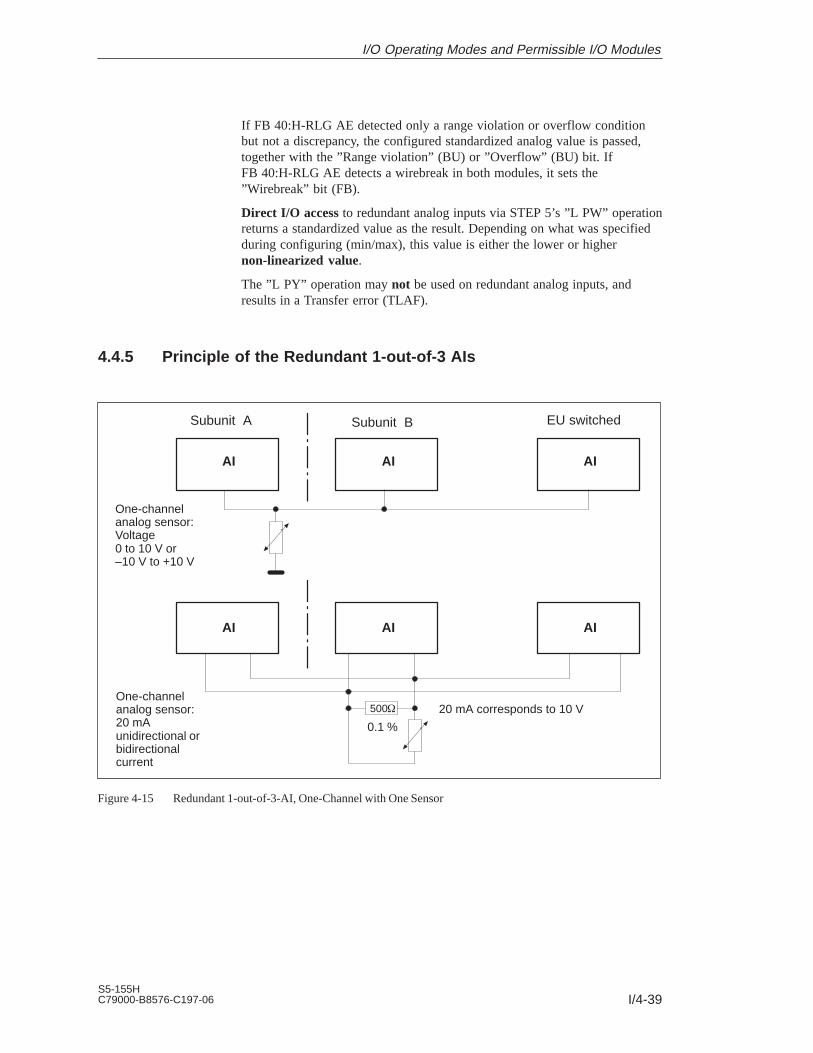
I/4-39S5-155HC79000-B8576-C197-06
If FB 40:H-RLG AE detected only a range violation or overflow conditionbut not a discrepancy, the configured standardized analog value is passed,together with the ”Range violation” (BU) or ”Overflow” (BU) bit. IfFB 40:H-RLG AE detects a wirebreak in both modules, it sets the”Wirebreak” bit (FB).
Direct I/O access to redundant analog inputs via STEP 5’s ”L PW” operationreturns a standardized value as the result. Depending on what was specifiedduring configuring (min/max), this value is either the lower or highernon-linearized value.
The ”L PY” operation may not be used on redundant analog inputs, andresults in a Transfer error (TLAF).
4.4.5 Principle of the Redundant 1-out-of-3 AIs
Subunit BSubunit A EU switched
AI
One-channelanalog sensor:Voltage0 to 10 V or–10 V to +10 V
AI AI
AI AI AI
One-channelanalog sensor:20 mAunidirectional orbidirectionalcurrent
500
0.1 %
20 mA corresponds to 10 V
Figure 4-15 Redundant 1-out-of-3-AI, One-Channel with One Sensor
I/O Operating Modes and Permissible I/O Modules

I/4-40S5-155H
C79000-B8576-C197-06
Three-channelanalog sensor:Voltage0 to 10 V or–10 V to +10 V
Subunit BSubunit A EU switched
Three-channelanalog sensor:20 mAunidirectionalor bidirectionalcurrent
AI AI AI
AI AI AI
Figure 4-16 Redundant 1-out-of-3-AI, Three-Channel with Three Sensors
I/O Operating Modes and Permissible I/O Modules

I/4-41S5-155HC79000-B8576-C197-06
4.4.6 Redundant AI 463: FB 35
The three-channel (2-out-of-3 / 1-out-of-3) analog inputs (AI) always detectand locate errors.
Standard function block FB 35 ”3-AE:463” is provided expressly for thepurpose of reading in three-channel analog values. It is part of the COM155H package, and is on the diskette in program file S5CR70ST.S5D. Allother required parameters, such as discrepancy value, discrepancy time,upper and lower limit value and address of the third channel must beconfigured with COM 155H.
FB 35 can be used for module 463. It reads in the first three analog valuesand replaces the non-linearized values. The value which lies in the middle ofthe three read values serves as the output value XA. The display value is alsotaken as the reference value for calculating discrepancy values. If errorsoccur simultaneously, only two AIs are passivated; one AI continues to workin the case of an error.
The input and output parameters for the function block are identical to thoseof FB 32: ”AE:463” for the S5-155U. In contrast, the test for range violationsin modules which are configured in COM 155H as redundant takes intoaccount the specified upper and lower range limits (refer to the table withconfiguration aids for COM 155H).
Note
An FB call to a non-existent and unconfigured module causes the addressingerror ADF. If ADF is not acknowledged with OB 25, the standby CPU goesinto STOP.
The execution times for the ”H” function block FB 35 are higher than thosefor standard function blocks by approx. 800 s owing to the redundantfunction.
Function block FB 35 reads three analog value XE from three analog valueinputs and, based on its nominal range, provides a proportional output valueXA within the specifiable range limits UGR (lower limit) and OGR (upperlimit). The analog value can be read in by the cyclic sampling method. TheFB number may be changed during loading.
STEP 5 program Graphic representation FB 35: JU FB 35
NAME : 3-AE:4633 AE 463BG : 3-AE:463
BG XAKNKT : BG : XAOGR : KNKT : FBUGR :
KNKT : FBOGR : BU
XA :OGR : BUUGR :
FB :UGR :
BU :
Execution Time for”Function Blocks”
Calling the FB for3-ChannelRedundant AIs
I/O Operating Modes and Permissible I/O Modules

I/4-42S5-155H
C79000-B8576-C197-06
Description of input and output parameters
Name ParameterType
DataType
Description Remarks
BG D KY I/O area and module address In I/O area P:KY = 0.128 to 248 (4 channels)In I/O area O:KY = 1.0 to 248
KNKD D KY Channel number and channel typeKY = x, yx = 0 to 3 channel numbery = 20 to 21 channel type
20 Fixed-point representation unipolar(nominal range 0 to + 1024)
21 Fixed-point representation unipolar(nominal range 256 to 1280)
OGR D KG Upper limit of the output value – 1701411 + 39 to + 1701412 + 39
UGR D KG Lower limit of the output value – 1701412 + 39 to + 1701411 + 39
XA 1) Q D Output value as floating-pointnumber
Scaled output value
FB Q BI Error bit 0 = no error1 = fewer than 192 units (for KD = 21) are read
BU Q BI Range violation 0 = no range violation1 = range violation– if the bit ”Ü” has signal state ”1” (overflow)
in the read analog value– if the nominal range is exceeded (dependent
on the parameter KD)
1) If a data (double) word is used as the output value, the relevant data block must be opened before the FB 35 is called.
Note
Channel type 21 must only be selected if the measuring range 4–20 mA isset on the module in the limits 256 to 1280.
Parameter Type Data Type Permissible Actual Operands
I, Q BI for an operand with bit address I, Q, F
D for an operand with doubleword address ID, QD, FD, DD
I/O Operating Modes and Permissible I/O Modules

I/4-43S5-155HC79000-B8576-C197-06
Range violation BU
As long as no discrepancy value violation occurred, the BU bit is set whenthe nominal range of the ‘middle value’ (not the mean value) is exceeded. Inthe case of three-way redundant modules, the upper and lower limit valuesconfigured with COM 155H are used to check for range violations. If theselimit values are exceeded, the BU bit is set. When the overflow bit (BU) isset, the current value is also displayed at XA.
In the event of a wirebreak of all three channels, XA is set to 0 and the FB bitis set. Only two channels are passivated and the error is reported. The thirdchannel continues to work even with a wirebreak, an error report is made toregister the error.
If processing is performed correctly, the result of logic operation is set to ”0”on exiting the function block and accumulator 1 contains the value 0. Theoutput XA contains the scaled value. The parameters FB and BU have thesignal state ”0”.
If a value is specified in a parameter which does not lie within the definedvalue range, the function block reports this parameter assignment error withthe RLO ”1” and with an error number in accumulator 1. The output XA isthen assigned zero. The parameters FB and BU have the signal state ”0”.
Error no. KF = 1: Parameter BG 128 in P-I/O area
2: Parameter KN 3
3: Sum of parameter BG and twice parameter KN 255uneven BG addresses
4: Parameter KD not 20 or 21
5: Parameter OGR = parameter UGR
6: 1. parameter BG 1
If a module that does not exist or a channel that does not exist and is also notconfigured is selected, this causes an addressing error (ADF).
When the error bit FB is set, the value zero is output at the output XA. Theaccumulator 1 contains the value 0. This only applies if KD = 21 and twochannels are already passivated and a wirebreak occurs at the third channel.
If the overflow bit BU is set, the nominal range limit value is output at outputXA. The RLO is set to signal state ”1”; the accumulator 1 contains the valueread from the module.
Notes on RangeViolation (BU) Bits
Wirebreak
Error Handling
I/O Operating Modes and Permissible I/O Modules

I/4-44S5-155H
C79000-B8576-C197-06
The three analog values are checked for discrepancies. The permissiblediscrepancy value is calculated by adding a relative value (a percentage ofthe maximum value of the two analog values) to an absolute value (in unitscorresponding to the analog value’s notation):
Dperm. = ABS +REL x RAWV(max)
100
Dperm.: Permissible analog value discrepancy
ABS: Absolute component of the configured discrepancy
REL: Relative component of the configured discrepancy
RAWV: The middle of the three instantaneous analog values
The following was configured with COM 155H:
ABS: 70
REL: 10%
Actual analog value subunit A: 1000
Actual analog value subunit B: 980
Actual analog value 3rd channel: 1040
Actual discrepancy: D1 = 1000 – 980 = 20
D2 = 1040 – 1000 = 40
100Permissible discrepancy Dperm. = 70 +
10 x 1000= 170
It follows that the actual discrepancy lies within the permissible range. Foradditional calculations, the value 1000 will be used for XE.
When FB 35 is called, the analog values are read in from the two subunits,exchanged, and the middle of the three analog values is used. If a one-sided,locatable error (timeout, wirebreak) occurs, the module is passivated; that is,it will no longer be accessed (1-out-of-2 operation).
If the 155H system program detects a discrepancy error, it passivates themodule whose analog value shows the largest discrepancy from the other two(2-out-of-3) when the specified discrepancy time has elapsed. If two channelscontinue to work and a discrepancy is found, a check is made to establishwhether a range violation or an overflow occurred in a channel. If so, this AIis passivated and an error is reported. Otherwise, the standby controller’schannel is passivated when the configured discrepancy time has elapsed.
Discrepancy is only recognized in the encoding range of the module to 1024units. From this value onwards, the BU bit is set. If larger analog signals areapplied, the encoded value is no longer defined.
Notes on ErrorDetection
Example
I/O Operating Modes and Permissible I/O Modules

I/4-45S5-155HC79000-B8576-C197-06
If several modules report different errors, passivation is prioritized asfollows:
1. Timeout (QVZ)
2. Wirebreak
3. Overflow
4. Range violation.
If FB 35: ”3-AE:463” detected only a range violation or overflow conditionbut not a discrepancy at two channels, the ”Range violation” (BU) or”Overflow” (BU) bit is set.
Conversion if KD = 20:100% 10V 1024 units, 0% 0V 0 units
Conversion if KD = 21:100% 20mA 1280 units, 0% 4mA 256 units
KD = 20 KD = 21
Value [V] Upper/lower limit value Value[mA]
Upper/lower limit value
1 102 10% 5.6 358 10%
2 205 20% 7.2 461 20%
3 308 30% 8.8 564 30%
4 410 40% 10.4 666 40%
5 512 50% 12 768 50%
6 614 60% 13.6 870 60%
7 717 70% 15.2 973 70%
8 820 80% 16.8 1076 80%
9 922 90% 18.4 1178 90%
10 1024 100% 20 1280 100%
Configuration Aidsin COM 155H
I/O Operating Modes and Permissible I/O Modules

I/4-46S5-155H
C79000-B8576-C197-06
4.4.7 Redundant 3-Channel AI 466: FB 36
The three-channel (2-out-of-3 / 1-out-of-3) analog inputs always detect andlocate errors.
Standard function block FB 36 ”3-AE:466” is provided expressly for thepurpose of reading in three-channel analog values. It is part of the COM155H package, and is on the diskette in program file S5CR70ST.S5D. Allother required parameters, such as discrepancy value, discrepancy time,upper and lower limit value and address of the third channel must beconfigured with COM 155H.
FB 36 can be used for module 466. It reads in the first three analog valuesand replaces the non-linearized values. The value which lies in the middle ofthe three read values serves as the output value XA. The display value is alsotaken as the reference value for calculating discrepancy values. If errorsoccur simultaneously, only two AIs are passivated; one AI continues to workin the case of an error.
The input and output parameters for the function block are identical to thoseof FB 33: ”AE:466” for the S5-155U. In contrast, the test for range violationsin modules which are configured in COM 155H as redundant takes intoaccount the specified upper and lower range limits (refer to the table withconfiguration aids for COM 155H).
Note
An FB call to a non-existent and unconfigured module causes the addressingerror ADF. If ADF is not acknowledged with OB 25, the standby CPU goesinto STOP.
The execution times for the ”H” function block FB 36 are higher than thosefor standard function blocks by approx. 800 s owing to the redundantfunction.
Function block FB 36 reads three analog value XE from three analog valueinputs and, based on its nominal range, provides a proportional output valueXA within the specifiable range limits UGR (lower limit) and OGR (upperlimit). The analog value can be read in by the cyclic sampling method. TheFB number may be changed during loading.
STEP 5 program Graphic representation FB 36: JU FB 36
NAME : 3-AE:4663 AE 466BG : 3-AE:466
KNKT : BG : XAOGR : KNKT : FBUGR :
KNKT : FBOGR : BU
XA :OGR : BUUGR :
FB :UGR :
BU :
Execution Time for”Function Blocks”
Calling the FB for3-ChannelRedundant AIs
I/O Operating Modes and Permissible I/O Modules

I/4-47S5-155HC79000-B8576-C197-06
Description of input and output parameters
Name ParameterType
DataType
Description Remarks
BG D KY I/O area and module address In I/O area P:KY = 0.128 to 248 (16 channels)In I/O area O:KY = 1.0 to 248
KNKD D KY Channel number and channel typeKY = x, yx = 0 to 15 channel numbery = 22 to 25 channel type
22 Fixed-point representation bipolar(nominal range -2048 to + 2048)
23 Number representation bipolar(nominal range -2048 to +2048)
24 Binary representation unipolar(nominal range 0 to +4095)
25 Fixed-point representation unipolar(nominal range +512 to + 2559)
OGR D KG Upper limit of the output value – 1701411 + 39 to + 1701412 + 39
UGR D KG Lower limit of the output value – 1701412 + 39 to + 1701411 + 39
XA 1) Q D Output value as floating-pointnumber
Scaled output value
FB Q BI Error bit 0 = no error1 = fewer than 384 units (for KD = 25) are read
BU Q BI Range violation 0 = no range violation1 = range violation– if the bit ”Ü” has signal state ”1” (overflow)
in the read analog value– if the nominal range is exceeded (dependent
on the parameter KD)
1) If a data (double) word is used as the output value, the relevant data block must be opened before the FB 36 is called.
Parameter Type Data Type Permissible Actual Operands
I, Q BI for an operand with bit address I, Q, F
D for an operand with doubleword address ID, QD, FD, DD
Range violation BU
As long as no discrepancy value violation occurred, the BU bit is set whenthe ‘middle value’ (not the mean value) is exceeded. In the case of three-wayredundant modules, the upper and lower limit values configured with COM155H are used to check for range violations. If these limit values areexceeded, the BU bit is set. When the overflow bit (BU) is set, the currentvalue is also displayed at XA.
Notes on RangeViolation (BU) Bits
I/O Operating Modes and Permissible I/O Modules
I/4-48S5-155H
C79000-B8576-C197-06
In the event of a wirebreak of all three channels, XA is set to 0 and the FB bitis set. Only two channels are passivated and the error is reported. The thirdchannel continues to work even with a wirebreak, an error report is made toregister the error.
If processing is performed correctly, the result of logic operation is set to ”0”on exiting the function block and accumulator 1 contains the value 0. Theoutput XA contains the scaled value. The parameters FB and BU have thesignal state ”0”.
If a value is specified in a parameter which does not lie within the definedvalue range, the function block reports this parameter assignment error withthe RLO ”1” and with an error number in accumulator 1. The output XA isthen assigned zero. The parameters FB and BU have the signal state ”0”.
Error no. KF = 1: Parameter BG 128 in P-I/O area
2: Parameter KN 15
3: Sum of parameter BG and twice parameter KN 255uneven BG addresses
4: Parameter KD not 20 or 21
5: Parameter OGR = parameter UGR
6: 1. parameter BG 1
If a module that does not exist or a channel that does not exist and is also notconfigured is selected, this causes an addressing error (ADF).
When the error bit FB is set, the value zero is output at the output XA. Theaccumulator 1 contains the value 0. This only applies if KD = 25 and twochannels are already passivated and a wirebreak occurs at the third channel.
The three analog values are checked for discrepancies. The permissiblediscrepancy value is calculated by adding a relative value (a percentage ofthe maximum value of the two analog values) to an absolute value (in unitscorresponding to the analog value’s notation):
Dperm. = ABS +REL x RAWV(max)
100
Dperm.: Permissible analog value discrepancy
ABS: Absolute component of the configured discrepancy
REL: Relative component of the configured discrepancy
RAWV: The middle of the three instantaneous analog values
Wirebreak
Error Handling
Notes on ErrorDetection
I/O Operating Modes and Permissible I/O Modules
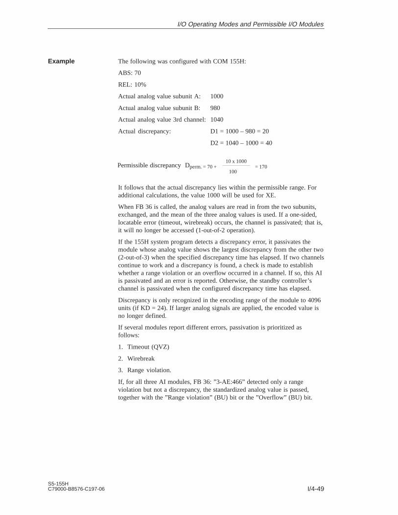
I/4-49S5-155HC79000-B8576-C197-06
The following was configured with COM 155H:
ABS: 70
REL: 10%
Actual analog value subunit A: 1000
Actual analog value subunit B: 980
Actual analog value 3rd channel: 1040
Actual discrepancy: D1 = 1000 – 980 = 20
D2 = 1040 – 1000 = 40
100Permissible discrepancy Dperm. = 70 +
10 x 1000= 170
It follows that the actual discrepancy lies within the permissible range. Foradditional calculations, the value 1000 will be used for XE.
When FB 36 is called, the analog values are read in from the two subunits,exchanged, and the mean of the three analog values is used. If a one-sided,locatable error (timeout, wirebreak) occurs, the channel is passivated; that is,it will no longer be accessed (1-out-of-2 operation).
If the 155H system program detects a discrepancy error, it passivates themodule whose analog value shows the largest discrepancy from the other two(2-out-of-3) when the specified discrepancy time has elapsed. If two channelscontinue to work and a discrepancy is found, a check is made to establishwhether a range violation or an overflow occurred in a channel. If so, this AIis passivated and an error is reported. Otherwise, the standby controller’schannel is passivated when the configured discrepancy time has elapsed.
Discrepancy is only recognized in the encoding range of the module to 4096units (if KD = 24). If larger analog signals are applied, the encoded value isno longer defined.
If several modules report different errors, passivation is prioritized asfollows:
1. Timeout (QVZ)
2. Wirebreak
3. Range violation.
If, for all three AI modules, FB 36: ”3-AE:466” detected only a rangeviolation but not a discrepancy, the standardized analog value is passed,together with the ”Range violation” (BU) bit or the ”Overflow” (BU) bit.
Example
I/O Operating Modes and Permissible I/O Modules

I/4-50S5-155H
C79000-B8576-C197-06
Conversion if KD = 22:100% 10V 2048 units, 0% 0V 0 units
Conversion if KD = 23:100% 10V 2048 units, 0% 0V 0 units
Conversion if KD = 24:100% 5V 2048 units, 0% 0V 0 units
Conversion if KD = 25:100% 5V 2560 units, 0% 1V 512 units100% 20mA 2560 units, 0% 4mA 512 units
KD = 24 KD = 25
Value [V] Upper/lower limit value Value[mA]
Upper/lower limit value
1 410 20% 5.6 716 10%
2 820 40% 7.2 921 20%
3 1229 60% 8.8 1126 30%
4 1638 80% 10.4 1331 40%
5 2048 100% 12 1536 50%
6 2458 120% 13.6 1740 60%
7 2867 140% 15.2 1945 70%
8 3277 160% 16.8 2150 80%
9 3686 180% 18.4 2355 90%
10 4096 200% 20 2560 100%
KD = 22,23 KD = 25
Value [V] Upper/lower limit value Value [V] Upper/lower limit value
1 205 10% 1.4 716 10%
2 410 20% 1.8 921 20%
3 614 30% 2.2 1126 30%
4 820 40% 2.6 1331 40%
5 1024 50% 3.0 1536 50%
6 1229 60% 3.4 1740 60%
7 1434 70% 3.8 1945 70%
8 1638 80% 4.2 2150 80%
9 1843 90% 4.6 2355 90%
10 2048 100% 5.0 2560 100%
Configuration Aidsin COM 155H
I/O Operating Modes and Permissible I/O Modules

I/4-51S5-155HC79000-B8576-C197-06
4.4.8 Three-Channel Redundant AIs: FB 43
Three-channel (3-out-of-1) AIs always detect and locate errors.
Standard function block FB 43 ”3-RLG:AE” is provided for reading inthree-channel analog values. It is part of the COM 155H package, and is onthe diskette in program file S5CR70ST.S5D.
All other required parameters, such as the discrepancy value, the discrepancytime and the address of the third channel, must be configured usingCOM 155H.
The function block can be used for modules 460 and 465. Its input and outputparameters are identical to those of standard FB 40 ”3:RLG:AE” for theS5-155U. The only difference is that the specified upper and lower limitvalues are used to check for range violations on those modules configured asredundant modules.
Depending on the operations used, the execution time of the ”H” functionblocks may be longer than that of the standard function blocks:
FB43: 3-RLG:AE, for three-channel redundant AIs, by approx.: 800 s
Function block FB 43 reads three analog values XE from three analog valueinputs and provides a proportional output value XA, based on its nominalrange, between UGR (lower limit) and OGR (upper limit). The analog valuecan be read in either by the cyclic or selective sampling method. The FBnumber may be changed during loading.
Graphic representation FB 43STEP 5 program
: JU FB 43NAME : 3-RLG:AEBG :P/Q :KNKT :OGR :UGR :EINZ :XA :FB :BU :TBIT :
BG : XA
P/Q : FB
KNKT : BU
OGR : TBIT
UGR :
EINZ :
Execution Time for”Function Blocks”
Calling the FB for3-ChannelRedundant AIs
I/O Operating Modes and Permissible I/O Modules

I/4-52S5-155H
C79000-B8576-C197-06
Description of Input and Output Parameters
Name ParameterType
DataType Description Remarks
BG
P/Q
KNKT
OGR
UGR
EINZ
XA
FB
BU
TBIT
D
D
D
D
D
I
Q
Q
Q
Q
KF
KS
KY
KG
KG
BI
D
BI
BI
BI
Module address
I/O area
Channel number KN,Channel type KT
Upper limit of the output value
Lower limit of the output value
Selective sampling
Address foroutput value XA
Bit address for”Wirebreak” bit
Bit address for”Range violation” bit
Bit address for”Analog input” bit,
P/Q = P: BG = 128 to 240P/Q = Q: BG = 0 to 240P/Q = P: P areaP/Q = Q: O areaKN = 0 to 15KT = 3 to 6 (see Notes)
–1701412+39 to +1701412+39
–1701412+39 to+1701412+39
EINZ = 0: Cyclic sampling
Scaled value betweenUGR and OGR (see Note)
0 = No wirebreak1 = Wirebreak
0 = No range violation1 = Range violated
Always 0
The permissible analog input modules can provide the analog value in fourdifferent notations. You must choose the one you want by setting the KTparameter accordingly.
KT = 3 : Absolute value between 4 and 20 mAKT = 4 : Unipolar representationKT = 5 : Bipolar absolute valueKT = 6 : Bipolar fixed-point number
If the KT parameter is set to a value less than 3, the function block usesKT = 4; if it is set to a value exceeding 6, the function block uses KT = 6.The KT parameter must be in agreement with the method of representationset on the module itself.
Input value XE from the analog input module is converted according to thefollowing formulas, depending on channel type parameter KT.
OGR : Upper limit value UGR : Lower limit value
XE : Input value XA : Output value
KT = 3 XA =UGR x (2560–XE) + OGR x (XE–512)
2048
KT = 4 XA =
4096
UGR x (2048–XE) + OGR x XE
KT = 5/6 XA =UGR x (2048–XE) + OGR x (XE+2048)
2048
Notes on ChannelType KT
Notes on OutputValue XA
I/O Operating Modes and Permissible I/O Modules

I/4-53S5-155HC79000-B8576-C197-06
Range limits for the output value
The analog value can be represented as a physical value if suitable rangelimits are chosen.
Example:
Analog Value Range Phys. Value Range Limits Resolution
0 to 10 V 2 to 150 C 2000000 +01 1500000 +03 0.1 C
Range violation BU
In the case of modules which were configured as three-channel redundantmodules, the upper and lower limit values specified with COM H are used tocheck for range violations. If the analog value from all three modules is inthe overflow range (analog value > +4096 or < –4096 units), the ”Rangeviolation” bit is set and the analog value limited to +4096 or –4096 units.
Channel type 3: 4 to 20 mA The BU bit is also set when the value is in the range from 3 to 4 mA
In the event of a wirebreak on all three modules, XA is set to 0 and the’wirebreak’ bit set.
The three analog values are checked for discrepancies. The permissiblediscrepancy value is calculated from an absolute value (in unitscorresponding to the specified digital notation for the analog value) to whicha relative value (a percentage of the maximum value of the three analogvalues) is added.
Dperm. = ABS +REL x RAWV
100
Dperm.: Permissible analog value discrepancy
ABS: Absolute component of the configured discrepancy
REL: Relative component of the configured discrepancy
RAWV: The middle value of the three current analog values
The following was configured with COM 155H:
ABS: 100 REL: 10%
Actual analog value, subunit A: 1000 subunit B: 980
Actual analog value, 3rd channel: 1040
Actual discrepancy: D1 = 1000 – 980 = 20
D2 = 1040 – 1000 = 40
100Permissible discrepancy Dperm. = 100 +10 x 1000
= 200
Notes onUGR/OGR
Notes on ”RangeViolation” (BU)Bits
Wirebreak
Notes on ErrorDetection
Example
I/O Operating Modes and Permissible I/O Modules

I/4-54S5-155H
C79000-B8576-C197-06
It follows that the actual discrepancy lies within the permissible range.
When FB 43:3-RLG AE is called, it reads the analog values from bothsubunits, exchanges them, and uses the middle value of the three analogvalues. If a one-sided, locatable error occurs (timeout, wirebreak), themodule is passivated; that is, it is no longer accessed (1-out-of-2 operation).
If the 155H system program detects a discrepancy error, the module whoseanalog value differs most from the other two (2-out-of-3) is passivated whenthe configured discrepancy time has elapsed.
If a number of modules report different errors, passivation is prioritized asfollows:
1. Timeout (QVZ)
2. Wirebreak
3. Overflow
4. Range violation.
If FB 43:3-RLG AE detects only a range violation or overflow condition forall three AI modules, but no discrepancy, the standardized analog value ispassed together with the ”Range violation” (BU) or ”Overflow” (BU) bit.
If FB 43:3-RLG AE detects a ”wirebreak” error in all three modules, it setsthe ”Wirebreak” (FB) bit.
I/O Operating Modes and Permissible I/O Modules

I/4-55S5-155HC79000-B8576-C197-06
4.5 Redundant Analog Outputs
All direct access operations (such as T PY, T OY and T OW), to one-sidedanalog outputs are allowed. Output to the I/Os is direct on two channels.
The following applies to AQs: If a STEP 5 operation (T PW, T OW) is usedto output a value to a redundant channel, then the value is output to bothsubunits.
If error detection with error locating is required, you can make this possibleby:
1. Implementing your own readback analog inputs
Note: When analog modules are used, the BASP signal is ignored; that is, thelast analog value is retained. Remember this when wiring the redundantanalog outputs.
2. Selecting the AQ type 21 which is supported by the operating system.
4.5.1 Redundant 2-Channel AQs without Error Locating Facility
The analog output (I/O type 20) has the same address in subunits A and B.No other switched or one-sided DQ or AQ may be configured under thisaddress.
4.5.2 Redundant 2-Channel AQs with Error Locating Facility
The analog output (I/O type 21) has the same address in subunits A and B.All AQ channels are assumed to be intermittent, as no artificial value rangetest is executed. An active side change (relay switching every 10 hours)shows whether or not the passive AQ channel is still intact.
One-Sided AnalogOutputs
Redundant AnalogOutputs
I/O Operating Modes and Permissible I/O Modules

I/4-56S5-155H
C79000-B8576-C197-06
Two-channel analog output modules may be used as NON-STOP AQs whenthe process is able to tolerate an AQ error output at regular intervals, whichnecessitates one or more FB call intervals. In the event of an error – on oneside – the output to the actuator is switched, and the error thus controlled(Figure 4-13). A system with two-channel AQ will tolerate the followingerrors in one of the subunits:
AQ module failure
Failure of the rack power supply
Failure of the load voltage in the event of redundant load voltage
The maximum duration (TF) of an error output can be calculated as follows:
TF = TD + TL–DQ + TQ
TQ Call interval for FB 41 (H:RLG:AA)
TD Configured discrepancy time =AQ output delay + AI readback delay(rounded off to 10 ms units)
TL-DQ Relay delay time of the L-DQ
All direct two-address and four-address I/O access operations (such as T PWand TBGD) to two-channel AQs are permitted. When such an operation isexecuted, the operating system outputs the value to the two-channel AQ inboth subunits. The readback AI is not checked. Address access operations,such as T PY, to two-channel AQs of type 21 are not permitted.
When a subunit fails, the operating system executes the switchover ordecoupling routine, switching all L-DQ relay outputs in the intact subunit to”1” (see Figures 4-13 and 4-14).
Depassivation must be initiated following repairs to a two-channel AQ.When depassivation has been completed, the two-channel AQ is once againfault tolerant.
The setting of the voltage range for AQ and R-AI must match for voltageoutput.
For current output, the R-AI module must be set to 1 V (1.25 V for the 466).
Only two’s complement number representation may be used for the setting.
Fault Toleranceand NON-STOPOperation
Direct I/O Access
Subunit Failure
I/O Operating Modes and Permissible I/O Modules

I/4-57S5-155HC79000-B8576-C197-06
AQ(e.g. 451)
DQ(e.g. 458)
DQ(e.g. 458)
10V 10V
Analogactuator
Non-isolated or isolated
220V AC
L+
L+
Subunit BSubunit A
L - DQ Red. AQ
L-DQ : Locating DQRed. AQ : Redundant AQR-AI : Readback AI
Q
220V AC
+24 V+24 V
L+Q
L+
Red. AQ
AQ(e.g. 451)
R-AI
AI(e.g. 466)
Use of a load voltage supply is also permitted. However, if the loadvoltage fails, the entire redundant AQ group fails.
L - DQ
(Voltage:unidirectionalorbidirectional)
Figure 4-17 Redundant (1-out-of-2) AQs with Error Locating on Voltage Output (I/O Type 21)
I/O Operating Modes and Permissible I/O Modules

I/4-58S5-155H
C79000-B8576-C197-06
1)
AQ(e.g. 470)
DQ(e.g. 458)
L+
20mA/4 to 20 mA
Analogactuator
Non-isolated or isolated
L+
L+
Subunit BSubunit A
L - DQ Red. AQ
Q
+24 V
Load voltage
L+Q
Red. AQ
AQ(e.g. 470)
R-AI
AI(e.g. 466)
L - DQ
(Current:Unidirectional)
DQ(e.g. 458)
+20mA/4 to 20 mA
1) 50 , 0.1 %Setting for the AI module to 1 V. If the 466 module is used as the readback AI, 1.25 V should be set.
Figure 4-18 Redundant (1-out-of-2) AQs with Error Locating on Current Output (I/O Type 21)
At the current input, the module type 6ES5 465-... is not permitted for the R-AI. With an ET 200, 20 mA bi-directional is possible.
I/O Operating Modes and Permissible I/O Modules

I/4-59S5-155HC79000-B8576-C197-06
4.5.3 FB for 2-Channel Redundant AQs (FB 41)
Standard function block FB 41 ”H-RLG:AA” is provided as the means tooutput two-channel analog values. FB 41 is part of the COM 155H package.The FB number may be changed on loading.
The function block converts an input value XE into an output value for ananalog module on the basis of nominal range limits UGR and OGR. An erroris reported in the event of a range violation. The function block alsoprocesses the system’s response to the failure of a two-channel AQcomponent. Special configuring data must be entered with COM 155H forredundant AQs.
The execution time of the ”H” function block may exceed that of thestandard function block, depending on the operations used:
FB 41 H-RLG:AA, for two-channel redundant AQs by approx.: 750 s
FB 41 does the following:
Both subunits still functioning properly
FB 41 reads the readback AI and compares the value read with thecorresponding value in the PIQ. If the discrepancy time elapses, the L-DQrelay is switched and and H error (”Passivation”) reported.
The output value is output to the AQ module in both subunits and thenon-linearized value stored in the PIQ.
One I/O side has failed (CPU in redundant mode)
FB 41 reads the readback AI and compares the value read with thecorresponding value in the PIQ. If the discrepancy time elapses, an Herror (”Error”) is reported. The readback AI is passivated.
The output value is output to the AQ module and the non-linearized valuestored in the PIQ.
One subunit is operating in Solo mode
The output value is output to the AQ module and the non-linearized valuestored in the PIQ. The readback AI is not read.
A) The channel to which the L-DQ bit is assigned must be the AQ for whichFB 41 is called most often, so that the test switchover can run as quickly aspossible. For example;
OB xx 10 msSEGMENT 1 00000000 : L SW xx0001 : T PW 128 Direct access = without error detection0002 : L SW xy0003 : T PW 130 Direct access = without error detection(Direct accesses are used to optimize the run time and for compatibility)....
Execution Time of”Function Blocks”
Using FB 41
Rules for the UserProgram
I/O Operating Modes and Permissible I/O Modules

I/4-60S5-155H
C79000-B8576-C197-06
The output channels must be updated by the FB 41 (even if less often), asonly the FB 41 executes the L-DQ switching, error detection and errorlocalization.
OB 11 10 msSEGMENT 1 00000000 : JU FB 410001 NAME : H-RLG AA0002 XE : FD 10 Input value XE (floating point)0003 BG : KF + 128 Base address of the two-channel AQ0004 P/Q : KS P Area ID: P0005KNKT : KY 0,0 Channel 0...
OB 13 100 msSEGMENT 1 00000000 : JU FB 410001 NAME : H-RLG AA0002 XE : FD 20 Input value XE (floating point)0003 BG : KF + 128 Base address of the two-channel AQ0004 P/Q : KS P Area ID: P0005KNKT : KY 1,0 Channel 1...
The parameter value «Indic. no. of updates (1...10)» is calculated from thenumber of direct access operations and FB 41 calls for the chosen channelper readback delay time.
If the value calculated is greater than 10, an AI module type should bechosen which encodes quicker (for example, 463 or 466).
B) To reduce the switchover surge on the analog output when a subunit failsto a minimum time, the given instruction sequence in OB 1 and OB 37 mustbe implemented : (with x= H flag word)
OB 1SEGMENT 1 00000000 : A F x.1 Redundant mode0001 : S S 100.0 Any flag to signal failure of partner...
I/O Operating Modes and Permissible I/O Modules
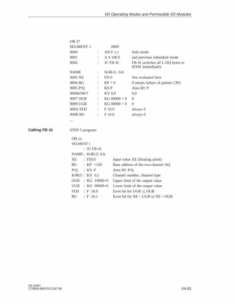
I/4-61S5-155HC79000-B8576-C197-06
OB 37SEGMENT 1 00000000 : AN F x.1 Solo mode0001 : A S 100.0 and previous redundant mode0002 : JC FB 41 FB 41 switches all L-DQ bytes to
0FFH immediatelyNAME : H-RLG: AA0003 XE : FD 0 Not evaluated here0004 BG : KF + 0 0 means failure of partner CPU0005 P/Q : KS P Area ID: P0006KNKT : KY 0,0 0,00007 OGR : KG 00000 + 0 00009 UGR : KG 00000 + 0 0000A FEH : F 10.0 always 0000B BU : F 10.0 always 0...
STEP 5 program:
OB xxSEGMENT 1
: JU FB 41NAME : H-RLG AAXE : FD10 Input value XE (floating point)BG : KF +128 Base address of the two-channel AQP/Q : KS P Area ID: P/QKNKT : KY 0,1 Channel number, channel typeOGR : KG 10000+0 Upper limit of the output valueUGR : KG 00000+0 Lower limit of the output valueFEH : F 16.0 Error bit for UGR OGRBU : F 16.1 Error bit for XE < UGR or XE > OGR
Calling FB 41
I/O Operating Modes and Permissible I/O Modules
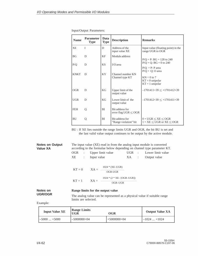
I/4-62S5-155H
C79000-B8576-C197-06
Input/Output Parameters:
Name ParameterType
DataType Description Remarks
XE
BG
P/Q
KNKT
OGR
UGR
FEH
BU
I
D
D
D
D
D
Q
Q
D
KF
KS
KY
KG
KG
BI
BI
Address of theinput value XE
Module address
I/O area
Channel number KNChannel type KT
Upper limit of theoutput value
Lower limit of theoutput value
Bit address forerror flag UGR OGR
Bit address for”Range violation” bit
Input value (floating point) in therange UGR to OGR
P/Q = P: BG = 128 to 240P/Q = Q: BG = 0 to 240
P/Q = P: P areaP/Q = Q: O area
KN = 0 to 7KT = 0 unipolarKT = 1 unipolar
–1701411+39 +1701412+39
–1701412+39 +1701411+39
0 = UGR XE OGR1 = XE UGR or XE OGR
BU : If XE lies outside the range limits UGR and OGR, the bit BU is set and the last valid value output continues to be output by the active module.
The input value (XE) read in from the analog input module is convertedaccording to the formulae below depending on channel type parameter KT.OGR : Upper limit value UGR : Lower limit valueXE : Input value XA : Output value
KT = 0 XA =1024 * (XE–UGR)
OGR-UGR
KT = 1 XA =1024 * (2 * XE– [OGR–UGR])
OGR–UGR
Range limits for the output value
The analog value can be represented as a physical value if suitable rangelimits are selected.
Example:
Input Value XE Range LimitsUGR OGR Output Value XA
–5000 ... +5000 –5000000+04 +5000000+04 –1024 ... +1024
Notes on OutputValue XA
Notes onUGR/OGR
I/O Operating Modes and Permissible I/O Modules

I/4-63S5-155HC79000-B8576-C197-06
4.6 One-Sided I/Os
A one-sided module is always assigned to one of the two subunits. If thissubunit fails, the modules assigned to it also fail. This means that thisconfiguration provides no greater fault tolerance than the S5-155U.
The modules can be plugged into either the central controller or an expansionunit.
When using one-sided I/Os, it is of no significance which subunit is master.Both subunits receive the current signal states. If a timeout (QVZ) occurs ona one-sided I/O, the relevant I/O byte is passivated.
Figure 4-15 shows the various one-sided configurations.
Note:If a subunit fails, the one-sided I/Os in that subunit can no longer carry outtheir assigned functions.
Subunit A Subunit B
EU x
CPU948R
CPU948R
CPU948R
CPU948R I
M
IM
IM
IM
IM
IM
IM
IM
IM
IM
I/OCP
One-sided
324R
304
I/OCP
One-sided
I/OCP
One-sided
Figure 4-19 One-Sided I/O Operation and Permissible Modules
The same interface modules and expansion units can be used for one-sidedoperation in the S5-155H as can be used in the S5-155U (refer to theS5-135U/155U System Manual, Chapter 4).
Configuration andFunctionality
Interface Modulesand ExpansionUnits (EUs)
I/O Operating Modes and Permissible I/O Modules

I/4-64S5-155H
C79000-B8576-C197-06
All I/O modules used in the S5-155U can be used for one-sided operation.
One-sided I/O modules should be used only for subprocesses whose failurecan be tolerated in the event of a controller failure. The software forcontrolling these subprocesses should be implemented in blocks reserved forthis purpose, and these blocks invoked conditionally; that is, only when therelevant subunit is running (see example). If this recommendation is notobserved, a subunit failure will cause a continuous timeout (QVZ error),seriously affecting the scan time.
Sample program: One-sided I/Os assigned to subunit A
STL Explanation
:O F X.1:
:O F X.4::JC FB Subproc.A
Flag for ”PLC in redundant mode”Bit 2 1 in H flag word (high-order byte)
Flag for ”Central controller issubunit”A”, bit 2 4 in H flag word (high-orderbyte)
The subprocess runs only when subunit A is running.
Proceed in the same manner as in the sample program above for one-sidedI/Os assigned to subunit B.
Sample program: One-sided I/Os assigned to subunit B
STL Explanation
:O F X.1::ON F X.4::JC FB Subproc.B
One-sided DIs or DQs may be assigned a given address once only, either insubunit A or subunit B, and the addresses used for one-sided DIs or DQs maynot be used for switched or redundant DIs/DQs.
The same applies to AIs and AQs; that is, these modules may also beassigned a given address once only, and the addresses assigned to AIs/AQsmay not be used for switched or redundant DIs/AIs or DQs/AQs. A one-sidedthird channel on a three-channel DI or AI, however, may be assigned thesame address in the other subunit.
Address area: One-sided DIs: 0FF000h to 0FF1FFhOne-sided DQs: 0FF000h to 0FF1FFhOne-sided AIs/AQs: 0FF080h to 0FF1FFh
All direct I/O access operations (e.g. T PY, T OY, T PW) are permitted forone-sided analog inputs/outputs.
The standard FBs of the S5-155U can be used for one-sided analog I/Os.
Digital and AnalogInput/OutputModules
Addressing
Standard FBs
I/O Operating Modes and Permissible I/O Modules

I/4-65S5-155HC79000-B8576-C197-06
4.7 Switched I/Os
The input or output module can be operated by either subunit. This providesenhanced fault tolerance compared to the S5-155U.
At least one 185U expansion unit is required to operate switched I/Os. Theexpansion unit is connected to both S5-155H central controllers via theIM 304/IM 314R interface modules. Up to 16 switched EUs can be operatedin one S5-155H controller.
When a timeout (QVZ) occurs for a switched I/O, the byte is not passivated.On the first timeout for a switched I/O in redundant controller mode, astandby-master switchover is carried out and the ”PLC fault” bit in the H flagword set.
Note
When a timeout (QVZ) occurs for digital/analog I/Os, the cycle is extendedby approx. 1 ms per byte.
Figure 4-20 illustrates the various switched I/O configurations.
IM
IM
304
Subunit A Subunit B
EU x
CPU948R
324R
CPU948R
304
304
EU 183U, EU 184U, EU 187UEU 185U, ET 100U
CPU948R
304
CPU948R
304
304
304
314R
314R
I/O CPIP
SwitchedI/Os
IM
IM
ET 200
Figure 4-20 Switched I/Os and Permissible Modules
Configuration andFunctionality
I/O Operating Modes and Permissible I/O Modules

I/4-66S5-155H
C79000-B8576-C197-06
At least one 185U expansion unit and the IM 304 to IM 314R interfacemodules are required to operate switched I/Os.
Note
If the IM 300 or IM 308 interface module is plugged into slot 163 in theexpansion unit, the 183U, 184U and 187U or 185U and the ET 100U canalso be operated.
In switched I/O configurations and a maximum ET 100U configuration, atime loop longer than the ET 100U configuration run (max. 4 s) must beprogrammed in OB 22 in both the master and standby controller.
All I/O modules which can be used in the S5-155U can also be used inswitched I/O configurations.
Address area: Switched DIs/DQs: 0FF000h to 0FF1FFh0FF300h to 0FF3FFh0FFC00h to 0FFDFFh
Switched AIs/AQs: 0FF080h to 0FF1FFh0FF300h to 0FF3FFh0FFC00h to 0FFDFFh
All direct I/O access operations (T PY, T OY, and T PW, for example) arepermitted for use with switched analog inputs/outputs.
The standard FBs of the S5-155U can be used for switched I/Os.
Interface Modulesand ExpansionUnits (EUs)
Digital and AnalogI/O Modules
Standard FBs
I/O Operating Modes and Permissible I/O Modules

I/4-67S5-155HC79000-B8576-C197-06
4.8 Hybrid I/O Configurations
All three I/O modes (one-sided, switched and redundant) can be combined inone S5-155H.
The figure below shows possible hybrid configurations.
One-sided: I/O, CP2-channel: I/O
Subunit A Subunit B
EU
CPU948R
CPU948R
CPU948R
CPU948R 3
04
IM
IM
IM
IM
IM
IM
304
IM
IM
One-sided:I/O, CP2-channelI/O
304
324R
One-sided:I/O, CP2-channelI/O
One-sided: I/O, CP2-channel: I/O
EU
IM
EU 185
I/OCPIP
Switched314R
314R
Figure 4-21 Hybrid I/O Configurations
I/O Operating Modes and Permissible I/O Modules

I/4-68S5-155H
C79000-B8576-C197-06
4.9 FB 192 (IM308C-R) for Redundant and One-Sided Operation
4.9.1 General
The standard function block FB 192 with the name IM308C-R is used forredundant and one-sided operation of the S5-155H programmable controllerwith the IM 308-C. The FB 192 IM308C-R is called in the cyclic program forthe programmable controller.
For switched operation of the S5-155H programmable controller, the existingfunction block (FB 192 from the U system) can be used.
The function block can be used in the following address areas:
F F000 to F F1FF
F F400 to F F5FF
F F600 to F F7FF
F F800 to F F9FF (default setting)
F FA00 to F FBFF
F FC00 to F FDFF
F FE00 to F FFFF
The terms ”IM area” and ”IM I/O area” are used in this manual. These referto the above address areas.
The FB 192 IM308C-R runs on the CPU 948R and CPU 948RL in theS5-155H.
Master and slave diagnostics with the FB 192 IM308C-R are only possiblefrom version 3.0 of the IM 308C.
The standard function block is supplied together with a programmingexample which shows how it can be used. With an indirect configuration theparameters for the parameter assignment DB must be specified.
The files are supplied on a 31/2” disk for the operating system S5-DOS/ST(MS-DOS).
The following overview shows which files are supplied:
File Name Valid for... In ProgrammableController
S5ET70ST.S5D CPU 948R / 948RL S5-155H
Areas ofApplication
Form of Supply
I/O Operating Modes and Permissible I/O Modules

I/4-69S5-155HC79000-B8576-C197-06
4.9.2 Standard Function Block FB 192
The standard function block FB 192 with the name IM308C-R is availablefor communication with the IM 308-C via the IM I/O area for the S5-155Hprogrammable controller in redundant and one-sided operation. The standardfunction block executes the following functions:
Function Block Function Call Normally in...
FB 192 Read master diagnosticsRead slave diagnostics
...the cyclic programprocessing level
The standard function block can also be stored in an EPROM submodule.The user can change the number of the standard function block.
The diagnostic data read are structured as described in the “Distributed I/OSystem ET 200” manual.
The standard function block IM308C-R reads the diagnostic data from themaster and the slave from the page number 128.
The following pages from the IM areas are used:
IM Page No. Area on theIM 308C
Data Remark
Page 128 IM4 Page for consistentdiagnostic data
Only read by FB
Page 254 IM3 Interrupt page Read and written by FB
The following STEP 5 memory areas are permitted: data blocks DB andextended data blocks DX.
If no interface module is located in the address area in which the FB 192IM308C-R wants to address the IM 308-C module, this is not recognized bythe function block (exception QVZ).
In FB 192 IM308C-R the programmable controller interrupt processing isdisabled and enabled again if necessary.
The IM 308-C and the standard function block exchange their data via a pagein the IM3 or IM4 area of the interface module. The data exchange mustadhere to a specified access coordination so that the data can be readconsistently (i.e. together). The access coordination to be adhered to isdescribed below. The maximum wait time in the function block is set to1 ms.
Coordinating access between the standard function block and the IM 308-C isachieved via access to the interrupt page.
Overview
FunctionalDescription
AccessCoordination inthe S5-155H
I/O Operating Modes and Permissible I/O Modules

I/4-70S5-155H
C79000-B8576-C197-06
The procedure is explained here based on subunit A:
1. Switch the subunits to S5-155U mode.
2. Query whether subunit A
– Yes, continue with 3.
– No, continue with 6.
3. In subunit A: interface to the interrupt pageIRINFO of the CPU and write interrupt ID to the page
4. In subunit A: interface to the diagnostics page
5. In subunit A: read diagnostics data
6. Copy the data from subunit A to subunit B Receive data from subunit A
7. Switch the subunits to redundant mode again.
The FB 192 IM308C-R is called to read the diagnostic data in the cycle oralternatively in a time-driven program.
Block call:ÁÁÁÁÁÁÁÁÁÁÁÁÁÁÁÁÁÁ
ÁÁÁÁÁÁ
ÁÁÁÁÁÁÁÁÁÁÁÁÁÁÁÁÁÁÁÁÁÁ
ÁÁÁÁÁÁÁÁÁÁÁÁÁ
ÁÁÁÁÁÁÁÁÁSTL representation ÁÁÁ
ÁÁÁÁÁÁÁÁÁÁÁÁÁÁÁÁÁÁÁÁÁÁÁÁÁ
LAD representation ÁÁÁÁÁÁÁÁÁÁÁÁÁ
ÁÁÁÁÁÁÁÁÁ:JU FB 192 ÁÁÁ
ÁÁÁÁÁÁÁÁÁÁÁÁÁÁÁÁÁÁÁÁÁÁÁÁÁ
FB 192 ÁÁÁÁÁÁÁÁÁÁÁÁÁNAME :IM308C-R ÁÁÁÁÁÁÁÁÁÁÁÁÁÁIM308C-R ÁÁÁÁÁÁÁÁÁÁÁ
ÁÁÁÁÁÁÁÁÁDPAD :ÁÁÁÁÁÁ
ÁÁÁÁÁÁÁÁÁÁÁÁÁÁÁÁÁÁÁÁÁÁDPAD
ÁÁÁÁÁÁÁÁÁÁÁÁÁ
ÁÁÁÁÁÁÁÁÁIMST :
ÁÁÁÁÁÁ
ÁÁÁÁÁÁÁÁÁÁÁÁÁÁÁÁÁÁÁÁÁÁ
IMST ERRÁÁÁÁ
ÁÁÁÁÁÁÁÁÁÁÁÁÁÁÁÁÁÁ
FCT :ÁÁÁÁÁÁ
ÁÁÁÁÁÁÁÁÁÁÁÁÁÁÁÁÁÁÁÁÁÁ
FCTÁÁÁÁÁÁÁÁÁÁÁÁÁ
ÁÁÁÁÁÁÁÁÁT-AG : ÁÁÁ
ÁÁÁÁÁÁÁÁÁÁÁÁÁÁÁÁÁÁÁÁÁÁÁÁÁ
T-AG ÁÁÁÁÁÁÁÁÁÁÁÁÁ
ÁÁÁÁÁÁÁÁÁTYP : ÁÁÁ
ÁÁÁÁÁÁÁÁÁÁÁÁÁÁÁÁÁÁÁÁÁÁÁÁÁ
TYP ÁÁÁÁÁÁÁÁÁÁÁÁÁ
ÁÁÁÁÁÁÁÁÁSTAD : ÁÁÁ
ÁÁÁÁÁÁÁÁÁÁÁÁÁÁÁÁÁÁÁÁÁÁÁÁÁ
STAD ÁÁÁÁÁÁÁÁÁÁÁÁÁLENG : ÁÁÁÁÁÁÁÁÁÁÁÁÁÁLENG ÁÁÁÁÁÁÁÁÁÁÁ
ÁÁÁÁÁÁÁÁÁERR :ÁÁÁÁÁÁ
ÁÁÁÁÁÁÁÁÁÁÁÁÁÁÁÁÁÁÁÁÁÁ
ÁÁÁÁÁÁÁÁÁÁÁÁÁ
ÁÁÁÁÁÁÁÁÁÁÁÁÁÁÁ
ÁÁÁÁÁÁÁÁÁÁÁÁÁÁÁÁÁÁÁÁÁÁ
ÁÁÁÁ
The function block call can have direct or indirect parameter assignment.
With direct parameter assignment, the actual operands specified at the blockapply for all parameters. The user selects direct parameter assignment byspecifying a valid function (other than “XX”) at the parameter FCT.
Calling theFunction Block
Direct ParameterAssignment of theFunction Block
I/O Operating Modes and Permissible I/O Modules

I/4-71S5-155HC79000-B8576-C197-06
With indirect parameter assignment, the parameters must be entered in thedata block currently open before the FB 192 IM308C-R is called. The userselects indirect parameter assignment by specifying the actual operand “XX”at the parameter FCT. If the parameter DB is too short, the CPU goes intoSTOP mode. All other errors are intercepted by the function block and outputin the “parameter DB”.
The following table describes the block parameters of the FB 192 IM308C-R:
Name Param-eterType
DataType
Name Permitted Assignment
DPAD D KH Address KH = x:
x [F000, F400, F600, FA00, FC00, FE00]
IMST D KY Number of theIM 308-C,station number of theslave
KY = x, y:
x [0, 16, 32, 48, 64, 80, 96, 112, 128, 144, 160,
176, 192, 208, 224, 240]
(x = number of the IM 308)
1 y123 bei FCT = SD
(y = station number, irrelevant if FCT = MD
FCT D KS Function KS = x:
x = ’MD’ Read master diagnostics
x = ’SD’ Read slave diagnostics
x = ’XX’ Indirect parameter assignment
T-AG D KS Select subunit A or B KS = x:
x = ’A’ Diagnostic data from subunit A
x = ’B’ Diagnostic data from subunit B
TYP D KY Type of the STEP 5memory area
KY = x, y:
0 x1
0 = Data block type DB
1 = Extended data block type DX
10 y 255 y = DB number or DX number
STAD D KF Start of the STEP 5memory area
KF = +x:
0 x255 x = Number of the first data word
LENG D KF Number of bytes to betransferred
KF = x:
1 x2441) or x = –1 (wildcard length)2)
ERR Q W Error word Flag3 output word or data word4)
1) The area to be transferred must lie completely within the data block.2) The user can specify the wildcard length –1. In this case the FB transfers the number of bytes
specified in the length byte 253 of the page. If the source area or destination area are not longenough, the FB does not transfer any data but outputs an error message at the parameterERR.
Indirect ParameterAssignment of theFunction Block
Description of theBlock Parametersof FB 192IM308C-R
I/O Operating Modes and Permissible I/O Modules
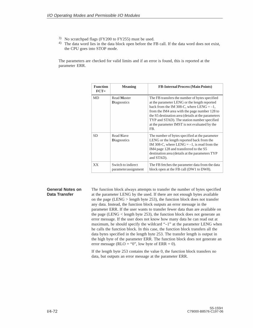
I/4-72S5-155H
C79000-B8576-C197-06
3) No scratchpad flags (FY200 to FY255) must be used.4) The data word lies in the data block open before the FB call. If the data word does not exist,
the CPU goes into STOP mode.
The parameters are checked for valid limits and if an error is found, this is reported at theparameter ERR.
FunctionFCT=
Meaning FB-Internal Process (Main Points)
MD Read MasterDiagnostics
The FB transfers the number of bytes specifiedat the parameter LENG or the length reportedback from the IM 308-C, where LENG = –1,from the IM4 area with the page number 128 tothe S5 destination area (details at the parametersTYP and STAD). The station number specifiedat the parameter IMST is not evaluated by theFB.
SD Read SlaveDiagnostics
The number of bytes specified at the parameterLENG or the length reported back from theIM 308-C, where LENG = –1, is read from theIM4 page 128 and transferred to the S5destination area (details at the parameters TYPand STAD).
XX Switch to indirectparameter assignment
The FB fetches the parameter data from the datablock open at the FB call (DW1 to DW8).
The function block always attempts to transfer the number of bytes specifiedat the parameter LENG by the used. If there are not enough bytes availableon the page (LENG > length byte 253), the function block does not transferany data. Instead, the function block outputs an error message in theparameter ERR. If the user wants to transfer fewer data than are available onthe page (LENG < length byte 253), the function block does not generate anerror message. If the user does not know how many data he can read out atmaximum, he should specify the wildcard “–1” at the parameter LENG whenhe calls the function block. In this case, the function block transfers all thedata bytes specified in the length byte 253. The transfer length is output inthe high byte of the parameter ERR. The function block does not generate anerror message (RLO = “0”, low byte of ERR = 0).
If the length byte 253 contains the value 0, the function block transfers nodata, but outputs an error message at the parameter ERR.
General Notes onData Transfer
I/O Operating Modes and Permissible I/O Modules

I/4-73S5-155HC79000-B8576-C197-06
If an error occurs when processing the function block, the parameter ERRcontains more detailed information about the cause of the error. The RLO isalso set to “1”.
If the function block reports a parameter error, the cause can be determinedvia the error number (e.g. data block does not exist or is too short).
If the function block is processed without error, the low byte of the parameterERR contains the value zero. The RLO is also set to “0”.
The high byte of the parameter ERR contains the number of bytes transferredif the function block was called with LENG = –1 (wildcard length); in allother cases “0”. The low byte contains the error number if an error occurs. Ithas some bit assignments:
High byte Low byte
Bit 15.. ..8 7.. ..0
Parameter ERR X X X X X X X X X X X X X X X X(or Accu 1) Number of bytes
transferred if wildcardlength –1 is assigned
Currenterror
number
Configuration error
IM error
Group error bit
Assignment of theParameter ERR
I/O Operating Modes and Permissible I/O Modules

I/4-74S5-155H
C79000-B8576-C197-06
The assignment of the parameter data block is only relevant for indirectparameter assignment of the FB 192 IM308C-R. With indirect parameterassignment (FCT = “XX”) the function block takes the parameter data fromthe parameter data block and not from the block parameters. The parameterdata block must be opened and had parameters passed by the user beforecalling FB 192 IM308C-R. The ERR word is then always in DW 8 of theparameter DB.
The parameter data block has the following structure:Recommended
data format
DW 0 Reserved KH
DW 1 DPAD KH
DW 2 IMST KY
DW 3 FCT KS
DW 4 T-AG KS
DW 5 TYP KY
DW 6 STAD KF
DW 7 LENG KF
DW 8 ERR KY/KH
Assignment of theParameter DataBlock
I/O Operating Modes and Permissible I/O Modules

I/4-75S5-155HC79000-B8576-C197-06
4.9.3 Technical Specifications
FB 192 Properties
Function block (Name) FB 192 (IM308C-R)
Library number P71200-S7192-A-1CPU 948R / 948RL
Block length 532 words
Assigned flags FY 200 to FY 255
Data area Parameter DB to DW 8 inclusive 1)
Nesting depth 1
Other Disables interrupts
1) The parameter DB is only necessary for indirect parameter assignment.
I/O Operating Modes and Permissible I/O Modules
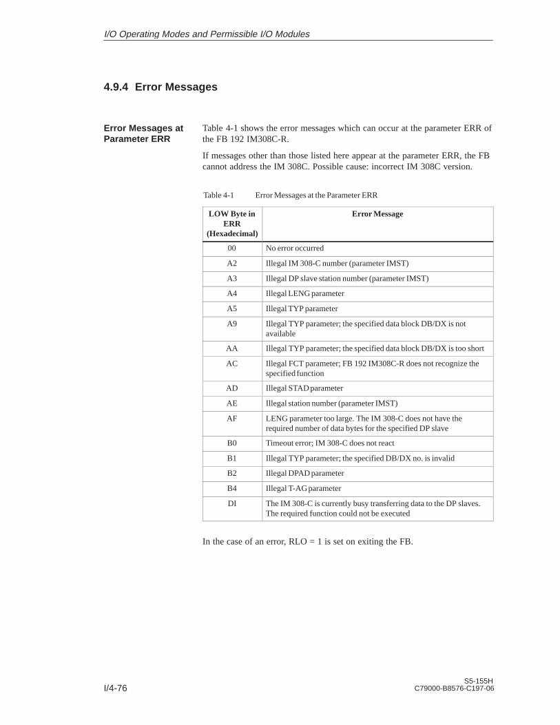
I/4-76S5-155H
C79000-B8576-C197-06
4.9.4 Error Messages
Table 4-1 shows the error messages which can occur at the parameter ERR ofthe FB 192 IM308C-R.
If messages other than those listed here appear at the parameter ERR, the FBcannot address the IM 308C. Possible cause: incorrect IM 308C version.
Table 4-1 Error Messages at the Parameter ERR
LOW Byte inERR
(Hexadecimal)
Error Message
00 No error occurred
A2 Illegal IM 308-C number (parameter IMST)
A3 Illegal DP slave station number (parameter IMST)
A4 Illegal LENG parameter
A5 Illegal TYP parameter
A9 Illegal TYP parameter; the specified data block DB/DX is notavailable
AA Illegal TYP parameter; the specified data block DB/DX is too short
AC Illegal FCT parameter; FB 192 IM308C-R does not recognize thespecified function
AD Illegal STAD parameter
AE Illegal station number (parameter IMST)
AF LENG parameter too large. The IM 308-C does not have therequired number of data bytes for the specified DP slave
B0 Timeout error; IM 308-C does not react
B1 Illegal TYP parameter; the specified DB/DX no. is invalid
B2 Illegal DPAD parameter
B4 Illegal T-AG parameter
DI The IM 308-C is currently busy transferring data to the DP slaves.The required function could not be executed
In the case of an error, RLO = 1 is set on exiting the FB.
Error Messages atParameter ERR
I/O Operating Modes and Permissible I/O Modules

I/5-1S5-155HC79000-B8576-C197-06
Operation of Communications Processorsand Intelligent I/Os in the S5-155H
This chapter discusses the use of intelligent I/Os (IPs) and communicationsprocessors (CPs) in the S5-155H programmable controller in one-sided,switched and redundant configurations. It also covers the data handlingblocks (DHBs) for the S5-155H and when and how to invoke them in theRestart routine and in the cyclic program.
5

I/5-2S5-155H
C79000-B8576-C197-06
5.1 Intelligent I/Os in the S5-155H
Normally, the programmable controller communicates with its intelligent I/Omodules via data handling blocks (DHBs). In some cases, communicationbetween intelligent I/Os and the user program is supported by specificstandard function blocks (FBs). These FBs use the DHBs exclusively forcommunication between the PLC and the IPs/CPs.
In the case of other intelligent I/Os, communication between theprogrammable controller and the intelligent I/Os and/or communicationsprocessors is implemented by module-specific standard FBs.
The data handling blocks (DHBs) for the S5-155H are on the COM 155Hdiskette.
Communications
Operation of Communications Processors and Intelligent I/Os in the S5-155H

I/5-3S5-155HC79000-B8576-C197-06
5.2 One-Sided CP/IP Configurations
In a one-sided configuration, the degree of fault tolerance is no higher thanthat of an S5-155H. Such a configuration may therefore be used only when afailure can be tolerated.
In one-sided CP/IP configurations, you need only configure the interfacenumber and the module-to-subunit assignments (refer to the description ofCOM 155H in this manual).
Interprocessor communication flags (for CPs) may not be used in one-sidedconfigurations.
Incoming data is forwarded to both subunits, regardless of whether thesubunit containing the CP/IP is the master or the standby.
Note
One-sided CPs should be used only for subprocesses which can be sacrificedcompletely in the event of a PLC failure. The software for controlling thesesubprocesses should be implemented in separate blocks which can beinvoked conditionally (only when the relevant PLC is functional; seeexample). Failure to observe this recommendation will result in a continuoustimeout should a PLC fail, which in turn will greatly increase the scan time.
One-sided CPs assigned to subunit A:
STL Explanation
:O F X.1:
:O F X.4:
:JC FB Subproc. A
”PLC in redundant mode” flag,bit 2 1 in the H flag word (high-orderbyte)
Flag for ”Central controller issubunit A”, bit 2 4 in the H flag word(high-order byte)
The subprocess is then controlled only when subunit A is operating.
One-sided CPs assigned to subunit B:
STL Explanation
:O F X.1::ON F X.4::JC FB Subproc.B
The subprocess is controlled only when subunit B is operating.
CommunicationsProcessors(CPs/IPs)
Sample Program
Operation of Communications Processors and Intelligent I/Os in the S5-155H

I/5-4S5-155H
C79000-B8576-C197-06
5.3 Switched CP/IP Configurations
The standby-master switchover is carried out without loss of data, regardlessof whether the CPs/IPs are controlled by H data handling blocks or specialfunction blocks.
All data which the master’s CPU reads from the CPs/IPs is also forwarded tothe standby CPU. Only the master CPU, however, writes to the CPs/IPs; thestandby CPU suppresses write operations.
Interprocessor communication flags (address range FF200 to FF2FF) aresupported only in switched CP/IP mode.
These flags must be configured in data block DB 1. All other settings inDB 1 are irrelevant in this case.
The interprocessor communication output flags are output by the mastercontroller, while the interprocessor communication input flags are passedfrom the master to the standby controller. Direct I/O access to ”switched I/O”IPFs is thus permissible.
EU x
CPU948R
CPU948R
SwitchedI/Os
324
304
304
304
314R
314R
Figure 5-1 Switched I/O Configuration
CPs/IPs
InterprocessorCommunicationFlags
Operation of Communications Processors and Intelligent I/Os in the S5-155H

I/5-5S5-155HC79000-B8576-C197-06
5.4 Redundant Communications Processor (CP) Configurations
There are four configurations for redundant communications processors:
a) Two-channel redundant CP configuration (Figure 5-2)b) Switched redundant CP configuration (Figure 5-3)
A single or double bus may be used.
324R
CP
X
304
CP
X
Figure 5-2 Two-Channel Redundant CP Configurations (Variant a)
324R
304
304
304
EU 185 314R
314R
CP
X
EU 185 314R
314R
CP
X
Figure 5-3 Switched Redundant CP Configurations (Variant b)
CPs/IPs can also be redundant. They can be plugged into switched EUs,which is then called a ”switched redundant” configuration. The CPs can alsobe plugged into the two subunits, which is then called a ”two-channelredundant” configuration.
ConfigurationswithCommunicationsProcessors
CP/IP Redundancy
Operation of Communications Processors and Intelligent I/Os in the S5-155H

I/5-6S5-155H
C79000-B8576-C197-06
Selection criteria:
The best configuration for a given situation depends on the application.
Advantages of a switched redundant configuration:
The CPs/IPs remain redundant even when a central controller fails
The central controllers remain redundant even when a CP/IP fails
Shorter scan time
Disadvantages of a switched redundant configuration:
At least two switched EUs are required.
While a CP/IP is being repaired, the EU into which it was plugged mustbe shut down. This means that all other I/O modules in that expansionunit are shut down as well.
Advantages of a two-channel redundant configuration:
No switched EUs are required.
CP repairs usually require that only redundant components be separatedfrom the power supply.
Disadvantages of a two-channel redundant configuration:
A significant increase in the scan time.
When programming, the two CPs must be regarded as independent modules.How redundancy is handled depends on the required functionality, and mustbe programmed by the user.
If a CP/IP is to be plugged into an EU, you will need at least two EUs. A CPor IP must be plugged into each EU. When data arrives at a CP/IP, it isautomatically forwarded to the other subunit.
In order to implement a two-channel redundant CP configuration, one CPmust be plugged into each subunit. The two CPs reserve different pages, andoperate independently of one another. If data arrives at one CP, it isautomatically forwarded to the other subunit.
The user must program the redundancy function for a switched ortwo-channel redundant configuration himself. The user program must bewritten so as to stipulate which CP/IP is active, and must be able to detect aCP/IP fault and switch, if necessary, to the other CP/IP. The operating systemensures that the data is the same in both subunits. The two CPs/IPs must beregarded as separate, independent modules.
In contrast to redundant I/O modules, redundant CPs and IPs reserve differentaddresses or pages in each subunit.
SwitchedRedundantCPs/IPs
Two-ChannelRedundantCPs/IPs
Operation of Communications Processors and Intelligent I/Os in the S5-155H

I/6-1S5-155HC79000-B8576-C197-06
Installation and Startup
This chapter uses examples to explain the procedures to follow whenconfiguring and programming your programmable controller, as well as theprocedures to follow to put it into operation.
Sections 6.1 to 6.5 build on one another and should therefore be readconsecutively; that is, you should read the entire section even if you want touse only redundant I/Os.
The COM 155H User’s Guide is also relevant to all points in this section.
6

I/6-2S5-155H
C79000-B8576-C197-06
6.1 Installing the S5-155H
The SIMATIC S5 installation guidelines apply.
To avoid confusion, the redundant central controllers should be installed inseparate cabinets. This has the following advantages:
Two redundant power supply units
Less confusion when laying the cables
Better visual monitoring of master and standby
S5-155H with four switched EUs:
ÇÇÇÇÇÇÇÇ
ÉÉÉÉÉÉÉÉ
ÇÇÇÇÇÇÇÇ
ÉÉÉÉÉÉÉÉ
ÇÇÇÇÇÇÇÇ
ÉÉÉÉ
ÉÉÉÉÉÉÉÉ
ÇÇÇÇÇÇÇÇ
Expansionunit 1(EU 185-3UA)
I/O bus from CC 1I/O bus from CC 2Parallel link between CC 1 and CC 2
Load power supply
Voltage distribution
Centralcontroller(CC 155H)
Expansionunit 4(EU 185-3UA)
Cable duct
Load power supply
P. link
IM314R from CC 1 left IM314R from CC 2 rightÉÉÉ
ÇÇÇÇÇÇ
Centralcontroller(CC 155H)
Expansionunit 2(EU 185-3UA)
Cable duct
Expansionunit 3(EU 185-3UA)
Voltage distribution
Figure 6-1 Installing an S5-155H
General Remarks
Example of anInstallation
Installation and Startup

I/6-3S5-155HC79000-B8576-C197-06
The central controllers’ power supply units should be fed from twoseparate and independent circuits.
The power supply for the expansion units must have a fault-tolerantinfeed (e.g. 24 V with backup batteries).
The figure below shows a possible solution:
Circuit 1 Circuit 2
Expansion unit
Power supply unit
Central controller 2
Power supply unit
Central controller 1
Power supply unit
Figure 6-2 Infeed to the Power Supply Units
It is advisable to have separate load power supplies connected to separateand independent circuits in each cabinet. They should be coupled to eachother via diodes in such a way that, if one of the power supply unitsshould fail, the other would take over. Load rating, fusing and conductorcross-section must be selected accordingly.
If you have to run considerable lengths of connecting cables outside thecabinet, make sure the redundant cables are in separate cable ducts. Thisenhances fault tolerance.
Connect all central controllers, expansion units and cabinets to anequipotential bonding conductor with a cross-sectional area of at least10 mm 2 .
The difference in potential when linking up with cable type 721 must be< 7 V.
To improve noise immunity, the shield of the type 721 connecting cablefor the I/O buses of other EUs in a neighboring cabinet and that of the721 cable for the IM 304/IM 314R parallel interface should be connectedto the cabinet via a shield bar.
Also make sure that the I/O buses are uniquely assigned to the centralcontrollers and interface modules. For example:
Central controller 1 = left interface module IM 314R
Central controller 2 = right interface module IM 314R
Please refer to the ”Installation Guidelines” in the S5-135U/155U SystemManual for additional recommendations.
Recommendationsand Rules forHardwareInstallation
Installation and Startup

I/6-4S5-155H
C79000-B8576-C197-06
Note
You must insert a jumper in the two 955 power supply blocks for the135U/155U central controller to deactivate the 24 V watchdog. To do so,loosen the two screws in the power supply block, remove the entire powersupply unit, and insert jumper BA-EX.
Jumper BA-EX must be open in the 955 power supplies for the expansionunits. This corresponds to the factory setting.
When using the IM 304/IM 314-3U... link and several expansion units inseries, note that if the first expansion unit in the phase fails, all otherexpansion units in the phase will also fail. To increase the fault tolerance,only one expansion unit should be provided per phase.
955 Power SupplyBlock
Failure and Repairof One-Sided/RedundantExpansion Unit
Installation and Startup

I/6-5S5-155HC79000-B8576-C197-06
6.2 Configuring the IM 304/IM 324R Parallel Link
It has been assumed that a CPU 948R on which an overall reset has beenperformed is plugged into each subunit, and that the mains power is switchedoff.
Caution: Before interconnecting the two subunits via the IM 304/ IM 324Rinterface modules, check the jumper settings on the IM 304.
Jumper settings on the 6ES5304-3UB... module for a CC-to-CC parallel linkvia the IM 304 and IM 324R interface modules.
Caution: The IM 304 contains electrostatically sensitive components.
Jumper X22 set to ”OFF”Jumper X21 set to ”ON”
X3X4
X3
LED 1
X1
X11
X2
LED 2
9 7 5 3 1
10 8 6 4 2
ONOFF
OFF ON
ONOFF
123X14
123
X22
X21
X15X12
3 2 1
X13
Jumper plug X11
10 to 100 m
Jumperposition
Cable length
X11: Adaption to different cable lengths
*) This setting is permissible only for the IM 304 - IM 324R link in the S5-155H.The length of the link to interface X4 determines the position of jumper X11.
9 7 5 3 1
10 8 6 4 2
9 7 5 3 1
10 8 6 4 2
9 7 5 3 1
10 8 6 4 2
9 7 5 3 1
10 8 6 4 2
9 7 5 3 1
10 8 6 4 2
*)
Max. 10 m
Figure 6-3 Jumper Settings on the 6ES5 304-3UB** Module
Starting Point
Jumper Settingson the IM 304
Installation and Startup

I/6-6S5-155H
C79000-B8576-C197-06
The IM 324R is required to establish a symmetrical 16-bit wide address/datalink to a common dual-port RAM. The frontplate (lower half) is equippedwith a connector for the symmetrical cable. Another connector on the tophalf of the frontplate is for changing modules during operation. It is used toconnect an external voltage source with safe electrical isolation to VDE0160.The voltage range and current range data can be found under TechnicalSpecifications (Section 11.2).
Caution: The IM 324R contains electrostatically sensitive components.
Connector for externalcurrent supply(module replacement)
LED 1
View of the component side
BackplaneconnectorX1
BackplaneconnectorX2Connector
X4
+24V
–
X101/1-2: The jumper configuration must include this jumper (distinguishes between anS5-115H and an S5-155H)
X12 X11
X8 X9
X7
X100
X101
X5
Figure 6-4 IM 324R Jumper Settings (Factory Settings)
IM 324R InterfaceModule
Installation and Startup

I/6-7S5-155HC79000-B8576-C197-06
1. Plug the IM 304/IM 324R modules into slot 131 in each subunit andconnect them with a 6ES5 721-xxx cable.
2. Put the two PLCs into operation successively:
Refer to Section 3.2 (”CPU 948R Installation and StartupProcedures”).
The green LED on the IM 324R must show a steady light (if this is not the case, then the IM 324R is defective).
This allows you to operate the S5-155H in its minimum configuration:
One subunit enters the RUN mode as master upon completion of theself-test; the RUN LED shows a steady light. The RUN LED on theother subunit flashes, showing that it is the standby.
Installation and Startup
I/6-8S5-155H
C79000-B8576-C197-06
6.3 Configuring One-Sided I/Os and Putting Them Into Operation
The two subunits are connected to one another via the parallel link. TheCPUs have been reset (overall reset). The mains power is switched off.
Plug the input, output or CP module you want to operate in one-sidedmode into either subunit A or B or into an expansion unit assigned toeither subunit A or B.
If you plug the module into an expansion unit, be sure to use a suitableinterface module.
Switch on your programmer and start the COM 155H software (on floppy orhard disk) via the S5 command interpreter or the main menu.
Proceed as follows to configure your one-sided I/Os:
1. Choose between digital and/or analog inputs/outputs or CPs in the ”I/OConfiguring” form (refer to Chapter 4 of the COM 155H User’s Guide).
Complete the screen form for each input or output byte or word and foreach CP interface.
For digital or analog inputs/outputs, first set the byte number (invoke the”SEARCH” function and enter the byte number), then enter the relevanttype number.
Only the following types may be specified for one-sided I/Os:
– DI: Type 1
– DQ: Type 8
– AI: Type 13
– AQ: Type 18
You must also specify the subunit (A or B).
2. For a CP in a one-sided configuration, enter the interface number first,then the type number. In this case, you would enter CP Type 24.
Specify the subunit to which the CP is assigned.
3. Press <RETURN> after each entry.
4. Connect your programmer to subunit A or B (Power ON). The CPUs’mode selectors are set to ”STOP”.
5. You must now transfer your configuring data to the PLC.
Starting Point
InitializingOne-Sided I/Os(COM 155H)
Installation and Startup

I/6-9S5-155HC79000-B8576-C197-06
Proceed as follows:
1. Set the mode selector switch of the subunit to which the one-sided I/Osare assigned to RUN.
2. Select ”H-ERROR” in COM 155H’s basic ”DIAGNOSTICS” form. Readany entries you find there, and rectify the problems with the aid of yourmanual.
3. When all errors have been rectified, set the subunit back to STOP.
4. Now set the other subunit to RUN and proceed as described above. Whenyou have once again rectified all errors, switch both CPUs to STOP andload your STEP 5 program into one of the subunits.
5. Now, configure the DB/DX numbers for your STEP 5 program andtransfer DX1 to one of the subunits.
6. Execute a cold restart on that subunit. Following completion of the self-test (RUN LED and STOP LED bothshow a steady light), this subunit will enter the RUN mode as master (theRUN LED shows a steady light).
7. Execute a cold restart on the other subunit. The subunit links up to themaster, receives the user program from the master, and, after completingthe self-test and going through the updating procedures, it enters the RUNmode as standby (the RUN LED flashes).
Putting One-SidedI/Os into Operation
Installation and Startup

I/6-10S5-155H
C79000-B8576-C197-06
6.4 Configuring Switched I/Os and Putting Them Into Operation
An I/O module in an EU 185 is to be operated as a switched I/O (an I/Owhich can be switched from bus to bus).
The expansion unit is connected symmetrically to the two subunits via anIM 304/IM 314R interface module.
1. First, check the jumper settings on the modules.
2. Plug an IM 304 into one of the last four slots in subunit A and subunit B.
3. Plug an IM 314R into slots 145 and 156 of the EU 185.
Jumper settings on a 6ES5304-3UB... module with a symmetrical CC-EUlink via IM 304/IM 314R.
X15X3X4
X3
LED 1
X1
X11
X2
LED 2
9 7 5 3 1
10 8 6 4 2
ONOFF
OFF ON
ONOFF
123X14
123
X22
X21
X12
Jumper X21/X22 ”OFF”when no expansion unitis connected.
X13
Starting Point
Jumper Settingson the IM 304
Installation and Startup

I/6-11S5-155HC79000-B8576-C197-06
*)
9 7 5 3 1
10 8 6 4 2
Jumper plug X11
9 7 5 3 1
10 8 6 4 21 to 100 m
9 7 5 3 1
10 8 6 4 2
9 7 5 3 1
10 8 6 4 2
9 7 5 3 1
10 8 6 4 2
Jumperposition
Cable length
X11: Adaptation to different cable lengths
*) These settings are permissible for the IM 304 - IM 324R link in the S5-155H only.The longest link to interface X3 or X4 determines the position of jumper X11.
100 to 250 m 250 to 450 m 450 to 600 m
Figure 6-5 Jumper Settings on the 6ES5 304-3UB... Module
Caution: The IM 314R contains electrostatically sensitive components.
X5
4 LED
View of the component side
BackplaneconnectorX1
BackplaneconnectorX2
ConnectorX4
ConnectorX3
S1
X7 X11
X10
Figure 6-6 Jumper Settings on the IM 314R
IM 314R InterfaceModule
Installation and Startup

I/6-12S5-155H
C79000-B8576-C197-06
X3: Connector for the 721 cable coming directly from the subunit’s IM 304 or, if several EUs are used, from the preceding IM 314R.
X4: Connector for the 721 cable to the next IM 314R or, if this is the last IM 314R on the bus, for the 760-0HA11 terminating-resistor connector.
Interfaces X3 and X4 are galvanically linked; even if the power supply to theEU 185 containing the IM 314R should fail, the bus connection remains fullyintact.
The number of the expansion unit must be set on switch S1, whereby thesame EU number must be set for both IM 314Rs (you must specify a blocknumber (see below) for this EU number during your I/O configuring sessionwith COM 155H).
ON
x = Switch ONo = Switch OFF
Setting the EUNumber
Installation and Startup

I/6-13S5-155HC79000-B8576-C197-06
The IM 314R’s frontplate is equipped with four LEDs:
– The green ”F” LED lights to indicate ”Master” status
– The red ”T” LED lights to indicate ”Test”
– The red ”BF” LED lights when there is a malfunction, orwhen the CC stops
– The yellow ”R” LED lights to indicate ”Standby” and ”Ready to take control”
Table 6-1 LEDs on the IM 314R Frontplate
F T R BF Operational status
– – – ON CC at STOP or failed or standby is restarting
ON ON – – Master is restarting
ON – – – Master is in RUN mode
– – ON – Standby is in RUN mode
– ON – – EU not configured and associated CC is in RUN mode
– – – – Not configured and EU power OFF/ON
The IM 314R disables the expansion unit’s digital outputs (BASP signal) inthe following situations:
– When both subunits generate a BASP signal
– When the IM 314R is in ”Test” mode
– When both subunits are switch off or when both of an EU’s I/O busesare defective
The IM 314R cannot access the EU bus as long as the EU BASP signal ispresent.
Plug both IM 314Rs into the EU (slots 145 and 156). Insert the 721 cablefrom the subunit’s IM 304 into the upper front connector X3 on theIM 314R. Connector X4 is for the 760-0HA11 terminating resistor.
The following parameters are required to configure your switched I/Os:
1. In COM 155H’s ”IM 314R” form, specify the I/O area for your EUnumbers (must be identical to the setting on the IM 314R).
This is done by entering a block number. Example:
”I/O area for EU No. 5: O Address area FF000H to FF0FFH”
2. Press <RETURN> after each entry.
LEDs on theFrontplate
Command OutputDisable (BASP)Signal
InitializingSwitched I/Os(COM H)
Installation and Startup

I/6-14S5-155H
C79000-B8576-C197-06
3. Specify whether you want to operate digital and/or analog inputs/outputsor CPs/IPs in Switched mode by making the appropriate entry inCOM 155H’s basic ”Configuration of the I/Os” form.
Fill out a form for each input or output byte or word and for each CP/IPinterface.
For digital or analog inputs/outputs, first set the byte number (invoke the”SEARCH” function, then enter the byte number), then enter the typenumber.
The following types may be used as switched I/Os:
– DI Type 2
– DQ Type 9
– AI Type 14
– AQ Type 19
4. For a switched CP or IP, first enter the interface number, then the typenumber. In this case, that would be CP/IP Type 25.
5. Press <RETURN> after each entry.
6. Transfer your configuring data to the PLC as described in the sectiondealing with one-sided I/Os (COM 155H ”System Handling” form).
The programmer must be interfaced to either subunit A or B (power ON),and the mode selectors on both CPUs must be set to ”STOP”. Proceed asfollows:
1. Set subunit A to RUN.
2. Load the error DB from the PLC into the programmer and read anyentries you find there (screen COM 155H’s basic ”DIAGNOSTICS” form,then call the ”H ERRORS” submenu). Rectify any errors you find withthe help of your manual.
3. Switch subunit A back to STOP.
4. Repeat for subunit B.
5. Now configure the DB/DX numbers in your STEP 5 program usingCOM 155H’s ”TRAFDAT” form.
6. When all errors have been rectified, load your STEP 5 program into oneof the subunits.
7. After you have loaded the complete DX 1 configuring data block into thePLC, execute a cold restart on both subunits. Subunits A and B will thenenter the RUN mode, one as master, the other as standby (the master’sRUN LED will show a steady light, the standby’s RUN LED will flash).
Putting SwitchedI/Os into Operation
Installation and Startup

I/6-15S5-155HC79000-B8576-C197-06
6.5 Configuring Redundant I/Os and Putting Them Into Operation
You must have two of every module you want to operate in a redundantconfiguration. One of the modules is plugged into a permissible slot insubunit A, or into an EU of subunit A, the other into subunit B, or into an EUof subunit B. The two modules must have the same address in both subunits.
The subunits are connected to each other via an IM 304/IM 324R parallellink. Each subunit has its own CPU 948R, both of which are reset (overallreset). Both subunits are at POWER OFF, and both are equipped with thesame I/O module.
The following parameters are required to configure your redundant I/Os:
1. You must make the following entries in COM H’s ”Initialize operatingsystem” form:
– Standard discrepancy time
– Readback delay
– IB 0 as redundant interrupt DI byte (yes or no)
2. When you have entered all parameters, press <RETURN>.
3. Specify in COM 155H’s basic ”Configuration of the I/Os” form whetheryou want to configure digital or analog I/Os or CPs.
4. Fill in a form for each redundant input or output and for each redundantCP:
For digital or analog inputs/outputs, specify the byte number first(”SEARCH” function: Enter byte number), then enter the Type number.
Only the following types can be used as redundant I/Os:
– DI Types 3 and 4
– DQ Types 10 and 11
– AI Types 15 and 16
– AQ Types 20 and 21
5. Fill out the right field in the bottom half of the screen in each form bymaking the following entries:
Redundant DIs– An L-DI– An L-DQ– Discrepancy times for the individual DI bits (confirm or change)
for DIs with error locating facility
Starting Point
InitializingRedundant I/Os(COM H)
Installation and Startup

I/6-16S5-155H
C79000-B8576-C197-06
Redundant DQs– An L-DI– An L-DQ– A Readback DI– Type specification for the R-DI (one-sided in subunit A or B,
switched in the P or O I/O area)
for DQs with error locating facility
Redundant AIs
– The absolute discrepancy value
– The relative discrepancy value
– The preferred discrepancy value for an AI
– The lower limit of the analog value
– The upper limit of the analog value
– The discrepancy time (confirm or change)
Redundant AQs
– An L-DQ for AQs with error locating facility
– An R-AI
– The absolute discrepancy value
– The discrepancy time (confirm or change)
– The number of updates within the discrepancy time
6. Press <RETURN> after completing the configuration of the I/O.
The programmer is connected to subunit A or B (power ON). The modeselector switches on both CPUs are at ”STOP”.
1. Transfer your configuring data to the PLC as described in the section onone-sided I/Os (COM 155H’s basic ”System Handling” form).
2. Set subunit A to RUN.
3. Load the error DB from the PLC into the programmer and read anyentries you find (COM 155H’s basic ”Diagnostics” form, ”H ERRORS”submenu). Rectify any errors you find with the help of your manual.
4. Switch subunit A back to STOP.
5. Repeat the above for subunit B.
6. Now configure the DB/DX numbers for your STEP 5 program in the”TRAFDAT” form.
7. When all errors have been rectified, load your STEP 5 program into theS5-155H.
8. When the complete DX 1 configuring data block has been loaded into thePLC, execute a cold restart on both subunits. Subunits A and B then enterthe RUN mode, one as the master, the other as standby (the master’s RUNLED will show a steady light, the standby’s RUN LED will flash).
Note:To document your configuring data on paper, have COM 155H print anoverview (do so by invoking the ”Print” menu in the ”System Handling”form).
Putting RedundantI/Os into Operation
Installation and Startup

I/6-17S5-155HC79000-B8576-C197-06
6.6 S5-155H Responses to Faults/Errors
The example below illustrates how the S5-155H responds to a fault.
FB 37 scans the newest error block for error code YY. If this error/fault ispresent, the controller can respond accordingly.
STL Explanation
OB 37
SEGMENT 1
:JU FB37NAME :ERR–EVAL
:BE
STL Explanation
FB 37
SEGMENT 1 0000
NAME :ERR–EVAL
0005 :MBA0006 :LRW +10008 :+D0009 :MAB000A :LRW +0000C :L KB 255000D :AW000E :L KB YY000F :!=F0010 :JC= M0010011 :JU =BE0012 M001 :0013 :0014 :0015 BE :0016 :BE
Address of error DB Pointer to current error block
Load –error code
Error code YY?
Program the response to error code YY here
Sample Program
Installation and Startup

I/6-18S5-155H
C79000-B8576-C197-06
Installation and Startup

I/7-1S5-155HC79000-B8576-C197-06
Time Characteristics of the S5-155H
The S5-155H programmable controller’s dynamic response differs in anumber of ways from that of the S5-155U. This applies to
Statement execution times
System program runtimes
Restart time
Standby activation
Function blocks
On-line programmer functions
7

I/7-2S5-155H
C79000-B8576-C197-06
7.1 Statement Execution Times for the S5-155H
The majority of STEP 5 statements take the same amount of time to executein the S5-155H as they do in the S5-155U. The STEP 5 statements whichrequire master-standby synchronization, however, are an exception.
Direct I/O access operations to a
– one-sided/two-channel (1-out-of-2) DI approx. 300
– three-channel (1-out-of-3) DI approx. 400
– one-sided/two-channel (1-out-of-2) DQ approx. 200
Direct access to switched I/Os
Note:
These execution times depend on
– the length of the cables and
– the modules used (acknowledgement time).
General Remarks
StatementExecution Timesfor Access toSwitched I/Os
Time Characteristics of the S5-155H

I/7-3S5-155HC79000-B8576-C197-06
7.2 System Program Runtimes
The 155H system program’s runtime is longer by the value DT than the 155Usystem runtime; DT is composed of the following:
Self-test slice: T1
The self-test slice time can be configured with COM H in increments of2 ms.
I/O test and process image update: T2
The purpose of this test is to unify and monitor redundant I/Os, and isexecuted for those modules only. The increase in the scan time forupdating the process image of redundant I/Os is as follows:
– Per switched digital input byte: 25 s
– Per one-sided digital input byte: approx. 40 s
– Per two-channel digital input byte: approx. 60 s
– Per three-channel digital input byte: approx. 120 s
– Per switched digital output byte: 5 s
– Per one-sided digital output byte: approx. 20 s
– Per two-channel digital output byte: approx. 40 s
– Per interprocessor communication input flag: 25 s
– Per interprocessor communication output flag: 5 s
– Basic load 2 ms
155H system program: T3
An almost constant time increase of approximately 5 ms per cycle isneeded for bus management, link requests, EU failures and the like.
In a best-case situation, the scan time increase as compared with theS5-155U is thus
DT = T1 + T2 + T3
The S5-155H restart routine includes a full-scale self-test, thus significantlyincreasing the S5-155H’s restart time as compared with the S5-155U.
The restart time (TA) is as follows:
For CPUs with 640 Kbytes approx. 8 s
For CPUs with 1664 Kbytes approx. 20 s
Increased S5-155HRuntimes
S5-155H RestartTime
Time Characteristics of the S5-155H

I/7-4S5-155H
C79000-B8576-C197-06
7.3 Dynamic Response on Standby Activation
During standby activation, the self-test is inhibited so as not to load the cycleeven more. The standby controller is activated in two phases:
Phase 1
Updating of the user program and the constants (see Section 3.3).
During this phase, the self-test is inhibited so as not to load the cycle evenmore.
Time needed for phase 1:
– With CPU 948R I: 180 PLC cycles
– With CPU 948R II: 436 PLC cycles
– With CPU 948RL: 36 PLC cycles
Phase 2
Updating of the dynamic data
The amount of time this phase adds to the cycle (on a one-shot basis only,however) depends on several factors:
– Transfer time for flags, counters, timers and RS data
This is a constant value: T7 = approx. 25 ms
– Transfer time for configured data blocks
This is an approximate value: T8 = approx. 4 / word
The one-shot increase in the scan time caused by standby activationprocedures is:
TK = T7 + T8
”Activation” Time
Time Characteristics of the S5-155H

I/7-5S5-155HC79000-B8576-C197-06
7.4 Interrupt Response Time
The minimum interrupt response time allowed by the 155H system programis determined by
the self-test ( Ts )
the I/O test ( Te, Ta and Tg ).
The time value is calculated from the maximum value for the following fourformulas:
1. Ts = 2 ms
2. Te = (n * T-DIr) + (m * T-DIe) + (l * T-DI3) + 1.0 ms
3. Ta = (p * T-DQr) + (q * T-DQe) + 0.5 ms
4. Tg = r * T-DIg
where l, n, m, p, q, r = number of bytes in the process image
T-DI3 = 120 Time for three-channel DIs
T-DIr = 60 s Time for redundant DIs
T-DIe = 40 s Time for single-sided DIs
T-DIg = 25 s Time for switched DIs
T-DQr = 40 s Time for redundant DQs
T-DQe = 20 s Time for single-sided DQs
Normally, the interrupt response time is thus 5 ms, but can increase to asmuch as 20 ms (128 three-channel DI bytes).
Time Characteristics of the S5-155H

I/7-6S5-155H
C79000-B8576-C197-06
Time Characteristics of the S5-155H

I/8-1S5-155HC79000-B8576-C197-06
S5-155H Error Diagnostics
This chapter discusses all error diagnostics facilities for the S5-155Hprogrammable controller. It describes in detail the structure of the error datablock, the block in which the 155H system program enters all errors that aredetected, and it also provides a list of error numbers and explains what thesecodes mean. In addition, it describes in detail the H flag doubleword, errorOB 37, and the structure of the H flag word.
8
I/8-2S5-155H
C79000-B8576-C197-06
8.1 Troubleshooting and Error Handling in the S5-155H
All troubleshooting, error diagnostics and error handling facilities providedfor the S5-155U are also available to you in the S5-155H. In addition, theS5-155H provides a number of different options for error identification anderror handling. Table 8-1 contains an overview of available facilities.
Automatic error identification and error locating facilities for the S5-155Hfunction better when no Block End (BE) operation is programmed in OB 26.
S5-155H-specific error messages
The causes of errors reported via COM H must be eliminated inascending order so that secondary error reports do not maketroubleshooting more difficult.
The elimination of the causes of errors in ascending order is important inan S5-155H system for the following reason:
A number of errors (PEU, for instance) would cause the S5-155U to stop,but would ”only” be reported in an S5-155H system so as not tojeopardize fault tolerance unnecessarily; yet these errors are also criticaland must be eliminated as soon as possible.
Error Recovery
S5-155H Error Diagnostics

I/8-3S5-155HC79000-B8576-C197-06
Table 8-1 Troubleshooting and Error Handling in the S5-155H
PLC Brief DescriptionErrorDiag-nostics
ErrorHand-ling
Fault LED
Control bits
ISTACK
BSTACK
COM 155H”DIAGNOSTICS”
Error DB
Error FBs 19to 34
Error OB 37
H flagdoubleword
H flag word
155U + 155H
155U + 155H
155U + 155H
155U + 155H
155H only
155H only
155U + 155H
155H only
155H only
155H only
Specific combinations of theSTOP/SYSFAULT/INIT/ADF/QVZ and ZYKLEDs on the CPU’s frontplate are indicative ofspecific causes of interruption.
These bits provide information on the currentoperating status, and report all errors which haveoccurred up to that point.
Contains the point of interruption, the bitscurrently set, the contents of the accumulators,and the reason for the interrupt.
Lists all blocks which were invoked prior to theSTOP but not yet completely processed.
You can read out all errors which have occurredin the system and user programs up to that point,including point of interruption and time stamp,with the programmer (error DB is output inplaintext).
The 155H system program uses this block toenter all errors detected during the self-test andduring program processing, complete with errorclass, error no. and the date. The block alsocontains a static error image of all inputs andoutputs and all CP/IP interfaces.
In some cases, the system program invokes therelevant OBs before going into STOP; you canprogram appropriate responses to errors in theseOBs.
The system program invokes OB 37 each time itdetects an error which requires an entry in theerror OB; you can program an appropriateresponse in this OB.
This flag doubleword (FD) provides data for thetime stamp in the error DB. You can use this flagdoubleword to program identifiers helpful indiagnosing errors.
The H flag word’s status byte contains importantinformation on the PLC status. You can initiatespecific requests in the STEP 5 program via thecontrol byte.
X
X
X
X
X
X
X
X
X
X
S5-155H Error Diagnostics

I/8-4S5-155H
C79000-B8576-C197-06
8.2 Error Data Block (E-DB)
You must choose a number between 3 and 255 for this block when you areconfiguring the system (COM 155H):
:
H error DB number (3 to 255): 10
:
The 155H system program than generates the error DB automatically in theRESTART routine, normally with a length of 2 Kwords.
The following entries are of particular importance should an error occur:
Entry in the error image
A static error image is stored in the error DB which is organized in such away that each repairable unit (I/Os, CPs, IPs, IM 314R EU) is assigned itsown bit. These bits are arranged in ascending order of addresses or interfacenumbers. A distinction is also made between repairable units assigned tosubunit A and those assigned to subunit B.
All bits in the image are initially set to ”0”. When the system programdetects an error, the appropriate bit is set to ”1”.
You will find an example under ”DW 6 to DW 279: Static Error Image”.
Entry in the status word
Each error is also assigned to a specific error group (”Parallel link errors”,”I/O errors”, and so on). One bit is reserved in the status word for eachgroup. Each of these group error bits remains at ”1” as long as the errorimage shows at least one error belonging to that group. The error groupsassigned bits in the status word are listed under ”Status Word (DW 3)”.
Entry in the error record
Each error detected by the system program is entered in a so-called errorrecord. An error record comprises eight data words. The exact format of anerror record is described in detail under ”Structure of an Error Record”.
As a rule, every error detected is entered only once in the data block.
IMPORTANT
Each time an error is entered in the error DB, the 155H system programinvokes error OB 37; you can evaluate the error and program an appropriateresponse in this OB.
Entries in the ErrorDB
S5-155H Error Diagnostics

I/8-5S5-155HC79000-B8576-C197-06
15 8 7High Low
0
Error counter
Write pointer
Unassigned
Status word
Address of the 1st error record (400)
Reserved
Static error image DI 0..127 Subunit A
Static error image DI/AI 128..255 Subunit A
Static error image DI 0..127 Subunit B
Static error image DI/AI 128..255 Subunit B
Static error image DI 0..127 Switched
Static error image DI/AI 128..255 Switched
Error image of the O area I 0..255 Switched
Error image of the IPC flagsI 0..255 Switched
Static error image DQ 0..127 Subunit A
Static error image DQ/AQ128..255 Subunit A
Static error image DQ 0..127 Subunit B
Static error image DQ/AQ128..255 Subunit B
Static error image DQ 0..127 Switched
Static error image DQ/AQ128..255 Switched
Error image of the O area Q 0..255 Switched
Error image of the IPC flag Q 0..255 Switched
CP/IP interface error image 0..255 Subunit A
CP/IP interface error image 0..255 Subunit B
CP/IP interface error image 0..255 Switched
Static error image of EU (IM 314R) Subunit A
Static error image of EU (IM 314R) Subunit B
Static error image DI/AI 0..255 Subunit A Q
Static error image DI/AI 0..255 Subunit B Q
Static error image DQ/AQ 0..255 Subunit A Q
Static error image DQ/AQ 0..255 Subunit B Q
Reserved
E. location E. class Error code
Additional info 1
Additional info 2
Additonal info 3
Prog. number Ascending number
Time stamp, second (BCD) Time stamp, minute (BCD)
Time stamp, hour (BCD) Time stamp, day (BCD)
Time stamp, month (BCD) Time stamp, year (BCD)
2nd error record
and additional error records
DW 0
DW 1
DW 2
DW 3
DW 4
DW 5
DW 6 ..13
DW 14 ..21
DW 22 ..29
DW 30 ..37
DW 38 ..45
DW 46 ..53
DW 54 ..69
DW 70 ..85
DW 86 ..93
DW 94 ..101
DW 102 ..109
DW 110 ..117
DW 118 ..125
DW 126 ..133
DW 134 ..149
DW 150 ..165
DW 166 ..181
DW 182 ..197
DW 198 ..213
DW 214
DW 215
DW 216 ..231
DW 232 ..247
DW 248 ..263
DW 264 ..279
DW 280 ..399
DW 400
1
sterrorrecord
DW 408
Structure of theError DB
S5-155H Error Diagnostics

I/8-6S5-155H
C79000-B8576-C197-06
All errors are tallied in this counter. The counter stops when it reaches 32767.It is reset during a cold restart and on depassivation.
The write pointer always points to the beginning (the first data word) of thecurrent error record. The current error record is the record in which the mostrecent error was entered. The write pointer is ’0’ as long as the error DBcontains no errors.
This data word is available to the user.
H system errors can be divided into specific groups. Each bit in the statusword is reserved for one of these groups, and stays set to ’1’ as long as theerror image shows at least one error for that group.
Data word DW 3 in the error DB is reserved as status word; this word has thefollowing format:
UMK MLD GER HW SYS HAN PRJ CP PER PEB PK ANW CPU
215 20
20 : Unassigned
21 : CPU Group error bit for CPU errors
22 : Unassigned
23 : ANW Group error bit for user memory errors (memory card)
24 : PK Group error bit for parallel link errors (IM 304 - IM 324R)
25 : PEB Group error bit for I/O bus errors (IM 304 - IM 314R)
26 : PER Group error bit for I/O errors
27 : CP Group error bit for CP/IP errors (page area)
28 : PRJ Group error bit for configuring errors
29 : HAN Group error bit for data handling errors
210 : SYS Group error bit for system errors
211 : HW Group error bit for hardware errors (defective CPU, for example)
212 : GER Group error bit for device errors (EU power OFF, for example)
213 : MLD Message
214 : Unassigned
215 : UMK ’Error DB full’ identifier
Bit 15 : ’Error DB full’ identifier
This bit is set when all of the data block’s error records are full andsubsequent entries start again with the first error record (ring method).
Data Word DW 0:’Error Counter’
Data Word DW 1:’Write Pointer’
Data Word DW 2:Unassigned
Data Word DW 3:’Status Word’
S5-155H Error Diagnostics

I/8-7S5-155HC79000-B8576-C197-06
DW 4: Address of the 1st error record
DW 4 contains the start address of the first error record in the error DB:Data word number ”400”.
DW 5: Reserved
DW 6 to DW 279: Static error image
The image in these data words shows which I/Os or CP/IP interfaces aredefective.
Example: Static error image of the digital outputs (DQs) assigned tosubunit B.
DW 102
DW 103
DW 109 127 126 125 124 123 122 121 120 119 118 117 116 115 114 113 112
31 30 29 28 27 26 25 24 23 22 21 20 19 18 17 16
215 20
15 14 13 12 11 10 9 8 7 6 5 4 3 2 1 0
Digital outputs DQ 30 and DQ 22 in subunit B are bad when bits 14 and 16in data word DW 103 are ”1”.
If more than one timeout (QVZ) occurs during updating of the process image(or of the interprocessor communication flags), the byte number with thelowest address is entered immediately ; the remaining byte numbers areentered within the next 32 PLC cycles.
Beginning DW 400: Error records
The error records begin in data word DW 400. Each record compriseseight data words.
An error record is filled out for each new error the system programdetects during the cycle. When all error records are full, the next error isentered in the first error record (which begins with DW 400) and the’Error DB full’ identifier (bit 15 of the status word) is set to ”1”.
If several errors are detected during the transfer of the process image toswitched I/Os, only one error record entry is made. The other badaddresses are entered in the error image within the next 32 PLC cycles.
S5-155H Error Diagnostics

I/8-8S5-155H
C79000-B8576-C197-06
15 8 7 0
E. location E. class Error number
Additional info 1
Additional info 2
Additional info 3
Prog. number Ascending number
Time stamp, second (BCD) Time stamp, minute (BCD)
Time stamp, hour (BCD) Time stamp, day (BCD)
Time stamp, month (BCD) Time stamp, year (BCD)
B A RES MA PAS WST HST
7 6 5 4 3 2 1 0
Bits 0 to 3 contain the error response (default is the standard response):
Bit 0 : HST Hard STOP (CPU error, for example)
Bit 1 : WST Soft STOP (signature error in userprogram, etc., for example)
Bit 2 : PAS Passivation (on timeout, discrepancy error, etc., for example)
Bit 3 : Unassigned
Bits 0 to 3=0: MESSAGE
Structure of anError Record
Error Location andError Class
S5-155H Error Diagnostics

I/8-9S5-155HC79000-B8576-C197-06
B A RES MA PAS WST HST
7 6 5 4 3 2 1 0
Bits 4 to 7 describe the error location:
Bit 4 : MA Error occurred in master controller
Bit 5 : RES Error occurred in standby controller
Bit 6 : A Error occurred in subunit A
Bit 7 : B Error occurred in subunit B
If, for example, bits 4 and 7 are ”1”, it is apparent that the error occurred insubunit B, which is currently controlling the process as master.
This produces the following possible combinations:
Bit 6/7 and bit 4/5 = 1: Error occurred in one of the subunits
Bits 6 and 7 = 1: Error occurred in both subunits
Bit 5 = 1: Error occurred in the IM304/IM324R parallel link
Bit 4 = 1: Error occurred in the switched I/Os
Bits 4 and 5 = 1: Comparison error (the Error Search Mode is entered)
The error number is a consecutive number between 1 and 255; each errornumber is assigned to a plaintext.
Example: CPU fault, DI module fault, CP/IP fault, etc. (refer to the table”Structure of an Error Record” on the previous page).
The error location informs the user where a specific error has occurred. Theinformation is contained in up to three data words.
Example: Module address, interface no. etc. (refer to the table ”Structure of an Error Record”)
The number of the system program OB to be executed when an error occursand a consecutive number (= OB subtask) are entered here.
Error Number
Error Location(AdditionalInformation)
Program Numberand ConsecutiveNumber for theService Specialist
S5-155H Error Diagnostics

I/8-10S5-155H
C79000-B8576-C197-06
The current date and time (from the CPU’s system data area) are entered herein the event of an error.
Hour (tens) Hour (units) Day (tens) Day (units)
Month (tens) Month (units) Year (tens) Year (units)
Second (tens) Second (units) Minute (tens) Minute (units)
You can also use the first two data words to store the contents of a specificflag doubleword whose number you specify with COM 155H. Refer also to”H Flag Doubleword” in Section 8.3.
Note
When several timeouts occur in the switched I/Os during updating of thoseI/Os (or of the IPC flags), only one, i.e., the one with the lowest bytenumber, is entered in the error record.
The other byte numbers are entered in the static error image.
Table 8-2 Error List
Error
No.Description Cause of Error Remedy
2 CPU 948R failure (MPU) Hardware fault on CPU or CCpower supply unit’s load voltagemonitor not disabled
Check the jumper setting of theload voltage or replace the CPU948R or phone for maintenance.
3 Message from CPU 948R System error
4 Clock error (CPU 948R) or
battery failure
7 System error Phone for maintenance.
8 BASP error Replace the CPU 948R.
10 I/Os not connected or not ready I/Os not ready. An EU or I/O bus(721 I/O cable) has failed. If aswitched EU has failed, consult thestatic error image.
Time Stamp
S5-155H Error Diagnostics

I/8-11S5-155HC79000-B8576-C197-06
Table 8-2 Error List
Error
No.RemedyCause of ErrorDescription
11 Standby failed to activatesuccessfully
Standby stopped again while beingactivated. The preceding errorusually indicates the reason for thiserror.
Examine the reason why thestandby went into STOP byviewing the contents of theISTACK and the error DB.
13 DX 1 configuring block invalid Generate or modify DX 1 onlyvia COM 155H.
14 DB 1 invalid.info 1:DB 1 ID (ref.)info 2:DB 1 ID (act.)
Generate or correct DB 1 viascreen form.
15 Master stopped during standbyactivation
When the master stops duringactivation, the standby also stops,as the latter has not yet received thecurrent data (flags, for instance).
16 ”Standby STOP” bit set in H flagword
User (program) has set the Hflag bit for ”Standby has stopped”.
17 I/Os ready again This message enables you to reador log the time of a repair or toinitiate depassivation.
18 One master stopped becausepartner also master.
Parallel link error
19 Old standby performs warmrestart as master.
This subunit stopped as standby;other subunit was master on lastsystem STOP. The ex-master hasthe current process data, but is stillat STOP.
a) Always use ”Cold restart without memory”.
b) If this is not possible and standby activation is notrequired, scan OB 37 for this error no. and set the subunit to STOP.
20 Memory module error.info 1:Address (page)info 2:Address (low)
Memory defective. Replace CPU.
21 RAM comparison error.info 1:Block type/block no.
info 2: Relative address
A user RAM location does notmatch in the two subunits, which isnot permissible in a redundantsystem. Assuming there has beenno hardware fault, the reason forthe RAM comparison error isalways one of the following usererrors:a) No interrupt DB/DX specifiedwith COM H.b) Illegal access operation to a bitor a word in the system data area(TBRS n.m., LRS n) executed (seelist in Section 2.4).
The error can usually berectified if the specified DB /DX is entered in the list ofinterrupt DBs/DXs with COMH (see COM H User’s Guide).
S5-155H Error Diagnostics

I/8-12S5-155H
C79000-B8576-C197-06
Table 8-2 Error List
Error
No.RemedyCause of ErrorDescription
22 Checksum error in block.info 1: Sum (ref.)info 2: Sum (act.)info 3: Block type/block no.
Contents of the STEP 5 logic block(OB, PB, SB, FB, FX) illegallymodified, via OUTPUT ADDR orvia the user program.
STEP 5 logic blocks may bemodified by the programmer(output block) or OB 124/125 toensure that the block checksumis correctly entered in DB 0.
23 Error search without result. Error search found no hardwareerrors.
Evaluate error code 21 or 24 inthe error DB for additionaldetails.
24 PIQ comparison error.info 1:Address (page)info 2:Address (low)
The PIQ is not the same in bothsubunits. Possible reasons:- Parallel link error- User programming error;
for example, illegal access to system RAM in order to
change the PIQ.
25 Operating system EPROMfailure.
Bad operating system EPROM. Replace the CPU 948R.
26 PIQ RAM errorinfo 1:Address (page)info 2:Address (low)info 3:Faulty bit no.
27 Memory configurationincompatibility.
In a redundant system, the subunitsmay not have different memoryconfigurations.
Check the SPAUS to see wherethe difference in the memoryconfiguration lies and upgradethe standby accordingly. Afterexecuting an overall reset on thestandby, it can be reactivated(see error no. 21 for furtherdetails).
28 System program incompatibility. In a redundant system, the subunitsmay not have EPROMs withdifferent contents.
Activating the standby when thesubunits are using two differentoperating system versions ispermissible only when thestandby is the one with thenewer version. Prior toactivation, the COM H”UPGRADE” parameter mustbe set to ”CPU 948R”. Thestandby can then be activated,and takes over as master. Theother subunit stops and mustthen be upgraded.
29 Different user program code. The subunits cannot be operatedwith different user memory cards(the block sequence must also bethe same!).
Generate two identical memorycards and activate the first usingCOM 155H’s ”UPGRADE”,”MEMCARD” function (seeChapter 9, ”Upgrading”).
S5-155H Error Diagnostics

I/8-13S5-155HC79000-B8576-C197-06
Table 8-2 Error List
Error
No.RemedyCause of ErrorDescription
30 Standby-master switchover due tomaster failureinfo 1: Instruction codeinfo 2:Absolute SAC (high)info 3:Absolute SAC (low)
The master failed during userprogram processing.
31 Standby failure.info 1: Instruction codeinfo 2: Absolute SAC (high)info 3: Absolute SAC (low)
Standby controller failure duringuser program processing.
32 Synchronization error(master-standby) in the userprogram.info 1: Instruction codeinfo 2:Absolute SAC (high)info 3:Absolute SAC (low)
A subunit waited at thissynchronization point until thewaiting time elapsed. One reasonfor this error might be differencesin the program scan in master andstandby caused by discrepancies inDB contents.
All DBs (DXs) whose contentshave been changed in aninterrupt handling routine mustbe reconfigured as interruptDBs/DXs.
33 Parallel link error(IM 304 / IM 324R)
IM 304, IM 324R or parallel linkcable failed.
34 Synchronization error(master-standby time) inthe operating system
For maintenance purposes. Print out the error DB, theISTACK and the BSTACK andphone for maintenance.
35 Standby-master switchover due tomaster failure
Master failed while the operatingsystem was processing.
36 Standby failure Standby failed while the operatingsystem was processing.
37 Standby-master switchover due toI/O error.info 1: QVZ address (page)info 2:QVZ address (low)
A standby-master switchover iscarried out automatically in theevent of a timeout (QVZ) on aswitched I/O because the operatingsystem assumes that an I/O bus hasfailed. The subsequent errormessage(s) and the static errorimage show what it was that failed(an EU, for instance). Anyadditional timeouts occurring priorto the next passivation do not causeanother transfer.
Rectify the I/O error.Fault-tolerance is restrictedbecause the master’s bus failureprevents a standby-masterswitchover.
38 Synchronization error(master-standby location) in theuser program.info 1:Instruction codeinfo 2:Abs. address (high)info 3:Abs. address (low)
A subunit has recognized that itspeer is waiting at anothersynchronization point. See error no.32 for the cause of error andsuitable recovery measures.
S5-155H Error Diagnostics

I/8-14S5-155H
C79000-B8576-C197-06
Table 8-2 Error List
Error
No.RemedyCause of ErrorDescription
39 Synchronization error(master-standby location) in theoperating system.
For maintenance purposes Print out the error DB, ISTACKand BSTACK and phone formaintenance.
40 I/O bus error(IM 304 / IM 314R)info 1:EU number
EU power supply or IM 314R / IM304 module or I/O bus cablefailure.
Check to see if more than oneerror with no. 40 was entered inthe same cycle. Followingrepairs, H flag bit DPA(depassivation) must be set.
50 Timeout (QVZ) on input moduleinfo 1:QVZ addressinfo 2:(Instruction code)
Module fault or EU failure. Issometimes reported together witherror no. 40 or 10, which might bethe cause of error.
51 Timeout (QVZ) on output moduleinfo 1:QVZ addressinfo 2:(Instruction code)
See error no. 50.
52 Timeout (QVZ) when accessingIB 0(process interrupt active)info 1:QVZ addressinfo 2:Instruction code
See error no. 50.
53 Timeout (QVZ) on inputcommunication flaginfo 1:QVZ addressinfo 2:Instruction code
Incorrect jumper setting on CPs/IPsor EU failure or module fault.See error no. 50.
54 Timeout (QVZ) on outputcommunication flaginfo 1:QVZ addressinfo 2:Instruction code
See error no. 53.
55 Configured DI byte notfound (timeout)info 1:DI address
Configuring error or incorrectjumper setting, module fault or EUfailure.
56 Configured DQ byte notfound (timeout)info 1:DQ address
See error no. 55.
57 Configured AI byte notfound (timeout)info 1:AI address
See error no. 55.
58 Configured AQ byte notfound (timeout).info 1:AQ address
See error no. 55.
S5-155H Error Diagnostics
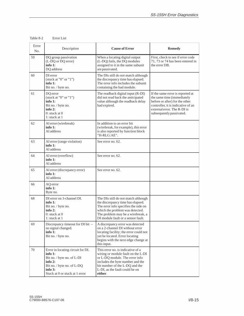
I/8-15S5-155HC79000-B8576-C197-06
Table 8-2 Error List
Error
No.RemedyCause of ErrorDescription
59 DQ group passivation(L-DQ or DQ error)info 1:DQ address
When a locating digital output(L-DQ) fails, the DQ modulesassigned to it in the same subunitare passivated.
First, check to see if error code71, 73 or 74 has been entered inthe error DB.
60 DI error(stuck at ”0” or ”1”)info 1:Bit no. / byte no.
The DIs still do not match althoughthe discrepancy time has elapsed.The error info includes the subunitcontaining the bad module.
61 DQ error(stuck at ”0” or ”1”)info 1:Bit no. / byte no.info 2:0: stuck at 01: stuck at 1
The readback digital input (R-DI)did not read back the anticipatedvalue although the readback delayhad expired.
If the same error is reported atthe same time (immediatelybefore or after) for the othercontroller, it is indicative of anexternal error. The R-DI issubsequently passivated.
62 AI error (wirebreak)info 1:AI address
In addition to an error bit(wirebreak, for example), this erroris also reported by function block”H-RLG:AE”.
63 AI error (range violation)info 1:AI address
See error no. 62.
64 AI error (overflow)info 1:AI address
See error no. 62.
65 AI error (discrepancy error)info 1:AI address
See error no. 62.
66 AQ errorinfo 1:Byte no.
68 DI error on 3-channel DI.info 1:Bit no. / byte no.info 2:0: stuck at 0 1: stuck at 1
The DIs still do not match althoughthe discrepancy time has elapsed.The error info specifies the side onwhich the problem was detected.The problem may be a wirebreak, aDI module fault or a sensor fault.
69 Discrepancy timeout for DI bit –no signal changed.info 1:Bit no. / byte no.
A discrepancy error was detectedon a 2-channel DI without errorlocating facility; the error could notyet be located. Error locatingbegins with the next edge change atthis input.
70 Error in locating circuit for DI.info 1:Bit no. / byte no. of L-DIinfo 2:Bit no. / byte no. of L-DQinfo 3:Stuck at 0 or stuck at 1 error
This error no. is indicative of awiring or module fault on the L-DIor L-DQ module. The error infoincludes the byte number and thebit number of the L-DQ and theL-DI, as the fault could be oneither.
S5-155H Error Diagnostics

I/8-16S5-155H
C79000-B8576-C197-06
Table 8-2 Error List
Error
No.RemedyCause of ErrorDescription
71 Error in locating circuit for DQ.info 1:Bit no. / byte no. of L-DIinfo 2:Bit no. / byte no. of L-DQinfo 3:Stuck at 0 or stuck at 1 error
See error no. 70.Error in the error locating facilityfor redundant DQs.
72 Timeout (QVZ) on ”error locatingDI”.info 1:Byte number of L-DI
L-DI module defective or failure ofthe EU containing the L-DImodule.
73 Timeout (QVZ) on ”error locatingDQ”.info 1:Byte no. of L-DQ
L-DQ module defective or failureof the EU containing the L-DQmodule.
74 Stuck at 0 error of an L-DQ forredundant DQs.info 1:Bit no. / byte no. of the L-DQ
L-DQ bit defective or wiring fault.
75 Readback error.info 1:Byte no. of R-DIinfo 2:Byte no. of associated DQ
If error 61 is reported at the sametime (just before), it has priority.Error no. 75 only indicates that theR-DI is no longer in use.Otherwise, this error no. meansonly that there is a problem withthe R-DI or the wiring.
76 Timeout (QVZ) on readback DI.info 1: Byte no. of R-DIinfo 2: Byte no. of associated DQ
R-DI module defective or failure ofthe EU containing this R-DI.
77 Stuck at 1 – redundant readbackDI.info 1: Bit no. / byte no.info 2: Byte no. of the associatedredundant DQ
The readback input detected signalstate ”1” although the redundantoutput is supposed to output ”0”.
78 Timeout (QVZ) in redundantreadback DI.info 1: Byte no. causing thetimeoutinfo 2: Byte no. of the associatedredundant DQ
Module or EU failure.
79 Stuck at 0 in redundant readbackDI or in redundant DQ.info 1: Bit no. / byte no.info 2: Byte no. of the associatedredundant DQ
Output or readback input defective.
80 CP/IP interface error.info 1:Interface no. (page number)
CP/IP was not configured or CP/IPacknowledges with more than oneinterface number.
S5-155H Error Diagnostics

I/8-17S5-155HC79000-B8576-C197-06
Table 8-2 Error List
Error
No.RemedyCause of ErrorDescription
81 CP/IP does not acknowledge(timeout).info 1:Interface no. (page number)
CP/IP fault or failure of the EUcontaining the CP/IP.
85 Input communication flag notavailable.info 1:Address (F page)
Module fault, PLC failure orconfiguring error. Theinterprocessor communicationinput flag configured in DB 1 doesnot exist. In contrast to the 155U,the 155H allows a coldrestart/warm restart without IPCflag.
86 Output communication flag notavailable.info 1:Address (F page)
See error no. 85.
90 Cannot locate configured DB/DX.info 1:High: 0 = Cyc DB
1 = Cyc DX2 = Interr. DB3 = Interr. DX
Low: DB/DX number
Configuring error.Note:This error increases the length ofthe activation cycle.
91 I/O communication flag ID setmore than once in DB 1.info 1:Illegal identifier
DB 1 not generated via screenform.
Generate DB 1 via screen form.
92 Area ID (I/O comm. flag) missingin DB 1.
See error no. 91.
93 I/O communication flag byte no.> 255 (DB 1)info 1:IPC input/output flag IDinfo 2:Illegal byte number
See error no. 91.
94 > 255 I/O communication flagbytes (DB 1).info 1:IPC input/output flag ID
See error no. 91.
95 DI module not configured.info 1:DI address
Some of the modules being usedhave not been configured, or amodule was incorrectly addressedor acknowledges for more than oneaddress.
96 DQ module not configured.info 1: DQ address
See error no. 95.
97 AI module not configured.info 1: AI address
See error no. 95.
98 AQ module not configured.info 1: AQ address
See error no. 95.
S5-155H Error Diagnostics

I/8-18S5-155H
C79000-B8576-C197-06
Table 8-2 Error List
Error
No.RemedyCause of ErrorDescription
99 DB/DX not configured inTRAFDAT list.info 1:Low: DB/DX numberHigh: 0 = DB, 1 = DX
This DB/DX is modified by theuser program.
Check to see whether DB/DX ismodified in the cyclic programor in an interrupt service routine,and configure the DB/DX in theappropriate list.
101 Prog. attempted illegal I/O access.info 1:Instruction codeinfo 2:Abs. SAC (high)info 3:Abs. SAC (low)
This programming error is detectedin redundant systems only, andmeans that one of the followingwas not observed:a) Block transfers to I/Os must notinvolve the address area forredundant/one-sided I/Os; refer tothe information provided oninitializing operating systemparameters.b) Read access by byte to aredundant AI is not permitted;redundant AIs must be accessed byword in order to enableresult-matching.
105 GDB error in the user program. The interval required betweenblock deletion and block generationwas not observed.
110 Internal CPU 948Rcommunication error.
Interrupts disabled too long.
121 CPU 948R data bus error. CPU 948R hardware fault. Replace CPU 948R.
122 CPU 948R addr. bus error. CPU 948R hardware fault. Replace CPU 948R.
123 CPU 948R EPROM error. CPU 948R hardware fault. Replace CPU 948R.
124 CPU 948R RAM error. CPU 948R hardware fault. Replace CPU 948R.
125 CPU 948R CPU error. CPU 948R hardware fault. Replace CPU 948R.
130 Timeout (QVZ) on 3rd DIchannelinfo 1:Byte no. reporting the timeout.info 2:No. of the associated byte in Aand B
132 Discrepancy error in 3rd DIchannel.info 1:Byte no. for discrepancy.info 2:No. of ass. byte in A and Binfo 3:DL: Permanent 1/0DR: Bit no.
DIs still do not match althoughdiscrepancy time has elapsed. Errorinfo includes the subunit containingthe bad module.
S5-155H Error Diagnostics

I/8-19S5-155HC79000-B8576-C197-06
Table 8-2 Error List
Error
No.RemedyCause of ErrorDescription
136 Discrepancy error in 3rd AIchannel.info 1:AI addressinfo 2:No. of the associated channel in Aand B
The third AI channel differs fromthe other two channels for a longerperiod than that defined by thediscrepancy time.
137 Wirebreak in 3rd AI channel.info 1:AI addressinfo 2:No. of the associated channel in Aand B
138 Overflow in 3rd AI channel.info 1:AI addressinfo 2:No. of the associated channel in Aand B
139 Range violation in 3rd AIchannel.info 1:AI addressinfo 2:No. of the associated channel in Aand B
140 Timeout (QVZ) in readbackanalog input.info 1:Readback AI addressinfo 2:Associated AQ address
Module or EU failure.
141 Wirebreak in readback analoginput.info 1:Readback AI addressinfo 2:Associated AQ address
Wirebreak.
142 Discrepancy in readback analoginput.info 1:Readback AI addressinfo 2:Associated AQ address
The second analog output hasalready been passivated or the PLCis running in Solo mode. If adiscrepancy on this analog channelwas reported within 5 minutes, it isnot the AQ, but rather the AI, thatis defective.
143 Discrepancy: AQ value too high.info 1:AQ addressinfo 2:Actual discrepancy value
The readback analog input reads ahigher value than the one to beoutput to the analog output.
Check/re-measure output valueand replace defective module.
S5-155H Error Diagnostics

I/8-20S5-155H
C79000-B8576-C197-06
Table 8-2 Error List
Error
No.RemedyCause of ErrorDescription
144 Discrepancy: AQ value too low.info 1:AQ addressinfo 2:Actual discrepancy value
The readback analog input reads alower value than the one to beoutput to the analog output.
Check/re-measure output valueand replace defective module.
145 Timeout (QVZ) in locating DQfor redundant AQ.info 1:L-DQ addressinfo 2:Address of the associatedAQ in A and B
Module or EU failure.
150 DB/DX too short or list of dyn.DB/DX unequal.info 1:Block length in master controllerinfo 2:Block length in standby controllerinfo 3:Block number / identifier inmaster controller
The user program on the standbycontroller’s new MEMCARDdiffers from the master controller’suser program, and this difference isnot permitted.
Copy DB/DX block to a newMEMCARD or increase blocklength.
151 Depassivation due to standbyactivation.
The master executed automaticdepassivation as part of the standbyactivation phase. This error isentered in the error list only whenat least one fault/error is reported inthe master controller.
152 Depassivate without deleting theerror records.
H flag control bit X.1 set.
S5-155H Error Diagnostics

I/8-21S5-155HC79000-B8576-C197-06
Interface no.: Interface number for CP/IP errors
SAC: STEP address counter. The STEP address counter points to theabsolute address +1 in the program memory of the last operation executed.
Block type/block number: This block was the last one processed.
215 28 2027
Block type Block number
Block type Block number
1 = DB 0 to 255
2 = SB
4 = PB
5 = FX
8 = FB
12 = DX
16 = OB
IMPORTANT
The error DB is erased in its entirety
– when a cold restart is performed on the master controller
– when you request depassivation by setting the appropriate bit in the H flag word.
Not all error numbers are reserved.
Avoid RAM comparison errors (error search mode) by
configuring all DBs/DXs which are modified in an interrupt OB(OBs 2 to 18) as interrupt DBs/DXs (refer to the COM 155H User’sGuide).
Explanation ofAdditionalInformation
Notes on ErrorDiagnostics
S5-155H Error Diagnostics

I/8-22S5-155H
C79000-B8576-C197-06
You can evaluate the error DB in various ways.
a) Evaluating the error DB on the programmer with COM 155H:
Using the COM 155H ”DIAGNOSTICS” function, you can have the errors inthe error data block output in plaintext. You can scroll up and down throughthe error records on the screen.
b) Evaluating the error DB with STEP 5:
Since the system program automatically invokes the OB 37 user interfacewhen an entry is made in the error DB, it is easy to evaluate the contents ofthe error DB in OB 37 as part of the STEP 5 program in that organizationblock (with the aid of error counters, read and write pointers, status word,and so on) and then to respond suitably to that error (refer to the sampleprogram in Section 6.6).
c) Evaluating the error DB on the programmer using online functions:
Using a series of on-line functions, you can read out the error data block as adata field right directly on the programmer.
The example in this section shows you how to use OB 37 to output theoperating system error messages via CP 523
Preparing the CP 523
1. Plug the memory card into the programmer.
2. Insert the COM 155H diskette in the disk drive and copy the followingblocks from file DB523DST.S5D to the memory card.
– DB 1 Parameter initialization DB (parameters for page length, etc.;refer to the CP 523 manual).
– DB 194
– DB 195
– DB 196
3. Insert the memory card into the receptacle on the CP 523.
4. Set the required module address on the CP 523 (refer to Chapter 5 in theCP 523 manual).
Note
Data block DB 1 contains the printer configuration. The following parameterdefault values are already set:
- V.24; 9600 bps; 2 stop bits; 7 data bits; 1 start bit; no parity (correspondsto the programmer defaults).
- Number of lines: 72.
- If you want a different configuration, you must modify the relevantparameters in DB 1.
Evaluating theError Data Block
Error Messagesfrom the CP 523
S5-155H Error Diagnostics

I/8-23S5-155HC79000-B8576-C197-06
Error information is passed to the CP 523 via an ”Error message block”;FB 48 (which is part of the COM 155H package and stored as file”S5CR70ST.S5D”), which you must call in OB 37.
Calling parameters in OB 37:
STL Explanation
OB 37:JU FB 48
NAME :CP 523 STFBADR :KF +128P/Q :KS OSTDA :KS 24CPUZ :KS JJFEWO :FW 195
:BE
Standard error messages CP 523
NamePara-meterType
DataType
Description Remarks
BADR D KF Module address P/Q = P : BADR = 128 .. 248P/Q = Q : BADR = 0 .. 248
P/Q D KS I/O area P/Q = P: P areaP/Q = Q: O area
STDA D KS Hour representation STDA = 24 : 24-hour representation(German)
STDA = 12 : 12-hour representation(US)
CPUZ D KS PLC clock or CP clock astime source
CPUZ = JJ : The PLC clock is used astime source, making theCOM H FM time and theprinter time the same. Eacherror reported resets the CPclock.
CPUZ = NN : The CP clock is used as thetime source. The COM Herror message time and theprinter output time maydiffer.
FEWO Q FWDW
Value address for error
word
All errors detected by FB 48 during parameterinitialization and processing
Note: Even when set to the O address area, the CP can be plugged into an EU 185which is set for the P address area.
Outputting ErrorMessages
S5-155H Error Diagnostics

I/8-24S5-155H
C79000-B8576-C197-06
FY n FY n+1
7 6 5 4 3 2 1 0 7 6 5 4 3 2 1 0
Kein Fehler-DB vorhanden
Fehler-Nummer nicht zulässig
Peripherie-Bereichskennung P/Q unzulässig
Basisadresse BADR außerhalb der zul. Grenz.
Druckerschnittstelle unklar
Stundendarstellung STDQ unzulässig
nicht belegt
nicht belegt
No error DB
Illegal error code
Invalid I/O area identifier
Base address BADR out of range
Printer port not ready
Invalid hour representation identifier (STDA)
Unassigned
Unassigned
Status of the CP 523
module
in printer mode;
refer to the CP 523
manual
:10.05.91 11:03:01 SUBUNIT B STANDBY SOFT STOP E-NO.: 020
MEMORY MODULE FAULTADDRESS: 0003 0001 H
10.05.91 11:03:01 SUBUNIT A STANDBY PASSIVATION E-NO.: 061DI ERROR (STUCK AT 0 OR STUCK AT 1)BIT NO./BYTE NO. 005,003STUCK AT 001 ERROR
Description of theError Word(FEWO) in FB 48
Sample Printout
S5-155H Error Diagnostics

I/8-25S5-155HC79000-B8576-C197-06
8.3 H Flag Doubleword
The contents of this flag doubleword, whose number you yourself maychoose and stipulate in a COM H run, supplies the time stamp (in the 6th and7th data word of each error record) for all error messages in the error datablock.
You can, for example, use the bits in this doubleword for information usefulin error diagnostics (cycle counter or sequencer status).
Example for flag doubleword FD 45:
u
v
w
x
FY 44
FY 45
FY 46
FY 47
FY 48
FY 49
DW n+2
DW n+3
DW n+4
DW n+5
DW n+6
15 8 7 0
u v
w x
7 0
Flag area Error record in the error DB
If, when configuring the system with COM 155H, you do not specify anumber in the line
:Time stamp flag doubleword (SEC/0..252):SEC:
(see ”SEC” parameter) the internal CPU time is automatically stored in thetime stamp in the event of an error (provided the real-time clock has beenset). This ensures that every error entry is provided with the exact time(second, minute, hour) and date (day, month, year).
Using the H FlagDoubleword
S5-155H Error Diagnostics

I/8-26S5-155H
C79000-B8576-C197-06
8.4 Error Organization Block OB 37
As soon as the 155H system program detects an error (during execution ofthe self-test, for example) and enters it in the error data block, it invokesorganization block OB 37.
OB 37 is the block in which you can program the desired responses to errors;for example to output an error message via the CP 523 and/or set the PLC toSTOP.
If more than one new 155H-specific error occurs in the STEP 5 programwhich makes up OB 37, only the first error is entered as error record.
Tasks Performedby OB 37
S5-155H Error Diagnostics

I/8-27S5-155HC79000-B8576-C197-06
8.5 The H Flag Word
The H flag word contains important information about the status of yourprogrammable controller (such as ”PLC in Error Search Mode”), which youcan also evaluate in OB 37.
You may select the number for the H flag word yourself, and specify itduring your configuring session with COM H:
:H system flag word (0..254): 0:
The H flag word consists of a status byte and a control byte.
The control information can be set bit by bit in the STEP 5 user program.
The information provided in the status byte is read out in the user program.
AGF ADL AMA ZGA ANK MAS RED SOL
7 6 5 4 3 2 1 0
Bit 0 : SOL”Solo mode””1” : PLC is in ”Solo mode””0” : in all other cases
Bit 1 : RED”Redundant mode””1” : PLC is in ”Redundant mode””0” : in all other cases
Bit 2 : MAS”Master”
”1” : CC is master
”0” : CC is standby
In redundant mode
this bit is always 0
Bit 3 : ANK”Standby activation””1” : PLC is in ”Standby activation” mode”0” : in all other cases
Bit 4 : ZGACentral controller is subunit A/B
”1” : CC is subunit A
”0” : CC is subunit B
In redundant mode
this bit is always 0
Format of the HFlag Word
Status Byte(High-Order Byteof FY 0)
S5-155H Error Diagnostics

I/8-28S5-155H
C79000-B8576-C197-06
Bit 5 : AMASubunit”1” : Subunit A is master”0” : Subunit B is master
Bit 6 : ADLUpdating in progress”1” : Standby is being updated”0” : in all other cases
Cyclic DBs/DXs are transferred.The system program automatically resets this bit when updatinghas been completed. The bit can be evaluated only in interruptOBs.
In order to keep the number of interrupt DBs/DXs to a minimum,this bit can be scanned in interrupt service OBs in order to avoidmodifications to the contents of DBs for this brief period of time.
Bit 7 : AGF Note: No automatic switchover possible”1” : PLC fault in switched I/Os”0” : No faults
(PLC faults are, for example, I/O bus failure, DI 0 failure in onesubunit, timeout for switched I/O, etc. An automatic switchover isno longer possible should a secondary fault occur)
RST AUM DPA ARE DPO OAT
7 6 5 4 3 2 1 0
Bit 0 : OAT (No Restart test)Suppress Restart test”1” : Restart master without test”0” : Restart master with test
The system program resets this bit after cold restarts and overallresets.
Bit 1 : DPO (Depassivation without deleting)Depassivate without deleting error records
Bit 2 : ARE (Update standby)Disable updating of the standby controller”1” : Updating of the standby controller disabled”0” : Updating of the standby controller enabled (= default)
Control Byte(Low-Order Byte,e.g. FY 1)
S5-155H Error Diagnostics

I/8-29S5-155HC79000-B8576-C197-06
Bit 3 : Reserved
Bit 4 : DPA (Depassivation)Revoke passivation ”1” : Revoke passivation”0” : in all other cases (default)
Important:This bit must be set using signal edge evaluation; that is, it maybe set once only, and may not be set again until the systemprogram has reset it. The system program resets the bit afterpassivation has been revoked. This bit may not be reset in the userprogram.
Bit 5 : AUM (Switchover request)Switchover requested”1” : Switchover requested ”0” : in all other cases (default)
The system program resets this bit after the switchover has takenplace.
Bit 6 : RST (Standby STOP)Set standby controller to STOP”1” : Set standby controller to STOP”0” : in all other cases (default)
The system program resets this bit after setting the standby toSTOP.
Bit 7 : Unassigned
S5-155H Error Diagnostics

I/8-30S5-155H
C79000-B8576-C197-06
S5-155H Error Diagnostics

I/9-1S5-155HC79000-B8576-C197-06
Dynamic Response to Faults, Repair,Replacement and Upgrading
This chapter discusses the S5-155H’s dynamic response to faults and tomodule, expansion unit and cable failures, and recommends repairprocedures.
It also explains how to replace the memory card and update the CPU.
9

I/9-2S5-155H
C79000-B8576-C197-06
9.1 Failure and Repair of the CPU and Parallel Links
If you have to replace a CPU 948R because of a defect, you will also have toreplace the other CPU 948R if it is not running the same version of theoperating system. To replace a CPU 948R without interrupting operation,proceed as described in Section 9.6.
Should the parallel link between subunit A and subunit B fail, because of awirebreak or a module defect, for example, the master controller continues inSolo mode and the standby controller stops (only when a switched EU ispresent; otherwise refer to the CPU 948R Programming Guide, Section 4.5.1,Cyclic Program Execution ”Special Situation: Operation Without ConnectedEU”).
Proceed as follows to replace a component:
First, replace the 721 cable that connects the IM 304 with the IM 324Rand start the standby controller.
If the link fails again, set the standby controller to ”STOP”. Switch off thepower. Replace the standby controller’s IM 304 (or IM 324R) interfacemodule. Reconnect the IM 304 and the IM 324R and start the standbycontroller.
If the link fails again, proceed exactly as described below, for only thenwill you be able to process your program in NON-STOP mode.
1. Set the standby controller to ”STOP” and switch off the power.
2. Remove the IM 304 or IM 324R from the standby controller and plug in afunctional IM 304.
3. Case-basis decision:
A If the master is equipped with an IM 324R, go to 4.
B If the master is equipped with an IM 304, it must not be removed; anIM 304 cannot be inserted/removed while the controller is in operation(the master would stop). A slot (27 to 123) must be available for thenew IM 324R. (After repairs, the IM 304 and the IM 324R will eachbe in the opposite subunit, but this does not affect the subunitidentification). Now go to 5.
4. Connect the 24 V supply and ground to the appropriate terminals on thefrontplate of the IM 324R. You can use the 24 V output of your centralcontroller ’s power supply unit for this purpose. Now remove thisIM 324R.
5. Connect the 24 V and ground to the appropriate terminals on thefrontplate of the IM 324R (you can use the 24 V output of your centralcontroller ’s power supply unit for this purpose). Plug the IM 324R intothe controller that is currently the master.
Replacing theCentral ProcessingUnit
Replacing theInterface Modules(IMs)
Dynamic Response, Repair, Replacement and Upgrading

I/9-3S5-155HC79000-B8576-C197-06
6. Remove the 24 V source (including ground). The green LED on theIM 324R’s frontplate goes on. Reconnect the IM 304 and the IM 324R.
7. Switch the standby controller on and start it up.
After repairs have been completed and the standby controller has beenactivated, the S5-155H is once again fault-tolerant.
The relevant central controller must always be at STOP and its powerswitched off.
In one-sided/redundant systems, the expansion unit must be switched offwhen replacing the 721 cable connecting an IM 30x and an IM 31x.
In switched configurations, only the standby’s 721 cable may be replacedwhen it connects an IM 304 and an IM 314R. Before doing so, always set thestandby to STOP.
Replacing theIM 30x InterfaceModules in the CC(Excepting thoseused for theParallel Link)
Replacing theIM 30x – IM 31xConnecting Cable
Dynamic Response, Repair, Replacement and Upgrading

I/9-4S5-155H
C79000-B8576-C197-06
9.2 Failure and Repair of Expansion Units (EUs)
The cycle monitoring time must be set accordingly for the S5-155H totolerate an EU failure: per digital/analog I/O byte, the cycle extensionamounts to 1 ms + runtime of the user program in OB 37.
A ”wirebreak” or ”EU power failure” is reported in the form of one of moreerror messages. You can evaluate the timeout information for the relevant I/Omodules. The I/O addresses of these modules are passivated, as otherwisethere would be a continuous timeout. The S5-155H tolerates the failure of allone-sided EUs; that is, both CCs continue operation even without EUs.
When an expansion unit has been repaired, you must depassivate that unit(by setting the ”DPA” bit in the H flag word). The modules plugged into thatunit are then once again entered in the process image. Following activation,the S5-155H is once again fault-tolerant.
If an IM 304 (in the master) or IM 314R (in an expansion unit) fails becauseof a wirebreak (plug pulled), for instance, the 155H system program switchesto the standby. The current master becomes the standby, and reports a fault.
When an EU fails, an ”I/O bus fault” is reported (error no. 40); the user canthen evaluate the fault information.
The S5-155H tolerates the failure of all switched expansion units; that is,both controllers continue to operate, even without EUs. If one of the twocontrollers in a switched configuration fails, the other continues in Solomode.
When a switched EU has been repaired, it is automatically activated in thenext PLC cycle. The modules in that EU are updated.
When an EU fails, the central controller continues to run. The fault isreported and entered in the error data block.
For information on repairs, see ”One-sided EUs”.
Following depassivation, the S5-155H is once again fault-tolerant. Theone-sided I/Os are updated.
Cycle Extension
One-Sided EUs
Switched EUs
Redundant EUs
Dynamic Response, Repair, Replacement and Upgrading

I/9-5S5-155HC79000-B8576-C197-06
9.3 Failure and Repair of I/O Modules
When an I/O module fails, the failure is detected in the S5-155H
through a timeout (QVZ) or
during the self-test.
The module failure is reported.
You can replace the module during operation if you
1. Use the enable input and
2. Remove the front connector before changing the module.
When the I/O module has been repaired and is back in the subrack, it is notactivated until it has been depassivated (by setting the ”DPA” bit in the Hflag word). The module is once again entered in the process image. When theactivation phase has been completed, the S5-155H is once againfault-tolerant.
Replacing an I/OModule
Dynamic Response, Repair, Replacement and Upgrading

I/9-6S5-155H
C79000-B8576-C197-06
9.4 Failure and Repair of CP/IP Modules
In the S5-155H, the failure of a CP/IP module is detected because of atimeout (QVZ). The module failure is reported. ”CP/IP does notacknowledge” is entered in the error DB (a timeout (QVZ) has error no. 81).
1. Switch off the power to the subrack (EU or possibly the CC) containingthe defective CP/IP module before removing it for repairs or replacing itwith another module.
2. Once the CP/IP has been replaced, you must revoke its passivation (bysetting the ”DPA” bit in the H flag word). You must also call the”SYNCHRON” function block (FB 125), which prepares the module forreinclusion.
The module is then activated. Once the activation phase has beencompleted, the S5-155H is once again fault-tolerant.
STL Explanation
::O F 10.0:L KT 150.2:SE T 1:O(:L FY 8:L KH 0000:><F:):O F 10.0:R F 10.0:=F 11.0
Program for CP 1F 10.0 must be set when CP 1is repairedDepassivation takes max. 15 sec.
PAFE byte for CP 1
F 10.0 must be set when theCP 1 is repaired
:JC FB 125NAME :SYNCHRONSSNR : KY0.0BLGR : KY0.6PAFE : FY 8
:A F 11.0:A T 1:BEC::A F 11.0:R F 11.0:JC FBxx:L KB 0:T FY 8
Page no. for CP 1
Depassivation requested?Have 15 seconds elapsed yet?Yes –> BE, as only one CPmay be depassivated at a timeHave 15 seconds elapsed?
Error reported; CP 1 cannotbe depassivated
(Continued on next page)
Replacing a CP/IP
Sample Program
Dynamic Response, Repair, Replacement and Upgrading

I/9-7S5-155HC79000-B8576-C197-06
STL Explanation
:::O F 10.1:L KT 150.2:SE T 1:O(:L FY 9:L KH 0000:><F:):O F 10.1:R F 10.1:=F 11.1:JC FB 125
NAME :SYNCHRONSSNR : KY0.2BLGR : KY0.6PAFE : FY 9
:A T 1:BEC::A F 11.1:R F 11.1:JC FBxx:L KB 0:T FY 9::
Program for CP 2F 10.0 must be set whenCP 2 is repaired.Depassivation takes max. 15 seconds
PAFE byte for CP 2
F 10.1 must be set when CP 2 is repaired.
Page no. for CP 2
Only one CP may bedepassivated at a time
Error reported; CP 2 cannotbe depassivated
Program for CP 3
Dynamic Response, Repair, Replacement and Upgrading

I/9-8S5-155H
C79000-B8576-C197-06
9.5 Standby-Master Switchover
During operation, a standby-master switchover results in the current masterbecoming the standby and the current standby becoming the master. Such aswitchover takes place when
a) the master fails (BASP, NAU or mode selector set to ’STOP’)
b) the first error search (see Section 2.5) on the standby was unsuccessful
c) an IM 314R fails
d) an I/O bus to a switched EU fails
e) a switched I/O module fails
f) the user requests a switchover at the software level (by setting a bit in theH flag word or via COM 155H).
In situation a), the standby controller enters the Solo mode. In case b), thenew standby enters the Error Search mode while the ”old” standby continuesin Solo mode. In cases c) to f), the new standby controller does not stop, butcontinues on as standby.
Via the IM 324R parallel link module, the standby controller checks at everysynchronization point to see if the master is ready. If the standby ascertainsthat the master has failed, it takes the following actions:
The I/O buses of all IM 314Rs are switched.
The two-channel I/Os are switched to one-channel operation.
The ”switchover mode” is entered; that is, the subunits are no longersynchronized.
If the synchronization point is a direct I/O operation to a switched I/O, theoperation is repeated.
Switchover Criteria
Standby-MasterSwitchover whenthe Master Fails
Dynamic Response, Repair, Replacement and Upgrading

I/9-9S5-155HC79000-B8576-C197-06
Standby-Master Switchover
Standby wants to synchro-nize, recognizes that themaster has failed, andswitches over and becomesthe master
OB 1 in the master CC
:T QB z:L DW x :L KB 1:+F
(:T DW x)(:AW )(:. )(:. )(:. )(:L PW y)
OB 1 in the standby CC
:T QB z :L DW x:L KB 1 :+F
:T DW x:AW:.:.:.:L PW y:T FW:A F x.y
Master failure
Synchronization
The one-sided I/Os assigned to the failed subunit are treated as follows:
The process output image (PIQ) is set to ”0”.
The process input image (PII) is set to ”0”.
A timeout (QVZ) is reported in the event of a direct access operation tothese I/Os or this PII/PIQ.
Note
One-sided I/Os should be used only for independent subprocesses, whichare completely passivated in the event of a PLC failure. The software forcontrolling these processes should be stored in separate blocks and calledonly conditionally ; that is, only when the respective subunit is operating.
Event-driven synchronization ensures bumpless standby-master switchoverwhenever necessary; such a switchover has no effect whatsoever on processoutput signals, and there is no loss of information during communicationwith the CPs/IPs.
The switchover time is the once-only increase in scan time caused by astandby-master switchover. From the instant at which the fault/error(synchronization error, for example) is detected, the switchover itself takesno more than 30 ms (full configuration).
The switchover takes up to 3 ms in the event of a CC power supply failure ortotal CPU failure, or when a request for a switchover is made via H flag (fullconfiguration).
One-Sided I/Os inthe Failed Subunit
BumplessSwitchover
Switchover Time
Dynamic Response, Repair, Replacement and Upgrading

I/9-10S5-155H
C79000-B8576-C197-06
9.6 Replacing the Memory Card During Operation
Modifications to the user program in the flash EPROM memory card must bemade known to the operating system via the ”software modification”parameter. When the standby is activated, this parameter prevents acomparison between the 32-bit checksums of the controllers’ memory cards,and the master CPU’s user program is not transferred to the standby CPU.
All data blocks in the standby must come from the memory card. The newdata blocks may be longer, but not shorter than those in the master.
The contents of the data blocks in the COM H list, timers, counters, flags andsystem data are transferred at one synchronization point. Upon completion ofthe activation phase, a standby-master switchover is executed and and CPUwhich is now the standby stops. The ”software modification” parameter isreset.
Once again, in this situation the standby CPU must not create any blockswhen starting up.
The following entries are required:
1. Using COM 155H, set the ”PLC memory card upgrade function”parameter. This effects deactivation of Restart functions ”DB 0comparison” and ”Block transfer”.
2. Set the standby controller to STOP.
3. Replace the standby CPU 948R’s memory card.
4. Execute an overall reset on the standby controller.
5. Execute a cold restart by setting the standby controller to RUN.
This restarts and updates the standby controller. It also initiates anautomatic standby-master switchover and sets the ”old” master to STOP.The ”software modification” parameter is automatically reset.
6. Replace the ”old” master’s memory card.
7. Execute an overall reset and a cold restart with activation of theCPU 948R as standby.
The above sequence makes possible interruption-free software modification(changing of the user program) simply by replacing the memory card.
IMPORTANT
A bumpless switchover from standby to master can only be guaranteed if theuse of the dynamic data is not changed.
Conditions andUpgradingSequence
Operator InputSequence
Dynamic Response, Repair, Replacement and Upgrading
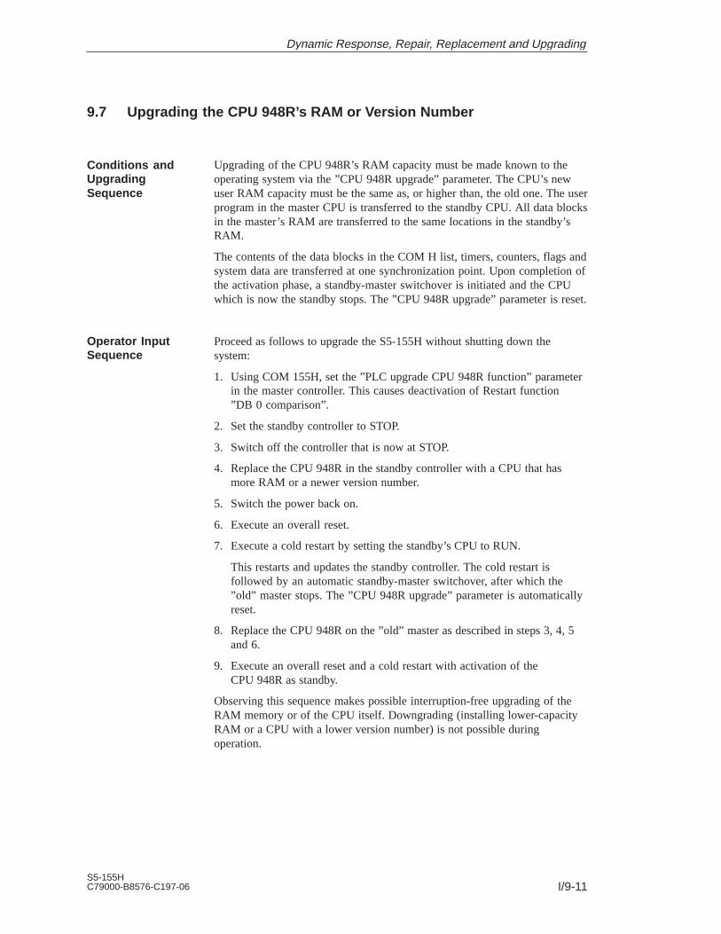
I/9-11S5-155HC79000-B8576-C197-06
9.7 Upgrading the CPU 948R’s RAM or Version Number
Upgrading of the CPU 948R’s RAM capacity must be made known to theoperating system via the ”CPU 948R upgrade” parameter. The CPU’s newuser RAM capacity must be the same as, or higher than, the old one. The userprogram in the master CPU is transferred to the standby CPU. All data blocksin the master’s RAM are transferred to the same locations in the standby’sRAM.
The contents of the data blocks in the COM H list, timers, counters, flags andsystem data are transferred at one synchronization point. Upon completion ofthe activation phase, a standby-master switchover is initiated and the CPUwhich is now the standby stops. The ”CPU 948R upgrade” parameter is reset.
Proceed as follows to upgrade the S5-155H without shutting down thesystem:
1. Using COM 155H, set the ”PLC upgrade CPU 948R function” parameterin the master controller. This causes deactivation of Restart function”DB 0 comparison”.
2. Set the standby controller to STOP.
3. Switch off the controller that is now at STOP.
4. Replace the CPU 948R in the standby controller with a CPU that hasmore RAM or a newer version number.
5. Switch the power back on.
6. Execute an overall reset.
7. Execute a cold restart by setting the standby’s CPU to RUN.
This restarts and updates the standby controller. The cold restart isfollowed by an automatic standby-master switchover, after which the”old” master stops. The ”CPU 948R upgrade” parameter is automaticallyreset.
8. Replace the CPU 948R on the ”old” master as described in steps 3, 4, 5and 6.
9. Execute an overall reset and a cold restart with activation of theCPU 948R as standby.
Observing this sequence makes possible interruption-free upgrading of theRAM memory or of the CPU itself. Downgrading (installing lower-capacityRAM or a CPU with a lower version number) is not possible duringoperation.
Conditions andUpgradingSequence
Operator InputSequence
Dynamic Response, Repair, Replacement and Upgrading

I/9-12S5-155H
C79000-B8576-C197-06
Dynamic Response, Repair, Replacement and Upgrading

I/10-1S5-155HC79000-B8576-C197-06
Typical Applications
This chapter contains sample applications for various configurations of anS5-155H system. When you have worked through these examples, you willhave an H system you can use for any purpose and expand to meet yourspecific requirements.
10

I/10-2S5-155H
C79000-B8576-C197-06
10.1 Task and Required Resources
The steps making up the overall application should be carried out in thefollowing order:
– First, you put the hardware into operation.
– Next, you add switched I/Os.
– Then you add one-sided I/Os to the switched I/Os.
– Finally, you add redundant I/Os with error locating facilities.
The following hardware is required for our sample application:
Two S5-135U/155U central controllers, each with a CPU 948R
One IM 324R interface module
Three IM 304 interface modules
Three 721 interface cables
One EU 185U expansion unit
Two IM 314R interface modules
Three 430 digital input modules
Two 451 digital output modules
Two 760-0HA11 terminators
You require the following software:
COM 155H (version 3.0 or newer)
STEP 5 basic package, level 5
Problem Definition
Hardware
Software
Typical Applications

I/10-3S5-155HC79000-B8576-C197-06
10.2 Installing the Hardware
You are going to install and configure an S5-155H system as shown in thediagram below.
304
Subunit A Subunit B
EU 185U
CPU948R
324R
CPU948R
CPU948R
304
CPU948R
304
314R
314R
The purpose of this step is to establish the parallel link between the two CCsvia the IM 324R and IM 304 (6ES5 304-3UB11) interface modules.
No changes to the jumper settings on the IM 324R are necessary (seeSection 4.2). You must change the jumper settings on the 6ES5 304-3UB.. asshown in the diagram on the next page.
Plug the IM 324R into slot 131 in one of the subunits. This subunit will bereferred to as subunit A.
SystemConfiguration
Establishing aCC-to-CC ParallelLink
Typical Applications

I/10-4S5-155H
C79000-B8576-C197-06
Configure the jumpers on the IM 304 (module 6ES5 304-3UB11) as shown inthe diagram below.
The setting for X11 may not exceed 100 m.
X14
X13
*)
X3X4
X3 X1
X11
X2
LED 2
9 7 5 3 1
10 8 6 4 2
ONOFF
OFF ON
ONOFF
123
123
X22
X21
X15X12
3 2 1
Jumper X22 set to ”OFF”Jumper X21 set to ”ON”Insert the cable into X4
9 7 5 3 1
10 8 6 4 2
Jumper plug X11
Max. 10 m
9 7 5 3 1
10 8 6 4 210 to 100 m
9 7 5 3 1
10 8 6 4 2
9 7 5 3 1
10 8 6 4 2
9 7 5 3 1
10 8 6 4 2
Jumperposition
Cable length
X11: Adaption to different cable lengths
*) These settings are only allowed for interfacing the IM 304 and IM 324R in an S5-155H system.
The length of the link to interface X4 determines the position of jumper X11.
LED 1
Jumper Settingson the IM 304
Typical Applications

I/10-5S5-155HC79000-B8576-C197-06
The purpose of this step is to establish the symmetrical link between the CCand the EU via the IM 304 (6ES5 304-3UB11) in subunits A and B and thetwo IM 314Rs in the expansion unit.
Set the jumpers on the IM 304 (module 6ES5 304-3UB11) as shown in thediagram below.
X13
X3X4
X3 X1
X11
X2
9 7 5 3 1
10 8 6 4 2
ONOFF
OFF ON
ONOFF
123X14
123
X22
X21
X15X12
3 2 1
Set jumper X21/X22to ”OFF” when noexpansion unit isconnected.
*)
9 7 5 3 1
10 8 6 4 2
Jumper plug X11
9 7 5 3 1
10 8 6 4 21 to 100 m
9 7 5 3 1
10 8 6 4 2
9 7 5 3 1
10 8 6 4 2
9 7 5 3 1
10 8 6 4 2
Jumperposition
Cable length
X11: Adaption to different cable lengths
*) These settings are permitted only for interfacing the IM 304 and the IM 324R in anS5-155H system.
The length of the link to interface X3 or X4 determines the position of jumper X11.
100 to 250 m 250 to 450 m 450 to 600 m
LED 1
LED 2
Installing theI/O Bus
Jumper Settingson the IM 304
Typical Applications

I/10-6S5-155H
C79000-B8576-C197-06
10.3 Configuring Switched I/Os
This section shows you how to configure four output bytes (bytes 8 to 11)and three input bytes (bytes 8 to 10) in switched I/Os.
1. Insert the input and output modules with the relevant settings (DI =address 8, DQ = address 8) and readback module into the EU 185U.Connect your programmer to the CPU in subunit A.
2. Call up the Package Selection form on the programmer monitor with”S5”. Position the cursor to the ”COM 155H” line and press function keyF1 to call the COM 155H programming software.
3. After entering the name of the program file and choosing the ”ON” mode,press F6 <EXEC>.
The COM 155H ”Main Menu” form for STEP 5, level 5, appears on thescreen.
CONF PLC CONF FD CONF PG PLC FCT DIAGN. DEFAULTS SYSHAN BACK
COM 155H Main Menu COM 155H / PEC16
F6F5F4F3F2F1 F7 F8
&&
4. Press function key F2 <CONF FD> to select the S5-155H configuringform.
OS IOCONF DELETE BACK
F6F5F4F3F2F1 F7 F8
'&!$"+(*$'&#) &%'
Calling COM 155H
Typical Applications

I/10-7S5-155HC79000-B8576-C197-06
5. Press function key F1 <OS> to screen the softkey menu for ”InitializeOperating System”.
SYSTEM TRAFDAT I/O 314 AREAS BACK
F6F5F4F3F2F1 F7 F8
6. Press function key F1 <SYSTEM>.
No. of test slices (n*2ms) (1...20): 1H error DB number (2...255): 3RAM DB for variable data (2...255): 4H system flag word (0...254): 0Time stamp/F doubleword (SEC/0..252): SECStandard discrepancy time (0.02s...320.00s): 0.05 sDQ Readback delay (0.02s...1.00s): 0.02 sIR DI byte available (Y/N): N
Behavior following RAM/PIQ comparison error (0...4) : 00:Error search mode assume master value1:Standby STOP assume master value2:Error search mode delete odd bits (PIQ)3:Standby STOP delete odd bits (PIQ)4:Collective STOP
BACK
Initialize Operating System COM 155H / PEC16
F6F5F4F3F2F1 F7 F8
7. Enter ”198” as H flag word. Confirm the default values for all otherparameters. Press F8 <BACK> to save the parameters and return to the”Initialize operating system” softkey menu.
8. Press function key F3 <I/O 314>.
Initializing theOperating System(COM 155H)
Typical Applications

I/10-8S5-155H
C79000-B8576-C197-06
Enter area number! ”N” means not reserved
I/O area of EU number 0 : 0 P area FF000H–FF0FFHI/O area of EU number 1 : N not reservedI/O area of EU number 2 : N not reservedI/O area of EU number 3 : N not reservedI/O area of EU number 4 : N not reservedI/O area of EU number 5 : N not reservedI/O area of EU number 6 : N not reservedI/O area of EU number 7 : N not reservedI/O area of EU number 8 : N not reservedI/O area of EU number 9 : N not reservedI/O area of EU number 10 : N not reservedI/O area of EU number 11 : N not reservedI/O area of EU number 12 : N not reservedI/O area of EU number 13 : N not reservedI/O area of EU number 14 : N not reservedI/O area of EU number 15 : N not reserved
BACK
Set System Size COM 155H / PEC16
F6F5F4F3F2F1 F7 F8
9. Since your expansion unit (EU 0) is to be operated in the P area, youmust enter area number ”0” (for P area).
10. Press function key F8 <BACK> to return to the COM 155H main menu.Press function key F2 <IOCONF> to select the softkey menu for”Configuration of the I/Os”.
DI DQ AI AQ CP/IP BACK
F6F5F4F3F2F1 F7 F8
11. Press function key F1 <DI>.
Setting the SystemSize
Typical Applications

I/10-9S5-155HC79000-B8576-C197-06
I/O byte
DI byte 8
DI byte 9
Digital input 9
Type number : 2No. of I/O chan. : 1Fault tolerance : enhanced
DI in switched I/O
Status: TYPE INPUT
SEARCH COPY SELECT DELETE SWAP BACK
Configuration of the I/Os COM 155H / PEC16
F6F5F4F3F2F1 F7 F8
2
Type number
12. Enter the type number ”1” (DI in switched I/O) for bytes 8 to 10, thenpress function key F8 <BACK>. Finally, press function key F2 <DQ> toenter the ”Configuration of the I/Os” screen.
Type number : 9No. of I/O chan. : 1Fault tolerance : enhanced
DQ in switched I/O
Status: TYPE INPUT
I/O byte
DQ byte 8
DQ byte 9
SEARCH COPY SELECT DELETE SWAP BACK
Configuration of the I/Os COM 155H / PEC16
F6F5F4F3F2F1 F7 F8
9
Type number
Configuring DigitalInputs
Configuring DigitalOutputs
Typical Applications

I/10-10S5-155H
C79000-B8576-C197-06
13. Enter type number ”9” (DQ in switched I/O) for bytes 8 to 11.
14. Press function key F8 <BACK> three times in succession to select the”OVERWRITE CONFIGURATION (DX 1) ON FLOPPY?” prompt.Press <INSERT> to return to the COM 155H main menu.
15. Press function key F7 <SYSHAN>, then function key F3 <TRAN/LOAD> to select the softkey menu for ”I/O transfer/load”.
PLCPG PGPLC FDPG PGFD BACK
F6F5F4F3F2F1 F7 F8
16. Transfer the new DX 1 with F2 <PG → PLC> to your subunit A.
17. Press function key F8 <BACK> three times in succession to exitCOM 155H.
Your configuring data (DX 1) is now in subunit A.
18. Execute a cold restart on subunit A. After completion of the self-test (redand green LEDs are on), the CPU enters the RUN mode (green LED ison).
The operating system generates the configured error data block andRAM-DB automatically.
19. Execute a cold restart on subunit B (after an overall reset has beenperformed).
The program in subunit A (master) is transferred to subunit B, and subunitB is ”activated”. The red and green LEDs on subunit B flash alternately.Following termination of the self-test (red and green LEDs show a steadylight), the standby’s CPU also enters the RUN mode. A flashing greenLED shows which subunit is the standby.
You can now write programs just as you did for the S5-155U.
Note:In the standby controller, direct I/O access operations must be suppressedduring startup with the aid of the H flag word (status byte).
In Redundant mode, all write operations are executed on both PLCssimultaneously. Read operations in Redundant mode are the same as in the Usystem.
TransferringConfiguring Data(DX 1)
Starting Up thePLC
On-Line Functions
Typical Applications

I/10-11S5-155HC79000-B8576-C197-06
10.4 Configuring One-Sided I/Os
In this step, two output bytes (bytes 120 and 121) will be configured asone-sided I/Os in subunit A.
1. Insert the output module with the relevant setting (DQ = address 120) andreadback module into subunit A.
2. Press function key F2 <CONF FD> to load DX 1 into the programmer.
3. Press F2 <IOCONF>, then F2 <DQ> to select the ”Configuration of theI/Os” screen so that you can configure your one-sided digital outputs.
I/O byte
DQ byte 120
DQ byte 121
SEARCH COPY SELECT DELETE SWAP BACK
Configuration of the I/Os COM 155H / PEC16
F6F5F4F3F2F1 F7 F8
8
Type number
Type number : 8 Subunit (A/B) : ANo. of I/O chan. : 1Fault tolerance : standard
DQ in one-channel I/O
Status: TYPE INPUT
4. Enter type number ”8” (DQ in one-channel I/O) and subunit ”A” for bytes120 and 121.
5. Press function key F8 <BACK> three times in succession to return to themain menu. Transfer the new DX 1 to the PLC.
Write your programs as you would for an S5-155U. Make sure, however, thatthe output bytes are assigned to only one subunit. When that subunit fails, theI/O bytes assigned to it are no longer available.
Configuring DigitalOutputs
Starting Up thePLC
Typical Applications

I/10-12S5-155H
C79000-B8576-C197-06
10.5 Configuring Redundant I/Os
In this step, or section, which is regarded as a ”separate project”, as it were,you are going to configure one redundant input byte and one redundantoutput byte, each with error locating facility.
1. Insert one 430 input module and one 451 output module with the module address 120 into each of the subunits. Then plug a 430 input module withthe module address 8 into the switched I/O (expansion unit EU 185U).
1. Interconnect the modules as shown in the diagram below.
LED Pin
E+ 1 –E– 2 –L+ 3 –0 4 g –1 5 g –2 6 g –3 7 g –4 8 g –5 9 g –6 10 g –7 11 g –
12 –13 g –14 g –15 g –16 g –17 g –18 g –19 g –20 g –
L– 21 –22 –23 –24 –25 g –26 g –27 g –28 g –29 g –30 g –31 g –32 g –33 –34 g –35 g –36 g –37 g –38 g –39 g –40 g –41 g –42 –
Redun-dant DI
IB 120
LED Pin
E+ 1 –E– 2 –L+ 3 r –0 4 g –1 5 g –2 6 g –3 7 g –4 8 g –5 9 g –6 10 g –7 11 g –
12 r –13 g –14 g –15 g –16 g –17 g –18 g –19 g –20 g –
L– 21 –22 –23 –
L+ 24 r –25 g –26 g –27 g –28 g –29 g –30 g –31 g –32 g –33 –34 g –35 g –36 g –37 g –38 g –39 g –40 g –41 g –42 –
IB 121
IB 123
L-DI
IB 122
Redun-dantDQ
QB 120
QB 121
QB 123
L-DQ
QB 122
Subunit A
L–
L +
0 1 2 3 4 5 6 7
DQDI
(Continued on next page)
InterconnectingI/Os
Typical Applications

I/10-13S5-155HC79000-B8576-C197-06
Typical Applications
LED Pin
E+ 1 –E– 2 –L+ 3 –0 4 g –1 5 g –2 6 g –3 7 g –4 8 g –5 9 g –6 10 g –7 11 g –
12 –13 g –14 g –15 g –16 g –17 g –18 g –19 g –20 g –
L– 21 –22 –23 –24 –25 g –26 g –27 g –28 g –29 g –30 g –31 g –32 g –33 –34 g –35 g –36 g –37 g –38 g –39 g –40 g –41 g –42 –
Redun-dant DI
IB 120
LED Pin
E+ 1 –E– 2 –L+ 3 r –0 4 g –1 5 g –2 6 g –3 7 g –4 8 g –5 9 g –6 10 g –7 11 g –
12 r –13 g –14 g –15 g –16 g –17 g –18 g –19 g –20 g –
L– 21 –22 –23 –
L+ 24 r –25 g –26 g –27 g –28 g –29 g –30 g –31 g –32 g –33 –34 g –35 g –36 g –37 g –38 g –39 g –40 g –41 g –42 –
IB 121
IB 123
L-DI
IB 122
Redun-dantDQ
QB 120
QB 121
QB 123
L-DQ
QB 122
LED Pin
E+ 1 –E– 2 –L+ 3 –
4 g –5 g –6 g –7 g –8 g –9 g –
10 g –11 g –12 –13 g –14 g –15 g –16 g –17 g –18 g –19 g –20 g –
L– 21 –22 –23 –24 r –25 g –26 g –27 g –28 g –29 g –30 g –31 g –32 g –33 –
0 34 g –1 35 g –2 36 g –3 37 g –4 38 g –5 39 g –6 40 g –7 41 g –
42 –
Swit-chedI/Os
IB 8
IB 9
IB 11
IB 10
R-DI
DI DQ DI
L–
L–
L +
0 1 2 3 4 5 6 7
Subunit B EU 185U

I/10-14S5-155H
C79000-B8576-C197-06
3. If you have not yet entered expansion unit EU 0 with area number ”0” (P area), do so now.
Enter area number! ”N” means not reserved
I/O area of EU number 0 : 0 P area FF000H–FF0FFHI/O area of EU number 1 : N not reservedI/O area of EU number 2 : N not reservedI/O area of EU number 3 : N not reservedI/O area of EU number 4 : N not reservedI/O area of EU number 5 : N not reservedI/O area of EU number 6 : N not reservedI/O area of EU number 7 : N not reservedI/O area of EU number 8 : N not reservedI/O area of EU number 9 : N not reservedI/O area of EU number 10 : N not reservedI/O area of EU number 11 : N not reservedI/O area of EU number 12 : N not reservedI/O area of EU number 13 : N not reservedI/O area of EU number 14 : N not reservedI/O area of EU number 15 : N not reserved
BACK
Set System Size COM 155H / PEC16
F6F5F4F3F2F1 F7 F8
4. Press function key F8 <BACK> twice in succession to return to theCOM 155H configuring menu.
5. Press function key F2 <IOCONF>, then function key F1 <DI> to selectthe ”Configuration of the I/Os” screen.
Setting the SystemSize
Typical Applications

I/10-15S5-155HC79000-B8576-C197-06
6. Enter type number ”3” (DI in redundant I/O) for byte 120. Enter ”122.0” as L-DQ and as L-DI bit. Confirm the default values for the discrepancy times.
Type number : 3 L-DQ byte/bit (0.0...255.7): 122.0No. of I/O chan. : 2 L-DI byte/bit (0.0...255.7): 122.0Fault tolerance : high Discrepancy times (0.02 s...320.00 s)
Bit 0: 0.05s Bit 4: 0.05sReadback module required: Bit 1: 0.05s Bit 5: 0.05swith/without L-DI/L-DQ Bit 2: 0.05s Bit 6: 0.05s
Bit 3: 0.05s Bit 7: 0.05s
DI in redundant I/O
Status: TYPE INPUT
I/O byte
DI byte 119
DI byte 120
SEARCH COPY SELECT DELETE SWAP BACK
Configuration of the I/Os COM 155H / PEC16
F6F5F4F3F2F1 F7 F8
3
Type number
7. Press function key F8 <BACK>, then function key F2 <DQ> to select the”Configuration of the I/Os” screen.
8. Enter type ”10” (DQ in redundant I/O) for byte 120. Enter ”122.1” asL-DQ bit and L-DI bit. Enter byte ”11” in switched I/O (”3”) as R-DI (readback digital input).
ConfiguringRedundant Inputs
ConfiguringRedundantOutputs
Typical Applications

I/10-16S5-155H
C79000-B8576-C197-06
I/O byte
DQ byte 119
DQ byte 120
Digital output 120 QB 15
Type number : 10 L-DQ byte/bit (0.0 ... 255.7): 122.1No. of I/O chan. : 2 L-DI byte/bit (0.0 ... 255.7): 122.1Fault tolerance : high R-DI byte ( 0... 255) : 11
R-DI in I/O : 3Readback module required (1: subunit A, 2: subunit B,)with/without L-DI/L-DQ 3: P swit., 4: O swit.)with/without R-DIDQ in redundant I/O
Status: TYPE INPUT
SEARCH COPY SELECT DELETE SWAP BACK
Configuration of the I/Os COM 155H / PEC16
F6F5F4F3F2F1 F7 F8
10
Type number
9. Press function key F8 <BACK> twice in succession to return to theCOM 155H main menu.
10. Transfer the new DX 1 to the PLC.
11. In the main menu, press function key F7 <SYSHAN>, then F4 <PRINT>to select the ”Print menu” screen.
DI DQ AI AQ CP/IP TYPES ALL BACK
F6F5F4F3F2F1 F7 F8
12. Press F1 <DI> and F2 <DQ> for the following printouts of your I/Omodules.
Digital Inputs/Outputs
I/O Byte Symbol Type Subunit I/O Byte Symbol Type Subunit
IB 8 2 IB 9 2
IB 10 2 IB 11 R-DI
IB 120 3 IB 122 L-DI
QB 120 10 QB 122 L-DQ
Printing out theConfiguring Data
Typical Applications

I/10-17S5-155HC79000-B8576-C197-06
10.6 Redundant Point-To-Point Link
To establish a redundant link, you can plug the relevant CP either
into both central controllers (for two-channel redundancy) or
into switched expansion unis (for switched redundancy).
The H-specific special features of a two-channel redundant and of a switchedredundant point-to-point connection are discussed using the CP 525 as anexample.
Establishing links with other CPs, such as CP 523, CP 524, CP 530, CP 544and CP 143, is done in the same way.
The following hardware is required:
One S5-155H in its basic configuration
One S5-115U with power supply unit, CPU and IM 306 as link partner
Four CP 252s
The CP 525 in the S5-155H’s subunit A is referred to as CP AH, the CP 525in subunit B as CP BH. The two corresponding CPs in the S5-115U arereferred to as CP AU and CP BU.
The system is illustrated in Figure 10-1.
CPBU”6”
CPAU”4”
CPBH”2”
IM324R
S5-155H
Link partner:S5-115U
Sub-unitA
CPAH”0”
IM324
Sub-unitB
Figure 10-1 Schematic of a Two-Channel Redundant Point-to-Point Link
Two-ChannelRedundantPoint-to-Point Link
Typical Applications
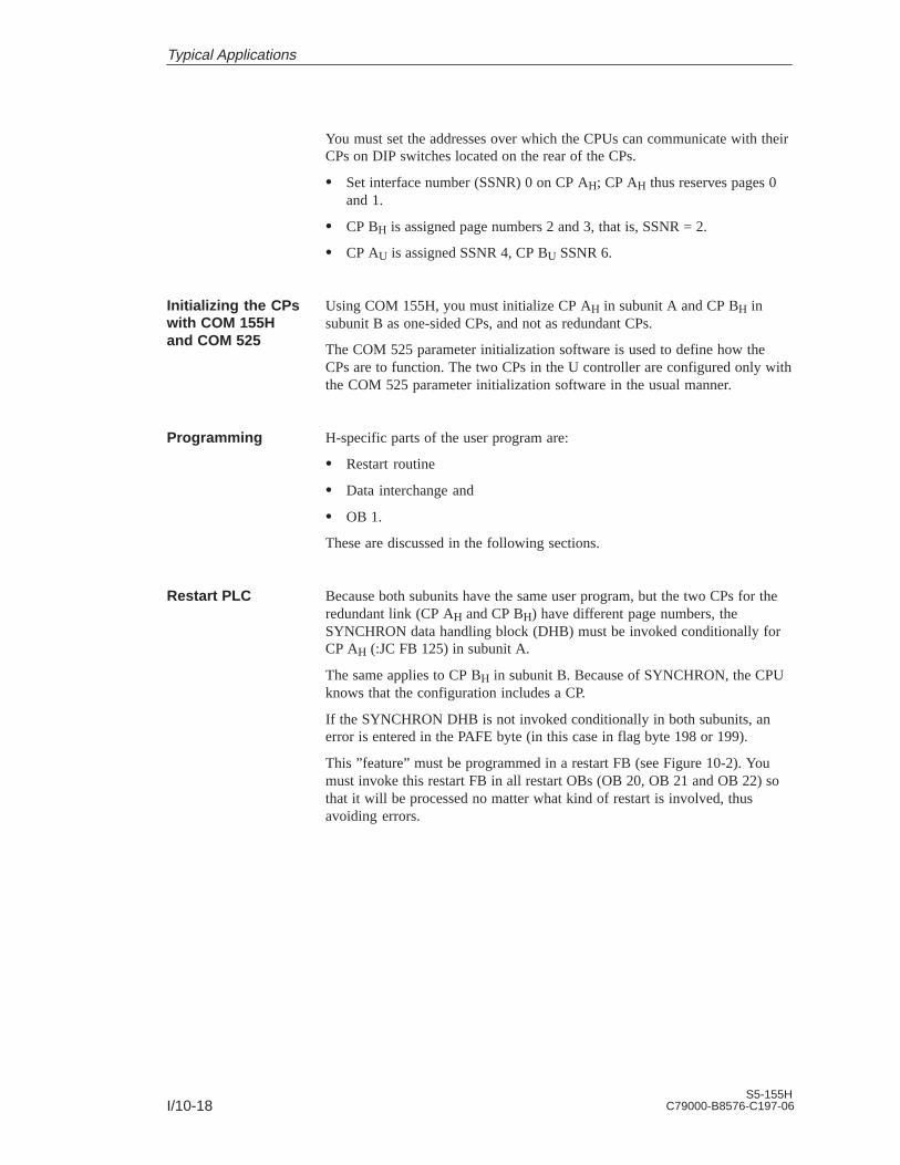
I/10-18S5-155H
C79000-B8576-C197-06
You must set the addresses over which the CPUs can communicate with theirCPs on DIP switches located on the rear of the CPs.
Set interface number (SSNR) 0 on CP AH; CP AH thus reserves pages 0and 1.
CP BH is assigned page numbers 2 and 3, that is, SSNR = 2.
CP AU is assigned SSNR 4, CP BU SSNR 6.
Using COM 155H, you must initialize CP AH in subunit A and CP BH insubunit B as one-sided CPs, and not as redundant CPs.
The COM 525 parameter initialization software is used to define how theCPs are to function. The two CPs in the U controller are configured only withthe COM 525 parameter initialization software in the usual manner.
H-specific parts of the user program are:
Restart routine
Data interchange and
OB 1.
These are discussed in the following sections.
Because both subunits have the same user program, but the two CPs for theredundant link (CP AH and CP BH) have different page numbers, theSYNCHRON data handling block (DHB) must be invoked conditionally forCP AH (:JC FB 125) in subunit A.
The same applies to CP BH in subunit B. Because of SYNCHRON, the CPUknows that the configuration includes a CP.
If the SYNCHRON DHB is not invoked conditionally in both subunits, anerror is entered in the PAFE byte (in this case in flag byte 198 or 199).
This ”feature” must be programmed in a restart FB (see Figure 10-2). Youmust invoke this restart FB in all restart OBs (OB 20, OB 21 and OB 22) sothat it will be processed no matter what kind of restart is involved, thusavoiding errors.
Initializing the CPswith COM 155Hand COM 525
Programming
Restart PLC
Typical Applications

I/10-19S5-155HC79000-B8576-C197-06
STL Explanation
FBxxNAME :ANLAUF
:A F 0.4:JC FB 125
NAME :SYNCHRONSSNR :KY 0.0BLGR :KY 0.6PAFE :FY 198
:AN F 0.4:JC FB 125
NAME :SYNCHRONSSNR :KY 0.2BLGR :KY 0.6PAFE :FY 199
:BE
CC is subunit A
Page no. for CP A H
CC is subunit B
Page no. for CP B H
Figure 10-2 Restart FB for S5-155H
Data can be interchanged in two directions:
S5-155H S5-115U and
S5-155H S5-115U
Depending on how reliable you want the interchange of data to be in aredundant link, you can check both CPs in the S5-115U controller to see if
any data has arrived at all,
the same amount of data has arrived in both, or
the same data has arrived.
The more reliability you want, the more you have to program. In theexample, we have kept to the simplest case, which is ”whether any data hasarrived at all” (see Figure 10-3). In contrast to a ”simple” link, the user needonly
program Send requests for the CP AH and CP BH, and
program the ”Data test” FB.
FB 252 is the standard FB RECEIVE. For detailed information on FB 252,please refer to Catalog ST 57. On the S5-115U, FB 252 is integrated in theoperating system.
Data Interchange
Data InterchangeS5-155H S5-115U
Typical Applications

I/10-20S5-155H
C79000-B8576-C197-06
Redundantlink
S5-115US5-155H
Figure 10-3 Schematic of Data Interchange S5-155H → S5-115U
The user must program SEND requests for CPs AH and BH which transferspecific data from DB 10 to the respective page. These requests must beprogrammed in a function block. In the example, FB 5 is used for CP AH andFB 6 for CP BH. In contrast to a standard computer link, the first word inDB 10 is used as frame counter. FB 5 and FB 6 must be called conditionallyin the S5-155H’s OB 1.
Program: SEND
Send request for SSNR 0 and 2
Error message
no
yes
Jobs terminatedwith error?(PAFE; ANZW)
Increment frame counter
Figure 10-4 Structogram of FB 5 and FB 6
Send Requests forCP AH and CP B H
Typical Applications

I/10-21S5-155HC79000-B8576-C197-06
In the ”Data test” FB, the frame counter in the first word of DBs 20 and 21 isused to ascertain whether the two U CPs have received any data at all. If aU CP is not receiving data, the ”Data test” FB recognizes this fact and reportsit. Figure 10-5 shows a structogram of the ”Data test” FB.
You can program this FB both for S5-155H ← S5-115U and S5-155H →S5-115U.
Yes
No
”Data test”,to see whether the samenumber of messages has
arrived in CP AU and CP BU
Read out data from DB 21 or DB 20
Error message
No
Frame counters in DB
20 and DB 21 notidentical?
When timer expires:counts in DB 20 and
DB 21 identical?
Start watchdog timer(min. 1/2 s)
Read out datafrom error-free
DB
Yes
Figure 10-5 Structogram of the ”Data Test” FB
In this case, too, we have taken as an example the simplest case; that is,whether any data has arrived at all. As for S5-155H → S5-115Uinterchanges, the user must:
program Send requests for CP AU and CP BU, and
program the ”Data test” FB
FB 127 is the standard FB RECEIVE. For detailed information on FB 127,see Catalog ST 57.
The ”Data Test” FB
Data InterchangeS5-155H S5-115U
Typical Applications

I/10-22S5-155H
C79000-B8576-C197-06
In the example (see Figure 10-6), the Send requests for CP AU and CP BU arein FB 15 and FB 16. The structograms for FBs 15 and 16 are the same asthose for FBs 5 and 6 (see Figure 10-4). FB 15 and FB 16 must be calledunconditionally in the S5-115U’s OB 1.
S5-115U
Redundantlink
S5-155H
e.g. FB”Datatest”
Figure 10-6 Schematic of Data Interchange S5-155H S5-115U
FB 5 for CP AH and FB 6 for CP BH are called conditionally in theS5-155H’s OB 1, depending on whether the S5-155H is in Redundant modeor subunit A or B is in Solo mode. Figure 10-7 shows you how you canprogram OB 1.
STL Explanation
OB 1...
:A F 0.1::O F 0.4:JC FB 5
NAME :SUBUNIT A:A F 0.1::ON F 0.4:JC FB 6
NAME :SUBUNIT B:BE
PLC in Redundant mode?PLC not in Redundantmode and subunit Ain RUN mode?
PLC in Redundant mode?PLC not in Redundantmode and subunit Bin RUN mode?
Figure 10-7 Conditional Calling of the ”Send Requests” in OB 1 of the S5-155H
Send Requests forCP AU and CP B U
OB 1 in theS5-155H
Typical Applications

I/10-23S5-155HC79000-B8576-C197-06
The following hardware is needed:
One S5-155H in its basic configuration with two IM 304s, connectingcables and terminating resistor connectors (terminators)
Two EU 185s with four IM 314Rs
One S5-115U with power supply unit, CPU and IM 306 as link partner
Four CP 525s.
The CP 525 in EI 1 of the S5-155H (see Figure 10-8) is referred to asCP 1H, the one in EU 2 as CP 2H. The two corresponding CP 525s in theS5-115U are referred to as CP 1U and CP 2U.
– You could also implement the link using one EU 185. Such a systemwould have a much lower degree of fault tolerance than one with twoEUs, however, since the whole EU would have to be shut down toreplace a CP.
You must set the address (page numbers) over which the CPUscommunicate with their CPs with DIP switches on the CP modules.
Set interface number (SSNR) 0 on CP 1H; CP 1H thus reserves pages 0and 1.
CP 2H is assigned page numbers 2 and 3; that is, SSNR = 2.
CP 1U is assigned SSNR 4, CP 2U SSNR 6.
SwitchedRedundantPoint-to-Point Link
Typical Applications

I/10-24S5-155H
C79000-B8576-C197-06
CP1H
CP2H
CP2U
CP1U
S5-155H
EU 1
EU 2
S5-115U
Figure 10-8 Schematic of a Switched Redundant Point-to-Point Link
Typical Applications

I/10-25S5-155HC79000-B8576-C197-06
Using COM 155H, CP 1H and CP 2H must be configured as switched CPs,not as redundant CPs. You must use the COM 525 parameter initializationsoftware to define how the CPs are to function. The two CPs in the U-seriescontroller are configured only with the COM 525 parameter initializationsoftware.
H-specific parts of the user program are:
Restart routine
Data interchange
OB 1 and
Reactivation of a failed CP
Both subunits have the same user program, but the two CPs for the redundantlink (CP 1H and CP 2H) have different page numbers. Because CP 1H andCP 2H are plugged into switched EUs, the master subunit must besynchronized by invoking FB 125 (:JC FB 125).
If the standby controller also invokes the SYNCHRON data handling block,an error is entered in the PAFE byte (in this case flag byte 198 or 199). Youmust program this ”feature” in a restart FB (see Figure 10-9). This FB mustthen be invoked in all restart OBs (OB 20, OB 21 and OB 22) so that it willalways be processed, no matter what kind of restart is involved, thus avoidingerrors.
STL Explanation
FBxNAME :RESTART
:A F 0.2:JC FB 125
NAME :SYNCHRONSSNR :KY 0.0BLGR :KY 0.6PAFE :FY 198
:A F 0.2:JC FB 125
NAME :SYNCHRONSSNR :KY 0.2BLGR :KY 0.6PAFE :FY 199... :BE
CC is master
Page no. for CP 1 H
CC is master
Page no. for CP 2 H
Figure 10-9 Restart FB for H Controller
Data interchange is exactly the same as over the two-channel redundantpoint-to-point link (see above).
ParameterInitialization withCOM 155H andCOM 525
Programming
PLC Restart
Data Interchange
Typical Applications

I/10-26S5-155H
C79000-B8576-C197-06
FB 5 for CP 1H and FB 6 for CP 2H are invoked unconditionally in theS5-155H’s OB 1 (see Figure 10-10). FBs 5 and 6 were discussed in detail inSection 10.6.
STL Explanation
OB 1...
:JU FB 5......
:JU FB 6...
FB for CP 1 H
FB for CP 2 H
Figure 10-10 Absolute Call of the ”Send Requests” in OB 1 of the S5-155H
Should CP 1H or CP 2H fail, it must be reincluded in the process following itsrepair without a cold or warm CPU restart. This, of course, means that CPsynchronization must take place in the current cycle, which in turn meansthat you must invoke FB (see Figure 10-11) unconditionally in OB 1.
STL Explanation
::O F 10.0:LKT 150.2:SE T 1:O(:L FY 8:L KH 0000:><F
:):O F 10.0:R F 10.0:=F 11.0
Program for CP 1F 10.0 must be set when CP 1 has been repairedDepassivation takes max. 15 sec.
PAFE byte for CP 1
F 10.0 must be set whenCP 1 has been repaired
:JC FB125NAME :SYNCHRONSSNR : KY0.0BLGR : KY0.6PAFE : FY 8
:A F 11.0:A T 1:BEC::A F 11.0:R F 11.0:JC FBxx:L KB 0:T FY 8
Page no. for CP 1
Depassivation requested?15 sec. elapsed?If yes, –> BE, as only one CP can beactivated at a timeHave 15 sec. elapsed?
Error CP 1 cannot bedepassivated
Figure 10-11 FB for Reactivating a Failed CP (continued on next page)
OB 1 in theS5-155H
Reactivating aFailed CP (In-CycleSynchronization)
Typical Applications

I/10-27S5-155HC79000-B8576-C197-06
STL Explanation
:::A F 10.1:L KT 150.2:SE T 1:O(:L FY 9:LKH 0000:><F:):A F 10.1:R F 10.1:=F 11.1:JC FB
125NAME :SYNCHRONSSNR : KY0.2BLGR : KY0.6PAFE : FY 9
:A T 1:BEC::A F 11.1:R F 11.1:JC FBxx:L KB 0:T FY 9::
Program for CP 2F 10.1 must be set when CP 2 has been repairedDepassivation takes max. 15 sec.
PAFE byte for CP 2
F 10.1 must be set when CP 2 has been repaired
Page no. for CP 2
Only one CP may be activated at a time
Error CP 2 cannot be depassivated
Program for CP 3
Figure 10-11 continued
Typical Applications

I/10-28S5-155H
C79000-B8576-C197-06
Typical Applications
I/11-1S5-155HC79000-B8576-C197-06
Technical Specifications:IM 314R / IM 324R
This chapter contains the technical specifications of the IM 314R andIM 324R interface modules.
11

I/11-2S5-155H
C79000-B8576-C197-06
11.1 Technical Specifications of the IM 314R Interface Module
The electronics are accommodated on a printed-circuit board indouble-height Eurocard format. There are two 48-pin connectors of range 2to connect the module to the S5 bus of the expansion unit. The frontplate ofthe module is 1 1/3 standard slots wide and has two 50-pin D-type connectorsfor the symmetrical cable (6ES5 721-0xxx0) and four LEDs.
Supply voltage: + 5 V 5%
Current consumption: approx. 900 mA
Timeout for internal registers: approx. 10 s
Max. cable length fromIM 304 to the last IM 314R 600 m
Max. potential difference between H components(equipotential bonding conductor todesign regulations): 5 V
Max. number of IM 314Rs on the bus: 4
Weight: approx. 350 g
Dimensions: 160 mm x 233.4 mm
Width of frontplate: 20.32 mm
Front connector: Two 50-pin male connectors
Backplane connector: Two 48-pin ES 902, range 2
Operating temperature range: 0 C to 55 C(Operation without fan permissible, but (32 F to 131 F)natural convection must be guaranteed)
Non-operating temperature: – 40 C to + 70 C(– 40 F to + 158 F)
Max. relative humidity: 95 % at 25 C (77 F),no condensation
Max. operating altitude: 3500 m above sea-level
AmbientConditions
Technical Specifications

I/11-3S5-155HC79000-B8576-C197-06
Pin Pin Pin
1 Shield
2 +AD 12
3 - AD12
4 +AD 13
5 - AD13
6 +AD 14
7 - AD14
8 +AD 15
9 - AD15
10 +AD 6
11 - AD 6
12 +AD 7
13 - AD 7
14 +PEU
15 - PEU
16 P’
17 Shield
18 +AD 8
19 - AD 8
20 +AD 9
21 - AD 9
22 +AD 10
23 - AD10
24 +AD 11
25 - AD11
26 +AD 3
27 - AD 3
28 +AD 4
29 - AD 4
30 +AD 5
31 - AD 5
32 +ZGU
33 - ZGU
34 +MEMR/
35 - MEMR/
36 +MEMW/
37 - MEMW/
38 +ALE
39 - ALE
40 +BASP
41 - BASP
42 +AD 0
43 - AD 0
44 +AD 1
45 - AD 1
46 +AD 2
47 - AD 2
48 +RDY/
49 - RDY/
50 Ground
Figure 11-1 IM 314R: Pin Assignment of the X3 and X4 Front Connectors
Pin d b z
2
4
6
8
10
12
14
16
18
20
22
24
26
28
30
32
Shield
A12
A13
A14
A15
M
BASPA/
M
PESP
A 0
A 1
A 2
A 3
A 4
A 5
A 6
A 7
A 8
A 9
A10
A11
BASP
M
+5 V
CPKL/*RESET
MEMR/
MEMW/
RDY/
D 0
D 1
D 2
D 3
D 4
D 5
D 6
D 7
M
Figure 11-2 IM 314R: Pin Assignment of the X1 Backplane Connector
Connector PinAssignment
Technical Specifications

I/11-4S5-155H
C79000-B8576-C197-06
Pin d b z
2
4
6
8
10
12
14
16
18
20
22
24
26
28
30
32
(CPKL/)
+5 V
+5 V
M
SA 0
SA 1
SA 2
SA 3
NAU/
M
M
+5 V
NA 0
NA 1
NA 2
NA 3
M
M
Figure 11-3 IM 314R: Pin Assignment of the X2 Backplane Connector
Technical Specifications

I/11-5S5-155HC79000-B8576-C197-06
11.2 Technical Specifications of the IM 324R Interface Module
The electronics are accommodated on a printed-circuit board ofdouble-height Eurocard format. There are two 48-pin connectors of range 2to connect the module to the S5 bus of the expansion unit. The frontplate ofthe module is 1 1/3 standard slots wide and has two 50-pin D-type connectorsfor the symmetrical cable (6ES5 721-....). The frontplate also has a greenLED and a connector for module replacement during operation (NON-STOPmode). The module also contains MOS components that are sensitive toelectrostatic charge:
Supply voltage: + 5 V 5%
Current consumption: approx. 1000 mA
Memory capacity in the S5-155H: 4 x Kwords
Memory capacity in the S5-115H: 4 x Kwords
Max. access time(with one-sided RAM access: 100 ns
Response time (S5 bus): *) approx. 300 ns
Response time (PK bus): *) approx. 500 ns
Max. cable length from IM 304 to IM 324R: 100 m
Weight: approx. 350 g
Dimensions: 160 mm x 233.4 mm
Front plate width: 20.32 mm
Front connector (X4, bottom): 50-pin, male connector
Backplane connector: Two 48-pin ES 902, range 2
Frontplate connector, top 24 VDC 7 V(for power supply when replacing modules) 14 mA 6 m
Operating temperature range: 0 C to 55 C(Operation without fan permissible, but (32 F to 131 F)natural convection must be guaranteed)
Non-operating temperature: – 40 C to + 70 C(– 40 F to + 158 F)
Max. relative humidity: 95% at 25 C (77 F),no condensation
Max. operating altitude: 3500 m above sea-level
*) The response time is the time between the falling edge of the memoryread (MEMR) or memory write (MEMW) signal at the IM 324R inputand the falling edge of the ready (RDY) signal generated by the IM 324R,provided the RAM is not accessed by the other subunit.
AmbientConditions
Technical Specifications

I/11-6S5-155H
C79000-B8576-C197-06
Note: The signals in parentheses are not transmitted via the interface.
Pin Pin Pin
1 Shield
2 +AD 12
3 - AD 12
4 +AD 13
5 - AD 13
6 +AD 14
7 - AD 14
8 +AD 15
9 - AD 15
10 +AD 6
11 - AD 6
12 +AD 7
13 - AD 7
14 +(PEU)
15 - (PEU)
16 p’
17 Shield
18 +AD 8
19 - AD 8
20 +AD 9
21 - AD 9
22 +AD 10
23 - AD 10
24 +AD 11
25 - AD 11
26 +AD 3
27 - AD 3
28 +AD 4
29 - AD 4
30 +AD 5
31 - AD 5
32 +ZGU
33 - ZGU
34 +MEMR/
35 - MEMR/
36 +MEMW/
37 - MEMW/
38 +ALE
39 - ALE
40 +BASP
41 - BASP
42 +AD 0
43 - AD 0
44 +AD 1
45 - AD 1
46 +AD 2
47 - AD 2
48 +RDY/
49 - RDY/
50 Ground
Figure 11-4 IM 324R: Pin Assignment of the X4 Front Connector
Pin d b z
2
4
6
8
10
12
14
16
18
20
22
24
26
28
30
32
Shield
A12
A13
A14
A15
DSI/
BASPA/
M
A 0
A 1
A 2
A 3
A 4
A 5
A 6
A 7
A 8
A 9
A10
A11
BASP
M
+5 V
CPKL/*RESET
MEMR/
MEMW/
RDY/
D 0
D 1
D 2
D 3
D 4
D 5
D 6
D 7
Figure 11-5 IM 324R: Pin Assignment of the X1 Backplane Connector
Technical Specifications

I/11-7S5-155HC79000-B8576-C197-06
Pin d b z
2
4
6
8
10
12
14
16
18
20
22
24
26
28
30
32
M
M
D 8
D 9
D 10
D 11
M
+5 V
D 12
D 13
D14
D 15
NAU/
Coding plug C79334-A3011-B11Spare Parts
Technical Specifications

I/11-8S5-155H
C79000-B8576-C197-06
11.3 Readback Delays
30 ms each
6ES5 420 :
6ES5 430 :
6ES5 431 :
6ES5 434 :
6ES5 435 :
6ES5 436 :
6ES5 441 :
6ES5 451 :
6ES5 453 :
6ES5 454 :
6ES5 455 :
6ES5 456 :
6ES5 457 :
6ES5 458 :
Total readback delay
30 ms each
60 ms
For redundant 220 V digital modules, the readback delay must be at least100 ms.
When using the ET 100U/ET 200U, the readback delay must be at least2th max.. Please refer to the manual ”ET 100U/ET 200U Distributed I/OSystem” for methods of calculating the value th max.
Digital InputModules
Digital OutputModules
Technical Specifications

I/12-1S5-155HC79000-B8576-C197-06
Glossary
The Glossary, whose contents are listed in alphabetical order, defines themost important 155H-specific terms and functions. Use the keyword index tofind additional information on all terms and topics in the main body of themanual.
12

I/12-2S5-155H
C79000-B8576-C197-06
The system program stores all configuring data entered with COM 155Hduring a configuring session at the programmer in data block DX 1. For thisreason, DX 1 may be used for no other purpose.
An S5-155H can operate only when DX 1 has been loaded.
’Depassivation’ is the opposite of ’passivation’, and therefore revokes theformer. The tests are also reactivated. Following repairs (modulereplacement), depassivation must be initiated.
For a redundant analog input, you may configure a value to serve as themaximum amount by which analog value A (subunit A) may differ fromanalog value B (subunit B). The ’discrepancy value’ is composed of anabsolute portion and a relative portion. Only when this value is exceeded(and the configured discrepancy time has elapsed) does the 155H systemprogram recognize an error.
Redundant digital or analog inputs can show different signal states or inputvalues within a relatively short space of time. The ’discrepancy time’ is thetime period during which the 155H system program will tolerate differentsignal states or input values. The default discrepancy time is 0.05 s, but theuser may set it to a value between 0.01 and 320 s. The system program doesnot recognize an error until this time has elapsed.
Because of a series of comprehensive self-tests, the 155H system programcannot only detect errors and faults quickly, but can also locate them. Withthe aid of this facility, it is possible to find out which modules are defectiveand must be replaced.
A special error locating facility (or LF) must be configured for digital I/Oswhich are to be operated on a NON-STOP basis. As soon as a defectivemodule has been located, the 155H system program automatically shuts thatmodule down and operation from that point on is one-sided.
’Error Search’ mode is invoked when the 155H system program findsdiscrepancies between the RAM contents or process images in master andstandby. In this mode, the master scans the cyclic user program while thestandby executes the self-test to locate the problem.
A ’group’ constitutes all sensors for redundant digital inputs (DIs) or digitaloutputs (DQs) that are served by the same locating digital output (L-DQ).The smallest possible group consists of one redundant DI or DQ byte, thelargest possible group of all redundant DIs or DQs in an S5-155H controller.
Configuring BlockDX 1
Depassivation
Discrepancy Value
Discrepancy Time
Error Locating
Error Search Mode
Group PowerSupply
Glossary

I/12-3S5-155HC79000-B8576-C197-06
The user specifies the number of the ’H flag word’ during his configuringsession with COM 155H. This flag word comprise a status byte and a controlbyte. The system program uses the status byte to store important informationon the current status of the controller. The control byte can be used formaking important requests via the STEP 5 program.
The user specifies the number of the ’H flag doubleword’ during hisconfiguring session with COM 155H. Its contents are of no consequence. Ifno number is specified for the flag doubleword, each entry in the error datablock is automatically stamped with the current date and time from theinternal CPU clock.
Each time it makes an entry in the error data block, the 155H systemprogram copies the contents of the flag doubleword to the 6th and 7th dataword of each error record.
In contrast to a non-intermittent output, an output is said to be intermittentwhen it changes its signal state at least once every hour.
The ’locating facility’ locates errors on redundant digital input/outputmodules.
For each redundant digital input or output for which the 155H systemprogram is not only to detect but also to locate errors, the user must configureone additional input and one additional output.
The S5-155H tolerates the first failure of each redundant hardwarecomponent. The defective components can thus be repaired or replacedwithout having to interrupt program processing.
When a redundant I/O module or communications processor (CP) fails, the155H system program, after locating the problem, shuts it down (that is,passivates it) and operation is one-sided until depassivation takes place.
When an I/O module has to be passivated, the associated group power supplysometimes has to be shut down, thus passivating all other redundant modulesthat share the same power supply.
Once the module goes back on line, it must be depassivated.
Depassivation is usually done in the Restart routine in response to a userrequest. The relevant bit is set in the H flag word (acknowledgement key).
H Flag Word
H FlagDoubleword
IntermittentOutputs
Locating Facility(LF)
NON-STOPOperation
Passivation
Glossary

I/12-4S5-155H
C79000-B8576-C197-06
The digital readback inputs (R-DIs) detect errors in redundant digital outputs.The ’readback delay’ is the amount of time by which the digital readbackinputs (R-DIs) should be delayed.
This delay makes it possible to take into account the different signalpropagation times of the various digital output modules. The defaultreadback delay is 0.01 s, but the user may define a delay of from 0.01 to 1.0 swith COM 155H. If the specified readback delay is shorter than the scancycle time, the 155H system program takes the scan time as readback delaytime.
When the S5-155H operates in Redundant mode, the master controls theprocess. The standby is updated at each synchronization point and checks tomake sure that the master is still functioning properly. If the standbycontroller detects a fault in the master, it simply takes over control.
An I/O module is ’redundant’ when it is ’double’, i.e. when it has the sameaddress in both subunits. If one of the two I/O modules or subunits fails, thefailure is tolerated and their is no interruption in the process. The defectivemodule is reported and can then be replaced or repaired.
The S5-155H supports NON-STOP operation of redundant components witha number of comprehensive self-tests. These check the contents and state ofthe CPUs and I/Os and make comparisons between the two subunits. Thetests execute in the background, and are transparent to the other software,until a hardware failure is detected and located. Every problem detected bythe self-tests is reported.
When the master controller is in Cyclic mode and the standby controller is tobe (re)-instated in the process, for instance during a restart or error search,the 155H system program provides the standby with all of the data from themaster. If necessary, it even transfers the whole user program from the masterto the standby controller (as long as the program is in RAM).
The transfer of this static data can take several cycles. The standby controlleris then updated; that is, within one cycle, it is given the master’s dynamicdata (see ’Updating’). The standby activation phase is complete when theinternal states of master and standby are identical.
Certain events necessitate making the standby the new master, and’demoting’ the master to standby status.
In Redundant mode, for instance, when the standby detects a fault in themaster controller, the standby takes control as soon as the activation phasehas been completed.
The event-driven synchronization of the two subunits ensures that bumplessswitchover is possible at any time.
Readback Delay
Redundant Mode
Redundant I/Os
Self-Test
Standby Activation
Standby-MasterSwitchover
Glossary

I/12-5S5-155HC79000-B8576-C197-06
In ’Solo mode’, the master controls the process alone. The standby is atSTOP or in Error Search mode, and does not participate in the process.
In Solo mode, the S5-155H is like an S5-155U; that is, the two subunits arenot synchronized, but the master continues to execute the self-tests on itsown.
A certain input or output shows stuck at 0 or stuck at 1, and can no longerreacts to a signal change. The 155H system program continually checks allredundant input and outputs for stuck at 0 or stuck at 1.
Whever an event occurs which can result in the master and the standbyhaving different internal states, the subunits are synchronized. They are, forinstance, synchronized after every direct access operation, timer scan, and aprocess or timed interrupt. In the case of interrupts, the ’synchronizationpoint’ is always the next block change.
The 155H system program monitors each synchronization point. A check ismade to make sure that both subunits are still working and that they are bothprocessing the same operation.
The S5-155H’s self-test comprises approximately 300 ’test slices’ of 2 msduration each. The user can specify the exact number of test slices to beprocessed per cycle with COM 155H. The default value is one test slice percycle, but the user may select a number between 1 and 19.
’Transfer data’ are the DB and DX data blocks whose contents are modifiedduring processing of the STEP 5 program. The 155H system program musttransfer all of these blocks from the master to the standby every time thestandby controller is updated in order to ensure that the two subunits alwayshave the same data.
The numbers of the DB and DX data blocks to be transferred must bespecified in a COM 155H session at the programmer.
Updating is understood to be the procedure, undertaken by the 155H systemprogram, of copying the dynamic data from the master controller, which is inRUN mode, to the standby controller within one cycle.
Updating is part of ”standby activation”, and is regarded as completed whenthe internal states of master and standby are identical.
Solo Mode
Stuck at 0 andStuck at 1 Errors
SynchronizationPoints
Test Slices
Transfer Data
Updating
Glossary

I/12-6S5-155H
C79000-B8576-C197-06
Glossary

I/A-1S5-155HC79000-B8576-C197-06
Abbreviations
This appendix lists and explains the abbreviations and mnemonics usedthroughout this manual.

I/A-2S5-155H
C79000-B8576-C197-06
A-NR Job number
ABS Absolute value
ADF Addressing error
AI Analog input
AGF PLC error
AMA Subunit is master
ANZW Condition codeword
AQ Analog output
AS Absolute addressing
BASP Command output disable
BCD Binary coded decimal number
BLGR Frame size
BS System data area
BSTACK Block stack
BSU Bit slice unit
C Counter
CC Central controller
CP Communications processor
CPU Central processing unit
DB Data block
DBNR Data block no., DX no., no. of the address area (for IA operation)
DHB Standard data handling block
DI Digital input
DQ Digital output
DW Data word
DX Extended data block
E-DB Error data block
EPROM Erasable programmable read-only memory
ESC Escape
EU Expansion unit
Abbreviations

I/A-3S5-155HC79000-B8576-C197-06
F Flag (bit)
FB Function block
FD Floppy disk (diskette, drive)
FX Extended function block
G DB STEP 5 operation ”Generate data block”
GP Global I/Os, virtual memory area that can be mapped to unassignedI/O areas of the individual SINEC L2 stations
HW Hardware
I Input module
I/O Input/output
IB Input byte, parameter for source/destination data of the process input image
IF Interface
IM Interface module
INT Interrupt
IP Intelligent input/output module
ISTACK Interrupt stack
KF Fixed-point constant
L-DI Locating digital input
L-DQ Locating digital output
LAN Local area network
LED Light-emitting diode
MAI Memory and interface
MB Flag area (F)
MFDT Mean failure detection time
MTTF Mean time to failure
MUART Multifunction universal asynchronous receiver transmitter
NAU Power failure
NN No source/destination parameters at block
Abbreviations

I/A-4S5-155H
C79000-B8576-C197-06
OB Organization block
O-I/O Extended I/O area (F F100 ... F F1FF)
OS Operating system
OY Peripheral byte (extended)
P-I/O I/O area (F F000 ... F F0FF)
PAFE Parameter assignment error
PARE Parity error
PB Parameter for source/destination data from/in I/O modules
PEU EU power supply failure
PG Programmer
PI Process image
PII Process input image
PIQ Process output image
PLC Programmable controller
PY Periferal byte
Q Output module
QANF Relative start address within the type
QB Output byte, parameter for source/target data of the process output image
QLAE Number (length) of source data
QTYP Type of data source
QVZ Timeout
R-DI Readback digital input
RALU Registered Arithmetic Logic Unit
RAM Random access memory
REL Relative value in %
RLO Result of logic operation
RT Extended system data area
RW Read/write
SAC STEP 5 address counter
SB Sequence block
Abbreviations

I/A-5S5-155HC79000-B8576-C197-06
SPS Standard slot
SS Interface
SSNR Interface number
STP Stop at end of cycle
STS Direct stop
STUEB Block stack overflow
STUEU Interrupt stack overflow
SUF Substitution error
T Timer
TLAF Transfer load error
XX Type identifier for indirect parameter assignment
ZANF Relative start address within the type
ZLAE Number (length) of target data
ZTYP Type of data target
Abbreviations

I/A-6S5-155H
C79000-B8576-C197-06
Abbreviations

I/Index-1S5-155HC79000-B8576-C197-06
Index
Note:The page numbers following the terms and search keys of this index arepreceded by a I, II or III (Roman numerals), which stands for the part of themanual containing the corresponding information.
The individual parts of the manual are separated by a red page.

I/Index-2S5-155H
C79000-B8576-C197-06
AAbsolute addresses, II/3-6Address area, II/3-6AI, redundant, I/6-16AI, redundant, I/4-8, I/4-23, I/4-24
calculating XA, I/4-37channel types, I/4-36discrepancy, I/4-28, I/4-33, I/4-38, I/4-44,
I/4-49error detection, I/4-28, I/4-32, I/4-38, I/4-44,
I/4-48example, discrepancy calculation, I/4-28,
I/4-33, I/4-38, I/4-44, I/4-49FB 40, I/4-35range limits of XA, I/4-37range violation BU, I/4-27, I/4-31, I/4-37,
I/4-43, I/4-47XA in the event of a wirebreak, I/4-37,
I/4-43, I/4-48AI, redundant, three-channel,, calculating XA,
I/4-62AI, redundant, three-channel
calculating XA, I/4-52channel type, I/4-52error detection, I/4-53example, discrepancy calculation, I/4-53FB 43, I/4-51range limits of XA, I/4-53, I/4-62range violation BU, I/4-53XA in the event of a wirebreak, I/4-53
AI, three-channel, with one sensor, I/4-39AI, three-channel,, with three sensors, I/4-40Analog inputs, III/4-11
legend, III/4-13Analog outputs, III/4-15Analog value, I/4-36, I/4-52ANZW, II/2-17Application, SEND-block, II/4-4
Application examples, I/10-1hardware, I/10-2I/Os, one-sided, I/10-11I/Os, redundant, I/10-12I/Os, switched, I/10-6jumper configuration on IM 304, I/10-4point-to-point link, I/10-17software, I/10-2tasks, I/10-2
Applications, I/1-3Approval certifications, I/3-9Approvals, iii, IV/5-1AQ, redundant, I/4-55, I/6-16AQ, redundant, I/4-8
direct I/O access, I/4-56fault tolerance, I/4-56two-channel, I/4-55
Area length remaining, II/3-5Area limits, II/3-5
BBackup battery, IV/3-16
backup times, IV/3-17fault LEDs, IV/3-10function, IV/3-16handling, IV/3-18inserting, IV/3-17modes, IV/3-16monitoring, IV/3-16order number, IV/3-16reducing passivation layer, IV/3-17replacing, IV/3-19type, IV/3-16
Backup times, IV/3-17
Index

I/Index-3S5-155HC79000-B8576-C197-06
BlockCONTROL, II/4-12FETCH, II/4-10REC-A, II/4-9RECEIVE, II/4-6RESET, II/4-13SEND, II/4-2SEND-A, II/4-5SYNCHRON, II/4-14
Block idling, II/1-5, II/4-11Block number, I/6-12, I/6-13
CCable 721, I/6-13Cable grip, IV/3-15Calling data handling blocks, II/3-2CC 155H
components, IV/1-2device configurations, IV/1-5expanding with EU 185U, IV/1-5front view, IV/1-3installation, IV/1-7installation dimensions, IV/1-7installation in TELEPERM XP cabinet,
IV/1-10jumper settings, IV/1-4operating modes, IV/1-4order number, IV/1-1overview, IV/1-2procedure for installation, IV/1-9shared expansion unit, IV/1-6
CE mark, iv, IV/5-2Central processing units (CPU), replacing of,
I/9-2Channel type, I/4-36, I/4-52Characteristics field, III/4-4Circuits, I/6-3Cold restart, I/3-5, I/3-8, II/1-5Cold restart with memory, II/1-5Cold restart with memory function, I/3-5, I/3-8
COM 155H, I/6-8calling, I/10-6configuration, III/1-2configuring (one-sided) DQs, I/10-11configuring (switched) DIs, I/10-9configuring (switched) DQs, I/10-9configuring and error diagnostics, I/1-10defaults screen form, III/1-4initializing operating system, I/10-7operator prompting, III/1-2scope of supply, III/1-2setting system size, I/10-8start, III/1-4, III/1-8, III/1-14transfer DX 1, I/10-10
Communication, II/3-3Communications processors (CPs), I/5-3Condition codeword, II/2-20, II/3-4
division, II/2-26operation, II/2-26structure, II/2-24
Condition codeword: ANZW, II/2-7Configuration, I/6-2
as a central controller, IV/2-3as an expansion unit, IV/2-5hybrid, redundant, I/1-6one-channel, I/1-4three-channel, redundant, I/1-5two–channel, redundant, I/1-5with S5 modules, IV/2-3
Configuration DB, printing, III/5-9Configuration screen form, III/3-2Configuration switches, IV/3-8Configuration versions
hybrid I/Os, I/4-67one-sided I/Os, I/4-63redundant I/Os, I/4-6switched I/Os, I/4-65
Configuring, I/1-10data source, III/2-2, III/2-3printing the configuration overview, III/5-8
Configuring block DX 1, I/12-2
Index

I/Index-4S5-155H
C79000-B8576-C197-06
Configuring data, printing, I/6-16Connecting cable
replacing of, I/9-3type 721, I/1-13, I/6-3
CONTROL, II/4-12Control byte, I/2-5, I/12-3Control elements, I/3-4Control form, III/2-8CONTROL-ALL, II/4-12CONTROL-DIRECT, II/4-12Counter/timer cells ZB/TB, II/3-5CP
depassivation of interfaces, II/1-5passivation, II/1-5redundant, I/5-5
CP 143, II/4-4CP module, II/1-2CP/IP interface, III/4-19CPU 948R/948RL, I/3-1
application, I/3-2approval certifications, I/3-9cold restart, I/3-5, I/3-8cold restart with memory function, I/3-5,
I/3-8configuration, I/3-2control elements and LEDs, I/3-4error LEDs, I/3-7installation and startup procedures, I/3-3interface error LEDs, I/3-7overall reset, I/3-5, I/3-8removing and inserting the module, I/3-3startup, I/3-7technical specifications, I/3-2, I/3-10
CPU real-time clock, III/3-7Cycle errors, I/2-9Cycle time, I/1-10, III/3-6Cycle time extension, I/7-4
DData block
in the case of indirect parameterization,II/2-16
in the case of READ/WRITE, II/2-16Data blocks, II/3-4Data exchange, II/1-5Data handling block
calling, II/3-2runtime, II/3-8
Data handling blocksapplication, II/1-2calling, II/1-3condition code evaluation, II/1-3existing function blocks, II/1-4functions, II/1-4, II/2-2parameters, II/2-2special features, II/1-3
Data interchange, I/10-21, II/1-2Data source/data destination, II/2-12DB/DX data blocks, III/3-9DB/DX number, III/3-10Defaults, III/2-9Delete menu
DX 1, III/2-11types, III/2-11
Depassivation, I/12-2Destination parameters, example, II/2-11DHB call-up
conditions, II/3-2in program, II/3-2
DHB SYNCHRONin cycle, II/4-15in restart, II/4-14
DI 0configuring, I/4-15wiring, I/4-15
DI, redundantredundant, I/6-15three-channel, I/4-13with error locating facility, I/2-13, I/4-7,
I/4-11without error locating, I/4-7, I/4-10
DI, switched, configuration, I/10-9Diagnostics, basic menu, III/2-6Diagnostics functions, III/2-6Digital and analog I/Os, I/4-6Digital inputs (DI), III/4-6
legend, III/4-8type 1, III/4-6type 2, III/4-7type 3, III/4-7type 4, III/4-8
Digital outputs (DQ), III/4-9legend, III/4-11type 10, III/4-10type 11, III/4-10type 8, III/4-9type 9, III/4-9
Index

I/Index-5S5-155HC79000-B8576-C197-06
Direct I/O access, I/4-10, I/4-11, I/4-14, I/4-23Direct parameterization, II/2-3Directory menu, III/2-10Discrepancy error, I/4-28, I/4-32, I/4-38, I/4-44,
I/4-48, I/4-54Discrepancy monitoring, I/1-9Discrepancy time, I/4-10, I/4-15, I/12-2, III/3-7,
III/4-8Discrepancy value, I/4-53, I/12-2, III/4-13Documenting, III/5-8DQ
155H system program response, I/4-20redundant, I/6-16
DQ, redundanterror detection, I/4-9with error locating facility, I/2-13, I/4-17,
I/4-20with intermittent outputs, I/4-17with non-intermittent outputs, I/4-20without locating facility, I/4-16without/with error locating, I/4-8
DQ, switched, configuration, I/10-9Dual-port RAM, II/1-2
addressing, II/1-4Dummy front plates, IV/2-2
order number, IV/2-2Dynamic response, during standby activation,
I/7-4
EEquipotential bonding conductor, I/6-3Error, III/5-7Error (line), III/4-4Error class, I/8-8, III/5-7Error counter, I/8-6Error data block, III/5-5Error data block (E-DB), I/8-4
entries, I/8-4error counter, I/8-6evaluation, I/8-22status word, I/8-6structure, I/8-5
Error DBbasic diagnostics menu, III/5-5calling, III/5-5legend, III/5-7
Error DB number, III/3-6Error detection time, III/3-6
Error diagnostics, I/1-10, I/8-21Error diagnostics screen form, III/5-6Error handling, I/8-3Error image, I/8-4, I/8-7, III/5-2
STAT ERR, III/2-6Error locating, I/2-11, I/2-13, I/12-2Error locating facility, I/4-7
for intermittent DQs, I/4-22for redundant DIs, I/4-12for redundant DQs, I/4-19, I/4-57, I/4-58
Error location, I/8-8additional information, I/8-9
Error message listerror no. ... 139, I/8-19error no. 1 ..., I/8-10
Error messagesadditional information, I/8-21output via FB 48, I/8-23
Error number, I/8-9Error OB 37, I/8-3, I/8-22, I/8-26
operating system error messages, I/8-22Error record, I/8-4
in diagnostics screen form, III/5-6number, III/5-7printing, III/5-6search, III/5-6structure, I/8-8
Error recovery (error messages), I/8-2Error search mode, I/1-8, I/2-13, I/12-2
calling, I/2-13sequence, I/2-13
Error word (in FB 48), I/8-24EU
IM and EU switched, I/4-66one-sided, I/4-63redundant, I/4-6switched, I/4-65
EU number, I/6-12Expansion units, connecting, IV/1-5
FFailsafety, I/1-2Failure and repair
of CP/IP modules, I/9-6of EU, I/9-4of I/O modules, I/9-5
Failure subunit, I/Os, I/9-9Fan monitoring, IV/4-5
Index

I/Index-6S5-155H
C79000-B8576-C197-06
Fan subassembly, IV/1-4cable routing, IV/4-12changing air flow, IV/4-7characteristics, IV/4-2fan monitoring, IV/4-5fuse type, IV/4-13installing, IV/4-10replacing fans, IV/4-14replacing fuse, IV/4-13replacing monitoring PCB, IV/4-16wiring, IV/4-11
Fault LEDs, IV/3-10Fault tolerance, I/2-11Fault-tolerance systems, I/1-3FB 192, I/4-68
block parameters, I/4-71calling, I/4-70error messages, I/4-76function, I/4-69parameter ERR, I/4-73technical specifications, I/4-75
FB 32calling, I/4-25input/output parameters, I/4-26
FB 33calling, I/4-30input/output parameters, I/4-31
FB 35calling, I/4-41input/output parameters, I/4-42
FB 36calling, I/4-46input/output parameters, I/4-47
FB 40calling, I/4-35input/output parameters, I/4-36
FB 41, I/4-59calling, I/4-61input/output parameters, I/4-62
FB 43calling, I/4-51input/output parameters, I/4-52
FB 48, I/8-23FETCH, II/4-10Fetch job, II/4-10FETCH-DIRECT, II/4-10Firmware version, III/1-21Flag doubleword, III/3-7Frame size, II/4-17Frame size: BLGR, II/2-8Frontplate, I/3-4
FunctionSEND-A, II/4-5SEND-ALL, II/4-3SEND-DIRECT, II/4-3
Fusefan subassembly, IV/4-13power supply unit, IV/3-13
GGroup power supply, I/4-17, I/12-2
HH error DB, III/3-7H flag control byte, II/1-5H flag doubleword, I/8-3, I/8-25, I/12-3, III/3-7
application, I/8-25H flag word, I/4-15, I/8-3, I/8-27, I/12-3
control byte, I/8-28status byte, I/8-27structure, I/8-27
H system error, III/3-6H system flag word, III/3-7Handshake, II/1-5, II/3-8, II/4-3, II/4-4, II/4-8,
II/4-11Hybrid I/O configuration, I/4-67
II/O
copy, III/4-4delete, III/4-5search, III/4-4select, III/4-5swap, III/4-5
I/O address areas, I/4-4, I/6-13redundant I/Os, I/4-7
I/O areas of the EUs (IM 314), III/3-11I/O bus cable 721, I/2-12I/O configuration screen form, structure, III/4-2I/O configuration types, III/4-6I/O direct access, I/4-10, I/4-11, I/4-14, I/4-23I/O error image, III/5-2I/O modules, one-sided, I/4-64I/O modules, switched, I/4-66
Index

I/Index-7S5-155HC79000-B8576-C197-06
I/O operating modes, I/4-2hybrid, I/4-2one-sided, I/5-3switched, I/5-4
I/O types, I/4-2, I/4-3, III/4-2printing, III/5-9
I/Os, I/4-7address areas, I/4-7basic screen form, III/3-4configuring, I/4-3one-sided, I/4-2, I/4-63one-sided, I/O modules, I/4-64one-sided, IM and EU, I/4-63one-sided, program example, I/4-64redundant, I/4-2, I/4-6, I/12-4redundant, three-channel, I/4-2switched, I/4-2, I/4-65switched configuration, I/5-4switched, I/O modules, I/4-65, I/4-66
I/Os, configuringone-sided, I/6-8redundant, I/6-15switched, I/6-10
I/Os, one-sidedconfiguring, I/10-11configuring DQs, I/10-11initializing, I/6-8
I/Os, redundantconfiguring, I/6-15, I/10-12configuring DIs, I/10-15configuring DQs, I/10-15interconnecting, I/10-12printing out the configuration data, I/10-16putting into operation, I/6-16setting the system size, I/10-14
I/Os, switchedconfiguring, I/10-6initialization, I/6-13on-line functions, I/10-10PLC startup, I/10-10putting into operation, I/6-14setting the EU number, I/6-12statement execution time for access opera-
tions, I/7-2IM 304, jumper configuration, I/6-5, I/6-10IM 304 – IM 314R, I/4-65, I/6-10IM 314R, I/6-11, III/3-11
command output inhibit (BASP), I/6-13connector pin assignments, I/11-3jumper configuration, I/6-11LEDs on the frontplate, I/6-13technical specifications, I/11-2
IM 324Rcoding plug, I/11-7connector pin assignment, I/11-6jumper configuration, I/6-6technical specifications, I/11-5
Indirect parameterization, II/2-3DB structure, II/2-5
Installation, CC 155H, IV/1-7Interface, initializing, II/1-5Interface modules (IM)
IM 304, I/6-5IM 314R, I/6-11IM 324R, I/6-6one-sided, I/4-63redundant, I/4-6replacing, I/9-2switched, I/4-66
Interface number: SSNR, II/2-7Intermittent outputs, I/12-3Interrupt DI, III/3-8Interrupt processing, response time, I/7-5IPs, switched, I/5-4
JJob number, II/2-21Job number: A-NR, II/2-7Job status, II/2-23, II/4-12Jumper configuration
IM 304, I/6-5, I/6-10IM 314R, I/6-11IM 324R, I/6-6
Jumper settings, IV/1-4
KKey (in basic screen form)
I/O 314, III/3-11SYSTEM, III/3-5TRAFDAT, III/3-9
LL-DI, I/10-15L-DQ, I/4-11, I/10-15Labeling strips, IV/2-5
Index

I/Index-8S5-155H
C79000-B8576-C197-06
LEDduring restart, I/2-11during self-test, I/2-11during startup, I/6-9, I/6-14, I/6-16with standby activated, I/2-5
Legendanalog inputs, III/4-13digital inputs, III/4-8digital outputs, III/4-11
Load/transfer menu, III/2-12Locating DI/DQ, III/4-8, III/4-11Locating digital input (L-DI), I/2-13, I/4-7Locating digital output (L-DQ), I/2-13, I/4-7Locating facility (LF), I/2-13, I/4-7
MMain menu screen form, III/2-2Master-standby switchover, I/2-8Maximum configuration, I/1-14Minimum configuration, I/1-13, I/6-7Mode selector switch, I/3-5
NNON-STOP DI, I/4-7NON-STOP DQ, I/4-7NON-STOP operation, I/1-2, I/4-6NON-STOP operation, I/12-3
OOne-sided I/Os
initializing, I/6-8putting into operation, I/6-9
Online function, ’Start’, I/2-4Operating states, I/1-8, I/2-2Operating system
basic screen form, III/3-3, III/3-5explanation of parameters, III/3-6initializing, I/10-7, III/3-5screen form, III/3-5
Operationmode selector switch, I/3-5reset switch, I/3-5status indicators (LEDs), I/3-5
Order numbersbackup battery, IV/3-16CC 155H, IV/1-1dummy front plates, IV/2-2power supply unit, IV/3-1subrack, IV/2-1
Output parameters, evaluation, II/2-17Output value XA, I/4-36, I/4-52, I/4-62Outputs, intermittent, I/4-17Overall reset, I/3-5, I/3-8Overflow, overrange BU, I/4-53, I/4-54
PPAFE, II/2-17PAFE byte, II/2-9, II/2-18Page addressing, I/2-12Parallel link CC – CC, I/10-3Parallel link IM 304 – IM 324R, configuring,
I/6-5Parallel link IM 314 – IM 324R, I/1-13Parallel link IM304 – IM324R, I/2-12Parameter description, II/2-7Parameter: ANZW, II/2-20Parameterization
direct/indirect, II/2-3examples, II/2-4
Parameterization error: PAFE, II/2-8Parameterization types, II/2-3Parameters
”frame size”, II/4-17A-NR, II/2-7ANZW, II/2-7BLGR, II/2-8SSNR, II/2-7
Parameters ofFB CONTROL (FB123), II/4-12FB FETCH (FB122), II/4-10FB REC-A (FB127), II/4-9FB RECEIVE (FB121), II/4-6FB RESET (FB124), II/4-13FB SEND (FB120), II/4-2FB SEND-A (FB126), II/4-5FB SYNCHRON (FB125), II/4-14
Passivation, I/4-28, I/4-33, I/4-38, I/4-44,I/4-49, I/4-54, I/4-63, I/12-3
Index

I/Index-9S5-155HC79000-B8576-C197-06
PLCINFO, III/2-8start, III/2-4stop, III/2-4
PLC functions, III/2-4Point-to-point link
data interchange, I/10-19data test, I/10-21initializing, I/10-18reactivationg a failed CP, I/10-26restart routine, I/10-18switched, data interchange, I/10-25switched, parameter initialization, I/10-25switched, PLC restart, I/10-25switched, redundant, I/10-23two-channel, redundant, I/10-17
Power supply block 955, I/6-4Power supply unit, IV/1-4
backup battery, IV/3-16cable grip, IV/3-15changing fuse, IV/3-13characteristics, IV/3-2configuration switches, IV/3-8fault LEDs, IV/3-10front plate, IV/3-4, IV/3-6fuse type, IV/3-13indicators and controls, IV/3-6inputs and outputs, IV/3-4installing and removing, IV/3-11order number, IV/3-1technical specifications, IV/3-20wiring, IV/3-14
Power supply units, I/6-3Print menu, III/2-15, III/5-9
types, III/5-10Process image
of the inputs (PII), I/1-9of the outputs (PIQ), I/1-10, I/2-13updating, I/2-9updating of the PII/PIQ, I/4-5
Process interrupt, I/2-6, I/2-12Process interrupt, redundant
DI 0, I/4-15function and error handling, I/4-15
Program execution levels, II/3-2Program sequence, II/1-5Programming, I/1-9
QQuantity of transmitted data, II/2-22
RRAM data block, III/3-6Range violation, I/4-27, I/4-31, I/4-37, I/4-43,
I/4-47, I/4-53Readback delay, I/12-4, III/3-8Readback delay time, I/4-17, I/4-20, I/11-8Readback DI, III/4-11Readback digital inputs (R-DI), I/4-16, I/12-4REC-A, II/4-9RECEIVE, II/4-6RECEIVE-ALL, II/4-7RECEIVE-DIRECT, II/4-8Redundant I/Os, I/12-4Redundant mode, I/1-8, I/12-4
with CP, I/5-5Repair
of connecting cable 721, I/9-3of CP/IP modules, I/9-6of EU, I/9-4of I/O modules, I/9-5of the CPU 948R, I/9-2of the parallel link IM 304/IM 324R, I/9-2
Replacement721 connecting cable, I/9-3central processing unit (CPU), I/9-2CP/IP modules, I/9-6I/O modules, I/9-5interface modules (IM), I/9-2
RESET, II/4-13Reset switch, I/3-5RESET-ALL, II/4-13RESET-DIRECT, II/4-13Response to faults, I/9-1Restart self-test, I/2-5Restart time, I/7-3Ring selection, III/4-5RLO, II/2-17Rules
configuration, IV/2-3, IV/2-5wiring, IV/3-14
Runtime, II/3-8Runtimes, I/7-3
155H system program, I/7-3I/O test, I/7-3self-test, I/7-3
SS5 communications, II/1-2
Index

I/Index-10S5-155H
C79000-B8576-C197-06
S5-155H programmable controllerinfeed to power supply units, I/6-3installation recommendations and rules,
I/6-3response to faults/errors, I/6-17structure, I/6-2
S5-155H programmable controllerapplications, I/1-3characteristics and functions, I/1-2hardware configuration, I/1-11method of operation, I/1-8, I/2-2operating states, I/1-8, I/2-2performance characteristics, I/1-2program processing, I/1-9specific functions, I/1-7structure, I/1-4system performance characteristics, I/1-2
S5-155H programmble controller, method ofoperation, I/1-7
Samplingcyclic, I/4-25, I/4-30, I/4-35, I/4-41, I/4-46,
I/4-51selective, I/4-35, I/4-51
Screen formconfiguring, III/3-2configuring the I/O, III/3-4control, III/2-8delete, III/2-11diagnostics, III/2-6directory, III/2-10flag word, III/2-7main menu, III/2-2operating system, III/3-3PLC functions, III/2-4print menu, III/2-14, III/2-15printing, III/5-9status, III/2-7system handling, III/2-9transfer data, III/3-9
Screen form tree, III/1-6Scroll function, III/4-4Selective sampling
AI, I/4-36AI, three-channel, I/4-52
Self-test, I/2-11, I/12-4execution time, I/2-12fault tolerance, I/2-11in error search mode, I/2-13in restart routine, I/2-11strategy, I/2-11system components, I/2-12
Self-test functions, I/1-9
Self-test routine, III/3-6SEND, II/4-2SEND-A, II/4-5SEND-ALL, II/4-3SEND-ALL/RECEIVE-ALL, calling, II/3-3SEND-DIRECT, II/4-3SINEC-CP, redundant, I/5-5Slot assignment, rules, IV/2-3, IV/2-5Software change, III/2-5Solo mode, I/1-8, I/12-5Source parameters, example, II/2-10Source/destination data frame
length, II/2-13start address, II/2-12type, II/2-12
Source/destination parameters, II/2-10meaning, II/2-13
Standard function blocksFB 40, I/4-35FB 41, I/4-61FB 43, I/4-51
Standby activation, I/1-8, I/2-2, I/2-5, I/12-4,III/3-9dynamic response, I/7-4increase in cycle time, I/7-4process, I/2-5
Standby-master switchover, I/4-15, I/4-65, I/5-4,I/9-8, I/12-4bumpless, I/9-9switching criteria, I/9-8switchover time, I/9-9when master CC fails, I/9-8
Standby, updatingdisabling, I/2-5enabling, I/2-5procedure, I/2-7transfer data, I/2-6
Starting COM 155H, III/1-4, III/1-8, III/1-14Startup of the S5-155H programmable control-
ler, I/6-9, I/6-14, I/6-16Statement execution times, I/7-2Status (line), III/4-4Status byte, I/12-3Status indicators, I/3-5Status screen form, III/2-7Status word, I/8-4, I/8-6STEP 5 program processing, I/2-8STEP 5 programm processing, restrictions,
I/1-16STEP 5 user program, I/1-15
special functions, I/1-16startup, I/1-16
Index

I/Index-11S5-155HC79000-B8576-C197-06
STEP address counter, I/8-21Stuck at 0 error, I/4-9, I/4-15, I/4-17, I/12-5Stuck at 1 error, I/4-9, I/4-15, I/4-20, I/12-5Subrack, IV/1-4, IV/2-2
characteristics, IV/2-2configuration, IV/2-3labeling strips, IV/2-5order number, IV/2-1
Switched I/Os,, initializing, I/6-13Switchover time, I/9-9Symbols line, III/4-3SYNCHRON, II/4-14Synchronization, II/4-15
clock, I/2-9interrupt servicing, I/2-8program processing, I/2-8system monitoring, I/2-8
Synchronization error, I/2-8Synchronization point, I/2-8, I/12-5Synchronization principle, I/2-8System
fail-safe, I/1-3fault–tolerant, I/1-3
System data area RS, II/3-5System failure, I/1-2System flag word, III/3-7System handling, III/2-9System handling menu, III/2-9System program 155H, I/1-15System program runtimes, I/7-3System size, setting of, I/10-8
TTechnical data, general, IV/5-3Technical specifications, I/11-1Terminator, I/6-12, I/6-13Test execution time, I/2-12Test slices, I/12-5
number of, III/3-6Time, III/3-7Time stamp, I/8-10, I/8-25, III/3-7, III/5-7Timed interrupt, I/2-6, I/2-12Transfer data, I/12-5, III/3-9Transfer data screen form, III/3-9Transfer menu, III/2-13Troubleshooting, I/8-2, I/8-3Type number, III/4-2
UUpdating, I/12-5
dynamic data, I/2-7user program, I/2-7
Updating procedure, I/2-5User program, processing, I/2-3
WWirebreak, I/4-43, I/4-48, I/4-53Wiring
power supply unit, IV/3-14rules, IV/3-14
Write pointer, I/8-6
Index

I/Index-12S5-155H
C79000-B8576-C197-06
Index

Preface, Contents
Using the Data Handling Blocks 1
Assigning Parameters to theData Handling Blocks 2
Data Handling Blocks in the User Program 3
Description:Data Handling Blocks 4
C79000-B8576-C134-05
Data Handling Blocksfor the CPU 948R(Standard Function Blocks)
Reference Manual(S5-155H, Part II)
SIMATIC S5

iiData Handling Blocks for the CPU 948R
C79000 B8576 C134 05
#$.()0'*)/$).)*/$ .2#$#4*0.#*0'*. -1 /* ).0- 4*0-*2)+ -.*)'.! /4.2 ''./*
+-*/ //# +-*0/)*)) / ,0$+( )/# . )*/$ .- #$"#'$"#/ $)/# ()0'42-)$)"
/-$)"' )- (-& .!*''*2.*-$)"/*/# ' 1 '*!)" -
!Danger
$)$/ ./#/ /#. 1 - + -.*)'$)%0-4*-.0./)/$'+-*+ -/4(" 2$''- .0'/$!+-*+ -+- 0/$*).- )*//& )
!Warning
$)$/ ./#/ /#. 1 - + -.*)'$)%0-4*-.0./)/$'+-*+ -/4(" )- .0'/$!+-*+ -+- 0/$*).- )*//& )
!Caution
$)$/ ./#/($)*-+ -.*)'$)%0-4*-+-*+ -/4(" )- .0'/$!+-*+ -+- 0/$*).- )*//& )
Note
-2.4*0-// )/$*)/*+-/$0'-'4$(+*-/)/$)!*-(/$*)*)/# +-*0/#)'$)"/# +-*0/*-/*+-/$0'-
+-/*!/# *0( )//$*)
# 1$ .4./ ((4*)'4 . /0+)*+ -/ $)*)%0)/$*)2$/#/#$.()0'
)'4 .#*0' ''*2 /*$)./'')2*-&*)/#$. ,0$+( )/0'$!$ + -.*).-
!$) .+ -.*).2#*- 0/#*-$5 /**(($..$*)/*"-*0))/*/"$-0$/. ,0$+( )/).4.7
/ (.$)*-) 2$/# ./'$.# .! /4+-/$ .)./)-.
*/ /# !*''*2$)"
!Warning
#$. 1$ )$/.*(+*) )/.(4*)'4 0. !*-/# ++'$/$*). .-$ $)/# /'*"*-/# / #)$' .-$+/$*))*)'4$)*)) /$*)2$/# 1$ .*-*(+*) )/.!-*(*/# -()0!/0- -.2#$##1 )++-*1 *-- *(( ) 4$ ( ).
#$.+-*0/)*)'4!0)/$*)*-- /'4).! '4$!$/$./-).+*-/ ./*- . /0+)$)./'' *-- /'4)*+ -/ )($)/$) .- *(( )
)- - "$./ - /- (-&.*!
#$-+-/$ .0.$)"!*-/# $-*2)+0-+*. .)4*/# -)( .$)/#$.*0( )/2#$#- ! -/*/- (-&.($"#/$)!-$)" 0+*)/# -$"#/.*!/# /- (-&*2) -.
#1 # & /# *)/ )/.*!/#$.()0'!*-"- ( )/2$/#/# #-2- ).*!/2- .-$ $) 1$/$*).))*/ +- '0 )/$- '42 ))*/"0-)/ !0''"- ( )/*2 1 -/# /$)/#$.()0'- - 1$ 2 - "0'-'4))4) ..-4*-- /$*).$)'0 $).0. ,0 )/ $/$*).0"" ./$*).!*-$(+-*1 ( )/- 2 '*(
Siemens AG 1994 #)$'/.0% //*#)"
Disclaimer of LiabilityCopyright Siemens AG 1994 All rights reserved
# - +-*0/$*)/-).($..$*)*-0. *!/#$.*0( )/*-$/.*)/ )/.$.)*/+ -($// 2$/#*0/ 3+- ..2-$// )0/#*-$/4!! ) -.2$'' '$' !*-(" .''-$"#/.$)'0$)"-$"#/.- / 4+/ )/"-)/*-- "$./-/$*)*!0/$'$/4(* '*- .$")- - . -1
$ ( ). - $#0/*(/$.$ -0)".70))/-$ ./ #)$& .# !/." $ /)0./-$ 0/*(/$.$ -0)"..4./ ( *./!#670 -) -"
Siemens Aktiengesellschaft C79000-B8576-C134
Safety Guidelines
Qualified Personnel
Correct Usage
Trademarks

iiiData Handling Blocks for the CPU 948RC79000-B8576-C134-05
Preface (How to Use This Manual)
In SIMATIC S5 programmable controllers, specific tasks are handled byspecial modules such as communications processors and intelligent I/Omodules. Data exchange between these modules and the CPUs isimplemented by data handling blocks (DHBs).
This part contains a general introduction to, and instructions for, assigningparameters to the data handling blocks (FBs), followed by a description ofhow to evaluate the output parameters and detailed function descriptions ofthe data handling blocks for the CPU 948R (S5-155H).
ivData Handling Blocks for the CPU 948R
C79000-B8576-C134-05
This Reference Manual is aimed at programmers with special systemknowledge. If you have any questions which are not answered by theReference Manual, please contact your local Siemens representative.
The information below concerning the contents of the individual chapters isdesigned to make using this Reference Manual easier.
This chapter gives you basic information concerning the functions, possibleapplications and principle of operation of the CPU 948R data handlingblocks. The introduction is followed by a description of the programsequence with data exchange via the data handling blocks.
This chapter contains general statements concerning parameter assignment ofthe data handling blocks, the meaning of the parameters, methods ofparameter passing and the types of parameter assignment with examples ofdirect and indirect parameter assignment.
The structure of the function block parameters is explained, especially thesource and destination parameters, with reference to the different types ofparameter assignment.
This chapter contains important notes for working with data handling blocksin the user program and for using data blocks in different functions.
It tells you how to calculate the available area length remaining for datatransfer and also offers information on the execution time of the datahandling blocks.
This chapter shows every available handling block with block diagram,parameter table and detailed functional description.
The alphabetical index at the end of the manual will help you locate the mostimportant terms in the manual.
The (green) remarks form at the end of the manual is provided for yourcomments and recommendations.
See the Preface to ”S5-155H Programmable Controller” (Part I) in thismanual.
Target Group
Notes on the Contents
Chapter 1:Using the DataHandling Blocks
Chapter 2:AssigningParameters to theData HandlingBlocks
Chapter 3:Data HandlingBlocks in the UserProgram
Chapter 4:Description:Data HandlingBlocks
Index
Remarks Form
Reference Literature
Preface

vData Handling Blocks for the CPU 948RC79000-B8576-C134-05
Contents
1 Using the Data Handling Blocks II/1-1. . . . . . . . . . . . . . . . . . . . . . . . . . . . . . . . . . . . . . . .
1.1 Introduction II/1-2. . . . . . . . . . . . . . . . . . . . . . . . . . . . . . . . . . . . . . . . . . . . . . . . . . . . Configuration II/1-2. . . . . . . . . . . . . . . . . . . . . . . . . . . . . . . . . . . . . . . . . . . . . . . . . . Function Blocks II/1-4. . . . . . . . . . . . . . . . . . . . . . . . . . . . . . . . . . . . . . . . . . . . . . . . Data Handling Blocks, Functions II/1-4. . . . . . . . . . . . . . . . . . . . . . . . . . . . . . . . . Addressing the Dual-Port RAMs II/1-4. . . . . . . . . . . . . . . . . . . . . . . . . . . . . . . . . .
1.2 Program Sequence II/1-5. . . . . . . . . . . . . . . . . . . . . . . . . . . . . . . . . . . . . . . . . . . . . Data Exchange II/1-5. . . . . . . . . . . . . . . . . . . . . . . . . . . . . . . . . . . . . . . . . . . . . . . . Initializing an Interface II/1-5. . . . . . . . . . . . . . . . . . . . . . . . . . . . . . . . . . . . . . . . . . Cold Restart, Cold Restart with Memory II/1-5. . . . . . . . . . . . . . . . . . . . . . . . . . .
2 Assigning Parameters to the Data Handling Blocks II/2-1. . . . . . . . . . . . . . . . . . . . . .
2.1 Parameters and Function of the Data Handling Blocks II/2-2. . . . . . . . . . . . . . . Parameters and Parameter Passing II/2-2. . . . . . . . . . . . . . . . . . . . . . . . . . . . . .
2.2 Direct and Indirect Parameter Assignment II/2-3. . . . . . . . . . . . . . . . . . . . . . . . . Parameter Assignment Types II/2-3. . . . . . . . . . . . . . . . . . . . . . . . . . . . . . . . . . . . Assigning Parameters to the SSNR, A-NR, ANZW and BLGR II/2-3. . . . . . . . Examples of Assigning Parameters to the SSNR, A-NR and ANZW II/2-4. . . Assigning Parameters to Q/ZTYP, DBNR, Q/ZANF and Q/ZLAE II/2-5. . . . . . Examples of DB Structure in the Case of Indirect Parameter Assignment II/2-6. . . . . . . . . . . . . . . . . . . . . . . . . . . . . . . . . . .
2.3 Parameter Description II/2-7. . . . . . . . . . . . . . . . . . . . . . . . . . . . . . . . . . . . . . . . . .
2.4 Source and Destination Parameters (Q/ZTYP, DBNR, Q/ZANF and Q/ZLAE) II/2-10. . . . . . . . . . . . . . . . . . . . . . . . . . .
2.5 Evaluating the Output Parameters II/2-17. . . . . . . . . . . . . . . . . . . . . . . . . . . . . . . . Parameters: PAFE and RLO II/2-17. . . . . . . . . . . . . . . . . . . . . . . . . . . . . . . . . . . . . Parameter: ANZW II/2-20. . . . . . . . . . . . . . . . . . . . . . . . . . . . . . . . . . . . . . . . . . . . . . Writing to Condition Codewords in the Case of SEND/ RECEIVE ALL II/2-21. Job Number II/2-21. . . . . . . . . . . . . . . . . . . . . . . . . . . . . . . . . . . . . . . . . . . . . . . . . . . Quantity of Transmitted Data II/2-22. . . . . . . . . . . . . . . . . . . . . . . . . . . . . . . . . . . . . Job Status II/2-23. . . . . . . . . . . . . . . . . . . . . . . . . . . . . . . . . . . . . . . . . . . . . . . . . . . . . Structure of the Condition Codeword II/2-24. . . . . . . . . . . . . . . . . . . . . . . . . . . . . .
viData Handling Blocks for the CPU 948R
C79000-B8576-C134-05
3 Data Handling Blocks in the User Program II/3-1. . . . . . . . . . . . . . . . . . . . . . . . . . . . . .
3.1 Calling Data Handling Blocks II/3-2. . . . . . . . . . . . . . . . . . . . . . . . . . . . . . . . . . . .
3.2 Calling SEND-ALL and RECEIVE-ALL II/3-3. . . . . . . . . . . . . . . . . . . . . . . . . . . .
3.3 Using Data Blocks II/3-4. . . . . . . . . . . . . . . . . . . . . . . . . . . . . . . . . . . . . . . . . . . . . .
3.4 Memory Organization, Area Limits II/3-5. . . . . . . . . . . . . . . . . . . . . . . . . . . . . . . .
3.5 Runtime II/3-8. . . . . . . . . . . . . . . . . . . . . . . . . . . . . . . . . . . . . . . . . . . . . . . . . . . . . . .
4 Description: Data Handling Blocks II/4-1. . . . . . . . . . . . . . . . . . . . . . . . . . . . . . . . . . . . . .
4.1 SEND Function Block (FB 120) II/4-2. . . . . . . . . . . . . . . . . . . . . . . . . . . . . . . . . .
4.2 SEND-A Function Block (FB 126) II/4-5. . . . . . . . . . . . . . . . . . . . . . . . . . . . . . . .
4.3 RECEIVE Function Block (FB 121) II/4-6. . . . . . . . . . . . . . . . . . . . . . . . . . . . . . .
4.4 REC-A Function Block (FB 127) II/4-9. . . . . . . . . . . . . . . . . . . . . . . . . . . . . . . . . .
4.5 FETCH Function Block (FB 122) II/4-10. . . . . . . . . . . . . . . . . . . . . . . . . . . . . . . . .
4.6 CONTROL Function Block (FB 123) II/4-12. . . . . . . . . . . . . . . . . . . . . . . . . . . . . .
4.7 RESET Function Block (FB 124) II/4-13. . . . . . . . . . . . . . . . . . . . . . . . . . . . . . . . .
4.8 SYNCHRON Function Block (FB 125) II/4-14. . . . . . . . . . . . . . . . . . . . . . . . . . . . .
Contents - Part II
II/1-1Data Handling Blocks for the CPU 948RC79000-B8576-C134-05
Using the Data Handling Blocks
This chapter contains basic information concerning the functions, possibleapplications and principle of operation of the data handling blocks.
1

II/1-2Data Handling Blocks for the CPU 948R
C79000-B8576-C134-05
1.1 Introduction
With the SIMATIC S5 programmable controller, tasks such as operatorinterfacing or bus links are supported by specific modules. The CP 143, forinstance, is used for linking programmable controllers to the SINEC H1bus-type local area network (LAN). In addition to such communicationsprocessors (CPs), intelligent I/O modules (IPs) are also used, for example, forclosed-loop control and positioning.
The data handling blocks enable CPU CP and CPU IP communications(see Figure 1-1), but not between the CP and/or IP. These are function blockswhich can be called up and assigned their parameters by the user.
CPU
CP/IP
Figure 1-1 Data Communication between the CPU and the Intelligent I/Os
For reasons of simplicity, ”CPU” will often be used below to refer to theCPU 948R and ”CP” to refer to CPs and IPs using data handling blocks.
The CPU accesses I/O modules via the S5 bus (read inputs, write outputs),using certain STEP 5 statements or instructions (L PW, T PW). Dataexchange between CPU and CPs is carried out in a similar way.
The most important component of a CP module is a special memory(dual-port RAM, of which there may be several). The CPs themselves do notuse the S5 bus, but fetch from the dual-port RAMs information stored thereby the data handling blocks, or they store information there which is read bythe data handling blocks.
The dual-port RAM itself and the hardware and/or software facilities whichwrite data to the dual-port RAM and read data from the dual-port RAM andwhich establish the link with the actual CP (function) will be referred tobelow as the ”interface”. An interface is selected with the ”SSNR” parameter(interface number, see parameter description).
The CP function could, for example, be the editing of data which it hasreceived via the dual-port RAM or via the interface and transferring this datato a monitor or a bus. In this case, too, ”interfaces” may possibly be used, butthese should not be confused with those mentioned above!
Depending on their type, the CPs contain one or more dual-port RAMs orinterfaces.
SIMATIC S5Communications
Configuration
Using the Data Handling Blocks

II/1-3Data Handling Blocks for the CPU 948RC79000-B8576-C134-05
CP 1
Dual-port RAM Dual-port RAM
Interface 0
SIMATIC S5 bus
Modules on the SIMATIC S5 bus :
Module makes read or write accesses viathe bus to bus-passive modules.
Module is read by or written tofrom a bus-active module
CP 2
Interface 2
CPU
Bus-passive module
Bus-active module (CPU)
Digital andanalog inputsand outputs
Figure 1-2 Basic Principle of a Configuration with Three CPs with a Total of Two Interfaces
All CP/IP operating modes, one-sided and switched, are possible using theprogramming package ”Data Handling Blocks for the CPU 948R”.
The data handling blocks for the S5-155H are included in the scope of supplyof the COM 155H programmer software and are located on diskette in theprogram file S5CR70ST.S5D. The data handling blocks are called up and thecondition codes are evaluated in the same way as for the S5-155U.
Special features of the 155H DHBs compared to the 155U DHBs
The CPs can be synchronized both at startup (OB 20, 21, 22) and also inthe cycle (see: Calling the DHB SYNCHRON in the cycle).
When assigning the source and destination type parameters, thespecification ”PY” (I/O (peripheral) byte) is permissible only forswitched I/O. Both the CPs/IPs and the I/Os are then operated in switchedmode.
The ”DHBs forCPU 948R”
Using the Data Handling Blocks

II/1-4Data Handling Blocks for the CPU 948R
C79000-B8576-C134-05
The following data handling blocks are available to the CPU 948R for thepurpose of transferring data, parameters and control/status information fromthe CP/IP (more precisely, from the dual-port RAM) and to the CP/IP:
Function Block Name Function Length
FB 120 SEND Send data approx. 3200 words 1)
FB 121 RECEIVE Receive data approx. 3200 words
FB 122 FETCH Fetch job approx. 1600 words
FB 123 CONTROL Status inquiry approx. 800 words
FB 124 RESET Reset approx. 600 words
FB 125 SYNCHRON Initialize approx. 600 words
FB 126 SEND-A Send data approx. 2400 words
FB 127 REC-A Receive data approx. 2400 words
1) 1 word = 2 bytes = 16 bits
Note:It is possible to change the function block numbers (but not those of the FXfunction blocks).
The data handling blocks are used in the extended area of the system data(RT area) and do not call data blocks.
The handling blocks access flags or data words or other areas which are usedas parameters or contain parameters or the data to be transmitted or received.
In the same way, the handling blocks influence the result bits (CC 1, RLOetc.). Once processing of a handling block is completed, all result bits exceptRLO (result of logic operation) are irrelevant. RLO is designed as an error bitand can be set (error) or cleared (no error).
The accumulator contents (ACCU 1, ACCU 2, etc.) can be changed bymeans of the handling blocks.
The information in this section will be required for the jumper setting on theCP modules. Individual CP descriptions are contained in the relevantchapters:
Addressing procedure for data handling blocks:
”Page frame” addressing; the page number is identical to the parameter”SSNR” or interface number (see Section 2.3 Parameter Description).
Function Blocks
Data HandlingBlocks, Functions
Addressing theDual-Port RAMs
Using the Data Handling Blocks

II/1-5Data Handling Blocks for the CPU 948RC79000-B8576-C134-05
1.2 Program Sequence
A special coordination procedure enables different types of data/parametersto be transmitted in both directions via an interface (a dual-port RAM). Thisprocedure is known as ”handshaking”.
The SEND, SEND-A, RECEIVE, REC-A, FETCH and RESET blocks onlycarry out handshaking if the control/status information read in previouslyrequires and permits it. Otherwise, if there is no handshaking, the block is”idling”.
The CONTROL block is restricted to the reading of status information. Itdoes not carry out a handshake.
SYNCHRON block: see below.
Provision must be made for interlocking the SYNCHRON DHB (FB 125)when initializing, either in one-sided or switched I/O, depending on the typeof application of the CP.
Every interface must first be initialized by means of a SYNCHRON. Thisincludes erasing/pre-programming of the dual-port RAM. This data handlingblock can be called up during restart; that is, during a cold restart or coldrestart with memory (restart OBs: OB 20, OB 21, OB 22), and also duringrestart from ”soft STOP” (OB 38) and in the cycle.
The remaining SEND, SEND-A, RECEIVE, REC-A, FETCH, CONTROLand RESET handling blocks can only communicate properly with aninterface if this interface has previously been initialized without error.
If an interrupt has occurred when processing a data handling block, thehandling block will not be continued at the interrupt point in the case of acold restart with memory. Instead, OB 1 is processed from the beginning.This means:
Cold restart with memory of the CPU can be used; the CPs must bere-initialized.
In the event of an error, the CP affected is passivated. It then no longercarries out data transfer.
Depassivation of the interfaces is handled as usual via the H flag controlbyte.
Data Exchange
Initializing anInterface
Cold Restart,Cold Restart withMemory
Passivation of CP
Using the Data Handling Blocks

II/1-6Data Handling Blocks for the CPU 948R
C79000-B8576-C134-05
Using the Data Handling Blocks

II/2-1Data Handling Blocks for the CPU 948RC79000-B8576-C134-05
Assigning Parameters to theData Handling Blocks
This chapter contains statements concerning the parameter assignment of thedata handling blocks, the meaning of the parameters, the methods ofparameter transfer and the types of parameter assignment with examples ofdirect and indirect parameter assignment.
The structure of the function block parameters is described, especially thesource and destination parameters, with reference to the different types ofparameter assignment. The error bits which occur in the event of errors inprocessing the handling blocks and the meaning of the bit values areexplained.
2

II/2-2Data Handling Blocks for the CPU 948R
C79000-B8576-C134-05
2.1 Parameters and Function of the Data Handling Blocks
Parameters are assigned to all the handling blocks by a uniform procedure.The function block parameters will therefore be described in detail in thischapter. These are the parameters used:
Parameter ParameterType
DataType
Meaning
SSNR
A-NR
ANZW
BLGR
QTYP/ZTYP
DBNR
QANF/ZANF
QLAE/ZLAE
PAFE
D
D
I
D
D
D
D
D
Q
KY
KY
W
KY
KS
KY
KF
KF
BY
Interface number
Job number
Condition codeword
Frame size
Type of data source/data destination
Data block number: DB no. or DX no. ornumber of the address area (AS operations)
Relative start address within the type ofdata
Number (length) of the source/destinationdata
Byte for parameter assignment errors
RLO Result of logic operation, RLO bit, is usedas an additional parameter
Each data handling block carries out a specific function. The SEND block,for example, is designed for data transfer from a CPU to a CP. Parametersdetermine which data is to be transferred. There are different ways of passingparameters to data handling blocks:
Parameters at the function blockThe actual parameters specified with the function block call are usedimmediately. This procedure is called direct parameter assignment.
Parameters in the data blockThe actual parameters of the function block call point to data words in aDB/DX data block. The data handling block uses the parameterscontained in these data words. This procedure is called indirectparameter assignment.
Parameters from the CPThe CP provides the data handling block with the parameters required.The actual parameters of the function block call are irrelevant.
Depending on the method of passing the parameters and on the function, onlysome of the actual parameters may be required at the function block. In thiscase, values without any relevant meaning can be assigned as dummyparameters. It is also possible to use a block call with a reduced number ofparameters (see SEND-A, REC-A).
Rule:Parameters and/or flag words/data words which are completely irrelevantmay contain any values. Parameters and/or flag words/data words which onlycontain the information of one byte must have ”0” in the high-order byte.
Parameters andParameter Passing
Assigning Parameters to the Data Handling Blocks

II/2-3Data Handling Blocks for the CPU 948RC79000-B8576-C134-05
2.2 Direct and Indirect Parameter Assignment
As the table below shows, assignment of the function block parameters to thedata handling blocks is clearly divided into three sections (parameterassignment groups).
Data Handling Block
FBParameter
SEND SEND-A
RE-CEIVE
REC-A
FETCH CON-TROL
RESET SYN-CHRONOUS
SSNR x x x x x x x x SSNR
A-NR x x x x x x x x BLGR Section 1
ANZW x x x x x x ANZW
QTYP x x x ZTYP
DBNR x x x DBNR Section 2
QANF x x x ZANF
Section 2
ALAE x x x ZLAE
PAFE x x x x x x x x PAFE Section 3
The parameters of section 1 can either be specified directly or indirectly (theprocedure, once selected, has to apply to all the parameters of the section).
Independent of section 1, the parameters of section 2 can also be specifieddirectly or indirectly (same restriction as above) or are passed to the handlingblock by the CP.
Only the PAFE byte (chapter 3) is always directly specified.
With direct parameter assignment, the data handling block immediatelyprocesses the parameters specified in the block call. With indirect parameterassignment, a pointer to a parameter field is passed with the block parametersto the handling block. The ”actual” parameters are located here in anunbroken sequence, and the order is the same as with direct parameterassignment.
The high-order byte of the SSNR parameter is used as the changeovercriterion for direct/indirect parameter assignment (see example).
SSNR high-order byte = 0: direct parameter assignment
SSNR, A-NR and ANZW or BLGR (if the data handling block knowsboth these parameters) are actual parameters of the function block.
SSNR high-order byte 0: indirect parameter assignment
SSNR, A-NR and ANZW or BLGR (if the data handling block knowsboth these parameters) are stored in the selected data block (DB or DX)starting at the data word specified by the low-order byte of the actualparameter of SSNR.
ParameterAssignment Types
AssigningParameters to theSSNR, A-NR,ANZW and BLGR
Assigning Parameters to the Data Handling Blocks

II/2-4Data Handling Blocks for the CPU 948R
C79000-B8576-C134-05
SSNR and A-NR have the same data format (KY) in both types of parameterassignment. With the ANZW condition codeword, the formats differ.Whereas with direct parameter assignment, the address of the conditioncodeword is specified in STEP 5 notation (for example, FW 100, DW 17),with indirect parameter assignment, a doubleword is available. In the firstdata word, the area is in the KS data format (ASCII characters):
FW stands for condition codeword in the flag area
DB stands for condition codeword in the DB data block
DX stands for condition codeword in the DX data block
In the second data word, the ANZW address is in the KY data format, and inthe case of DB or DX, the block number is also included in the high-orderbyte.
a) Direct assigning of parameters to the SSNR, A-NR and ANZW
STL Explanation
.
.: JU FB 120
NAME : SENDSSNR : KY 0,21A-NR : KY 0,33ANZW : FW 100
SSNR parameter = 21A-NR parameter = 33ANZW = FW 100
b) Indirect assigning of parameters to the SSNR, A-NR and ANZW
STL Explanation
.+ : C DB 13 : : : JU FB 120 NAME : SEND+ SSNR : KY 255,10 A-NR : KY 0,0 ANZW : FW 0 .+ DB 13+ DW 10 : KY 0,21
DW 11 : KY 0,33DW 12 : KS FWDW 13 : KY 0,100
Calling a DB or DX data block
Interpreted as pointerIrrelevantIrrelevant
SSNR parameter = 21A-NR parameter = 331st parameter for ANZW (area)2nd parameter for ANZW (address)ANZW = FW 100
Same example but with a condition codeword in the data block:
.+ DB 13+ DW 10 : KY 0,21
DW 11 : KY 0,33DW 12 : KS DBDW 13 : KY 47,100
SSNR parameter = 21A-NR parameter = 331st parameter for ANZW (area)2nd parameter for ANZW (address)ANZW = DW 100 in DB 47
Examples ofAssigningParameters to theSSNR, A-NR andANZW
Assigning Parameters to the Data Handling Blocks

II/2-5Data Handling Blocks for the CPU 948RC79000-B8576-C134-05
c) Indirect assigning of parameters to the SSNR and BLGR
STL Explanation
.+ : CX DX 24 : JU FB 125 NAME : SYNCHRON+ SSNR : KY 255,10 BLGR : KY 0,0 .+ DX 24+ DW 10 : KY 0,10
DW 11 : KY 0,5
Calling a DB or DX data block
Pointer to parameter listIrrelevant
SSNR parameter = 10BLGR parameter = 5
With direct parameter assignment, the data handling block directly processesthe source parameters or destination parameters (consisting of QTYP/ZTYP,DBNR, QANF/ZANF and QLAE/ZLAE) specified in the block call.
With indirect parameter assignment, the block parameters form a referenceto a parameter field in a data block which contains the ”actual” source ordestination parameters.
The indirect assignment of the source or destination parameters is carried outwith the QTYP/ZTYP ”XX” (KS data format). In the case of DBNR, the DBor DX block number must be specified in the low-order byte. If thehigh-order byte contains the value 0, the data handling block expects theparameter list in a DB data block, otherwise in a DX data block.QANF/ZANF contains the word number at which the parameter list begins.
QLAE/ZLAE is irrelevant.
In the case of operations with QTYP ”AS” (absolute addressed memorylocations), the required 64K memory area is selected via the DBNRparameter using the four highest-value address bits.
In this case, the QANF/ZANF parameter designates the low value (16-bit)part of the 20-bit address. (See Example c) and Section 3.4 ”MemoryOrganization”).
QANF + 0 KS:
1 KS:
2 KF:
3 KF:
QTYP/ZTYP
DBNR
QANF/ZANF
QLAE/ZLAE
Figure 2-1 Data Block Structure in the Case of Indirect Parameter Assignment
AssigningParameters toQ/ZTYP, DBNR,Q/ZANF andQ/ZLAE
DB Structure in theCase of IndirectParameterAssignment(TYPE = XX)
Assigning Parameters to the Data Handling Blocks
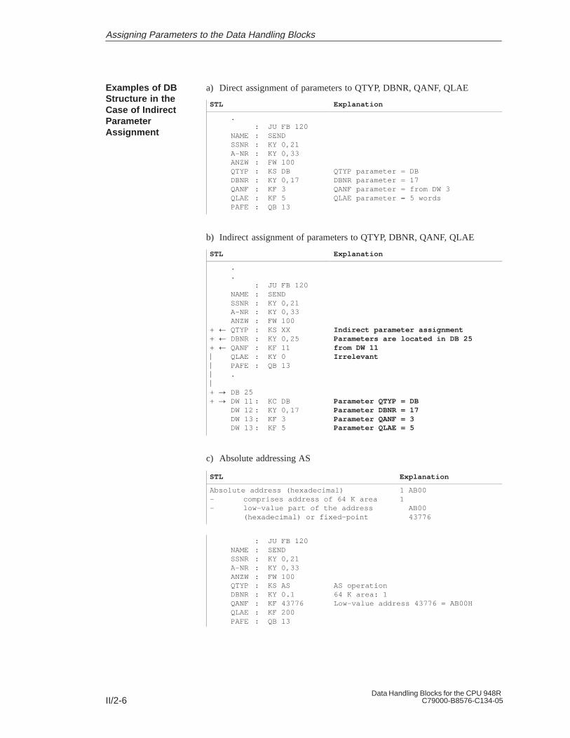
II/2-6Data Handling Blocks for the CPU 948R
C79000-B8576-C134-05
a) Direct assignment of parameters to QTYP, DBNR, QANF, QLAE
STL Explanation
.: JU FB 120
NAME : SENDSSNR : KY 0,21A-NR : KY 0,33ANZW : FW 100QTYP : KS DBDBNR : KY 0,17QANF : KF 3QLAE : KF 5PAFE : QB 13
QTYP parameter = DBDBNR parameter = 17QANF parameter = from DW 3QLAE parameter = 5 words
b) Indirect assignment of parameters to QTYP, DBNR, QANF, QLAE
STL Explanation
.
.: JU FB 120
NAME : SENDSSNR : KY 0,21A-NR : KY 0,33ANZW : FW 100
+ QTYP : KS XX+ DBNR : KY 0,25+ QANF : KF 11 QLAE : KY 0 PAFE : QB 13 .
+ DB 25+ DW 11 : KC DB
DW 12 : KY 0,17DW 13 : KF 3DW 13 : KF 5
Indirect parameter assignmentParameters are located in DB 25from DW 11Irrelevant
Parameter QTYP = DBParameter DBNR = 17Parameter QANF = 3Parameter QLAE = 5
c) Absolute addressing AS
STL Explanation
Absolute address (hexadecimal)– comprises address of 64 K area– low-value part of the address
(hexadecimal) or fixed-point
1 AB001 AB00 43776
: JU FB 120NAME : SENDSSNR : KY 0,21A-NR : KY 0,33ANZW : FW 100QTYP : KS ASDBNR : KY 0.1QANF : KF 43776QLAE : KF 200PAFE : QB 13
AS operation64 K area: 1Low-value address 43776 = AB00H
Examples of DBStructure in theCase of IndirectParameterAssignment
Assigning Parameters to the Data Handling Blocks

II/2-7Data Handling Blocks for the CPU 948RC79000-B8576-C134-05
2.3 Parameter Description
The number of the interface at which the job to be addressed is located (seeSection 1.1 Configuration).
– Parameter type/data type:Data/constant byte(D/KY; KY = 2 bytes)
– Permissible range: 0,0 ... 0,255 (direct parameter assignment)1,0 ... 255,255 –N (indirect parameterassignment)N = Number of words required for indirectparameter assignment
– High byte = 0: Direct parameter assignment; low-order byte = SSNR
– High byte 0: Indirect parameter assignment;low-order byte = pointerr
The job number addressed at the interface. Under the same number, aprogram or a parameter set, through which the function of the CP is defined,is located at the interface.
– Parameter type/data type:Data/constant byte (D/KY)
– Permissible range: 0,0 (”ALL” function)0,1 ... 0,223 (”DIRECT” function)
For the running of the blocks, there is an essential difference between the jobnumber = 0 (an ALL function) and the job number 0. This operatingmode is called DIRECT function (not to be confused with direct parameterassignment).
Address of the condition codeword in which either the processing of the jobspecified under A-NR will be indicated to the user (DIRECT functions) or ajob number (ALL functions).
– Parameter type/data type:Input/word (I/W)
– Permissible range: FW 0 ... 252DW 0 ... 254
With direct parameter assignment, DW refers to the DB/DX data blockspecified before the data handling block call. For indirect parameterassignment, see above.
The data blocks must be of sufficient length. If, for example, the ANZWaddress is DW 7, then the DB/DX block must be at least 14 words long(5 words for block header, DW 0 to DW 8), so that a possible subsequentANZW (see below) can be processed.
The blocks which write to the condition codeword and the method ofevaluating the latter are described in detail in Section 2.5 ”Evaluating theOutput Parameters”.
SSNR:Interface Number
A-NR:Job Number
ANZW: ConditionCodeword
Assigning Parameters to the Data Handling Blocks

II/2-8Data Handling Blocks for the CPU 948R
C79000-B8576-C134-05
The maximum number of bytes which can be transferred by one SEND orRECEIVE block is called the frame size. If the quantity of data to beexchanged is greater than the frame size, as many blocks must be called asare necessary to complete the transfer.
On startup of the programmable controller, the frame size between theprocessor and the interface is decided by SYNCHRON. The frame size canbe influenced by the BLGR parameter (see SYNCHRON block description).
– Parameter type/data type:Data/byte (D/KY)
– Permissible range : 0,0 ... 0,255
The following frame sizes can be set:
0 Frame with max. 256 bytes 1)
1 Frame with max. 16 bytes
2 Frame with max. 32 bytes
3 Frame with max. 64 bytes
4 Frame with max. 128 bytes
5 Frame with max. 256 bytes
6 Frame with max. 512 bytes
7..
254 Frame with max. 256 bytes 2)
255 Frame fixed at 512 bytes
1) Default for CPU 948; the block execution time is thus less than 10 ms (acknowledgement time not taken into account)
2) Corresponds to parameter assignment with frame size ”0”.
Increasingblockexecutiontime
Increasingnumber ofblock calls
The PAFE byte (flag byte, output byte or input byte) indicates whenproblems occur in processing a data handling block. When evaluating thisparameter, indication of the (transitory or permanent) interface status (e.g.interface overloaded, not ready) must be distinguished from indication of”parameter assignment errors”, for example, assignment of illegalparameters to A-NR, QTYP/ZTYP etc. In this case, the parameters assignedof the data handling block and/or the CP (interface) must be changed.
– Parameter type/data type:Output/byte (Q/BY)
– Permissible range: FY 0 ... FY 255QB 0 ... QB 127 (if present)IB 0 ... IB 127 (if present)
BLGR:Frame Size
PAFE:Error Indication inthe Event ofParameterAssignment Errors
Assigning Parameters to the Data Handling Blocks

II/2-9Data Handling Blocks for the CPU 948RC79000-B8576-C134-05
7 6 5 4 3 2 1 0
Error identification1 = Error0 = No error
Error number:0 = No error1 ... F = Error (hexadecimal)
Always deletedby the data handling blockwhen PAFE byte iswritten to
The error numbers are described in detail in Section 2.5 ”Evaluating theOutput Parameters”.
PAFE ByteStructure
Assigning Parameters to the Data Handling Blocks

II/2-10Data Handling Blocks for the CPU 948R
C79000-B8576-C134-05
2.4 Source and Destination Parameters (Q/ZTYP, DBNR, Q/ZANF andQ/ZLAE)
The term ”source parameter” covers the following parameters:
Table 2-1 Structure of the Source Parameter
Parameter Meaning Example
QTYP Source type DB
DBNR Data block numberor: 64K memory area in AS mode
(DB) 17
QANF Source start (DW) 3
QLAE Source length 5 (DW)
These parameters identify an area. This area forms a data source; that is, thedata of this area are transferred (copied) to the interface.
QTYP/DBNR = DB17
Block header(5 words)
DW0
DW1
DW2
DW3
DW4
DW5
DW6
DW7
DW8
DW9
QANF = DW3
QLAE = 5 DW
SourceParameters: QTYP,QANF, QLAE
Example
Assigning Parameters to the Data Handling Blocks

II/2-11Data Handling Blocks for the CPU 948RC79000-B8576-C134-05
The term ”destination parameter” covers the following parameters:
Table 2-2 Structure of the Destination Parameter
Parameter Meaning Example
ZTYP Destination type DX
DBNR Data block numberor: 64K memory area in AS mode
(DX) 18
ZANF Destination start (DW) 3
ZLAE Destination length 5 (DW)
These four parameters identify an area. This area forms a data sink; that is, itreceives data supplied from the interface. Do not forget that in this processthe ”old” data are overwritten.
ZTYP/DBNR = DX 18
Block header(5 words)
DW0
DW1
DW2
DW3
DW4
DW5
DW6
DW7
DW8
DW9
ZANF = DW 3
ZLAE = 5 DW
See Section 3.4 ”Memory Organization, Area Limits” for furtherinformation.
DestinationParameters: ZTYP,ZANF, ZLAE
Example
Assigning Parameters to the Data Handling Blocks

II/2-12Data Handling Blocks for the CPU 948R
C79000-B8576-C134-05
With this parameter, the type of data source (with SEND block) or type ofdata destination (with RECEIVE and FETCH blocks) can be specified bymeans of ASCII characters.
– Parameter type/data type:Data/constant character(D/KY; KS = 2 ASCII characters)
– Permissible area: DB, DX, ZB, TB, BS, AS (direct parameter assignment, word areas)MB, AB, EB, PB (direct parameter assignment, byte areas)XX (indirect parameter assignment)RW (READ/WRITE),NN (source/destination parameters of CP)
If an XX, RW, DB or DX identifier is specified for QTYP/ZTYP, the datahandling block must be informed of the data block required in the low-orderbyte of this parameter.
– Parameter type/data type:Data/constant byte(D/KY; KS = 2 bytes)
– Permissible area: 0,3 ... 0,255 (with direct parameterassignment, high-order byte must be 0)0,3... 255,255 (with indirect parameter assignment and READ/WRITE)if high-order byte = 0: DB data blockif high-order byte 0: DX data block)
If, with QTYP, AS is assigned as the type of data source or data destination,the number of the 64K memory area should then be specified as a parameterfor DBNR (see Section 3.4).
Start address (relative to area start) of the source/destination frame withdirect parameter assignment.
Using the XX (indirect parameter assignment) and RW (READ/WRITE) typeidentifiers, the DW numbers from which the parameters start can be specifiedhere.
– Parameter type/data type:Data/constant fixed point (D/KF)
– Permissible areafor CPU 948: 0 ... 65535
Note:With the KF data format, the programmer accepts any value between –32768and +32767. QANF/ZANF is considered by the handling block as anunsigned (positive) number between 0 and 65535 (corresponds to0000H...FFFFH).
QTYP/ZTYP:Type of DataSource/DataDestination
DBNR:DB Number withDB, DX, XX, RWType Identifiers
QANF/ZANF:Start Address oftheSource/DestinationData Frame
Assigning Parameters to the Data Handling Blocks

II/2-13Data Handling Blocks for the CPU 948RC79000-B8576-C134-05
Depending on the source/destination type, the information is understood to bein bytes or in words.
– Parameter type/data type:Data/constant fixed point (D/KF)
– Permissible area: 1 ... 32767, –1
The ”joker length” (QLAE, ZLAE = –1) means:
In the case of RECEIVE, that as much data is accepted as the interfaceprovides
In the case of SEND, that as much data is transferred to the interface asthe area permits (transmission up to the limit of the area).
The meaning and relationships between the source/destination parameters arelisted in the table below:
Table 2-3 Meaning and Relationships of the Source/Destination Parameters; Word Areas (1)
QTYP/ZTYPDescription
DBSource/destination data
from/to data block
DXSource/destination datafrom/to DX data block
ZBSource/destination data
from/to counters
DBNRMeaning
Permissible area CPU 948
DB from which the sourcedata are taken or into whichthe destination data aretransferred3 ... 255
DX from which the sourcedata are taken or to whichthe destination data aretransferred3 ... 255
Irrelevant
QANF/ZANFMeaning
Permissible area CPU 948
DW number starting fromwhich data are read orwritten
0 ... 4090
DW number starting fromwhich data are read orwritten
0 ... 4090
Number of counter startingfrom which data are read orwritten
0 ... 255
QLAE/ZLAEMeaning
Permissible area CPU 948
Length of thesource/destination frame inwords
1 ... 4091
Length of thesource/destination frame inwords
1 ... 4091
Length of the source/destination frame in words(1 counter = 1 word)
1 ... 256
QLAE/ZLAE:Length of theSource/DestinationFrame
Assigning Parameters to the Data Handling Blocks

II/2-14Data Handling Blocks for the CPU 948R
C79000-B8576-C134-05
Table 2-4 Meaning and Relationships of the Source/Destination Parameters; Word Areas (2)
QTYP/ZTYPDescription
TBSource/destination data
from/to timers
BS Source/destination datafrom/to system data area
ASSource/destination data
from/to absolute addressedmemory locations
DBNRMeaningPermissible area CPU 948
Irrelevant
–
Irrelevant
–
64 K area address
0.0 ... 0.13
QANF/ZANFMeaning
Permissible area CPU 948
Number of timer starting from which thedata are read or written
0 ... 255
Number of RS word starting from which thedata are read or written
0 ... 255
Absolute start address start-ing from which data areread or written0 ... FFFF (hex.) or0 ... 65535 (fixed-pointdec.)
QLAE/ZLAEMeaning
Permissible area CPU 948
Length of the source/destination frame in words(1 timer = 1 word)
1 ... 256
Length of the source/destination frame in words(1 system data item =1 word)1 ... 256
Length of the source/destination frame in words(1 counter = 1 word)
1 ... 32767
See Section 3.4 ”Area Limits” for further information.
Table 2-5 Meaning and Relationships of the Source/Destination Parameters; Word Area
QTYP/ZTYP
Description
MB
Source/destination datafrom/to flag area
AB
Source/destination datafrom/to process imageof the outputs (PIQ)
EB
Source/destinationdata from/to processimage of the inputs
(PII)
PB
Source/destination datafrom/to I/O modules,if source data: input
modules, if destinationdata: output modules
DBNR Irrelevant Irrelevant Irrelevant Irrelevant
QANF/ZANFMeaning
Permissiblearea CPU 948
Flag byte numberstarting from whichdata are read or written0 ... 255
Output byte numberstarting from whichdata are read or written0 ... 127
Input byte numberstarting from whichdata are read or written0 ... 127
I/O byte numberstarting from whichdata are read or written.
0 ... 127 dig. I/O, 128 ... 255 dig. oranalog I/O
QLAE/ZLAEMeaning
Permissiblearea CPU 948
Length of thesource/destinationframe in bytes1 ... 256
Length of thesource/destinationframe in bytes1 ... 128
Length of thesource/destinationframe in bytes1 ... 128
Length of thesource/destinationframe in bytes1 ... 256
Assigning Parameters to the Data Handling Blocks

II/2-15Data Handling Blocks for the CPU 948RC79000-B8576-C134-05
Table 2-6 Meaning and Relationships of the Source/Destination Parameters; Special Cases
QTYP/ZTYP
Meaning
XX
Indirect parameter assignment;Source or destination
parameters are stored in theDB or DX data block
(specified by DBNR andQANF)
RW
READ/WRITE;Source or destination
parameters are stored in the DBor DX data block (specified by
DBNR and QANF)
NN
No source/destinationparameters in block;
parameters can be suppliedby interface
DBNRMeaning
Permissiblearea CPU 948
DB/DX in which thesource/destination parametersare stored; DB if high-orderbyte = 0 otherwise DX
1 ... 255
DB/DX in which thesource/destination parametersare stored; DB if high-orderbyte = 0 otherwise DX
1 ... 255
Irrelevant
QANF/ZANFMeaning
Permissiblearea CPU 948
DW number starting fromwhich the parameters are stored
0 ... 32767
DW number starting fromwhich the parameters are stored
0 ... 32767
Irrelevant
QLAE/ZLAE Irrelevant Irrelevant Irrelevant
See Section 3.4 Area Limits for further information.
Assigning Parameters to the Data Handling Blocks
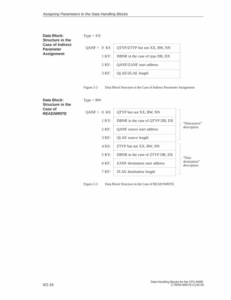
II/2-16Data Handling Blocks for the CPU 948R
C79000-B8576-C134-05
Type = XX
QANF + 0 KS
1 KY:
2 KF:
3 KF:
QTYP/ZTYP but not XX, RW, NN
DBNR in the case of type DB, DX
QANF/ZANF start address
QLAE/ZLAE length
Figure 2-2 Data Block Structure in the Case of Indirect Parameter Assignment
Type = RW
QANF + 0 KS
1 KY:
2 KF:
3 KF:
4 KS:
5 KY:
6 KF:
7 KF:
QTYP but not XX, RW, NN
DBNR in the case of QTYP DB, DX
QANF source start address
QLAE source length
ZTYP but not XX, RW, NN
DBNR in the case of ZTYP DB, DX
ZANF destination start address
ZLAE destination length
”Data source”description
”Datadestination”description
Figure 2-3 Data Block Structure in the Case of READ/WRITE
Data Block:Structure in theCase of IndirectParameterAssignment
Data Block:Structure in theCase ofREAD/WRITE
Assigning Parameters to the Data Handling Blocks

II/2-17Data Handling Blocks for the CPU 948RC79000-B8576-C134-05
2.5 Evaluating the Output Parameters
PAFE is purely an output parameter, whereas RLO and ANZW are both inputand output parameters. The following graphical representation shows in whatway and in what context the data handling blocks influence the outputparameters.
Output parameters RLO, PAFE, ANZW
IF no error occurred
RLO:RLO = 0
RLO:RLO = 1
PAFE:”Error/no error” IDhas been setError number 0
PAFE:”Error/no error” ID deleted
Error number = 0 (i.e. no error)
ANZW:The condition codeword(s)has/have been deleted/written toaccording to the description
IF PAFE byte can be written to
ELSETHEN
THEN ELSE
Figure 2-4 Influence of the Data Handling Blocks on the Output Parameters
If the condition accompanying ”IF” is fulfilled, then the column under”THEN” is valid. If it is not fulfilled, the ”ELSE” column is valid, etc.
If an error has occurred, the condition codeword is irrelevant.
If an error occurs during the data handling block routine (this can be an”actual” parameter assignment error, or other type of error 1), the RLO is set.If no error occurs, RLO is reset (deleted). A quick error analysis cantherefore be carried out following the function block 2).
Error indication by means of RLO always takes place. The PAFE byte canonly then be written to if the PAFE (actual) parameter is permissible.
1) Note: A typical parameter assignment error is, for example, a job numbergreater than the permissible maximum. If the CP is not ready tocommunicate (”interface overloaded”, ”interface reserved by otherprocessor”), this, as well as other errors connected with the CP, will berecognized as an error and indicated with an error number in the PAFEbyte.
Output Parameters:RLO, PAFE, ANZW
Parameters:PAFE and RLO
Assigning Parameters to the Data Handling Blocks

II/2-18Data Handling Blocks for the CPU 948R
C79000-B8576-C134-05
2) Note: No error has occurred if handshake signals are not exchanged (1-4)or if a handshake is broken off (5, 6) for any of the following reasons:
1. RLO (RLO ”input parameter” not to be confused with RLO”output parameter” (= error indicator)) = 0
2. Job is already/still running (SEND/FETCH direct)
3. RECEIVE job is not (yet) ready (RECEIVE direct)
4. This function does not include a handshake (CONTROL)
5. Data transfer/reception is disabled
6. Only parameters are to be passed, etc.
It follows, therefore, that, in these cases too, no error numbers are defined inthe PAFE byte. The individual block descriptions provide information as towhich of these six situations may be applicable.
7 6 5 4 3 2 1 0
Error identification1 = Error0 = no error
Error number:0 = no error1 ... F = Error (hexadecimal)
Always deleted by thedata handling block when PAFEbyte is written to
Table 2-7 Meaning of the Error Numbers in the PAFE Byte
ErrorNo.
(hex.)Meaning
0 No error
1–F Error
1–4 Error in source/destination parameter (QTYP/ZTYP, DBNR, QANF/ZANFor QLAE/ZLAE) orpointer to source/destination parameter incorrect with QTYP/ZTYP XX andRW, (XX = indirect parameter assignment, RW = READ/WRITE) orerror in source/destination parameter from CP
1 Source/destination formally incorrect– QTYP/ZTYP illegal– DBNR data block number greater than 255; that is, high byte 0– QLAE/ZLAE length illegal, permissible length: 1...32767 and –1.
2 DB or DX data block does not exist or is not permissible; (for example: DB0,DX0; in the case of QTYP/ZTYP DB, DX, XX, RW).
Structure:PAFE Byte
Assigning Parameters to the Data Handling Blocks

II/2-19Data Handling Blocks for the CPU 948RC79000-B8576-C134-05
ErrorNo.
(hex.)Meaning
3 Area too small or sum of start address (QANF/ZANF) and length(QLAE/ZLAE) too great (with all QTYP/ZTYP).
4 Area does not exist or is not permissible (with QTYP/ZTYP, AS,AB, EB, PB).
5 (Address of) condition codeword incorrect
6 No. not reserved
7 Interface does not exist
8 Interface not ready
9 Interface overloaded
A Interface reserved by other processor (multiprocessor operation)
B Job number illegal or frame size (SYNCHRON) illegal
C Interface does not respond or interface does not respond in time orinterface rejects job (negative handshaking acknowledgement).
D Other interface errors, including– Error (or illegal acknowledgement) in handshaking
acknowledgement– Frame size of interface not permissible– Synchronization running (no error)
E Other data handling block, errors including– No data block selected with indirect assignment of
parameters to the SSNR, A-NR, ANZW, BLGR– If PAFE is assigned EB or AB and does not exist
F FB call not permissible, including– Double call when interrupts can occur between statements.
Note:If the ”Status” bit is set in the condition codeword ANZW and the identifier”Job completed with error” (bit 23 = 1) is set, an error number has beenwritten in the bits 28 to 211. This error number corresponds to that of thePAFE byte as follows:
1 ... 5 These error numbers and their meanings are identical in the PAFEbyte and ANZW:The interface stores the number received from the data handlingblock in the job status without carrying out any change. After thecorresponding parameters have been assigned, the job status iscopied into the condition codeword by the next data handling blockcalled.
6 ... F The meaning of these numbers in the PAFE byte, as it is describedhere, is not identical to the numbering in the job statuses. The CPdescriptions contain specific error lists.
Assigning Parameters to the Data Handling Blocks

II/2-20Data Handling Blocks for the CPU 948R
C79000-B8576-C134-05
The jobs identified by a job number constitute the management unit of aninterface (or of the CPs).
The corresponding assignment on the handling block
is indicated by the A-NR parameter(SEND/RECEIVE/FETCH/CONTROL/RESET direct)
is produced by the flagging of a job number in the ANZW(SEND/RECEIVE/CONTROL ALL)
In the interface, there is a job status for every job. The status is managed bythe interface and it indicates whether a job is (still) running in the CP orwhether it has been completed by the CP without any errors or with aparticular error. Occupation of the condition codeword with ”status” (seebelow) means, among other things, that this job is copied into the ANZW.
The STEP 5 program in the CPU should be structured so that a particularcondition codeword is allocated to each defined job.
In this way, an image of the activities in the interface or in the CP can beobtained in the CPU. This can only take place if the condition codewords areregularly updated by calling suitable data handling blocks (see blockdescription, for example, CONTROL, SEND direct when idling).
You must distinguish between the ANZW 1 and ANZW 2 parameters.
Furthermore, do not forget that when ANZW 1 is occupied with ”status”, itwill be used both as an input parameter (bit 27 = 1: data transfer/receptiondisabled!) and as an output parameter.
1. The condition codeword(s) will basically only be written to (changed) ifno error has occurred while the data handling block was being processed.In this case, the condition codewords will be written to according to thefollowing table:
Table 2-8 Assignments of the Condition Codewords
Function ANZW 1 ANZW 2
SEND/REC. DIRECT
SEND/REC. ALL
FETCH (DIRECT)
CONTROL DIRECT
CONTROL ALL
Status
Job no.
Status
Status
Job no.
Quantity
–
–
–
–
2. ANZW 1 and ANZW 2 (with SEND/REC DIRECT) is always written to(if no error has occurred).
Parameter: ANZW
Rules for Writingto ANZW by theDHB
Assigning Parameters to the Data Handling Blocks
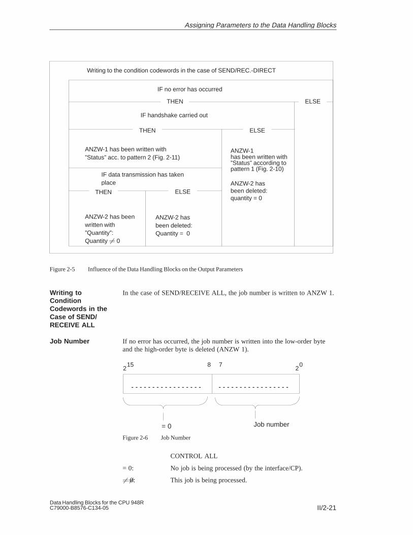
II/2-21Data Handling Blocks for the CPU 948RC79000-B8576-C134-05
ANZW-2 has beenwritten with”Quantity”:Quantity 0
Writing to the condition codewords in the case of SEND/REC.-DIRECT
IF no error has occurred
THEN ELSE
IF handshake carried out
THEN ELSE
ANZW-1 has been written with”Status” according topattern 1 (Fig. 2-10)
ANZW-2 hasbeen deleted:quantity = 0
ANZW-1 has been written with”Status” acc. to pattern 2 (Fig. 2-11)
IF data transmission has takenplace
ANZW-2 hasbeen deleted:Quantity = 0
THEN ELSE
Figure 2-5 Influence of the Data Handling Blocks on the Output Parameters
In the case of SEND/RECEIVE ALL, the job number is written to ANZW 1.
If no error has occurred, the job number is written into the low-order byteand the high-order byte is deleted (ANZW 1).
15 8 72
02
= 0 Job number
Figure 2-6 Job Number
CONTROL ALL
= 0: No job is being processed (by the interface/CP).
0: This job is being processed.
Writing toConditionCodewords in theCase of SEND/RECEIVE ALL
Job Number
Assigning Parameters to the Data Handling Blocks

II/2-22Data Handling Blocks for the CPU 948R
C79000-B8576-C134-05
SEND/RECEIVE ALL
= 0 : Idling; that is, no handshake carried out.
1...223: A handshake has been carried out for this job.
= 255: A handshake has been carried out. The CP supplied analternative number instead of the actual job number.
If no data is transmitted and no error has occurred, the ”Quantity” words(ANZW 2) are deleted. If data is transmitted, the quantity word contains thequantity of all the data already transmitted in this job which may beconsiderably more than the quantity of data transmitted by the last datahandling block.
If the ”Data transfer/data reception completed” bit (bits 5 and 6) in ANZW 1is set, ANZW 2 contains the source length or destination length of the job(job number). This is always indicated in bytes.
ANZW 2:
15 8 72
02
Quantity in bytes
Figure 2-7 Quantity of Data to be Transferred
Quantity ofTransmitted Data
Assigning Parameters to the Data Handling Blocks
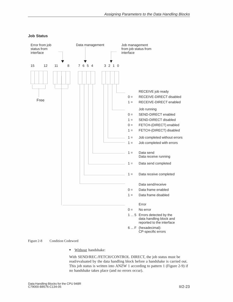
II/2-23Data Handling Blocks for the CPU 948RC79000-B8576-C134-05
7 6 5 4
RECEIVE job ready
0 = RECEIVE-DIRECT disabled
1 = RECEIVE-DIRECT enabledFree
Job running
0 = SEND-DIRECT enabled
1 = SEND-DIRECT disabled
0 = FETCH-(DIRECT) enabled
1 = FETCH-(DIRECT) disabled
1 = Job completed without errors
1 = Job completed with errors
1 = Data sendData receive running
1 = Data send completed
1 = Data receive completed
3 2 1 011 811 815 12
Data send/receive
0 = Data frame enabled
1 = Data frame disabled
Fehler
0 = kein Fehler
1 ... 5 vom Hantierungsbaustein er-kannte und der Schnittstelle gemeldete Fehler
6 ... F (hexadezimal):CP-spezifische Fehler
Error from jobstatus frominterface
Data management Job managementfrom job status frominterface
Error
0 = No error
1 ... 5 Errors detected by thedata handling block andreported to the interface
6 ... F (hexadecimal):CP-specific errors
Figure 2-8 Condition Codeword
Without handshake:
With SEND/REC./FETCH/CONTROL DIRECT, the job status must beread/evaluated by the data handling block before a handshake is carried out.This job status is written into ANZW 1 according to pattern 1 (Figure 2-9) ifno handshake takes place (and no errors occur).
Job Status
Assigning Parameters to the Data Handling Blocks

II/2-24Data Handling Blocks for the CPU 948R
C79000-B8576-C134-05
With handshake:
In the case of all functions where a handshake was initiated (and executedwithout error), the job status will be
– re-read (in the case of DIRECT functions) or
– read for the first time (in the case of ALL functions)
by the data handling block at the end of the handshake.
This updated job status does not have to be evaluated by the data handlingblock. It will be inserted in ANZW 1 according to pattern 2 (Figure 2-10).
Input ANZW:
Input ANZW: Condition codeword before data handling block is called
Output ANZW: Condition codeword after data handling block is called
!
!
OutputANZW:
Job statusfrom interface:
Figure 2-9 Pattern 1
Structure of theConditionCodeword
Assigning Parameters to the Data Handling Blocks

II/2-25Data Handling Blocks for the CPU 948RC79000-B8576-C134-05
Input ANZW:
Input ANZW: Condition codeword before data handling block is called
Output ANZW: Condition codeword after data handling block is called
Data send / receive running 0 0 1
Data send completed 0 1 0Data receive completed 1 0 0No data transmission 0 0 0(e.g.: ”Only parameters passed”,”Data frame disabled”, . . . )
Auxiliary word (status area CP):
Job statusfrom interface:
OutputANZW:
Data frame disabled 1
Data frame enabled 0
Legend:
Figure 2-10 Pattern 2
Assigning Parameters to the Data Handling Blocks

II/2-26Data Handling Blocks for the CPU 948R
C79000-B8576-C134-05
Note:If bit positions 212 to 215 have been deleted following the running of a datahandling block, and if they were set (at least some of them) beforehand, thenthis is an obvious indication that:
1. The handling block was run without any errors (otherwise the conditioncodewords are not written to)
2. A handshake was carried out (otherwise the condition codeword wouldnot be written to according to pattern 2).
Bit positions 24 to 26 now give information about whether data has beentransmitted.
Nibble 1, bits 0 to 3, job management:
The following is encoded here: whether a job has already been started orwhether errors have occurred or whether the job has been disabled.
Important: Each of the bits has a significance of its own. In the case ofseveral CPs, additional significance is assigned to the bit combinations. Forexample, if ”Job running” (bit 2 ) and ”Job completed” (bit 2 or 2 ) are setsimultaneously (contradiction!) in the case of the CP 143, this has thesupplementary meaning of ”CP not ready for this job/job disabled”.
Nibble 2, bits 4 to 7, data management:
The following is encoded here: whether the data transfer for the job is stillrunning or whether the transfer or reception of data has already beencompleted. With bit 7, the data block for the job can be disabled (bit 7 = 1:data block disabled; bit 7 = 0: data block enabled).
Nibble 3, bits 8 to 11, error number:
These are the error indicators of the job. The error indicators are only valid ifthe bit ”Job completed with error” in the first nibble is set at the same time.
Nibble 4, bits 12 to 15, free
a. Bit 0 : RECEIVE job ready (handshake meaningful)
Setting/resetting: By the data handling blocks corresponding to thedeletion condition code in the job status. The bit”RECEIVE job ready” is used with the RECEIVEDIRECT function (received data available).
Evaluation: By the RECEIVE block; the RECEIVE block carriesout the handshake with the interface only if bit 0 is setto 1.
– By the user to query whether or not received data isavailable.
Division of theConditionCodeword
Operation of the”Status” ConditionCodeword
Assigning Parameters to the Data Handling Blocks

II/2-27Data Handling Blocks for the CPU 948RC79000-B8576-C134-05
b. Bit 1 : Job running (SEND/FETCH disabled)
Setting/resetting: By the data handling blocks corresponding to thedeletion condition code in the job status. The ”Jobrunning” bit (= 0) is used with the SEND DIRECT andFETCH DIRECT functions.
Evaluation: By the SEND block and FETCH block. The block willonly carry out the handshake with the interface ifbit 1 = 0; that is, a job will only be assigned if the”old” job has been processed.
– By the user in order to find out whether a ”new” jobcan be initiated.
c. Bit 2 : Job completed without errors
Setting/resetting: By the handling blocks corresponding to the deletioncondition code in the job status.
Evaluation: By the user to check whether the job was completed bythe interface without errors.
d. Bit 3 : Job completed with error
Setting/resetting: By the handling blocks corresponding to the deletioncondition code in the job status.
Evaluation: By the user to check whether the job was completed bythe interface with an error. If the ”Job completed witherror” identifier is set, the reason for the error is to befound in bits 8 to 11 of the condition codeword.
e. Bit 4 : Data transfer/reception running
Setting/resetting: By the SEND and RECEIVE handling blocks. If thetransfer/reception for a job was started (1st subframetransferred) and not yet completed; for example, if datais still to be exchanged via the ALL functions. For thispurpose, the initiation and transmission of the firstsubframe must have been carried out with a DIRECTfunction.
Deleting: By the handling blocks if the condition for setting hasnot been fulfilled.
Evaluation: By the user.During CP-CPU data transmission, you may no longerchange (SEND) or use (RECEIVE) the data frame of ajob.
Assigning Parameters to the Data Handling Blocks

II/2-28Data Handling Blocks for the CPU 948R
C79000-B8576-C134-05
With ”small” data frames, this is not critical since datatransmission here requires only one block call andleads immediately to the condition code ”Data transfercompleted” or ”Data reception completed”. Largerdata frames can, however, only be transmitted insubframes, and this requires several data handlingblock calls. In order to maintain the integrity of thedata, you must first check whether the data frame hasbeen transmitted completely before you change/use thedata of a job. Otherwise, ”old” and ”new” data wouldbe mixed.
f. Bit 5 : Data transfer completed
Setting: By the SEND handling block if the data of a job hasbeen transferred complete to the interface (lastsubframe transmitted).
Resetting: By the handling blocks if the setting condition has notbeen fulfilled. By the user if evaluation has taken place(edge generation).
Evaluation: By the user
With this bit, you can ascertain whether the data for ajob has already been transferred complete to theinterface.
g. Bit 6 : Data reception completed
Setting: By the RECEIVE handling block if the data for a jobhas been received complete by the interface (lastsubframe transmitted).
Resetting: By the handling blocks if the condition for setting hasnot been fulfilled. By the user if evaluation has takenplace (edge generation).
Evaluation: By the user.
With this bit, you can ascertain whether the data of ajob has already been transmitted to the CPU.
h. Bit 7 : Data transfer/reception disabled
Setting: By the user in order to prevent a data frame beingwritten to by the RECEIVE block or being read out bythe SEND block.
Resetting: By the user in order to enable the relevant data frame.
Evaluation: By the SEND and RECEIVE handling blocks onceonly before the first subframe. If bit 27 is set, theblocks do not transfer any data. Instead, they report the”error” to the interface.
i. Bit 8 to 11 : Error number
Setting/resetting: By the handling blocks according to the indicator inthe job status.
Assigning Parameters to the Data Handling Blocks

II/2-29Data Handling Blocks for the CPU 948RC79000-B8576-C134-05
Evaluation: By the user.
The following indicators can appear:
0: No error
1 to 5: CPU or handling block errorThe meanings of the error numbers one to five areidentical to the numbers in the PAFE byte (parameterassignment error).
6 to F : CP or interface error
The error numbers 6 to F (hex.) are CP-specific.
Assigning Parameters to the Data Handling Blocks

II/2-30Data Handling Blocks for the CPU 948R
C79000-B8576-C134-05
Assigning Parameters to the Data Handling Blocks

II/3-1Data Handling Blocks for the CPU 948RC79000-B8576-C134-05
Data Handling Blocks in the User Program
This chapter contains important information for working with data handlingblocks in the user program and for using data blocks in different functions. Italso offers information on determining the area length remaining for datatransfer, the runtime of the data handling blocks, possibilities of reducingruntime and a host of additional information of importance to yourprogramming staff.
3

II/3-2Data Handling Blocks for the CPU 948R
C79000-B8576-C134-05
3.1 Calling Data Handling Blocks
At which points in the program can you call handling blocks? The followingis the simplest course of action:
1. Calling the SYNCHRON block only at initial start and in the cycle.
2. Calling the remaining blocksSEND/SEND-ALL/RECEIVE/RECEIVE-ALL/CONTROL/FETCH/RESET only during cyclic program execution.
3. You can program events that you wish to be deleted duringtime-controlled or event-driven program processing and invoke a datahandling block in such a way that only flags are set to begin with.
During cyclic program execution, the respective data handling blocks willthen be called.
In principle, handling blocks can be called at any point within the userprogram, for example in the warm restart organization block or withintime-controlled execution (OB 13, timed interrupt). However, the followinglimitations must be observed.
The SYNCHRON DHB can only be called conditionally.
The CPU 948R has the following three or four modes of programexecution (among others)
– Cyclic program execution (OB 1, lowest priority)
– Time-controlled program execution (OB 6, OB 9, OB 10 to OB 18,priority is selectable)
– Interrupt-driven program execution (OB 2 to OB 5 or OB 2 to OB 9,priority is selectable) and
– ”Soft STOP” with cyclic execution of communication jobs (OB 39).
The data handling blocks cannot be interrupted. This must be taken intoaccount when calling handling blocks with long runtimes(see Section 3.5).
In ”soft STOP” (OB 39), handling blocks can be called irrespective of thepoint where the interrupt has occurred in RUN mode. For these purposesonly, the required interfaces must have been initialized with a SYNCHRONat CPU restart for the ”soft STOP” (OB 38) status.
Calling DHBs inthe Program
Conditions forCalling DHBs
Data Handling Blocks in the User Program

II/3-3Data Handling Blocks for the CPU 948RC79000-B8576-C134-05
3.2 Calling SEND-ALL and RECEIVE-ALL
For the SEND and RECEIVE blocks, the operating mode SEND-ALL orRECEIVE-ALL can be selected using job number ”0” (see block descriptionin Chapter 4). These blocks permit data transmission to be initiated andcontrolled by the interface.
The SEND-ALL and RECEIVE-ALL functions must be called ”regularly” sothat a request for communication from the interface is detected in time. Forexample, the following options and combinations are available:
Call once (n times) per cycle and per interface (short response times)
Call with a call distributor: in the first cycle for interface 1, in the secondfor interface 2, etc. (low cycle load)
Call within time-controlled execution (OB 13 every 100 ms, independentof cycle time fluctuations)
Call whenever other blocks do not have to be called owing to the process(evenly distributed cycle load and/or assignment of priority to controlactivities over communication)
Call one ALL function after another until the first, second, nth etc. run isnot an idling run. In the next cycle, continue with the following ALLfunction (evenly distributed cycle load).
Data Handling Blocks in the User Program

II/3-4Data Handling Blocks for the CPU 948R
C79000-B8576-C134-05
3.3 Using Data Blocks
The data handling blocks work with up to five DB or DX data blocks in total:
1. A data block which has been assigned the SSNR, A-NR, ANZW andBLGR parameters indirectly. Here, the corresponding data block must beselected before calling the handling block(see Section 2.2 ”Direct and Indirect Parameter Assignment”).
2. a) A data block which has been assigned itssource parameters or destination parameters indirectly(see Section 2.2 ”Direct and Indirect Parameter Assignment”).
b) A data block which, with READ/WRITE, contains the sourceparameters and destination parameters.
3. A data word of a data block can be used as a PLC condition codeword.
4. The data to be transmitted/received may have to be taken from/stored in aDB.
Here, care must be taken to ensure that all data blocks used exist and thatthey are long enough; the use of data blocks comprising more than 256 wordsis possible.
The use of DB 0, DB 1 and DX 0, DX 1 and DX 2 is permitted. If they areused, the handling block rejects them with an error indication.
Data Handling Blocks in the User Program

II/3-5Data Handling Blocks for the CPU 948RC79000-B8576-C134-05
3.4 Memory Organization, Area Limits
The ”area length remaining” is ascertained when executing thesource/destination parameters in the handling block. Here, this means thedifference between the length of an area (DB length, number of flag bytes,for example) and the preset QANF/ZANF start address.
Data block header(5 words)
DW 0
DW 1
DW 2
DW 3
DW 4
QANF/
Area length remaining
= 3 words
The maximum quantity of data to be transmitted must not be greater than thearea length remaining (legality check) or must be oriented to this area lengthremaining (area limit): joker length (joker length: see QLAE/ZLAEparameter); transmission of the length remaining is used by several CPs.
Naturally, the QANF/ZANF start address must exist. In the example (DB 17),the values from 0 to 4 would be permissible.
With all types of area, the rules for procedure set out above apply. Theinformation blocks below contain additional information.
The CPU 948R has 256 counter locations and 256 timer locations:
256 counter locations : C 0 to C 255
256 timer locations : T 0 to T 255
The CPU 948R has 256 system data values in the BS area:
256 system data values : BS 0 to BS 255
With the exception of BS 60 to BS 63, BS data may only be read by the user.BS data should therefore only be assigned the as QTYP parameter. Please seethe Programming Guide for the CPU 948R for more detailed information onthe BS (= system data area RS) data.
Area LengthRemaining
QTYP/ZTYPCounter LocationsZB, TimerLocations TB
QTYPSystem Data AreaBS
Data Handling Blocks in the User Program
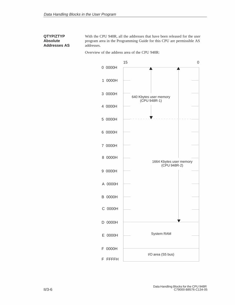
II/3-6Data Handling Blocks for the CPU 948R
C79000-B8576-C134-05
With the CPU 948R, all the addresses that have been released for the userprogram area in the Programming Guide for this CPU are permissible ASaddresses.
Overview of the address area of the CPU 948R:
I/O area (S5 bus)
0 0000H
System RAM
015
1 0000H
3 0000H
4 0000H
1664 Kbytes user memory(CPU 948R-2)
640 Kbytes user memory(CPU 948R-1)
5 0000H
6 0000H
7 0000H
8 0000H
9 0000H
A 0000H
B 0000H
C 0000H
D 0000H
E 0000H
F 0000H
F 0000HF FFFFH
QTYP/ZTYPAbsoluteAddresses AS
Data Handling Blocks in the User Program

II/3-7Data Handling Blocks for the CPU 948RC79000-B8576-C134-05
The position of blocks in the RAM can be changed by means of the”Compress memory” function.
Special care must be taken when using the ”absolute addresses” type. Whenaccessing data blocks, for example, please note that these blocks willdisappear from memory or change their position within memory when
being generated (G DB and GX DX operations)
the memory is compressed (by programmer input or automatically) or
input/updates are carried out on the programmer.
These changes are taken into account ”automatically” by the data handlingblocks when using the ”DB” or ”DX” types. Any errors do not result inillegal areas being accessed, but an error bit is set in the PAFE byte.
The CPU 948R has 256 flag bytes: FY 0 to FY 255
The I/O area (PY) can be an incomplete area (with gaps) since normally notall input and output addresses are assigned or enabled. Example:
QANF/ZANF
Addressnot assigned
Addressnot assigned
Addressnotassigned
Addressnotassigned
IB 0
IB1
IB 3
IB 4
IB 5
IB 6
IB 8
IB 127
QB 0
QB 74
QB 75
QB 76
QB 79
QB 127
QANF/ZANF
arealengthremaining = 2 bytes
Arealengthremaining= 2 bytes
The area length remaining is the number of assigned addresses up to the nextgap.
Note: RI and RJ areas cannot be specified. If these areas are to be transferredby means of data handling blocks, they must be copied into a DB.
QTYP/ZTYPFlags MB
QTYP/ZTYPPIQ/PII (AB/EB)
Data Handling Blocks in the User Program

II/3-8Data Handling Blocks for the CPU 948R
C79000-B8576-C134-05
3.5 Runtime
Runtime withoutHandshake
SEND RE-CEIVE
FETCH RESET CON-TROL
idling
CP in one-sided I/O 0.6 ms 0.7 ms 0.5 ms 0.5 ms 0.5 ms
CP in switched I/O 0.2 ms 0.2 ms 0.2 ms 0.2 ms 0.2 ms
As shown in the table below, the runtime of the data handling blockscomprises up to four components:
1. Basic runtime:
The handling block requires this time, for instance, to prepare datatransmission, update the ANZW, send parameters to, or receiveparameters from, the interface, etc.
These waiting times are interface-dependent (see CP description).However, the handling block aborts the function if the interface does notrespond within a maximum waiting time (PAFE, ”Interface notresponding in time”).
2. Waiting time A
3. Waiting time BWaiting times of the handshake
4. Data transmission time:
This time increases proportionally with the quantity of (net) data to betransferred (see SYNCHRON, parameter BLGR).
Runtime withHandshake
SEND RECEIVE FETCH RESET SYN-CHRON
1. Basic runtime+
2. Waiting time A+
3. Waiting time B+
4. Max. quantityof data to betransferred
xTime per bytein the area:one-sided– MB– EB/AB– DB/DX/ZB/ TB/ASswitched– MB– EB/AB– DB/DX/ZB/ TB/AS
2.3 ms+
0 ... 5 ms
+0 ... 5 ms
512 (bytes)x
15 s30 s 2 s
20 s40 s 4 s
3.0 ms+
0 ... 5 ms
+0 ... 5 ms
512 (bytes)x
35 s65 s 8 s
40 s70 s 9 s
1.6 ms+
0 ... 5 ms
+0 ... 5 ms
1.0 ms+
0 ... 5 ms
+0 ... 5 ms
5.1 ms
0 ... 10 sstartup only
0 ... 10 mscycle only
Runtime withoutHandshake
Runtime withHandshake
Data Handling Blocks in the User Program

II/3-9Data Handling Blocks for the CPU 948RC79000-B8576-C134-05
The table above illustrates that the data handling block user can influence theruntime of SEND and RECEIVE blocks by means of the number of bytes tobe transmitted. The quantity of data required for a job (QLAE/ZLAEparameter) can be reduced when the send/receive data is
checked critically
subjected to reasonable limitations
structured without gaps.
Whereas the QLAE/ZLAE parameters determine the quantity of datarequired for a job, the frame size specifies the maximum quantity of data perblock call to be transmitted by the handshake (see SYNCHRON, BLGRparameter).
The ”efficiency” of a SEND/RECEIVE block; that is, the relation
Data transmission time (4.)
Basic runtime (1.) + Waiting time A (2.) + Waiting time B (3.)
increases with the frame size.
The times listed apply for a one-sided CP plugged into the CC; the timesapply for a switched CP installed 2.5 m from the CC.
”Runtime” is the processing time of data handling blocks.
You can save runtime by observing the following rules:
Direct assignment of the SSNR, A-NR, ANZW and BLGR parameters isfaster than assigning them indirectly.
Direct assignment of the source/destination parameters is faster thanassigning them indirectly (type XX).
The use of data words in DB/DX is considerably faster than using input,output and I/O bytes.
Notes on theRuntime
Data Handling Blocks in the User Program

II/3-10Data Handling Blocks for the CPU 948R
C79000-B8576-C134-05
Data Handling Blocks in the User Program

II/4-1Data Handling Blocks for the CPU 948RC79000-B8576-C134-05
Description: Data Handling Blocks
This chapter contains a representation of every available data handling blockwith block diagram, parameter table and detailed functional description.
4

II/4-2Data Handling Blocks for the CPU 948R
C79000-B8576-C134-05
4.1 SEND Function Block (FB 120)
(1) SSNR
(2) A-NR
(3) ANZW
(4) QTYP
(5) DBNR
(6) QANF
(7) QLAE
SEND
PAFE (8)
Figure 4-1 Block Diagram of the SEND FB
Parameter ParameterType
Data Type Meaning
SSNR D KY Interface number
A-NR D KY Number of the SEND/WRITE job
ANZW I W Condition codeword, indicates theprocessing of the job
QTYP D KS Type of data source (data block, flag, etc.)from which the data is transferred to theinterface.
DBNR D KY Number of the data block in the case ofQTYP DB, DX, XX, RW; 64K areaaddress with QTYP AS
QANF D KF Relative start address of the data source
QLAE D KF Quantity of source data (in bytes orwords)
PAFE Q BY Error bits
The SEND block is used for sending of data and/or parameters from the CPUto the interface. The block has two operating modes:
SEND-ALL
SEND-DIRECT
Function Block
FB 120 Parameters
Function
Description: Data Handling Blocks
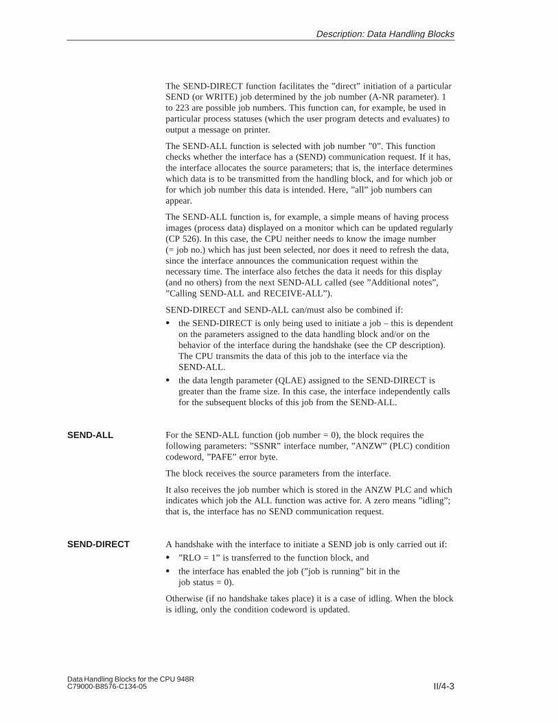
II/4-3Data Handling Blocks for the CPU 948RC79000-B8576-C134-05
The SEND-DIRECT function facilitates the ”direct” initiation of a particularSEND (or WRITE) job determined by the job number (A-NR parameter). 1to 223 are possible job numbers. This function can, for example, be used inparticular process statuses (which the user program detects and evaluates) tooutput a message on printer.
The SEND-ALL function is selected with job number ”0”. This functionchecks whether the interface has a (SEND) communication request. If it has,the interface allocates the source parameters; that is, the interface determineswhich data is to be transmitted from the handling block, and for which job orfor which job number this data is intended. Here, ”all” job numbers canappear.
The SEND-ALL function is, for example, a simple means of having processimages (process data) displayed on a monitor which can be updated regularly(CP 526). In this case, the CPU neither needs to know the image number(= job no.) which has just been selected, nor does it need to refresh the data,since the interface announces the communication request within thenecessary time. The interface also fetches the data it needs for this display(and no others) from the next SEND-ALL called (see ”Additional notes”,”Calling SEND-ALL and RECEIVE-ALL”).
SEND-DIRECT and SEND-ALL can/must also be combined if:
the SEND-DIRECT is only being used to initiate a job – this is dependenton the parameters assigned to the data handling block and/or on thebehavior of the interface during the handshake (see the CP description).The CPU transmits the data of this job to the interface via theSEND-ALL.
the data length parameter (QLAE) assigned to the SEND-DIRECT isgreater than the frame size. In this case, the interface independently callsfor the subsequent blocks of this job from the SEND-ALL.
For the SEND-ALL function (job number = 0), the block requires thefollowing parameters: ”SSNR” interface number, ”ANZW” (PLC) conditioncodeword, ”PAFE” error byte.
The block receives the source parameters from the interface.
It also receives the job number which is stored in the ANZW PLC and whichindicates which job the ALL function was active for. A zero means ”idling”;that is, the interface has no SEND communication request.
A handshake with the interface to initiate a SEND job is only carried out if:
”RLO = 1” is transferred to the function block, and
the interface has enabled the job (”job is running” bit in the job status = 0).
Otherwise (if no handshake takes place) it is a case of idling. When the blockis idling, only the condition codeword is updated.
SEND-ALL
SEND-DIRECT
Description: Data Handling Blocks

II/4-4Data Handling Blocks for the CPU 948R
C79000-B8576-C134-05
In the cyclic program, process statuses are evaluated, and influence the RLO.A SEND-DIRECT function is then called unconditionally (JU FB).Consequently, the result of the logic operation ”switches” the handshake onor off. Whatever the situation, a current copy of the job status exists in theANZW.
For the SEND-DIRECT function, the block first requires the SSNR, A-NR( 0), ANZW and PAFE parameters. The block only requires the sourceparameters if a handshake is included. The SEND function is performed indifferent ways, depending on the parameters assigned to the block:
If the interface can take the data, the SEND block transmits all the data tothe interface.
However, if the interface signals that it only requires the parameters ofthe job, only the source parameters will be transferred to the interface. Ifthe quantity of data to be transferred is greater than the declared framesize, only the parameters will be transferred to the interface with the firstdata frame.
The interface requests the data or the subsequent frames of this job fromthe processor via the SEND-ALL function.
If the ”NN” identifier is entered in the QTYP parameter, the blockaccepts the source parameters from the interface, and transmits all thedata or the first subframe. If the interface does not supply a set ofparameters, it is a case of ”job initiation without data transfer”.
Assigning parameters with QTYP = ”RW” is called ”WRITE”.SEND-DIRECT transmits the source and destination parameters as wellas the address of the condition codeword to the interface. The interfacefetches the source data via SEND-ALL.
In the case of the CP 143, the destination parameters, together with thedata, are transmitted to the communication partner, which stores them asdestination data at the position specified by the destination parameters(see the CP description).
Typical Application
Description: Data Handling Blocks

II/4-5Data Handling Blocks for the CPU 948RC79000-B8576-C134-05
4.2 SEND-A Function Block (FB 126)
(1) SSNR
(2) A-NR
(3) ANZW
SEND-A
PAFE (8)
Figure 4-2 Block Diagram of the SEND-A FB
Parameter ParameterType
Data Type Meaning
SSNR D KY Interface number
A-NR D KY Job number: always 0
ANZW I W Condition codeword: indicates processingof the job.
PAFE Q BY Parameter assignment error: error indicators
The SEND-A function block differs from the SEND function block by nothaving the QTYP, DBNR, QANF and QLAE parameters.
Whenever these parameters are irrelevant, the user of this block saves storagespace as well as desk work and makes programs more transparent.
Further differences with reference to functionality or runtime do not exist.
Function Block
FB 126 Parameters
Function
Description: Data Handling Blocks
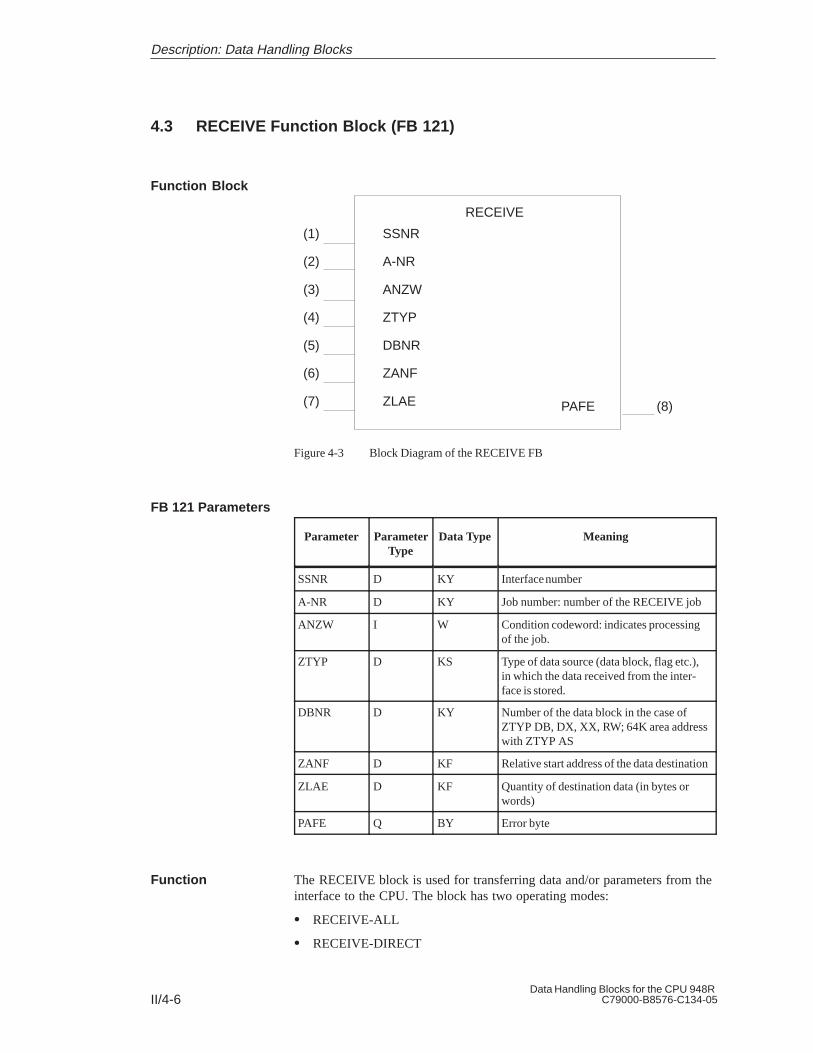
II/4-6Data Handling Blocks for the CPU 948R
C79000-B8576-C134-05
4.3 RECEIVE Function Block (FB 121)
(1) SSNR
(2) A-NR
(3) ANZW
(4) ZTYP
(5) DBNR
(6) ZANF
(7) ZLAE
RECEIVE
PAFE (8)
Figure 4-3 Block Diagram of the RECEIVE FB
Parameter ParameterType
Data Type Meaning
SSNR D KY Interface number
A-NR D KY Job number: number of the RECEIVE job
ANZW I W Condition codeword: indicates processingof the job.
ZTYP D KS Type of data source (data block, flag etc.),in which the data received from the inter-face is stored.
DBNR D KY Number of the data block in the case ofZTYP DB, DX, XX, RW; 64K area addresswith ZTYP AS
ZANF D KF Relative start address of the data destination
ZLAE D KF Quantity of destination data (in bytes orwords)
PAFE Q BY Error byte
The RECEIVE block is used for transferring data and/or parameters from theinterface to the CPU. The block has two operating modes:
RECEIVE-ALL
RECEIVE-DIRECT
Function Block
FB 121 Parameters
Function
Description: Data Handling Blocks

II/4-7Data Handling Blocks for the CPU 948RC79000-B8576-C134-05
The RECEIVE-DIRECT function facilitates the ”direct” initiation of aparticular RECEIVE job determined by the job number (A-NR). 1 to 223 arepossible job numbers. This function can, for example, be used to transmitdata from an intelligent I/O module to the CPU (cf. IP 252 closed-loopcontrol module).
The RECEIVE-ALL function is selected with job number ”0”. This functionchecks whether the interface has a (RECEIVE) communication request. If ithas, the interface allocates the destination parameters; that is, the interfacedetermines where data received from the handling block is to be stored andfor which job or for which job number this data is intended. ”All” jobnumbers can appear here.
The RECEIVE-ALL function is, for example, a simple means of transmittinginput values (from a monitor with a keyboard) to the CPU. In this case, theCPU neither needs to know the image mask (= job no.) which has just beenselected, nor whether input values are available or when they will beavailable, since the interface announces the communication request onlywhen needed and the next RECEIVE-ALL called transmits the values to theCPU.
RECEIVE-DIRECT and RECEIVE-ALL can/must be combined if:
the RECEIVE-DIRECT is only being used to initiate a job. This dependson the handling block parameter assignment and/or on the behavior of theinterface during the handshake (cf. CP description). The data of this jobwill be transmitted from the interface to the CPU by means of theRECEIVE-ALL.
the data length parameter (ZLAE) assigned to the RECEIVE-DIRECT isgreater than the frame size. In this case, the interface independentlysupplies the subsequent frames of this job via the RECEIVE-ALL.
Owing to the runtime, only the data which is already in the CP can betransmitted by the RECEIVE function to the CPU.
Data which first must be requested by the CP via a bus link or which must begenerated in some other way, is transmitted to the CPU by the combinedaction of the FETCH (see block description) and the RECEIVE-ALLfunction.
For the RECEIVE-ALL function (job number = 0), the block requires thefollowing parameters: ”SSNR” interface number, ”ANZW” (PLC) conditioncodeword, ”PAFE” error byte.
The block receives the destination parameters from the interface. It alsoreceives the job number, which is stored in the ANZW-PLC, and indicateswhich job the ALL function was active for. A zero means ”idling”; that is,the interface had no RECEIVE communication request.
RECEIVE-ALL
Description: Data Handling Blocks

II/4-8Data Handling Blocks for the CPU 948R
C79000-B8576-C134-05
A handshake with the interface to initiate a RECEIVE job is only carried outif:
”RLO = 1” is transferred to the function block, and
the interface has enabled the job (”RECEIVE job ready” bit in the jobstatus = 1).
Otherwise (if no handshake takes place) it is a case of idling. When the blockidling, only the condition codeword is updated.
If a RECEIVE-DIRECT function is called unconditionally (JU FB), the resultof the logic operation ”switches” the handshake on or off. In any case, acurrent copy of the job status exists in the condition codeword.
For the RECEIVE-DIRECT function, the block first requires the SSNR,A-NR ( 0), ANZW and PAFE parameters. Only if a handshake is starteddoes block require the destination parameters. The RECEIVE functionperforms in different ways, depending on the parameters assigned to theblock:
If the interface can provide the data, the RECEIVE block transmits all thedata to the CPU. However, if (1) the interface signals that it only requiresthe parameters of the job, or if (2) the quantity of data to be transferred isgreater than the declared frame size, only the destination parameters willbe transferred to the interface. In the second case, the first data frame willalso be accepted.
The data or the subsequent frames of this job are transferred by theinterface to the processor by means of the RECEIVE-ALL function. Theparameters remain the same in any case for the user of the blocks. Onlythe time of data transfer is delayed in the cases just mentioned.
If the ”NN” identifier is written to the ZTYP parameter, the blockreceives the destination parameters from the interface, and transmits allthe data or the first subframe. If the interface does not supply a set ofparameters, it is a case of ”job initiation without data transfer”.
The assignment of parameters with ZTYP = ”RW”, (READ/WRITE) ismeaningless with the RECEIVE function and is not permissible.
RECEIVE-DIRECT
Description: Data Handling Blocks

II/4-9Data Handling Blocks for the CPU 948RC79000-B8576-C134-05
4.4 REC-A Function Block (FB 127)
(1) SSNR
(2) A-NR
(3) ANZW
REC-A
PAFE (8)
Figure 4-4 Block Diagram of the REC-A FB
Parameter ParameterType
Data Type Meaning
SSNR D KY Interface number
A-NR D KY Job number: always 0
ANZW I W Condition codeword: indicates processingof job.
PAFE Q BY Parameter assignment error: error byte
The REC-A function block differs from the RECEIVE function block by nothaving the ZTYP, DBNR, ZANF and ZLAE parameters.
In cases where these parameters are irrelevant, the use of this block savesstorage space as well as desk work and makes programs more transparent.
Further differences with reference to the functionality or runtime do not exist.
Function Block
FB 127 Parameters
Function
Description: Data Handling Blocks

II/4-10Data Handling Blocks for the CPU 948R
C79000-B8576-C134-05
4.5 FETCH Function Block (FB 122)
(1) SSNR
(2) A-NR
(3) ANZW
(4) ZTYP
(5) DBNR
(6) ZANF
(7) ZLAE
PAFE (8)
Figure 4-5 FETCH Function Block (FB 122)
Parameter ParameterType
Data Type Meaning
SSNR D KY Interface number
A-NR D KY Job number: always 0
ANZW I W Condition codeword: indicates processingof job.
ZTYP D KS Type of data destination (data block, flag,etc.) in which data transferred from theinterface is stored.
DBNR D KY Number of the data block in the case ofZTYP, DB, DX, XX, RW; 64K area addressin the case of ZTYP AS
ZANF D KF Relative start address of the data destination
ZLAE D KF Quantity of destination data (in bytes orwords)
PAFE Q BY Parameter assignment error: error byte
The FETCH block initiates a fetch job. This gives the CPU access to datawhich is not in the CP, but which must first be generated/acquired by the CP,for example, from another programmable controller by means of a bus link.
The FETCH block has only one operating mode:
FETCH-DIRECT
1 to 223 are possible job numbers.
Function Block
FB 122 Parameters
Function
Description: Data Handling Blocks

II/4-11Data Handling Blocks for the CPU 948RC79000-B8576-C134-05
By transferring the job number, the destination parameters and the conditioncodeword address, the FETCH block informs the interface of the datarequired (job number), where this data is to be stored in the CPU (destinationparameters) and which condition codeword this is to be indicated in. As soonas the data requested is in the CP, the interface provides the RECEIVE-ALLfunction with the parameters and the data. The FETCH block itself does nottransmit/receive any data.
The handshake with the interface is only carried out if:
”RLO = 1” has been transferred to the function block, and
the interface has enabled the job (”job running” bit in the job status = 0).
Otherwise (if no handshake takes place) it is a case of idling. When the blockis idling, only the condition codeword is updated.
If a FETCH-DIRECT function is called unconditionally (JU FB), the result ofthe logic operation ”switches” the handshake on or off. In any case, a currentcopy of the job status exists in the condition codeword.
For the FETCH-DIRECT function, the block first requires the SSNR, A-NR( 0), ANZW and PAFE parameters. Only if a handshake is started does theblock require the destination parameters. The FETCH function executes indifferent ways, depending on the parameters assigned to it:
If the ”NN” identifier is written into the ZTYP parameter, this is a case of”job initiation without parameter passing.”
The assignment of parameters with ZTYP = ”RW” is referred to as”READ”.
In the case of the CP 143, this parameter assignment allows a READ jobto be initiated (see the CP description).
The FETCH block transmits the source parameters and destinationparameters as well as the address of the condition codeword to the interface.”Later”, the interface transfers the data requested to the RECEIVE-ALL,which stores it at the position specified by the destination parameters.
Description: Data Handling Blocks
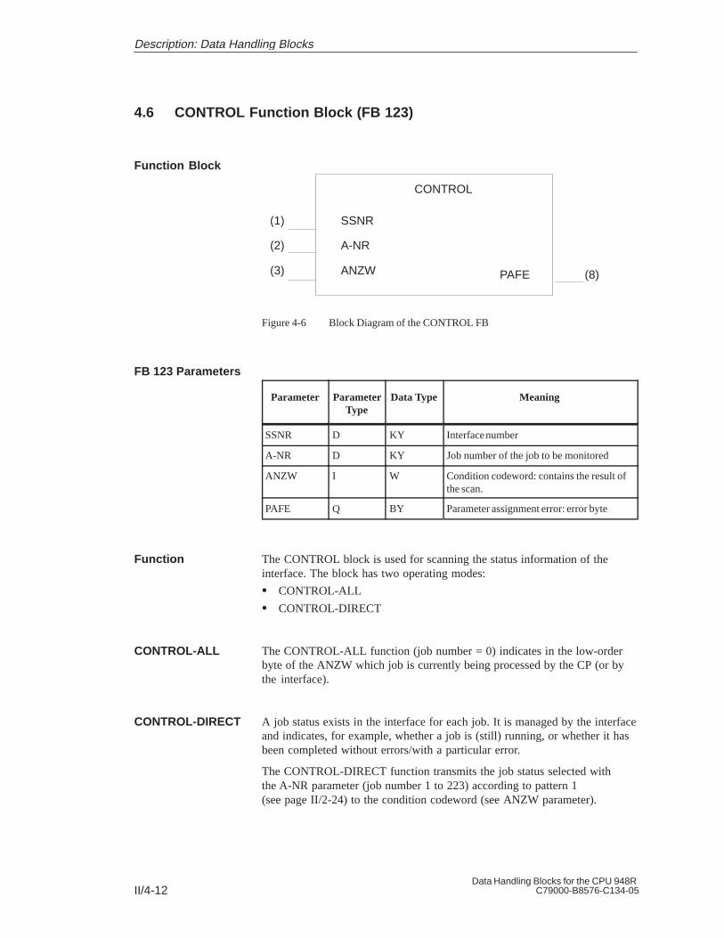
II/4-12Data Handling Blocks for the CPU 948R
C79000-B8576-C134-05
4.6 CONTROL Function Block (FB 123)
(1) SSNR
(2) A-NR
(3) ANZW
CONTROL
PAFE (8)
Figure 4-6 Block Diagram of the CONTROL FB
Parameter ParameterType
Data Type Meaning
SSNR D KY Interface number
A-NR D KY Job number of the job to be monitored
ANZW I W Condition codeword: contains the result ofthe scan.
PAFE Q BY Parameter assignment error: error byte
The CONTROL block is used for scanning the status information of theinterface. The block has two operating modes:
CONTROL-ALL
CONTROL-DIRECT
The CONTROL-ALL function (job number = 0) indicates in the low-orderbyte of the ANZW which job is currently being processed by the CP (or bythe interface).
A job status exists in the interface for each job. It is managed by the interfaceand indicates, for example, whether a job is (still) running, or whether it hasbeen completed without errors/with a particular error.
The CONTROL-DIRECT function transmits the job status selected withthe A-NR parameter (job number 1 to 223) according to pattern 1(see page II/2-24) to the condition codeword (see ANZW parameter).
Function Block
FB 123 Parameters
Function
CONTROL-ALL
CONTROL-DIRECT
Description: Data Handling Blocks

II/4-13Data Handling Blocks for the CPU 948RC79000-B8576-C134-05
4.7 RESET Function Block (FB 124)
(1) SSNR
(2) A-NR
PAFE (8)
Figure 4-7 Block Diagram of the RESET FB
Parameter ParameterType
Data Type Meaning
SSNR D KY Interface number
A-NR D KY Job number of the job to be reset
PAFE Q BY Parameter assignment error: error byte
The RESET block is RLO-dependent; the handshake with the interface isonly carried out if ”RLO = 1” has been transferred to the function block.
RESET-ALL
RESET-DIRECT
The RESET-ALL function (job number = 0) resets all jobs of this interface. Itdeletes all user data or interrupts all currently running jobs.
With the ”direct” reset function (job 0), only the specified job of theinterface is reset.
Function Block
FB 124 Parameters
Function
Description: Data Handling Blocks

II/4-14Data Handling Blocks for the CPU 948R
C79000-B8576-C134-05
4.8 SYNCHRON Function Block (FB 125)
(1) SSNR
(2) A-NR
PAFE (8)
Figure 4-8 Block Diagram of the SYNCHRON FB
Parameter ParameterType
Data Type Meaning
SSNR D KY Interface number
BLGR D KY Frame size
PAFE Q BY Error byte
The SYNCHRON block initializes the interface. The interface is deleted andpreset, and the frame size is declared between the interface and the CPU.Every interface must be initialized on a ”cold restart” (OB 20), in the”manual warm restart” (OB 21) and on a ”cold restart with memory”(OB 22). If the ”soft” STOP mode is also to be used, the SYNCHRON blockmust be called from the associated restart block (OB 38) for the requiredinterfaces.
In the programming examples below, FB 125 is called depending on theevaluation of the H flag word.
CP switched:
STL Explanation
:A F0.2:JC FB 125
NAME :SYNCHRON
Am master
SYNCHRON DHB (FB 125) call on restart (OB 20, 21, 22), CP one-sided,CP is in subunit A:
STL Explanation
:A F0.4:JC FB 125
NAME :SYNCHRON
Am subunit A
Function Block
FB 125 Parameters
Function
Examples ofSYNCHRON DHBCalls on Restart
Description: Data Handling Blocks

II/4-15Data Handling Blocks for the CPU 948RC79000-B8576-C134-05
SYNCHRON DHB (FB 125) call on restart (OB 20, 21, 22), CP one-sided,CP is in subunit B:
STL Explanation
:A F0.4:JC FB 125
NAME :SYNCHRON
Am subunit B
If the interface has been passivated by an error (NAU..., for instance), youmust depassivate and synchronize after correcting the error.
The identifier D0H is set in the PAFE byte for the duration ofsynchronization. FB 125 must therefore be called as long as this identifierexists.
STL Explanation
::O F 10.0:L KT 150.2:SE T 1:O(:L FY 8:L KH 0000:><F:):O F 10.0:R F 10.0:= F 11.0
Program for CP 1F 10.0 must be set whenCP 1 has been repairedDuration of depassivation max. 15 sec.
PAFE byte CP 1
F 10.0 must be set whenCP 1 has been repaired
:JC FB 125NAME :SYNCHRONSSNR : KY0.0BLGR : KY0.6PAFE : FY 8
:A F 11.0:A T 1:BEC::A F 11.0:R F 11.0:JC FBxx:L KB 0:T FY 8
Page no. for CP 1
Depassivation requested?15 sec. not yet elapsed?Yes –>BE because only 1 CP can be insertedat any one time15 sec. not yet elapsed?
Error message: CP 1 cannot be depassivated
(Continued on next page)
Calling theSYNCHRON DHB(FB 125) Cyclically
Description: Data Handling Blocks

II/4-16Data Handling Blocks for the CPU 948R
C79000-B8576-C134-05
STL Explanation
:::O F 10.1:L KT 150.2:SE T 1:O(:L FY 9:L KH 0000:><F:):O F 10.1:R F 10.1:= F 11.1:JC FB 125
NAME :SYNCHRONSSNR : KY0.2BLGR : KY0.6PAFE : FY 9
:A T 1:BEC::A F 11.1:R F 11.1:JC FBxx:L KB 0:T FY 9::
Program for CP 2F 10.1 must be set whenCP 2 has been repairedDuration of depassivation max. 15 sec.
PAFE byte CP 2
F 10.1 must be set whenCP 2 has been repaired
Page no. for CP 2
Only one CP can be inserted at any onetime
Error message: CP 2 cannot be depassivated
Program for CP 3
The FB is called once only via flag 10.0. The block call remains autonomousthanks to the ”D0” identifier.
Only one interface may be synchronized at any one time. The interfaces areprocessed in sequence.
IMPORTANT:
Please note that only one SYNCHRON DHB call can be executed per cyclesince, otherwise, errors would occur in the acknowledgement monitoringtime between the CPU and the CP.
Description: Data Handling Blocks
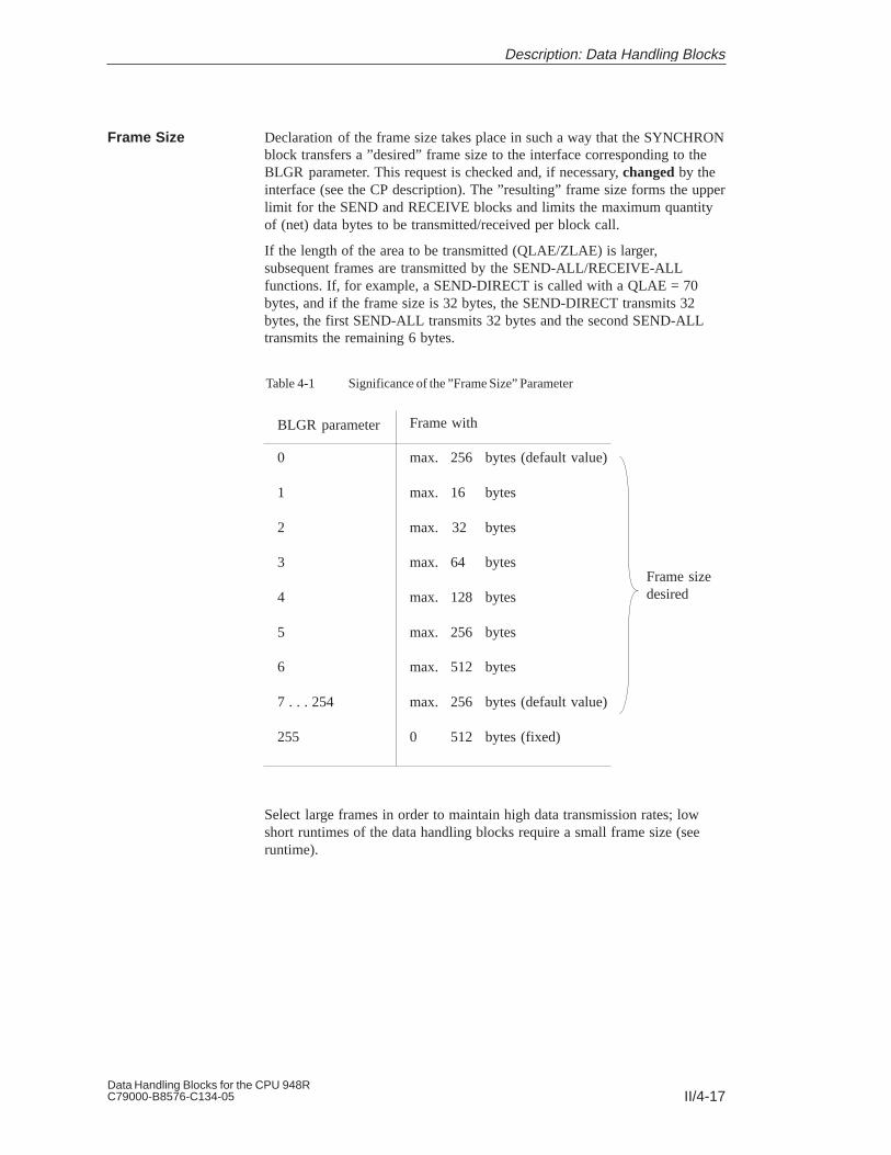
II/4-17Data Handling Blocks for the CPU 948RC79000-B8576-C134-05
Declaration of the frame size takes place in such a way that the SYNCHRONblock transfers a ”desired” frame size to the interface corresponding to theBLGR parameter. This request is checked and, if necessary, changed by theinterface (see the CP description). The ”resulting” frame size forms the upperlimit for the SEND and RECEIVE blocks and limits the maximum quantityof (net) data bytes to be transmitted/received per block call.
If the length of the area to be transmitted (QLAE/ZLAE) is larger,subsequent frames are transmitted by the SEND-ALL/RECEIVE-ALLfunctions. If, for example, a SEND-DIRECT is called with a QLAE = 70bytes, and if the frame size is 32 bytes, the SEND-DIRECT transmits 32bytes, the first SEND-ALL transmits 32 bytes and the second SEND-ALLtransmits the remaining 6 bytes.
Table 4-1 Significance of the ”Frame Size” Parameter
Frame sizedesired
BLGR parameter
0
1
2
3
4
5
6
7 . . . 254
255
Frame with
max. 256 bytes (default value)
max. 16 bytes
max. 32 bytes
max. 64 bytes
max. 128 bytes
max. 256 bytes
max. 512 bytes
max. 256 bytes (default value)
0 512 bytes (fixed)
Select large frames in order to maintain high data transmission rates; lowshort runtimes of the data handling blocks require a small frame size (seeruntime).
Frame Size
Description: Data Handling Blocks

II/4-18Data Handling Blocks for the CPU 948R
C79000-B8576-C134-05
Description: Data Handling Blocks
Preface, Contents
Working with COM 155 H 1
Main Menu 2
Configuring and Initializing 3
Configuring the I/O 4
Error Diagnostics andDocumentation 5
C79000-B8576-C135-05
COM 155 HProgrammer Software for Configuring the S5-155H ProgrammableController
User’s Guide(S5-155H, Part III)
SIMATIC S5

iiCOM 155H
C79000 B8576 C135 05
#$.()0'*)/$).)*/$ .2#$#4*0.#*0'*. -1 /* ).0- 4*0-*2)+ -.*)'.! /4.2 ''./*
+-*/ //# +-*0/)*)) / ,0$+( )/# . )*/$ .- #$"#'$"#/ $)/# ()0'42-)$)"
/-$)"' )- (-& .!*''*2.*-$)"/*/# ' 1 '*!)" -
!Danger
$)$/ ./#/ /#. 1 - + -.*)'$)%0-4*-.0./)/$'+-*+ -/4(" 2$''- .0'/$!+-*+ -+- 0/$*).- )*//& )
!Warning
$)$/ ./#/ /#. 1 - + -.*)'$)%0-4*-.0./)/$'+-*+ -/4(" )- .0'/$!+-*+ -+- 0/$*).- )*//& )
!Caution
$)$/ ./#/($)*-+ -.*)'$)%0-4*-+-*+ -/4(" )- .0'/$!+-*+ -+- 0/$*).- )*//& )
Note
-2.4*0-// )/$*)/*+-/$0'-'4$(+*-/)/$)!*-(/$*)*)/# +-*0/#)'$)"/# +-*0/*-/*+-/$0'-
+-/*!/# *0( )//$*)
# 1$ .4./ ((4*)'4 . /0+)*+ -/ $)*)%0)/$*)2$/#/#$.()0'
)'4 .#*0' ''*2 /*$)./'')2*-&*)/#$. ,0$+( )/0'$!$ + -.*).-
!$) .+ -.*).2#*- 0/#*-$5 /**(($..$*)/*"-*0))/*/"$-0$/. ,0$+( )/)
.4./ (.$)*-) 2$/# ./'$.# .! /4+-/$ .)./)-.
*/ /# !*''*2$)"
!Warning
#$. 1$ )$/.*(+*) )/.(4*)'4 0. !*-/# ++'$/$*). .-$ $)/# /'*"*-/# / #)$' .-$+/$*))*)'4$)*)) /$*)2$/# 1$ .*-*(+*) )/.!-*(*/# -()0!/0- -.2#$##1 )++-*1 *-- *(( ) 4$ ( ).
#$.+-*0/)*)'4!0)/$*)*-- /'4).! '4$!$/$./-).+*-/ ./*- . /0+)$)./'' *-- /'4)*+ -/ )($)/$) .- *(( )
)- - "$./ - /- (-&.*!
#$-+-/$ .0.$)"!*-/# $-*2)+0-+*. .)4*/# -)( .$)/#$.*0( )/2#$#- ! -/*/- (-&.($"#/$)!-$)" 0+*)/# -$"#/.*!/# /- (-&*2) -.
#1 # & /# *)/ )/.*!/#$.()0'!*-"- ( )/2$/#/# #-2- ).*!/2- .-$ $) 1$/$*).))*/ +- '0 )/$- '42 ))*/"0-)/ !0''"- ( )/*2 1 -/# /$)/#$.()0'- - 1$ 2 - "0'-'4))4) ..-4*-- /$*).$)'0 $).0. ,0 )/ $/$*).0"" ./$*).!*-$(+-*1 ( )/- 2 '*(
Siemens AG 1994 #)$'/.0% //*#)"
Disclaimer of LiabilityCopyright Siemens AG 1994 All rights reserved
# - +-*0/$*)/-).($..$*)*-0. *!/#$.*0( )/*-$/.*)/ )/.$.)*/+ -($// 2$/#*0/ 3+- ..2-$// )0/#*-$/4!! ) -.2$'' '$' !*-(" .''-$"#/.$)'0$)"-$"#/.- / 4+/ )/"-)/*-- "$./-/$*)*!0/$'$/4(* '*- .$")- - . -1
$ ( ). - $#0/*(/$.$ -0)".70))/-$ ./ #)$& .# !/." $ /)0./-$ 0/*(/$.$ -0)"..4./ ( *./!#670 -) -"
Siemens Aktiengesellschaft C79000-B8576-C135
Safety Guidelines
Qualified Personnel
Correct Usage
Trademarks

iiiCOM 155HC79000-B8576-C135-05
Preface (How to Use This Manual)
This User’s Guide describes the purpose and use of the functions of theCOM 155H (CPU 948R) Configuring Package. This package not onlyenables user-friendly configuring of the S5-155H PLC, but also offersdiagnostics and documentation functions. These are designed specificallywith the requirements of the S5-155H in mind.
COM 155H comprises a screen form system for user prompting in thefollowing situations:
When configuring the S5-155H
Fault diagnostics and error display in plaintext
Documentation of the redundancy-specific part of the configuration.
The COM functions are grouped into screen forms according to task and canbe activated in the relevant screen form on the programmer. The screenforms have a menu structure (see Chapter 1).

ivCOM 155H
C79000-B8576-C135-05
This User’s Guide is aimed at technicians, programming staff andmaintenance personnel with general systems knowledge. If you have anyquestions which are not answered by this Guide, please consult your localSiemens representative.
The information below concerning the contents of the individual chapters isdesigned to make it easier for you to use this User’s Guide.
This chapter gives you information on the component parts, the scope ofsupply and all possible operator inputs (menu tree) of the COM 155Hsoftware package.
Here, you are introduced to the main menu for your configuring work withall the relevant screen forms, including the input and output parameters.
In the main menu, you can define the data source (programmable controlleror programmer) for the configuration. In addition, you have access tofunctions such as start/stop programmable controller, diagnostics, systemhandling with output of directories of contents and initiation of load anddelete procedures.
This chapter describes assignment of parameters to the operating system, theDB and DX data blocks and the I/O areas of the individual expansion units(EUs). There is also an explanation of how to define the address areas ofone-sided and redundant I/O.
In this chapter, you will learn how to configure the I/O - digital input andoutput modules, analog input and output modules, CPs and IPs.
You will find out how to get from the main I/O basic screen to the individualI/O screen forms where you enter the configuring data for the digital andanalog inputs/outputs and the CPs and IPs.
This chapter gives you information on the possibilities and methods ofsearching for errors which can occur in the programmable controller aftertransfer of the configuration data. You can gain an overview of errors whichhave occurred and you can also obtain detailed information on eachindividual error.
The procedure for documenting your configuration is then described.
The alphabetical index at the end of the manual will help you locate the mostimportant terms in the manual.
The remarks form at the very end of the manual is provided for yourcomments and recommendations.
See the Preface to ”S5-155H Programmable Controller” (Part I) in thismanual.
Target Group
Notes on theContents
Chapter 1:Working withCOM 155H
Chapter 2:Main Menu
Chapter 3:Configuring andInitializing
Chapter 4:Configuring the I/O
Chapter 5: ErrorDiagnostics andDocumentation
Index
Remarks Form
ReferenceLiterature
Preface

vCOM 155HC79000-B8576-C135-05
Contents
1 Working with COM 155H III/1-1. . . . . . . . . . . . . . . . . . . . . . . . . . . . . . . . . . . . . . . . . . . . . . . .
1.1 Installing and Operating COM 155H III/1-2. . . . . . . . . . . . . . . . . . . . . . . . . . . . . . . Configuration III/1-2. . . . . . . . . . . . . . . . . . . . . . . . . . . . . . . . . . . . . . . . . . . . . . . . . . . Installation III/1-2. . . . . . . . . . . . . . . . . . . . . . . . . . . . . . . . . . . . . . . . . . . . . . . . . . . . . Operator Prompting III/1-2. . . . . . . . . . . . . . . . . . . . . . . . . . . . . . . . . . . . . . . . . . . . . Exiting a Screen Form (V 3.x) III/1-3. . . . . . . . . . . . . . . . . . . . . . . . . . . . . . . . . . . . . Alternatives in COM 155H III/1-3. . . . . . . . . . . . . . . . . . . . . . . . . . . . . . . . . . . . . . . .
1.2 Installing and Starting COM 155H under ”STEP 5 to Version 3.x” III/1-4. . . . . .
1.3 COM 155H Functions under ”STEP 5 to Version 3.x” III/1-5. . . . . . . . . . . . . . . . .
1.4 Installing and Starting COM 155H under ”STEP 5 Version 6.x” III/1-8. . . . . . . . Starting COM 155H III/1-8. . . . . . . . . . . . . . . . . . . . . . . . . . . . . . . . . . . . . . . . . . . . . .
1.5 COM 155H Functions under ”STEP 5 Version 6.x” III/1-9. . . . . . . . . . . . . . . . . . . Function Tree: COM 155H III/1-9. . . . . . . . . . . . . . . . . . . . . . . . . . . . . . . . . . . . . . . . The Object Menu III/1-9. . . . . . . . . . . . . . . . . . . . . . . . . . . . . . . . . . . . . . . . . . . . . . . . The Configuration Menu III/1-11. . . . . . . . . . . . . . . . . . . . . . . . . . . . . . . . . . . . . . . . . The Diagnostics Menu III/1-12. . . . . . . . . . . . . . . . . . . . . . . . . . . . . . . . . . . . . . . . . . The Documentation Menu III/1-13. . . . . . . . . . . . . . . . . . . . . . . . . . . . . . . . . . . . . . .
1.6 Installing and Starting COM 155H under ”STEP 5 Version 7.x” III/1-14. . . . . . . Starting COM 155H III/1-14. . . . . . . . . . . . . . . . . . . . . . . . . . . . . . . . . . . . . . . . . . . . .
1.7 COM 155H Functions under ”STEP 5 Version 7.x” III/1-15. . . . . . . . . . . . . . . . . . Function Tree: COM 155H III/1-15. . . . . . . . . . . . . . . . . . . . . . . . . . . . . . . . . . . . . . . The File Menu III/1-16. . . . . . . . . . . . . . . . . . . . . . . . . . . . . . . . . . . . . . . . . . . . . . . . . The Configuration Menu III/1-17. . . . . . . . . . . . . . . . . . . . . . . . . . . . . . . . . . . . . . . . . The PLC Menu III/1-18. . . . . . . . . . . . . . . . . . . . . . . . . . . . . . . . . . . . . . . . . . . . . . . . . The Documentation Menu III/1-19. . . . . . . . . . . . . . . . . . . . . . . . . . . . . . . . . . . . . . .
1.8 Explanation of Terms Used III/1-21. . . . . . . . . . . . . . . . . . . . . . . . . . . . . . . . . . . . . .
2 Main Menu III/2-1. . . . . . . . . . . . . . . . . . . . . . . . . . . . . . . . . . . . . . . . . . . . . . . . . . . . . . . . . . . . .
2.1 The Main Menu III/2-2. . . . . . . . . . . . . . . . . . . . . . . . . . . . . . . . . . . . . . . . . . . . . . . . . F1: <CONF PLC> III/2-2. . . . . . . . . . . . . . . . . . . . . . . . . . . . . . . . . . . . . . . . . . . . . . . F2: <CONF FD> III/2-3. . . . . . . . . . . . . . . . . . . . . . . . . . . . . . . . . . . . . . . . . . . . . . . . F3: <CONF PG> III/2-3. . . . . . . . . . . . . . . . . . . . . . . . . . . . . . . . . . . . . . . . . . . . . . . . PLC Functions, F4 III/2-4. . . . . . . . . . . . . . . . . . . . . . . . . . . . . . . . . . . . . . . . . . . . . . Diagnostics, F5 III/2-6. . . . . . . . . . . . . . . . . . . . . . . . . . . . . . . . . . . . . . . . . . . . . . . . . Defaults, F6 III/2-9. . . . . . . . . . . . . . . . . . . . . . . . . . . . . . . . . . . . . . . . . . . . . . . . . . . . System Handling, F7 III/2-9. . . . . . . . . . . . . . . . . . . . . . . . . . . . . . . . . . . . . . . . . . . .

viCOM 155H
C79000-B8576-C135-05
3 Configuring and Initializing III/3-1. . . . . . . . . . . . . . . . . . . . . . . . . . . . . . . . . . . . . . . . . . . . .
3.1 Configuring the S5-155H PLC (S5-DOS/Stage 6) III/3-2. . . . . . . . . . . . . . . . . . . . Configuration Functions Screen Form III/3-2. . . . . . . . . . . . . . . . . . . . . . . . . . . . . . Initializing the Operating System: <OS> III/3-3. . . . . . . . . . . . . . . . . . . . . . . . . . . . Configuring the I/Os: <IOCONF> III/3-4. . . . . . . . . . . . . . . . . . . . . . . . . . . . . . . . . .
3.2 Initializing the Operating SystemF1: <SYSTEM> (in the Initialize Operating System Basic Screen Form) III/3-5Operating System Parameters III/3-5. . . . . . . . . . . . . . . . . . . . . . . . . . . . . . . . . . . . RAM/PIQ Comparison Error III/3-5. . . . . . . . . . . . . . . . . . . . . . . . . . . . . . . . . . . . . . Operating System: Explanation of Parameters III/3-6. . . . . . . . . . . . . . . . . . . . . .
3.3 Initializing Activation of the StandbyF2: <TRAFDAT> (in the Initialize Operating System Basic Screen Form) III/3-9Transfer Data for Activating Standby III/3-9. . . . . . . . . . . . . . . . . . . . . . . . . . . . . . .
3.4 Initializing the I/O AreasF3: <I/O 314> (in the Initialize Operating System Basic Screen Form) III/3-11. Area Parameters of the Switched I/O in the EU III/3-11. . . . . . . . . . . . . . . . . . . . .
4 Configuring the I/O III/4-1. . . . . . . . . . . . . . . . . . . . . . . . . . . . . . . . . . . . . . . . . . . . . . . . . . . . .
4.1 General Structure of the I/O Configuration Screen Forms III/4-2. . . . . . . . . . . . . I/O Basic Screen Form III/4-2. . . . . . . . . . . . . . . . . . . . . . . . . . . . . . . . . . . . . . . . . . . Displays in the Configuration Screen Form III/4-3. . . . . . . . . . . . . . . . . . . . . . . . . . Processing the I/O Configuration Screen Form III/4-4. . . . . . . . . . . . . . . . . . . . . .
4.2 Structure of the Individual I/O Configuration Screen Forms III/4-6. . . . . . . . . . . . Digital Inputs: F1 III/4-6. . . . . . . . . . . . . . . . . . . . . . . . . . . . . . . . . . . . . . . . . . . . . . . . Legend: DI III/4-8. . . . . . . . . . . . . . . . . . . . . . . . . . . . . . . . . . . . . . . . . . . . . . . . . . . . . Digital Outputs: F2 III/4-9. . . . . . . . . . . . . . . . . . . . . . . . . . . . . . . . . . . . . . . . . . . . . . Legend: DQ III/4-11. . . . . . . . . . . . . . . . . . . . . . . . . . . . . . . . . . . . . . . . . . . . . . . . . . . Analog Inputs: F3 III/4-11. . . . . . . . . . . . . . . . . . . . . . . . . . . . . . . . . . . . . . . . . . . . . . Legend: AI (Types 15 and 16) III/4-13. . . . . . . . . . . . . . . . . . . . . . . . . . . . . . . . . . . . Analog Outputs: F4 III/4-15. . . . . . . . . . . . . . . . . . . . . . . . . . . . . . . . . . . . . . . . . . . . . CP/IP: F5 III/4-19. . . . . . . . . . . . . . . . . . . . . . . . . . . . . . . . . . . . . . . . . . . . . . . . . . . . .
5 Error Diagnostics and Documentation III/5-1. . . . . . . . . . . . . . . . . . . . . . . . . . . . . . . . . . .
5.1 Static Error Image of the I/Os III/5-2. . . . . . . . . . . . . . . . . . . . . . . . . . . . . . . . . . . . .
5.2 Error Data Block III/5-5. . . . . . . . . . . . . . . . . . . . . . . . . . . . . . . . . . . . . . . . . . . . . . . . Calling the Error DB III/5-5. . . . . . . . . . . . . . . . . . . . . . . . . . . . . . . . . . . . . . . . . . . . . Example of an Error Record Printout (Programmable Controller) III/5-6. . . . . . . Structure of the Error Diagnostics Screen Form III/5-6. . . . . . . . . . . . . . . . . . . . . Legend: Error DB III/5-7. . . . . . . . . . . . . . . . . . . . . . . . . . . . . . . . . . . . . . . . . . . . . . .
5.3 Documenting with COM 155H III/5-8. . . . . . . . . . . . . . . . . . . . . . . . . . . . . . . . . . . . . Printing the Configuration Overview III/5-8. . . . . . . . . . . . . . . . . . . . . . . . . . . . . . . . Printing the Configuration DB/DX III/5-9. . . . . . . . . . . . . . . . . . . . . . . . . . . . . . . . . . Functions in the Print Menu III/5-9. . . . . . . . . . . . . . . . . . . . . . . . . . . . . . . . . . . . . . .
Contents - Part III

III/1-1COM 155HC79000-B8576-C135-05
Working with COM 155 H
This chapter describes how to start the COM 155H software package, thedifferent versions of the main menu depending on whether you are using”STEP 5 Version 3.x”, ”STEP 5 Version 6.x” or ”STEP 5 Version 7.x”, andimportant terms used in the configuring and operator software.
1

III/1-2COM 155H
C79000-B8576-C135-05
1.1 Installing and Operating COM 155H
The scope of supply of COM 155H consists of
One 3 1/2” diskette in MS-DOS format (for STEP 5 Version 3.x andSTEP 5 Version 6.x) and
One 3 1/2” diskette in MS-DOS format (for STEP 5 Version 7.x)
You will find information on the contents of the diskettes in the relevantreadme.txt file.
The COM 155H software package runs on the following: AT-compatible PCs
with MS-DOS 5.0 or Windows 95 and the STEP 5 Basic Package,Version 3.x, 6.x or 7.x).
The installation depends on the STEP 5 version used (see Sections 1.2 and1.4).
All COM 155H functions are activated via menu-driven operator promptingfrom the programmer.
Under STEP 5 Version 3.x, COM 155H can be operated using thefunction keys and the keyboard, like all other programmer packages.
Under STEP 5 Version 6.x or STEP 5 Version 7.x, the COM 155H screenscan be selected using drop-down menus instead of the function keys.
However, only the screen forms are selected using the drop-down menus;within the screen forms themselves, the function keys are used.
Selection of a softkey on the screen with the mouse has the same effect aspressing the corresponding function key on the keyboard.
If COM 155H has been installed under STEP 5 Version 3.x, you can callCOM 155H from the S5 command interpreter to access the following:
The ”Language Selection” screen form, if COM 155H has been installedin several languages. If not, skip this screen form.
The ”Defaults” screen form (see Figure 1-1).
After setting the defaults (F3 <SELECT>), press F6 <EXEC> to reach the”Main Menu” from where you can branch to the individual submenususing the softkeys <F2> to <F7>.
If COM 155H has been installed under STEP 5 Version 6.x or STEP 5Version 7.x, you reach the Main Menu by starting STEP 5 (see Figure 1-4).
You can use the ”Change” function to change to ”COM 155H” which willbring you to the COM 155H Main Menu.
Scope of Supplyand File Names
Configuration
Installation
OperatorPrompting
Working with COM 155H

III/1-3COM 155HC79000-B8576-C135-05
If you exit a screen form with <F8>, COM 155H responds in the followingway:
If there is no screen form in the higher-level hierarchy (that is, you havereturned to a branch menu), the screen form contents remain on the screenbut can no longer be changed.
The branch menu is then displayed and processed. Press the key again toclear the screen.
If the higher-level hierarchy also contains a screen form to be processed,this new higher-level screen form is displayed and processed.
In the configuring screen forms of COM 155H, there are fields containingalternatives for your selection. You can make your selection usingF3 <SELECT>. Press F3 and then press it repeatedly to display eachavailable alternative in turn. The alternatives field is not exited.
The COM 155H V3.0 can be used with all CPU 946R/947R and 948Rs. Toconvert the DX1 of a CPU 946R/947R to a DX1 of a CPU 948R:
Select presets for 948R (PG may not be online to a CPU 946R)
Load DX1 of the 946R/947R from FD.
Reply to the query whether the DX1 of the 946R/947R should be set withNO. The DX1 is then converted to 948R format and is located in the PGmemory.
Save DX1 to FD.
Exiting a ScreenForm (V 3.x)
Alternatives inCOM 155H
Working with COM 155H

III/1-4COM 155H
C79000-B8576-C135-05
1.2 Installing and Starting COM 155H under ”STEP 5 to Version 3.x”
Insert the diskette for STEP 5 Version 3.x and STEP 5 Version 6.x in drive A:.
Copy the files to the STEP5 system directory on the hard disk C: (for example, COPY A: *.* C:\STEP5\S5_SYS).
Make sure all files are available on the hard disk. The COM 155H packagecan only be called up from the S5 command interpreter (KOMI). TheDefaults screen form is displayed:
CPU FIRMWARE : 12
SYMBOLS : NO
FOOTER : NO
PRINT WIDTH : NORMAL
OP MODE : OFFPATH NAME :
SELECT EXEC BACK
DEFAULTS COM 155H / PEC16
F6F5F4F3F2F1 F7 F8
Figure 1-1 COM 155H Defaults Screen Form
Press <SHIFT> + <Cursor to the right> or <Cursor to the left> to changefrom one half of the screen to the other. Press <Cursor up> and <Cursordown> to move the cursor up and down, respectively.
If you position the cursor after the colon of the individual terms and thenpress F3 <SELECT>, you can enter or change the individual data easily.
When you have entered all necessary data, press F6 <EXEC>. This entersthe defaults and makes them immediately valid. The COM 155H MainMenu bar appears.
If you want to exit the COM 155H package, press the <ESC> key.
Installing on theProgrammer withMS-DOS andSTEP 5 to V3.x
Starting COM 155H
Working with COM 155H

III/1-5COM 155HC79000-B8576-C135-05
1.3 COM 155H Functions under ”STEP 5 to Version 3.x”
The starting point for the COM 155H function tree is the ”Main Menu” (seeFigure 2-1), which you reach after entering the defaults.
The individual operator screen forms are arranged in the form of the treeshown in Figures 1-2 and 1-3. In each case, the relevant menu bar is shownwith the key numbers and the functions which can be called.
The softkeys shown horizontally at the top of the figures below describethe COM 155H Main Menu.
There are follow-on screen forms for each of the functions selectable inthe main menu. The functions offered by the follow-on screen forms canbe seen from the menu bars shown.
The call paths and dependencies are symbolized by connecting lines.
If the configuration branch (F1/F2/F3 in the Main Menu) is exited, youmust store the configured data on the destination medium (diskette orprogrammable controller) by confirming the acknowledgement messagebefore returning to the Main Menu.
Function key F4 <PLC FCT> in the Main Menu contains mechanisms forstarting and stopping the S5-155H programmable controller. Special errorindicators and diagnostics functions can be activated using the<DIAGN.> key (F5).
The Main Menu function <SYSHAN> (system handling = F7) enables thedisplay of the configured external I/O available in system DB1. Followingthis, selective or complete documentation of the configured data from theprogrammable controller or from the program file can be generated. Inaddition, you can initiate deletions in the programmable controller or ondiskette (see Figure 1-3).
Function Tree:COM 155H
Working with COM 155H

III/1-6COM 155H
C79000-B8576-C135-05
#
$')&),%+&&)*+(O
pera
ting
syst
em b
asic
scr
een
form
#
#
#"
"
OS
scr
een
form
Tran
sfer
dat
a sc
reen
form
I/O s
cree
n fo
rm
#
!
I/O c
onfig
urat
ion
scre
en fo
rm
#
#
PLC
func
tions
#-!
Dia
gnos
tics
basi
c sc
reen
form
#
Err
or d
iagn
ostic
s sc
reen
form
-
I/O e
rror
imag
e ba
sic
scre
en fo
rm
#
#
Con
trol
scr
een
form
Err
or d
iagn
ostic
s sc
reen
form
Err
or d
iagn
ostic
s sc
reen
form
Sta
tus
scre
en fo
rm w
ith s
ubun
it B
Figure 1-3
"
Fla
g w
ord
scre
en fo
rm
I/O c
onfig
urat
ion
scre
en fo
rmI/O
bas
ic s
cree
n fo
rm
Con
figur
atio
n fu
nctio
ns
Figure 1-2 COM 155H Screen Form Tree for the S5-155H Programmable Controller (1)
Working with COM 155H

III/1-7COM 155HC79000-B8576-C135-05
!$&#&)"(##&'(%
Dire
ctor
y m
enu
Aux
iliar
y fu
nctio
ns s
cree
n fo
rm
Prin
t men
u
Sys
tem
han
dlin
g m
enu
Del
ete
men
u (D
X 1
)
Figure 1-3 COM 155H Screen Form Tree for the S5-155H Programmable Controller (2)
Working with COM 155H

III/1-8COM 155H
C79000-B8576-C135-05
1.4 Installing and Starting COM 155H under ”STEP 5 Version 6.x”
1. Insert the diskette for STEP 5 Version 3.x and STEP 5 Version 6.x in drive A:.
2. Copy the files into the STEP 5 system directory on the hard disk (for example, COPY A: *.* C:\STEP5\S5_ST).
3. Change the logon file S5KES01X.OPT as described below:
a) If there is not yet any software package loaded under STEP 5 V6.x, change the name of the S5PEC16X.OPT file supplied to S5KES01X.OPT, and copy this file also into the system directory.
b) If there are software packages (GRAPH5, for example) alreadyloaded, you must modify the S5KES01X.OPT file in your system directory:
Load the S5KES01X.OPT file into the Editor and extend the userinformation by incrementing the ”Number of subsequent elemententries” by 1 and by entering the code for the COM 155H softwarepackage.
)/)9%177);76 %5))1'/26)(&)7:))1-19)57)('200%69)5<7,-1+
)/6)-6%'200)171)/)0)17'216-6762*7,5)) 6:,-',0867&):-7,-1
21)/-1)0%;',%5%'7)56)%1-1+2*7,))/)0)17-7)06
=&<7)6" # $2*7,)352+5%01%0)2*7,));)'87%&/)352+5%0
=352+5%0180&)5%1%/2+286727,)3%5%0)7)5%66-+10)17
-16.)6;0)1
=25&<7)62*7);772%33)%5-17,),%1+)0)18
-/)6758'785) 80&)52*)/)0)176
= &)/21+-1+72)/)0)17
=
7%572*86)5-1*250%7-21
80&)52*68&6)48)17)/)0)17)175-)6*25)9)/ %33/-'%7-216
52+5%01%0) 52+5%0180&)5 );7-10)18
!
Starting COM 155H from the STEP 5 menu bar:
Beginning with the ”Change” menu command, select the COM 155Hsoftware package entered there.
The drop-down menus then contain a range of COM-specificsupplementary functions, as well as the standard functions of STEP 5.
Installing onProgrammer withMS-DOS andSTEP 5 V6.x
Starting COM 155H
Working with COM 155H

III/1-9COM 155HC79000-B8576-C135-05
1.5 COM 155H Functions under ”STEP 5 Version 6.x”
Figure 1-4 shows what the STEP 5 menu bar with the Main Menu and theindividual drop-down menus look like after changing to COM 155H.
The object-oriented or project-oriented defaults entered underSTEP 5 V6.x are accepted by COM 155H.
If you select an S5 standard function, the COM 155H user interface issuppressed and the relevant function is started. After completing thefunction, the COM 155H Main Menu bar appears again.
%($
,%($
+*'(*&
++" '&',%"+,
0000
('" -*,"('
#, ",(* " '(+,"+ ' &', (-&',,"(' !' %)
('"
%($+
0000
,/)
('" -*,"('
'
,,-+%($
,,-+.*"%+
(*
(*.*"%+
(*(-,)-,+
"+)%/"'(
0000
(**-'',
,,**(*"& "'
+/+,% +,,-+/,
+/+,% (',*(%/,
**(**(&)*( *"%
**(**(&
'*,
+
%,*".
-+),!+
-*,!*
"+,($/++" '&',+
.*+"('"'(
)$ .*+"('+
"',!)*( *&"%
"',!
*(&,!)*( *&"%
*(&,!
,,"' +
Figure 1-4 COM 155H Main Menu under STEP 5 Version 6.x
Figure 1-5 shows the functions available in the Object menu for displayingdirectories or handling data blocks and files, and how you can activate these.
Function Tree:COM 155H
The Object Menu
Working with COM 155H

III/1-10COM 155H
C79000-B8576-C135-05
#, ",(* " '(+,"+ ' &', (-&',,"(' !' %)
('"
%($+
////
,.)
('" -*,"('
'
"*,(*.
*'+*
(&)*
%,
"*,(*."')*( *&"%
"*,(*."'
%,"')*( *&"%
%,"'
"',!)*( *&"%
"',!
"%/"%
"%/
/"%
",!"'
"%/"%
"%/
/"%
"',!)*( *&"%
"',!
%,"('
%%
'-+(*)*(#,-%,+,
*'(*&(*+%,"('
Figure 1-5 The COM 155H Object menu
You can choose between the following CPU types in the Selection screenform:
CPU 946R up to firmware version 11
CPU 948R from firmware version 12
CPU 948R
Selection of this menu entry calls the COM 155H directory functions.
”Directory in program file” or ”Directory in PLC” gives you an overview ofthe configuration of DX1.
”Delete in program file” or ”Delete in PLC” takes you via a Selection menuto the ”Delete I/O” screen form, where you can select certain parts of theDX1 configuration for deletion.
The ”All” function deletes the complete DX1.
CPU Type
Configuration DX1
Working with COM 155H

III/1-11COM 155HC79000-B8576-C135-05
Figure 1-6 shows the COM 155H functions available in the Configurationmenu for initializing the operating system and for configuring the I/O, andhow you activate these functions.
#, ",(* " '(+,"+ ' &', (-&',,"(' !' %)
%($
,%($
+*'(*&
++" '&',%"+,
0000
('" -*,"('
/+,&
*+
"',!)*( *&"%
"',!
)*,"' +/+,&
('" -*,"('
%,
. ,(
. ,(
'('" -*,"('
'
" ",%"')-,+
" ",%(-,)-,+
'%( "')-,+
'%( (-,)-,+
"',*
%,"('
%%
/%
/%
',**-),
',**-),
('" -*,"(' %)
Figure 1-6 The COM 155H Configuration Menu
You reach the submenu for initializing the operating system via the ”Programfile/PLC” Selection menu.
Select ”System” to open the operating system basic screen form (seeFigures 3-2 and 3-5).
”TRAFDAT” takes you to the next submenu (see Figure 3-6) for selectingthe screen forms for activating the standby (see Section 3.3).
After selecting ”I/O 314”, COM 155H opens the screen form for enteringthe I/O areas for the switched I/O (see Figure 3-7).
The ConfigurationMenu
Initializing theOperating System
Working with COM 155H

III/1-12COM 155H
C79000-B8576-C135-05
You reach the submenu for configuring the I/O via the ”Program file/PLC”Selection menu.
After selecting the relevant menu command, the associated I/O screenform is opened (see Figure 4-1).
Pressing F3 <SELECT> in the softkey bar of the I/O screen form sets therelevant I/O type.
Figure 1-7 shows which COM 155H functions you can activate fordiagnostics purposes on the S5-155H in addition to the STEP 5 test functions.
) )%' $%()( $#$) %*#$))%$ $ "&
))*("%!
))*(+'"(
%'
%'+'"(
%'%*)&*)(
(&",$%
......
%''*$$)
))''%'#$
(,()#"())*(,)
(,()#"%$)'%",)
''%''%#&'%'#"
''%''%#
)')
)%&
%#&'((##%',
(&",##%',%$)$)(
#%',(-
,()#&'#)'(
Figure 1-7 The COM 155H Diagnostics Menu
After selecting one of the COM 155 functions in the Diagnostics menu, youreach the relevant processing screen form:
Force redundant PLC
Takes you to the ”PLC Functions” screen form (see Figure 2-2).
Static error image in PLC
Takes you to the ”Static Error Image of the I/Os” screen form(see Figure 5-1).
H system flag status byte
Takes you to the ”COM 155H Status Screen Form” (see Figure 2-6).
H system flag control byte
Takes you to the ”COM 155H Control Screen Form” (see Figure 2-7).
H error from program file
Takes you to the ”Error Diagnostics” screen form (see Figure 5-5). Theerror DB configured in DX1 is loaded from the diskette or the hard diskand displayed on the screen.
H error from PLC
Takes you to the ”Error Diagnostics” screen form (see Figure 5-4). Theerror DB configured in DX1 is loaded from the PLC and displayed.
Configuring the I/O
The DiagnosticsMenu
ActivatingDiagnosticsFunctions
Working with COM 155H

III/1-13COM 155HC79000-B8576-C135-05
Figure 1-8 shows the print functions you can activate in COM 155H.
# #! "#" # $##
# $#"
#$# $#"
$#"
$# $#"
#!
##& "
#!$!#
!!!"""
!
!# !!
!#
##"
!#%#"##
!#! !#!"
#!#!
Figure 1-8 The COM 155H Documentation Menu
You reach the submenu for print selection via the menu entries ”From theprogram file” or ”From the PLC”, depending on the source desired.
Depending on the menu command selected, all types of the selected I/Ocategory are output to the printer in each case.
After activating Selection (types), you reach the ”Print Menu” screenform in which you can select individual types for printing.
If you activate the H error messages function, the reported errors locatedin the error DB of the selected file are printed out in compressed form.
After selecting Config. dir. , an overview of the DX1 configuration isoutput.
TheDocumentationMenu
Activating PrintFunctions
Working with COM 155H

III/1-14COM 155H
C79000-B8576-C135-05
1.6 Installing and Starting COM 155H under ”STEP 5 Version 7.x”
1. Insert the diskette for STEP 5 Version 7.x in drive A:.
2. Start the program install.exe and follow the instructions given by the installation program.
Starting COM 155H from the STEP 5 menu bar:
Beginning with the ”Change” menu command, select the COM 155Hsoftware package entered there.
The drop-down menus then contain a range of COM-specificsupplementary functions, as well as the standard functions of STEP 5.
Installing onProgrammer withMS-DOS andSTEP 5 V7.x
Starting COM 155H
Working with COM 155H

III/1-15COM 155HC79000-B8576-C135-05
1.7 COM 155H Functions under ”STEP 5 Version 7.x”
Figure 1-9 shows what the STEP 5 menu bar with the Main Menu and theindividual drop-down menus look like after changing to COM 155H.
The object-oriented or project-oriented defaults entered underSTEP 5 V 7.x are accepted by COM 155H.
If you select an S5 standard function, the COM 155H user interface issuppressed and the relevant function is started. After completing thefunction, the COM 155H Main Menu bar appears again.
), (0), ( .""+
.,'" 0
), (/
), (001/
001/.&)"
,. ".&)"/
,. "10-10/
.,$.*"/0
.,$.*"/0
5-"
0 %
0%"./
"5//&$+*"+0&/0
,10"./&,+
"./&,+,# ($"/
&+0%".,$.* &)"
&*0%"
/".+0".# "
File Editor Test PLC Management Documentation Change Help
,+#&$1.0&,+
,**+!/
4&0
,+#&$1.0&,+
//&$+*"+0&/0
1/0%/
.&+0"..*"0"./ ,,0".!&0,..&+0&!0%
1+ 0&,+/+#,
,. ""!1+!+05/0 )$001/50"5/0 )$,+0.,)50"
..,.#.,*.,$ &)"..,.#.,*
00..,.*$"&+
(" +!)&+$
10,*0& "3&.&+$+1)"3&.&+$
//&$+*"+0&/0/,+2".0
+$1$",),./
), (/0), (/
+%+ "!10-10, ,**+!/
.,*0%".,$.* &)" .,*0%"
.""+///&$+*"+0&/0.,$.*0.1 01."
.,//"#"."+ "/ &/0 %.""6&+6+"
Figure 1-9 COM 155H Main Menu under STEP 5 Version 7.x
Function Tree:COM 155H
Working with COM 155H

III/1-16COM 155H
C79000-B8576-C135-05
Figure 1-10 shows the functions available in the File menu for displayingdirectories or handling data blocks and files, and how you can activate these.
"(&#%$%#'( '&%&#")
#" "
File Editor Test PLC Management Documentation Change Help
%#'
#&
#"(%'#"
#!!"&
)'%'#%*"%#%!
%'#%*"
'"%#%!
'"
'#"
Figure 1-10 The COM 155H File menu
Selection of this menu entry calls the COM 155H directory functions.
”Directory in program file” or ”Directory in PLC” gives you an overview ofthe configuration of DX1.
”Delete in program file” or ”Delete in PLC” takes you via a Selection menuto the ”Delete I/O” screen form, where you can select certain parts of theDX1 configuration for deletion.
The ”All” function deletes the complete DX1.
The File Menu
Configuration DX1
Working with COM 155H

III/1-17COM 155HC79000-B8576-C135-05
Figure 1-11 shows the COM 155H functions available in the Configurationmenu for initializing the operating system and for configuring the I/O, andhow you activate these functions.
-)*$
()
'(*!%-)*$
&%!+(*!&%
!!*#%'+*)
!!*#+*'+*)
%#&%'+*)
%#&+*'+*)
%*(
#*!&%
##
-#
-#
%*((+'*
%*((+'*
Configuration Help
File Editor Test PLC Management Documentation Change Help
#&"*#&"(%
!%* (&($!#
!$* &%!+(*!&%
))!%$%*!)*
+)* )
(!%*(($*()&&*( !*&((!%*!*
#*
,.*&
,.*&
%&%!+(*!&%
Figure 1-11 The COM 155H Configuration Menu
You reach the submenu for initializing the operating system via the ”Programfile/PLC” Selection menu.
Select ”System” to open the operating system basic screen form (seeFigures 3-2 and 3-4).
”TRAFDAT” takes you to the next submenu (see Figure 3-5) for selectingthe screen forms for activating the standby (see Section 3.3).
After selecting ”I/O 314”, COM 155H opens the screen form for enteringthe I/O areas for the switched I/O (see Figure 3-6).
The ConfigurationMenu
Initializing theOperating System
Working with COM 155H

III/1-18COM 155H
C79000-B8576-C135-05
You reach the submenu for configuring the I/O via the ”Program file/PLC”Selection menu.
After selecting the relevant menu command, the associated I/O screenform is opened (see Figure 4-1).
Pressing F3 <SELECT> in the softkey bar of the I/O screen form sets therelevant I/O type.
Figure 1-12 shows which COM 155H functions you can activate fordiagnostics purposes on the S5-155H in addition to the STEP 5 test functions.
File Editor Test PLC Management Documentation Change Help
$"$
$ !
!"## "&
%$!%$ "&
"&
&#"$"#
&!
%$ #
"%$&#$'$$%#&$
&#$ $" &$
"" "" " "" ""
$$"" "
Figure 1-12 The COM 155H PLC Menu
You can choose between the following CPU types in the Selection screenform:
CPU 946R up to firmware version 11
CPU 946R from firmware version 12
CPU 948R
CPU 948RL
Configuring the I/O
The PLC Menu
CPU Type
Working with COM 155H

III/1-19COM 155HC79000-B8576-C135-05
After selecting one of the COM 155 functions in the PLC menu, you reachthe relevant processing screen form:
Force redundant PLC
Takes you to the ”PLC Functions” screen form (see Figure 2-2).
Static error image in PLC
Takes you to the ”Static Error Image of the I/Os” screen form(see Figure 5-1).
H system flag status byte
Takes you to the ”COM 155H Status Screen Form” (see Figure 2-6).
H system flag control byte
Takes you to the ”COM 155H Control Screen Form” (see Figure 2-7).
H error from program file
Takes you to the ”Error Diagnostics” screen form (see Figure 5-5). Theerror DB configured in DX1 is loaded from the diskette or the hard diskand displayed on the screen.
H error from PLC
Takes you to the ”Error Diagnostics” screen form (see Figure 5-4). Theerror DB configured in DX1 is loaded from the PLC and displayed.
Figure 1-13 shows the print functions you can activate in COM 155H.
)"$&*)(
)"*)&*)(
$"%$&*)(
$"%*)&*)(
$)'
") %$+&(
$) '%$ *') %$
''%'(((
%$ '
File Editor Test PLC Management Documentation Change Help
"%!()"%!(
$$*)&*)%%##$(
'%#)'%'# "'%#)
'$((( $#$) ()'%'#)'*)*'
'%(('$( () ', $,$
)"$&*)(
)"*)&*)(
$"%$&*)(
$"%*)&*)(
$)'
") %$+&(
$) '%$ *') %$
''%'(((
%$ '
Figure 1-13 The COM 155H Documentation Menu
ActivatingDiagnosticsFunctions
TheDocumentationMenu
Working with COM 155H

III/1-20COM 155H
C79000-B8576-C135-05
You reach the submenu for print selection via the menu entries ”From theprogram file” or ”From the PLC”, depending on the source desired.
Depending on the menu command selected, all types of the selected I/Ocategory are output to the printer in each case.
After activating Selection (types), you reach the ”Print Menu” screenform in which you can select individual types for printing.
If you activate the H error messages function, the reported errors locatedin the error DB of the selected file are printed out in compressed form.
After selecting Config. dir. , an overview of the DX1 configuration isoutput.
Activating PrintFunctions
Working with COM 155H

III/1-21COM 155HC79000-B8576-C135-05
1.8 Explanation of Terms Used
In on-line mode, COM 155H determines the firmware version autonomouslyor signals if the wrong firmware version has been selected in on-line mode.
In off-line mode, the firmware version must be set to suit the version of theCPU 948R module.Version xxx : Firmware version xx
(see STEP 5 manual)
(see STEP 5 manual)
You can specify three different print widths:
Normal
Narrow
Extra narrow
(see STEP 5 manual)
(see STEP 5 manual)
A program file must be set every time COM 155H accesses the hard disk ordiskette (for example, load, transfer, delete).
(see STEP 5 manual)
(see STEP 5 manual)
(see STEP 5 manual)
(see STEP 5 manual)
Firmware Version
Symbols
Footer
Print Width
Mode
Path Name
Program File
Symbols File
Footer File
Printer File
Path File
Working with COM 155H

III/1-22COM 155H
C79000-B8576-C135-05
Working with COM 155H

III/2-1COM 155HC79000-B8576-C135-05
Main Menu
This chapter explains the Main Menu with all associated screen formsincluding their input and output parameters.
2

III/2-2COM 155H
C79000-B8576-C135-05
2.1 The Main Menu
The Main Menu appears after the defaults have been entered. The associatedscreen form looks like this:
F1 CONF PLC : Process configuration in PLC
F2 CONF FD : Process configuration in program file
F3 CONF PG : Process configuration in PG
F4 PLC FCT : Call PLC functions (RUN/STOP ...)
F5 DIAGN. : Diagnostic functions (H ERROR, S5-PCINFO, STAT ERR, HSYS-FW)
F6 DEFAULTS : Call defaults form
F7 SYSHAN : System handling
F8 BACK : Terminate S5-155H CONFIGURATION
CONF PLC CONF FD CONF PG PLC FCT DIAGN. DEFAULTS SYSHAN BACK
COM 155H Main Menu COM 155H / PEC16
F6F5F4F3F2F1 F7 F8
Figure 2-1 Main Menu Screen Form
You can exit COM 155H again at this point if you press F8 and answer thequestion ”EXIT COM 155H?” by pressing the <INSERT> key.
Before you can execute the configuration or make any changes, you mustspecify the data source:
Key:
Source:
You can then execute the configuration or make changes (see Chapter 4).
PLC is the data source for the configuration
After pressing F1, you reach the Configuration screen form (only possibleon-line). This loads DX1, if it exists, from the PLC; if it does not exist, themessage ”Data element does not exist” appears and an empty DX1 isgenerated in the programmer. This is then transferred to the PLC when youexit the configuration.
Main Menu ScreenForm
F1: <CONF PLC>
Main Menu
III/2-3COM 155HC79000-B8576-C135-05
This function is required to permit defined selection of configuration changeseven in the solo and redundant modes of the S5-155H.
The following configuration changes are permitted:
Cycle DB/DX
Interrupt DB/DX
Switched EU numbers
Switched I/O in the address area FF080H...FF1FFH (analog and O area)
1. Changing the configuration in the switched I/O: First, plug in the new I/Os.
1. Make the desired configuration change with the usual introductoryfunction ”CONF PLC”.
2. When the function has been completed, COM 155H detects that the PLCis in RUN mode and also detects the CPU type/firmware version.
3. COM 155H now checks that the differences between the DX in the PLCand in the programmer are permissible. If they are not permissible, themessage ”Change not possible - switch PLC to STOP” appears. If thechanges are permissible, COM 155H transfers the DX1 to theprogrammable controller. All other changes can only be transferred to theprogrammable controller when it is in the STOP mode.
4. Start the depassivation function (control H flag word).
5. Update your user program only after you have done this.
The FD is the data source for the configuration
After pressing F2, you reach the Configuration screen form. This loads DX1,if it exists, from the file; if it does not exist, the message ”File does not exist”or ”Data element does not exist” appears, and an empty DX1 is generated inthe programmer. This is then stored on FD when you exit the configuration.
The programmer is the data source for the configuration
After pressing F3, you reach the Configuration screen form. This loads DX1,if it exists, from the programmer memory; DX1 must then be stored with thehelp of the SYSHAN - TRAN PLC/FD function before you exit theconfiguration.
You need this selection if you have selected CONF PLC and if you haveinadvertently ignored the message ”Set PLC to STOP” before exiting theconfiguration.
Changing theConfiguration inRUN Mode
Sequence of theFunctions
F2: <CONF FD>
F3: <CONF PG>
Main Menu

III/2-4COM 155H
C79000-B8576-C135-05
By pressing F4 in the main menu, you can have COM 155H execute thefollowing functions regardless of which subunit your programmer isconnected to:
RUN SYS STP SYS RUN PLC A STP PLC A RUN PLC B STP PLC B SOFTCHG BACK
PLC Functions COM 155H / PEC16
F6F5F4F3F2F1 F7 F8
F1 RUN SYS : SYSTEM COLD or WARM RESTART
F2 STP SYS : Switch SYSTEM to STOP
F3 RUN PLC A : Subunit A COLD or WARM RESTART
F4 STP PLC A : Switch subunit A to STOP
F5 RUN PLC B : Subunit B COLD or WARM RESTART
F6 STP PLC B : Switch subunit B to STOP
F7 SOFTCHG : Modify/upgrade the S5-155H
F8 BACK : Return to previous menu
Figure 2-2 PLC Functions Menu
F1 <RUN SYS>:The complete S5-155H PLC performs a restart routine (invocation ofOB 20/OB 21).
After pressing F1, the following message appears:
”COLD (C)/WARM (W) RESTART/ABORT (BREAK):
WARM RESTART IS COLD RESTART WITH MEMORYRETENTION!”
Press the key for the desired restart mode or press <ESC>.
F2 <STP SYS>:The complete S5-155H enters the STOP mode.
After pressing F2, the following message appears:
”SYSTEM STOP?”
Press <INSERT> for ”YES” or <ESC> for ”NO”.
F3 <RUN PLC A>:Subunit A performs a restart routine.
After pressing F3, the following message appears:
”COLD (C)/WARM (W) RESTART/ABORT (BREAK):
WARM RESTART IS COLD RESTART WITH MEMORYRETENTION!”
Press the key for the desired restart mode or press <ESC>.
PLC Functions, F4
Main Menu

III/2-5COM 155HC79000-B8576-C135-05
F4 <STP PLC A>:Subunit A enters the STOP mode.
After pressing F4, the following message appears:
”PLC A STOP?”
Press <INSERT> for ”Yes” or <ESC> for ”No”.
F5 <RUN PLC B>:Subunit B performs a restart routine.
After pressing F5, the following message appears:
”COLD (C)/WARM (W) RESTART/ABORT (BREAK):
WARM RESTART IS COLD RESTART WITH MEMORYRETENTION!”
Press the key for the desired restart mode (C or W) or press <ESC>.
F6 <STP PLC B>:Subunit B enters the STOP mode.
After pressing F6, the following message appears:
”PLC B STOP?”
Press <INSERT> for ”Yes” or <ESC> for ”No”.
F7 <SOFTCHG>:You can modify/upgrade the CPU or the memory card without interruptingprogram execution.
CPU948R MEMCARD BACK
Modifying the CPU 948R or the memory card COM 155H / PEC16
F6F5F4F3F2F1 F7 F8
F1 CPU 948R : Convert to a new CPU 948R
F2 MEM-CARD : Expanding the memory with a memory card
F3 :
F4 :
F5 :
F6 :
F7 :
F8 BACK : Return to previous menu
Figure 2-3 Modifying the CPU or the Memory Card
Main Menu

III/2-6COM 155H
C79000-B8576-C135-05
Press F5 <DIAGN.> in the COM 155H Main Menu to reach the Diagnosticsmenu.
STAT ERR HSYS-FW H ERROR PLC INFO BACK
COM 155H Diagnostic Functions COM 155H / PEC16
F6F5F4F3F2F1 F7 F8
F1 :
F2 STAT ERR : Display the static error image of the I/Os
F3 HSYS-FW : Control/status of the H system flag word
F4 H ERROR : Display H-ERROR in plaintext (from ER DB)
F5 PLC INFO : Call the S5 overlay PC INFO (OUTP ADDR, MEM CONF, SYSPAR, BSTACK, ISTACK)
F6 :
F7 :
F8 BACK : Return to previous menu
Figure 2-4 Basic Diagnostics Menu
F2 <STAT ERR>:This key enables you to have a static error image of the I/O displayed andsorted according to the following criteria:
Digital inputs
Digital outputs
Analog inputs
Analog outputs
CPs/IPs
Interprocessor communications input flags
Interprocessor communications output flags
Expansion units.
Please refer to Chapter 5 ”Error Diagnostics and Documentation”.
F3 <HSYS-FW>:Press this key to select either the status byte or the control byte of the H flagword. You can read out the current status information in plaintext and set thecontrol information.
If you press F3 <HSYS-FW> in the Diagnostic Functions screen form, thefollowing form appears on the screen:
Diagnostics, F5
Main Menu

III/2-7COM 155HC79000-B8576-C135-05
STAT FY CTRL FY BACK
F6F5F4F3F2F1 F7 F8
Control/Status H System Flag Word COM 155H / PEC16
F1 :
F2 :
F3 :
F4 STAT FY : Status display of the H system flag word
F5 CTRL FY : Control of the H system flag word
F6 :
F7 :
F8 BACK : Return to previous menu
Figure 2-5 Flag Word Menu
Press F4 to display the status byte (low-order byte of the H flag word;) FY 0,for instance.
BACK
Control/Status H System Flag Word COM 155H / PEC16
F6F5F4F3F2F1 F7 F8
.)* $"%( +%%*$&
++%"*")$)* (
+*&$*"$)* ()*%.)-"*!&, (%&*
'&))"#
&%% * "))++%"*%
Figure 2-6 Status Form Showing Subunit B in STOP Mode and Programmer Connected to Subunit A
Main Menu

III/2-8COM 155H
C79000-B8576-C135-05
This form shows the following constellation:Subunit B is in STOP mode and the programmer is connected to subunit A.
The bits concerned are set to ”1” and their meanings are explained inplaintext. This form is dynamic; that is, all changes to the status byte areshown immediately.
Select F5 <CTRL FY> in the COM 155H Flag Word Menu to display thecontrol byte (high-order byte of the H flag word;), FY1, for instance.
EXEC BACK
Control/Status H System Flag Word COM 155H / PEC16
F6F5F4F3F2F1 F7 F8
, )$()')*%)()
%(( +) $#, )$*)") #$''$'"$!( #''$'
("*%)$()#-
'('+
%(( +) $#
&*()(, )$+'
)#-)()$%
'
$##) ((**# )#
Figure 2-7 Control Form
Select the desired bit with the <Cursor up> and <Cursor down> keys. Theassociated texts appear in inverse video as long as the bit is ”0”. As soon asyou overwrite the 0 with a 1, the text appears in normal representation. Makethe change with F6 <EXEC>.
F4 <H ERROR>:Please refer to Chapter 5 ”Error Diagnostics and Documentation”
F5 <PLC INFO>:Press this key to call the S5 overlay ”PLC INFO” (see STEP 5 manual).
You can execute the following functions through the submenus:
”Output address” ”Memory size” ”System parameters” ”BSTACK” ”ISTACK”
Please also refer to the S5-155H Instructions (”H flag word”) for furtherinformation on the status and control bytes.
Main Menu

III/2-9COM 155HC79000-B8576-C135-05
F6 <DEFAULTS> in the COM 155H Main Menu takes you to the Defaultsscreen form (see ”Starting COM 155H” in Section 1.4).
Press F7 <SYSHAN> in the COM 155H Main Menu to reach the ”SystemHandling” menu.
The functions you can call from there refer to the configuration data blockDX1. (Exception: ”Transfer to the PLC” function and ”AUX” function).
Program file: E:@@@@@@ST.S5D
CONF DIR DEL CONF TRAN/LOAD PRINT PRG FILE AUX FCT BACK
COM 155H System Handling COM 155H / PEC16
F6F5F4F3F2F1 F7 F8
F1 CONF DIR :Overview of I/O configuration
F2 DEL CONF :Delete configuration
F3 TRAN/LOAD :Transfer/load
F4 PRINT : Print
F5 PRG FILE : Change program file names
F6 :
F7 AUX FCT :Call STEP 5 auxiliary functions
F8 BACK :Return to previous menu
Figure 2-8 System Handling Menu
The individual functions are explained more closely below.
Make sure that a program file has been set before accessing (loading,transferring, deleting) the hard disk or the diskettes (see <F5> in the SystemHandling menu).
F1 <CONF DIR> (in the System Handling menu):
When this key is pressed, the Directory menu appears. This gives you anoverview of your system configuration displayed on the screen. Thisoverview can be read out from the PLC or from a diskette (FD) (see <F1>and <F2> in the directory).
If you require an overview of the configuration from the memory card, youmust load DX 1 to diskette (via the S5 command interpreter EPROMsfunction) and then have the contents of DX 1 output from diskette(CONF DIR FD).
Defaults, F6
System Handling,F7
Main Menu

III/2-10COM 155H
C79000-B8576-C135-05
If access is not possible, an error message appears on the programmer screen.
If the function can be executed correctly, the overview of configured types isloaded and displayed on the programmer in the form of a list.
<BACK> takes you back to the Directory menu.
You can also have this overview of your system configuration printed outfrom the programmable controller or diskette (<F4> or <F5>). Please refer toSection 5.3 ”Documenting with COM 155H”.
Program file: E:@@@@@@ST.S5D
PLC FD PR PLC PR FD BACK
Directory Configuration DX1 COM 155H / PEC16
F6F5F4F3F2F1 F7 F8
F1 PLC :PLC directory on screen
F2 FD :FD directory on screen
F3 :
F4 PR PLC : Print PLC directory
F5 PR FD : Print FD directory
F6 :
F7 :
F8 BACK :Return to previous menu
Figure 2-9 Directory Menu
F2 <DEL CONF> (in the System Handling Menu):
This key takes you to the I/O Delete menu. The Delete function refers to theDX 1 data block which has been loaded into the programmer. It deletesparticular types (<F2>) of the configured digital or analog inputs and outputs,CPs/IPs or the entire system configuration (<F1>).
Main Menu

III/2-11COM 155HC79000-B8576-C135-05
#!#
ALL TYPES BACK
I/O Delete COM 155H / PEC16
F6F5F4F3F2F1 F7 F8
F1 ALL :Delete entire configuration in the PLC memory
F2 TYPES :Delete individual types
F3 :
F4 :
F5 :
F6 :
F7 :
F8 BACK :Return to previous menu
Figure 2-10 Delete Menu (DX 1)
When F2 in the Delete menu is pressed, a type matrix appears on the screen:
BACK
I/O Delete COM 155H / PEC16
F6F5F4F3F2F1 F7 F8
)"$! *$$&& %
)"$! *$$&& %
)"$$'%
)"$#& %
)"$*
)"$ %
(
(((( ((((((((
#!#
Figure 2-11 Delete Menu (Types)
Move the cursor to the field of the type you wish to delete and press<INSERT>.
Main Menu

III/2-12COM 155H
C79000-B8576-C135-05
The message ”Type has been deleted” appears on the screen to confirm whatyou have done, provided the type you have selected has also been configured.
Otherwise, the message ”Type not configured” appears.
F3 <TRAN/LOAD> (in the System Handling menu):
When <F3> is pressed, the Transfer/Load menu appears on the screen.
PLC PG PG PLC FD PG PG FD BACK
I/O Transfer/Load COM 155H / PEC16
F6F5F4F3F2F1 F7 F8
F1 PLC PG :Load from PLC
F2 PG PLC :Transfer to PLC
F3 FD PG :Load from FD
F4 PG FD :Transfer to FD
F5 :
F6 :
F7 :
F8 BACK :Return to previous menu
Figure 2-12 Transfer/Load Menu
<F1> <F3>: Loading in the Transfer/Load menu
The load functions enable you to read DX 1 from the programmablecontroller or diskette (FD) into the RAM of your programmer.
When you press one of the load keys, the prompt ”Load configuration(DX 1)?” appears.
Confirm by pressing <INSERT> or press <ESC> for ”No”.
During the load operation, the ”ACTIVE” message appears on the screen. Oncompletion of the load operation, the message ”Configuration (DX 1) hasbeen loaded” appears.
If DX 1 does not exist, an appropriate error message is displayed.
Main Menu

III/2-13COM 155HC79000-B8576-C135-05
F2, F4 <LOAD FD> <TRAN FD> (loading in the Transfer/Load menu):
The transfer functions enable you to transfer data from the programmer RAMto the programmable controller or diskette.
Press <F2> to reach the ”Transfer to PLC” submenu. Here, you can decidewhether you wish to transfer
only DX 1 from the programmer memory using <F1>, or
only the STEP 5 user program (all blocks except DX 1 and RAM DB)from the selected program file with <F3>
to the programmable controller.
F1 CONF DX1 :Transfer the whole configuration from the PG to the PLC
F2 :
F3 PROGRAM :Transfer the user program from the default program file to the PLC
F4 :
F5 :
F6 :
F7 :
F8 BACK :Return to previous menu
CONF DX1 PROGRAM BACK
Transfer to PLC COM 155H / PEC16
F6F5F4F3F2F1 F7 F8
Figure 2-13 Transfer Menu
While DX 1 is being transferred, the ”ACTIVE” message appears on thescreen and while the user program is being transferred, the followingmessage appears:
”BLOCK xx yyy BEING TRANSFERRED”.
If DX 1 already exists, the following question appears:
”OVERWRITE CONFIGURATION (DX 1) IN PLC/FD?”
Press <INSERT> for ”YES” and the existing DX 1 will be overwritten. Ifyou press <ESC>, the DB transfer will not be executed.
If DX 1 is to be transferred to the programmable controller but the connectedsubunit is not in STOP mode, the following message appears in the event ofan impermissible ”RUN change”:
”DX 1 change not possible – switch PLC to STOP”
Main Menu

III/2-14COM 155H
C79000-B8576-C135-05
F4 <PRINT> (in the System Handling menu):
First, load or determine via the screen form (Figure 2-14) the configurationdata block to be used.
LOAD PLC LOAD FD PG BACK
COM 155H Print Menu COM 155H / PEC16
F6F5F4F3F2F1 F7 F8
F1 LOAD PLC :Load configuration DB from PLC
F2 LOAD FD :Load configuration DB from diskette
F3 PG :Use configuration DB from PG memory
F4 for printing
F5
F6
F7
F8 BACK :Return to previous menu
Figure 2-14 Print Menu
With the help of the Print functions (Figure 2-15), you can now
Print all types of a particular category of configured I/O (DIs, DQs, AIs,AQs, CPs, IPs: using <F1> to <F5>)
Print a particular type (for instance, ”switched I/O”) through allcategories with <F6>
Print the entire DX 1 with <F7>.
Main Menu

III/2-15COM 155HC79000-B8576-C135-05
DI DQ AI AQ CP/IP TYPES ALL BACK
COM 155H Print Menu COM 155H / PEC16
F6F5F4F3F2F1 F7 F8
F1 DI :Print configured digital inputs
F2 DQ :Print configured digital outputs
F3 AI :Print configured analog inputs
F4 AQ :Print configured analog outputs
F5 CP/IP :Print configured interfaces
F6 TYPES :Print particular types
F7 ALL :Print the whole configuration
F8 BACK :Return to previous menu
Figure 2-15 Print Menu
If the data is to be printed out from the programmable controller or diskette(FD), it must first be loaded into the programmer RAM. In the case ofprogrammable controller and FD data, this is done via the System Handlingmenu, F3 <TRAN/LOAD>, and in the case of EPROM data it is done via theS5 command interpreter.
Please refer to Section 5.3 for more information on the Print menu.
Main Menu

III/2-16COM 155H
C79000-B8576-C135-05
F5 <PRG FILE> (in the System Handling menu):
This function enables you to create a specific program file. This setting isabsolutely mandatory for all accesses (load, transfer, delete) to the hard diskor diskette. However, the function does not enable you to create a newprogram file. This is done with the AUX FCT (<F7>) function in the SystemHandling menu or in the Defaults form.
COM 155H System Handling COM 155H / PEC16
F6F5F4F3F2F1 F7 F8
Figure 2-16 Select Program File Screen Form
Main Menu

III/3-1COM 155HC79000-B8576-C135-05
Configuring and Initializing
From the COM 155H Basic Operating System Menu (see Section 3.1) youcan reach the individual submenus via the function keys F1, F2, F3 and F4.In the submenus, you can
Define the characteristics of the 155H operating system
Define the DB and DX data blocks to be transferred when activating thestandby
Define the I/O areas of the individual expansion units of the switched I/O
3

III/3-2COM 155H
C79000-B8576-C135-05
3.1 Configuring the S5-155H PLC (S5-DOS/Stage 6)
In this screen form, you can decide whether you want to initialize theoperating system or configure the I/O.
OS IOCONF DELETE BACK
COM 155H Configuration Functions COM 155H / PEC16
F6F5F4F3F2F1 F7 F8
F1 OS :Initialize operating system
F2 IOCONF :Configure I/Os (DI, DQ, AI, AQ, CP/IP)
F3 :
F4 DELETE :Delete the complete configuration in the PG RAM
F5 :
F6 :
F7 :
F8 BACK :Return to previous menu
Figure 3-1 Configuration Functions Screen Form
ConfigurationFunctions ScreenForm
Configuring and Initializing
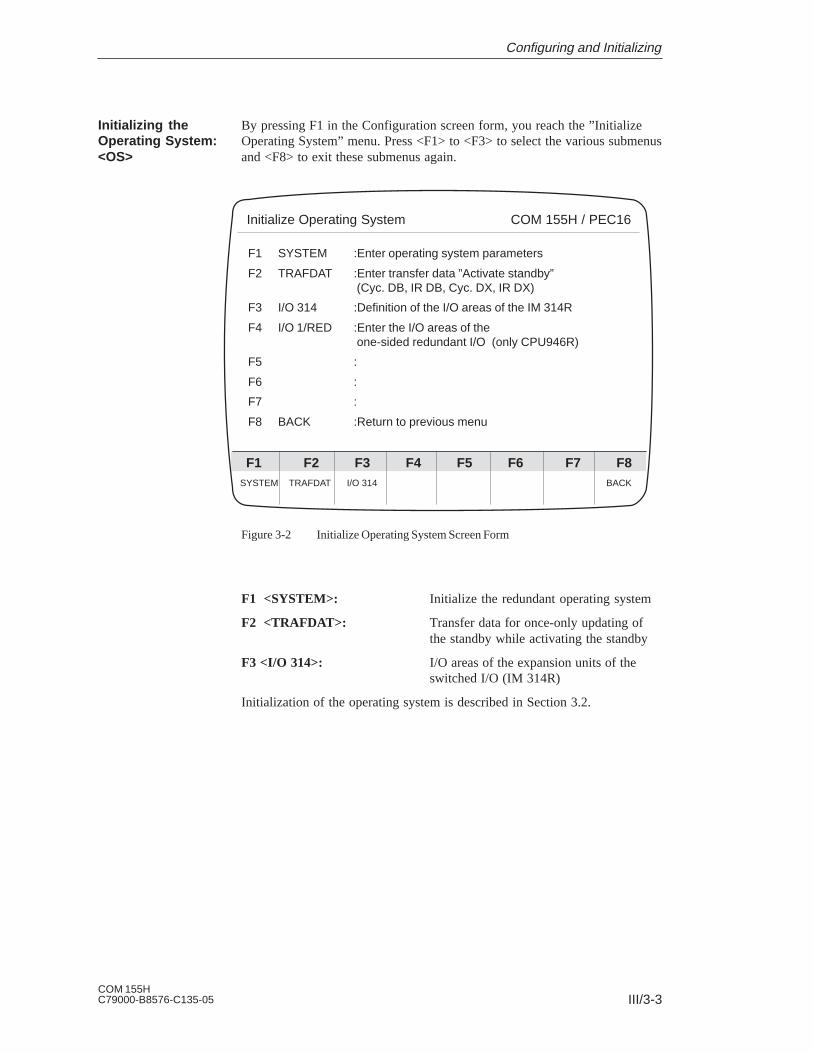
III/3-3COM 155HC79000-B8576-C135-05
By pressing F1 in the Configuration screen form, you reach the ”InitializeOperating System” menu. Press <F1> to <F3> to select the various submenusand <F8> to exit these submenus again.
SYSTEM TRAFDAT I/O 314 BACK
Initialize Operating System COM 155H / PEC16
F6F5F4F3F2F1 F7 F8
F1 SYSTEM :Enter operating system parameters
F2 TRAFDAT :Enter transfer data ”Activate standby” (Cyc. DB, IR DB, Cyc. DX, IR DX)
F3 I/O 314 :Definition of the I/O areas of the IM 314R
F4 I/O 1/RED :Enter the I/O areas of the one-sided redundant I/O (only CPU946R)
F5 :
F6 :
F7 :
F8 BACK :Return to previous menu
Figure 3-2 Initialize Operating System Screen Form
F1 <SYSTEM>: Initialize the redundant operating system
F2 <TRAFDAT>: Transfer data for once-only updating ofthe standby while activating the standby
F3 <I/O 314>: I/O areas of the expansion units of theswitched I/O (IM 314R)
Initialization of the operating system is described in Section 3.2.
Initializing theOperating System:<OS>
Configuring and Initializing

III/3-4COM 155H
C79000-B8576-C135-05
If you press F2 in the COM 155H Configuration Functions screen form, thebasic screen form for configuring the I/Os appears on the programmer. Selectone of the keys F1 to F5 to enter your configuration data for the digital andanalog inputs and outputs and the CPs/IPs.
DI DQ AI AQ CP/IP BACK
Configuration of the I/Os COM 155H / PEC16
F6F5F4F3F2F1 F7 F8
F1 DI :Configure digital inputs
F2 DQ :Configure digital outputs
F3 AI :Configure analog inputs
F4 AQ :Configure analog outputs
F5 CP/IP :Configure CP/IP interfaces
F6 :
F7 :
F8 BACK :Return to previous menu
Figure 3-3 Configuration of the I/Os Screen Form
Initialization of the operating system is described in Section 3.2.
Configuring theI/Os: <IOCONF>
Configuring and Initializing

III/3-5COM 155HC79000-B8576-C135-05
3.2 Initializing the Operating SystemF1: <SYSTEM> (in the Initialize Operating System Basic Screen Form)
You enter the relevant data for the H operating system in this screen form. Ifyou have not loaded a DX 1 in the programmer memory (see F7 <AUXFCT> in the System Handling menu), the data input fields have defaultvalues that you can accept or modify as required.
If DX 1 has already been loaded into the programmer memory, the valuesinitialized appear in the input fields. These can also be modified if necessary.
BACK
Initialize Operating System COM 155H / PEC16
F6F5F4F3F2F1 F7 F8
Behavior following RAM/PIQ comparison error:: 00: Error search mode assume master value1: Standby stop assume master value2: Error search mode delete odd bits (PIQ)3: Standby stop delete odd bits (PIQ)4: Collective stop
No. of test slices (n*2ms) (1...20): 1H error DB number (2...255): 3RAM DB for variable data (2...255): 4H system flag word (0...254): 0Time stamp / F doubleword (SEC/0..252): SECStandard discrepancy time (0.02s...320.00s): 0.05sDQ readback delay (0.02s...1.00s): 0.02sIR DI byte available (Y/N): N
Figure 3-4 Initialize Operating System Screen Form
In the case of ”RAM or PIQ comparison errors”, you can configure thefollowing five operating system responses:
1. Master continues to operate unchanged and the standby enters the errorsearch mode (default).
2. Master continues to operate unchanged, standby enters the STOP mode.
3. In the case of PIQ comparison error, the master sets the non-identical bitto 0, and the standby enters the error search mode;In the case of a RAM comparison error, the master leaves thenon-identical bit unchanged, and the standby enters the error searchmode.
Operating SystemParameters
RAM/PIQComparison Error
Configuring and Initializing

III/3-6COM 155H
C79000-B8576-C135-05
4. In the case of a PIQ comparison error, the master sets the non-identical bitto 0, and the standby enters the STOP mode;In the case of a RAM comparison error, the master leaves thenon-identical bit unchanged, and the standby enters the STOP mode.
5. Both subunits enter the STOP mode.
If a RAM or PIQ comparison error has been caused by a ”stuck at 0/1” error,the self-test locates the defective side immediately and sets it to STOP withan error message. Otherwise, the operating system reacts according to theconfiguration.
Position the cursor at the input field whose value you wish to change,enter the new value there and confirm by pressing <INSERT> or<RETURN>.
Use only permissible values; these are given in parentheses. IfCOM 155H detects a wrong input, the error message ”INVALIDPARAMETER(S)” appears. Now enter a correct value or confirm thevalue suggested by COM 155H.
Number of test slices:
Here you must enter the number of test slices that are to be used within aPLC scan cycle for processing the self-test routines. You can enter anynumber between 1 and 20.
Processing of a test slice takes 2 ms. The more test slices you process, theshorter the error detection time will be; however, the scan cycle time isincreased accordingly.
H error DB number (number of error data block in the H system):
This field is for a DB number anywhere between 3 and 255. The H operatingsystem needs this data block to manage H system errors. You can read out thedata block with COM 155H support (see Section 5.2).
If you enter a number that has already been used for the RAM data block, themessage
”DB NUMBER ASSIGNED”
will appear.
RAM DB for variable data
Here you can also enter any data block number between 3 and 255. Thesystem program requires this data block to manage redundancy-specificvalues. It must be in the RAM.
The length of this data block depends on the scope of your systemconfiguration and varies between one word and 32 Kwords.
If you enter a number already used for the H error data block, the message
”DB NUMBER ASSIGNED”
will appear.
Operating System:Explanation ofParameters
Configuring and Initializing

III/3-7COM 155HC79000-B8576-C135-05
H system flag word
Here you can enter a flag word between 2 and 254. One byte of this word isreserved for redundancy-specific status information entered by the Hoperating system. The second byte is reserved for control information thatcan be set by the user in his STEP 5 program.
Please refer to Section 8.5 of the S5-155H Programmable ControllerInstructions for information on the structure of the H system flag word. If thevalue you have entered coincides with the value entered for the flagdoubleword, the entry will be rejected with the message
”DOUBLE FLAG ASSIGNMENT”
Time stamp F doubleword
If you specify SEC (time stamp: year month day hour minute second) here asthe parameter, the CPU real-time clock (with data and time of day) isautomatically entered in the time stamp of the H error DB in the event of anerror.
If you specify any flag doubleword between 0 and 255, the information inthis doubleword is supplied to the time stamp in the H error DBautomatically if an error message is entered there.
You can store the identifiers (for example, cycle counter, sequencer, etc.) inthis flag doubleword.
Please refer to Section 8.3 of the S5-155H Programmable ControllerInstructions for information on the H flag doubleword.
If the value you enter coincides with the value entered for the H system flagword, your entry will be rejected with the message
”DOUBLE FLAG ASSIGNMENT”
Standard discrepancy time
Redundant digital inputs and redundant analog inputs may have differentsignal states or input values over a relatively short time. By specifying a”discrepancy time”, you can determine how long the H system is to toleratesuch different signal states. A discrepancy time of between 0.01 and 320 s ispermissible.
The standard discrepancy time specified in the Initialize Operating Systemscreen form is displayed as default in the Configuration of the I/Os screenforms.
Proceed as follows when entering the time:
– Enter the time value before the decimal point
– Press <RETURN>
– Enter the time value after the decimal point
– Press <RETURN>
IMPORTANTThis procedure applies to all time entries in COM 155H!
Configuring and Initializing
III/3-8COM 155H
C79000-B8576-C135-05
Readback delay
The various digital output modules have different signal propagation delays.For this reason, you must specify here the time by which the reading in of thereadback DIs (digital inputs) is to be delayed.
This time then applies to all redundant digital outputs (see Readback delaytimes table in Section 11.3 of the S5-155H Instructions).
When entering the time value, please proceed as described above.
IR DI byte available
Here you specify whether the input byte IB 0 (process-interrupt-drivenprogram processing) is to be used as an interrupt DI byte or not.
Note:IB 0 can only be operated as an interrupt DI in switched or redundantmode!
The maximum discrepancy time is 1.00 s. The discrepancy time specified forbit 0.0 applies to all eight inputs.
Configuring and Initializing

III/3-9COM 155HC79000-B8576-C135-05
3.3 Initializing Activation of the StandbyF2: <TRAFDAT> (in the Initialize Operating System Basic Screen Form)
Use this form to enter all the data blocks that are to be transferred from themaster to the standby when the latter is activated. These are the DB and DXdata blocks.
F1 CYC. DB :Configuration for transfer of DBs processed in the cyclic program part
F2 CYC. DX :Configuration for transfer of DXs processed in the cyclic program part
F3 IR DB :Configuration for transfer of DBs processed in the interrupt program part
F4 IR DX :Configuration for transfer of DXs processed in the interrupt program part
F5 :F6 :F7 :F8 BACK :Return to previous menu
CYC. DB CYC. DX IR DB IR DX BACK
Transfer Data ”Activate Standby” COM 155H / PEC16
F6F5F4F3F2F1 F7 F8
Figure 3-5 Transfer Data Screen Form
The contents of the DB and DX data blocks can be modified by the userprogram. A distinction is made between data blocks processed in the cyclicprogram (for example, DB or DX from OB 1 and the blocks called fromthere), and data blocks processed in timed interrupts and process interrupts(for example DB or DX from OB 13, timed interrupt).
Data blocks that occur on both levels need only be entered in the interruptDB/DX screen form.
The more data blocks you enter in these four screen forms, the longer theonce-only update of the standby in the activation phase will take.
The more data blocks that have been entered in the interrupt DB/DX, thelonger the interrupts are disabled by updating.
If the H error DB for the RAM DB is in one of the lists, it is automaticallydeleted from the list by COM 155H.
Transfer Data forActivating Standby
Configuring and Initializing
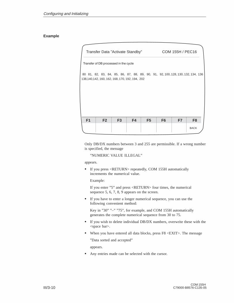
III/3-10COM 155H
C79000-B8576-C135-05
80 81, 82, 83, 84, 85, 86, 87, 88, 89, 90, 91, 92, 100, 128, 130, 132, 134, 136
138,140,142, 160, 162, 168, 170, 192, 194, 202
BACK
Transfer Data ”Activate Standby” COM 155H / PEC16
F6F5F4F3F2F1 F7 F8
Only DB/DX numbers between 3 and 255 are permissible. If a wrong numberis specified, the message
”NUMERIC VALUE ILLEGAL”
appears.
If you press <RETURN> repeatedly, COM 155H automaticallyincrements the numerical value.
Example:
If you enter ”5” and press <RETURN> four times, the numericalsequence 5, 6, 7, 8, 9 appears on the screen.
If you have to enter a longer numerical sequence, you can use thefollowing convenient method:
Key in ”30” ”–” ”75”, for example, and COM 155H automaticallygenerates the complete numerical sequence from 30 to 75.
If you wish to delete individual DB/DX numbers, overwrite these with the<space bar>.
When you have entered all data blocks, press F8 <EXIT>. The message
”Data sorted and accepted”
appears.
Any entries made can be selected with the cursor.
Example
Configuring and Initializing

III/3-11COM 155HC79000-B8576-C135-05
3.4 Initializing the I/O AreasF3: <I/O 314> (in the Initialize Operating System Basic Screen Form)
This screen form is used to define the I/O areas of the IM 314R (switchedI/O). The area numbers specified in the IM 314R I/O form automaticallyassign the relevant I/O area to the IM 314R and, consequently, to theassociated expansion units.
Set System Size COM 155H / PEC16
Enter area number! ”N” means not reserved
I/O area of EU number 0 : 0 P area FF000H ... FF0FFHI/O area of EU number 1 : 0 P area FF000H ... FF0FFHI/O area of EU number 2 : N not reservedI/O area of EU number 3 : N not reservedI/O area of EU number 4 : 1 O area FF100H ... FF1FFHI/O area of EU number 5 : N not reservedI/O area of EU number 6 : N not reservedI/O area of EU number 7 : N not reservedI/O area of EU number 8 : N not reservedI/O area of EU number 9 : N not reservedI/O area of EU number 10 : N not reservedI/O area of EU number 11 : N not reservedI/O area of EU number 12 : N not reservedI/O area of EU number 13 : N not reservedI/O area of EU number 14 : N not reservedI/O area of EU number 15 : N not reserved
SELECT BACK
F6F5F4F3F2F1 F7 F8
Figure 3-6 IM 314R I/O Screen Form
Only block numbers 0, 1, 3, 12 and 13 are permissible. If you specify awrong number, the message
”INVALID PARAMETER(S)”
appears.
When you press F8 <EXIT>, the message
”Data accepted”
appears to confirm this.
Area Parameters ofthe Switched I/O inthe EU
Configuring and Initializing

III/3-12COM 155H
C79000-B8576-C135-05
Configuring and Initializing

III/4-1COM 155HC79000-B8576-C135-05
Configuring the I/O
The F1 to F5 keys in the I/O basic screen form take you into the individualI/O forms in which you can enter your configuration data for the digital andanalog inputs/outputs, as well as the CPs and IPs (see Section 4.2).
4
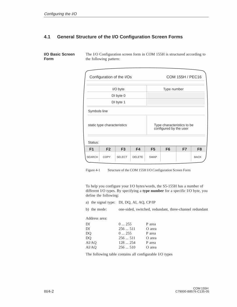
III/4-2COM 155H
C79000-B8576-C135-05
4.1 General Structure of the I/O Configuration Screen Forms
The I/O Configuration screen form in COM 155H is structured according tothe following pattern:
I/O byte Type number
DI byte 0
DI byte 1
Symbols line
static type characteristics Type characteristics to beconfigured by the user
Status:
SEARCH COPY SELECT DELETE SWAP BACK
Configuration of the I/Os COM 155H / PEC16
F6F5F4F3F2F1 F7 F8
Figure 4-1 Structure of the COM 155H I/O Configuration Screen Form
To help you configure your I/O bytes/words, the S5-155H has a number ofdifferent I/O types. By specifying a type number for a specific I/O byte, youdefine the following:
a) the signal type: DI, DQ, AI, AQ, CP/IP
b) the mode: one-sided, switched, redundant, three-channel redundant
Address area:
DI 0 ... 255 P areaDI 256 ... 511 O areaDQ 0 ... 255 P areaDQ 256 ... 511 O areaAI/AQ 128 ... 254 P areaAI/AQ 256 ... 510 O area
The following table contains all configurable I/O types
I/O Basic ScreenForm
Configuring the I/O

III/4-3COM 155HC79000-B8576-C135-05
Table 2-1 Configurable I/O Types
Type No. Meaning Fault Tolerance
1234
891011
13141516
18192021
2425
DI byte 1-channelDI byte switchedDI byte 2-channel redundantDI byte 3-channel redundant
DQ byte 1-channelDQ byte switchedDQ byte 2-channel redundantDQ byte 2-channel redundant
AI channel 1-channelAI channel switchedAI channel 2-channel redundantAI channel 3-channel redundant
AQ channel 1-channelAQ channel switchedAQ channel redundantAQ channel redundantwith error locationCP/IP 1-channelCP/IP switched
Standard (as for S5-155U)EnhancedHighHighest
StandardEnhancedHighHigh, with 3 R-DIs
StandardEnhancedHighHighest
StandardEnhancedHigh (without error location)High
StandardEnhanced
In the top left corner of the Configuration of the I/Os screen form (see Fig.4-1), the I/O byte/word or the interface number is displayed and, to the rightof this, the associated type. The next I/O bytes/words follow underneath.
When a specific configuration screen form (DI, DQ, AI etc.) is selected, thecursor is located in the Type number field.
If you press F3, the lowest associated type number in each case isdisplayed (”1” for DI, ”8” for DQ, etc.)
You can select another type by pressing F3 <SELECT> (e.g. for DI ringselection 1, 2, 3, 4, 1, 2, 3, 4, 1, etc.)
The symbols line indicates the I/O byte or word the cursor is currentlypositioned at (for example, digital input 2.3 or analog output 128). Inaddition, the associated abbreviated symbol (eight characters) and thenon-abbreviated symbol (14 characters) are indicated here, provided youhave created them (for the digital I/O area 0 to 127).
Example:
Symbols line: Valve 1 Valves for pumps 0 to 7
Confirm the type by pressing <RETURN> or <INSERT>. The associatedcharacteristics field appears. The cursor is located in the right-hand halfof this field.
Displays in theConfigurationScreen Form
Configuring the I/O

III/4-4COM 155H
C79000-B8576-C135-05
The bottom half of the Configuration form contains the characteristics fieldin which the characteristics of the current type are displayed. The left-handfield contains the fixed or static characteristics assigned to a particular type.The right-hand field contains the characteristics to be configured by the userfor the current type.
Enter the necessary data and confirm each entry with <RETURN> or<INSERT>.
When you have made your last entry, the cursor will jump back up to the lineof the next byte/word.
The desired byte or word number can be selected with the <Cursor up>and <Cursor down> keys (scroll function).
When you have configured your system and stored it in the programmermemory, bytes/words that have already been configured will be automaticallydisplayed when you make entries. This applies also to inputs or outputalready reserved as L-DI, L-DQ and R-DI. You can then no longer specify atype number.
The current processing status (”TYPE INPUT” or ”SWAP”, for instance) isdisplayed in the left-hand half of the status and error line; error messagesappear in the right-hand half.
F1: <SEARCH>
This function enables you to select a random byte, word or interface numberquickly and without having to use the cursor.
Press <F1> and enter the byte/word or interface number you are lookingfor. The cursor then appears in the line of the specified byte/word or thespecified interface number.
F2: <COPY>
This function allows you to copy the configuration of a particular byte/wordor interface number to another byte/word or another interface number.
After you have entered the desired byte number(s), the message
”DESTINATION END AT BYTE x COPY?”
appears on the screen.
Confirm with the <INSERT> key.
If you make an illegal specification, COM 155H aborts and an error messageappears, for example:
”DESTIN. AREA IN SOURCE AREA” or
”READBACK I/O: ABORT”.
The following cannot be copied: L-DI L-DQ R-DI DI type 4 DQ types 10 and 11
Processing the I/OConfigurationScreen Form
Keys in theConfigurationScreen Form
Configuring the I/O

III/4-5COM 155HC79000-B8576-C135-05
AI type 16 AQ type 21
F3: <SELECT>
When the cursor is in the top-right Type number field, you can use thisspecification to select all possible I/O types (for example, DI ring selection1, 2, 3, 4, 1, 2, 3, 4, 1, etc.). Confirm the type number displayed with the<RETURN> key. Further, you can use the <SELECT> key for makingselections in the characteristics field (for instance, AQ type 21).
F4: <DELETE>
This function deletes one or more bytes/words in your configuration. Whenyou have entered the byte number(s), the question ”DELETE?” appears onthe screen.
Confirm with the <INSERT> key or press <ESC>.
If you want to delete a number of successive bytes, you can specify, forexample, ”10” ”-” ”15”. COM 155H then deletes bytes 10, 11, 12, 13, 14and 15.
F5: <SWAP>
This function swaps configuration data between individual bytes words.
The following message appears on the screen:
”DESTINATION END IN BYTE x ABORT?”
Confirm with <INSERT> or press <ESC>.
The following cannot be swapped:
L-DI L-DQ COM 155H generates the error message R-DI ”READBACK I/O: ABORT”
DI types 1+2 in the analog area (AI and AQ screen forms, 128 to 254)
DQ types 8+9 in the analog area (AI and AQ screen forms, 128 to 254)
Configuring the I/O

III/4-6COM 155H
C79000-B8576-C135-05
4.2 Structure of the Individual I/O Configuration Screen Forms
When configuring your I/Os, please refer to the relevant chapter in theS5-155H Instructions.
<DI> (in the I/O basic screen form)
The COM 155H Configuration of the I/Os Type 1 form appears on thescreen.
I/O byte Type number
DI byte 0
DI byte 1
Digital input 0 IB 0
Type number : 1 Subunit (A/B):No. of I/O chan. : 1Fault tolerance : standard
DI in one-channel I/O
Status: TYPE INPUT
SEARCH COPY SELECT DELETE SWAP BACK
Configuration of the I/Os COM 155H / PEC16
F6F5F4F3F2F1 F7 F8
1
Figure 4-2 I/O Configuration Screen Form Type 1
All you have to do here is program the subunit in which the DI is operated.
Using <F3>, you can preselect the individual type numbers. These are shownon the screen in plaintext. This is valid for the entire configuration of the I/O.
Digital Inputs: F1
Configuring the I/O

III/4-7COM 155HC79000-B8576-C135-05
I/O byte
DI byte 0
DI byte 1
Digital input 0 IB 0
Type number : 2No. of I/O chan. : 1Fault tolerance : enhanced
DI in switched I/O
Status: TYPE INPUT
SEARCH COPY SELECT DELETE SWAP BACK
Configuration of the I/Os COM 155H / PEC16
F6F5F4F3F2F1 F7 F8
2
Type number
Figure 4-3 I/O Configuration Screen Form Type 2
No further initialization is necessary here.
Type number : 3 L-DQ byte/bit (0.0...255.7): .No. of I/O chan. : 2 L-DI byte/bit (0.0...255.7): .Fault tolerance : high Discrepancy times (0.02 s...320.00 s)
Bit 0: 0.05s Bit 4: 0.05sReadback module required: Bit 1: 0.05s Bit 5: 0.05swith/without L-DI/L-DQ Bit 2: 0.05s Bit 6: 0.05s
Bit 3: 0.05s Bit 7: 0.05s
DI in redundant I/O
Status: TYPE INPUT
I/O byte
DI byte 0
DI byte 1
SEARCH COPY SELECT DELETE SWAP BACK
Configuration of the I/Os COM 155H / PEC16
F6F5F4F3F2F1 F7 F8
3
Type number
Figure 4-4 I/O Configuration Screen Form Type 3
Configuring the I/O

III/4-8COM 155H
C79000-B8576-C135-05
Type number : 4 3rd DI chan. addr. (0...255) :No. of I/O chan. : 3 3rd DI channel in I/O :Fault tolerance : highest (1:PLC A, 2:PLC B, 3:P swit., 4:O swit.)
No. of sensors (1 or 3) :Discrepancy times (0.02s...320.00s)Bit 0: 0.05s Bit 4: 0.05sBit 1: 0.05s Bit 5: 0.05s
DI in redundant I/O Bit 2: 0.05s Bit 6: 0.05swith 3rd channel Bit 3: 0.05s Bit 7: 0.05s
Status: TYPE INPUT
I/O byte
DI byte 0
DI byte 1
SEARCH COPY SELECT DELETE SWAP BACK
Configuration of the I/Os COM 155H / PEC16
F6F5F4F3F2F1 F7 F8
4
Type number
Figure 4-5 I/O Configuration Screen Form Type 4
Locating DI, locating DQ:You can use type 3 with or without error locating DI (L-DI) or L-DQ: If youuse L-DI or L-DQ, the DI can be used as ”NON-STOP DI”.
Note:Several redundant DIs can use the same locating facility (L-DI/L-DQ).
Discrepancy timesSince redundant digital inputs may have different signal states over acomparatively short period of time, you can use COM 155H to configurehow long these different signal states can be tolerated.
If the configured discrepancy time is smaller than a PLC cycle time, thediscrepancy time is set within the CPU to a PLC cycle time during cyclicprocessing (apart from with redundant process interrupts).
Various discrepancy times can be assigned to the individual bits of the DI.You can configure discrepancy times of between 10 ms and 320 ms in stepsof 10 ms. The configured standard discrepancy time in the COM 155H”Initialize Operating System” screen form is the default value.
Legend: DI
Configuring the I/O
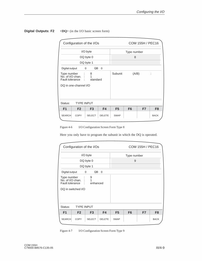
III/4-9COM 155HC79000-B8576-C135-05
<DQ> (in the I/O basic screen form)
Type number : 8 Subunit (A/B) :No. of I/O chan. : 1Fault tolerance : standard
DQ in one-channel I/O
Status: TYPE INPUT
I/O byte
DQ byte 0
DQ byte 1
SEARCH COPY SELECT DELETE SWAP BACK
Configuration of the I/Os COM 155H / PEC16
F6F5F4F3F2F1 F7 F8
8
Type number
Figure 4-6 I/O Configuration Screen Form Type 8
Here you only have to program the subunit in which the DQ is operated.
Type number : 9No. of I/O chan. : 1Fault tolerance : enhanced
DQ in switched I/O
Status: TYPE INPUT
I/O byte
DQ byte 0
DQ byte 1
SEARCH COPY SELECT DELETE SWAP BACK
Configuration of the I/Os COM 155H / PEC16
F6F5F4F3F2F1 F7 F8
9
Type number
Figure 4-7 I/O Configuration Screen Form Type 9
Digital Outputs: F2
Configuring the I/O
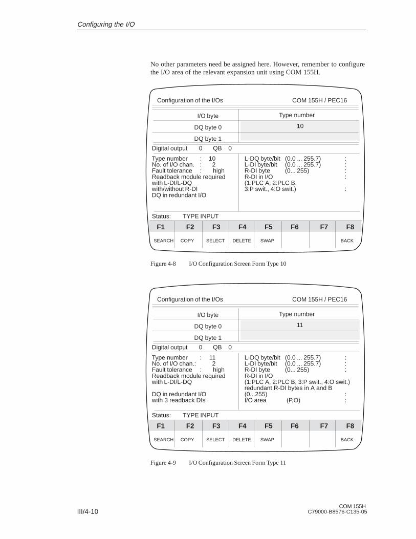
III/4-10COM 155H
C79000-B8576-C135-05
No other parameters need be assigned here. However, remember to configurethe I/O area of the relevant expansion unit using COM 155H.
Digital output 0 QB 0
Type number : 10 L-DQ byte/bit (0.0 ... 255.7) :No. of I/O chan. : 2 L-DI byte/bit (0.0 ... 255.7) :Fault tolerance : high R-DI byte (0... 255) :Readback module required R-DI in I/O :with L-DI/L-DQ (1:PLC A, 2:PLC B,with/without R-DI 3:P swit., 4:O swit.) :DQ in redundant I/O
Status: TYPE INPUT
I/O byte
DQ byte 0
DQ byte 1
SEARCH COPY SELECT DELETE SWAP BACK
Configuration of the I/Os COM 155H / PEC16
F6F5F4F3F2F1 F7 F8
10
Type number
Figure 4-8 I/O Configuration Screen Form Type 10
Digital output 0 QB 0
Type number : 11 L-DQ byte/bit (0.0 ... 255.7) :No. of I/O chan.: 2 L-DI byte/bit (0.0 ... 255.7) :Fault tolerance : high R-DI byte (0... 255) :Readback module required R-DI in I/Owith L-DI/L-DQ (1:PLC A, 2:PLC B, 3:P swit., 4:O swit.)
redundant R-DI bytes in A and BDQ in redundant I/O (0...255) :with 3 readback DIs I/O area (P,O) :
Status: TYPE INPUT
I/O byte
DQ byte 0
DQ byte 1
SEARCH COPY SELECT DELETE SWAP BACK
Configuration of the I/Os COM 155H / PEC16
F6F5F4F3F2F1 F7 F8
11
Type number
Figure 4-9 I/O Configuration Screen Form Type 11
Configuring the I/O

III/4-11COM 155HC79000-B8576-C135-05
Locating DI (L-DI), locating DQ (L-DQ):see DI in I/O Configuration Screen Form Type 3
Readback DI (R-DI)A readback DI must be specified for each redundant DQ, otherwise an errorcannot be detected.
You must also specify a readback delay in the COM 155H ”InitializeOperating System” screen form for the readback DIs. This takes the differentsignal propagation delays of the various digital output modules into account.
Readback DI in the I/OIn this field, you specify the type of I/O in which the readback DI is to beoperated.
1. The readback DI is one-sided: Subunit A.
2. The readback DI is one-sided: Subunit B.
3. The readback DI is switched: P area
4. The readback DI is switched: O area
Redundant readback DIFor the redundant DQ type 11, the redundant readback DI bytes must also bespecified.
<AI> (in the I/O basic screen form)
Analog input 0 PW 128
Type number : 13No. of I/O chan. : 1No. of sensors : 1Fault tolerance : standard
AI in one-channel I/O
Status: TYPE INPUT
I/O word
AI word 128
AI word 130
SEARCH COPY SELECT DELETE SWAP BACK
Configuration of the I/Os COM 155H / PEC16
F6F5F4F3F2F1 F7 F8
Subunit (A/B)
13
Type number
Figure 4-10 I/O Configuration Screen Form Type 13
Here you must program the subunit in which the AI is operated.
Legend: DQ
Analog Inputs: F3
Configuring the I/O

III/4-12COM 155H
C79000-B8576-C135-05
Analog input 0 PW 128
Type number : 14No. of I/O chan. : 1No. of sensors : 1Fault tolerance : enhanced
AI in switched I/O
Status: TYPE INPUT
I/O word
AI word 128
AI word 130
SEARCH COPY SELECT DELETE SWAP BACK
Configuration of the I/Os COM 155H / PEC16
F6F5F4F3F2F1 F7 F8
14
Type number
Figure 4-11 I/O Configuration Screen Form Type 14
No other parameters need be assigned.
I/O word
AI word 128
AI word 130
Analog input 0 PW 128
Type number : 15 Discrepancy value absolute : 50No. of I/O chan. : 2 (+0 ... +4096)No. of sensors : 1 or 2 Discr. value relative (0..100 %) : 5 %Fault tolerance : high Preferred value (1:min, 2:max) : 2
lower limit (-200%..+200%) :- 0 %upper limit (-200%..+200%) :+100%
AI in redundant I/O Discrepancy times : 0.50s(0.02 s ... 320.00 s)
Status: TYPE INPUT
SEARCH COPY SELECT DELETE SWAP BACK
Configuration of the I/Os COM 155H / PEC16
F6F5F4F3F2F1 F7 F8
15
Type number
Figure 4-12 I/O Configuration Screen Form Type 15
Configuring the I/O

III/4-13COM 155HC79000-B8576-C135-05
Analog input 0 PW 128
Type number : 16 Discrep. value absolute (0..4096) : 50No. of I/O chan. : 3 Discrep. value relative (0..100 %) : 5 %No. of sensors: 1 or 3 3rd AI chan. (128/0...254) :Fault tolerance : highest 3rd AI channel in I/O
(1: PLC A, 2: PLC B, 3: P swit., 4:O swit.)lower limit (-200%..+200%) : - 0 %
AI in redundant I/O upper limit (-200%..+200%) : +100 %with 3rd AI channel Discrep. times (0.02s..320.0s) : 0.50 s
Status: TYPE INPUT
I/O word
AI word 128
AI word 130
SEARCH COPY SELECT DELETE SWAP BACK
Configuration of the I/Os COM 155H / PEC16
F6F5F4F3F2F1 F7 F8
16
Type number
Figure 4-13 I/O Configuration Screen Form Type 16
Absolute/relative discrepancy value:Enter an absolute value ABS (decimal number) and a relative value REL(percentage).
The 155H operating system calculates the permissible analog valuediscrepancy DPERM according to the following formula:
100
REL * RAWV (max)
where for type 15 RAWV (max) is the greater of the two instantaneousanalog values.
where for type 16 RAWV is the middle of the three instantaneous analogvalues.
Preferred value (type 15):Specify here whether the 155H operating system is to give preference to themaximum or minimum value in the case of a discrepancy between the analogvalues.
Legend: AI (Types15 and 16)
Configuring the I/O

III/4-14COM 155H
C79000-B8576-C135-05
Lower, upper limit (type 15/16):The upper and lower limit values define a range for the analog value outsidewhich the 155H operating system reports an error.
200% corresponds to 4096
100% corresponds to 2048
0% corresponds to 0
-100% corresponds to -2048
-200% corresponds to -4096
applies to voltage and current
Discrepancy time (type 15/16):See Configuration screen form DI type 3
Configuring the I/O

III/4-15COM 155HC79000-B8576-C135-05
<AQ> (in the I/O basic screen form)
Analog output 0 PW 128
Type number : 18 Subunit (A/B) :No. of I/O chan. : 1Fault tolerance : standard
AQ in one-channel I/O
Status: TYPE INPUT
I/O word
AQ word 128
AQ word 130
SEARCH COPY SELECT DELETE SWAP BACK
Configuration of the I/Os COM 155H / PEC16
F6F5F4F3F2F1 F7 F8
18
Type number
Figure 4-14 I/O Configuration Screen Form Type 18
Here you must specify the subunit in which the AQ is operated.
Analog output 0 PW 128
Type number : 19No. of I/O chan. : 1Fault tolerance : enhanced
AQ in switched I/O
Status: TYPE INPUT
I/O word
AQ word 132
AQ word 134
SEARCH COPY SELECT DELETE SWAP BACK
Configuration of the I/Os COM 155H / PEC16
F6F5F4F3F2F1 F7 F8
19
Type number
Figure 4-15 I/O Configuration Screen Form Type 19
No other parameter settings are required here.
Analog Outputs:F4
Configuring the I/O

III/4-16COM 155H
C79000-B8576-C135-05
Analog output 0 PW 128
Type number : 20No. of I/O chan. : 2Fault tolerance : high
AQ in redundant I/O
Status: TYPE INPUT
I/O word
AQ word 250
AQ word 252
SEARCH COPY SELECT DELETE SWAP BACK
Configuration of the I/Os COM 155H / PEC16
F6F5F4F3F2F1 F7 F8
20
Type number
Figure 4-16 I/O Configuration Screen Form Type 20
The redundant analog output type 20 cannot locate errors.
I/O word
AQ word 128
AQ word 130
Analog output 0 PW 128Type number : 21 L-DQ byte/bit (0.0...255.7) : 0.0No. of I/O chan. : 2 L-DQ in area (P/O) : PFault tolerance : high R-AI word (O:0..254; P:128..254) : 240Error locating : yes R-AI in I/O (F3: SELECT)AQ in redundant I/O Discrepancy value (abs.)(0..1023): 40
Readback delay (0.02s..320.00s) : 0.05sIndic. update in disc time (1..10) : 2AQ output type (F3: SELECT) : 4-20 mAR-AI module (F3: SELECT):460-4UA..
Status: TYPE INPUT
SEARCH COPY SELECT DELETE SWAP BACK
Configuration of the I/Os COM 155H / PEC16
F6F5F4F3F2F1 F7 F8
21
Type number
Figure 4-17 I/O Configuration Screen Form Type 21
Configuring the I/O

III/4-17COM 155HC79000-B8576-C135-05
The redundant analog output type 21 can locate errors and remedy them.
Channel 0 must always be configured before the other channels (1 - 7).
L-DQ byte/bitArea: P or O (the L-DQ byte and bit lie in subunit A and B at the sameaddress).
1. An L-DQ byte which is configured for a two-channel AQ may not also beused elsewhere (not even as the L-DQ for DI or DQ), because if a subunitfails, the byte on the intact side is written with 0FFh.
2. Assignment of channel number to L-DQ bit number is fixed:
Address AQ
2 modulo 8L-DQ bit no.
Address AQ = base address + channel no. *2Example:Base address = 128 and channel no. = 5:→ address AQ = 138, L-DQ bit no. = 5. Base address = 200 and channel no. = 3: → address AQ = 206, L-DQ bit no. = 7.
L-DQ Bit Address of AQ Channel
0 128 144 160 176 192 208 224 240
1 130 146 162 178 194 210 226 242
2 132 148 164 180 196 212 228 244
3 134 150 166 182 198 214 230 246
4 136 152 168 184 200 216 232 248
5 138 154 170 186 202 218 234 250
6 140 156 172 188 204 220 236 252
7 142 158 174 190 206 222 238 254
3. Free L-DQ bits may not be used elsewhere.
R-AI addressArea: P or O I/O area: one-sided in A or B or switched.
(Permissible) discrepancy value (absolute)Suggestion for systems with minimal failure rate: 40
Readback delayDefault: 0.05 sReadback delay time to be configured = R-AI encoding time or R-AI cycle time + possibly ET 200 bus cycle time.
Legend: AQType 21
Configuring the I/O

III/4-18COM 155H
C79000-B8576-C135-05
Indic. no. of updates (AQ) (FB calls and transfer direct access T PW/T OW)per readback delay time (AQ) (1...10)Default: 10The value for ”Indic. update in readback delay time” is:N = readback delay time/AQ update interval.Example 1 for ”Indic. update in readback delay time” = N
– AI 463: R-AI encoding time = 50 ms
– AQ updates every 10 ms (FB calls or T PW instructions on AQ)→ N 50/10 = 5
U Periphery:
The FB 41 : H-RLG : AA can be used for the following modules:
AQ modules:
6ES5 470-4UA..
6ES5 470-4UB
6ES5 470-4UC
Readback AI modules:
6ES5 466-3LA.. encoding time < 4 ms
As this module has no interference suppression it can only be used as anR-AI if the high-frequency interferences arising on the user side are smallenough.
If the module is used as an R-AI for current outputs, only the 8 differentialinputs may be used.
6ES5 460-4UA.. encoding time < 480 (960) ms
6ES5 463-4U... encoding time < 50 ms, only as R-AI for voltage output
6ES5 465-4UA.. encoding time < 480 (960) ms,
L-DQ modules:
6ES5 458-4UA..
Conditions
Configuring the I/O

III/4-19COM 155HC79000-B8576-C135-05
<CP/IP> (in the I/O basic screen form)
Here you must specify the subunit to which communicationsprocessors/intelligent I/O modules have been assigned.
Interface number 0
Type number : 24 Subunit (A/B) :CP/IP number : 1Fault tolerance : standard
CP/IP in one-channel I/O
Status: TYPE INPUT
Interface number
IF no. 0
IF no. 1
SEARCH COPY SELECT DELETE SWAP BACK
Configuration of the I/Os COM 155H / PEC16
F6F5F4F3F2F1 F7 F8
24
Type number
Figure 4-18 I/O Configuration Screen Form Type 24
Interface number 0
Type number : 25CP/IP number : 1Fault tolerance : enhanced
CP/IP in switched I/O
Status: TYPE INPUT
Interface number
IF no. 0
IF no. 1
SEARCH COPY SELECT DELETE SWAP BACK
Configuration of the I/Os COM 155H / PEC16
F6F5F4F3F2F1 F7 F8
25
Type number
Figure 4-19 I/O Configuration Screen Form Type 25
No other parameter settings are required here.
CP/IP: F5
Configuring the I/O

III/4-20COM 155H
C79000-B8576-C135-05
Configuring the I/O

III/5-1COM 155HC79000-B8576-C135-05
Error Diagnostics and Documentation
The F2 and F4 function keys in the Diagnostics basic form support you whentroubleshooting. You can obtain an overview of the errors that have occurredwith F2 <STAT ERR>, as well as detailed information on each individualerror with F4 <H ERROR>.
If you want to document your configuration, press <F7> in the Main Menu toreach the ”System Handling” menu and then press <F4> to reach the”COM 155H Print Menu”.
5

III/5-2COM 155H
C79000-B8576-C135-05
5.1 Static Error Image of the I/Os
F2 <STAT ERR> in the Diagnostics menu takes you to the basic screen formfor the I/O error image. All messages entered in the STATUS word (= DW 3of the error DB) appear. If, for example, the ”CONFIGURATION ERROR”message appears, there is at least one and possibly several configurationerrors (please refer to the S5-155H Instructions, Section 8.2 ”Structure of theError DB”).
Static Error Image of the I/Os COM 155H / PEC16
DI DQ AI AQ CP/IP COMFLAG EU BACK
F6F5F4F3F2F1 F7 F8
THE FOLLOWING ENTRIES ARE PRESENT:
PARALLEL LINK ERRORI/O ERRORHARDWARE ERROR
Figure 5-1 Basic Screen Form of the I/O Error Image
You can then have the static error image displayed as follows:
Digital inputs <DI>
Digital outputs <DQ>
Analog inputs <AI>
Analog outputs <AQ>
CP and IP modules <CP/IP>
Interprocessor communication input and output flags <COMFLAG>.
I/O Error ImageDisplay
Error Diagnostics and Documentation

III/5-3COM 155HC79000-B8576-C135-05
If you press F1 <DI>, for example, the following screen form will appear:
Static Error Image of the I/Os COM 155H / PEC16
CONTINUE BACK
F6F5F4F3F2F1 F7 F8
Digital inputsPLC connected is subunit A and STANDBY
0
10
20
30
40
50
60
0 21 4 65 9873
AB S
RS
Figure 5-2 DI Error Image Basic Screen Form
F3 <CONTINUE> can be used, until DI 511 is reached. The followingentries are possible:
A Defect in subunit A B Defect in subunit B S Switched defective RA Configured redundant, defect in subunit A RB Configured redundant, defect in subunit B AB Configured redundant, A+B defective 3A 3-channel configured, defect in subunit A 3B 3-channel configured, defect in subunit B 3AB 3-channel configured, A+B defective R-A Readback DI/AI in subunit A defective R-B Readback DI/AI in subunit B defective RS Readback DI/AI in switched I/O defective 3-A 3rd channel in subunit A defective 3-B 3rd channel in subunit B defective 3-S 3rd channel in switched I/O defective L-A Locating DI in subunit A defective L-B Locating DI in subunit B defective L-AB Locating DI in subunit A and B defective
In the above example
Input byte IB 6 in subunit A+B is defective Input byte IB 7 is switched defective Input byte IB 22 readback DI in switched I/O is defective
Error Diagnostics and Documentation
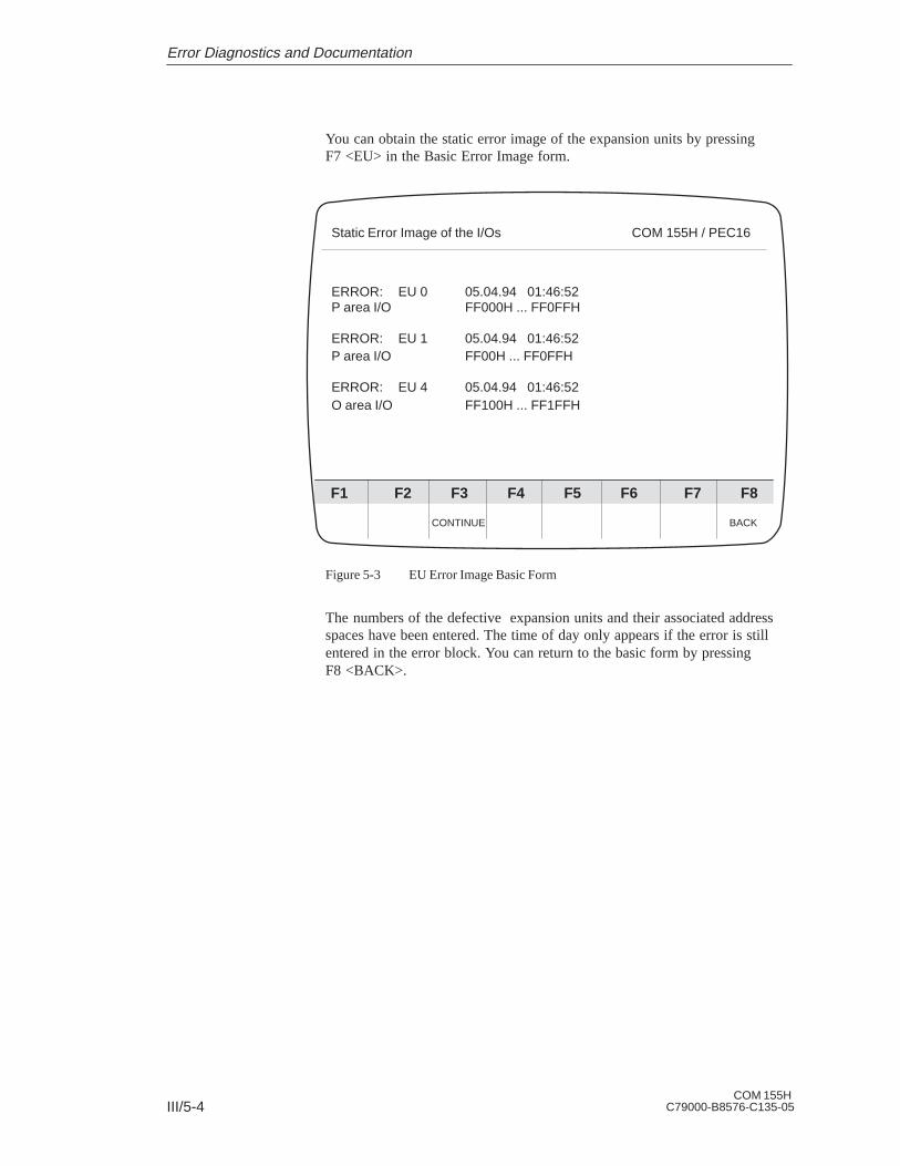
III/5-4COM 155H
C79000-B8576-C135-05
You can obtain the static error image of the expansion units by pressingF7 <EU> in the Basic Error Image form.
Static Error Image of the I/Os COM 155H / PEC16
CONTINUE BACK
F6F5F4F3F2F1 F7 F8
ERROR: EU 0 05.04.94 01:46:52P area I/O FF000H ... FF0FFH
ERROR: EU 1 05.04.94 01:46:52P area I/O FF00H ... FF0FFH
ERROR: EU 4 05.04.94 01:46:52O area I/O FF100H ... FF1FFH
Figure 5-3 EU Error Image Basic Form
The numbers of the defective expansion units and their associated addressspaces have been entered. The time of day only appears if the error is stillentered in the error block. You can return to the basic form by pressingF8 <BACK>.
Error Diagnostics and Documentation

III/5-5COM 155HC79000-B8576-C135-05
5.2 Error Data Block
After pressing F4 <H ERROR> in the Diagnostics Menu, you must specifywhether you wish to read the error data block from the PLC (with F1: on-linediagnostics) or from diskette (with F2: off-line diagnostics):
Error Diagn. with COM 155H COM 155H / PEC16
LOAD PLC LOAD FD PR PLC PR FD BACK
F6F5F4F3F2F1 F7 F8
Program file: B:@@@@@@ST.S5D
F1 LOAD PLC :Load configured error DB from PLC
F2 LOAD FD :Load configured error DB from diskette
F3 :
F4 :
F5 PR PLC :Print error messages from PLC
F6 PR FD :Print error messages from diskette
F7 :
F8 BACK :Return to previous menu
Figure 5-4 Error Diagnostics Screen Form
When you have selected the desired function, the contents of the error DBwill appear on the screen. This applies to both subunits.
F1 <LOAD PLC>:The error DB configured in DX1 is loaded.
If DX1 does not exist (after an overall reset, for example), the standarddefault error DB 3 is loaded. If there is no error DB 3, the programmerprompts you for a DB number. If this DB is also not in the programmablecontroller, the error DB is loaded from the absolute programmable controlleraddress.
F2 <LOAD FD>:The error DB configured in DX1 is loaded from the hard disk or from thediskette drive in the programmer.
F4 <PR PLC>:All errors signalled in the programmable controller are printed in compressedform.
F5 <PR FD>:All reported errors which are in the error DB of the file selected are printedin compressed form. The respective DX1 must also be available in the file.
Calling the ErrorDB
Error Diagnostics and Documentation

III/5-6COM 155H
C79000-B8576-C135-05
Error Diagnostics with COM 155HCOM 155H/PEC16
SUBUNIT B
ERROR RECORD NO. :2 CURRENT ERROR RECORD NO.: 3
Error class : MessageError : 95 : DI MODULE NOT CONFIGUREDTime stamp : 25.04.94 17:16:28DI ADDRESS : F00B DI BYTE NO. :11
SUBUNIT B
ERROR RECORD NO. : 3 CURRENT ERROR RECORD NO.: 3
Error class : PassivationError:51 : TIMEOUT ON OUTPUT MODULESTime stamp : 25.04.94 17:16:32DI ADDRESS : F007 INSTR. CODE: 0000
If several errors occur, the error last entered is displayed first. Each screenform corresponds to an error record in the error DB.
MASTER
ERROR RECORD NO.: 17 CURRENT ERROR RECORD NO.: 27
Error class : PassivationError: 135 : TIMEOUT ON 3RD AI CHANNELTime stamp : 08.04.94 01:36:12 AM3rd AI channel : 194corresp. AI : 142
Error Diagn. with COM 155H COM 155H / PEC16
SEARCH RECORD+1 RECORD-1 BACK
F6F5F4F3F2F1 F7 F8
Figure 5-5 Error Diagnostics Screen Form (Example)
F1 <SEARCH>:
If you wish to read out a particular error record quickly, press this key andenter the number of the desired record.
Example of anError RecordPrintout(ProgrammableController)
Structure of theError DiagnosticsScreen Form
Error Diagnostics and Documentation
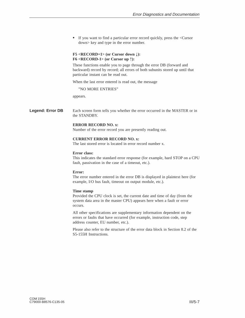
III/5-7COM 155HC79000-B8576-C135-05
If you want to find a particular error record quickly, press the <Cursordown> key and type in the error number.
F5 <RECORD+1> (or Cursor down ):F6 <RECORD-1> (or Cursor up ):
These functions enable you to page through the error DB (forward andbackward) record by record; all errors of both subunits stored up until thatparticular instant can be read out.
When the last error entered is read out, the message
”NO MORE ENTRIES”
appears.
Each screen form tells you whether the error occurred in the MASTER or inthe STANDBY.
ERROR RECORD NO. x:Number of the error record you are presently reading out.
CURRENT ERROR RECORD NO. x:The last stored error is located in error record number x.
Error class:This indicates the standard error response (for example, hard STOP on a CPUfault, passivation in the case of a timeout, etc.).
Error:The error number entered in the error DB is displayed in plaintext here (forexample, I/O bus fault, timeout on output module, etc.).
Time stampProvided the CPU clock is set, the current date and time of day (from thesystem data area in the master CPU) appears here when a fault or erroroccurs.
All other specifications are supplementary information dependent on theerrors or faults that have occurred (for example, instruction code, stepaddress counter, EU number, etc.).
Please also refer to the structure of the error data block in Section 8.2 of theS5-155H Instructions.
Legend: Error DB
Error Diagnostics and Documentation

III/5-8COM 155H
C79000-B8576-C135-05
5.3 Documenting with COM 155H
Press <F7> in the Main Menu to get into the ”System Handling” menu. The<F1> key takes you into the Directory menu. From this menu, you can printout an overview of your configuration in the form of a list. With <F4> youget the configuration from the programmable controller, with <F5> from thediskette.
Example:
I/O group ! I/O type ! Subunit ! Number
Digital inputs ! one-sided I/O ! A ! 2
Digital inputs ! one-sided I/O ! B ! 2
Digital inputs ! switched I/O ! ! 36
Digital inputs ! redundant I/O ! ! 6
Digital inputs ! 3-channel I/O ! ! 3
Digital outputs ! one-sided I/O ! A ! 4
Digital outputs ! one-sided I/O ! B ! 0
Digital outputs ! switched I/O ! ! 40
Digital outputs ! redundant I/O ! ! 13
Analog inputs ! one-sided I/O ! A ! 2
Analog inputs ! one-sided I/O ! B ! 0
Analog inputs ! switched I/O ! ! 14
Analog inputs ! redundant I/O ! ! 8
Analog inputs ! 3-channel I/O ! ! 6
Analog outputs ! one-sided I/O ! A ! 0
Analog outputs ! one-sided I/O ! B ! 8
Analog outputs ! switched I/O ! ! 8
Analog outputs ! redundant I/O ! ! 8
CP/IP interfaces ! one-sided I/O ! A ! 1
CP/IP interfaces ! one-sided I/O ! B ! 1
CP/IP interfaces ! switched I/O ! ! 9
Printing theConfigurationOverview
Error Diagnostics and Documentation

III/5-9COM 155HC79000-B8576-C135-05
Press <F4> in the ”System Handling” menu to get into the COM 155H PrintMenu. You can have your configuration printed out in tabular form from thismenu.
If the data is to be printed out from the programmable controller, diskette orEPROM flash memory card, it must first be loaded into the programmer’smemory. This is done from the System Handling menu, F3 <TRAN LOAD>.
A footer is printed out on each page.
COM 155H Print Menu COM 155H / PEC16
DI DQ AI AQ CP/IP TYPES ALL BACK
F6F5F4F3F2F1 F7 F8
Program file: E:@@@@@@ST.S5D
F1 DI :Print configured digital inputs
F2 DQ :Print configured digital outputs
F3 AI :Print configured analog inputs
F4 AQ :Print configured analog outputs
F5 CP/IP :Print configured interfaces
F6 TYPES :Print particular types
F7 ALL :Print the whole configuration
F8 BACK :Return to previous menu
Figure 5-6 Print Menu
You can execute the following functions using <F1> to <F7>:
F1 <DI>: Print out all DI types (digital inputs)
F2 <DQ>: Print out all DQ types (digital outputs)
F3 <AI>: Print out all AI types (analog inputs)
F4 <AQ>: Print out all AQ types (analog outputs)
Example: Table of DI Types (F1)
I/O byte ! Short symbol
! Type!
! Subunit!
I/O byte ! Short symbol
! Type!
! Subunit!
IB 0 ! ! 2 ! IB 1 ! ! 2 !
IB 126 ! ! L-DI ! IB 127 ! ! L-DI !
Printing theConfigurationDB/DX
Functions in thePrint Menu
Error Diagnostics and Documentation

III/5-10COM 155H
C79000-B8576-C135-05
F5 <CP/IP>: Print all CP and IP types (interface no.)
Example: Table of CP/IP Types (F5)
Interface number ! Type!
! Subunit!
Interface number ! Type!
! Subunit!
0 ! 24 ! A 10 ! 24 ! B
F6: Printout of individual types, printout of <SELECT> the configured L-DIs, L-DQs and R-DIs
(bit assignment) or printout of youroperating system parameter settings.
COM 155H Print Menu COM 155H / PEC16
Program file: B:@@@@@@ST.S5D
Types one-sided subunit A
Types one-sided subunit B
Types switched
Types redundant
Types 3-channel
L-DI, L-DQ, R-DI
OS configuration
DQ AQAI CP/IPDI
xxxx xxxx xxxx
x
xxxx
Figure 5-7 Print Menu (TYPES, F6)
Position the cursor to the desired field and press <RETURN> or <ESC>.What you have selected will be output to the printer.
Example: Types; redundant DI
DI type 3: Two-channel digital inputs ”redundant I/O”
DI byte ! Short symbol!
! Discrep.! time (sec)
! L-DQ! byte/bit
! L-DI! byte/bit
I 5.0 ! ! 0.05 ! 130.5 ! 6.2
I 5.1 ! ! 0.05 ! 130.5 ! 6.2
I 5.2 ! ! 0.05 ! 130.5 ! 6.2
Error Diagnostics and Documentation

III/5-11COM 155HC79000-B8576-C135-05
Example: L-DI, L-DQ, R-DI
Bit assignment digital outputs:
Bits -> ! 0 ! 1 ! 2 ! 3 ! 3 ! 5 ! 6 ! 7
DQ byte 130 ! ! ! ! ! !DI-LDQ ! !
Bit 5 of digital output byte 130 has been configured as a locating digitaloutput for a redundant digital input. The other bits are still unassigned.
If you mark the OS configuration field in the Print Menu with a cross(”check” it), you get a printout of the following:
1. The operating system parameters
2. The transfer data for standby activation and
3. The I/O areas of the expansion units.
F7 <ALL>: The entire configuration is printed out.
This function enables you to print out out all the data of your configuration:
1. The operating system parameters (see above) and
2. The entire I/O configuration.
Error Diagnostics and Documentation

III/5-12COM 155H
C79000-B8576-C135-05
Error Diagnostics and Documentation

Preface, Contents
CC 155H 1
Subrack 2
Power Supply Unit 3
Fan Subassembly 4
General Technical Data 5
C79000-B8576-C139-06
CC 155H
Instructions(CC 155H, Part IV)
SIMATIC S5

ii
#%$#$#')%#%#"&$#%")%"' "##$)#'#$
"$$$ "%$$!% $#$#"$$%)'"
$"""#'#"$$&"
!Danger
$#$$$#&" "#%")"#%#$$ " "$)"#%$ " " "%$#
"$$
!Warning
$#$$$#&" "#%")"#%#$$ " "$)"#%$ " " "%$#
"$$
!Caution
$#$$" "#%")" " "$)"#%$ " " "%$#"$$
Note
"'#)%"$$$$ "$%") "$$"$$ "%$$ "%$"$
"$%" "$$%$$
) #%'$#$'"$#!% $ % "##"
# "##'"%$"*$##$"%$$"%$#!% $
#)#$#"'$#$##$) "$##$"#
$$'
!Warning
#&$# $#))%#"$ $##"$$"$
$#" $)$'$&#" $#"$"%$%""#'& "&"")#
# "%$)%$""$)#)$#$"# "$#$"#$% #$""$)
"$$#"
""#$"$""#
" "$#%#"$"' %" ##)$"#$#%$'""$$""#$
"% $"$#$$""'"#
&$$$#$#%""$'$$"'"#$'"#"&$#$ "%$")'$%"$%"$'&"$$$#%""&'"%"))##")""$#%#%#!%$$#%#$#" "&$"'
Disclaimer of LiabilityCopyright Siemens AG 1994 All rights reserved
" "%$$"###"%#$#%$"$#$$##$ "$$'$%$( "##'"$$%$"$)"#'"#"$#%"$#"$) $$"$""#$"$%$$)"#""#"&
Siemens AGBereich Automatisierungs- und AntriebstechnikGeschaeftsgebiet Industrie AutomatisierungssystemePostfach 4848, D-90327 Nuernberg
Siemens AG 1994$#%$$
Siemens Aktiengesellschaft C79000-B8576-C139
Safety Guidelines
Qualified Personnel
Correct Usage
Trademarks
iiiCC 155HC79000-B8576-C139-06
Preface
This manual describes the hardware of the 155H central controller and thedifferences between the CC 155H and the S5-155H programmable controller.
The CC 155H differs from the S5-155H programmable controller mainly bythe fact that smaller redundant systems with only one rack and therefore verycompact can be constructed.
This manual describes all the steps necessary to install and operate theCC 155H. It supports you in learning the functions of the CC 155H quicklyand effectively.
The manual is intended for the following audience:
Installers
Startup specialists
Service and maintenance personnel
This manual contains the description of the 155H central controller whichwas valid at the time the manual went to print. We reserve the right todescribe any changes to the functionality of the CC 155H in a ProductInformation.
The following approvals exist for the CC 155H:
UL Recognition MarkUnderwriters Laboratories (UL) in accordance withStandard UL 508
CSA Certification MarkCanadian Standard Association (CSA) in accordance withStandard C 22.2 No. 142
The approvals apply if the appropriate labels are visible on all components.
Purpose of theManual
Audience
Validity of thisManual
Approvals

ivCC 155H
C79000-B8576-C139-06
Our products meet the requirements of EC Directive 89/336/EEC‘Electromagnetic Compatibility’.
In accordance with the Article 10 of the above-mentioned EC Directive, theEU declarations of conformity are held at the disposal of the competentauthorities at the address below:
Siemens AGAutomation GroupAUT E 148Postfach 1963D-92209 Amberg
This manual describes the hardware of the 155H central controller. You willrequire the following additional manuals for programming andcommissioning a CC 155H:
Manual Content Order Number
SIMATIC S5
S5-135U/155U
System Manual
Centralized and distributed configuration of a programmablecontroller
Installation guidelines
Central controllers and expansion units
CPUs, memory cards, memory submodules, interfacesubmodules
Interface modules
Digital input/output modules
Analog input/output modules
Monitoring modules
Connector assignments
6ES5 998-0SH21
SIMATIC S5
S5-155H
ProgrammableController
Programming Guide
Components of STEP 5 user programs
Basics of STEP 5 programming with examples
Operating statuses and program execution levels of theCPU 948R
Interrupt and error diagnosis
Special functions of the system program
Memory assignment and memory organization of theCPU 948R
PG interfaces and PG functions
6ES5 998-4SR21
To facilitate rapid access to special information, the manual contains thefollowing aids:
Given at the beginning of the manual is a full table of contents.
In the chapters, each page contains information in the left column whichsummarizes the contents of the section.
CE Mark
Other RelevantDocumentation
Structure of thisManual
Preface

vCC 155HC79000-B8576-C139-06
If you have any questions regarding the products described in this manualand cannot find an answer, please contact the Siemens representative in yourarea. You will find a list of addresses in catalogs, and in Compuserve (goautforum) .
If you have any questions or comments on this manual, please fill out theremarks form at the end of the manual and return it to the address shown onthe form. We would be grateful if you could also take the time to answer thequestions giving your personal opinion of the manual.
Siemens also offers a number of training courses to introduce you to theSIMATIC S5 automation system. Please contact your regional training centeror the central training center in Nuremberg, Germany for details:
Tel. (+49) (911) 895 3154.
You will find the latest updated information on SIMATIC products:
On the Internet under http://www.aut.siemens.de/
Via fax polling no. 08765-93 02 77 95 00
SIMATIC Customer Support offers help by means of up-to-date informationand downloads which may be useful to you when using SIMATIC products:
On the Internet under http://www.aut.siemens.de/simatic-cs
Via the SIMATIC Customer Support Mailbox under the number+49 (911) 895-7100
Use a V.34 (28.8 Kbps) modem to access the mailbox and set itsparameters as follows: 8, N, 1, ANSI, or dial in using ISDN (x.75,64 Kbits).
You can reach SIMATIC Customer Support by phone using the number+49 (911) 895-7000 and by fax using the number +49 (911) 895-7002. Youcan also send your queries by E-Mail on the Internet or by mail to the abovemailbox.
AdditionalAssistance
The LatestInformation
Preface

viCC 155H
C79000-B8576-C139-06
Preface

viiCC 155HC79000-B8576-C139-06
Contents - Part IV
1 155H Central Controller 1-1. . . . . . . . . . . . . . . . . . . . . . . . . . . . . . . . . . . . . . . . . . . . . . . . .
1.1 Overview of the CC 155H 1-2. . . . . . . . . . . . . . . . . . . . . . . . . . . . . . . . . . . . . . . .
1.2 Device Configurations with the CC 155H 1-5. . . . . . . . . . . . . . . . . . . . . . . . . . .
1.3 Installing the CC 155H 1-7. . . . . . . . . . . . . . . . . . . . . . . . . . . . . . . . . . . . . . . . . . .
2 Subrack 2-1. . . . . . . . . . . . . . . . . . . . . . . . . . . . . . . . . . . . . . . . . . . . . . . . . . . . . . . . . . . . . . . .
2.1 Subrack 2-2. . . . . . . . . . . . . . . . . . . . . . . . . . . . . . . . . . . . . . . . . . . . . . . . . . . . . . . .
2.2 Configuration with SIMATIC S5 Modules 2-3. . . . . . . . . . . . . . . . . . . . . . . . . . .
3 Power Supply Unit 3-1. . . . . . . . . . . . . . . . . . . . . . . . . . . . . . . . . . . . . . . . . . . . . . . . . . . . . .
3.1 Characteristics 3-2. . . . . . . . . . . . . . . . . . . . . . . . . . . . . . . . . . . . . . . . . . . . . . . . . .
3.2 Inputs and Outputs 3-4. . . . . . . . . . . . . . . . . . . . . . . . . . . . . . . . . . . . . . . . . . . . . .
3.3 Indicators and Controls 3-6. . . . . . . . . . . . . . . . . . . . . . . . . . . . . . . . . . . . . . . . . . .
3.4 Configuration Switches 3-8. . . . . . . . . . . . . . . . . . . . . . . . . . . . . . . . . . . . . . . . . . .
3.5 Fault Display via LEDs 3-10. . . . . . . . . . . . . . . . . . . . . . . . . . . . . . . . . . . . . . . . . . .
3.6 Installing and Removing a Power Supply Unit 3-11. . . . . . . . . . . . . . . . . . . . . . .
3.7 Replacing a Fuse 3-13. . . . . . . . . . . . . . . . . . . . . . . . . . . . . . . . . . . . . . . . . . . . . . . .
3.8 Wiring the Power Supply Unit 3-14. . . . . . . . . . . . . . . . . . . . . . . . . . . . . . . . . . . . .
3.9 Backup Battery (Option) 3-16. . . . . . . . . . . . . . . . . . . . . . . . . . . . . . . . . . . . . . . . . .
3.10 Replacing the Backup Battery 3-19. . . . . . . . . . . . . . . . . . . . . . . . . . . . . . . . . . . . .
3.11 Technical Specifications 3-20. . . . . . . . . . . . . . . . . . . . . . . . . . . . . . . . . . . . . . . . . .
4 Fan Subassembly 4-1. . . . . . . . . . . . . . . . . . . . . . . . . . . . . . . . . . . . . . . . . . . . . . . . . . . . . .
4.1 Characteristics 4-2. . . . . . . . . . . . . . . . . . . . . . . . . . . . . . . . . . . . . . . . . . . . . . . . . .
4.2 Fan Monitoring in the Fan Subassembly 4-5. . . . . . . . . . . . . . . . . . . . . . . . . . . .
4.3 Changing the Air Flow in the Fan Subassembly 4-7. . . . . . . . . . . . . . . . . . . . . .
4.4 Installing the Fan Subassembly 4-10. . . . . . . . . . . . . . . . . . . . . . . . . . . . . . . . . . .
4.5 Wiring the Fan Subassembly 4-11. . . . . . . . . . . . . . . . . . . . . . . . . . . . . . . . . . . . . .
4.6 Cable Routing When Using the Fan Subassembly 4-12. . . . . . . . . . . . . . . . . . .
4.7 Replacing the Fuse in the Fan Subassembly 4-13. . . . . . . . . . . . . . . . . . . . . . . .
4.8 Replacing Fans in the Fan Subassemblies during Operation 4-14. . . . . . . . . .
4.9 Replacing the Monitoring PCB of the Fan Subassembly 4-16. . . . . . . . . . . . . .

viiiCC 155H
C79000-B8576-C139-06
5 General Technica l Data 5-1. . . . . . . . . . . . . . . . . . . . . . . . . . . . . . . . . . . . . . . . . . . . . . . . .
5.1 Notes on the CE Mark 5-2. . . . . . . . . . . . . . . . . . . . . . . . . . . . . . . . . . . . . . . . . . .
5.2 Technical Specifications 5-3. . . . . . . . . . . . . . . . . . . . . . . . . . . . . . . . . . . . . . . . . .
Contents - Part IV

IV/1-1CC 155HC79000-B8576-C139-06
155H Central Controller
Section Description Page
1.1 Overview of the CC 155H IV/1-2
1.2 Device Configurations with the CC 155H IV/1-5
1.3 Installing the CC 155H IV/1-7
Name Order Number
CC 155H 6ES5 188-3UH31
ChapterOverview
Order Numbers
1

IV/1-2CC 155H
C79000-B8576-C139-06
1.1 Overview of the CC 155H
This manual shows the special features of the CC 155H and is intended forusers who are familiar with the S5-155U and S5-155H programmablecontrollers.
The CC 155H is a fault-tolerant programmable controller for machine andplant control. It is similar in function to the S5-155H programmablecontroller.
The CC 155H is an event-synchronized master-standby system like theS5-155H with a 1-out-of-1 structure. In contrast to the S5-155H, bothsubunits (master and standby) in the CC 155H can be mounted in one singlesubrack. This allows you to structure a redundant programmable controlsystem with a minimum of space.
!Warning
The CC 155H programmable controller (H system) is, despite its highfault-tolerance and its isolated structure, not a fail-safe system.
It must never be used in plants or installations in which a programmablecontroller fault (e.g. an improbable total failure of both subunits) could causedangerous operating statuses and therefore result in danger to persons,machines or the environment.
Safety-related automation tasks of this nature require either the use of asafety-oriented programmable controller (e.g. an S5-115F system which wasprototype-tested by the TÜV (German Technical Inspectorate)) or theCC 155H must be equipped with suitable interlocks or protective systemswhich prohibit the occurrence of dangerous operating statuses.
The CC 155H (see Figure 1-1) comprises the following components:
Subrack
Power supply units
Fan subassembly
Introduction
Components ofthe CC 155H
155H Central Controller

IV/1-3CC 155HC79000-B8576-C139-06
3 11 19 27 35 43 51 67 75 83 91 99 107 115 123 131 139 147 155 16359
Subunit 1 Subunit 2
1AT
1
2
1 = Subrack
3 = Power supply unit (PS)
2 = Fan subassembly
3
Jumpersettings:
Lower jumper inserted: CC(state on leavingfactory)
Upper jumperinserted: EU
Figure 1-1 CC 155H, Front View
You can insert the following modules in the free slots in each subunit:
CPU 948R
Interface modules (IMs)
Communications processors (CPs)
I/O modules (DI, DO, AI, AO)
155H Central Controller

IV/1-4CC 155H
C79000-B8576-C139-06
The CC 155H contains two independent subunits in one subrack andcombines the functions of two independent central controllers in one subrack.Each subunit requires its own power supply unit.
You will find more details about the rack in Chapter 2.
The power supply unit supplies the other modules in each subunit with theiroperating voltages via the backplane bus of the subrack.
You will find more details about the power supply module in Chapter 3.
The fan subassembly is used to ventilate the CC 155H. It is an obligatory partof the system and must always be installed immediately below the subrack ofthe CC 155H.
You will find more details about the fan subassembly in Chapter 4.
The following operating modes can be set for each subunit of the CC 155Hindependently:
Central controller mode (CC)
Expansion unit mode (EU)
The modes are set using jumpers. These jumpers are accessible from thefront in the subrack (see Figure 1-1).
The state on shipping from the factory is central controller mode (lowerjumpers inserted).
Subrack
Power Supply Unit
Fan Subassembly
Jumper Settings
155H Central Controller

IV/1-5CC 155HC79000-B8576-C139-06
1.2 Device Configurations with the CC 155H
This section shows how you can configure various different programmablecontroller structures with the CC 155H.
You can connect expansion units to the central controller CC 155H. You usethe interface modules IM 304 and IM 314R to link them up.
Figure 1-2 shows an example of how you can expand the CC 155H with anEU 185U.
PS PSCPU948R
IM324R
IM304
CPU948R
IM314R
IM314R
CC 155H centralcontroller
EU 185U
IM304
IM304
Power supply
Figure 1-2 CC 155H with EU 185U
Overview
ConnectingExpansion Units
CC 155H withEU 185U
155H Central Controller

IV/1-6CC 155H
C79000-B8576-C139-06
You can also use the CC 155H as a “shared expansion unit”. This means youcan connect up to six or seven I/O modules in the “switched I/O” mode to aCC 155H (see Figure 1-3).
This has the advantage that two central controllers with a switched I/O can becompletely contained in one cabinet.
PS PSCPU948R
IM324R
IM304
CPU948R
IM314R
IM314R
CC 155H as centralcontroller
IM304
IM304
PS PSCPU948R
IM324R
IM304
CPU948R
IM304
IM304
IM314R
IM314R
PSPS
CC 155H as sharedexpansion unit
CC 155H as centralcontroller
Figure 1-3 CC 155H as a “Shared” Expansion Unit
CC 155H as a“Shared”Expansion Unit
155H Central Controller

IV/1-7CC 155HC79000-B8576-C139-06
1.3 Installing the CC 155H
The CC 155H is suitable for the following types of installation:
Cabinet installation
Mounting on racks
Figures 1-4, 1-5 and 1-6 show the most important dimensions for theinstallation of the CC 155H and its installation position in a 19-inch cabinet.
1AT
19-inch reference level
440
482.6465
260.9
0
5
44
127.5138.4
221.8
265.9
Additional CC 155H
482.5
36
0
93109.5
310.0
Figure 1-4 Mounting Dimensions of a CC 155H
Mounting aCC 155H
155H Central Controller

IV/1-8CC 155H
C79000-B8576-C139-06
approx. 40 mm
19-inch referencelevel Position of cabinet
uprights (TELEPERM XPcabinet)
Subrack
Fan sub-assem-bly
225
max. 230 mm
Centralgroundingpoint
Figure 1-5 Installation Position of the CC 155H (Side View)
The CC 155H is suitable for “one-man installation”.
For connection and maintenance purposes, the CC 155H only needs to beaccessible from the front.
Use M6 screws to fix the CC 155H.
Use self-tapping M6 screws to fix the CC 155H in a TELEPERM XP cabinet.
155H Central Controller

IV/1-9CC 155HC79000-B8576-C139-06
Proceed as follows to install the CC 155H:
1. First fix the fan subassembly. It is screwed directly to the cabinet or rackuprights by its fixing surfaces from behind.
You can only mount the fan subassembly in certain intervals within the19-inch reference level owing to the arrangement of the cutouts. If you fixthe rack first, the fan subassembly may not be able to be arrangedimmediately below it.
2. Fix the CC 155H subrack immediately above the fan subassembly. Itshould be screwed from behind directly to the cabinet or rack uprightsusing its mounting brackets.
To make installation easier, you can rest the subrack on the fansubassembly which is already fixed.
3. Connect the central grounding point of the CC 155H to chassis ground.An M5 screw is provided for this purpose at the bottom rear left of thesubrack (see Figure 1-5).
The minimum cross section of the chassis ground cable should be:16 mm2.
Note
Ensure that there is always a low-impedance connection to chassis ground.You achieve this by using a short a cable as possible, with low resistance anda large-area good quality contact.
Note
If you do not mount the subrack immediately above the fan subassembly asshown in Figures 1-4 and 1-5, there is no guarantee that the CC 155H will beadequately ventilated.
155H Central Controller

IV/1-10CC 155H
C79000-B8576-C139-06
Figure 1-6 shows an example of the mounting position of the CC 155H in aTELEPERM XP cabinet.
Cabinet uprights (TELEPERM XP cabinet)
Front
RearM6 fixingscrews
M6 fixingscrews
Subrack
Figure 1-6 Mounting Position of the CC 155H (Top View)
155H Central Controller

IV/2-1CC 155HC79000-B8576-C139-06
Subrack
Section Description Page
2.1 Subrack IV/2-2
2.2 Configuration with SIMATIC S5 Modules IV/2-3
Name Order Number
CC 155H subrack 6ES5 188-3UH51
ChapterOverview
Order Numbers
2

IV/2-2CC 155H
C79000-B8576-C139-06
2.1 Subrack
The subrack for the CC 155H is divided into two electrically separated areas.The first ten slots (BEP 3 to 75) are assigned to subunit 1, the remainingeleven slots (BEP 83 to 163) are assigned to subunit 2.
The extreme left slot in each subunit is intended for the power supply unit.
The CPU is always inserted immediately next to the power supply unit.Multiprocessor operation is not possible in the CC 155H.
In addition to the CPU, there is a slot for connecting up via the interfacemodule pair IM 304/324R.
Unused slots should be covered with dummy front plates. This directs thecooling air in the subrack and prevents the inside of the slot being touched.
The dummy front plates should be ordered separately. Their order numbersare as follows:
Dummy front plate width 1 slot: 6XF2008-6KB00
Dummy front plate width 2 slots: 6XF2016-6KB00
3 11 19 27 35 43 51 67 75 83 91 99 107 115 123 131 139 147 155 16359
Subunit 1 Subunit 2
Locking bar withlabeling strip
Figure 2-1 CC 155H Subrack
Characteristics ofthe Subrack
Subrack

IV/2-3CC 155HC79000-B8576-C139-06
2.2 Configuration with SIMATIC S5 Modules
The CC 155H can be used in the following ways:
CC 155H as a central controller
CC 155H as a shared, switched expansion unit
CC 155H split as both CC and EU
This means the configuration possibilities are different.
Table 2-1 shows the valid slot assignments for the CC 155H usingSIMATIC S5 modules when the CC 155H is operating as a central controller(CC). The following rules apply to slot assignments:
The power supply unit (PS) always occupies both the extreme left slots ineach subunit.
The CPU is always inserted immediately to the right of the power supplyunit.
The IM 304 or IM 324R module for linking the two subunits is insertedimmediately to the right of the CPU.
The remaining slots are “standard slots” for operating I/O, FM and CPmodules.
Only modules which have an 8-bit wide data bus connection can beoperated in the two extreme right slots of each subunit.
Overview
Configuration as aCentral Controller
Subrack

IV/2-4CC 155H
C79000-B8576-C139-06
Table 2-1 Slot Assignments as a Central Controller
Slot No.:
Module Type
3 11 19 27 35 43 51 59 67 75 83 91 99 107 115 123 131 139 147 155 163
PS
CPU 948 R
IM 304/IM 324R
IM 304 1) 2) 2) 1) 2) 2)
IM 308
CP 1430
CP 5430
CP 581
DI, DO, AI,AO
IP 2xx
1) 16-bit access is also permitted to these slots; there are no restrictions to the use of the IM 304.2) Only 8-bit access is permitted to these slots. If you connect the switched I/O via the IM 304 here, the CPU 948R
recognizes in its self-tests that the upper eight data bits cannot be read back and enters this as message no. 40 in theerror data block. This message can be ignored. If the message disturbs you, you can switch off the respective test stepby entering the following instruction sequence in the startup OBs (OB20, OB21, OB22):
Segment 1Name: seq-absc
:SU RS 137.8:L DH 000E CFF3:LIR 1:L KH 0100:OW:L DH 000E CFF3:TIR 3......:BE
For operation as a central controller, both “lower” jumpers in the subrackmust be inserted (see Figure 1-1).
Jumper Settingsfor CentralController Mode
Subrack

IV/2-5CC 155HC79000-B8576-C139-06
Table 2-2 shows the valid slot assignments allowed for the CC 155H usingSIMATIC S5 modules when the CC 155H is operating as a shared expansionunit. The following rules apply to slot assignments:
The power supply unit (PS) always occupies the two extreme left slots ineach subunit.
An IM 314R module pair is inserted in the two extreme right slots in eachsubunit.
The remaining slots are “standard slots” for operating I/O, FM and CPmodules.
Table 2-2 Slot Assignments as a Shared Expansion Unit
Slot No.:
Module Type
3 11 19 27 35 43 51 59 67 75 83 91 99 107 115 123 131 139 147 155 163
PS
IM 314 R
IM 308/IM 308B/IM 308C
CP xxx
DI, DO, AI,AO
IP 2xx
For operation as a shared expansion unit, both “upper” jumpers in thesubrack must be inserted (see Figure 1-1).
You can operate one subunit in the subrack as a central controller and theother as an expansion unit. To do this, the “lower“ jumper in the subunit youwant to run as a CC must be inserted, in the other subunit the “upper” jumpermust be inserted (see Figure 1-1).
Refer to Tables 2-1 and 2-2 for the configuration possibilities for bothsubunits.
The CC 155H is provided with two labeling strips to mark the slots:
Labeling strip for central controller configuration (when shipped,mounted on the locking bar of the subrack)
Labeling strip for configuration as a shared expansion unit (suppliedloose)
For configuration as one CC and one EU, you can divide the strips in half inthe middle and use them for the respective half of the subrack.
Configuration as aShared ExpansionUnit
Jumper Settingsas a SharedExpansion Unit
Configuration forSplit CC/EU
Labeling Strips
Subrack

IV/2-6CC 155H
C79000-B8576-C139-06
Subrack
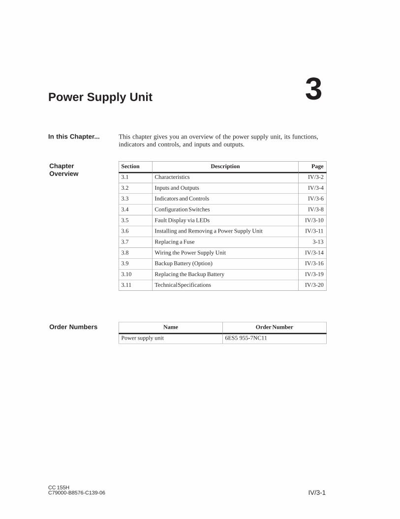
IV/3-1CC 155HC79000-B8576-C139-06
Power Supply Unit
This chapter gives you an overview of the power supply unit, its functions,indicators and controls, and inputs and outputs.
Section Description Page
3.1 Characteristics IV/3-2
3.2 Inputs and Outputs IV/3-4
3.3 Indicators and Controls IV/3-6
3.4 Configuration Switches IV/3-8
3.5 Fault Display via LEDs IV/3-10
3.6 Installing and Removing a Power Supply Unit IV/3-11
3.7 Replacing a Fuse 3-13
3.8 Wiring the Power Supply Unit IV/3-14
3.9 Backup Battery (Option) IV/3-16
3.10 Replacing the Backup Battery IV/3-19
3.11 Technical Specifications IV/3-20
Name Order Number
Power supply unit 6ES5 955-7NC11
In this Chapter...
ChapterOverview
Order Numbers
3

IV/3-2CC 155H
C79000-B8576-C139-06
3.1 Characteristics
The power supply unit supplies the other modules in the subrack with theiroperating voltages via the backplane bus. It does not provide load voltagesfor the signal modules.
The most important characteristics of the power supply unit are:
Nominal input voltage:
– 24 V DC
Output voltages:
– 5 V DC / 14 A
– 24 V DC / 1 A
Short-circuit proof
Ability to withstand overload currents
Reverse voltage protection
Protection against incorrect insertion
Overvoltage protection for 5-V output
Control and monitoring signals
Display LEDs
Redundant backup battery with monitoring (option)
Both output voltages (5 V DC and 24 V DC) share a common ground
Primary/secondary galvanic isolation (see following note)
Introduction
Characteristics
Power Supply Unit

IV/3-3CC 155HC79000-B8576-C139-06
Note
The power supply unit 6ES5 955-7NC11 has no safe isolation between inputand output. The 24 V DC supply to this power supply unit must be generatedwith safe isolation.
Note
The power supply unit 6ES5 955-7NC11 is only intended for operation in theCC 155H.
Power Supply Unit

IV/3-4CC 155H
C79000-B8576-C139-06
3.2 Inputs and Outputs
The inputs and outputs of the power supply unit are arranged on the frontplate. Figure 3-1 shows the position of the inputs and outputs on the frontplate.
14
13
12 +
11 –
10
9
8
7
6
5
4 +
3 –
2 +
1 –
!$
!$
"
#
Control inputSupply for control input
Load voltage monitoring
Fault indicator signal forload voltage monitoring
Fault indicator signal forbattery monitoringEnable voltage for I/Omodules
Voltage supply
Cable grip
Locking bolt
Current test socketsG
IK
L
M
N
O
P
Latch for battery compartment
Lever
Battery compartmentA
Figure 3-1 Front View of the Power Supply Unit
Overview
Power Supply Unit

IV/3-5CC 155HC79000-B8576-C139-06
Table 3-1 gives an overview of the labeling and purpose of the inputs andoutputs.
Table 3-1 Meaning of the Inputs and Outputs
ID Label Element Purpose
G 3V 14A
INTERNAL
2 test sockets Current measurement sockets for testpurposes only; no continuous operation,linearity range 0 V / 0 A to 3 V / 14 A
I EN Screw terminal 14 Control input for power supply unit(Enable Power Supply):
V 2.72 V = OFFV 3.27 V = ON
K UH Screw terminal 13 5 V auxiliary voltage to supply controlinput EN
L DC 24 V INPUT V MON.
Screw terminals 11and 12
Load voltage input (Voltage Monitor),monitors 24 V load voltage for > 15.2 V
M DC 24 V 0,2A max. ALARM
Screw terminals 8,9, 10
Relay fault indicator signal for loadvoltage monitoring:
ALARM8 – 10 closed Rest position of relay: load voltage
failed or BASPA signal from CPUactive or power supply unit has nocurrent
8 – 9 closed Work position of relay: load voltage invalid range
N DC 24 V 0,2A max. BATTERY
Screw terminals 5,6, 7
Relay fault indicator signal for batterymonitoring:
BATTERY5 – 7 closed Rest position of relay: at least one
battery monitoring operating or thebattery voltage on the bus is too low
5 – 6 closed Work position of relay: no batterymonitoring operating
O DC 24 V 1A int. OUTPUT
Screw terminals3 and 4
24 V DC for supply enable voltage forI/O modules
P DC 24 V 7A DC LINE
Screw terminals1 and 2
Input for 24 V DC supply voltage
Power Supply Unit

IV/3-6CC 155H
C79000-B8576-C139-06
3.3 Indicators and Controls
The indicators and controls of the power supply unit are arranged on the frontplate. Figure 3-2 shows the position of the indicators and controls on thefront plate.
14
13
12 +
11 –
10
9
8
7
6
5
4 +
3 –
2 +
1 –
!$
!$
"
#
Battery compartment
Fault display left batteryFault display right battery
Acknowledgement switch
24 V DC LED5 V DC LED
Standby switch
Cable grip
Locking bolt
A
BCD
EF
H
Latch for battery compartment
Lever
Figure 3-2 Front View of the Power Supply Unit
Overview
Power Supply Unit

IV/3-7CC 155HC79000-B8576-C139-06
Table 3-2 gives an overview of the labeling and purpose of the indicators andcontrols.
Table 3-2 Meaning of the Indicators and Controls
ID Label Element Purpose
A – Batterycompartment
1 or 2 backup batteries behind a cover
BFAULT BATTERY
Yellow LEDright
Fault display for the right backup battery
CBATTERY
Yellow LED left Fault display for the left backup battery
D RESET BATTERY
Pushbutton Acknowledge a battery failure once thebattery is replaced
E DC 24V INTERNAL
Green LED Lights up when the output voltage is in thevalid range
F DC 5VINTERNAL
Green LED Lights up when the output voltage is in thevaid range
H PWR Switch Standby on/off witch (no power on/off switch)
Position : both output voltages and theenable voltage for I/O modules are 0.
Position : both output voltages and theenable voltage for I/O modules exact.
Power Supply Unit

IV/3-8CC 155H
C79000-B8576-C139-06
3.4 Configuration Switches
The configuration switches are accessible from the right side of the powersupply unit. They can only be switched when the power supply unit isdisconnected from the mains supply and removed.
Using the configuration switches the behavior of some of the monitoringfunctions on the power supply unit can be set. The configuration switches arein the form of DIL switches.
Figure 3-3 shows the configuration switches.
5 61 2 3 4
Front plate
Right side wall
Configuration switch
0
1
0
1
Switch 6unused
Figure 3-3 Configuration Switches
The meaning of the switch positions of the configuration switches is listed inTable 3-3. The factory default setting is shown in bold typeface in the table.
Where?
Function of theConfigurationSwitches
Power Supply Unit
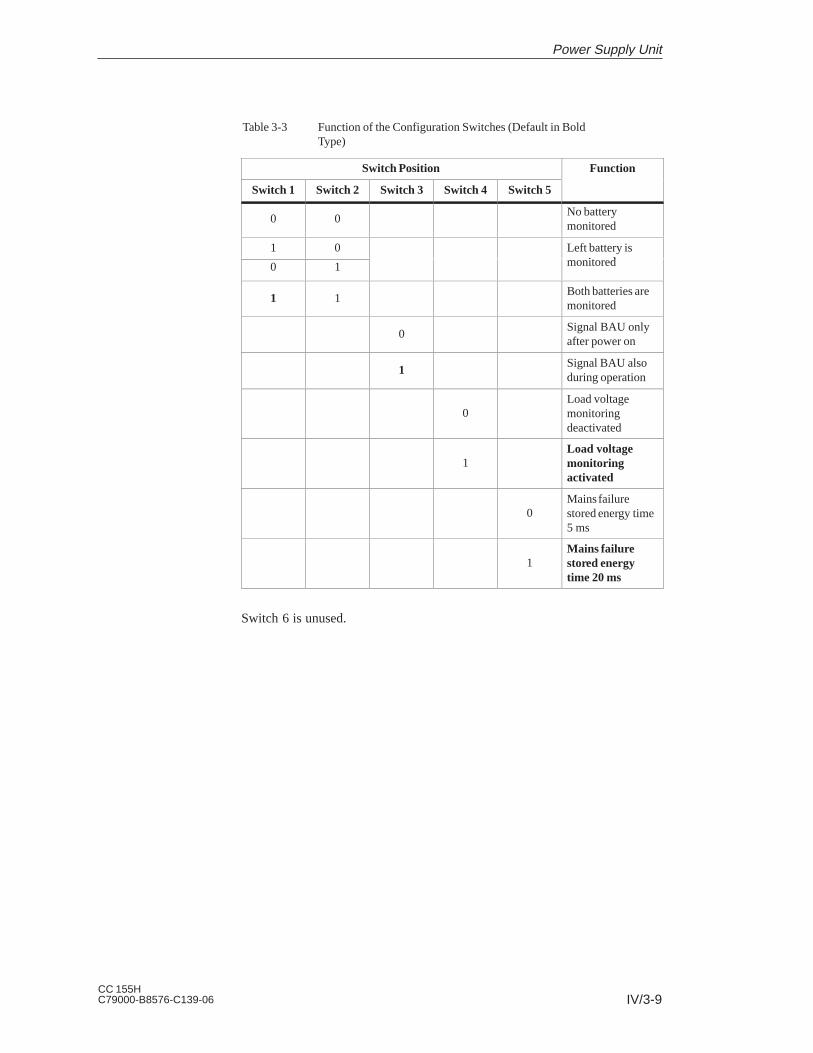
IV/3-9CC 155HC79000-B8576-C139-06
Table 3-3 Function of the Configuration Switches (Default in BoldType)
Switch Position Function
Switch 1 Switch 2 Switch 3 Switch 4 Switch 5
0 0No batterymonitored
1 0 Left battery isi d0 1 monitored
1 1Both batteries aremonitored
0Signal BAU onlyafter power on
1Signal BAU alsoduring operation
0Load voltagemonitoringdeactivated
1Load voltagemonitoringactivated
0Mains failurestored energy time5 ms
1Mains failurestored energytime 20 ms
Switch 6 is unused.
Power Supply Unit

IV/3-10CC 155H
C79000-B8576-C139-06
3.5 Fault Display via LEDs
Faults in the power supply unit and the backup battery(ies) are indicated onthe front plate of the power supply unit.
If all monitoring functions are activated (see Section 3.4, ConfigurationSwitches), the following fault indicators may appear:
LED Cause Remedy
Left LED BATTERY FAULTlights up
The left battery is missing orhas failed
Insert new battery (seeSection 3.10)
Acknowledge by pressingRESET switch
Right LED BATTERY FAULTlights up
The right battery is missing orhas failed
Insert new battery (seeSection 3.10)
Acknowledge by pressingRESET switch
Green LEDs DC 5Vand DC 24V dark
The Enable jumper EN–UHhas come loose
Check the EN–UH jumper
P5V overloaded (4.75 V) Remove overload
Retentive power off byovervoltage at output of P5V
Switch supply voltage off andon again (if this does notcorrect the fault, there is aninternal fault)
Fuse blown following reversalof supply voltage
Remove power supply unitand replace fuse (see Sections3.6 and 3.7)
Internal defect of the powersupply unit
Replace the power supply unit
Green LED DC 24Vd k
P24V overloaded (19.56 V) Remove overloaddark
External input of voltage29.6 V at output of P24V
Remove faulty input
Internal defect of the powersupply unit
Replace the power supply unit
Where are FaultsIndicated?
How are FaultsIndicated?
Power Supply Unit

IV/3-11CC 155HC79000-B8576-C139-06
3.6 Installing and Removing a Power Supply Unit
You install the power supply unit as follows:
1. Loosen the upper locking bar of the subrack and check whether thelocking bolt of the power supply unit is in the correct position: the slitshould be in a horizontal position.
2. Push the power supply unit into the guide rails of the subrack at slots 3and 11, and 83 and 91.
3. Push the power supply unit into the subrack until the lever is in ahorizontal position.
Caution: Do not apply pressure to the standby switch!
4. Lock the power supply unit by turning the locking bolt with a suitablescrewdriver by 90: the slit should be in a vertical position (seeFigure 3-4).
5. Fasten the upper locking bar of the subrack.
You must remove the power supply unit if you:
Change the setting of the configuration switch
Send the power supply unit to be repaired
Replace the fuse in the power supply unit (e.g. after accidental reversal of the input voltage)
You remove the power supply unit as follows:
1. Switch the standby switch to the position .
2. Disconnect the power supply unit from the mains.
3. Ensure that the other connections on the front terminals of the powersupply unit are de-energized.
4. Disconnect any cables from the front plate terminals and release the strainrelief cable grip.
5. Loosen the upper locking bar of the subrack.
6. Undo the locking bolt of the power supply unit by turning it with asuitable screwdriver by 90: the slit should be in a horizontal position(see Figure 3-4).
7. Press down the lever.
8. Pull the power supply unit out of the subrack.
Installing a PowerSupply Unit
When Should YouRemove the PowerSupply Unit?
How You Removethe Power SupplyUnit
Power Supply Unit

IV/3-12CC 155H
C79000-B8576-C139-06
4 +
3 –
2 +
1 –
Locking bolt
Lever
Slit vertical: modulelocked
Figure 3-4 Front View of the Power Supply Unit, Locking Mechanism
Power Supply Unit

IV/3-13CC 155HC79000-B8576-C139-06
3.7 Replacing a Fuse
You must change the fuse in the power supply unit if you, for example,reverse the input voltage polarity.
To change the fuse in the power supply unit, proceed as follows:
1. Remove the power supply unit (see Section 3.6).
2. The fuse is accessible from below. It is located on the power supply unitPCB near the lever (see Figure 3-5).
Lever out the blown fuse from the fuse carrier using a pointed object (forexample, screwdriver).
3. Press the new fuse into the fuse carrier.
Use only the following widely available fuse for the power supply unit:
Fuse type: 19341, 10 A / 250 V medium time-lag, 6.3 32mm (UL/CSA)
Fuse carrier
Lever
Components
Fuse
Figure 3-5 Power Supply Unit, View from Below
When Should YouChange the Fuse?
How Do YouChange the Fuse?
Which Fuse DoYou Use?
Power Supply Unit

IV/3-14CC 155H
C79000-B8576-C139-06
3.8 Wiring the Power Supply Unit
Table 3-4 shows what you should note when wiring the power supply unit.
Table 3-4 Wiring Rules
Rules for... Power Supply Unit
Connectable cable cross sections
without wire end ferrule
with wire end ferrule
0.2 to 2.5 mm2
0.2 to 2.5 mm2
For supply lines, a minimum of 1.5 mm2
Number of cables per connection 1 or combination of cables to 2.5 mm2
(sum) in a shared wire end ferrule
Maximum diameter of cable insulation ∅ 3.8 mm
Stripped length of cables 11 mm
Wire end ferrules acc. to DIN 46228
without insulating collar
with insulating collar
Form A, 10 to 12 mm long
Form E, to 12 mm long
Blade width of screwdriver 3.5 mm (cylindrical design)
Tightening torque for turning cables 0.5 to 0.8 Nm
The following applies to the assignment of the cables to the power supplyunit connections:
Table 3-5 Connection Assignments
Connection Cable Routing
Mains connection DC LINE Connect L+ to terminal 2
Connect L– to terminal 1
Load voltage monitoring V MON. Input 24-V DC load voltage.
Note polarity
Control input ENABLE PS Insert jumper from EN to UH or feedvoltage 3.6 V with respect to theoutput chassis ground to EN
Relay terminals (suitable up to 24 V DC/0.2 A)
Connect signaling circuits for battery andload voltage monitoring
DC 24 V OUTPUT Connect 24-V DC enable voltage for I/Omodules
Use shielded cables for the connections EN, UH and V MON. and contact thecable shields to the fan subassembly with the aid of the shielding clampssupplied.
Rules for Wiring
Wiring
Power Supply Unit

IV/3-15CC 155HC79000-B8576-C139-06
Below the connection terminals is a strain relief cable grip. Feed theconnecting cable for the power supply unit through this cable grip and tightenthe screws of the cable grip when you have finished wiring up.
4 +
3 –
2 +
1 –
Cable grip
Figure 3-6 Front View of the Power Supply Unit, Cable Grip
Cable Grip
Power Supply Unit

IV/3-16CC 155H
C79000-B8576-C139-06
3.9 Backup Battery (Option)
The power supply unit has a battery compartment to hold one or two backupbatteries.
If you use one or two backup batteries, the set parameters and the content ofthe RAM are backed up (stored) when the supply voltage fails via thebackplane bus in the CPU and in programmable modules, as long as thebattery voltage lies within the tolerance.
The backup battery also allows a warm restart of the CPU following POWERON.
The battery voltage is monitored by the power supply unit.
The power supply unit can be operated as follows:
without a backup battery
with only one backup battery(if you operate the power supply unit with only one backup battery, thismust be placed on the left in the battery compartment)
with two backup batteries (redundant backup)
The monitoring of the backup batteries can be switched on and off for eachbattery individually via a configuration switch. When shipped, monitoring ofboth batteries is switched on. When a battery fails, the corresponding LEDindicates the failure. The messages remain visible until the battery isreplaced and the acknowledgement switch is pressed.
When operating with two batteries, the monitoring function ensures that onebattery is fully discharged first before switching over to the reserve battery.The choice of backup and reserve battery following commissioning for thefirst time (or when both batteries are replaced at the same time) can berandom. Once the assignment has been made, this is stored even followingPOWER OFF.
Lithium batteries of the type AA are used as the backup batteries. These havethe following characteristics:
Nominal voltage: 3.6 V
Nominal capacity: 1.9 Ah
Only Siemens-approved batteries should be used.
Order number of the backup battery: 6ES7971-0BA00.
Introduction
Function of theBackupBattery/Batteries
Modes
Battery Type
Power Supply Unit

IV/3-17CC 155HC79000-B8576-C139-06
To insert the backup battery/batteries, proceed as follows:
1. First, discharge any static charge by touching a grounded metal part of theCC 155H.
2. Open the cover of the battery compartment.
3. Insert the backup battery/batteries in the battery compartment.
Ensure correct polarity of the battery/batteries. If you are only using onebackup battery, you must place it on the left in the compartment.
4. Switch on battery monitoring with the configuration switch (seepage IV/3-8).
Lithium batteries (lithium/thionyl chloride) are used as backup batteries forthe CC 155H. In lithium batteries of this technology, a passivation layer candevelop after storage for a very long time, and the immediate functionalcapability of the battery may not be certain. This may result in an errormessage when the power supply unit is switched on.
The power supply unit of the CC 155H is capable of reducing the passivationlayer of the lithium battery with a defined load on the battery. This processmay take some minutes. When the passivation layer has been reduced and thelithium battery has reached its rated voltage, the error message of the powersupply unit can be acknowledged with the RESET switch.
Since the storage time of the lithium battery is not usually known, werecommend the following procedure:
Insert the backup battery/batteries in the battery compartment.
Acknowledge any battery error message of the power supply unit with theRESET switch.
If the battery error cannot be cleared, try again after a few minutes.
If the battery error still cannot be cleared, remove the battery/batteriesand short-circuit it/them for one to three seconds maximum.
Reinsert the battery/batteries and try to acknowledge with the RESETswitch again.
If the battery error message goes off, the battery/batteries is/areoperational.
If the battery error message does not go off, the battery/batteries is/aredischarged.
The maximum backup time depends on the load on the backup battery. Witha battery capacity of 63% of the nominal capacity, the following valuesresult:
Imax 200 A backup time of approx. 250 days
Imax 4mA backup time of approx. 12.5 days
The maximum backup current is 4 mA.
Inserting theBackupBattery(ies)
Reducing thePassivation Layer
Backup Times
Power Supply Unit

IV/3-18CC 155H
C79000-B8576-C139-06
Backup batteries can be stored for 10 years. Long storage may result in apassivation layer being formed.
Store backup batteries in a cool, dry place.
Transport backup batteries in their original packaging if possible. No specialmeasures are required for transporting the backup batteries used in theCC 155H. The lithium component in the liquid cathode of the backup batteryis smaller than 0.5 g.
Observe the usual regulations/guidelines for disposing of lithium batteries inyour country.
You must observe the following rules to avoid hazards in the handling ofbackup batteries:
!Warning
Hazardous to persons and property, risk of pollutant emission.
A lithium battery can explode if treated incorrectly; improper disposal of oldlithium batteries can result in pollutant emission. The following instructionsshould therefore be observed without fail:
Do not throw new or discharged batteries into a fire and do not solderonto the cell body (max. temperature 100 °C).
Do not recharge batteries.
Do not damage batteries mechanically (drill them, crush them, etc.).
Only replace batteries with one of the same type. Obtain the replacementvia Siemens. This will ensure that you have a short-circuit protectedtype.
Old batteries should be disposed of with battery manufacturers/recyclersif possible, or as hazardous waste.
Rules for HandlingBackup Batteries
Power Supply Unit

IV/3-19CC 155HC79000-B8576-C139-06
3.10 Replacing the Backup Battery
Replacing a backup battery/batteries is described below.
You can replace the backup battery/batteries while the CC 155H is operating.Proceed as follows:
1. First, discharge any static charge by touching a grounded metal part of theCC 155H.
2. Open the cover of the battery compartment by unfastening the latch (seeFigure 3-7).
3. Remove the discharged backup battery/batteries.
4. Insert the new backup battery/batteries in the battery compartment.
Ensure correct polarity of the battery/batteries.
5. Close the cover of the battery compartment:
Insert the lugs on the cover into the openings in the side of the batterycompartment and swing the cover shut until it latches in place (seeFigure 3-7).
6. Press the RESET switch on the front plate of the power supply unit.
Unlatchcover
Cover
Lugs
Sideopenings
Batterycompartmentclosed
Batterycompartmentopen
Figure 3-7 Battery Compartment of the Power Supply Unit
Replacing theBackup Battery
Power Supply Unit

IV/3-20CC 155H
C79000-B8576-C139-06
3.11 Technical Specifications
Dimensions, weight and cable cross sections
Dimensions WHD (mm) 40 255 205
Weight 1.35 kg
Cable cross section 0.2 to 2.5 mm2 (full wire or litz wire)
Input voltage
Safety specifications According toVDE 0805 / EN 60950 / IEC 950 / VDE 0160 andVDE 0106 part 101 VDE 0160
Protected against touch Yes, when installed
Input fuse 10 A / 25 V medium time-lag, fuse, 6.3 32 mm (UL/CSA)
Galvanic isolation Yes, test voltage 500 V
Nominal input voltage VN 24 V DC (18 V to 33 V)generated with safe isolation acc. to the requirements ofVDE 0100, part 410 IEC 364–4–41; VDE 0805 ^EN 60950 IEC 950; VDE 0106, part 101
Transient overvoltages 2 * VN for 0.4 ms (single pulse)
Input current IN at rated load and nominal voltage ≤ 7 A
Starting current inrush Imax ≤ 15* IN, recovery time 40 s
Protection against reversing voltage polarity Yes (replace fuse after reversing polarity)
Efficiency at rated load ≥ 0.7
Stored energy time for power failure at rated load andVE = 18 V DC
> 20 ms or > 5 ms, can be setRecovery time at least 1 s, max. 10 events/h
5 V output voltage
P5V output voltage 5.1 V DC
Isolation from ground Ungrounded with respect to the casingTest acc. to VDE 0160,Test voltage 350 V AC / 500 V DCNot ungrounded once installed in the CC 155H subrackP5V ground connected to P24V ground
Nominal output current 14 A DC
Required base load 200 mA
Ripple ≤ 1% of P5V
Switching peaks < 150 mVS
Static voltage toleranceat variation in input voltage, load and temperature withinthe permitted limits
+2%/–0.5%
Dynamic voltage tolerancesat load surge from 50% to 100%
overshootsettling time
≤ 3% of P5V≤ 5 ms
P5V startup ≤ 500 ms at 100 mF capacitive load
Voltage Monitor Monitors voltage for < 14 V and > 15.2 V
Power Supply Unit

IV/3-21CC 155HC79000-B8576-C139-06
Protection and monitoringovervoltage shutdown P5Vundervoltage signal P5V
Current limiting for overload
6V ±5%4.75V +3%1.0 to 1.2 IAN
Test sockets for P5VI5V
On front plateOn front plate (3 V equals 14 A)Linearity range 0 V/0 A to 3 V/14 A
Protection and monitoringgreen LED 5V
LED lights up when P5V is in order
24 V output voltage
P24V output voltage 24 V DC +25% / –12.5%
Isolation from ground Ungrounded with respect to the casingTest acc. to VDE 0160,Test voltage 350 V AC / 500 V DCNot ungrounded once installed in the CC 155H subrackP24V ground connected to P5V ground
Nominal output current IAN 1 A DC
Ripple < 1% of P24V
Switching peaks < 2% of P24V, pulse width < 100 ns
Dynamic voltage tolerancesat load surge from 50% to 100%
overshootsettling time
≤ 10% of P24V≤ 5 ms
P24V startup ≤ 5 ms after P5V startup(max. capacitive load 200 F)
Protection and monitoringovervoltage signal P24Vundervoltage signal P24V
Current limiting for overload
30 V19.2 V +3%1.0 to 1.3 IANisolated from P5V
Monitoringgreen LED 24V
LED lights up when P24V is in order
Auxiliary voltage VH
Output voltage VH 14.2 to 20.7 V
Internal resistance Ri < 2.7kΩ
Short-circuit protection Yes
Relay outputs
Maximum voltage 24 V DC
Maximum current 0.2 A
Casing No
Load voltage monitoring
Ok signal level 16.7 to 18 V
Not ok signal level 14 to 15.2 V
Permitted range 0 to 36 V
Environmental data See Chapter 5, Technical Data
Power Supply Unit

IV/3-22CC 155H
C79000-B8576-C139-06
Power Supply Unit

IV/4-1CC 155HC79000-B8576-C139-06
Fan Subassembly
Section Description Page
4.1 Characteristics IV/4-2
4.2 Fan Monitoring in the Fan Subassembly IV/4-5
4.3 Changing the Air Flow in the Fan Subassembly IV/4-7
4.4 Installing the Fan Subassembly IV/4-10
4.5 Wiring the Fan Subassembly IV/4-11
4.6 Cable Routing When Using the Fan Subassembly IV/4-12
4.7 Replacing the Fuse in the Fan Subassembly IV/4-13
4.8 Replacing Fans in the Fan Subassemblies during OperationIV/4-14
4.9 Replacing the Monitoring PCB of the Fan Subassembly IV/4-16
Name Order Number
Fan subassembly 6ES7 408-1TA01-0XA0
ChapterOverview
Order Numbers
4

IV/4-2CC 155H
C79000-B8576-C139-06
4.1 Characteristics
6ES7 408-1TA01-0XA0
The fan subassembly has the following characteristics:
The air inflow area is variable.
Shield and cable clamping are possible.
The fans can be replaced from the front during operation.
The fan function is checked by means of speed monitoring.
Figure 4-1 shows you the front view of the fan subassembly.
LEDs F1, F2, F3
Quick-release catch
Relay contacts1, 2, 3,4, 5, 6
Fusecompartment1 AT
Quick-release catch
1AT
L–
L+
Relay contacts
Connections forvoltage supply
Figure 4-1 Operator Controls and Indicators on the Fan Subassembly
Order Number
Characteristics
Operator Controlsand Indicators
Fan Subassembly

IV/4-3CC 155HC79000-B8576-C139-06
Figure 4-2 shows you the component parts of the fan subassembly.
Shielding clamp
(Side elevationScale 1:1)
Fan
Base
Eyes for cable clamping
Monitoring PCB
Figure 4-2 Component Parts of the Fan Subassembly
Included in this fan subassembly are standard cartridge fuse links,5 x 20 mm conforming to DIN
1.0 AT for 24 V
The fuse is already installed on shipping from the factory.
Components of theFan Subassembly
Fuse
Fan Subassembly

IV/4-4CC 155H
C79000-B8576-C139-06
If you do not require the shielding clamps supplied, do not install them in thefan subassembly.
Dimensions and weight
Dimensions WHD (mm) 482.5109.5235
Weight approx. 2.0 kg
Lifespan of the fans
at C
at C
70 000 h
25 000 h
Maximum contact load of relay contacts 1 to 6
Switching voltage
Switching current
24 V DC
200 mA
Input variables
Input voltage
Nominal value
Permitted range
24 V DC
Static: 19.2 to 30 VDynamic: 18.5 to 30.2 V
Starting current 0.9 A at 24 V
Fuse 1.0 AT
Characteristics
Power consumption
with fans
without fans
12 W
1.4 W
In the case of a fault (defective fans) the fans are not switched off. Once youhave replaced the defective fan(s), the fault is acknowledged automatically assoon as the fans have reached the required speed. Any faults that occur arenot stored.
When you switch on the fan subassembly, the fans start running. Afterapproximately 10 s the current status of the fans is indicated via LEDs andrelays.
Shielding Clamps
TechnicalSpecifications
MonitoringFunction
Fan Subassembly

IV/4-5CC 155HC79000-B8576-C139-06
4.2 Fan Monitoring in the Fan Subassembly
In this section, you will find out how to monitor the fans. There is a signalingconcept example at the end of the section.
The three red LEDs are assigned to the individual fans. From left to right,these are:
F1 – for fan 1
F2 – for fan 2
F3 – for fan 3
The fans have a redundant design. The fan subassembly continues to functioneven if one fan fails.
The function of the fans is controlled by means of speed monitoring. If thespeed of a fan drops below the limit speed of 1750 rpm, the LED assigned toit lights up. In addition, the relay K1 drops out.
If the speed of a second fan drops below the limit speed, the LED assigned toit lights up; in addition, the relay K2 drops out.
Table 4-1 is the function table for the fan monitoring.
Table 4-1 Function Table for the Fan Monitoring
Fan 1 Fan 2 Fan 3 LED F1 LED F2 LED F3 RelayK1
RelayK2
– – – L L L – –
– – + L L D – –
– + – L D L – –
+ – – D L L – –
– + + L D D – +
+ – + D L D – +
+ + – D D L – +
+ + + D D D + +
–* –* –* D* D* D* –* –*
+ Fan in operation or relay picked up
– Fan failed or relay dropped out
D LEDs dark
L LEDs lit
* Power off
Introduction
LEDs
Fans
Fan Monitoring
Fan Subassembly
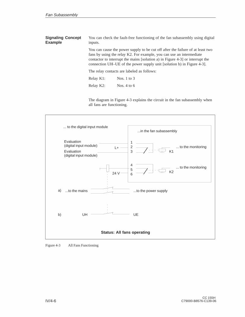
IV/4-6CC 155H
C79000-B8576-C139-06
You can check the fault-free functioning of the fan subassembly using digitalinputs.
You can cause the power supply to be cut off after the failure of at least twofans by using the relay K2. For example, you can use an intermediatecontactor to interrupt the mains [solution a) in Figure 4-3] or interrupt theconnection UH–UE of the power supply unit [solution b) in Figure 4-3].
The relay contacts are labeled as follows:
Relay K1: Nos. 1 to 3
Relay K2: Nos. 4 to 6
The diagram in Figure 4-3 explains the circuit in the fan subassembly whenall fans are functioning.
654
321
L+ ... to the monitoring
... to the monitoring
... to the digital input module
24 V
...to the mains ...to the power supply
...in the fan subassembly
K1
K2
Evaluation(digital input module)
Evaluation(digital input module)
Status: All fans operating
UH UE
a)
b)
Figure 4-3 All Fans Functioning
Signaling ConceptExample
Fan Subassembly

IV/4-7CC 155HC79000-B8576-C139-06
4.3 Changing the Air Flow in the Fan Subassembly
The fan subassembly offers two methods of ventilation: inlet air from behindor from below. For this purpose, there is a cover in the base of the fansubassembly which can be fitted according to the type of ventilationrequired.
The cover is fitted in the base of the fan subassembly. Inlet air flow is frombehind.
Figure 4-4 shows both air flow possibilities.
Inlet air from behind,the cover is fitted inthe base of the fansubassembly
Inlet air from below,the cover is fitted atthe lower back of thefan subassembly
(state when shipped)
Subrack
Fan subassembly
Figure 4-4 Air Flow in the Fan Subassembly
Introduction
When Shipped
Air FlowPossibilities
Fan Subassembly

IV/4-8CC 155H
C79000-B8576-C139-06
To change the air flow, you must refit the cover in the base of the fansubassembly following the steps described below:
1. Using a screwdriver, make a quarter turn counter-clockwise to open thetwo quick-release catches on the front of the fan subassembly.
2. Grasp the base with both hands; press it gently downwards and pull itfully out of the fan subassembly (see Figure 4-5).
3. The cover is secured to the base with snap catches. Press the cover frombelow, close to the snap catches, and remove the cover (see Figure 4-6).
4. At approximately a right angle to the base, insert the cover in the snaphinges at the rear edge of the base.
5. Push the base in again and press it upwards.
6. Using a screwdriver, make a quarter turn clockwise to close the twoquick-release catches.
Figure 4-5 Removing the Base from the Fan Subassembly
Changing the AirFlow
Fan Subassembly

IV/4-9CC 155HC79000-B8576-C139-06
Figure 4-6 shows you both methods of influencing the air flow by fitting thecover in the base of the fan subassembly.
Cover
Quick-release catches
Cover
Snap catches
Snap hinges
cover fitted in base
Cover fitted at rear
(inlet air from behind)
(inlet air from below)
Base
Base
State when shipped:
Figure 4-6 Methods of Ventilation
Fan Subassembly
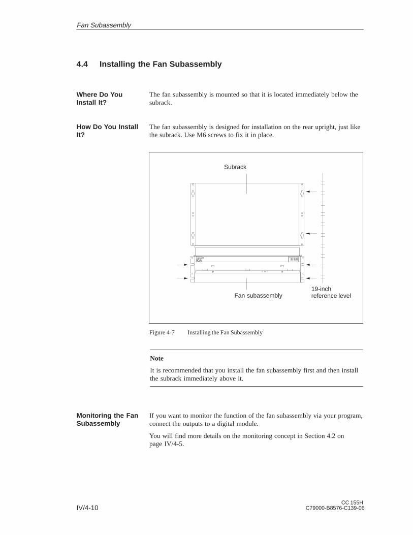
IV/4-10CC 155H
C79000-B8576-C139-06
4.4 Installing the Fan Subassembly
The fan subassembly is mounted so that it is located immediately below thesubrack.
The fan subassembly is designed for installation on the rear upright, just likethe subrack. Use M6 screws to fix it in place.
1AT
19-inchreference level
Subrack
Fan subassembly
Figure 4-7 Installing the Fan Subassembly
Note
It is recommended that you install the fan subassembly first and then installthe subrack immediately above it.
If you want to monitor the function of the fan subassembly via your program,connect the outputs to a digital module.
You will find more details on the monitoring concept in Section 4.2 onpage IV/4-5.
Where Do YouInstall It?
How Do You InstallIt?
Monitoring the FanSubassembly
Fan Subassembly

IV/4-11CC 155HC79000-B8576-C139-06
4.5 Wiring the Fan Subassembly
You have mounted the fan subassembly directly below the subrack.
The following table shows what you should note when wiring up the fansubassembly:
Conductor Conductor CrossSection
Pin-End Connectors Stripped Length
Solidstrands
0.5 to 2.5 mm2 No 8 to 9 mm
Flexibled t
0.5 to 0.75 mm2 Yes,e.g.WAGO209-151conductors
1.0 to 1.5 mm2 Yes,e.g.WAGO209-164 3.5 to 4.5 mm
1.5 to 2.5 mm2 Yes,e.g.WAGO209-157
Proceed as follows:
1. Strip the cores according to the above table. If you are using flexibleconductors, press these with the pin-end connectors.
2. Undo the sprung terminal connections with a suitable screwdriver. Insertthe cores into the terminals on the fan subassembly and pull thescrewdriver out again. Ensure the correct polarity of the mainsconnections.
3. For relieving the strain on the cable you can fix the cable, using a cablebinder, to one of the cable clamping eyes.
Fuse compartment1 AT
L–
L+
Mainsconnections
Eyes for cableclamping
Relay connections
Figure 4-8 Wiring the Fan Subassembly
Initial Situation
Wiring the FanSubassembly
Fan Subassembly

IV/4-12CC 155H
C79000-B8576-C139-06
4.6 Cable Routing When Using the Fan Subassembly
The fan subassembly is used to ventilate and also offers the followingfeatures:
Cable routing
Cable clamping
Shield contact
Depending on the number of cables and connecting lines leading to eachsubrack, the cross section of the fan subassembly may not be sufficient tohold all the cables.
In this case, you should route half the cables to each side via the fansubassembly.
There are eyes for cable clamping on both sides of the fan subassembly (seeFigure 4-2 on page IV/4-3). You can secure the cables to these eyes withcable ties, for example.
The fan subassembly offers the possibility of electrical contact for cableshields. You can use the shielding clamps supplied for this purpose (seeFigure 4-2 on page IV/4-3).
To establish a contact for the cable shields, strip the outer insulation in theregion of the respective shielding clamp and trap the cable shield under theclamp.
Introduction
Cable Routing
Cable Clamping
Shield Contact
Fan Subassembly

IV/4-13CC 155HC79000-B8576-C139-06
4.7 Replacing the Fuse in the Fan Subassembly
The fan subassembly is mounted and wired up. The fuse is defective.
Fusecompartment1 AT
1AT
L–
L+
Figure 4-9 Front View of the Fan Subassembly
Use only the following widely available cartridge fuse link for the fansubassembly:
Fuse type: 1.0 AT for 24 V, 5 x 20 mm conforming to DIN
To change the fuse in the fan subassembly, proceed as follows:
1. Using a screwdriver, twist out the fuse cover (Figure 4-9).
2. Remove the blown fuse from the fuse cover.
3. Insert the new fuse in the fuse cover and twist this back into the fansubassembly.
Initial Situation
Which Fuse DoYou Use?
How Do YouChange the Fuse?
Fan Subassembly

IV/4-14CC 155H
C79000-B8576-C139-06
4.8 Replacing Fans in the Fan Subassemblies during Operation
The fan subassembly is mounted and wired up. A fan is defective. This issignaled by one of the three red LEDs (F1, F2, F3).
Assignment: F 1 = fan 1F 2 = fan 2F 3 = fan 3
Quick-release catchesBase
1AT
ÄÄÄÄÄÄÄÄÄÄ
ÄÄÄÄÄÄÄÄÄÄÄÄ
ÄÄÄÄÄÄÄÄÄÄÄÄ
Fan 1 Fan 2 Fan 3
Figure 4-10 LEDs of the Fan Subassembly
Proceed as follows to replace one of the three fans:
1. Using a screwdriver, make a quarter turn counter-clockwise to open thetwo quick-release catches on the front of the fan subassembly(Figure 4-10).
2. Grasp the base with both hands; press it gently downwards and pull itfully out of the fan subassembly.
3. Release the fan you want to replace by pushing the fan lug (Figure 4-11)away from the casing with your thumb.
Initial Situation
Removing a Fan
Fan Subassembly

IV/4-15CC 155HC79000-B8576-C139-06
Fan
Fan lug
Base
Figure 4-11 Releasing the Fan
4. Pull out the fan you want to replace.
5. Push in the new fan until it snaps into place. The fan starts to run and thefault LED goes out.
6. Push the base in again and press it upwards.
7. Using a screwdriver, make a quarter turn clockwise to close the twoquick-release catches.
Fan Subassembly

IV/4-16CC 155H
C79000-B8576-C139-06
4.9 Replacing the Monitoring PCB of the Fan Subassembly
The fan subassembly is mounted and wired up. The monitoring PCB isdefective.
Proceed as follows to replace the PCB:
1. Disconnect the mains cable of the fan subassembly from the mainsvoltage.
2. Using a screwdriver, make a quarter turn counter-clockwise to open thetwo quick-release catches on the front of the fan subassembly.
3. Remove the base of the fan subassembly (see Figures 4-5 and 4-11).
The figure below shows the front view of the fan subassembly. You can alsosee where the PCB is mounted.
Monitoring PCBQuick-releasecatch
Quick-releasecatch
1AT
ÄÄÄÄÄÄÄÄÄÄ
ÄÄÄÄÄÄÄÄÄÄ
ÄÄÄÄÄÄÄÄÄÄÄÄ
Fan 1 Fan 2 Fan 3
Figure 4-12 Monitoring PCB in the Fan Subassembly
4. Pull the defective PCB forwards out of the fan subassembly.
5. Push the new PCB in until it snaps into place.
6. Push the base in again and press it upwards.
7. Using a screwdriver, make a quarter turn clockwise to close the twoquick-release catches.
8. Connect the mains cable of the fan subassembly to the mains voltage.
!Caution
Electronic components can be destroyed.
If you do not observe the ESD guidelines when handling PCBs withelectronic components, the electronic components may be damaged by staticdischarge.
Observe the ESD guidelines.
Initial Situation
Replacing the PCB
Fan Subassembly

IV/5-1CC 155HC79000-B8576-C139-06
General Technical Data
Section Description Page
5.1 Notes on the CE Mark IV/5-2
5.2 Technical Specifications IV/5-3
Also listed in conjunction with the general technical specifications are thestandards and test values that the modules of the CC 155H conform to andfulfill as well as the test criteria in accordance with which the CC 155H hasbeen tested.
The following approvals exist for the CC 155H:
UL Recognition MarkUnderwriters Laboratories (UL) in accordance withStandard UL 508
CSA Certification MarkCanadian Standard Association (CSA) in accordance withStandard C 22.2 No. 142
The approvals apply if the appropriate labels are visible on all components.
Approvals
5

IV/5-2CC 155H
C79000-B8576-C139-06
5.1 Notes on the CE Mark
All the components of the CC 155H meet the requirements of the standardsin force in Europe provided they are installed in accordance with all theappropriate regulations.
The following applies to the SIMATIC products described in this manual:
Products that carry the CE mark meet the requirements of EC Directive89/336/EEC ‘Electromagnetic Compatibility’.
In accordance with the Article 10 (2) of the above-mentioned EC Directive,the EU declarations of conformity and the relevant documentation are held atthe disposal of the competent authorities at the address below:
Siemens AGAutomation GroupAUT 125Postfach 1963D-92209 Amberg
Products that do not carry the CE mark conform to the requirements andstandards as specified in this manual in the sections entitled “TechnicalSpecifications”.
For SIMATIC S5, the following area of application applies in accordancewith the CE mark:
Area of Application Requirements on
Noise emission Noise immunity
Industry EN 50081-2 : 1993 EN 50082-2 : 1995
The installation guidelines for SIMATIC S5 and the safety-related guidelineswhich appear in this manual should be observed during commissioning andoperation of the CC 155H. The following rules for the use of particularmodules should also be observed.
Programmable controllers of the SIMATIC S5-135U/155U and S5-155Hseries and the CC 155H must be installed in metallic cabinets in accordancewith these installation guidelines.
To protect modules from static discharge, the operator must discharge anystatic electricity from his/her body before opening cabinets.
Introduction
CE Mark
Areas ofApplication
Observe theInstallationGuidelines
Installing theDevices
Working onSwitchgearCabinets
General Technical Data

IV/5-3CC 155HC79000-B8576-C139-06
5.2 Technical Specifications
Unit safety
Device conforms to: VDE 0805, EN 60950, IEC 950, VDE 0160and VDE 0106 part 101
Protection class I
Degree of protection
(if empty slots are covered by dummy front plates)
IP 20 in accordance with IEC 529/DIN 40050
Climatic ambient conditions (tested to DIN IEC 68-2/-1/2/3)
Ambient temperature in operation
(air flow measured at the lower air inlet of thedevice)
0 to 55 C
Transport and storage temperature –40 to 70 C
Temperature change:
during operation
during transport and while in storage(on delivery below 0 C at least 3 h acclimatization time)
max. 10 K/h
max. 20 K/h
Relative humidity:
in operation, during transport and in storagemax. 95% at 25 C, no condensation
Altitude:
in operation
during transport and while in storage
–1000 m to +1500 m above sea level(1080 hPa to 860 hPa)
–1000 m to +3500 m above sea level(1080 hPa to 660 hPa)
Pollutant emissions:
SO2
H2S
0.5 cm3 / m3, 4 days
0.1 cm3 / m3, 4 days
Mechanical ambient conditions (tested to DIN IEC 68-2-6)
Vibration during operation 10 to 50 Hz (constant amplitude 0.075 mm)58 to 500 Hz (constant acceleration 1 g)
General Technical Data

IV/5-4CC 155H
C79000-B8576-C139-06
Noise immunity, electromagnetic compatibility (EMC)
RFI suppression
limit value class
to EN 55011
A 2)
Conducted interference on AC supply lines (230 VAC)
to EN 61000-4-4/IEC 1000-4-4 (Burst)
to IEC 1000-4-5
between two lines (s pulses)
between line and ground (s pulses)
2 kV
1 kV
2 kV
DC supply lines (24 V DC) to EN 61000-4-4/IEC 1000-4-4 (Burst)
2 kV
Signal lines to EN 61000-4-4/IEC 1000-4-4 (Burst)2 kV 1)
Immunity to static discharge to EN 61000-4-2/IEC1000-4-2 (ESD) 2)
Proper installation ensures an interferenceimmunity of 4 kV contact discharge (8 kVatmospheric discharge)
Immunity to electromagnetic high-frequencyradiation 2), pulse-modulated to ENV 50140 /IEC 1004-4-3
80 MHz to 1000 MHz10 V/m80% AM (1 kHz)
Immunity to electromagnetic high-frequencyradiation 2), amplitude-modulated to ENV 50204
900 MHz10 V/m50% ED
Immunity to high-frequency sine-form toENV 50141
0.15 MHz to 80 MHz10 V80% AM
Mechanical data
Mechanical requirements Installation in stationary equipment, subject tovibration; installation on ships and in vehiclesif special installation rules are observed, butnot on the engine
Weight
Subrack
Fan subassembly
approx. 7.5 kg
approx. 2.0 kg
Dimensions (WHD)(subrack plus fan subassembly)
483 mm420 mm270 mm
1) Signal lines that do not serve the process control, e.g. connections to the external I/O etc.: 1 kV2) With cabinet door closed
General Technical Data

S5-155H (CPU 948R)C79000-G8576-C197-06 1
Siemens AG
A&D AS E 81
Oestliche Rheinbrueckenstr. 50
D-76181 Karlsruhe
Federal Republic of Germany
Please check any industry that applies to you:
Automotive
Chemical
Electrical Machinery
Food
Instrument and Control
Nonelectrical Machinery
Petrochemical
Pharmaceutical
Plastic
Pulp and Paper
Textiles
Transportation
Other _ _ _ _ _ _ _ _ _ _ _
From:
Your Name:_ _ _ _ _ _ _ _ _ _ _ _ _ _ _ _ _ _ _ _ _ _ _ _ _ _ _ _ _
Your Title: _ _ _ _ _ _ _ _ _ _ _ _ _ _ _ _ _ _ _ _ _ _ _ _ _ _ _ _ _
Company Name: _ _ _ _ _ _ _ _ _ _ _ _ _ _ _ _ _ _ _ _ _ _ _ _ _ _
Street: _ _ _ _ _ _ _ _ _ _ _ _ _ _ _ _ _ _ _ _ _ _ _ _ _ _
City, Zip Code_ _ _ _ _ _ _ _ _ _ _ _ _ _ _ _ _ _ _ _ _ _ _ _ _ _
Country: _ _ _ _ _ _ _ _ _ _ _ _ _ _ _ _ _ _ _ _ _ _ _ _ _ _
Phone: _ _ _ _ _ _ _ _ _ _ _ _ _ _ _ _ _ _ _ _ _ _ _ _ _ _

2S5-155H (CPU 948R)
C79000-G8576-C197-06
Additional comments:
_ _ _ _ _ _ _ _ _ _ _ _ _ _ _ _ _ _ _ _ _ _ _ _ _ _ _ _ _ _ _ _ _ _ _
_ _ _ _ _ _ _ _ _ _ _ _ _ _ _ _ _ _ _ _ _ _ _ _ _ _ _ _ _ _ _ _ _ _ _
_ _ _ _ _ _ _ _ _ _ _ _ _ _ _ _ _ _ _ _ _ _ _ _ _ _ _ _ _ _ _ _ _ _ _
_ _ _ _ _ _ _ _ _ _ _ _ _ _ _ _ _ _ _ _ _ _ _ _ _ _ _ _ _ _ _ _ _ _ _
_ _ _ _ _ _ _ _ _ _ _ _ _ _ _ _ _ _ _ _ _ _ _ _ _ _ _ _ _ _ _ _ _ _ _
_ _ _ _ _ _ _ _ _ _ _ _ _ _ _ _ _ _ _ _ _ _ _ _ _ _ _ _ _ _ _ _ _ _ _
_ _ _ _ _ _ _ _ _ _ _ _ _ _ _ _ _ _ _ _ _ _ _ _ _ _ _ _ _ _ _ _ _ _ _
_ _ _ _ _ _ _ _ _ _ _ _ _ _ _ _ _ _ _ _ _ _ _ _ _ _ _ _ _ _ _ _ _ _ _
_ _ _ _ _ _ _ _ _ _ _ _ _ _ _ _ _ _ _ _ _ _ _ _ _ _ _ _ _ _ _ _ _ _ _
_ _ _ _ _ _ _ _ _ _ _ _ _ _ _ _ _ _ _ _ _ _ _ _ _ _ _ _ _ _ _ _ _ _ _
_ _ _ _ _ _ _ _ _ _ _ _ _ _ _ _ _ _ _ _ _ _ _ _ _ _ _ _ _ _ _ _ _ _ _
_ _ _ _ _ _ _ _ _ _ _ _ _ _ _ _ _ _ _ _ _ _ _ _ _ _ _ _ _ _ _ _ _ _ _
Remarks Form
Your comments and recommendations will help us to improve the quality and usefulnessof our publications. Please take the first available opportunity to fill out this questionnaireand return it to Siemens.
Please give each of the following questions your own personal mark within the rangefrom 1 (very good) to 5 (poor).
1. Do the contents meet your requirements?
2. Is the information you need easy to find?
3. Is the text easy to understand?
4. Does the level of technical detail meet your requirements?
5. Please rate the quality of the graphics/tables: