simatic s7 ethernet driver for jmobile - esco-da.be uniop/technotes/ptn0378-8.pdf · tech-note...
TRANSCRIPT

Tech-note
Simatic S7 Ethernet
driver for JMobile
This Technical Note contains the information needed to connect the system to Siemens
Simatic S7 controllers on the Ethernet network using the Simatic protocol.
Exor international S.p.A. Ptn0378 Ver. 1.08

Tech-note
ptn0378-8.doc - 28.05.2015 Simatic S7 Ethernet driver for JMobile
2
Copyright 2015 EXOR International S.p.A. – Verona, Italy Subject to change without notice The information contained in this document is provided for informational purposes only. While efforts were made to verify the accuracy of the information contained in this documentation, it is provided “as is” without warranty of any kind. Third-party brands and names are the property of their respective owners. www.exorint.net

Tech-note
ptn0378-8.doc - 28.05.2015 Simatic S7 Ethernet driver for JMobile
3
Contents
Simatic S7 Ethernet Driver ............................................................................................................. 4 Protocol editor settings...................................................................................................... 5 Tag editor settings ............................................................................................................. 6 Tag import for Simatic Step7 ............................................................................................ 8 Tag import for TIA Portal ................................................................................................. 14 Aliasing tag names in PLC network configuration .......................................................... 19 String data type ............................................................................................................... 20 Simatic S5timer data type ............................................................................................... 23 Special data type ............................................................................................................. 25 S7-1200 and S7-1500 PLC Configuration ...................................................................... 26 Logo! PLC Configuration ................................................................................................. 28 Communication status ..................................................................................................... 29
Tech-note
ptn0378-8.doc - 28.05.2015 Simatic S7 Ethernet driver for JMobile
4
Simatic S7 Ethernet Driver
The Simatic controller must either have an on-board Ethernet port or be equipped with an appropriate Ethernet interface (either built-in or with a module). The communication is based on the PG/OP (ISO on TCP) communication functions. The chapter describes settings for the driver to be applied in programming IDE software and in S7 PLC programming software.
Document code ptn0378 Version 1.08
Tech-note
ptn0378-8.doc - 28.05.2015 Simatic S7 Ethernet driver for JMobile
5
Protocol editor settings
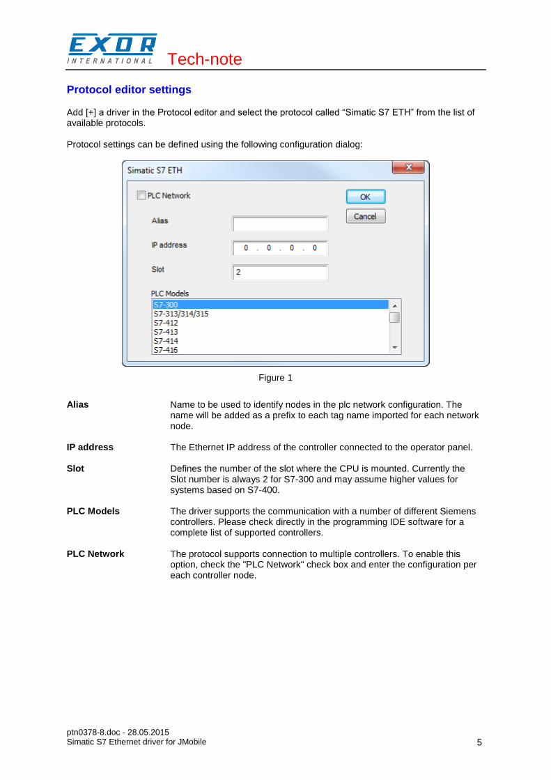
Add [+] a driver in the Protocol editor and select the protocol called “Simatic S7 ETH” from the list of available protocols. Protocol settings can be defined using the following configuration dialog:
Figure 1
Alias Name to be used to identify nodes in the plc network configuration. The
name will be added as a prefix to each tag name imported for each network node.
IP address The Ethernet IP address of the controller connected to the operator panel.
Slot Defines the number of the slot where the CPU is mounted. Currently the Slot number is always 2 for S7-300 and may assume higher values for systems based on S7-400.
PLC Models The driver supports the communication with a number of different Siemens controllers. Please check directly in the programming IDE software for a complete list of supported controllers.
PLC Network The protocol supports connection to multiple controllers. To enable this option, check the "PLC Network" check box and enter the configuration per each controller node.

Tech-note
ptn0378-8.doc - 28.05.2015 Simatic S7 Ethernet driver for JMobile
6
Tag editor settings
Into Tag editor select the protocol “Simatic S7 ETH” from the list of defined protocols and add a tag using [+] button. Tag settings can be defined using the following dialog:
Figure 2
Memory Type Area of PLC where tag is located.
Data Type Simatic Type
Internal Memory M
Data Block DB
Input I (E)
Output O (A)
Timer value T
Counter value C
Offset Offset address where tag is located.
SubIndex This allows resource offset selection within the register.
Data Block If Memory Type is “Data Block”, this will identify the DB number.
Data Type Data Type Memory Space Limits
boolean 1 bit data 0 ... 1
byte 8-bit data -128 ... 127
short 16-bit data -32768 ... 32767
int 32-bit data -2.1e9 ... 2.1e9
unsignedByte 8-bit data 0 ... 255

Tech-note
ptn0378-8.doc - 28.05.2015 Simatic S7 Ethernet driver for JMobile
7
unsignedShort 16-bit data 0 ... 65535
unsignedInt 32-bit data 0 ... 4.2e9
float IEEE single-precision 32-bit floating point type
1.17e-38 ... 3.40e38
string Refer to “String data type chapter”
NOTE: to define arrays, select one of Data Type format followed by square brackets like “byte[]”, “short[]”…
Arraysize When configuring array or string tags, this option define the amount of array
elements or characters of the string.
Conversion Conversion to be applied.
Value
Inv bits Invert a bit (boolean tag)
Negate Invert all bits
AB -> BA Swap nibbles of a byte
ABCD -> CDAB Swap bytes of a word
ABCDEFGH -> GHEFCDAB Swap bytes of a double word
BCD BCD format conversion
S5timer(BCD) S5 Timer in BCD format
S5timer(BIN) S5 Timer in binary format

Tech-note
ptn0378-8.doc - 28.05.2015 Simatic S7 Ethernet driver for JMobile
8
Tag import for Simatic Step7
The Simatic S7 Ethernet tag import filter accepts symbol files with extension “.asc” and “.awl” created by the Simatic Step7. The “.asc” file can be exported from the symbol table utility. See in Figure 3 how to access the Symbol Table from the Step7 programming software.
Figure 3
From the “Symbol Editor”, click then on the “Symbol Table” menu and select “Export...”. Assign a name and save the ASCII file as shown in figure.
Figure 4

Tech-note
ptn0378-8.doc - 28.05.2015 Simatic S7 Ethernet driver for JMobile
9
The “.awl” file comes from the export operation of the Source code. Open any program block in the editor, for example OB1. Click on “File” menu and select “Generate Source…” You will get the dialog box shown in Figure 5:
Figure 5
Define a name (in the example is “Sources”) and click OK.

Tech-note
ptn0378-8.doc - 28.05.2015 Simatic S7 Ethernet driver for JMobile
10
In “Generate source Sources” dialog - click [All >] button to select source generation for all blocks, - mark “include reference blocks” and “Sort according to program structure” checkboxes - choose “Symbolic” addresses
then confirm with OK.
Figure 6

Tech-note
ptn0378-8.doc - 28.05.2015 Simatic S7 Ethernet driver for JMobile
11
This will generate an object called “Sources” (the name given before) accessible from the “Sources” folder of the Step7 project as shown in the following figure.
Figure 7
Right click on the object and select “Export Sources...” This will allow you obtaining the “.awl” file to be imported in the Tag Editor.
Figure 8

Tech-note
ptn0378-8.doc - 28.05.2015 Simatic S7 Ethernet driver for JMobile
12
NOTE: the “.awl” file contains additional information not included in the “.asc” file exported from the Symbol Table; to make sure they are properly imported, a reference to the block should be inserted in the Symbol Table. For example, the tags from a data block are imported only if the symbol table contains a line with the data block name and related comment as shown in the following figure.
Figure 9 The entry indicated in will Figure 9 enable the import filter to import the tags related to the specific data block.
After “.awl” and “.asc” creation, click on the Import tag button “ >] ” to start the importer. Select Import type “ *.asc ”, then locate the “.asc” file and “.awl” files and confirm. They are both required to have the full information about all the data types used.
Figure 10

Tech-note
ptn0378-8.doc - 28.05.2015 Simatic S7 Ethernet driver for JMobile
13
Tags present in the exported files are listed in the tag dictionary from where they can be directly added to the project using the add tags button as shown in the following figure
Figure 11

Tech-note
ptn0378-8.doc - 28.05.2015 Simatic S7 Ethernet driver for JMobile
14
Tag import for TIA Portal
The Simatic S7 Ethernet tag import filter accepts symbol files with extension “.tia” and “.xlsx” exported from TIA Portal programming software. The “.tia” files refer to DB tags defined under "Program blocks", to import them follow these steps: 1. Configure the Data Block as “Not optimized”.
With right click on Data Block name select Properties:
Figure 12

Tech-note
ptn0378-8.doc - 28.05.2015 Simatic S7 Ethernet driver for JMobile
15
Tab General > Attributes uncheck "Optimized block access" as below:
Figure 13
NOTE: If checkbox "optimized block access" is not available (grayed out) could due to DB is an "instance DB" linked to an "optimized access FB".
2. Compile project to ensure TIA Portal calculate tags offset:
Figure 14
3. Export DB tags for every Program Block: a) Double click on DB name b) Expand the view of program block selected c) Highlight all row into this view (CTRL + A to select all rows) d) Copy into clipboard ( CTRL + C ) e) Open a Text editor and paste the clipboard content ( CTRL + V)

Tech-note
ptn0378-8.doc - 28.05.2015 Simatic S7 Ethernet driver for JMobile
16
Figure 15
f) Save the file as "DBxxx.tia", where xxx=number of DB.
NOTE: saving text file with Notepad with extension ".tia" pay attention to select "Save as type" as "All Files" otherwise the file will be named DB2.tia.txt and will not be visible from importer.
The “.xlsx” file refers to “PLC tags”, to import them follow these steps: 1. Double click on "Show all tags" to open tag table 2. Click on “Export” button and browse for path file 3. Define file name
Figure 16

Tech-note
ptn0378-8.doc - 28.05.2015 Simatic S7 Ethernet driver for JMobile
17
4. Confirm with “Save”
Figure 17
5. Export with “OK”
Figure 18
Tech-note
ptn0378-8.doc - 28.05.2015 Simatic S7 Ethernet driver for JMobile
18
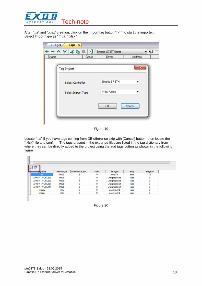
After “.tia” and “.xlsx” creation, click on the Import tag button “ >] ” to start the importer. Select Import type as “ *.tia; *.xlsx ”
Figure 19
Locate “.tia” if you have tags coming from DB otherwise skip with [Cancel] button, then locate the “.xlsx” file and confirm. The tags present in the exported files are listed in the tag dictionary from where they can be directly added to the project using the add tags button as shown in the following figure
Figure 20

Tech-note
ptn0378-8.doc - 28.05.2015 Simatic S7 Ethernet driver for JMobile
19
Aliasing tag names in PLC network configuration
Tag names must be unique at project level; it often happens that the same tag names are to be used for different controller nodes (for example when the HMI is connected to two devices that are running the same application). Since tags include also the identification of the node and Tag Editor does not support duplicate tag names, the import facility in Tag Editor has an aliasing feature that can automatically add a prefix to imported tags. With this feature tag names can be done unique at project level. The feature works when importing tags for a specific protocol. Each tag name will be prefixed with the string specified by the “Alias”. As shown in the figure below, the connection to a certain controller is assigned the name “Node1”. When tags are imported for this node, all tag names will have the prefix “Node1” making each of them unique at the network/project level.
Figure 21
NOTE: Aliasing tag names are only available when tags can be imported. Tags which are added manually in the Tag Editor do not need to have the Alias prefix in the tag name. The Alias string is attached to the tag name only at the moment the tags are imported using Tag Editor. If the Alias string is modified after the tag import has been completed, there will be no effect on the names already present in the dictionary. When the Alias string is changed and tags are imported again, all tags will be imported again with the new prefix string.

Tech-note
ptn0378-8.doc - 28.05.2015 Simatic S7 Ethernet driver for JMobile
20
String data type
In Simatic S7 PLC it's possible to define two different types of tags to manage string variables. - as Array [1..xx] of Chars. - as String[xx].
Step7 string declaration is showed in Figure 22:
Figure 22
TIA Portal string declaration is showed in Figure 23:
Figure 23
NOTE: Usage of String[xx] data type is allowed but a specific Conversion must be applied to the tag. Anyway using tag importer to import tag dictionary from TIA Portal or Step7 string tags are automatically configured and no changes/conversion are needed.

Tech-note
ptn0378-8.doc - 28.05.2015 Simatic S7 Ethernet driver for JMobile
21
To manually add an "Array [1..xx] of Chars" data type tag, press the [+] button in the Tag Editor, then select "string" as Data Type of the Tag and type the string length in the "Arraysize" field:
Figure 24
and confirm with OK button.
To manually add a "String[xx]" data type tag, press the [+] button in the Tag Editor, then select "string" as Data Type of the Tag and type the string length in the "Arraysize" field,
Figure 25

Tech-note
ptn0378-8.doc - 28.05.2015 Simatic S7 Ethernet driver for JMobile
22
then click on [+/-] button to open the Conversion dialog.
Figure 26
Into conversion dialog: - select the "S7 String" conversion type. - click on [+] button to add the conversion.
Figure 27
The conversion will be listed into the Configured window on the right. Confirm with OK button.

Tech-note
ptn0378-8.doc - 28.05.2015 Simatic S7 Ethernet driver for JMobile
23
Simatic S5timer data type
Simatic drivers support a special data type, called S5Timer. The tag must be configured with a specific data type and a conversion must be applied to the Tag to correctly read/write a Simatic S5Timer Variable.
Open the Tag Editor and add a Tag pressing the Plus button.
Figure 28
Select “unsignedInt” as Data Type of the Tag.
Figure 29

Tech-note
ptn0378-8.doc - 28.05.2015 Simatic S7 Ethernet driver for JMobile
24
Click on +/- button to open the Conversion dialog.
Figure 30
In the Conversion dialog select the S5timer(BCD) conversion type [A] then click on Plus button [B] to add the conversion, the configured conversion will be listed into the Configured window on the right. Then confirm with OK.
Figure 31

Tech-note
ptn0378-8.doc - 28.05.2015 Simatic S7 Ethernet driver for JMobile
25
Special data type
The Simatic S7 Ethernet driver provides a special data type called "Node Override IP". The Node override IP allows changing at run time the IP address of the target controller. This memory type is an array of 4 unsigned bytes, one per each byte of the IP address. The Node Override IP is initialized with the value of the controller IP specified in the project at programming time. If the Node Override IP is set to 0.0.0.0, all the communication with the slave is stopped, no request frames are generated anymore. If the Node Override IP has a value different from 0.0.0.0, it is interpreted as node IP override and the target IP address is replaced run-time with the new value. In case the panel has been configured to access to a network of controllers, each node has its own Node Override IP variable. Note: the Node Override IP values assigned at run-time are retained through power cycles
Figure 32

Tech-note
ptn0378-8.doc - 28.05.2015 Simatic S7 Ethernet driver for JMobile
26
S7-1200 and S7-1500 PLC Configuration
The S7-1200 (starting from firmware version 4.0) and S7-1500 plc series from Siemens has a built-in firewall, by default the maximum protection level is enabled. To establish communication with these plc models it is necessary to enable S7 communications with 3
rd party devices, this setting is available from TIA Portal programming software, as explained in the
following section. 1. Open the PLC project in the TIA Portal software.
2. Select the PLC from the project tree and open the PLC Properties.
Figure 33

Tech-note
ptn0378-8.doc - 28.05.2015 Simatic S7 Ethernet driver for JMobile
27
3. In the “General” tab, select “Protection” and make sure “Full access (no protection)” is selected.
Figure 34
4. Then scroll down the page and check “Permit access with PUT/GET communication from remote partner (PLC, HMI, OPC,…)” option.
Figure 35

Tech-note
ptn0378-8.doc - 28.05.2015 Simatic S7 Ethernet driver for JMobile
28
Logo! PLC Configuration
The communication with Logo! PLC requires a specific configuration, to set-up the PLC for proper communication please follow these steps: 1. Open the Logo!Soft Comfort project, then select Tools > Ethernet connections.
Into the Configure Ethernet Connections dialog right click on Ethernet Connections voice and add a server connection.
Figure 36
2. Double click on the newly created connection to open the connection properties, inside the dialog
select the “Connect with an operator panel (OP)” and the “Accept all connection requests” options, then into the Remote Properties (Client) section enter 02.00 into the TSAP field.
Figure 37
Tech-note
ptn0378-8.doc - 28.05.2015 Simatic S7 Ethernet driver for JMobile
29
Communication status
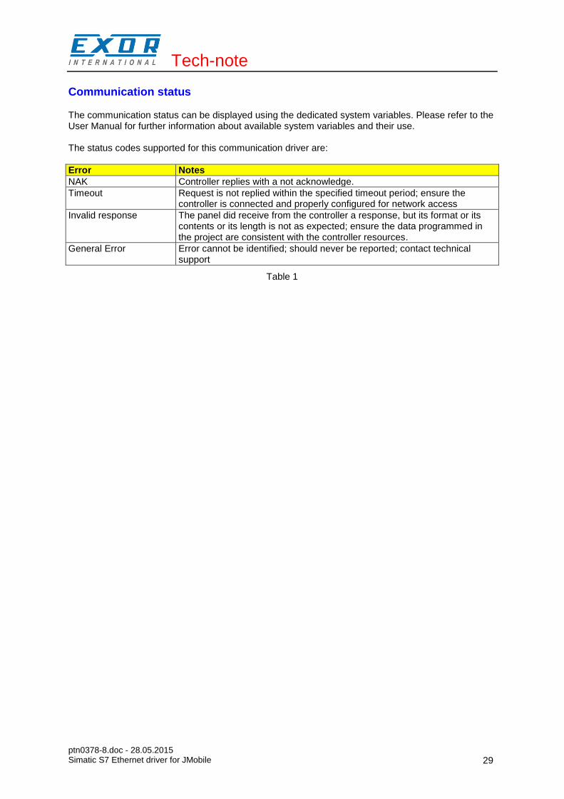
The communication status can be displayed using the dedicated system variables. Please refer to the User Manual for further information about available system variables and their use. The status codes supported for this communication driver are:
Error Notes
NAK Controller replies with a not acknowledge.
Timeout Request is not replied within the specified timeout period; ensure the controller is connected and properly configured for network access
Invalid response The panel did receive from the controller a response, but its format or its contents or its length is not as expected; ensure the data programmed in the project are consistent with the controller resources.
General Error Error cannot be identified; should never be reported; contact technical support
Table 1