simatic ti505 386/atm coprocessor386/atm coprocessor user manual preface ix preface this manual...
TRANSCRIPT

SIMATIC TI505
386/ATM Coprocessor
User Manual
Order Number: PPX:505-ATM-MANL-3Manual Assembly Number: 2586546–0056Third Edition
SIMATIC is a registered trademark of Siemens AG.
386/ATM is a registered trademark of Siemens Industrial Automation, Inc.
Series 505, Series 500, CVU10000, CVU100, TISOFT, and TISOFT2 are trademarks of Siemens Industrial Automation, Inc.
Intel is a registered trademark of Intel Incorporated.
Centronics is a registered trademark of Centronics Data Computer Corporation.
IBM and AT are registered trademarks of International Business Machines Corporation.
Microsoft, MS-DOS, and GW-BASIC are registered trademarks of Microsoft Corporation.
QBasic (QuickBASIC) is a trademark of Microsoft Corporation.
Texas Instruments and TI are registered trademarks of Texas Instruments Incorporated.
TI505, TI525, TI530C, TI535, TI545, TI555, TI560T, and TI565T, are trademarks of Texas Instruments Incorporated.
Turbo C is a registered trademark of Borland International, Inc.
UL is a registered trademark of Underwriters Laboratories.

01/21/92
Copyright 1993 by Siemens Industrial Automation, Inc.All Rights Reserved — Printed in USA
Reproduction, transmission or use of this document orcontents is not permitted without express consent ofSiemens Industrial Automation, Inc. All rights, including rightscreated by patent grant or registration of a utility model ordesign, are reserved.
Since Siemens Industrial Automation, Inc. does not possessfull access to data concerning all of the uses and applicationsof customer’s products, we do not assume responsibility eitherfor customer product design or for any infringements of patentsor rights of others which may result from our assistance.
Technical data is subject to change.
We check the contents of every manual for accuracy at thetime it is approved for printing; however, there may beundetected errors. Any errors found will be corrected insubsequent editions. Any suggestions for improvement arewelcomed.
MANUAL PUBLICATION HISTORY
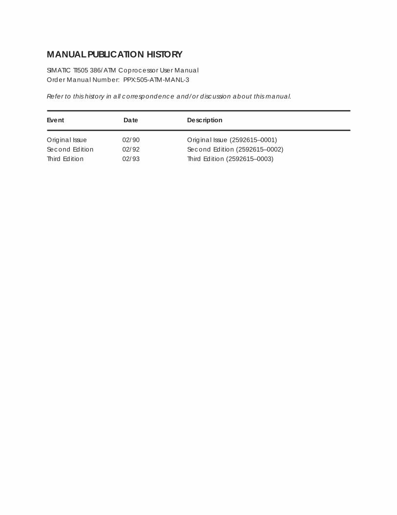
SIMATIC TI505 386/ATM Coprocessor User ManualOrder Manual Number: PPX:505-ATM-MANL-3
Refer to this history in all correspondence and/or discussion about this manual.
Event Date Description
Original Issue 02/90 Original Issue (2592615–0001)Second Edition 02/92 Second Edition (2592615–0002)Third Edition 02/93 Third Edition (2592615–0003)
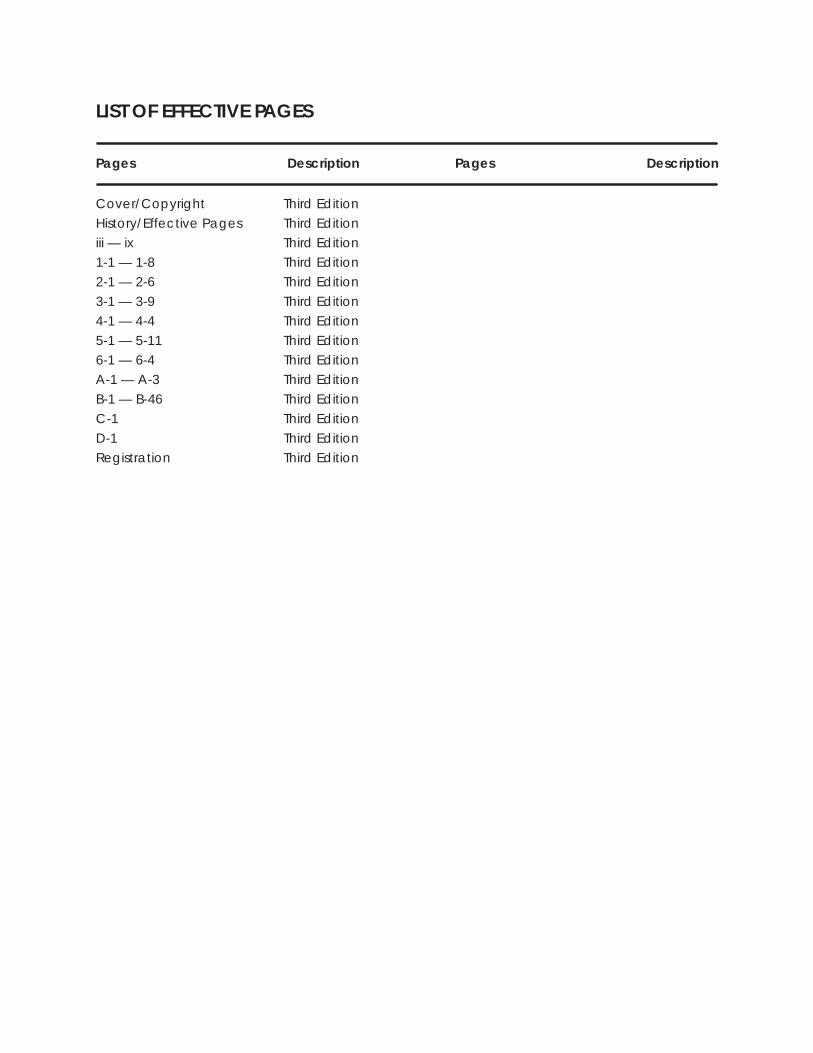
LIST OF EFFECTIVE PAGES
Pages Description Pages Description
Cover/Copyright Third EditionHistory/Effective Pages Third Editioniii — ix Third Edition1-1 — 1-8 Third Edition2-1 — 2-6 Third Edition
3-1 — 3-9 Third Edition4-1 — 4-4 Third Edition5-1 — 5-11 Third Edition6-1 — 6-4 Third EditionA-1 — A-3 Third EditionB-1 — B-46 Third Edition
C-1 Third EditionD-1 Third EditionRegistration Third Edition

Contents iii
Contents
Preface
Chapter 1 Module Features1.1 Overview 1-2. . . . . . . . . . . . . . . . . . . . . . . . . . . . . . . . . . . . . . . . . . . . . . . . . . . . . . . . . . . . . . . . . . . . . . .
Description 1-2. . . . . . . . . . . . . . . . . . . . . . . . . . . . . . . . . . . . . . . . . . . . . . . . . . . . . . . . . . . . . . . . . . . . . Using the 386/ATM Coprocessor 1-2. . . . . . . . . . . . . . . . . . . . . . . . . . . . . . . . . . . . . . . . . . . . . . . . . Applications 1-3. . . . . . . . . . . . . . . . . . . . . . . . . . . . . . . . . . . . . . . . . . . . . . . . . . . . . . . . . . . . . . . . . . . .
1.2 Features 1-5. . . . . . . . . . . . . . . . . . . . . . . . . . . . . . . . . . . . . . . . . . . . . . . . . . . . . . . . . . . . . . . . . . . . . . . .
1.3 Standard Kit Part Lists 1-7. . . . . . . . . . . . . . . . . . . . . . . . . . . . . . . . . . . . . . . . . . . . . . . . . . . . . . . . . . . . PPX:505–ATM–0220 1-7. . . . . . . . . . . . . . . . . . . . . . . . . . . . . . . . . . . . . . . . . . . . . . . . . . . . . . . . . . . . . . PPX:505–ATM–0440 1-7. . . . . . . . . . . . . . . . . . . . . . . . . . . . . . . . . . . . . . . . . . . . . . . . . . . . . . . . . . . . . . PPX:505–ATM–4120 1-7. . . . . . . . . . . . . . . . . . . . . . . . . . . . . . . . . . . . . . . . . . . . . . . . . . . . . . . . . . . . . . Spare Parts 1-7. . . . . . . . . . . . . . . . . . . . . . . . . . . . . . . . . . . . . . . . . . . . . . . . . . . . . . . . . . . . . . . . . . . . .
1.4 Recommended Order of Tasks 1-8. . . . . . . . . . . . . . . . . . . . . . . . . . . . . . . . . . . . . . . . . . . . . . . . . . .
Chapter 2 Installing the Module2.1 Overview of Installation 2-2. . . . . . . . . . . . . . . . . . . . . . . . . . . . . . . . . . . . . . . . . . . . . . . . . . . . . . . . .
Handling the Module 2-2. . . . . . . . . . . . . . . . . . . . . . . . . . . . . . . . . . . . . . . . . . . . . . . . . . . . . . . . . . . Visual Inspection 2-2. . . . . . . . . . . . . . . . . . . . . . . . . . . . . . . . . . . . . . . . . . . . . . . . . . . . . . . . . . . . . . . . Technical Assistance 2-2. . . . . . . . . . . . . . . . . . . . . . . . . . . . . . . . . . . . . . . . . . . . . . . . . . . . . . . . . . . . Flow of Tasks 2-3. . . . . . . . . . . . . . . . . . . . . . . . . . . . . . . . . . . . . . . . . . . . . . . . . . . . . . . . . . . . . . . . . . . .
2.2 Configuring the Module 2-4. . . . . . . . . . . . . . . . . . . . . . . . . . . . . . . . . . . . . . . . . . . . . . . . . . . . . . . . .
2.3 Inserting the Module into the Base 2-5. . . . . . . . . . . . . . . . . . . . . . . . . . . . . . . . . . . . . . . . . . . . . . . Inserting the Module 2-5. . . . . . . . . . . . . . . . . . . . . . . . . . . . . . . . . . . . . . . . . . . . . . . . . . . . . . . . . . . . Power Requirements 2-5. . . . . . . . . . . . . . . . . . . . . . . . . . . . . . . . . . . . . . . . . . . . . . . . . . . . . . . . . . . .
2.4 Connecting Peripherals 2-6. . . . . . . . . . . . . . . . . . . . . . . . . . . . . . . . . . . . . . . . . . . . . . . . . . . . . . . . . Monitor 2-6. . . . . . . . . . . . . . . . . . . . . . . . . . . . . . . . . . . . . . . . . . . . . . . . . . . . . . . . . . . . . . . . . . . . . . . . Keyboard 2-6. . . . . . . . . . . . . . . . . . . . . . . . . . . . . . . . . . . . . . . . . . . . . . . . . . . . . . . . . . . . . . . . . . . . . . Communications 2-6. . . . . . . . . . . . . . . . . . . . . . . . . . . . . . . . . . . . . . . . . . . . . . . . . . . . . . . . . . . . . . . Printer 2-6. . . . . . . . . . . . . . . . . . . . . . . . . . . . . . . . . . . . . . . . . . . . . . . . . . . . . . . . . . . . . . . . . . . . . . . . . .
Chapter 3 Loading System Software3.1 Overview 3-2. . . . . . . . . . . . . . . . . . . . . . . . . . . . . . . . . . . . . . . . . . . . . . . . . . . . . . . . . . . . . . . . . . . . . . .
Potential for Errors During Diskette Access 3-3. . . . . . . . . . . . . . . . . . . . . . . . . . . . . . . . . . . . . . . .
3.2 Setting System Parameters 3-4. . . . . . . . . . . . . . . . . . . . . . . . . . . . . . . . . . . . . . . . . . . . . . . . . . . . . .
iv Contents
3.3 Preparing the Hard Disk and Loading MS-DOS 3-5. . . . . . . . . . . . . . . . . . . . . . . . . . . . . . . . . . . . Booting the Module from the Diskette 3-5. . . . . . . . . . . . . . . . . . . . . . . . . . . . . . . . . . . . . . . . . . . .
3.4 Installing System Software 3-6. . . . . . . . . . . . . . . . . . . . . . . . . . . . . . . . . . . . . . . . . . . . . . . . . . . . . . . Copying Software to the Hard Disk 3-6. . . . . . . . . . . . . . . . . . . . . . . . . . . . . . . . . . . . . . . . . . . . . . . Typical ATM Driver Files 3-7. . . . . . . . . . . . . . . . . . . . . . . . . . . . . . . . . . . . . . . . . . . . . . . . . . . . . . . . . . Installing Sample Programs 3-8. . . . . . . . . . . . . . . . . . . . . . . . . . . . . . . . . . . . . . . . . . . . . . . . . . . . . . Loading System Device Drivers 3-8. . . . . . . . . . . . . . . . . . . . . . . . . . . . . . . . . . . . . . . . . . . . . . . . . .
3.5 What Next? 3-9. . . . . . . . . . . . . . . . . . . . . . . . . . . . . . . . . . . . . . . . . . . . . . . . . . . . . . . . . . . . . . . . . . . . . Running the 386/ATM with Third-party Device Drivers and Memory Managers 3-9. . . . . .
Chapter 4 Running TISOFT on the 386/ATM4.1 Logging the 386/ATM into the PLC I/O Configuration Table 4-2. . . . . . . . . . . . . . . . . . . . . . . .
Overview 4-2. . . . . . . . . . . . . . . . . . . . . . . . . . . . . . . . . . . . . . . . . . . . . . . . . . . . . . . . . . . . . . . . . . . . . . . Loading TISOFT2 4-2. . . . . . . . . . . . . . . . . . . . . . . . . . . . . . . . . . . . . . . . . . . . . . . . . . . . . . . . . . . . . . . . Verifying 386ATM.EXE in your Root Directory 4-2. . . . . . . . . . . . . . . . . . . . . . . . . . . . . . . . . . . . . . . Communicating with the PLC 4-3. . . . . . . . . . . . . . . . . . . . . . . . . . . . . . . . . . . . . . . . . . . . . . . . . . . Running TISOFT2 4-3. . . . . . . . . . . . . . . . . . . . . . . . . . . . . . . . . . . . . . . . . . . . . . . . . . . . . . . . . . . . . . . . Selecting the I/O Definition Chart 4-4. . . . . . . . . . . . . . . . . . . . . . . . . . . . . . . . . . . . . . . . . . . . . . . . Viewing the I/O Configuration Chart 4-4. . . . . . . . . . . . . . . . . . . . . . . . . . . . . . . . . . . . . . . . . . . . .
Chapter 5 PLC Communications5.1 Overview 5-2. . . . . . . . . . . . . . . . . . . . . . . . . . . . . . . . . . . . . . . . . . . . . . . . . . . . . . . . . . . . . . . . . . . . . . .
Communicating with the PLC 5-2. . . . . . . . . . . . . . . . . . . . . . . . . . . . . . . . . . . . . . . . . . . . . . . . . . . Verifying the CONFIG.SYS File in your Root Directory 5-2. . . . . . . . . . . . . . . . . . . . . . . . . . . . . . . Using PCCOMM 5-3. . . . . . . . . . . . . . . . . . . . . . . . . . . . . . . . . . . . . . . . . . . . . . . . . . . . . . . . . . . . . . . . Application Program I/O Bus Communication 5-3. . . . . . . . . . . . . . . . . . . . . . . . . . . . . . . . . . . .
5.2 Communicating during PLC Scan: I/O Cycle 5-4. . . . . . . . . . . . . . . . . . . . . . . . . . . . . . . . . . . . . Accessing I/O Points 5-4. . . . . . . . . . . . . . . . . . . . . . . . . . . . . . . . . . . . . . . . . . . . . . . . . . . . . . . . . . . . Command Syntax: IOREAD 5-5. . . . . . . . . . . . . . . . . . . . . . . . . . . . . . . . . . . . . . . . . . . . . . . . . . . . . . Response Syntax: IOREAD 5-5. . . . . . . . . . . . . . . . . . . . . . . . . . . . . . . . . . . . . . . . . . . . . . . . . . . . . . . Command Syntax: IOWRITE 5-6. . . . . . . . . . . . . . . . . . . . . . . . . . . . . . . . . . . . . . . . . . . . . . . . . . . . . Response Syntax: IOWRITE 5-6. . . . . . . . . . . . . . . . . . . . . . . . . . . . . . . . . . . . . . . . . . . . . . . . . . . . . . .
5.3 Communicating with the PLC Scan: Special Function Cycle 5-7. . . . . . . . . . . . . . . . . . . . . . . Description 5-7. . . . . . . . . . . . . . . . . . . . . . . . . . . . . . . . . . . . . . . . . . . . . . . . . . . . . . . . . . . . . . . . . . . . . Command Syntax: PCREAD 5-8. . . . . . . . . . . . . . . . . . . . . . . . . . . . . . . . . . . . . . . . . . . . . . . . . . . . . Response Syntax: PCREAD 5-8. . . . . . . . . . . . . . . . . . . . . . . . . . . . . . . . . . . . . . . . . . . . . . . . . . . . . . . Command Syntax: PCWRITE 5-9. . . . . . . . . . . . . . . . . . . . . . . . . . . . . . . . . . . . . . . . . . . . . . . . . . . . . Response Syntax: PCWRITE 5-9. . . . . . . . . . . . . . . . . . . . . . . . . . . . . . . . . . . . . . . . . . . . . . . . . . . . . . Executing Commands from a File 5-9. . . . . . . . . . . . . . . . . . . . . . . . . . . . . . . . . . . . . . . . . . . . . . . . Notes Concerning Writing to Memory Locations 5-10. . . . . . . . . . . . . . . . . . . . . . . . . . . . . . . . . .
5.4 Communicating with the PLC: COMM Port Cycle 5-11. . . . . . . . . . . . . . . . . . . . . . . . . . . . . . . . . Serial Port to PLC 5-11. . . . . . . . . . . . . . . . . . . . . . . . . . . . . . . . . . . . . . . . . . . . . . . . . . . . . . . . . . . . . . . . RS-232 Com1 and Com2 5-11. . . . . . . . . . . . . . . . . . . . . . . . . . . . . . . . . . . . . . . . . . . . . . . . . . . . . . . .
Contents v
Chapter 6 Troubleshooting6.1 Diagnostics 6-2. . . . . . . . . . . . . . . . . . . . . . . . . . . . . . . . . . . . . . . . . . . . . . . . . . . . . . . . . . . . . . . . . . . . .
Power-up and Run-time Diagnostics 6-2. . . . . . . . . . . . . . . . . . . . . . . . . . . . . . . . . . . . . . . . . . . . . User-Initiated Diagnostic Tests 6-2. . . . . . . . . . . . . . . . . . . . . . . . . . . . . . . . . . . . . . . . . . . . . . . . . . .
6.2 Troubleshooting 6-3. . . . . . . . . . . . . . . . . . . . . . . . . . . . . . . . . . . . . . . . . . . . . . . . . . . . . . . . . . . . . . . . .
Appendix A 387SX Math CoprocessorA.1 Installing the 387SX Math Coprocessor A-2. . . . . . . . . . . . . . . . . . . . . . . . . . . . . . . . . . . . . . . . . . .
Procedure A-3. . . . . . . . . . . . . . . . . . . . . . . . . . . . . . . . . . . . . . . . . . . . . . . . . . . . . . . . . . . . . . . . . . . . . .
Appendix B Programming ExamplesB.1 Overview B-2. . . . . . . . . . . . . . . . . . . . . . . . . . . . . . . . . . . . . . . . . . . . . . . . . . . . . . . . . . . . . . . . . . . . . . .
PCCOMM Communication Examples B-2. . . . . . . . . . . . . . . . . . . . . . . . . . . . . . . . . . . . . . . . . . . . C Programs B-2. . . . . . . . . . . . . . . . . . . . . . . . . . . . . . . . . . . . . . . . . . . . . . . . . . . . . . . . . . . . . . . . . . . . . QuickBASIC Programs B-2. . . . . . . . . . . . . . . . . . . . . . . . . . . . . . . . . . . . . . . . . . . . . . . . . . . . . . . . . . . GW-BASIC Programs B-2. . . . . . . . . . . . . . . . . . . . . . . . . . . . . . . . . . . . . . . . . . . . . . . . . . . . . . . . . . . .
B.2 C Program: IOREAD B-3. . . . . . . . . . . . . . . . . . . . . . . . . . . . . . . . . . . . . . . . . . . . . . . . . . . . . . . . . . . . .
B.3 C Program: IOWRITE B-6. . . . . . . . . . . . . . . . . . . . . . . . . . . . . . . . . . . . . . . . . . . . . . . . . . . . . . . . . . . . .
B.4 C Program: PCREAD B-9. . . . . . . . . . . . . . . . . . . . . . . . . . . . . . . . . . . . . . . . . . . . . . . . . . . . . . . . . . . . .
B.5 C Program: PCWRITE B-13. . . . . . . . . . . . . . . . . . . . . . . . . . . . . . . . . . . . . . . . . . . . . . . . . . . . . . . . . . . .
B.6 QuickBASIC Program: IOREAD B-18. . . . . . . . . . . . . . . . . . . . . . . . . . . . . . . . . . . . . . . . . . . . . . . . . . .
B.7 QuickBASIC Program: IOWRITE B-21. . . . . . . . . . . . . . . . . . . . . . . . . . . . . . . . . . . . . . . . . . . . . . . . . . .
B.8 QuickBASIC Program: PCREAD B-24. . . . . . . . . . . . . . . . . . . . . . . . . . . . . . . . . . . . . . . . . . . . . . . . . . .
B.9 QuickBASIC Program: PCWRITE B-28. . . . . . . . . . . . . . . . . . . . . . . . . . . . . . . . . . . . . . . . . . . . . . . . . .
B.10 GW-BASIC Program: IOREAD B-33. . . . . . . . . . . . . . . . . . . . . . . . . . . . . . . . . . . . . . . . . . . . . . . . . . . . .
B.11 GW-BASIC Program: IOWRITE B-35. . . . . . . . . . . . . . . . . . . . . . . . . . . . . . . . . . . . . . . . . . . . . . . . . . . .
B.12 GW-BASIC Program: PCREAD B-38. . . . . . . . . . . . . . . . . . . . . . . . . . . . . . . . . . . . . . . . . . . . . . . . . . . .
B.13 GW-BASIC Program: PCWRITE B-42. . . . . . . . . . . . . . . . . . . . . . . . . . . . . . . . . . . . . . . . . . . . . . . . . . . .
Appendix C Pinouts . . . . . . . . . . . . . . . . . . . . . . . . . . . . . . . . . . . . . . . . . . . . . . . C-1
Appendix D Specifications . . . . . . . . . . . . . . . . . . . . . . . . . . . . . . . . . . . . . . . . . D-1

vi Contents
List of Figures
Figure 1-1 Interaction—386/ATM Coprocessor and PLC 1-4. . . . . . . . . . . . . . . . . . . . . . . . . . . . . . . . . Figure 1-2 Typical Configuration 1-6. . . . . . . . . . . . . . . . . . . . . . . . . . . . . . . . . . . . . . . . . . . . . . . . . . . . . . . Figure 1-3 Lists of Tasks for Installing and Using the 386/ATM 1-8. . . . . . . . . . . . . . . . . . . . . . . . . . . . . .
Figure 2-1 Flowchart of Installation 2-3. . . . . . . . . . . . . . . . . . . . . . . . . . . . . . . . . . . . . . . . . . . . . . . . . . . . . Figure 2-2 Location of Dipswitches 2-4. . . . . . . . . . . . . . . . . . . . . . . . . . . . . . . . . . . . . . . . . . . . . . . . . . . . . Figure 2-3 Dipswitch 2-4. . . . . . . . . . . . . . . . . . . . . . . . . . . . . . . . . . . . . . . . . . . . . . . . . . . . . . . . . . . . . . . . . . Figure 2-4 Inserting the Module into the Base 2-5. . . . . . . . . . . . . . . . . . . . . . . . . . . . . . . . . . . . . . . . . . . Figure 2-5 Peripheral Connection 2-6. . . . . . . . . . . . . . . . . . . . . . . . . . . . . . . . . . . . . . . . . . . . . . . . . . . . . .
Figure 3-1 Software Installation Flowchart 3-2. . . . . . . . . . . . . . . . . . . . . . . . . . . . . . . . . . . . . . . . . . . . . . Figure 3-2 System Configuration 3-4. . . . . . . . . . . . . . . . . . . . . . . . . . . . . . . . . . . . . . . . . . . . . . . . . . . . . . . Figure 3-3 Installing MS-DOS on the 386/ATM Hard Disk 3-5. . . . . . . . . . . . . . . . . . . . . . . . . . . . . . . . . . Figure 3-4 Software Copy Procedure 3-6. . . . . . . . . . . . . . . . . . . . . . . . . . . . . . . . . . . . . . . . . . . . . . . . . . . Figure 3-5 Sample Program Installation 3-8. . . . . . . . . . . . . . . . . . . . . . . . . . . . . . . . . . . . . . . . . . . . . . . . . Figure 3-6 Module Boot Procedure 3-8. . . . . . . . . . . . . . . . . . . . . . . . . . . . . . . . . . . . . . . . . . . . . . . . . . . . . Figure 3-7 Decision Tree 3-9. . . . . . . . . . . . . . . . . . . . . . . . . . . . . . . . . . . . . . . . . . . . . . . . . . . . . . . . . . . . . . .
Figure 4-1 I/O Configuration Decision Tree 4-2. . . . . . . . . . . . . . . . . . . . . . . . . . . . . . . . . . . . . . . . . . . . . . Figure 4-2 Running TISOFT2 via I/O Bus 4-3. . . . . . . . . . . . . . . . . . . . . . . . . . . . . . . . . . . . . . . . . . . . . . . . . . Figure 4-3 Running TISOFT2 via Serial Port 4-3. . . . . . . . . . . . . . . . . . . . . . . . . . . . . . . . . . . . . . . . . . . . . . . Figure 4-4 Sample I/O Definition Chart 4-4. . . . . . . . . . . . . . . . . . . . . . . . . . . . . . . . . . . . . . . . . . . . . . . . . Figure 4-5 I/O Configuration Chart 4-4. . . . . . . . . . . . . . . . . . . . . . . . . . . . . . . . . . . . . . . . . . . . . . . . . . . . .
Figure 5-1 Communication Sequence 5-2. . . . . . . . . . . . . . . . . . . . . . . . . . . . . . . . . . . . . . . . . . . . . . . . . Figure 5-2 PLC Scan: I/O Cycle 5-4. . . . . . . . . . . . . . . . . . . . . . . . . . . . . . . . . . . . . . . . . . . . . . . . . . . . . . . . Figure 5-3 I/O Word Configuration 5-4. . . . . . . . . . . . . . . . . . . . . . . . . . . . . . . . . . . . . . . . . . . . . . . . . . . . . Figure 5-4 PLC Scan: Special Function Cycle 5-7. . . . . . . . . . . . . . . . . . . . . . . . . . . . . . . . . . . . . . . . . . . Figure 5-5 PLC Scan: COMM Port Cycle 5-11. . . . . . . . . . . . . . . . . . . . . . . . . . . . . . . . . . . . . . . . . . . . . . . .
Figure 6-1 Loop-back Connector for Serial Port Test (Wire-side View) 6-2. . . . . . . . . . . . . . . . . . . . .
Figure A-1 387SX Socket Location A-2. . . . . . . . . . . . . . . . . . . . . . . . . . . . . . . . . . . . . . . . . . . . . . . . . . . . . . Figure A-2 387SX Socket Orientation (Top View) A-3. . . . . . . . . . . . . . . . . . . . . . . . . . . . . . . . . . . . . . . .
Figure C-1 Parallel Port Pinout C-1. . . . . . . . . . . . . . . . . . . . . . . . . . . . . . . . . . . . . . . . . . . . . . . . . . . . . . . . . Figure C-2 TTL VGA Port Pinout C-1. . . . . . . . . . . . . . . . . . . . . . . . . . . . . . . . . . . . . . . . . . . . . . . . . . . . . . . . . Figure C-3 Analog VGA Port Pinout C-1. . . . . . . . . . . . . . . . . . . . . . . . . . . . . . . . . . . . . . . . . . . . . . . . . . . . Figure C-4 Keyboard Connector Pinout C-1. . . . . . . . . . . . . . . . . . . . . . . . . . . . . . . . . . . . . . . . . . . . . . . . Figure C-5 Serial Port 1 and 2 Pinout C-1. . . . . . . . . . . . . . . . . . . . . . . . . . . . . . . . . . . . . . . . . . . . . . . . . . . Figure C-6 9-pin Analog VGA to 15-Pin VGA Adapter Cable Pinout C-1. . . . . . . . . . . . . . . . . . . . . .

Contents vii
List of Tables
Table 5-1 Maximum Words or Bits Transferred per PCCOMM Transaction 5-3. . . . . . . . . . . . . . . . .
Preface ix386/ATM Coprocessor User Manual
Preface
This manual describes installing and using the SIMATIC� TI505386/ATM� Coprocessor Module.
Refer to the manuals listed below for instructions on installing,programming, and troubleshooting your controller and I/O.
• SIMATIC TI505 Programming Reference Manual
• SIMATIC� TI525 /TI535 Hardware/Installation Manual
• SIMATIC� TI545 System Manual
• SIMATIC� TI555 System Manual
• SIMATIC� TI560T /TI565T System Manual
• CVU10000 Manual Set, Rel. 2.0
• CVU100 Programming Reference Manual
• CVU100 Hardware and Installation Manual
• The TISOFT User Manual for your release of TISOFT
The 386/ATM Coprocessor Module meets the standards of the followingagencies:
• Underwriters Laboratories: UL� Listed (Industrial Control Equipment)
• Canadian Standards Association: CSA Certified (Process ControlEquipment)
• Factory Mutual Approved; Class I, Div. 2 Hazardous Locations
• Verband Deutscher Elektrotechniker (VDE) 0160 Clearance/Creepagefor Electrical Equipment (Self-Compliance)
Series 505 products have been developed with consideration of the draftstandard of the International Electrotechnical Commission Committeeproposed standard (IEC-65A/WG6) for programmable controllers.
If you need information that is not included in this manual, or if you haveproblems using the Series 505 386/ATM Coprocessor Module, contact yourSiemens Industrial Automation, Inc. distributor or sales office. If you needassistance in contacting your distributor or sales office in the United States,call 1–800–964-4114.
Other Manuals
Agency Approvals
Telephoning forAssistance

Module Features 1-1386/ATM Coprocessor User Manual
Chapter 1
Module Features
1.1 Overview 1-2. . . . . . . . . . . . . . . . . . . . . . . . . . . . . . . . . . . . . . . . . . . . . . . . . . . . . . . . . . . . . . . . . . . . . . . Description 1-2. . . . . . . . . . . . . . . . . . . . . . . . . . . . . . . . . . . . . . . . . . . . . . . . . . . . . . . . . . . . . . . . . . . . . Using the 386/ATM Coprocessor 1-2. . . . . . . . . . . . . . . . . . . . . . . . . . . . . . . . . . . . . . . . . . . . . . . . . Applications 1-3. . . . . . . . . . . . . . . . . . . . . . . . . . . . . . . . . . . . . . . . . . . . . . . . . . . . . . . . . . . . . . . . . . . .
1.2 Features 1-5. . . . . . . . . . . . . . . . . . . . . . . . . . . . . . . . . . . . . . . . . . . . . . . . . . . . . . . . . . . . . . . . . . . . . . . .
1.3 Standard Kit Part Lists 1-7. . . . . . . . . . . . . . . . . . . . . . . . . . . . . . . . . . . . . . . . . . . . . . . . . . . . . . . . . . . . PPX:505–ATM–0220 1-7. . . . . . . . . . . . . . . . . . . . . . . . . . . . . . . . . . . . . . . . . . . . . . . . . . . . . . . . . . . . . . PPX:505–ATM–0440 1-7. . . . . . . . . . . . . . . . . . . . . . . . . . . . . . . . . . . . . . . . . . . . . . . . . . . . . . . . . . . . . . PPX:505–ATM–4120 1-7. . . . . . . . . . . . . . . . . . . . . . . . . . . . . . . . . . . . . . . . . . . . . . . . . . . . . . . . . . . . . . Spare Parts 1-7. . . . . . . . . . . . . . . . . . . . . . . . . . . . . . . . . . . . . . . . . . . . . . . . . . . . . . . . . . . . . . . . . . . . .
1.4 Recommended Order of Tasks 1-8. . . . . . . . . . . . . . . . . . . . . . . . . . . . . . . . . . . . . . . . . . . . . . . . . . .
Module Features1-2 386/ATM Coprocessor User Manual
1.1 Overview
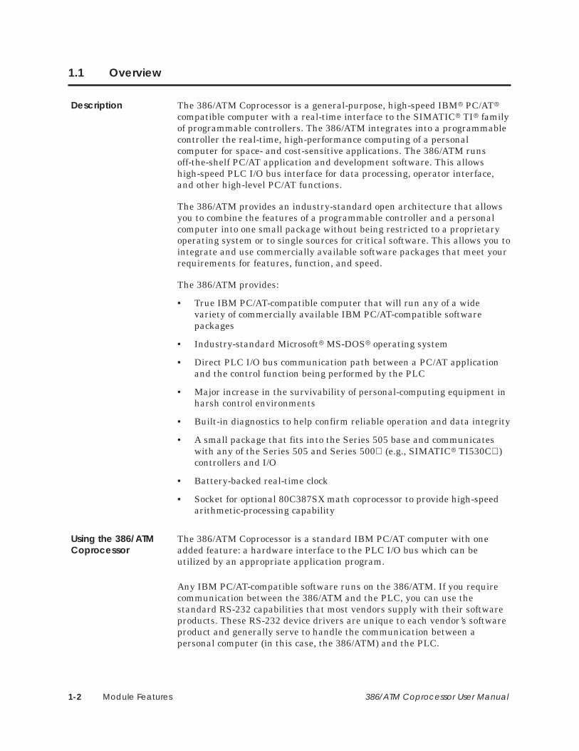
The 386/ATM Coprocessor is a general-purpose, high-speed IBM� PC/AT�compatible computer with a real-time interface to the SIMATIC� TI� familyof programmable controllers. The 386/ATM integrates into a programmablecontroller the real-time, high-performance computing of a personalcomputer for space- and cost-sensitive applications. The 386/ATM runsoff-the-shelf PC/AT application and development software. This allowshigh-speed PLC I/O bus interface for data processing, operator interface,and other high-level PC/AT functions.
The 386/ATM provides an industry-standard open architecture that allowsyou to combine the features of a programmable controller and a personalcomputer into one small package without being restricted to a proprietaryoperating system or to single sources for critical software. This allows you tointegrate and use commercially available software packages that meet yourrequirements for features, function, and speed.
The 386/ATM provides:
• True IBM PC/AT-compatible computer that will run any of a widevariety of commercially available IBM PC/AT-compatible softwarepackages
• Industry-standard Microsoft� MS-DOS� operating system
• Direct PLC I/O bus communication path between a PC/AT applicationand the control function being performed by the PLC
• Major increase in the survivability of personal-computing equipment inharsh control environments
• Built-in diagnostics to help confirm reliable operation and data integrity
• A small package that fits into the Series 505 base and communicateswith any of the Series 505 and Series 500 (e.g., SIMATIC� TI530C )controllers and I/O
• Battery-backed real-time clock
• Socket for optional 80C387SX math coprocessor to provide high-speedarithmetic-processing capability
The 386/ATM Coprocessor is a standard IBM PC/AT computer with oneadded feature: a hardware interface to the PLC I/O bus which can beutilized by an appropriate application program.
Any IBM PC/AT-compatible software runs on the 386/ATM. If you requirecommunication between the 386/ATM and the PLC, you can use thestandard RS-232 capabilities that most vendors supply with their softwareproducts. These RS-232 device drivers are unique to each vendor’s softwareproduct and generally serve to handle the communication between apersonal computer (in this case, the 386/ATM) and the PLC.
Description
Using the 386/ATMCoprocessor
Module Features 1-3386/ATM Coprocessor User Manual
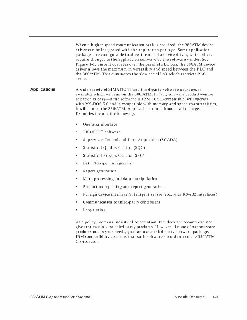
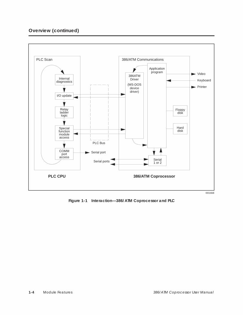
When a higher speed communication path is required, the 386ATM devicedriver can be integrated with the application package. Some applicationpackages are configurable to allow the use of a device driver, while othersrequire changes to the application software by the software vendor. SeeFigure 1-1. Since it operates over the parallel PLC bus, the 386ATM devicedriver allows the maximum in versatility and speed between the PLC andthe 386/ATM. This eliminates the slow serial link which restricts PLCaccess.
A wide variety of SIMATIC TI and third-party software packages isavailable which will run on the 386/ATM. In fact, software product/vendorselection is easy—if the software is IBM PC/AT-compatible, will operatewith MS-DOS 5.0 and is compatible with memory and speed characteristics,it will run on the 386/ATM. Applications range from small to large.Examples include the following.
• Operator interface
• TISOFT2 software
• Supervisor Control and Data Acquisition (SCADA)
• Statistical Quality Control (SQC)
• Statistical Process Control (SPC)
• Batch/Recipe management
• Report generation
• Math processing and data manipulation
• Production reporting and report generation
• Foreign device interface (intelligent sensor, etc., with RS-232 interfaces)
• Communication to third-party controllers
• Loop tuning
As a policy, Siemens Industrial Automation, Inc. does not recommend norgive testimonials for third-party products. However, if none of our softwareproducts meets your needs, you can use a third-party software package.IBM compatibility confirms that such software should run on the 386/ATMCoprocessor.
Applications
Module Features1-4 386/ATM Coprocessor User Manual
Overview (continued)
Internaldiagnostics
I/O update
Relayladderlogic
Specialfunctionmoduleaccess
COMMport
access
PLC CPU 386/ATM Coprocessor
Serial1 or 2
Floppydisk
Harddisk
Video
Keyboard
Printer
Serial port
PLC Bus
I001668
PLC Scan
386ATMDriver
(MS-DOSdevicedriver)
Applicationprogram
Serial ports
386/ATM Communications
Figure 1-1 Interaction—386/ATM Coprocessor and PLC

Module Features 1-5386/ATM Coprocessor User Manual
1.2 Features
Three versions of the 386/ATM module are available. See Figure 1-2 for thestandard configuration.
• Industrially hardened IBM PC/AT-compatible computer:
Intel� 80C386SX CPU16 MHz, zero wait-state analogSocket for optional 80C387SX math coprocessor
Microsoft MS-DOS 5.0 with QBasic (QuickBASIC)
DRAM Memory: 2M byte (505-ATM–0220) . . . . . 4M byte (505-ATM–0440)4M byte (505-ATM–4120)
Diskette drive: 3-1/2″ 720K byte/1.44M byte. . . . . . .
Hard disk drive: 20M byte (505-ATM–0220) . . . . . 40M byte (505-ATM–0440)120 M byte (505-ATM–4120)
• Triple-wide Series 505 module
• Direct PLC I/O bus interface to PLC
• 2 serial ports, 110 – 57600 baud; (non-standard driving voltage)
• Limited mouse support (see section 2.4)
• 1 Centronics�-style parallel port
• Keyboard port (for PC/AT-compatible keyboard)
• TISOFT2 PLC I/O bus communications for high-speed PLC interface
• 386ATM language-independent device driver (can be used by any PC/ATlanguage)
• No external power required
• Analog VGA monitor port (adapter cable from 9-pin to standard 15-pinVGA included)
• Built-in diagnostics

Module Features1-6 386/ATM Coprocessor User Manual
Features (continued)
I001669
386/ATMCOPROCESSOR
RESET
DISK
KYBD
VIDEO
COM 1
COM 2
PRN
Printer orParallel Device
Monitor
Keyboard
SerialDeviceRS-232
SerialDeviceRS-232
Figure 1-2 Typical Configuration

Module Features 1-7386/ATM Coprocessor User Manual
1.3 Standard Kit Part Lists
Includes:
Intel 80C386SX CPU
Socket for optional 80C387SX math coprocessor
DRAM Memory: 2M byteDiskette drive: 3-1/2″ 720K byte/1.44M byteHard disk drive: 20M byte
2 serial ports (110 – 57600 baud)
1 Centronics-style parallel port
Keyboard port (for PC/AT-compatible keyboard)
Analog VGA monitor port
386ATM video cable adapter
Microsoft MS-DOS 5.0 with QBasic and manual
Floppy disk containing the following software:
• 386ATM.DVR
• INSTALL.BAT
• AUTOEXEC.BAT
• CONFIG.SYS
• Example PCCOMM software (source code)
SIMATIC TI505 386/ATM Coprocessor User Manual
Same as PPX:505-ATM–0220, except:
DRAM Memory: 4M byte
Hard disk drive: 40M byte
Same as PPX:505-ATM–0220, except:
DRAM Memory: 4M byte
Hard disk drive: 120M byte
The following components can be ordered as spare parts.
• 386ATM video cable adapter (PPX:2587716–8034)
• MS-DOS 5.0, 3.5″ disks, and manual (PPX:2587716–8037)
• 386ATM Backplane Communications Driver (PPX:2587716–8038)
• 14″ VGA color monitor, industrial black (6AP1–705–0BG00)
PPX:505–ATM–0220
PPX:505–ATM–0440
PPX:505–ATM–4120
Spare Parts

Module Features1-8 386/ATM Coprocessor User Manual
• 101-key PC/AT keyboard, industrial black (6AC1–015–7FG)

Module Features 1-9386/ATM Coprocessor User Manual
1.4 Recommended Order of Tasks
Install the module
Install the system software
Log the module into the base (if applicable)
Program the module
I001671
Install MS-DOS 5.0
Figure 1-3 Lists of Tasks for Installing and Using the 386/ATM

Installing the Module 2-1386/ATM Coprocessor User Manual
Chapter 2
Installing the Module
2.1 Overview of Installation 2-2. . . . . . . . . . . . . . . . . . . . . . . . . . . . . . . . . . . . . . . . . . . . . . . . . . . . . . . . . Handling the Module 2-2. . . . . . . . . . . . . . . . . . . . . . . . . . . . . . . . . . . . . . . . . . . . . . . . . . . . . . . . . . . Visual Inspection 2-2. . . . . . . . . . . . . . . . . . . . . . . . . . . . . . . . . . . . . . . . . . . . . . . . . . . . . . . . . . . . . . . . Technical Assistance 2-2. . . . . . . . . . . . . . . . . . . . . . . . . . . . . . . . . . . . . . . . . . . . . . . . . . . . . . . . . . . . Flow of Tasks 2-3. . . . . . . . . . . . . . . . . . . . . . . . . . . . . . . . . . . . . . . . . . . . . . . . . . . . . . . . . . . . . . . . . . . .
2.2 Configuring the Module 2-4. . . . . . . . . . . . . . . . . . . . . . . . . . . . . . . . . . . . . . . . . . . . . . . . . . . . . . . . .
2.3 Inserting the Module into the Base 2-5. . . . . . . . . . . . . . . . . . . . . . . . . . . . . . . . . . . . . . . . . . . . . . . Inserting the Module 2-5. . . . . . . . . . . . . . . . . . . . . . . . . . . . . . . . . . . . . . . . . . . . . . . . . . . . . . . . . . . . Power Requirements 2-5. . . . . . . . . . . . . . . . . . . . . . . . . . . . . . . . . . . . . . . . . . . . . . . . . . . . . . . . . . . .
2.4 Connecting Peripherals 2-6. . . . . . . . . . . . . . . . . . . . . . . . . . . . . . . . . . . . . . . . . . . . . . . . . . . . . . . . . Monitor 2-6. . . . . . . . . . . . . . . . . . . . . . . . . . . . . . . . . . . . . . . . . . . . . . . . . . . . . . . . . . . . . . . . . . . . . . . . Keyboard 2-6. . . . . . . . . . . . . . . . . . . . . . . . . . . . . . . . . . . . . . . . . . . . . . . . . . . . . . . . . . . . . . . . . . . . . . Communications 2-6. . . . . . . . . . . . . . . . . . . . . . . . . . . . . . . . . . . . . . . . . . . . . . . . . . . . . . . . . . . . . . . Printer 2-6. . . . . . . . . . . . . . . . . . . . . . . . . . . . . . . . . . . . . . . . . . . . . . . . . . . . . . . . . . . . . . . . . . . . . . . . . .
Installing the Module2-2 386/ATM Coprocessor User Manual
2.1 Overview of Installation
Many integrated circuit (IC) devices are susceptible to damage by thedischarge of static electricity. Follow the suggestions listed below to reducethe probability of damage to these devices when you are handling acontroller, a base controller, or any of the I/O modules.
Both the module and the person handling the module should be at the sameground potential. To accomplish this, fulfill the following conditions.
• Transport the module in an anti-static container or antistatic material.
• Ensure that the work area has a conductive pad with a lead connectingthe work area to a common ground.
• Ground yourself by making contact with the conductive pad or bywearing a grounded wrist strap.
If there is any visible damage to the module, contact your vendor for areplacement.
If you need information that is not included in this manual, or if you haveproblems using the module, call your Siemens Industrial Automation, Inc.distributor or sales office. If you need assistance in contacting your U.S.distributor or sales office, call 1–800–964-4114.
Handling theModule
Visual Inspection
TechnicalAssistance
Installing the Module 2-3386/ATM Coprocessor User Manual
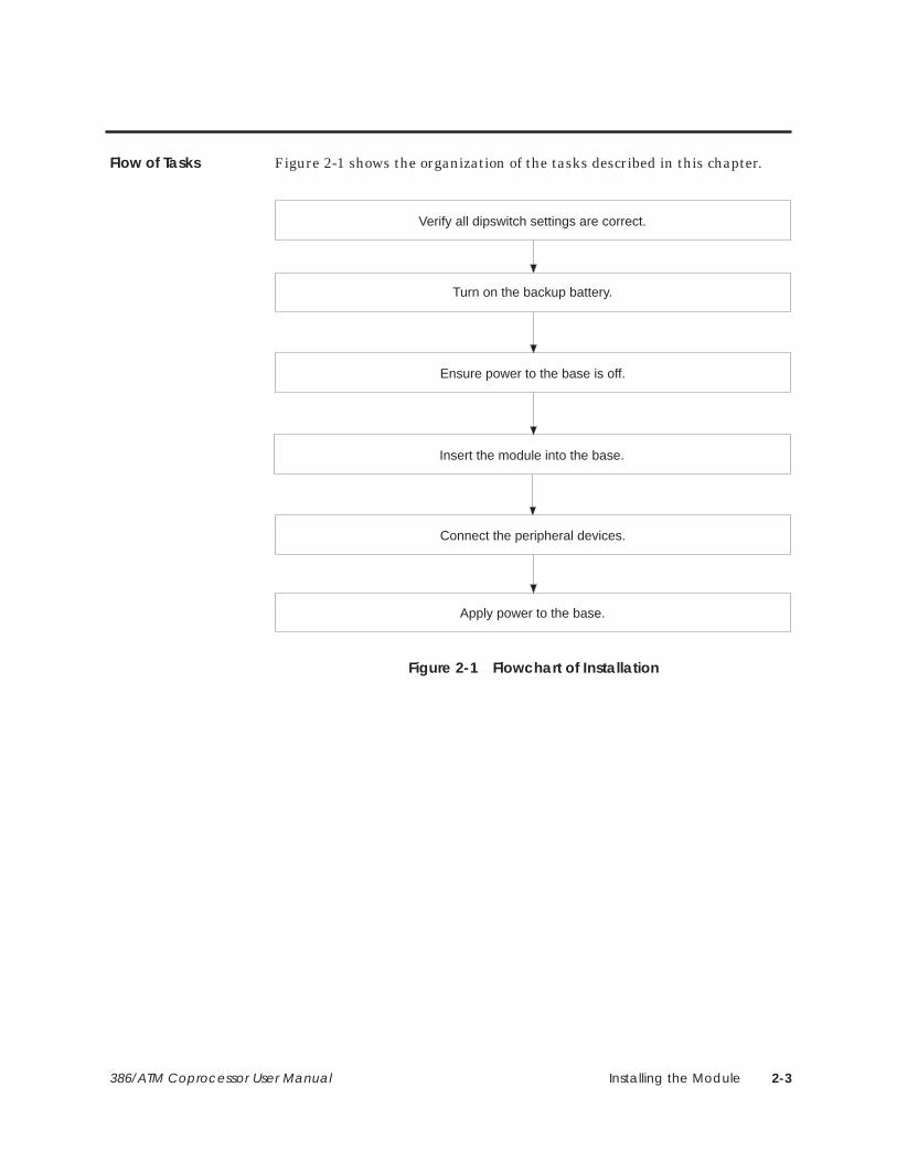
Figure 2-1 shows the organization of the tasks described in this chapter.
Verify all dipswitch settings are correct.
Turn on the backup battery.
Ensure power to the base is off.
Connect the peripheral devices.
Insert the module into the base.
Apply power to the base.
Figure 2-1 Flowchart of Installation
Flow of Tasks

Installing the Module2-4 386/ATM Coprocessor User Manual
2.2 Configuring the Module
Before you install the 386/ATM Coprocessor, turn on the backup battery,and verify dipswitch settings.
To accomplish these tasks, locate the dipswitches shown in Figure 2-2 andset them according to Figure 2-3.
I001700
Dipswitches387SX Socket
Figure 2-2 Location of Dipswitches
+ –
Battery
1 2 3 4 5 6 7 8
Internal use only;Must be On
I001674
Internal use only;Must be On
Con
nect
or
Depress on Depress on
Switches 1 and 4 are for Siemens proprietary use; they mustbe On. Switches 2, 3, 5, 6, and 7 are not used; set to Off.
Figure 2-3 Dipswitch

Installing the Module 2-5386/ATM Coprocessor User Manual
2.3 Inserting the Module into the Base
To minimize potential shock, turn off power to the I/O base and toany modules installed in the base before you insert or remove amodule or install a terminal block. Failure to do so may result inpotential injury to personnel or damage to equipment.
Refer to the Safety Considerations sheet (part # 2588015–0002)included with your module for a complete list of safety guidelinesand recommendations.
This is a triple-wide module. Insert it into any available I/O slot on anySeries 505 base. Insert the module as shown in Figure 2-4. Note theminimum torque required to ground the module.
Minimum torque: 2.6 in-lb (0.3N-m)
Maximum torque: 4.12 in-lb (0.6N-m)
Backplane connectors
A000329
Figure 2-4 Inserting the Module into the Base
This module requires 11.0 W of +5 V and 0.2 W of –5 V power from theSeries 505 base. No additional power is required.
WARNING!
Inserting theModule
PowerRequirements
Installing the Module2-6 386/ATM Coprocessor User Manual
2.4 Connecting Peripherals
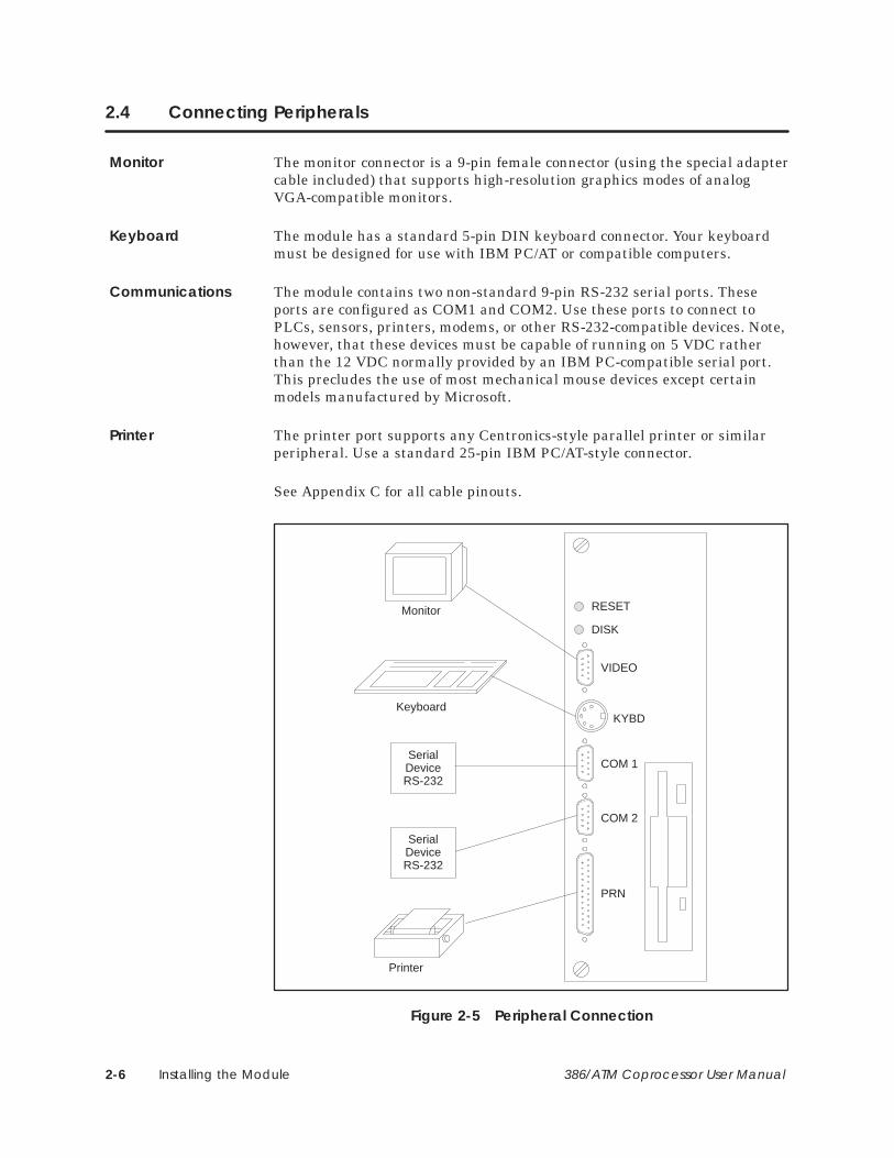
The monitor connector is a 9-pin female connector (using the special adaptercable included) that supports high-resolution graphics modes of analogVGA-compatible monitors.
The module has a standard 5-pin DIN keyboard connector. Your keyboardmust be designed for use with IBM PC/AT or compatible computers.
The module contains two non-standard 9-pin RS-232 serial ports. Theseports are configured as COM1 and COM2. Use these ports to connect toPLCs, sensors, printers, modems, or other RS-232-compatible devices. Note,however, that these devices must be capable of running on 5 VDC ratherthan the 12 VDC normally provided by an IBM PC-compatible serial port.This precludes the use of most mechanical mouse devices except certainmodels manufactured by Microsoft.
The printer port supports any Centronics-style parallel printer or similarperipheral. Use a standard 25-pin IBM PC/AT-style connector.
See Appendix C for all cable pinouts.
RESET
DISK
KYBD
VIDEO
COM 1
COM 2
PRN
Printer
Monitor
Keyboard
SerialDeviceRS-232
SerialDeviceRS-232
Figure 2-5 Peripheral Connection
Monitor
Keyboard
Communications
Printer
Loading System Software 3-1386/ATM Coprocessor User Manual
Chapter 3
Loading System Software
3.1 Overview 3-2. . . . . . . . . . . . . . . . . . . . . . . . . . . . . . . . . . . . . . . . . . . . . . . . . . . . . . . . . . . . . . . . . . . . . . . Potential for Errors During Diskette Access 3-3. . . . . . . . . . . . . . . . . . . . . . . . . . . . . . . . . . . . . . . .
3.2 Setting System Parameters 3-4. . . . . . . . . . . . . . . . . . . . . . . . . . . . . . . . . . . . . . . . . . . . . . . . . . . . . .
3.3 Preparing the Hard Disk and Loading MS-DOS 3-5. . . . . . . . . . . . . . . . . . . . . . . . . . . . . . . . . . . . Booting the Module from the Diskette 3-5. . . . . . . . . . . . . . . . . . . . . . . . . . . . . . . . . . . . . . . . . . . .
3.4 Installing System Software 3-6. . . . . . . . . . . . . . . . . . . . . . . . . . . . . . . . . . . . . . . . . . . . . . . . . . . . . . . Copying Software to the Hard Disk 3-6. . . . . . . . . . . . . . . . . . . . . . . . . . . . . . . . . . . . . . . . . . . . . . . Typical ATM Driver Files 3-7. . . . . . . . . . . . . . . . . . . . . . . . . . . . . . . . . . . . . . . . . . . . . . . . . . . . . . . . . . Installing Sample Programs 3-8. . . . . . . . . . . . . . . . . . . . . . . . . . . . . . . . . . . . . . . . . . . . . . . . . . . . . . Loading System Device Drivers 3-8. . . . . . . . . . . . . . . . . . . . . . . . . . . . . . . . . . . . . . . . . . . . . . . . . .
3.5 What Next? 3-9. . . . . . . . . . . . . . . . . . . . . . . . . . . . . . . . . . . . . . . . . . . . . . . . . . . . . . . . . . . . . . . . . . . . . Running the 386/ATM with Third-party Device Drivers and Memory Managers 3-9. . . . . .
Loading System Software3-2 386/ATM Coprocessor User Manual
3.1 Overview
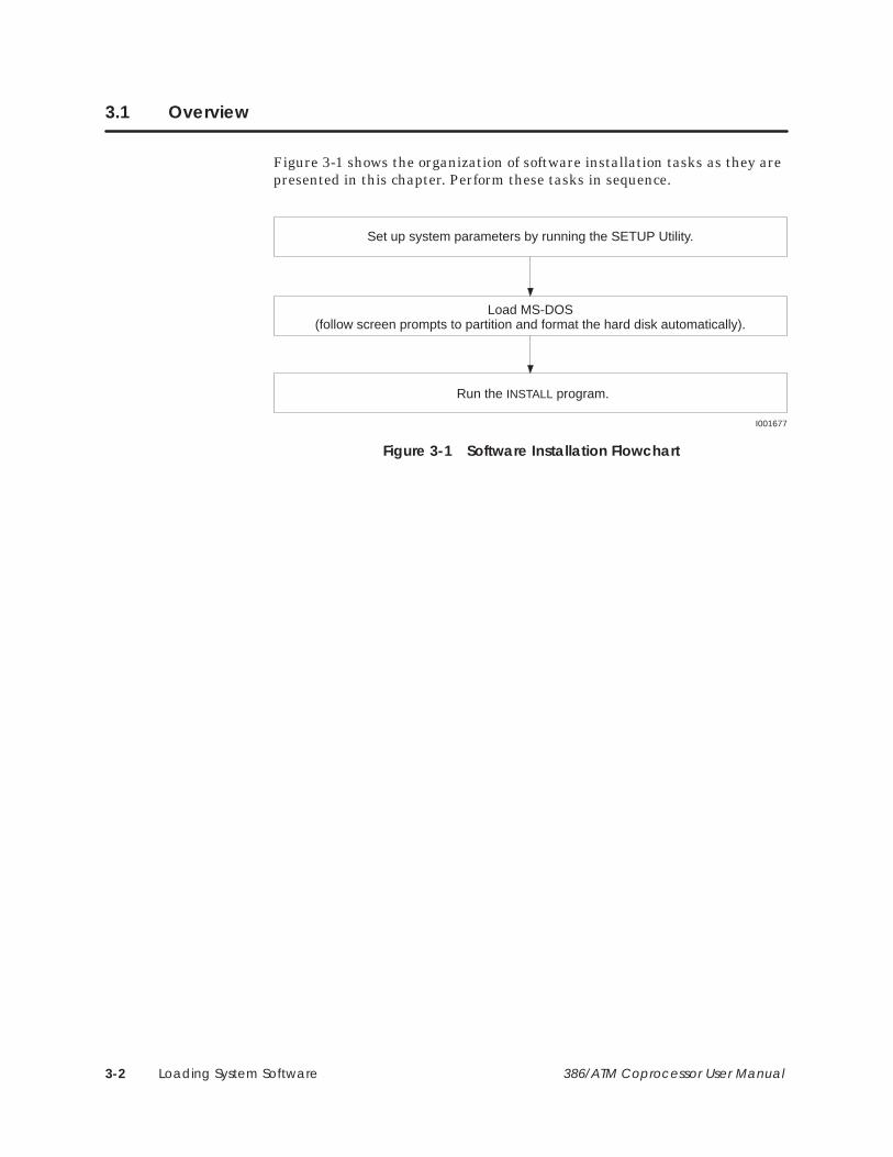
Figure 3-1 shows the organization of software installation tasks as they arepresented in this chapter. Perform these tasks in sequence.
Set up system parameters by running the SETUP Utility.
Load MS-DOS(follow screen prompts to partition and format the hard disk automatically).
Run the INSTALL program.
I001677
Figure 3-1 Software Installation Flowchart

Loading System Software 3-3386/ATM Coprocessor User Manual
NOTE: To extend battery life, the 386/ATM Coprocessor is shipped from thefactory with the battery switch in the OFF position. Since the systemparameters are stored in battery-backed CMOS RAM, you must run theSETUP Utility during initial module installation or after a battery failure.
During periods of high conducted or radiated electrical noise conditions,diskette access may cause seek and/or read/write errors. These errors do notaffect the operation of other parts of either the 386/ATM or theprogrammable controller system.
It is recommended that you start up with the diskette and then switch tothe hard drive for operation. If you experience a seek or read/write errorduring a diskette access, please try the operation a second time. If theproblem continues, wait for quiescent periods before performing disketteoperations.
As in any electrical installation, the potential for live circuits maybe present at the PLC and/or adjacent devices when the ultimateprotective enclosure is opened for routine service, maintenance orprogramming. Accidental contact with live circuits may result inpersonal injury or damage to equipment. Installation, maintenanceand programming must only be performed by qualified andauthorized personnel familiar with recognized electrical practicesand procedures in working with high voltage.
Potential for ErrorsDuring DisketteAccess
WARNING!

Loading System Software3-4 386/ATM Coprocessor User Manual
3.2 Setting System Parameters
After initial installation, after a battery failure, or if the battery is disabled,you must run the SETUP Utility to set the real-time clock date and time, toidentify the number and type of hard disks and to identify the number andsize of floppy diskettes. Setup parameters are saved in battery-backedCMOS RAM. Follow the steps shown in Figure 3-2.
1. Press the Reset Button if thisis a first-time installation1
OR
Alt DelCntl
Extended BIOSMenu
4. Select: Setup
Extended BIOSSetup Menu
5. Use up/down arrowsto select parameters,then press F5 or F6to change values.Selections are:
F106. To save the configuration, press
7. To acknowledge that the changes have beensaved in CMOS memory, press
Diskette Drive 0: 1.44mb, 3-1/2”Fixed Disk 0: –0220 (20M unit): 2Fixed Disk 0: –0440 (40M unit): 17Fixed Disk 0: –4120 (120M unit): 41
8. Press to exit.
F2
Esc
1
if you are in DOS environment.
2. Hold spacebar until you receive “39 keyboard error”
Esc
I001678
Enter
Enter
3.
Figure 3-2 System Configuration
1You can speed up the boot process by pressing Esc at the prompt to skip the RAMdiagnostics. Then, if you want to access the Setup utility, hold down the spacebar as describedin step 2 above and continue when prompted by pressing F2 to access the Extended BIOSMenu and the Setup Utility option.
Loading System Software 3-5386/ATM Coprocessor User Manual
3.3 Preparing the Hard Disk and Loading MS-DOS
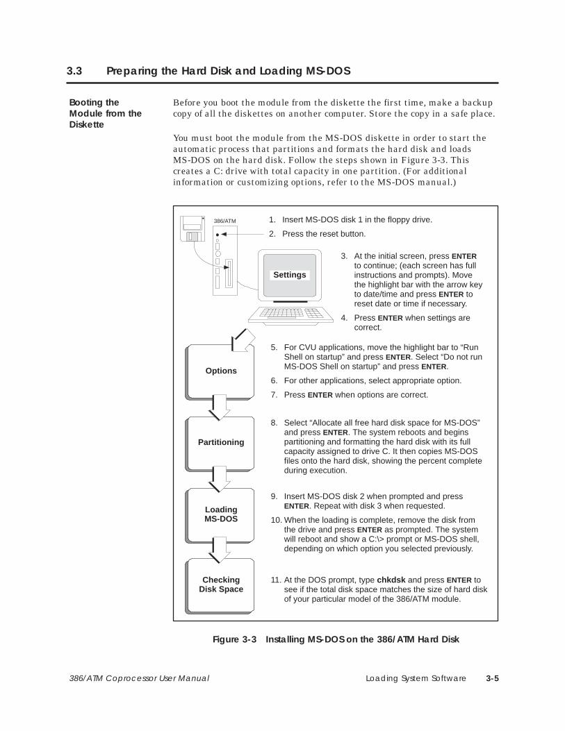
Before you boot the module from the diskette the first time, make a backupcopy of all the diskettes on another computer. Store the copy in a safe place.
You must boot the module from the MS-DOS diskette in order to start theautomatic process that partitions and formats the hard disk and loadsMS-DOS on the hard disk. Follow the steps shown in Figure 3-3. Thiscreates a C: drive with total capacity in one partition. (For additionalinformation or customizing options, refer to the MS-DOS manual.)
1. Insert MS-DOS disk 1 in the floppy drive.
2. Press the reset button.
Options
Partitioning
LoadingMS-DOS
CheckingDisk Space
3. At the initial screen, press ENTERto continue; (each screen has fullinstructions and prompts). Movethe highlight bar with the arrow keyto date/time and press ENTER toreset date or time if necessary.
4. Press ENTER when settings arecorrect.
Settings
5. For CVU applications, move the highlight bar to “RunShell on startup” and press ENTER. Select “Do not runMS-DOS Shell on startup” and press ENTER.
6. For other applications, select appropriate option.
7. Press ENTER when options are correct.
8. Select “Allocate all free hard disk space for MS-DOS”and press ENTER. The system reboots and beginspartitioning and formatting the hard disk with its fullcapacity assigned to drive C. It then copies MS-DOSfiles onto the hard disk, showing the percent completeduring execution.
9. Insert MS-DOS disk 2 when prompted and pressENTER. Repeat with disk 3 when requested.
10. When the loading is complete, remove the disk fromthe drive and press ENTER as prompted. The systemwill reboot and show a C:\> prompt or MS-DOS shell,depending on which option you selected previously.
11. At the DOS prompt, type chkdsk and press ENTER tosee if the total disk space matches the size of hard diskof your particular model of the 386/ATM module.
386/ATM
Figure 3-3 Installing MS-DOS on the 386/ATM Hard Disk
Booting theModule from theDiskette
Loading System Software3-6 386/ATM Coprocessor User Manual
3.4 Installing System Software
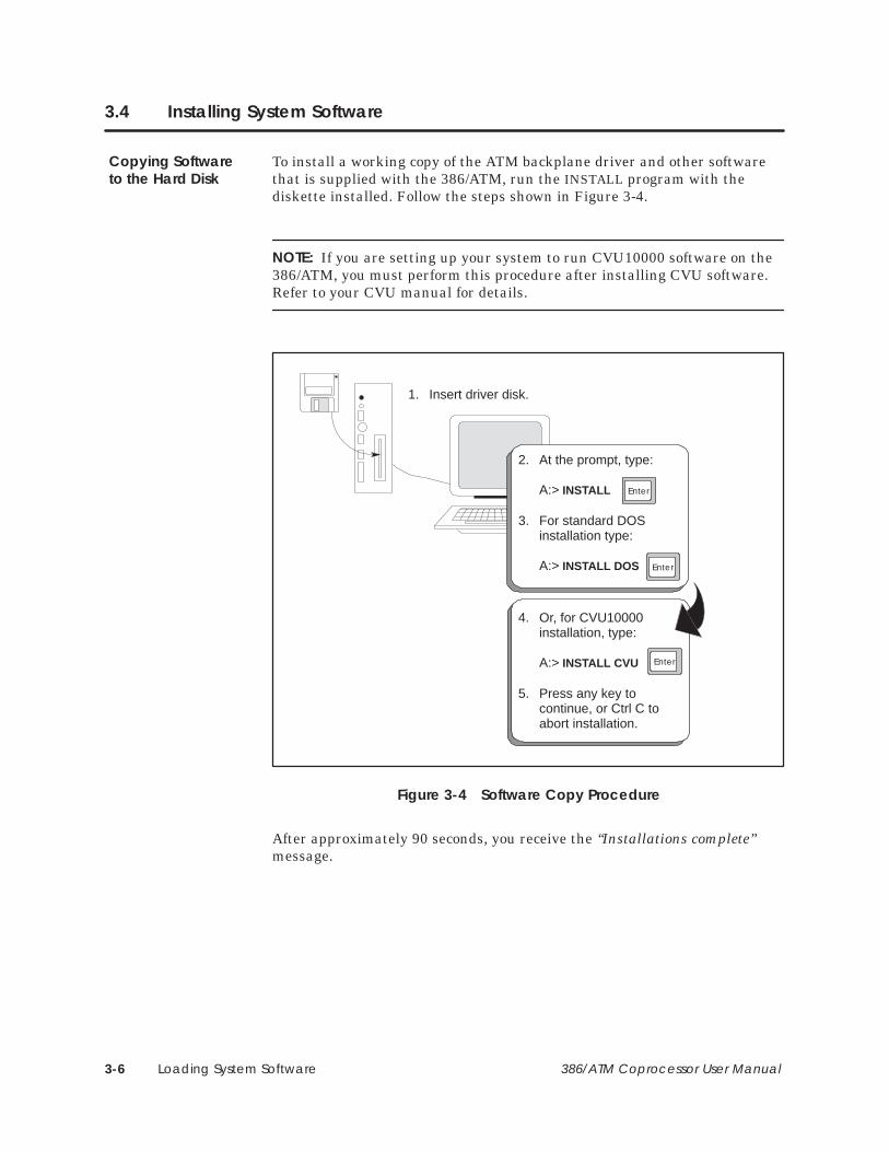
To install a working copy of the ATM backplane driver and other softwarethat is supplied with the 386/ATM, run the INSTALL program with thediskette installed. Follow the steps shown in Figure 3-4.
NOTE: If you are setting up your system to run CVU10000 software on the386/ATM, you must perform this procedure after installing CVU software.Refer to your CVU manual for details.
Enter
1. Insert driver disk.
2. At the prompt, type:
A:> INSTALL
3. For standard DOSinstallation type:
A:> INSTALL DOS
Enter
4. Or, for CVU10000installation, type:
A:> INSTALL CVU
5. Press any key tocontinue, or Ctrl C toabort installation.
Enter
Figure 3-4 Software Copy Procedure
After approximately 90 seconds, you receive the “Installations complete”message.
Copying Softwareto the Hard Disk

Loading System Software 3-7386/ATM Coprocessor User Manual
After the automatic installation of the ATM driver is complete, yourAUTOEXEC.BAT and CONFIG.SYS files will look like the following.
AUTOEXEC.BAT file for standard DOS installation.
@ECHO OFFPROMPT $P$GPATH=C:\;C:\DOS;C:\TI
CONFIG.SYS file for standard DOS installation.
FILES=30BUFFERS=20SHELL=C:\DOS\COMMAND.COM C:\DOS\ /PDEVICE=C:\DOS\HIMEM.SYSDOS=HIGH,umbDEVICE=C:\DOS\EMM386.EXE X=C800–C900 NOEMSDEVICEHIGH=C:\386ATM.EXE
AUTOEXEC.BAT file for CVU10000 installation.
@ECHO OFFPROMPT $P$GPATH=C:\CVU10;C:\;C:\DOS;C:\TICVU10000.BAT
CONFIG.SYS file for CVU10000 installation.
FILES=30BUFFERS=20SHELL=C:\DOS\COMMAND.COM C:\DOS\ /PDEVICE=C:\DOS\HIMEM.SYSDOS=HIGH,umbDEVICE=C:\DOS\EMM386.EXE X=C800–C900 NOEMSDEVICEHIGH=C:\386ATM.EXEDEVICEHIGH=C:\CVU10\PRINTER.DEV
Typical ATM DriverFiles
Loading System Software3-8 386/ATM Coprocessor User Manual
Installing System Software (continued)
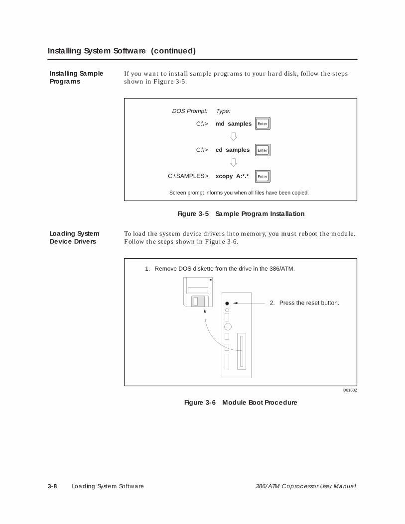
If you want to install sample programs to your hard disk, follow the stepsshown in Figure 3-5.
C:\>
C:\>
md samples
DOS Prompt: Type:
cd samples
Enter
Enter
C:\SAMPLES> xcopy A:*.* Enter
Screen prompt informs you when all files have been copied.
Figure 3-5 Sample Program Installation
To load the system device drivers into memory, you must reboot the module.Follow the steps shown in Figure 3-6.
1. Remove DOS diskette from the drive in the 386/ATM.
2. Press the reset button.
I001682
Figure 3-6 Module Boot Procedure
Installing SamplePrograms
Loading SystemDevice Drivers
Loading System Software 3-9386/ATM Coprocessor User Manual
3.5 What Next?
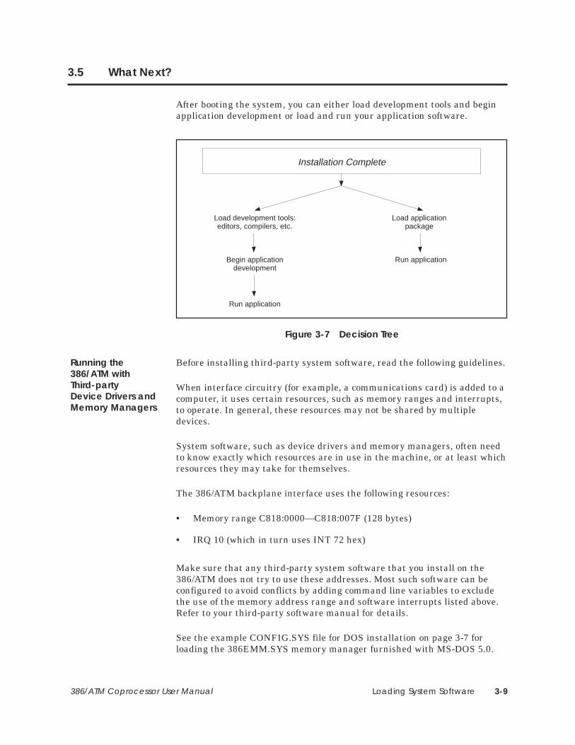
After booting the system, you can either load development tools and beginapplication development or load and run your application software.
Load development tools:editors, compilers, etc.
Begin applicationdevelopment
Run application
Load applicationpackage
Run application
Installation Complete
Figure 3-7 Decision Tree
Before installing third-party system software, read the following guidelines.
When interface circuitry (for example, a communications card) is added to acomputer, it uses certain resources, such as memory ranges and interrupts,to operate. In general, these resources may not be shared by multipledevices.
System software, such as device drivers and memory managers, often needto know exactly which resources are in use in the machine, or at least whichresources they may take for themselves.
The 386/ATM backplane interface uses the following resources:
• Memory range C818:0000—C818:007F (128 bytes)
• IRQ 10 (which in turn uses INT 72 hex)
Make sure that any third-party system software that you install on the386/ATM does not try to use these addresses. Most such software can beconfigured to avoid conflicts by adding command line variables to excludethe use of the memory address range and software interrupts listed above.Refer to your third-party software manual for details.
See the example CONFIG.SYS file for DOS installation on page 3-7 forloading the 386EMM.SYS memory manager furnished with MS-DOS 5.0.
Running the386/ATM withThird-partyDevice Drivers andMemory Managers

Running TISOFT on the 386/ATM 4-1386/ATM Coprocessor User Manual
Chapter 4
Running TISOFT on the 386/ATM
4.1 Logging the 386/ATM into the PLC I/O Configuration Table 4-2. . . . . . . . . . . . . . . . . . . . . . . . Overview 4-2. . . . . . . . . . . . . . . . . . . . . . . . . . . . . . . . . . . . . . . . . . . . . . . . . . . . . . . . . . . . . . . . . . . . . . . Loading TISOFT2 4-2. . . . . . . . . . . . . . . . . . . . . . . . . . . . . . . . . . . . . . . . . . . . . . . . . . . . . . . . . . . . . . . . Verifying 386ATM.EXE in your Root Directory 4-2. . . . . . . . . . . . . . . . . . . . . . . . . . . . . . . . . . . . . . . Communicating with the PLC 4-3. . . . . . . . . . . . . . . . . . . . . . . . . . . . . . . . . . . . . . . . . . . . . . . . . . . Running TISOFT2 4-3. . . . . . . . . . . . . . . . . . . . . . . . . . . . . . . . . . . . . . . . . . . . . . . . . . . . . . . . . . . . . . . . Selecting the I/O Definition Chart 4-4. . . . . . . . . . . . . . . . . . . . . . . . . . . . . . . . . . . . . . . . . . . . . . . . Viewing the I/O Configuration Chart 4-4. . . . . . . . . . . . . . . . . . . . . . . . . . . . . . . . . . . . . . . . . . . . .

Running TISOFT on the 386/ATM4-2 386/ATM Coprocessor User Manual
4.1 Logging the 386/ATM into the PLC I/O Configuration Table
Log the 386/ATM into the PLC I/O configuration memory for maximumcommunication speed with the PLC over the I/O bus. The procedurerequired for logging modules varies with the type of PLC. (See Figure 4-1.)
• SIMATIC TI545/TI555 and TI560/TI565 PLCs require you to configurethe I/O manually.
• All other Series 505/Series 500 PLCs automatically configure the I/O.
Type of PLC?
TI545/TI555TI560/TI565
Use TISOFT toconfigure I/O table
All otherSeries 505/500 PLCs
386/ATM I/O configurationperformed automatically
Figure 4-1 I/O Configuration Decision Tree
NOTE: The 386/ATM does not have to be logged into the I/O configurationtable to run TISOFT2. Logging the module into the configuration tableimproves TISOFT2 communication performance.
Refer to the TISOFT2 manual for specific instructions on loading andrunning TISOFT2 software.
The config.sys file must include an instruction to load 386ATM.EXE duringthe module’s boot procedure. The INSTALL batch file included as part of theinstallation procedure does this automatically for both the standard DOSand CUV10000 options. (See page 3-7 for the listing of files created by theINSTALL procedure.)
Overview
Loading TISOFT2
Verifying386ATM.EXE in yourRoot Directory

Running TISOFT on the 386/ATM 4-3386/ATM Coprocessor User Manual
You can communicate with the PLC via the I/O bus (Figure 4-2) or via theserial ports (Figure 4-3). Communicating via the serial port requires a cableand does not realize the improved speed offered by the I/O bus.
To run TISOFT2, enter the command appropriate to the PLC and version ofTISOFT2 you are using.
I001685
PLC 386/ATM
PLC I/O Bus
Run TISOFT with the CVU option.
Example: TI505 CVU
TISOFTI/O Bus
Figure 4-2 Running TISOFT2 via I/O Bus
I001686
PLC
COM 1
COM 2
386/ATM
PLC Programming Port
TISOFT
COM1 or COM2 to PLC programming port:
Run TISOFT with no port option for port 1,or with P2 for port 2.
Example: TI505 P2
orCable part # 2601094–8001
Figure 4-3 Running TISOFT2 via Serial Port
Communicatingwith the PLC
Running TISOFT2
Running TISOFT on the 386/ATM4-4 386/ATM Coprocessor User Manual
Logging the 386/ATM into the PLC I/O Configuration Table (continued)
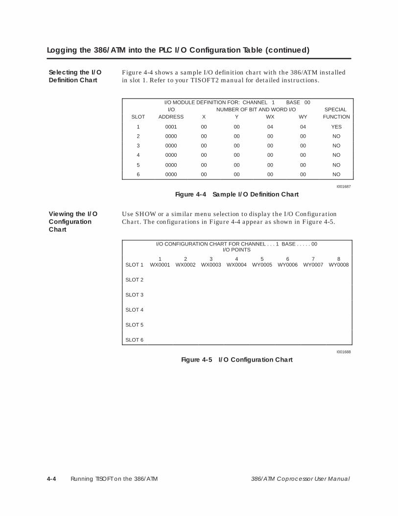
Figure 4-4 shows a sample I/O definition chart with the 386/ATM installedin slot 1. Refer to your TISOFT2 manual for detailed instructions.
I/O MODULE DEFINITION FOR: CHANNEL 1 BASE 00I/O NUMBER OF BIT AND WORD I/O SPECIAL
SLOT ADDRESS X Y WX WY FUNCTION
1 0001 00 00 04 04 YES
2 0000 00 00 00 00 NO
3 0000 00 00 00 00 NO
4 0000 00 00 00 00 NO
5 0000 00 00 00 00 NO
6 0000 00 00 00 00 NO
I001687
Figure 4-4 Sample I/O Definition Chart
Use SHOW or a similar menu selection to display the I/O ConfigurationChart. The configurations in Figure 4-4 appear as shown in Figure 4-5.
I/O CONFIGURATION CHART FOR CHANNEL . . . 1 BASE . . . . . 00I/O POINTS
SLOT 11
WX00012
WX00023
WX00034
WX00045
WY00056
WY00067
WY00078
WY0008
SLOT 2
SLOT 3
SLOT 4
SLOT 5
SLOT 6
I001688
Figure 4-5 I/O Configuration Chart
Selecting the I/ODefinition Chart
Viewing the I/OConfigurationChart

PLC Communications 5-1386/ATM Coprocessor User Manual
Chapter 5
PLC Communications
5.1 Overview 5-2. . . . . . . . . . . . . . . . . . . . . . . . . . . . . . . . . . . . . . . . . . . . . . . . . . . . . . . . . . . . . . . . . . . . . . . Communicating with the PLC 5-2. . . . . . . . . . . . . . . . . . . . . . . . . . . . . . . . . . . . . . . . . . . . . . . . . . . Verifying the CONFIG.SYS File in your Root Directory 5-2. . . . . . . . . . . . . . . . . . . . . . . . . . . . . . . Using PCCOMM 5-3. . . . . . . . . . . . . . . . . . . . . . . . . . . . . . . . . . . . . . . . . . . . . . . . . . . . . . . . . . . . . . . . Application Program I/O Bus Communication 5-3. . . . . . . . . . . . . . . . . . . . . . . . . . . . . . . . . . . .
5.2 Communicating during PLC Scan: I/O Cycle 5-4. . . . . . . . . . . . . . . . . . . . . . . . . . . . . . . . . . . . . Accessing I/O Points 5-4. . . . . . . . . . . . . . . . . . . . . . . . . . . . . . . . . . . . . . . . . . . . . . . . . . . . . . . . . . . . Command Syntax: IOREAD 5-5. . . . . . . . . . . . . . . . . . . . . . . . . . . . . . . . . . . . . . . . . . . . . . . . . . . . . . Response Syntax: IOREAD 5-5. . . . . . . . . . . . . . . . . . . . . . . . . . . . . . . . . . . . . . . . . . . . . . . . . . . . . . . Command Syntax: IOWRITE 5-6. . . . . . . . . . . . . . . . . . . . . . . . . . . . . . . . . . . . . . . . . . . . . . . . . . . . . Response Syntax: IOWRITE 5-6. . . . . . . . . . . . . . . . . . . . . . . . . . . . . . . . . . . . . . . . . . . . . . . . . . . . . . .
5.3 Communicating with the PLC Scan: Special Function Cycle 5-7. . . . . . . . . . . . . . . . . . . . . . . Description 5-7. . . . . . . . . . . . . . . . . . . . . . . . . . . . . . . . . . . . . . . . . . . . . . . . . . . . . . . . . . . . . . . . . . . . . Command Syntax: PCREAD 5-8. . . . . . . . . . . . . . . . . . . . . . . . . . . . . . . . . . . . . . . . . . . . . . . . . . . . . Response Syntax: PCREAD 5-8. . . . . . . . . . . . . . . . . . . . . . . . . . . . . . . . . . . . . . . . . . . . . . . . . . . . . . . Command Syntax: PCWRITE 5-9. . . . . . . . . . . . . . . . . . . . . . . . . . . . . . . . . . . . . . . . . . . . . . . . . . . . . Response Syntax: PCWRITE 5-9. . . . . . . . . . . . . . . . . . . . . . . . . . . . . . . . . . . . . . . . . . . . . . . . . . . . . . Executing Commands from a File 5-9. . . . . . . . . . . . . . . . . . . . . . . . . . . . . . . . . . . . . . . . . . . . . . . . Notes Concerning Writing to Memory Locations 5-10. . . . . . . . . . . . . . . . . . . . . . . . . . . . . . . . . .
5.4 Communicating with the PLC: COMM Port Cycle 5-11. . . . . . . . . . . . . . . . . . . . . . . . . . . . . . . . . Serial Port to PLC 5-11. . . . . . . . . . . . . . . . . . . . . . . . . . . . . . . . . . . . . . . . . . . . . . . . . . . . . . . . . . . . . . . . RS-232 Com1 and Com2 5-11. . . . . . . . . . . . . . . . . . . . . . . . . . . . . . . . . . . . . . . . . . . . . . . . . . . . . . . .
PLC Communications5-2 386/ATM Coprocessor User Manual
5.1 Overview
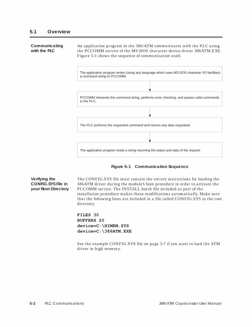
An application program in the 386/ATM communicates with the PLC usingthe PCCOMM service of the MS-DOS character device driver 386ATM.EXE.Figure 5-1 shows the sequence of communication used.
The application program writes (using any language which uses MS-DOS character I/O facilities)a command string to PCCOMM.
PCCOMM interprets the command string, performs error checking, and passes valid commandsto the PLC.
The PLC performs the requested command and returns any data requested.
The application program reads a string returning the status and data of the request.
Figure 5-1 Communication Sequence
The CONFIG.SYS file must contain the correct instructions for loading the386ATM driver during the module’s boot procedure in order to activate thePCCOMM service. The INSTALL batch file included as part of theinstallation procedure makes these modifications automatically. Make surethat the following lines are included in a file called CONFIG.SYS in the rootdirectory.
FILES 30BUFFERS 20device=C:\HIMEM.SYSdevice=C:\386ATM.EXE
See the example CONFIG.SYS file on page 3-7 if you want to load the ATMdriver in high memory.
Communicatingwith the PLC
Verifying theCONFIG.SYS File inyour Root Directory
PLC Communications 5-3386/ATM Coprocessor User Manual
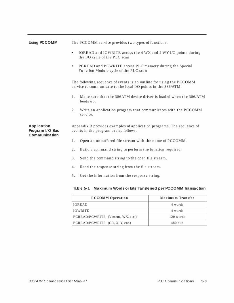
The PCCOMM service provides two types of functions:
• IOREAD and IOWRITE access the 4 WX and 4 WY I/O points duringthe I/O cycle of the PLC scan
• PCREAD and PCWRITE access PLC memory during the SpecialFunction Module cycle of the PLC scan
The following sequence of events is an outline for using the PCCOMMservice to communicate to the local I/O points in the 386/ATM.
1. Make sure that the 386ATM device driver is loaded when the 386/ATMboots up.
2. Write an application program that communicates with the PCCOMMservice.
Appendix B provides examples of application programs. The sequence ofevents in the program are as follows.
1. Open an unbuffered file stream with the name of PCCOMM.
2. Build a command string to perform the function required.
3. Send the command string to the open file stream.
4. Read the response string from the file stream.
5. Get the information from the response string.
Table 5-1 Maximum Words or Bits Transferred per PCCOMM Transaction
PCCOMM Operation Maximum Transfer
IOREAD 4 words
IOWRITE 4 words
PCREAD/PCWRITE (V-mem, WX, etc.) 120 words
PCREAD/PCWRITE (CR, X, Y, etc.) 480 bits
Using PCCOMM
ApplicationProgram I/O BusCommunication
PLC Communications5-4 386/ATM Coprocessor User Manual
5.2 Communicating during PLC Scan: I/O Cycle
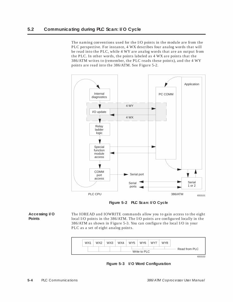
The naming conventions used for the I/O points in the module are from thePLC perspective. For instance, 4 WX describes four analog words that willbe read into the PLC, while 4 WY are analog words that are an output fromthe PLC. In other words, the points labeled as 4 WX are points that the386/ATM writes to (remember, the PLC reads these points), and the 4 WYpoints are read into the 386/ATM. See Figure 5-2.
Internaldiagnostics
Relayladderlogic
Specialfunctionmoduleaccess
COMMport
access
PLC CPU
Application
386/ATM
PC COMM
Serial1 or 2
Serial port
Serialports
I003101
I/O update
4 WY
4 WX
Figure 5-2 PLC Scan: I/O Cycle
The IOREAD and IOWRITE commands allow you to gain access to the eightlocal I/O points in the 386/ATM. The I/O points are configured locally in the386/ATM as shown in Figure 5-3. You can configure the local I/O in yourPLC as a set of eight analog points.
WX1 WX2 WX3 WX4 WY5 WY6 WY7 WY8
Write to PLCRead from PLC
I003102
Figure 5-3 I/O Word Configuration
Accessing I/OPoints
PLC Communications 5-5386/ATM Coprocessor User Manual
The command syntax for performing an IOREAD operation is:
:ir:a:b::<cr>
where:
: is a required delimiter for the command string.
ir is the command for IOREAD (lower or upper case).
a is the local point number for the 4 local WY points in the 386/ATM.The 386/ATM start point is from 5 through 8, inclusive.
b is the number of IO points to read. Valid numbers for b are 1, 2, 3,and 4.
You cannot read beyond the boundary of the 4 WY points, and thecount b is limited by the start point (value of a). For example, if youuse address 5 for a, you can obtain up to 4 points of WY information.If you use address 6 as the start point for a, then you can read onlyup to a total of 3 points from the local WYs.
:: is the terminating delimiter for the command string; these charactersmust be present for the command to operate.
<cr> represents the ASCII character 0D HEX; this character must bepresent in order to tell PCCOMM that the command string iscomplete.
After receiving an IOREAD, PCCOMM responds in the following format.
:ir:e:f:g:h:i::<cr>
where:
: is the delimiter for the response.
ir indicates the response is from an IOREAD operation.
e is the error code returned from the operation.
if positive, the number represents the number of data items read.
if zero, the number represents an error indicating a bad start point ora bad count, and no words were read.
f–i are the data values in ASCII/decimal that are returned as the resultof the operation.
:: is the end delimiter of the response string.
<cr> is the ASCII character 0D HEX denoting the end of the responsetransaction.
Command Syntax:IOREAD
Response Syntax:IOREAD
PLC Communications5-6 386/ATM Coprocessor User Manual
Communicating during PLC Scan: I/O Cycle (continued)
The command syntax for performing an IOWRITE operation is:
:iw:a:b:f:g:h:i::<cr>
where:
: is a required delimiter for the command string.
iw is the command for IOWRITE (lower or upper case).
a is the starting point number for the four WX points in the 386/ATM.Possible entries in this field are WX1 through WX4.
b is the number of I/O points to write. Valid numbers are 1, 2, 3, and 4.
f–i are the data to write into the points selected.
:: is the terminating delimiter for the command string; these charactersmust be present for the command to operate.
<cr> represents the ASCII character 0D HEX; this character must bepresent in order to tell PCCOMM that the command string iscomplete.
After receiving an IOWRITE, PCCOMM responds in the following format.
:iw:e::<cr>
where
: is the delimiter for the response.
iw indicates the response is from an IOWRITE operation.
e is the response code where:
if the number is positive, it represents the count of items written.
if zero, the number represents a bad start address or a bad count, andno words were written.
:: is the end delimiter of the response string.
<cr> is the ASCII character 0D HEX denoting the end of the responsetransaction.
Command Syntax:IOWRITE
Response Syntax:IOWRITE
PLC Communications 5-7386/ATM Coprocessor User Manual
5.3 Communicating with the PLC Scan: Special Function Cycle
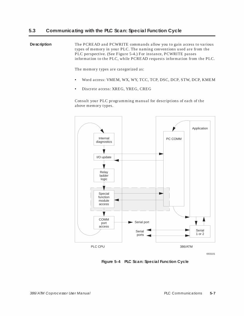
The PCREAD and PCWRITE commands allow you to gain access to varioustypes of memory in your PLC. The naming conventions used are from thePLC perspective. (See Figure 5-4.) For instance, PCWRITE passesinformation to the PLC, while PCREAD requests information from the PLC.
The memory types are categorized as:
• Word access: VMEM, WX, WY, TCC, TCP, DSC, DCP, STW, DCP, KMEM
• Discrete access: XREG, YREG, CREG
Consult your PLC programming manual for descriptions of each of theabove memory types.
Internaldiagnostics
Relayladderlogic
Specialfunctionmoduleaccess
COMMport
access
PLC CPU
Application
386/ATM
PC COMM
Serial1 or 2
Serial port
Serialports
I003101
I/O update
Figure 5-4 PLC Scan: Special Function Cycle
Description
PLC Communications5-8 386/ATM Coprocessor User Manual
Communicating during PLC Scan: Special Function Cycle (continued)
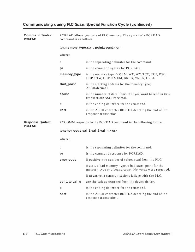
PCREAD allows you to read PLC memory. The syntax of a PCREADcommand is as follows.
:pr:memory_type:start_point:count::<cr>
where:
: is the separating delimiter for the command.
pr is the command syntax for PCREAD.
memory_type is the memory type: VMEM, WX, WY, TCC, TCP, DSC, DCP, STW, DCP, KMEM, XREG, YREG, CREG
start_point is the starting address for the memory type; ASCII/decimal.
count is the number of data items that you want to read in this transaction; ASCII/decimal.
:: is the ending delimiter for the command.
<cr> is the ASCII character 0D HEX denoting the end of the response transaction.
PCCOMM responds to the PCREAD command in the following format.
:pr:error_code:val_1:val_2:val_n::<cr>
where:
: is the separating delimiter for the command.
pr is the command response for PCREAD.
error_code if positive, the number of values read from the PLC
if zero, a bad memory_type, a bad start_point for the memory_type or a bound count. No words were returned.
if negative, a communications failure with the PLC.
val_1 to val_n are the values returned from the device driver.
:: is the ending delimiter for the command.
<cr> is the ASCII character 0D HEX denoting the end of the response transaction.
Command Syntax:PCREAD
Response Syntax:PCREAD
PLC Communications 5-9386/ATM Coprocessor User Manual
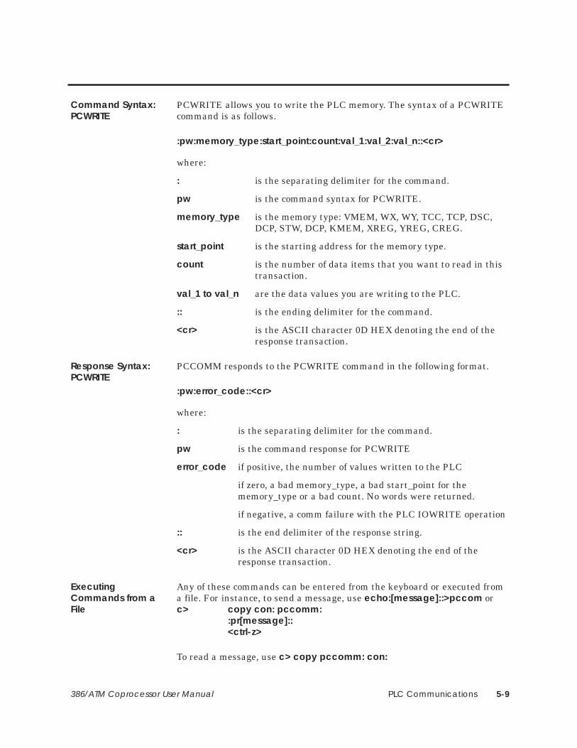
PCWRITE allows you to write the PLC memory. The syntax of a PCWRITEcommand is as follows.
:pw:memory_type:start_point:count:val_1:val_2:val_n::<cr>
where:
: is the separating delimiter for the command.
pw is the command syntax for PCWRITE.
memory_type is the memory type: VMEM, WX, WY, TCC, TCP, DSC, DCP, STW, DCP, KMEM, XREG, YREG, CREG.
start_point is the starting address for the memory type.
count is the number of data items that you want to read in this transaction.
val_1 to val_n are the data values you are writing to the PLC.
:: is the ending delimiter for the command.
<cr> is the ASCII character 0D HEX denoting the end of the response transaction.
PCCOMM responds to the PCWRITE command in the following format.
:pw:error_code::<cr>
where:
: is the separating delimiter for the command.
pw is the command response for PCWRITE
error_code if positive, the number of values written to the PLC
if zero, a bad memory_type, a bad start_point for the memory_type or a bad count. No words were returned.
if negative, a comm failure with the PLC IOWRITE operation
:: is the end delimiter of the response string.
<cr> is the ASCII character 0D HEX denoting the end of the response transaction.
Any of these commands can be entered from the keyboard or executed froma file. For instance, to send a message, use echo:[message]::>pccom or c> copy con: pccomm:
:pr[message]::<ctrl-z>
To read a message, use c> copy pccomm: con:
Command Syntax:PCWRITE
Response Syntax:PCWRITE
ExecutingCommands from aFile
PLC Communications5-10 386/ATM Coprocessor User Manual
Communicating during PLC Scan: Special Function Cycle (continued)
Example programs are included in Appendix B. Source code for theexamples is supplied on the 386/ATM device driver diskette.
Consider the following when reading or writing data.
• The PLC input scan, ladder execution, loop execution, or specialfunction logic may overwrite any value written by PCWRITE. Ensurethat all systems software and hardware are coordinated so that theywork together.
Care should be taken when using PCWRITE to send data to wordmemory areas. Unlike discrete memory points, word memory areascan be overwritten even if they are forced.
• All data and address values used in communications with PCCOMM arein decimal (i.e., 1, 2, 3, 4, 5, 6, 7, 8, 9, 10, 11, 12).
• When reading or writing a discrete memory type, the data will be either1 or 0.
Address for all memory types start with 1, with the exception of DCP,which starts with address 0.
The format for DCP addressing is:
<drum_number> <step_number>
where drum_number is 1 based (1 through n) and step_number is 0through 15.
Example:
Event drum 1, step 1 uses address 16 (base 10).
Event drum 1, step 2 uses address 17 (base 10).
Event drum 2, step 1 uses address 32 (base 10).
Event drum 2, step 2 uses address 33 (base 10).
Notes ConcerningWriting to MemoryLocations
CAUTION!

PLC Communications 5-11386/ATM Coprocessor User Manual
5.4 Communicating with the PLC: COMM Port Cycle
Internaldiagnostics
Relayladderlogic
Specialfunctionmoduleaccess
COMMport
access
PLC CPU
Application
386/ATM
PC COMM
Serial1 or 2
Serial port
Serialports
I003101
I/O update
Figure 5-5 PLC Scan: COMM Port Cycle
All third party software that communicates with Series 505 or Series 500families of PLCs through the PLC serial port will operate on the 386/ATM.Refer to the installation instructions accompanying the software package.
Com1 and Com2 are PC/AT-compatible serial communications ports withstandard handshaking. All third party PC/AT-compatible software that isprogrammed for serial communications will operate on the module.
NOTE: The driving voltage is 5 VDC rather than the 12 VDC standard ofIBM-compatible PCs and may not work with all hardware, especially amouse.
Serial Port to PLC
RS-232 Com1and Com2

Troubleshooting 6-1386/ATM Coprocessor User Manual
Chapter 6
Troubleshooting
6.1 Diagnostics 6-2. . . . . . . . . . . . . . . . . . . . . . . . . . . . . . . . . . . . . . . . . . . . . . . . . . . . . . . . . . . . . . . . . . . . . Power-up and Run-time Diagnostics 6-2. . . . . . . . . . . . . . . . . . . . . . . . . . . . . . . . . . . . . . . . . . . . . User-Initiated Diagnostic Tests 6-2. . . . . . . . . . . . . . . . . . . . . . . . . . . . . . . . . . . . . . . . . . . . . . . . . . .
6.2 Troubleshooting 6-3. . . . . . . . . . . . . . . . . . . . . . . . . . . . . . . . . . . . . . . . . . . . . . . . . . . . . . . . . . . . . . . . .
Troubleshooting6-2 386/ATM Coprocessor User Manual
6.1 Diagnostics
The 386/ATM has an extensive set of ROM-resident hardware diagnostics.Following power-up or a manual reset (using the reset button), the 386/ATMautomatically initiates a set of internal diagnostics to verify system memory,CPU, and functionality.
During operation, the 386/ATM generates and tests parity for each access tosystem DRAM to ensure integrity of the system DRAM memory.
You can initiate diagnostic testing at any time. Initiating diagnostic testinghalts the current operation. To begin, press: CNTL ALT S
Use the arrow keys to highlight DIAGNOSTICS and press Enter . The systemprompts you with information on selecting the diagnostic tests available.
The 386/ATM reboots after exiting the diagnostic menu.
NOTE: The Floppy Disk diagnostic requires a “scratch” 3.5″ high-densitydiskette (1.44M byte). All data on this diskette will be lost during theFloppy Drive test. The diskette will have to be reformatted before it can beused for MS-DOS applications. NOTE: The Fixed Disk test is non-destructive; no data on the fixed disk willbe lost as a result of the test.
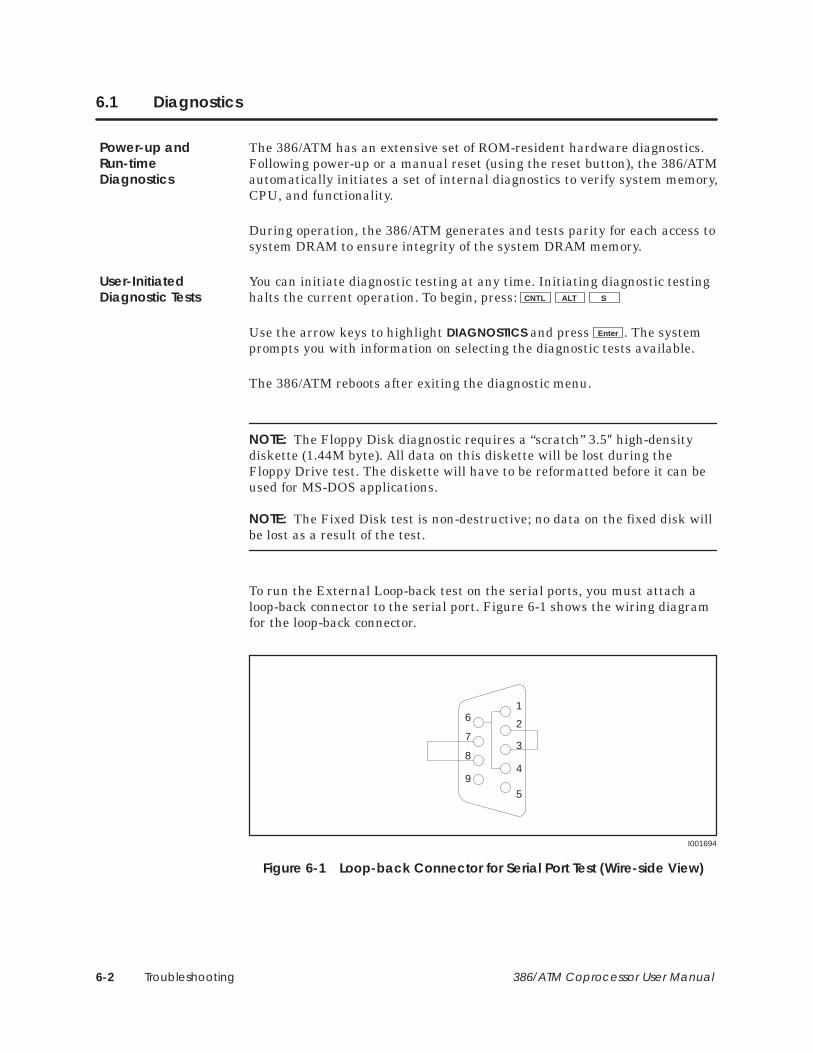
To run the External Loop-back test on the serial ports, you must attach aloop-back connector to the serial port. Figure 6-1 shows the wiring diagramfor the loop-back connector.
5
16
9
I001694
2
37
84
Figure 6-1 Loop-back Connector for Serial Port Test (Wire-side View)
Power-up andRun-timeDiagnostics
User-InitiatedDiagnostic Tests

Troubleshooting 6-3386/ATM Coprocessor User Manual
6.2 Troubleshooting
Condition Possible Cause Action
Does not run applicationsoftware
Software problem(application software)
Contact software vendor to verify:
• that software is IBM PC/AT-compatible.
• that software does not require special “keys” to operate.
If required, install special hardware or software as specified byvendor.
Hardware failure(module)
Run module diagnostic program.
Does not communicatewith PLC over I/O bus
Module not properlyseated in base
Check that module is properly installed in base.
Software problem (usingTISOFT)
Verify that 386ATM.EXE is installed in the CONFIG.SYS.
Start TISOFT by entering:
TI505 CVU (if you are communicating via the I/O bus); or
TI505 (if you are communicating via serial port 1); or
TI505 P2 (if you are communicating via serial port 2).
Software problem (usingapplication program)
Refer to manual for application program. Check operatinginstructions.
Verify that 386ATM.EXE is installed in the CONFIG.SYS.
Verify that third-party I/O bus driver software (if used) willwork. Contact software vendor.
Verify that PCREAD, PCWRITE, IOREAD, and IOWRITE areproperly formatted and have proper syntax in the applicationsoftware. Refer to Chapter 5 and Appendix C.
Does not communicatethrough serial ports
Cabling problem Check connections and cabling.
Incompatible communication interface
Check interface. 386/ATM is DTE; devices attached to serialports must be DCE, or must use appropriate crossover (e.g., nullmodem cable).
Software problem(application program)
Verify software by running serial application on anothermachine/module.
Hardware problem Run module diagnostic program, using loop-back connector tocheck serial ports.
Does not communicatethrough parallel port
Cabling problem Check connections and cabling.
Printer problem Check that printer is set for parallel communication. Verifyprinter operation.
Hardware problem Run module diagnostic program.
Video output notoperating properly
Module not set correctly(switch 4)
Verify switch 4 is on. Refer to Chapter 2.
Monitor not set correctly If monitor requires setting switches for EGA/VGA or TTL/analogoperation, verify that switches are set to VGA or analog.
Interconnecting cablemiswired or damaged
Verify wiring; see Appendix C.
Troubleshooting6-4 386/ATM Coprocessor User Manual
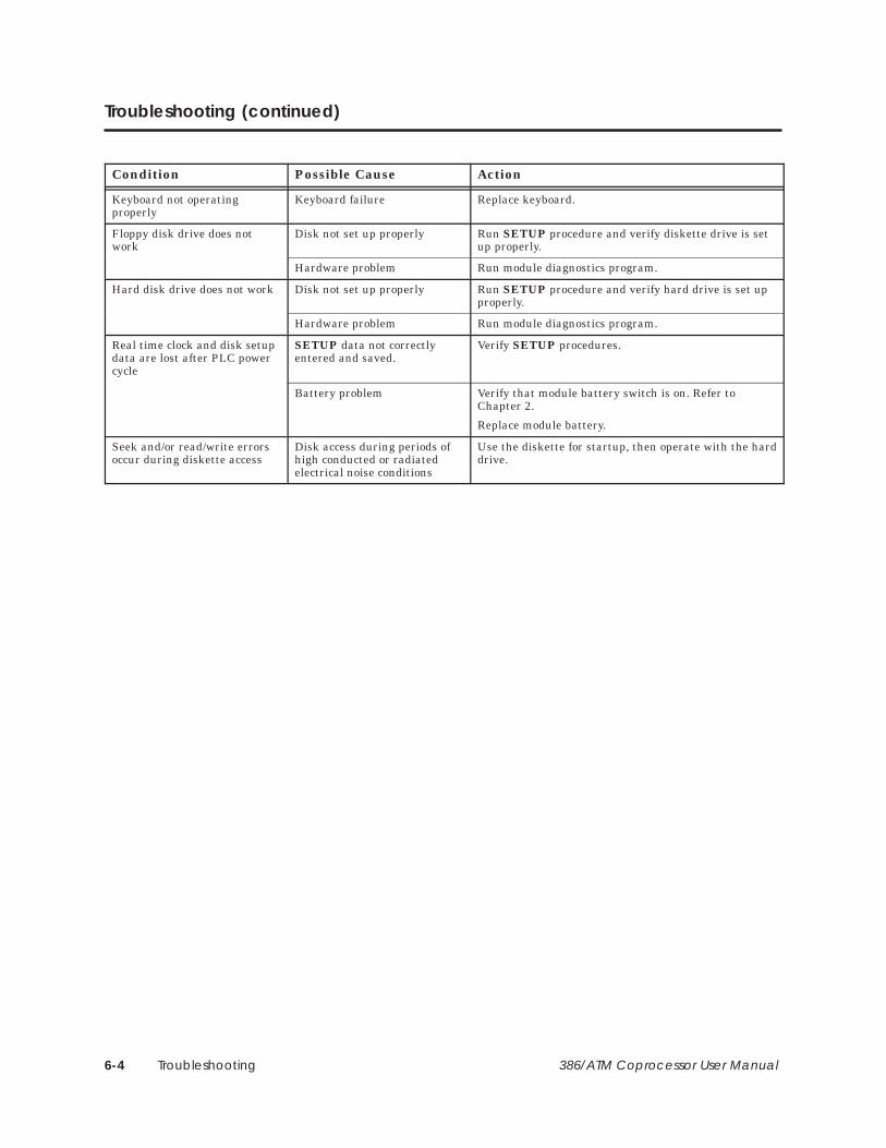
Troubleshooting (continued)
Condition Possible Cause Action
Keyboard not operatingproperly
Keyboard failure Replace keyboard.
Floppy disk drive does notwork
Disk not set up properly Run SETUP procedure and verify diskette drive is setup properly.
Hardware problem Run module diagnostics program.
Hard disk drive does not work Disk not set up properly Run SETUP procedure and verify hard drive is set upproperly.
Hardware problem Run module diagnostics program.
Real time clock and disk setupdata are lost after PLC powercycle
SETUP data not correctlyentered and saved.
Verify SETUP procedures.
Battery problem Verify that module battery switch is on. Refer toChapter 2.
Replace module battery.
Seek and/or read/write errorsoccur during diskette access
Disk access during periods ofhigh conducted or radiatedelectrical noise conditions
Use the diskette for startup, then operate with the harddrive.

387SX Math Coprocessor A-1386/ATM Coprocessor User Manual
Appendix A
387SX Math Coprocessor
A.1 Installing the 387SX Math Coprocessor A-2. . . . . . . . . . . . . . . . . . . . . . . . . . . . . . . . . . . . . . . . . . . Procedure A-3. . . . . . . . . . . . . . . . . . . . . . . . . . . . . . . . . . . . . . . . . . . . . . . . . . . . . . . . . . . . . . . . . . . . . .
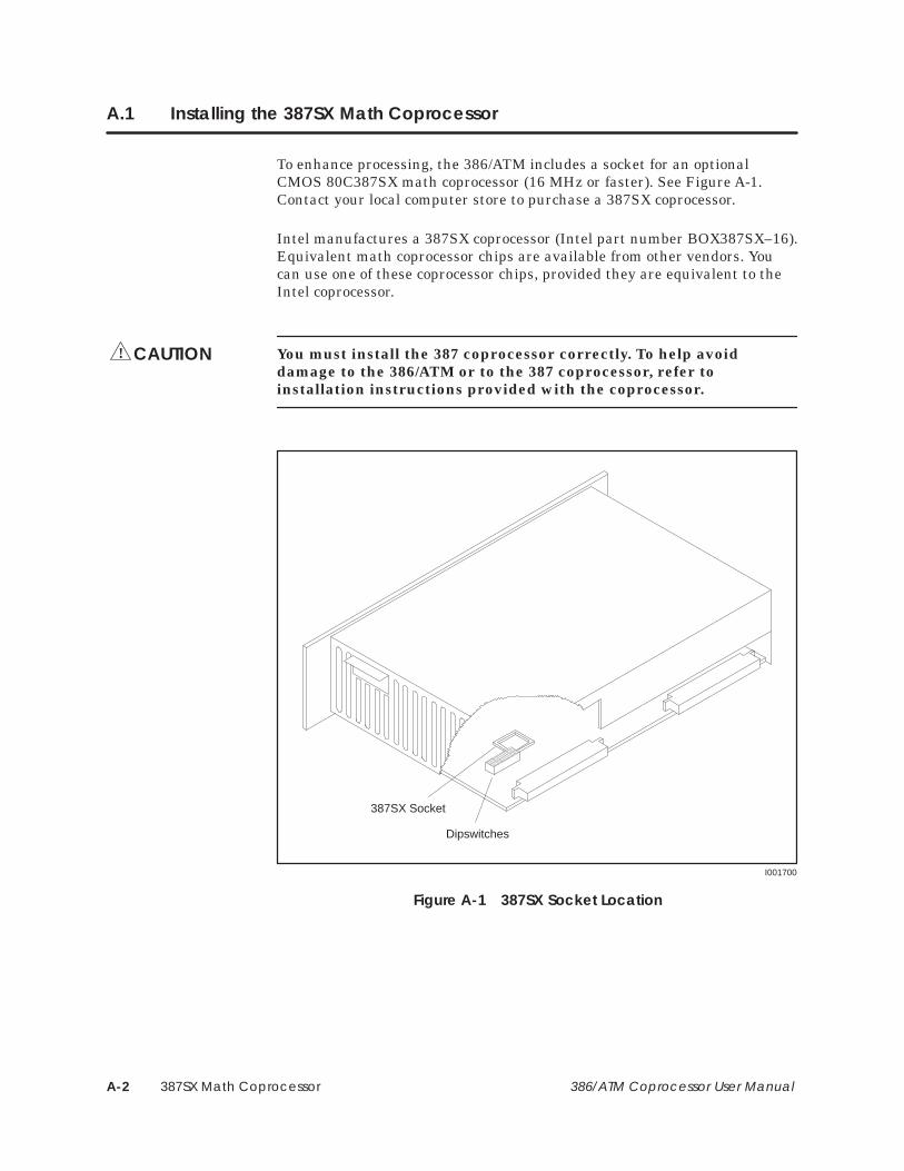
387SX Math CoprocessorA-2 386/ATM Coprocessor User Manual
A.1 Installing the 387SX Math Coprocessor
To enhance processing, the 386/ATM includes a socket for an optionalCMOS 80C387SX math coprocessor (16 MHz or faster). See Figure A-1.Contact your local computer store to purchase a 387SX coprocessor.
Intel manufactures a 387SX coprocessor (Intel part number BOX387SX–16).Equivalent math coprocessor chips are available from other vendors. Youcan use one of these coprocessor chips, provided they are equivalent to theIntel coprocessor.
You must install the 387 coprocessor correctly. To help avoiddamage to the 386/ATM or to the 387 coprocessor, refer toinstallation instructions provided with the coprocessor.
I001700
Dipswitches
387SX Socket
Figure A-1 387SX Socket Location
CAUTION!

387SX Math Coprocessor A-3386/ATM Coprocessor User Manual
Use the following procedure to install a 387 coprocessor in your 386/ATM.Refer to the installation instructions that accompany the 387SX coprocessor.
Both the 386/ATM and the 387 coprocessor can be damaged byelectrostatic discharge. To help avoid potential damage, groundyourself and the 386/ATM before handling and installing the 387coprocessor.
1. Place the 386/ATM on a flat surface, oriented as in Figure A-1 (with theprinted circuit board down).
2. Orient the 387 coprocessor chip to correspond to the socket. SeeFigure A-2.
3. Refer to the installation instructions that accompany the 387SXcoprocessor. Seat the 387 coprocessor into the socket by pressing firmlyand evenly. Be careful that the pins are not bent or damaged and thatthe printed circuit board is not flexed.
Notch
Front of module
I001701
Figure A-2 387SX Socket Orientation (Top View)
Procedure
CAUTION!

Programming Examples B-1386/ATM Coprocessor User Manual
Appendix B
Programming Examples
B.1 Overview B-2. . . . . . . . . . . . . . . . . . . . . . . . . . . . . . . . . . . . . . . . . . . . . . . . . . . . . . . . . . . . . . . . . . . . . . . PCCOMM Communication Examples B-2. . . . . . . . . . . . . . . . . . . . . . . . . . . . . . . . . . . . . . . . . . . . C Programs B-2. . . . . . . . . . . . . . . . . . . . . . . . . . . . . . . . . . . . . . . . . . . . . . . . . . . . . . . . . . . . . . . . . . . . . QuickBASIC Programs B-2. . . . . . . . . . . . . . . . . . . . . . . . . . . . . . . . . . . . . . . . . . . . . . . . . . . . . . . . . . . GW-BASIC Programs B-2. . . . . . . . . . . . . . . . . . . . . . . . . . . . . . . . . . . . . . . . . . . . . . . . . . . . . . . . . . . .
B.2 C Program: IOREAD B-3. . . . . . . . . . . . . . . . . . . . . . . . . . . . . . . . . . . . . . . . . . . . . . . . . . . . . . . . . . . . .
B.3 C Program: IOWRITE B-6. . . . . . . . . . . . . . . . . . . . . . . . . . . . . . . . . . . . . . . . . . . . . . . . . . . . . . . . . . . . .
B.4 C Program: PCREAD B-9. . . . . . . . . . . . . . . . . . . . . . . . . . . . . . . . . . . . . . . . . . . . . . . . . . . . . . . . . . . . .
B.5 C Program: PCWRITE B-13. . . . . . . . . . . . . . . . . . . . . . . . . . . . . . . . . . . . . . . . . . . . . . . . . . . . . . . . . . . .
B.6 QuickBASIC Program: IOREAD B-18. . . . . . . . . . . . . . . . . . . . . . . . . . . . . . . . . . . . . . . . . . . . . . . . . . .
B.7 QuickBASIC Program: IOWRITE B-21. . . . . . . . . . . . . . . . . . . . . . . . . . . . . . . . . . . . . . . . . . . . . . . . . . .
B.8 QuickBASIC Program: PCREAD B-24. . . . . . . . . . . . . . . . . . . . . . . . . . . . . . . . . . . . . . . . . . . . . . . . . . .
B.9 QuickBASIC Program: PCWRITE B-28. . . . . . . . . . . . . . . . . . . . . . . . . . . . . . . . . . . . . . . . . . . . . . . . . .
B.10 GW-BASIC Program: IOREAD B-33. . . . . . . . . . . . . . . . . . . . . . . . . . . . . . . . . . . . . . . . . . . . . . . . . . . . .
B.11 GW-BASIC Program: IOWRITE B-35. . . . . . . . . . . . . . . . . . . . . . . . . . . . . . . . . . . . . . . . . . . . . . . . . . . .
B.12 GW-BASIC Program: PCREAD B-38. . . . . . . . . . . . . . . . . . . . . . . . . . . . . . . . . . . . . . . . . . . . . . . . . . . .
B.13 GW-BASIC Program: PCWRITE B-42. . . . . . . . . . . . . . . . . . . . . . . . . . . . . . . . . . . . . . . . . . . . . . . . . . . .

Programming ExamplesB-2 386/ATM Coprocessor User Manual
B.1 Overview
The example programs are provided to demonstrate using the PCCOMMcommunications service. There are three sets of example programs, one foreach of the following languages: Microsoft GW-BASIC�, Microsoft QBasic(QuickBASIC), and C.
The following C programs have been successfully compiled and linked withMicrosoft C 5.1 and Turbo C� 2.0.
• iord_c: Read the coprocessor module’s WY values via IOREAD.
• iowr_c: Write to the coprocessor module’s WX values via IOWRITE.
• pcrd_c: Read from V-memory, X registers and the WX pointsvia PCREAD.
• pcwr_c: Write to V-memory, Y registers and the 386/ATM WY pointsvia PCWRITE.
Example programs for QuickBASIC are the following.
• iord_msb: Read the coprocessor module’s WY values via IOREAD.
• iowr_msb: Write to the coprocessor module’s WX values via IOWRITE.
• pcrd_msb: Read from V-memory, X registers and the 386/ATM WXpoints via PCREAD.
• pcwr_msb: Write to V-memory, Y registers and the 386/ATM WY pointsvia PCWRITE.
Example programs for GW-BASIC are the following.
• iord_gw: Read the coprocessor module’s WY values via IOREAD.
• iowr_gw: Write to the coprocessor module’s WX values via IOWRITE.
• pcrd_gw: Read from V-memory, X registers and the 386/ATM WXpoints via PCREAD.
• pcwr_gw: Write to V-memory, Y registers and the 386/ATM WY pointsvia PCWRITE.
NOTE: GW-BASIC is not furnished with the 386/ATM Coprocessor module.
PCCOMMCommunicationExamples
C Programs
QuickBASICPrograms
GW-BASICPrograms
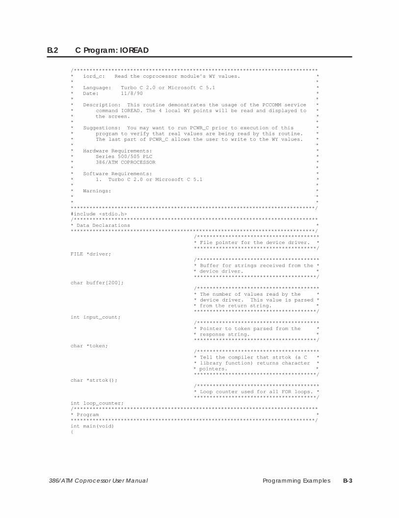
Programming Examples B-3386/ATM Coprocessor User Manual
B.2 C Program: IOREAD
/******************************************************************************* iord_c: Read the coprocessor module’s WY values. ** ** Language: Turbo C 2.0 or Microsoft C 5.1 ** Date: 11/8/90 ** ** Description: This routine demonstrates the usage of the PCCOMM service ** command IOREAD. The 4 local WY points will be read and displayed to ** the screen. ** ** Suggestions: You may want to run PCWR_C prior to execution of this ** program to verify that real values are being read by this routine. ** The last part of PCWR_C allows the user to write to the WY values. ** ** Hardware Requirements: ** Series 500/505 PLC ** 386/ATM COPROCESSOR ** ** Software Requirements: ** 1. Turbo C 2.0 or Microsoft C 5.1 ** ** Warnings: ** ** *******************************************************************************/#include <stdio.h>/******************************************************************************* Data Declarations *******************************************************************************/ /*************************************** * File pointer for the device driver. * ***************************************/FILE *driver; /*************************************** * Buffer for strings received from the * * device driver. * ***************************************/char buffer[200]; /*************************************** * The number of values read by the * * device driver. This value is parsed * * from the return string. * ***************************************/int input_count; /*************************************** * Pointer to token parsed from the * * response string. * ***************************************/char *token; /*************************************** * Tell the compiler that strtok (a C * * library function) returns character * * pointers. * ***************************************/char *strtok(); /*************************************** * Loop counter used for all FOR loops. * ***************************************/int loop_counter;/******************************************************************************* Program *******************************************************************************/int main(void){

Programming ExamplesB-4 386/ATM Coprocessor User Manual
C Program: IOREAD (continued)
/*************************************** * Display a message describing the * * program. * ***************************************/ printf(”\n\n\n\n”); printf(”IORD_C: Example usage of the PCCOMM command IOREAD to read”); printf(” from the\n module’s WY points.\n”); printf(”\nSee the file IORD_C.c for a more complete description of the”); printf(”\noperation of this routine.\n”); /*************************************** * Open the device driver in update * * mode (reading and writing). If it * * does not open correctly then exit * * the program with an error message. * ***************************************/ if ((driver = fopen(”PCCOMM”, ”r+”)) == NULL) { printf(”\nCould not open the device driver.\n”); exit(1); } /*************************************** * Write the request to the device * * driver. * ***************************************/ fprintf(driver, ”:IR:5:4::\r”); /*************************************** * Flush the file buffer to ensure that * * the driver received the request. * ***************************************/ fflush(driver); /*************************************** * The file pointer must be returned to * * the beginning of the file after each * * transaction with the device driver. * ***************************************/ fseek(driver,0L,SEEK_SET); /*************************************** * Get a response from the device * * driver. * ***************************************/ fgets(buffer, 199, driver); fseek(driver,0L,SEEK_SET); /*************************************** * Skip to the 2nd token in the response* * string (it contains the number of * * values read). * ***************************************/ strtok(buffer, ”:”); token = strtok(NULL, ”:”); input_count = atoi(token); /*************************************** * Print an error message if the number * * of values read does not equal 4. * ***************************************/ if (input_count != 4) printf(”\nThe device driver was unable to read the 4 values!”); else {

Programming Examples B-5386/ATM Coprocessor User Manual
/*************************************** * Display the 4 values to the screen. * ***************************************/ for (loop_counter = 0; loop_counter < 4; ++loop_counter) { token = strtok(NULL, ”:”); printf(”\nLocation %d: %05u”, loop_counter + 5, atoi(token)); } printf(”\n”); }}

Programming ExamplesB-6 386/ATM Coprocessor User Manual
B.3 C Program: IOWRITE
/******************************************************************************* iowr_c: Write to the coprocessor module’s WX values. ** ** Language: Turbo C 2.0 or Microsoft C 5.1 ** Date: 11/8/90 ** ** Description: This routine demonstrates the usage of the PCCOMM service ** command IOWRITE. The 4 local WX points will be written as specified ** by the user. ** ** Suggestions: You may want to run PCRD_C after this program to verify ** that the values were written correctly by this routine. The last ** part of PCRD_C allows the user to read the WX values. ** ** Hardware Requirements: ** Series 500/505 PLC ** 386/ATM COPROCESSOR ** ** Software Requirements: ** 1. Turbo C 2.0 or Microsoft C 5.1 ** ** Warnings: ** ** *******************************************************************************/#include <stdio.h>/******************************************************************************* Data Declarations *******************************************************************************/ /*************************************** * File pointer for the device driver. * ***************************************/FILE *driver; /*************************************** * Buffer for strings received from the * * device driver. * ***************************************/char buffer[200]; /*************************************** * The number of values written by the * * device driver. This value is parsed * * from the return string. * ***************************************/int input_count; /*************************************** * Pointer to token parsed from the * * response string. * ***************************************/char *token; /*************************************** * Tell the compiler that strtok (a C * * library function) returns character * * pointers. * ***************************************/char *strtok(); /*************************************** * Loop counter used for all FOR loops. * ***************************************/int loop_counter; /*************************************** * Storage for values that are to be * * written to the 4 local WX points. * ***************************************/int values[4];
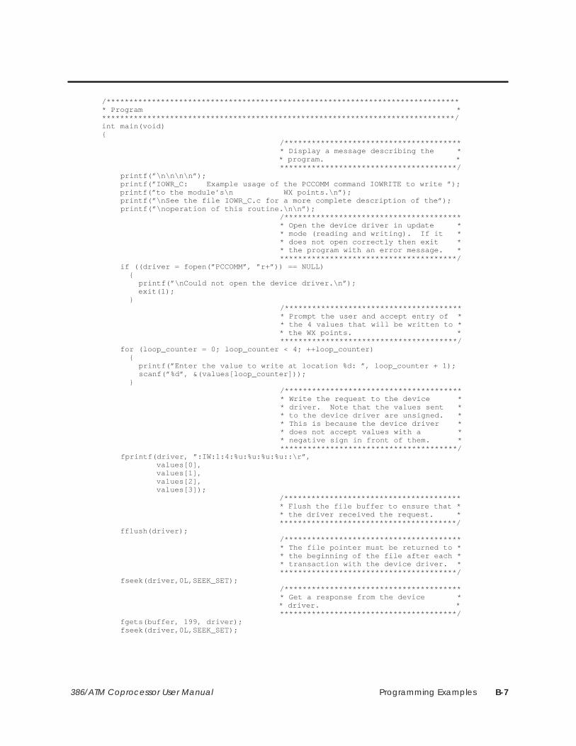
Programming Examples B-7386/ATM Coprocessor User Manual
/******************************************************************************* Program *******************************************************************************/int main(void){ /*************************************** * Display a message describing the * * program. * ***************************************/ printf(”\n\n\n\n”); printf(”IOWR_C: Example usage of the PCCOMM command IOWRITE to write ”); printf(”to the module’s\n WX points.\n”); printf(”\nSee the file IOWR_C.c for a more complete description of the”); printf(”\noperation of this routine.\n\n”); /*************************************** * Open the device driver in update * * mode (reading and writing). If it * * does not open correctly then exit * * the program with an error message. * ***************************************/ if ((driver = fopen(”PCCOMM”, ”r+”)) == NULL) { printf(”\nCould not open the device driver.\n”); exit(1); } /*************************************** * Prompt the user and accept entry of * * the 4 values that will be written to * * the WX points. * ***************************************/ for (loop_counter = 0; loop_counter < 4; ++loop_counter) { printf(”Enter the value to write at location %d: ”, loop_counter + 1); scanf(”%d”, &(values[loop_counter])); } /*************************************** * Write the request to the device * * driver. Note that the values sent * * to the device driver are unsigned. * * This is because the device driver * * does not accept values with a * * negative sign in front of them. * ***************************************/ fprintf(driver, ”:IW:1:4:%u:%u:%u:%u::\r”, values[0], values[1], values[2], values[3]); /*************************************** * Flush the file buffer to ensure that * * the driver received the request. * ***************************************/ fflush(driver); /*************************************** * The file pointer must be returned to * * the beginning of the file after each * * transaction with the device driver. * ***************************************/ fseek(driver,0L,SEEK_SET); /*************************************** * Get a response from the device * * driver. * ***************************************/ fgets(buffer, 199, driver); fseek(driver,0L,SEEK_SET);

Programming ExamplesB-8 386/ATM Coprocessor User Manual
C Program: IOWRITE (continued)
/*************************************** * Skip to the 2nd token in the response* * string (it contains the number of * * values written). * ***************************************/ strtok(buffer, ”:”); token = strtok(NULL, ”:”); input_count = atoi(token); /*************************************** * Print an error message if the number * * of values written does not equal 4. * ***************************************/ if (input_count != 4) printf(”\nThe device driver was unable to write the 4 values!”);}

Programming Examples B-9386/ATM Coprocessor User Manual
B.4 C Program: PCREAD
/******************************************************************************* pcrd_c: Read from V–mem, X registers and the coprocessor module’s ** WX points via PCREAD. ** ** Language: Turbo C 2.0 or Microsoft C 5.1 ** Date: 11/8/90 ** ** Description: This routine demonstrates the usage of the PCCOMM service ** command PCREAD. V–memory, X registers and the module’s WX points ** will be read and displayed to the screen. ** The first part of the program will let the user read from 8 ** consecutive V–memory locations. The user is prompted to enter ** an integer value which specifies the first V–memory location to read ** from. Then the 8 values are displayed to the screen. An error ** message will be displayed if the device driver was unable to read ** the 8 values from the PLC. ** The second part of the program will let the user read 8 discrete ** X register values. The user is prompted to enter an integer value ** which specifies the first X register location of the 8 to read from. ** Then the 8 values are read and displayed on the screen. ** The final section of the program will allow the user to read from ** the module’s 4 WX locations. The user is prompted to enter an ** integer value which specifies the first WX register location of the ** module. Then the values are displayed to the screen. ** ** Suggestions: You may want to run the routines PCWR_C and IOWR_C ** prior to execution of this routine to verify that real values are ** being read back from the PLC. PCWR_C can be used to write to ** v–memory and discrete locations, and IOWR_C can be used to write to ** the 4 WX values on the module. ** ** Hardware Requirements: ** Series 500/505 PLC ** 386/ATM COPROCESSOR ** ** Software Requirements: ** 1. Turbo C 2.0 or Microsoft C 5.1 ** ** Warnings: ** ** *******************************************************************************/#include <stdio.h>/******************************************************************************* Data Declarations *******************************************************************************/ /*************************************** * File pointer for the device driver. * ***************************************/FILE *driver; /*************************************** * Buffer for strings received from the * * device driver. * ***************************************/char buffer[200]; /*************************************** * The number of values read by the * * device driver. This value is parsed * * from the return string. * ***************************************/int input_count; /*************************************** * The beginning location that the * * series of data is to be read from. * ***************************************/int start_point;
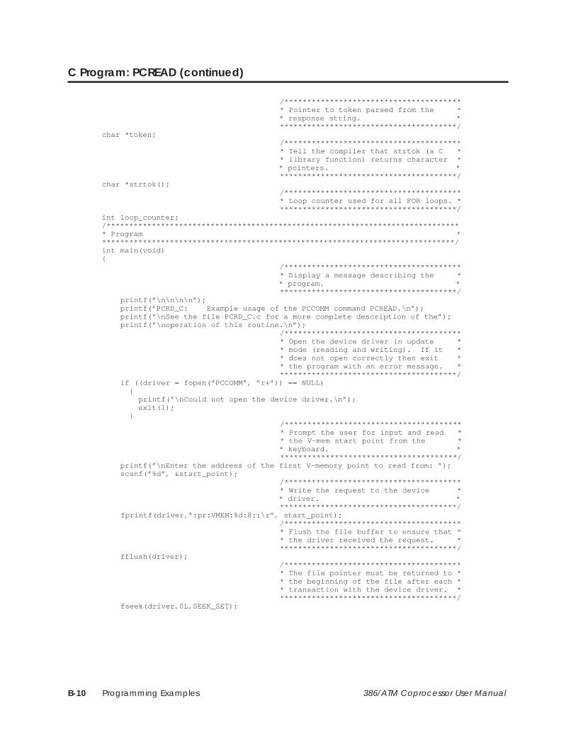
Programming ExamplesB-10 386/ATM Coprocessor User Manual
C Program: PCREAD (continued)
/*************************************** * Pointer to token parsed from the * * response string. * ***************************************/char *token; /*************************************** * Tell the compiler that strtok (a C * * library function) returns character * * pointers. * ***************************************/char *strtok(); /*************************************** * Loop counter used for all FOR loops. * ***************************************/int loop_counter;/******************************************************************************* Program *******************************************************************************/int main(void){ /*************************************** * Display a message describing the * * program. * ***************************************/ printf(”\n\n\n\n”); printf(”PCRD_C: Example usage of the PCCOMM command PCREAD.\n”); printf(”\nSee the file PCRD_C.c for a more complete description of the”); printf(”\noperation of this routine.\n”); /*************************************** * Open the device driver in update * * mode (reading and writing). If it * * does not open correctly then exit * * the program with an error message. * ***************************************/ if ((driver = fopen(”PCCOMM”, ”r+”)) == NULL) { printf(”\nCould not open the device driver.\n”); exit(1); } /*************************************** * Prompt the user for input and read * * the V–mem start point from the * * keyboard. * ***************************************/ printf(”\nEnter the address of the first V–memory point to read from: ”); scanf(”%d”, &start_point); /*************************************** * Write the request to the device * * driver. * ***************************************/ fprintf(driver,”:pr:VMEM:%d:8::\r”, start_point); /*************************************** * Flush the file buffer to ensure that * * the driver received the request. * ***************************************/ fflush(driver); /*************************************** * The file pointer must be returned to * * the beginning of the file after each * * transaction with the device driver. * ***************************************/ fseek(driver,0L,SEEK_SET);
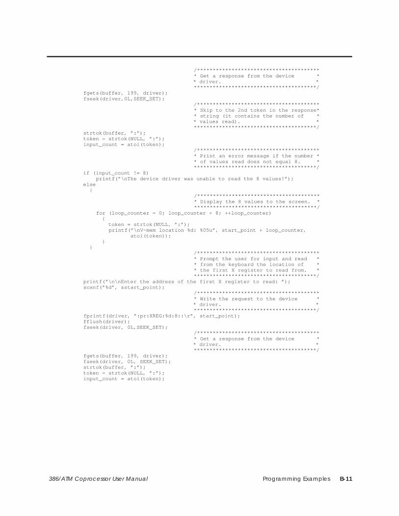
Programming Examples B-11386/ATM Coprocessor User Manual
/*************************************** * Get a response from the device * * driver. * ***************************************/ fgets(buffer, 199, driver); fseek(driver,0L,SEEK_SET); /*************************************** * Skip to the 2nd token in the response* * string (it contains the number of * * values read). * ***************************************/ strtok(buffer, ”:”); token = strtok(NULL, ”:”); input_count = atoi(token); /*************************************** * Print an error message if the number * * of values read does not equal 8. * ***************************************/ if (input_count != 8) printf(”\nThe device driver was unable to read the 8 values!”); else { /*************************************** * Display the 8 values to the screen. * ***************************************/ for (loop_counter = 0; loop_counter < 8; ++loop_counter) { token = strtok(NULL, ”:”); printf(”\nV–mem location %d: %05u”, start_point + loop_counter, atoi(token)); } } /*************************************** * Prompt the user for input and read * * from the keyboard the location of * * the first X register to read from. * ***************************************/ printf(”\n\nEnter the address of the first X register to read: ”); scanf(”%d”, &start_point); /*************************************** * Write the request to the device * * driver. * ***************************************/ fprintf(driver, ”:pr:XREG:%d:8::\r”, start_point); fflush(driver); fseek(driver, 0L,SEEK_SET); /*************************************** * Get a response from the device * * driver. * ***************************************/ fgets(buffer, 199, driver); fseek(driver, 0L, SEEK_SET); strtok(buffer, ”:”); token = strtok(NULL, ”:”); input_count = atoi(token);

Programming ExamplesB-12 386/ATM Coprocessor User Manual
C Program: PCREAD (continued)
/*************************************** * Print an error message if the number * * of values read does not equal 8. * ***************************************/ if (input_count != 8) printf(”\nThe device driver was unable to read the 8 values!”); else { /*************************************** * Display the 8 values to the screen. * ***************************************/ for (loop_counter = 0; loop_counter < 8; ++loop_counter) { token = strtok(NULL, ”:”); printf(”\nX%d: %u”, start_point + loop_counter, atoi(token)); } } /*************************************** * Prompt the user for input and read * * from the keyboard the location of * * the first WX to read from. * ***************************************/ printf(”\n\nEnter the address of the first WX register on the module: ”); scanf(”%d”, &start_point); /*************************************** * Write the request to the device * * driver. * ***************************************/ fprintf(driver, ”:pr:WX:%d:4::\r”, start_point); fflush(driver); fseek(driver, 0L, SEEK_SET); /*************************************** * Get a response from the device * * driver. * ***************************************/ fgets(buffer, 199, driver); fseek(driver, 0L, SEEK_SET); strtok(buffer, ”:”); token = strtok(NULL, ”:”); input_count = atoi(token); /*************************************** * Print an error message if the number * * of values read does not equal 4. * ***************************************/ if (input_count != 4) printf(”\nThe device driver was unable to read the 4 values!”); else { /*************************************** * Display the 4 values to the screen. * ***************************************/ for (loop_counter = 0; loop_counter < 4; ++loop_counter) { token = strtok(NULL, ”:”); printf(”\nWX%d: %05u”, start_point + loop_counter, atoi(token)); } } printf(”\n”);}
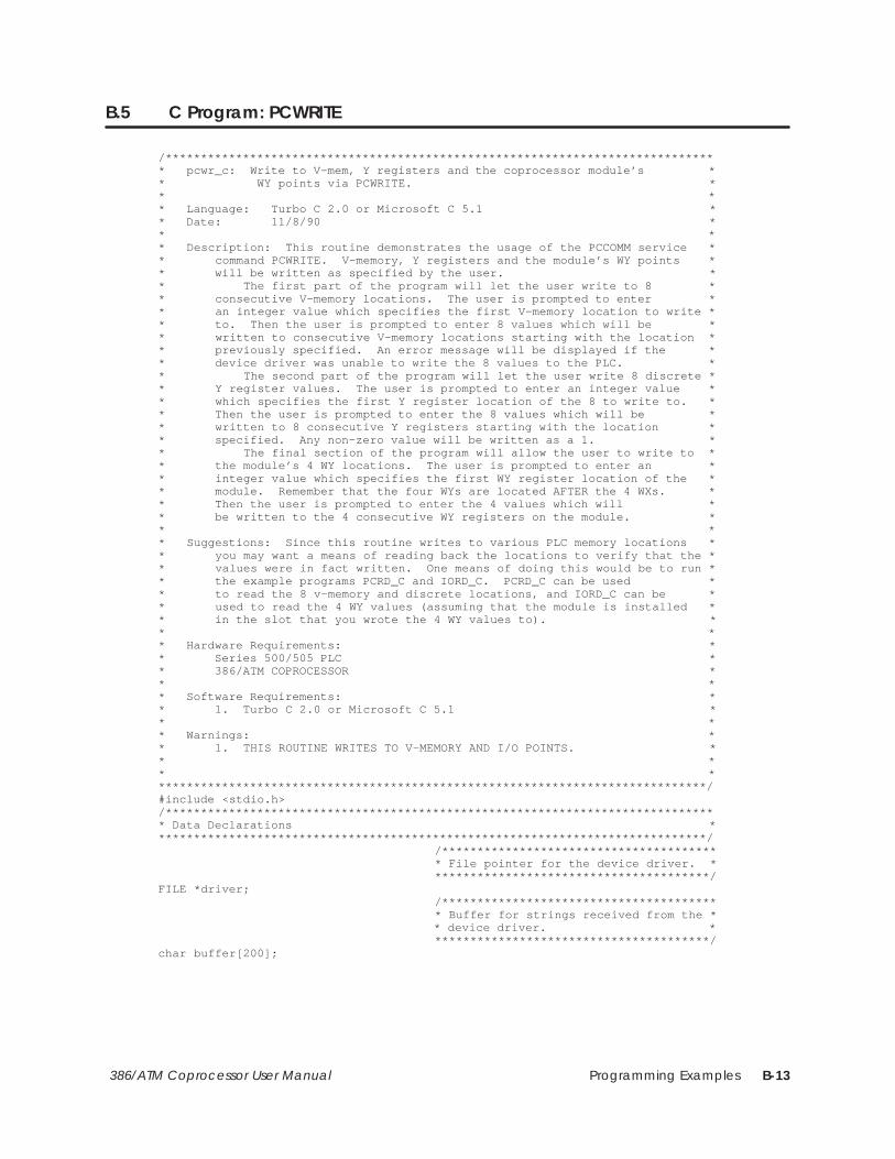
Programming Examples B-13386/ATM Coprocessor User Manual
B.5 C Program: PCWRITE
/******************************************************************************* pcwr_c: Write to V–mem, Y registers and the coprocessor module’s ** WY points via PCWRITE. ** ** Language: Turbo C 2.0 or Microsoft C 5.1 ** Date: 11/8/90 ** ** Description: This routine demonstrates the usage of the PCCOMM service ** command PCWRITE. V–memory, Y registers and the module’s WY points ** will be written as specified by the user. ** The first part of the program will let the user write to 8 ** consecutive V–memory locations. The user is prompted to enter ** an integer value which specifies the first V–memory location to write ** to. Then the user is prompted to enter 8 values which will be ** written to consecutive V–memory locations starting with the location ** previously specified. An error message will be displayed if the ** device driver was unable to write the 8 values to the PLC. ** The second part of the program will let the user write 8 discrete ** Y register values. The user is prompted to enter an integer value ** which specifies the first Y register location of the 8 to write to. ** Then the user is prompted to enter the 8 values which will be ** written to 8 consecutive Y registers starting with the location ** specified. Any non–zero value will be written as a 1. ** The final section of the program will allow the user to write to ** the module’s 4 WY locations. The user is prompted to enter an ** integer value which specifies the first WY register location of the ** module. Remember that the four WYs are located AFTER the 4 WXs. ** Then the user is prompted to enter the 4 values which will ** be written to the 4 consecutive WY registers on the module. ** ** Suggestions: Since this routine writes to various PLC memory locations ** you may want a means of reading back the locations to verify that the ** values were in fact written. One means of doing this would be to run ** the example programs PCRD_C and IORD_C. PCRD_C can be used ** to read the 8 v–memory and discrete locations, and IORD_C can be ** used to read the 4 WY values (assuming that the module is installed ** in the slot that you wrote the 4 WY values to). ** ** Hardware Requirements: ** Series 500/505 PLC ** 386/ATM COPROCESSOR ** ** Software Requirements: ** 1. Turbo C 2.0 or Microsoft C 5.1 ** ** Warnings: ** 1. THIS ROUTINE WRITES TO V–MEMORY AND I/O POINTS. ** ** *******************************************************************************/#include <stdio.h>/******************************************************************************* Data Declarations *******************************************************************************/ /*************************************** * File pointer for the device driver. * ***************************************/FILE *driver; /*************************************** * Buffer for strings received from the * * device driver. * ***************************************/char buffer[200];

Programming ExamplesB-14 386/ATM Coprocessor User Manual
C Program: PCWRITE (continued)
/*************************************** * The number of values written by the * * device driver. This value is parsed * * from the return string. * ***************************************/int input_count; /*************************************** * The beginning location that the * * series of data is to be written to. * ***************************************/int start_point; /*************************************** * Storage for 8 discrete or word * * values that are to be written. * ***************************************/int values[8]; /*************************************** * Pointer to token parsed from the * * response string. * ***************************************/char *token; /*************************************** * Tell the compiler that strtok (a C * * library function) returns character * * pointers. * ***************************************/char *strtok(); /*************************************** * Loop counter used for all FOR loops. * ***************************************/int loop_counter;/******************************************************************************* Program *******************************************************************************/int main(void){ /*************************************** * Display a message describing the * * program. * ***************************************/ printf(”\n\n\n\n”); printf(”PCWR_C: Example usage of the PCCOMM command PCWRITE.\n”); printf(”\nSee the file PCWR_C.c for a more complete description of the”); printf(”\noperation of this routine.\n”); /*************************************** * Print a warning message. * ***************************************/ printf(”\nWARNING: This program writes to V–memory and Y–registers!\n”); printf(”Hit <space> to continue and any other key to exit.\n\n”); if (getch() != ’ ’) exit(1); /*************************************** * Open the device driver in update * * mode (reading and writing). If it * * does not open correctly then exit * * the program with an error message. * ***************************************/ if ((driver = fopen(”PCCOMM”, ”r+”)) == NULL) { printf(”\nCould not open the device driver.\n\n”); exit(1); }
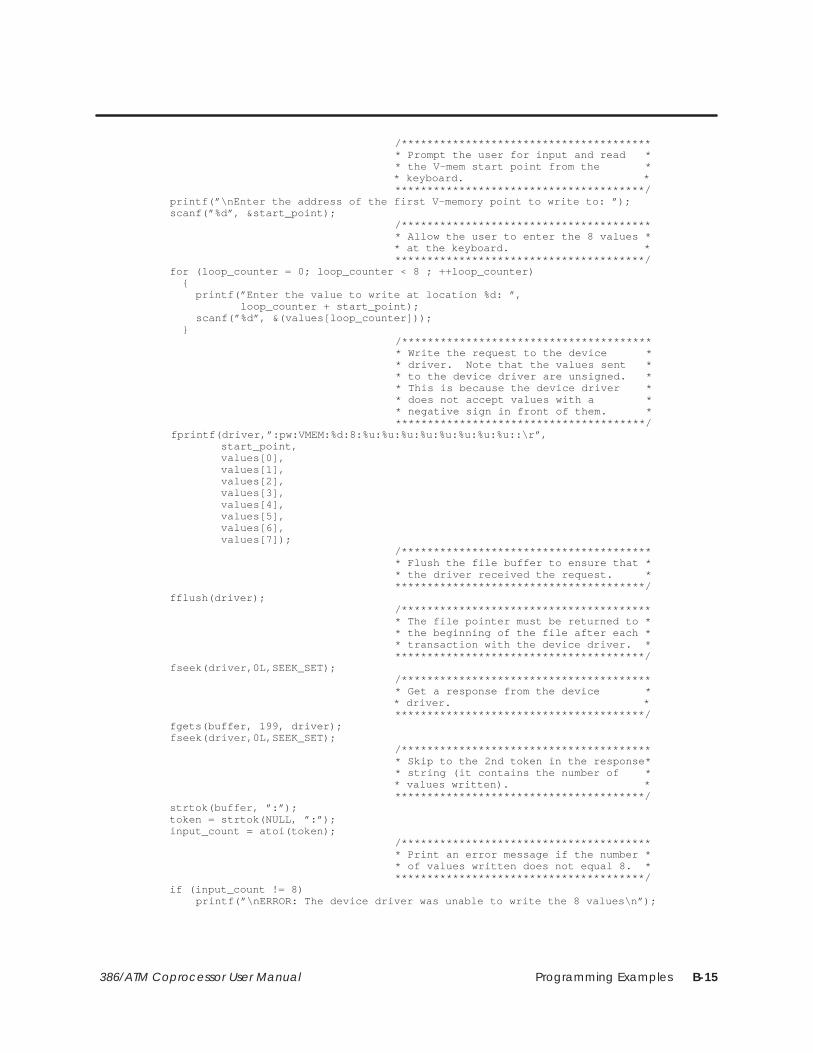
Programming Examples B-15386/ATM Coprocessor User Manual
/*************************************** * Prompt the user for input and read * * the V–mem start point from the * * keyboard. * ***************************************/ printf(”\nEnter the address of the first V–memory point to write to: ”); scanf(”%d”, &start_point); /*************************************** * Allow the user to enter the 8 values * * at the keyboard. * ***************************************/ for (loop_counter = 0; loop_counter < 8 ; ++loop_counter) { printf(”Enter the value to write at location %d: ”, loop_counter + start_point); scanf(”%d”, &(values[loop_counter])); } /*************************************** * Write the request to the device * * driver. Note that the values sent * * to the device driver are unsigned. * * This is because the device driver * * does not accept values with a * * negative sign in front of them. * ***************************************/ fprintf(driver,”:pw:VMEM:%d:8:%u:%u:%u:%u:%u:%u:%u:%u::\r”, start_point, values[0], values[1], values[2], values[3], values[4], values[5], values[6], values[7]); /*************************************** * Flush the file buffer to ensure that * * the driver received the request. * ***************************************/ fflush(driver); /*************************************** * The file pointer must be returned to * * the beginning of the file after each * * transaction with the device driver. * ***************************************/ fseek(driver,0L,SEEK_SET); /*************************************** * Get a response from the device * * driver. * ***************************************/ fgets(buffer, 199, driver); fseek(driver,0L,SEEK_SET); /*************************************** * Skip to the 2nd token in the response* * string (it contains the number of * * values written). * ***************************************/ strtok(buffer, ”:”); token = strtok(NULL, ”:”); input_count = atoi(token); /*************************************** * Print an error message if the number * * of values written does not equal 8. * ***************************************/ if (input_count != 8) printf(”\nERROR: The device driver was unable to write the 8 values\n”);

Programming ExamplesB-16 386/ATM Coprocessor User Manual
C Program: PCWRITE (continued)
/*************************************** * Prompt the user for input and read * * from the keyboard the location of * * the first Y register to write to. * ***************************************/ printf(”\nEnter the address of the first Y register to write to: ”); scanf(”%d”, &start_point); /*************************************** * Allow the user to enter the 8 values * * at the keyboard. Any non–zero value * * is written as a 1. * ***************************************/ for (loop_counter = 0; loop_counter < 8; ++loop_counter) { printf(”Enter the value to write at Y%d: ”, start_point + loop_counter); scanf(”%d”, &(values[loop_counter])); } /*************************************** * Write the request to the device * * driver. * ***************************************/ fprintf(driver, ”:pw:YREG:%d:8:%u:%u:%u:%u:%u:%u:%u:%u::\r”, start_point, values[0], values[1], values[2], values[3], values[4], values[5], values[6], values[7]); fflush(driver); fseek(driver, 0L,SEEK_SET); /*************************************** * Get a response from the device * * driver. * ***************************************/ fgets(buffer, 199, driver); fseek(driver, 0L, SEEK_SET); strtok(buffer, ”:”); token = strtok(NULL, ”:”); input_count = atoi(token); /*************************************** * Print an error message if the number * * of values written does not equal 8. * ***************************************/ if (input_count != 8) printf(”\nERROR: The device driver was unable to write the 8 values\n”); /*************************************** * Prompt the user for input and read * * from the keyboard the location of * * the first WY to write to. * ***************************************/ printf(”\nEnter the address of the first WY register on the module: ”); scanf(”%d”, &start_point);

Programming Examples B-17386/ATM Coprocessor User Manual
/*************************************** * Allow the user to enter the 4 values * * that will be written to the module’s * * 4 WY points. * ***************************************/ for (loop_counter = 0; loop_counter < 4; ++loop_counter) { printf(”Enter the value to write at WY%d: ”, start_point + loop_counter); scanf(”%d”, &(values[loop_counter])); } /*************************************** * Write the request to the device * * driver. * ***************************************/ fprintf(driver, ”:pw:WY:%d:4:%u:%u:%u:%u::\r”, start_point, values[0], values[1], values[2], values[3]); fflush(driver); fseek(driver, 0L, SEEK_SET); /*************************************** * Get a response from the device * * driver. * ***************************************/ fgets(buffer, 199, driver); fseek(driver, 0L, SEEK_SET); strtok(buffer, ”:”); token = strtok(NULL, ”:”); input_count = atoi(token); /*************************************** * Print an error message if the number * * of values written does not equal 4. * ***************************************/ if (input_count != 4) printf(”\nERROR: The device driver was unable to write the 4 values\n”);}
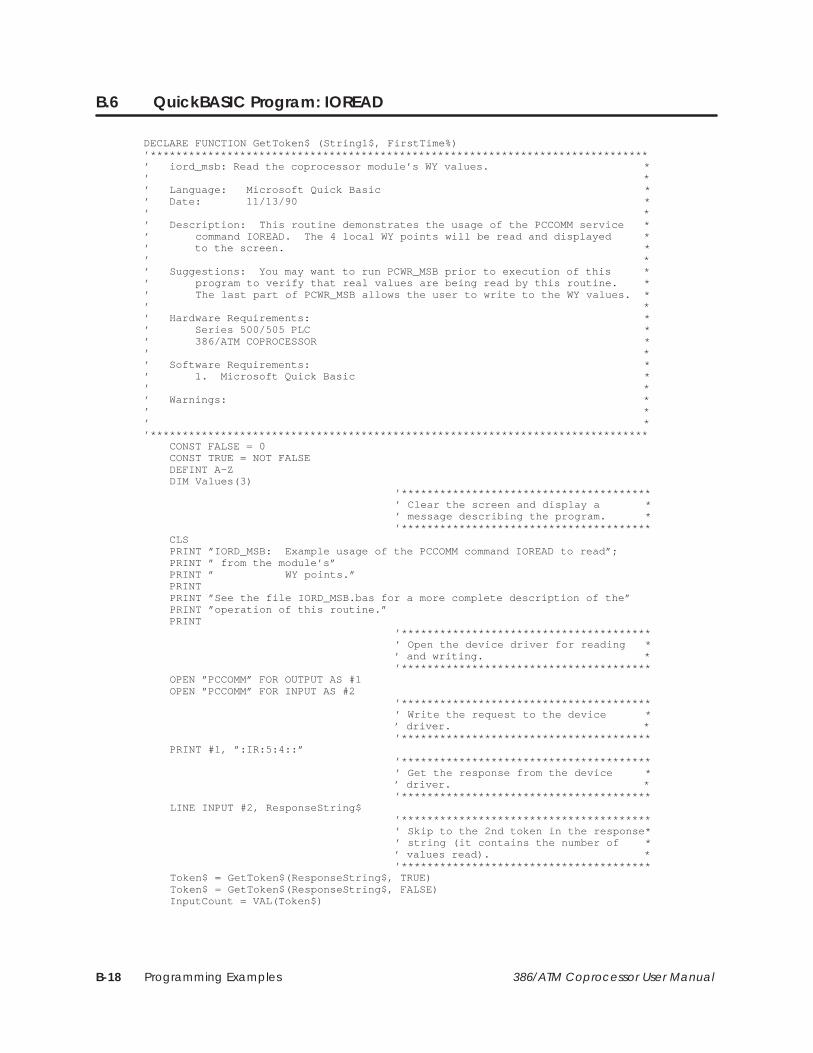
Programming ExamplesB-18 386/ATM Coprocessor User Manual
B.6 QuickBASIC Program: IOREAD
DECLARE FUNCTION GetToken$ (String1$, FirstTime%)’******************************************************************************’ iord_msb: Read the coprocessor module’s WY values. *’ *’ Language: Microsoft Quick Basic *’ Date: 11/13/90 *’ *’ Description: This routine demonstrates the usage of the PCCOMM service *’ command IOREAD. The 4 local WY points will be read and displayed *’ to the screen. *’ *’ Suggestions: You may want to run PCWR_MSB prior to execution of this *’ program to verify that real values are being read by this routine. *’ The last part of PCWR_MSB allows the user to write to the WY values. *’ *’ Hardware Requirements: *’ Series 500/505 PLC *’ 386/ATM COPROCESSOR *’ *’ Software Requirements: *’ 1. Microsoft Quick Basic *’ *’ Warnings: *’ *’ *’****************************************************************************** CONST FALSE = 0 CONST TRUE = NOT FALSE DEFINT A–Z DIM Values(3) ’*************************************** ’ Clear the screen and display a * ’ message describing the program. * ’*************************************** CLS PRINT ”IORD_MSB: Example usage of the PCCOMM command IOREAD to read”; PRINT ” from the module’s” PRINT ” WY points.” PRINT PRINT ”See the file IORD_MSB.bas for a more complete description of the” PRINT ”operation of this routine.” PRINT ’*************************************** ’ Open the device driver for reading * ’ and writing. * ’*************************************** OPEN ”PCCOMM” FOR OUTPUT AS #1 OPEN ”PCCOMM” FOR INPUT AS #2 ’*************************************** ’ Write the request to the device * ’ driver. * ’*************************************** PRINT #1, ”:IR:5:4::” ’*************************************** ’ Get the response from the device * ’ driver. * ’*************************************** LINE INPUT #2, ResponseString$ ’*************************************** ’ Skip to the 2nd token in the response* ’ string (it contains the number of * ’ values read). * ’*************************************** Token$ = GetToken$(ResponseString$, TRUE) Token$ = GetToken$(ResponseString$, FALSE) InputCount = VAL(Token$)
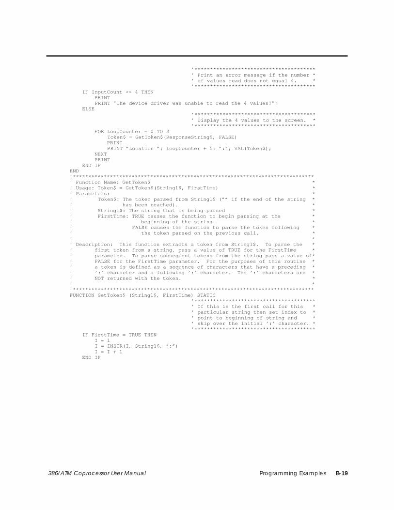
Programming Examples B-19386/ATM Coprocessor User Manual
’*************************************** ’ Print an error message if the number * ’ of values read does not equal 4. * ’*************************************** IF InputCount <> 4 THEN PRINT PRINT ”The device driver was unable to read the 4 values!”; ELSE ’*************************************** ’ Display the 4 values to the screen. * ’*************************************** FOR LoopCounter = 0 TO 3 Token$ = GetToken$(ResponseString$, FALSE) PRINT PRINT ”Location ”; LoopCounter + 5; ”:”; VAL(Token$); NEXT PRINT END IFEND’******************************************************************************’ Function Name: GetToken$ *’ Usage: Token$ = GetToken$(String1$, FirstTime) *’ Parameters: *’ Token$: The token parsed from String1$ (”” if the end of the string *’ has been reached). *’ String1$: The string that is being parsed *’ FirstTime: TRUE causes the function to begin parsing at the *’ beginning of the string. *’ FALSE causes the function to parse the token following *’ the token parsed on the previous call. *’ *’ Description: This function extracts a token from String1$. To parse the *’ first token from a string, pass a value of TRUE for the FirstTime *’ parameter. To parse subsequent tokens from the string pass a value of*’ FALSE for the FirstTime parameter. For the purposes of this routine *’ a token is defined as a sequence of characters that have a preceding *’ ’:’ character and a following ’:’ character. The ’:’ characters are *’ NOT returned with the token. *’ *’******************************************************************************FUNCTION GetToken$ (String1$, FirstTime) STATIC ’*************************************** ’ If this is the first call for this * ’ particular string then set index to * ’ point to beginning of string and * ’ skip over the initial ’:’ character. * ’*************************************** IF FirstTime = TRUE THEN I = 1 I = INSTR(I, String1$, ”:”) I = I + 1 END IF
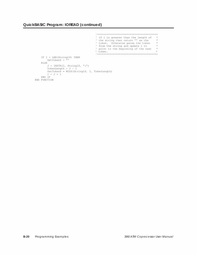
Programming ExamplesB-20 386/ATM Coprocessor User Manual
QuickBASIC Program: IOREAD (continued)
’*************************************** ’ If I is greater than the length of * ’ the string then return ”” as the * ’ token. Otherwise parse the token * ’ from the string and update I to * ’ point to the beginning of the next * ’ token. * ’*************************************** IF I > LEN(String1$) THEN GetToken$ = ”” ELSE J = INSTR(I, String1$, ”:”) TokenLength = J – I GetToken$ = MID$(String1$, I, TokenLength) I = J + 1 END IFEND FUNCTION
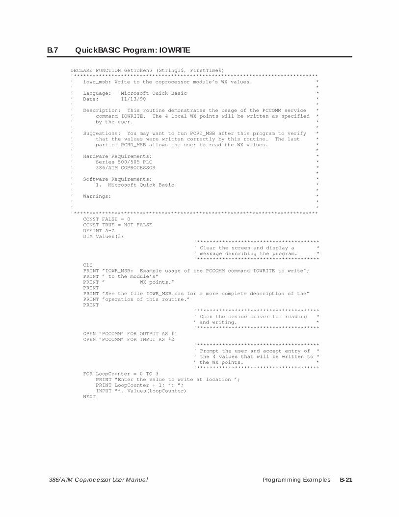
Programming Examples B-21386/ATM Coprocessor User Manual
B.7 QuickBASIC Program: IOWRITE
DECLARE FUNCTION GetToken$ (String1$, FirstTime%)’******************************************************************************’ iowr_msb: Write to the coprocessor module’s WX values. *’ *’ Language: Microsoft Quick Basic *’ Date: 11/13/90 *’ *’ Description: This routine demonstrates the usage of the PCCOMM service *’ command IOWRITE. The 4 local WX points will be written as specified *’ by the user. *’ *’ Suggestions: You may want to run PCRD_MSB after this program to verify *’ that the values were written correctly by this routine. The last *’ part of PCRD_MSB allows the user to read the WX values. *’ *’ Hardware Requirements: *’ Series 500/505 PLC *’ 386/ATM COPROCESSOR *’ *’ Software Requirements: *’ 1. Microsoft Quick Basic *’ *’ Warnings: *’ *’ *’****************************************************************************** CONST FALSE = 0 CONST TRUE = NOT FALSE DEFINT A–Z DIM Values(3) ’*************************************** ’ Clear the screen and display a * ’ message describing the program. * ’*************************************** CLS PRINT ”IOWR_MSB: Example usage of the PCCOMM command IOWRITE to write”; PRINT ” to the module’s” PRINT ” WX points.” PRINT PRINT ”See the file IOWR_MSB.bas for a more complete description of the” PRINT ”operation of this routine.” PRINT ’*************************************** ’ Open the device driver for reading * ’ and writing. * ’*************************************** OPEN ”PCCOMM” FOR OUTPUT AS #1 OPEN ”PCCOMM” FOR INPUT AS #2 ’*************************************** ’ Prompt the user and accept entry of * ’ the 4 values that will be written to * ’ the WX points. * ’*************************************** FOR LoopCounter = 0 TO 3 PRINT ”Enter the value to write at location ”; PRINT LoopCounter + 1; ”: ”; INPUT ””, Values(LoopCounter) NEXT

Programming ExamplesB-22 386/ATM Coprocessor User Manual
QuickBASIC Program: IOWRITE (continued)
’*************************************** ’ Write the request to the device * ’ driver. Note that leading blanks * ’ are removed from Values() via * ’ LTRIM$. * ’*************************************** RequestString$ = ”:iw:1:4” FOR LoopCounter = 0 TO 3 RequestString$ = RequestString$ + ”:” RequestString$ = RequestString$ + LTRIM$(STR$(Values(LoopCounter))) NEXT RequestString$ = RequestString$ + ”::” PRINT #1, RequestString$ ’*************************************** ’ Get a response from the device * ’ driver. * ’*************************************** LINE INPUT #2, ResponseString$ ’*************************************** ’ Skip to the 2nd token in the response* ’ string (it contains the number of * ’ values written). * ’*************************************** Token$ = GetToken$(ResponseString$, TRUE) Token$ = GetToken$(ResponseString$, FALSE) InputCount = VAL(Token$) ’*************************************** ’ Print an error message if the number * ’ of values written does not equal 4. * ’*************************************** IF InputCount <> 4 THEN PRINT PRINT ”The device driver was unable to write the 4 values!”; END IF PRINTEND’******************************************************************************’ Function Name: GetToken$ *’ Usage: Token$ = GetToken$(String1$, FirstTime) *’ Parameters: *’ Token$: The token parsed from String1$ (”” if the end of the string *’ has been reached). *’ String1$: The string that is being parsed *’ FirstTime: TRUE causes the function to begin parsing at the *’ beginning of the string. *’ FALSE causes the function to parse the token following *’ the token parsed on the previous call. *’ *’ Description: This function extracts a token from String1$. To parse the *’ first token from a string, pass a value of TRUE for the FirstTime *’ parameter. To parse subsequent tokens from the string pass a value of*’ FALSE for the FirstTime parameter. For the purposes of this routine *’ a token is defined as a sequence of characters that have a preceding *’ ’:’ character and a following ’:’ character. The ’:’ characters are *’ NOT returned with the token. *’ *’******************************************************************************FUNCTION GetToken$ (String1$, FirstTime) STATIC

Programming Examples B-23386/ATM Coprocessor User Manual
’*************************************** ’ If this is the first call for this * ’ particular string then set index to * ’ point to beginning of string and * ’ skip over the initial ’:’ character. * ’*************************************** IF FirstTime = TRUE THEN I = 1 I = INSTR(I, String1$, ”:”) I = I + 1 END IF ’*************************************** ’ If I is greater than the length of * ’ the string then return ”” as the * ’ token. Otherwise parse the token * ’ from the string and update I to * ’ point to the beginning of the next * ’ token. * ’*************************************** IF I > LEN(String1$) THEN GetToken$ = ”” ELSE J = INSTR(I, String1$, ”:”) TokenLength = J – I GetToken$ = MID$(String1$, I, TokenLength) I = J + 1 END IFEND FUNCTION

Programming ExamplesB-24 386/ATM Coprocessor User Manual
B.8 QuickBASIC Program: PCREAD
DECLARE FUNCTION GetToken$ (String1$, FirstTime%)’******************************************************************************’ pcrd_msb: Read from V–mem, X registers and the coprocessor module’s *’ WX points via PCREAD. *’ *’ Language: Microsoft Quick Basic *’ Date: 11/12/90 *’ *’ Description: This routine demonstrates the usage of the PCCOMM service *’ command PCREAD. V–memory, X registers and the module’s WX points *’ will be read and displayed to the screen. *’ The first part of the program will let the user read from 8 *’ consecutive V–memory locations. The user is prompted to enter an *’ integer value which specifies the first V–memory location to read *’ from. Then the 8 values are displayed to the screen. An error *’ message will be displayed if the device driver was unable to read the *’ 8 values from the PLC. *’ The second part of the program will let the user read 8 discrete *’ X register values. The user is prompted to enter an integer value *’ which specifies the first X register location of the 8 to read from. *’ Then the 8 values are read and displayed on the screen. *’ The final section of the program will allow the user to read from *’ the module’s 4 WX locations. The user is prompted to enter an *’ integer value which specifies the first WX register location of the *’ module. Then the values are displayed to the screen. *’ *’ Suggestions: You may want to run the routines PCWR_MSB and IOWR_MSB *’ prior to execution of this routine to verify that real values are *’ being read back from the PLC. PCWR_MSB can be used to write to *’ v–memory and discrete locations, and IOWR_MSB can be used to write to *’ the 4 WX values on the module. *’ *’ Hardware Requirements: *’ Series 500/505 PLC *’ 386/ATM COPROCESSOR *’ *’ Software Requirements: *’ 1. Microsoft Quick Basic *’ *’ Warnings: *’ *’ *’****************************************************************************** CONST FALSE = 0 CONST TRUE = NOT FALSE DEFINT A–Z ’*************************************** ’ Clear the screen and display a * ’ message describing the program. * ’*************************************** CLS PRINT ”PCRD_MSB: Example usage of the PCCOMM command PCREAD.” PRINT PRINT ”See the file PCRD_MSB.bas for a more complete description of the” PRINT ”operation of this routine.” ’*************************************** ’ Open the device driver for reading * ’ and writing. * ’*************************************** OPEN ”PCCOMM” FOR OUTPUT AS #1 OPEN ”PCCOMM” FOR INPUT AS #2 ’*************************************** ’ Prompt the user and read the V–mem * ’ start point from the keyboard. * ’*************************************** PRINT PRINT ”Enter the address of the first V–memory point to read from: ”; INPUT ””, StartPoint
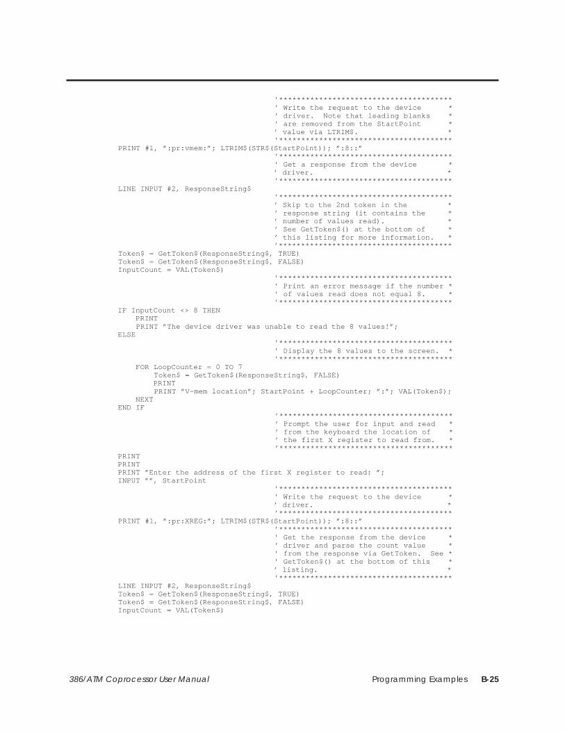
Programming Examples B-25386/ATM Coprocessor User Manual
’*************************************** ’ Write the request to the device * ’ driver. Note that leading blanks * ’ are removed from the StartPoint * ’ value via LTRIM$. * ’*************************************** PRINT #1, ”:pr:vmem:”; LTRIM$(STR$(StartPoint)); ”:8::” ’*************************************** ’ Get a response from the device * ’ driver. * ’*************************************** LINE INPUT #2, ResponseString$ ’*************************************** ’ Skip to the 2nd token in the * ’ response string (it contains the * ’ number of values read). * ’ See GetToken$() at the bottom of * ’ this listing for more information. * ’*************************************** Token$ = GetToken$(ResponseString$, TRUE) Token$ = GetToken$(ResponseString$, FALSE) InputCount = VAL(Token$) ’*************************************** ’ Print an error message if the number * ’ of values read does not equal 8. * ’*************************************** IF InputCount <> 8 THEN PRINT PRINT ”The device driver was unable to read the 8 values!”; ELSE ’*************************************** ’ Display the 8 values to the screen. * ’*************************************** FOR LoopCounter = 0 TO 7 Token$ = GetToken$(ResponseString$, FALSE) PRINT PRINT ”V–mem location”; StartPoint + LoopCounter; ”:”; VAL(Token$); NEXT END IF ’*************************************** ’ Prompt the user for input and read * ’ from the keyboard the location of * ’ the first X register to read from. * ’*************************************** PRINT PRINT PRINT ”Enter the address of the first X register to read: ”; INPUT ””, StartPoint ’*************************************** ’ Write the request to the device * ’ driver. * ’*************************************** PRINT #1, ”:pr:XREG:”; LTRIM$(STR$(StartPoint)); ”:8::” ’*************************************** ’ Get the response from the device * ’ driver and parse the count value * ’ from the response via GetToken. See * ’ GetToken$() at the bottom of this * ’ listing. * ’*************************************** LINE INPUT #2, ResponseString$ Token$ = GetToken$(ResponseString$, TRUE) Token$ = GetToken$(ResponseString$, FALSE) InputCount = VAL(Token$)
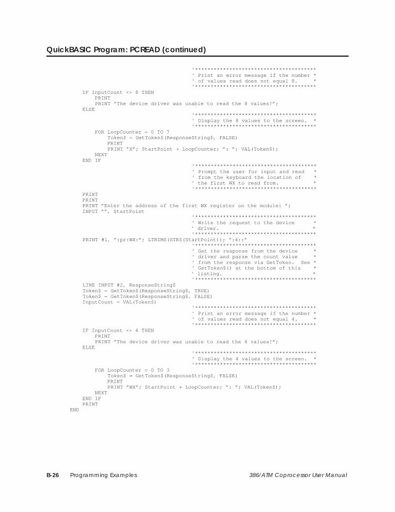
Programming ExamplesB-26 386/ATM Coprocessor User Manual
QuickBASIC Program: PCREAD (continued)
’*************************************** ’ Print an error message if the number * ’ of values read does not equal 8. * ’*************************************** IF InputCount <> 8 THEN PRINT PRINT ”The device driver was unable to read the 8 values!”; ELSE ’*************************************** ’ Display the 8 values to the screen. * ’*************************************** FOR LoopCounter = 0 TO 7 Token$ = GetToken$(ResponseString$, FALSE) PRINT PRINT ”X”; StartPoint + LoopCounter; ”: ”; VAL(Token$); NEXT END IF ’*************************************** ’ Prompt the user for input and read * ’ from the keyboard the location of * ’ the first WX to read from. * ’*************************************** PRINT PRINT PRINT ”Enter the address of the first WX register on the module: ”; INPUT ””, StartPoint ’*************************************** ’ Write the request to the device * ’ driver. * ’*************************************** PRINT #1, ”:pr:WX:”; LTRIM$(STR$(StartPoint)); ”:4::” ’*************************************** ’ Get the response from the device * ’ driver and parse the count value * ’ from the response via GetToken. See * ’ GetToken$() at the bottom of this * ’ listing. * ’*************************************** LINE INPUT #2, ResponseString$ Token$ = GetToken$(ResponseString$, TRUE) Token$ = GetToken$(ResponseString$, FALSE) InputCount = VAL(Token$) ’*************************************** ’ Print an error message if the number * ’ of values read does not equal 4. * ’*************************************** IF InputCount <> 4 THEN PRINT PRINT ”The device driver was unable to read the 4 values!”; ELSE ’*************************************** ’ Display the 4 values to the screen. * ’*************************************** FOR LoopCounter = 0 TO 3 Token$ = GetToken$(ResponseString$, FALSE) PRINT PRINT ”WX”; StartPoint + LoopCounter; ”: ”; VAL(Token$); NEXT END IF PRINTEND
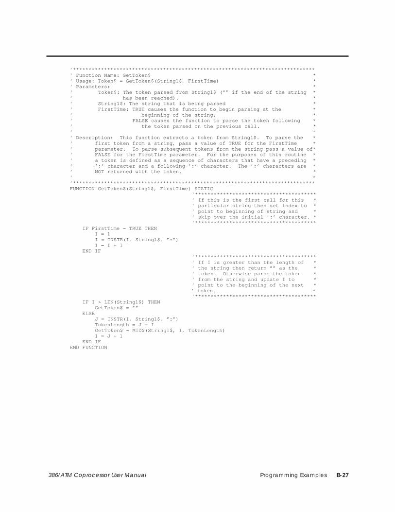
Programming Examples B-27386/ATM Coprocessor User Manual
’******************************************************************************’ Function Name: GetToken$ *’ Usage: Token$ = GetToken$(String1$, FirstTime) *’ Parameters: *’ Token$: The token parsed from String1$ (”” if the end of the string *’ has been reached). *’ String1$: The string that is being parsed *’ FirstTime: TRUE causes the function to begin parsing at the *’ beginning of the string. *’ FALSE causes the function to parse the token following *’ the token parsed on the previous call. *’ *’ Description: This function extracts a token from String1$. To parse the *’ first token from a string, pass a value of TRUE for the FirstTime *’ parameter. To parse subsequent tokens from the string pass a value of*’ FALSE for the FirstTime parameter. For the purposes of this routine *’ a token is defined as a sequence of characters that have a preceding *’ ’:’ character and a following ’:’ character. The ’:’ characters are *’ NOT returned with the token. *’ *’******************************************************************************FUNCTION GetToken$(String1$, FirstTime) STATIC ’*************************************** ’ If this is the first call for this * ’ particular string then set index to * ’ point to beginning of string and * ’ skip over the initial ’:’ character. * ’*************************************** IF FirstTime = TRUE THEN I = 1 I = INSTR(I, String1$, ”:”) I = I + 1 END IF ’*************************************** ’ If I is greater than the length of * ’ the string then return ”” as the * ’ token. Otherwise parse the token * ’ from the string and update I to * ’ point to the beginning of the next * ’ token. * ’*************************************** IF I > LEN(String1$) THEN GetToken$ = ”” ELSE J = INSTR(I, String1$, ”:”) TokenLength = J – I GetToken$ = MID$(String1$, I, TokenLength) I = J + 1 END IFEND FUNCTION
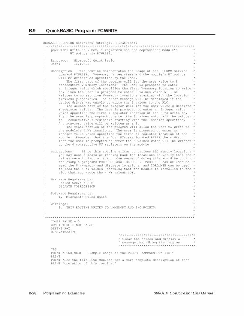
Programming ExamplesB-28 386/ATM Coprocessor User Manual
B.9 QuickBASIC Program: PCWRITE
DECLARE FUNCTION GetToken$ (String1$, FirstTime%)’******************************************************************************’ pcwr_msb: Write to V–mem, Y registers and the coprocessor module’s *’ WY points via PCWRITE. *’ *’ Language: Microsoft Quick Basic *’ Date: 11/12/90 *’ *’ Description: This routine demonstrates the usage of the PCCOMM service *’ command PCWRITE. V–memory, Y registers and the module’s WY points *’ will be written as specified by the user. *’ The first part of the program will let the user write to 8 *’ consecutive V–memory locations. The user is prompted to enter *’ an integer value which specifies the first V–memory location to write *’ to. Then the user is prompted to enter 8 values which will be *’ written to consecutive V–memory locations starting with the location *’ previously specified. An error message will be displayed if the *’ device driver was unable to write the 8 values to the PLC. *’ The second part of the program will let the user write 8 discrete *’ Y register values. The user is prompted to enter an integer value *’ which specifies the first Y register location of the 8 to write to. *’ Then the user is prompted to enter the 8 values which will be written *’ to 8 consecutive Y registers starting with the location specified. *’ Any non–zero value will be written as a 1. *’ The final section of the program will allow the user to write to *’ the module’s 4 WY locations. The user is prompted to enter an *’ integer value which specifies the first WY register location of the *’ module. Remember that the four WYs are located AFTER the 4 WXs. *’ Then the user is prompted to enter the 4 values which will be written *’ to the 4 consecutive WY registers on the module. *’ *’ Suggestions: Since this routine writes to various PLC memory locations *’ you may want a means of reading back the locations to verify that the *’ values were in fact written. One means of doing this would be to run *’ the example programs PCRD_MSB and IORD_MSB. PCRD_MSB can be used to *’ read the 8 v–memory and discrete locations, and IORD_MSB can be used *’ to read the 4 WY values (assuming that the module is installed in the *’ slot that you wrote the 4 WY values to). *’ *’ Hardware Requirements: *’ Series 500/505 PLC *’ 386/ATM COPROCESSOR *’ *’ Software Requirements: *’ 1. Microsoft Quick Basic *’ *’ Warnings: *’ 1. THIS ROUTINE WRITES TO V–MEMORY AND I/O POINTS. *’ *’ *’****************************************************************************** CONST FALSE = 0 CONST TRUE = NOT FALSE DEFINT A–Z DIM Values(7) ’*************************************** ’ Clear the screen and display a * ’ message describing the program. * ’*************************************** CLS PRINT ”PCWR_MSB: Example usage of the PCCOMM command PCWRITE.” PRINT PRINT ”See the file PCWR_MSB.bas for a more complete description of the” PRINT ”operation of this routine.”
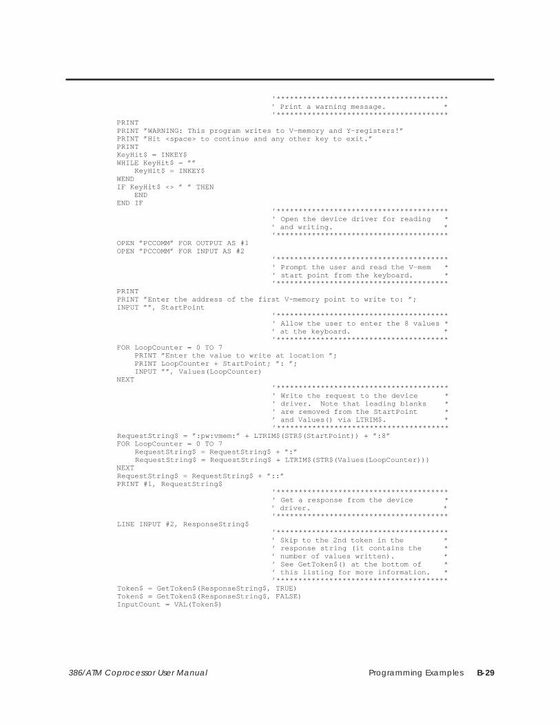
Programming Examples B-29386/ATM Coprocessor User Manual
’*************************************** ’ Print a warning message. * ’*************************************** PRINT PRINT ”WARNING: This program writes to V–memory and Y–registers!” PRINT ”Hit <space> to continue and any other key to exit.” PRINT KeyHit$ = INKEY$ WHILE KeyHit$ = ”” KeyHit$ = INKEY$ WEND IF KeyHit$ <> ” ” THEN END END IF ’*************************************** ’ Open the device driver for reading * ’ and writing. * ’*************************************** OPEN ”PCCOMM” FOR OUTPUT AS #1 OPEN ”PCCOMM” FOR INPUT AS #2 ’*************************************** ’ Prompt the user and read the V–mem * ’ start point from the keyboard. * ’*************************************** PRINT PRINT ”Enter the address of the first V–memory point to write to: ”; INPUT ””, StartPoint ’*************************************** ’ Allow the user to enter the 8 values * ’ at the keyboard. * ’*************************************** FOR LoopCounter = 0 TO 7 PRINT ”Enter the value to write at location ”; PRINT LoopCounter + StartPoint; ”: ”; INPUT ””, Values(LoopCounter) NEXT ’*************************************** ’ Write the request to the device * ’ driver. Note that leading blanks * ’ are removed from the StartPoint * ’ and Values() via LTRIM$. * ’*************************************** RequestString$ = ”:pw:vmem:” + LTRIM$(STR$(StartPoint)) + ”:8” FOR LoopCounter = 0 TO 7 RequestString$ = RequestString$ + ”:” RequestString$ = RequestString$ + LTRIM$(STR$(Values(LoopCounter))) NEXT RequestString$ = RequestString$ + ”::” PRINT #1, RequestString$ ’*************************************** ’ Get a response from the device * ’ driver. * ’*************************************** LINE INPUT #2, ResponseString$ ’*************************************** ’ Skip to the 2nd token in the * ’ response string (it contains the * ’ number of values written). * ’ See GetToken$() at the bottom of * ’ this listing for more information. * ’*************************************** Token$ = GetToken$(ResponseString$, TRUE) Token$ = GetToken$(ResponseString$, FALSE) InputCount = VAL(Token$)

Programming ExamplesB-30 386/ATM Coprocessor User Manual
QuickBASIC Program: PCWRITE (continued)
’*************************************** ’ Print an error message if the number * ’ of values written does not equal 8. * ’*************************************** IF InputCount <> 8 THEN PRINT PRINT ”The device driver was unable to write the 8 values!”; PRINT END IF ’*************************************** ’ Prompt the user for input and read * ’ from the keyboard the location of * ’ the first Y register to write to. * ’*************************************** PRINT PRINT ”Enter the address of the first Y register to write to: ”; INPUT ””, StartPoint ’*************************************** ’ Allow the user to enter the 8 values * ’ at the keyboard. Any non–zero value * ’ is written as a 1. * ’*************************************** FOR LoopCounter = 0 TO 7 PRINT ”Enter the value to write at Y”; PRINT LoopCounter + StartPoint; ”: ”; INPUT ””, Values(LoopCounter) NEXT ’*************************************** ’ Write the request to the device * ’ driver. Note that leading blanks * ’ are removed from the StartPoint * ’ and Values() via LTRIM$. * ’*************************************** RequestString$ = ”:pw:YREG:” + LTRIM$(STR$(StartPoint)) + ”:8” FOR LoopCounter = 0 TO 7 RequestString$ = RequestString$ + ”:” RequestString$ = RequestString$ + LTRIM$(STR$(Values(LoopCounter))) NEXT RequestString$ = RequestString$ + ”::” PRINT #1, RequestString$ ’*************************************** ’ Get the response from the device * ’ driver and parse the count value * ’ from the response via GetToken. See * ’ GetToken$() at the bottom of this * ’ listing. * ’*************************************** LINE INPUT #2, ResponseString$ Token$ = GetToken$(ResponseString$, TRUE) Token$ = GetToken$(ResponseString$, FALSE) InputCount = VAL(Token$) ’*************************************** ’ Print an error message if the number * ’ of values written does not equal 8. * ’*************************************** IF InputCount <> 8 THEN PRINT PRINT ”The device driver was unable to write the 8 values!”; PRINT END IF ’*************************************** ’ Prompt the user for input and read * ’ from the keyboard the location of * ’ the first WY to write to. * ’*************************************** PRINT PRINT ”Enter the address of the first WY register on the module: ”; INPUT ””, StartPoint
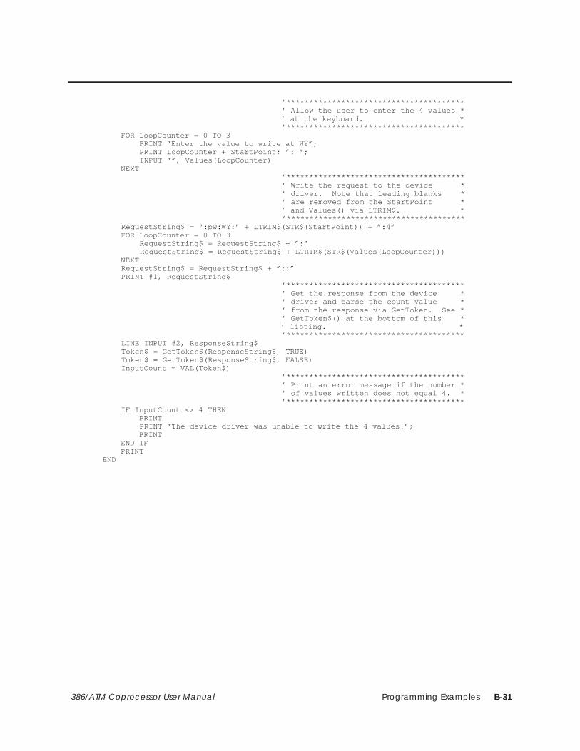
Programming Examples B-31386/ATM Coprocessor User Manual
’*************************************** ’ Allow the user to enter the 4 values * ’ at the keyboard. * ’*************************************** FOR LoopCounter = 0 TO 3 PRINT ”Enter the value to write at WY”; PRINT LoopCounter + StartPoint; ”: ”; INPUT ””, Values(LoopCounter) NEXT ’*************************************** ’ Write the request to the device * ’ driver. Note that leading blanks * ’ are removed from the StartPoint * ’ and Values() via LTRIM$. * ’*************************************** RequestString$ = ”:pw:WY:” + LTRIM$(STR$(StartPoint)) + ”:4” FOR LoopCounter = 0 TO 3 RequestString$ = RequestString$ + ”:” RequestString$ = RequestString$ + LTRIM$(STR$(Values(LoopCounter))) NEXT RequestString$ = RequestString$ + ”::” PRINT #1, RequestString$ ’*************************************** ’ Get the response from the device * ’ driver and parse the count value * ’ from the response via GetToken. See * ’ GetToken$() at the bottom of this * ’ listing. * ’*************************************** LINE INPUT #2, ResponseString$ Token$ = GetToken$(ResponseString$, TRUE) Token$ = GetToken$(ResponseString$, FALSE) InputCount = VAL(Token$) ’*************************************** ’ Print an error message if the number * ’ of values written does not equal 4. * ’*************************************** IF InputCount <> 4 THEN PRINT PRINT ”The device driver was unable to write the 4 values!”; PRINT END IF PRINTEND

Programming ExamplesB-32 386/ATM Coprocessor User Manual
QuickBASIC Program: PCWRITE (continued)
’******************************************************************************’ Function Name: GetToken$ *’ Usage: Token$ = GetToken$(String1$, FirstTime) *’ Parameters: *’ Token$: The token parsed from String1$ (”” if the end of the string *’ has been reached). *’ String1$: The string that is being parsed *’ FirstTime: TRUE causes the function to begin parsing at the *’ beginning of the string. *’ FALSE causes the function to parse the token following *’ the token parsed on the previous call. *’ *’ Description: This function extracts a token from String1$. To parse the *’ first token from a string, pass a value of TRUE for the FirstTime *’ parameter. To parse subsequent tokens from the string pass a value of*’ FALSE for the FirstTime parameter. For the purposes of this routine *’ a token is defined as a sequence of characters that have a preceding *’ ’:’ character and a following ’:’ character. The ’:’ characters are *’ NOT returned with the token. *’ *’******************************************************************************FUNCTION GetToken$ (String1$, FirstTime) STATIC ’*************************************** ’ If this is the first call for this * ’ particular string then set index to * ’ point to beginning of string and * ’ skip over the initial ’:’ character. * ’*************************************** IF FirstTime = TRUE THEN I = 1 I = INSTR(I, String1$, ”:”) I = I + 1 END IF ’*************************************** ’ If I is greater than the length of * ’ the string then return ”” as the * ’ token. Otherwise parse the token * ’ from the string and update I to * ’ point to the beginning of the next * ’ token. * ’*************************************** IF I > LEN(String1$) THEN GetToken$ = ”” ELSE J = INSTR(I, String1$, ”:”) TokenLength = J – I GetToken$ = MID$(String1$, I, TokenLength) I = J + 1 END IFEND FUNCTION

Programming Examples B-33386/ATM Coprocessor User Manual
B.10 GW-BASIC Program: IOREAD
1 ’***************************************************************************2 ’ iord_gw: Read the coprocessor module’s WY values. *3 ’ *5 ’ Language: Microsoft GW–Basic *6 ’ Date: 11/13/90 *7 ’ *8 ’ Description: This routine demonstrates the usage of the PCCOMM service *9 ’ command IOREAD. The 4 local WY points will be read and displayed *10 ’ to the screen. *11 ’ *12 ’ Suggestions: You may want to run PCWR_GW prior to execution of this *13 ’ program to verify that real values are being read by this routine. *14 ’ The last part of PCWR_GW allows the user to write to the WY values. *15 ’ *16 ’ Hardware Requirements: *17 ’ Series 500/505 PLC *18 ’ 386/ATM COPROCESSOR *19 ’ *20 ’ Software Requirements: *21 ’ 1. Microsoft GW–BASIC *22 ’ *23 ’ Warnings: *24 ’ *25 ’ *26 ’***************************************************************************40 DEFINT A–Z50 FALSE = 060 TRUE = NOT FALSE70 DIM VALUES(3)90 ’***************************************110 ’ Clear the screen and display a *130 ’ message describing the program. *140 ’***************************************150 CLS160 PRINT ”IORD_GW: Example usage of the PCCOMM command IOREAD to read”;170 PRINT ” from the module’s”180 PRINT ” WY points.”190 PRINT200 PRINT ”See the file IORD_GW.bas for a more complete description of the”210 PRINT ”operation of this routine.”220 PRINT230 ’***************************************240 ’ Open the device driver for reading *250 ’ and writing. *260 ’***************************************270 OPEN ”PCCOMM” FOR OUTPUT AS #1280 OPEN ”PCCOMM” FOR INPUT AS #2290 ’***************************************300 ’ Write the request to the device *310 ’ driver. *320 ’***************************************330 PRINT #1, ”:IR:5:4::”340 ’***************************************350 ’ Get the response from the device *360 ’ driver. *370 ’***************************************380 LINE INPUT #2, RESPONSESTRING$390 ’***************************************400 ’ Skip to the 2nd token in the response*410 ’ string (it contains the number of *420 ’ values read). See GetToken *425 ’ subroutine (line 700). *430 ’***************************************440 STRING1$ = RESPONSESTRING$450 FIRSTTIME = TRUE460 GOSUB 700470 FIRSTTIME = FALSE480 GOSUB 700
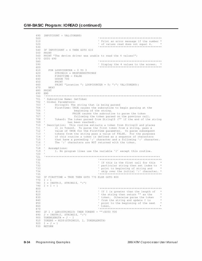
Programming ExamplesB-34 386/ATM Coprocessor User Manual
GW-BASIC Program: IOREAD (continued)
490 INPUTCOUNT = VAL(TOKEN$)500 ’***************************************510 ’ Print an error message if the number *520 ’ of values read does not equal 4. *530 ’***************************************540 IF INPUTCOUNT = 4 THEN GOTO 610550 PRINT560 PRINT ”The device driver was unable to read the 4 values!”;570 GOTO 690580 ’***************************************590 ’ Display the 4 values to the screen. *600 ’***************************************610 FOR LOOPCOUNTER = 0 TO 3620 STRING1$ = RESPONSESTRING$630 FIRSTTIME = FALSE640 GOSUB 700650 PRINT660 PRINT ”Location ”; LOOPCOUNTER + 5; ”:”; VAL(TOKEN$);670 NEXT680 PRINT690 END700 ’*************************************************************************701 ’ Subroutine Name: GetToken702 ’ Global Parameters:703 ’ String1$: The string that is being parsed704 ’ FirstTime: TRUE causes the subroutine to begin parsing at the705 ’ beginning of the string.706 ’ FALSE causes the subroutine to parse the token707 ’ following the token parsed on the previous call.708 ’ Token$: The token parsed from String1$ (”” if the end of the string709 ’ has been reached).710 ’ Description: This routine extracts a token from String1$ and places711 ’ it in Token$. To parse the first token from a string, pass a712 ’ value of TRUE for the FirstTime parameter. To parse subsequent713 ’ tokens from the string pass a value of FALSE. For the purposes714 ’ of this routine a token is defined as a sequence of characters715 ’ that have a preceding ’:’ character and a following ’:’ character.716 ’ The ’:’ characters are NOT returned with the token.717 ’718 ’ Assumptions:719 ’ 1. No program lines use the variable ’I’ except this routine.720 ’721 ’************************************************************************730 ’***************************************731 ’ If this is the first call for this *732 ’ particular string then set index to *733 ’ point to beginning of string and *734 ’ skip over the initial ’:’ character. *735 ’***************************************760 IF FIRSTTIME = TRUE THEN GOTO 770 ELSE GOTO 800770 I = 1780 I = INSTR(I, STRING1$, ”:”)790 I = I + 1800 ’***************************************810 ’ If I is greater than the length of *820 ’ the string then return ”” as the *830 ’ token. Otherwise parse the token *840 ’ from the string and update I to *850 ’ point to the beginning of the next *860 ’ token. *870 ’***************************************880 IF I > LEN(STRING1$) THEN TOKEN$ = ””:GOTO 930890 J = INSTR(I, STRING1$, ”:”)900 TOKENLENGTH = J – I910 TOKEN$ = MID$(STRING1$, I, TOKENLENGTH)920 I = J + 1930 RETURN

Programming Examples B-35386/ATM Coprocessor User Manual
B.11 GW-BASIC Program: IOWRITE
1 ’***************************************************************************2 ’ iowr_gw: Write to the coprocessor module’s WX values. *3 ’ *5 ’ Language: Microsoft GW–Basic *6 ’ Date: 11/13/90 *7 ’ *8 ’ Description: This routine demonstrates the usage of the PCCOMM service *9 ’ command IOWRITE. The 4 local WX points will be written as specified *10 ’ by the user. *11 ’ *12 ’ Suggestions: You may want to run PCRD_GW after this program to verify *13 ’ that the values were written correctly by this routine. The last *14 ’ part of PCRD_GW allows the user to read the WX values. *15 ’ *16 ’ Hardware Requirements: *17 ’ Series 500/505 PLC *18 ’ 386/ATM COPROCESSOR *19 ’ *20 ’ Software Requirements: *21 ’ 1. Microsoft GW–BASIC *22 ’ *23 ’ Warnings: *24 ’ *25 ’ *26 ’***************************************************************************100 DEFINT A–Z110 FALSE = 0120 TRUE = NOT FALSE130 DIM Values(3)140 ’***************************************150 ’ Clear the screen and display a *160 ’ message describing the program. *170 ’***************************************180 CLS190 PRINT ”IOWR_GW: Example usage of the PCCOMM command IOWRITE to write”;200 PRINT ” to the module’s”210 PRINT ” WX points.”220 PRINT230 PRINT ”See the file IOWR_GW.bas for a more complete description of the”240 PRINT ”operation of this routine.”250 PRINT260 ’***************************************270 ’ Open the device driver for reading *280 ’ and writing. *290 ’***************************************300 OPEN ”PCCOMM” FOR OUTPUT AS #1310 OPEN ”PCCOMM” FOR INPUT AS #2320 ’***************************************330 ’ Prompt the user and accept entry of *340 ’ the 4 values that will be written to *350 ’ the WX points. *380 ’***************************************390 FOR LoopCounter = 0 TO 3400 PRINT ”Enter the value to write at location ”;410 PRINT LoopCounter + 1; ”: ”;420 INPUT ””, Values(LoopCounter)430 NEXT440 ’***************************************450 ’ Write the request to the device *460 ’ driver. Note that leading blanks *470 ’ are removed from Values() via *480 ’ RemoveBlanks subroutine (line 2000). *490 ’***************************************500 RequestString$ = ”:iw:1:4”510 FOR LoopCounter = 0 TO 3520 RequestString$ = RequestString$ + ”:”525 String2$ = STR$(Values(LoopCounter))527 GOSUB 2000
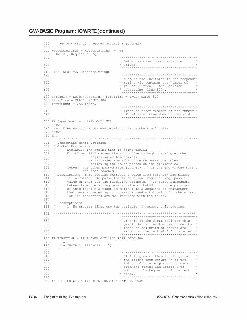
Programming ExamplesB-36 386/ATM Coprocessor User Manual
GW-BASIC Program: IOWRITE (continued)
530 RequestString$ = RequestString$ + String2$540 NEXT550 RequestString$ = RequestString$ + ”::”560 PRINT #1, RequestString$570 ’***************************************580 ’ Get a response from the device *590 ’ driver. *600 ’***************************************610 LINE INPUT #2, ResponseString$620 ’***************************************630 ’ Skip to the 2nd token in the response*640 ’ string (it contains the number of *650 ’ values written). See GetToken *655 ’ subroutine (line 800). *660 ’***************************************670 String1$ = ResponseString$: FirstTime = TRUE: GOSUB 800680 FirstTime = FALSE: GOSUB 800690 InputCount = VAL(Token$)700 ’***************************************710 ’ Print an error message if the number *720 ’ of values written does not equal 4. *730 ’***************************************740 IF InputCount = 4 THEN GOTO 770750 PRINT760 PRINT ”The device driver was unable to write the 4 values!”;770 PRINT780 END800 ’*************************************************************************801 ’ Subroutine Name: GetToken802 ’ Global Parameters:803 ’ String1$: The string that is being parsed804 ’ FirstTime: TRUE causes the subroutine to begin parsing at the805 ’ beginning of the string.806 ’ FALSE causes the subroutine to parse the token807 ’ following the token parsed on the previous call.808 ’ Token$: The token parsed from String1$ (”” if the end of the string809 ’ has been reached).810 ’ Description: This routine extracts a token from String1$ and places811 ’ it in Token$. To parse the first token from a string, pass a812 ’ value of TRUE for the FirstTime parameter. To parse subsequent813 ’ tokens from the string pass a value of FALSE. For the purposes814 ’ of this routine a token is defined as a sequence of characters815 ’ that have a preceding ’:’ character and a following ’:’ character.816 ’ The ’:’ characters are NOT returned with the token.817 ’818 ’ Assumptions:819 ’ 1. No program lines use the variable ’I’ except this routine.820 ’821 ’************************************************************************829 ’***************************************830 ’ If this is the first call for this *835 ’ particular string then set index to *840 ’ point to beginning of string and *845 ’ skip over the initial ’:’ character. *850 ’***************************************860 IF FIRSTTIME = TRUE THEN GOTO 870 ELSE GOTO 900870 I = 1880 I = INSTR(I, STRING1$, ”:”)890 I = I + 1900 ’***************************************910 ’ If I is greater than the length of *920 ’ the string then return ”” as the *930 ’ token. Otherwise parse the token *940 ’ from the string and update I to *950 ’ point to the beginning of the next *960 ’ token. *970 ’***************************************980 IF I > LEN(STRING1$) THEN TOKEN$ = ””:GOTO 1030

Programming Examples B-37386/ATM Coprocessor User Manual
990 J = INSTR(I, STRING1$, ”:”)1000 TOKENLENGTH = J – I1010 TOKEN$ = MID$(STRING1$, I, TOKENLENGTH)1020 I = J + 11030 RETURN2000 ’*************************************************************************2001 ’ Subroutine Name: RemoveBlanks2002 ’ Global Parameters:2003 ’ String2$: The string that leading blanks are removed from2004 ’ Description: This routine removes leading blanks from String2$.2005 ’2006 ’ Assumptions:2007 ’ 1. No program lines use the variable ’I2’ except this routine.2008 ’2009 ’*************************************************************************2030 I2 = LEN(String2$)2040 FirstChar$ = MID$(String2$, 1, 1)2050 WHILE FirstChar$ = ” ”2060 I2 = I2 – 12070 String2$ = RIGHT$(String2$, I2)2085 FirstChar$ = MID$(String2$, 1, 1)2090 WEND2100 RETURN
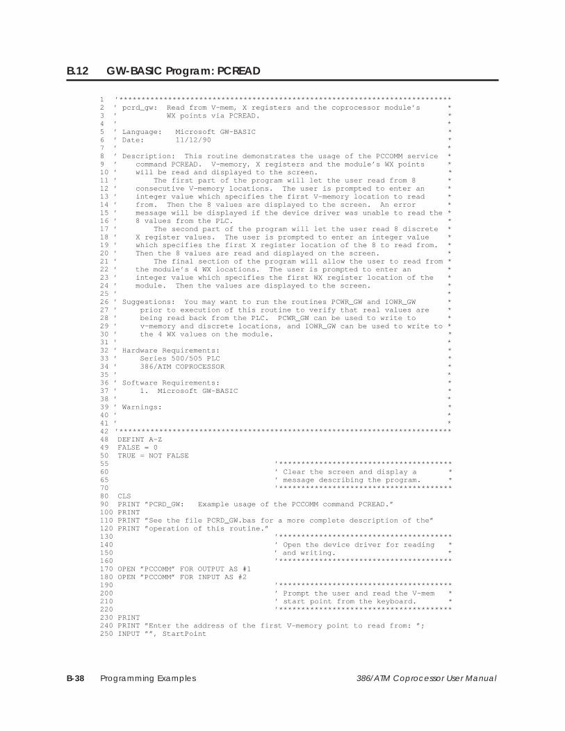
Programming ExamplesB-38 386/ATM Coprocessor User Manual
B.12 GW-BASIC Program: PCREAD
1 ’***************************************************************************2 ’ pcrd_gw: Read from V–mem, X registers and the coprocessor module’s *3 ’ WX points via PCREAD. *4 ’ *5 ’ Language: Microsoft GW–BASIC *6 ’ Date: 11/12/90 *7 ’ *8 ’ Description: This routine demonstrates the usage of the PCCOMM service *9 ’ command PCREAD. V–memory, X registers and the module’s WX points *10 ’ will be read and displayed to the screen. *11 ’ The first part of the program will let the user read from 8 *12 ’ consecutive V–memory locations. The user is prompted to enter an *13 ’ integer value which specifies the first V–memory location to read *14 ’ from. Then the 8 values are displayed to the screen. An error *15 ’ message will be displayed if the device driver was unable to read the *16 ’ 8 values from the PLC. *17 ’ The second part of the program will let the user read 8 discrete *18 ’ X register values. The user is prompted to enter an integer value *19 ’ which specifies the first X register location of the 8 to read from. *20 ’ Then the 8 values are read and displayed on the screen. *21 ’ The final section of the program will allow the user to read from *22 ’ the module’s 4 WX locations. The user is prompted to enter an *23 ’ integer value which specifies the first WX register location of the *24 ’ module. Then the values are displayed to the screen. *25 ’ *26 ’ Suggestions: You may want to run the routines PCWR_GW and IOWR_GW *27 ’ prior to execution of this routine to verify that real values are *28 ’ being read back from the PLC. PCWR_GW can be used to write to *29 ’ v–memory and discrete locations, and IOWR_GW can be used to write to *30 ’ the 4 WX values on the module. *31 ’ *32 ’ Hardware Requirements: *33 ’ Series 500/505 PLC *34 ’ 386/ATM COPROCESSOR *35 ’ *36 ’ Software Requirements: *37 ’ 1. Microsoft GW–BASIC *38 ’ *39 ’ Warnings: *40 ’ *41 ’ *42 ’***************************************************************************48 DEFINT A–Z49 FALSE = 050 TRUE = NOT FALSE55 ’***************************************60 ’ Clear the screen and display a *65 ’ message describing the program. *70 ’***************************************80 CLS90 PRINT ”PCRD_GW: Example usage of the PCCOMM command PCREAD.”100 PRINT110 PRINT ”See the file PCRD_GW.bas for a more complete description of the”120 PRINT ”operation of this routine.”130 ’***************************************140 ’ Open the device driver for reading *150 ’ and writing. *160 ’***************************************170 OPEN ”PCCOMM” FOR OUTPUT AS #1180 OPEN ”PCCOMM” FOR INPUT AS #2190 ’***************************************200 ’ Prompt the user and read the V–mem *210 ’ start point from the keyboard. *220 ’***************************************230 PRINT240 PRINT ”Enter the address of the first V–memory point to read from: ”;250 INPUT ””, StartPoint
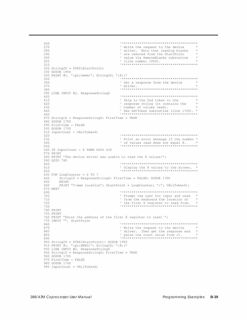
Programming Examples B-39386/ATM Coprocessor User Manual
260 ’***************************************270 ’ Write the request to the device *280 ’ driver. Note that leading blanks *290 ’ are removed from the StartPoint *300 ’ value via RemoveBlanks subroutine *305 ’ (line number 1950). *310 ’***************************************320 String2$ = STR$(StartPoint)330 GOSUB 1950340 PRINT #1, ”:pr:vmem:”; String2$; ”:8::”350 ’***************************************360 ’ Get a response from the device *370 ’ driver. *380 ’***************************************390 LINE INPUT #2, ResponseString$400 ’***************************************410 ’ Skip to the 2nd token in the *420 ’ response string (it contains the *430 ’ number of values read). *440 ’ See GetToken subroutine (line 1700). *460 ’***************************************470 String1$ = ResponseString$: FirstTime = TRUE480 GOSUB 1700490 FirstTime = FALSE500 GOSUB 1700510 InputCount = VAL(Token$)520 ’***************************************530 ’ Print an error message if the number *540 ’ of values read does not equal 8. *550 ’***************************************560 IF InputCount = 8 THEN GOTO 630570 PRINT580 PRINT ”The device driver was unable to read the 8 values!”;590 GOTO 740600 ’***************************************610 ’ Display the 8 values to the screen. *620 ’***************************************630 FOR LoopCounter = 0 TO 7640 String1$ = ResponseString$: FirstTime = FALSE: GOSUB 1700650 PRINT660 PRINT ”V–mem location”; StartPoint + LoopCounter; ”:”; VAL(Token$);670 NEXT690 ’***************************************700 ’ Prompt the user for input and read *710 ’ from the keyboard the location of *720 ’ the first X register to read from. *730 ’***************************************740 PRINT750 PRINT760 PRINT ”Enter the address of the first X register to read: ”;770 INPUT ””, StartPoint860 ’***************************************870 ’ Write the request to the device *880 ’ driver. Then get the response and *885 ’ parse the count value from it. *890 ’***************************************900 String2$ = STR$(StartPoint): GOSUB 1950910 PRINT #1, ”:pr:XREG:”; String2$; ”:8::”930 LINE INPUT #2, ResponseString$950 String1$ = ResponseString$: FirstTime = TRUE960 GOSUB 1700970 FirstTime = FALSE980 GOSUB 1700990 InputCount = VAL(Token$)

Programming ExamplesB-40 386/ATM Coprocessor User Manual
GW-BASIC Program: PCREAD (continued)
1000 ’***************************************1010 ’ Print an error message if the number *1020 ’ of values read does not equal 8. *1030 ’***************************************1040 IF InputCount = 8 THEN GOTO 11101050 PRINT1060 PRINT ”The device driver was unable to read the 8 values!”;1070 GOTO 11601080 ’***************************************1090 ’ Display the 8 values to the screen. *1100 ’***************************************1110 FOR LoopCounter = 0 TO 71120 String1$ = ResponseString$: FirstTime = FALSE: GOSUB 17001130 PRINT1140 PRINT ”X”; StartPoint + LoopCounter; ”: ”; VAL(Token$);1150 NEXT1160 ’***************************************1170 ’ Prompt the user for input and read *1180 ’ from the keyboard the location of *1190 ’ the first WX to read from. *1200 ’***************************************1210 PRINT1220 PRINT1230 PRINT ”Enter the address of the first WX register on the module: ”;1240 INPUT ””, StartPoint1330 ’***************************************1340 ’ Write the request to the device *1350 ’ driver. Then get response and parse *1355 ’ the count value from it. *1360 ’***************************************1370 String2$ = STR$(StartPoint)1380 GOSUB 19501390 PRINT #1, ”:pr:WX:”; String2$; ”:4::”1410 LINE INPUT #2, ResponseString$1430 String1$ = ResponseString$: FirstTime = TRUE1440 GOSUB 17001450 FirstTime = FALSE1460 GOSUB 17001470 InputCount = VAL(Token$)1480 ’***************************************1490 ’ Print an error message if the number *1500 ’ of values read does not equal 4. *1510 ’***************************************1520 IF InputCount = 4 THEN GOTO 15901530 PRINT1540 PRINT ”The device driver was unable to read the 4 values!”;1550 GOTO 16501560 ’***************************************1570 ’ Display the 4 values to the screen. *1580 ’***************************************1590 FOR LoopCounter = 0 TO 31600 String1$ = ResponseString$: FirstTime = FALSE: GOSUB 17001610 PRINT1620 PRINT ”WX”; StartPoint + LoopCounter; ”: ”; VAL(Token$);1630 NEXT1650 PRINT1670 END

Programming Examples B-41386/ATM Coprocessor User Manual
1700 ’*************************************************************************1701 ’ Subroutine Name: GetToken1702 ’ Global Parameters:1703 ’ String1$: The string that is being parsed1704 ’ FirstTime: TRUE causes the subroutine to begin parsing at the1705 ’ beginning of the string.1706 ’ FALSE causes the subroutine to parse the token1707 ’ following the token parsed on the previous call.1708 ’ Token$: The token parsed from String1$ (”” if the end of the string1709 ’ has been reached).1710 ’ Description: This routine extracts a token from String1$ and places1711 ’ it in Token$. To parse the first token from a string, pass a1712 ’ value of TRUE for the FirstTime parameter. To parse subsequent1713 ’ tokens from the string pass a value of FALSE. For the purposes1714 ’ of this routine a token is defined as a sequence of characters1715 ’ that have a preceding ’:’ character and a following ’:’ character.1716 ’ The ’:’ characters are NOT returned with the token.1717 ’1718 ’ Assumptions:1719 ’ 1. No program lines use the variable ’I’ except this routine.1720 ’1721 ’************************************************************************1730 ’***************************************1731 ’ If this is the first call for this *1732 ’ particular string then set index to *1740 ’ point to beginning of string and *1750 ’ skip over the initial ’:’ character. *1760 ’***************************************1770 IF FIRSTTIME = TRUE THEN GOTO 1780 ELSE GOTO 18901780 I = 11790 I = INSTR(I, STRING1$, ”:”)1800 I = I + 11810 ’***************************************1820 ’ If I is greater than the length of *1830 ’ the string then return ”” as the *1840 ’ token. Otherwise parse the token *1850 ’ from the string and update I to *1860 ’ point to the beginning of the next *1870 ’ token. *1880 ’***************************************1890 IF I > LEN(STRING1$) THEN TOKEN$ = ””:GOTO 19401900 J = INSTR(I, STRING1$, ”:”)1910 TOKENLENGTH = J – I1920 TOKEN$ = MID$(STRING1$, I, TOKENLENGTH)1930 I = J + 11940 RETURN1950 ’*************************************************************************1951 ’ Subroutine Name: RemoveBlanks1952 ’ Global Parameters:1953 ’ String2$: The string that leading blanks are removed from1954 ’ Description: This routine removes leading blanks from String2$.1955 ’1956 ’ Assumptions:1957 ’ 1. No program lines use the variable ’I2’ except this routine.1958 ’1959 ’*************************************************************************1970 I2 = LEN(String2$)1980 FirstChar$ = MID$(String2$, 1, 1)1990 WHILE FirstChar$ = ” ”2000 I2 = I2 – 12010 String2$ = RIGHT$(String2$, I2)2020 FirstChar$ = MID$(String2$, 1, 1)2030 WEND2040 RETURN

Programming ExamplesB-42 386/ATM Coprocessor User Manual
B.13 GW-BASIC Program: PCWRITE
1 ’***************************************************************************2 ’ pcwr_gw: Write to V–mem, Y registers and the coprocessor module’s *3 ’ WY points via PCWRITE. *4 ’ *5 ’ Language: Microsoft GW–BASIC *6 ’ Date: 11/12/90 *7 ’ *8 ’ Description: This routine demonstrates the usage of the PCCOMM service *9 ’ command PCWRITE. V–memory, Y registers and the module’s WY points *10 ’ will be written as specified by the user. *11 ’ The first part of the program will let the user write to 8 *12 ’ consecutive V–memory locations. The user is prompted to enter *13 ’ an integer value which specifies the first V–memory location to write *14 ’ to. Then the user is prompted to enter 8 values which will be *15 ’ written to consecutive V–memory locations starting with the location *16 ’ previously specified. An error message will be displayed if the *17 ’ device driver was unable to write the 8 values to the PLC. *18 ’ The second part of the program will let the user write 8 discrete *19 ’ Y register values. The user is prompted to enter an integer value *20 ’ which specifies the first Y register location of the 8 to write to. *21 ’ Then the user is prompted to enter the 8 values which will be written *22 ’ to 8 consecutive Y registers starting with the location specified. *23 ’ Any non–zero value will be written as a 1. *24 ’ The final section of the program will allow the user to write to *25 ’ the module’s 4 WY locations. The user is prompted to enter an *26 ’ integer value which specifies the first WY register location of the *27 ’ module. Remember that the four WYs are located AFTER the 4 WXs. *28 ’ Then the user is prompted to enter the 4 values which will be written *29 ’ to the 4 consecutive WY registers on the module. *30 ’ *31 ’ Suggestions: Since this routine writes to various PLC memory locations*32 ’ you may want a means of reading back the locations to verify that the*33 ’ values were in fact written. One means of doing this would be to run*34 ’ the example programs PCRD_GW and IORD_GW. PCRD_GW can be used to *35 ’ read the 8 v–memory and discrete locations, and IORD_GW can be used *36 ’ to read the 4 WY values (assuming that the module is installed in the*37 ’ slot that you wrote the 4 WY values to). *38 ’ *39 ’ Hardware Requirements: *40 ’ Series 500/505 PLC *41 ’ 386/ATM COPROCESSOR *42 ’ *43 ’ Software Requirements: *44 ’ 1. Microsoft GW–BASIC *45 ’ *46 ’ Warnings: *47 ’ 1. THIS ROUTINE WRITES TO V–MEMORY AND I/O POINTS. *48 ’ *49 ’ *50 ’***************************************************************************54 DEFINT A–Z55 FALSE = 060 TRUE = NOT FALSE65 DIM Values(7)70 ’***************************************75 ’ Clear the screen and display a *80 ’ message describing the program. *85 ’***************************************90 CLS100 PRINT ”PCWR_GW: Example usage of the PCCOMM command PCWRITE.”110 PRINT120 PRINT ”See the file PCWR_GW.bas for a more complete description of the”130 PRINT ”operation of this routine.”131 ’***************************************132 ’ Print a warning message. *133 ’***************************************134 PRINT135 PRINT ”WARNING: This program writes to V–memory and Y–registers!”

Programming Examples B-43386/ATM Coprocessor User Manual
136 PRINT ”Hit <space> to continue and any other key to exit.”137 PRINT138 KeyHit$ = INKEY$139 WHILE KeyHit$ = ””140 KeyHit$ = INKEY$141 WEND142 IF KeyHit$ <> ” ” THEN END177 ’***************************************178 ’ Open the device driver for reading *179 ’ and writing. *180 ’***************************************190 OPEN ”PCCOMM” FOR OUTPUT AS #1200 OPEN ”PCCOMM” FOR INPUT AS #2220 ’***************************************230 ’ Prompt the user and read the V–mem *240 ’ start point from the keyboard. *250 ’***************************************260 PRINT270 PRINT ”Enter the address of the first V–memory point to write to: ”;280 INPUT ””, StartPoint300 ’***************************************310 ’ Allow the user to enter the 8 values *320 ’ at the keyboard. *350 ’***************************************360 FOR LoopCounter = 0 TO 7370 PRINT ”Enter the value to write at location ”;380 PRINT LoopCounter + StartPoint; ”: ”;390 INPUT ””, Values(LoopCounter)400 NEXT420 ’***************************************430 ’ Write the request to the device *440 ’ driver. Note that leading blanks *450 ’ are removed from the StartPoint *460 ’ and Values() via RemoveBlanks *465 ’ subroutine (line number 2950). *470 ’***************************************475 String2$ = STR$(StartPoint): GOSUB 2950480 RequestString$ = ”:pw:vmem:” + String2$ + ”:8”490 FOR LoopCounter = 0 TO 7500 RequestString$ = RequestString$ + ”:”505 String2$ = STR$(Values(LoopCounter)): GOSUB 2950510 RequestString$ = RequestString$ + String2$520 NEXT530 RequestString$ = RequestString$ + ”::”540 PRINT #1, RequestString$560 ’***************************************570 ’ Get a response from the device *580 ’ driver. *590 ’***************************************600 LINE INPUT #2, ResponseString$620 ’***************************************630 ’ Skip to the 2nd token in the *640 ’ response string (it contains the *650 ’ number of values written). See *660 ’ GetToken subroutine (line 2700) *680 ’***************************************690 String1$ = ResponseString$: FirstTime = TRUE: GOSUB 2700700 FirstTime = FALSE: GOSUB 2700710 InputCount = VAL(Token$)730 ’***************************************740 ’ Print an error message if the number *750 ’ of values written does not equal 8. *760 ’***************************************770 IF InputCount = 8 THEN GOTO 880780 PRINT790 PRINT ”The device driver was unable to write the 8 values!”;800 PRINT
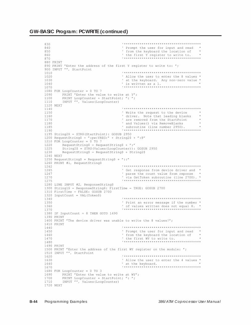
Programming ExamplesB-44 386/ATM Coprocessor User Manual
GW-BASIC Program: PCWRITE (continued)
830 ’***************************************840 ’ Prompt the user for input and read *850 ’ from the keyboard the location of *860 ’ the first Y register to write to. *870 ’***************************************880 PRINT890 PRINT ”Enter the address of the first Y register to write to: ”;900 INPUT ””, StartPoint1010 ’***************************************1020 ’ Allow the user to enter the 8 values *1030 ’ at the keyboard. Any non–zero value *1040 ’ is written as a 1. *1070 ’***************************************1080 FOR LoopCounter = 0 TO 71090 PRINT ”Enter the value to write at Y”;1100 PRINT LoopCounter + StartPoint; ”: ”;1110 INPUT ””, Values(LoopCounter)1120 NEXT1140 ’***************************************1150 ’ Write the request to the device *1160 ’ driver. Note that leading blanks *1170 ’ are removed from the StartPoint *1180 ’ and Values() via RemoveBlanks *1185 ’ subroutine (line number 2950). *1190 ’***************************************1195 String2$ = STR$(StartPoint): GOSUB 29501200 RequestString$ = ”:pw:YREG:” + String2$ + ”:8”1210 FOR LoopCounter = 0 TO 71220 RequestString$ = RequestString$ + ”:”1225 String2$ = STR$(Values(LoopCounter)): GOSUB 29501230 RequestString$ = RequestString$ + String2$1240 NEXT1250 RequestString$ = RequestString$ + ”::”1260 PRINT #1, RequestString$1262 ’***************************************1265 ’ Get response from device driver and *1267 ’ parse the count value from reponse *1270 ’ via GetToken subroutine (line 2700). *1275 ’***************************************1280 LINE INPUT #2, ResponseString$1300 String1$ = ResponseString$: FirstTime = TRUE: GOSUB 27001310 FirstTime = FALSE: GOSUB 27001320 InputCount = VAL(Token$)1340 ’***************************************1350 ’ Print an error message if the number *1360 ’ of values written does not equal 8. *1370 ’***************************************1380 IF InputCount = 8 THEN GOTO 14901390 PRINT1400 PRINT ”The device driver was unable to write the 8 values!”;1410 PRINT1440 ’***************************************1450 ’ Prompt the user for input and read *1460 ’ from the keyboard the location of *1470 ’ the first WY to write to. *1480 ’***************************************1490 PRINT1500 PRINT ”Enter the address of the first WY register on the module: ”;1510 INPUT ””, StartPoint1620 ’***************************************1630 ’ Allow the user to enter the 4 values *1640 ’ at the keyboard. *1670 ’***************************************1680 FOR LoopCounter = 0 TO 31690 PRINT ”Enter the value to write at WY”;1700 PRINT LoopCounter + StartPoint; ”: ”;1710 INPUT ””, Values(LoopCounter)1720 NEXT
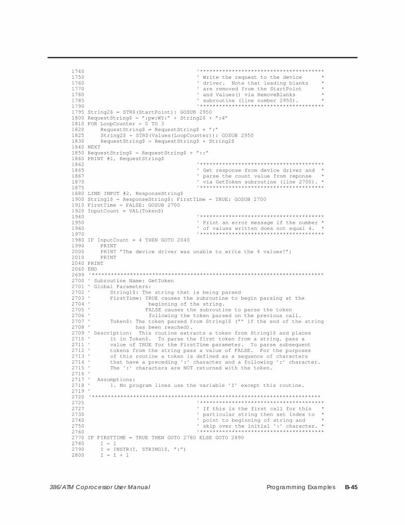
Programming Examples B-45386/ATM Coprocessor User Manual
1740 ’***************************************1750 ’ Write the request to the device *1760 ’ driver. Note that leading blanks *1770 ’ are removed from the StartPoint *1780 ’ and Values() via RemoveBlanks *1785 ’ subroutine (line number 2950). *1790 ’***************************************1795 String2$ = STR$(StartPoint): GOSUB 29501800 RequestString$ = ”:pw:WY:” + String2$ + ”:4”1810 FOR LoopCounter = 0 TO 31820 RequestString$ = RequestString$ + ”:”1825 String2$ = STR$(Values(LoopCounter)): GOSUB 29501830 RequestString$ = RequestString$ + String2$1840 NEXT1850 RequestString$ = RequestString$ + ”::”1860 PRINT #1, RequestString$1862 ’***************************************1865 ’ Get response from device driver and *1867 ’ parse the count value from reponse *1870 ’ via GetToken subroutine (line 2700). *1875 ’***************************************1880 LINE INPUT #2, ResponseString$1900 String1$ = ResponseString$: FirstTime = TRUE: GOSUB 27001910 FirstTime = FALSE: GOSUB 27001920 InputCount = VAL(Token$)1940 ’***************************************1950 ’ Print an error message if the number *1960 ’ of values written does not equal 4. *1970 ’***************************************1980 IF InputCount = 4 THEN GOTO 20401990 PRINT2000 PRINT ”The device driver was unable to write the 4 values!”;2010 PRINT2040 PRINT2060 END2699 ’*************************************************************************2700 ’ Subroutine Name: GetToken2701 ’ Global Parameters:2702 ’ String1$: The string that is being parsed2703 ’ FirstTime: TRUE causes the subroutine to begin parsing at the2704 ’ beginning of the string.2705 ’ FALSE causes the subroutine to parse the token2706 ’ following the token parsed on the previous call.2707 ’ Token$: The token parsed from String1$ (”” if the end of the string2708 ’ has been reached).2709 ’ Description: This routine extracts a token from String1$ and places2710 ’ it in Token$. To parse the first token from a string, pass a2711 ’ value of TRUE for the FirstTime parameter. To parse subsequent2712 ’ tokens from the string pass a value of FALSE. For the purposes2713 ’ of this routine a token is defined as a sequence of characters2714 ’ that have a preceding ’:’ character and a following ’:’ character.2715 ’ The ’:’ characters are NOT returned with the token.2716 ’2717 ’ Assumptions:2718 ’ 1. No program lines use the variable ’I’ except this routine.2719 ’2720 ’************************************************************************2725 ’***************************************2727 ’ If this is the first call for this *2730 ’ particular string then set index to *2740 ’ point to beginning of string and *2750 ’ skip over the initial ’:’ character. *2760 ’***************************************2770 IF FIRSTTIME = TRUE THEN GOTO 2780 ELSE GOTO 28902780 I = 12790 I = INSTR(I, STRING1$, ”:”)2800 I = I + 1
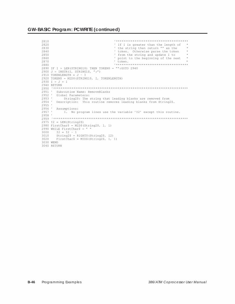
Programming ExamplesB-46 386/ATM Coprocessor User Manual
GW-BASIC Program: PCWRITE (continued)
2810 ’***************************************2820 ’ If I is greater than the length of *2830 ’ the string then return ”” as the *2840 ’ token. Otherwise parse the token *2850 ’ from the string and update I to *2860 ’ point to the beginning of the next *2870 ’ token. *2880 ’***************************************2890 IF I > LEN(STRING1$) THEN TOKEN$ = ””:GOTO 29402900 J = INSTR(I, STRING1$, ”:”)2910 TOKENLENGTH = J – I2920 TOKEN$ = MID$(STRING1$, I, TOKENLENGTH)2930 I = J + 12940 RETURN2950 ’*************************************************************************2951 ’ Subroutine Name: RemoveBlanks2952 ’ Global Parameters:2953 ’ String2$: The string that leading blanks are removed from2954 ’ Description: This routine removes leading blanks from String2$.2955 ’2956 ’ Assumptions:2957 ’ 1. No program lines use the variable ’I2’ except this routine.2958 ’2959 ’*************************************************************************2975 I2 = LEN(String2$)2980 FirstChar$ = MID$(String2$, 1, 1)2990 WHILE FirstChar$ = ” ”3000 I2 = I2 – 13010 String2$ = RIGHT$(String2$, I2)3020 FirstChar$ = MID$(String2$, 1, 1)3030 WEND3040 RETURN

Pinouts C-1386/ATM Coprocessor User Manual
Appendix C
Pinouts
13
114
25
Parallel
1. Strobe 14. Autofeed2. Data0 15. Error3. Data1 16. Initialize4. Data2 17. Select input5. Data3 18. Ground6. Data4 19. Ground7. Data5 20. Ground8. Data6 21. Ground9. Data7 22. Ground
10. Ack 23. Ground11. Busy 24. Ground12. Paper out 25. Ground13. Select
I001695
Figure C-1 Parallel Port Pinout
1. Ground2. Secondary red3. Primary red4. Primary green5. Primary blue6. Secondary green/intensity7. Secondary blue8. Horizontal sync9. Vertical sync
5
16
9
Video
I001696
This pinout is for modules with serial numbers prior to86AT9107xxxxxx, unless the module has been upgraded toanalog (indicated by a U at the end of the serial number).
Figure C-2 TTL VGA Port Pinout
5
16
9
Video (analog)1. Red video2. Green video3. Blue video4. H sync5. V sync6. Red return7. Green return8. Blue return9. Chassis Ground
Figure C-3 Analog VGA Port Pinout
1
Keyboard
1. Clock2. Data3. Not Used4. Ground5. +5VDC
I001697
35
2
4
Figure C-4 Keyboard Connector Pinout
5
16
9
Serial (Com 1 and Com 2)
1. DCD2. RX3. TX4. DTR5. Ground6. DSR7. RTS8. CTS9. RI
I001698
Figure C-5 Serial Port 1 and 2 Pinout
9-pin male 15-pin female
1
2
3
4
5
6
7
8
9
1.
2.
3.
13.
14.
6.
7.
8.
4.
5.
10.
11.
Red
Green
Blue
H sync
V sync
Red return
Green return
Blue return
Ground
Ground
Ground
Ground
(May or may not beneeded, depending
on the monitor used.)
Figure C-6 9-pin Analog VGA to 15-Pin VGAAdapter Cable Pinout
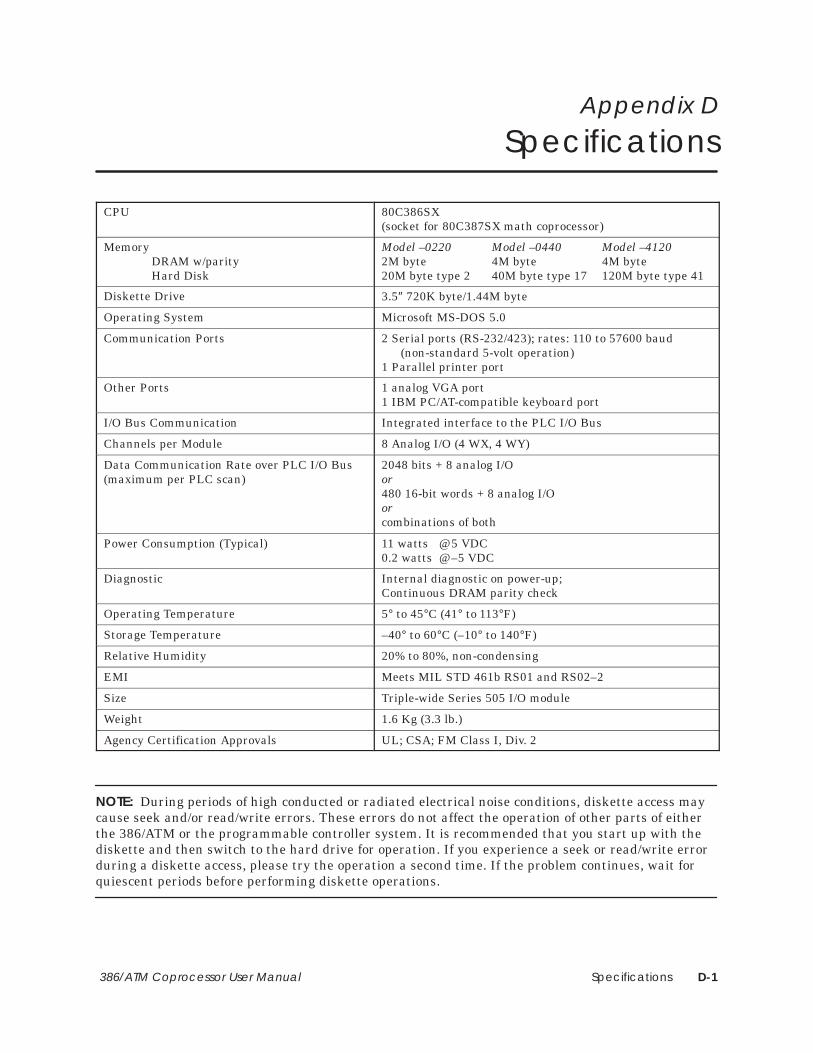
Specifications D-1386/ATM Coprocessor User Manual
Appendix D
Specifications
CPU 80C386SX (socket for 80C387SX math coprocessor)
MemoryDRAM w/parityHard Disk
Model –0220 Model –0440 Model –41202M byte 4M byte 4M byte20M byte type 2 40M byte type 17 120M byte type 41
Diskette Drive 3.5″ 720K byte/1.44M byte
Operating System Microsoft MS-DOS 5.0
Communication Ports 2 Serial ports (RS-232/423); rates: 110 to 57600 baud(non-standard 5-volt operation)
1 Parallel printer port
Other Ports 1 analog VGA port1 IBM PC/AT-compatible keyboard port
I/O Bus Communication Integrated interface to the PLC I/O Bus
Channels per Module 8 Analog I/O (4 WX, 4 WY)
Data Communication Rate over PLC I/O Bus(maximum per PLC scan)
2048 bits + 8 analog I/O or480 16-bit words + 8 analog I/Oorcombinations of both
Power Consumption (Typical) 11 watts @ 5 VDC0.2 watts @ –5 VDC
Diagnostic Internal diagnostic on power-up;Continuous DRAM parity check
Operating Temperature 5° to 45°C (41° to 113°F)
Storage Temperature –40° to 60°C (–10° to 140°F)
Relative Humidity 20% to 80%, non-condensing
EMI Meets MIL STD 461b RS01 and RS02–2
Size Triple-wide Series 505 I/O module
Weight 1.6 Kg (3.3 lb.)
Agency Certification Approvals UL; CSA; FM Class I, Div. 2
NOTE: During periods of high conducted or radiated electrical noise conditions, diskette access maycause seek and/or read/write errors. These errors do not affect the operation of other parts of eitherthe 386/ATM or the programmable controller system. It is recommended that you start up with thediskette and then switch to the hard drive for operation. If you experience a seek or read/write errorduring a diskette access, please try the operation a second time. If the problem continues, wait forquiescent periods before performing diskette operations.

Customer Registration
We would like to know what you think about our user manuals so that we can serve you better.How would you rate the quality of our manuals?
Excellent Good Fair Poor
AccuracyOrganizationClarityCompletenessOverall designSizeIndex
Would you be interested in giving us more detailed comments about our manuals?
Yes! Please send me a questionnaire.
No. Thanks anyway.
Your Name:
Title:
Telephone Number: ( )
Company Name:
Company Address:
Manual Name: SIMATIC TI505 386/ATM Coprocessor User Manual Edition: Third
Manual Assembly Number: 2586546-0056 Date: 02/93
Order Number: PPX:505-ATM-MANL-3
BUSINESS REPLY MAILFIRST CLASS PERMIT NO.3 JOHNSON CITY, TN
FOLD
FOLD
POSTAGE WILL BE PAID BY ADDRESSEE
NO POSTAGENECESSARYIF MAILED
IN THEUNITED STATES
SIEMENS INDUSTRIAL AUTOMATION, INC. 3000 BILL GARLAND RD.P.O. BOX 1255JOHNSON CITY TN 37605–1255
ATTN: Technical Communications M/S 3519