simeas p power meter - novec.ru · simeas p screens 4 siemens sr 10.3.1 ⋅2001 up to 20 screens...
TRANSCRIPT
POWER QUALITY
Catalog SR 10.3.12001
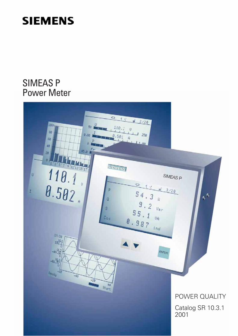
SIMEAS PPower Meter

SIMEAS P
Description 3
Screens 4 to 6
Configuration,
Communication 6
Limit values 7
Parameters 7
Software 8
Typical terminal assignments 9
Technical data 10
Specifications and standards 11
Selection and ordering data 12
Terminals 12
Dimensions 12
Appendix
Content
Siemens AG 2001
Direct-reading panel-mounted measuring de-vice for measurement ofpower supply parame-ters.
Large, easy to readgraphic display with bluebacklighting.
Standard PROFIBUSDPinterface for cyclic trans-mission of measured val-ues to central processorsup to 12 Mbit/sec.
Suitable for balancedand unbalanced three-and four-wire three-phasesystems as well as sin-gle-phase systems.
Easy configurationand calibration from thefront panel or viaPC-based configurationsoftware.
User-specific adapta-tion of the measured-value screens.
2 relay outputs canbe configured for energypulses, limit violations orstatus signals.
Measured parame-ters:– R.m.s. phase-voltages– R.m.s. phase-currents– System frequency– Active, reactive and ap-
parent power as wellas power factor perphase and for the totalsystem.
– Phase current and volt-age imbalance.
– Harmonic voltages andcurrents up to the 21st
harmonic.– Total current and volt-
age harmonic distortionTHD.
– Active, reactive and ap-parent power demandper phase and for thetotal system.
Constant high accu-racy for years, CE desig-nation, EMC strength.
High system securityand reliability.
Compliance with allrelevant national and in-ternational standards.
2 Siemens SR 10.3.1 ⋅ 2001

Application
SIMEAS P is a panel-mounteddevice for direct reading ofpower system parameters.With a very simple configura-tion, the display of measuredvalues is adaptable to the spe-cific requirements of the user.Power system linking is possi-ble with the integral RS485port equipped with the stand-ard PROFIBUS DP protocol(optional: MODBUS, DNP V3.0)which provides for indication,evaluation and processing ofseveral SIMEAS P measuredvalues at a central master sta-tion.
Technology
Powerful onboard microproc-essors ensure ultra-fast regis-tration and updating of meas-ured values.SIMEAS P can be connectedto any power system configu-ration directly (up to 690 V-systems) or via transformer -from single-phase to four-wirebalanced or unbalancedthree-phase systems. Thepower supply unit allows ratedsupply voltages from 24 to250 V DC and 100 to 230 V ACmaking the SIMEAS P reallyuniversal.
Design
The front panel with inte-grated keys and high-resolu-tion blue-backlit graphic dis-play gives the SIMEAS P asmart appearance that empha-sizes its high-tech features.
Operation
The SIMEAS P simplicity ofdesign translates into easyand comprehensive operation.Terminology and descriptionsin national language providesfor rapid menu-assisted con-figuration of the unit.
Display
All parameters can be dis-played on the SIMEAS Pscreens as required by theuser. Up to 20 screens can beselected with the front keys.Number, type, content and se-quence of the screens areconfigurable.SIMEAS P is delivered withprogrammed default settings.A status line displayed in themeasured-value screens indi-cates status, interfacing anddiagnostic messages ofSIMEAS P.The status line is automaticallyrefreshed every 1 s.
Inputs/ Outputs
Figure 2 shows the I/O pinconfiguration of SIMEAS P.Depending on the type ofpower system, the non-re-quired inputs remain unas-signed.
Communication
As communication betweenfield devices is becoming stan-dard, development of theSIMEAS P communication in-terface focussed on the uni-versality and flexibility of thetransmission protocol. It isconnected via an RS485 portwith standard 9-pin SUB-Dconnector. SIMEAS P unitsare delivered with a standardPROFIBUS DP protocol withtransmission rates of up to12 Mbit/s. With auxiliary soft-ware SIMEAS P can also useother communication proto-cols. The integration ofMODBUS and DNP V3 is inpreparation. Future protocolsor modifications and exten-sions of present standard pro-tocols can be integrated later.
Description
Measuring functions
Measured input voltages andinput currents are sampled forcalculation of the correspond-ing r.m.s. values. All parame-ters derived from measuredvalues are calculated by aprocessor.They can be displayed on thescreens and/or transmitted viathe serial interface.With the SIMEAS P it is alsopossible to parameterize sev-eral limit value groups withlimit values of the parameters.These may be combined withlogical elements such asAND,OR; violations arecounted and indicated on thescreen or made available atthe binary outputs. Triggeringof the oscilloscope is possibleas well.
Security
Electrical isolation between in-puts and outputs, assured byhigh-voltage testing, guaran-tees maximum system secu-rity. Configuration and calibra-tion settings are tamperproofby password protection.
Service
SIMEAS P units are availableex stock. They require nomaintenance and are easy toservice due to their modulardesign.The units can easily be cali-brated via the front keys orwith PC-based configurationsoftware.
Siemens SR 10.3.1 ⋅ 2001 3
Fig. 2 Inputs / outputs
Fig. 1 SIMEAS P
SR31
090-
afp.
eps

SIMEAS P
Screens
4 Siemens SR 10.3.1 ⋅ 2001
Up to 20 screens can be selected on thedisplay of SIMEAS P with the front keys.If requested, this routine is executed auto-matically.• Number, type and sequence of the
screens are freely configurable.• 9 different types of screens can be se-
lected:– 4 measured-value screens– 1 list screen for minimum, average
and maximum values– 2 screens for harmonics– 1 screen serving as oscilloscope– 1 screen serving as phasor diagram
Measured-value screens
• Number and content of the measured-value screens and the parameters aredetermined individually by the user.
• In addition, designations for the param-eters are available for selection in thedefault setting:UL1, UL2, UL3, cos ϕ, etc. orVa, Vb, Vc, PF etc.
• To obtain a higher resolution, the lowerand upper measuring value can be setin the bar chart display.
• Measured-value screens can be se-lected as often as required.
• Status and diagnostic messages of thedevice are indicated in the status linedisplayed on the measured-valuescreens.
• The screens are automatically updatedevery 1 s.
Fig. 3Representation of up to 20 screens,selectable with thefront keys s t
Fig. 42 measured values, digital
Fig. 52 measured values, digital analog
Fig. 64 measured values, digital

Siemens SR 10.3.1 ⋅ 2001 5
Oscilloscope
• 3 parameters for voltage or current canbe selected from the table (see page 7)of parameters and recorded withpre-fault.
• Recording is started manually or trig-gered automatically, as soon as anout-of-limit condition occurs.
• The cursor is shifted via the front keys.Measured values are read off with timeindication from the cursor position onthe X- and Y-axis.
• Also for recording of r.m.s. values up to3 parameters can be selected from thetable of parameters.
• The parameter level is optimized auto-matically in the screens.
• The recording section displayed is indi-cated at the bottom of the oscilloscopescreen.
Vector diagram
State and pulse value of currents and volt-ages as well as their phase angles can beread off from the phasor diagram screen.
Fig. 74 measured values, digital analog
Fig. 8Oscilloscope for sinusoidal values
Fig. 9Oscilloscope for r.m.s. values
Fig. 10Vector diagram

Harmonics
2 screens are available for themeasured harmonics:• Harmonic voltages
Harmonic currents• All three phases with all
odd-order harmonics up tothe 21st harmonic are dis-played on the screens.
• Each harmonic can be indi-cated individually in a digitaldisplay in the top right-handcorner of the screen andcan be selected via the frontkeys.
List screens
• Minimum, average andmaximum values of the pa-rameters are indicated onthe list screens from the be-ginning of the recordingprocess.
• Start and reset of the re-cording process is done viathe front keys.
• The parameters are freelyconfigurable with regards totheir number and sequence.
Configuration
• Configuration of SIMEAS Pis very easy.
• Rapid configuration (evenwithout consulting the man-ual) possible due to detailedindex and operation via cur-sor and enter-key.
• Configuration and calibrationsettings are tamperproofdue to password protection.
Communication
SIMEAS P is equipped with acommunication port in compli-ance with the EIA standardRS485 with a standard 9-pinSUB-D connector for connec-tion to RS485 field bus sys-tems. SIMEAS P is deliveredwith an integrated standard• PROFIBUS DP V1 protocol
in compliance withEN 50170 Volume2.(PROcessFIeldBUS)
With help of the auxiliary soft-ware SIMSOFT P also otherprotocols such as• MODBUS or• DNP V3(in preparation) can be loaded.Therefore, SIMEAS P supportsall commonly used communi-cation protocols.
PROFIBUS DP
PROFIBUS DP and SIMEAS Pare connected in a master-slave operation mode. Thecommunication parametersare loaded to the master sta-tion using the GSD file.SIMEAS P supports datatransmission rates rangingfrom 9.6 kBit/s to 12 Mbit/s.Optionally the user may select4 different types of transmis-sion for data transfer to themaster station.• Type 1: transmission of
3 parameters• Type 2: transmission of
6 parameters• Type 3: transmission of
12 parameters• Type 4: transmission of
32 parametersThis option provides for sim-ple, efficient and fast datacommunication betweenSIMEAS P and master station.The 3, 6, 12 or 32 measuredvalues for transmission types1 to 4 may be selected fromthe table of the parameters(see page 7).
SIMEAS P
Screens, configuration, communication
6 Siemens SR 10.3.1 ⋅ 2001
Fig. 14SIMEAS P with PROFIBUS DP
Fig. 11Harmonics
Fig. 12List screens
Fig. 13Configuration

Limit values, parameters
Limit values
Several limit value groups withup to 6 selectable parameterscan be set in the SIMEAS P.They may be combined withlogical elements such as AND,OR, limit violations arecounted, they are available atbinary outputs or serve fortriggering the oscilloscope.
Binary outputs
The basic SIMEAS P isequipped with 2 binary outputswhich are free for configurationwith:• Status signals• Energy values from the ta-
ble of parameters• Limit violations
Parameter Measured path1)
Unit Menu Tolerances2)
Voltage L1-N, L2-N, L3-N, (N-E) V, kV t n l ± 0.2 %
Voltage L1-L2, L2-L3, L3-L1, Σ3) V, kV t n l ± 0.2 %
Current L1, L2, L3, N, Σ3) A, kA t n l ± 0.2 %
Active power P+ import, - export
L1, L2, L3, Σ W, kW, MW t n l ± 0.5 %
Reactive power Q L1, L2, L3, Σ Var, kvar, Mvar t n l ± 0.5 %
Apparent power S L1, L2, L3, Σ VA, kVA, MVA t n l ± 0.5 %
Power factor cosϕ L1, L2, L3, Σ t n l ± 0.5 %
Active power factor cosϕ L1, L2, L3, Σ t n l ± 0.5 %
Phase angel L1, L2, L3, Σ ° t n l ± 2 °
System frequency L1, L2 Hz t n l ± 10 mHz
Active energy E import L1, L2, L3, Σ kWh, MWh t n ± 0.5 %
Active energy E export L1, L2, L3, Σ kWh, MWh t n ± 0.5 %
Reactive energy Q L1, L2, L3, Σ kVarh, Mvarh t n ± 0.5 %
Apparent energy ES L1, L2, L3, Σ VA, kVA, MVA t n ± 0.5 %
Energy balance L1, L2, L3, Σ W, kW, MW t n ± 0.5 %
Energy absolute L1, L2, L3, Σ W, kW, MW t n ± 0.5 %
Unbalance voltage four-wire system % t n l ± 0.5 %
Unbalance current four-wire system % t n l ± 0.5 %
THD voltage L1, L2, L3 % t n l ± 0.5 %
THD current L1, L2, L3 % t n l ± 0.5 %
Harmonics V 5th, 7th, 11th, 13th, 17th, 19th L1, L2, L3 % t n l ± 0.5 %
Harmonics I 5th, 7th, 11th, 13th, 17th, 19th L1, L2, L3 A t n l ± 0.5 %
Limit violations counter Counter 1, 2, 3, 4 t n
Siemens SR 10.3.1 ⋅ 2001 7
t Parameters displayable on themeasured-value screens
n Parameters selectable via com-munication
l Parameters selectable for listscreens and oscilloscope
1) Phases are displayed in depend-ence of the type of connection
2) With reference to the 1.2 x nom-inal value
3) Average value of all phases
Parameters
Fig. 15Limit valuesOther configurable parameters
are, for example, pulse dura-tion, hysteresis and pulsevalue of the energy parameter.

With the SIMEAS P softwarethe user benefits from a sim-ple and user-friendly toolwhich will exploit the func-tions of the SIMEAS P evenmore efficiently. The packageconsists of three programunits which may be installedseparately as requested:• Configuration• Visualization• EvaluationAs an accessory, a configura-tion cable with RS232/485converter is available. TheSIMEAS P can be connectedto any standard notebook orPC by means of a 9-pin SUB-Dconnector. Installation underWindows 95 / NT.
Configuration
The configuration software asshown in Fig. 17 permitsultrafast configuration ofSIMEAS P units. The user canset and store parameters evenwithout having the actual unitby his side. The parameters willbe transferred to SIMEAS Pwhen the“Send to unit“ com-mand is activated.In this manner a number ofSIMEAS P units can be config-ured with minimum effort. Thestored set of parameters issimply re-loaded when a unithas to be replaced. Further-more, communication proto-cols and firmware updates canbe loaded with help of theSIMEAS P software.
Visualization
The SIMEAS P software offersthe user the possibility of on-line retrieval, evaluation andtime-stamped printing of meas-ured values remotely from aPC or notebook.Independent of the SIMEAS Pdisplay all parameters deter-mined in SIMEAS P can bepresented on a graphic dis-play.
Evaluation
The sinusoidal or r.m.s.-valuesrecorded by SIMEAS P can bedisplayed (Fig. 19) and pro-cessed very professionally andprinted out in graphical or tab-ular form. All relevant meas-ured values can also be se-lected and recorded from thePC or notebook with the samepossibilities of representationand evaluation.The records may be subjectedto further processing by a vari-ety of user-friendly tools.Setting or shifting of up to 8cursors is possible with onlinerepresentation of the meas-ured values at the specific cur-sor position in tabular form.Other features:Zooming, labelling, storing andprinting of selected parame-ters etc.
SIMEAS P
Software
8 Siemens SR 10.3.1 ⋅ 2001
Fig. 17Configuration
Fig. 18Visualization
Fig. 19Evaluation
Fig. 16Configuration
SR31
107-
afpe
n.tif
SR31
108-
afpe
n.tif
SR31
109-
afpe
n.tif

Typical terminal assignments
Siemens SR 10.3.1 ⋅ 2001 9
The above-mentioned terminal assignments are just someconfiguration examples. Within the range of the admissiblemaximum current and voltage values a current or voltagetransformer is not compulsory.
On the other hand, Y- or V-connected voltage transformerscan be used.All input or output terminals not required for measurementremain unassigned.
Fig. 244-wire – 3-phase current, any loading(low-voltage system)
Fig. 20Single-phase AC current
Fig. 214-wire – 3-phase current, balanced loading
Fig. 223-wire – 3-phase current, balanced loading
Fig. 233-wire – 3-phase current, any loading
Fig. 254-wire – 3-phase current, any loading(high-voltage system)

SIMEAS P
Technical data
10 Siemens SR 10.3.1 ⋅ 2001
Display high-resolution graphic display
ResolutionDimensionsBackground illumination
120 x 240 pixels103 x 60 mmblue
Communication interface
InterfaceTermination systemTransmission rate
Transmission protocols
9-pin SUB-D connector12 MBauds max. with PROFIBUSPROFIBUS DP V1.0
Ambient temperature acc. to IEC 60 688
Operating temperature rangeStorage/transportationtemperature range
0 °C to +55 °C, 32 °F to +131 °F–25 °C to +70 °C, –13 °F to +158 °F
Utilization category IR2 (environment)
Dielectric strength
Acc. to IEC 60 688 5 kV 1.2 / 50 µs
Dimensions and housing construction
Dimensions
Housing construction
Connector elementsAuxiliary powerVoltage inputsCurrent inputsBinary outputsRS485 bus interface
144 x 144 x 82.5 mm (5.6 x 5.6 x 3.2 inches)(width x height x depth)Panel-mounting housing according toDIN 43700Degree of protection IP 42 (Front)Degree of protection IP 20 (Terminals)Terminal for cable diameter 2.5 mm2
Terminal for cable diameter 2.5 mm2
Terminal for cable diameter 4.0 mm2
Terminal for cable diameter 2.5 mm2
9-pin SUB-D connector
Weight
Weight approx. 0.9 kg
Input for connection to AC systems only
Max. system nominal voltageControl rangeRated frequency fENInput frequency range fEWaveform
Y 400 /∆ 690 V1.2 VEN / IEN50 Hz; 60 Hz± 5 Hz from 10 % VEN or highersinusoidal or distorted up to the 21stharmonic
AC current input IE
Rated input current IENContinuous overloadSurge withstand capabilityPower consumption
1 A; 5 A10 A100 A for 1s83 µVA at 1A ; 2.1 mVA at 5 A
AC voltage input VE
Rated voltage EU version VEN
Continuous overload capacitySurge withstand capabilityInput resistancePower consumption
100 / 110 V; 190 V; 400 V; 690 V(phase-phase)1.5 x VEN2.0 x VEN2.663 MΩ120 mW (VEN = 400 V)
Surge voltage category acc. to DIN EN 61010 Part 1
VEN to 400 V (phase-phase)VEN to 690 V (phase-phase)
IIIII
Auxiliary power multi-range power supply unit AC/DC.
Rated rangeTotal rangePower consumption
24 to 250 V DC or 100 to 230 V AC± 20 % of rated rangemax. 6 W
Binary outputs via isolated solid-state relay
Permissible voltagePermissible current
Output resistancePermissible switchingfrequency
230 V AC ; 400 V DC150 mA continuous500 mA for 100 ms12.5 Ω10 Hz

Standard Reference to Test
IEC 60 688 IEC 60 521 Surge withstand capability test 5 kV; pulse shape 1.2 / 50 µs, creepage distances and clearances
IEC 60 688 IEC 60 255-22-1 1 MHz high-frequency disturbance test 2.5 kV / 1.0 kV
IEC 60 688 Temperature test with impressed overcurrents and overvoltages
EMC regulation EN 50011 Radio interference voltage and emitted interference according to limit class A
EMC regulation IEC 61 000-4-2 Electrostatic discharge 4 kV contact and 8 kV air discharge
EMC regulation IEC 61 000-4-3 Electromagnetic RF fields 10 V/mFrequency range 80 –1000 MHz amplitude-modulatedFrequency 900 MHz pulse-modulated
EMC regulation IEC 61 000-4-4 Electrical fast transient pulse shape 2 kV pulse shape 5 / 50 ns
EMC regulation IEC 61 000-4-5 Lightning impulse test – surge pulse shape 1.2 / 50 µs
EMC regulation IEC 61 000-4-6 Amplitude-modulated supply with RF power 10 V / 0.15 – 80 MHz
EMC regulation IEC 61 000-4-8 Power frequency magnetic fields immunity test 30 A/m
EMC regulation IEC 61 000-3-2 Harmonic power system currents
EMC regulation IEC 61 000-3-3 Supply voltage fluctuations
EN 61010-1 IEC 60 664 Insulation test
EN 61010-1 Mechanical strength test
EN 61010-1 IEC 60 817 Impact test
EN 61010-1 IEC 60 068-2-6 Vibration test
Specifications and standards
Specifications and stand-ards
The SIMEAS P unit complieswith the product standardsIEC 688 / IEC 60688. This gen-eral standard refers to all sin-gle specifications where testprocedures are described indetail. Furthermore, all stand-ards to be complied with inconformity with EC regula-tions as well as the Europeanstandard EN 61010 (VDE 0411)Part 1, describing the safetyregulations for measuring,control and laboratory equip-ment are applicable.
Siemens SR 10.3.1 ⋅ 2001 11

Terminal assignment
Dimensions in mm (in inches)
SIMEAS P
Selection and ordering data
12 Siemens SR 10.3.1 ⋅ 2001
Designation Order No.
SIMEAS Pwith PROFIBUS DP V1 interface
7KG7000–8AA
SIMEAS P configuration packageconsisting of:
Softwarefor configuration, calibrationdata readout and analysisof SIMEAS P unitsby means of a personal computer
Cable connector for connecting SIMEAS P tothe PClength 5 mincl. RS232/RS485 converterConnector:PC side:9-pin SUB-D connector, femaleSIMEAS P side:9-pin SUB-D connector, male
7KG7050–8AA
Mounting kitfor snap-on mounting on a 35 mmDIN rail according to DIN EN 50022
7KG7052–8AA
Terminals, dimensions
Fig. 26SIMEAS P terminals – rear view
Fig. 27Side view

Catalog Index of the Power Transmission and Distribution, Power Automation Division
Appendix
Siemens SR 10.3.1 ⋅ 2001 13
Title Designation Order No.:
Power QualityFault and Digital Recorder SIMEAS R SR 10.1.1 E50001-K4011-A101-A1-7600Central Fault Data Unit DAKON SR 10.1.2 see IntranetOSCOP P The Program for Power Quality Recorders SR 10.1.3 E50001-K4013-A101-A1-7600
Power System Quality Analysis OSCILLOSTORE SR 10.2 E50001-K4020-A101-A1-7600SIMEAS Q Quality Recorder SR 10.2.5 E50001-K4025-A101-A1-7600SIMEAS P Power Meter SR 10.3.1 E50001-K4031-A101-A1-7600SIMEAS T Transducers for Power Variables SR 10.4 E50001-K4040-A101-A1-7600Low Voltage Capacitors and Power Factor Correction Units SIPCON T SR 10.6 E50001-K4060-A101-A1-7600
Energy Automation
Substation SICAM RTU System SICAM 2.1.1 E50001-K5602-A111-A1-7600SICAM miniRTU 6MD202 Remote Terminal Unit SICAM 2.2.1 E50001-K5602-A211-A2-7600SICAM microRTU 6MD203 Remote Terminal Unit SICAM 2.3.1 E50001-K5602-A311-A3-7600SICAM SAS Substation Automation System SICAM 3.1.1 E50001-K5603-A111-A1-7600PS20A-6EP8090 Power Supply Module SICAM 5.1.1 E50001-K5605-A111-A1-7600DI32-6MD1021 Digital Input Functional Module SICAM 5.2.1 E50001-K5605-A211-A1-7600AI32-6MD1031 Analog Input Functional Module SICAM 5.2.2 E50001-K5605-A221-A1-7600AI16-6MD1032 Analog Input Functional Module SICAM 5.2.3 E50001-K5605-A231-A1-7600Visualization System for SICAM SAS: SICAM WinCC SICAM 6.1.1 E50001-K5606-A111-A2-7600SICAM plusTOOLS Configuration System SICAM 6.2.1 E50001-K5606-A211-A1-7600
Numerical Protective Relaying
Numerical Protection Devices LSA 2.0.1 E50001-K5702-A011-A1-7600Operation and Evaluation Software for Numerical Protection Devices LSA 2.0.2 E50001-K5702-A121-A1-7600Relay Selection Guide LSA 2.0.3 E50001-K5702-A031-A2-7600SIPROTEC 7SJ601 Overcurrent Protection LSA 2.1.16 E50001-K5712-A261-A1-76007SJ41 Definite-Time Overcurrent Protection Relay LSA 2.1.10 E50001-K5712-A201-A2-76007SJ511 Numerical Overcurrent-Time Protection (Version V3) LSA 2.1.3 E50001-K5712-A131-A2-76007SJ512 Numerical Overcurrent-Time Protection (Version V3) LSA 2.1.4 E50001-K5712-A141-A3-76007SJ512 Numerical Feeder Protection (Version V3.6) LSA 2.1.30 E50001-K5712-A411-A1-4A00SIPROTEC 7SJ531 Numerical Line and Motor Protection withControl Function LSA 2.1.9 E50001-K5712-A191-A4-76007SJ551 Multi-Function Protection Relay LSA 2.4.2 E50001-K5742-A121-A3-7600SIPROTEC 4 7SJ61/62/63 6MD63 Multifunction Protection Relayand Bay Controller SIP 3.1 E50001-K4403-A111-A1-4A00SIPROTEC 7SJ600 Numerical Overcurrent, Motor and OverloadProtection Relay SIP 3.2 E50001-K4403-A121-A1-7600SIPROTEC 7SJ602 Numerical Overcurrent, Motor and OverloadProtection Relay SIP 3.3 E50001-K4403-A131-A1-7600SIPROTEC 7SA510 Distance Protection Relay (Version V3) LSA 2.1.17 E50001-K5712-A271-A1-7600SIPROTEC 7SA511 Distance Protection Relay (Version V3) LSA 2.1.11 E50001-K5712-A211-A2-76007SA513 Line Protection Relay (Version V3) LSA 2.1.12 E50001-K5712-A221-A1-76007SA518/519 Overhead Control-Line Protection Relay (Version V3) LSA 2.1.14 E50001-K5712-A241-A2-7600SIPROTEC 4 7SA6 Distance Protection Relay for all Voltage Levels SIP 4.3 E50001-K4404-A131-A1-76003VU13 Miniature Circuit-Breaker LSA 2.1.8 E50001-K5712-A181-A2-76007SD502 Line Differential Protection with Two Pilot Wires LSA 2.2.1 E50001-K5722-A111-A2-76007SD503 Line Differential Protection with Three Pilot Wires LSA 2.2.2 E50001-K5722-A121-A2-76007SD511/512 Current Comparison Protection Relay (Version V3)for Overhead Lines and Cables LSA 2.2.3 E50001-K5722-A131-A2-7600SIPRPOTEC 7SD60 Numerical Current Differential Protection Relayfor Two Pilot-Wire Link SIP 5.2 E50001-K4405-A121-A2-7600SIPROTEC 4 7SD610 Universal Differential Protection Relayfor Two Line Ends SIP 5.4 E50001-K4405-A141-A1-76007UT512/513 Differential Protection Relay (Version V3)for Transformers, Generators and Motors LSA 2.2.4 E50001-K5722-A141-A2-7600SIPROTEC 7SS50 Version V1.2 Busbar/Circuit-BreakerFailure Protection Relay (Summation Current Transformer Version) SIPROTEC 5.1 E50001-K4405-A111-A1-7600Auxiliary Current Transformers 4AM50, 4AM51, 4AM52and Isolating Transformers 7XR95 LSA 2.2.6 E50001-K5722-A161-A1-7600SIPROTEC 7SS52 Distributed Numerical Busbar and Circuit-BreakerFailure Protection Relay LSA 2.2.7 E50001-K5722-A171-A1-7600Introduction to Earth-Fault Detection LSA 2.3.1 E50001-K5732-A111-A2-76007SN71 Transient Earth-Fault Relay LSA 2.3.2 E50001-K5732-A121-A1-76007XR96 Toroidal Current Transformer LSA 2.3.3 E50001-K5732-A131-A1-76007VC1637 Earth-Leakage Monitor LSA 2.3.4 E50001-K5732-A141-A1-76007SK52 Motor Protection LSA 2.4.1 E50001-K5742-A111-A1-7600Introduction to Generator Protection LSA 2.5.1 E50001-K5752-A111-A1-7600

Title Designation Order No.:
Numerical Protective Relaying
7UM511 Generator Protection Relay (Version V3) LSA 2.5.2 E50001-K5752-A121-A2-76007UM512 Generator Protection Relay (Version V3) LSA 2.5.3 E50001-K5752-A131-A2-76007UM515 Generator Protection Relay (Version V3) LSA 2.5.4 E50001-K5752-A141-A2-76007UM516 Generator Protection Relay (Version V3) LSA 2.5.5 E50001-K5752-A151-A1-7600SIPROTEC 4 7UM611/612 Multifunction Generator Protection Relay SIP 6.1 E50001-K4406-A111-A1-7600SIPROTEC 4 7UM62 Multifunction Generator, Motor and Transformer SIP 6.2 E50001-K4406-A121-A1-7600Protection Relay7UW50 Tripping Matrix LSA 2.5.6 E50001-K5752-A161-A1-76007VE51 Synchronizing Unit LSA 2.5.7 E50001-K5752-A171-A1-76007VP151 Three-Phase Portable Test Set (Omicron CMC56) LSA 2.6.1 E50001-K5762-A111-A2-76007XV72 Test Switch LSA 2.6.2 E50001-K5762-A121-A1-76007SV50 Numerical Circuit-Breaker Failure Protection Relay LSA 2.7.1 E50001-K5772-A111-A1-76007SV512 Numerical Circuit-Breaker Failure Protection Relay LSA 2.7.2 E50001-K5772-A121-A1-76007VK512 Numerical Auto-Reclose/Check-Synchronism Relay LSA 2.7.3 E50001-K5772-A131-A1-76007SM70 Analog Output Unit LSA 2.7.5 E50001-K5772-A151-A1-76007SM71 Analog Output Unit LSA 2.7.6 E50001-K5772-A161-A1-76007SV7220 Power Supply Unit LSA 2.7.9 E50001-K5772-A191-A1-7600SIPROTEC 7RW600 Numerical Voltage, Frequency andOverexitation Relay SIP 2.1 E50001-K4402-A111-A1-7600Communication for Protection DevicesCentralized and Remote Control of Siemens Protection Relays (Overview) SIPROTEC 8.1 E50001-K4408-A111-A1-7600DIGSI 4 - Software for Configuration and Operation of SIPROTEC 4 units SIP 8.2 E50001-K4408-A121-A1-7600DIGRA 4 - Software for the Visualization and Analysis of Fault Records SIP 8.3 E50001-K4408-A131-A1-7600Operating and Analysis Software DIGSI V3 LSA 2.8.2 E50001-K5782-A121-A1-76006MB252 Mini Bay Unit for Energy Automation with SICAM SIPROTEC 7.1 E50001-K4407-A111-A1-7600SIPROTEC 4 6MD66 Bay Control Unit SIP 7.2 E50001-K4407-A121-A1-7600
Analog Protective Relaying
Static Analog Network Protection Relays R 1.1 E50001-K4501-A111-A1-7600Static Analog Machine Protection Relays R 1.2 E50001-K4501-A121-A1-7600Static Analog Ancillary Protection Equipment R 1.3 E50001-K4501-A131-A1-7600Hand and Electrical Reset Tripping Relay 7PA20 R (Extract) E86010-K4500-A151-A1-7600Trip Circuit Supervision Relay 7PA21 R (Extract) E86010-K4500-A161-A1-7600Pilot-Wire Differential Relay 7SD24 R (Extract) E86010-K4500-A131-A1-7600Microprocessor Based Overcurrent Relay 7SJ55 R (Extract) E50001-K4500-A361-A2-7600High-Speed Busbar Differential Relay 7SS10 R (Extract) E50001-K4500-A241-A2-7600High Impedance Differential Relay 7VH80 R (Extract) E86010-K4500-A321-A1-7600Auto-Reclose Relay 7VK14 R (Extract) E86010-K4500-A141-A1-7600
Stand 09.04.2001
14 Siemens SR 10.3.1 ⋅ 2001
Catalog Index of the Power Transmission and Distribution, Power Automation Division
Appendix

Responsible for:Technical contents: Edmund AlexanderSiemens AG, PTD PA 32, NuernbergGeneral editing: Claudia Kühn-SutionoSiemens AG, PTD CC T, Erlangen
Conditions of Sale and Delivery
Export Regulations Trademarks
Subject to theGeneral Conditions of Supplyand Deliveryfor Products and Services ofthe Electrical and ElectronicIndustry and to any otherconditions agreed upon withthe recipients of catalogs.
The technical data, dimen-sions and weights are subjectto change unless otherwisestated on the individual pagesof this catalog.The illustrations are for refer-ence only.
We reserve the right to adjustthe prices and shall charge theprice applying on the date ofdelivery
In accordance with presentprovisions of the GermanExport List and the USCommercial Control List,export licences are notrequired for the productslisted in this catalog.
An export licence may how-ever be required due to coun-try-specific application and finaldestination of the products.Relevant are the export criteriastated in the delivery note andthe invoice regarding a possibleexport and reexport licence.Subject to change withoutnotice.
All dimensions in this catalogare given in mm, unless other-wise stated on the individualpages of this catalog.
Dimensions
All product designations usedare trademarks or productnames of Siemens AG or ofother suppliers.
Order No.: E50001-K4031-A101-A1-7600
Printed in GermanyKGK 0501 3.0 16 En 102221 6101/D6178

Published by
Siemens AGPower Transmission and DistributionPower Automation DivisionPostfach 480690026 NuernbergGermany
www.ptd.siemens.de Order No.: E50001-K4031-A101-A1-7600