simirel time, monitoring and coupling relays and converters
TRANSCRIPT

Siemens LV 10 · 2004
8/2 Introduction
Time relays8/5 General data8/17 Time relays in 22.5 mm industrial
casing8/21 45 mm SIRIUS Design time relays8/23 Time relays for front panel mounting8/24 Time relays for mounting onto contac-
tors
Monitoring relays
Temperature monitoring relays8/26 General data8/30 Analog adjustable relays8/33 Digitally adjustable relays to
DIN 34408/36 Digitally adjustable relays for up to
3 sensors
Thermistor motor protection8/39 For PTC sensors
Monitoring relays for electrical variables
8/46 General data
Phases and voltage:8/49 - Phase failure and
phase sequence monitoring8/50 - Phase asymmetry monitoring8/51 - Line monitoring8/52 - Single-phase voltage monitoring8/55 - Three-phase voltage monitoring
8/56 Current:- Single-phase current monitoring
8/58 Power factor:- Monitoring (motor load monitoring)
Insulation resistance:8/59 - For ungrounded
AC voltage networks8/61 - For ungrounded DC voltage networks
Other monitoring relays8/63 General data8/64 Fill level8/66 Speed
Coupling relays and converters
Coupling relays with narrow type of construction
8/68 General data8/71 Relay connectors8/77 Plug-in relay connectors8/79 Semiconductor couplers
Coupling relays in industrial enclosure8/85 Relay connectors
Plug-in relays8/87 Relay connectors
Power relays8/95 With screw and tab connectors
Converters/isolation amplifiers8/100 Interface converters/isolation amplifiers
8/105 Project planning aids
SIMIREL Time, Monitoring and Coupling Relays and Converters

Siemens LV 10 · 20048/2
Time, Monitoring and Coupling Relays and SIMIREL Converters
Introduction
8
Overview
The advantages at a glance
3RP 7PV 3RS10 3RN 3UG
Order No. Page
Time relaysin 22.5 mm industrial enclosure • Low-cost favorites with monofunctions such as response
delay, returning time, clock-pulse, star-delta function, multifunction
3RP15 8/18
• Wide-range voltage designs
in 45 mm SIRIUS design • The solution for small mounting depths 3RP20 8/22• The low mounting height reduces the tier spacing
for front panel mounting • Analog and digital variants 7PV 8/23
for mounting onto contactors • Saves space because the relay is mounted onto the contactor
3RT19 8/24
• Wiring advantages thanks to direct contacting with contactor
Temperature monitoring relays for monitoring the temperatures of solids, liquids, and gasesAnalog • Separate versions for overshoot and undershoot 3RS10,
3RS118/32
• For simple monitoring tasks• For PT100 or thermoelements J and K• Variable hysteresis
Digital, to DIN 3440 • For two-step or three-step controls 3RS10,3RS11
8/35• For monitoring heat generation plants• For PT100/1000, KTY83/84, NTC or type
J, K, T, E, N, R, S, and B thermoelements
Digital, for up to 3 sensors • For simultaneously monitoring several sensors 3RS10 8/38• Especially suited for monitoring motor winding temperatures• For PT100/1000, KTY83/84, NTC
Thermistor motor protectionfor PTC thermistor detectors • Relays for monitoring motor winding temperatures with type
A PTC sensors3RN1 8/44
• Integrated with ATEX license• Closed-circuit principle• Depending on the version: with open-circuit and short-circuit
detection, protection against voltage failure, manual/auto-matic/remote RESET 1 CO, 1 NO + 1 NC, 2 CO, 1 NO + 1 CO or 2 CO, hard gold-plated
Monitoring relay for electrical variablesLine monitoring, especially for portable machines such as construction machinesPhase failure and phase sequence monitoring • Low-cost solution to prevent incorrect directions of rotation
as well as overheating of the motor due to phase failure3UG35 11 8/49
Phase failure and phase sequence monitoring and detection of regenerative reverse voltages up to 90 %
• Low-cost solution to prevent incorrect directions of rotation as well as overheating of the motor due to phase failure
3UG35 13 8/49
Phase failure, phase sequence, and phase asym-metry monitoring
• Monitoring of the direction of rotation as well as overheating of the motor due to asymmetrical voltages or phase failure
3UG30 12 8/50
Phase failure, phase sequence, phase asymmetry monitoring, and symmetrical undervoltage
• Monitoring of the direction of rotation as well as overheating of the motor due to asymmetrical voltages or phase failure
• Trips on mains overload
3UG30 13 8/51
Line monitoring for permanently installed machines and plantsThree-phase voltage monitoring with phase failure and asymmetry monitoring as well as symmetrical overvoltage and undervoltage (3UG30 42 with neu-tral conductor monitoring)
• Units with internal power supply without separate auxiliary voltage
3UG30 41, 3UG30 42
8/55
• Upper and lower threshold value for protecting the plant against unstable networks; can be adjusted separately
Single-phase voltage monitoringVoltage monitoring (threshold switch) with auxil-iary voltage, switchable for overvoltage and under-voltage
• Electrically isolated 3UG35 31, 3UG35 32
8/54• With or without memory• Large measuring range with 3 steps• Variable hysteresis
Voltage monitoring with internal power supply, version for overshoot and undershoot monitoring (3UG35 34) or window monitoring (3UG35 35)
• Own auxiliary voltage not required 3UG35 34, 3UG35 35
8/54• Low wiring overhead• Variable hysteresis• With or without memory (3UG35 34)

Siemens LV 10 · 2004 8/3
Time, Monitoring and Coupling Relays and SIMIREL Converters
Introduction
8
The advantages at a glance
3TX 3RS18 LZX 3TG10 3RS17
Order No. Page
Monitoring relays for electrical variablesSingle-phase current monitoringCurrent monitoring with auxiliary voltage, switch-able for overcurrent or undercurrent
• Electrically isolated 3UG35 21, 3UG35 22
8/57• With or without memory• Large measuring range with 3 steps• Variable hysteresis
Power factor monitoring (motor load monitoring)Monitoring relay for overshoot and undershoot monitoring with internal power supply (window monitoring)
• Upper and lower threshold value can be adjusted separately 3UG30 14 8/58
Insulation resistanceMonitoring of the insulation resistance for ungrounded AC or DC networks from 10 ... 110 kΩ
• Test button 3UG30 81, 3UG30 82
8/60, 8/62• With or without memory• Switchable measuring range
Other monitoring relaysFill level and resistance • As single-step or two-step controls for inlet or outlet monitor-
ing of conducting liquids or as resistance threshold switch3UG35 01 8/64
• Variable, wide range from 5 ... 100 kΩ• UNDER/OVER adjustable
Underspeed monitoring • Together with a sensor for monitoring continuous pulses 3UG30 51 8/67• With or without memory• Adjustable ON delay
Interfaces with narrow type of constructionRelay connector • Width 6.2 mm (1 NO, 1 CO), 12.5 mm and 17.5 mm 3TX7 002,
3TX7 003, 3TX7 004, 3TX7 005
8/74, 8/75• Output interfaces• Input interfaces with hard gold-plating
Plug-in interface, complete with relay • Width 6.2 mm (1 NO, 1 CO) 3TX7 014-1..00 8/78• Replaceable relay
Plug-in interface, complete with relay and hard gold-plating
• Width 6.2 mm (1 CO) 3TX7 014-1..02 8/78
Semiconductor interfaces • Output 1 semiconductor, triac or transistor 3TX7 002, 3TX7 004, 3TX7 005
8/83
Coupling relays in industrial casingRelay connector • Safe isolation up to 300 V between contacts and relay
circuits3RS18 8/86
• 1, 2 and 3 changeover contacts• Hard gold-plated contacts in combination and wide voltage
range versionsPlug-in relaysRelay connector with 1 or 2 changeover contacts • Switching capacity 16 A/8 A for LZX:RT; 6 A for LZX:RY LZX:RT,
LZX:RY8/90
• Width 15.5 mm• Socket alternatively with/without logic isolation
Relay connector with 2, 3, and 4 changeover con-tacts
• Switching capacity 12 A/10 A/6 A LZX:PT 8/90• Width 27 mm• Socket alternatively with/without logic isolation
Relay connector with 3 changeover contacts and circular base
• Switching capacity 6 A LZX:MT 8/92• 11-pole circular base• Width 38 mm
Power relaysWith screw and tab connectors 3TG10 8/98Converter/isolation amplifiersConverters for standard signals and non-standard variables
• All terminals are protected against polarity reversing and overvoltage up to 30 V
• For electrical isolation and conversion of analog signals
3RS17 8/102
• Short-circuit resistant outputs• From 6.2 mm width• Switchable multi-range converters• Variants with manual/automatic switch for setpoint input or
for the conversion of analog variables into frequency

Siemens LV 10 · 20048/4
Time, Monitoring and Coupling Relays and SIMIREL Converters
Introduction
8
Overview
SIMIREL offers everything one needs between the motor feeder and automation systems. Regardless whether time, monitoring or coupling relays or converters.
Advantages • Comprehensive range – suitable for all situations• Very simple operation• Multifunctional – the relays are very versatile• Practical graduated range of products – tailor-made solutions• Many versions also with spring-loaded terminals.
Design
Removable terminals
The removable terminal is the innovative connection method by Siemens for the new relay casing with 22.5 mm and 45 mm width. This allows the complete terminal block to be quickly and easily assembled and disassembled. The connections do not have to be detached for this purpose.
Note:• The following devices will be converted by end 2004 and can
be ordered using the same order number:- 3RP15 time relay in 22.5 mm industrial casing- 3RS10/3RS11 temperature monitoring relay- 3RN10 thermistor motor protection- Coupling relay in 3RS18 industrial casing
• Before the terminal blocks are removed, the unit must be de-energized.
Features
• Proven terminal technology The new type of construction of the removable terminal means that the conductors remain easy to connect. The old conductor cross-sections can still be used.
• Different connection methodsAll modules are available with screw-type and spring-loaded connections.
• Coding The coding ensures that the terminal blocks cannot be mixed up (EN 50178).
• Withdrawal and vibration safety The terminal blocks are latched to the casing. The terminal blocks can be detached with the help of a DIN VDE 0100-410 screwdriver. The terminal blocks cannot be detached uninten-tionally.
• Finger-safeThe contacts are finger-safe to DIN 61140, IEC 60529 even if the unit is removed.
• LabelingAll terminal connections are printed onto the terminal block which allows the unit to be factory-fitted.
Locking/unlocking the removable terminal
Customer benefits• Quick replacement of the basic unit minimizes maintenance
costs and reduces downtimes• The coding of the terminals prevents mistakes during replace-
ment.• Configuration without unit possible• Finger-safe during replacement• Easy screw-type and spring-loaded connection
Accessories
'
&
&.?&+&&.)++,
Unlocking, step 1: release latch with screwdriver
Unlocking, step 2: pull terminal to the front
Unlocking, step 3: lift terminal Locking: push terminal to the back until it latches
Designation DT Order No. PS* Weight per PU approx.
kg
Blank unit designation platesfor 3RP, 3RN1, 3RS10, 3RS11, 3RS18
20 mm × 7 mm A 3RT19 00-1SB20 340 units 0.067pastel turquoise
Computer labeling system for individual labels available from: murrplastic Systemtechnik GmbH.
'
&
'
&
'
&&
'
&'
56
* This quantity or a multiple thereof can be ordered.

Siemens LV 10 · 2004 8/5
Time Relays
General data
8
Technical specifications
1) If nothing else is stated.
2) Maximum inrush current 1 A/100 ms.
3) For 3RP15 05-.R: NC contact -> Ie = 1 A.
4) Ik ≥ 1 kA, weld-free acc. to IEC 60947-5-1.
5) With 3RP15 05-.BW30/.AW30/.RW30 and 3RP15 25-.BW30, 10 to 250 ms, voltage-dependent.
6) Minimum ON period with 3RP15 05-.BW30, 150 ms, until instantaneous contact has switched.
7) For correct operation, observe minimum ON period.
Type 3RP20 053RP20 25
3RP15 053RP15 313RP15 323RP15 33
3RP15 113RP15 123RP15 133RP15 253RP15 55
3RP15 40 3RP15 60 3RP15 743RP15 76
3RP15 27
Rated insulation voltagePollution degree 3, Overvoltage category III
AC V 300; 500 for 3RP15 05-1BT20
Working range at excitation1) 0.85 ... 1.1 × Us at AC; 0.8 ... 1.25 × Us for DC; 0.95 ... 1.05 x rated frequency
Rated power W 1 2 2 2 2 2 1• Power consumption at 230 V AC, 50 Hz VA 4 6 6 22) 6 6 1
Rated operating currents IeAC-15 at 230 V AC, 50 Hz A 33) –AC-14; DC-13 A – 0.01 ... 0.6DC-13 at 24 V A 1 –DC-13 at 48 V A 0.45 –DC-13 at 60 V A 0.35 –DC-13 at 110 V A 0.2 –DC-13 at 230 V A 0.1 –
Required DIAZED fuse 4)Operational class gL/gG
A 4 –
Operating frequency• when loaded with Ie 230 V AC 1/h 2500 5000• when loaded with 3RT10 16 contactor, AC 230 V 1/h 5000 5000
Recovery time ms 1505) 300 150 50
Minimum ON period ms 35 356) – 2007) –
Residual currentwith non-conducting output
mA – ≤ 5
Voltage drop with conducting output
VA – ≤ 3.5
Short-time loading capacity – 10 (to 10 ms)
Setting accuracywith reference to scale value
typical ± 5%
Repeat accuracy ≤ ± 1 %
Mechanical endurance operating cycles 30 × 106 100 × 106
Permissible ambient temperature during operation °C – 25 ... + 60during storage °C – 40 ... + 85
Degree of protectionacc. to EN 60529
Cover IP40Terminals IP20
Conductor cross-sections- Screw connection
(to connect 1 or 2 conductors); for standard screwdriver(size 2 and Pozidriv 2)
solid mm² 2 × (0.5 ... 1.5)2 × (0.75 ... 2.5)
1 × (0.5 ... 4)2 × (0.5 ... 2.5)
finely stranded with end sleeve
mm² 2 × (0.5 ... 1.5)2 × (0.75 ... 2.5)
1 × (0.5 ... 2.5)2 × (0.5 ... 1.5)
AWG conductors, solid or stranded
AWG 2 × (18 ... 14) 2 × (20 ... 14)
terminal screw M 3 M 3.5tightening torque NM 0.8 ... 1.2
- Spring-loaded terminal (to connect 1 or 2 conductors; for 22.5 mm time relay use screwdriv-er with 3 mm blade or 8WA2 807 opening tool)8)
solid mm² 2 × (0.25 ... 2.5) 2 × (0.25 ... 1.5)finely stranded• with end sleeve mm² 2 × (0.25 ... 1.5) 2 × (0.25 ... 1)• without end sleeve mm² 2 × (0.25 ... 2.5) 2 × (0.25 ... 1.5)AWG conductors, solid or stranded
AWG 2 × (24 ... 14) 2 × (24 ... 16)

Siemens LV 10 · 20048/6
Time Relays
General data
8
Type 3RP20 053RP20 25
3RP15 053RP15 313RP15 323RP15 33
3RP15 113RP15 123RP15 133RP15 253RP15 55
3RP15 40 3RP15 60 3RP15 743RP15 76
3RP15 27
Permissible mounting position any
Shock resistanceHalf-sine acc. to IEC 60068-2-27
g/ms 15/11
Vibration resistance acc. to IEC 60068-2-6 Hz/mm 10 ... 55/0.35
EMC tests acc. to basic specification EN 61000-6-2/EN 61000-6-4
Type 7PV33 48 7PV41 48 7PV43 48
Rated insulation voltage Overvoltage category C to DIN VDE 0110
AC V 250
Working range of excitation + 10 ... – 15 % 24 V: – 15 ... + 30 %115/230 V: – 15 ... + 10 %
Rated power W 1• Power consumption at 230 V AC, 50 Hz VA 11
Rated operating currents IeAC-1 at AC 230 V, 50 Hz
A 8
Operating frequency• when loaded with Ie AC 230 V 1/h 600• when loaded with 3RT16 contactor, AC 230 V 1/h –
Recovery time ms 50 100
Minimum ON period ms 50 100
Setting accuracy ± 0.03 % ± 10 %with reference to upper limit of scale ± 10 ms –
Repeat accuracy ± 0.03 %± 10 ms
± 2 %
Mechanical endurance operating cycles 5 × 10⁶ 2 × 10⁷
Permissible ambient tem-perature
during operation °C – 10 ... + 60 – 20 ... + 60during storage °C – 30 ... + 70 – 25 ... + 70
Degree of protectionacc. to EN 60529
IP65 IP50
Permissible mounting position any

Siemens LV 10 · 2004 8/7
Time Relays
General data
8
acc. to IEC 61812-1/DIN VDE 0435 Part 2021
Type 3RT19 16-2C 3RT19 16-2D 3RT19 26-2C 3RT19 26-2D
3RT19 16-2E 3RT19 16-2F 3RT19 16-2G 3RT19 26-2E 3RT19 26-2F 3RT19 26-2G
3RT19 16-2L
Rated insulation voltage Pollution degree 3 Overvoltage category III to DIN VDE 0110
AC V 300
Working range of excitation 0.8 ... 1.1 × Us,0.95 ... 1.05 x rated frequency
0.85 ... 1.1 × Us,0.95 ... 1.05 x rated frequency
Rated power W 1 4 (1 W for 3RT1916-2L)• Power consumption at 230 V AC, 50 Hz VA 1 4
Rated operating currents IeAC-140; DC-13 A 0.3 for 3RT19 16
0.5 for 3RT19 26–
AC-15 at 230 V AC, 50 Hz A – 3DC-13 at 24 V A – 1DC-13 at 110 V A – 0.2DC-13 at 230 V A – 0.1
Required DIAZED fuse Operational class gL/gG
A – 4
Operating frequency• when loaded with Ie 230 V AC 1/h 2500 2500• when loaded with 3RT1016 contactor, AC 230 V 1/h 2500 5000
Recovery time ms 50 150
Minimum ON period ms 35 200 ( with OFF-delay without auxiliary volt-age)
35 (with OFF-delay with auxiliary volt-age)
Residual current(two-wire)
mA ≤ 5 –
Voltage drop with conducting output
VA ≤ 3.5 –
Short-time loading capacity A 10 (to 10 ms) –
Setting accuracy with reference to upper limit of scale
≤ ± 15 %
Repeat accuracy ≤ ± 1%
Mechanical endurance operating cycles 100 × 106 10 × 106
Permissible ambient temperature during operation °C – 25 ... + 60during storage °C – 40 ... + 85
Degree of protectionacc. to EN 60529
Cover IP40Terminals IP20
Conductor connection solid mm² 2 × (0.5 ... 1.5), 2 × (0.75 ... 4)
finely stranded with end sleeve
mm² 2 × (0.5 ... 2.5)
solid or stranded AWG 2 × (18 ... 14)
Terminal screw M 3
Tightening torque NM 0.8 ... 1.2
Permissible mounting position any
Shock resistance Half-sine acc. to IEC 60068-2-27
g/ms 15/11
Vibration resistance acc. to IEC 60068-2-6
Hz/mm
10 ... 55/0.35
EMC testsacc. to basic specification
IEC 61000-6-2/IEC 61000-6-4
Overvoltage protection Varistor integrated into time relay integrated into 3RT1916
Siemens LV 10 · 20048/8
Time Relays
General data
8
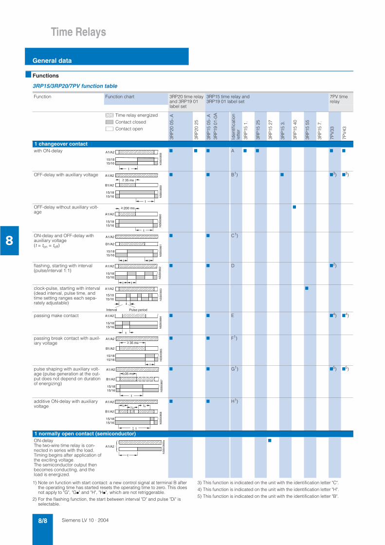
Functions
3RP15/3RP20/7PV function table
1) Note on function with start contact: a new control signal at terminal B after the operating time has started resets the operating time to zero. This does not apply to "G", "G!" and "H", "H!", which are not retriggerable.
2) For the flashing function, the start between interval "D" and pulse "Di" is selectable.
3) This function is indicated on the unit with the identification letter "C".
4) This function is indicated on the unit with the identification letter "H".
5) This function is indicated on the unit with the identification letter "B".
Function Function chart 3RP20 time relay and 3RP19 01 label set
3RP15 time relay and 3RP19 01 label set
7PV time relay
Time relay energized
Contact closed
Contact open
3RP
20 0
5-.A
3RP
20 2
5
3RP
15 0
5-.A
3RP
19 0
1-0A
Iden
tific
atio
nle
tter
3RP
15 1
.
3RP
15 2
5
3RP
15 2
7
3RP
15 3
.
3RP
15 4
0
3RP
15 5
5
3RP
15 7
.
7PV
33
7PV
43
1 changeover contactwith ON-delay 7 7 7 A 7 7 7 7
OFF-delay with auxiliary voltage 7 7 B1) 7 73) 7
3)
OFF-delay without auxiliary volt-age
7
ON-delay and OFF-delay with auxiliary voltage(t = ton = toff)
7 7 C1)
flashing, starting with interval(pulse/interval 1:1)
7 7 D 72)
clock-pulse, starting with interval (dead interval, pulse time, and time setting ranges each sepa-rately adjustable)
7
passing make contact 7 7 E 74) 7
4)
passing break contact with auxil-iary voltage
7 7 F1)
pulse shaping with auxiliary volt-age (pulse generation at the out-put does not depend on duration of energizing)
7 7 G1) 75) 7
5)
additive ON-delay with auxiliary voltage
7 7 H1)
1 normally open contact (semiconductor)ON-delayThe two-wire time relay is con-nected in series with the load. Timing begins after application of the exciting voltage. The semiconductor output then becomes conducting, and the load is energized.
7
A1/A2
15/1815/16
t
35 ms
NS
B00
859B1/A2
>
15/16
A1/A2
200 ms
t
15/18
NS
B00
860
>
tt
NS
B00
861
15/16
A1/A2
15/18
B1/A2
NS
B00
862
t t
15/16
A1/A2
15/18
NS
B00
864
t
A1/A2
15/1815/16
t
NS
B00
865
35 ms>A1/A2
15/1815/16
B1/A2
t
NS
B00
867
>A1/A2
15/1815/16
B1/A2
35 ms
t
NS
B00
868
t1 t2t3
A1/A2
15/1815/16
B1/A2

Siemens LV 10 · 2004 8/9
Time Relays
General data
8
1) Note on function with start contact: a new control signal at terminal B after the operating time has started resets the operating time to zero. This does not apply to G, G! and H, H!, which are not retriggerable.
Function Function chart 3RP20 time relay and 3RP19 01 label set
3RP15 time relay and 3RP19 01 label set
7PV
Time relay energized
Contact closed
Contact open
3RP
20 0
5-.B
3RP
20 2
5
3RP
15 0
5-.B
3RP
19 0
1-0B
3RP
15 0
5-.R
3RP
19 0
1-0A
Iden
tific
atio
nle
tter
3RP
15 1
.
3RP
15 2
5
3RP
15 2
7
3RP
15 3
.
3RP
15 4
0
3RP
15 5
5
3RP
15 6
0
3RP
15 7
.
7PV
41
2 changeover contactswith ON-delay 7 7 7 A 7 7
ON-delay and instantaneous contact
7 7 A! 7
OFF-delay with auxiliary voltage 7 7 7 B1)
OFF-delay with auxiliary voltage and instantaneous contact
7 7 B!1)
OFF-delay without auxiliary volt-age
7
ON-delay and OFF-delay with aux-iliary voltage (t = ton = toff)
7 7 7 C1)
ON-delay and OFF-delay with aux-iliary voltage and instantaneous contact (t = ton = toff)
7 7 C!1)
flashing, starting with interval(pulse/interval)
7 7 7 D
flashing, starting with interval(pulse/interval 1:1) and instantaneous contact
7 7 D!
passing make contact 7 7 7 E
passing make contact and instan-taneous contact
7 7 E!
t
NS
B00
871
A1/A2
15/1815/16
25/2825/26
15/1815/16
t
A1/A2
NS
B00
872
21/2421/22
t
NS
B00
873
>A1/A2
15/1815/16
B1/A2
25/2825/26
35 ms
!
"
#
15/16
A1/A2
200 ms
t
15/18
25/2825/26 N
SB
0087
5
>
15/1815/16
t
25/2825/26
A1/A2
B1/A2
t
NS
B00
876
15/1815/16
t21/2421/22
A1/A2
B1/A2
t
NS
B00
877
15/1815/16
t
A1/A2
25/2825/26
t
NS
B00
878
15/1815/16
21/2421/22
NS
B00
879A1/A2
t t
15/1815/16
t
A1/A2
25/2825/26
NS
B00
880
15/1815/16
21/2421/22
NS
B00
881A1/A2
t

Siemens LV 10 · 20048/10
Time Relays
General data
8
1) Note on function with start contact: a new control signal at terminal B after the operating time has started resets the operating time to zero. This does not apply to G, G! and H, H!, which are not retriggerable.
2) For function diagrams showing the various possibilities of operation of the 3RP15 60-1S.30 (see Page 8/11).
Function Function chart 3RP20 time relay and 3RP19 01 label set
3RP15 time relay and 3RP19 01 label set
Time relay energized
Contact closed
Contact open
3RP
20 0
5-.B
3RP
20 2
5
3RP
15 0
5-.B
3RP
19 0
1-0B
3RP
15 0
5-.R
3RP
19 0
1-0A
Iden
tific
atio
nle
tter
3RP
15 1
.
3RP
15 2
5
3RP
15 2
7
3RP
15 3
.
3RP
15 4
0
3RP
15 5
5
3RP
15 6
0
3RP
15 7
.
2 changeover contactspassing break contact with auxil-iary voltage
7 7 7 F1)
passing break contact with auxil-iary voltage and instantaneous contact
7 7 F!1)
pulse shaping with auxiliary volt-age (pulse generation at the output does not depend on duration of energizing)
7 7 7 G1)
pulse shaping with auxiliary volt-age and instantaneous contact(pulse generation at the output does not depend on duration of energizing)
7 7 G!1)
additive ON-delay with auxiliary voltage
7 H1)
additive ON-delay with auxiliary voltage and instantaneous contact
7 7 H!1)
star-delta function 7 7 *∆
2 normally open contactsstar-delta function *∆ 7
3 normally open contactsstar-delta function with overtravel function2)(idling)
7
15/1815/16
t
25/28
35ms
NS
B00
882
25/26
B1/A2
A1/A2
15/1815/16
t
35ms
21/2421/22
NS
B00
883A1/A2
B1/A2
>
15/1815/16
t
25/2825/26
A1/A2
B1/A2
35ms
NS
B00
884
15/1815/16
21/2421/22
A1/A2
B1/A2
t
NS
B00
885
35ms>
; ;
; ;
) ;
) ;
t
A1/A2
50ms
17/18
27/28
NS
B00
888
t 50 ms
NS
B00
889A1/A2
17/1817/28
!
"
"
"
$

Siemens LV 10 · 2004 8/11
Time Relays
General data
8
3RP15 function table
Possibilities of operation of the 3RP15 60-1S.30 time relay
Time relay energized
Contact closed
Contact open
tY = star time 1 to 20 s
tIdling = idling time (overtravel time) 30 to 600 s
Operation 1 Operation 1:
Start contact B./A2 is opened when supply voltage A./A2 is applied.
The supply voltage is applied to A./A2 and there is no control signal on B./A2. This starts the *∆timing. The idling time (overtravel time) is started by applying a control signal to B./A2. When the set time tIdling (30 to 600 s) has elapsed, the output relays (17/16 and 17/28) are reset. If the control signal on B./A2 is switched off (minimum OFF period 270 ms), a new timing is started.
Notes:
Observe response time (dead time) of 400 ms on energizing supply voltage until contacts 17/18 and 17/16 close.
Operation 2:
Start contact B./A2 is closed when supply voltage A./A2 is applied.
If the control signal B./A2 is already present when the supply voltage A./A2 is applied, no timing is started. The timing is only started when the control signal B./A2 is switched off.
Operation 3:
Start contact B./A2 closes while star time is running.
If the control signal B./A2 is applied again during the star time, the idling time starts and the timing is terminated normally.
Operation 4:
Start contact B./A2 opens while delta time is running and is applied again.
If the control signal on B./A2 is applied and switched off again during the delta time although the idling time has not yet elapsed, the idling time (overtravel time) is reset to zero. If the control signal is re-applied to B./A2, the idling time is restarted.
Application example based on standard operation (operation 1)
For example, use of 3RP15 60 for compressor control
Frequent starting of compressors strains the network, the machine, and the increased costs for the operator. The new time relay prevents fre-quent starting at times when there is high demand for compressed air. A special control circuit prevents the compressor from being switched off immediately when the required air pressure in the tank has been reached. Instead, the valve in the intake tube is closed and the com-pressor runs in idling mode for a specific time which can be set from 30 to 600 s.
If the pressure falls within this time, the motor does not have to be restarted again, but can return to nominal load operation from no-load operation.
If the pressure does not fall within this idling time, the motor is switched off.
The pressure switch controls the timing via B./A2.
The supply voltage is applied to A./A2 and the start contact B./A2 is open, i.e. there is no control signal on B./A2 when the supply voltage is applied. The pressure switch signals "too little pressure in system" and starts the timing via terminal B./A2. The compressor is started, enters *∆ operation, and fills the pressure tank.
When the pressure switch signals "sufficient pressure", the control signal B./A2 is applied, the idling time (overtravel time) is started, and the compressor enters no-load operation for the set period of time between 30 to 600 s. The compressor is then switched off. The compressor is only restarted if the pressure switch responds again (low pressure).
Operation 2
Operation 3
Operation 4
The following applies to all operations: the pressure switch controls the timing via B./A2.
%
%
"&
"
"
& $ ! & ! $ !
%
%
"&
"
"
&
! $
%
%
"&
"
"
&
! $
%
%
"&
"
"
& $ ' $ ' $ !

Siemens LV 10 · 20048/12
Time Relays
General data
8
Circuit diagrams
Internal circuit diagrams (terminal designation to DIN 46199, Part 5)3RP15 05-.A3RP15 13RP15 25-.A3RP20 053RP20 25
3RP15 05-.A3RP15 3-.A3RP20 05
3RP15 05-.A3RP20 05
3RP15 05-.A3RP20 05
with ON-delay OFF-delay with auxiliary voltage ON-delay and OFF-delay with aux-iliary voltage
flashing
3RP15 05-.A3RP20 05
3RP15 05-.A3RP20 05
3RP15 05-.A3RP20 00
3RP15 05-.A
passing make contact passing break contact with auxil-iary voltage
pulse-forming with auxiliary voltage additive ON-delay with auxiliary volt-age
3RP15 27
U = AC/DC 24 ... 66 V
AC/DC 90 ... 240 V
3RP15 40-.A 3RP15 55 3RP15 05-.AW30
ON-delay, two-wire design OFF-delay without auxiliary voltage clock-pulse relay multi-function relay (same functions as 3RP15 05-1A)
3RP15 05-.B, 3RP15 25-1B 3RP15 05-.B 3RP15 05-.B 3RP15 05-.B
ON-delay, 3RP15 25-1B also for AC/DC 42...48/60 V (see Page 8/13 3RP15 25-1BR30)
OFF-delay with auxiliary voltage ON-delay and OFF-delay with aux-iliary voltage
flashing
3RP15 05-.B 3RP15 05-.B 3RP15 05-.B 3RP15 05-.B
passing make contact passing break contact with auxil-iary voltage
pulse-forming with auxiliary voltage additive ON-delay with auxiliary volt-age and instantaneous contact
"
()(*
("*(*
()(*
("*(*
()(*
("*(*
()(*
("*(*
+
()(*
("*(*
()(*
("*(*
()(*
("*(*
()(*
("*(*
,
()(-*()( -*
.
()("*()(*
()(*
"
("*(*
+
()(*
()(*()(*%%%*
()(%%%*
()(*
("*(*
()(*
("*(*
()(*
("*(*
()(*
("*(*
++
()(*
("*(*
()(*
("*(*
()(*
("*(*
()(*
("*(*

Siemens LV 10 · 2004 8/13
Time Relays
General data
8
3RP15 05-.B 3RP15 05-.B 3RP15 05-.B 3RP15 05-.B
ON-delay and instantaneous con-tact
OFF-delay with auxiliary voltage and instantaneous contact
ON-delay and OFF-delay with auxil-iary voltage and instantaneous con-tact
flashing and instantaneous con-tact
3RP15 05-.B 3RP15 05-.B 3RP15 05-.B 3RP15 05-.B
passing make contact and instan-taneous contact
passing break contact with auxil-iary voltage and instantaneous contact
pulse-forming with auxiliary voltage and instantaneous contact
star-delta function
3RP15 74, 3RP15 76 3RP15 40-.B 3RP15 05-.BW30/-1BT20/-.RW30 3RP15 25-. BR30
star-delta time relay OFF-delay without auxiliary voltage multi-function relay (for functions see function table)
with ON-delay
3RP15 25-. BW30 3RP15 60-. S
with ON-delay star delta time relay with overtravel function (idling)
7PV33 48-2AX34 7PV33 48-2AX34 7PV33 48-2AX34 7PV33 48-2AX34
ON-delay (A) OFF-delay with auxiliary voltage (C)
passing make contact (H) pulse-forming with auxiliary volt-age (B)
7PV33 48-2AX34 7PV33 48-2AX34
. Important!
The terminal designations for 7PV are different from the desig-nations for the 3RP1 terminals.flashing, starting with interval (D) flashing, starting with pulse (Di)
()(*
("*(*
"
()(*
("*(*
()(*
("*(*
()(*
("*(*
+
()(*
("*(*
()(*
("*(*
()(*
("*(*
&
"
()(*
("*(*
"
& "
()(*
("*(*

Siemens LV 10 · 20048/14
Time Relays
General data
8 Position of the connection terminals
7PV41 48-1BG307PV41 48-1BP30
7PV41 48-1BG307PV41 48-1BP30
7PV43 48-1AG307PV43 48-1AP30
7PV43 48-1AG307PV43 48-1AP30
ON-delay (0) ON-delay and instantaneous con-tact (1)
ON-delay (A) OFF-delay with auxiliary voltage (C)
7PV43 48-1AG307PV43 48-1AP30
7PV43 48-1AG307PV43 48-1AP30
. Important!The terminal designations for 7PV are different from the designations for the 3RP1 terminals
passing make contact (H) pulse-forming with auxiliary voltage (B)
15
A2 1816
A1 25
28 NS
B01
115
26
AC 110VAC 240V
10
10 7
7
2 1 11
AC/DC 24V
10 4 3 87 9
15
A2 1816
A1 21
24 NS
B01
116
22
AC 110VAC 240V
10
10 7
7
2 1 11
AC/DC 24V
10 4 3 87 9
15
A2 1816
A1
NS
B01
117
AC 110VAC 240V
10
10 11
11
2 1
AC/DC 24V
10 4 311
B15
15
A2 1816
A1
NS
B01
118
AC 110VAC 240V
10
10 11
11
2 1
AC/DC 24V
10 4 311
B15
NS
B01
119
A1 15
A2 1816
B12 5
10 4 3
1
11
AC 110VAC 240V
10
10 11
11AC/DC 24V
NS
B01
120
A1 15
A2 1816
B12 5
10 4 3
1
11
AC 110VAC 240V
10
10 11
11AC/DC 24V
3RP20 05-.A 3RP20 25-.A 3RP20 05-.BW30
3RP15 05-1A
.
3RP15 05-1AW 3RP15 05-1B. 3RP15 05-1BT 3RP15 05-1BW 3RP15 05-1RW

Siemens LV 10 · 2004 8/15
Time Relays
General data
8
Position of the connection terminals
Note: all the diagrams show the view onto the connection terminals.
3RP15/3RP20/7PV circuit diagrams
The 17/18 contact is only closed on the star level;it is open on the delta level as well as when the power is switched off.
1) Depending on the version.
3RP15 1 3RP15 25-1A. or -1B. 1) 3RP15 27 3RP15 3. 3RP15 40
3RP15 55 3RP15 60 3RP15 7. LZX socket: MR78750 Socket 7PX9921 for time relays 7PV33; 7PV4. for time relays 7PV33; 7PV4.
Control circuits (example circuits) with 3RP15 74 and 3RP15 76 star-delta time relays
Control circuit (example circuit) with 3RP15 60 star-delta time relays
for pushbutton operation for maintained-contact operation
Size S00 to S3 Size S00 to S3
Legend:S0 button "OFF"S1 button "ON"S maintained-contact buttonK1 line contactorK2 star contactorK3 delta contactorK4 timer or time relayF0 fuseF1 overload relayP1 pressure switch
Siemens LV 10 · 20048/16
Time Relays
General data
8
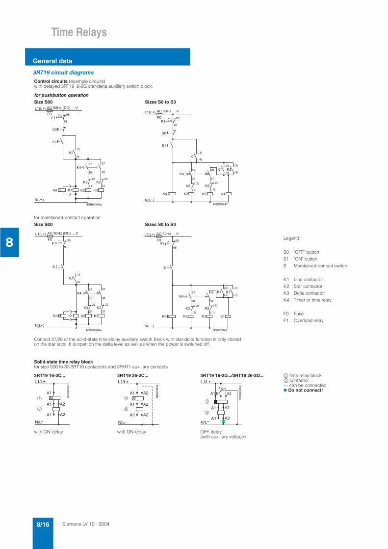
3RT19 circuit diagrams
Control circuits (example circuits) with delayed 3RT19 .6-2G star-delta auxiliary switch block.
for pushbutton operationSize S00 Sizes S0 to S3
for maintained-contact operation
Size S00 Sizes S0 to S3
Legend:
S0
S1
S
K1
K2
K3
K4
F0
F1
"OFF" button
"ON" button
Maintained-contact switch
Line contactor
Star contactor
Delta contactor
Timer or time relay
Fuse
Overload relay
Contact 27/28 of the solid-state time-delay auxiliary switch block with star-delta function is only closed on the star level. It is open on the delta level as well as when the power is switched off.
Solid-state time relay blockfor size S00 to S3 3RT10 contactors and 3RH11 auxiliary contacts
3RT19 16-2C... 3RT19 26-2C... 3RT19 16-2D.../3RT19 26-2D... $ time relay block% contactor--- can be connected Do not connect!
with ON-delay with ON-delay OFF-delay (with auxiliary voltage)

Siemens LV 10 · 2004 8/17
Time Relays
Time relays in 22.5 mm industrial enclosure
8
Overview
Standards
The time relays comply with: • EN 60721-3-3 "Environmental conditions"• EN 61812-1 (VDE 0435 Part 2021) "Solid-state relays, time re-
lays"• EN 61000-6-2 and EN 61000-6-4 "Electromagnetic compatibil-
ity"• EN 60947-5-1 (VDE 0660 Part 200) "Low-voltage controlgear,
switchgear and systems – Electromechanical controlgear"
3RP15 time relays, width 22.5 mm
Accessories
Push-in lugs for screw mounting
Sealable cover
Label set for marking the multifunction relay
Area of application
Time relays are used in control, starting, and protective circuits for all switching operations involving time delays. They guaran-tee a high level of functionality and a high repeat accuracy of timer settings.
Casing design
All time relays are suitable for snap-on mounting onto 35 mm standard mounting rails to EN 60715 or for screw fixing.
Functions
• Changing the time setting ranges and the functions are only ef-fective when carried out in de-energized state.
• Start input B1 or B3 must only be triggered when the supply voltage is applied.
• The same potential must be applied to A1 and B1 or A3 and B3. With two-voltage versions, only one voltage range must be connected.
• The activation of loads parallel to the start input is not permis-sible when using AC control voltage (see circuit diagrams).
• Surge suppression is integrated in the time relay. This prevents the generation of voltage peaks on the supply voltage when the relay is switched on and off. No damping measures are inte-grated at the contacts.
• 3RP15 05-.R must not be operated next to heat sources > 60 °C.
Parallel load on start input
L1
S1
K2A1
A2K1
NNSB00895
B1

Siemens LV 10 · 20048/18
Time Relays
Time relays in 22.5 mm industrial enclosure
8
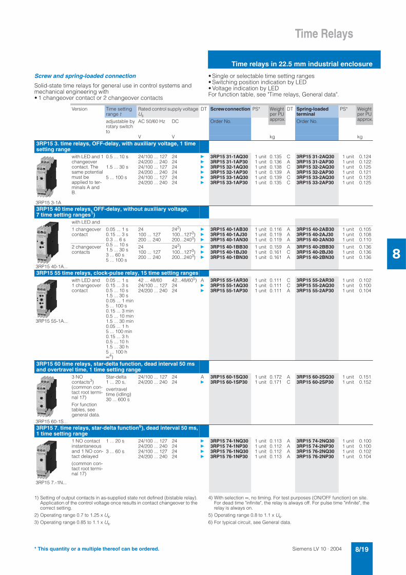
Selection and ordering data
Screw-type and spring-loaded connection
Solid-state time relays for general use in control systems and mechanical engineering with • 1 changeover contact or 2 changeover contacts
• Single or selectable time setting ranges• Switching position indication by LED• Voltage indication by LED For function table, see General data.
1) For functions, see 3RP19 01-0. label set.
2) At switch position ∞, no timing. For test purposes (ON/OFF function) on site. Relay is constantly on when activated, or relay remains constantly off when activated. Depending on which function is set.
3) Operating range 0.8 to 1.1 x Us.
4) Operating range 0.7 to 1.1 x Us.
5) Positively driven: NO and NC are never closed simultaneously; contact gap ≥ 0.5 mm is ensured, minimum make-break capacity 12 V, 3 mA.
6) The changeover contacts are actuated simultaneously, as a result of which only 8 functions are selectable (no star-delta, no instantaneous contact).
Version Time setting range t
Rated control supply voltage Us
DT Screw connection PS* Weight per PU approx.
DT Spring-loadedterminal
PS* Weight per PU approx.AC 50/60 Hz DCadjustable by
rotary switch to
Order No. Order No.
V V kg kg3RP15 05 time relays, multifunction, 15 time setting ranges
The functions can be adjusted by means of rotary switches. Indicator labels can be used to adjust different functions of the 3RP15 05 time relay clearly and unmistakably. The corresponding labels can be ordered as an accessory. The same potential must be applied to terminals A. and B.1)
3RP15 05-1B
with LED and
1 changeover contact,8 functions
0.05 ... 1 s 0.15 ... 3 s0.5 ... 10 s 1.5 ... 30 s 0.05 ... 1 min 5 ... 100 s 0.15 ... 3 min 0.5 ... 10 min 1.5 ... 30 min 0.05... 1 h 5 ...100 min 0.15... 3 h 0.5 ... 10 h1.5 ... 30 h 5 ...100 h∞2)
- 12 A 3RP15 05-1AA40 1 unit 0.120 C 3RP15 05-2AA40 1 unit 0.14524/100 ... 127 24 3RP15 05-1AQ30 1 unit 0.140 A 3RP15 05-2AQ30 1 unit 0.12524/200 ... 240 24 3RP15 05-1AP30 1 unit 0.141 A 3RP15 05-2AP30 1 unit 0.12624 ... 2404) 24 ... 2404)
3RP15 05-1AW30 1 unit 0.132 A 3RP15 05-2AW30 1 unit 0.1322 changeover contacts,16 functions
24/100 ... 127 24 3RP15 05-1BQ30 1 unit 0.158 A 3RP15 05-2BQ30 1 unit 0.13324/200 ... 240 24 3RP15 05-1BP30 1 unit 0.161 A 3RP15 05-2BP30 1 unit 0.13724 ... 2404) 24 ... 2404)
3RP15 05-1BW30 1 unit 0.164 A 3RP15 05-2BW30 1 unit 0.143400 ... 440 - 3RP15 05-1BT20 1 unit 0.169 –
2 changeover contacts, posi-tively driven and hard gold-plated8 functions5)6)
24 ... 240 24 ... 240 3RP15 05-1RW30 1 unit 0.163 A 3RP15 05-2RW30 1 unit 0.143
3RP15 1. time relays, ON-delay, 1 time setting range
3RP15 1-1A
with LED and 1 changeover contact
0.5 ... 10 s 24/100 ... 127 24 3RP15 11-1AQ30 1 unit 0.104 A 3RP15 11-2AQ30 1 unit 0.09224/200 ... 240 24 3RP15 11-1AP30 1 unit 0.105 A 3RP15 11-2AP30 1 unit 0.106
1.5 ... 30 s 24/100 ... 127 24 3RP15 12-1AQ30 1 unit 0.104 A 3RP15 12-2AQ30 1 unit 0.09224/200 ... 240 24 3RP15 12-1AP30 1 unit 0.104 A 3RP15 12-2AP30 1 unit 0.090
5 ... 100 s 24/100 ... 127 24 3RP15 13-1AQ30 1 unit 0.104 C 3RP15 13-2AQ30 1 unit 0.09424/200 ... 240 24 3RP15 13-1AP30 1 unit 0.103 A 3RP15 13-2AP30 1 unit 0.094
3RP15 25 time relays, ON-delay, 15 time setting ranges
3RP15 25-1A...
with LED and
1 changeover contact
0.05 ... 1 s 0.15 ... 3 s 0.5 ... 10 s 1.5 ... 30 s 0.05 ... 1 min 5 ... 100 s 0.15 ... 3 min 0.5 ... 10 min 1.5 ... 30 min 0.05 ... 1 h 5 ... 100 min 0.15 ... 3 h 0.5 ... 10 h 1.5 ... 30 h5 ... 100 h∞2)
24/100 ... 127 24 3RP15 25-1AQ30 1 unit 0.105 C 3RP15 25-2AQ30 1 unit 0.09524/200 ... 240 24 3RP15 25-1AP30 1 unit 0.104 A 3RP15 25-2AP30 1 unit 0.093
2 changeover contacts
42 ... 48/60 42...48/603) 3RP15 25-1BR30 1 unit 0.152 C 3RP15 25-2BR30 1 unit 0.12724/100 ... 127 24 3RP15 25-1BQ30 1 unit 0.152 C 3RP15 25-2BQ30 1 unit 0.12824/200 ... 240 24 3RP15 25-1BP30 1 unit 0.152 A 3RP15 25-2BP30 1 unit 0.12724 ... 2403) 24 ... 2404)
3RP15 25-1BW30 1 unit 0.159 A 3RP15 25-2BW30 1 unit 0.134
3RP15 27 time relays, ON-delay, two-wire design, 4 time setting ranges
3RP15 27-1E...
1 NO contact (semiconductor)
0.05 ... 1 s0.2 ...4 s1.5 ... 30 s12 ... 240 s
24 ... 66 24...663) 3RP15 27-1EC30 1 unit 0.099 C 3RP15 27-2EC30 1 unit 0.090
90 ... 240 90...2404) 3RP15 27-1EM30 1 unit 0.100 C 3RP15 27-2EM30 1 unit 0.090
* This quantity or a multiple thereof can be ordered.
Siemens LV 10 · 2004 8/19
Time Relays
Time relays in 22.5 mm industrial enclosure
8
Screw and spring-loaded connection
Solid-state time relays for general use in control systems and mechanical engineering with • 1 changeover contact or 2 changeover contacts
• Single or selectable time setting ranges • Switching position indication by LED • Voltage indication by LED For function table, see "Time relays, General data".
1) Setting of output contacts in as-supplied state not defined (bistable relay). Application of the control voltage once results in contact changeover to the correct setting.
2) Operating range 0.7 to 1.25 x Us.
3) Operating range 0.85 to 1.1 x Us.
4) With selection ∞, no timing. For test purposes (ON/OFF function) on site. For dead time "infinite", the relay is always off. For pulse time "infinite", the relay is always on.
5) Operating range 0.8 to 1.1 x Us.
6) For typical circuit, see General data.
Version Time setting range t
Rated control supply voltage Us
DT Screw connection PS* Weight per PU approx.
DT Spring-loadedterminal
PS* Weight per PU approx.AC 50/60 Hz DC Order No. Order No.adjustable by
rotary switch to
V V kg kg3RP15 3. time relays, OFF-delay, with auxiliary voltage, 1 time setting range
3RP15 3-1A
with LED and 1 changeovercontact. The same potential must be applied to ter-minals A and B.
0.5 ... 10 s 24/100 ... 127 24 3RP15 31-1AQ30 1 unit 0.135 C 3RP15 31-2AQ30 1 unit 0.12424/200 ... 240 24 3RP15 31-1AP30 1 unit 0.136 A 3RP15 31-2AP30 1 unit 0.122
1.5 ... 30 s 24/100 ... 127 24 3RP15 32-1AQ30 1 unit 0.138 C 3RP15 32-2AQ30 1 unit 0.12524/200 ... 240 24 3RP15 32-1AP30 1 unit 0.139 A 3RP15 32-2AP30 1 unit 0.121
5 ... 100 s 24/100 ... 127 24 3RP15 33-1AQ30 1 unit 0.139 C 3RP15 33-2AQ30 1 unit 0.12324/200 ... 240 24 3RP15 33-1AP30 1 unit 0.135 C 3RP15 33-2AP30 1 unit 0.125
3RP15 40 time relays, OFF-delay, without auxiliary voltage, 7 time setting ranges1)
3RP15 40-1A...
with LED and
1 changeover contact
0.05 ... 1 s 0.15 ... 3 s 0.3 ... 6 s 0.5 ... 10 s 1.5 ... 30 s 3 ... 60 s5 ... 100 s
24 242) 3RP15 40-1AB30 1 unit 0.116 A 3RP15 40-2AB30 1 unit 0.105100 ... 127 100...1273) 3RP15 40-1AJ30 1 unit 0.119 A 3RP15 40-2AJ30 1 unit 0.108200 ... 240 200...2403) 3RP15 40-1AN30 1 unit 0.119 A 3RP15 40-2AN30 1 unit 0.110
2 changeover contacts
24 242) 3RP15 40-1BB30 1 unit 0.159 A 3RP15 40-2BB30 1 unit 0.136100 ... 127 100...1273) 3RP15 40-1BJ30 1 unit 0.161 C 3RP15 40-2BJ30 1 unit 0.136200 ... 240 200...2403) 3RP15 40-1BN30 1 unit 0.161 A 3RP15 40-2BN30 1 unit 0.136
3RP15 55 time relays, clock-pulse relay, 15 time setting ranges
3RP15 55-1A...
with LED and1 changeover contact
0.05 ... 1 s 0.15 ... 3 s 0.5 ... 10 s 1.5 ... 30 s 0.05 ... 1 min 5 ... 100 s 0.15 ... 3 min 0.5 ... 10 min 1.5 ... 30 min 0.05 ... 1 h 5 ... 100 min 0.15 ... 3 h 0.5 ... 10 h 1.5 ... 30 h 5 ... 100 h∞4)
42 ... 48/60 42...48/605) A 3RP15 55-1AR30 1 unit 0.111 C 3RP15 55-2AR30 1 unit 0.10224/100 ... 127 24 3RP15 55-1AQ30 1 unit 0.111 C 3RP15 55-2AQ30 1 unit 0.10024/200 ... 240 24 3RP15 55-1AP30 1 unit 0.111 A 3RP15 55-2AP30 1 unit 0.104
3RP15 60 time relays, star-delta function, dead interval 50 ms and overtravel time, 1 time setting range
3RP15 60-1S...
3 NO contacts3)(common con-tact root termi-nal 17)
For function tables, see general data.
Star-delta 1 ... 20 s,
overtravel time (idling) 30 ... 600 s
24/100 ... 127 24 A 3RP15 60-1SQ30 1 unit 0.172 A 3RP15 60-2SQ30 1 unit 0.15124/200 ... 240 24 3RP15 60-1SP30 1 unit 0.171 C 3RP15 60-2SP30 1 unit 0.152
3RP15 7. time relays, star-delta function6), dead interval 50 ms, 1 time setting range
3RP15 7.-1N...
1 NO contact instantaneousand 1 NO con-tact delayed
(common con-tact root termi-nal 17)
1 ... 20 s 24/100 ... 127 24 3RP15 74-1NQ30 1 unit 0.113 A 3RP15 74-2NQ30 1 unit 0.10024/200 ... 240 24 3RP15 74-1NP30 1 unit 0.112 A 3RP15 74-2NP30 1 unit 0.100
3 ... 60 s 24/100 ... 127 24 3RP15 76-1NQ30 1 unit 0.112 A 3RP15 76-2NQ30 1 unit 0.10224/200 ... 240 24 3RP15 76-1NP30 1 unit 0.113 A 3RP15 76-2NP30 1 unit 0.104
* This quantity or a multiple thereof can be ordered.
Siemens LV 10 · 20048/20
Time Relays
Time relays in 22.5 mm industrial enclosure
8
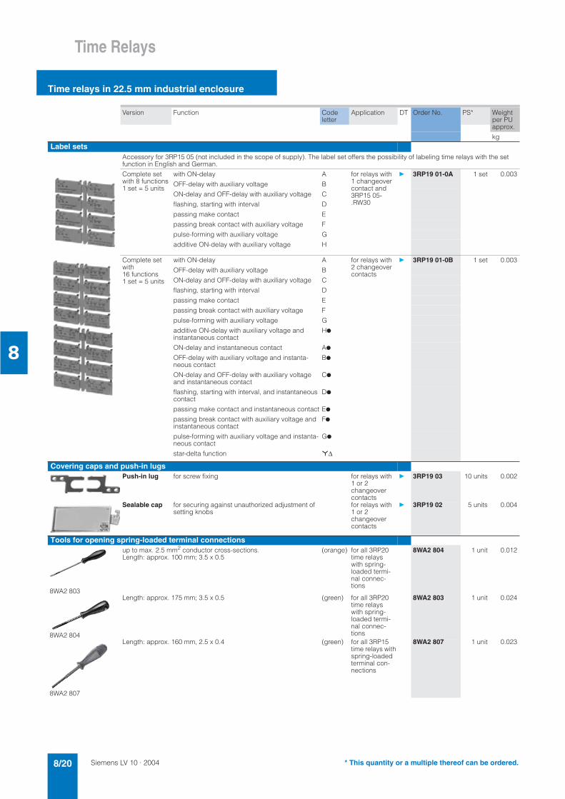
Version Function Codeletter
Application DT Order No. PS* Weight per PU approx.
kg
Label setsAccessory for 3RP15 05 (not included in the scope of supply). The label set offers the possibility of labeling time relays with the set function in English and German.
Complete set with 8 functions 1 set = 5 units
with ON-delay A for relays with1 changeover contact and 3RP15 05- .RW30
3RP19 01-0A 1 set 0.003
OFF-delay with auxiliary voltage B
ON-delay and OFF-delay with auxiliary voltage C
flashing, starting with interval D
passing make contact E
passing break contact with auxiliary voltage F
pulse-forming with auxiliary voltage G
additive ON-delay with auxiliary voltage H
Complete set with16 functions 1 set = 5 units
with ON-delay A for relays with2 changeover contacts
3RP19 01-0B 1 set 0.003
OFF-delay with auxiliary voltage B
ON-delay and OFF-delay with auxiliary voltage C
flashing, starting with interval D
passing make contact E
passing break contact with auxiliary voltage F
pulse-forming with auxiliary voltage G
additive ON-delay with auxiliary voltage and instantaneous contact
H
ON-delay and instantaneous contact A
OFF-delay with auxiliary voltage and instanta-neous contact
B
ON-delay and OFF-delay with auxiliary voltage and instantaneous contact
C
flashing, starting with interval, and instantaneous contact
D
passing make contact and instantaneous contact E
passing break contact with auxiliary voltage and instantaneous contact
F
pulse-forming with auxiliary voltage and instanta-neous contact
G
star-delta function *∆
Covering caps and push-in lugsPush-in lug for screw fixing for relays with
1 or 2 changeovercontacts
3RP19 03 10 units 0.002
Sealable cap for securing against unauthorized adjustment of setting knobs
for relays with 1 or 2 changeovercontacts
3RP19 02 5 units 0.004
Tools for opening spring-loaded terminal connections
8WA2 803
up to max. 2.5 mm2 conductor cross-sections. Length: approx. 100 mm; 3.5 x 0.5
(orange) for all 3RP20 time relays with spring-loaded termi-nal connec-tions
8WA2 804 1 unit 0.012
8WA2 804
Length: approx. 175 mm; 3.5 x 0.5 (green) for all 3RP20 time relays with spring-loaded termi-nal connec-tions
8WA2 803 1 unit 0.024
8WA2 807
Length: approx. 160 mm, 2.5 x 0.4 (green) for all 3RP15 time relays with spring-loaded terminal con-nections
8WA2 807 1 unit 0.023
* This quantity or a multiple thereof can be ordered.

Siemens LV 10 · 2004 8/21
Time Relays
45 mm SIRIUS Design time relays
8
Overview
Standards
The time relays comply with: • EN 60721-3-3 "Environmental conditions"• EN 61812-1 (VDE 0435 Part 2021) "Solid-state relays, time re-
lays"• EN 61000-6-2 and EN 61000-6-4 "Electromagnetic compatibil-
ity"• EN 60947-5-1 (VDE 0660 Part 200) "Low-voltage controlgear,
switchgear and systems – Electromechanical controlgear"• EN 61140 "Safe electrical isolation"
3RP20 time relay, width 45 mm
Accessories
Label set for marking the multifunction relay
Area of application
Time relays are used in control, starting, and protective circuits for all switching operations involving time delays. They guaran-tee a high level of functionality and a high repeat accuracy of timer settings.
Functions
• Changing the time setting ranges and the functions is only ef-fective when carried out in de-energized state.
• Start input B1 or B3 must only be triggered when the supply voltage is applied.
• The same potential must be applied to A1 and B1 or A3 and B3. With two-voltage version, only one voltage range must be connected.
• The activation of loads parallel to the start input is not permis-sible when using AC (see diagrams).
• Surge suppression is integrated in the time relay. This prevents the generation of voltage peaks on the supply voltage when the relay is switched on and off. No additional damping measures are necessary.
Time relay with multifunction
The functions can be adjusted by means of rotary switches. In-dicator labels can be used to adjust different functions of the 3RP20 05 time relay clearly and unmistakably. The correspond-ing labels can be ordered as an accessory. The same potential must be applied to terminals A. and B.
3RP20 05 with one changeover contact
corresponds to the functions of 3RP15 05-.A.
3RP20 05 with two changeover contacts
corresponds to the functions of 3RP15 05-.B.
Parallel load on start input
! " #
" #
$
L1
S1
K2A1
A2K1
NNSB00895
B1
Siemens LV 10 · 20048/22
Time Relays
45 mm SIRIUS Design time relays
8
Selection and ordering data
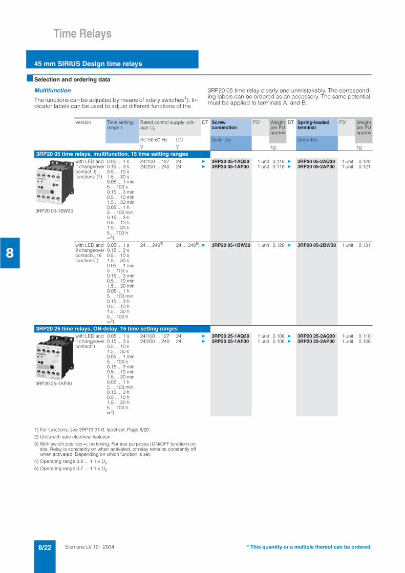
Multifunction
The functions can be adjusted by means of rotary switches1). In-dicator labels can be used to adjust different functions of the
3RP20 05 time relay clearly and unmistakably. The correspond-ing labels can be ordered as an accessory. The same potential must be applied to terminals A. and B..
1) For functions, see 3RP19 01-0. label set, Page 8/20.
2) Units with safe electrical isolation.
3) With switch position ∞, no timing. For test purposes (ON/OFF function) on site. Relay is constantly on when activated, or relay remains constantly off when activated. Depending on which function is set.
4) Operating range 0.8 ... 1.1 x Us.
5) Operating range 0.7 ... 1.1 x Us.
Version Time setting range t
Rated control supply volt-age Us
DT Screw connection
PS* Weight per PU approx.
DT Spring-loadedterminal
PS* Weight per PU approx.
Order No. Order No.AC 50-60 Hz DC
V V kg kg
3RP20 05 time relays, multifunction, 15 time setting ranges
3RP20 05-1BW30
with LED and1 changeover contact, 8 functions1)2)
0.05 ... 1 s 0.15 ... 3 s 0.5 ... 10 s 1.5 ... 30 s 0.05 ... 1 min 5 ... 100 s 0.15 ... 3 min 0.5 ... 10 min 1.5 ... 30 min 0.05 ... 1 h 5 ... 100 min 0.15 ... 3 h 0.5 ... 10 h 1.5 ... 30 h 5 ... 100 h∞3)
24/100 ... 127 24 3RP20 05-1AQ30 1 unit 0.118 3RP20 05-2AQ30 1 unit 0.12024/200 ... 240 24 3RP20 05-1AP30 1 unit 0.118 3RP20 05-2AP30 1 unit 0.121
with LED and 2 changeover contacts, 16 functions1)
0.05 ... 1 s 0.15 ... 3 s 0.5 ... 10 s 1.5 ... 30 s 0.05 ... 1 min 5 ... 100 s 0.15 ... 3 min 0.5 ... 10 min 1.5 ... 30 min 0.05 ... 1 h 5 ... 100 min 0.15 ... 3 h 0.5 ... 10 h 1.5 ... 30 h 5 ... 100 h∞3)
24 ... 2404) 24 ... 2405) 3RP20 05-1BW30 1 unit 0.128 3RP20 05-2BW30 1 unit 0.131
3RP20 25 time relays, ON-delay, 15 time setting ranges
3RP20 25-1AP30
with LED and 1 changeover contact2)
0.05 ... 1 s 0.15 ... 3 s 0.5 ... 10 s 1.5 ... 30 s 0.05 ... 1 min 5 ... 100 s 0.15 ... 3 min 0.5 ... 10 min 1.5 ... 30 min 0.05 ... 1 h 5 ... 100 min 0.15 ... 3 h 0.5 ... 10 h 1.5 ... 30 h 5 ... 100 h∞3)
24/100 ... 127 24 3RP20 25-1AQ30 1 unit 0.106 3RP20 25-2AQ30 1 unit 0.11024/200 ... 240 24 3RP20 25-1AP30 1 unit 0.106 3RP20 25-2AP30 1 unit 0.108
* This quantity or a multiple thereof can be ordered.
Siemens LV 10 · 2004 8/23
Time Relays
Time relays for front panel mounting
8
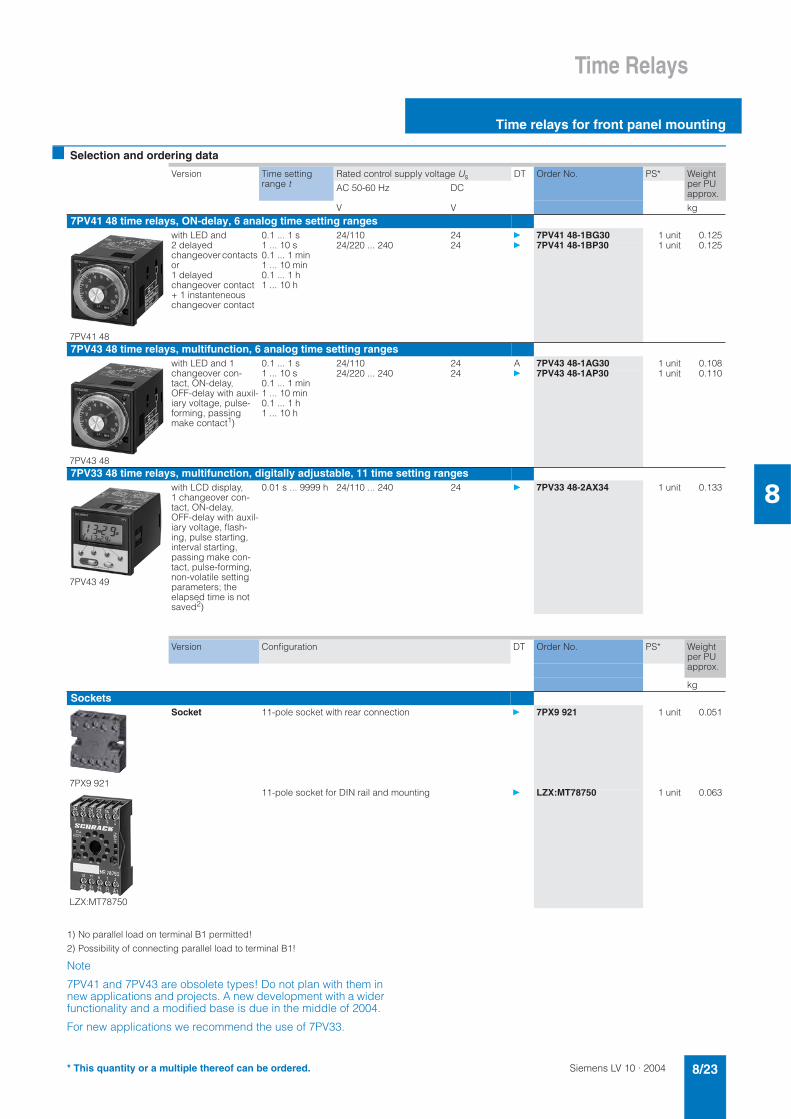
Selection and ordering data
1) No parallel load on terminal B1 permitted!
2) Possibility of connecting parallel load to terminal B1!
Note
7PV41 and 7PV43 are obsolete types! Do not plan with them in new applications and projects. A new development with a wider functionality and a modified base is due in the middle of 2004.
For new applications we recommend the use of 7PV33.
Version Time setting range t
Rated control supply voltage Us DT Order No. PS* Weight per PU approx.
AC 50-60 Hz DC
V V kg7PV41 48 time relays, ON-delay, 6 analog time setting ranges
7PV41 48
with LED and 2 delayed changeover contacts or1 delayed changeover contact+ 1 instanteneous changeover contact
0.1 ... 1 s 1 ... 10 s 0.1 ... 1 min 1 ... 10 min 0.1 ... 1 h 1 ... 10 h
24/110 24 7PV41 48-1BG30 1 unit 0.12524/220 ... 240 24 7PV41 48-1BP30 1 unit 0.125
7PV43 48 time relays, multifunction, 6 analog time setting ranges
7PV43 48
with LED and 1 changeover con-tact, ON-delay, OFF-delay with auxil-iary voltage, pulse-forming, passing make contact1)
0.1 ... 1 s 1 ... 10 s 0.1 ... 1 min 1 ... 10 min 0.1 ... 1 h 1 ... 10 h
24/110 24 A 7PV43 48-1AG30 1 unit 0.10824/220 ... 240 24 7PV43 48-1AP30 1 unit 0.110
7PV33 48 time relays, multifunction, digitally adjustable, 11 time setting ranges
7PV43 49
with LCD display, 1 changeover con-tact, ON-delay, OFF-delay with auxil-iary voltage, flash-ing, pulse starting, interval starting, passing make con-tact, pulse-forming, non-volatile setting parameters; the elapsed time is not saved2)
0.01 s ... 9999 h 24/110 ... 240 24 7PV33 48-2AX34 1 unit 0.133
Version Configuration DT Order No. PS* Weight per PU approx.
kgSockets
7PX9 921
Socket 11-pole socket with rear connection 7PX9 921 1 unit 0.051
LZX:MT78750
11-pole socket for DIN rail and mounting LZX:MT78750 1 unit 0.063
* This quantity or a multiple thereof can be ordered.

Siemens LV 10 · 20048/24
Time Relays
Time relays for mounting onto contactors
8
Selection and ordering data
1) The terminals for the rated control supply voltage are connected to the contactor beneath by the integrated spring-type contacts of the solid-state time-delay auxiliary switch block when mounting.
2) Setting of output contacts in as-supplied state not defined (bistable relay). Application of the control voltage once results in contact changeover to the correct setting.
3) The terminals A1 and A2 for the rated control supply voltage of the solid-state time-delay auxiliary switch block must be connected to the corre-sponding contactor by connecting leads.
for contac-tors
Auxiliary contacts Function
Rated control supply volt-age Us
Time setting range t DT Order No. PS* Weight per PU approx. Time relay energized
Time relay closedContact open
Type V S kgFor size S00,1) with screw connection
3RT19 16-2...
Terminal designations to EN 46199 Part 5
• ON-delay (varistor integrated)3RT10 1, 3RH11
1 NO + 1 NC AC/DC 24 0.05 ... 1 3RT19 16-2EJ11 1 unit 0.0850.5 ... 10 3RT19 16-2EJ21 1 unit 0.0845 ... 100 C 3RT19 16-2EJ31 1 unit 0.086
AC 100 ... 127 0.05 ... 1 C 3RT19 16-2EC11 1 unit 0.0870.5 ... 10 3RT19 16-2EC21 1 unit 0.0875 ... 100 3RT19 16-2EC31 1 unit 0.086
AC 200 ... 240 0.05 ... 1 A 3RT19 16-2ED11 1 unit 0.0880.5 ... 10 3RT19 16-2ED21 1 unit 0.0895 ... 100 3RT19 16-2ED31 1 unit 0.087
• OFF-delay without auxiliary voltage (varistor integrated)2)
1 NO + 1 NC AC/DC 24 0.05 ... 1 3RT19 16-2FJ11 1 unit 0.0870.5 ... 10 3RT19 16-2FJ21 1 unit 0.0865 ... 100 3RT19 16-2FJ31 1 unit 0.089
AC 100 ... 127 0.05 ... 1 C 3RT19 16-2FK11 1 unit 0.0860.5 ... 10 3RT19 16-2FK21 1 unit 0.0875 ... 100 C 3RT19 16-2FK31 1 unit 0.088
AC 200 ... 240 0.05 ... 1 A 3RT19 16-2FL11 1 unit 0.0890.5 ... 10 3RT19 16-2FL21 1 unit 0.0865 ... 100 3RT19 16-2FL31 1 unit 0.089
• OFF-delay with auxiliary voltage
1 changeover contact AC/DC 24 0.5 ... 10 B 3RT19 16-2LJ21 1 unit 0.060AC 100 ... 127 B 3RT19 16-2LC21 1 unit 0.062AC 200 ... 240 B 3RT19 16-2LD21 1 unit 0.063
• Star-delta function (varistor integrated)
1 NO, delayed + 1 NO, in-stantaneous, dead time 50 ms
AC/DC 24 1.5 ... 30 3RT19 16-2GJ51 1 unit 0.086AC 100 ... 127 D 3RT19 16-2GC51 1 unit 0.087AC 200 ... 240 3RT19 16-2GD51 1 unit 0.088
For sizes S0 to S123), with screw connection
3RT19 26-2...
• with ON-delay3RT10 2, 3RT10 3, 3RT10 4
1 NO + 1 NC AC/DC 24 0.05 ... 1 D 3RT19 26-2EJ11 1 unit 0.0810.5 ... 10 3RT19 26-2EJ21 1 unit 0.0815 ... 100 C 3RT19 26-2EJ31 1 unit 0.082
AC 100 ... 127 0.05 ... 1 C 3RT19 26-2EC11 1 unit 0.0830.5 ... 10 3RT19 26-2EC21 1 unit 0.0835 ... 100 D 3RT19 26-2EC31 1 unit 0.083
AC 200 ... 240 0.05 ... 1 D 3RT19 26-2ED11 1 unit 0.0850.5 ... 10 3RT19 26-2ED21 1 unit 0.0855 ... 100 C 3RT19 26-2ED31 1 unit 0.085
• OFF-delay without auxiliary voltage2)
1 NO + 1 NC AC/DC 24 0.05 ... 1 3RT19 26-2FJ11 1 unit 0.0830.5 ... 10 3RT19 26-2FJ21 1 unit 0.0845 ... 100 3RT19 26-2FJ31 1 unit 0.085
AC 100 ... 127 0.05 ... 1 D 3RT19 26-2FK11 1 unit 0.0870.5 ... 10 3RT19 26-2FK21 1 unit 0.0845 ... 100 C 3RT19 26-2FK31 1 unit 0.087
AC 200 ... 240 0.05 ... 1 D 3RT19 26-2FL11 1 unit 0.0860.5 ... 10 A 3RT19 26-2FL21 1 unit 0.0845 ... 100 3RT19 26-2FL31 1 unit 0.086
• star-delta function
1 NO, delayed + 1 NO, in-stantaneous, dead time 50 ms
AC/DC 24 1.5 ... 30 3RT19 26-2GJ51 1 unit 0.084AC 100 ... 127 3RT19 26-2GC51 1 unit 0.085
1 NO, delayed + 1 NO, in-stantaneous, dead time 50 ms
AC 200 ... 240 3RT19 26-2GD51 1 unit 0.088
t
NS
B00
933
A1/A2
27/28
35/36
t
NS
B00
934
A1/A2
27/28
35/36
200 ms>
t
NS
B00
935
A1/A2
Y 27/28
37/38
50 ms
NS
B00
936
A1/A2
-7/-8
-5/-6
t
t
NS
B00
937
-7/-8
-5/-6
200 ms>
A1/A2
t
NS
B00
938
A1/A2
Y -7/-8
-7/-850 ms
* This quantity or a multiple thereof can be ordered.

Siemens LV 10 · 2004 8/25
Time Relays
Time relays for mounting onto contactors
8
1) Not for 3RT10 4 contactor with 24 to 42 V rated control supply voltage.
for contactors Function Rated control supply voltage Us
Time setting range t
DT Order No. PS* Weight per PU approx.Time relay energized
Contact closedContact openContactor energized
Type V S kg
For size S00, with semiconductor output and screw connection for mounting onto the front of contactors
The electrical connection between the time-relay block and the contactor beneath is established automatically when it is snapped on.
3RT10 1, 3RH11
• ON-delay, two-wire version (varistor integrated)
3RT19 16-2C...
AC/DC 24 ... 66 0.05 ... 1 C 3RT19 16-2CG11 1 unit 0.0510.5 ... 10 3RT19 16-2CG21 1 unit 0.0515 ... 100 3RT19 16-2CG31 1 unit 0.054
AC/DC 90 ... 240 0.05 ... 1 A 3RT19 16-2CH11 1 unit 0.0470.5 ... 10 3RT19 16-2CH21 1 unit 0.0475 ... 100 3RT19 16-2CH31 1 unit 0.051
• OFF-delay with auxiliary voltage (varistor integrated)
3RT19 16-2D...
AC/DC 24 ... 66 0.05 ... 1 C 3RT19 16-2DG11 1 unit 0.0520.5 ... 10 C 3RT19 16-2DG21 1 unit 0.0525 ... 100 C 3RT19 16-2DG31 1 unit 0.057
AC/DC 90 ... 240 0.05 ... 1 D 3RT19 16-2DH11 1 unit 0.0530.5 ... 10 3RT19 16-2DH21 1 unit 0.0535 ... 100 C 3RT19 16-2DH31 1 unit 0.052
For sizes S0 to S3, with semiconductor output and screw connectionfor mounting onto coil terminals on top of the contactors
The electrical connection between the relay block and the corresponding con-tactor is established by screwing the two connecting pins of the time-relay block to coil terminals A1/A2 on top of the contactor.
3RT10 2, 3RT10 3, 3RT10 41)
• ON-delay, two-wire version (varistor integrated)
3RT19 26-2C...
AC/DC 24 ... 66 0.05 ... 1 A 3RT19 26-2CG11 1 unit 0.0480.5 ... 10 A 3RT19 26-2CG21 1 unit 0.0495 ... 100 C 3RT19 26-2CG31 1 unit 0.048
AC/DC 90 ... 240 0.05 ... 1 3RT19 26-2CH11 1 unit 0.0480.5 ... 10 3RT19 26-2CH21 1 unit 0.0475 ... 100 3RT19 26-2CH31 1 unit 0.048
• OFF-delay with auxiliary voltage (varistor integrated)
3RT19 26-2D...
AC/DC 24 ... 66 0.05 ... 1 D 3RT19 26-2DG11 1 unit 0.0500.5 ... 10 C 3RT19 26-2DG21 1 unit 0.0515 ... 100 D 3RT19 26-2DG31 1 unit 0.051
AC/DC 90 ... 240 0.05 ... 1 C 3RT19 26-2DH11 1 unit 0.0500.5 ... 10 A 3RT19 26-2DH21 1 unit 0.0505 ... 100 C 3RT19 26-2DH31 1 unit 0.050
!"#$#%&
'()'$
"*+
!"#$#%&
'()'$
!"#$#%&
'()'$
"*+
!"#$#%&
'()'$
* This quantity or a multiple thereof can be ordered.

Siemens LV 10 · 20048/26
Monitoring Relays
General data
Temperature Monitoring Relays
8
Overview
The SIMIREL temperature monitoring relays 3RS10 and 3RS11 can be used for measuring temperatures in solid, liquid and gas media. The temperature is sensed by the sensor in the medium, evaluated by the device and monitored for overshoot or under-shoot or for staying within an operating range (window function). The range comprises adjustable analog units with one or two threshold values, digital units to DIN 3440, which are also a good alternative to temperature controls for the low-end range, and digital units for up to 3 sensors which have been optimized for monitoring large motors.
Design
The temperature monitoring relays comply with:• IEC 60721-3-3 "Environmental conditions"• IEC 60947-5-1 "Low-voltage controlgear, switchgear and sys-
tems – Electromechanical controlgear"• EN 61000-6-4 "Basic technical standard for emitted interfer-
ence (Industry)"• EN 61000-6-2 "Basic technical standard for immunity to inter-
ference (Industry)"• DIN EN 50042 "Designations for terminals"• UL/CSA• DIN 3440 (3RS10 40, 3RS11 40, 3RS10 42, 3RS11 42).
Connection of resistance-type thermometers
2-wire measurement
When 2-wire temperature sensors are used, the resistances of the sensor and wiring are added. The resulting systematic error must be taken into account when the signal evaluator is cali-brated. A jumper must be clamped between terminals T2 and T3 for this purpose.
Wiring errors:
The errors that are generated by the wiring comprise approxi-mately 2.5 Kelvin/Ohm. If the resistance of the wiring is not known and cannot be measured, the wiring errors can also be estimated using the following table.
Temperature drift dependent on the length and cross-section of the leads with PT100 sensors and an ambient temperature of 20°C, in K:
3-wire measurement
To minimize the effects of the line resistances, a three-wire circuit is often used. Using the additional wire, two measuring circuits can be formed of which one is used as a reference. The signal evaluator can then automatically calculate the line resistance and take it into account.
Connection of thermocouples
Based on the thermo-electrical effect, a differential temperature measurement will be performed between the measuring point and the signal evaluator.
This principle assumes that the signal evaluator knows the tem-perature at the clamping point (T2). For this reason, the 3RS11 temperature monitoring relay has an integral compensator that determines this comparison temperature and builds it into the re-sult of the measurement.
The absolute temperature is therefore calculated from the ambi-ent temperature of the signal evaluator and the temperature dif-ference measured by the thermocouple.
Temperature detection is therefore possible (T1) without needing to know the precise ambient temperature of the clamping point at the signal evaluator (T2).
The connecting cable is only permitted to be extended using connecting leads that are made from the same material as the thermocouple. If a different type of conductor is used, an error will result in the measurement.
More information can be found on the Internet under
www.feldgeraete.de/76/produkte/fuw.html www.ephy-mess.de
or from
EPHY-MESS GmbH
-&./&"& &)2
G&?)&?+2&G
G&+1 ()*&%G
31 && ) ()*
0%) /+1
G4/%(G,&1
1 ()*0/.&& &+&)
Cable lengths in m
Cross-section in mm2
0.5 0.75 1 1.50 0.0 0.0 0.0 0.0
10 1.8 1.2 0.9 0.625 4.5 3.0 2.3 1.550 9.0 6.0 4.5 3.075 13.6 9.0 6.8 4.5
100 18.1 12.1 9.0 6.0200 36.3 24.2 18.1 12.1500 91.6 60.8 45.5 30.2

Siemens LV 10 · 2004 8/27
Monitoring RelaysTemperature Monitoring Relays
General data
8
Functions
Once the temperature has reached the set threshold ϑ1, the out-put relay K1 changes its output state as soon as the set time thas elapsed (K2 responds in the same manner to ϑ2). The time delay t can only be adjusted with digital units (the following ap-plies to analog units t = 0).
The relays return to their original state as soon as the tempera-ture reaches the set hysteresis value.
Temperature overshoot
Open-circuit principle
Closed-circuit principle
Temperature undershoot
Open-circuit principle
Closed-circuit principle
Window monitoring (digital units only)
Once the temperature has reached the upper threshold ϑ1, the output relay K1 changes its output state as soon as the set time t has elapsed. The relay returns to its original state as soon as the temperature reaches the set hysteresis value.
K2 responds in the same manner to the lower threshold of ϑ2.
Open-circuit principle
Closed-circuit principle
Principle of operation with memory function (3RS10 42, 3RS11 42), based on the example of temperature undershoot using the closed-circuit principle
Once the temperature has reached the upper threshold ϑ1, the output relay K1 changes its output state as soon as the set time t has elapsed. (K2 responds similarly to ϑ2.). The relay only re-turns to the original state when the temperature falls below the set hysteresis value and when terminals Y3 and Y4 have been briefly jumpered.
! "
#
#

Siemens LV 10 · 20048/28
Monitoring Relays
General data
Temperature Monitoring Relays
8
Characteristics
For thermocouples For resistance sensors
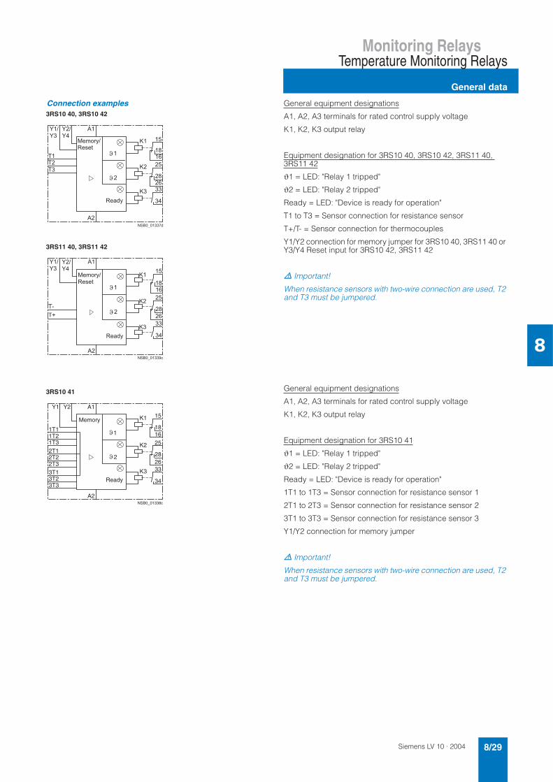
Circuit diagrams
Connection examples3RS10 00, 3RS10 10
3RS11 00, 3RS11 01
3RS10 20, 3RS10 30
3RS11 20, 3RS11 21
General equipment designations
A1, A2, A3 terminals for rated control supply voltage
K1, K2, K3 output relay
Equipment designation for 3RS10 00, 3RS10 10, 3RS11 00, 3RS11 01, 3RS10 20, 3RS10 30, 3RS11 20, 3RS11 21
= LED: "Device connected to supply"
ϑ1 = LED: "Relay 1 tripped"
ϑ2 = LED: "Relay 2 tripped"
T1 to T3 = Sensor connection for resistance sensor
T+/T- Sensor connection for thermocouples
. Important!
When resistance sensors with two-wire connection are used, T2 and T3 must be jumpered.
&(&
(
'
&
-&./&"&)D
9+
2&)
.9
-1/&GG -1/&GHG
-1/&G2G
-1/&GG
-1/&G-G
1
-&./&"&)D
&
)
&)*.
-
2-I( 2-I( -
-
Siemens LV 10 · 2004 8/29
Monitoring RelaysTemperature Monitoring Relays
General data
8
Connection examples 3RS10 40, 3RS10 42
3RS11 40, 3RS11 42
3RS10 41
General equipment designations
A1, A2, A3 terminals for rated control supply voltage
K1, K2, K3 output relay
Equipment designation for 3RS10 40, 3RS10 42, 3RS11 40, 3RS11 42
ϑ1 = LED: "Relay 1 tripped"
ϑ2 = LED: "Relay 2 tripped"
Ready = LED: "Device is ready for operation"
T1 to T3 = Sensor connection for resistance sensor
T+/T- = Sensor connection for thermocouples
Y1/Y2 connection for memory jumper for 3RS10 40, 3RS11 40 or Y3/Y4 Reset input for 3RS10 42, 3RS11 42
. Important!
When resistance sensors with two-wire connection are used, T2 and T3 must be jumpered.
General equipment designations
A1, A2, A3 terminals for rated control supply voltage
K1, K2, K3 output relay
Equipment designation for 3RS10 41
ϑ1 = LED: "Relay 1 tripped"
ϑ2 = LED: "Relay 2 tripped"
Ready = LED: "Device is ready for operation"
1T1 to 1T3 = Sensor connection for resistance sensor 1
2T1 to 2T3 = Sensor connection for resistance sensor 2
3T1 to 3T3 = Sensor connection for resistance sensor 3
Y1/Y2 connection for memory jumper
. Important!
When resistance sensors with two-wire connection are used, T2 and T3 must be jumpered.
!
A2NSB0_01338c
A1
K1 15
1618
K2 25
28
K3 33
34
26
Y2Y1
1T11T21T32T12T22T33T13T23T3
Memory
Ready
1
2

Siemens LV 10 · 20048/30
Monitoring Relays
Analog adjustable relays
Temperature Monitoring Relays
8
Overview
The analog SIMIREL temperature monitoring relays 3RS10 and 3RS11 can be used for measuring temperatures in solid, liquid and gas media. The temperature is sensed by the sensors in the medium, evaluated by the device and monitored for overshoot or undershoot. When the threshold values are reached, the output relay switches on or off depending on the setting.
Benefits
• All devices are available alternatively with spring-loaded termi-nals
• All units except for AC/DC 24 V feature electrical isolation• Extremely easy operation using a rotary potentiometer• Variable hysteresis• Adjustable working principle for devices with 2 thresholds.
Area of application
The analog SIMIREL temperature monitoring relays 3RS10 and 3RS11 can be used in almost any application in which tempera-ture overshoot or undershoot is not permitted, e.g.:
Monitoring of set temperature limit and output of alarm mes-sages for:• Motor and plant protection• Switchgear cabinet temperature monitoring• Freeze monitoring• Temperature limits for process variables e.g. in the packaging
industry or electroplating• Controlling equipment and machines such as heating, climate
and ventilation systems, solar collectors, heat pumps or warm water supplies.
• Bearing and gear oil monitoring.• Monitoring of coolants.

Siemens LV 10 · 2004 8/31
Monitoring RelaysTemperature Monitoring Relays
Analog adjustable relays
8
Technical specifications
1) 2-wire connection of resistance sensors with wire jumper between T2 and T3.
Type 3RS10 00 3RS10 10 3RS11 00 3RS11 01 3RS10 20 3RS10 30 3RS11 20 3RS11 21General dataThermistor type PT100 TC type J TC type K PT100 TC type J TC type K
Width mm 22,5
Operating range 0.85 ... 1.1 × Us
Rated power W/VA < 2/4Auxiliary circuitContacts 1 NO + 1 NC 1 CO + 1 NO
Rated operating currents Ie• AC-15 at 230 V AC, 50 Hz A 3• DC-13 at:
- 24 V A 1- 240 V A 0.1
DIAZED fuse• Operational class gl/Gg A 4Short-circuit current (at 250 V) kA 1
Electrical endurance AC-15 at 3 A
100.000
Mechanical endurancemechanical operating cycles
3 × 10⁶
Tripping unit• Measuring accuracy at 20 °C ambi-
ent temperature(T20)
typical < ± 5 % from upper limit of scale
• Reference point accuracy – < ± 5 K – < ± 5 K
• Deviations due to ambient tempera-turein % from measuring range
< 2 < 3 < 2 < 3
• Hysteresis settings- for temperature 1 2 to 20 % from upper limit of scale- for temperature 2 5 % from upper limit of scale
Sensor circuit • Typical sensor current
- PT100 typical 1 % – typical 1 % –
• Open-circuit detection no
• Short-circuit detection no
• 3-wire conductor connection1) yes – yes –EnclosureEnvironmental influencesPermissible ambient temperature °C – 25 ... 60Permissible storage temperature °C – 40 ... 80Permissible mounting position any
Degree of protection to EN 60529 Terminals: IP20; cover: IP40
Rated insulation voltage Ui(pollution degree 3)
V 300
Conductor cross-section• Screw connection M 3.5 (standard screwdriver, size 2 and Pozidriv 2)
- Solid mm2 1 × (0.5 ... 4)/2 × (0.5 ... 2.5)- Finely stranded, with end sleeves mm2 1 × (0.5 ... 2.5)/2 × (0.5 ... 1.5)- AWG conductors,
solid or strandedAWG 2 × (20 ... 14)
- Tightening torque Nm 0.8 ... 1.2• Spring-loaded terminal
- Solid mm2 2 × (0.25 ... 1.5)- Finely stranded, with end sleeve mm2 2 × (0.25 ... 1)- Finely stranded,
without end sleevesmm2 2 × (0.25 ... 1.5)
- AWG conductors, solid or stranded
AWG 2 × (24 ... 16)
- Corresponding opening tool 8WA2 807
Vibration resistance to IEC 60068-2-6 Hz/mm
5 ... 26/0.75
Shock resistance to IEC 60068-2-27 g/ms 15/11

Siemens LV 10 · 20048/32
Monitoring Relays
Analog adjustable relays
Temperature Monitoring Relays
8
Selection and ordering data
Analog adjustable evaluation units with one or two threshold values
For analog adjustable units, the threshold values and the hyster-esis of 2 to 20 % are set via a rotary potentiometer. For units with
2 threshold values, the adjustable hysteresis only applies to threshold value 1. For the second threshold value, a fixed hyster-esis of 5 % applies. The product range has been developed for applications where a setting accuracy of ±5 % is sufficient.
Sensor Func-tion
Measuringrange
Rated control sup-ply voltage UsAC 50-60 Hz
DT Screw connection PS* Weight per PU approx.
DT Spring-loadedterminal
PS* Weight per PU approx.Order No. Order No.
°C V kg kgAnalog adjustable, 1 threshold value, width 22.5 mm; closed-circuit principle; without memory; 1 NO + 1 NC
3RS10 00-1CD10
PT100 (resis-tancesensor)
Over-shoot
– 50 ... + 50 AC/DC 24 V A 3RS10 00-1CD00 1 unit 0.150 C 3RS10 00-2CD00 1 unit 0.125AC 110/230 V A 3RS10 00-1CK00 1 unit 0.190 C 3RS10 00-2CK00 1 unit 0.163
0 ... + 100 AC/DC 24 V A 3RS10 00-1CD10 1 unit 0.145 C 3RS10 00-2CD10 1 unit 0.125AC 110/230 V A 3RS10 00-1CK10 1 unit 0.189 C 3RS10 00-2CK10 1 unit 0.165
0 ... + 200 AC/DC 24 V A 3RS10 00-1CD20 1 unit 0.145 C 3RS10 00-2CD20 1 unit 0.121AC 110/230 V A 3RS10 00-1CK20 1 unit 0.186 C 3RS10 00-2CK20 1 unit 0.165
Under-shoot
– 50 ... + 50 AC/DC 24 V B 3RS10 10-1CD00 1 unit 0.150 C 3RS10 10-2CD00 1 unit 0.180AC 110/230 V B 3RS10 10-1CK00 1 unit 0.186 C 3RS10 10-2CK00 1 unit 0.180
0 ... + 100 AC/DC 24 V B 3RS10 10-1CD10 1 unit 0.150 C 3RS10 10-2CD10 1 unit 0.180AC 110/230 V A 3RS10 10-1CK10 1 unit 0.190 C 3RS10 10-2CK10 1 unit 0.180
0 ... + 200 AC/DC 24 V B 3RS10 10-1CD20 1 unit 0.150 C 3RS10 10-2CD20 1 unit 0.125AC 110/230 V B 3RS10 10-1CK20 1 unit 0.191 C 3RS10 10-2CK20 1 unit 0.165
Type J (thermo-couple)
Over-shoot
0 ... + 200 AC/DC 24 V B 3RS11 00-1CD20 1 unit 0.150 C 3RS11 00-2CD20 1 unit 0.125AC 110/230 V B 3RS11 00-1CK20 1 unit 0.190 C 3RS11 00-2CK20 1 unit 0.180
0 ... + 600 AC/DC 24 V C 3RS11 00-1CD30 1 unit 0.149 C 3RS11 00-2CD30 1 unit 0.125AC 110/230 V B 3RS11 00-1CK30 1 unit 0.190 C 3RS11 00-2CK30 1 unit 0.180
Type K (thermo-couple)
Over-shoot
0 ... + 200 AC/DC 24 V B 3RS11 01-1CD20 1 unit 0.150 C 3RS11 01-2CD20 1 unit 0.122AC 110/230 V B 3RS11 01-1CK20 1 unit 0.190 C 3RS11 01-2CK20 1 unit 0.180
0 ... + 600 AC/DC 24 V B 3RS11 01-1CD30 1 unit 0.150 C 3RS11 01-2CD30 1 unit 0.125AC 110/230 V B 3RS11 01-1CK30 1 unit 0.190 C 3RS11 01-2CK30 1 unit 0.180
+ 500 ... + 1000 AC/DC 24 V C 3RS11 01-1CD40 1 unit 0.150 C 3RS11 01-2CD40 1 unit 0.180AC 110/230 V B 3RS11 01-1CK40 1 unit 0.190 C 3RS11 01-2CK40 1 unit 0.180
Analog adjustable for warning and tripping (2 threshold values), width 22.5 mm; open/closed-circuit principle switch-able; without memory; 1 NO + 1 CO
3RS11 21-1DD40
PT100 (resis-tancesensor)
Over-shoot
– 50 ... + 50 AC/DC 24 V C 3RS10 20-1DD00 1 unit 0.166 C 3RS10 20-2DD00 1 unit 0.138AC/DC 24 ... 240 V A 3RS10 20-1DW00 1 unit 0.175 C 3RS10 20-2DW00 1 unit 0.149
0 ... + 100 AC/DC 24 V A 3RS10 20-1DD10 1 unit 0.164 C 3RS10 20-2DD10 1 unit 0.143AC/DC 24 ... 240 V A 3RS10 20-1DW10 1 unit 0.175 C 3RS10 20-2DW10 1 unit 0.149
0 ... + 200 AC/DC 24 V A 3RS10 20-1DD20 1 unit 0.166 C 3RS10 20-2DD20 1 unit 0.180AC/DC 24 ... 240 V A 3RS10 20-1DW20 1 unit 0.175 C 3RS10 20-2DW20 1 unit 0.180
Under-shoot
– 50 ... + 50 AC/DC 24 V A 3RS10 30-1DD00 1 unit 0.165 C 3RS10 30-2DD00 1 unit 0.180AC/DC 24 ... 240 V A 3RS10 30-1DW00 1 unit 0.174 C 3RS10 30-2DW00 1 unit 0.180
0 ... + 100 AC/DC 24 V A 3RS10 30-1DD10 1 unit 0.166 C 3RS10 30-2DD10 1 unit 0.180AC/DC 24 ... 240 V A 3RS10 30-1DW10 1 unit 0.175 C 3RS10 30-2DW10 1 unit 0.180
0 ... + 200 AC/DC 24 V A 3RS10 30-1DD20 1 unit 0.163 C 3RS10 30-2DD20 1 unit 0.180AC/DC 24 ... 240 V B 3RS10 30-1DW20 1 unit 0.173 C 3RS10 30-2DW20 1 unit 0.152
Type J (thermo-couple)
Over-shoot
0 ... + 200 AC/DC 24 V A 3RS11 20-1DD20 1 unit 0.165 B 3RS11 20-2DD20 1 unit 0.140A 3RS11 20-1DW20 1 unit 0.175 B 3RS11 20-2DW20 1 unit 0.151
0 ... + 600 AC/DC 24 V A 3RS11 20-1DD30 1 unit 0.167 B 3RS11 20-2DD30 1 unit 0.140AC/DC 24 ... 240 V A 3RS11 20-1DW30 1 unit 0.175 B 3RS11 20-2DW30 1 unit 0.151
Type K (thermo-couple)
Over-shoot
0 ... + 200 AC/DC 24 V B 3RS11 21-1DD20 1 unit 0.165 B 3RS11 21-2DD20 1 unit 0.142AC/DC 24 ... 240 V B 3RS11 21-1DW20 1 unit 0.179 B 3RS11 21-2DW20 1 unit 0.152
0 ... + 600 AC/DC 24 V A 3RS11 21-1DD30 1 unit 0.162 B 3RS11 21-2DD30 1 unit 0.142AC/DC 24 ... 240 V B 3RS11 21-1DW30 1 unit 0.176 B 3RS11 21-2DW30 1 unit 0.152
+ 500 ... + 1000 AC/DC 24 V B 3RS11 21-1DD40 1 unit 0.167 B 3RS11 21-2DD40 1 unit 0.142AC/DC 24 ... 240 V A 3RS11 21-1DW40 1 unit 0.175 B 3RS11 21-2DW40 1 unit 0.152
* This quantity or a multiple thereof can be ordered.

Siemens LV 10 · 2004 8/33
Monitoring RelaysTemperature Monitoring Relays
Digitally adjustable relays to DIN 3440
8
Overview
The 3RS10 and 3RS11 SIMIREL temperature monitoring relays can be used for measuring temperatures in solid, liquid and gas media. The temperature is sensed by the sensor in the medium, evaluated by the device and monitored for overshoot or under-shoot or for staying within an operating range (window function). The 3RS10 40 and 3RS11 40 relays meet the requirements of DIN 3440 as temperature monitors; the 3RS10 42 and 3RS11 42 relays meet the requirements of DIN 3440 as temperature limit-ers; The relays are also an excellent alternative to temperature controls in the low-end performance range (2 or 3-point closed-loop control).
Benefits
• Very simple operation without complicated menu selections.• Certification to DIN 3440.• All devices are available alternatively with spring-loaded termi-
nals• Two- or three-step control can be configured quickly.
Area of application
The 3RS10 40, 3RS10 42, 3RS11 40 and 3RS11 42 SIMIREL tem-perature monitoring relays can be used in almost any application in which temperature overshoot or undershoot is not permitted, e.g.:
Monitoring of set temperature limits and output of alarm mes-sages for:• Plant and environment protection• Temperature limits for process variables e.g. in the packaging
industry or electroplating• Temperature limits for district heating plants• Exhaust temperature monitoring• Controlling equipment and machines such as heating, climate
and ventilation systems, solar collectors, heat pumps or warm water supplies.
• Motor, bearing and gear oil monitoring.• Monitoring of coolants.
Functions
The short-circuit and wirebreak detection as well as the measur-ing range is limited, depending on the sensor type.
Measuring range in °C for thermocouples
Measuring range in °C for resistance sensors
1) NTC type: B57227-K333-A1 (100 °C: 1.8 KΩ; 25 °C: 32.762 KΩ).
Sensor type Short-circuit Open-circuit
3RS11 40Measuring range in °C
3RS11 42Measuring range in °C
j - X -99 ... +999 -99 ... +1200
K - X -99 ... +999 -99 ... +1350
T - X -99 ... +400 -99 ... +400
E - X -99 ... +999 -99 ... +999
N - X -99 ... +999 -99 ... +999
S - X - 0 ... 1750
R - X - 0 ... 1750
B - X - 400 ... 1800
Sensor type Short-circuit Open-circuit
3RS10 40Measuring range in °C
3RS10 42Measuring range in °C
PT100 X X 50 ... +500 50 ... +750
PT1000 X X 50 ... +500 50 ... +500
KTY 83-110 X X 50 ... +175 50 ... +175
KTY 84 X X 40 ... +300 40 ... +300
NTC1) X - 80 ... 160 80 ... 160

Siemens LV 10 · 20048/34
Monitoring Relays
Digitally adjustable relays to DIN 3440
Temperature Monitoring Relays
8
Technical specifications
1) Not for NTC B57227-K333-A1 (100 °C: 1.8 KΩ; 25 °C: 32.762 KΩ).
2) 2-wire connection of resistance sensors with wire jumper between T2 and T3.
3) See Accessories for 3RP15 solid-state time relays, Page 8/20.
Type 3RS10 40/3RS10 42 3RS11 40 3RS11 42General dataWidth mm 45
Operating range V 0.85 ... 1.1 x Us
Rated power W/VA < 4/7Auxiliary circuitContacts 1 CO + 1 CO + 1 NO
Rated operating currents Ie• AC-15 at 230 V AC, 50 Hz A 3• DC-13 at:
- 24 V A 1- 240 V A 0.1
DIAZED fuseOperational class gl/Gg
A 4
Electrical endurance AC-15 at 3 A
100.000
Mechanical endurancemechanical operating cycles
30 × 106
Tripping unit • Measuring accuracy at 20 °C
ambient temperature(T20)
< ± 2 K, ± 1 digit < ± 5 K, ± 1 digit < ± 7 K, ± 1 digit
• Reference point accuracy – < ± 5 K
• Deviations due to ambient temperature in % from measuring range
% 0.05 per K deviation from T20
• Measuring cycle ms 500
• Hysteresis settings- for temperature 1 1 ... 99 Kelvin, for both values
• Adjustable delay time S 0 ... 999Sensor circuit • Typical sensor current
- PT100 mA typical 1 – –- PT1000/KTY83/KTY84/NTC mA typical 0.2 – –
• Open-circuit detection yes1) yes yes
• Short-circuit detection yes no no
• 3-wire conductor connection yes2) – –EnclosureEnvironmental influencesPermissible ambient temperature °C – 25 ... 60Permissible storage temperature °C – 40 ... 80Permissible mounting position any
Degree of protection acc. to EN 60529
Terminals: IP20; Cover: IP40
Rated insulation voltage Ui(pollution degree 3)
AC V 300
Conductor cross-section• Screw connection M 3.5 (standard screwdriver, size 2 and Pozidriv 2)
- Solid mm2 1 × (0.5 ... 4)/2 × (0.5 ... 2.5)- Finely stranded, with end sleeve mm2 1 × (0.5 ... 2.5)/2 × (0.5 ... 1.5)- AWG conductors,
solid or strandedAWG 2 × (20 ... 14)
- Tightening torque Nm 0.8 ... 1.2• Spring-loaded terminal
- Solid mm2 2 × (0.25 ... 1.5)- Finely stranded, with end sleeve mm2 2 × (0.25 ... 1)- Finely stranded,
without end sleevemm2 2 × (0.25 ... 1.5)
- AWG conductors, solid or stranded
AWG 2 × (24 ... 16)
- Corresponding opening tool 8WA2 8073)
Vibration resistance to IEC 68-2-6 Hz/mm 5 ... 26/0.75
Shock resistance to IEC 68-2-27 g/ms 15/11

Siemens LV 10 · 2004 8/35
Monitoring RelaysTemperature Monitoring Relays
Digitally adjustable relays to DIN 3440
8
Selection and ordering data
Digitally adjustable evaluation units to DIN 3440
Temperature monitoring relays are very easy to operate. The three-digit LED display always shows the current temperature. A separate relay with NO contact is included for sensor monitor-ing. The relay is switched off in parameterization mode.
The following parameters can be adjusted: • Sensor type • 2 threshold values, ϑ1, ϑ2• 1 hysteresis; applies to both thresholds (0 ... 99 k)• 1 delay time; applies to both thresholds (0 ... 99 k)• Open/closed-circuit principle switchable; • Function: overshoot/undershoot or window monitoring Wide-range voltage versions are electrically isolated. The tem-perature ranges depend on the sensor type (see Functions).
1) NTC type: B57227-K333-A1 (100 °C: 1.8 KΩ; 25 °C: 32.762 KΩ).
Sensor Measuringrange(measuringrange limit depends on the sensor)
Rated control supply voltage UsAC 50-60 Hz
DT Screw connection PS* Weight per PU approx.
DT Spring-loaded terminal
PS* Weight per PU approx.
°C V Order No. kg Order No. kgTemperature sensors to DIN 3440, digitally adjustable, 2 threshold values, width 45 mm; 1 CO + 1 CO + 1 NO, memory function possible with external jumper. Device parameters are non-volatile
3RS10 40-1GD50
PT100/1000; KTY83/84; NTC (resis-tance sen-sors)1)
50 ... +500 24 AC/DC A 3RS10 40-1GD50 1 unit 0.317 C 3RS10 40-2GD50 1 unit 0.26724 ... 240 AC/DC A 3RS10 40-1GW50 1 unit 0.329 C 3RS10 40-2GW50 1 unit 0.281
TYPE J, K, T, E, N (thermo-couple)
99 ... +999 24 AC/DC A 3RS11 40-1GD60 1 unit 0.318 C 3RS11 40-2GD60 1 unit 0.26924 ... 240 AC/DC A 3RS11 40-1GW60 1 unit 0.329 C 3RS11 40-2GW60 1 unit 0.300
Temperature sensors to DIN 3440, digitally adjustable, 2 threshold values manual/remote RESET, width 45 mm; 1 CO + 1 CO + 1 NO,tripping status and device parameters are non-volatile
PT100/1000; KTY83/84; NTC (resis-tance sen-sors)1)
50 ... +750 24 AC/DC A 3RS10 42-1GD70 1 unit 0.317 C 3RS10 42-2GD70 1 unit 0.26724 ... 240 AC/DC A 3RS10 42-1GW70 1 unit 0.329 C 3RS10 42-2GW70 1 unit 0.281
TYPE J, K, T, E, N, R, S, B (thermocou-ple)
–99 ... +1800 24 AC/DC A 3RS11 42-1GD80 1 unit 0.318 C 3RS11 42-2GD80 1 unit 0.26924 ... 240 AC/DC A 3RS11 42-1GW80 1 unit 0.329 C 3RS11 42-2GW80 1 unit 0.300
Version Language used for labels DT Order No. PS* Weight per PU approx.
kgAccessories
Replaceable cover labels for digital devices
Devices to DIN 3440 German C 3RS19 01-1A 5 units 0.006English C 3RS19 01-1C 5 units 0.005
* This quantity or a multiple thereof can be ordered.

Siemens LV 10 · 20048/36
Monitoring Relays
Digitally adjustable relays for up to 3 sensors
Temperature Monitoring Relays
8
Overview
The 3RS10 41 SIMIREL temperature monitoring relays can be used for measuring temperatures in solid, liquid and gas media. The temperature is sensed by the sensor in the medium, evalu-ated by the device and monitored for overshoot or undershoot or for staying within an operating range (window function). The sig-nal evaluator can evaluate up to 3 resistance sensors at the same time and is specially designed for monitoring motor wind-ings and bearings.
Benefits
• Very simple operation without complicated menu selections• Space-saving with 45 mm width• All devices are available alternatively with spring-loaded termi-
nals• 2 or 3-point closed-loop control can be configured quickly.
Area of application
The SIMIREL temperature monitoring relay 3RS10 41 can be used in almost any application in which several temperatures have to be monitored simultaneously for overshoot or under-shoot or within a range.
Monitoring of set temperature limits and output of alarm mes-sages for:• Plant and environment protection• Temperature limits for process variables e.g. in the packaging
industry or electroplating• Controlling equipment and machines such as heating, climate
and ventilation systems, solar collectors, heat pumps or warm water supplies
• Motor, bearing and gear oil monitoring• Monitoring of coolants.
Functions
The short-circuit and open-circuit detection as well as the mea-suring range is limited, depending on the sensor type.
Measuring range in °C for thermocouples
Sensor type Open-circuit Short-circuit Measuring rangein °C
PT100 X X 50 ... +500
PT1000 X X 50 ... +500
KTY 83-110 X X 50 ... +175
KTY 84 X X 40 ... +300
NTC - X +80 ... +160

Siemens LV 10 · 2004 8/37
Monitoring RelaysTemperature Monitoring Relays
Digitally adjustable relays for up to 3 sensors
8
Technical specifications
1) Not for NTC B57227-K333-A1 (100 °C: 1.8 kΩ; 25 °C: 32.762 kΩ).
2) 2-wire connection of resistance sensor with wire jumper between T2 and T3.
3) See Accessories for 3RP15 solid-state time relays, Page 8/20.
Type 3RS10 41General dataWidth mm 45
Operating range V 0.85 ... 1.1 × Us
Rated power W/VA < 4/7Auxiliary circuitContacts 1 CO + 1 CO + 1 NO
Rated operating currents Ie• AC-15 at 230 V AC, 50 Hz A 3• DC-13 at:
- 24 V A 1- 240 V A 0.1
DIAZED fuseOperational class gl/Gg A 4
Electrical endurance AC-15 at 3 A
100.000
Mechanical endurancemechanical operating cycles
30 × 106
Tripping unit • Measuring accuracy at 20 °C
ambient temperature (T20)< ± 2 K, ± 1 digit
• Deviations due to ambient temperature in % from measuring range
% 0.05 per K deviation from T20
• Measuring cycle ms 500
• Hysteresis settings- for temperature 1 1 ... 99 Kelvin, for both values
• Adjustable delay time S 0 ... 999Sensor circuit • Typical sensor current
- PT100 mA typical 1- PT1000/KTY83/KTY84/NTC mA typical 0.2
• Open-circuit detection yes1)
• Short-circuit detection yes
• 3-wire conductor connection yes2)EnclosureEnvironmental influencesPermissible ambient temperature °C – 25 ... 60Permissible storage temperature °C – 40 ... 80Permissible mounting position any
Degree of protection acc. to EN 60529 Terminals: IP20; Cover: IP40
Rated insulation voltage Ui(pollution degree 3)
AC V 300
Conductor cross-section• Screw connection M 3.5 (standard screwdriver, size 2 and Pozidriv 2)
- Solid mm2 1 × (0.5 ... 4)/2 × (0.5 ... 2.5) mm2
- Finely stranded, with end sleeve mm2 1 × (0.5 ... 2.5)/2 × (0.5 ... 1.5) mm2
- AWG conductors, solid or stranded AWG 2 × (20 ... 14)- Tightening torque Nm 0.8 ... 1.2
• Spring-loaded terminal- Solid mm2 2 × (0.25 ... 1.5)- Finely stranded, with end sleeve mm2 2 × (0.25 ... 1)- Finely stranded, without end sleeve mm2 2 × (0.25 ... 1.5)- AWG conductors, solid or stranded AWG 2 × (24 ... 16)- Corresponding opening tool 8WA2 8073)
Vibration resistance to IEC 60068-2-6 5 ... 26 Hz/0.75 mm
Shock resistance to IEC 60068-2-27 15 g/11 ms

Siemens LV 10 · 20048/38
Monitoring Relays
Digitally adjustable relays for up to 3 sensors
Temperature Monitoring Relays
8
Selection and ordering data
Digitally adjustable signal evaluators
The digitally adjustable temperature monitoring relays are very simple to operate. The three-digit LED display always shows the current temperature. A separate relay with an NO contact is in-cluded for sensor monitoring. The relay is switched off in param-eterization mode.
The following parameters can be adjusted: • Sensor type • 2 threshold values, ϑ1, ϑ2• 1 hysteresis; applies to both thresholds (0 ... 99 K)• 1 delay time; applies to both thresholds (0 ... 999 s)• Open/closed-circuit principle • Function: overshoot or undershoot or window monitoring Wide-range voltage versions are electrically isolated. The tem-perature ranges depend on the sensor type (see Function).
1) NTC type: B57227-K333-A1 (100 °C: 1.8 kΩ; 25 °C: 32.762 kΩ)
Sensor Num-ber of sen-sors
Measuringrange
Rated control sup-ply voltage Us
DT Screw connection
PS* Weight per PU approx.
DT Spring-loaded terminal
PS* Weight per PU approx.
Order No. Order No.
°C V kg kgMotor monitoring relays, digitally adjustable for up to 3 sensors, width 45 mm; 1 CO + 1 CO + 1 NO
3RS10 41-1GW50
PT100/1000; KTY83/84; NTC (resistance sensor)1)
1 to 3 sen-sors
-50 ... + 500 AC/DC 24 ... 240 V A 3RS10 41-1GW50 1 unit 0.333 C 3RS10 41-2GW50 1 unit 0.283
Version Language used for labels DT Order No. PS* Weight per PU approx.
kgAccessories
Replaceable cover labels for digital devices
Motor monitoring relay German C 3RS19 01-1B 5 units 0.006English C 3RS19 01-1D 5 units 0.006
* This quantity or a multiple thereof can be ordered.

Siemens LV 10 · 2004 8/39
Monitoring RelaysThermistor Motor Protection
For PTC sensors
8
Overview
Thermistor motor protection devices are used for direct monitor-ing of the motor winding temperature. For this purpose, the mo-tors are equipped with temperature-dependent resistors (PTC) that are directly installed in the motor winding and abruptly change their resistance at their limit temperature.
Benefits
• Thanks to direct motor protection, overdimensioning of the mo-tors is not necessary.
• No additional overload protection equipment is necessary.• No settings on the device are necessary.• Electronically optimized output thanks to variants with gold-
plated contacts.• Rapid error diagnosis thanks to variants that indicate open-
and short-circuit in the sensor circuit.• Screw-type or spring-loaded terminals.
Area of application
Direct motor protection through temperature monitoring of the motor winding offers 100 % motor protection even under the most difficult ambient conditions, without the need to make ad-justments on the device. Versions with gold-plated contacts en-sure, in addition, a high switching reliability that is even higher than an electronic control:• At increased ambient temperatures• For high switching cycle frequency• For long start-up and braking procedures• In combination with frequency converters (low speeds).
Design
The 3RN1 tripping units are suitable for use in any climate and finger-safe according to DIN VDE 0106 Part 100 and meet the requirements of the basic technical standard EN 61000-6-2, EN 61000-6-4, "Electro-magnetic compatibility of I&C equipment in industrial process engineering" and DIN VDE 0660 Parts 302 and 303, IEC 60034-11-2, Section 1 and 2 "Thermal machine protection for rotating electrical machines, temperature sensors and tripping units" and "Positive temperature coefficient sensors and tripping units".
The terminals of the auxiliary contacts are designated in accor-dance with EN 50005.
The 3RN1 tripping units are suitable for snap-mounting onto 35 mm standard rails according to EN 60715 or for screw-mounting using an adapter (accessories).
Any mounting position is possible.
For devices with the "Manual RESET" function, the blue Test/RESET button can be pressed for > 2 s to activate the test func-tion and to simulate tripping.
If a Type A temperature sensor is connected to a Type A tripping unit, compliance with the operating temperatures is assured (on pick-up and reset) according to IEC 60034-11-2 (DIN VDE 0660 Part 303).
The characteristics of the Type A temperature sensors are de-scribed in the IEC 60034-11-2 (DIN VDE 0660 Part 303), DIN 44081 and DIN 44082 standards.
Use in areas subject to explosion hazard
The devices are approved for Equipment group II, Category (2) in Area "G" (areas that contain explosive gases, vapor, spray and air mixtures).
With PTB 01 ATEX 3218 ex II (2) G, compliance with guideline 94/9 EG Appendix II is confirmed. The safety devices must be selected with suitable settings for the safe operation of motors of the "Increased safety" (Eex e) and "Flameproof enclosure(Eex d) degrees of protection and are accessed outside the area sub-ject to explosion hazard.
PTB 01 ATEX 3218 x II (2) G
The increased danger in areas subject to explosion hazard de-mands careful analysis of the operator's guide, the safety and commissioning instructions and the standard (EN 60 079-14 / VDE 0165) for electronic equipment in areas subject to gas ex-plosion hazards.
A risk analysis must be performed for the complete plant or ma-chine. If this risk analysis results in a minimal potential for danger (Safety Category 1), all 3RN1 TMS tripping units can be imple-mented taking into account the safety notes. In the case of plants or machines with a high potential risk, variants with inte-grated short-circuit detection in the sensor circuit are necessary.
Approvals for use in potentially explosive dust areas on request.
The units satisfy the requirements of the following classes:
The measuring circuit leads must be routed as separate control leads. It is not permitted to use cores from the supply line of the motor or any other main supply cables. If extreme inductive or capacitive interference is expected as a result of power lines routed in parallel, shielded control leads must be used.
Unit Class
3RN10 00, 3RN10 10, 3RN10 11-.C, 3RN10 12-.C, 3RN10 22, 3RN10 62
DIN V 19250: AK2 EN 954-1: Category 1
3RN10 11-.B, 3RN10 11-.G, 3RN10 12-.B, 3RN10 12-.G, 3RN10 13
DIN V 19250: AK3EN 954-1: Category 2
4000
1330
550
250
20
-20°C 0 TNF-20TNF-5
TNF TNF+15 T
R
NSB00320
TNF+5

Siemens LV 10 · 20048/40
Monitoring Relays
For PTC sensors
Thermistor Motor Protection
8
Cable routing
Maximum cable length for sensor circuit cables
1) A short-circuit in the sensor circuit will be detected up to this maximum cable length.
Note:
Tripping of the thermistor protection relay even in combination with a converter must directly result in disconnection. This must be implemented with circuitry.
Mounting and installation must only be performed by qualified personnel who observe the applicable regulations! For assem-bly, use installation manual No.: 3ZX1012-0RN10-1AA1.
The 3RN10 is not intended for installation in hazardous areas. For installation in areas subject to explosion hazards, the 3RN1 must be enclosed in a flameproof casing.
For tripping units with a AC/DC 24 V control voltage, galvanic isolation must be secured with a battery network or a safety transformer to EN 61558.
When tripping units with auto-RESET function are used, a reset is performed automatically after the cooling time has expired. It must be ensured by means of an external interlock (latching with a separate On and Off button) that the machine to be monitored does not start up again spontaneously.
Units with the "auto-RESET" function must not be used in appli-cations in which the unexpected restart can lead to personal in-jury or property damage.
In the case of tripping units without short-circuit detection, dur-ing commissioning or after modifications or maintenance work (assembly, disassembly) on the equipment, the sensor resis-tance must be measured using a suitable measuring instrument. For resistances < 50 Ω, the sensor circuit must be checked for a short-circuit.
If 3RN10 00 units are used to protect Eex e motors, separate monitoring of the control voltage is recommended because there is no Ready LED to indicate connection to the supply voltage.
If 3RN10 13-.BW01 units are used to protect Eex e motors, sep-arate monitoring of the control voltage is recommended be-cause the switching status of the auxiliary contacts does not change if the control voltage fails (use of a bistable relay is rec-ommended).
Before commissioning, the effectiveness of the protection func-tion must be checked.
Functions
The 3RN1 tripping units operate in accordance with the closed-circuit principle and therefore monitor themselves for open-cir-cuit (except: warning output in the case of 3RN10 22). A momen-tary power failure of less than 50 ms does not change the status of the auxiliary contacts.
The 3RN10 11, 3RN10 12 and 3RN10 13 units with 2 changeover contacts are also equipped with short-circuit detection in the sensor circuit. The unit will trip in the event of a short-circuit in the sensor circuit (resistance in sensor circuit < 20 Ω).
All tripping units (except for AC/DC 24 V) feature galvanic isola-tion between the control circuit and the sensor circuit.
3RN10 00 compact tripping unit
The compact tripping unit is equipped with a red LED (TRIPPED) for the tripped display and a changeover contact.
After the unit has tripped, it is automatically reset once the ther-mistors have cooled down. The root of the changeover contact is connected to the control voltage (95 is connected to terminal A1).
This unit is particularly suitable in circuits in which the control cir-cuit and signaling circuit have the same potential, e.g. in local control boxes.
Standard tripping units 3RN10 10, 3RN10 11, 3RN10 12, 3RN10 13
The standard units are equipped with two LEDs (READY and TRIPPED) for an operating and tripped display and are available with either 1 NO + 1 NC or with 2 CO contacts. They are available depending on the design with automatic RESET (3RN10 10), manual/remote RESET (3RN10 11) or manual/automatic and re-mote RESET (3RN10 12 and 3RN10 13). Remote RESET can be achieved by connecting an external pushbutton with a normally-open function to terminals Y1 and Y2. If terminals Y1 and Y2 are bridged, tripping will be followed by an automatic RESET.
The 3RN10 11, 3RN10 12 and 3RN10 13 units with 2 COs also have short-circuit monitoring in the sensor circuit.
The 3RN10 12 and the 3RN10 13 are non-volatile. This means that even if the control voltage fails, a trip that preceded it will be latched.
In the case of the 3RN10 13 tripping unit, tripping due to a short-circuit in the sensor circuit will be indicated by a flashing red LED. The monostable design also indicates open-circuit in the sensor circuit by flashing of the red LED.
3RN10 22 "Warning and disconnection" tripping unit
Two sensor circuits can be connected to one 3RN10 22 tripping unit that acts on one output relay with 1 NO contact for warning and 1 CO for disconnection. Temperature sensors with different rated response temperatures TNF are used to implement the "Warning" and "Disconnection" functions. When the "Warning" sensor circuit responds, a yellow LED is lit and when the "Dis-connection" circuit responds, a red LED is lit.
The sensor circuits have a different reset response and operat-ing behavior:
"Warning" (terminals 2T1, T2) only features automatic RESET and uses the open-circuit principle.
"Disconnection" (terminals 1T1, T2) can be changed from man-ual RESET to automatic RESET by bridging terminals Y1 and Y2. Remote RESET is implemented by connecting an external push-button with a normally-open function.
Conductor cross-sectionin mm2
Cable length in m for tripping units
without short-circuit detection3RN10 00, 3RN10 103RN10 11-.C3RN10 12-.C3RN10 22, 3RN10 62
with short-circuit detection 1)3RN10 11-.B/-.G 3RN10 12-.B/-.G 3RN10 13
2.5 2 x 2800 2 x 250
1.5 2 x 1500 2 x 150
0.5 2 x 500 2 x 50

Siemens LV 10 · 2004 8/41
Monitoring RelaysThermistor Motor Protection
For PTC sensors
8
3RN10 62 tripping unit for multiple motor protection
Up to 6 sensor circuits can be connected to the 3RN10 62 trip-ping unit, all of which act on one output relay. The simultaneous protection of several motors (up to 6) is an advantage for multi-motor drives (e.g. if one motor is overloaded, all the other motors of the drive will be shut down). Apart from the red LED "TRIPPED, that signals the switching status of the tripping unit, a LED is as-signed to each sensor circuit which indicates the sensor circuit that has responded. Unused sensor circuits must be short-cir-cuited.
The reset response of the 3RN10 62 tripping units can be changed from manual RESET to automatic RESET by bridging terminals Y1 and Y2. Remote RESET is implemented by con-necting an external pushbutton with a normally-open function.
Response of the tripping unit in the event of control voltage failure
Safe electrical isolation
All circuits (outputs, control circuits, sensor and RESET circuits) of the multifunction tripping units 3RN10 13-1BW10 and 3RN10 13-1GW10 (wide voltage range, monostable output relay and screw-type terminals) are safely isolated from each other up to a rated voltage of 300 V according to DIN VDE 0100 Part 410/ DIN VDE 0106.
Function diagrams
3RN10 00/3RN10 10
(Auto-RESET)
3RN10 111)
3RN10 13-...01 (bistable)
For sensor circuit, see 3RN10 13 function diagram.
3RN10 13-...01
3RN10 121)/3RN10 22/3RN10 62
3RN10 13-...0
3RN10 22 only
1) For versions with 2 COs (3RN10 1.G...), see 3RN10 13. function diagram for short-circuit response of sensor circuit
Response monostable non-volatile
monostable bistable
for
3RN10 003RN10 103RN10 11
3RN10 123RN 10 13-...03RN10 223RN10 62
3RN10 13-...01
Failure of the con-trol voltage
Unit trips Unit trips No change in state of the auxil-iary contacts
Return of the con-trol voltage with-out a preceding tripping operation
Unit resets Unit resets No change in state of the auxil-iary contacts
Return of the con-trol voltage after a preceding trip-ping operation
Unit resets Unit remains tripped No change in state of the auxil-iary contacts
!
"#
$

Siemens LV 10 · 20048/42
Monitoring Relays
For PTC sensors
Thermistor Motor Protection
8
Technical specifications
1) See Overview.
2) Remote RESET possible by disconnecting control voltage.
3) Open-circuits are only indicated by monostable versions (3RN10 13-....0).
4) See Accessories for 3RP15 solid-state time relays, Page 8/20.
Type 3RN10 00 3RN10 10 3RN10 11 3RN10 12 3RN10 13 3RN10 22 3RN10 62Compact units
Standard units Multifunc-tion units
Warning + tripping
Motor protec-tion
General dataWidth mm 22.5 45
Number of connectable sensor circuits 1 2 6
Response in the event of control voltage failure
1)
Manual RESET no yes
Automatic RESET yes no yes
Remote RESET no yes2) yes
TEST button no yes
Short-circuit detection in sensor circuit no yes (for 2-CO units) yes no
Short-circuit and open-circuit indication
no yes3) no
Warning and switching off in one unit no yes noTripping unitRated insulation voltage Ui(pollution degree 3)
V 300
Permissible ambient temperature °C -25 ... +60Permissible storage temperature °C -40 ... +80
EMC tests EN 61000-6-2, EN 61000-6-4
Degree of protection to EN 60529 IP20
Conductor cross-sectionScrew connection M 3.5 (standard screwdriver, size 2 and Pozidriv 2)• Solid mm2 1 × (0.5 ... 4)/2 × (0.5 ... 2.5)• Finely stranded, with end sleeves mm2 1 × (0.5 ... 2.5)/2 × (0.5 ... 1.5)• AWG conductors, solid or stranded AWG 2 × (20 ... 14)• Tightening torque Nm 0.8 ... 1.2
Spring-loaded terminals• Solid mm2 2 × (0.25 ... 1.5)• Finely stranded, with end sleeve mm2 2 × (0.25 ... 1)• Finely stranded, without end sleeve mm2 2 × (0.25 ... 1.5)• AWG conductors, solid or stranded AWG 2 × (24 ... 16)• Corresponding opening tool 8WA2 8074)Sensor circuit • Measuring circuit load RF ≤ 1.5 kΩ mW ≤ 5
• Voltage in sensor circuit at RF ≤ 1.5 kΩ V ≤ 2
• Response temperature(depends on sensor)
°C 60 ... 180
• Coupling time(depends on sensor)
s about 5
Summation PTC resistance RF(per sensor loop)
kΩ ≤ 1.5
• Operating value kΩ 3.4 ... 3.8• Return value kΩ 1.5 ... 1.65
• Response tolerance °C ± 6
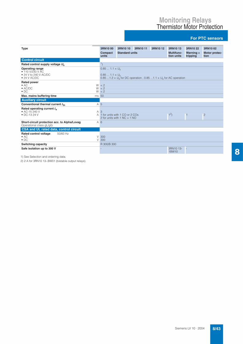
Siemens LV 10 · 2004 8/43
Monitoring RelaysThermistor Motor Protection
For PTC sensors
81) See Selection and ordering data.
2) 2 A for 3RN10 13-.BW01 (bistable output relays).
Type 3RN10 00 3RN10 10 3RN10 11 3RN10 12 3RN10 13 3RN10 22 3RN10 62
Compactunits
Standard units Multifunc-tion units
Warning + tripping
Motor protec-tion
Control circuitRated control supply voltage Us
1)
Operating range• 110 V/230 V AC
0.85 ... 1.1 × Us
• 24 V to 240 V AC/DC 0.85 ... 1.1 × Us• 24 V AC/DC 0.85 ...1.2 × Us for DC operation , 0.85 ...1.1 × Us for AC operation
Rated power• AC W < 2• AC/DC W < 2• DC W < 2
Max. mains buffering time ms 50Auxiliary circuitConventional thermal current Ith A 5
Rated operating current Ie• AC-15 240 V A 3• DC-13 24 V A 1 for units with 1 CO or 2 COs
2 for units with 1 NC + 1 NO12) 1 2
Short-circuit protection acc. to Alpha/LovagOperational class gL/gG
A 6
CSA and UL rated data, control circuitRated control voltage 50/60 Hz• AC V 300• DC V 300
Switching capacity R 300/B 300
Safe isolation up to 300 V - 3RN10 13-1BW10
-

Siemens LV 10 · 20048/44
Monitoring Relays
For PTC sensors
Thermistor Motor Protection
8
Selection and ordering data
Thermistor motor protection relays for PTC thermistors (Type A PTCs) • Monostable version with closed-circuit principle, triggers in the
event of control supply voltage failure
• 3RN10 13-.BW01: bistable version, does not trigger in the event of control supply voltage failure
• All units except for 24 V DC feature electrical isolation
1) The unit can be reset with the RESET button or by disconnecting the con-trol supply voltage.
2) For more information on protection against voltage failure, see Page 8/40.
RESET Contacts Rated control sup-ply voltage Us50/60 Hz
DT Screw connection PS* Weight per PU approx.
DT Spring-loadedterminal
PS* Weight per PU approx.
Order No. Order No.V kg kg
Compact signal evaluation units, width 22.5 mm, 1 LEDTerminal A1 is jumpered with the root of the changeover contactAuto 1 CO 24 AC/DC 3RN10 00-1AB00 1 unit 0.109 A 3RN10 00-2AB00 1 unit 0.099
110 AC 3RN10 00-1AG00 1 unit 0.150 3RN10 00-2AG00 1 unit 0.137230 AC 3RN10 00-1AM00 1 unit 0.149 3RN10 00-2AM00 1 unit 0.137
Standard evaluation units, width 22.5 mm, 2 LEDs
3RN10 12-2CK00
3RN10 13-1BB00
3RN10 13-1BW01
Auto 1 NO + 1 NC 24 AC/DC A 3RN10 10-1CB00 1 unit 0.127 A 3RN10 10-2CB00 1 unit 0.111110 AC 3RN10 10-1CG00 1 unit 0.167 A 3RN10 10-2CG00 1 unit 0.149230 AC 3RN10 10-1CM00 1 unit 0.167 A 3RN10 10-2CM00 1 unit 0.15024 ... 240 AC/DC A 3RN10 10-1CW00 1 unit 0.138 A 3RN10 10-2CW00 1 unit 0.119
2 COs 24 AC/DC A 3RN10 10-1BB00 1 unit 0.153 B 3RN10 10-2BB00 1 unit 0.139110 AC A 3RN10 10-1BG00 1 unit 0.203 B 3RN10 10-2BG00 1 unit 0.139230 AC A 3RN10 10-1BM00 1 unit 0.204 B 3RN10 10-2BM00 1 unit 0.180
2 COs. hard gold-plated
24 AC/DC A 3RN10 10-1GB00 1 unit 0.154 B 3RN10 10-2GB00 1 unit 0.139
Manual/remote1) 1 NO + 1 NC 24 AC/DC 3RN10 11-1CB00 1 unit 0.154 3RN10 11-2CB00 1 unit 0.114110 / 230 AC 3RN10 11-1CK00 1 unit 0.179 3RN10 11-2CK00 1 unit 0.154
Short-circuit detection for sensor circuitManual/remote1) 2 COs 24 AC/DC A 3RN10 11-1BB00 1 unit 0.155 B 3RN10 11-2BB00 1 unit 0.131
110 AC A 3RN10 11-1BG00 1 unit 0.205 C 3RN10 11-2BG00 1 unit 0.182230 AC B 3RN10 11-1BM00 1 unit 0.204 A 3RN10 11-2BM00 1 unit 0.181
2 COs, hard gold-plated
24 AC/DC B 3RN10 11-1GB00 1 unit 0.155 B 3RN10 11-2GB00 1 unit 0.154
Non-volatile2)Manual/auto/remote
1 NO + 1 NC 24 AC/DC 3RN10 12-1CB00 1 unit 0.140 A 3RN10 12-2CB00 1 unit 0.115110 / 230 AC 3RN10 12-1CK00 1 unit 0.180 A 3RN10 12-2CK00 1 unit 0.161
Non-volatile2), short-circuit detection in sensor cir-cuitManual/auto/remote
2 COs 24 AC/DC A 3RN10 12-1BB00 1 unit 0.154 B 3RN10 12-2BB00 1 unit 0.1302 COs 110 AC A 3RN10 12-1BG00 1 unit 0.205 B 3RN10 12-2BG00 1 unit 0.1302 COs 230 AC A 3RN10 12-1BM00 1 unit 0.205 B 3RN10 12-2BM00 1 unit 0.181
2 COs, hard gold-plated
24 AC/DC A 3RN10 12-1GB00 1 unit 0.155 B 3RN10 12-2GB00 1 unit 0.161
Non-volatile2); short-circuit and open-circuit detec-tion and indication in sensor circuit; wide-range volt-age with screw connection with safe isolationManual/auto/remote
2 COs 24 AC/DC 3RN10 13-1BB00 1 unit 0.160 A 3RN10 13-2BB00 1 unit 0.13424 ... 240 AC/DC 3RN10 13-1BW10 1 unit 0.167 3RN10 13-2BW00 1 unit 0.145
2 COs, hard gold-plated
24 ... 240 AC/DC 3RN10 13-1GW10 1 unit 0.168 A 3RN10 13-2GW00 1 unit 0.143
Evaluation units for 2 sensor circuits, warning and switching off, width 22.5 mm, 3 LEDs
Test/RESET button, non-volatile2)Manual/auto/remote
1 NO + 1 CO 24 ... 240 AC/DC 3RN10 22-1DW00 1 unit 0.167 A 3RN10 22-2DW00 1 unit 0.147
Signal evaluation units for 6 sensor circuits, warning and switching off, width 45 mm, 8 LEDs
Test/RESET button, non-volatile2)Manual/auto/remote
1 NO + 1 NC 24 ... 240 AC/DC 3RN10 62-1CW00 1 unit 0.296 A 3RN10 62-2CW00 1 unit 0.246
Bistable evaluation units, width 22.5 mmTest/RESET button, non-volatile2)Short-circuit and open-circuit detection and indica-tion in sensor circuitManual/auto/remote
2 COs 24 ... 240 AC/DC A 3RN10 13-1BW01 1 unit 0.165 A 3RN10 13-2BW01 1 unit 0.139
AccessoriesPush-in lugs for screw mounting2 units required per 3RN1 thermistor motor protection device1 package contains 10 units for 5 devices
3RP19 03 10 units 0.018
* This quantity or a multiple thereof can be ordered.

Siemens LV 10 · 2004 8/45
Monitoring RelaysThermistor Motor Protection
For PTC sensors
8
Circuit diagrams
Connection diagrams
1) For units with combination voltages AC 230 V/110 V (3RN10 11-.CK00 and 3RN10 12-.CK00) the following applies: A1 and A2: 230 V AC, A3 and A2: 110 V AC.
Representation with control voltage applied
Representation with control voltage not applied
Representation with control voltage applied
Representation with control voltage not applied
3RN10 00, 1 CO
3RN10 10, 1 NO + 1 NC 3RN10 10, 2 COs
3RN10 111), 1 NO + 1 NC 3RN10 11, 2 COs
3RN10 121), 1 NO + 1 NC 3RN10 11, 2 COs
3RN10 13-...0 (monostable)
3RN10 13-...1 (bistable)
3RN10 22
3RN10 62
General item codes
A1, A2 , A3
NT/RY1, Y2
⇑
Connections of the con-trol voltageAmplifierTEST/RESET buttonConnections for remote RESET (jumpered = auto-RESET)The double arrow indicates an operating status which deviates from the standard repre-sentation of the contact according to DIN 40900, Part 7 (in this case: position of the contacts when con-trol voltage is applied to terminals A1 and A2)
Item code for 3RN10
H1H2KT1, T2
"READY" LED"TRIPPED" LEDOutput relayConnections of thesensor loop
Item code for 3RN10 22
H1H2H3K1, K21T1 and T22T1 and T2
"READY" LED "TRIPPED" LED "ALARM" LED Output relayConnections of thesensor loop
. Important!
Close unconnected sensor circuits
Item code for 3RN10 62
H1 to H6
H7H8K1T1, 1T2to6T1, 6T2
LED for the tripped sen-sor loop
"READY" LED "TRIPPED" LED Output relayConnections of the first sensor loop Connections of the sixth sensor loop
. Important!
Close unconnected sensor circuits
$
$ $
%
$ $
$ $
%
%
$ $
$
%
$
%
$ $
$ $
%
%
$ $
$
%
$
%
$ $
$ $ %
%
$ $
$
%
$$
%
$ $
$
%
%
%
%
$ $
$
$
$ $
%
%
%
&
$ $
$
% %
%
%
$
$

Siemens LV 10 · 20048/46
Monitoring Relays
General data
Monitoring Relays for Electrical Variables
8
Overview
The solid-state monitoring relays are offered in the field-proven design with different functions. These relays are used to detect wear effects and potential faults at an early stage and to respond to them before more serious secondary damage can occur. With their minimal space requirements, high measuring accuracy and optimized functions for high reliability, they are easy to use.
For example, the monitoring modes "Overcurrent/overvoltage" and "Undercurrent/undervoltage" can be set for the relay for cur-rent and voltage monitoring using a DIP switch. Similarly, the latching/unlatching function as well as various delay times can be set.
Area of application
Depending on the relay type, these relays can be used for mon-itoring electrical and non-electrical variables. They respond, for example, as soon as the set value is reached and drop as soon as the value is below the set value.
According to the relay version, they can be used for device and system protection in AC and DC systems. Combined with circuit-breakers, they can, for example, be used for overload protection of motors in chain conveyors, packaging machines etc.
Technical specifications
Note:
Fuse protection of the measurement circuit is not required for de-vice protection. Conductor protection depends on the conductor cross-section used.1) Short-circuits without any contact welding to EN 60947-5-1.
Type 3UG30/3UG35
Load capacity of the output relay Rated operating current Ie A max. 8AC-15/230 V A 3DC-13/24 V A 1DC-13/48 V A 0.45DC-13/60 V A 0.35DC-13/110 V A 0.2DC-13/230 V A 0.1
Minimum contact load mA 5/17 V for a fault of 1 ppm
Output relayDIAZED fuse protection1)
Operational class gl/Gg A 4
Electrical endurance Operating cycles 1 × 10⁵
Mechanical endurance Operating cycles 2 × 10⁶
Ambient temperature during operation °C – 20 ... + 50during storage °C – 30 ... + 70
Conductor connection solid mm² 2 × (0.5 ... 2.5)finely stranded, with end sleeves mm² 2 × (0.5 ... 1.5)
Degree of protection Terminals: IP20Housing IP40
Can be used in networks 3UG30 13/3UG35 11 AC V 660other 3UG3 AC V 480
Vibration resistance to IEC 60068-2-6 Hz/mm
10 ... 150/0.035

Siemens LV 10 · 2004 8/47
Monitoring RelaysMonitoring Relays for Electrical Variables
General data
8
Circuit diagrams
Voltage monitoring relay, single-phase 3UG35 31, 3UG35 32
Voltage monitoring relay, single-phase 3UG35 34, 3UG35 35
Phase monitoring relay, three-phase 3UG35 11
IN1/IN2/IN3: AC/DC A1/A2: AC/DC
Level monitoring relay 3UG35 01
Current monitoring relay, single-phase 3UG35 21, 3UG35 22
IN1/IN2/IN3: AC/DC
Voltage monitoring relay, three-phase 3UG30 41
Voltage monitoring relay with N, three-phase,3UG30 42
Asymmetry monitoring relay, three-phase 3UG30 12
Underspeed monitoring relay 3UG30 51
Line monitoring relay, three-phase 3UG30 13
Power factor monitoring relay, single- and three-phase, 3UG30 14, three-phase operation, I < 10 Ak
Power factor monitoring relay, single- and three-phase, 3UG30 14, three-phase operation, I > 10 Ak
Power factor monitoring relay, single- and three-phase, 3UG30 14 single-phase operation, 230 Vk
!
!"
#
$%&$
'
!
() ()
()
'
!
() ()
()
*+, +,
-+, +,
./000//0)1(020
'
() ()
()
(3

Siemens LV 10 · 20048/48
Monitoring Relays
General data
Monitoring Relays for Electrical Variables
8
Connection diagram for DC 24 V
Current monitoring relay, single-phase 3UG35 21, 3UG35 22
For current relays with a DC 24 V supply voltage, A2 and M must not be jumpered in the device otherwise the relays will not func-tion. The circuit diagrams below show that loads in DC measur-ing circuits must be upstream from the monitoring relay and that AC loads must only be connected via converters. Otherwise the monitoring relay will be damaged and the short-circuit current can cause damage to the plant.
Configuring note:
For measuring currents of 10 A and side-by-side mounting, the maximum ambient temperature is 40 °C
The internal configuration of the 3UG35 21/22 current monitoring relay for DC 24 V control supply voltage has been changed.In the new internal circuit the control supply voltage and the measuring-circuit voltage should not have the same reference potential.In cases in which the load to be monitored and the monitoring relay are fed by the same power supply, the function of the cur-rent monitoring relay is no longer provided. The devices are, however, not destroyed as a result. Relief is provided in the form of a second power supply that is not directly connected to the control supply voltage.
Please therefore pay attention to the connection information shown in the circuit diagram for the new current monitoring re-lays!
Connection diagram for 24...240 V DC
Insulation resistancefor ungrounded DC voltage networks
Connection diagram for networks up to 400 V AC
Insulation resistancefor ungrounded voltage networks
NS
B0_
0139
6
A1
A2
L+
PE
Y2
11
1412
Y1
Y4
Y3
Test L-
24...240 V AC/DC
R
24...240 V DC
L
L+
L-N
PE
L-
Test L+Reset
L1
L2
L3
3 x 230/400 V AC
A1
A2 B21)
N 230 VN 115 VPE
R
A1
A2 B21)
N 230 VN 115 V
L
PE Y2
Y1
11
1412
NS
B0_
0139
4a
) 3UG3081-1AK20 only1A1-B2/A1-A2 für AC 115 V/230 VA1-A2 für AC/DC 24...240 V
TestReset

Siemens LV 10 · 2004 8/49
Monitoring RelaysMonitoring Relays for Electrical Variables
Phases and voltage:Phase failure and phase sequence monitoring
8
Functions
Depending on version, the 3UG35 11 and 3UG35 13 relays mon-itor the phase sequence and failure of one of the three phases. During operation, no adjustment is required. If the phase se-quence is correct and none of the three phases have failed, the output relay picks up after the delay time T1 has elapsed and the LED is lit. On phase failure, the output relay trips after the delay time T2 has elapsed and the LED is no longer lit.
If a phase sequence fault is detected when the voltage is switched on, the relay will not pick up.
The 3UG35 11 relay does not detect any voltage feedback into the supply
The 3UG35 11 relay is not protected against feedback of voltage into the supply. If there is a risk of feedback from a motor in the case of phase failure or voltage loops through parallel loads, the 3UG35 13 with fixed operating point or 3UG30 13 relays with ad-justable operating point can be used.
3UG35 13 for detection of phase failure
The fixed undervoltage detection ensures that the relay also trips in the case of voltage feedback from the motor. Feedback from the motor or caused by voltage loops will be detected at up to 90 % of the rated voltage.
Technical specifications
Selection and ordering data
Screw connection
Standard rail mounting Width 22.5 mm
Phase monitoring relay, three-phase • Monitoring of phase failure and phase sequence • 1 yellow LED for indicating the relay state • 2 changeover contacts
! " ! # $ % &
' $ % & ( ! ) * $ ! # ) + $
* , * +
' $ % & ( ! ) * $ ! # "
* , * +
Type 3UG35 11 3UG35 13
Rated control supply voltage Us V 3 x 230 ... 400 (phase-to-phase)
see Selection data
Voltage tolerance V 3 × 200 ...460 (corresponds to 0.85 ...1.15 × Us)
0.8 ...1.15 × Us
Power consumption• at 200 V VA 5• at 400 V VA 20• at 460 V VA 25Undervoltage detection fixed % none 90
Frequency of the monitored line Hz 50/60
Delay time• T1 for correct phase sequence ms max.. 200• T2 for phase failure ms approx. 300
Version Measuring range Ue
AC 50/60 Hz
Rated control supply voltage UsAC 50/60 Hz
DT Order No. PS* Weight per PU approx.
V V kg
No tripping following voltage feedback by the consumer loadMeasuring-circuit voltage = control supply voltage
3 × 230 ... 400 phase conductor voltage
3 × 230 ... 400 phase conductor volt-age
3UG35 11-1BQ50 1 unit 0.120
Detection following voltage feedback by the consumer load of up to 90 %Measuring-circuit voltage = control supply voltage
3 × 230 3 × 230 A 3UG35 13-1BL50 1 unit 0.1123 × 400 phase conductor voltage
3 × 400 A 3UG35 13-1BP50 1 unit 0.112
* This quantity or a multiple thereof can be ordered.

Siemens LV 10 · 20048/50
Monitoring Relays
Phases and voltage:Phase asymmetry monitoring
Monitoring Relays for Electrical Variables
8
Functions
The relay monitors voltage imbalances in the three-phase sys-tem. If the phase sequence is correct and the imbalance is less than the set threshold value, the output relay picks up and the yellow LED is lit. The relay trips when one of the following faults occurs:• Incorrect phase sequence on terminals L1-L2-L3• Failure of a phase• System imbalance greater than the set threshold.
A system imbalance means that the voltage of one of the phases rises or falls in relation to the voltage of the other two phases. This is used to detect voltage feedback from a running drive (e.g. on failure of a fuse) of up to 95 % of the rated voltage as a fault.
The time delay T1 is only effective in the case of imbalance faults and when phase L3 fails. Hysteresis prevents the output relay from continuously switching on and off when the system imbal-ance is close to the set value.
The relay does not respond to a symmetrical overvoltage or un-dervoltage.
Technical specifications
Selection and ordering data
Screw connection
For mounting standard rail or screw fixing Width 45 mm
Phase asymmetry monitoring relay, three-phase • phase asymmetry monitoring • phase sequence and phase failure monitoring • 1 yellow LED for indicating the relay state flashes during oper-
ating time T • 1 green LED for indicating applied control supply voltage • 1 changeover contact
-
$ ! + & * * $ ! # ) . % / % $
0 & + ! $ # $ + ) +
$ 1 # $ $ 2 3 4 % 3 . $
! " ! # $ % &
Rated control supply voltage Us V see Selection data (L1/L2 also used to supply units)
Voltage tolerance 0.8 ...1.2 × Us
Maximum power consumption W/VA 4/8
Frequency of the measuring-circuit voltage Hz 50/60 switchable
Max. setting range for asymmetry value % adjustable to 5 to 20 % of the nominal supply voltage
Max. hysteresis % fixed at 10 % of set asymmetry value
Setting accuracy % ± 20 referred to maximum asymmetry value
Repeat accuracy at constant parameters % ± 1
Deviations with temperature fluctuations %/°C ± 0.1
Delay time• T1 when relay drops s adjustable to 0.5 ... 10 ± 60 % or T2 in case of phase failure of L1 or L2• T3 when relay picks up s max. 1• T2 in case of phase failure L1 or L2 ms max. 300
Mains buffering time ms 10
Version Measuring-circuit volt-ageUeAC 50/60 Hz
DT Order No. PS* Weight per PU approx.
V kg
Measuring-circuit voltage = control supply volt-age, asymmetry value and delay time, adjustable
3 × 230 phase-to-phase voltage
3UG30 12-1AL50 1 unit 0.299
3 × 400 phase-to-phase voltage
3UG30 12-1AP50 1 unit 0.305
* This quantity or a multiple thereof can be ordered.

Siemens LV 10 · 2004 8/51
Monitoring RelaysMonitoring Relays for Electrical Variables
Phases and voltage:Line monitoring
8
Functions
The 3UG30 13 relay monitors the phase sequence, failure of a phase and undershoot of the set measuring voltage by 20%. If the phase sequence is correct and the monitored voltage corre-sponds to the value of the set measuring voltage, the output re-lay picks up and the LEDs for the operating voltage display and the relay status are lit.
If a phase fails, the output relay trips (in the case of failure of L3, only after the time T that can be set at the front) and the LED for relay status goes off.
If the monitored voltage falls symmetrically (L1, L2 and L3 simul-taneously) or asymmetrically (only one phase) by more than 20% of the set measuring voltage, the output relays will also trip after the set time T has elapsed and the associated LED goes off.
If the monitored voltage rises again above a hysteresis of be-tween 2% and 10% of the set measuring voltage, the output re-lays pick up again and the LED is lit.
Note:
After failure of a phase on a rotating motor, a feedback voltage of up to 70% of the set rated motor voltage is recognized as a fault.
The setting for the measuring voltage can be increased to in-crease the percentage for the maximum detectable feedback into the supply.
Technical specifications
Selection and ordering data
Screw connection
For mounting onto standard rail or screw fixing Width 45 mm
Line monitoring relay, three-phase • phase failure and phase sequence monitoring• monitoring of the variable measuring-circuit voltage• 1 yellow LED for indicating the relay state • 1 green LED for indicating applied control supply voltage • 2 changeover contacts
-
-
-
3 $ + # ) 3 1 ( . ) # . ) ! / % ! 1 $
! " ! # $ % &
Rated control supply voltage Us V see Selection data (L1/L2 also used to supply units)
Voltage tolerance V see Selection data
Maximum power consumption W/VA 5/8
Frequency of the monitored line Hz 50/60
Measuring-circuit voltage of the monitored line adjustable within the associated measuring range, absolute scale for Ue
Undervoltage detection % – 20 ± 10 of the set measuring-circuit voltage
Hysteresis• with symmetrical undervoltage % fixed, 2...5 of the set measuring-circuit voltage• with asymmetrical undervoltage % fixed, 5...10 of the set measuring-circuit voltage
Delay time T on detection of a line fault s adjustable 0.2 ... 10; ± 50%
Response time on detection of a disturbance ms 400
Availability time after application of Us ms 500
Operating frequency at max. make-break capacity 1/h 360
Mains buffering time ms 10
Version Measuring range UeAC 50/60 Hz
=Rated control supply voltage Us
DT Order No. PS* Weight per PU approx.
V kg
Phase conductor volt-age
Measuring-circuit voltage = control supply voltage,measuring-circuit voltage and delay time adjustable
3 × 180 ... 260 3UG30 13-1BL60 1 unit 0.3173 × 320 ... 460 3UG30 13-1BP60 1 unit 0.3133 × 380 ... 550 3UG30 13-1BR60 1 unit 0.3563 × 460 ... 660 3UG30 13-1BS60 1 unit 0.355
* This quantity or a multiple thereof can be ordered.

Siemens LV 10 · 20048/52
Monitoring Relays
Phases and voltage:Single-phase voltage monitoring
Monitoring Relays for Electrical Variables
8
Functions
The relays monitor single-phase voltages against the set thresh-old. The products differ not only with respect to their measuring ranges and voltage types but also with regard to their functions:• Supplied from an external auxiliary supply
(3UG35 31/3UG35 32)• Internal power supply and no auxiliary supply
(3UG35 34/3UG35 35)• Overshoot/undershoot, latching/unlatching, selectable
(3UG35 31/3UG35 32/3UG35 34)• Window principle with upper and lower threshold (3UG35 35)
The latching/unlatching function can be set for the 3UG35 31, 3UG35 32 and 3UG35 34 relays using a DIP switch on the bot-tom of the device. The 3UG35 34 relay has an internal power supply, i.e. in the following diagram, A1/A2 is replaced by the measuring-circuit voltage.
Advantages of the products that are supplied from an exter-nal supply• Extremely low loading on the measuring signals• Large measuring range is necessary
Advantages of the products that are supplied from an inter-nal supply• No separate supply voltage is necessary• Low wiring overheads
Voltage monitoring without memory (NO MEMORY)
As soon as the measuring-circuit voltage reaches the set thresh-old, the output relay changes its output state as soon as the set time T1 has elapsed. The relay returns to its original state as soon as the measuring-circuit voltage reaches the set hysteresis value.
with memory (MEMORY)
If the set threshold is reached, the output relay changes its state as soon as the set time T1 has elapsed and it remains latched in this position even when the measuring-circuit voltage reaches the set hysteresis value. The relay is reset (RESET) by switching the supply voltage off and on again.
3UG35 35 relay, internal power supply with windows-type technology
The 3UG35 35 relay monitors the applied voltage using the win-dows principle. The upper and lower thresholds are set and monitored. As soon as the monitored voltage leaves the set range, the output relay trips after the set time T1 has elapsed.
Configuring note:
When the upper and lower threshold are too close, the toler-ances of the setting accuracy and of the two hysteresis settings can result in undefined output states.
5
$ 6 # $ + 6 % / % $
0 & + ! $ # $ + ) +
$ + # ) 3 1 ( . ) # . ) ! / % ! 1 $
! " ! # $ % &
7 3 . ! ) 3 8 9
! " ! # $ % &
7 3 . ! ) 3 8 9
:
5
:
:
:
$ 6 # $ + 6 % / % $
0 & + ! $ # $ + ) +
$ + # ) 3 1 ( . ) # . ) !
/ % ! 1 $
! " ! # $ % &
7 3 . ! ) 3 8 9
! " ! # $ % &
7 3 . ! ) 3 8 9
! # 1 $ 8 9 ;
0 & + ! $ # $ + ) +
$ + # ) 3 1 ( . ) # . ) ! / % ! 1 $
" " $ # " $ / % $
< $ # " $ / % $
! " ! # $ % &

Siemens LV 10 · 2004 8/53
Monitoring RelaysMonitoring Relays for Electrical Variables
Phases and voltage:Single-phase voltage monitoring
8
Technical specifications
Monitoring relays with external power supply
1) Observe rated insulation voltage.
Monitoring relays with internal power supply
Type 3UG35 31 3UG35 32
Rated control supply voltage Us V see Selection data (for AC voltages with electrical isolation by means of transformer, 24 V DC without electrical isolation)
Voltage tolerance 0.8 ...1.15 × Us
Maximum power consumption W/VA 4/5
Rated insulation voltage UiPollution degree 2 Overvoltage category III to DIN VDE 0110
AC V 300
Frequency of the measuring-circuit voltage Hz 40 ... 500 and DC
Threshold value Ue % adjustable to 10 ...100 of the selected measuring range
Hysteresis % adjustable from 5 to 50 % of the set threshold value
Setting accuracy % ± 10 referred to upper limit of measuring range
Repeat accuracy at constant parameters % ± 0.1
Delay time T1 after reaching the threshold s adjustable to 0.1 ... 3 ± 10 %
Availability time after application of Us ms max. 500
Mains buffering time ms 10
Measuring range inputs• IN1-M
- sensitivity V 0.2 ... 2 15 ... 150- input resistance kΩ 2 150- overvoltage strength V 4 200
• IN2-M- sensitivity V 1 ... 10 30 ... 300- input resistance kΩ 10 300- overvoltage strength V 20 350
• IN3-M- sensitivity V 6 ... 60 60 ... 6001)- input resistance kΩ 60 600- overvoltage strength V 120 650
Function mode setting• Overvoltage or undervoltage slide switch in lower part of unit• With or without memory slide switch in lower part of unit
Type 3UG35 34 3UG35 35
Rated control supply voltage Us V see Selection data
Voltage tolerance see Selection data, min./max. values
Maximum power consumption W/VA 2/7
Frequency of the measuring-circuit voltage Hz 50/60 and DC
Threshold value Ue absolute scale for Ue absolute scale for Ue min and Ue max
Hysteresis % adjustable from 5 to 20 of the set threshold value
fixed at 5 of the set threshold
Setting accuracy % ± 10 referred to upper limit of measuring range
Repeat accuracy at constant parameters % 0.3
Delay time T1 after reaching the threshold s adjustable to 0.1 ... 3 ± 10 %
Measuring range inputs A1/A2:• IN1-M
Min. sensitivity A see Selection data, measuring range of the corresponding versionOvervoltage strength V see Selection data, upper limit of rated control supply voltage
Function mode setting• Overvoltage or undervoltage slide switch fixed: overvoltage and undervolt-
age• With or without memory slide switch fixed: without memory

Siemens LV 10 · 20048/54
Monitoring Relays
Phases and voltage:Single-phase voltage monitoring
Monitoring Relays for Electrical Variables
8
Selection and ordering data
Monitoring relays with external power supply
Screw connectionMounting onto standard railWidth 22.5 mm
Voltage monitoring relay, single-phase• Overvoltage and/or undervoltage monitoring for DC and AC
voltages• 1 yellow LED for indicating the relay state• 1 green LED for indicating applied control supply voltage• 1 changeover contact
1) The rated control supply voltage and the measuring circuit are not electri-cally isolated.
Monitoring relays with internal power supply
Screw connectionFor mounting onto standard railWidth 22.5 mm
Voltage monitoring relay, single-phase Absolute scale • Overvoltage and/or undervoltage mode, depending upon ver-
sion• 3UG35 34:
1 yellow LED for indicating the relay state and 1 green LED for indicating applied control supply voltage
• 3UG35 35: 1 yellow LED for indicating the relay state and 1 yellow LED each for Umin and Umax;Umin = flashing, Umax = off
• 1 changeover contact
Version Measuring range UeAC/DC
Rated control supply voltage Us DT Order No. PS* Weight per PU approx.
AC 50/60 Hz DC
V V V kg
electrical isola-tionAC: yes DC: no adjustablethreshold and hysteresis
0.2 ... 60 (3 ranges) 24 A 3UG35 31-1AC20 1 unit 0.155120 D 3UG35 31-1AG20 1 unit 0.155230 3UG35 31-1AL20 1 unit 0.157
241) 3UG35 31-1AC40 1 unit 0.115
15 ... 600 (3 ranges) 24 3UG35 32-1AC20 1 unit 0.161120 3UG35 32-1AG20 1 unit 0.161230 3UG35 32-1AL20 1 unit 0.159
241) 3UG35 32-1AC40 1 unit 0.118
Version Measuring range UeAC/DC
Rated control supply voltageUs
DT Order No. PS* Weight per PU approx.
AC 50/60 Hz DC
V V V kg
3UG35 34
Measuring-circuit volt-age = control supply voltage no adjustable threshold and hysteresis
20 ... 80 15 ... 150 15 ... 150 3UG35 34-1AC50 1 unit 0.10765 ... 260 50 ... 275 50 ... 275 3UG35 34-1AM50 1 unit 0.107
3UG35 35
Measuring-circuit volt-age = control supply voltage upper and lower threshold value can be adjusted separately
20 ... 80 15 ... 150 15 ... 150 3UG35 35-1AC50 1 unit 0.10865 ... 260 50 ... 275 50 ... 275 3UG35 35-1AM50 1 unit 0.107
* This quantity or a multiple thereof can be ordered.

Siemens LV 10 · 2004 8/55
Monitoring RelaysMonitoring Relays for Electrical Variables
Phases and voltage:Three-phase voltage monitoring
8
Functions
The output relay has tripped, provided that the values of the three phase conductor voltages in the case of 3UG30 41 or the three star voltages of the phases with reference to the neutral conductor in the case of 3UG30 42 lie between the lower and upper threshold. These are set separately on the front using two potentiometers.
When the value of one voltage lies outside this range, the corre-sponding output relay will trip after elapse of a delay time T1 or T2 that can be set separately on the front.
A fixed hysteresis of 3% prevents the output relay from continu-ously switching on and off when the measuring-circuit voltage is close to the threshold.
The monitoring relay detects voltage feedback from running drives up to the level of the set minimum threshold Umin.
The phase sequence is not monitored. The 3UG30 42 relay also responds to failure of the neutral conductor.
Technical specifications
Selection and ordering data
Screw connection
For mounting onto standard rail and screw fixing Width 45 mm
Three-phase voltage monitoring relay with/without N conductor • Upper and lower threshold value can be adjusted separately • 1 changeover contact for undervoltage and 1 changeover con-
tact for overvoltage • 1 yellow LED each for indicating undervoltage or overvoltage • 1 green LED for indicating applied control supply voltage
:
5
5
5
* ,
* ) 3
* ) 3
* ,
6 # $ + 6 % / % $
0 & + ! $ # $ + ) +
6 # $ + 6 % / % $
! " ! # $ % & =
> ! $ # * ) 3 % ? ? @
! " ! # $ % & A
> ! $ # * ) 3 % ? ? @
Type 3UG30 41 3UG30 42
Rated control supply voltage Us V 400 phase conductor voltage(L1/L2 also used to supply units)
400 phase conductor voltage/230 star voltage (L1/L2 also used to supply units)
Voltage tolerance 0.8 ...1.2 × Us
Maximum power consumption W/VA 4/8
Frequency of the measuring-circuit voltage Hz 50/60
Threshold value Un min. 0.85 ... 0.98 × Un (340 ... 392 V phase/phase)max. 1.02 ... 1.15 × Un (408 ... 460 V phase/phase)
Monitoring undervoltage and overvoltage failure L1/L2/L3
undervoltage and overvoltage failure L1/L2/L3/N
Hysteresis fixed % up to 3 of the set threshold
Setting accuracy % ± 10
Delay time T1/T2 after reaching the threshold s adjustable to 0.1 ... 10; ± 50%
Response time on occurrence of a fault ms 500
Availability time after application of Us s 3
Mains buffering time ms 10
Version Measuring-circuit voltage UeAC 50/60 Hz
Rated control supply voltage Us
DT Order No. PS* Weight per PU approx.
V V kg
3UG30 41
3UG30 41 Measuring-circuit voltage = con-trol supply voltage; upper and lower threshold can be adjusted individually, hysteresis fixed
400 (phase to phase) 400 3UG30 41-1BP50 1 unit 0.313
3UG30 42 Measuring-circuit voltage = con-trol supply voltage with monitor-ing N conductor, upper and lower threshold adjustment can be adjusted individually, hystere-sis fixed
400 (phase to phase) 230 (phase to N conductor)
400230
3UG30 42-1BP50 1 unit 0.315
* This quantity or a multiple thereof can be ordered.

Siemens LV 10 · 20048/56
Monitoring Relays
Current:Single-phase current monitoring
Monitoring Relay for Electrical Variables
8
Functions
The relays monitor single-phase currents against the set thresh-old. The products differ with regard to their measuring ranges and voltage types.
If the load on a motor changes, the motor current also changes. This effect can be used to monitor loading on a motor by means of the current. Thus wear effects on tools, blocked loads, etc. are detected. It is also possible to check the functionality of load in this way. If current is flowing, the load is functioning. The relay can also be used as a trigger for analog signals.
The latching/non-latching function can be set for the relay using a DIP switch underneath the relay. It is also possible to set two delay times.
Current monitoring without memory (NO MEMORY)
As soon as the value of the monitored AC or DC current reaches the threshold set on the front, the output relay trips after the set time T1 has elapsed. The relay picks up immediately again when the current reaches the hysteresis value again.
Current monitoring with memory (MEMORY)
If the set threshold is reached, the output relay trips as soon as the set time T1 has elapsed and it remains stored in this position even when the measured current reaches the set hysteresis value. The relay is reset by switching the supply voltage off and on again.
ON delay T1 and T2:
Due to the ON delay T2, current peaks (OVER function) or cur-rent falls (UNDER function), that can occur when switching on, do not cause a change in relay status, e.g. for suppression of the inrush current on motor starting. The delay time T1 prevents the relay from continuously switching on and off when the measured current is close to the set threshold.
Note:Please see the connection diagrams and notes under General data, circuit diagrams.
:
5
$ 6 # $ + 6 % / % $
0 & + ! $ # $ + ) +
3 ) ! # $ * $ + # $
. # # $ 3 !
! " ! # $ % &
7 3 . ! ) 3 8 9
! " ! # $ % &
7 3 . ! ) 3 8 9
:
5
:
:
:
$ 6 # $ + 6 % / % $
0 & + ! $ # $ + ) +
3 ) ! # $ * $ + # $
. # # $ 3 !
! " ! # $ % &
7 3 . ! ) 3 8 9
! " ! # $ % &
7 3 . ! ) 3 8 9
! # 1 $

Siemens LV 10 · 2004 8/57
Monitoring RelaysMonitoring Relay for Electrical Variables
Current:Single-phase current monitoring
8
Technical specifications
1) With sinusoidal currents. Measuring principle: arithmetic mean-value gen-eration.
2) For continuous currents of 10 A and devices mounted side by side, the ambient temperature must not exceed +40 °C.
Selection and ordering data
Screw-type connection
For mounting onto standard rail or screw fixing Width 22.5 mm
Current monitoring relay, single-phase • Overvoltage and undervoltage monitoring of DC and AC volt-
ages• 1 yellow LED for indicating the relay state • 1 green LED for indicating applied control supply voltage • 1 changeover contact
1) The rated control supply voltage and the measuring circuit are not electri-cally isolated, see also Page 8/46.
Type 3UG35 21 3UG35 22
Rated control supply voltage Us V see Selection data (for AC voltages with electrical isolation by means of transformer, 24 V DC without electrical isolation)
Voltage tolerance 0.8 ...1.15 × Us
Maximum power consumption W/VA 4/5
Frequency of the measured current Hz 40 ... 500 and DC
Threshold Ie % adjustable to 10 ...100 of the selected effective range
Hysteresis % adjustable from 5 to 50 of the set threshold value
Setting accuracy1) % ± 10 referred to upper limit of effective range
Repeat accuracy at constant parameters % ± 0.1
Deviations at voltage fluctuations % ≤ 0.5with temperature fluctuations %/°C ± 0.05
Delay time T2, ON-delay s 1 ... 20 ± 10%T1 after reaching the threshold s 0.1 ... 3 ± 10%
Effective range inputs• IN1-M
- sensitivity A 0.002 ... 0.02 0.1 ... 1- input resistance Ω 5 0.1- overvoltage strength, continuous A 0.04 2- overvoltage strength < 1 s A 1 17
• IN2-M- sensitivity A 0.01 ... 0.1 0.5 ... 5- input resistance Ω 1 0.02- overvoltage strength, continuous A 0.2 10- overvoltage strength < 1 s A 5 20
• IN3-M- sensitivity A 0.05 ... 0.5 1 ... 102)- input resistance Ω 0.2 0.01- overvoltage strength, continuous A 1 13- overvoltage strength < 1 s A 8 50
Max. voltage in monitoring circuit and permissible potential difference
AC V 480DC V 300
Function mode setting• overcurrent and undercurrent slide switch in lower part of unit• with or without memory slide switch in lower part of unit
Version Effective range UeAC/DC
Rated control supply volt-age Us
DT Order No. PS* Weight per PU approx.AC 50/60 Hz DC
A V kg
electrical isolationAC: yes DC: no adjustable threshold and hysteresis
0.002 ... 0.5 (3 ranges) 24 3UG35 21-1AC20 1 unit 0.273120 A 3UG35 21-1AG20 1 unit 0.157230 3UG35 21-1AL20 1 unit 0.157
241) 3UG35 21-1AC40 1 unit 0.118
0.1 ... 10 (3 ranges) 24 3UG35 22-1AC20 1 unit 0.158120 3UG35 22-1AG20 1 unit 0.156230 3UG35 22-1AL20 1 unit 0.158
241) 3UG35 22-1AC40 1 unit 0.117
* This quantity or a multiple thereof can be ordered.

Siemens LV 10 · 20048/58
Monitoring Relays
Power factor monitoring(motor load monitoring)
Monitoring Relay for Electrical Variables
8
Functions
The 3UG30 14 monitoring relay is used for monitoring the load of motors by measuring the phase angle between voltage and cur-rent, i.e. the power factor. The output relays respond as long as the power factor lies between the upper and lower thresh-olds.These are set separately on the front using two potentio-meters.
When the value of the power factor lies outside this range, the corresponding output relay will drop after a delay time T1 that can be set on the front has elapsed. A fixed hysteresis prevents the output relay from continuously switching on and off when the measured value is close to the threshold. The ON delay T2 can be used to suppress the effects of motor start-up.
Important!
It is important to ensure that the phases are connected in the correct sequence L1-L2-L3, otherwise the power factor will be evaluated incorrectly.
Note:
Power factor monitoring relays are connected in series after the motor contactor to ensure that the delay time for bridging start-up elapses after switch-on. For this reason, the output relay must not be connected in series with the supply voltage of the motor contactor, otherwise it would not be possible to switch on the load feeder.
Technical specifications
Note: currents > 10 A only with current converter.
Selection and ordering data
Screw connection
For mounting onto standard rail and screw fixing Assembly width 45 mm
Relay for power factor monitoring, single and three-phase • monitoring of the power factor for undershoot/overshoot for
motor underload and overload • upper and lower threshold value can be adjusted separately • 1 changeover contact each for undershoot/overshoot • 1 yellow LED each for indicating of undershoot/overshoot• 1 green LED for indicating the applied control supply voltage
flashes with 1 Hz, during the operating time T1 flashes with 2 Hz, if p.f.min ≥ p.f.max
. +
* ,
* ) 3
* ,
* ) 3
6 # $ + 6 % / % $
0 & + ! $ # $ + ) +
6 # $ + 6 % / % $
! " ! # $ % & . + A . +
> ! $ # * ) 3 % + ? ? @
! " ! # $ % & . + = . +
> ! $ # * ) 3 % + ? ? @
Rated control supply voltage Us V see Selection data (L1/L2 also used to supply units)
Voltage tolerance V 0.85 ...1.15 × Us
Maximum power consumption VA 3
Frequency of the monitored line Hz 50 ... 60
Effective range of power factor 0.1 ... 0.99 for lower and upper threshold
Hysteresis fixed % 10 for p.f. ≤ 0.410 ... 30 for p.f. < 0.4
Setting accuracy % ± 10 referred to upper limit of effective range
Repeat accuracy at constant parameters % ± 0.8
Deviations for temperature deviations % ± 0.05/ K
Delay time s 0.5 ... 20 ; ± 20%• T2, ON-delay s 0.3 ... 3 ; ± 20%• T1 after reaching the threshold
Input circuit• Current range A 0.5 ... 10• Peak current (< 1 s) A 50• Input resistance L1/L2/L3 kΩ 2• Input resistance current, IN1 Ω 0.02
Version Measuring range Ue
Rated control supply voltage Us
DT Order No. PS* Weight per PU approx. Phase conductor volt-
ageAC 50/60 Hz
p.f. V kg
3UG30 14
Measured voltage = control supply voltage
0.1 ... 0,99 3 × 230 B 3UG30 14-1BL60 1 unit 0.3113 × 400 3UG30 14-1BP60 1 unit 0.3083 × 480 B 3UG30 14-1BR60 1 unit 0.3553 × 575 B 3UG30 14-1BS60 1 unit 0.350
* This quantity or a multiple thereof can be ordered.
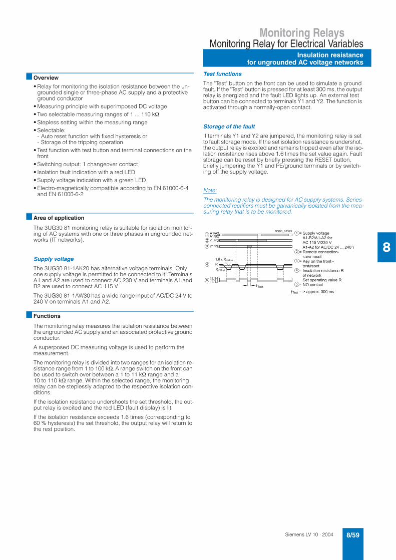
Siemens LV 10 · 2004 8/59
Monitoring RelaysMonitoring Relay for Electrical Variables
Insulation resistancefor ungrounded AC voltage networks
8
Overview
• Relay for monitoring the isolation resistance between the un-grounded single or three-phase AC supply and a protective ground conductor
• Measuring principle with superimposed DC voltage• Two selectable measuring ranges of 1 ... 110 kΩ• Stepless setting within the measuring range• Selectable:
- Auto reset function with fixed hysteresis or- Storage of the tripping operation
• Test function with test button and terminal connections on the front
• Switching output: 1 changeover contact• Isolation fault indication with a red LED• Supply voltage indication with a green LED• Electro-magnetically compatible according to EN 61000-6-4
and EN 61000-6-2
Area of application
The 3UG30 81 monitoring relay is suitable for isolation monitor-ing of AC systems with one or three phases in ungrounded net-works (IT networks).
Supply voltage
The 3UG30 81-1AK20 has alternative voltage terminals. Only one supply voltage is permitted to be connected to it! Terminals A1 and A2 are used to connect AC 230 V and terminals A1 and B2 are used to connect AC 115 V.
The 3UG30 81-1AW30 has a wide-range input of AC/DC 24 V to 240 V on terminals A1 and A2.
Functions
The monitoring relay measures the isolation resistance between the ungrounded AC supply and an associated protective ground conductor.
A superposed DC measuring voltage is used to perform the measurement.
The monitoring relay is divided into two ranges for an isolation re-sistance range from 1 to 100 kΩ. A range switch on the front can be used to switch over between a 1 to 11 kΩ range and a 10 to 110 kΩ range. Within the selected range, the monitoring relay can be steplessly adapted to the respective isolation con-ditions.
If the isolation resistance undershoots the set threshold, the out-put relay is excited and the red LED (fault display) is lit.
If the isolation resistance exceeds 1.6 times (corresponding to 60 % hysteresis) the set threshold, the output relay will return to the rest position.
Test functions
The "Test" button on the front can be used to simulate a ground fault. If the "Test" button is pressed for at least 300 ms, the output relay is energized and the fault LED lights up. An external test button can be connected to terminals Y1 and Y2. The function is activated through a normally-open contact.
Storage of the fault
If terminals Y1 and Y2 are jumpered, the monitoring relay is set to fault storage mode. If the set isolation resistance is undershot, the output relay is excited and remains tripped even after the iso-lation resistance rises above 1.6 times the set value again. Fault storage can be reset by briefly pressing the RESET button, briefly jumpering the Y1 and PE/ground terminals or by switch-ing off the supply voltage.
Note:
The monitoring relay is designed for AC supply systems. Series-connected rectifiers must be galvanically isolated from the mea-suring relay that is to be monitored.
5
5
; 5 ;
; 5 B 8
5
5
9
/ % $
9/ % $
$ + !
$ + !
C A " " # , * +
C " " % & / % ! 1 $
( 5 ( 2 #
5
( 2 # 5
C 9 $ * ! $ . 3 3 $ . ! ) 3 (
+ / $ ( # $ + $ !
C D $ & 3 ! 6 $ 2 # 3 ! (
! $ + ! 5 # $ + $ !
C 3 + % ! ) 3 # $ + ) + ! 3 . $ 9
2 3 $ ! < #
$ ! " $ # ! ) 3 1 / % $ 9
C . 3 ! . !
: , 9

Siemens LV 10 · 20048/60
Monitoring Relays
Insulation resistancefor ungrounded AC voltage networks
Monitoring Relay for Electrical Variables
8
Technical specifications
Selection and ordering data
3UG30 81Control circuitOperating range of the control supply voltage – 15 % ... + 10 %
Rated power AC/DC 24 ... 240 V VA/W 8/2
AC 110/130 V VA 3
AC 220 ... 240 V VA 3
Frequency of the rated control supply voltage Hz 50 ... 60Measurement circuit L/PE/ground• Response value kΩ 1 ... 110 • Minimum internal resistance for AC kΩ 100
• Minimum internal resistance for DC kΩ 100
• DC measurement voltage V DC30
• Insulation voltage V AC 415
• Reset/test function terminals Y1-Y2
• Maximum cable length m 10
• ON-delay s 1
Output relay 1 changeover contact, open-circuit principle
General data Rated insulation voltage Ui between supply, measurement, and
output circuitV 400 acc. to IEC 60947-1
Overvoltage category acc. to IEC 60664 III
Pollution degree acc. to IEC 60664 3
Rated impulse withstand voltage Uimp
acc. to VDE 0435, Part 303 kV 4
Degree of protection acc. to EN 60529 IP50 enclosure, IP20 terminals
Shock resistance acc. to IEC 60068-2-27 g/ms 10
Vibration resistance acc. to IEC 60068-2-6 Hz/mm 10–55/0.35
Permissible ambient temperature• during operation °C – 25 ... 65• during storage °C – 40 ... 85
Permissible mounting position any
Conductor cross-section solid mm2 2 × 0.75 ... 2.5
finely stranded with end sleeve mm2 2 × 0.75 ... 2.5
Effective range Ue Rated control supply voltage Us DT Order No. PS* Weight per PU approx.
kΩ V kgIsolation monitors for ungrounded AC networks
10 ... 110 AC 115/ 230 A 3UG30 81-1AK20 1 unit 0.32710 ... 110 AC/DC 24 ... 240 A 3UG30 81-1AW30 1 unit 0.242
Accessoriessealable, transparent cover A 3UG32 08-1A 1 unit 0.010
* This quantity or a multiple thereof can be ordered.

Siemens LV 10 · 2004 8/61
Monitoring RelaysMonitoring Relay for Electrical Variables
Insulation resistancefor ungrounded DC voltage networks
8
Overview
• Relay for monitoring the isolation resistance between un-grounded purely DC networks and a protective-ground con-ductor
• Measuring principle for differential current measurement• Response threshold can be set continuously from 10 to 110 kΩ• Selectable
- Auto reset function with hysteresis or - Storage of the tripping operation
• Front selector switch for open-circuit and closed-circuit princi-ple for the output relay
• Test function with test buttons on the front for L+ and L-and over terminal connections
• Switching output: 1 changeover contact• Isolation fault indicator for L+ and L- through two red LEDs• Supply voltage indication with a green LED • Electro-magnetically compatible according to EN 61000-6-4
and EN 61000-6-2
Area of application
The 3UG30 82 monitoring relay has been designed for isolation monitoring in ungrounded, purely DC networks with or without fil-tering.It is mainly used to monitor ungrounded DC voltage networks as well as to monitor battery-powered systems.
Supply voltage
Due to the electrical isolation of the supply voltage and the mea-surement circuit, the relay can be used for DC networks in which the auxiliary voltage is either supplied externally or where the network to be monitored also serves as the power supply.
Note:
If the monitoring relay is supplied with an AC 230 V voltage, for example, the terminals A1 and L+ as well as A2 and L– must not be connected with each other!
Functions
The monitoring relay measures the insulation voltage between the positive and negative supply voltage in an ungrounded DC voltage network and a corresponding protective conductor.
The measurement is based on the DC residual current measure-ment principle.The response value can be adjusted steplessly in the range from 10...110 kΩ and thus can be adapted to the corresponding con-ditions. If the insulation resistance falls below the set response value, the output relay triggers (depending on the setting of the open/closed-circuit principle selector switch) and a fault LED lights up.
A ground fault is evaluated separately for L+ and L- and indi-cated by means of a corresponding LED.
Note:
Due to the measurement principle, a symmetrical ground fault on terminals L+ and L- cannot be evaluated.
Test function
A ground fault can be simulated using the Test L+ and Test L- buttons on the front. If the test button is pressed for at least 1 s, the status of the output relay changes and the corresponding fault LED lights up.
An external test button can be connected to terminals Y1-Y3 for L+ and terminals Y4-Y3 for L-. The function is triggered by means of a NO contact.
Storage of the fault
If terminals Y1 and Y2 are linked, the monitoring relay is set to fault storage mode.
If the insulation resistance falls below the set value, the output re-lay triggers (depending on the setting of the open/closed circuit selector switch), and stays in this state even if the insulation re-sistance rises again above the hysteresis value (typical: 2 times the set value). This fault storage can be deleted by pressing and releasing the L+ RESET button, opening the Y2-Y3 connection or by switching off the supply voltage.
Open/closed-circuit principle selector switch
The function principle of the output relay can be adjusted by means of a selector switch on the front panel.
If the relay is to respond in the event of a fault (contact symbol open), the open-circuit principle must be selected. If the relay however is to trigger in the event of a fault (contact symbol closed), the closed-circuit principle must be selected.
Note:
The position of the selector switch has no effect upon the fault LEDs. The LEDs always light up if the insulation resistance on L+ or L– falls below the set value.
5
; 5 ;
5
5
9
9 / % $
; 5 ;
; 5 ;
5 B 8
( 5 B 8
:
$ + !
A +
:
9
$ + !
0 & + ! ,
90 & + !
" $ 3 (
. ) # . ) ! 5
. % + $ (
. ) # . ) !
" # ) 3 . ) " % $
C " " # , +
C ! & " ) . % % & , 9
C " " % & / % ! 1 $
C ! ! 3 3 2 # 3 ! (
9 $ + $ ! 3 ( 5
$ + !
C ! ! 3 3 2 # 3 ! ( $ + ! (
$ + ! # $ * ! $ . 3 3 $ . ! ) 3 (
$ + ! (
C $ + ! # $ * ! $ . 3 3 $ . ! ) 3 (
$ + !
C $ + ! # $ * ! $ . 3 3 $ . ! ) 3 (
! # $ ? # $ + $ !
C 3 + % ! ) 3 # $ + ) + ! 3 . $ 9
2 + " " % &
+ $ ! # $ + " 3 + $ / % $ 9
C < ) ! . 6 3 2 # 3 !
" $ 3 ( . ) # . ) ! 5
. % + $ ( . ) # . ) ! " # ) 3 . ) " % $
C . 3 ! . !

Siemens LV 10 · 20048/62
Monitoring Relays
Insulation resistancefor ungrounded DC voltage networks
Monitoring Relay for Electrical Variables
8
Technical specifications
Selection and ordering data
3UG30 82Control circuitOperating range of the control supply voltage – 15 % ... + 10 %
Rated power AC/DC 24 ... 240 V V VA/W 8/2
Frequency of the rated control supply voltage Hz 50 ... 60Measurement circuit • response value kΩ 10 ... 110
• minimum internal resistance for DC kΩ 57
• measurement DC voltage V 24 ... 240
• max. DC insulation voltage (L+/PE/ground, L-/PE/ground) DC V 300
• reset/test function terminals Y1/Y3, Y4/Y3
• maximum cable length m 10
• ON-delay s 1
Output relay 1 changeover contact, open-circuit or closed-circuit principleGeneral data Rated insulation voltage Ui between supply, measurement, and
output circuitV 400
Overvoltage category acc. to IEC 60664 III
Pollution degree acc. to IEC 60664 3
Rated impulse withstand voltage Uimp
acc. to VDE 0435, Part 303 V 4000
Degree of protection acc. to EN 60529 IP50 enclosure, IP20 terminals
Shock resistance acc. to IEC 60068-2-27 g/ms 10
Vibration resistance acc. to IEC 60068-2-6 Hz/mm
10-55/0.35
Permissible ambient temperature• during operation °C – 25 ... + 65• during storage °C – 40 ... + 85
Permissible mounting position any
Conductor cross-section solid mm2 2 × 0.75 ... 2.5
finely stranded with end sleeve mm2 2 × 0.75 ... 2.5
Effective range Ue Rated control supply voltageUs
DT Order No. PS* Weight per PU approx.
kΩ V kgIsolation monitors for ungrounded DC networks
10 ... 110 AC/DC 24 ... 240 V A 3UG30 82-1AW30 1 unit 0.241
Accessoriessealable, transparent cover A 3UG32 08-1A 1 unit 0.010
* This quantity or a multiple thereof can be ordered.

Siemens LV 10 · 2004 8/63
Monitoring RelaysOther Monitoring Relays
General data
8
Overview
Electronic monitoring relays are offered in the well-proven de-sign with different functions. These relays are used to detect wear effects and potential faults at an early stage and to respond to them before more serious secondary damage can occur. With their minimal space requirements, high measuring accuracy and optimized functions for high reliability, they are easy to use.
Area of application
Relays for level control are used for single-point and two-point level control. With a resistance measurement in the fluid, the lim-its determined by the probe are monitored and the output relay is switched. A range of probes that have been optimized for tank level monitoring are available as accessories.
The relay for speed falls below monitoring is particularly suited to checking belt slip or tears. In addition, any continuous pulse signal can be monitored, e.g. for checking smooth running of a belt, monitoring cycle times or as a watchdog for a control.
Technical data
Note:
Fuse protection of the measurement circuit is not required to pro-tect the device. Conductor protection depends on the conductor cross-section used. 1) Short-circuits without contact welding to EN 60947-5-1.
Type 3UG30/3UG35
Load capacity of the output relay rated operating current Ie A max. 8AC-15/230 V A 3DC-13/24 V A 1DC-13/48 V A 0.45DC-13/60 V A 0.35DC-13/110 V A 0.2DC-13/230 V A 0.1
Minimum contact load mA 5/17 V for a fault of 1 ppm
Output relay, DIAZED fuse1) Operational class gl/Gg A 4
Electrical endurance Operating cycles 1 × 10⁵
Mechanical endurance Operating cycles 2 × 10⁶
Ambient temperature during operation °C – 20 ... + 50during storage °C – 30 ... + 70
Conductor connection solid mm2 2 × (0.5 ... 2.5)finely stranded, with end sleeve
mm2 2 × (0.5 ... 1.5)
Degree of protection Terminals IP20Enclosure IP40
Can be used in networks 3UG30 13/3UG35 11 AC V 660other 3UG3 AC V 480
Vibration resistance acc. to IEC 60068-2-6 Hz/mm 10 ... 55/0.35

Siemens LV 10 · 20048/64
Monitoring Relays
Fill level
Other Monitoring Relays
8
Functions
The principle of operation is based on measuring the electrical resistance of the liquid between two immersion sensors and a reference terminal. If the measured value is lower than the sen-sitivity set at the front, the output relay changes its switching state. In order to exclude electrolytic phenomena in the liquid, the sensors are supplied with alternating current.
Two-level control: the output relay changes its switching state as soon as the liquid level reaches the maximum sensor, while the minimum sensor is submerged. The relay returns to its original switching state as soon as the minimum sensor no longer has contact with the liquid.
For safe resetting, the supply voltage must be interrupted for at least 0.5 s (T3).
The delay times T1 and T2 of the output relay have not been in-cluded in the diagram in order to enhance clarity.
Note:
It is also possible to connect other resistance sensors to the Min and Max terminals in the range 5 ... 100 kΩ e.g. photoresistors, temperature sensors, encoders based on resistance etc.The monitoring relay can therefore also be used for other appli-cations apart from monitoring the levels of conductive liquids.
Technical specifications
1) The sensor cable need not necessarily be shielded, but it is not recom-mended to lay this cable parallel to the power supply lines. It is also possi-ble to use a shielded cable, whereby the shield has to be connected to the M terminal.
Selection and ordering data
Screw connection
Standard rail mounting Width 22.5 mm
Level monitoring relay for conductive liquids• inlet or outlet monitoring adjustable• sensitivity adjustment by potentiometer• 1 yellow LED for indicating the relay state• 1 green LED for indicating applied control supply voltage• 1 changeover contact
: 5
@ $ ! $ # * ) 3 $ 4 & ! 6 $ # # 3 1 $ * $ 3 !
2 ! 6 $ " # 4 $ + ) 3 ! 6 $ * 3 ) ! # $ % ) E )
, ) * * % $ / $ % @
) 3 ) * * % $ / $ % @
3 ) ! # $ % $ / $ %
! " ! # $ % &
7 3 . ! ) 3 8 9
! " ! # $ % &
7 3 . ! ) 3 8 9
Rated control supply voltage Us V see Selection data (electrical isolation by means of a transformer)
Voltage tolerance 0.85 ... 1.1 × Us
Maximum power consumption W/VA 3/6
Function Inlet or outlet monitoring UNDER/OVER slide switch at the front
Sensitivity adjustable kΩ 5 ... 100
Setting accuracy at maximum sensitivity % ± 30
Repeat accuracy at constant parameters % ± 1Sensor length max. m 100
Electrode voltage max. V 24 (50/60 Hz)
Electrode current max. mA 1 (50/60 Hz)
Conductor capacity of the sensor cable1) nF 10
Delay time • T1 at Max/M terminal ms typically 500 (ON-delay with OVER, OFF-delay with UNDER)• T2 at MIN/M terminal ms typically 300 (OFF-delay with OVER, ON-delay with UNDER)
Mains buffering time ms 300
Design Sensitivity Rated control supply voltage Us
DT Order No. PS* Weight per PU approx.AC 50/60 Hz
kΩ V kg
Inlet or outlet monitoring (UNDER/OVER function) adjustable
5 ... 100 24 3UG35 01-1AC20 1 unit 0.143120 3UG35 01-1AG20 1 unit 0.142230 3UG35 01-1AL20 1 unit 0.144
* This quantity or a multiple thereof can be ordered.

Siemens LV 10 · 2004 8/65
Monitoring RelaysOther Monitoring Relays
Fill level
8
Accessories
Sensors for level monitoring
Version Assignment Application DT Order No. PS* Weight per PU approx.
Cable Electrode
kg
Three-pole wire elec-trode, 500 mm long, with Teflon insulation (PTFE), screw-in gland width A/F 22,3/8 inch thread, PVC connecting cable, 3 × 0.5 mm2, 2 m long, max. operating temper-ature 90 °C, max. oper-ating pressure 10 bar
brown center electrode
The electrodes can be cut or bent to the required length before or after installation. The Teflon insulation must be removed over a length of approx. 5 mm. Application: for 2-point liquid level con-trol in an insulating tank. One electrode each for the min. and max. value and a common reference elec-trode.
3UG32 07-3A 1 unit 0.254
whitegreen
not assign-able
Two-pole wire electrode, 500 mm long, with Teflon insulation (PTFE), screw-in gland width A/F 22 mm,3/8 inch thread, PVC connecting cable, 3 × 0.5 mm2, 2 m long, max. operating temper-ature 90 °C, max. oper-ating pressure 10 bar
brown white
not assign-able
For installation, see 3UG32 07-3A
Application: for alarm indi-cation in the event of over-flow or low level and for 2-step liquid-level control, when the conductive tank is used as the reference electrode.
3UG32 07-2A 1 unit 0.230
Two-pole bow electrode, 500 mm long, with Teflon insulation (PTFE), screw-in gland width A/F 22 mm,3/8 inch thread, PVC connecting cable, 3 × 0.5 mm2, 2 m long, max. operating temper-ature 90 °C, max. oper-ating pressure 10 bar
brown gland Thanks to the small space requirements due to lateral fitting, ideal for use in small containers and pipes, as a leak monitor and level monitor or for warning of water entering an enclo-sure.
3UG32 07-2B 1 unit 0.128
whitegreen
not assign-able
Single-pole bow elec-trode for lateral fitting, screw-in gland width A/F 22, 3/8 inch thread, PVC connecting lead,3 × 0.5 mm2, 2 m long, max. operating temper-ature 90 °C, max. oper-ating pressure 10 bar
brown gland As a max. value electrode for lateral fitting or for alarm indication in conduc-tive tanks or pipes.
3UG32 07-1B 1 unit 0.122
white electrode
Single-pole bow elec-trode for lateral fitting, 500 mm long, with Teflon insulation (PTFE), screw-in gland width A/F 22, 3/8 inch thread, PVC connecting cable, 3 × 0.5 mm2, 2 m long, max. operating temper-ature 90 °C, max. oper-ating pressure 10 bar
brown gland For high flow velocities or for alarm indication in con-ductive tanks or pipes.
A 3UG32 07-1C 1 unit 0.144
white electrode
* This quantity or a multiple thereof can be ordered.

Siemens LV 10 · 20048/66
Monitoring Relays
Speed
Other Monitoring Relays
8
Functions
The underspeed monitoring relay operates according to the principle of retriggerable OFF-delay. During the time (value) set on the front panel, another pulse must arrive at input IN1 or IN2 to ensure that the output relay remains picked up. The monitoring relay evaluates the rising edge of the signal, i.e. a continuous signal is also recognized as a missing pulse. If the retrigger pulse does not arrive, indicating a reduc-tion in speed, the output relay drops. In order to be able to start a drive, the output relay remains picked up during the ON-delay time T, even if the speed is still below the set value (motor start-ing override time).
The monitoring relay can be used for all functions where a con-tinuous pulse signal needs to be monitored (belt travel monitor-ing, completeness monitoring, passing monitoring, clock-time monitoring).
Speed monitoring without memory (NO MEMORY)
When the speed of the drive drops below the set value, the out-put relay drops. It picks up again when the speed is greater than the set value plus the fixed hysteresis.
Speed monitoring with memory (MEMORY)
When the output relay drops, this state remains stored even when the speed reaches a permissible value again. The stored state can be ended by a control signal at the reset terminal or by interrupting the supply voltage for at least 200 ms.
: 5
$ ! / % $
0 & + ! $ # $ + ) +
. ! % / % $
! " ! # $ % &
: : 5
: :
:
$ ! / % $
0 & + ! $ # $ + ) +
. ! % / % $
! " ! # $ % &
9 $ + $ !
! # 1 $ > 8 9 ; @
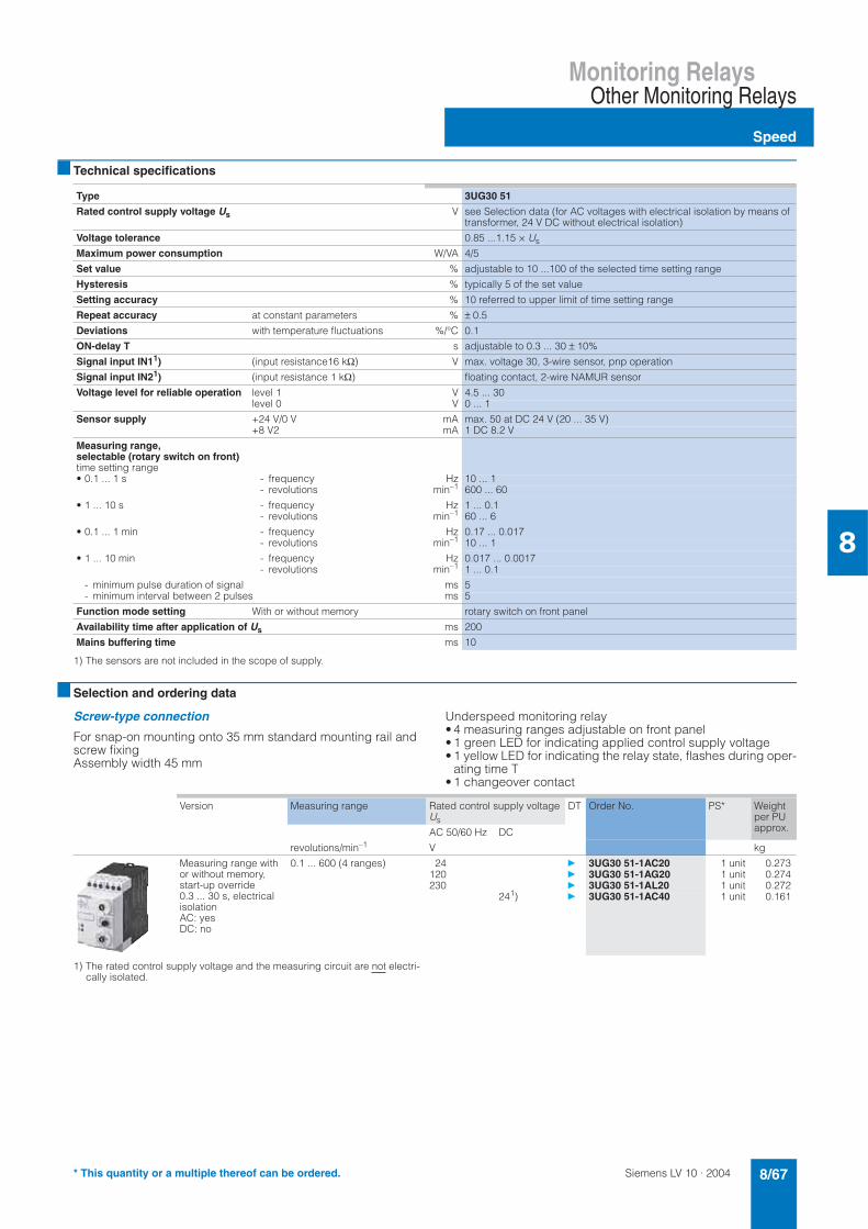
Siemens LV 10 · 2004 8/67
Monitoring RelaysOther Monitoring Relays
Speed
8
Technical specifications
1) The sensors are not included in the scope of supply.
Selection and ordering data
Screw-type connection
For snap-on mounting onto 35 mm standard mounting rail and screw fixing Assembly width 45 mm
Underspeed monitoring relay • 4 measuring ranges adjustable on front panel • 1 green LED for indicating applied control supply voltage • 1 yellow LED for indicating the relay state, flashes during oper-
ating time T • 1 changeover contact
1) The rated control supply voltage and the measuring circuit are not electri-cally isolated.
Type 3UG30 51
Rated control supply voltage Us V see Selection data (for AC voltages with electrical isolation by means of transformer, 24 V DC without electrical isolation)
Voltage tolerance 0.85 ...1.15 × Us
Maximum power consumption W/VA 4/5
Set value % adjustable to 10 ...100 of the selected time setting range
Hysteresis % typically 5 of the set value
Setting accuracy % 10 referred to upper limit of time setting range
Repeat accuracy at constant parameters % ± 0.5
Deviations with temperature fluctuations %/°C 0.1
ON-delay T s adjustable to 0.3 ... 30 ± 10%
Signal input IN11) (input resistance16 kΩ) V max. voltage 30, 3-wire sensor, pnp operation
Signal input IN21) (input resistance 1 kΩ) floating contact, 2-wire NAMUR sensor
Voltage level for reliable operation level 1 V 4.5 ... 30level 0 V 0 ... 1
Sensor supply +24 V/0 V mA max. 50 at DC 24 V (20 ... 35 V)+8 V2 mA 1 DC 8.2 V
Measuring range,selectable (rotary switch on front) time setting range• 0.1 ... 1 s - frequency Hz 10 ... 1
- revolutions min–1 600 ... 60
• 1 ... 10 s - frequency Hz 1 ... 0.1- revolutions min–1 60 ... 6
• 0.1 ... 1 min - frequency Hz 0.17 ... 0.017- revolutions min–1 10 ... 1
• 1 ... 10 min - frequency Hz 0.017 ... 0.0017- revolutions min–1 1 ... 0.1
- minimum pulse duration of signal ms 5- minimum interval between 2 pulses ms 5
Function mode setting With or without memory rotary switch on front panel
Availability time after application of Us ms 200
Mains buffering time ms 10
Version Measuring range Rated control supply voltage Us
DT Order No. PS* Weight per PU approx.AC 50/60 Hz DC
revolutions/min–1 V kg
Measuring range with or without memory, start-up override 0.3 ... 30 s, electrical isolationAC: yes DC: no
0.1 ... 600 (4 ranges) 24 3UG30 51-1AC20 1 unit 0.273120 3UG30 51-1AG20 1 unit 0.274230 3UG30 51-1AL20 1 unit 0.272
241) 3UG30 51-1AC40 1 unit 0.161
* This quantity or a multiple thereof can be ordered.

Siemens LV 10 · 20048/68
Coupling Relays and Converters
General data
Coupling Relays with Narrow Type of Construction
8
Circuit diagrams
Relay connectors – connection diagrams
Relay connectors – position of the terminals
Relay connectors – connection diagrams
Terminal designations acc. to EN 50005
3TX7 002-.A.00 3TX7 002-1AB02 3TX7 002-2AF05 3TX7 003-.A.00
-1B.00
-1B.00
-1CB00
1CB00
-1FB02 -2BF02
Output interfaces Input interfaces
3TX7 002-1AB0. 3TX7 003-1AB00
-1B.00-1B.00
-1CB00-1CB00
-1FB02 3TX7 002-2A.0. 3TX7 003-2A.0.
-2BF02
Output interfaces
3TX7 00.-1M.00 3TX7 00.-1AB10 3TX7 00.-1BB00 3TX7 00.-1BF05
3TX7 00.-1L.0.
3TX7 00.-1BB10 3TX7 00.-1CB00 3TX7 00.-1HB00 3TX7 00.-1GB00
Input interfaces
3TX7 00.-2M.02
A = automatic
0 = neutral position
M = manual

Siemens LV 10 · 2004 8/69
Coupling Relays and ConvertersCoupling Relays with Narrow Type of Construction
General data
8
Relay connectors – position of the terminals
Semiconductor interfaces – connection diagrams
Semiconductor interfaces – position of the interfaces
Output interfaces Input interfaces
3TX7 004-1M.00 -1L.0. -1AB10 -1B.0. -1BB10 -1CB00 -1HB00 -1GB00
3TX7 004-2M...
3TX7 005-1M.00 -1L.0. -1AB10 -1BB00 -1BB10 -1CB00 -1HB00 -1GB00
3TX7 005-2M...
Terminal designations acc. to EN 50005
3TX7 002-3AB00 -3AB01 -4AB00 -4AG00
Output interfaces Input interfaces
3TX7 002-3AB0. 3TX7 002-4A.0.

Siemens LV 10 · 20048/70
Coupling Relays and Converters
General data
Coupling Relays with Narrow Type of Construction
8
Semiconductor interfaces – connection diagrams
Semiconductor interfaces – position of the interfaces
A = automatic
0 = neutral position
M = manual
Output interfaces
3TX7 00.-3AB04 3TX7 00.-3PB41
3TX7 00.-3PB54 3TX7 00.-3PG74 3TX7 00.-3PB74
3TX7 00.-3AC04
3TX7 00.-3AC14 3TX07 00.-3AC03 3TX7 00.-3RB43
Input interfaces
3TX7 00.-4AB04 3TX7 00.-4P.24
Output interfaces Input interfaces
3TX7 004-3AB04, -3PB41
-3PB54,-3PB74,-3PG74
-3AC04 -3AC14 -3AC03 -3RB433TX7 004-4AB04 3TX7 004-4P.24
3TX7 005-3AB04, -3PB41
-3PB54,-3PB74,-3PG74
-3AC04 -3AC14 -3AC03 -3RB433TX7 005-4AB04 3TX7 005-4P.24

Siemens LV 10 · 2004 8/71
Coupling Relays and ConvertersCoupling Relays with Narrow Type of Construction
Relay connectors
8
Overview
AC and DC operation
DIN VDE 0110 Part 1, DIN VDE 0435, DIN VDE 0660 and EN 50005
In the coupling elements in double-decker format, the connec-tions are arranged on two levels; the units are extremely com-pact. Connection method: screw-type connection or spring-loaded terminal. For test purposes, versions are available with manual 0 automatic switches.
The input and output coupling elements differ with regard to the positioning of the terminals and the LEDs. For equipment identi-fication purposes, each coupling element has a blank legend plate.
In accordance with the technical specifications of electronic sys-tems, the coupling elements have a lower power consumption.
Design
Note on mounting
Snap-on mounting is possible on horizontal and vertical rails. In the case of vertical rails and closely mounted units, the maxi-mum permissible ambient temperature Tu = 40 °C. Any service position is possible.
If the coupling elements are operated continuously 24 hours per day (100% ON time) at the maximum permissible rated control supply voltage and the maximum permissible ambient tempera-ture, it is recommended that no similar equipment or other units that generate heat are placed directly adjoining the coupling el-ements because this can reduce the service life of the couplers.
A clearance of > 10 mm to the right and left of the coupling ele-ment reduces the risk of a premature failure under these condi-tions of application.
Functions
Surge suppression
The coupling links have been tested with 1 x 10⁵ operating cy-cles at AC-15 operation with the values specified in the Techni-cal specifications.
If inductive loads are connected, the service life of the relay con-nectors can be increased.
Note:
If capacitive loads without series resistors are switched, which limit temporary peak currents, microscopic welding of the relay contacts may result.
Connecting a lead to the spring-loaded terminals
!" !" "
"#$% &# # "

Coupling Relays and Converters
Relay connectors
Coupling Relays with Narrow Type of Construction
8
Siemens LV 10 · 20048/72
Technical specifications
1) For 3TX7 00.-1FB02, no safe isolation acc. to DIN VDE 0106 Part 101.
Note: If inductive loads are connected in parallel, the service life of the relay connectors can be increased.1) No safe isolation for 3TX7 00.-1FB02
2) Capacitive loads can result in micro-welding on the contacts
Type 3TX7 002-/3TX7 003-General dataRated insulation voltage Ui (pollution degree 3) V 300
Safe isolation 1)between the coil and the contacts acc. to DIN VDE 0106 Part 101
V up to AC 300 V
Degree of protection Connections IP20Enclosures IP30
Short-circuit protection acc. to IEC 60947-5-1 (weld-free protection at Ik ≥ 1 kA) Fuse-links, operational class gL/gG
A 4
Permissible ambient temperature during operation °C –25 ... +60during storage °C –40 ... +80
Conductor cross-sections• Screw-type connections
- solid mm2 1 × (0.25 ... 4)- finely stranded with or without end sleeve mm2 1 × (0.5 ... 2.5)- terminal screw M 3
• Spring-loaded terminals (for 3TX7 003):- solid or finely stranded mm2 1 × (0.08 ... 2.5)- finely stranded with end sleeve mm2 1 × (0.25 ... 1.5)
Type 3TX7 002-/3TX7 003- 1AB02 1AB00 1BB001FB02
1CB00 2AB00 2AE00 1BF002BF02
2AF00 2AF05
Control side • Operating range 0.8 ... 1.25 × Us 0.8 ... 1.1 × Us
• Power consumption at Us W 0.75 0.75 0.75 1.2 0.75 0.75 1.2 1.2 1.2
• Release voltage % of Us ≥ 10 ≥ 25
• Max. permissible conductor length (min. conductor cross-sec-tion: 0.75 mm2)
- AC m 300 300 300 300 300 15 7 7 350
- DC m 2000
• Permissible residual currentof the electronic circuit (for 0 signal)
mA 2 2 2 4 2 0.4 0.35 0.35 4
• Switching times at Us - ON-delay ms < 8- OFF-delay ms < 10
• Function display yellow LEDLoad side Rated currents2)• Conventional thermal current Ith A 6• Rated operating currents Ie acc. to utilization categories (DIN VDE 0660)
(3TX7 002-1CB00: AC-15, Ie = 2 A)- AC-15 - at 24 V A 3
- at 110 V A 3- at 230 V A 3
- DC-13 - at 24 V A 1.0- at 110 V A 0.2- at 230 V A 0.1
• Operating currentwith resistive load to DIN VDE 0435 (relay standard) and DIN VDE 0660- AC-12 - at 24 V A 6
- at 110 V A 6- at 230 V A 6
- DC-12 - at 24 V A 6- at 110 V A 0.2- at 230 V A 0.2
• Operating voltage - AC/DC V 24 ... 250
• Min. contact load for 3TX7 00.-...02 mA AC/DC 1 V, 0.1
• Mechanical endurance Oper.cycles
20 × 106
• Electrical endurance at Ie Oper.cycles
1 × 10⁵
• Operating frequency Oper.cycles
1/h
5000
• Contact material for 3TX7 00.-...02 Ag/Ni 0.15 hard gold-plated
• Power limit hard gold plating for 3TX7 00.-...02- Voltage V 30- Current mA 20

Siemens LV 10 · 2004 8/73
Coupling Relays and ConvertersCoupling Relays with Narrow Type of Construction
Relay connectors
8
Note: If inductive loads are connected in parallel, the service life of the relay connectors can be increased.1) Capacitive loads can result in micro-welding on the contacts
Type 3TX7 004/3TX7 005
General dataRated insulation voltage Ui (pollution degree 3) V 300
Safe isolation between the coil and the contacts acc. to DIN VDE 0106 Part 101
AC V up to 300
Degree of protection Connections IP20Enclosures IP30
Short-circuit protection acc. to IEC 60947-5-1 (weld-free protection at Ik ≥ 1 kA) fuse-links, operational class gL/gG
A 4
Permissible ambient temperature during operation °C –25 ... +60during storage °C –40 ... +80
Conductor cross-sections• Screw connections (for 3TX7 004):
- solid mm2 1 × (0.25 ... 4)- finely stranded with end sleeve mm2 1 × (0.5 ... 2.5)- finely stranded without end sleeve mm2 1 × (0.5 ... 2.5)- terminal screws M 3
• Spring-loaded terminals (for 3TX7 005):- solid or finely stranded mm2 1 × (0.08 ... 2.5)- finely stranded with end sleeve mm2 1 × (0.25 ... 1.5)
Control side • Operating range at DC 17 ... 40 V –
at Us = AC/DC 24 V 0.7 ... 1.25 × Usat Us = AC/DC 110 and 230 V 0.8 ... 1.1 × Us
• Power consumption at Us approx. 0.5 W/channel; 3TX7 00.-...05: 1 W at DC/6 VA at AC
• Permissible residual current of the electronics (for 0 signal)- Width 6.2 mm- Us = 24 V mA 2- Us > 24 V mA 0.5- From 12.5 mm width
Exceptions: 3TX700.-1LH00, 3TX700.-1BF05
mA
mAmAmA
2.5
1.55 (Us = AC 230 V)0.5 (Us = AC 230 V)
• Switching times at Us - ON-delay ms < 8- OFF-delay ms < 15
• Function display yellow LED
Type 3TX7 004/3TX7 005 -1.F00-2ME02-2MF02
-1.B..-2MB02
1.H0. -1BF05
Max. permissible conductor length(min. conductor cross-section: 0.75 mm2)
• AC m 40 400 on request 350• DC m 2000 2000 on request 2000
Type 3TX7 00.-1A/1B-/1C/-1H/1G 3TX7 00.-.L/.MLoad side Rated operating currents Ie
1)• Conventional thermal current Ith A 6 6• Rated operating current Ie
according to utilization categories (DIN VDE 0660)- AC-15 - at 24 V A 3 2
- at 110 V A 3 2- at 230 V A 3 2
- DC-13 - at 24 V A 1 1- at 110 V A 0.2 0.2- at 230 V A 0.1 0.1
• Operating current with resistive load to DIN VDE 0435 (relay standard) and DIN VDE 0660
- AC-12 - at 24 V A 6 6- at 110 V A 6 6- at 230 V A 6 6
- DC-12 - at 24 V A 6 6- at 110 V A 0.3 0.3- at 230 V A 0.2 0.2
• Power limit/hard gold plating - Voltage V 30 30- Current mA 20 20
• Operating voltage AC/DC V 17 ... 250 17 ... 250
• Endurance - mechanical Operating cycles 20 × 106 20 x 106
- electrical (at Ie) Operating cycles 1 × 10⁶ 0.5 x 10⁶
• Operating frequency Operating cycles1/h
5000 5000

Coupling Relays and Converters
Relay connectors
Coupling Relays with Narrow Type of Construction
8
Siemens LV 10 · 20048/74
Selection and ordering data
AC and DC operation • for snap-on mounting onto 35 mm standard mounting rail
Note:
For coil voltages which are not listed, see DC power supplies SITOP power e.g. 6EP1 331-2BA10 and 6EP1 731-2BA00 in "Transformers and power supplies".
1) The same potential must be applied to 2 NO/2 CO relays.
2) Observe max. permissible conductor length, see Technical specifications.
Rated control supply voltage Us
ContactsVersion
Width DT Screw-type connection
PS* Weight per PU approx.
DT Spring-loaded terminal
PS* Weight per PU approx.
AC 50/60 Hz S W mm Order No. kg Order No. kg3TX7 002 and 3TX7 003 relay connectors
Output interfaces
3TX7 002
AC/DC 24 V 1 – 11.5 3TX7 002-1AB00 1 unit 0.032 3TX7 003-1AB00 1 unit 0.030AC/DC 24 V 1 (hard
gold-plated)
– 3TX7 002-1AB02 1 unit 0.032 –
AC/DC 24 V – 1 17.5 3TX7 002-1BB00 1 unit 0.043 3TX7 003-1BB00 1 unit 0.038AC/DC 230 V – 1 3TX7 002-1BF00 1 unit 0.044 A 3TX7 003-1BF00 1 unit 0.039AC/DC 24 V 21) – 22.5 3TX7 002-1CB00 1 unit 0.055 3TX7 003-1CB00 1 unit 0.050AC/DC 24 V – 2 (hard
gold-plated)1)
3TX7 002-1FB02 1 unit 0.055 –
3TX7 002
Input interfacesAC/DC 24 V 1 – 11.5 3TX7 002-2AB00 1 unit 0.032 A 3TX7 003-2AB00 1 unit 0.030AC/DC 110 V 1 – 3TX7 002-2AE00 1 unit 0.032 –
AC/DC 230 V1) 1 – 11.5 3TX7 002-2AF00 1 unit 0.033 A 3TX7 003-2AF00 1 unit 0.031AC/DC 230 V1) 1 – 3TX7 002-2AF05 1 unit 0.038 –AC/DC 230 V – 1 (hard
gold-plated)2)
17.5 3TX7 002-2BF02 1 unit 0.043 –
* This quantity or a multiple thereof can be ordered.

Siemens LV 10 · 2004 8/75
Coupling Relays and ConvertersCoupling Relays with Narrow Type of Construction
Relay connectors
8
Note:
For replacement products, see interfaces with 3RS18 industrial enclosure or other 3TX70 products.
For coil voltages which are not listed, see DC power supplies SITOP power e.g. 6EP1 331-2BA10 and 6EP1 731-2BA00 in "Transformers and power supplies".
1) For long conductors.
Rated control supply volt-age Us
Contacts Chan-nel
Manual-0-auto-maticswitch for test-ing pur-poses
Width DT Screw-type connection
PS* Weight per PU approx.
DT Spring-loadedterminal
PS* Weight per PU approx.
Version
AC 50/60 Hz S W mm Order No. kg Order No. kgRelay connectors 3TX7 004 and 3TX7 005
Output interfaces
3TX7 004-1LB0.
AC/DC 24 V – 1 1 without 6.2 3TX7 004-1LB00 1 unit 0.033 3TX7 005-1LB00 1 unit 0.029
AC/DC 230 V – 1 1 without 6.2 3TX7 004-1LF00 1 unit 0.035 3TX7 005-1LF00 1 unit 0.030
AC/DC 230 V – 1 1 without 12.51) 3TX7 004-1BF05 1 unit 0.057 A 3TX7 005-1BF05 1 unit 0.053
DC 17/40 V – 1 1 without 6.2 3TX7 004-1LH00 1 unit 0.033 A 3TX7 005-1LH00 1 unit 0.029
AC/DC 24 V – 1 (hard gold-plated)
1 without 6.2 3TX7 004-1LB02 1 unit 0.033 3TX7 005-1LB02 1 unit 0.028
AC/DC 24 V 1 – 1 without 6.2 3TX7 004-1MB00 1 unit 0.038 3TX7 005-1MB00 1 unit 0.034
AC/DC 230 V 1 – 1 without 6.2 3TX7 004-1MF00 1 unit 0.037 3TX7 005-1MF00 1 unit 0.034
AC/DC 24 V – 1 1 with 12.5 3TX7 004-1BB10 1 unit 0.052 C 3TX7 005-1BB10 1 unit 0.048
Input interfaces
3TX7 005-2MB02
AC/DC 24 V 1 (hard gold-plated)
– 1 without 6.2 3TX7 004-2MB02 1 unit 0.037 C 3TX7 005-2MB02 1 unit 0.034
AC/DC 110 V 1 (hard gold-plated)
– 1 without 6.2 3TX7 004-2ME02 1 unit 0.037 C 3TX7 005-2ME02 1 unit 0.031
AC/DC 230 V 1 (hard gold-plated)
– 1 without 6.2 3TX7 004-2MF02 1 unit 0.038 C 3TX7 005-2MF02 1 unit 0.034
* This quantity or a multiple thereof can be ordered.

Coupling Relays and Converters
Relay connectors
Coupling Relays with Narrow Type of Construction
8
Siemens LV 10 · 20048/76
Accessories
For interface Version DT Order No. PS* Weight per PU approx.
Type kgConnecting comb
3TX7 004 24 terminals, blue, width 6.2 mm 3TX7 004-8AA00 1 unit 0.017
Connecting lead3TX7 002, 3TX7 003, 3TX7 004, 3TX7 005
24 terminals with supply cable, blue A 3TX7 004-8BA00 1 unit 0.050
* This quantity or a multiple thereof can be ordered.
Siemens LV 10 · 2004 8/77
Coupling Relays and ConvertersCoupling Relays with Narrow Type of Construction
Plug-in relay connectors
8
Benefits
The wire is fed in and screwed down from the front. This results in faster wiring time and wiring errors are prevented.
Overview
Coupling elements are used to connect signals to and from a PLC. The plug-in relays enable the relay to be replaced at the end of its service life without the need for any changes in the wir-ing.
For easy bridging of the signals, each terminal can be jumpered using an external connecting comb.
Technical specifications
Note: If inductive loads are connected in parallel, the service life of the relay connectors can be increased.
1) Capacitive loads can result in micro-weldings on the contacts
2) 1 ppm = one fault per one million operating cycles.
Type 3TX7 01.-1General dataRated insulation voltage Ui (pollution degree 3) V 300
Safe isolation between the coil and the contacts acc. to DIN VDE 0106 Part 101
V up to AC 300 V
Degree of protection Connections IP20Enclosures IP40
Short-circuit protection acc. to IEC 60947-5-1 (weld-free protection at Ik ≥ 1 kA) Fuse-links, operational class gL/gG
A 4
Permissible ambient temperature during operation °C –25 ... +55during storage °C –40 ... +80
Conductor cross-sections• Screw connections
- solid mm2 1 × (0.5 ... 2.5)- finely stranded with or without end sleeve mm2 1 × (0.5 ... 1.5)- terminal screw M 3
Type 3TX7 01.-1.M 3TX7 01.-1.B 3TX7 01.-1.E/FControl side • Operating range 0.9 ... 1.1 × Us 0.7 ... 1.25 × Us 0.8 ... 1.1 × Us
• Power consumption at Us W 0.5
• Release voltage % of Us 10
• Max. permissible conductor length (min. conductor cross-sec-tion: 0.75 mm)
- AC m 7- DC m 2000
• Permissible residual currentof the electronic circuit (for 0 signal)
mA 2 2 0.4
• Operating times at Us - ON-delay ms < 5 < 7 < 8- OFF-delay ms < 5 < 7 < 13
• Function display yellow LED
• Protection circuit- DC flywheel diode +
reverse voltage protec-tion
- AC Varistor
Type 3TX7 01.-1Load side Rated currents1)• Conventional thermal current Ith A 5• Rated operating currents Ie
- AC-15 - at 24 V A 3- at 110 V A 3- at 230 V A 3
- DC-13 - at 24 V A 1- at 110 V A 0.2- at 230 V A 0.1
• Operating voltage AC/DC V 24 ... 250
• Min. contact load- standard contact AC/DC 17 V, 5 mA at 1 ppm fault2)- hard gold-plated contacts AC/DC 5 V, 1 mA for 1 ppm fault2)
• Mechanical endurance Operat-ing
cycles
20
• Electrical endurance for Ieacc. to AC-15
Operat-ing
cycles
100000
• Operating frequency Operat-ing
cycles1/h
5000

Siemens LV 10 · 20048/78
Coupling Relays and Converters
Plug-in relay connectors
Coupling Relays with Narrow Type of Construction
8
Selection and ordering data
Note:Start of delivery of the socket interfaces with screw-type connec-tion, expected at the beginning of 2004, units with spring-loaded terminals at the end of 2004.
1) The variants with hard gold-plated contacts with high contact reliability (also for low currents) are especially suitable for electronic inputs of pro-grammable logic controllers.
2) The order number is not printed on the relays.
Rated control supply voltage Us
Contacts DT Screw connection PS* Weight per PU approx.
S W Order No. kgPlug-in interface, complete with relay
3TX7014-1BM00
DC 24 V 1 – A 3TX7 014-1AM00 1 unit 0.035DC 24 V – 1 A 3TX7 014-1BM00 1 unit 0.035
AC/DC 24 V – 1 A 3TX7 014-1BB00 1 unit 0.035
AC/DC 115 V – 1 A 3TX7 014-1BE00 1 unit 0.045
AC/DC 230 V – 1 A 3TX7 014-1BF00 1 unit 0.045
Plug-in base interface, complete with relay and hard gold-plating1)DC 24 V – 1 hard gold-plated A 3TX7 014-1BM02 1 unit on
request
AC/DC 24 V – 1 hard gold-plated A 3TX7 014-1BB02 1 unit 0.035
AC/DC 115 V – 1 hard gold-plated A 3TX7 014-1BE02 1 unit onrequest
AC/DC 230 V – 1 hard gold-plated A 3TX7 014-1BF02 1 unit onrequest
Coil voltage Used for DT Order No. PS* Weight per PU approx.
kg
Individual relay modules2), 1 changeover contactDC 24 V Complete unit DC 24 V A 3TX7 014-7BQ00 1 unit on
requestDC 24 V Complete unit, DC 24 V, hard gold-plated A 3TX7 014-7BQ02 1 unit on
request
DC 24 V Complete unit AC/DC 24 V A 3TX7 014-7BM00 1 unit 0.035DC 24 V Complete unit, DC 24 V, hard gold-plated A 3TX7 014-7BM02 1 unit 0.035
DC 24 V Complete unit AC/DC 115 V and 230 V A 3TX7 014-7BP00 1 unit onrequest
DC 24 V Complete unit AC/DC 115 V and 230 V, hard gold-plated A 3TX7 014-7BP02 1 unit onrequest
Connecting comb 16-pole, bluefor jumpering the same potentials, 16-pole, 6 A current-carrying capacity A 3TX7 014-7AA00 1 unit on
request
* This quantity or a multiple thereof can be ordered.

Siemens LV 10 · 2004 8/79
Coupling Relays and ConvertersCoupling Relays with Narrow Type of Construction
Semiconductor couplers
8
Area of application
AC and DC operation
DIN VDE 0110 Part 1, DIN VDE 0435, DIN VDE 0660 and EN 50 005 optocoupler: DIN VDE 0884, DIN VDE 0411 Part 500, IEC 61131-2 (programmable logic controllers).
In the coupling elements in double-decker format, the connec-tions are arranged on two levels; the units are extremely com-pact. Connection method: screw-type connection or spring-loaded terminal. For test purposes, versions are available with manual 0 automatic switches.
The input and output coupling elements differ with regard to the positioning of the terminals and the LEDs. For equipment identi-fication purposes, each coupling element has a blank legend plate.
In accordance with the technical specifications of electronic sys-tems, the coupling elements have a lower power consumption.
Design
Note on mounting
Snap-on mounting is possible on horizontal and vertical rails. In the case of vertical rails and closely mounted units, the maxi-mum permissible ambient temperature Tu = 40 °C. Any service position is possible.
If the coupling elements are operated continuously 24 hours per day (100% ON time) at the maximum permissible rated control supply voltage and the maximum permissible ambient tempera-ture, it is recommended that no similar equipment or other units that generate heat are placed directly adjoining the coupling el-ements because this can reduce the service life of the couplers.
A clearance of > 10 mm to the right and left of the coupling ele-ment reduces the risk of a premature failure under these condi-tions of application.
Optocouplers switch using semiconductors. These are not sub-ject to wear; welding is not possible.
The 6.2 mm wide optocouplers have an opening in the right-hand side of the casing. They can, like relay connectors, be mounted side-by-side without gaps.
Functions
Surge suppression
In the case of optocouplers, the contact element is a semicon-ductor. These are not subject to wear; so welding is not possible.
With semiconductors, the switching current is not dependent on the inductance of the load, i.e. the switching current for a DC-13 load is the same as that for an inductive DC-12 load. This means that coupling elements with a semiconductor output are particu-larly suitable for inductive loads such as solenoid valves. It is not relevant to specify the number of operating cycles because this does not affect the service life of the semiconductor provided it is not overheated.
To provide shock-hazard protection in the case of modules of 6.2 mm width (e.g. 3TX7 004-3AB04) with an opening in the casing, the single module or the last module in a row must be fitted with a cover plate.
Connecting a lead to the spring-loaded terminals
!" !" "
"#$% &# # "

Siemens LV 10 · 20048/80
Coupling Relays and Converters
Semiconductor couplers
Coupling Relays with Narrow Type of Construction
8
Technical specifications
1) Observe minimum operating voltage for 3TX7 002-3AB00.
Type 3TX7 002/3TX7 003General dataDerating diagram for 3TX7 002-3AB01 Load current depending on ambient temperature Tu
Rated insulation voltage Ui(pollution degree 3)
V 300
Optoelectronic coupling element for safe isolation acc. toDIN VDE 0660 Part 101
V ... 300
Conductor cross-sectionssolid mm2 1 × (0.25 ... 4)finely stranded with or without end sleeve
mm2 1 × (0.5 ... 2.5)
terminal screws M 3
Permissible ambient temperatureduring operation °C –25 ... +60during storage °C –40 ... +80
'
()
(*)
+,
+, " "
-$#,--#" """$. #"
"#
/,
/,
Type 3TX7 002- 3AB00 3AB01 4AB00 4AG00Control sideOperating range V DC 17 ... 30 DC 11 ... 30 AC/DC 17 ... 30 AC 88 ... 264
Control side current input • at DC 17 V mA < 18 < 5 – –• at DC 24 V mA < 20 < 7 – –• at DC 30 V mA < 22 < 8.5 – –• at AC/DC 17 V mA – – < 10 –• at AC/DC 24 V mA – – < 14 –• at AC/DC 30 V mA – – < 18 –• at AC 88 V mA – – – < 9• at AC 230 V mA – – – < 24• at AC 264 V mA – – – < 28
Release voltage V > 5 > 8 > 5 > 40
Operating times• ON-delay at DC 17 V ms < 10 < 0.1 – –
at DC 24 V ms < 10 < 0.1 – –at DC 30 V ms < 10 < 0.1 – –at AC/DC 17 V ms – – < 1 –at AC/DC 24 V ms – – < 1 –at AC/DC 30 V ms – – < 1 –at AC 88 V ms – – – < 18at AC 230 V ms – – – < 20at AC 264 V ms – – – < 22
• OFF-delay at DC 17 V ms < 10 < 0.1 < 18 –at DC 24 V ms < 10 < 0.1 < 25 –at DC 30 V ms < 10 < 0.1 < 30 –at AC/DC 17 V ms – – < 18 –at AC/DC 24 V ms – – < 25 –at AC/DC 30 V ms – – < 30 –at AC 88 V ms – – – < 10at AC 230 V ms – – – < 20at AC 264 V ms – – – < 25
Function display yellow LED yellow LED yellow LED yellow LED
Max. permissible conductor length(min. conductor cross-section:0.75 mm2)
AC m – – 1000 140DC m 2000 2000 2000 –
Load side • Rated operating current Ie A 1.8 1.5
(see derating diagram)
0.1 0.1
• Short-time loading capacity A 20 4 1 1ms 20 0.2 20 20
• Contacts 1 NO, Triac 1 NO, transistor 1 NO, transistor 1 NO, transistor
• Switching voltage1)(working range)
effective AC 50/60 Hz V 48 ... 264DC V ≤ 60 ≤ 30 ≤ 60
• Minimum load current mA 60 – – –
• Voltage drop (conducting) V ≤ 1.5 ≤ 1.1 ≤ 1.7 ≤ 0.3
• Leakage current of the electronics (for 0 signal) mA < 5 < 0.1 < 0.1 < 0.001
• Operating frequency at Ie Hz 1 1 5 5

Siemens LV 10 · 2004 8/81
Coupling Relays and ConvertersCoupling Relays with Narrow Type of Construction
Semiconductor couplers
8
1) In the event of a short-circuit or overload, the semiconductor output switches off. In order to operate the unit again, it must be temporarily dis-connected from the power supply.
2) In the event of a short-circuit or overload, the current is limited by the semi-conductor output.
3) If the current falls below the minimum load current, the built-in semicon-ductor detects an open-circuit in the load circuit. The control must be tem-porarily switched off for resetting.
Type 3TX7 004/3TX7 005General dataRated insulation voltage Ui (pollution degree 3) V 300
Safe isolation acc. to DIN VDE 0106 Part 101 V ... 300
Permissible ambient temperature
• during operation °C – 25 ... + 60• during storage °C – 40 ... + 80
Conductor cross-sections• Screw connections (for 3TX7 004):
- solid mm2 1 × (0.25 ... 4)- finely stranded with end sleeve mm2 1 × (0.5 ... 2.5)- finely stranded without end sleeve mm2 1 × (0.5 ... 2.5)- terminal screws M 3
• Spring-loaded terminals (for 3TX7 005):- solid or finely stranded mm2 1 × (0.08 ... 2.5)- finely stranded with end sleeve mm2 1 × (0.25 ... 1.5)
Type 3TX7 004-/3TX7 005-
3AB04/4AB04
3AC.4 3AC03 3PB54 4PG24
Control side • Operating range V 11 ... 30 DC 11 ... 30 DC 11 ... 30 DC 11 ... 30 DC 110 ... 230
AC/DC
• Power consumption- at DC 24 V W ≤ 0.5 ≤ 0.5 ≤ 0.25 ≤ 0.2 –- at AC 230 V W – – – – ≤ 1.5
• Release voltage V 6 5 6 9 20
• Permissible residual current of the electronic circuit (for 0 signal)
mA 2.3 2.6 1.5 1.5 0.4
• Operating times- ON-delay ms 2.5 0.3 10 0.3 1- OFF-delay ms 8 4 10 0.3 6
• Function display yellow LED yellow LED yellow LED yellow LED yellow LED
• Max. permissible conductor length(min. conductor cross-section: 0.75 mm2)
m 1700 2000 2000 2000 40
Load side Operating voltage V ≤ 48 DC ≤ 30 DC 24 ... 250 V AC ≤ DC 30 V ≤ DC 30 V
Operating current A 0.5 5 2 1.5 0.1
• Short-time loading capacityA 1.5 Short-circuit
resistant1)100 Short-circuit
resistant2)0.2
ms 20 20 3
• Contacts 1 NO contact, transistor
1 NO contact, transistor
1 NO contact, triac
1 NO contact, transistor
1 NO contact, transistor
• Minimum load current mA – 5003) 50 – –
• Voltage drop (conducting) V ≤ 1 ≤ 0.5 ≤ 1.6 ≤ 0.5 ≤ 1.5
• Leakage current for 0 signal mA < 0.1 < 0.1 < 6 < 0.1 < 0.1
• Operating frequency for resistive load Hz 50 50 1 500 500

Siemens LV 10 · 20048/82
Coupling Relays and Converters
Semiconductor couplers
Coupling Relays with Narrow Type of Construction
81) In the event of a short-circuit or overload, the current is limited by the semi-
conductor output.
Type 3TX7 004-/3TX7 005-
3P.74 3PB41 3RB43 4PB24
Control side • Operating range V 110 ... 230 AC/DC 11 ... 30 DC 18 ... 30 DC 11 ... 30 DC
• Power consumption- at DC 24 V W – ≤ 0.5 ≤ 0.3 ≤ 0.2- at AC 230 V W ≤ 1.5 – – –
• Release voltage V 25 5 12 6
• Permissible residual current of the electronic circuit (for 0 signal) mA 1 1.5 4 1.2
• Operating times- ON-delay ms 1.5 4 0.2 0.2- OFF-delay ms 75 6 10 1
• Function display yellow LED yellow LED yellow LED yellow LED
• Max. permissible conductor length(min. conductor cross-section: 0.75 mm2)
m 40 2000 2000 2000
Load side Operating voltage V ≤ DC 30 ≤ DC 200 AC 24 ... 250 ≤ DC 30
Operating current A 3 0.75 0.5 0.1
• Short-time loading capacityA Short-circuit
resistant1)3 0.8 0.2
ms 2 3 3
• Contacts 1 NO contact, transistor
1 NO contact, transistor
1 NO contact, triac
1 NO contact, transistor
• Minimum load current mA – – 10 –
• Voltage drop (conducting) V ≤ 0.5 ≤ 2 ≤ 1.5 ≤ 1.5
• Leakage current of the electronics (for 0 signal) mA ≤ 0.1 ≤ 0.1 ≤ 1 ≤ 0.1
• Operating frequency for resistive load Hz 10 50 50 500

Siemens LV 10 · 2004 8/83
Coupling Relays and ConvertersCoupling Relays with Narrow Type of Construction
Semiconductor couplers
8
Selection and ordering data
AC and DC operation • for snap-on mounting onto 35 mm standard mounting rail
Note:
For replacement products, see interfaces with 3RS18 industrial enclosure or other 3TX70 products.
For coil voltages which are not listed, see DC power supplies SITOP power e.g. 6EP1 331-2BA10 and 6EP1 731-2BA00 in "Transformers and power supplies".1) Discontinued products: will no longer be manufactured from the beginning
of 2004.
Rated control supply voltage Us
Contacts Width DT Screw connection PS* Weight per PU approx.
DT Spring-loadedterminal
PS* Weight per PU approx.
Version
AC 50/60 Hz mm Order No. kg Order No. kg3TX7 002 semiconductor interfaces
3TX7 002
Output interfaces DC 24 V 1 triac – 12.5 3TX7 002-3AB00 1 unit 0.033 –
1 triac – 11.5 3TX7 002-3AB01 1 unit 0.035 –
Input interfaces AC/DC 24 V 1 transistor – 12.5 3TX7 002-4AB00 1 unit 0.031 –AC 110 ... 240 V 1 transistor – 12.5 3TX7 002-4AG00 1 unit 0.035 –
Control Operatingvoltage
Oper-atingcurrent
Manual-0-auto-maticswitch for testing purposes
Width DT Screw connection PS* Weight per PU approx.
DT Spring-loadedterminal
PS* Weight per PU approx.
AC 50/60 Hz A mm Order No. kg Order No. kg3TX7 004 and 3TX7 005 semiconductor interfaces
3TX7 004-3AB04 with cover plate
Output interfaces
DC 24 V ≤ 48 V DC 0.5 without 6.2 3TX7 004-3AB04 1 unit 0.034 3TX7 005-3AB04 1 unit 0.031
DC 24 V ≤ DC 30 V 1.5 without 6.2 3TX7 004-3PB54 1 unit 0.029 3TX7 005-3PB54 1 unit 0.024
DC 24 V ≤ DC 30 V 3 without 6.2 3TX7 004-3PB74 1 unit 0.032 A 3TX7 005-3PB74 1 unit 0.027
AC/DC 110 ... 230 V
≤ DC 30 V 3 without 6.2 3TX7 004-3PG74 1 unit 0.033 A 3TX7 005-3PG74 1 unit 0.027
DC 24 V ≤ DC 30 V 5 without 12.5 3TX7 004-3AC04 1 unit 0.056 3TX7 005-3AC04 1 unit 0.047
DC 24 V ≤ DC 30 V 5 with 12.5 C 3TX7 004-3AC14 1 unit 0.053 C 3TX7 005-3AC14 1 unit 0.051
DC 24 V ≤ 200 V DC 0.75 without 6.2 3TX7 004-3PB41 1 unit 0.035 A 3TX7 005-3PB41 1 unit 0.032
DC 24 V 24 ... 250 V AC
0.5 without 6.2 3TX7 004-3RB43 1 unit 0.041 A 3TX7 005-3RB43 1 unit 0.032
DC 24 V 24 ... 250 V AC
2 without 12.5 3TX7 004-3AC03 1 unit 0.060 C 3TX7 005-3AC03 1 unit 0.056
Input interfaces
AC/DC 110 ... 230 V
≤ DC 30 V 0.1 without 6.2 3TX7 004-4PG24 1 unit 0.034 3TX7 005-4PG24 1 unit 0.031
DC 24 V ≤ DC 30 V 0.1 without 6.2 3TX7 004-4PB24 1 unit 0.034 A 3TX7 005-4PB24 1 unit 0.031
DC 24 V1) ≤ 48 V DC 0.5 without 6.2 C 3TX7 004-4AB04 1 unit 0.034 C 3TX7 005-4AB04 1 unit 0.034
* This quantity or a multiple thereof can be ordered.

Siemens LV 10 · 20048/84
Coupling Relays and Converters
Semiconductor couplers
Coupling Relays with Narrow Type of Construction
8
For interface Version DT Order No. PS* Weight per PU approx.
Type kgConnecting comb
3TX7 004 24 terminals, blue, width 6.2 mm 3TX7 004-8AA00 1 unit 0.017
Connecting lead3TX7 002, 3TX7 003, 3TX7 004, 3TX7 005
24 terminals with supply, blue A 3TX7 004-8BA00 1 unit 0.050
Cover plate3TX7 004-3AB04, 3TX7 004-4AB04, 3TX7 005-3AB04, 3TX7 005-4AB04, 3TX7 005-4PB24
RAL 7035, light gray 3TX7 004-8CE00 1 unit 0.016
* This quantity or a multiple thereof can be ordered.

Siemens LV 10 · 2004 8/85
Coupling Relays and ConvertersCoupling Relays in Industrial Enclosure
Relay connectors
8
Overview
The new 3 RS18 coupling relays are couplers in the well-proven standard 22.5 mm time-delay relay enclosure. The series com-prises relays with 1, 2 and 3 changeover contacts with screw-type and spring-loaded terminals for combined voltages and wide voltage ranges.
Benefits
• Wide voltage range: one product for all voltages• The industrial enclosure supports the same connection meth-
ods as the time-delay relay including spring-loaded terminals, 2 wires can be clamped
• Versions with electronically optimized outputs (gold-plated)• Up to 3 changeover contacts with only 22.5 mm width.
Area of application
Typical applications are found wherever electronically optimized contacts are required and equipment with a wide voltage range is implemented.
Technical specifications
Type 3RS18..-....1 3RS18..-....0General dataRated insulation voltage Ui pollution degree 3 V 300
Safe isolation acc. to DIN VDE 0106 between the coil and the contacts V 300
Degree of protection acc. to EN 60529• Enclosure IP20• Cover IP40
Permissible ambient temperature• during operation °C –25 ... +60• during storage °C –40 ... +80
Permissible mounting position any
Shock resistance Half-sine acc. to IEC 60028-2-27
15/11
Vibration resistance acc. to IEC 60068-2-6
10 ... 55/0.35
Electromagnetic compatibility (EMC) Tests according to basic specification
IEC 61000-6-2/IEC 61000-6-4
Conductor cross-section• Screw connection
- Solid mm2 1 × (0.5 ... 4)/2 × (0.5 ... 2.5)- Finely stranded with end sleeve mm2 2 × (0.5 ... 2.5)- AWG conductors,
solid or strandedmm2 2 × (20 ... 14)
- Terminal screw M 3.5- Tightening torque Nm 0.8 ... 1.2- Corresponding opening tool Standard screwdriver, size 2 or Pozidrive 2
• Spring-loaded terminal- Solid mm2 2 × (0.25 ... 1.5)- Finely stranded with end sleeve mm2 2 × (0.25 ... 1)- Finely stranded without end
sleevemm2 2 × (0.25 ... 1.5)
- AWG conductors, solid or stranded
AWG 2 × (24 ... 16)
- Corresponding opening tool Screwdriver with 3 mm blade or 8WA2 807 opening tool
Control side • Operating range 0.85 ... 1.1 × Us
• Rated power- max. DC W 1- max. AC VA 8
• Mains buffering- depends on version ms 5 ... 100
• Max. permissible conductor length 2/3 changeover contact 1 changeover contact- 330 pF/m AC m 200 100- min. cross-section 0.75 mm2 DC m 1500 2000
• Permissible OFF-state currentof the electronic circuit (for 0 signal)
mA 2
• Function display yellow LED

Siemens LV 10 · 20048/86
Coupling Relays and Converters
Relay connectors
Coupling Relays in Industrial Enclosure
8
Selection and ordering data
1) Hard gold-plated.
Type 3RS18..-....1 3RS18..-....0Load side • Conventional thermal current Ith A 6
• Rated operating currents Ie- AC-15
- at 24 V A 3- at 110 V A 3- at 230 V A 3- at 400 V A 3
- DC-13- at 24 V A 1- at 110 V A 0.2- at 230 V A 0.1
• Operating current for resistive load- AC-12
- at 24 V A 5- at 115 V A 5- at 230 V A 5- at 400 V A 5
- DC-12- at 24 V A 5- at 115 V A 0.2- at 230 V A 0.2
• Operating voltage- max. AC V 400- max. DC V 250
• Contact material AgNi 0.15 hard gold-plated AgSnO2
• Min. contact load- Standard contact – DC 17 V, 5 mA for 1ppm fault- Hard gold-plated contacts DC 5 V, 1 mA for 1ppm fault –
• Endurance- Mechanical operating cycles 20 × 106
- Electrical (at Ie) operating cycles 1 × 10⁶
• Operating times- max. ON-delay at Us ms 8 (for 3RS18 00-..W0. < 30)- max. OFF-delay at Us ms 30 (for 3RS18 00-..W0. < 150)
• Operating frequency Oper.cycles/
h
5000
Short-circuit protection Weld-free fuse, operational class gL/gG at Ik ≥ 1 kA
A 4
Rated control supply voltage Us
ContactsVersion
DT Screw connection PS* Weight per PU approx.
DT Spring-loaded terminal PS* Weight per PU approx.
50/60 Hz W Order No. kg Order No. kgCoupling relays in 22.5 mm industrial enclosure
Wide-range voltage 24 ... 240 V AC/DC 2 B 3RS18 00-1BW00 1 unit 0.145 B 3RS18 00-2BW00 1 unit 0.128
3 B 3RS18 00-1HW00 1 unit 0.170 B 3RS18 00-2HW00 1 unit 0.14731) B 3RS18 00-1HW01 1 unit 0.170 B 3RS18 00-2HW01 1 unit 0.147
Combination voltage AC/DC 24 V and AC 110 ... 120 V
1 B 3RS18 00-1AQ00 1 unit 0.116 B 3RS18 00-2AQ00 1 unit 0.1042 B 3RS18 00-1BQ00 1 unit 0.142 B 3RS18 00-2BQ00 1 unit 0.1233 B 3RS18 00-1HQ00 1 unit 0.173 B 3RS18 00-2HQ00 1 unit 0.14731) B 3RS18 00-1HQ01 1 unit 0.173 B 3RS18 00-2HQ01 1 unit 0.147
AC/DC 24 V and AC 220 ... 240 V
1 B 3RS18 00-1AP00 1 unit 0.116 B 3RS18 00-2AP00 1 unit 0.1042 B 3RS18 00-1BP00 1 unit 0.142 B 3RS18 00-2BP00 1 unit 0.1233 B 3RS18 00-1HP00 1 unit 0.170 B 3RS18 00-2HP00 1 unit 0.14731) B 3RS18 00-1HP01 1 unit 0.170 B 3RS18 00-2HP01 1 unit 0.147
* This quantity or a multiple thereof can be ordered.

Siemens LV 10 · 2004 8/87
Coupling Relays and ConvertersPlug-In Relays
Relay connectors
8
Design
Plug-in relay coupling elements can be ordered complete or as single modules.
Mounting
The relays are plugged into the socket and this is snapped onto the 35 mm EN 50022 standard rail.
Note:For the plug-in relay coupling elements LZX of Series RT, the spring element must be hung onto the standard rail from belowand fixed in place.
A fixing bracket can be ordered for the MT series that addition-ally fixes the relay into a plug-in socket (under conditions of in-creased mechanical stress). For the RT and PT series, a com-bined fixing and ejection bracket is available which can be used to remove the relay where access is difficult, for example, when relays are mounted side-by-side.
They can be mounted as required.
Functions
In accordance with the technical specifications of electronic sys-tems, the coupling elements have a lower power consumption. In the versions equipped with LEDs, these indicate the switching status. The LZX:PT/MT relay connectors have a test button. This can be used to force the relay connector into the tripped state and to lock it. This is indicated by a raised orange-colored lever.
Surge suppression
The 24 V DC relays LZX:RT and LZX:PT with LEDs can be sup-plied with, all others without integral surge suppression (free-wheeling diode connected in parallel with A1/A2). The positive supply voltage must be connected to coil terminal A1.
Logical disconnection
The terminals for the contacts and the terminals for the coil are arranged on separate levels, e.g. above for contacts and below for coil. Logical disconnection is not identical to safe isolation.
Safe isolation
For safe isolation, transfer of the voltage of one circuit to another circuit is prevented to a suitable degree of safety (see DIN VDE 106, Part 101).'

Siemens LV 10 · 20048/88
Coupling Relays and Converters
Relay connectors
Plug-In Relays
8
Technical specifications
1) AC voltages, 50 Hz; for 60 Hz operation, the lower response value must be increased by 10 %; the power loss will be reduced slightly.
2) The max. conductor length depends on the conductor capacity and the cable installation. It can be increased by means of parallel load on A1/A2.
3) Capacitive loads can result in micro-weldings on the contacts.
Relay type RT print relay, 8- and 11-pole, (12.7 mm) 1 CO/2 CO
PT industrial relay, 8-, 11-, and 14-pole, (22.5 mm) 2 CO/3 CO/4 CO
AC and DC operationRated control supply voltage Us
1) V DC 24 AC 24 AC 115 AC 230 DC 24 AC 24 AC 115 AC 230
Rated insulation voltage Ui V 250 250Pollution degree 3 3
Overvoltage category III III
Safe isolation between the coil and the contacts acc. to DIN VDE 0106
... 250 V (with socket LZX:RT78626) no (for complete units)
no
Degree of protection relay/socket IP 67/IP 20 IP 50/IP 20
Permissible ambient temperature• during operation °C – 40 ... + 70 – 40 ... + 70 (+ 50 for base assembly)• during storage °C – 40 ... + 80 – 40 ... + 80
Conductor cross-sections• solid mm2 2 × 2.5 2 × 2.5• finely stranded with or without end sleeve mm2 2 × 1.5 2 × 1.5Control sideOperating range• at 20 °C V 16.8 ... 52 18 ... 52 86.3 ... 127 172 ... 264 18 ... 40. 19.2 ... 39.6 92 ... 190 184 ... 380
Power consumption at Us 0.4 W 0.5 VA 0.75 VA 0.75 VA 0.5 W 1 VA 1 VA 1 VA
Release voltage V 2.4 7.2 34.5 69 3.6 7.2 34.5 69
Protection circuit Freewheel diode for completeunit
no no no Freewheel diode in LEDmodule
no no no
Max. permissible conductor length at Us
2) (min. cross-section 0.75 mm2)> 2000 m 30 m (with LED),
20 m (without LED)> 2000 m 500 m 200 m 50 m
Load sideOperating voltage• AC/DC V 24 ... 250 24 ... 250
Rated currents3)Conventional thermal current Ith A 16/8 (1 CO/2 CO) 12/10/6 (2 CO/3 CO/4 CO)
Rated operating current Ie AC-15 according to utilization categories(DIN VDE 0660)
A 6/3 5/5/4
Rated operating current Ie DC-13 according to utilization categories (DIN VDE 0660)
AA
2 at 24 V 0.27 at 230 V
5 at 24 V 0.5 at 230 V
Short-circuit protectionIk ≥ 1 kA acc. to IEC 60947-5-1 fuse links, operational class gL/gZ DIAZED
A 10 6
Shock resistanceHalf-sine acc. to IEC 60068-2-27
g/ms 10/11 9/11
Vibration resistancefloating sine acc. to IEC 60068-2-6 30 Hz... 150 Hz• Opening the normally-closed contacts
along the critical axisg 5 approx. 7
• Closing the normally-open contacts g > 20 > 20
Min. contact load (reliability: 1ppm)
standard 17 V, 10 mA; hard gold-plated 17 V/0.1 mA
standard 17 V, 10 mA; hard gold-plated 20 mV/1 mA
Mechanical endurance Oper.cycles
30 × 106 10 × 106 10 × 106
Electrical endurance(resistive load at 250 V AC)
Oper.cycles
1 × 10⁵ 1 × 10⁵ 1 × 10⁵
Operating frequency 7200 operating cycles/h 6/600 operating cycles/min (with/without load)
Make-time typi-cally/ms
7 15
Break-time typi-cally/ms
3 10
Bounce time typi-cally/ms
2 5
Contact material AgNi 90/10 AgNi 90/10

Siemens LV 10 · 2004 8/89
Coupling Relays and ConvertersPlug-In Relays
Relay connectors
8
1) AC voltages, 50 Hz; for 60 Hz operation, the lower response value must be increased by 10 %; the power loss will reduce slightly.
2) The max. conductor length depends on the conductor capacity and the cable installation. It can be increased by means of parallel load on A1/A2.
3) Capacitive loads can result in micro-weldings on the contacts.
Relay type MT industrial relay, 11-pole(35.5 mm) 3 COs
AC and DC operationRated control supply voltage Us
1) V DC 24 V AC 24 V AC 115 V AC 230
Rated insulation voltage Ui V 250 250Pollution degree 3 3
Overvoltage category III III
Safe isolation between the coils and the con-tacts to DIN VDE 0106
no no
Degree of protection relay/socket IP 50/IP 20
Permissible ambient temperature• during operation °C – 45 ... + 60 – 45 ... + 50 – 45 ... + 50 – 45 ... + 50 • during storage °C – 45 ... + 80 – 45 ... + 80 – 45 ... + 80 – 45 ... + 80
Conductor cross-sections• solid mm2 2 × 2.5 • finely stranded with or without end sleeve mm2 2 × 1.5 Control sideOperating range• at 20 °C V 18 ... 38 19.2 ... 38 92 ... 137 184 ... 264
Power consumption at Us 1.2 W 2.3 VA 2.3 VA 2.3 VA
Release voltage V 2.4 9.6 46 92
Protection circuit no
Max. permissible conductor length at Us2)
(min. cross-section: 0.75 mm2)> 2000 m on request on request 80 m
Load sideOperating voltage• AC/DC V AC/DC 24 ... 250
Rated currents3)Conventional thermal current Ith A 10
Rated operating current Ie DC-13 according to utilization categories (DIN VDE 0660)
AA
2 at 24 V 0.27 at 230 V
Rated operating currentIe AC-15 according to utilization categories (DIN VDE 0660)
A 5 at 24 V and 230 V
Short-circuit protectionIk ≥ 1 kA acc. to IEC 60947-5-1 fuse links, operational class gL/gZ DIAZED
A 10
Shock resistanceHalf-sine acc. to IEC 60068-2-27
g/ms 13/11
Vibration resistancefloating sine acc. to IEC 60068-2-6 30 Hz... 150 Hz• Opening the normally-closed contacts along the
critical axisg 2
• Closing the normally-open contacts g > 20
Min. contact load (reliability: 1ppm)
DC 12 V/10 mA
Mechanical endurance Oper.cycles
20 × 106
Electrical endurance(resistive load at 250 V AC)
Oper.cycles
4 × 10⁵
Operating frequency Oper.cycles/h
6000
Make-time typi-cally/ms
12
Break-time typi-cally/ms
5
Bounce time typi-cally/ms
4
Contact material AgNi 90/10

Siemens LV 10 · 20048/90
Coupling Relays and Converters
Relay connectors
Plug-In Relays
8
Selection and ordering data
Note:
Logical isolation: the terminals for the contacts and the terminals for the coil are arranged on separate levels, e.g. above for con-tacts and below for coil. Logical isolation is not identical to safe isolation.
Safe isolation: safe isolation prevents voltage of one circuit af-fecting another circuit with sufficient protection (DIN VDE 106 Part 101).
Version Rated control sup-ply voltage Us
Contacts Width DT Order No. PS* Weight per PU approx.
mm kgComplete units, 11- and 14-pole, PT series
LZX:PT3A5L24
Complete unit with socket for snap-on mounting on 35 mm standard mounting rail consisting of:plug-in relay, standard socket, LED module (DC-24-V-LED with free-wheel diode, AC without freewheel diode), fixing/ejection bracket and label
DC 24 V 3 COs 27 A LZX:PT3A5L24 1 unit 0.099AC 24 V A LZX:PT3A5R24 1 unit 0.099AC 115 V A LZX:PT3A5S15 1 unit 0.099AC 230 V A LZX:PT3A5T30 1 unit 0.099
DC 24 V 4 COs 27 A LZX:PT5A5L24 1 unit 0.099AC 24 V A LZX:PT5A5R24 1 unit 0.100AC 115 V A LZX:PT5A5S15 1 unit 0.099AC 230 V A LZX:PT5A5T30 1 unit 0.099
Complete unit with socket (logical isolation)for snap-on mounting on 35 mm standard mounting rail comprising: plug-in relay with safe isolation, LED module (DC-24-V-LED with free-wheel diode, AC without freewheel diode), fixing/ejection bracket and label
DC 24 V 3 COs 27 A LZX:PT3B5L24 1 unit 0.106AC 24 V A LZX:PT3B5R24 1 unit 0.107AC 115 V A LZX:PT3B5S15 1 unit 0.105AC 230 V A LZX:PT3B5T30 1 unit 0.106
DC 24 V 4 COs 27 A LZX:PT5B5L24 1 unit 0.112AC 24 V A LZX:PT5B5R24 1 unit 0.112AC 115 V A LZX:PT5B5S15 1 unit 0.112AC 230 V A LZX:PT5B5T30 1 unit 0.112
Complete units, 8-pole, 5 mm pinning, RT series
LZX:RT4B4AT30
Complete unit with socketfor snap-on mounting onto 35 mm standard mounting rail comprising: print relay, standard socket, LED module (DC-24-V-LED with free-wheel diode, AC without freewheel diode), fixing/ejection bracket and label
DC 24 V 1 CO 15.5 A LZX:RT3A4L24 1 unit 0.057DC 24 V 2 COs A LZX:RT4A4L24 1 unit 0.057AC 230 V 1 CO A LZX:RT3A4T30 1 unit 0.057AC 230 V 2 COs A LZX:RT4A4T30 1 unit 0.060
AC 24 V 1 CO 15.5 A LZX:RT3A4R24 1 unit 0.060AC 24 V 2 COs A LZX:RT4A4R24 1 unit 0.060AC 115 V 1 CO A LZX:RT3A4S15 1 unit 0.060AC 115 V 2 COs A LZX:RT4A4S15 1 unit 0.060
Complete unit with socket (logical isolation) for snap-on mounting onto 35 mm standard mounting rail comprising:print relay with safe isolation, LED module (DC-24-V-LED with free-wheel diode, AC without freewheel diode), fixing/ejection bracket and label
DC 24 V 1 CO 15.5 A LZX:RT3B4L24 1 unit 0.065DC 24 V 2 COs A LZX:RT4B4L24 1 unit 0.065AC 230 V 1 CO A LZX:RT3B4T30 1 unit 0.064AC 230 V 2 COs A LZX:RT4B4T30 1 unit 0.064
AC 24 V 1 CO 15.5 A LZX:RT3B4R24 1 unit 0.064AC 24 V 2 COs A LZX:RT4B4R24 1 unit 0.064AC 115 V 1 CO A LZX:RT3B4S15 1 unit 0.064AC 115 V 2 COs A LZX:RT4B4S15 1 unit 0.065
Complete units, 5-pole, 3.2 mm pinning, RY series
LZX:RY1A4L24
Complete unit with socket (logical isolation)for snap-on mounting on 35 mm standard mounting rail comprising: print relay, standard socket, LED module (DC-24-V-LED with free-wheel diode, AC without freewheel diode), fixing/ejection bracket and label
DC 24 V 1 CO 15.5 A LZX:RY1A4L24 1 unit 0.048
* This quantity or a multiple thereof can be ordered.

Siemens LV 10 · 2004 8/91
Coupling Relays and ConvertersPlug-In Relays
Relay connectors
8
Note:
For coil voltages which are not listed, see DC power supplies SITOP power e.g. 6EP1 331-2BA10 and 6EP1 731-2BA00 in "Transformers and power supplies".
Version Rated control supply voltage Us
ContactsChange-overcontacts
Width DT Order No. PS* Weight per PU approx.
mm kgPrint relays, 8- and 11-pole, 5 mm pinning, RT series
Individual modules for customer assembly
LZX:RT314024
LZX:RT78625
LZX:RT78626
Print relay with hard gold plating
DC 24 V 1 CO 12.7 A LZX:RT315024 1 unit 0.016
AC 24 V 1 CO 12.7 LZX:RT315524 1 unit 0.013
AC 230 V 1 CO 12.7 D LZX:RT315730 1 unit 0.015
Print relay DC 24 V 1 CO 12.7 LZX:RT314024 1 unit 0.016DC 24 V 2 COs 12.7 LZX:RT424024 1 unit 0.015
AC 24 V 1 CO 12.7 LZX:RT314524 1 unit 0.007AC 24 V 2 COs 12.7 LZX:RT424524 1 unit 0.014
AC 115 V 1 CO 12.7 A LZX:RT314615 1 unit 0.013AC 115 V 2 COs 12.7 LZX:RT424615 1 unit 0.012
AC 230 V 1 CO 12.7 LZX:RT314730 1 unit 0.003AC 230 V 2 COs 12.7 LZX:RT424730 1 unit 0.010
Socket for mounting onto standard mounting rail
– 1/2 COs 15.5 LZX:RT78625 1 unit 0.041
Socket for mounting onto standard mounting rail with safe isolation
– 1/2 COs 15.5 LZX:RT78626 1 unit 0.046
LZX:RPML0024
LZX:PT16016
LED module
red with freewheel diode
DC 24 V – 15.5 LZX:RPML0024 1 unit 0.003
without freewheel diode
AC/DC 24 V – LZX:RPML0524 1 unit 0.003
AC/DC 110 ... 230 V – LZX:RPML0730 1 unit 0.003
green with freewheel diode
DC 24 V – 15.5 LZX:RPMG0024 1 unit 0.003
without freewheel diode
AC 24 ... 60 V – A LZX:RPMG0524 1 unit 0.003
AC 110 ... 230 V – LZX:RPMG0730 1 unit 0.003
Fixing/ejection bracket – – 15.5 LZX:RT16016 10 units 0.020
Label – – LZX:RY16040 20 units 0.040
RC element AC 24 ... 48 V – A LZX:RPMU0548 1 unit 0.004AC 110 ... 230 V – LZX:RPMU0730 1 unit 0.003
Freewheel diodewith connection to A1
DC 6 ... 230 V – LZX:RPMT00A0 1 unit 0.002
Print relays, 5-pole, RY seriesIndividual modules for customer assembly
Print relay Label on unit:RY213024, RY613024 or JS24N-K
DC 24 V 1 CO 10.7 A LZX:RY213024 1 unit 0.009
Socket for mounting onto standard mounting rail
– 1 CO 15.5 A LZX:RY78626 1 unit 0.035
Fixing/ejection bracket – – A LZX:RY16016 10 units 0.020
* This quantity or a multiple thereof can be ordered.

Siemens LV 10 · 20048/92
Coupling Relays and Converters
Relay connectors
Plug-In Relays
8
Note:
For coil voltages which are not listed, see DC power supplies SITOP power e.g. 6EP1 331-2BA10 and 6EP1 731-2BA00 in "Transformers and power supplies". 1) The test bracket is designed to be non-latching. If the test bracket is
pressed further until 90° has been reached, two small lugs break off and the test bracket can be latched in position.
Version Rated control supply voltage Us
Con-tacts
Width DT Order No. PS* Weight per PU approx.
Change-overcontact
mm kg
Industrial relays, 8-, 11-, and 14-pole, PT series
LZX:PT570024
LZX:PT78702
Individual modules for customer assembly
Mini industrial relaywith test bracket and mechanical contact posi-tion indicator, without LED1)
DC 24 V 2 22.5 LZX:PT270024 1 unit 0.030DC 24 V 3 LZX:PT370024 1 unit 0.031DC 24 V 4 LZX:PT570024 1 unit 0.034
AC 24 V 2 A LZX:PT270524 1 unit 0.030AC 24 V 3 A LZX:PT370524 1 unit 0.031AC 24 V 4 LZX:PT570524 1 unit 0.031
AC 115 V 2 D LZX:PT270615 1 unit 0.029AC 115 V 3 A LZX:PT370615 1 unit 0.030AC 115 V 4 LZX:PT570615 1 unit 0.030
AC 230 V 2 LZX:PT270730 1 unit 0.029AC 230 V 3 LZX:PT370730 1 unit 0.030AC 230 V 4 LZX:PT570730 1 unit 0.030
with hard gold-plating DC 24 V 4 22.5 LZX:PT580024 1 unit 0.031AC 24 V 4 LZX:PT580524 1 unit 0.031AC 230 V 4 LZX:PT580730 1 unit 0.031
Relay without test bracket DC 24 V 4 22.5 LZX:PT520024 1 unit 0.031AC 24 V 4 A LZX:PT520524 1 unit 0.032AC 230 V 4 A LZX:PT520730 1 unit 0.031
Socket for mounting onto standard mounting rail
– 2 27 LZX:PT78702 1 unit 0.051– 3 LZX:PT78703 1 unit 0.062– 4 LZX:PT78704 1 unit 0.063
LZX:RPML0024
LZX:PT16016
LED module
red with freewheel diode
DC 24 V – 15.5 LZX:RPML0024 1 unit 0.003
without freewheel diode
AC/DC 24 V – LZX:RPML0524 1 unit 0.003
AC/DC 110 ... 230 V – LZX:RPML0730 1 unit 0.003
green with freewheel diode
DC 24 V – 15.5 LZX:RPMG0024 1 unit 0.003
without freewheel diode
AC 24 ... 60 V – A LZX:RPMG0524 1 unit 0.003
AC/DC 110 ... 230 V – LZX:RPMG0730 1 unit 0.003
Fixing/ejection bracket – – 15.5 LZX:PT16016 10 units 0.020
Label – – LZX:PT16040 20 units 0.040
RC element AC 24 ... 48 V – A LZX:RPMU0548 1 unit 0.004AC 110 ... 230 V – LZX:RPMU0730 1 unit 0.003
Freewheel diodewith connection to A1
DC 6 ... 230 V – LZX:RPMT00A0 1 unit 0.002
Industrial relays, 11-pole, MT series
LZX:MT326024
LZX:MT78750
Individual modules for customer assembly
Industrial relay with test bracketwithout LED DC 24 V 3 35.5 A LZX:MT321024 1 unit 0.088with LED DC 24 V 3 LZX:MT323024 1 unit 0.089
without LED AC 24 V 3 A LZX:MT326024 1 unit 0.089with LED AC 24 V 3 A LZX:MT328024 1 unit 0.089
without LED AC 115 V 3 A LZX:MT326115 1 unit 0.087with LED AC 115 V 3 A LZX:MT328115 1 unit 0.093
without LED AC 230 V 3 A LZX:MT326230 1 unit 0.089with LED AC 230 V 3 A LZX:MT328230 1 unit 0.089
With test bracket, with LED, with freewheel diode
DC 24 V 3 35.5 LZX:MT3230C4 1 unit 0.090
Socket for mounting onto standard mounting rail
– – 38 LZX:MT78750 1 unit 0.063
Fixing bracket – – 38 LZX:MT28800 1 unit 0.001
* This quantity or a multiple thereof can be ordered.

Siemens LV 10 · 2004 8/93
Coupling Relays and ConvertersPlug-In Relays
Relay connectors
8
Accessories
Version DT Order No. PS* Weight per PU approx.
kgfor PT relays
LZX:PT78802
Logical socketwith logical arrangement of the contacts
2 changeover contacts A LZX:PT78802 1 unit 0.0633 changeover contacts A LZX:PT78803 1 unit 0.0704 changeover contacts A LZX:PT78804 1 unit 0.075
LZX:PT78604
Base with top slide, pinning 3.5 mm2 different conductor cross-sections can be connected
2 changeover contacts A LZX:PT78602 1 unit 0.0434 changeover contacts A LZX:PT78604 1 unit 0.051
Note:Accessories, LED modules LZX: RPM und fixing/ejection bracket LZX:PT16016 cannot be used with these bases!
Version Rated control supply voltage Us
Width DT Order No. PS* Weight per PU approx.
mm kgfor PT and RT relays
LZX:RPML0024
LZX:PT16016
LED module
red with freewheel diode DC 24 V 15.5 LZX:RPML0024 1 unit 0.003without freewheel diode AC/DC 24 V LZX:RPML0524 1 unit 0.003
AC/DC 110 ... 230 V LZX:RPML0730 1 unit 0.003
green with freewheel diode DC 24 V 15.5 LZX:RPMG0024 1 unit 0.003without freewheel diode AC 24 ... 60 V A LZX:RPMG0524 1 unit 0.003
AC/DC 110 ... 230 V LZX:RPMG0730 1 unit 0.003
Fixing/ejection bracket
for RT range – 15.5 LZX:RT16016 10 units 0.020
for PT range LZX:PT16016
Label
for RT range – – LZX:RY16040 20 units 0.040
for PT range LZX:PT16040
RC element AC 24 ... 48 V – A LZX:RPMU0548 1 unit 0.004AC 110 ... 230 V – LZX:RPMU0730 1 unit 0.003
Freewheel diodewith connection to A1
DC 6 ... 230 V – LZX:RPMT00A0 1 unit 0.002
for RY relaysBase3.2 mm pinning, 1 changeover contact
A LZX:RY78626 1 unit 0.035
Fixing/ejection bracket A LZX:RY16016 10 units 0.020
* This quantity or a multiple thereof can be ordered.

Siemens LV 10 · 20048/94
Coupling Relays and Converters
Relay connectors
Plug-In Relays
8
Circuit diagrams
LZX:RT3 LZX:RT4
1-pole 2-pole
LZX:PT270 LZX:PT370 LZX:PT570
2-pole 3-pole 4-pole
LZX:MT32
3-pole
Values in brackets: socket designations. Without brackets: contact/coil designations.
Siemens LV 10 · 2004 8/95
Coupling Relays and ConvertersPower Relays
With screw and tab connectors
8
Overview
Design
The 3TG10 contactors with 4 main contacts are available with 6.3 ... 0.8 mm screw-type connections or tab connectors. The designs with screw-type connections are climate-proof and fin-ger-safe in accordance with DIN VDE 0106 Part 100.
The 3TG10 contactors are small, their width is 36 mm.
Area of application
Because they are hum-free they are suitable for use in house-hold appliances and distribution boards in office and residential areas. They can also be used for applications where there is little space such as air conditioners, heating systems, pumps, and fans, i.e. for simple electrical controls.
AC and DC operation
EN 60947-4-1 (VDE 0660 Part 102)
Surge suppression
The 3TG10 contactors have an integrated protective circuit against opening surges.
Overload and short-circuit protection
The 3UA7 overload relay can be used for overload protection. This applies to mounting onto contactors and installation as a single unit.
Information about short-circuit protection by means of contac-tors can be found in the Technical specifications.

Siemens LV 10 · 20048/96
Coupling Relays and Converters
With screw and tab connectors
Power Relays
8
Technical specifications
1) If the three main conducting paths carry a load of 20 A, the following applies if I > 10 A for the fourth conducting path: permissible ambient tem-perature 40 °C.
2) Rated power per lamp.3) Capacitor capacity.4) Rated operating current per lamp.
Type 3TG10General dataEndurance• mechanical Op. cycles 3 million• electrical
- AC-1 at Ie Op. cycles 0.1 million- AC-3 at Ie Op. cycles 0.4 million
Rated insulation voltage Ui (pollution degree 3) V 400
Rated impulse voltage strength Uimp kV 4
Safe isolation between the coil and the contacts acc. to DIN VDE 0106 Part 101 V up to 300
Permissible ambient temperature during operation1) °C – 25 ... + 55during storage °C – 50 ... + 80
Degree of protection acc. to DIN EN 60947-1 and EN 60529 IP00, drive system IP20
Power input of the solenoids(for cold coil and 1.0 × Us)
AC operation 45 ... 450 Hz VA 4.4p.f. 0.9 (hum-free)DC operation W 4
Coil voltage tolerance 0.85 ... 1.1 × Us
Operating times (break-time = OFF-delay + arcing time)• ON-delay
- Activation - DC operation NO ms 11 ... 50- AC operation NO ms 10 ... 50
- Deactivation - DC operation NC ms 21 ... 39- AC operation NC ms 20 ... 30
• OFF-delay- Activation - DC operation NC ms 5 ... 45
- AC operation NC ms 5 ... 45- Deactivation - DC operation NO ms 19 ... 35
- AC operation NO ms 20 ... 30• Arcing time ms 10 ... 15
Shock resistance• Rectangular pulse AC and DC operation g/ms 5.1/5 and 3.5/10• Sine pulse AC and DC operation g/ms 7.9/5 and 5.2/10
Operating frequency zin operating cycles/hourrated operation
acc. to AC-1 1/h 1000acc. to AC-2 1/h 500acc. to AC-3 1/h 1000No-load operating frequency 1/h 10000
Short-circuit protectionFuse-linksOperational class gL/gG NH type 3NA, DIAZED type 5SB NEOZED type 5SE acc. to DIN EN 60947-4-1/ (VDE 0660 Part 102)
• Type of coordination "1" A 25• Type of coordination "2" A 10
Miniature circuit-breaker C characteristic A 10AC capacityUtilization category AC-1, switching resistive loadsRated operating current Ie up to 400 V at 55 °C1) A 20 for screw-type connection, 16 for tab connectorRated power Ue of three-phase loads p.f. = 1, 230/220 V• for screw-type connection kW 7.5 (13 at 400 V)• for tab connector kW 6 (10 at 400 V)Minimum conductor cross-section with Ie mm2 2.5AC capacityUtilization category AC-2 and AC-3Rated operating currents Ie up to 400 V A 8.4Rated power of motors with slip ring or squirrel-cage rotorat 50 Hz and 60 Hz and at 400 V
kW 4
Utilization category AC-5a (permissible nominal impedance: ≥ 0.5 Ω)switching of gas discharge lamps• Per main conducting path
at 50 Hz/230 V18 W2) 0.37 A4) 4336 W2) 0.43 A4) 3758 W2) 0.67 A4) 24
• Per main conducting path at 230 V, lead-lag circuit
18 W2) 2 × 0.11 A4) 2 × 8136 W2) 2 × 0.21 A4) 2 × 4258 W2) 2 × 0.32 A4) 2 × 28
Switching of gas discharge lamps with compensation, electronic ballast per main conducting path with 50 Hz at 230 V• Shunt compensation 18 W2) 4.5 µF3) 0.11 A4) Units 15
36 W2) 4.5 µF3) 0.21 A4) Units 1558 W2) 7.0 µF3) 0.32 A4) Units 10
• With electronic ballast (single lamp) 18 W2) 6.8 µF3) 0.10 A4) Units 3936 W2) 6.8 µF3) 0.18 A4) Units 3958 W2) 10.0 µF3) 0.27 A4) Units 26
• With electronic ballast (two lamps) 18 W2) 10.0 µF3) 0.18 A4) Units 2 × 2636 W2) 10.0 µF3) 0.35 A4) Units 2 × 2658 W2) 22.0 µF3) 0.52 A4) Units 2 × 12
Utilization category AC-5b per main conducting path with 50 Hz at 230 V kW 1.6

Siemens LV 10 · 2004 8/97
Coupling Relays and ConvertersPower Relays
With screw and tab connectors
8
Short-circuit protection for overload, see overload relay and protective devices.
Load ratings with DCUtilization category DC-1, switching of resistive loads (L/R ≤ 1 ms)Rated operating currents Ie• 1 series-connected conducting
pathup to 24 V A 16
60 V A 6110 V A 2
220 V/240 V A 0.8• 2 series-connected conducting
pathsup to 24 V A 16
60 V A 16110 V A 6
220 V/240 V A 1.6• 3 series-connected conducting
pathsup to 24 V A 18
60 V A 18110 V A 16
220 V/240 V A 6• 4 series-connected conducting
pathsup to 24 V A 20
60 V A 20110 V A 20
220 V/240 V A 20
Utilization category DC-3 and DC-5, shunt-wound and series-wound motors (L/R ≤ 1 ms)Rated operating currents Ie• 1 series-connected conducting
pathup to 24 V A 10
60 V A 0.5110 V A 0.15
220 V/240 V A –• 2 series-connected conducting
pathsup to 24 V A 16
60 V A 5110 V A 0.35
220 V/240 V A –• 3 series-connected conducting
pathsup to 24 V A 16
60 V A 16110 V A 10
220 V/240 V A 1.75• 4 series-connected conducting
pathsup to 24 V A 18
60 V A 16110 V A 10
220 V/240 V A 2Conductor cross-section for versionwith screw-type connection M 3• Finely stranded with end sleeve (DIN 46228 Form A/D/C) mm2 2 × (0.75 ... 2.5)• Solid mm2 2 × (1 ... 2.5)
with tab connector• Finely stranded 6.3 mm push-on sleeve acc. to DIN 46245/46247
- 6.3 ... 1 mm2 mm2 0.5 ... 1- 6.3 ... 2.5 mm2 mm2 1 ... 2.5
CSA and UL rated data (screw-type connection) Rated insulation voltage AC V 600
Continuous current• Enclosed A 20• Open A 20
Maximum horsepower ratings(CSA and UL approved values) Rated power of three-phase motors with 60 Hz• 1-phase at 115 V 0.5
200 V 1230 V 1.5460 V –575 V –600 V –
• 3-phase at 115 V –200 V 3230 V 3460 V 5575 V 5600 V 5

Siemens LV 10 · 20048/98
Coupling Relays and Converters
With screw and tab connectors
Power Relays
8
Selection and ordering data
1) The parallel connections can be reduced by one pole. The rated operating currents apply to each pole. The parallel connections are insulated.
Accessories
1) The parallel connections can be reduced by one pole. The rated operating currents apply to each pole. The parallel connections are insulated.
2) Replacement for 3TX44 90-2C.
3) Replacement for 3TX44 90-2A.
4) Replacement for 3TX44 90-2B.
Rated dataUtilization category
Maincontacts
Rated control supply voltage Us
DT Order No. PS* Weight per PU approx. AC-1
Switching of resistive loads at55 °C
AC-2 and AC-3
Operating current Ieat 400 V
Power of three-phase loads at 50 Hz, 400 V
Operatingcurrent Ie at 400 V1)
Power of three-phase loads at 50 Hz, 400 V
Version
A kW A kW NO NC kgwith screw-type connections, 4-polefor screw and snap-on mounting onto 35 mm standard mounting rail • hum-free
AC operation
3TG10..-0
20 13 8.4 4 4 – 230 V, 45 ... 450 Hz 3TG10 10-0AL2 1 unit 0.156110 V, 45 ... 450 Hz A 3TG10 10-0AG2 1 unit 0.15824 V, 45 ... 450 Hz 3TG10 10-0AC2 1 unit 0.157
3 1 230 V, 45 ... 450 Hz 3TG10 01-0AL2 1 unit 0.157110 V, 45 ... 450 Hz A 3TG10 01-0AG2 1 unit 0.15824 V, 45 ... 450 Hz 3TG10 01-0AC2 1 unit 0.157
DC operation 20 13 8.4 4 4 – 24 V DC 3TG10 10-0BB4 1 unit 0.157
3 1 24 V DC 3TG10 01-0BB4 1 unit 0.157
with 6.3 × 0.8 mm tab connectors, 4-pole for screw and snap-on mounting onto 35 mm standard mounting rail • hum-free
AC operation
3TG10..-1
16 10 8.4 4 4 – 230 V, 45 ... 450 Hz 3TG10 10-1AL2 1 unit 0.145110 V, 45 ... 450 Hz D 3TG10 10-1AG2 1 unit 0.18524 V, 45 ... 450 Hz A 3TG10 10-1AC2 1 unit 0.145
3 1 230 V, 45 ... 450 Hz 3TG10 01-1AL2 1 unit 0.144110 V, 45 ... 450 Hz D 3TG10 01-1AG2 1 unit 0.14624 V, 45 ... 450 Hz D 3TG10 01-1AC2 1 unit 0.147
DC operation 16 10 8.4 4 4 – 24 V DC A 3TG10 10-1BB4 1 unit 0.146
3 1 24 V DC D 3TG10 01-1BB4 1 unit 0.146
For contactor max. rated operating currentsIe/AC-1 (at 55 °C) of the contactors
max. conductor cross-sections
DT Order No. PS* Weight per PU approx.
Type A mm2 kgParallel connections (neutral jumpers)
3-pole, without connection terminal1)2)3TG10 16
neutral jumpers can be reduced by one pole
– 3RT19 16-4BA31 1 unit 0.003
3-pole, with connection terminal1)3)3TG10 40 25 3RT19 16-4BB31 1 unit 0.015
4-pole, with connection terminal1)4)3TG10 50 25 C 3RT19 16-4BB41 1 unit 0.015
* This quantity or a multiple thereof can be ordered.

Siemens LV 10 · 2004 8/99
Coupling Relays and ConvertersPower Relays
With screw and tab connectors
8
Circuit diagrams
Position of the terminals Internal circuit diagrams
3TG10 10 3TG10 011 NO contact 1 NC contact
3TG10 10 3TG10 011 NO contact Ident. no.: 10E
1 NC contact01E

Siemens LV 10 · 20048/100
Coupling Relays and Converters
Interface converters/isolation amplifiers
Converters/Isolation Amplifiers
8
Overview
In automation and control engineering it will always be neces-sary to work with analog signals. The interfaces for analog sig-nals that have established themselves as the standard are 0 to 10 V and 0/4 to 20 mA.
Interface converters perform the coupling function for analog signals on both the input side and the output side. They are in-dispensable when processing analog values with electronic controls. Under harsh industrial conditions in particular, it is often necessary to transmit analog signals over long distances. This means that galvanic isolation is essential due to the different supply systems. The resistance of the wiring causes potential differences and losses which must be prevented. Electromag-netic disturbance and overvoltages can affect the signals on the input side in particular or even destroy the analog modules. All terminals of the 3RS17 interface converters are safe up to a volt-age of DC 30 V and protected against switching poles. Short-cir-cuit protection is an especially important function for the outputs.
The devices are EMC-tested according to• EN 61000-6-4 (basic technical standard for emitted interfer-
ence),• EN 61000-6-2 (basic technical standard for immunity to inter-
ference).
The analog signals comply with • IEC 60381-1/2.
Area of application
Converters are used in analog signal processing for• Galvanic isolation• Conversion of normalized and non-normalized signals• Matching of gain and impedances• Conversion to a frequency for processing by a digital input• Overvoltage and EMC protection• Short-circuit protection of the outputs• Potential multiplication.
Application example: Interface converter in analog signal evaluation
3RS17 25 manual/automatic converter
For special applications in which analog signals have to be sim-ulated, or during plant commissioning when the actual process value is not yet available, the 3RS17 25 devices feature an ad-justable potentiometer for entering setpoints manually and a manual/automatic switch.
The potentiometer for the 3RS17 25 devices is used to simulate analog output signals when the changeover switch is set to "Manual" and the control supply voltage is applied, without the need for an analog input signal; and the scale ranges from 0 % to 100 %.
Example:When it is set for an output of 4 mA to 20 mA, the 0 % scale value on the potentiometer represents an output current of 4 mA and the 100 % scale value represents an output current of 20 mA.In the "Auto" switch position, the output signal follows the input signal proportionally regardless of the potentiometer setting.
!"# $#"#
#%& '%%( "#
)%%(%#))

Siemens LV 10 · 2004 8/101
Coupling Relays and ConvertersConverters/Isolation Amplifiers
Interface converters/isolation amplifiers
8
Technical specifications
1) For 3RS17 06: 0.1 % for selected output 4 ... 20 mA; 0.3 % for selected output 0 ... 20 mA or 0 ... 10 V.
Type 3RS17 24 V AC/DC 24 ... 240 V AC/DCGeneral dataOperating range of the supply voltage• DC 0.7 ... 1.25 × Un 0.7 ... 1.1 × Un• AC 0.8 ... 1.2 × Un 0.8 ... 1.1 × Un
Rated power (own requirements) W typically 0.3 typically 0.75
Electrical isolation input/output Active disconn.: 1500 V, 50 Hz, 1 min Passive disconn.: 500 V, 50 Hz, 1 min
4000 V, 50 Hz, 1 min
Rated insulation voltage Pollution degree 2 Overvoltage category III to DIN VDE 0110
V 50 300
Ambient temperature during operation °C – 25 ... + 60during storage °C – 40 ... + 85
Conductor cross-sectionsScrew-type connections• Conductor cross-section
- solid mm2 1 × (0.25 ... 4)- finely stranded with or without end sleeve mm2 1 × (0.5 ... 2.5)
• Terminal screws M 3Spring-loaded terminal• Solid or finely stranded mm2 1 × (0.08 ... 2.5)• Finely stranded with end sleeve mm2 1 × (0.25 ... 1.5)
Degree of protection Enclosure acc. to EN 60529 IP30Terminals acc. to EN 60529 IP20
Permissible mounting position any
Mounting onto standard rail EN 50022 mm 35
Vibration resistance IEC 60068-2-6 Hz/mm 10-55/0,35
Shock resistance IEC 60068-2-27 g/ms 15/11InputImpedance Voltage inputs kΩ 330
Current inputs, active Ω 100
Input voltage max. Voltage inputs V AC/DC 30Current inputs, active V AC/DC 30
Response current Current inputs, passive µA 100/250 (6.2 mm width)
Voltage drop Current inputs, passive V 2.7 at 20 mAOutputImpedance Voltage output, 0 ... 10 V Ω 55
Output load, max. • Current 0/4 ... 20 mA, active Ω 400• Current 0 ... 20 mA, passive Ω 1000 at 20 mA, 400 at 20 mA (6.2 mm width)• Frequency 2400
Output current, max. • Voltage output, 0 ... 10 V mA 21for supply voltage • Frequency mA 10
Short-circuit current • Voltage output, 0 ... 10 V mA 40• Current output, 0 ... 20 mA, passive mA corresponds to the input current• Frequency mA 15
Protection of the outputs short-circuit resistant
Max. overvoltage at output V 30AccuracyTotal errors at 23 °C • Active discon. Frequency % 0.1
U, I % 0.11)
Linearity error • Active discon. Frequency % 0.02U, I % 0.02
Deviation through ambient temperature
• Active discon-nector
Frequency 0 ... 50 Hz: 7.5 mHz/K; 0 ... 100 Hz: 15 mHz/K; 0 ... 1 kHz: 0.15 Hz/K; 0 ... 10 kHz: 1.5 Hz/K
U, I 0 ... 10 V: 1.5 mV/K; 0/4 ... 20 mA: 3 µA/K• Passive discon-
nector6.2 mm width: 100 ppm/K of measured value
12.5 mm width: with load < 600 Ω: < 50 ppm/K of measured value; with load ≥ 600 Ω: < 175 ppm/K of measured value
Transmission error • Passive discon. % 0.1
Measured value load error %/Ω 0.06/100
Limit frequency at 3 dB • Active discon. Frequency Hz 30U, I Hz 30
• Passive discon. Hz 50
Rise time (10 to 90 %) • Active discon. Frequency 10 + 1 periodU, I ms 10
Settling timeat 1 % accuracy
• Active discon. Frequency 30 + 1 periodU, I ms 30
Remaining ripple • Active discon. U, I mVeff < 5• Passive discon. mVeff < 8
The accuracy refers to the measurement range end value if not otherwise stated.
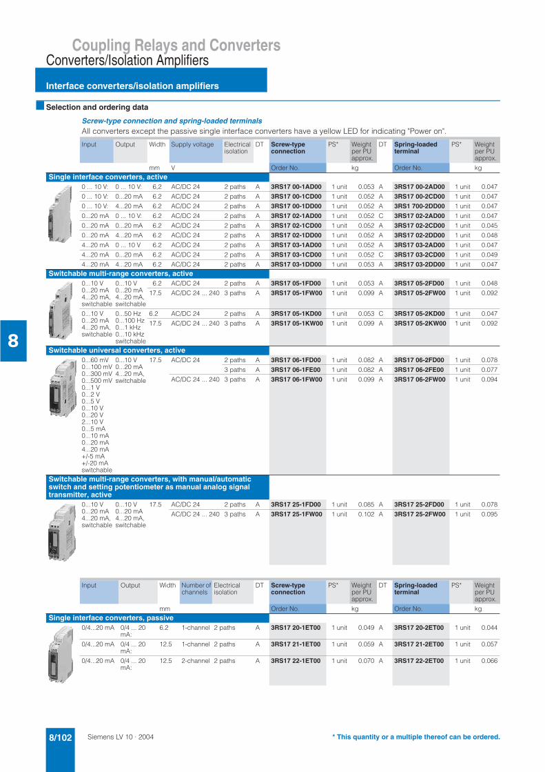
Siemens LV 10 · 20048/102
Coupling Relays and Converters
Interface converters/isolation amplifiers
Converters/Isolation Amplifiers
8
Selection and ordering data
Screw-type connection and spring-loaded terminalsAll converters except the passive single interface converters have a yellow LED for indicating "Power on".
Input Output Width Supply voltage Electrical isolation
DT Screw-type connection
PS* Weight per PU approx.
DT Spring-loadedterminal
PS* Weight per PU approx.
mm V Order No. kg Order No. kgSingle interface converters, active
0 ... 10 V: 0 ... 10 V: 6,2 AC/DC 24 2 paths A 3RS17 00-1AD00 1 unit 0.053 A 3RS17 00-2AD00 1 unit 0.047
0 ... 10 V: 0...20 mA 6.2 AC/DC 24 2 paths A 3RS17 00-1CD00 1 unit 0.052 A 3RS17 00-2CD00 1 unit 0.047
0 ... 10 V: 4...20 mA 6.2 AC/DC 24 2 paths A 3RS17 00-1DD00 1 unit 0.052 A 3RS1 700-2DD00 1 unit 0.047
0...20 mA 0 ... 10 V: 6.2 AC/DC 24 2 paths A 3RS17 02-1AD00 1 unit 0.052 C 3RS17 02-2AD00 1 unit 0.047
0...20 mA 0...20 mA 6.2 AC/DC 24 2 paths A 3RS17 02-1CD00 1 unit 0.052 A 3RS17 02-2CD00 1 unit 0.045
0...20 mA 4...20 mA 6.2 AC/DC 24 2 paths A 3RS17 02-1DD00 1 unit 0.052 A 3RS17 02-2DD00 1 unit 0.048
4...20 mA 0 ... 10 V 6.2 AC/DC 24 2 paths A 3RS17 03-1AD00 1 unit 0.052 A 3RS17 03-2AD00 1 unit 0.047
4...20 mA 0...20 mA 6.2 AC/DC 24 2 paths A 3RS17 03-1CD00 1 unit 0.052 C 3RS17 03-2CD00 1 unit 0.049
4...20 mA 4...20 mA 6.2 AC/DC 24 2 paths A 3RS17 03-1DD00 1 unit 0.053 A 3RS17 03-2DD00 1 unit 0.047Switchable multi-range converters, active
0...10 V0...20 mA4...20 mA, switchable
0...10 V0...20 mA4...20 mA, switchable
6.2 AC/DC 24 2 paths A 3RS17 05-1FD00 1 unit 0.053 A 3RS17 05-2FD00 1 unit 0.048
17.5 AC/DC 24 ... 240 3 paths A 3RS17 05-1FW00 1 unit 0.099 A 3RS17 05-2FW00 1 unit 0.092
0...10 V0...20 mA4...20 mA, switchable
0...50 Hz0...100 Hz0...1 kHz0...10 kHzswitchable
6.2 AC/DC 24 2 paths A 3RS17 05-1KD00 1 unit 0.053 C 3RS17 05-2KD00 1 unit 0.047
17.5 AC/DC 24 ... 240 3 paths A 3RS17 05-1KW00 1 unit 0.099 A 3RS17 05-2KW00 1 unit 0.092
Switchable universal converters, active0...60 mV0...100 mV0...300 mV0...500 mV0...1 V0...2 V0...5 V0...10 V0...20 V2...10 V0...5 mA0...10 mA0...20 mA4...20 mA+/-5 mA+/-20 mAswitchable
0...10 V0...20 mA4...20 mA, switchable
17.5 AC/DC 24 2 paths A 3RS17 06-1FD00 1 unit 0.082 A 3RS17 06-2FD00 1 unit 0.078
3 paths A 3RS17 06-1FE00 1 unit 0.082 A 3RS17 06-2FE00 1 unit 0.077
AC/DC 24 ... 240 3 paths A 3RS17 06-1FW00 1 unit 0.099 A 3RS17 06-2FW00 1 unit 0.094
Switchable multi-range converters, with manual/automatic switch and setting potentiometer as manual analog signal transmitter, active
0...10 V0...20 mA4...20 mA, switchable
0...10 V0...20 mA4...20 mA, switchable
17.5 AC/DC 24 2 paths A 3RS17 25-1FD00 1 unit 0.085 A 3RS17 25-2FD00 1 unit 0.078
AC/DC 24 ... 240 3 paths A 3RS17 25-1FW00 1 unit 0.102 A 3RS17 25-2FW00 1 unit 0.095
Input Output Width Number of channels
Electricalisolation
DT Screw-type connection
PS* Weight per PU approx.
DT Spring-loadedterminal
PS* Weight per PU approx.
mm Order No. kg Order No. kgSingle interface converters, passive
0/4...20 mA 0/4 ... 20 mA:
6.2 1-channel 2 paths A 3RS17 20-1ET00 1 unit 0.049 A 3RS17 20-2ET00 1 unit 0.044
0/4...20 mA 0/4 ... 20 mA:
12.5 1-channel 2 paths A 3RS17 21-1ET00 1 unit 0.059 A 3RS17 21-2ET00 1 unit 0.057
0/4...20 mA 0/4 ... 20 mA:
12.5 2-channel 2 paths A 3RS17 22-1ET00 1 unit 0.070 A 3RS17 22-2ET00 1 unit 0.066
* This quantity or a multiple thereof can be ordered.
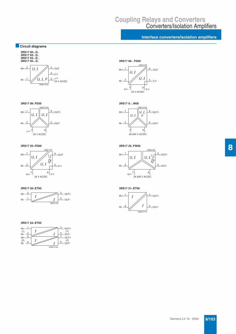
Siemens LV 10 · 2004 8/103
Coupling Relays and ConvertersConverters/Isolation Amplifiers
Interface converters/isolation amplifiers
8
Circuit diagrams
3RS17 00-..D.. 3RS17 02-..D.. 3RS17 03-..D. .3RS17 05-..D.. 3RS17 06- . FD00
3RS17 06-.FE00 3RS17 0.-..W00
3RS17 25-.FD00 3RS17 25-.FW00
3RS17 20-.ET00 3RS17 21-.ET00
3RS17 22-.ET00
!* $+,
-%
!.
- */0
!* $+,
1
!.
1
-
2*/
0
!* $+,*
2%
!.
1
-$+,.
2*/
0
!* $+,*
3%
!.
1
-$+,.
2
.0
!* $+,
!.
1
-
2*/
0
!* $+,*
-
!.
1
-$+,.
2*/
.0
!*
!.
$+,*
$+,.
!* $+,*
%
!.
$+,.
-
1
1%
!*
!.
!*
!.
$+,*
$+,.
$+,*
2$+,.
45
4545
45
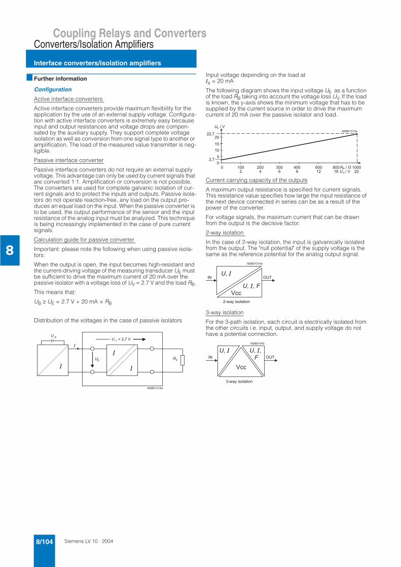
Siemens LV 10 · 20048/104
Coupling Relays and Converters
Interface converters/isolation amplifiers
Converters/Isolation Amplifiers
8
Further information
Configuration
Active interface converters
Active interface converters provide maximum flexibility for the application by the use of an external supply voltage. Configura-tion with active interface converters is extremely easy because input and output resistances and voltage drops are compen-sated by the auxiliary supply. They support complete voltage isolation as well as conversion from one signal type to another or amplification. The load of the measured value transmitter is neg-ligible.
Passive interface converter
Passive interface converters do not require an external supply voltage. This advantage can only be used by current signals that are converted 1:1. Amplification or conversion is not possible. The converters are used for complete galvanic isolation of cur-rent signals and to protect the inputs and outputs. Passive isola-tors do not operate reaction-free, any load on the output pro-duces an equal load on the input. When the passive converter is to be used, the output performance of the sensor and the input resistance of the analog input must be analyzed. This technique is being increasingly implemented in the case of pure current signals.
Calculation guide for passive converter
Important: please note the following when using passive isola-tors:
When the output is open, the input becomes high-resistant and the current-driving voltage of the measuring transducer UE must be sufficient to drive the maximum current of 20 mA over the passive isolator with a voltage loss of UV = 2.7 V and the load RB.
This means that:
UB ≥ UE = 2.7 V + 20 mA × RB
Distribution of the voltages in the case of passive isolators
Input voltage depending on the load at Ia = 20 mA
The following diagram shows the input voltage UE as a function of the load RB taking into account the voltage loss UV. If the load is known, the y-axis shows the minimum voltage that has to be supplied by the current source in order to drive the maximum current of 20 mA over the passive isolator and load.
Current carrying capacity of the outputs
A maximum output resistance is specified for current signals. This resistance value specifies how large the input resistance of the next device connected in series can be as a result of the power of the converter.
For voltage signals, the maximum current that can be drawn from the output is the decisive factor.
2-way isolation
In the case of 2-way isolation, the input is galvanically isolated from the output. The "null potential" of the supply voltage is the same as the reference potential for the analog output signal.
3-way isolation
For the 3-path isolation, each circuit is electrically isolated from the other circuits i.e. input, output, and supply voltage do not have a potential connection.
4
( < 3 % (
3 %
; ( ;
4 ; (
3 %
! $+,
%
.&%6 )%
! $+,
.&%6 )%
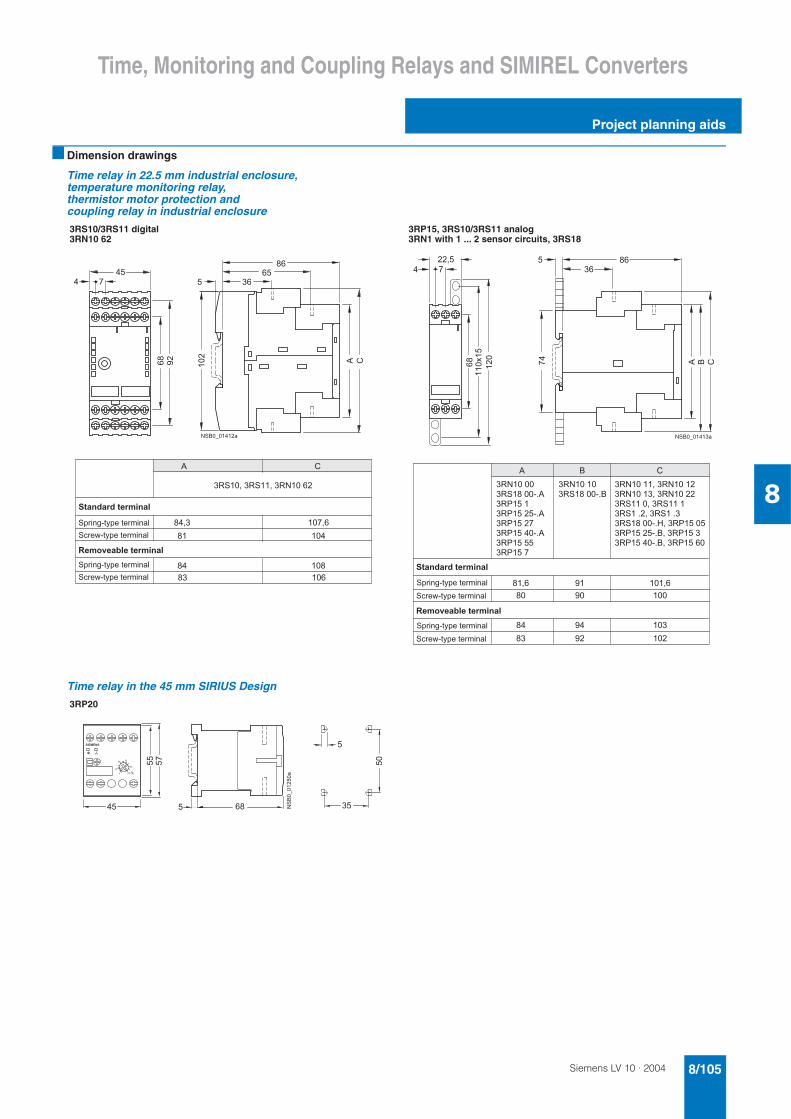
Siemens LV 10 · 2004 8/105
Time, Monitoring and Coupling Relays and SIMIREL Converters
Project planning aids
8
Dimension drawings
Time relay in 22.5 mm industrial enclosure, temperature monitoring relay, thermistor motor protection and coupling relay in industrial enclosure
Time relay in the 45 mm SIRIUS Design
3RS10/3RS11 digital3RN10 62
3RP15, 3RS10/3RS11 analog3RN1 with 1 ... 2 sensor circuits, 3RS18
!
!
"
#
$
$ #
$
$ #
$
$
#
# #
# % $
$ # $
$ # $
!
!
3RP20
&

Siemens LV 10 · 20048/106
Time, Monitoring and Coupling Relays and SIMIREL Converters
Project planning aids
8
Time relays for mounting onto the front panel
Time relays for mounting onto contactors
7PV33 7PV41/7PV43
Accessories: LZX socket: MR78750 for7PV33; 7PV4
Accessories:7PX9921 socket with rear connection
1--
-
2
2
-*1
-
*
1
%
"%' ))- 7%##
8%9"%# (
7) ()&-
-
2
2
-
1
2
3
2
2%
2-
-%:
7%##
& 3
3
3
3
-
%
3RT19 16-2E, -2F, -2G, -2L ...Solid-state time-delay auxiliary switch blocks
3RT19 26-2E, -2F, -2G ...
for size S00 contactors and auxiliary contactors
for size S0 to S3 contactors and auxiliary contactors
3RT19 16-2C ... Solid-state time-delay blocks with ON-delay
3RT19 26-2C ...
for mounting onto the front of contactors for size S00
for mounting at the top or bottom of the contactors for sizes S0 to S3
3
2-
2
- 3
-
-
2
3
21
-
-
1
1
3
2
2-
2
11
3
22
-1
-

Siemens LV 10 · 2004 8/107
Time, Monitoring and Coupling Relays and SIMIREL Converters
Project planning aids
8
Time relays for mounting onto contactors
Monitoring relays
Sensors for level monitoring
3RT19 16-2D ... solid-state time-delay blocks, OFF-delay 3RT19 26-2D ...
for mounting onto the front of size S00 contactors
for mounting at the top or bottom of the contactors for sizes S0 to S3
3
23
1
2
23 --
-1
-
1
3
3
3UG30 3UG35 (without 3UG35 11) 3UG35 11
3
2
3
-
3
- -
3
2
3
-
3
- 1
3-
2 -
3UG32 07-3A Three-pole wire electrode
3UG32 07-2ATwo-pole wire electrode
3UG32 07-2B Two-pole bow electrode
3UG32 07-1BSingle-pole bow electrode
3UG32 07-1C Single-pole electrode, rugged design
-
-
;
-
-
3
3
%
-
-
;
-
-
3
3
--
<1<
-
;
- 33%
--
<1<
-
;
33
-
-
;
-
33-
7,8. )#%

Siemens LV 10 · 20048/108
Time, Monitoring and Coupling Relays and SIMIREL Converters
Project planning aids
8
Coupling relays with narrow type of construction
1) Dimensions for 3TX7 004 coupling links (screw-type connections).
2) Dimensions for 3TX7 005 coupling links (spring-loaded terminals).
3TX7 002, 3TX7 003 coupling links in terminal block design
3TX7 00 .-1AB . ., 3TX7 00 .-2A . . ., 3TX7 002-3AB01
3TX7 002-3AB00, 3TX7 002-4A . . .
3TX7 00 .-1BB00, 3TX7 00 .-1BF00, 3TX7 002-2BF02
3TX7 00 .-1CB00, 3TX7 002-1BF02
3TX7 004, 3TX7 005 coupling links in two-tier design
Relay coupling links3TX7 00 .-1MB00, 3TX7 00 .-1MF00, 3TX7 00 .-1L . 0 ., 3TX7 00 .-2M . . .
Relay coupling links3TX7 00 .-1AB10, 3TX7 00 .-1BB00, 3TX7 00 .-1BB10, 3TX7 00 .-1CB00, 3TX7 00 .-1BF05
Relay coupling links3TX7 00 .-1HB00
Relay coupling links3TX7 00 .-1GB00
Semiconductor coupling links3TX7 00 .-3AB04, 3TX7 00 .-4AB04, 3TX7 00 .-3PB . ., 3TX7 00 .-3PG74, 3TX7 00 .-3RB43, 3TX7 00 .-4P . 24
Semiconductor coupling links3TX7 00 .-3AC04, 3TX7 00 .-3AC14, 3TX7 00 .-3AC03
3TX7 014
-
=
12
2
-
=
-
=
13
=1-
1
1
-
-
2
3
5
2
5
-
'

Siemens LV 10 · 2004 8/109
Time, Monitoring and Coupling Relays and SIMIREL Converters
Project planning aids
8
Plug-in relays
LZX:RT3/RT4 complete unit LZX:RT3/RT4 print relay LZX:RT78625 socketfor print relay
LZX:RT78626 socket with safe isolation for print relay
LZX:PT570 industrial relay LZX:PT270 industrial relay LZX:PT78704 socket for industrial relay
LZX:MT32 industrial relay LZX:MT78750 socket for industrial relay
!
"
"
"
!
!
!
!
"
"
#
!
& 3
3
3
3

Siemens LV 10 · 20048/110
Time, Monitoring and Coupling Relays and SIMIREL Converters
Project planning aids
8
Power relays
Converter/isolation amplifiers
1) Width for 3RS17 25 is approx. 90 mm.
2) Dimensions for screw-type connection.
3) Dimensions for spring-loaded terminal.
4) Can be snapped onto 35 mm standard mounting rail.
AC and DC operation Accessories for 3TG10
3TG10 ..-0.. with screw-type connections
3TG10 ..-1.. with tab connectors
Parallel connections, 4-pole, with 3RT19 16-4BB41 connection terminal
The parallel connections can be reduced by one pole.
3RS17
6.2 mm type of construction 12.5 mm type of construction 17.5 mm type of construction
7