simocrane drive-based technology · management system advanced technology motors basic technology...
TRANSCRIPT

SIMOCRANEDrive-Based TechnologyV1.0 SP2 HF1Description and Tutorial

© Siemens AG 2018June 2018Page 2 Siemens Cranes
SIM
OC
RA
NE
Motion Controller
Drive Controller
Drives
Pla
tfo
rm
CraneTechnology
CraneManagementSystemAdvancedTechnology
Motors
BasicTechnology
Sway Control
Skew Control
2D-Trajectory
Book-sizeChassis
CraneCabinetModules
Basic Technology
SIMOTION D435-2
ECO Technology
Truck Position System
(Remote) CMS CMS Lean
Drive-Based Technology
CU310-2
PM340/PM Chassis
PM250
Mid PerformanceHigh Performance
Drive-Based Sway Control
PM240-2(FSA-FSG)
AdvancedCUD
CU320-2
DCM
V1.0 SP2V1.0 SP2 HF1
SIMOCRANE Product Portfolio
1PH81LP11LQ11LM1
1PC1DC-Motor 1LE1

© Siemens AG 2018June 2018Page 3 Siemens Cranes
Control Units
AC/AC drives
SIMOCRANE Drive-Based Technology V1.0 SP2 HF1on base of SINAMICS FW V5.1 standard
PM340/PM Chassis
PM240-2(FSA-FSG)
Single-axis SolutionPackage:6GA7270-1AA20-0AA0
Control Units
DC/AC drives
Book-sizeChassisCrane CabinetModules
- CU320-2- CU310-2
Multi-axis SolutionPackage:6GA7270-1AA20-0AA0
PM250

© Siemens AG 2018June 2018Page 4 Siemens Cranes
Control Units
AC/AC drives
SIMOCRANE Drive-Based Technology V1.0 SP1 HF2on base of SINAMICS FW V4.7 HF11 Cranes
PM340/PM Chassis
PM250 PM240-2(FSA-FSC)
Single-axis Solution
Package:6GA7270-1AA11-0AA0
- CU310-2

© Siemens AG 2017 siemens.com/answers
Product Introduction

© Siemens AG 2018June 2018Page 6 Siemens Cranes
Functional Scope DBT V1.0 SP2 HF1 (part 1)
ƒ Crane midrange solution is⋅ A drive-based solution in SINAMICS S120 environment⋅ For both Single-axis (CU310-2) and Multi-axis (CU320-2) solution,⋅ Standard SINAMICS Firmware V5.1⋅Crane specialized technologies in DCC-blocks
• SINAMICS FW V5.1 can operate⋅With PM340 and PM Chassis⋅With PM240-2 (Frame size A – Frame size G)⋅With Motor Module and cabinet modules⋅ But not with PM250
ƒ Crane technology in DCC-Blocks• Load-dependent field weakening• Pre-limit switch (selectable limiting)• Start pulse• Master switch• Over-speed monitoring (not a fail-safe function)• Current distribution monitoring (for double Axes)
Drive Control Chart

© Siemens AG 2018June 2018Page 7 Siemens Cranes
Functional Scope DBT V1.0 SP2 HF1 (part 2)
ƒ Standard application for Single-axis via I/O-onboard or via Profibus• Selectable via I/O-onboard or via Profibus• Selectable with analogue or digital master-switch• Selectable for Hoist/Trolley/Gantry• Combination of Startpulse with brake control• Configuration via scripting
⋅ Standard application for multi-axis via ProfiNetƒ for Hoist, Trolley and Gantryƒ Communication via ProfiNetƒ application for Master-Slave torque controlƒ Configuration via scripting
ƒ The Crane DCC-chart is know-how protected, therefore, it can not be opened. The customizedDCC application can be made in another DCC-chart under other Drive-Object (e.g. CU).
ƒ The grab function and synchronous operation are not parts of this product.

© Siemens AG 2018June 2018Page 8 Siemens Cranes
Scope of Delivery
⋅ Memory card (CF card)• SINAMICS FW V5.1 (Standard)
⋅ CD with• Cranes DCC blocks• Standard applications• Documentation
Package for DBT V1.0 SP2 HF1Order number: 6GA7270-1AA20-0AA0

© Siemens AG 2018June 2018Page 9 Siemens Cranes
SIMOCRANE Drive-Based TechnologyOperation Manuals and Application note

© Siemens AG 2018June 2018Page 10 Siemens Cranes
⋅ Video Downloadhttps://w3.siemens.com/mcms/mc-solutions/de/maschinenbau/kranloesungen/video/Seiten/krane-videos.aspx
⋅ Training Course in SiTrain-NL
⋅ Training slides – Description and Tutorial
SIMOCRANE Drive-Based TechnologyTraining Possibilities

© Siemens AG 2018June 2018Page 11 Siemens Cranes
ƒ For training of commissioning⋅ with BOP 20
⋅ with Starter
⋅ with Sinamics web server
ƒ For test of customized adaptation
ƒ For customer presentation
ƒ Components⋅ PM340 * 1AC 230V
⋅ Asynchronmotor 1LA7060 -4.. with/without encoder
⋅ CU310-2 DP with BOP 20 ⇓ CU310-2 PN
⋅ Emergency Stop Pushbutton (Safety integrated function)
⋅ Switches hard-wired to CU310-2 DP⇓ CU310-2 PN
SIMOCRANE Drive-Based TechnologyDemo-kit

© Siemens AG 2017 siemens.com/answers
Application examples

© Siemens AG 2018June 2018Page 13 Siemens Cranes
Use Case 1Simple OHBC with hanging key button

© Siemens AG 2018June 2018Page 14 Siemens Cranes
SIMOCRANE Drive-Based TechnologyReady to Apply Solution on CU310-2 DP
⋅ Standard application for Single-axis Controlled via onboard-I/O Digital Master-switch up to 4 speed-levels Combination of Startpulse with brake control With encoder
⋅ Start commissioning after few steps in engineering and crane installation
⋅ Simple commissioning via onboard Basic Operator Panel BOP20
⋅ Optional commissioning via SINAMICS web server on PC or Tablet

© Siemens AG 2018June 2018Page 15 Siemens Cranes
Configuration Example for Use Case 1 (single-axis)OHBC with Onboard I/O- Signals
Hoist
SINAMICSCU310-2
SINAMICS
CU310-2SINAMICSCU310-2
Meisterschalter
Cross travel Long travel

© Siemens AG 2018June 2018Page 16 Siemens Cranes
Use Case 2OHBC crane with remote control
Waste incineration plant crane
© Siemens AG 2018June 2018Page 17 Siemens Cranes
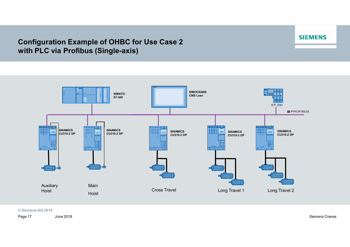
Configuration Example of OHBC for Use Case 2with PLC via Profibus (Single-axis)
SINAMICSCU310-2 DP
SINAMICSCU310-2 DP
SINAMICSCU310-2 DP
SINAMICSCU310-2 DP
SIMOCRANECMS LeanSIMATIC
S7-300
Main
Hoist
AuxiliaryHoist Cross Travel Long Travel 1
SINAMICSCU310-2 DP
Long Travel 2

© Siemens AG 2018June 2018Page 18 Siemens Cranes
SIMOCRANE Drive-Based TechnologyReady to Apply Solution for Multi-axis
Pre-configuring via script
Application note for multi-axis

© Siemens AG 2018June 2018Page 19 Siemens Cranes
Configuration Example for Use Case 2OHBC with PLC via Profinet RT (Multi-axis)
1 1SIMATICS7-300
1 1
Hoist Trolley Gantry 1 Gantry 2
Common DC-Bus
CU320-2 PN
1

© Siemens AG 2018June 2018Page 20 Siemens Cranes
⋅ Product News about Delivery release (including slides)
It will be soon published
⋅ Operation instructionhttps://support.industry.siemens.com/cs/de/en/view/109747425
⋅ Flyerhttp://w3app.siemens.com/mcms/infocenter/content/en/Pages/order_form.aspx?nodeKey=key_9180778&infotype=brochures
⋅ Catalogue CR 1http://w3app.siemens.com/mcms/infocenter/dokumentencenter/mc/Documentsu20Catalogs/CR1-2015-en.pdf
Product Support forSIMOCRANE Drive-Based Technology

© Siemens AG 2018June 2018Page 21 Siemens Cranes
SIMOCRANE Product Support⋅ SIMOCRANE Product-Support (news, FAQs, Manuals, application note..) in Internethttps://support.industry.siemens.com/cs/ww/de/ps/20087
⋅ SIMOCRANE Traininghttp://www.corporate.siemens.nl/nl/siemens-in-nederland/ons-portfolio/cross-sector-services/siemens-training/cranes.htm
⋅ Support request via Internet (Product ⇓ Simocrane)http://support.automation.siemens.com
⋅ Hotline EUROPA– Telefon: +49 (0) 911 895 7 222
– Fax: +49 (0) 911 895 7 223
– Email: [email protected]
⋅ Hotline AMERICA– Telefon: +1 423 262 5710
– Fax: +1 423 262 2231
– Email: [email protected]
⋅ Hotline ASIA / PACIFIC– Telefon: +86 10 6475 7575
– Fax: +86 10 6474 7474
– Email: [email protected]

© Siemens AG 2017 siemens.com/answers
Commissioning Guideline

© Siemens AG 2018June 2018Page 23 Siemens Cranes
SIMOCRANE Drive-Based TechnologyOverview of Commissioning Guideline
Import Standard project
Run Script file
Commissioning Drive
Parametrizing DBT
Compile and download
SIMOCRANE (Chapter 6)
SINAMICS (Getting Started)
Configurate DO
Adobe AcrobatDocumentStart
Step 1
Step 2
Step 3
Step 4
Step 5
Step 6
© Siemens AG 2018June 2018Page 24 Siemens Cranes
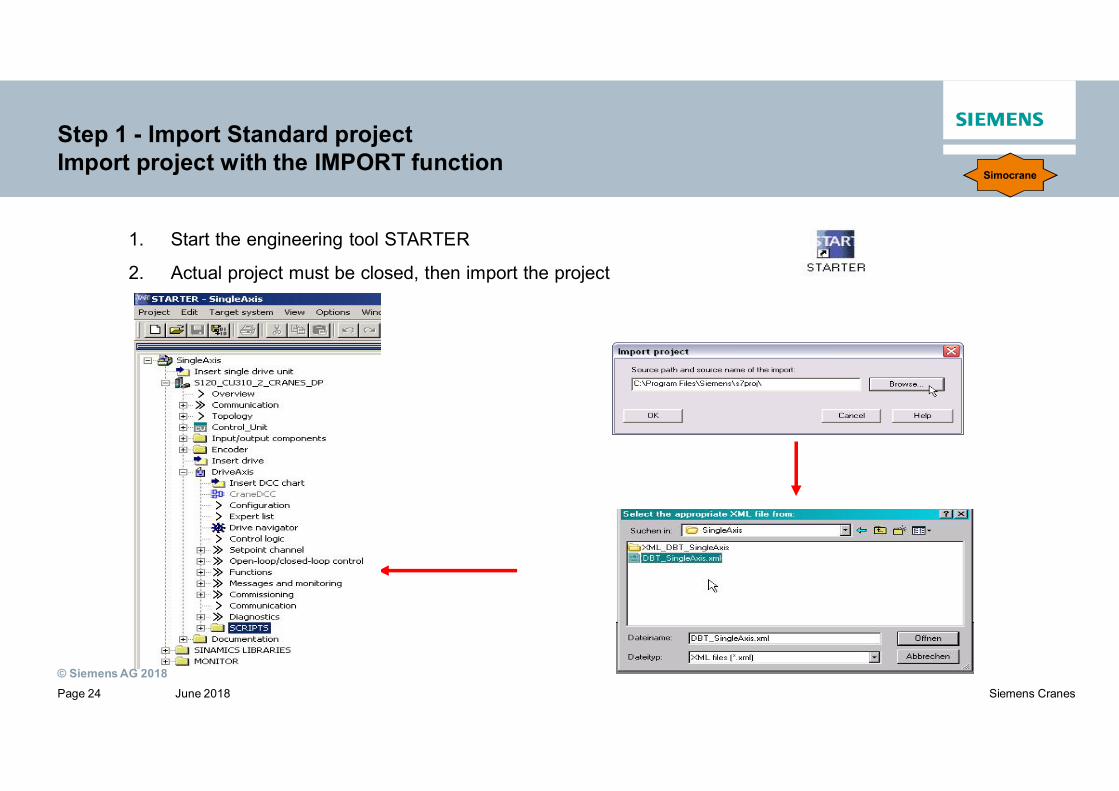
Step 1 - Import Standard projectImport project with the IMPORT function
1. Start the engineering tool STARTER
2. Actual project must be closed, then import the project
Simocrane

© Siemens AG 2018June 2018Page 25 Siemens Cranes
Step 2 - Configurate DOConfiguration of the Drive Object (DO)
Sinamics

© Siemens AG 2018June 2018Page 26 Siemens Cranes
Step 2 - Configurate DOSelect control method
Sinamics

© Siemens AG 2018June 2018Page 27 Siemens Cranes
Step 2 - Configurate DOConfiguring of the power unit and drive properties
Sinamics

© Siemens AG 2018June 2018Page 28 Siemens Cranes
Step 2 - Configurate DOConfiguring of motor Sinamics
© Siemens AG 2018June 2018Page 29 Siemens Cranes
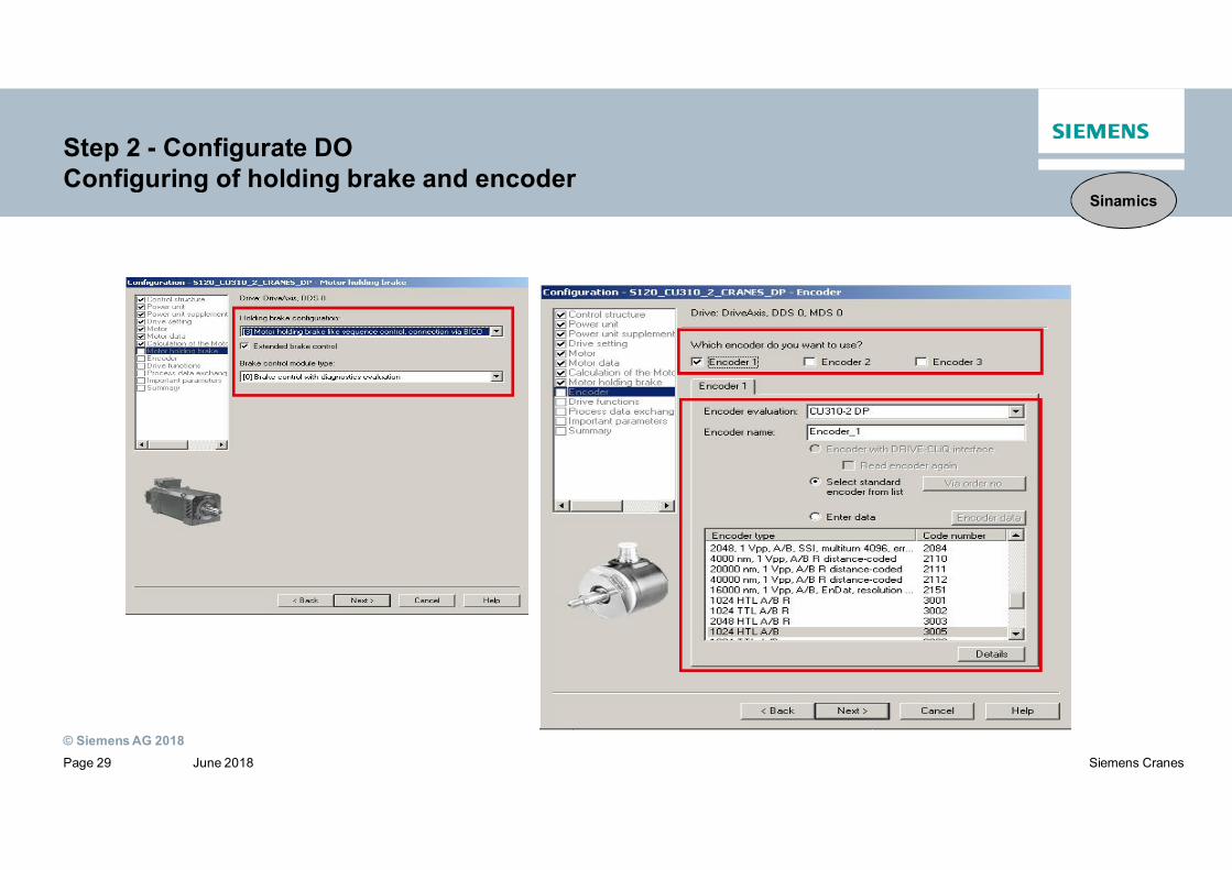
Step 2 - Configurate DOConfiguring of holding brake and encoder
Sinamics
© Siemens AG 2018June 2018Page 30 Siemens Cranes
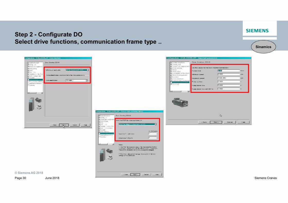
Step 2 - Configurate DOSelect drive functions, communication frame type ..
Sinamics

© Siemens AG 2018June 2018Page 31 Siemens Cranes
Step 2 - Configurate DOSummary
Sinamics

© Siemens AG 2018June 2018Page 32 Siemens Cranes
Step 2 - Configurate DOCheck Topology
Sinamics

© Siemens AG 2018June 2018Page 33 Siemens Cranes
Step 3 - Run Script fileExecute Script file
Simocrane

© Siemens AG 2018June 2018Page 34 Siemens Cranes
Step 3 - Run Script fileScript file window
Simocrane
© Siemens AG 2018June 2018Page 35 Siemens Cranes
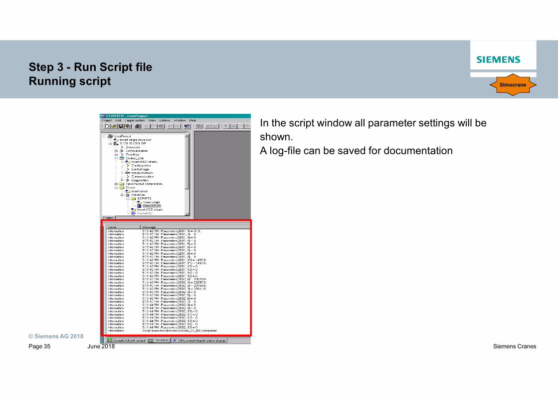
Step 3 - Run Script fileRunning script
In the script window all parameter settings will beshown.A log-file can be saved for documentation
Simocrane

© Siemens AG 2018June 2018Page 36 Siemens Cranes
Step 3 - Run Script fileSetpoint channel in CU310-2 after running script (via Profibus control)
Simocrane
© Siemens AG 2018June 2018Page 37 Siemens Cranes
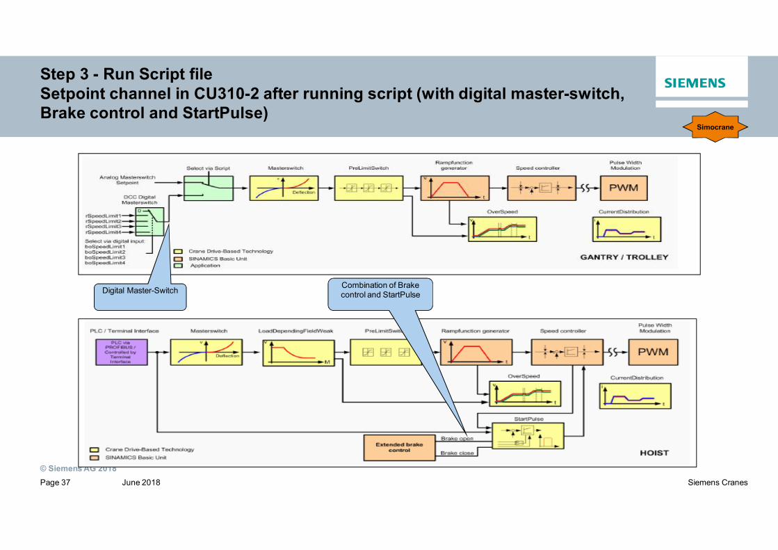
Step 3 - Run Script fileSetpoint channel in CU310-2 after running script (with digital master-switch,Brake control and StartPulse)
Combination of Brakecontrol and StartPulseDigital Master-Switch
Simocrane

© Siemens AG 2018June 2018Page 38 Siemens Cranes
Step 4 - Compile and downloadDownload into CF-card
Save and compile the project and then the projectcan be downloaded in two ways:
1. With STARTER go online via Profibus toSINAMICS CU310-2 and download theproject into the device.
2. Put the Compact Flash card into a card reader and download theproject direct to the CF card and then put the CF card into the device.
Sinamics

© Siemens AG 2018June 2018Page 39 Siemens Cranes
Step 4 - Compile and downloadCommunication Interface via Profibus
For online download the profibus address must be configured as follows:
Sinamics

© Siemens AG 2018June 2018Page 40 Siemens Cranes
Step 4 - Compile and downloadCommunication Interface via Profibus
ƒThe profibus address is entered here. (This must correspond to the profibusaddress found on the CU310-2)
ƒThe profibus address can be set on the CU310-2 by setting the switches foundunderneath the BOP.
Sinamics

© Siemens AG 2018June 2018Page 41 Siemens Cranes
Step 4 - Compile and downloadCommunication interface via Ethernet (1)
ƒFor using an Ethernet connection to connect to the control unit select theaccessible nodes button to find device.
Sinamics

© Siemens AG 2018June 2018Page 42 Siemens Cranes
Step 4 - Compile and downloadCommunication interface via Ethernet (2)
ƒIf the device is not found immediately:1. Set access point to device in the accessible nodes tab.
Sinamics

© Siemens AG 2018June 2018Page 43 Siemens Cranes
Step 4 - Compile and downloadCommunication interface via Ethernet (3)
2. Set the PG/PC interface in the accessible nodes tab. (Tip: Selectcomponent which has <Active> written after it).
Sinamics

© Siemens AG 2018June 2018Page 44 Siemens Cranes
Step 4 - Compile and downloadCommunication interface via Ethernet (4)
3. Select search for accessible nodes again.4. When the device is found note the IP address.
Sinamics

© Siemens AG 2018June 2018Page 45 Siemens Cranes
Step 4 - Compile and downloadCommunication interface via Ethernet (5)
5.Adjust the PG/PC IP address so that it will have the same first 3 numbers asthe address of the device but with a different fourth number. (E. g. If the deviceaddress is 169.254.11.22 then the PC/PG address should be changedaccordingly to an address with the same first 3 numbers but a different fourth e.g. 169.254.11.1)6.Highlight device in accessible nodes tab and accept device into project.
Sinamics

© Siemens AG 2018June 2018Page 46 Siemens Cranes
Step 5 - Commissioning DriveOverview of drive navigator
Sinamics

© Siemens AG 2018June 2018Page 47 Siemens Cranes
Step 5 - Commissioning DriveOverview of I/O-Signals
Analogue
Digital
Sinamics

© Siemens AG 2018June 2018Page 48 Siemens Cranes
Step 5 - Commissioning DriveOverview of parameter list
Sinamics

© Siemens AG 2018June 2018Page 49 Siemens Cranes
Step 5 - Commissioning DriveMainstream of speed setpoint and closed-loop control
Speed controller Torque setpoints Torque limiting
DRIVE-CLiQ
Current setpoint filter Current controller Power unit
Ramp function generator
Setpoint filter+precontrol
Speed setpoint
M
Sinamics

© Siemens AG 2018June 2018Page 50 Siemens Cranes
Step 5 - Commissioning DriveSpeed setpoint
Sinamics

© Siemens AG 2018June 2018Page 51 Siemens Cranes
Step 5 - Commissioning DriveRamp-function generator
Sinamics

© Siemens AG 2018June 2018Page 52 Siemens Cranes
Step 5 - Commissioning DriveRamp-function generator
Simple ramp-functiongenerator
Extended ramp-function generator
Sinamics

© Siemens AG 2018June 2018Page 53 Siemens Cranes
Step 5 - Commissioning DriveSpeed controller
Sinamics

© Siemens AG 2018June 2018Page 54 Siemens Cranes
Step 5 - Commissioning DriveUpper and Lower Torque Limit
Sinamics
© Siemens AG 2018June 2018Page 55 Siemens Cranes
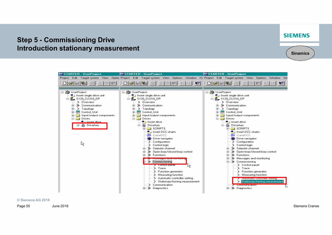
Step 5 - Commissioning DriveIntroduction stationary measurement
Sinamics
© Siemens AG 2018June 2018Page 56 Siemens Cranes
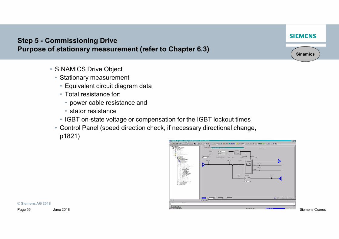
Step 5 - Commissioning DrivePurpose of stationary measurement (refer to Chapter 6.3)
• SINAMICS Drive Object• Stationary measurement
• Equivalent circuit diagram data• Total resistance for:
• power cable resistance and• stator resistance
• IGBT on-state voltage or compensation for the IGBT lockout times• Control Panel (speed direction check, if necessary directional change,
p1821)
Sinamics

© Siemens AG 2018June 2018Page 57 Siemens Cranes
Step 5 - Commissioning DriveStart stationary measurement
1.Select stationery measurement from the drop down menu.2.Activate measurement.
Sinamics

© Siemens AG 2018June 2018Page 58 Siemens Cranes
Step 5 - Commissioning DriveResults of the stationary measurement
Sinamics
© Siemens AG 2018June 2018Page 59 Siemens Cranes
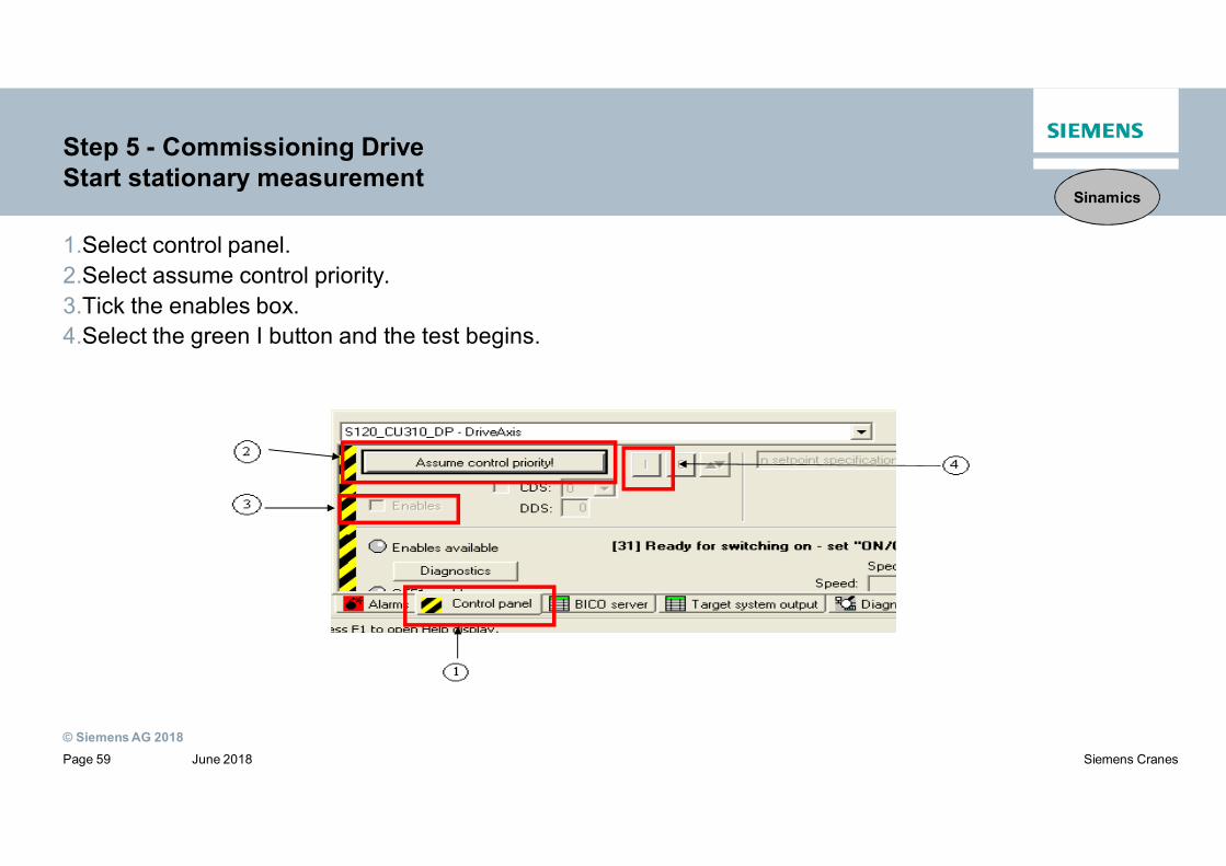
Step 5 - Commissioning DriveStart stationary measurement
1.Select control panel.2.Select assume control priority.3.Tick the enables box.4.Select the green I button and the test begins.
Sinamics

© Siemens AG 2018June 2018Page 60 Siemens Cranes
Step 5 - Commissioning DrivePurpose of rotating measurement (refer to Chapter 6.3)
• SINAMICS Drive Object• Rotating Measurement and Speed Controller Optimization
• Measurement of magnetization characteristic• Measurement of magnetization current• Speed controller optimization• Acceleration pre-control setting• Setting for ratio between the total moment of inertia and that for the
motor
Sinamics

© Siemens AG 2018June 2018Page 61 Siemens Cranes
Step 5 - Commissioning DriveStart turning measurement
1.After stationery measurement select deactivate measurement.2.Then select next measurement.ƒRepeat steps taken for stationery except select turning measurement withencoder from the drop down menu,
Sinamics

© Siemens AG 2018June 2018Page 62 Siemens Cranes
Step 5 - Commissioning DriveErrors in rotating measurement
ƒIf errors occur in rotating measurement test make sure that all steps have beenfollowed correctly.ƒCheck drive diagnostics in control panel.
Sinamics

© Siemens AG 2018June 2018Page 63 Siemens Cranes
Step 5 - Commissioning DriveErrors in rotating measurement
ƒUse alarm screen and click on error message for help to troubleshoot fault.
ƒTo attempt rotating test again make sure to acknowledge errors in alarmsscreen.
Sinamics

© Siemens AG 2018June 2018Page 64 Siemens Cranes
Step 5 - Commissioning DriveResults of the rotating measurement
Sinamics
© Siemens AG 2018June 2018Page 65 Siemens Cranes
Step 6 - Parametrizing DBTAlternative to rotating measurement (refer to Chapter 6.3)
If the rotating measurement cannot be performed, it is possible to correct manually themissed rotating measurement settings:
- To correct manually the magnetizing current and magnetizinginductance
- Speed control optimization by re-calculating the controlparameters (p0340) or by optimizing manually the controller
Refer to the manual “SIMOCRANE Drive-Based Technology”, Chapter 6.3
Simocrane

© Siemens AG 2018June 2018Page 66 Siemens Cranes
Step 6 - Parametrizing DBTOpen the Expert list
Select DriveAxis with the rightmouse, a new window will beopened.
Select Expert and Expert list
Simocrane

© Siemens AG 2018June 2018Page 67 Siemens Cranes
Step 6 - Parametrizing DBTDCC Parameters in the Expert list
Simocrane

© Siemens AG 2018June 2018Page 68 Siemens Cranes
Step 6 - Parametrizing DBTDCC_MasterSwitch (refer to Chapter 4.2)
In order that for low deflection angles lower speed setpoints are obtained than those that correspond linearly to thedeflection angle, the master switch setpoint is modeled through a non-linear function. This allows the drive to beprecisely positioned in the manual mode.
Simocrane

© Siemens AG 2018June 2018Page 69 Siemens Cranes
Step 6 - Parametrizing DBTDCC_DigitalMasterSwitch (refer to Chapter 7.1.1)
Simocrane
DI0
DI0
+D
I2
P. Speed 1
P. Speed 4
P. Speed 2
Digtal Input
P. Speed 3
N. Speed 4
N. Speed 1
N. Speed 3N. Speed 2
Speed
DI0
+D
I2+
DI3
DI0
+D
I2+
DI3
+D
I8
DI1
+D
I2
DI1
+D
I2+
DI3
DI1
+D
I2+
DI3
+D
I8
DI1
© Siemens AG 2018June 2018Page 70 Siemens Cranes
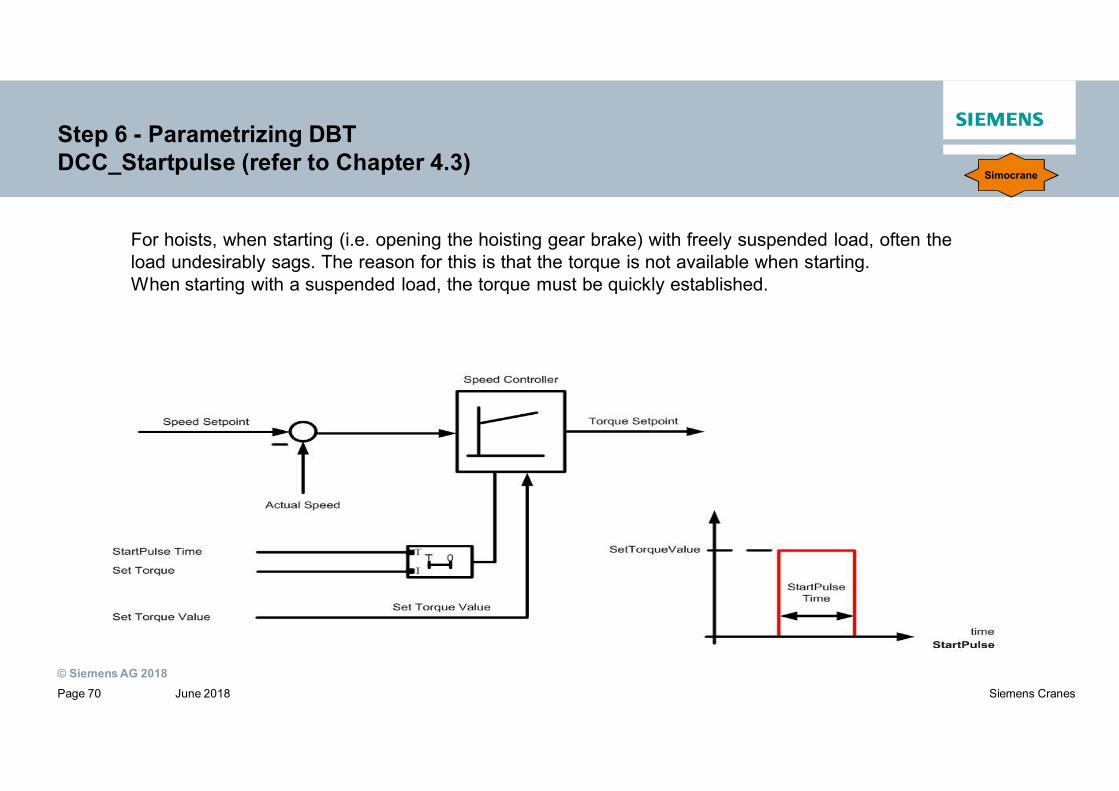
Step 6 - Parametrizing DBTDCC_Startpulse (refer to Chapter 4.3)
For hoists, when starting (i.e. opening the hoisting gear brake) with freely suspended load, often theload undesirably sags. The reason for this is that the torque is not available when starting.When starting with a suspended load, the torque must be quickly established.
Simocrane

© Siemens AG 2018June 2018Page 71 Siemens Cranes
Step 6 - Parametrizing DBTDCC_Startpulse in combination of Brake control
Brake Control
Start Pulse
Brake open
Simocrane
Brake close

© Siemens AG 2018June 2018Page 72 Siemens Cranes
Step 6 - Parametrizing DBTDCC_PreLimitSwitch (refer to Chapter 4.4)
This function prevents that the drive moves with full speed to the limit switch or to the safety buffer. Atotal of 4 different speed limits can be configured. Interconnect the maximum speed with speed limit 1.This limits speed to the maximum value.
Simocrane

© Siemens AG 2018June 2018Page 73 Siemens Cranes
Step 6 - Parametrizing DBTDCC_Overspeed (refer Chapter 4.5)
Function 1
to monitor the actual velocity for anoverspeed condition. Compared value can beeither in range of the rated speed or in fieldweakening area.
Function 2
to monitor continuously setpoint-actual valuedeviation
Simocrane
© Siemens AG 2018June 2018Page 74 Siemens Cranes
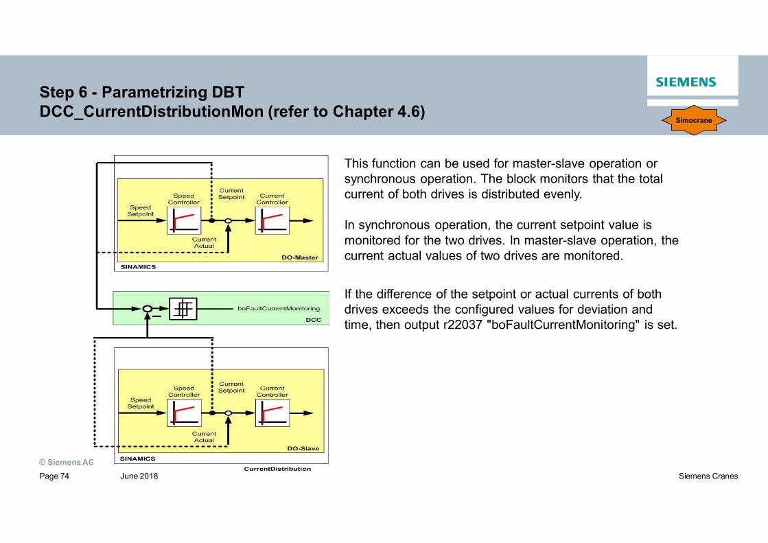
Step 6 - Parametrizing DBTDCC_CurrentDistributionMon (refer to Chapter 4.6)
This function can be used for master-slave operation orsynchronous operation. The block monitors that the totalcurrent of both drives is distributed evenly.
In synchronous operation, the current setpoint value ismonitored for the two drives. In master-slave operation, thecurrent actual values of two drives are monitored.
If the difference of the setpoint or actual currents of bothdrives exceeds the configured values for deviation andtime, then output r22037 "boFaultCurrentMonitoring" is set.
Simocrane

© Siemens AG 2018June 2018Page 75 Siemens Cranes
Step 6 - Parametrizing DBTDCC_LoadDependingFieldWeak (refer to Chapter 4.7 and 6.5)
When selecting field weakening, e.g. using the master switch, a supplementary speed setpoint for fieldweakening, which is permissible for the actual load, is generated.
Theoretical basics and equations
The steady-state load torque is calculatedas follows:
MM = MLoad + MFrictionMM: Motor torqueMLoad: Load torqueMFriction: Frictional torque
Commissioning instructions
1. To generate the measured variables (refer to chapter 6.5.2.1)2. Compensating the frictional torque (refer to chapter 6.5.2.2)3. Correcting the efficiency (refer to chapter 6.5.2.3)4. Calculating the physical size of the load (refer to chapter 6.5.2.4)
Simocrane

© Siemens AG 2018June 2018Page 76 Siemens Cranes
After commissioning save the project
After the Commissioning is finished, following steps must be done:⋅ Copy RAM to ROM (all settings will
be saved on CF card)
⋅ If the parameter settings in the CU310are changed online, then upload theproject to PG and save the project inthe STARTER.
⋅ Do a copy of the complete CF flash cardto the hard-disc as a backup.
Sinamics

© Siemens AG 2018June 2018Page 77 Siemens Cranes
Thank you for your attention!
Dr. Qing Chen
Product Manager
PD LD CR PSM PRM
E-Mail: [email protected]
siemens.com/answers