simple hand held calculating unit
TRANSCRIPT

International Journal of Embedded systems and Applications(IJESA) Vol.5, No.3, September 2015
DOI : 10.5121/ijesa.2015.5301 1
SIMPLE HAND-HELD CALCULATING UNIT
TO AID THE VISUALLY IMPAIRED WITH
VOICE OUTPUT
ShreedeepGangopadhyay1,Molay Kumar Mondal
1 and Arpita Pramanick
1
1Department of Electronics & Communication Engineering, Techno India, Salt Lake,
Kolkata
ABSTRACT A thorough understanding in mathematics enhances educational and occupational opportunities for all,
whether sighted or visually impaired.. However, solving complicated mathematical problems is difficult for
visually challenged students in schools and universities as the calculators available in the markets with
smooth input keys and LCD outputs are useless for them. Using the assistive technology which is basically
a service or product to help people with disabilities function more independently has removed barriers to
educate and employ people. An optimal solution for them is Braille calculator with audio output. In this paper, we have proposed a cost effective, hand-held, battery-driven, low power assistive device aiming the
visually impaired people from low income settings. The input is given through a 4 by 4 Membrane keypad
which has been Braille-embossed using indigenous methods. The output is announced in natural English by
the audio unit via speakers and/or headphones up to two places of decimal point. The system is
implemented on custom made open source Arduino platform, making it efficient and cost-effective.
KEYWORDS Braille Keypad, calculator, Arduino, assistive technology, visually challenged.
1. INTRODUCTION “For most of us, technology makes things easier; however for a person with disabilities, it
makes things possible”. Mathematics cultivates thinking and reasoning skills. It lays the
foundation for systematic thinking through the numerical and spatial aspects of the objects. As a subject, Mathematics plays an important role in society and the school curriculum is formulated
in such a way that Mathematics is given a central and significant place in it. Teaching and
learning of Mathematics is compulsory right from the primary level to the secondary level of
education. However reading and writing mathematics is fundamentally different than reading and writing text [2]. Traditionally Mathematics has been inaccessible to visually impaired and blind
students because its content is rich with visually presented concepts and information.
285 million people are estimated to be visually impaired worldwide: 39 million people are blind
and 246 million have low vision. About 90% of the world’s visually impaired people live in low
income settings [7].
Calculators are one of the most commonly required tools for computational purposes to students,
teachers, academicians and people working home, school and industry. However, people with
disabilities may have difficulty using standard calculators as calculators generally available in the market have smooth keys for input and LCD display for output. It offers few or no tactile clues to
allow a person with a visual impairment to orient him or herself to the keypad. Due to this, it is of

International Journal of Embedded systems and Applications(IJESA) Vol.5, No.3, September 2015
2
little use to those who are visually impaired. This was the primary motivation of this project.The
aim of this project is to explore alternatives which can improve the computational facilities of the
visually impaired. This project aims at finding a viable solution for this problem. This is done by the following ways: for input, we use tactile or haptic feedback in the form of Braille-embossed
keypad in place of smooth keypads used in regular calculators. Braille is a tactile writing
language of raised dots widely used by the visually impaired and is suitable for this purpose. For output, there is provision of both headphones and speakers to spell out the inputted mathematical
data and the result respectively.
2.COMPARATIVE STUDY OF EXISTING BRAILLE
CALCULATORS
From the literature survey, it was found that there are some ready-reckoners Talking Calculators (ORION TI-36X) available in the market made by Texas Instruments and other such technology
vendors that can read the display and may announce each key as it is pressed. However none of
the commercially available calculators have Braille keypads. Also, these products are of very high
cost ranging from $200 to $500 [5]. Some of the existing systems lack portability with insufficient power management. Some system uses relays to generate patterns and draws more
current as relays are used. One of the existing systems might resemble our proposed work as it
uses Braille touch screen interface to accept the inputs form the visually impaired persons [1].
However this system is as usual costly and yet to be full proof to be used by the blind person in
real life as the visually impaired find it difficult to swipe on the touch screen while using the calculator. Next comes a portable refreshable e-Braille which is able to read eBooks that are
stored inmicro-SD cards, reads SMS from mobile phonesover Bluetooth and display them as
Braille [3]. One of the major drawbacks of this system is it never allows user to input something
on his own. It always needs to be attached with a mobile phone and can’t operate separately. Due to the use of embossing mechanism in the earlier Braille display Typewriter model, the weight of
embossing tool will slow the rotational speed of stepper motor however light this may be, and
also add to the cost of product [6]. The LEO Braille Scientific Calculator provides a refreshable 8 dot, 8 cell braille displays. The calculator can compute standard arithmetic functions, plus square
root, trigonometry functions, logarithm, conversions, and financial functions. However, it is
available from LS&S Group at a very high cost of $999 [4]. As such, the aim of our project is
also to keep the cost of the handheld calculator in the range which is affordable by the visually impaired from humble economic background and it should be convenient to use as well. In
addition, the present work is aimed to eliminate the barriers that refrain visually impaired children
and adults from habituating the embedded device due to their lack of knowledge to use computers.
3. THE BRAILLE SYSTEM
This project utilizes Braille language as input to the calculator. Braille is a tactile writing system used by the blind and the visually impaired [12]. Braille is named after its creator, Frenchman
Louis Braille. It is developed for our haptic perception, a combination of the sense of touch,
movement and finger pressure. Braille characters are small rectangular blocks called cells that contain tiny palpable bumps called raised dots. Each cell is made up of six raised dots arranged in
a 3x2 membrane that relate to a letter, number or character. A fingertip can feel the whole cell at
once [2]. The system gives 63 combinations and one blank step [3]. These dots are raised roughly 0.9 mm by pressure from a cylindrical pin, causing identification underneath the thick paper [3].

International Journal of Embedded systems and Applications(IJESA) Vol.5, No.3, September 2015
3
Numbers are written in Braille using the NUMERAL SIGN (number sign), dots 3, 4, 5 and 6, The
following diagrams show sample Braille representations of numbers.
Figure 1: A sample example of Braille number system
Figure 2: Push button keyboard used as Braille keyboard
4. PROPOSED ARCHITECTURE FOR THE CALCULATING UNIT
So far, it can be seen that the commercially available solutions of the given problem are either insufficient or are costly, and beyond the means of people from weaker economic background.In
this proposed portable electronic Braille calculator, the main objective is to eliminate the barriers
that refrain visually impaired children and adults from habituating the embedded device due to
their lack of knowledge to use computers. Fig 3 shows the functional block diagram of our suggested calculating unit for visually impaired.
The software code associated with the model ensures that the calculator does not store any input if an operator key is pressed before typing any operand key.
International Journal of Embedded systems and Applications(IJESA) Vol.5, No.3, September 2015
4
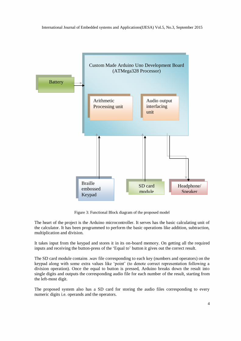
Figure 3: Functional Block diagram of the proposed model
The heart of the project is the Arduino microcontroller. It serves has the basic calculating unit of
the calculator. It has been programmed to perform the basic operations like addition, subtraction, multiplication and division.
It takes input from the keypad and stores it in its on-board memory. On getting all the required
inputs and receiving the button-press of the ‘Equal to’ button it gives out the correct result.
The SD card module contains .wav file corresponding to each key (numbers and operators) on the
keypad along with some extra values like ‘point’ (to denote correct representation following a division operation). Once the equal to button is pressed, Arduino breaks down the result into
single digits and outputs the corresponding audio file for each number of the result, starting from
the left-most digit.
The proposed system also has a SD card for storing the audio files corresponding to every
numeric digits i.e. operands and the operators.
Headphone/
Speaker
Custom Made Arduino Uno Development Board
(ATMega328 Processor)
SD card
module
Braille
embossed
Keypad
Battery
Arithmetic
Processing unit
Audio output
interfacing
unit
International Journal of Embedded systems and Applications(IJESA) Vol.5, No.3, September 2015
5
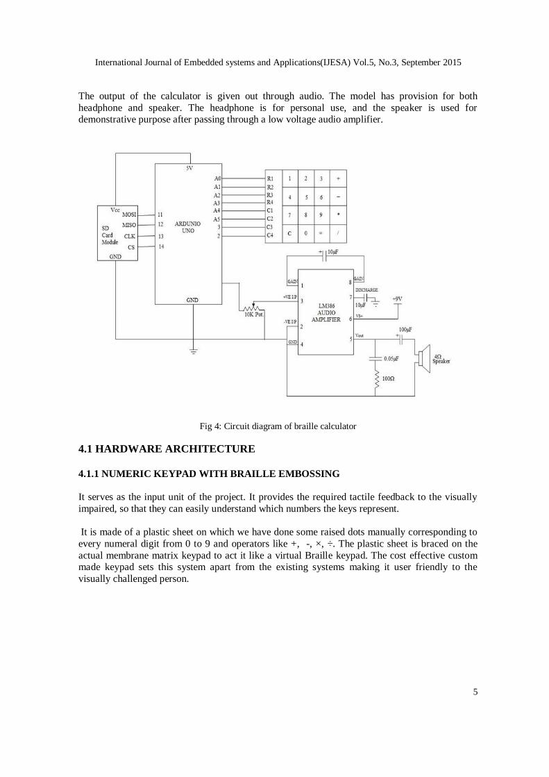
The output of the calculator is given out through audio. The model has provision for both
headphone and speaker. The headphone is for personal use, and the speaker is used for demonstrative purpose after passing through a low voltage audio amplifier.
Fig 4: Circuit diagram of braille calculator
4.1 HARDWARE ARCHITECTURE
4.1.1 NUMERIC KEYPAD WITH BRAILLE EMBOSSING
It serves as the input unit of the project. It provides the required tactile feedback to the visually
impaired, so that they can easily understand which numbers the keys represent.
It is made of a plastic sheet on which we have done some raised dots manually corresponding to
every numeral digit from 0 to 9 and operators like +, -, ×, ÷. The plastic sheet is braced on the
actual membrane matrix keypad to act it like a virtual Braille keypad. The cost effective custom made keypad sets this system apart from the existing systems making it user friendly to the
visually challenged person.

International Journal of Embedded systems and Applications(IJESA) Vol.5, No.3, September 2015
6
Figure 6: 4 by 4 Membrane Keypad Figure 7: Braille-embossed keypad
4.1.2 ARDUINO UNO MICROCONTROLLER
The hardware design architecture and theprototype code is to be designed and developed on our
own Arduino board consisting of Atmega328 microcontroller with only required components tofacilitate programming. The reason behind it is that all the components together cost only a
little over $3 US dollars as opposed to the $15 that theArduino Uno board sells for. Secondly, one
may not actually want a board, but may simply want the ATmega chip as the heart of the project.
In that case, we can just attach the hardware necessary to use the chip, and solder to the pins we
need to use without needing the board.The size of the board isconstrained by the size of our
device. The figurebelow (Fig 8) depicts the home made Arduino board that gives an estimate onthe size of our device. Only the Braille keypad, SD card reader and audio amplifier ,
headphone/speaker jackalong with the battery are included since these arethe components that
take up the most space.
Figure 9: Homemade Arduino board

International Journal of Embedded systems and Applications(IJESA) Vol.5, No.3, September 2015
7
4.1.3 SD CARD MODULE
The output audio samples are stored in the Adafruit SD card module as .wav files as the on-board
memory of the Uno board (32 KB) is not sufficient to store all the audio files [9]. The
communication between the microcontroller and the SD card uses SPI, which takes place on digital pins 11, 12, and 13. Additionally, another pin must be used to select the SD card. This can
be the hardware SS pin - pin 10 (on most Arduino boards).
Arduino Pin – SD Module Pin Pin 10 (SS) to CS
Pin 11 (MOSI) to DI
Pin 12 (MISO) to DO Pin 13 (SCK) to CLK
Also, G, + of SD Module are connected to GND and 5V of Arduino board respectively.
Figure 9: Adafruit SD Card Module
4.1.4 Audio Amplifier System with Speaker:
The LM386 is a power amplifier designed for use in low volt-age consumer applications. The
gain is internally set to 20 to keep external part count low, but the addition of an external resistor and capacitor between pins 1 and 8 will increase the gain to any value from 20 to 200 [8].The
inputs are ground referenced while the output automatically biases to one-half the supply voltage.
The quiescent power drain is only 24 mW when operating from a 6 volt supply, making the
LM386 ideal for battery operation If a speaker is not used then the output is directly obtained by connecting one pin of the headphone to the pin no. 9 of Arduino board and another pin to ground.
International Journal of Embedded systems and Applications(IJESA) Vol.5, No.3, September 2015
8
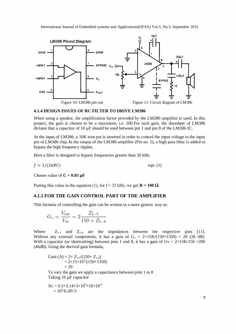
Figure 10: LM386 pin-out Figure 11: Circuit diagram of LM386
4.1.4 DESIGN ISSUES OF RC FILTER TO DRIVE LM386
When using a speaker, the amplification factor provided by the LM386 amplifier is used. In this
project, the gain is chosen to be a maximum, i.e. 200.For such gain, the datasheet of LM386 dictates that a capacitor of 10 µF should be used between pin 1 and pin 8 of the LM386 IC.
At the input of LM386, a 10K trim pot is inserted in order to control the input voltage to the input
pin of LM386 chip.At the output of the LM386 amplifier (Pin no. 5), a high pass filter is added to
bypass the high frequency ripples.
Here a filter is designed to bypass frequencies greater than 30 kHz.
) eqn. (1)
Chosen value of C = 0.05 µF
Putting this value in the equation (1), for f ≈ 32 kHz, we get R = 100 Ω.
4.1.5 FOR THE GAIN CONTROL PART OF THE AMPLIFIER
This formula of controlling the gain can be written in a more generic way as:
Where Z1-5 and Z1-8 are the impedances between the respective pins [11].
Without any external components, it has a gain of Gv = 2×15K/(150+1350) = 20 (26 dB). With a capacitor (or shortcutting) between pins 1 and 8, it has a gain of Gv = 2×15K/150 =200
(46dB). Using the derived gain formula,
Gain (A) = 2× Z1-5/(150+ Z1-8)
= 2×15×103/(150+1350)
= 20
To vary the gain we apply a capacitance between pins 1 to 8
Taking 10 µF capacitor
Xc = 0.5×3.14×3×103×10×10
-6
= 102/6.28×3

International Journal of Embedded systems and Applications(IJESA) Vol.5, No.3, September 2015
9
= 5 Ω
Now applying in the formulae:
Gain (A) = (2×15× 103)
/ (150+5)
= 150
4.2 SOFTWARE ARCHITECTURE
4.2.1 ARDUINO IDE
The open-source Arduino Software (IDE) makes it easy to write code and upload it to the board.
It runs on Windows, Mac OS X, and Linux [10]. The environment is written in Java and based on Processing and other open-source software that uses simplified library functions of C/C++. It
makes input/output operations much easier. Arduino is an open-source single-board
microcontroller, descendant of the open-source Wiring platform, designed to make the process of
using electronics in multidisciplinary projects more accessible.
Codes written using Arduino are called sketches. These sketches are written in the text editor. Sketches are saved with the file extension .ino. It has features for cutting/pasting and for
searching/replacing text. The message area gives feedback while saving and exporting and also
displays errors. The console displays text output by the Arduino environment including complete error messages and other information. The bottom right-hand corner of the window displays the
current board and serial port. The toolbar buttons allow you to verify and upload programs,
create, open, and save sketches, and open the serial monitor.
Features of the Arduino platform include:
Wide adoption and useful support from numerous websites, newsgroups, and user
forums.
Extensibility through plug-in boards for a broad range of applications, such as motor
control, wireless communication, audio processing, and data logging.
The Arduino IDE comes with a C/C++ library called "Wiring" (from the project of the
same name), which makes many common input/output operations much easier. Arduino
programs are written in C/C++, although users only need to two functions to make a run able program.
Setup () – a function run once at the start of a program that can initialize settings.
Loop () – a function called repeatedly until the board powers off.
Figure 12: Snapshot of Arduino IDE

International Journal of Embedded systems and Applications(IJESA) Vol.5, No.3, September 2015
10
The Arduino IDE uses the GNU tool chain and AVR Library to compile programs, and uses AVR
dude to upload programs to the board.
5. TESTING
Fig 13 shows the complete calculating unit including all the required modules starting from
ATMega 328 micro-controller, SD card module, provision of both headphone and speaker and the Braille embossed keypad-on a single Vero-board .It acts like a homemade embedded
systemhelping the visually impaired persons carry out simple mathematical calculations
confidently. The calculator has been demonstrated a number of times before students and teachers
alike, and every time it performed to the satisfaction of the audience.
Figure 13: The complete set up of the proposed system
The figure below shows explicitly the soldering (backside of the Vero-board) of the our calculator
that incorporates minimum possible wire for interconnection making it free from loose transition,
sudden malfunctioning and other hazards that might result due to overuse of wires.
Figure 14: The soldering of our breakout board
The system for the calculator has provision for displaying the results on the computer as well, to which the Arduino board is connected. This method of testing was used a number of times to test
the performance of the calculator before the audio output was introduced which correctly showed
the outputs.
International Journal of Embedded systems and Applications(IJESA) Vol.5, No.3, September 2015
11
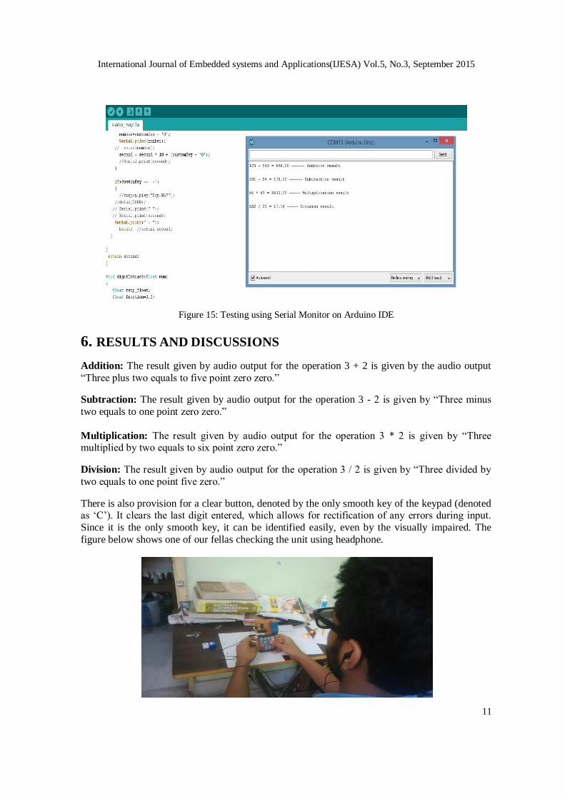
Figure 15: Testing using Serial Monitor on Arduino IDE
6. RESULTS AND DISCUSSIONS
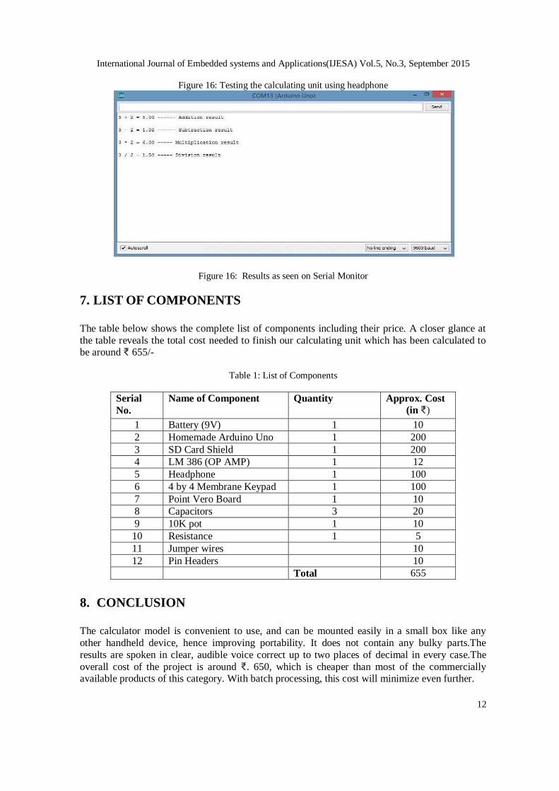
Addition: The result given by audio output for the operation 3 + 2 is given by the audio output
“Three plus two equals to five point zero zero.”
Subtraction: The result given by audio output for the operation 3 - 2 is given by “Three minus
two equals to one point zero zero.”
Multiplication: The result given by audio output for the operation 3 * 2 is given by “Three multiplied by two equals to six point zero zero.”
Division: The result given by audio output for the operation 3 / 2 is given by “Three divided by
two equals to one point five zero.”
There is also provision for a clear button, denoted by the only smooth key of the keypad (denoted as ‘C’). It clears the last digit entered, which allows for rectification of any errors during input.
Since it is the only smooth key, it can be identified easily, even by the visually impaired. The
figure below shows one of our fellas checking the unit using headphone.
International Journal of Embedded systems and Applications(IJESA) Vol.5, No.3, September 2015
12
Figure 16: Testing the calculating unit using headphone
Figure 16: Results as seen on Serial Monitor
7. LIST OF COMPONENTS
The table below shows the complete list of components including their price. A closer glance at
the table reveals the total cost needed to finish our calculating unit which has been calculated to be around ₹ 655/-
Table 1: List of Components
Serial
No.
Name of Component Quantity Approx. Cost
(in ₹)
1 Battery (9V) 1 10
2 Homemade Arduino Uno 1 200
3 SD Card Shield 1 200
4 LM 386 (OP AMP) 1 12
5 Headphone 1 100
6 4 by 4 Membrane Keypad 1 100
7 Point Vero Board 1 10
8 Capacitors 3 20
9 10K pot 1 10
10 Resistance 1 5
11 Jumper wires 10
12 Pin Headers 10
Total 655
8. CONCLUSION
The calculator model is convenient to use, and can be mounted easily in a small box like any
other handheld device, hence improving portability. It does not contain any bulky parts.The
results are spoken in clear, audible voice correct up to two places of decimal in every case.The
overall cost of the project is around ₹. 650, which is cheaper than most of the commercially available products of this category. With batch processing, this cost will minimize even further.

International Journal of Embedded systems and Applications(IJESA) Vol.5, No.3, September 2015
13
9. LIMITATIONS
Due to the small pin count of the ATMega328, it was not possible to incorporate more functions
to the calculator. As of now, the calculator lacks a decimal point on the keypad; hence, presently
the calculator does not have any provision for mathematical operations involving decimal numbers. This problem can be readily solved by using any other board of the Arduino family
which has a higher pin count (e.g. ArduinoMega) or by connecting another piece of ATMega328
in software serial mode with the former. By introducing higher pin count, the number of input
keypads can be increased, which will contribute to introduction of more mathematical functions. Also, the changes required in the software for this purpose is minimal and can be done easily.
10. FUTURE SCOPE The easy-to-use Arduino platform allows for easier software up-gradation. Any other
development board from the Arduino family can also be used with minimal changes to the
software code. Hence, adding more functions to the present model of the only calls for a bigger development board and minimal software change. Also, precision of the results after the decimal
point requires a software upgrade only. Here, it has been kept up to two places of decimal for
demonstrative purposes only.
11. APPRECIATION
This work won the best project award in all categories in the Eastern India Science & Engineering
Fair held at BITM in Kolkata earlier in this year.
12. REFERENCES
[1] Yoshit V. Gidh, Mahesh S. Latey, Arpita Roy, Kunal Shah, Savita , “Braille Calculator”, International
Journal Of Engineering And Computer Science ISSN:2319-7242 Volume 2 Issue 2 Feb 2013 Page
No. 481-382
[2] Sunil Kumar M.E –Karnataka University Braille language learner for blinds International Journal Of
infinite Innovations in technology 2012-2013Reg. No.:20120905|DOI:V1I2P05
[3] M.A.Raja, A.Arunya, DiptiYadav, G.Kanitha, R.Maheshwari , “Portable Refreshable E-Braille”, International Journal of Engineering Research and Applications (IJERA) ISSN: 2248-9622
www.ijera.com Vol. 3, Issue 1, January -February 2013, pp.1393-1397
[4] https://smartech.gatech.edu/bitstream/handle/1853/26265/Calculators.pdf
[5] Kumar J.A.V, Visu A , Raj M.S, Prabhu M.T, Kalaiselvi V.K.G , “A pragmatic approach to aid
visually impaired people in reading, visualizing and understanding textual contents with an automatic
electronic pen”, Computer Science Automation Engineering (CSAE), 2011 IEEE International
Conference.
[6] Moorey and I. Murray School of Electrical and Computer engineering Curtin University of
Technology, Kent street Bentley Western australia-6102:”Electronic Design of a low-cost Braille
Typewriter”
[7] World Health Organization (WHO)
[8] http://www.datasheetlib.com/datasheet/52982/lm386_national-semiconductor.html [9] https://www.sparkfun.com/products/12761
[10] http://arduino.cc/en/Main/arduinoBoardUno
[11] http://www.learningaboutelectronics.com/Articles/How-to-connect-a-LM386-audio-amplifier-chip
[12] http://en.wikipedia.org/wiki/Braille