simplex fault assistance guide reva...simplex fault assistance guide reva 29 april 2009 1.1.1...
TRANSCRIPT
SIMPLEX Fault Assistance Guide RevA REV 0 | 29 April 2009
Simplex Fire Products - Fault & Assistance Guide
2 of 72
SIMPLEX Fault Assistance Guide RevA 29 April 2009
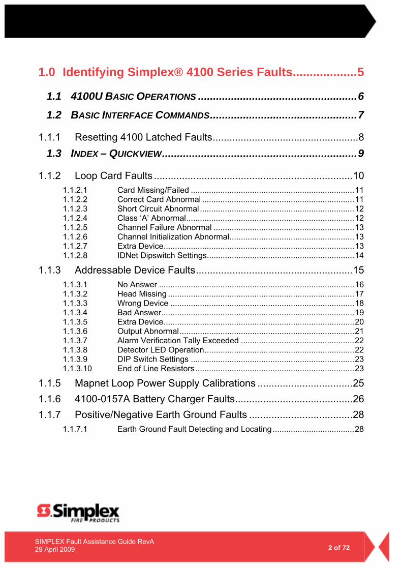
1.0 Identifying Simplex® 4100 Series Faults...................5
1.1 4100U BASIC OPERATIONS .....................................................6
1.2 BASIC INTERFACE COMMANDS.................................................7
1.1.1 Resetting 4100 Latched Faults....................................................8
1.3 INDEX – QUICKVIEW.................................................................9
1.1.2 Loop Card Faults .......................................................................10
1.1.2.1 Card Missing/Failed ........................................................................11 1.1.2.2 Correct Card Abnormal ...................................................................11 1.1.2.3 Short Circuit Abnormal ....................................................................12 1.1.2.4 Class ‘A’ Abnormal..........................................................................12 1.1.2.5 Channel Failure Abnormal ..............................................................13 1.1.2.6 Channel Initialization Abnormal.......................................................13 1.1.2.7 Extra Device....................................................................................13 1.1.2.8 IDNet Dipswitch Settings.................................................................14
1.1.3 Addressable Device Faults........................................................15
1.1.3.1 No Answer ......................................................................................16 1.1.3.2 Head Missing ..................................................................................17 1.1.3.3 Wrong Device .................................................................................18 1.1.3.4 Bad Answer.....................................................................................19 1.1.3.5 Extra Device....................................................................................20 1.1.3.6 Output Abnormal.............................................................................21 1.1.3.7 Alarm Verification Tally Exceeded ..................................................22 1.1.3.8 Detector LED Operation..................................................................22 1.1.3.9 DIP Switch Settings ........................................................................23 1.1.3.10 End of Line Resistors......................................................................23
1.1.5 Mapnet Loop Power Supply Calibrations ..................................25
1.1.6 4100-0157A Battery Charger Faults..........................................26
1.1.7 Positive/Negative Earth Ground Faults .....................................28
1.1.7.1 Earth Ground Fault Detecting and Locating ....................................28
3 of 72
SIMPLEX Fault Assistance Guide RevA 29 April 2009
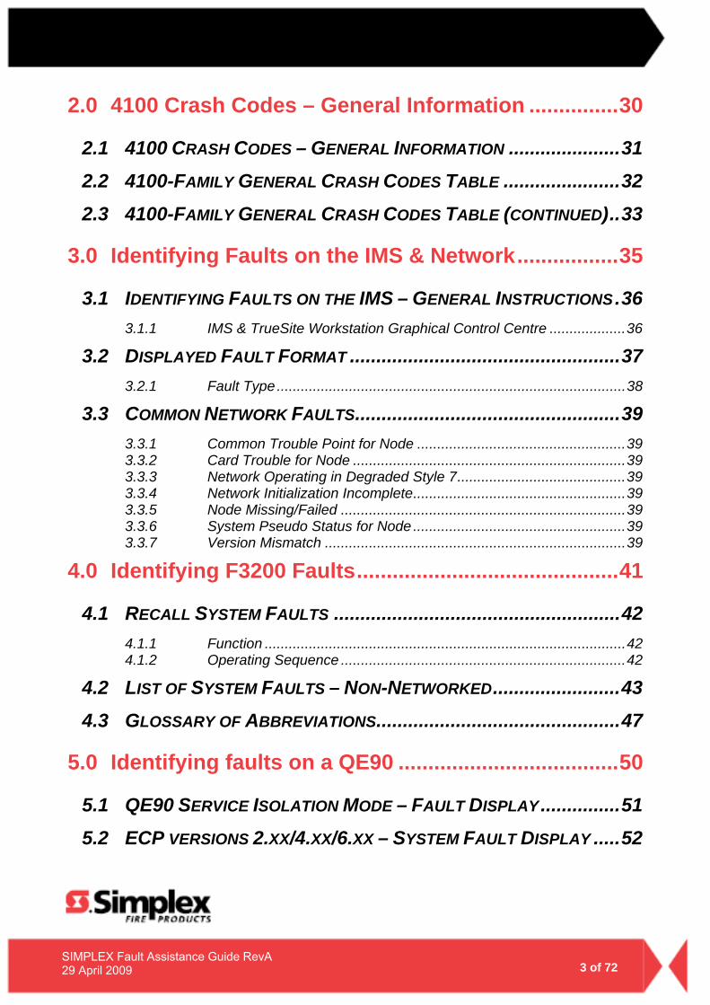
2.0 4100 Crash Codes – General Information ...............30
2.1 4100 CRASH CODES – GENERAL INFORMATION .....................31
2.2 4100-FAMILY GENERAL CRASH CODES TABLE ......................32
2.3 4100-FAMILY GENERAL CRASH CODES TABLE (CONTINUED)..33
3.0 Identifying Faults on the IMS & Network.................35
3.1 IDENTIFYING FAULTS ON THE IMS – GENERAL INSTRUCTIONS.36
3.1.1 IMS & TrueSite Workstation Graphical Control Centre ...................36
3.2 DISPLAYED FAULT FORMAT ...................................................37
3.2.1 Fault Type .......................................................................................38
3.3 COMMON NETWORK FAULTS..................................................39
3.3.1 Common Trouble Point for Node ....................................................39 3.3.2 Card Trouble for Node ....................................................................39 3.3.3 Network Operating in Degraded Style 7..........................................39 3.3.4 Network Initialization Incomplete.....................................................39 3.3.5 Node Missing/Failed .......................................................................39 3.3.6 System Pseudo Status for Node .....................................................39 3.3.7 Version Mismatch ...........................................................................39
4.0 Identifying F3200 Faults............................................41
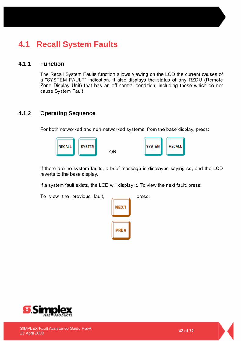
4.1 RECALL SYSTEM FAULTS ......................................................42
4.1.1 Function ..........................................................................................42 4.1.2 Operating Sequence .......................................................................42
4.2 LIST OF SYSTEM FAULTS – NON-NETWORKED........................43
4.3 GLOSSARY OF ABBREVIATIONS..............................................47
5.0 Identifying faults on a QE90 .....................................50
5.1 QE90 SERVICE ISOLATION MODE – FAULT DISPLAY...............51
5.2 ECP VERSIONS 2.XX/4.XX/6.XX – SYSTEM FAULT DISPLAY .....52
4 of 72
SIMPLEX Fault Assistance Guide RevA 29 April 2009
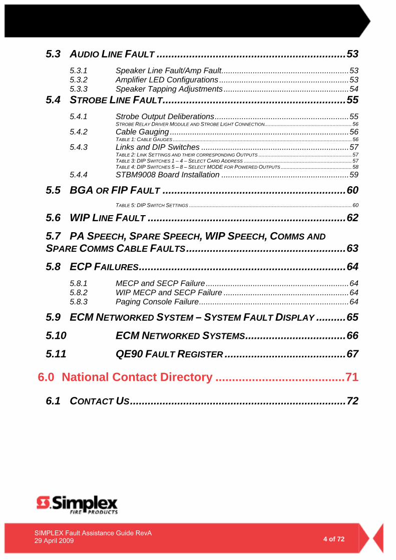
5.3 AUDIO LINE FAULT ................................................................53
5.3.1 Speaker Line Fault/Amp Fault.........................................................53 5.3.2 Amplifier LED Configurations ..........................................................53 5.3.3 Speaker Tapping Adjustments ........................................................54
5.4 STROBE LINE FAULT..............................................................55
5.4.1 Strobe Output Deliberations............................................................55 STROBE RELAY DRIVER MODULE AND STROBE LIGHT CONNECTION........................................................... 56
5.4.2 Cable Gauging ................................................................................56 TABLE 1: CABLE GAUGES ......................................................................................................................... 56
5.4.3 Links and DIP Switches ..................................................................57 TABLE 2: LINK SETTINGS AND THEIR CORRESPONDING OUTPUTS ............................................................... 57 TABLE 3: DIP SWITCHES 1 – 4 – SELECT CARD ADDRESS ......................................................................... 57 TABLE 4: DIP SWITCHES 5 – 8 – SELECT MODE FOR POWERED OUTPUTS ................................................ 58
5.4.4 STBM9008 Board Installation .........................................................59
5.5 BGA OR FIP FAULT ..............................................................60
TABLE 5: DIP SWITCH SETTINGS .............................................................................................................. 60
5.6 WIP LINE FAULT ...................................................................62
5.7 PA SPEECH, SPARE SPEECH, WIP SPEECH, COMMS AND SPARE COMMS CABLE FAULTS......................................................63
5.8 ECP FAILURES......................................................................64
5.8.1 MECP and SECP Failure ................................................................64 5.8.2 WIP MECP and SECP Failure ........................................................64 5.8.3 Paging Console Failure...................................................................64
5.9 ECM NETWORKED SYSTEM – SYSTEM FAULT DISPLAY ..........65
5.10 ECM NETWORKED SYSTEMS..................................66
5.11 QE90 FAULT REGISTER .........................................67
6.0 National Contact Directory .......................................71
6.1 CONTACT US.........................................................................72
SIMPLEX Fault Assistance Guide RevA REV 0 | 29 April 2009
1.0 Identifying Simplex® 4100 Series Faults
6 of 72
SIMPLEX Fault Assistance Guide RevA 29 April 2009
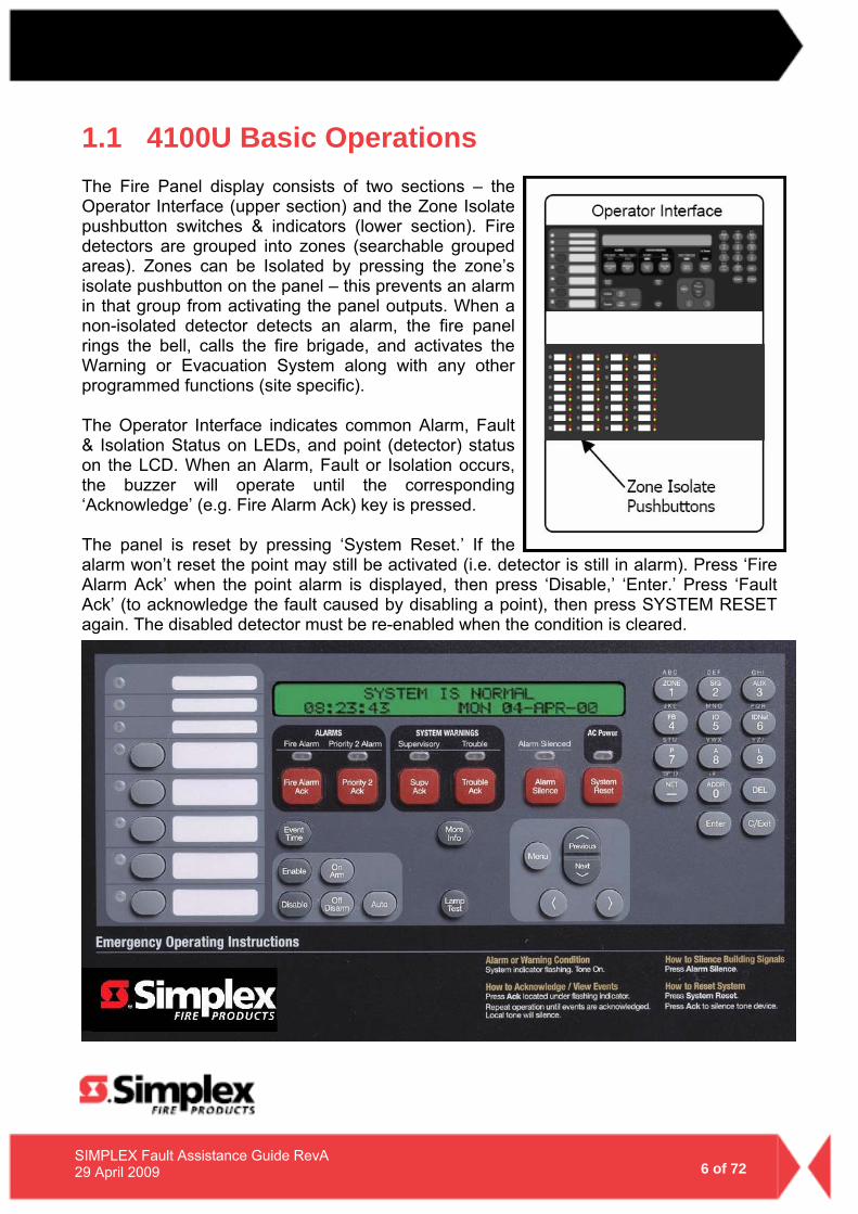
1.1 4100U Basic Operations The Fire Panel display consists of two sections – the Operator Interface (upper section) and the Zone Isolate pushbutton switches & indicators (lower section). Fire detectors are grouped into zones (searchable grouped areas). Zones can be Isolated by pressing the zone’s isolate pushbutton on the panel – this prevents an alarm in that group from activating the panel outputs. When a non-isolated detector detects an alarm, the fire panel rings the bell, calls the fire brigade, and activates the Warning or Evacuation System along with any other programmed functions (site specific). The Operator Interface indicates common Alarm, Fault & Isolation Status on LEDs, and point (detector) status on the LCD. When an Alarm, Fault or Isolation occurs, the buzzer will operate until the corresponding ‘Acknowledge’ (e.g. Fire Alarm Ack) key is pressed. The panel is reset by pressing ‘System Reset.’ If the alarm won’t reset the point may still be activated (i.e. detector is still in alarm). Press ‘Fire Alarm Ack’ when the point alarm is displayed, then press ‘Disable,’ ‘Enter.’ Press ‘Fault Ack’ (to acknowledge the fault caused by disabling a point), then press SYSTEM RESET again. The disabled detector must be re-enabled when the condition is cleared.
7 of 72
SIMPLEX Fault Assistance Guide RevA 29 April 2009
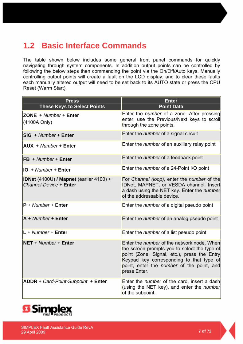
1.2 Basic Interface Commands The table shown below includes some general front panel commands for quickly navigating through system components. In addition output points can be controlled by following the below steps then commanding the point via the On/Off/Auto keys. Manually controlling output points will create a fault on the LCD display, and to clear these faults each manually altered output will need to be set back to its AUTO state or press the CPU Reset (Warm Start).
Press These Keys to Select Points
Enter Point Data
ZONEᅠ+ Number + Enter (4100A Only)
Enter the number of a zone. After pressing enter, use the Previous/Next keys to scroll through the zone points.
SIGᅠ+ Number + Enter Enter the number of a signal circuit
AUXᅠ+ Number + Enter Enter the number of an auxiliary relay point
FBᅠ+ Number + Enter Enter the number of a feedback point
IOᅠ+ Number + Enter Enter the number of a 24-Point I/O point
IDNet (4100U) / Mapnet (earlier 4100) + Channel-Device + Enter
For Channel (loop), enter the number of the IDNet, MAPNET, or VESDA channel. Insert a dash using the NET key. Enter the numberof the addressable device.
P + Number + Enter Enter the number of a digital pseudo point
A + Number + Enter Enter the number of an analog pseudo point
L + Number + Enter Enter the number of a list pseudo point
NET + Number + Enter Enter the number of the network node. When the screen prompts you to select the type of point (Zone, Signal, etc.), press the Entry Keypad key corresponding to that type of point, enter the number of the point, and press Enter.
ADDR + Card-Point-Subpoint + Enter Enter the number of the card, insert a dash (using the NET key), and enter the numberof the subpoint.
8 of 72
SIMPLEX Fault Assistance Guide RevA 29 April 2009
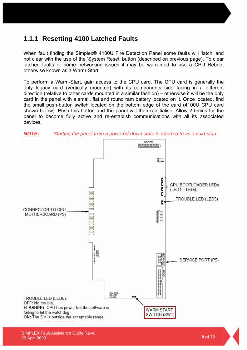
1.1.1 Resetting 4100 Latched Faults When fault finding the Simplex® 4100U Fire Detection Panel some faults will ‘latch’ and not clear with the use of the ‘System Reset’ button (described on previous page). To clear latched faults or some networking issues it may be warranted to use a CPU Reboot otherwise known as a Warm-Start. To perform a Warm-Start, gain access to the CPU card. The CPU card is generally the only legacy card (vertically mounted) with its components side facing in a different direction (relative to other cards mounted in a similar fashion) – otherwise it will be the only card in the panel with a small, flat and round ram battery located on it. Once located, find the small push-button switch located on the bottom edge of the card (4100U CPU card shown below). Push this button and the panel will then reinitialise. Allow 2-5mins for the panel to become fully active and re-establish communications with all its associated devices. NOTE: Starting the panel from a powered-down state is referred to as a cold-start.
9 of 72
SIMPLEX Fault Assistance Guide RevA 29 April 2009
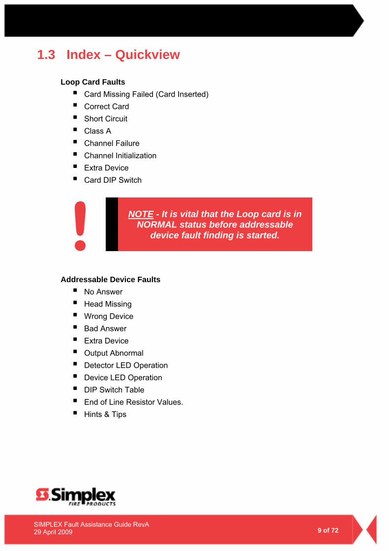
1.3 Index – Quickview
Loop Card Faults Card Missing Failed (Card Inserted) Correct Card Short Circuit Class A Channel Failure Channel Initialization Extra Device Card DIP Switch
Addressable Device Faults
No Answer Head Missing Wrong Device Bad Answer Extra Device Output Abnormal Detector LED Operation Device LED Operation DIP Switch Table End of Line Resistor Values. Hints & Tips
NOTE - It is vital that the Loop card is in NORMAL status before addressable
device fault finding is started. !
10 of 72
SIMPLEX Fault Assistance Guide RevA 29 April 2009
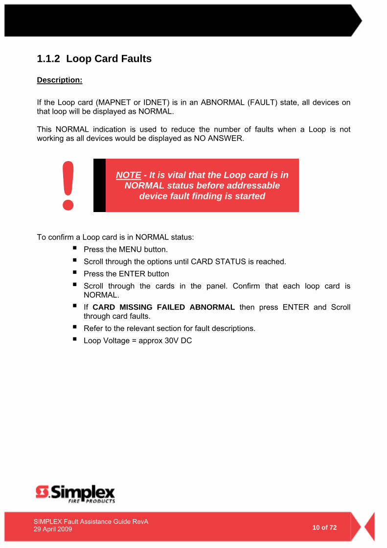
1.1.2 Loop Card Faults Description:
If the Loop card (MAPNET or IDNET) is in an ABNORMAL (FAULT) state, all devices on that loop will be displayed as NORMAL.
This NORMAL indication is used to reduce the number of faults when a Loop is not working as all devices would be displayed as NO ANSWER.
To confirm a Loop card is in NORMAL status:
Press the MENU button. Scroll through the options until CARD STATUS is reached. Press the ENTER button Scroll through the cards in the panel. Confirm that each loop card is
NORMAL. If CARD MISSING FAILED ABNORMAL then press ENTER and Scroll
through card faults. Refer to the relevant section for fault descriptions. Loop Voltage = approx 30V DC
NOTE - It is vital that the Loop card is in NORMAL status before addressable
device fault finding is started !
11 of 72
SIMPLEX Fault Assistance Guide RevA 29 April 2009
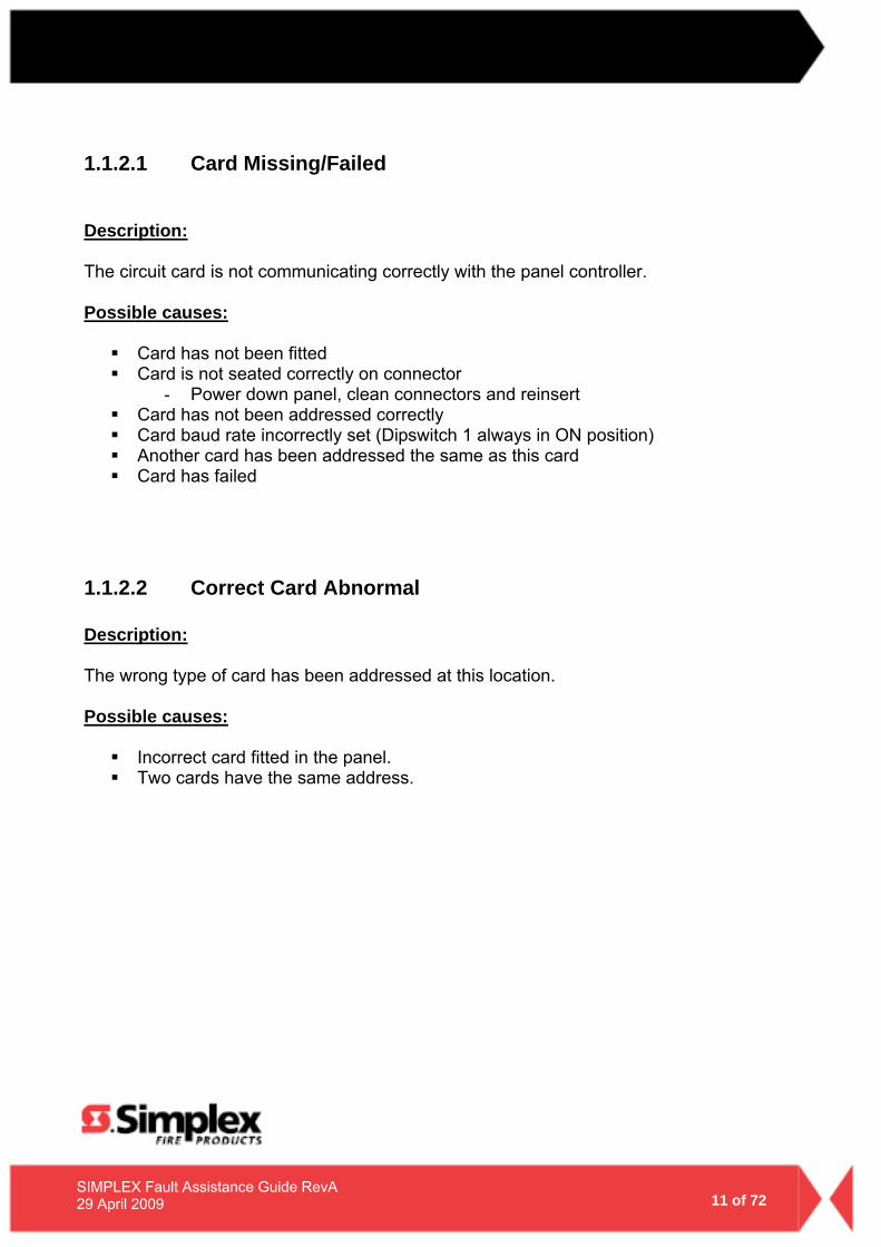
1.1.2.1 Card Missing/Failed Description: The circuit card is not communicating correctly with the panel controller. Possible causes:
Card has not been fitted Card is not seated correctly on connector
- Power down panel, clean connectors and reinsert Card has not been addressed correctly Card baud rate incorrectly set (Dipswitch 1 always in ON position) Another card has been addressed the same as this card Card has failed
1.1.2.2 Correct Card Abnormal Description: The wrong type of card has been addressed at this location. Possible causes:
Incorrect card fitted in the panel. Two cards have the same address.
12 of 72
SIMPLEX Fault Assistance Guide RevA 29 April 2009
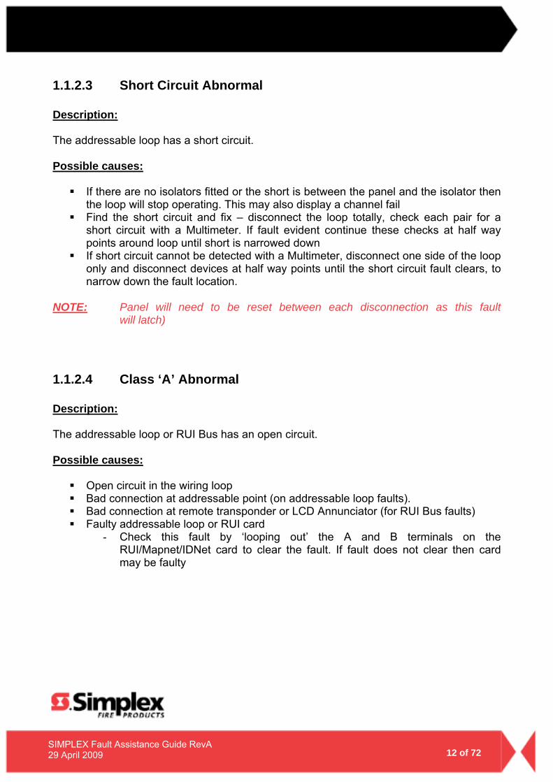
1.1.2.3 Short Circuit Abnormal Description: The addressable loop has a short circuit. Possible causes:
If there are no isolators fitted or the short is between the panel and the isolator then the loop will stop operating. This may also display a channel fail
Find the short circuit and fix – disconnect the loop totally, check each pair for a short circuit with a Multimeter. If fault evident continue these checks at half way points around loop until short is narrowed down
If short circuit cannot be detected with a Multimeter, disconnect one side of the loop only and disconnect devices at half way points until the short circuit fault clears, to narrow down the fault location.
NOTE: Panel will need to be reset between each disconnection as this fault will latch)
1.1.2.4 Class ‘A’ Abnormal Description: The addressable loop or RUI Bus has an open circuit. Possible causes:
Open circuit in the wiring loop Bad connection at addressable point (on addressable loop faults). Bad connection at remote transponder or LCD Annunciator (for RUI Bus faults) Faulty addressable loop or RUI card
- Check this fault by ‘looping out’ the A and B terminals on the RUI/Mapnet/IDNet card to clear the fault. If fault does not clear then card may be faulty
13 of 72
SIMPLEX Fault Assistance Guide RevA 29 April 2009
1.1.2.5 Channel Failure Abnormal Description: The Loop card cannot communicate with any device on the loop. Be aware all devices associated with this loop will indicate a ‘Normal’ state to prevent multiple faults per display. Possible causes:
The Loop has a Short circuit The Loop has an Earth fault The Loop is not connected or incorrectly connected
1.1.2.6 Channel Initialization Abnormal Description: This fault typically occurs at startup with IDNet loops and will normally clear after a couple of minutes if a lot of Isolators are fitted. Possible causes:
If the fault continually re-appears the loop length maybe too long or too noisy – Contact you local Simplex® branch for assistance
Possible bad device causing communication errors - Disconnect devices at half way points until the fault clears to locate
the faulty device
1.1.2.7 Extra Device Description: A device is located on the addressable loop that is addressed at a location that is not programmed. Possible causes: The panel has identified a device/card at an address that is not in the panel programming. Refer to the Extra Device section of Device Faults (Page 20).
A card/device may be incorrectly addressed bringing up an Extra Device fault, but the programmed device’s address will display “Points defined but not inserted.”
14 of 72
SIMPLEX Fault Assistance Guide RevA 29 April 2009
1.1.2.8 IDNet Dipswitch Settings 1. Devices are supplied with DIPSWITCH switch ALL ON (set to 0) 2. DIPSWITCHES are labeled 1 to 8
Switch 1 = MUST BE ON (Baud Rate) Switch 2 = 64 Switch 3 = 32 Switch 4 = 16 Switch 5 = 8 Switch 6 = 4 Switch 7 = 2 Switch 8 = 1
3. Turn Switch OFF to add the above number to the address.
Examples: Address 5 = Switch 6 & 8 OFF all others ON. Address 23 = Switch 4, 6, 7 & 8 OFF others ON.
NOTE - This is reverse of how the addressable devices address’ are set. [Refer to section 1.1.3.9 – page 23]
15 of 72
SIMPLEX Fault Assistance Guide RevA 29 April 2009
1.1.3 Addressable Device Faults To confirm a Loop card is in NORMAL status:
Press the MENU button. Scroll through the options until CARD STATUS is reached. Press the ENTER button Scroll through the cards in the panel. Confirm that each loop card is
NORMAL. If CARD MISSING FAILED ABNORMAL then press ENTER and Scroll
through card faults. Refer to the relevant section for fault descriptions.
NOTE - It is vital that the Loop card is in NORMAL status before addressable
device fault finding is started !
16 of 72
SIMPLEX Fault Assistance Guide RevA 29 April 2009
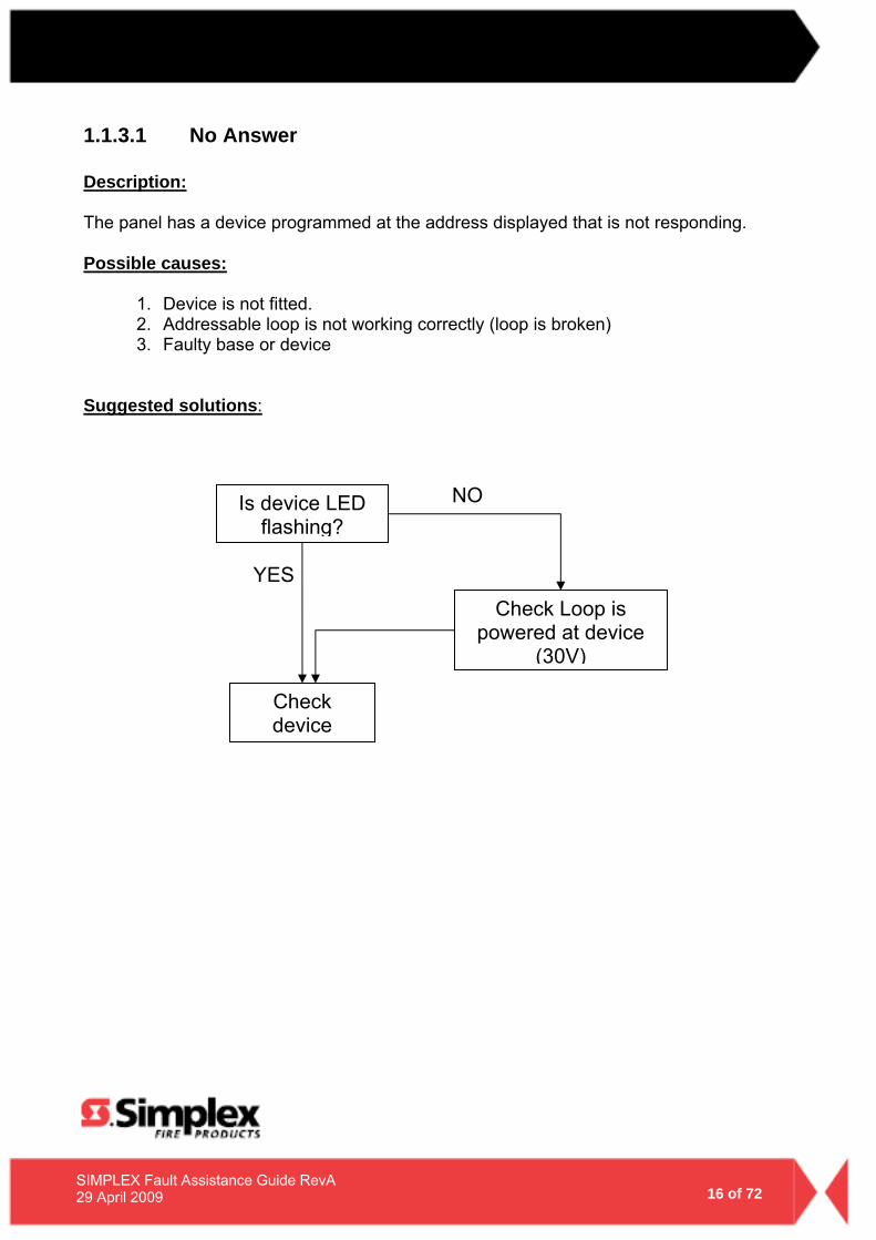
1.1.3.1 No Answer Description: The panel has a device programmed at the address displayed that is not responding. Possible causes:
1. Device is not fitted. 2. Addressable loop is not working correctly (loop is broken) 3. Faulty base or device
Suggested solutions:
NO
YES
Check device
Check Loop is powered at device
(30V)
Is device LED flashing?
17 of 72
SIMPLEX Fault Assistance Guide RevA 29 April 2009
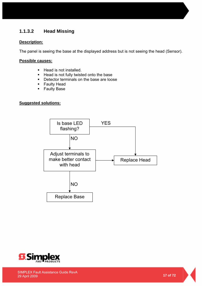
1.1.3.2 Head Missing Description: The panel is seeing the base at the displayed address but is not seeing the head (Sensor). Possible causes:
Head is not installed. Head is not fully twisted onto the base Detector terminals on the base are loose Faulty Head Faulty Base
Suggested solutions:
NO
NO
YES
Replace Head Adjust terminals to
make better contact with head
Is base LED flashing?
Replace Base
18 of 72
SIMPLEX Fault Assistance Guide RevA 29 April 2009
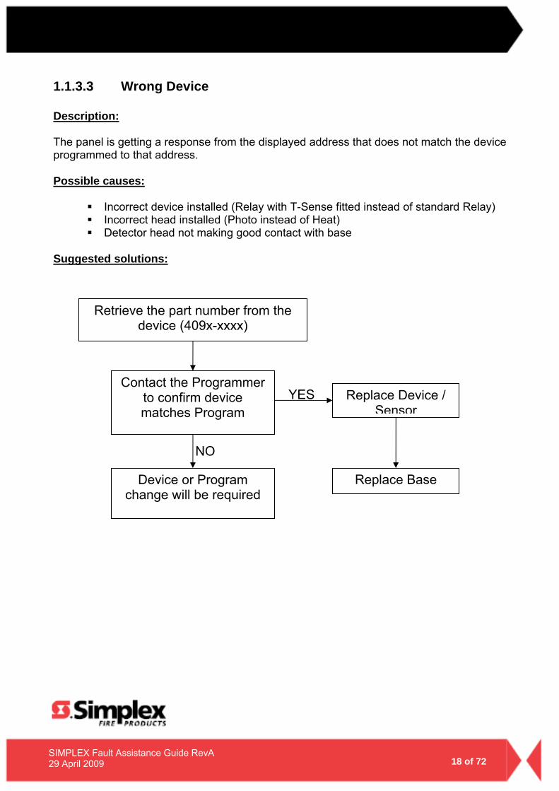
1.1.3.3 Wrong Device Description: The panel is getting a response from the displayed address that does not match the device programmed to that address. Possible causes:
Incorrect device installed (Relay with T-Sense fitted instead of standard Relay) Incorrect head installed (Photo instead of Heat) Detector head not making good contact with base
Suggested solutions:
NO
YES Replace Device / Sensor
Retrieve the part number from the device (409x-xxxx)
Device or Program change will be required
Replace Base
Contact the Programmer to confirm device matches Program
19 of 72
SIMPLEX Fault Assistance Guide RevA 29 April 2009
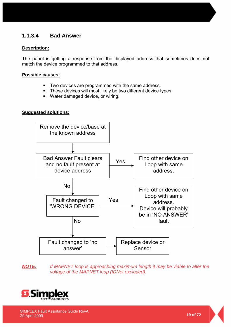
1.1.3.4 Bad Answer Description: The panel is getting a response from the displayed address that sometimes does not match the device programmed to that address. Possible causes:
Two devices are programmed with the same address. These devices will most likely be two different device types. Water damaged device, or wiring.
Suggested solutions:
NOTE: If MAPNET loop is approaching maximum length it may be viable to alter the
voltage of the MAPNET loop (IDNet excluded).
No
Yes
Yes
No
Find other device on Loop with same
address.
Fault changed to ‘WRONG DEVICE’
Bad Answer Fault clears and no fault present at
device address
Fault changed to ‘no answer’
Remove the device/base at the known address
Find other device on Loop with same
address. Device will probably be in ‘NO ANSWER’
fault
Replace device or Sensor
20 of 72
SIMPLEX Fault Assistance Guide RevA 29 April 2009
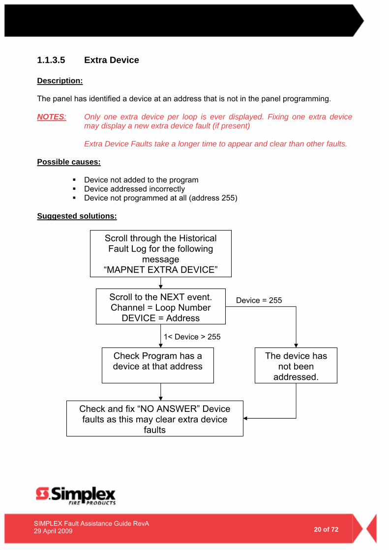
1.1.3.5 Extra Device Description: The panel has identified a device at an address that is not in the panel programming.
NOTES: Only one extra device per loop is ever displayed. Fixing one extra device
may display a new extra device fault (if present)
Extra Device Faults take a longer time to appear and clear than other faults. Possible causes:
Device not added to the program Device addressed incorrectly Device not programmed at all (address 255)
Suggested solutions:
1< Device > 255
Device = 255
The device has not been
addressed.
Scroll to the NEXT event. Channel = Loop Number
DEVICE = Address
Scroll through the Historical Fault Log for the following
message “MAPNET EXTRA DEVICE”
Check Program has a device at that address
Check and fix “NO ANSWER” Device faults as this may clear extra device
faults
21 of 72
SIMPLEX Fault Assistance Guide RevA 29 April 2009
1.1.3.6 Output Abnormal Description: Observed when the output of a Relay, Sounder or Isolator base is not responding correctly. Possible causes:
ISOLATOR Base A Short circuit has occurred on the addressable loop and the Isolator Base has not
been able to reset correctly
SOUNDER or RELAY Base 24 Volt supply to Sounder base is not present
Suggested solutions:
ISOLATOR Base – If short circuit fault has been corrected press ‘CPU RESET’ (Warm Start) to reinitialise the isolator base
SOUNDER or RELAY Base - Check wiring and 24V fused distribution board in
panel
22 of 72
SIMPLEX Fault Assistance Guide RevA 29 April 2009
1.1.3.7 Alarm Verification Tally Exceeded
NOTE: This fault could indicate a faulty detector in the field. Check for previous faults and note in the Log book the time and date this fault occurred.
1. Log in at Level 4 2. Select P214 3. Force Point ON 4. Reset CPU (use button on CPU – refer to Page 7) to clear Simplex®
Service Fault
1.1.3.8 Detector LED Operation Off
Detector is not communicating with the Panel Two Detectors on the same address The Head is not fitted correctly
Flash
Detector is communicating with the panel Flash speed does not provide any information
On
Detector is in ALARM or FAULT If no Head fitted then EXTRA DEVICE fault. Detector LED may become latched on if multiple faults occur to the same
detector. To Reset the LED warm boot the fire panel
23 of 72
SIMPLEX Fault Assistance Guide RevA 29 April 2009
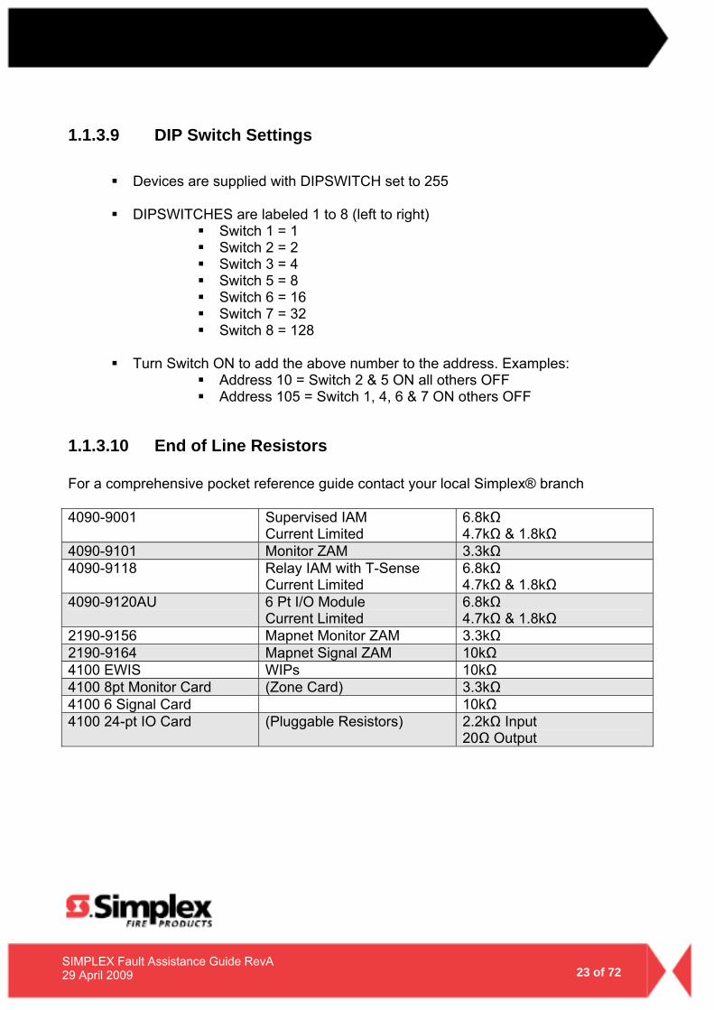
1.1.3.9 DIP Switch Settings
Devices are supplied with DIPSWITCH set to 255
DIPSWITCHES are labeled 1 to 8 (left to right) Switch 1 = 1 Switch 2 = 2 Switch 3 = 4 Switch 5 = 8 Switch 6 = 16 Switch 7 = 32 Switch 8 = 128
Turn Switch ON to add the above number to the address. Examples:
Address 10 = Switch 2 & 5 ON all others OFF Address 105 = Switch 1, 4, 6 & 7 ON others OFF
1.1.3.10 End of Line Resistors
For a comprehensive pocket reference guide contact your local Simplex® branch 4090-9001 Supervised IAM
Current Limited 6.8kΩ 4.7kΩ & 1.8kΩ
4090-9101 Monitor ZAM 3.3kΩ 4090-9118 Relay IAM with T-Sense
Current Limited 6.8kΩ 4.7kΩ & 1.8kΩ
4090-9120AU 6 Pt I/O Module Current Limited
6.8kΩ 4.7kΩ & 1.8kΩ
2190-9156 Mapnet Monitor ZAM 3.3kΩ 2190-9164 Mapnet Signal ZAM 10kΩ 4100 EWIS WIPs 10kΩ 4100 8pt Monitor Card (Zone Card) 3.3kΩ 4100 6 Signal Card 10kΩ 4100 24-pt IO Card (Pluggable Resistors) 2.2kΩ Input
20Ω Output
24 of 72
SIMPLEX Fault Assistance Guide RevA 29 April 2009
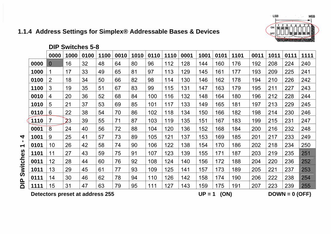
1.1.4 Address Settings for Simplex® Addressable Bases & Devices
DIP Switches 5-8 0000 1000 0100 1100 0010 1010 0110 1110 0001 1001 0101 1101 0011 1011 0111 1111
0000 0 16 32 48 64 80 96 112 128 144 160 176 192 208 224 240 1000 1 17 33 49 65 81 97 113 129 145 161 177 193 209 225 241 0100 2 18 34 50 66 82 98 114 130 146 162 178 194 210 226 242 1100 3 19 35 51 67 83 99 115 131 147 163 179 195 211 227 243 0010 4 20 36 52 68 84 100 116 132 148 164 180 196 212 228 244 1010 5 21 37 53 69 85 101 117 133 149 165 181 197 213 229 245 0110 6 22 38 54 70 86 102 118 134 150 166 182 198 214 230 246 1110 7 23 39 55 71 87 103 119 135 151 167 183 199 215 231 247 0001 8 24 40 56 72 88 104 120 136 152 168 184 200 216 232 248 1001 9 25 41 57 73 89 105 121 137 153 169 185 201 217 233 249 0101 10 26 42 58 74 90 106 122 138 154 170 186 202 218 234 250 1101 11 27 43 59 75 91 107 123 139 155 171 187 203 219 235 251 0011 12 28 44 60 76 92 108 124 140 156 172 188 204 220 236 252 1011 13 29 45 61 77 93 109 125 141 157 173 189 205 221 237 253 0111 14 30 46 62 78 94 110 126 142 158 174 190 206 222 238 254
DIP
Sw
itche
s 1
- 4
1111 15 31 47 63 79 95 111 127 143 159 175 191 207 223 239 255 Detectors preset at address 255 UP = 1 (ON) DOWN = 0 (OFF)
25 of 72
SIMPLEX Fault Assistance Guide RevA 29 April 2009
1.1.5 Mapnet Loop Power Supply Calibrations It is possible to recalibrate the MAPNET Loop Power Supply (excluding IDNet) output to possibly overcome a number of issues. This Calibration should NOT normally be attempted unless there are some site issues that are occurring and not easily diagnose/rectified. You should consider the Calibration option if
There are numerous, or intermittent numerous Bad Answers and No Answers occurring on a loop that has been 100% correctly addressed and wired/terminated correctly
The MAPNET loop voltage is not fluctuating between 36-38 Volts
NOTE: The MAPNET loop voltage will fluctuate normally as it is transmitting digital data at all times when powered
The MAPNET loop length guidelines and restrictions are not adhered to, and there is
no other solution available. (i.e. the loop length exceeds the recommended maximum of 1000m)
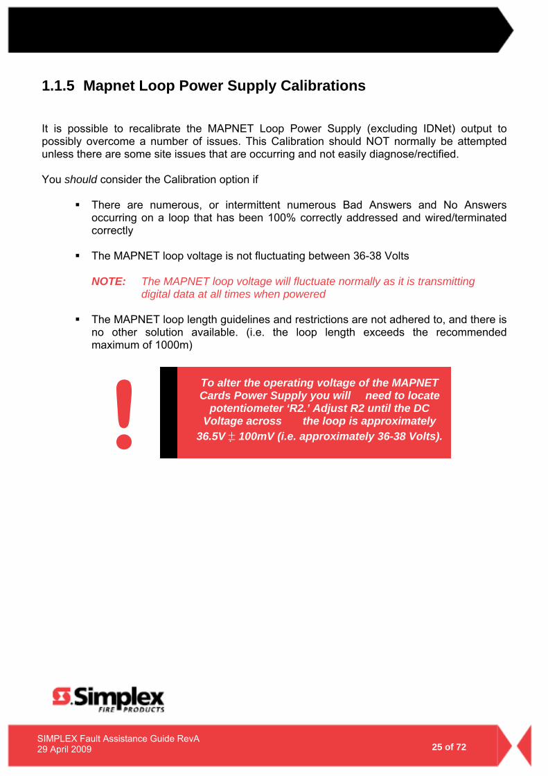
To alter the operating voltage of the MAPNET Cards Power Supply you will need to locate
potentiometer ‘R2.’ Adjust R2 until the DC Voltage across the loop is approximately
36.5V ± 100mV (i.e. approximately 36-38 Volts). !
26 of 72
SIMPLEX Fault Assistance Guide RevA 29 April 2009
1.1.6 4100-0157A Battery Charger Faults There are a number of Battery Charger Faults that can arise during the operational lifetime of a panel. You may observe one of the following Faults; Charger 2% out of range Battery Charger Supply incorrect To correctly measure the output voltage you will need to follow the steps below.
1. To prevent damage to the system, disconnect the batteries & power down the system, disconnect the power & comms harnesses from the Power Supply.
2. Connect the Multimeter to the battery leads (with batteries disconnected), power
up & measure the voltage. Calculate the difference between the measured voltage & 27.6v.
NOTE: After 90 seconds, the voltage will drop to <24v. If this happens, power down & start again.
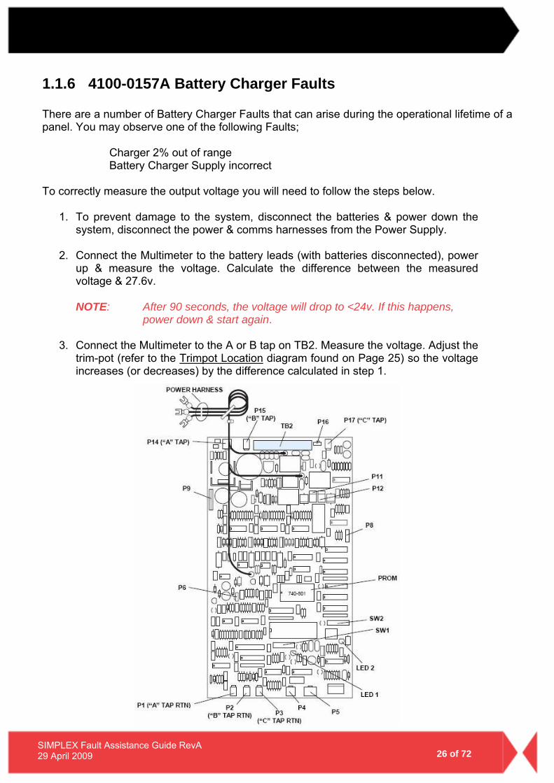
3. Connect the Multimeter to the A or B tap on TB2. Measure the voltage. Adjust the
trim-pot (refer to the Trimpot Location diagram found on Page 25) so the voltage increases (or decreases) by the difference calculated in step 1.
27 of 72
SIMPLEX Fault Assistance Guide RevA 29 April 2009
4. Measure the voltage on the battery leads. You may have to power down & up
again to reset the power supply. If the voltage is correct, power down, re-connect the power & comms harnesses & return the system to normal.
5. If the voltage is not correct, repeat steps 1 & 2.
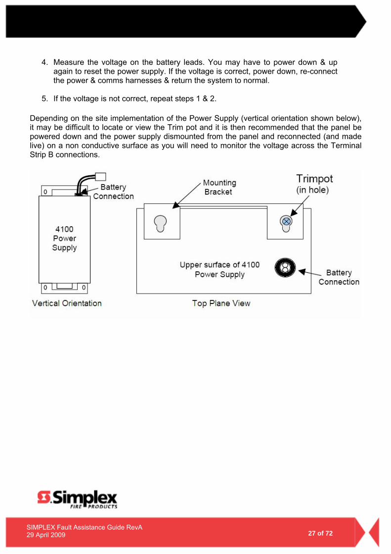
Depending on the site implementation of the Power Supply (vertical orientation shown below), it may be difficult to locate or view the Trim pot and it is then recommended that the panel be powered down and the power supply dismounted from the panel and reconnected (and made live) on a non conductive surface as you will need to monitor the voltage across the Terminal Strip B connections.
28 of 72
SIMPLEX Fault Assistance Guide RevA 29 April 2009
1.1.7 Positive/Negative Earth Ground Faults Simplex 4100 Series Fire Panels have the ability to detect positive or negative Earth Ground Faults. An Earth Ground Fault occurs when an electrical circuit is shorted to ground. It is imperative that Earth Ground Faults are located and repaired as multiple earth faults can disable communications meaning small or large components of the Fire Detection System may not function correctly (i.e. multiple earth faults on a Mapnet loop can disable the entire loops communications channel rendering it inoperative).
Possible Causes (Examples)
Water Damage – creates electrical pathways Terminations touching metal contacts or metal structures Insulation breaking down Mounting screws piercing cabling Damaged Card in a Fire Panel Incorrect wiring to modules
1.1.7.1 Earth Ground Fault Detecting and Locating There are various ways to test and locate an earth ground fault. The methods utilised can vary between the different 4100 Series Fire Panels. Simplex 4100U – The Simplex 4100U series fire panel has the most advanced earth fault monitoring available to the Simplex Fire Panel Range. The 4100U has the ability to self diagnose and locate the general locale of an earth fault, enabling the saving of much time and effort during diagnosis. There are two main Earth Fault Detection options available for selection in the menu options (accessed via the 4100U fascia), a ‘Location Search’ and an ‘IDNet channel Search.’ To run an Earth Fault Diagnostic, you will firstly need to login to the panel with a sufficient access level as shown below;
Access Level: 3 Passcode: 333 (Or contact your local Simplex Branch)
This will then enable the ‘Diagnostics’ menu option available for selection. Choose a ‘Location Search’ or an ‘IDNet channel Search’ and the panel will begin automatically searching different circuits trying to locate the fault. Once the diagnostic has completed its search, you should then have a finite area to focus your repairs. The IDNet channel search can even tell you which section of the loop (i.e. between which isolators) the fault is located. NOTE – It is possible for Earth Ground Faults to switch from Positive to Negative Earth Ground Faults (or Vice-Versa), so when disconnecting circuits it is highly recommended that you remove BOTH the positive and negative connections for efficient diagnosis.

29 of 72
SIMPLEX Fault Assistance Guide RevA 29 April 2009
If you find that all the bays have been checked, and the earth fault appears to be in the main CPU Bay, the Earth fault will most likely be in either the integrated IDNet Loop card found on the power supply, OR, on the Auxiliary fuse distribution board. The loop card can be tested as per any other loop card. The Auxiliary fuse board should be totally disconnected from the PSU (power supply unit). If the Earth fault disappears, then the fault lies in the PSU, otherwise you will need to individually disconnect each of the 24V power supplies from the reconnected Fuse Distribution Board in turn, narrowing the circuit with the Earth Fault. For more information on the specifics of 4100U Earth Fault Diagnostics, please refer to the 4100U Installation Manual (LT0350) that was supplied with the panel. PLEASE NOTE – Intermittent Earth Faults can only be diagnosed whilst the fault is active. Pre-4100U Series Fire Panels (4100+, 4100A) – The older Simplex 4100 Series Fire panels have the ability to detect Positive/Negative Earth Ground Faults. Unlike the 4100U Series Fire panels, their Power Supplies do not have the option to automatically diagnose on which circuit the fault is located. There are, however, methods which can narrow down the circuits in question. To begin, when the Earth fault is currently active on the fire panel:
Disconnect the power to the different bays (sequentially, and one at a time) until the Earth Fault clears from the system (NOTE – the Earth Fault may latch on the panel and may require resetting to effectively test the circuit).
After locating which bay of cards holds the problem, you will need to disconnect individual cards using the same methodology.
Once the card in question is located, you will need to test the circuits but keep in mind the fault may be with the card, but is more likely is out in the field.
When the earth fault is located on a Mapnet or IDNet loop, disconnect one end of the loop from the Loop card (both + and - terminals), and break the loop in different areas (i.e. line isolators for example) until the Earth Fault disappears.
NOTE – It is possible for Earth Ground Faults to switch from Positive to Negative Earth Ground Faults (or Vice-Versa), so when disconnecting circuits it is highly recommended that you remove BOTH the positive and negative connections for efficient diagnosis. If you find that all the bays have been checked, and the earth fault appears to be in the main CPU Bay, the Earth fault will most likely be on the Auxiliary Fuse Distribution Board. The Auxiliary fuse board should be totally disconnected from the PSU (power supply unit). If the Earth fault disappears, then the fault lies in the PSU, otherwise you will need to individually disconnect each of the 24V power supplies from the reconnected Fuse Distribution Board in turn, narrowing the circuit with the Earth Fault. PLEASE NOTE – Intermittent Earth Faults can only be diagnosed whilst the fault is active.
30 of 72
SIMPLEX Fault Assistance Guide RevA 29 April 2009
2.0 4100 Crash Codes – General Information
31 of 72
SIMPLEX Fault Assistance Guide RevA 29 April 2009
2.1 4100 Crash Codes – General Information
The 4100 family associated with the crash codes in this section are listed below;
4100 Classic 4100+ 4020 4100U
Crash codes can be defined by a class designation as listed below; CLASS E Crash: Indicates a possible defect in system hardware.
CLASS S Crash: Indicates a possible error/bug in executive software. Check the system revision (via MENU > Software Revision Level) and contact your local Simplex® branch. CLASS P Crash: Indicates a possible problem in the job software programming. Incompatible job hardware and software can be corrected by reprogramming of the job information. Contact your local Simplex® branch.
- 32 -
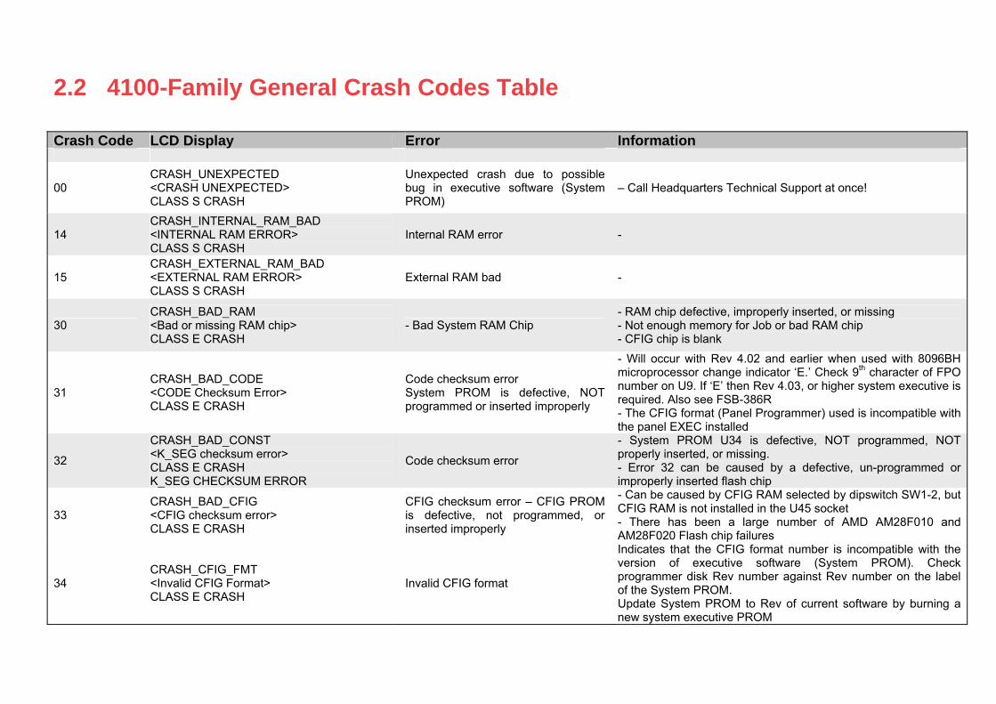
2.2 4100-Family General Crash Codes Table Crash Code LCD Display Error Information
00 CRASH_UNEXPECTED <CRASH UNEXPECTED> CLASS S CRASH
Unexpected crash due to possible bug in executive software (System PROM)
– Call Headquarters Technical Support at once!
14 CRASH_INTERNAL_RAM_BAD <INTERNAL RAM ERROR> CLASS S CRASH
Internal RAM error -
15 CRASH_EXTERNAL_RAM_BAD <EXTERNAL RAM ERROR> CLASS S CRASH
External RAM bad -
30 CRASH_BAD_RAM <Bad or missing RAM chip> CLASS E CRASH
- Bad System RAM Chip - RAM chip defective, improperly inserted, or missing - Not enough memory for Job or bad RAM chip - CFIG chip is blank
31 CRASH_BAD_CODE <CODE Checksum Error> CLASS E CRASH
Code checksum error System PROM is defective, NOT programmed or inserted improperly
- Will occur with Rev 4.02 and earlier when used with 8096BH microprocessor change indicator ‘E.’ Check 9th character of FPO number on U9. If ‘E’ then Rev 4.03, or higher system executive is required. Also see FSB-386R - The CFIG format (Panel Programmer) used is incompatible with the panel EXEC installed
32
CRASH_BAD_CONST <K_SEG checksum error> CLASS E CRASH K_SEG CHECKSUM ERROR
Code checksum error
- System PROM U34 is defective, NOT programmed, NOT properly inserted, or missing. - Error 32 can be caused by a defective, un-programmed or improperly inserted flash chip
33 CRASH_BAD_CFIG <CFIG checksum error> CLASS E CRASH
CFIG checksum error – CFIG PROM is defective, not programmed, or inserted improperly
- Can be caused by CFIG RAM selected by dipswitch SW1-2, but CFIG RAM is not installed in the U45 socket - There has been a large number of AMD AM28F010 and AM28F020 Flash chip failures
34 CRASH_CFIG_FMT <Invalid CFIG Format> CLASS E CRASH
Invalid CFIG format
Indicates that the CFIG format number is incompatible with the version of executive software (System PROM). Check programmer disk Rev number against Rev number on the label of the System PROM. Update System PROM to Rev of current software by burning a new system executive PROM
- 33 -
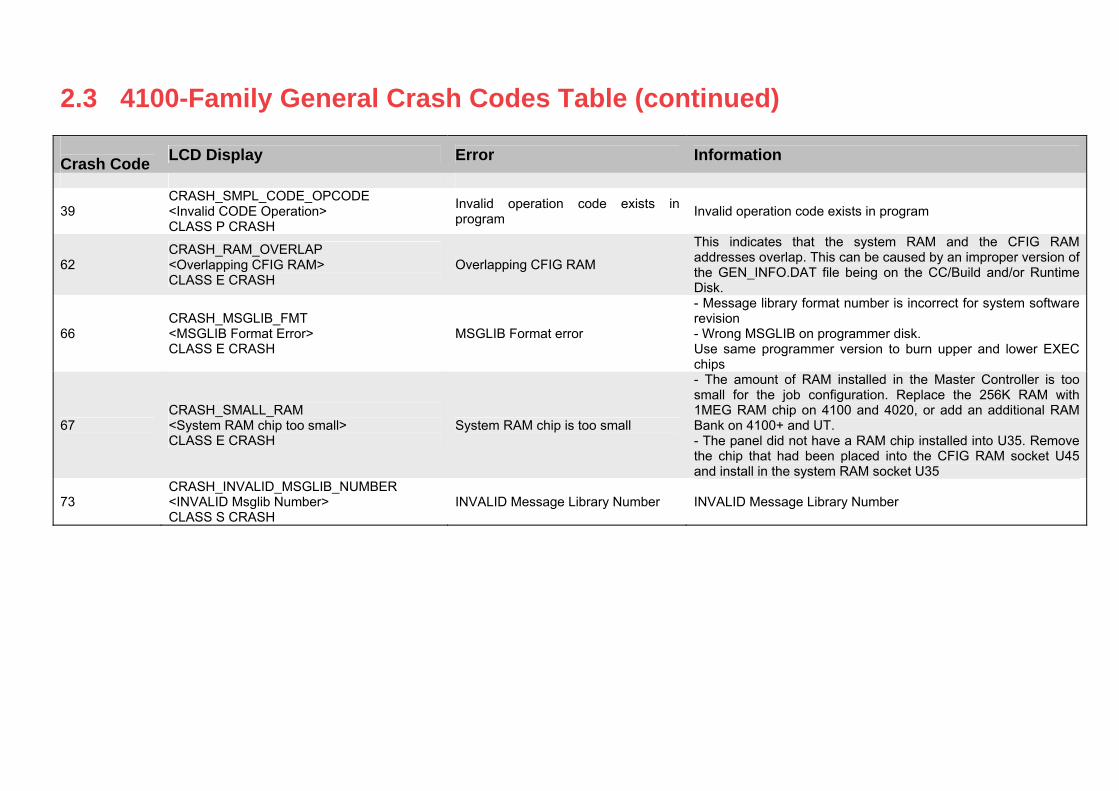
2.3 4100-Family General Crash Codes Table (continued) Crash Code LCD Display Error Information
39 CRASH_SMPL_CODE_OPCODE <Invalid CODE Operation> CLASS P CRASH
Invalid operation code exists in program Invalid operation code exists in program
62 CRASH_RAM_OVERLAP <Overlapping CFIG RAM> CLASS E CRASH
Overlapping CFIG RAM
This indicates that the system RAM and the CFIG RAM addresses overlap. This can be caused by an improper version of the GEN_INFO.DAT file being on the CC/Build and/or Runtime Disk.
66 CRASH_MSGLIB_FMT <MSGLIB Format Error> CLASS E CRASH
MSGLIB Format error
- Message library format number is incorrect for system software revision - Wrong MSGLIB on programmer disk. Use same programmer version to burn upper and lower EXEC chips
67 CRASH_SMALL_RAM <System RAM chip too small> CLASS E CRASH
System RAM chip is too small
- The amount of RAM installed in the Master Controller is too small for the job configuration. Replace the 256K RAM with 1MEG RAM chip on 4100 and 4020, or add an additional RAM Bank on 4100+ and UT. - The panel did not have a RAM chip installed into U35. Remove the chip that had been placed into the CFIG RAM socket U45 and install in the system RAM socket U35
73 CRASH_INVALID_MSGLIB_NUMBER <INVALID Msglib Number> CLASS S CRASH
INVALID Message Library Number INVALID Message Library Number

- 34 - 34 of 72 SIMPLEX Fault Assistance Guide RevA
29 April 2009
TTTHHHIIISSS PPPAAAGGGEEE HHHAAASSS BBBEEEEEENNN LLLEEEFFFTTT BBBLLLAAANNNKKK IIINNNTTTEEENNNTTTIIIOOONNNAAALLLLLLYYY
- 35 - 35 of 72 SIMPLEX Fault Assistance Guide RevA
29 April 2009
3.0 Identifying Faults on the IMS & Network
- 36 - 36 of 72 SIMPLEX Fault Assistance Guide RevA
29 April 2009
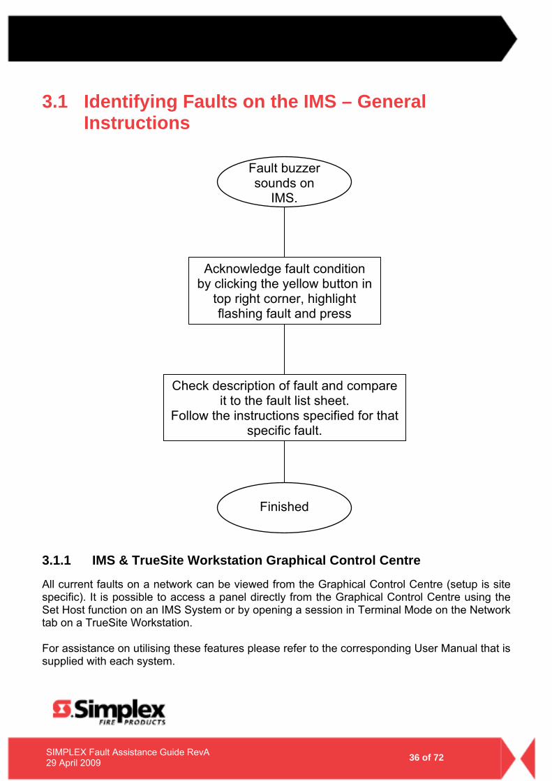
3.1 Identifying Faults on the IMS – General Instructions
3.1.1 IMS & TrueSite Workstation Graphical Control Centre
All current faults on a network can be viewed from the Graphical Control Centre (setup is site specific). It is possible to access a panel directly from the Graphical Control Centre using the Set Host function on an IMS System or by opening a session in Terminal Mode on the Network tab on a TrueSite Workstation. For assistance on utilising these features please refer to the corresponding User Manual that is supplied with each system.
Acknowledge fault condition by clicking the yellow button in
top right corner, highlight flashing fault and press
Check description of fault and compare it to the fault list sheet.
Follow the instructions specified for that specific fault.
Finished
Fault buzzer sounds on
IMS.
- 37 - 37 of 72 SIMPLEX Fault Assistance Guide RevA
29 April 2009
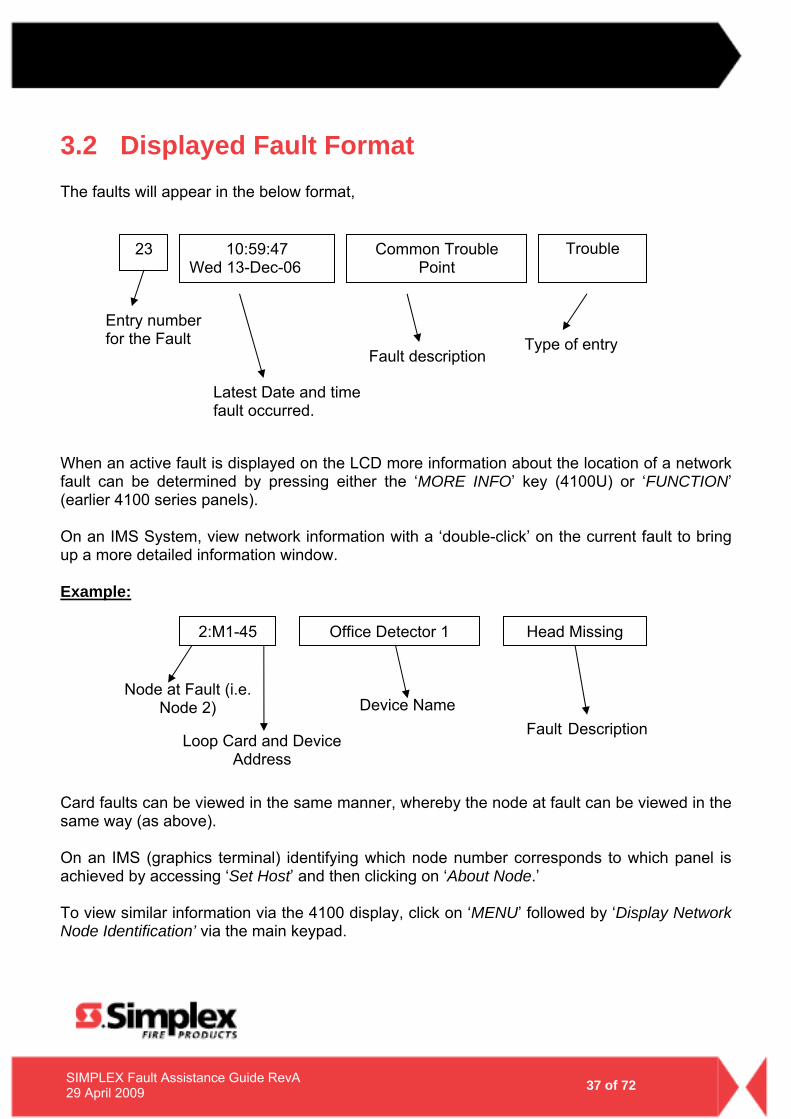
3.2 Displayed Fault Format The faults will appear in the below format,
When an active fault is displayed on the LCD more information about the location of a network fault can be determined by pressing either the ‘MORE INFO’ key (4100U) or ‘FUNCTION’ (earlier 4100 series panels). On an IMS System, view network information with a ‘double-click’ on the current fault to bring up a more detailed information window. Example:
Card faults can be viewed in the same manner, whereby the node at fault can be viewed in the same way (as above). On an IMS (graphics terminal) identifying which node number corresponds to which panel is achieved by accessing ‘Set Host’ and then clicking on ‘About Node.’ To view similar information via the 4100 display, click on ‘MENU’ followed by ‘Display Network Node Identification’ via the main keypad.
23 10:59:47 Wed 13-Dec-06
Common Trouble Point
Trouble
Entry number for the Fault
Latest Date and time fault occurred.
Fault description Type of entry
Office Detector 12:M1-45 Head Missing
Node at Fault (i.e. Node 2)
Loop Card and Device Address
Device Name Fault Description
- 38 - 38 of 72 SIMPLEX Fault Assistance Guide RevA
29 April 2009
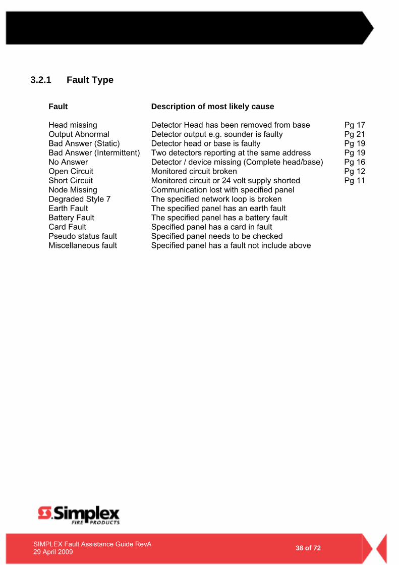
3.2.1 Fault Type
Fault Description of most likely cause Head missing Detector Head has been removed from base Pg 17 Output Abnormal Detector output e.g. sounder is faulty Pg 21 Bad Answer (Static) Detector head or base is faulty Pg 19 Bad Answer (Intermittent) Two detectors reporting at the same address Pg 19 No Answer Detector / device missing (Complete head/base) Pg 16 Open Circuit Monitored circuit broken Pg 12 Short Circuit Monitored circuit or 24 volt supply shorted Pg 11 Node Missing Communication lost with specified panel Degraded Style 7 The specified network loop is broken Earth Fault The specified panel has an earth fault Battery Fault The specified panel has a battery fault Card Fault Specified panel has a card in fault Pseudo status fault Specified panel needs to be checked Miscellaneous fault Specified panel has a fault not include above
- 39 - 39 of 72 SIMPLEX Fault Assistance Guide RevA
29 April 2009
3.3 Common Network Faults 3.3.1 Common Trouble Point for Node
A fault has occurred within a device, or card (etc) that is flagging the Common Trouble Point for that Node around the network. Only by accessing the Node encompassing the fault (or Graphics Control Centre), will more specific fault information be available.
3.3.2 Card Trouble for Node
This fault indicates that there are one or more faults associated with a card in the listed Network Node. For further diagnosis of the fault, you will need to access the Node encompassing the fault.
3.3.3 Network Operating in Degraded Style 7
Style 7 networks are a continuous ring topology. If the network ring has a break or incorrectly terminated cable pair, then the network cards see this as an open circuit and will display a ‘Degraded Style-7’ fault
3.3.4 Network Initialization Incomplete
During the network boot-up sequence, there are panel/s that have not successfully initialized. May require a full network reboot (global warm restart which can be done remotely on some networked systems by access the MFIP)
3.3.5 Node Missing/Failed
The node from which you are viewing the fault cannot communicate successfully to the node/s listed
3.3.6 System Pseudo Status for Node
This fault is similar to the Common Trouble Point for Node as there is a System Pseudo (or virtual point) that is in an abnormal state on the listed Node. Accessing the Node encompassing the fault may provide more specific information.
3.3.7 Version Mismatch
The configurations do not match between at least two nodes. Please Contact your local Simplex Fire Service Provider for Assistance

- 40 - 40 of 72 SIMPLEX Fault Assistance Guide RevA
29 April 2009
TTTHHHIIISSS PPPAAAGGGEEE HHHAAASSS BBBEEEEEENNN LLLEEEFFFTTT BBBLLLAAANNNKKK IIINNNTTTEEENNNTTTIIIOOONNNAAALLLLLLYYY

- 41 - 41 of 72 SIMPLEX Fault Assistance Guide RevA
29 April 2009
4.0 Identifying F3200 Faults
- 42 - 42 of 72 SIMPLEX Fault Assistance Guide RevA
29 April 2009
4.1 Recall System Faults
4.1.1 Function
The Recall System Faults function allows viewing on the LCD the current causes of a "SYSTEM FAULT" indication. It also displays the status of any RZDU (Remote Zone Display Unit) that has an off-normal condition, including those which do not cause System Fault
4.1.2 Operating Sequence
For both networked and non-networked systems, from the base display, press:
OR If there are no system faults, a brief message is displayed saying so, and the LCD reverts to the base display. If a system fault exists, the LCD will display it. To view the next fault, press: To view the previous fault, press:
- 43 - 43 of 72 SIMPLEX Fault Assistance Guide RevA
29 April 2009
4.2 List of System Faults – Non-Networked The complete list of faults which can be displayed by a system fault recall is as follows:
1. Mains fail When mains fail appears in a system fault recall it indicates that mains is currently failed. When mains have failed continuously for 8 hours a system fault may be generated depending on programming.
2. EEPROM database checksum error
The panel is in-operational if this fault is present.
3. EEPROM database version error This fault condition means that the EEPROM database checksum is correct but the database is an old version with a format which cannot be used. All circuit processing is disabled when this fault is present and the panel is in-operational.
4. Module configuration mismatch
This fault occurs when the number of Zone or Relay Modules installed does not match the programmed number of modules required to be present. The bottom line states processing is enabled or disabled. On detection of a module mismatch processing is disabled and the panel is not operational. A technician can temporarily assign a new configuration so that processing can be re-enabled and use only those modules that are present. This System fault will remain until the correct number of modules is installed and verified as operating correctly.
5. Keypad disconnected
Processing of circuit inputs and alarms continues.
6. LED display board fault There is a fault with a zone or relay LED display board. This can occur if the wrong number of display boards is installed.
7. LCD display fault
A fault has occurred with the 80 character LCD. This can occur at startup or during an LCD test.
8. EPROM CRC error
A checksum calculation of EPROM memory has failed. This can occur during System and Auto Test.
9. RAM write read fault
A write read test of main RAM has failed. This can occur during System and Auto Test.
- 44 - 44 of 72 SIMPLEX Fault Assistance Guide RevA
29 April 2009
10. Charger high/low/normal Raw value = high/low/normal
This message indicates the battery charger voltage is high or low. When this fault is viewed in the system fault recall, the display will show the current state of the charger as high, low, or normal, which may be useful for adjusting the charger potentiometer. A charger low condition will not produce a system fault until 30 minutes after any battery test, but will still appear in a system fault recall during this time. During a battery test a charger low condition (for the raw value) will be displayed in a system fault recall as the charger is inhibited, but this is not a system fault.
11. Fuse blown
Check for a blown fuse, and replace with a fuse of the same amperage rating
12. Clock chip RAM fault Clock chip RAM is used to store all the isolate data (zone and relay isolate status, etc) plus temporary "board present" assignments. The isolate data and board present data is read from clock chip RAM at startup and this fault means the clock chip RAM has not saved the data correctly and will probably not be read correctly at startup. Try isolating and de-isolating something (e.g. bells) to get the controller to retry writing/reading this RAM.
13. EEPROM write fail
This fault will occur if a failure occurs when writing to EEPROM database memory during program mode.
14. All MAF zones isolated
This fault will occur if all zones (mapped to MAF) are isolated. This can be inhibited with an option in programming, but doing so contravenes AS1603.4.
15. Supply failed
This fault means that both mains have failed and the battery voltage has fallen to 21 volts or below. The standby relay is de-energised and all processing of circuit inputs stops.
16. Output logic exec error nn
An error has occurred with output logic execution. The error number nn has the following meaning:
- 45 - 45 of 72 SIMPLEX Fault Assistance Guide RevA
29 April 2009
NOTE: The software produces the following error messages from a series of built-in
checks which are performed during the operating of the FIP outputs. It is highly unlikely that such errors will occur. If one does, the operator should inform the service company and have them check it.
• “No equations have been found but some were expected”. This
indicates a conflict in the information stored in the EEPROM database.
• Invalid Opcode - An invalid token has been encountered in an equation.
• Range error - This occurs when an out of range value is found such as a timer number greater than 64 or an ancillary relay number greater than 3.
• Stack error - The execution stack in the RAM has overflowed or under-flowed.
• Link error - An invalid value has been found in a link field in an equation.
• Invalid MAF output - This indicates a conflict in information stored in the EEPROM database. An equation has been found to control an ancillary or MAF relay but was not expected.
• NA (New Alarm) function RAM limit exceeded - This indicates too many NA functions have been used in the programming of Output Logic functions.
• Netvar SID not present - This error occurs if a network variable in the output logic specifies a SID which is not present in the SID list of this panel. Every SID for which Netvars are to be accessed must be entered into the SID list of this panel.
• Zone command range error - An equation to isolate/de-isolate or reset a zone or range of zones had an invalid zone number.
17. System/Auto Test circuit test fail A circuit test failed during system or Auto Test or an unexpected fault or alarm occurred during the test. The Brigade fault relay is turned on when this fault is present. The fault will be cleared by a successful system or Auto Test. Isolating the faulty circuit & performing a system test should allow the test to pass & clear the fault.
18. Shift register bus fault This error indicates a fault with the bus connecting the Controller with the MAF/PSU, zone modules and relay modules. It may be caused by a break or short in the flat ribbon cable (e.g. bd unplugged), by temporary noise, or by a circuit board fault. NOTE: When this fault occurs all processing of inputs stops until the fault clears. If
the fault does clear, processing of inputs resumes automatically.
- 46 - 46 of 72 SIMPLEX Fault Assistance Guide RevA
29 April 2009
19. RZDU x This displays the current status of any RZDU which has an off-normal condition.
20. Net msg discard This occurs only with network systems. The local system discarded a message that was repeatedly sent to another device on the network that did not acknowledge it. To allow other messages to be sent on the network, the unacknowledged msg was discarded. This should occur only in cases of extreme network loading, if the system addressed does not exist or is off line, or if network cables are broken.
21. Net port hw fault This indicates a hardware fault with the serial port interfacing to the network. Call the service company.
22. Clock crystal Timebase check fail This error message occurs only at startup and indicates the frequency of the clock chip on the Controller is out of tolerance to the microprocessor. The Controller will restart and try the test again.
23. Clock register write read fail A test of the Controller time/date clock registers has failed. The Controller will restart and try the test again.
24. Clock chip RAM write read fail A test of the Controller’s clock RAM has failed. The Controller will re-start and try the test again.
25. Shift reg clocking fault This is the same fault as “Shift register bus fault” above. However, this fault occurs only at startup or on exit from programming mode when the panel is trying to determine what modules are present.
26. Battery is low This message indicates the battery voltage is low. When PSU faults are inhibited for 24 hours, this message will still appear in a system fault recall if the voltage is low even though it is not creating a system fault.
27. Battery connection fail This message indicates the battery is not connected, but may occur with the battery connected if the battery is faulty or has a low charge. When PSU faults are inhibited for 24 hours, this message will still appear in a system fault recall if the battery appears to be not connected even though it is not creating a system fault.
28. Battery capacity low This message indicates an automatic battery test failed, i.e. the battery has a low charge.
- 47 - 47 of 72 SIMPLEX Fault Assistance Guide RevA
29 April 2009
4.3 Glossary of Abbreviations A/C : Air Conditioning ac : Alternating Current AEOL : Active End of Line AHr : Ampere Hour ANC 1 : Ancillary Relay 1 ASE : Alarm Signaling Equipment AZC : Alarm Zone Circuit, or Detection Zone AZF : Alarm Zone Facility, or Group (AS1603.4 terminology) AVF : Alarm Verification Facility, or Check Alarm Bd : Board CIE : Control & Indicating Equipment Char : Character Cct : Circuit COM : COMMON relay contact dc : Direct current EB : External Bell EEPROM : Electrically Erasable Programmable Read Only Memory ELV : Extra Low Voltage EOL : End Of Line (device) EOLR : End of Line Resistor Expn : Expansion E2 : Electrically Erasable Programmable Read Only Memory FF : Firefighter Facility (part of Display/Keyboard) FIP : Fire Indicator Panel FRC : Flat Ribbon Cable I/O : Input/Output LCD : Liquid Crystal Display LED : Light Emitting Diode MAF : Master Alarm Facility Max : Maximum Min : Minimum MCP : Manual Call Point (Break Glass Switch) MOV : Metal Oxide Varistor (Used for electrical Surge Protection) msec : Millisecond NC : Normally Closed NDU : Network Display Unit NO : Normally Open No : Number Nom : Nominal PC : Personal Computer (small computer) PCB : Printed Circuit Board PSU : Power Supply Unit PTC : Positive Temperature Co-efficient (Thermistor) R1 : Module Relay Number 1 (program abbreviation) RL1 : Module Relay Number 1 (text abbreviation)
- 48 - 48 of 72 SIMPLEX Fault Assistance Guide RevA
29 April 2009
RAD : Return Air Duct (Air Conditioning Plant) RDU : Remote Display Unit RMS : Root Mean Square Reqd : Required RTC : Real Time Clock SAD : Supply Air Duct (Air Conditioning Plant) SID : System Identification Number (Network device) sq mm : square millimetre T1 : Programmable Timer Number 1 (program abbreviation) Tmnl : Terminal V1 : Programmable Variable Number 1 VA : Volts Amperes VB : Battery Backed Voltage VNB : Non Battery Backed Voltage +VBF : Fused Battery-Backed Voltage +VNBF : Fused Non-Battery-Backed Voltage WS : Warning System Z1 : Zone Number 1 (program abbreviation) Zn1 : Zone Number 1 (text abbreviation) 8RM : 8 Relay Module 8ZM : 8 Zone Module

- 49 - 49 of 72 SIMPLEX Fault Assistance Guide RevA
29 April 2009
TTTHHHIIISSS PPPAAAGGGEEE HHHAAASSS BBBEEEEEENNN LLLEEEFFFTTT BBBLLLAAANNNKKK IIINNNTTTEEENNNTTTIIIOOONNNAAALLLLLLYYY

- 50 - 50 of 72 SIMPLEX Fault Assistance Guide RevA
29 April 2009
5.0 Identifying faults on a QE90
- 51 - 51 of 72 SIMPLEX Fault Assistance Guide RevA
29 April 2009
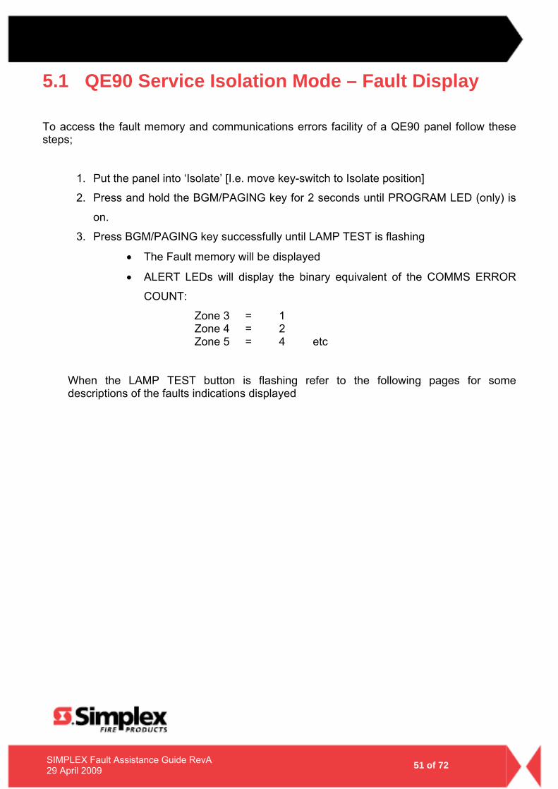
5.1 QE90 Service Isolation Mode – Fault Display
To access the fault memory and communications errors facility of a QE90 panel follow these steps;
1. Put the panel into ‘Isolate’ [I.e. move key-switch to Isolate position]
2. Press and hold the BGM/PAGING key for 2 seconds until PROGRAM LED (only) is
on.
3. Press BGM/PAGING key successfully until LAMP TEST is flashing
• The Fault memory will be displayed
• ALERT LEDs will display the binary equivalent of the COMMS ERROR
COUNT:
Zone 3 = 1 Zone 4 = 2 Zone 5 = 4 etc
When the LAMP TEST button is flashing refer to the following pages for some descriptions of the faults indications displayed
- 52 -
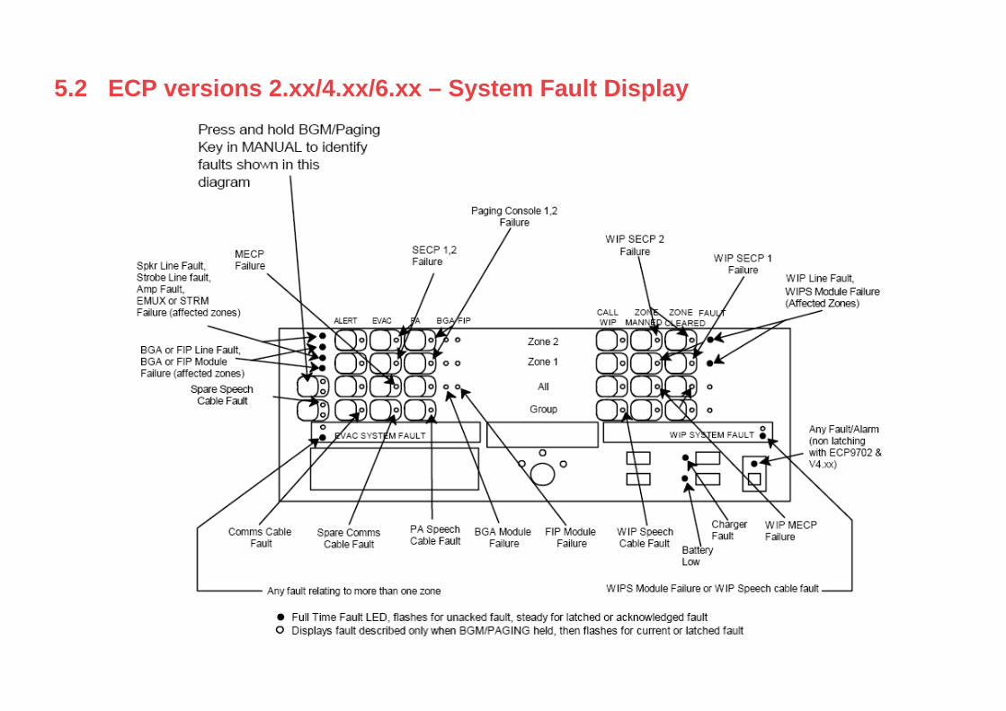
5.2 ECP versions 2.xx/4.xx/6.xx – System Fault Display
- 53 - 53 of 72 SIMPLEX Fault Assistance Guide RevA
29 April 2009
5.3 Audio Line Fault
5.3.1 Speaker Line Fault/Amp Fault
• Check EOL resistor (56k) • If ok, swap speaker lines to a different Zone (on amp)
Test to see if the fault has followed
• IF YES – the fault could be in the field (wiring, devices) • IF NO – the fault is likely to be in the transformers/amplifiers
NOTE: A good way to test where a fault is located within the panel is swapping identical
components over and testing to see if the fault follows the device. This allows you to eliminate if the fault is located on a device/card within the panel or out in the field wiring/devices.
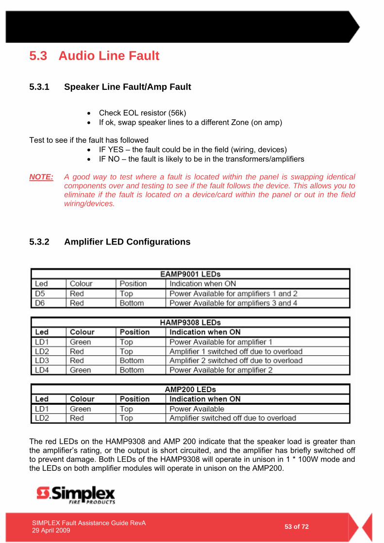
5.3.2 Amplifier LED Configurations
The red LEDs on the HAMP9308 and AMP 200 indicate that the speaker load is greater than the amplifier’s rating, or the output is short circuited, and the amplifier has briefly switched off to prevent damage. Both LEDs of the HAMP9308 will operate in unison in 1 * 100W mode and the LEDs on both amplifier modules will operate in unison on the AMP200.
- 54 - 54 of 72 SIMPLEX Fault Assistance Guide RevA
29 April 2009
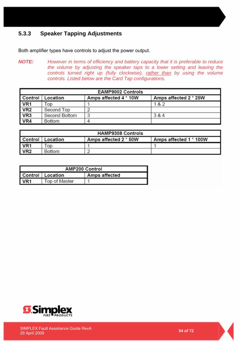
5.3.3 Speaker Tapping Adjustments
Both amplifier types have controls to adjust the power output. NOTE: However in terms of efficiency and battery capacity that it is preferable to reduce
the volume by adjusting the speaker taps to a lower setting and leaving the controls turned right up (fully clockwise), rather than by using the volume controls. Listed below are the Card Tap configurations.
- 55 - 55 of 72 SIMPLEX Fault Assistance Guide RevA
29 April 2009
5.4 Strobe Line Fault
• Check EOL resistor (56k) • If ok, swap speaker lines to a different Zone (on amp)
Test to see if the fault has followed
• IF YES – the fault could be in the field (wiring, devices) • IF NO – the fault is likely to be in the transformers/amplifiers
NOTE: A good way to test where a fault is located within the panel is swapping identical
components over and testing to see if the fault follows the device. This allows you to eliminate if the fault is located on a device/card within the panel or out in the field wiring/devices.
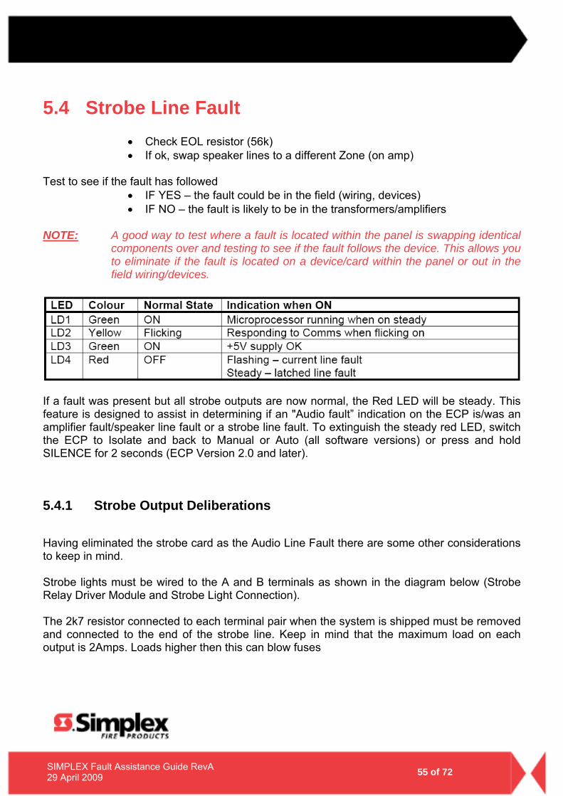
If a fault was present but all strobe outputs are now normal, the Red LED will be steady. This feature is designed to assist in determining if an "Audio fault” indication on the ECP is/was an amplifier fault/speaker line fault or a strobe line fault. To extinguish the steady red LED, switch the ECP to Isolate and back to Manual or Auto (all software versions) or press and hold SILENCE for 2 seconds (ECP Version 2.0 and later).
5.4.1 Strobe Output Deliberations
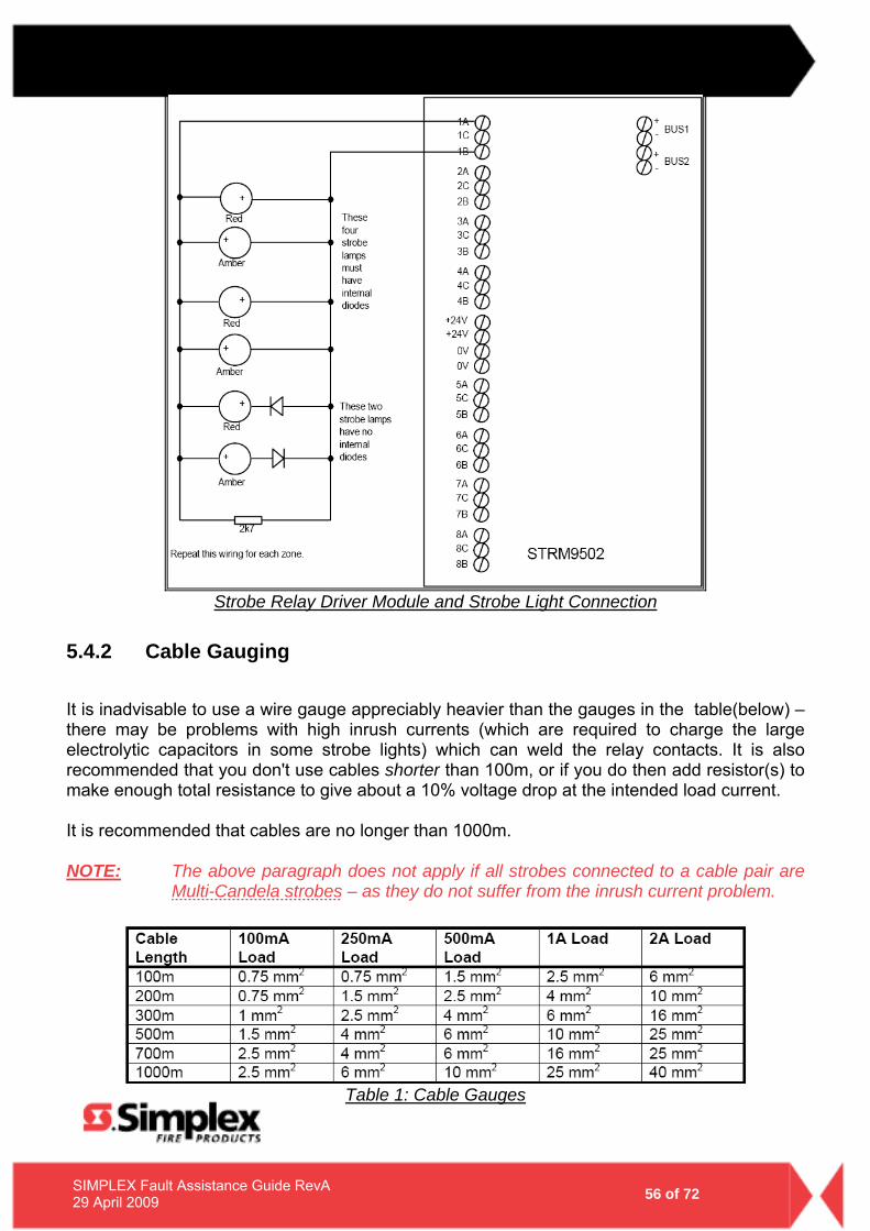
Having eliminated the strobe card as the Audio Line Fault there are some other considerations to keep in mind. Strobe lights must be wired to the A and B terminals as shown in the diagram below (Strobe Relay Driver Module and Strobe Light Connection). The 2k7 resistor connected to each terminal pair when the system is shipped must be removed and connected to the end of the strobe line. Keep in mind that the maximum load on each output is 2Amps. Loads higher then this can blow fuses
- 56 - 56 of 72 SIMPLEX Fault Assistance Guide RevA
29 April 2009
Strobe Relay Driver Module and Strobe Light Connection
5.4.2 Cable Gauging
It is inadvisable to use a wire gauge appreciably heavier than the gauges in the table(below) – there may be problems with high inrush currents (which are required to charge the large electrolytic capacitors in some strobe lights) which can weld the relay contacts. It is also recommended that you don't use cables shorter than 100m, or if you do then add resistor(s) to make enough total resistance to give about a 10% voltage drop at the intended load current. It is recommended that cables are no longer than 1000m. NOTE: The above paragraph does not apply if all strobes connected to a cable pair are
Multi-Candela strobes – as they do not suffer from the inrush current problem.
Table 1: Cable Gauges
- 57 - 57 of 72 SIMPLEX Fault Assistance Guide RevA
29 April 2009
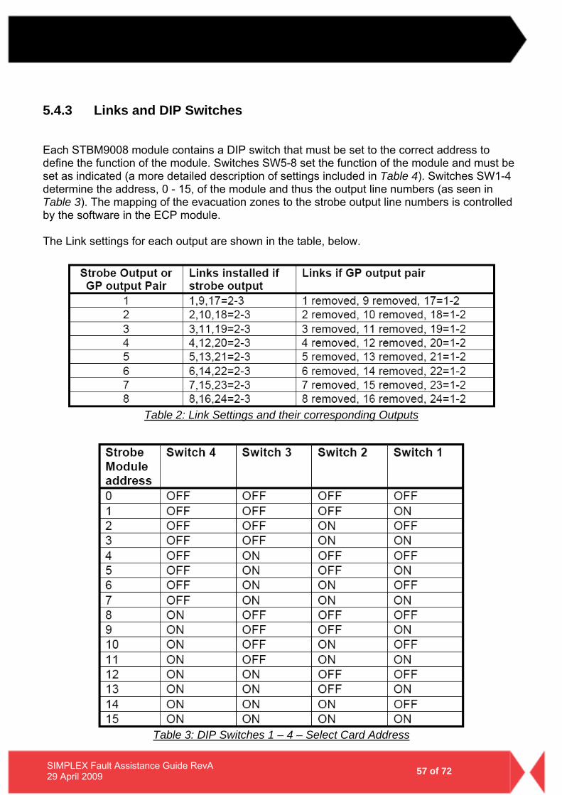
5.4.3 Links and DIP Switches
Each STBM9008 module contains a DIP switch that must be set to the correct address to define the function of the module. Switches SW5-8 set the function of the module and must be set as indicated (a more detailed description of settings included in Table 4). Switches SW1-4 determine the address, 0 - 15, of the module and thus the output line numbers (as seen in Table 3). The mapping of the evacuation zones to the strobe output line numbers is controlled by the software in the ECP module. The Link settings for each output are shown in the table, below.
Table 2: Link Settings and their corresponding Outputs
Table 3: DIP Switches 1 – 4 – Select Card Address
- 58 - 58 of 72 SIMPLEX Fault Assistance Guide RevA
29 April 2009
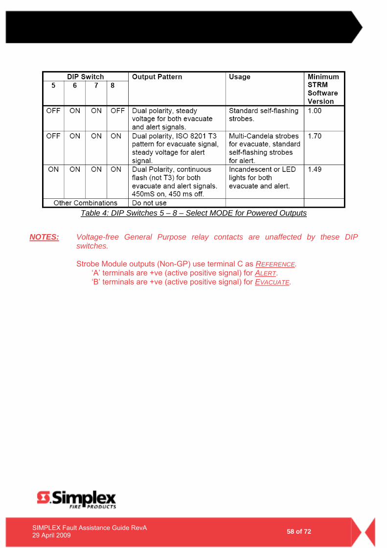
Table 4: DIP Switches 5 – 8 – Select MODE for Powered Outputs
NOTES: Voltage-free General Purpose relay contacts are unaffected by these DIP
switches.
Strobe Module outputs (Non-GP) use terminal C as REFERENCE. ‘A’ terminals are +ve (active positive signal) for ALERT. ‘B’ terminals are +ve (active positive signal) for EVACUATE.
- 59 - 59 of 72 SIMPLEX Fault Assistance Guide RevA
29 April 2009
5.4.4 STBM9008 Board Installation
To install the STBM9008 Module, perform the following steps: STEP 1: Install the STBM9008 board into the DIN rail housing and install the
unit on the DIN rail. STEP 2: Isolate power to the SYSTEM by Switching OFF ALL the DC circuit
breakers on the power supply unit. STEP 3: Install all the cable connections to the STBM9008 module and ensure
that the DIP switch has been set to the correct settings. STEP 4: Switch on the DC circuit breakers and check that the system
functions correctly.
- 60 - 60 of 72 SIMPLEX Fault Assistance Guide RevA
29 April 2009
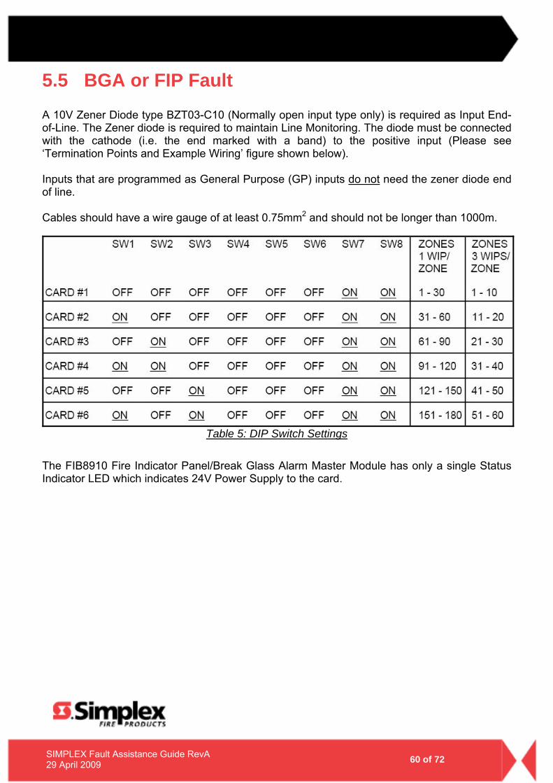
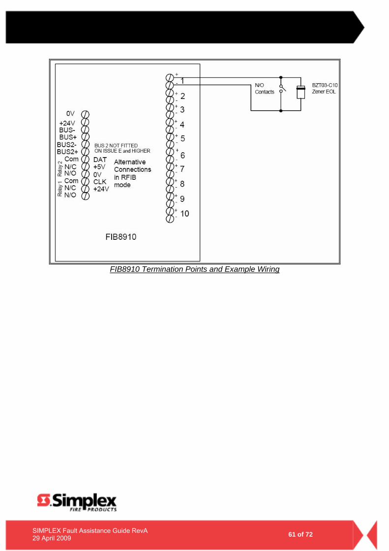
5.5 BGA or FIP Fault A 10V Zener Diode type BZT03-C10 (Normally open input type only) is required as Input End-of-Line. The Zener diode is required to maintain Line Monitoring. The diode must be connected with the cathode (i.e. the end marked with a band) to the positive input (Please see ‘Termination Points and Example Wiring’ figure shown below). Inputs that are programmed as General Purpose (GP) inputs do not need the zener diode end of line. Cables should have a wire gauge of at least 0.75mm2 and should not be longer than 1000m.
Table 5: DIP Switch Settings
The FIB8910 Fire Indicator Panel/Break Glass Alarm Master Module has only a single Status Indicator LED which indicates 24V Power Supply to the card.
- 61 - 61 of 72 SIMPLEX Fault Assistance Guide RevA
29 April 2009
FIB8910 Termination Points and Example Wiring
- 62 - 62 of 72 SIMPLEX Fault Assistance Guide RevA
29 April 2009
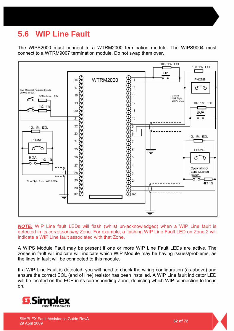
5.6 WIP Line Fault The WIPS2000 must connect to a WTRM2000 termination module. The WIPS9004 must connect to a WTRM9007 termination module. Do not swap them over.
NOTE: WIP Line fault LEDs will flash (whilst un-acknowledged) when a WIP Line fault is detected in its corresponding Zone. For example, a flashing WIP Line Fault LED on Zone 2 will indicate a WIP Line fault associated with that Zone. A WIPS Module Fault may be present if one or more WIP Line Fault LEDs are active. The zones in fault will indicate will indicate which WIP Module may be having issues/problems, as the lines in fault will be connected to this module. If a WIP Line Fault is detected, you will need to check the wiring configuration (as above) and ensure the correct EOL (end of line) resistor has been installed. A WIP Line fault indicator LED will be located on the ECP in its corresponding Zone, depicting which WIP connection to focus on.
- 63 - 63 of 72 SIMPLEX Fault Assistance Guide RevA
29 April 2009
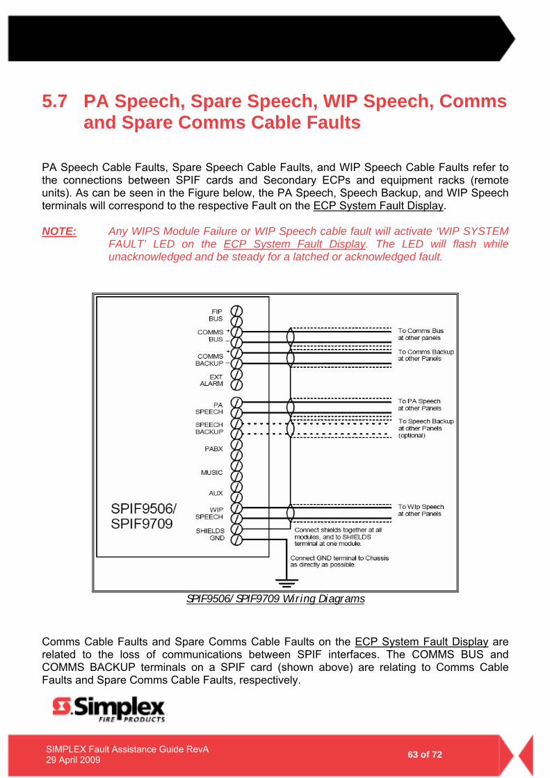
5.7 PA Speech, Spare Speech, WIP Speech, Comms and Spare Comms Cable Faults
PA Speech Cable Faults, Spare Speech Cable Faults, and WIP Speech Cable Faults refer to the connections between SPIF cards and Secondary ECPs and equipment racks (remote units). As can be seen in the Figure below, the PA Speech, Speech Backup, and WIP Speech terminals will correspond to the respective Fault on the ECP System Fault Display. NOTE: Any WIPS Module Failure or WIP Speech cable fault will activate ‘WIP SYSTEM
FAULT’ LED on the ECP System Fault Display. The LED will flash while unacknowledged and be steady for a latched or acknowledged fault.
SPIF9506/SPIF9709 Wiring Diagrams
Comms Cable Faults and Spare Comms Cable Faults on the ECP System Fault Display are related to the loss of communications between SPIF interfaces. The COMMS BUS and COMMS BACKUP terminals on a SPIF card (shown above) are relating to Comms Cable Faults and Spare Comms Cable Faults, respectively.
- 64 - 64 of 72 SIMPLEX Fault Assistance Guide RevA
29 April 2009
5.8 ECP Failures
5.8.1 MECP and SECP Failure
A MECP failure will be present on any SECP when communications is lost and/or the panel has failed to activate correctly. In a similar fashion, an SECP failure will be present when communications is lost and/or the panel has failed to activate correctly.
5.8.2 WIP MECP and SECP Failure
A WIP MECP failure will be present on any SECP when a WIP Line fault or WIPS Module failure is detected on the MECP. In a similar fashion, any WIP SECP failure will be present on any SECP when a WIP Line fault or WIPS Module failure is present on the SECP/s.
5.8.3 Paging Console Failure
A paging console failure will be observed when a loss of communication to the Paging console/s is discovered.
- 65 -
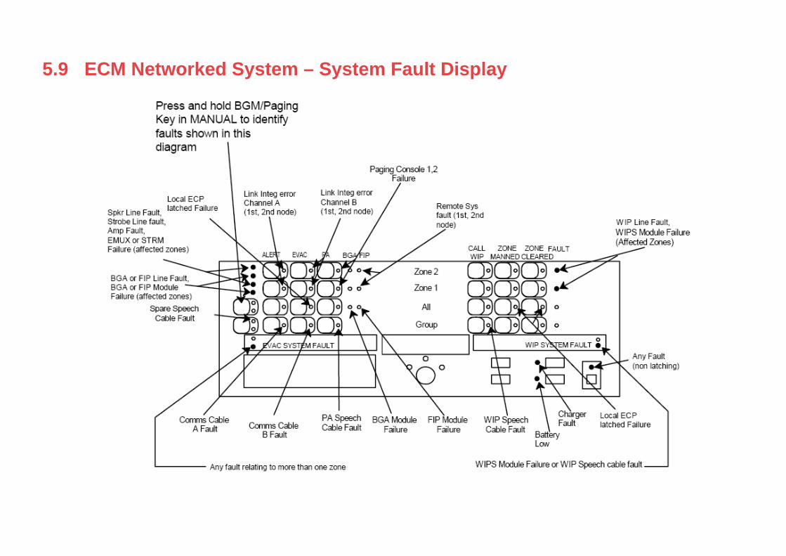
5.9 ECM Networked System – System Fault Display
- 66 - 66 of 72 SIMPLEX Fault Assistance Guide RevA
29 April 2009
5.10 ECM Networked Systems If you are having issues with an ECM Network and are unable to diagnose a fault/trouble – please contact your local Simplex® Personnel who will be able to assist.
- 67 -
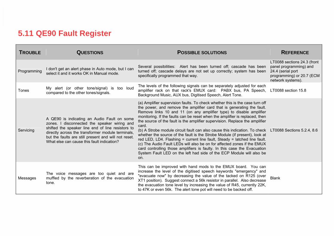
5.11 QE90 Fault Register
TROUBLE QUESTIONS POSSIBLE SOLUTIONS REFERENCE
Programming I don't get an alert phase in Auto mode, but I can select it and it works OK in Manual mode.
Several possibilities: Alert has been turned off; cascade has been turned off; cascade delays are not set up correctly; system has been specifically programmed that way.
LT0088 sections 24.3 (front panel programming) and 24.4 (serial port programming) or 20.7 (ECM network systems).
Tones My alert (or other tone/signal) is too loud compared to the other tones/signals.
The levels of the following signals can be separately adjusted for each amplifier rack on that rack's EMUX card: PABX bus, PA Speech, Background Music, AUX bus, Digitised Speech, Alert Tone.
LT0088 section 15.8
Servicing
A QE90 is indicating an Audio Fault on some zones. I disconnected the speaker wiring and shifted the speaker line end of line resistors to directly across the transformer module terminals, but the faults are still present and will not reset. What else can cause this fault indication?
(a) Amplifier supervision faults. To check whether this is the case turn off the power, and remove the amplifier card that is generating the fault. Remove links 10 and 11 (on any amplifier type) to disable amplifier monitoring. If the faults can be reset when the amplifier is replaced, then the source of the fault is the amplifier supervision. Replace the amplifier card. (b) A Strobe module circuit fault can also cause this indication. To check whether the source of the fault is the Strobe Module (if present), look at red LED, LD4. Flashing = current line fault, Steady = latched line fault. (c) The Audio Fault LEDs will also be on for affected zones if the EMUX card controlling those amplifiers is faulty. In this case the Evacuation System Fault LED on the left had side of the ECP Module will also be on.
LT0088 Sections 5.2.4, 8.6
Messages The voice messages are too quiet and are muffled by the reverberation of the evacuation tone.
This can be improved with hand mods to the EMUX board. You can increase the level of the digitised speech keywords "emergency" and "evacuate now" by decreasing the value of the tacked on R125 (over XT1 position). Suggest connect a 56k resistor in parallel. Also decrease the evacuation tone level by increasing the value of R45, currently 22K, to 47K or even 56k. The alert tone pot will need to be backed off.
Blank
- 68 -
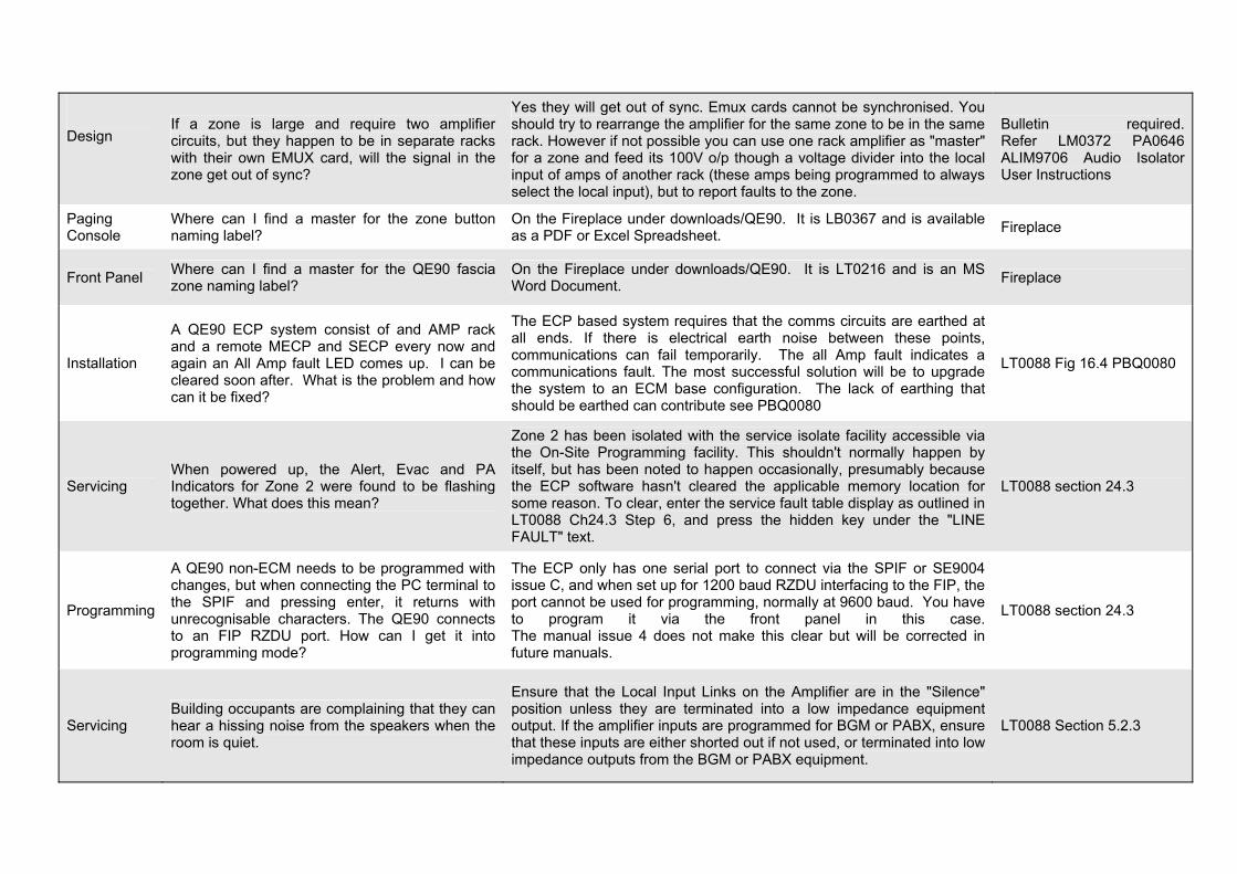
Design
If a zone is large and require two amplifier circuits, but they happen to be in separate racks with their own EMUX card, will the signal in the zone get out of sync?
Yes they will get out of sync. Emux cards cannot be synchronised. You should try to rearrange the amplifier for the same zone to be in the same rack. However if not possible you can use one rack amplifier as "master" for a zone and feed its 100V o/p though a voltage divider into the local input of amps of another rack (these amps being programmed to always select the local input), but to report faults to the zone.
Bulletin required. Refer LM0372 PA0646 ALIM9706 Audio Isolator User Instructions
Paging Console
Where can I find a master for the zone button naming label?
On the Fireplace under downloads/QE90. It is LB0367 and is available as a PDF or Excel Spreadsheet. Fireplace
Front Panel Where can I find a master for the QE90 fascia zone naming label?
On the Fireplace under downloads/QE90. It is LT0216 and is an MS Word Document. Fireplace
Installation
A QE90 ECP system consist of and AMP rack and a remote MECP and SECP every now and again an All Amp fault LED comes up. I can be cleared soon after. What is the problem and how can it be fixed?
The ECP based system requires that the comms circuits are earthed at all ends. If there is electrical earth noise between these points, communications can fail temporarily. The all Amp fault indicates a communications fault. The most successful solution will be to upgrade the system to an ECM base configuration. The lack of earthing that should be earthed can contribute see PBQ0080
LT0088 Fig 16.4 PBQ0080
Servicing When powered up, the Alert, Evac and PA Indicators for Zone 2 were found to be flashing together. What does this mean?
Zone 2 has been isolated with the service isolate facility accessible via the On-Site Programming facility. This shouldn't normally happen by itself, but has been noted to happen occasionally, presumably because the ECP software hasn't cleared the applicable memory location for some reason. To clear, enter the service fault table display as outlined in LT0088 Ch24.3 Step 6, and press the hidden key under the "LINE FAULT" text.
LT0088 section 24.3
Programming
A QE90 non-ECM needs to be programmed with changes, but when connecting the PC terminal to the SPIF and pressing enter, it returns with unrecognisable characters. The QE90 connects to an FIP RZDU port. How can I get it into programming mode?
The ECP only has one serial port to connect via the SPIF or SE9004 issue C, and when set up for 1200 baud RZDU interfacing to the FIP, the port cannot be used for programming, normally at 9600 baud. You have to program it via the front panel in this case.The manual issue 4 does not make this clear but will be corrected in future manuals.
LT0088 section 24.3
Servicing Building occupants are complaining that they can hear a hissing noise from the speakers when the room is quiet.
Ensure that the Local Input Links on the Amplifier are in the "Silence" position unless they are terminated into a low impedance equipment output. If the amplifier inputs are programmed for BGM or PABX, ensure that these inputs are either shorted out if not used, or terminated into low impedance outputs from the BGM or PABX equipment.
LT0088 Section 5.2.3
- 69 -
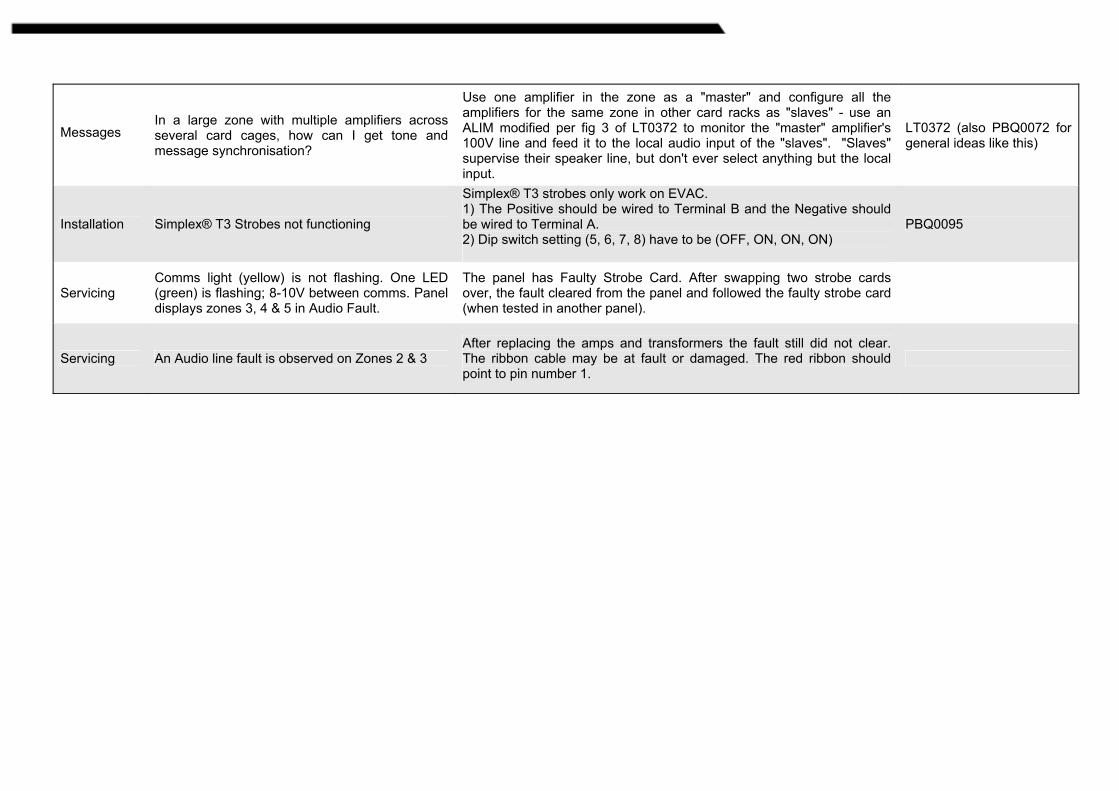
Messages In a large zone with multiple amplifiers across several card cages, how can I get tone and message synchronisation?
Use one amplifier in the zone as a "master" and configure all the amplifiers for the same zone in other card racks as "slaves" - use an ALIM modified per fig 3 of LT0372 to monitor the "master" amplifier's 100V line and feed it to the local audio input of the "slaves". "Slaves" supervise their speaker line, but don't ever select anything but the local input.
LT0372 (also PBQ0072 for general ideas like this)
Installation Simplex® T3 Strobes not functioning
Simplex® T3 strobes only work on EVAC. 1) The Positive should be wired to Terminal B and the Negative should be wired to Terminal A. 2) Dip switch setting (5, 6, 7, 8) have to be (OFF, ON, ON, ON)
PBQ0095
Servicing Comms light (yellow) is not flashing. One LED (green) is flashing; 8-10V between comms. Panel displays zones 3, 4 & 5 in Audio Fault.
The panel has Faulty Strobe Card. After swapping two strobe cards over, the fault cleared from the panel and followed the faulty strobe card (when tested in another panel).
Servicing An Audio line fault is observed on Zones 2 & 3 After replacing the amps and transformers the fault still did not clear. The ribbon cable may be at fault or damaged. The red ribbon should point to pin number 1.

- 70 - 70 of 72 SIMPLEX Fault Assistance Guide RevA
29 April 2009
TTTHHHIIISSS PPPAAAGGGEEE HHHAAASSS BBBEEEEEENNN LLLEEEFFFTTT BBBLLLAAANNNKKK IIINNNTTTEEENNNTTTIIIOOONNNAAALLLLLLYYY

- 71 - 71 of 72 SIMPLEX Fault Assistance Guide RevA
29 April 2009
6.0 National Contact Directory
- 72 - 72 of 72 SIMPLEX Fault Assistance Guide RevA
29 April 2009
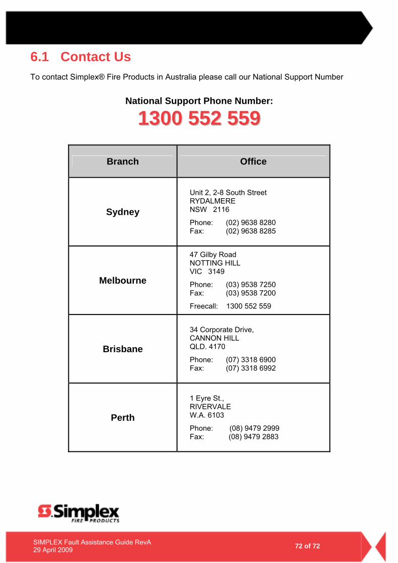
6.1 Contact Us To contact Simplex® Fire Products in Australia please call our National Support Number
National Support Phone Number:
11330000 555522 555599
Branch Office
Sydney
Unit 2, 2-8 South Street RYDALMERE NSW 2116
Phone: (02) 9638 8280 Fax: (02) 9638 8285
Melbourne
47 Gilby Road NOTTING HILL VIC 3149
Phone: (03) 9538 7250 Fax: (03) 9538 7200
Freecall: 1300 552 559
Brisbane
34 Corporate Drive, CANNON HILL QLD. 4170
Phone: (07) 3318 6900 Fax: (07) 3318 6992
Perth
1 Eyre St., RIVERVALE W.A. 6103
Phone: (08) 9479 2999 Fax: (08) 9479 2883