simplex motion technical manual€¦ · the rs485 modbus rtu interface is a half duplex...
TRANSCRIPT

Simplex Motion Technical Manual
www.simplexmotion.com Version 2018-04-12 Page 1 of 30
Simplex Motion Technical Manual
For following motor models;
SCXXXA
SMXXXA
SHXXXA

Simplex Motion Technical Manual
www.simplexmotion.com Version 2018-04-12 Page 2 of 30
About this document
Simplex Motion AB makes no representations or warranties regarding the content of this document. We reserve the
right to revise this document any time without notice and obligation.
The document describes the general usages of the following motor models: SCxxxA, SMxxxA and SHxxxA (where the
x are the motor models number). For the specific installation, specifications and dimensions of the different motor
models, see the motor specifications document for each motor series.
Index Simplex Motion Technical Manual ..................................................................................................................................... 1 1 Safety ......................................................................................................................................................................... 3
1.1 Qualification of personnel ................................................................................................................................. 3 1.2 Intended Use ...................................................................................................................................................... 3 1.3 Hazard Categories ............................................................................................................................................. 4 1.4 General safety instructions ................................................................................................................................ 4
2 Communication ......................................................................................................................................................... 5 2.1 USB communication.......................................................................................................................................... 5 2.2 Modbus communication .................................................................................................................................... 5 2.3 Register map ...................................................................................................................................................... 7
3 Device operation ...................................................................................................................................................... 13 3.1 Operating modes .............................................................................................................................................. 13 3.2 Motor data ....................................................................................................................................................... 14 3.3 PID controller .................................................................................................................................................. 14
3.3.1 Feed forward ........................................................................................................................................... 15 3.3.2 Target value ............................................................................................................................................ 15
3.4 Ramping control .............................................................................................................................................. 16 3.5 Sequence control ............................................................................................................................................. 17 3.6 Homing ............................................................................................................................................................ 18 3.7 Events .............................................................................................................................................................. 19
3.7.1 Event trigger ........................................................................................................................................... 20 3.7.2 Event execution....................................................................................................................................... 21
3.8 Recorder .......................................................................................................................................................... 22 3.9 External inputs and outputs ............................................................................................................................. 23
3.9.1 Inputs ...................................................................................................................................................... 23 3.9.2 Outputs .................................................................................................................................................... 24 3.9.3 Encoder ................................................................................................................................................... 25
3.10 Indicator LED .................................................................................................................................................. 26 4 Protection and error handling .................................................................................................................................. 27
4.1 List of error codes ............................................................................................................................................ 29 4.2 Hardware reset of registers .............................................................................................................................. 29
5 Power supply considerations and EMC ................................................................................................................... 30

Simplex Motion Technical Manual
www.simplexmotion.com Version 2018-04-12 Page 3 of 30
1 Safety
1.1 Qualification of personnel
Only technicians who are familiar with and understand the contents of this manual and the other relevant documentation
are authorized to work on and with this drive system. The technicians must be able to detect potential dangers that may
be caused by setting parameters, changing parameter values, creating and changing events and generally by the
operation of mechanical, electrical and electronic equipment. The technicians must have sufficient technical training,
knowledge and experience to recognize and avoid dangers. The technicians must be familiar with the relevant
standards, regulations and safety regulations that must be observed when working on the drive system (etc. EMC
Directive, Low Voltage directive and Machinery Directive). If the system is used outside the EU, international, national
and regional directives must be observed.
1.2 Intended Use
The integrated servomotors systems described here are products for general use that conform to the state of the art in
technology and are designed to prevent any dangers. However, drives and drive controllers that are not specifically
designed for safety functions are not approved for applications where the functioning of the drive could endanger
persons. The possibility of unexpected or unbraked movements can never be totally excluded without additional safety
equipment.
For this reason, personnel must never be in the danger zone of the servomotors unless additional suitable safety
equipment prevents any personal danger. This applies to operation of the machine during production and also to all
service and maintenance work on servomotors and the machine. The machine design must ensure personal safety.
Suitable measures for prevention of property damage are also required.
In all cases the applicable safety regulations and the specified operating conditions, such as environmental conditions
and specified technical data, must be observed.
The servomotor system must not be commissioned and operated until completion of installation in accordance with the
EMC regulations and the specifications in this manual. To prevent personal injury and damage to property damaged
servomotors systems must not be installed or operated until this is done.
Changes and modifications of the servomotor systems are not permitted and if made no warranty and liability will be
accepted.
The drive systems must not be operated in an environment subject to explosion hazard.

Simplex Motion Technical Manual
www.simplexmotion.com Version 2018-04-12 Page 4 of 30
1.3 Hazard Categories
Safety notes and general information are indicated by hazard messages in the manual. In addition there are symbols and
instructions affixed to the product that warn of possible hazards and help to operate the product safely. Depending on
the seriousness of the hazard, the messages are divided into three hazard categories.
⚠ DANGER
DANGER indicates an imminently hazardous situation, which, if not avoided, will result in death, serious injury, or equipment
damage.
⚠ WARNING
WARNING indicates a potentially hazardous situation, which, if not avoided, can result in death, serious injury, or equipment
damage
⚠ CAUTION
CAUTION indicates a potentially hazardous situation, which, if not avoided, can result in injury or equipment damage.
1.4 General safety instructions
⚠ DANGER
EXPOSED SIGNALS
Hazardous voltage levels may be present if using an open frame power supply to power the product.
Failure to follow these instructions will result in death or
serious injury.
⚠ WARNING
If connecting the motor to the machine, build an external
emergency stop circuit that immediately stops operation and shuts
down power in an emergency.
ACCESS TO MOVING PART
Always ensure that no personnel can access the motor before operation as it has accessible moving parts.
LOSS OF CONTROL
• The system manufacturer must take the potential error
possibilities of the signals and the critical functions into account to ensure a safe status during and after errors.
Some examples are: emergency stop, final position
limitation, power failure and restart.
• The assessment of error possibilities must also include
unexpected delays and the failure of signals or functions.
• Suitable redundant control paths must be in place for
dangerous functions.
• Check that measures taken are effective.
HEAT
The motor will become hot during operation, so do not touch the
motor with bare hands. Failure to observe this caution may result in burns.
MODIFICATIONS
Do not attempt to disassemble, repair, or modify the product.
Do not change any wiring while power is being supplied.
Failure to follow these instructions can result in death or
serious injury
⚠ CAUTION
FAST CHANGES IN MOVMENT
Always attach the motor to a fixed structure before use. Large
torques can be generated if target values is changed. The self-weight of the motor is then not enough to hold it stable.
HOT PLUGGING!
Do not connect or disconnect power, logic, or communication
while the device is in a powered state. Remove DC power by
powering down at the AC side of the DC power supply.
ENVIROMENT
• Install the servomotor only in environments that meet
the requirements for its protection class.
• Do not step on or place a heavy object on the motor.
Failure to observe this caution may result in injury.
• Be sure to prevent any foreign objects from entering the
product. Failure to observe this caution may result in
malfunction or fire
CABLES
Do not damage the cables or subject them to excessive stress such
as bending or stretching. Do not place heavy objects on the cables or the cables between other objects where they might be pinched.
Check the wiring to be sure it has been performed correctly. Connectors and pin layouts are sometimes different for different
models. Always confirm the pin layouts in technical documents for
your model before operation.
Failure to follow these instructions can result in equipment
damage.

Simplex Motion Technical Manual
www.simplexmotion.com Version 2018-04-12 Page 5 of 30
2 Communication The following part describes means of communication to the unit.
2.1 USB communication
(Note; SC-Serie motors do not have an USB interface)
The hardware that have a USB interface, is using the USB type B mini connector type. The interface has full speed
(12Mbit/s) and utilized the USB HID protocol (this does not require a custom driver when connecting the device to a
PC computer since the operating system provides default support for HID devices).
The device is partly powered by the USB connection; It is possible to communicate with the device and perform
configuration without additional power supply. But to start the motor the external power supply is necessary.
If several Simplex Motion devices are connected to the same PC computer, via a USB hub for example, they are
separated with unique addresses. This address is the same used for RS485 Modbus communication, and is set in register
<Address>.
Please note that the USB interface is not very robust for use in harsh environments and high levels of electrical noise.
It is very important that the USB bus and the motor power supply share the same ground potential, as the USB interface
is not isolated. The USB cable length is limited to 5 meters. For applications that require long cables and harsh
environments the Modbus interface is recommended.
The SimplexMotionTool PC software supports use of the USB interface for configuration and testing of the device.
2.2 Modbus communication
The RS485 Modbus RTU interface is a half duplex master-slave protocol. Up to 32 devices can be connected on the
same RS485 lines so that one single master can control up to 31 drive devices. Each device has a unique address
1…126. The default setting is address 1, but it is easily changed by writing to register <Address>.
Modbus ASCII mode is not supported at the moment, as it is less efficient.
Baud rate and parity settings are available through the <ModbusControl> register. The Modbus communication is
completely reset when this register is written. Default settings are 57600 baud and even parity.
All registers accessed through the Modbus protocol have 16 bits, but can be both unsigned and signed. Those registers
that have 32 bits datatypes need dual reads or writes to be accessed. The most significant 16 bits are at the even register
address, while the least significant 16 bits are at the odd address.
The following Modbus function codes are supported:
Value Description
03 Read holding registers
06 Write single register
08 Diagnostics
16 Write multiple registers
For further information on the Modbus standard please consult www.modbus.org
When using a PC computer for control, there are a number of low cost USB-RS485 converters available on the market.
To allow further flexibility the interface also supports RS232 communication as it is quite common. But the signaling
voltages are limited to 0/3.3V and do not support the RS232 standard +/-3..12V signaling. This is sometimes called
RS232 TTL. However in most cases it is possible to connect to standard RS232 ports using a series resistor of 1kOhm
between the master system TX line and the motor unit RX connection. Note that RS232 does not support several slave
devices, thus only one motor can be used at a time. When using RS232 the connections are according to:
Pin Name RS232 usage
7 IN7/RS485A RX (receive). Connect to master system TX (transmit) signal. Use a 1kOhm series
resistor if standard RS232 signal levels are used.
8 IN8/RS485B TX. (transmit). Connect to master system RX (receive) signal.

Simplex Motion Technical Manual
www.simplexmotion.com Version 2018-04-12 Page 6 of 30
The configuration is done using bits 8..11 in <ModbusControl> according to:
Value Description
0 Modbus interface disabled. Connections used for digital inputs.
1 RS485 standard (default)
2 RS485 inverted. This is the same as swapping A/B connections.
3 RS232 standard. Signal level is low when idle (0VDC).
4 RS232 inverted. Signal level is high when idle (3.3VDC).
Some additional notes:
o The RS485 bus signals are denoted A and B. Unfortunately there are systems using either A or B as the positive
signal, and in some cases it can be necessary to swap A and B. This product expects A to be the positive signal and
B to be the negative. Swapping A and B can be used by setting interface type to RS485inverted in the
<ModbusControl> register.
o Bus polarization is usually needed to define the bus state when no device is transmitting. This device has an
internal weak polarization that is sufficient for applications where a termination resistor is not used. It is also
possible to enable a strong polarization (should only be enabled on one unit on the bus) for cases when a
termination resistor is used.
o A termination resistor (100-120Ohm) is recommended when using a high baud rate (>57600) and long cables
(>50m).
o Using the Modbus protocol on some systems shows register numbering with an offset of 1.
o The RS485/RS232 interface is not isolated, so the ground potential must be the same as used for the power supply.
The SimplexMotionTool PC software supports use of the Modbus interface for configuration and testing of the device.
Simplex Motion Technical Manual
www.simplexmotion.com Version 2018-04-12 Page 7 of 30
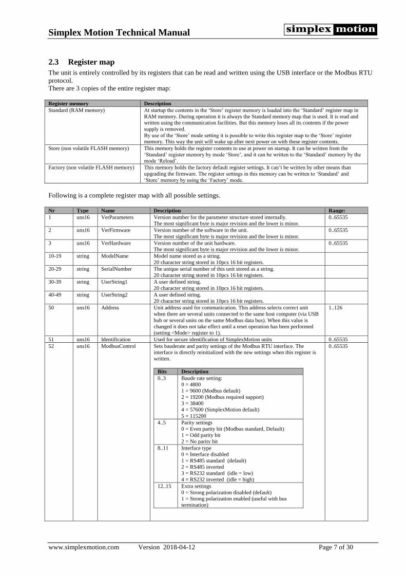
2.3 Register map
The unit is entirely controlled by its registers that can be read and written using the USB interface or the Modbus RTU
protocol.
There are 3 copies of the entire register map:
Register memory Description
Standard (RAM memory) At startup the contents in the ‘Store’ register memory is loaded into the ‘Standard’ register map in
RAM memory. During operation it is always the Standard memory map that is used. It is read and written using the communication facilities. But this memory loses all its contents if the power
supply is removed.
By use of the ‘Store’ mode setting it is possible to write this register map to the ‘Store’ register memory. This way the unit will wake up after next power on with these register contents.
Store (non volatile FLASH memory) This memory holds the register contents to use at power on startup. It can be written from the
‘Standard’ register memory by mode ‘Store’, and it can be written to the ‘Standard’ memory by the mode ‘Reload’.
Factory (non volatile FLASH memory) This memory holds the factory default register settings. It can’t be written by other means than
upgrading the firmware. The register settings in this memory can be written to ‘Standard’ and
‘Store’ memory by using the ‘Factory’ mode.
Following is a complete register map with all possible settings.
Nr Type Name Description Range:
1 uns16 VerParameters Version number for the parameter structure stored internally. The most significant byte is major revision and the lower is minor.
0..65535
2 uns16 VerFirmware Version number of the software in the unit.
The most significant byte is major revision and the lower is minor.
0..65535
3 uns16 VerHardware Version number of the unit hardware. The most significant byte is major revision and the lower is minor.
0..65535
10-19 string ModelName Model name stored as a string.
20 character string stored in 10pcs 16 bit registers.
20-29 string SerialNumber The unique serial number of this unit stored as a string. 20 character string stored in 10pcs 16 bit registers.
30-39 string UserString1 A user defined string.
20 character string stored in 10pcs 16 bit registers.
40-49 string UserString2 A user defined string. 20 character string stored in 10pcs 16 bit registers.
50 uns16 Address Unit address used for communication. This address selects correct unit
when there are several units connected to the same host computer (via USB
hub or several units on the same Modbus data bus). When this value is changed it does not take effect until a reset operation has been performed
(setting <Mode> register to 1).
1..126
51 uns16 Identification Used for secure identification of SimplexMotion units 0..65535
52 uns16 ModbusControl Sets bauderate and parity settings of the Modbus RTU interface. The interface is directly reinitialized with the new settings when this register is
written.
Bits Description
0..3 Baude rate setting:
0 = 4800 1 = 9600 (Modbus default)
2 = 19200 (Modbus required support)
3 = 38400 4 = 57600 (SimplexMotion default)
5 = 115200
4..5 Parity settings
0 = Even parity bit (Modbus standard, Default) 1 = Odd parity bit
2 = No parity bit
8..11 Interface type 0 = Interface disabled
1 = RS485 standard (default)
2 = RS485 inverted 3 = RS232 standard (idle = low)
4 = RS232 inverted (idle = high)
12..15 Extra settings
0 = Strong polarization disabled (default) 1 = Strong polarization enabled (useful with bus
termination)
0..65535

Simplex Motion Technical Manual
www.simplexmotion.com Version 2018-04-12 Page 8 of 30
100 uns16 Supply Measured supply voltage. Unit is 0.01V. 0..3000
101 uns16 TempElectronics Measured temperature of the electronics. Unit is 0.01°C 0..12500
102 uns16 TempMotor Estimated temperature of the motor winding. Unit is 0.01°C 0..12500
120 uns16 SpreadSpectrum Control of the spread spectrum feature, used to minimize conducted
switching noise on the power supply lines. This is accomplished by
continuously varying the switching frequency.
Value Description
0 Turned off
1 Frequency variation +/-1.25%
2 Frequency variation +/-2.5%
3 Frequency variation +/-5%
4 Frequency variation +/-10%, Default setting
5 Frequency variation +/-20%
0..3
121 uns16 SpeedFilter Control of motor speed measurement filter. 0 = no filtering. 4 = normal
filtering. Increasing value is equal to more filtering.
0..15
140 uns16 InputPolarity The 8 lower bits control input polarity on the inputs IN1-IN7. When set to 0
the corresponding input is active high, while it is active low if set to 1.
0..255
141 uns16 InputThreshold Threshold level for low/high for the inputs IN5-8. The 16bit value
represents the range 0V to max V. Depending on what model is used, the
max V differs, se motor specification for exact value. A typical setting at 1.0V is the value 13107 for a +5V system.
0..65535
145 uns16 Input 8 bits hold states for digital inputs IN1..7, IN1 in least significant bit. 1 =
active input.
0..255
150-153 uns16 OutputControl[4] This register controls the mode of a digital output, allowing simple, pulse, PWM or RC servo pulse output. See section 3.9.2.
0..65535
160-163 uns16 Output[4] The 4 output values. These are interpreted differently depending on the
output modes set in the respective OutputControl register.
0..65535
170-173 uns16 Analog[4] Values from analog inputs AIN1..4. The values are full 16 bits that represent 0 to Max voltage on inputs. Depending on what model is used, the
max V differs, se motor specification for exact value.
Nr Description
170 AIN1
171 AIN2
172 AIN3
173 AIN4
0..65535
180 uns16 EncoderControl Controls function of quadrature encoder inputs.
Bits Description
0..3 Encoder mode 0 = disabled
1 = quadrature encoder input
2 = step/direction input interface 8 = quadrature encoder output (Applicable on SM-
Series and SH-Series. Not applicable to SC-Series)
4..7 Encoder filter
Sets encoder signal filtering 0..7. Default is 4.
8 Invert direction if set to 1
9 Enable pull up resistor if set to 1. There is a weak pull
down resistor when set to 0 (default).
Encoder filter values:
Value Max pulse frequency
0 10 MHz
1 5 MHz
2 2.5 MHz
3 1.25 MHz
4 625 kHz
5 312 kHz
6 156 kHz
7 78 kHz
0..65535
184/185 int32 Encoder Value from quadrature encoder interface. Counts 4 * pulse frequency from encoder when using the quadrature encoder mode. In the step/direction
mode this register holds the pulse count.
-2147483648 .. 2147483647
200/201 int32 MotorPosition Current motor position. 4096 positions per revolution. -2147483648 ..
2147483647

Simplex Motion Technical Manual
www.simplexmotion.com Version 2018-04-12 Page 9 of 30
202 int16 MotorSpeed Measured motor speed. Unit is positions/second / 16.
Value in unit RPM = 60 * MotorSpeed / 256.
0..25600
203 int16 MotorTorque Measured motor torque. Unit is 1mNm. Depends on
motor model
204 int16 MotorTorqueMax Setting of torque limit value. Unit is 1mNm. Depends on motor model
205 int16 MotorTorqueStop Maximum torque to use for quickstop of motor in case of error. Depends on
motor model
206 int16 MotorVd Motor flux voltage. Only for debugging purposes -32768..32767
207 int16 MotorVq Motor torque generating voltage. Only for debugging purposes. -32768..32767
208 uns16 MotorAngle Motor commutation angle within electrical turn. Only for debugging
purposes.
0..65535
222 int16 CurrId Motor flux current for debugging. -32768..32767 223 int16 CurrIq Motor torque current for debugging. -32768..32767 300 int16 RegKp Regulator proportional parameter. Normal values 500..2000. 0..10000
301 int16 RegKi Regulator integrative parameter. Normal values 500..2000. 0..10000
302 int16 RegKd Regulator derivative parameter. Normal values 500..2000. 0..10000
303 int16 RegLimit Limit value for regulator integration. Normal values 100..500. 0..65535
304 int16 RegDelay Controls derivative calculation filtering by setting time delay. Normal
values 2..4
Larger values limit the noise, but introduces some time lag.
0..8
305 int16 RegFriction Speed feedforward term. Used when friction increases with speed.
Unit is Nm/rpm * 10E-6
0..200
306 int16 RegInertia Acceleration feedforward term. Used for high inertia loads. Unit is load inertia, kgm2 * 10E-6
0..1000
307 uns16 RegDeadband Deadband on regulator input error. Typical values 0..20. Higher values
reduce motor noise when stationary (regulator hunting) but degrades positioning precision.
0..100
308 int16 RegError Regulator error, sometimes called following error. The actual difference
between present and target values that are inputs to the regulator. The resolution is 16 times larger than the actual position difference, so the
maximum value 32767 corresponds to 2048 positions, or one half shaft
revolution.
-32768 ..
32767
309 uns16 RegErrorMax Maximum allowed regulator error. Sets status bit when the error gets beyond this value. Same unit as the RegError register.
0..65535
310 int16 RegOutput Regulator output (Torque request). Value is relative to the model maximum
torque. Useful for debugging purposes.
0..65535
350 int16 RampSpeed Current speed command. Unit is positions/second / 16. 0..25600
351 int16 RampSpeedMax Setting of maximum speed. Unit is positions/second / 16. 0..25600
352 int16 RampAcc Current acceleration command. Unit is positions/second^2 / 256.
Multiply this value by 3.75 to get the unit RPM/s.
0..20000
353 int16 RampAccMax Setting of acceleration value. Unit is positions/second^2 / 256. 0..20000
354 int16 RampDecMax Setting of deceleration value. Unit is positions/second^2 / 256. 0..20000
355 Int16 RampJerk Not used at the moment. Will later be implemented to control 3rd derivative
of position during ramp control.
400 uns16 Mode Controls mode of drive, according to:
Value Name Description
0 Off Stop mode, motor is off
1 Reset Resets all running data and then enters
Off mode.
4 Shutdown When the driver has been shutdown
because of an error. Motor is off.
5 Quickstop Motor stopped in a controlled manner,
then turned off.
6 Firmware Firmware upgrade mode. Causes
control to be passed to a bootloader to
receive new firmware through the USB
connection.
7 Factory Resets all parameters to factory default
settings.
8 Reload Reloads parameters from non volatile memory and then enters Reset mode.
9 Store Store current registers to non volatile
memory. Then jumps to Off mode.
10 Pwm PWM mode, open loop control.
20 Position Closed loop control of position.
21 PositionRamp Closed control of position with ramp
control.
32 Speed Speed control mode. Position is
generated from a set speed and position regulation is done. This ensures a more
precise speed control and a wider speed
0..201
Simplex Motion Technical Manual
www.simplexmotion.com Version 2018-04-12 Page 10 of 30
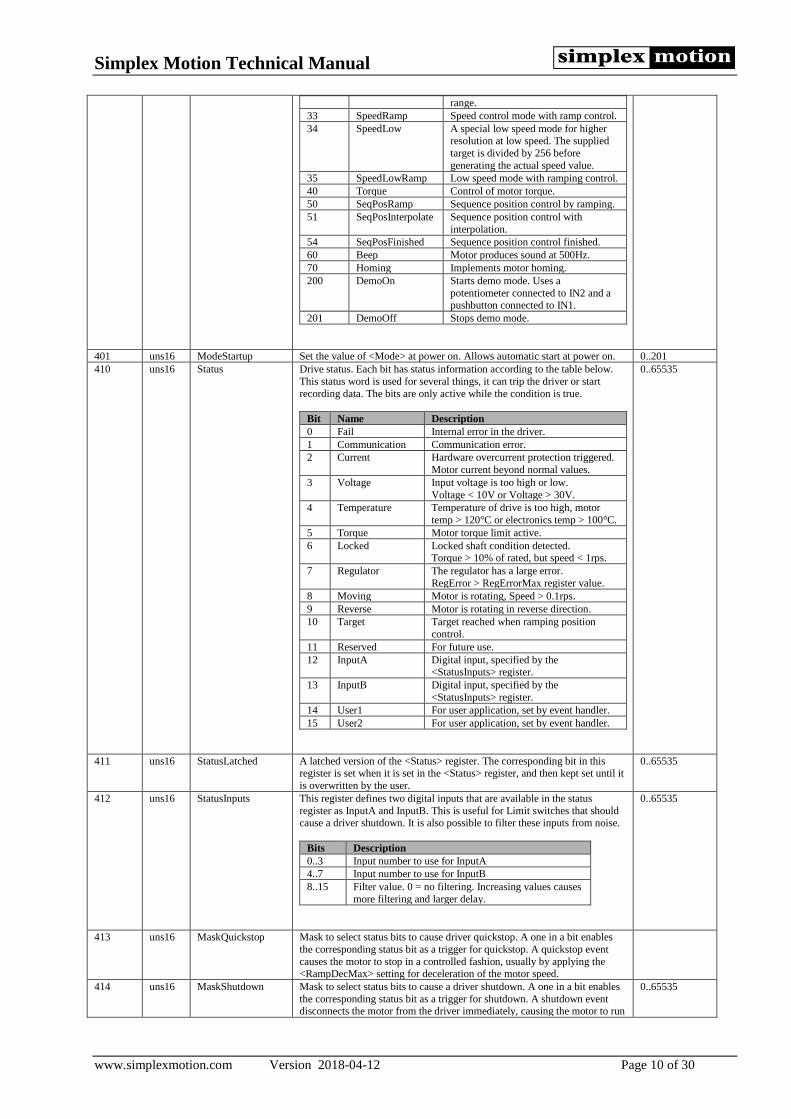
range.
33 SpeedRamp Speed control mode with ramp control.
34 SpeedLow A special low speed mode for higher resolution at low speed. The supplied
target is divided by 256 before
generating the actual speed value.
35 SpeedLowRamp Low speed mode with ramping control.
40 Torque Control of motor torque.
50 SeqPosRamp Sequence position control by ramping.
51 SeqPosInterpolate Sequence position control with
interpolation.
54 SeqPosFinished Sequence position control finished.
60 Beep Motor produces sound at 500Hz.
70 Homing Implements motor homing.
200 DemoOn Starts demo mode. Uses a
potentiometer connected to IN2 and a pushbutton connected to IN1.
201 DemoOff Stops demo mode.
401 uns16 ModeStartup Set the value of <Mode> at power on. Allows automatic start at power on. 0..201
410 uns16 Status Drive status. Each bit has status information according to the table below.
This status word is used for several things, it can trip the driver or start
recording data. The bits are only active while the condition is true.
Bit Name Description
0 Fail Internal error in the driver.
1 Communication Communication error.
2 Current Hardware overcurrent protection triggered.
Motor current beyond normal values.
3 Voltage Input voltage is too high or low.
Voltage < 10V or Voltage > 30V.
4 Temperature Temperature of drive is too high, motor
temp > 120°C or electronics temp > 100°C.
5 Torque Motor torque limit active.
6 Locked Locked shaft condition detected. Torque > 10% of rated, but speed < 1rps.
7 Regulator The regulator has a large error.
RegError > RegErrorMax register value.
8 Moving Motor is rotating, Speed > 0.1rps.
9 Reverse Motor is rotating in reverse direction.
10 Target Target reached when ramping position
control.
11 Reserved For future use.
12 InputA Digital input, specified by the <StatusInputs> register.
13 InputB Digital input, specified by the
<StatusInputs> register.
14 User1 For user application, set by event handler.
15 User2 For user application, set by event handler.
0..65535
411 uns16 StatusLatched A latched version of the <Status> register. The corresponding bit in this register is set when it is set in the <Status> register, and then kept set until it
is overwritten by the user.
0..65535
412 uns16 StatusInputs This register defines two digital inputs that are available in the status
register as InputA and InputB. This is useful for Limit switches that should cause a driver shutdown. It is also possible to filter these inputs from noise.
Bits Description
0..3 Input number to use for InputA
4..7 Input number to use for InputB
8..15 Filter value. 0 = no filtering. Increasing values causes
more filtering and larger delay.
0..65535
413 uns16 MaskQuickstop Mask to select status bits to cause driver quickstop. A one in a bit enables
the corresponding status bit as a trigger for quickstop. A quickstop event
causes the motor to stop in a controlled fashion, usually by applying the <RampDecMax> setting for deceleration of the motor speed.
414 uns16 MaskShutdown Mask to select status bits to cause a driver shutdown. A one in a bit enables
the corresponding status bit as a trigger for shutdown. A shutdown event disconnects the motor from the driver immediately, causing the motor to run
0..65535

Simplex Motion Technical Manual
www.simplexmotion.com Version 2018-04-12 Page 11 of 30
freely from its inertia to a stop.
415 uns16 Error This register holds the latest generated error code. See 4.1 for error codes. 0..65535
420/421 uns32 Time Tracks time as 2000 counts per second. Wraps around after about 12 days.
This register can also be written.
0 .. 4294967295
450/451 int32 TargetInput Target value for regulator. Written here when <TargetSelect> = Register. -2147483648 ..
2147483647
452 uns16 TargetSelect Sets the target source according to:
Value Name Description
0 Register Target is set by a register content. Written to register <TargetInput>.
1 Analog 1 Analog value from AIN1 is used as target.
Value 0..65535
2 Analog 2 Analog value from AIN2 is used as target.
3 Analog 3 Analog value from AIN3 is used as target.
4 Analog 4 Analog value from AIN4 is used as target.
5 Encoder Encoder interface is used for target values. The
encoder can be set for quadrature encoder
input or Step/Dir interface for step motor emulation. The target value is taken from the
<Encoder> register.
6 Pulse A digital input pulse length is used to set target values. Compatible with RC servo pulses.
Not yet implemented.
0..6
453 int16 TargetMul Value to multiply with input target value before used by the regulator. -32768 .. 32767
454 int16 TargetDiv Value to divide the input target with before it is used by the regulator. -32768 .. 32767
455 int16 TargetOffset Value to add to the input target before it is used by the regulator. The Offset
is applied after <TargetMul> and <TargetDiv>.
-32768 .. 32767
456/457 int32 TargetMin Minimum value for target value -2147483648 ..
2147483647
458/459 int32 TargetMax Maximum value for target value -2147483648 ..
2147483647
460 int16 TargetHysteresis Hysteresis value to remove noise from target values. This is typically useful
when the target source is an analog input. Applied after Mul/Div/Offset.
Typical values 0..1000.
0..65535
461 uns16 TargetFilter Allows filtering of target values to reduce noise and limit rate of change. 0 = no filtering, increasing values allows more filtering. Typical values 0..7.
0..16
462/463 int32 TargetPresent The current target value as it is sent to the regulator. Useful for debugging. -2147483648 ..
2147483647
480-483 uns16 HomeSequence[4] Sequence definition for homing sequence. 4 individual sequence steps. The homing features are used to find a position reference at system startup.
See more in section 3.6.
0..65535
490 int16 HomeOffset Position value to set at homing point -32768..32767
491 uns16 HomeSpeed Reference speed to use for homing. Unit is positions/second / 16. 0..25600
492 uns16 HomeAcc Homing acceleration. Unit is positions/second^2 / 256. 0..20000
493 uns16 HomeTorque Torque limit to use by hard stop homing. Unit is mNm. 0..2000
494 uns16 HomeDoneMode Mode to switch to when homing sequence is finished. This value is then
written to register 400.
0..201
495 int16 HomeChange The amount of position change after a completed homing. Useful for debugging and basically shows how much repetitive homings deviate.
-32768..32767
500 uns16 SeqControl Not currently in use. Use register 400 <Mode> to use Seq function. See
section 3.5.
501 uns16 SeqIndex Current index into the table of positions and time values. Can have values
from 0 to 15. During sequence control this register automatically increments
for each processed table entry. See section 3.5.
0..15
510-540 int32 SeqTarget[16] Target values of the table. Unit is 1/4096 revolution. See section 3.5. -2147483648 ..
2147483647
570-585 uns16 SeqTime[16] Time values of the table. Unit is milliseconds. 0..3999
600 uns16 ApplControl Control for custom application code loaded into firmware in the device. 0..65535
601 uns16 ApplStatus Status information from custom application code loaded into the firmware. 0..65535
602 uns16 ApplRuntime Runtime indication for custom application code. Indicates the percent of available runtime that is used up by the application code.
0..100
603 uns16 ApplVersion Version of the custom application code.
The most significant byte is major revision and the lower is minor.
0..65535
620-627 uns16 ApplData 8 registers of general use for the custom application. 0..65535
640-647 uns16 Debug 8 registers used for debugging of the custom application. 0..65535
680-699 uns16 EventControl[8] Control register for event.
Events are used to cause simple actions to happen from trigger conditions.
For example to set a certain register value when a digital input is activated from a pushbutton, or activate an output when a register value is above a
certain threshold.
0..65535

Simplex Motion Technical Manual
www.simplexmotion.com Version 2018-04-12 Page 12 of 30
Bits Description
0..3 Trigger operation
Used to determine if trigger condition is met.
4..7 Trigger filter
Allows filtering of trigger condition.
8..11 Trigger type
0 = Active, 1 = Edge, 2 = Repeat.
12..15 Data operation
Used to manipulate register when event is executed.
See section 3.7 for more information.
700-719 uns16 EventTrgReg[8] Trigger register number. 0..65535
720-739 uns16 EventTrgData[8] Trigger data value. 16-bit value to use with trigger register and operator. 0..65535
740-759 uns16 EventSrcReg[8] Source register number. 0..65535
760-779 uns16 EventSrcData[8] Source data value. 16-bit value to use with source register and operator. 0..65535
780-799 uns16 EventDstReg[8] Destination register to write event result to. 0..65535
900 uns16 RecState State of the recorder. The recorder is used to store measurements in a rapid
pace for debugging and inspection of dynamic behavior. There is space for
500 measurements of 4 channels, each being 16 bits wide.
Value Name Description
0 Idle Recorder in idle, not used.
1 Continuous Recording continuously
2 Single Perform one complete recording of 500 values.
3 Trigger Trigger enabled, recording started when
trigger condition met.
0..3
901 uns16 RecTrigger Trigger word. This word is used as a mask with the status register. When an
active status bit corresponding to an active <RecTrigger> bit appears the trigger condition is met.
0..65535
902 uns16 RecPeriod Sets the recording speed as number of regulator cycles between recordings.
Setting this value to 0 provides the fastest possible recording speed, taking
all 500 measurements in exactly 0.25s.
0..65535
903 uns16 RecPreceding Sets the number of samples to appear before trigger. This feature makes it
possible to measure just prior to trigger condition.
0..1000
904 uns16 RecOffset Offset position into data for start. Since the data area is used as a circular
buffer that runs continuously, the first data point is not always in the first memory position. Instead the first data is at the <RecOffset> position.
0..999
905-908 uns16 RecRegister[4] Register numbers for the 4 channels to record. 0..4999
1000-
1499
int16 RecData1[500] Data for recording channel 1. Data can be uns16 or int16 depending on the
source register. 500 values in consecutive register addresses.
0..65535
2000-
2499
int16 RecData2[500] Data for recording channel 1. Data can be uns16 or int16 depending on the
source register. 500 values in consecutive register addresses.
0..65535
3000-
3499
int16 RecData3[500] Data for recording channel 1. Data can be uns16 or int16 depending on the
source register. 500 values in consecutive register addresses.
0..65535
4000-
4499
int16 RecData4[500] Data for recording channel 1. Data can be uns16 or int16 depending on the
source register. 500 values in consecutive register addresses.
0..65535

Simplex Motion Technical Manual
www.simplexmotion.com Version 2018-04-12 Page 13 of 30
3 Device operation This chapter will explain the operation of the unit and how it is controlled through the registers.
3.1 Operating modes
The <Mode> register controls the overall behavior of the motor unit. The following table describes the different modes:
Name: Value: Description:
Off 0 Stop mode, motor is off.
Reset 1 Resets drive
All running data is reset, such as current position. Automatically changes <Mode> to Off mode.
Shutdown 4 The driver is shut down because of an error. Motor is off. This happens if any status bits enabled by the <MaskShutdown> becomes active. This is a feature to
shutdown the motor in case of events such as high temperature, internal error etc.
Quickstop 5 Motor stopped in a controlled manner, then turned off. A quickstop event causes the motor to stop in a controlled fashion, usually by applying the <RampDecMax> setting for deceleration of the motor speed. This
happens if a status bit enabled by the corresponding bit in the <MaskQuickstop> becomes active.
Firmware 6 Firmware upgrade mode. Causes control to be passed to a bootloader to receive new firmware through the
USB connection. A special PC software is needed to download the new firmware.
Factory 7 Resets all parameters to factory default settings. Then sets <Mode> to Reset mode.
Reload 8 Reloads parameters from non volatile memory and resets all running data. This is equivalent to cycling the
powersupply to restart the unit. The default register contents that are loaded decide which is the final mode
setting.
Store 9 Store the current registers to non volatile memory
After the registers has been stored the mode changes automatically to the previous mode.
Pwm 10 PWM mode, open loop control The <Target> value [-32768..32767] is directly converted to motor voltage, where -32768 is full speed
reverse, 0 is standstill, and 32767 is full speed forwards. There is no regulator involved, and no ramping.
Torque is not limited. This mode is mainly supported for testing and has limited use.
Position 20 Closed loop control of position This mode uses the PID regulator to perform closed loop regulation of the motor position. Torque limit is
active.
PositionRamp 21 Closed loop control of position with ramp control Similar to the ‘Position’ mode but does also support ramping control of the position. This means controlled
acceleration and speed according to user settings. This is the preferred mode since it typically limits torque
and supply currents and causes even motions with less vibration.
Speed 32 Speed control mode. Motor position is generated from a set speed and position regulation is done. This results in a more precise speed control and the ability to control speed down to 0 rpm.
SpeedRamp 33 Speed control mode with ramp control. This is the recommended mode for general speed control
applications.
SpeedLow 34 A special low speed mode for higher resolution at low speed. The supplied target is divided by 256 before generating the actual speed value.
SpeedLowRamp 35 Low speed mode with ramping control.
Torque 40 Control of motor torque. Has a speed limit feature as well (set maximum speed in the <RampSpeedMax>
register). The required torque (target value) is scaled so that a signed 16 bit value covers the motor maximum torque range. So the maximum torque value is +/-32767.
Beep 60 Motor produces sound at 500Hz
Target value sets amplitude. Can be used for user communication.
Homing 70 Implements motor homing. Setting this mode starts the homing sequence. Once finished the mode register is set to the contents in the <HomeDoneMode> register.
DemoOn 200 Starts demo mode. Uses a 10k potentiometer connected to +5V/IN2/GND and a pushbutton connected from
IN1 to GND for user control. The demo mode uses the potentiometer to set target value, and a pushbutton to change between 4 testmodes.
Each press advances the testmode one step, while pressing for more than 1 second jumps to the first
testmode.
Nr Testmode Potentiometer range
1 Speed regulation Speed from 0 to 5000rpm.
2 Low speed regulation Speed from 0 to 20rpm.
3 Position regulation Position from 0 to 8192 (2 turns)
4 Position regulation with ramping Position from 0 to 65535 (16 turns)
DemoOff 201 Stops demo mode Changes <Mode> to ‘Reset’ mode after turning the demo mode off.
Simplex Motion Technical Manual
www.simplexmotion.com Version 2018-04-12 Page 14 of 30
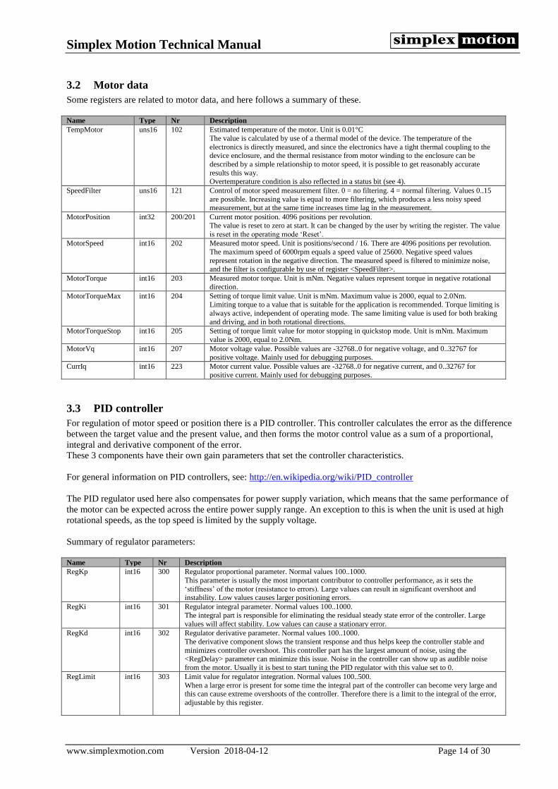
3.2 Motor data
Some registers are related to motor data, and here follows a summary of these.
Name Type Nr Description
TempMotor uns16 102 Estimated temperature of the motor. Unit is 0.01°C
The value is calculated by use of a thermal model of the device. The temperature of the
electronics is directly measured, and since the electronics have a tight thermal coupling to the device enclosure, and the thermal resistance from motor winding to the enclosure can be
described by a simple relationship to motor speed, it is possible to get reasonably accurate
results this way. Overtemperature condition is also reflected in a status bit (see 4).
SpeedFilter uns16 121 Control of motor speed measurement filter. 0 = no filtering. 4 = normal filtering. Values 0..15
are possible. Increasing value is equal to more filtering, which produces a less noisy speed measurement, but at the same time increases time lag in the measurement.
MotorPosition int32 200/201 Current motor position. 4096 positions per revolution.
The value is reset to zero at start. It can be changed by the user by writing the register. The value
is reset in the operating mode ‘Reset’.
MotorSpeed int16 202 Measured motor speed. Unit is positions/second / 16. There are 4096 positions per revolution.
The maximum speed of 6000rpm equals a speed value of 25600. Negative speed values
represent rotation in the negative direction. The measured speed is filtered to minimize noise, and the filter is configurable by use of register <SpeedFilter>.
MotorTorque int16 203 Measured motor torque. Unit is mNm. Negative values represent torque in negative rotational
direction.
MotorTorqueMax int16 204 Setting of torque limit value. Unit is mNm. Maximum value is 2000, equal to 2.0Nm. Limiting torque to a value that is suitable for the application is recommended. Torque limiting is
always active, independent of operating mode. The same limiting value is used for both braking
and driving, and in both rotational directions.
MotorTorqueStop int16 205 Setting of torque limit value for motor stopping in quickstop mode. Unit is mNm. Maximum
value is 2000, equal to 2.0Nm.
MotorVq int16 207 Motor voltage value. Possible values are -32768..0 for negative voltage, and 0..32767 for
positive voltage. Mainly used for debugging purposes.
CurrIq int16 223 Motor current value. Possible values are -32768..0 for negative current, and 0..32767 for
positive current. Mainly used for debugging purposes.
3.3 PID controller
For regulation of motor speed or position there is a PID controller. This controller calculates the error as the difference
between the target value and the present value, and then forms the motor control value as a sum of a proportional,
integral and derivative component of the error.
These 3 components have their own gain parameters that set the controller characteristics.
For general information on PID controllers, see: http://en.wikipedia.org/wiki/PID_controller
The PID regulator used here also compensates for power supply variation, which means that the same performance of
the motor can be expected across the entire power supply range. An exception to this is when the unit is used at high
rotational speeds, as the top speed is limited by the supply voltage.
Summary of regulator parameters:
Name Type Nr Description
RegKp int16 300 Regulator proportional parameter. Normal values 100..1000.
This parameter is usually the most important contributor to controller performance, as it sets the
‘stiffness’ of the motor (resistance to errors). Large values can result in significant overshoot and instability. Low values causes larger positioning errors.
RegKi int16 301 Regulator integral parameter. Normal values 100..1000.
The integral part is responsible for eliminating the residual steady state error of the controller. Large
values will affect stability. Low values can cause a stationary error.
RegKd int16 302 Regulator derivative parameter. Normal values 100..1000.
The derivative component slows the transient response and thus helps keep the controller stable and
minimizes controller overshoot. This controller part has the largest amount of noise, using the <RegDelay> parameter can minimize this issue. Noise in the controller can show up as audible noise
from the motor. Usually it is best to start tuning the PID regulator with this value set to 0.
RegLimit int16 303 Limit value for regulator integration. Normal values 100..500.
When a large error is present for some time the integral part of the controller can become very large and this can cause extreme overshoots of the controller. Therefore there is a limit to the integral of the error,
adjustable by this register.

Simplex Motion Technical Manual
www.simplexmotion.com Version 2018-04-12 Page 15 of 30
RegDelay int16 304 Controls derivative calculation filtering, which also produces a delay. Normal values 2..4, range 0..8.
Large values will decrease the noise in the derivative component of the regulator, but at the same time
increase time lag.
RegFriction int16 305 Speed feedforward term. Used when friction increases with speed.
Setting this parameter correctly greatly reliefs the PID controller and thus decreases the controller error. Unit is Nm/rpm * 10E-6
RegInertia int16 306 Acceleration feedforward term. Used for high inertia loads.
Setting this parameter correctly greatly reliefs the PID controller and thus decreases the controller error. Unit is load inertia, kgm2 * 10E-6
RegDeadband uns16 307 Dead band on regulator input error. When the motor is stationary in position regulation mode it is
common to hear some audible motor noise. This comes from the constant regulation to stay at the target
position, sometimes called ‘regulator hunting’. If positioning precision can be allowed to degrade somewhat it is possible to get rid of this noise. By setting a dead band the regulator will not care about
errors less than this dead band value, and thus the regulator will be idle.
Typical values 0..20. 0 = turn off dead band feature.
RegError int16 308 Regulator error, sometimes called following error.
This value is the calculated controller error. Observing this value lets the user measure the performance
of the motor drive unit. It is a good indicator of controller performance when tuning the regulator parameters.
The resolution is 16 times larger than the actual position difference, so the maximum value 32767
corresponds to 2048 positions, or one half shaft revolution.
RegErrorMax uns16 309 Maximum allowed regulator error. Sets status bit ‘Regulator’ when the error gets beyond this value. This can be used to monitor if the regulator error has been beyond a certain value during a session. Or to shut
down the unit if error gets really large. Same unit as register <RegError>.
RegOutput int16 310 Regulator output (Torque request). Value is signed 16bits relative to the model maximum torque. Useful for debugging purposes.
3.3.1 Feed forward
In some cases the motor speed and/or acceleration is known, and this makes it possible to help the PID controller by
introducing feed forward components. One such case is when running ramp controlled moves, where the target
acceleration and speed is continuously calculated. If characteristics of the motor load is known, it is possible to make
use of this information for improved control. There are two feed forward components, one for speed and one for
acceleration.
The speed feed forward term is used to compensate for loads where the torque increases with rotational speed. The
register used is <RegFriction>, and the unit is Nm/rpm * 10E-6. This value is difficult to calculate, so usually
experimenting will be necessary. A good start value can be 100.
The acceleration feed forward term compensates for the load inertia, as the torque needs to be increased to change the
rotational speed. This is especially important in high inertia applications, such as linear positioning devices with heavy
loads. This value can usually be calculated, but experimenting can also be used to find an appropriate value. The
register used is <RegInertia> and the unit is load inertia (as seen on the motor shaft) kgm2 * 10E-6.
To test and trim the feed forward components one can briefly disable the regulator by setting the PID controller
parameters (RegKp, RegKi, RegKd) to zero, and apply a ramp controlled position move. By observing the regulator
error across the movement (by using the recorder, see 3.8) one can change the parameters until the error is minimized.
There is a feature in the SimplexMotionTool PC software to aid in this tuning.
3.3.2 Target value
The target value is the PID controller setpoint value. It can be obtained from several different sources, configured by the
register <TargetSelect>:
Name Value Description
Register 0 Target is set by a register content. Written to register <TargetInput>.
This setting is typically used when the device is continuously controlled through the communication bus.
AIN1 1 Analog value from IN1 is used as target. The analog value has the range 0..65535. This makes setting of the target value by a potentiometer possible. Connect the potentiometer as a resistive divider
between the supplied +5V and GND. Any other voltage source providing a 0..+5V voltage can be used.
AIN2 2 Analog value from IN2 is used as target.
AIN3 3 Analog value from IN3 is used as target.
AIN4 4 Analog value from IN4 is used as target.
Encoder 5 The encoder input is used as target.
The encoder output is available in register <Encoder>, and this value is used as target value. The encoder interface can
be configured both for quadrature encoder input and for step/direction signal interface. This feature makes it easy to track another motor that supplies an encoder output, or to emulate a step motor interface.
Pulse 6 A digital input pulse length is used to set target values. Compatible with 1-2ms RC servo pulses.
Not implemented yet.

Simplex Motion Technical Manual
www.simplexmotion.com Version 2018-04-12 Page 16 of 30
A few more settings are available for the handling of target values. Scaling and offsetting of target values is of great use
when the target source is some external input such as an analog input. The registers <TargetMul> and <TargetDiv> is
used for scaling, and the <TargetOffset> for offsetting. The offset is applied after the multiplication and division
operations.
It is possible to limit target values by min and max bounds. This is done by the <TargetMin>/<TargetMax> registers.
There are also features to deal with noise on the input target values. This can be done in two ways, by hysteresis or by
filtering. The <TargetHysteresis> register allows the target value to change by small amounts, less than the register
value, before the actual used target changes. Setting the register to zero eliminates this feature. The <TargetFilter>
register allows filtering instead. A value of zero disables the filter, while an increasing value adds more filtering.
For debugging, the final target value as sent to the PID regulator, can be read from the register <TargetPresent>.
A full summary of target related registers:
Name Type Nr Description
TargetInput int32 450/451 Target value for regulator. Written here when TargetSelect = Register.
TargetSelect uns16 452 Sets the target source according to:
Value Name Description
0 Register Target is set by a register content. Written to
register TargetInput.
1 Analog 1 Analog value from AIN1 is used as target.
2 Analog 2 Analog value from AIN2 is used as target. 3 Analog 3 Analog value from AIN3 is used as target. 4 Analog 4 Analog value from AIN4 is used as target. 5 Encoder Encoder interface is used, enabling both
quadrature encoder input or step/direction signals.
6 Pulse A digital input pulse length is used to set target
values. Compatible with RC servo pulses.
TargetMul uns16 453 Value to multiply with input target value before used by the regulator.
TargetDiv uns16 454 Value to divide the input target with before it is used by the regulator.
TargetOffset uns16 455 Value to add to the input target before it is used by the regulator.
TargetMin int32 456/457 Minimum value for target value
TargetMax int32 458/459 Maximum value for target value
TargetHysteresis int16 460 Hysteresis value to remove noise from target values. This is typically useful when the target
source is an analog input. Applied after Mul/Div/Offset. Typical values 0..1000.
TargetFilter uns16 461 Allows filtering of target values to reduce noise and limit rate of change.
0 = no filtering, increasing values allows more filtering. Typical values 0..7.
TargetPresent int32 462/463 The current target value as it is sent to the regulator.
3.4 Ramping control
In most applications it is desirable to limit acceleration and speed values to configurable levels. This is accomplished by
ramping control. It is available both for speed control and for position control. The mode setting (see 3.1) determines if
it is being used or not.
Acceleration limits are divided in two registers, one for acceleration and one for deceleration. This is done since
applications with large inertia loads may need to keep low deceleration rates to limit the overvoltage created when the
energy from the mechanical load is transferred to the power supply (the motor acts as a generator).
The following table summarizes the available registers for ramping control:
Name Type Nr Description
RampSpeed int16 350 Current speed command. Unit is positions/second / 16. Values 0..25600. This value changes continuously during acceleration/deceleration to reflect the current target speed. It is
also used to implement the speed feed forward component of the PID regulator.
RampSpeedMax int16 351 Setting of maximum speed. Unit is positions/second / 16. This is the speed limit for speed control mode, and the top speed used for position moves in position
control mode.
RampAcc int16 352 Current acceleration command. Unit is positions/second^2 / 256.
This value reflects the present acceleration. Used by the acceleration feed forward component of the PID regulator.
RampAccMax int16 353 Setting of acceleration value. Unit is positions/second^2 / 256.
RampDecMax int16 354 Setting of deceleration value. Unit is positions/second^2 / 256.

Simplex Motion Technical Manual
www.simplexmotion.com Version 2018-04-12 Page 17 of 30
3.5 Sequence control
To simplify sequence of movements there is a sequence feature. This feature is based on a table of 16 entries with
position and time values. The table resides on registers <SeqTarget0> - <SeqTarget15> and <SeqTime0> -
<SeqTime15>. Position values in <SeqTargetX> registers are standard motor position values (4096 per revolution), and
time values in <SeqTimeX> are in milliseconds. The index of the current table entry is stored in register <SeqIndex>.
When a table entry has been processed (the specified time has passed), the <SeqIndex> register is incremented, and the
next table entry processed. If at the last table entry the index pointer will simply wrap-around to 0 to start over in the
table. If a time value of 0 is encountered, the sequence will be immediately stopped and the <Mode> register will be
changed to reflect this.
This feature can operate in two modes:
Mode Description
Ramping control sequence A ramping movement is done to the specified position and the specified time is used for delay until next movement. The motor typically stands still for a moment before the next move, and the specified time should therefore be
longer than the time needed to perform the ramp move.
For each table entry: A ramp move is started to the specified position, and the delay timer restarted to the specified
time value. When the time has elapsed the next table entry is processed. The sequence is terminated by a time value
of 0 in a table entry, or if the <Mode> register is changed.
Interpolation control
The motor performs interpolation of the target value between tables entries. This mode is for continuous motion
without stops.
For each table entry: A movement is started from the current table entry position towards the next table entry
position, to finish after the time specified in the current table entry. Each such movement will have constant speed. In future implementation there will be possibilities to also interpolate speed to have constant acceleration.
This mode can be used with a master system continuously writing new values to the table as they are consumed, and in such a way implement continuous custom motion with the limited bandwidth of the communication to the motor.
By reading the <SeqIndex> the master can tell what table entries has already been consumed and then write new
values to those positions. The table pointer will wrap around from last to first table entry as long as no 0 value in the time entry has been encountered.
The following <Mode> values are used to control this feature:
<Mode> register value Description
50 Sequence control of position by ramp control
51 Sequence control of position by interpolation
54 Sequence control of position is finished. When a time value of 0 is
encountered the sequence control is terminated and <Mode> changed to
this value.
The following table summarizes the available registers for sequence control:
Name Type Nr Description
SeqIndex uns16 501 Current index into the table of positions and time values. Can have values from 0 to 15. During
sequence control this register automatically increments for each processed table entry.
SeqTarget[15] int32 510-
541
Target values of the table. Unit is 1/4096 revolution.
SeqTime[15] uns16 570-
585
Time values of the table. Unit is milliseconds.

Simplex Motion Technical Manual
www.simplexmotion.com Version 2018-04-12 Page 18 of 30
3.6 Homing
In many applications the position control is in absolute terms. This requires the system to obtain a position reference at
startup. This procedure is commonly termed ‘homing’ or ‘referencing’ and often operates by slowly moving the motor
in one direction until a home switch is engaged. When the switch is operated the motor position is reset to some known
value. There are a lot of different schemes for the homing sequence though, and therefore a flexible 4-step homing
sequence is supported by the SimplexMotion motor units.
The general homing speed and acceleration is set by the HomeSpeed and HomeAcc registers.
Each of the sequence steps are configured by a 16-bit HomeSequence register.
Bit 15 Bit 14 Bit 13 Bit 12 Bit 11 Bit 10 Bit 9 Bit 8 Bit 7 Bit 6 Bit 5 Bit 4 Bit 3 Bit 2 Bit 1 Bit 0
Relative speed Filter Polarity Direction Condition source
Each step runs the motor in the direction set by the ‘Direction’ bit, until a condition is met.
Direction Description
0 Positive direction
1 Negative direction
The condition is defined by the ‘Condition source’ according to:
Value Description
0 None, this step is disabled
1 Torque. If motor torque is above HomingTorque register value, and Polarity is set to 1,
this condition becomes true.
2 Digital input IN1
3 Digital input IN2
4 Digital input IN3
5 Digital input IN4
6 Digital input IN5
7 Digital input IN6
8 Digital input IN7
9 Digital input IN8
10 The sequence runs the motor for the time specified by the ‘Filter’ bits
The ‘Polarity’ bit decides if the condition is met when then input is high or low.
Polarity Description
0 Condition met when input is low.
1 Condition met when input is high.
There is a filtering feature as well if the condition input is noisy. This works by requiring the condition to be true a
number of times in a sequence. The ‘Filter’ entry can be set to 0-15, which selects a number of regulator cycles
according to the table below.
Setting Cycles Time delay
0 No filter
1 2 0.5ms
2 4 2ms
3 8 4ms
4 16 8ms
5 32 16ms
6 64 32ms
7 128 64ms
8 256 128ms
9 512 256ms
10 1024 1.02s
11 2048 2.05s
12 4096 4.10s
13 8192 8.19s
14 16384 16.4s
15 32768 32.8s
To allow different speeds for the homing sequence steps there is also a 4-bit ‘Relative speed’ entry. The value 0-15 is
interpreted as relative speed 0-100% of the <HomeSpeed> register value.

Simplex Motion Technical Manual
www.simplexmotion.com Version 2018-04-12 Page 19 of 30
When all of the 4 steps have been completed (those that are not used should be set to 0) the <MotorPosition> register is
reset to the value in the <HomeOffset> register. The difference between the actual <MotorPosition> value at this
instant, and the <HomeOffset> value, is stored in the <HomeChange> register. This value makes it easy to check the
precision of the homing sequence by performing it repeatedly and studying the <HomeChange> register contents.
The <HomeDoneMode> register is used to change the <Mode> register when the homing sequence has completed. This
is useful for example to jump right into position regulation mode after the homing sequence is finished. For standalone
operation it might be useful to store the homing mode in the non volatile memory to make the system automatically
perform homing at power on, and then entering the position regulation mode when homing is completed.
Related to homing are ‘Limit switches’, that are typically used to turn off the driver when the position approaches a
mechanical stop to avoid damage. Support for limit switches works by using any of the digital inputs, and then
specifying this input to be monitored in the status register. This enables ‘Shutdown’ or ‘Quickstop’ modes to be
automatically asserted from activating these inputs. Read more in section 4 about this.
It may also be possible to avoid end switches completely in an application by carefully setting the maximum motor
torque and assuring that there are mechanical stops that can withstand this torque. The homing sequence can use torque
sensing to detect the reference position, and the status bit ‘Torque’ can be used to automatically disable the motor
(‘Shutdown’ or ‘Quickstop’ modes).
The following table summarizes the available registers for homing control:
Name Type Nr
HomeSequence[4] uns16 480-
483
Sequence definition for homing sequence. 4 individual sequence steps.
The homing features are used to find a position reference at system startup.
HomeOffset int16 490 Position value to set at homing point
HomeSpeed uns16 491 Reference speed to use for homing. Unit is positions/second / 16.
HomeAcc uns16 492 Homing acceleration. Unit is positions/second^2 / 256.
HomeTorque uns16 493 Torque limit to use by hard stop homing. Unit is mNm.
HomeDoneMode uns16 494 Mode to switch to when homing sequence is finished. It is then written to register 400.
HomeChange int16 495 The amount of position change after a completed homing. Useful for debugging and basically
shows how much repetitive homings deviate.
3.7 Events
⚠ WARNING
EVENTS SAFETY
Improper use of events could disable other function such as “Shutdown” and “Quickstop” etc. that could lead to a hazardous
situation. Take great care when using events and don’t use them to
disable other safety functions. Failure to follow these instructions can result in death or
serious injury
To make stand alone operation of the unit possible, a feature called event handling is available. It solves the task of
letting digital inputs, for example connected to pushbuttons, affect registers such as increasing the speed, stopping the
motor etc. Or setting digital outputs based on register contents such as ‘motor position is larger than xxx’.
There are 20 separate and independent events available. Each event is evaluated each regulator cycle at 2kHz.
Events are based on trigger conditions that act on a selected register. When a trigger is activated, another register
manipulation is executed. By manipulating registers it is possible to change the motor operation, set a digital output, or
control any other aspect of the motor unit.

Simplex Motion Technical Manual
www.simplexmotion.com Version 2018-04-12 Page 20 of 30
3.7.1 Event trigger
A trigger condition is met when a register content together with an operator and a data value produces a non zero result.
Any register can be selected by entering the register number in the <EventTrgReg> register. There are 16 operators to
choose from, and the selection is done by setting the 4 bits at bit positions 0..3 in the <EventControl> register. The data
value used is entered in the <EventTrgData> register. The trigger value is calculated as follows, and the trigger becomes
active when this value is nonzero.
Trigger value = <Register> OPERATOR DataValue
The following operators are available:
Value: Operator:
0 Always true
1 = Equal
2 != Not equal
3 < Less than
4 > Greater than
5 or Bitwise or
6 nor Bitwise not or
7 and Bitwise and
8 nand Bitwise not and
9 xor Bitwise exclusive or
10 nxor Bitwise not exclusive or
11 + Add
12 - Subtract
13 * Multiply
14 / Divide
15 Value Takes data value directly
The trigger can also be filtered to increase rejection to noise (for example pushbutton debouncing) or to create a time
delay. The filter will require the trigger evaluation to be active a certain number of times in a row before it is interpreted
as activated.
Together with the ‘repeat’ trigger type it also allows the event to be executed at a controlled repetition rate when the
trigger condition is continuously true. This can for example be used to repeatedly increase the position of the motor
when a pushbutton is being held pressed for a long time.
The filter is configured by the 4 bits at bit positions 4..7 in the <EventControl> register according to:
Setting Evaluations Time delay
0 No filter
1 2 0.5ms
2 4 2ms
3 8 4ms
4 16 8ms
5 32 16ms
6 64 32ms
7 128 64ms
8 256 128ms
9 512 256ms
10 1024 1.02s
11 2048 2.05s
12 4096 4.10s
13 8192 8.19s
14 16384 16.4s
15 32768 32.8s
The trigger can also have different types of behavior to further expand the flexibility. See the following table for the 3
types of triggers available. The type is configured by setting the bit positions 8..11 of the <EventControl> register.
Setting Trigger type Description
0 Active Event is performed each time the filtered trigger condition is true.
1 Edge Event is only performed the first time the filtered trigger condition becomes true. The trigger condition
has to become deactivated again before next trigger can occur.
2 Repeat Event is performed repeatedly while the trigger condition is true, but the filter is reset each time so that
the filter creates a time delay between event executions.

Simplex Motion Technical Manual
www.simplexmotion.com Version 2018-04-12 Page 21 of 30
3.7.2 Event execution
When a trigger condition is finally determined true, the event is executed. This is done by taking the contents from a
source register, and together with an operator and a data value, create a new value that is then written to a destination
register. This makes many register manipulations possible, such as setting a constant value in the register, moving one
register content to another register, setting one bit in a register, increasing the value in a register etc.
The source register is specified by entering the register number in the <EventSrcReg> register. The operator is selected
by the bit positions 12..15 in the <EventControl> register. The data vale is taken from the <EventSrcData> register. The
final value is written back to the register specified by the <EventDstReg> register.
The value is calculated by:
Value = <Register> OPERATOR DataValue
The available operators are (same as for triggering):
Value: Operator:
0 Always true
1 = Equal
2 != Not equal
3 < Less than
4 > Greater than
5 or Bitwise or
6 nor Bitwise not or
7 and Bitwise and
8 nand Bitwise not and
9 xor Bitwise exclusive or
10 nxor Bitwise not exclusive or
11 + Add
12 - Subtract
13 * Multiply
14 / Divide
15 Value Takes data value directly
To summarize the <EventControl> register contents:
Bit 15 Bit 14 Bit 13 Bit 12 Bit 11 Bit 10 Bit 9 Bit 8 Bit 7 Bit 6 Bit 5 Bit 4 Bit 3 Bit 2 Bit 1 Bit 0
Data operation Trigger type Trigger filter Trigger operation
The event is disabled by setting the EventControl register to 0. Setting Trigger operation to 0 makes the event executed
for every regulator cycle.
Summary of registers for event handling:
Name Type Nr Description
EventControl[20] uns16 680-699 Control register for event.
Bits Description
0..3 Trigger operation
Used to determine if trigger condition is met.
4..7 Trigger filter
Allows filtering of trigger condition. Values 0..15 corresponds to filter delay
times of 1, 2, 4, 8, … 32768 regulator periods.
8..9 Trigger type 0 = Active, 1 = Edge, 2 = Repeat.
10..13 Data operation
Used to manipulate register when event is executed.
EventTrgReg[20] uns16 700-719 Trigger register number.
EventTrgData[20] uns16 720-739 Trigger data value. 16-bit value to use with trigger register and operator.
EventSrcReg[20] uns16 740-759 Source register number.
EventSrcData[20] uns16 760-779 Source data value. 16-bit value to use with source register and operator.
EventDstReg[20] uns16 780-799 Destination register number to write event execution result to.

Simplex Motion Technical Manual
www.simplexmotion.com Version 2018-04-12 Page 22 of 30
3.8 Recorder
To facilitate measuring of the unit behavior and performance there is an internal recorder to record parameters over
time. It is capable of 4 channels, 500 measurements and up to 2kHz recording speed. Each channel is 16 bits wide, so
capturing full 32 bit registers is not possible.
The <RecState> register determines the recorder state, and can be both read and written. Both continuous recording and
one single recording of 500 values can be started. It is also possible to set a trigger condition for recording. In that case
the recorder is first run continuously while waiting for the trigger condition to be met. When the trigger occurs it
continues for a number of samples equal to 500 – <RecPreceding> register. The <RecPreceding> register makes it
possible to inspect what happens just prior to the trigger.
Since the recorder runs continuously in a circular buffer mode before trigger, the data can be offset in the data buffers.
So a completed triggered recording has its first measurement at an offset into the data buffers specified by the register
<RecOffset>.
The speed of the recorder is set in number of regulator cycles to wait between recordings. Values 0..65535 are legal,
where 0 is the fastest possible at 2kHz, taking all 500 measurements at 0.25 seconds.
The trigger condition is set by the <RecTrigger> register. The register is used as a mask for the status bits (see 4). When
a bit in the status register is set, and the corresponding bit in this register is set, the trigger condition is true. This allows
triggering from one or more of the bits in the status register. For more advanced triggers, for example triggering on a
single specific error code, the event handling feature can be used to set the available user configurable status bits.
Summary of registers for the recorder:
Name Type Nr Description
RecState uns16 900 State of the recorder. The recorder is used to store measurements in a rapid pace for debugging and inspection of dynamic behavior. There is space for 1000 measurements of 4 channels, each
being 16 bits wide.
Value Name Description
0 Idle Recorder in idle, not used.
1 Continuous Recording continuously
2 Single One complete recording of 1000 values done
3 Trigger Trigger enabled, recording started when trigger condition met.
RecTrigger uns16 901 Trigger word. This word is used as a mask with the status register. When an active status bit
corresponding to an active RecTrigger bit appears the trigger condition is met.
RecPeriod uns16 902 Sets the recording speed as number of regulator cycles between recordings. Setting this value to 0 provides the fastest possible recording speed, taking all 500 measurements in about 0.25s.
RecPreceding uns16 903 Sets the number of samples to appear before trigger. This feature makes it possible to measure just
prior to trigger condition.
RecOffset uns16 904 Offset position into data for start. Since the data area is used as a circular buffer that runs continuously, the first data point is not always in the first memory position. Instead the first data is
at the RecOffset position.
RecRegister[4] uns16 905-908 Register numbers for the 4 channels to record.
RecData1[500] int16 1000-1499
Data for recording channel 1. Data can be uns16 or int16 depending on the source register. 500 values in consecutive register addresses.
RecData2[500] int16 2000-
2499
Data for recording channel 1. Data can be uns16 or int16 depending on the source register. 500
values in consecutive register addresses.
RecData3[500] int16 3000-3499
Data for recording channel 1. Data can be uns16 or int16 depending on the source register. 500 values in consecutive register addresses.
RecData4[500] int16 4000-
4499
Data for recording channel 1. Data can be uns16 or int16 depending on the source register. 500
values in consecutive register addresses.

Simplex Motion Technical Manual
www.simplexmotion.com Version 2018-04-12 Page 23 of 30
3.9 External inputs and outputs
There are a total of 8 external connections available for user applications. Some of these connections can have multiple
uses. The following functions are available:
• QEA / QEB: for the quadrature encoder interface (or step motor emulation interface).
• RS485A / RS485B: for the Modbus interface.
• OUT1-4: Digital outputs. Open drain output with transistor that pulls output to ground.
• IN1-4: Digital or Analog Inputs 0..+5V. (Shared connections with OUT1..4).
• IN5..8: Digital inputs 0..+5V. (Shared connections with QEA/QEB and RS485A/RS485B).
3.9.1 Inputs
The digital inputs fall into two groups of 4 inputs.
The first group IN1-4 are also usable as analog inputs or open collector digital outputs. They have a configurable
threshold level in the range 0..+5V by use of the register <InputThreshold>. A value of 0 equals 0V, and 65535 equals
+5V. The inputs can withstand up to +30V. There is a configurable pullup/down resistor of 10kOhm (see more at the
description of the digital outputs). By using the pullup resistor option it is easy to connect pushbuttons by connecting
them to the input and GND.
The second group IN4-8 shares its functionality with other features. They have typical TTL logic levels, requiring the
input voltage to be <0.4V for a low level and >2.4V for a high level. There is a pullup resistor to +3.3V to set the inputs
high when nothing is connected. This makes pushbutton connections simple. The IN4-8 inputs have a faster time
response than the IN1-4 inputs.
All 8 inputs are accessed as 8 bits from the same register <Input> according to:
Bit 15 Bit 14 Bit 13 Bit 12 Bit 11 Bit 10 Bit 9 Bit 8 Bit 7 Bit 6 Bit 5 Bit 4 Bit 3 Bit 2 Bit 1 Bit 0
IN8 IN7 IN6 IN5 IN4 IN3 IN2 IN1
The active level for the inputs can be configured by the register <InputPolarity>. By setting a bit to 1 the polarity of the
respective input is inverted. Setting a bit to 0 keeps the same polarity as seen by the hardware.
The analog inputs from IN1-4 are converted from 0..+5V into 16 bit values 0..65535. They are updated each regulator
cycle, and filtered to limit noise. They are available in the registers <Analog>. The input impedance is 300kOhm, which
requires the voltage source to have a significantly lower impedance than this. Recommended source impedance is <
10kOhm.
The analog conversions have originally 12 bits of precision, but filtering and conversion to 16bits allow somewhat
higher resolution.
The registers for external inputs:
Name Type Nr Description
InputPolarity Uns16 140 The 8 lower bits control input polarity on the inputs IN1-IN7. When set to 0 the corresponding input is
active high, while it is active low if set to 1.
InputThreshold uns16 141 Threshold level for low/high for the inputs IN1-4. The 16bit value represents the range 0..+5V.
Input uns16 145 8 bits hold states for digital inputs, IN1 in least significant bit. 1 = high level.
Analog[4] uns16 170-
173
Values from analog conversions. All values are full 16 bits that represent 0..+5V inputs.
Nr Description
170 IN1
171 IN2
172 IN3
173 IN4

Simplex Motion Technical Manual
www.simplexmotion.com Version 2018-04-12 Page 24 of 30
3.9.2 Outputs
There are 4 identical digital outputs OUT1..4. These outputs are shared with digital or analog inputs. They are
configured as open collector outputs, sinking up to 1A current to ground. They can withstand a voltage of up to +30V.
There are resistors of 10kOhm that can be enabled as pull up resistors to +3.3V, pull down resistors to GND or disabled.
For fast switching signals (such as high speed PWM) it is recommended to use an external pull up resistor of lower
value, for example 1kOhm.
The actual state of the outputs can be controlled in several ways to allow advanced control such as pulses and PWM
(pulse width modulation) output.
The configuration of each output is done by its respective <OutputControl> register:
Bit 15 Bit 14 Bit 13 Bit 12 Bit 11 Bit 10 Bit 9 Bit 8 Bit 7 Bit 6 Bit 5 Bit 4 Bit 3 Bit 2 Bit 1 Bit 0
Output mode Pull up/down Polarity
Output polarity setting: Value Description
0 Active low input. This means that the transistor is turned on when the output is active, allowing current to flow from the output to
ground. The transistor is turned off when the output is deactivated.
1 Active high input. The transistor is turned off when the output is active, and a pull up resistor is needed to set the output voltage
high. The transistor is turned on and conducts current to ground when the output is deactivated.
Pull up/down resistor setting: Value Description
0 None. The pull up/down resistor is disabled.
1 10kOhm pull up resistor to +3.3V enabled.
2 10kOhm pull down resistor to GND enabled.
And the mode setting is defined by: Value Name Description
0 Digital Simple digital output. When the <Output> register is non zero the output is set active. When the <Output> register is zero, it is
deactivated.
1 PulseShort Single short output pulse Every time the <Output> register is written, a pulse will be generated. The length of the pulse is controlled by the
value of the <Output> register. The time is controlled in units of 1us, so pulses from 1us..65ms are possible.
2 PulseLong Single long output pulse
Every time the <Output> register is written, a pulse will be generated. The length of the pulse is controlled by the value of the <Output> register. The time is controlled in units of 1ms, so pulses from 1ms..65s are possible.
3 Pwm16 The output uses pulse width modulation with 16 bits of resolution.
PWM frequency is 0.92kHz.
4 Pwm14 The output uses pulse width modulation with 14 bits of resolution. PWM frequency is 3.7kHz. The Output value still uses all 16 bits.
5 Pwm12 The output uses pulse width modulation with 12 bits of resolution.
PWM frequency is 15kHz. The Output value still uses all 16 bits.
6 Pwm10 The output uses pulse width modulation with 10 bits of resolution. PWM frequency is 59kHz. The Output value still uses all 16 bits.
7 RcServo Generates a pulse length 1.0..2.0ms long every 20ms, which is appropriate to feed to an RC hobby servo device.
Output value of 0 produces 1.0ms pulses, while the maximum value of 65535 produces a pulse width of 2.0ms. Set Polarity = 1 for compatibility with RC servos.
When using PWM or pulses to switch heavy inductive loads, such as solenoids or motors, it is important to cater for
recirculating currents in the load. A switching diode rated at 1A or more should be connected across the load, with the
anode to the digital output and the cathode to the power supply used for the load.
The PWM output mode can be used for controlling small motors, clutches, solenoids, lamps etc.
Registers for control of digital outputs:
Name Type Nr Description
OutputControl[4] uns16 150-153 This register controls the mode of a digital output, allowing simple, pulse, PWM or RC servo pulse output. It also configures the pull up/down resistor and output polarity.
Output[4] uns16 160-163 The output value. This value is interpreted differently depending on the output modes set in the
respective <OutputControl> register.
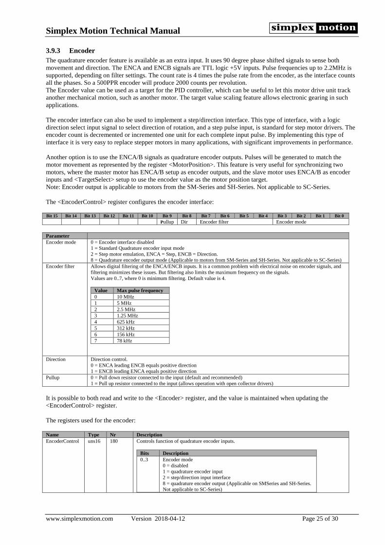
Simplex Motion Technical Manual
www.simplexmotion.com Version 2018-04-12 Page 25 of 30
3.9.3 Encoder
The quadrature encoder feature is available as an extra input. It uses 90 degree phase shifted signals to sense both
movement and direction. The ENCA and ENCB signals are TTL logic +5V inputs. Pulse frequencies up to 2.2MHz is
supported, depending on filter settings. The count rate is 4 times the pulse rate from the encoder, as the interface counts
all the phases. So a 500PPR encoder will produce 2000 counts per revolution.
The Encoder value can be used as a target for the PID controller, which can be useful to let this motor drive unit track
another mechanical motion, such as another motor. The target value scaling feature allows electronic gearing in such
applications.
The encoder interface can also be used to implement a step/direction interface. This type of interface, with a logic
direction select input signal to select direction of rotation, and a step pulse input, is standard for step motor drivers. The
encoder count is decremented or incremented one unit for each complete input pulse. By implementing this type of
interface it is very easy to replace stepper motors in many applications, with significant improvements in performance.
Another option is to use the ENCA/B signals as quadrature encoder outputs. Pulses will be generated to match the
motor movement as represented by the register <MotorPosition>. This feature is very useful for synchronizing two
motors, where the master motor has ENCA/B setup as encoder outputs, and the slave motor uses ENCA/B as encoder
inputs and <TargetSelect> setup to use the encoder value as the motor position target.
Note: Encoder output is applicable to motors from the SM-Series and SH-Series. Not applicable to SC-Series.
The <EncoderControl> register configures the encoder interface:
Bit 15 Bit 14 Bit 13 Bit 12 Bit 11 Bit 10 Bit 9 Bit 8 Bit 7 Bit 6 Bit 5 Bit 4 Bit 3 Bit 2 Bit 1 Bit 0
Pullup Dir Encoder filter Encoder mode
Parameter
Encoder mode 0 = Encoder interface disabled
1 = Standard Quadrature encoder input mode
2 = Step motor emulation, ENCA = Step, ENCB = Direction. 8 = Quadrature encoder output mode (Applicable to motors from SM-Series and SH-Series. Not applicable to SC-Series)
Encoder filter Allows digital filtering of the ENCA/ENCB inputs. It is a common problem with electrical noise on encoder signals, and
filtering minimizes these issues. But filtering also limits the maximum frequency on the signals.
Values are 0..7, where 0 is minimum filtering. Default value is 4.
Value Max pulse frequency
0 10 MHz
1 5 MHz
2 2.5 MHz
3 1.25 MHz
4 625 kHz
5 312 kHz
6 156 kHz
7 78 kHz
Direction Direction control.
0 = ENCA leading ENCB equals positive direction 1 = ENCB leading ENCA equals positive direction
Pullup 0 = Pull down resistor connected to the input (default and recommended)
1 = Pull up resistor connected to the input (allows operation with open collector drivers)
It is possible to both read and write to the <Encoder> register, and the value is maintained when updating the
<EncoderControl> register.
The registers used for the encoder:
Name Type Nr Description
EncoderControl uns16 180 Controls function of quadrature encoder inputs.
Bits Description
0..3 Encoder mode
0 = disabled 1 = quadrature encoder input
2 = step/direction input interface
8 = quadrature encoder output (Applicable on SMSeries and SH-Series. Not applicable to SC-Series)

Simplex Motion Technical Manual
www.simplexmotion.com Version 2018-04-12 Page 26 of 30
4..7 Encoder filter
Sets encoder signal filtering 0..7. Default value is 4.
8 Invert direction if set to 1
9 Enable pull up resistor if set to 1. There is a weak pull down resistor
when set to 0 (default).
Encoder int32 184/185 Value from quadrature encoder interface. Counts 4 * pulse frequency from encoder.
In case Encoder mode = 1 (step motor emulation) this register holds the counter value from the
step/dir interface instead.
3.10 Indicator LED
There is an indicator light on the unit. This indicator shows the current status of the device according to: Indicator Status
Steady Green Power is on, motor is off or standstill.
Blinking Green Motor is moving or torque is applied. The blink frequency increases with motor speed. The color starts
shifting towards yellow and red when the torque increases to high values.
Short yellow blink can be several reasons:
o The mode register is changed.
o The non volatile memory is written
Red light with yellow blinks Error state. The number of consecutive yellow blinks indicate which status bit caused the error. This table shows the error cause:
Nr of blinks Description
1 Internal fault in the unit
2 USB or Modbus communication error
3 Motor current is too high
4 Supply voltage too low or too high
5 Temperature is too high
6 Motor torque is above set threshold
7 Shaft is locked (power applied but not moving)
8 The regulator has a large error, <RegErrorMax> > <RegError>
9 Motor is rotating, speed > 0.1rps
10 Motor is rotating in reverse direction
11 Target reached when ramping position control
12 For future use
13 Digital input, specified by the <StatusInputs> register.
14 Digital input, specified by the <StatusInputs> register.
15 For user application, set by event handler.
16 For user application, set by event handler.
Note that several of these cases are not typical errors, but all status bits can be configured to set the
motor in error state.

Simplex Motion Technical Manual
www.simplexmotion.com Version 2018-04-12 Page 27 of 30
4 Protection and error handling There are a number of protection features to minimize the risks of damaging the unit while still allowing full use of the
performance. The main features are:
• Hardware overcurrent protection on motor current. This is the only error that can not be masked out, it will
always trip the driver and cause shutdown. This protection can be compared with a fuse – It should not be
activated by normal operation.
• Torque limit. The motor output torque is always limited to a user settable value. This limit should be set
according to the application.
• Over/under voltage. The hardware includes a protection diode that conducts current when the input supply
voltage is above +30V to protect the circuitry from damage. If large amounts of currents are supplied the
protection diode will be damaged. This can be the case when braking large inertia loads, as all the energy
is then output to the power supply, raising its voltage level. Over/under voltages can also trip the driver if
requested. The present supply voltage is continuously measured and available in the <Supply> register.
• Temperature. The electronics include a temperature sensor, and by use of a thermal motor model the
motor winding temperature is estimated. Both these temperatures are available through registers, and can
also trip the driver if requested.
• Locked shaft. If no movement on the motor shaft is detected even though it is fed with significant current,
a status bit is set. This could indicate a serious fault and can trip the driver if requested.
• Regulator error. The register <RegError> continuously shows the difference between actual and target
values for the regulator. If this vale exceeds the value in the <RegErrorMax> register a status bit is set.
This can trip the driver as well.
Status information from the unit is available through the <Status> register. Some bits indicate errors while others are
more of informational use. These status bits are only active as long as the error cause is active. To ensure that no status
events are missed there is also a latched version of the status register, <StatusLatched>. This register keeps status bits
active until they are cleared by the user.
The <Status> register also holds the current status of two inputs. These inputs are selected from the available digital
inputs by use of register <StatusInputs>. It is also possible to filter these inputs to suppress noise. This feature is useful
for implementing driver shutdown from limit switches to avoid mechanical damage in a setup with limited travel.
To enable stopping of the motor driver upon errors, what is frequently termed ‘driver trip’, there are two mask registers
that selects which status bits to monitor. If the same bit position in this mask register and the <Status> register is active
at the same time the system enters the failure mode. There are two such modes:
Mode Status mask register Description
Quickstop MaskQuickstop The motor stops in a controlled fashion, usually be braking the motor with <RampDecMax>
deceleration. The <Mode> register is changed to ‘QuickStop’. The indicator shows a normal stop indication – A steady green light.
Shutdown MaskShutdown The driver turns off the motor current immediately, and if the motor was running it will
continue to spin freely to a halt. The <Mode> register is set to ‘Shutdown’ and the indicator will show an error state where a blinking pattern indicates the source of shutdown.
The <Mode> register needs to be updated to bring the device out of the error state. Thus by setting the mask register the
user can select what type of errors should trip the driver.
If more flexibility is needed, such as driver trip on a special error code, it is possible to use the User1..2 status bits that
can be set using the event handler (see 3.7).
To provide further detail on error causes, the unit also generates error codes. These codes are 16bit with the top 4 bits
equal to the status bit number to which they belong. So for example the error codes for communication errors are in the
range hex[1001-1FFF]. A complete list of error codes can be found in section 4.1.
Nr Type Name Description Range:
410 uns16 Status Drive status. Each bit has status information according to the table below. This status word is used for several things, it can trip the driver, start
recording data or enable outputs. The bits are only active while the condition
is true.
Bit Name Description
0 Fail Internal error in the driver
1 Communication Communication error
2 Current Hardware overcurrent protection triggered.
Input current > 40A
0..65535

Simplex Motion Technical Manual
www.simplexmotion.com Version 2018-04-12 Page 28 of 30
3 Voltage Input voltage is too high or low
Voltage < 15V or Voltage > 30V
4 Temperature Temperature of drive is too high, motor temp
> 120°C or electronics temp > 100°C.
5 Torque Motor torque limit active
6 Locked Shaft is locked (power applied but not moving)
7 Regulator The regulator has a large error,
<RegErrorMax> > <RegError>
8 Moving Motor is rotating Speed > 0.1rps
9 Reverse Motor is rotating in reverse direction
10 Target Target reached when ramping position
control
11 Reserved For future use
12 InputA Digital input, specified by the <StatusInputs>
register.
13 InputB Digital input, specified by the <StatusInputs>
register.
14 User1 For user application, set by event handler.
15 User2 For user application, set by event handler.
411 uns16 StatusLatched A latched version of the <Status> register. The corresponding bit in this register is set when it is set in the <Status> register, and then kept set until it
is overwritten by the user.
0..65535
412 uns16 StatusInputs This register defines two digital inputs that are available in the status register as InputA and InputB. This is useful for Limit switches that should cause a
driver shutdown. It is also possible to filter these inputs from noise.
Bits Description
0..3 Input number to use for InputA.
0 = IN1, 1 = IN2 etc
4..7 Input number to use for InputB 0 = IN1, 1 = IN2 etc
8..15 Filter value. 0 = no filtering. Increasing values causes
more filtering and larger delay.
413 uns16 MaskQuickstop This is a 16 bit mask that defines which status bits that should cause a quick
stop of the motor. A one in a bit position enables that status bit source.
414 uns16 MaskShutdown This is a 16 bit mask that defines which status bits that should trip the driver (enter error mode). A one in a bit position enables that status bit source.
0..65535
415 uns16 Error This register holds the latest generated error code. 0..65535
420/421 uns32 Time Tracks time as 4096 counts per second. Wraps around after about 12 days. 0 .. 4294967295

Simplex Motion Technical Manual
www.simplexmotion.com Version 2018-04-12 Page 29 of 30
4.1 List of error codes
These are the defined error codes that can be read from the <Error> register. The register content indicate the latest
error, but the error cause may not any longer be existing when the register is read.
Error code (hexadecimal) Description
0x0001 General internal error
0x0002 Internal software timing error
0x0003 Error in application code, not terminating.
0x1001 General communication error
0x1002 Reference to invalid register number
0x1101 Modbus parity error
0x1102 Modbus framing error
0x1103 Modbus overrun error
0x1104 Modbus checksum error
0x1105 Modbus illegal function code
0x1106 Modbus illegal diagnostics function code
0x2001 Hardware overcurrent protection triggered
0x3001 Supply voltage too low
0x3002 Supply voltage too high
0x4001 Temperature of electronics is too high
0x4002 Temperature of motor winding is too high
0x5001 Torque limiting is active
0x6001 Locked shaft condition detected
0x7001 Regulator error is large
4.2 Hardware reset of registers
If there is a need to resets all parameters to factory default settings and you are unable to reach the <Mode> registers
factory reset mode, there is a way of doing a hardware reset to factory default settings. If connecting IN5 directly to IN7
at power on from power off, the motor will be set to factory default settings. In the same way you can put the motor in
firmware mode by connecting IN5 with IN6.

Simplex Motion Technical Manual
www.simplexmotion.com Version 2018-04-12 Page 30 of 30
5 Power supply considerations and EMC The power supply used with the servomotor has to be able to supply enough current for the application, not only for the
continuous operation, which is typically up to 6A current, but also for the instantaneous higher output power during for
example high accelerations.
For applications that use high braking deceleration rates, especially with high inertia loads, the power supply unit must
also be able to sink current, since the motor then operates as a generator and outputs current to the power supply.
Failure to sink this current will raise the supply voltage, potentially to damaging levels. External protection zener diodes
can be used to handle short bursts of overvoltage, se table below.
The <Supply> register contains the real time supply voltage and this can be monitored during motion to verify that the
voltage level is not raised too high. There is also a status bit in the <Status> register that indicates high voltage
conditions
Motor rated voltage Recommended external protection zener diodes rating
+12V 14-16V
+24V 25-30V
+48V 50-60V
Also note that the grounding potential at the motor unit will change if there are long cables and high currents because of
cable resistance. Since the motor input/outputs share the same grounding potential as the power supply, they are
affected accordingly. This issue is handled by using thicker cables or by using the motor ground as the central
grounding point (star grounding).
EMI issues are common for motor control installations. The switching of the motor currents creates fast transients in
both voltage and current waveforms that typically spread out to surrounding equipment. One of the most problematic
sources of noise radiation is usually the cabling between the controller and the motor. But this issue is of no concern
here since the electronics and the motor are integrated into the same enclosure with a minimum of cabling. Generally
EMI problems are non existent in integrated drive units. But there is one issue left even for these types of
implementations. The switching motor currents propagate out on the power supply cabling as well. So there will always
be some noise conducted from the device to the power supply unit, and potentially radiated from the cable. In this
product that noise is suppressed by two means:
• A high order low pass filter to minimize the noise above 150kHz
• Spread spectrum techniques to spread out the noise energy across a continuous range of frequencies. This
limits the energy at each individual frequency.
Simples Motions motor units will pass the requirements from the IEC/EN61800-3 standard for the industrial
environment. To also pass the requirements for the residential/commercial environment an external filter will have to be
used on the power supply input. This can typically be a simple LC filter consisting of a 10uH inductor in series with the
positive supply rail and a 100uF low ESR capacitor across the power supply feed. Both components should be located
close to the SimplexMotion unit.