simplified design procedure for reinforced …¬ed design procedure for reinforced concrete columns...
TRANSCRIPT

Simplified Design Procedure for Reinforced Concrete Columns Basedon Equivalent Column Concept
Hamdy M. Afefy1),*, and El-Tony M. El-Tony2)
(Received December 11, 2015, Accepted February 13, 2016, Published online March 11, 2016)
Abstract: Axially loaded reinforced concrete columns are hardly exist in practice due to the development of some bending
moments. These moments could be produced by gravity loads or the lateral loads. First, the current paper presents a detailed
analysis on the overall structural behavior of 15 eccentrically loaded columns as well as one concentrically loaded control one.
Columns bent in either single curvature or double curvature modes are tested experimentally up to failure under the effect of
different end eccentricities combinations. Three end eccentricities ratio were studied, namely, 0.1b, 0.3b and 0.5b, where b is the
column width. Second, an expression correlated the decay in the normalized axial capacity of the column and the acting end
eccentricities was developed based on the experimental results and then verified against the available formula. Third, based on
the equivalent column concept, the equivalent pin-ended columns were obtained for columns bent in either single or double
curvature modes. And then, the effect of end eccentricity ratio was correlated to the equivalent column length. Finally, a
simplified design procedure was proposed for eccentrically loaded braced column by transferring it to an equivalent axially
loaded pin-ended slender column. The results of the proposed design procedure showed comparable results against the results of
the ACI 318-14 code.
Keywords: columns, double curvature mode, eccentric loading, equivalent column concept, single curvature mode,
reinforced concrete.
1. Introduction
Eccentrically loaded reinforced concrete columns arecommonly exist in practice due to the existence of somebending moments. The eccentricity of the supported beamsas well as the unavoidable imperfections of construction arethe main sources of the developed bending moments in thecolumns under gravity loads. In addition, lateral loads due towind or earthquake loading are another source of thedeveloped bending moments on the columns. Therefore, thestrength of the columns is controlled by the compressivestrength of concrete, the tensile strength of the longitudinalreinforcements and the geometry of the column’ cross-sec-tion (Park and Paulay 1975; Nilson 2004; McCormac 1998;Yalcin and Saatcioglu 2000; MacGregor and Wight 2009).Contrasting to reinforced concrete beams, the compressionfailure cannot be avoided for eccentrically loaded columnssince the type of failure is mainly dependent on the axialload level (Park and Paulay 1975).
Reinforced concrete columns are classified as short col-umns while the slenderness effect can be neglected orslender columns where the slenderness effect has to beincluded in the design. In order to distinguish between thesetwo types, there are two important limits for slendernessratio/index which are the lower and the upper slendernesslimits. Most of the limit expressions provided by codes werederived assuming a certain loss of the column ultimatecapacity due to the second order effect. Lower slendernesslimits may be defined as the slenderness producing a certainreduction, usually 5–10 %, in the column ultimate capacitycompared to that of a non-slender column (Mari andHellesland 2005). Inspite that the lower slenderness limit ofshort column is mostly dependent on the adopted designstandards. Figure 1 shows comparison among the limitingslenderness indices stipulated by the American ConcreteInstitute Code, ACI 318-14 (2014), the Canadian StandardCode, CSA A23.3-04 (R 2010) and the Egyptian Code ofPractice, ECP 203-2007 (2007), where He is the effectivelength of the column and i is the radius of gyration of thecolumn cross-section. It can be noted that the limit stipulatedby the ACI 318-14 depends on the relative end moments,while the limit adopted by the CSAA23.3-04 depends on boththe end moments ratio and the axial load level. On the otherhand, the ECP 203-07 adopts a fixed limit for the upperslenderness limit for the short column regardless of the endmoments, the axial load level and the concrete strength, inorder to distinguish between the short and the slender column.
1)Department of Structural Engineering, Faculty of
Engineering, Tanta University, Tanta 31511, Egypt.
*Corresponding Author; E-mail:
[email protected])Department of Structural Engineering, Faculty of
Engineering, Alexandria University, Alexandria, Egypt.
Copyright � The Author(s) 2016. This article is published
with open access at Springerlink.com
International Journal of Concrete Structures and MaterialsVol.10, No.3, pp.393–406, September 2016DOI 10.1007/s40069-016-0132-0ISSN 1976-0485 / eISSN 2234-1315
393

As for the upper slenderness limit, there is no explicitdefinition for that limit at most of the design standards(American Concrete Institute 2014; CAN/CSA-A23.3-04(R2010) 2010; ECP 203-2007). In addition, the amount ofreduction in the column capacity corresponding to that limitis not well defined. Although the upper slenderness limit canbe considered as the limit required to avoid instability failureof the column (Ivanov 2004; Barrera et al. 2011). Despitethis common basis, and even though most relevant factorsgoverning the behavior of slender columns are well identi-fied, a lack of uniformity can be observed in the conceptualtreatment of the lower/upper slenderness limits in differentcodes. Not surprisingly, large differences may be obtainedwhen applying the above code provisions. Also, there are
different values of the lower/upper slenderness limits forcolumns based on the bracing conditions.In this paper the proposed design approach is aimed to
consider any imperfection on the original column as well asthe acting end moments when designing the column. Thatcan be done be transforming the original column consideringany initial bending moments to an equivalent pin-endedaxially loaded column. And then, the additional bendingmoment including the end eccentricities as well as slender-ness effect can be calculated. Therefore, the lower slender-ness ratio could be bypassed. In addition, in order to verifythe instability failure of the column, the acting axial load onthe equivalent column is compared with the critical bucklingload of the column.Hinged-ended columns braced against side-sway may be
bent in either single or double curvature mode with loadingdepending on the direction of acting end moments asdepicted in Fig. 2 (Park and Paulay 1975; Cranston 1972).For both curvature modes, the bending deformations causeadditional bending moments that can affect the primary endmoments. If the additional moments are large, the maximummoments may move from ends to within the height of thecolumns. Since the lateral deformation for the case of singlecurvature mode is greater than that of the double curvaturemode, the maximum bending moment in the single curvaturecase is higher than that in the double curvature one (Park andPaulay 1975). Therefore, the greatest reduction in the ulti-mate load capacity will occur for the case of equal endeccentricities for columns bent in single curvature mode,while the smallest reduction will occur for the case of equalend eccentricities for columns bent in double curvature mode(MacGregor et al. 1970; Milner et al. 2001).It is accepted that the deflected axis of any column may be
represented by a portion of the column deflected shape of
0
10
20
30
40
50
60
-0.5 0 0.5 1
Slen
dern
ess
inde
x, H
e/i
Relative end moment ratio, M2/M1
ECP 203-2007CSA-A23.3-04 ICSA-A23.3-04 IIACI 318-14
1' =gcf AfP
5.0' =gcf AfP
Fig. 1 Limitations of the upper slenderness limits for shortcolumn stipulated in different standards.
(a) Single curvature (b) Double curvature
Fig. 2 Curvature modes of RC columns under end eccentric loading.
394 | International Journal of Concrete Structures and Materials (Vol.10, No.3, September 2016)

axially loaded pin-ended column (Chen and Lui 1987).Therefore, for a given column subjected to end moments, anequivalent column exists. Making use of Fig. 2, the columndeflected shape of the equivalent pin-ended column can berepresented by sinusoidal curve as illustrated in Eq. (1).
e ¼ eo sinp xH� ð1Þ
where e is the lateral deflection of the column at a distance xfrom one end of the column, H* is the length of theequivalent pin-ended column and eo is the maximumdeflection at the mid-height of the equivalent column thatcan be calculated using Eq. (2).
eo ¼ /m
H�2
p2ð2Þ
where /m is the curvature of the column based on the col-umn’s mode of failure.This concept is adopted in order to reduce uni-axially
loaded column to an axially loaded equivalent pin-endedcolumn with greater length (El-Metwally 1994; Afefy et al.2009; Afefy 2012).In the current paper, the behavior of eccentrically loaded
column bent in both single and double curvature modes isstudied experimentally. In addition, based on the experi-mental test results, an expression was derived in order topredict the capacity lost due to column end eccentricities.And then, the equivalent column concept is employed inorder to switch eccentrically loaded columns bent in eithersingle or double curvature mode to axially loaded pin-endedequivalent columns. The end eccentricity ratio is correlatedto the equivalent column length. Finally, a simplified designprocedure for eccentrically loaded braced columns is pro-posed and compared against the design procedure stipulatein the ACI 318-14 Code.
2. Experimental Work Program
2.1 Test ColumnsThe experimental work program included 15 reduced-
scale columns (1/3 scale model) divided into 4 groups aswell as a control axially loaded column. The first two groupsrepresented columns bent in single curvature modes, whilethe remaining two groups represented columns bent indouble curvature modes. For both curvature modes, equaland unequal end eccentricities combinations about minoraxis were studied.The nominal axial capacity of the column cross-section
was about 600 kN based on Eq. (3) as recommended by ACI318-14.
Po ¼ 0:85f 0c Ac � Asð Þ þ Asfy ð3Þ
where Po is the nominal axial capacity of the column cross-section, f 0c is the concrete compressive cylinder strength, fy isthe yield strength of the longitudinal steel bars, Ac is the
cross-sectional area of concrete section, and As is the cross-sectional area of the longitudinal steel bars.It was noted that the usual end eccentricity value, e/b, for
columns in reinforced concrete buildings is varying from 0.1to 0.65 (Mirza and MacGregor 1982). In addition, recentresearches showed that exposing the reinforced concretecolumn to an end eccentricity ratio more than half the col-umn side exhibited drastic reduction in the ultimate capacityof the column (MacGregor et al. 1970; Milner et al. 2001;Chuang and Kong 1997; Afefy 2007). Hence, the studiedend eccentricity ratios were chosen to be 0.1, 0.3 and 0.5.Table 1 summarizes the details of the tested columns. The
column cross-section was 100 mm width by 150 mm lengthand the overall height of 1200 mm. The column longitudinalreinforcement was four deformed bars of 10 mm diametercorresponding to reinforcement ratio of 2.09 %. The stirrupswere made from mild smooth bars of 6 mm diameter spacedevery 100 mm, while both ends were provided by additionalstirrups as depicted in Fig. 3a.All specimens were cast horizontally in wooden forms. Two
days after casting, the standard cubes and the sides of thespecimens were stripped from the molds and covered withplastic sheets until the seventh day, when the plastic sheetswereremoved and the specimens allowed air-drying until testing day.
2.2 Material PropertiesThe used concrete was normal strength concrete of
40 MPa target cube strength, which was the average of threestandard cubes of 150 mm side length. The cement used wasnormal Portland cement (Type I) with 4.75 kN/m3 cementcontent and the water to cement ratio was kept as 0.38. Theconcrete mix contained type I crushed pink limestone as thecoarse aggregates whose maximum aggregate size was10 mm. The sand was supplied from a local plant around thesite and its fineness modulus was 2.7 %. The volumes oflimestone and sand in one cubic meter were 0.73 and 0.37,respectively. The average concrete strength at the testing dayof columns was 42.89 MPa, while the test of all columns hadbeen carried out in two consecutive days.In order to determine the mechanical properties of the
longitudinal deformed steel bars of 10 mm diameter as wellas the transverse smooth bars of 6 mm diameter, tensile testswere performed on three specimens for each bar size. For the10 mm deformed bars, the mean value of tensile yieldstrength, ultimate strength and Young’s modulus were418 MPa, 580 MPa and 202 GPa, respectively, while therelevant values for the 6 mm mild steel bars were 250 MPa,364 MPa and 205 GPa, respectively. The used steel to formthe pile caps in order to facilitate the application of eccentricloading at both ends of columns was mild steel of 12 mmthickness and yield strength of 280 MPa.
2.3 Test Setup and InstrumentationSteel rig had been fabricated and assembled at the Rein-
forced Concrete Laboratory of the Faculty of Engineering,Alexandria University, Alexandria, Egypt, in order to facil-itate the execution of the experimental work program. Steel
International Journal of Concrete Structures and Materials (Vol.10, No.3, September 2016) | 395

caps were provided at both ends of the column in order todistribute the column compression load at both ends as wellas to facilitate the application of eccentric loading. Fig-ures 3b and 3c show both supports, while the column wasloaded using compression test machine of 3000 kN capacity.Five 100 mm LVDTs were used in order to measure the
lateral deformation about the minor axis as depicted inFig. 3. Hence, the final deformed shape can be obtained. Inaddition, 2 strain gauges of 6 mm gauge length weremounted on the mid-height of the column longitudinal barsin order to measure the developed normal strain at the mid-height section. Load was applied in a force-control protocol
Table 1 Test matrix.
Group no. Column Eccentricity at upper end Eccentricity at lower end Curvature mode
mm e/b mm e/b
Control C-0-0 0.0 0..0 0.0 0.0
1 S-1-1 10 0.1 10 0.1 Single
S-3-3 30 0.3 30 0.3
S-5-5 50 0.5 50 0.5
2 S-0-1 10 0.1 0.0 0.0
S-1-3 30 0.3 10 0.1
S-1-5 50 0.1 10 0.5
S-0-3 30 0.3 0.0 0.0
S-3-5 50 0.5 30 0.3
S-5-0 50 0.5 0.0 0.0
3 D-1-1 10 0.1 10 0.1 Double
D-3-3 30 0.3 30 0.3
D-5-5 50 0.5 50 0.5
4 D-1-3 30 0.3 10 0.1
D-1-5 50 0.5 10 0.1
D-3-5 50 0.5 30 0.3
Fig. 3 Concrete dimensions, reinforcement detailing and supports details for typical column.
396 | International Journal of Concrete Structures and Materials (Vol.10, No.3, September 2016)

to the column through moving lower head of the testingmachine incrementally every 5 kN. The loading was con-tinued until the specimen cannot sustain further loading.After each loading step, the acting loads on the column, thestrain gauges readings and the LVDTs readings were recor-ded. An automatic data logger unit had been used in order torecord and store data during the test for load cells, straingauges and the LVDTs.
2.4 Specimen NomenclatureTable 1 presents test parameters and the associated spec-
imen descriptions. The specimen nomenclature consists of 3symbols separated by hyphens. The first symbol indicatesthe curvature mode (S = single curvature, D = doublecurvature). The second nomenclature stands for amount oflower end eccentricity (0 = concentric loading, 1 = 10 mmend eccentricity, 3 = 30 mm end eccentricity, 5 = 50 mmend eccentricity). The third number indicates the same endeccentricity as presented in the second nomenclature but forthe upper end. For instance, S-1-5 can be interpreted asfollows: S = single curvature; 1 = the eccentricity at lowerend = 10 mm; 5 = the eccentricity at the upperend = 50 mm.
3. Results and Discussion
The test results of the concentrically loaded column aswell as eccentrically loaded columns under the effect ofdifferent end eccentricities combinations are presented anddiscussed in detailed. In general, all eccentrically loadedcolumns sustained ultimate loads lower than that sustainedby the concentrically loaded column. In addition, the ulti-mate load reduction for columns bent in single curvaturemodes were higher than those of the columns had the sameend eccentricities but bent in double curvature modes. Asummary of the test results is given in Table 2 and furtherdiscussed is presented including modes of failure, deformedshapes, ultimate capacity and developed normal strain on thelongitudinal bars at the mid-height section.
3.1 Modes of FailureThe failure of axially loaded column C-0-0 was sudden
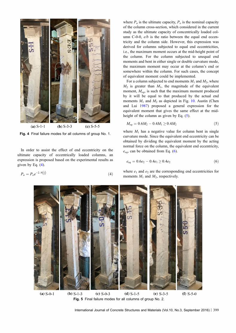
compressive failure since after yielding of the longitudinalsteel bars in compression, the concrete had been crushed atthe upper half of the column. The application of equal endeccentricities as for columns S-1-1, S-3-3 and S-5-5 resultedin employing constant moment along the entire height of thecolumn. For columns S-1-1 and S-3-3, cracks began toappear very close to the ultimate load near the mid-heightsection. On the other hand, increasing the end eccentricity tobe 0.5b resulted in regular flexural failure. For column S-5-5,cracks began to appear at the tensile side at acting load ofabout 62 % of the failure load. With further loading, cracksspread on the tensile side till the concrete crushed at thecompression side near the mid-height section. Figure 4shows the failed columns of group No. 1.
For the case of unequal end eccentricities, failure waseither regular tension failure or sudden flexural failure(compression failure). Cracks began to appear near the endsupport of the higher end eccentricity, and then failure wastriggered by concrete crushing at such support. For all casesof end eccentricity of 0.5b, cracks appeared at the tensionside near the end support at acting load of about 82 % of thefailure load, while for other end eccentricities (0.1b and0.3b) cracks appeared at a vertical load very close to thefailure load. Figure 5 depicts the failure shapes for all col-umns of group No. 2.For all columns bent in double curvature mode, failures
were similar to the case of single curvature modes withunequal end eccentricities where all columns failed near theend support of the higher end eccentricity in flexural modeof failure. Figures 6 and 7 show the failure shapes for allcolumns of groups No. 3 and No. 4. It can be noted thatcolumn bent in double curvature mode sustained higher loadthan the opponent column bent in single curvature mode. Forinstance, columns D-1-3, D-1-5, and D-3-5 sustained ulti-mate loads of 480, 300, and 379 kN, respectively, whilecolumns S-1-3, S-1-5 and S-3-5 sustained ultimate loads of395, 245, and 220 kN, respectively. That can be attributed tothat the section of the maximum lateral deformation due toaxial compression is around the mid-height point, while thislocation has minimal effect of bending moment for columnbent in double curvature mode. On the other hand, for col-umn bent in single curvature mode, this location, mid-heightsection, has considerable bending moment, which magnifiesthe primary moment on the column leading to lower sus-tained load.
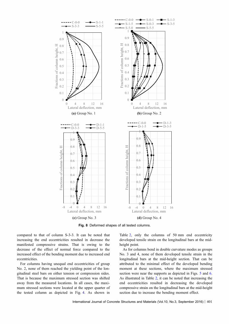
3.2 Deformed ShapesThe measured deformed shapes about minor axis for all
columns near failure are depicted in Fig. 8. Figures 8a, bshow the deformed shapes for columns bent in single cur-vature modes. It can be noted that inspite the column C-0-0was consider as short column it exhibited slight lateraldeformation of about 0.03b. This value is within the limitsstipulated by the Egyptian Code of Practice, ECP 203-2007.This limit states that the upper limit for short column in orderto neglect the slenderness effect is 0.05b. Increasing theequal end eccentricities to be 10 mm (S-1-1) resulted inincreased the measured lateral deformation by about0.05b compared to that of the axially loaded column (C-0-0).Increasing the end eccentricities to be 30 mm (S-3-3)resulted in increased lateral deformation by about 0.06b. In-creasing the end eccentricities further to 50 mm (S-5-5)resulted in increased lateral deformation by about 0.12b. Themeasured lateral deformations of all columns having equalend eccentricities and bent in single curvature mode wereapproximately symmetrical about the mid-height point asdepicted in Fig. 8a. As for the case of unequal end eccen-tricities, the maximum value for the measured lateraldeformation was bias to the end having the higher endeccentricity as depicted in Fig. 8b. For the case of columnsbent in single curvature mode, the upper bound was
International Journal of Concrete Structures and Materials (Vol.10, No.3, September 2016) | 397

exhibited by column S-5-5, while the lower bound wasmanifested by axially loaded column C-0-0.For columns bent in double curvature mode, it can be
noted that the columns showed un-symmetric deformedshape compared to initial center line of the column. How-ever, when consider the final deformed shape due to axialload as exhibited by column C-0-0, the final deformedshapes showed symmetric configuration with respect to thedeformed shape of column C-0-0, for the case of equal endeccentricities as depicted in Fig. 8c. As for unequal endeccentricities, the maximum lateral deformations were shif-ted to the end having the higher end eccentricity as shown inFig. 8d.Figure 9a shows the relationships between the vertical
load and the developed lateral deflection at the mid-heightsection for all columns of Group No. 1. It can be noted thatincreasing the end eccentricity ratio resulted in decreasingthe ultimate load carrying capacity and increasing the cor-responding lateral defection. The column S-5-5 showed thehighest reduction in the ultimate capacity as well as thehighest lateral deflection among all columns subjected todifferent end eccentricity combinations and bent in eithersingle or double curvature modes as depicted in Figs. 9b, c.
For columns having unequal end eccentricity combina-tions bent in single curvature modes and the columns bent indouble curvature modes the maximum lateral deflectionswere noticed to be developed at the upper half of the col-umns as shown in Fig. 8. Therefore, the lateral deflectionsfor those columns were presented at a distance 0.67 of thecolumn height as depicted in Figs. 9b and 9c. It can beobserved that the columns bent in double curvature modesshowed higher ultimate capacity and lower lateral defectionsthan those of columns bent in single curvature modes andhaving the same end eccentricities combinations.
3.3 Ultimate CapacityTable 2 summarizes the ultimate sustained loads for all
columns. It can be noted that the highest ultimate capacityexhibited by the concentrically loaded column C-0-0, whilethe lowest ultimate capacity was achieved by column S-5-5having single curvature mode and equal end eccentricities of0.5b, as expected. The column S-5-5 sustained only 25 % ofthe relevant capacity of concentrically loaded column C-0-0.This means that with further end eccentricity the column willdrop its normal capacity significantly.
Table 2 Experimental results.
Group no. Column Cracking load,kN
Failure load, kN Maximum measured steel strain atmid-height, micro-strain
Maximum lateraldeflection, mm
Dominant modeof failure
Compressive Tensile
Control C-0-0 NA 675 2247 NA 3.06 Suddencompressive
1 S-1-1 NA 450 2326 NA 7.72 Compressionfailure
S-3-3 270 300 2063 3453 8.91 Tension failure
S-5-5 105 170 980 2362 14.77 Tension failure
2 S-0-1 NA 530 1982 NA 2.72 Compressionfailure
S-1-3 NA 395 1809 NA 8.47 Compressionfailure
S-1-5 210 245 1103 474 7.60 Tension failure
S-0-3 NA 410 1612 NA 4.04 Compressionfailure
S-3-5 180 220 1157 958 11.37 Tension failure
S-5-0 220 265 856 446 5.65 Tension failure
3 D-1-1 NA 580 1460 NA 2.82 Compressionfailure
D-3-3 300 473 1004 NA 5.40 Tension failure
D-5-5 250 416 528 NA 4.90 Tension failure
4 D-1-3 NA 480 1321 NA 2.56 Compressionfailure
D-1-5 180 300 905 NA 5.77 Tension failure
D-3-5 240 379 569 NA 4.57 Tension failure
NA not applicable.
398 | International Journal of Concrete Structures and Materials (Vol.10, No.3, September 2016)
In order to assist the effect of end eccentricity on theultimate capacity of eccentrically loaded columns, anexpression is proposed based on the experimental results asgiven by Eq. (4).
Pu ¼ Poe�2::9 e
bð Þ ð4Þ
where Pu is the ultimate capacity, Po is the nominal capacityof the column cross-section, which considered in the currentstudy as the ultimate capacity of concentrically loaded col-umn C-0-0, e/b is the ratio between the equal end eccen-tricity and the column side. However, this expression wasderived for columns subjected to equal end eccentricities,i.e., the maximum moment occurs at the mid-height point ofthe column. For the column subjected to unequal endmoments and bent in either single or double curvature mode,the maximum moment may occur at the column’s end orsomewhere within the column. For such cases, the conceptof equivalent moment could be implemented.For a column subjected to end moments M1 andM2, where
M2 is greater than M1, the magnitude of the equivalentmoment, Meq, is such that the maximum moment producedby it will be equal to that produced by the actual endmoments M1 and M2 as depicted in Fig. 10. Austin (Chenand Lui 1987) proposed a general expression for theequivalent moment that gives the same effect at the mid-height of the column as given by Eq. (5).
Meq ¼ 0:6M2 � 0:4M1 � 0:4M2 ð5Þ
where M1 has a negative value for column bent in singlecurvature mode. Since the equivalent end eccentricity can beobtained by dividing the equivalent moment by the actingnormal force on the column, the equivalent end eccentricity,eeq, can be obtained from Eq. (6).
eeq ¼ 0:6e2 � 0:4e1 � 0:4e2 ð6Þ
where e1 and e2 are the corresponding end eccentricities formoments M1 and M2, respectively.
Fig. 4 Final failure modes for all columns of group No. 1.
Fig. 5 Final failure modes for all columns of group No. 2.
International Journal of Concrete Structures and Materials (Vol.10, No.3, September 2016) | 399

Table 3 lists normalized capacities based on both experi-mental findings and those obtained from the proposedexpression. It can be noted that the coefficient of variationwas 0.0941. In addition, the maximum variation is rangingfrom -10 % to ?21 %, while in most cases small variationswere recorded. This indicated that the proposed expression
can predict well the ultimate capacities of eccentrically loa-ded columns bent in either single or double curvature modes.Furthermore, the proposed expression based on experi-
mental tests was compared with the proposed expression byAfefy (2012). Based on about 400 test results from literature,Afefy proposed Eq. (7) in order to correlate the normalizedaxial capacity and the end eccentricity ratio e/b.
Pu ¼ Poe�2:4 e
tð Þ ð7Þ
Figure 11 shows comparison between both expressions. Itcan be concluded that the proposed expression based onexperimental test results showed more conservative resultswithin about 10 % compared to that presented by Afefy(2012).
3.4 DevelopedNormalStrainon theLongitudinalBars at the Mid-height SectionInspite that the maximum stressed section was not the
same for all tested columns depending on the end eccen-tricities combinations, the developed normal strains on thelongitudinal bars were measured at the mid-height sec-tion. Based on the used steel type, the yield strain of thelongitudinal bars is 2069 micro-strain. Since the columnC-0-0 was short in both directions, i.e., the effect of slen-derness is minimal, the developed strains along the entireheight of the reinforcing bars should reach the yielding pointat failure. That happened, as expected, where the measuredcompressive strain near failure was 2247 micro-strain forcolumn C-0-0.The application of end eccentricities at column ends
changed the strain distribution along the column cross-sec-tion at the mid-height point, where tensile strain maybedeveloped based on the end eccentricity value as well as thecurvature mode. For columns bent in single curvaturemodes, tensile strain could be developed at the mid-heightsection since this section is the maximum stressed section forthe case of equal end eccentricities. While, for unequal endeccentricities, the maximum stressed section could be shiftedbased on the end eccentricities combinations. On the otherhand, for the columns bent in double curvature modes, themid-height section could develop the lowest strain for thecase of equal end eccentricities and higher values but not themaximum ones for the case of unequal end eccentricities.For group No. 1, only column S-1-1 developed compres-
sive strain along the entire cross-section with a maximumvalue exceeded the yielding strain (2326 micro-strain). Thiscan be attributed to small end eccentricities, which resultedin subjecting the column cross-section to non-uniformcompressive stress. Increasing the end eccentricity to30 mm, resulted in increasing the acting bending moment.Hence, tensile stress was developed and the measured tensilestrain exceeded the yielding point (3453 micro-strain).Increasing the end eccentricity further to 50 mm, showed thesame behavior as exhibited by column S-3-3 but the mea-sured tensile strain was lower than that developed by columnS-3-3 inspite that the acting moment was greater. That can beattributed to the lower sustained load by column S-5-5
Fig. 6 Final failure modes for all columns of group No. 3.
Fig. 7 Final failure modes for all columns of group No. 4.
400 | International Journal of Concrete Structures and Materials (Vol.10, No.3, September 2016)
compared to that of column S-3-3. It can be noted thatincreasing the end eccentricities resulted in decrease themanifested compressive strains. That is owing to thedecrease of the effect of normal force compared to theincreased effect of the bending moment due to increased endeccentricities.For columns having unequal end eccentricities of group
No. 2, none of them reached the yielding point of the lon-gitudinal steel bars on either tension or compression sides.That is because the maximum stressed section was shiftedaway from the measured locations. In all cases, the maxi-mum stressed sections were located at the upper quarter ofthe tested column as depicted in Fig. 4. As shown in
Table 2, only the columns of 50 mm end eccentricitydeveloped tensile strain on the longitudinal bars at the mid-height point.As for columns bend in double curvature modes as groups
No. 3 and 4, none of them developed tensile strain in thelongitudinal bars at the mid-height section. That can beattributed to the minimal effect of the developed bendingmoment at these sections, where the maximum stressedsection were near the supports as depicted in Figs. 5 and 6.As illustrated in Table 2, it can be noted that increasing theend eccentricities resulted in decreasing the developedcompressive strain on the longitudinal bars at the mid-heightsection due to increase the bending moment effect.
(a) Group No. 1 (b) Group No. 2
(c) Group No. 3 (d) Group No. 4
0
0.1
0.2
0.3
0.4
0.5
0.6
0.7
0.8
0.9
1
0 4 8 12 16
Frac
tions
of c
olum
n he
ight
, H
Lateral deflection, mm
C-0-0 S-1-1S-3-3 S-5-5
0
0.1
0.2
0.3
0.4
0.5
0.6
0.7
0.8
0.9
1
0 4 8 12 16
Frac
tions
of c
olum
n he
ight
, H
Lateral deflection, mm
C-0-0 S-0-1 S-1-3S-1-5 S-0-3 S-3-5S-5-0 S-5-5
0
0.1
0.2
0.3
0.4
0.5
0.6
0.7
0.8
0.9
1
-8 -4 0 4 8 12 16
Frac
tions
of c
olum
n he
ight
, H
Lateral deflection, mm
C-0-0 D-1-1D-3-3 D-5-5
0
0.1
0.2
0.3
0.4
0.5
0.6
0.7
0.8
0.9
1
-8 -4 0 4 8 12 16
Frac
tions
of c
olum
n he
ight
, H
Lateral deflection, mm
C-0-0 D-1-3D-1-5 D-3-5
Fig. 8 Deformed shapes of all tested columns.
International Journal of Concrete Structures and Materials (Vol.10, No.3, September 2016) | 401

3.5 Equivalent ColumnThe relationship between the equivalent pin-ended col-
umn, H*, and the end eccentricity is given in Eq. (1).Assuming balanced failure of the column, the curvature atthe mid-height section of the equivalent column, /m, can berepresented by Eq. (8).
/m ¼ ecu þ eyb� c
ð8Þ
where ecu is the concrete crushing strain = 0.003, ey is thesteel yield strain, equals yield stress divided by steelmodulus of elasticity, and c is concrete cover. Hence themaximum mid-height eccentricity can be rewritten as givenin Eq. (9).
eo ¼ecu þ eyb� c
� H�2
p2ð9Þ
Knowing the end eccentricity value as well as the curvaturemode, the equivalent column could be obtained.
3.5.1 Implementation of the Equivalent ColumnConcept on Column Bend in Single Curvature ModeConsider column S-3-5 as an example for column bent in
single curvature mode, the equivalent pin-ended axially loa-ded column is determined in the following, refer to Fig. 12a.
e ¼ eo sinp xH�
� �
eo ¼ecu þ eyb� c
� H�2
p2¼ 0:00000568H�2;
e2 ¼ 50 mm; e1 ¼ 30 mm
e1 ¼ 0:00000568H�2 sinp x1H�
� �¼ 30 ! ð1Þ
e2 ¼ 0:00000568H�2 sinp x2H�
� �¼ 50 ! ð2Þ
x2 ¼ x1 þ 1200 ! ð3Þ
Solving the three equations by trial and error yields
(a) Group No. 1 (b) Group No. 2 (c) Groups No. 3 and 4
0
100
200
300
400
500
600
700
0 4 8 12 16
Ver
tical
load
, kN
Mid-height lateral deflection, mm
C-0-0S-1-1S-3-3S-5-5
0
100
200
300
400
500
600
700
0 4 8 12 16
Ver
tical
load
, kN
Lateral deflection at 0.67H
from lower end, mm
S-0-1S-1-3S-1-5S-0-3S-3-5S-5-0
0
100
200
300
400
500
600
700
0 4 8 12 16
Ver
tical
load
, kN
Lateral deflection at 0.67H from lower end, mm
D-1-1D-3-3D-5-5D-1-3D-1-5D-3-5
Fig. 9 Vertical load versus lateral deflection for all tested columns.
Meq
Meq Meq
Mmax
Meq
Equivalent moment
M1
M1 M2
M2>M1
Mmax
M2
Single curvature
M1
M2
M2>M1
Mmax
M2
Double curvature
Fig. 10 Schematic representation of the concept of equivalent moment.
402 | International Journal of Concrete Structures and Materials (Vol.10, No.3, September 2016)

H� ¼ 3028mm;
x1 ¼ 0:592m
eo ¼ 0:00000568H�2 ¼ 52:1mm
3.5.2 Implementation of the Equivalent ColumnConcept on Column Bend in Double CurvatureModeConsider column D-3-5 as an example for column bent in
double curvature mode, the equivalent pin-ended axiallyloaded column is determined in the following, refer toFig. 12b.
e2 ¼ 50 mm; e1 ¼ 30 mm
eo ¼ecu þ eyb� c
� H�2
p2¼ 0:00000568H�2
e ¼ eo sinp� x
H�
� �
e1 ¼ 0:00000568H�2 sinp x1H�
� �¼ 30 ! ð1Þ
e2 ¼ 0:00000568H�2 sinp x2H�
� �¼ 50 ! ð2Þ
x1 þ x2 ¼ 1200 ! ð3Þ
Assuming the maximum moment occurs at the end columnhaving 50 mm end eccentricity and solving the three equationsby trial and error yields H* = 1702 mm, x1 = 0.349 m,x2 = 0.851 m.
Table 3 Calculated axial load capacities versus experimental results.
Group no. Specimen Failure load, kN Equivalenteccentricity, mm
Equivalent e/t Normalized loadbased on
experimentalresults (6)
Normalized loadbased on Eq. (4)
(7)
(7)/(6)
Control C-0-0 675 0.0 0.00 1.00 1.00 1.00
1 S-1-1 450 10 0.10 0.67 0.75 1.12
S-3-3 300 30 0.30 0.44 0.42 0.94
S-5-5 170 50 0.50 0.25 0.23 0.93
2 S-0-1 530 6 0.06 0.79 0.84 1.07
S-1-3 395 22 0.22 0.59 0.53 0.90
S-1-5 245 34 0.34 0.36 0.37 1.03
S-0-3 410 18 0.18 0.61 0.59 0.98
S-3-5 220 42 0.42 0.33 0.30 0.91
S-5-0 265 30 0.30 0.39 0.42 1.07
3 D-1-1 580 2 0.02 0.86 0.94 1.10
D-3-3 473 6 0.06 0.70 0.84 1.20
D-5-5 416 10 0.10 0.62 0.75 1.21
4 D-1-3 480 14 0.14 0.71 0.67 0.94
D-1-5 300 26 0.26 0.44 0.47 1.06
D-3-5 379 18 0.18 0.56 0.59 1.06
Average 1.03
Coefficient of variation 0.0941
Pu/Po= e-2.4(e/b)
Pu/Po = e-2.9(e/b)
R² = 0.9339
0
0.1
0.2
0.3
0.4
0.5
0.6
0.7
0.8
0.9
1
0 0.1 0.2 0.3 0.4 0.5
Nor
mal
ized
axa
il lo
ad ( P
u/Po
)
e/b
Experimental results
Relationship based onEq. (7)
Fig. 11 Relationship between the normalized axial capacityand the end eccentricity ratio to the column side.
International Journal of Concrete Structures and Materials (Vol.10, No.3, September 2016) | 403

It can be noted that the equivalent column for the case ofdouble curvature mode is lower than that of the single cur-vature mode. Hence, the slenderness effect of the singlecurvature mode is higher (H*/b = 30.28), which resulted ina significant decrease in the ultimate capacity as confirmedby the experimental result of such column (S-3-5) where itsultimate capacity was about 33 % of the axial capacity ofC-0-0. On the other hand, column bent in double curvaturemode has slenderness ratio of 17.02, which resulted inmoderate effect on the ultimate capacity. This contact wasconfirmed by the experimental result where column D-3-5showed about 56 % of the ultimate capacity of axially loa-ded column C-0-0.
3.5.3 Relationship Between the End EccentricityRatio and the Equivalent Column LengthThe same procedure used in clause 3.5.1 was implemented
considering different end eccentricities combinations and thecorresponding equivalent columns were obtained. Hence, arelationship between the normalized equivalent columnlength and the end eccentricity ratio was obtained as pre-sented on Fig. 13 and given by Eq. (10).
H�
H¼ 1þ 5 e=bð Þ � 3:17 e=bð Þ2 ð10Þ
As a consequence, knowing any end eccentricity combina-tions and the original column height for the column bent insingle curvature mode, the equivalent pin-ended columnsubjected to axial load can be obtained using Eq. (10).Therefore, the design procedure could be simplified.
For the case of columns bent in double curvature mode,generalize the equivalent column concept maybe led toinaccurate situation and each case should be treated indi-vidually. For instance, for column having e1 = 5 mm ande2 = 20 mm, the equivalent column will be 1.58 times theoriginal column length. On the other hand, for columnhaving e1 = 30 mm and e2 = 50 mm, the equivalent col-umn will be 1.42 times the original column length. There-fore, the value of the higher end eccentricity and the ratiobetween higher end eccentricity and the lower end eccen-tricity have to be considered.
(a) Column S-3-5
(b) Column D-3-5
x
e2=50 mm
H*
x1
e1=30 mm eeo
x2
1200 mm
1200 mm
Fig. 12 Representation of the equivalent axially loaded column.
H*/H = -3.17 (e/b)2 + 5 (e/b) + 1
0
0.5
1
1.5
2
2.5
3
3.5
0 0.2 0.4 0.6
Rat
io b
etw
een
equi
vale
nt c
olum
n to
orig
inal
co
lum
n, H
*/H
End eccentricity ratio, e/b
Fig. 13 Relationship between the end eccentricity ratio andthe equivalent column length.
404 | International Journal of Concrete Structures and Materials (Vol.10, No.3, September 2016)

3.6 Simplified Design ProcedureThe measured lateral deformation showed that inspite the
column was consider as short column it exhibited lateraldeformation. This lateral deformation results in decreasedaxial capacity of the column due to the resulting bendingmoment. In addition, the resulting lateral deformation isdirectly proportional to the column height even if the columnstill short one where this lateral deformation is neglected. Inorder to account for such additional moment as well as theacting primary end moments, the column is reduced to anequivalent pin-ended slender column. Hence, the additionalmoment can be calculated and the column cross-section canbe proportionated using any available design charts asexplained in the following.Consider any short column subjected to any end eccen-
tricities combinations, the column can be design as follows:
1. Calculate the equivalent end eccentricity, Eq. (6)2. Calculate the equivalent pin-ended column, Eq. (10)3. Check the upper slenderness limit through comparing
the acting axial load and the critical buckling load,Pcritical, as calculated from Eq. (11)
Pcritical ¼p2EIH�2 ð11Þ
where EI is the flexural rigidity, which can be calculatedaccording to the relevant design standard.
4. If the acting load is more than the critical buckling loadthen the column is unsafe and the concrete dimensionsof the cross-section have to be increased.
5. If the acting load is less than the critical buckling load thencalculate themid-span lateral deformation eo fromEq. (9).
6. Calculate the additional moment as the multiplication ofthe acting load and the mid-span lateral deformation.
7. Use any ready-made design charts to obtain the steelreinforcement.
3.6.1 Implementation of the Proposed ProcedureConsidered a fixed-ended braced column subjected to an
axial ultimate load of 1600 kN and the acting end momentsabout the minor axis are 133 kN-m and 95 kN-m. The col-umn height is 5 m and it has cross section 300 by 500 mm.Assuming the flexural rigidity of the column cross section ascalculated by the ACI 318-14 as 1.04 9 1013 N/mm2. Thedesign moment will be calculated by both ACI standard andthe proposed procedure herein below.
3.6.1.1 Proposed Procedure
• e2 ¼ M2
Pu¼ 133
1600 ¼ 0:083 m; e1 ¼ M1
Pu¼ 95
1600 ¼ 0:059 m
• Using Eq. (6) the equivalent eccentricity, eeq, equals0.0737 m, eeq
b¼ 0:0737
0:3 ¼ 0:245
• Using Eq. (10), H� ¼ H 1þ 5 eeq=b� �
� 3:17 eeq=b� �2� �
¼ 7:24 m• Pcritical ¼ p2EI
H�2 ¼ p2�1:04�101372402 ¼ 3343 kN[Pu ! OK
• eo ¼ ecuþeyb�c � H�2
p2 ¼ 0:003þ0:002270
� �� 72402
p2 ¼ 98:4mm[ e2
• Mdesign ¼ Pu � eo ¼ 1600 � 98:4=1000 ¼ 157:4 kN-m[M2
3.6.1.2 ACI-318-14 Code
• Mc ¼ Cm�M2
1�Pf
;mPc
�M2
• ;m ¼ 0:75
• Pcritical ¼ p2EIklð Þ2
• Consider kl = 0.7, since the column is fixed-ended atboth ends, Pcritical ¼ 8411:4 kN[Pu ! OK
• Cm ¼ 0:6þ 0:4M1
M2¼ 0:886
• Mc ¼ Cm�M2
1�Pf
;mPc
¼ 0:886�1331� 1600
0:75�8411:4¼ 157:8 kN-m[M2
It can noted that both methods give approximately thesame design moment value; 157.4 and 157.8 kN-m. Thatmeans the proposed simplified design procedure based onthe equivalent column concept gives a comparable resultagainst the results of the ACI 318-14.
4. Conclusions
Based on the studied end eccentricities combinations forreinforced concrete columns bent in either single or doublecurvature mode and according to the used concrete dimen-sions and adopted material properties, the following con-clusions maybe drawn:
1. Providing end eccentricities resulted in decrease the axialcapacity proportionally with respect to the value of theend eccentricity. For equal end eccentricities ratio of 0.5b,the column had lost about 75 % of its axial capacity. Inaddition, columns bent in double curvature modes cansustain higher load than those bent in single curvaturemodes having the same end eccentricities combinations.
2. Considering the second order effect, the deformedshapes of columns bent in double curvature mode wereapproximately symmetric about the deformed shape ofaxially loaded column not about the original un-deformed axis of the column.
3. The proposed expression correlating the axial capacityand the end eccentricity ratio showed good results againstthe experimental data and showed more conservativeresults when compared with the available formula.
4. The equivalent column concept can be generalized tosimplify columns bent in single curvature modes withdifferent end eccentricities combinations to pin-endedaxially loaded columns. On the other hand, the equivalentcolumn concept can be implemented for a particular caseof a column bent in double curvature mode.
5. The results of the proposed design procedure wascomparable for those obtained by the ACI 318-14 forbraced columns. Therefore, as a first step, the proposeddesign procedure could be applied for braced columns
International Journal of Concrete Structures and Materials (Vol.10, No.3, September 2016) | 405

and an additional work could be done to cover unbracedcolumns.
Acknowledgments
The experimental work had been conducted at AlexandriaUniversity’s Reinforced Concrete laboratory.
Open Access
This article is distributed under the terms of the CreativeCommons Attribution 4.0 International License(http://creativecommons.org/licenses/by/4.0/), which per-mits unrestricted use, distribution, and reproduction in anymedium, provided you give appropriate credit to the originalauthor(s) and the source, provide a link to the CreativeCommons license, and indicate if changes were made.
References
Afefy H. M. (2007) Experimental and numerical instability
analysis of high strength reinforced concrete systems. Ph.D.
thesis, Faculty of Engineering, Tanta University, Tanta,
Egypt, 244 pp.
Afefy, H. M. (2012). Ultimate flexural rigidity for stability
analysis of RC beam column members. Structural and
Building, 165, 299–308.
Afefy, H. M., Taher, S. F., & El-Metwally, S. E. (2009). A new
design procedure for braced reinforced high strength con-
crete columns under uniaxial and biaxial compression.
Arabian Journal for Science and Engineering, KFUPM,
KSA, 34, 349–377.
American Concrete Institute. (2014). ACI, Building Code
Requirements for Structural Concrete (ACI 318-14) and
Commentary. Farmington Hills, MI: ACI.
Barrera, A. C., Bonet, J. L., Romero, M. L., & Miguel, P. F.
(2011). Experimental tests of slender reinforced concrete
columns under combined axial load and lateral force.
Engineering Structures, 33, 3676–3689.
CAN/CSA-A23.3-04 (R2010) (2010) Design of concrete
structures. Canadian Standard Association, Toronto,
Ontario, Canada, 258 p.
Chen W. F., Lui E. M. (1987). Structural stability: Theory and
implementation, New York, NY: Elsevier Science Pub-
lishing Co., Inc., 483 pp.
Chuang H., Kong F. K. (1997) Large scale tests on slender
reinforced concrete columns. Journal of the Institution of
the Structural Engineers, Nanyang Technological Univer-
sity, Singapore, 75, 410–416.
Cranston W. B. (1972) Analysis and design of reinforced con-
crete columns. Cement and Concrete Association, No. 20,
54 p.
Egyptian Code for Design and Construction of Reinforced
Concrete Structures, (ECP 203-2007) 2007.
El-Metwally, S. E. (1994). Method of segment length for
instability analysis of reinforced concrete beam-columns.
ACI Structural Journal, 91, 666–677.
Ivanov, A. (2004). Special features for the design of slender
columns in monolithic multistory buildings with the con-
sideration of longitudinal bending. Journal of Concrete and
Reinforced Concrete, 5, 27–29.
MacGregor, J. G., Breen, J. E., & Pfrang, E. O. (1970). Design
of slender columns. ACI Structural Journal, 67, 6–28.
MacGregor, J. K., & Wight, J. G. (2009). Reinforced concrete:
Mechanics and design (5th ed.). Upper Saddle River, NJ:
Prentice Hall.
Mari, R., & Hellesland, J. (2005). Lower slenderness limits for
rectangular concrete columns. Journal of Structural Engi-
neering, ASCE, 131, 85–95.
McCormac, J. C. (1998). Design of reinforced concrete (4th
ed.). Menlo Park, CA: Addison-Wesley Longman, Inc.
Milner, D. M., Spacone, E., & Frangopol, D. M. (2001). New
light on performance of short and slender reinforced con-
crete columns under random loads. Engineering Structures,
23, 147–157.
Mirza, S. A., & MacGregor, J. G. (1982). Probabilistic study of
strength of reinforced concrete members. Canadian Jour-
nal of Civil Engineering, 9, 431–448.
Nilson, A. H. (2004). Design of concrete structures (10th ed.).
New York, NY: McGw-Hill book Company.
Park, H., & Paulay, T. (1975). Reinforced concrete structures.
New York, NY: Wiley.
Yalcin, C., & Saatcioglu, M. (2000). Inelastic analysis of rein-
forced concrete columns. Computers & Structures, 77,
539–555.
406 | International Journal of Concrete Structures and Materials (Vol.10, No.3, September 2016)