simpliq software manual - bec and mpc/control units/software... · chapter 1: introduction 1.1...
TRANSCRIPT

SimplIQ Software Manual
September 2004

Important Notice This guide is delivered subject to the following conditions and restrictions:
This guide contains proprietary information belonging to Elmo Motion Control Ltd. Such information is supplied solely for the purpose of assisting users of the SimplIQ line of servo drives.
The text and graphics included in this manual are for the purpose of illustration and reference only. The specifications on which they are based are subject to change without notice.
Information in this document is subject to change without notice. Corporate and individual names and data used in examples herein are fictitious unless otherwise noted.
Doc. No. MAN-SIMSW Copyright © 2003, 2004
Elmo Motion Control Ltd. All rights reserved.
Revision History Ver. 1.1 Sept. 2004 Updated for SimplIQ (MAN-SIMSM.PDF) Ver. 1.0 July 2003 Preliminary Release for Harmonica (HAR_SF_0903.pdf)
Elmo Motion Control Inc. 1 Park Drive, Suite 12 Westford, MA 01886 USA Tel: +1 (978) 399-0034 Fax: +1 (978) 399-0035
Elmo Motion Control GmbH Steinbeisstrasse 41 D-78056, Villingen-Schwenningen Germany Tel: +49 (07720) 8577-60 Fax: +49 (07720) 8577-70
www.elmomc.com
Contents
Chapter 1: Introduction ........................................................................................1-1 1.1 Scope ...............................................................................................................1-1 1.2 Abbreviations.................................................................................................1-2 Chapter 2: SimplIQ Drive Description .............................................................2-1 2.1 Software Organization ..................................................................................2-1
2.1.1 Boot Software .................................................................................................... 2-1 2.1.2 Firmware............................................................................................................ 2-2 2.1.3 Personality ......................................................................................................... 2-2
2.2 Related Software............................................................................................2-2 2.3 Units of Measurement...................................................................................2-3
2.3.1 Position............................................................................................................... 2-3 2.3.2 Speed and Acceleration .................................................................................... 2-3 2.3.3 Current and Torque .......................................................................................... 2-3
2.4 Internal Units of Measurement and Conversion .......................................2-4 2.5 SimplIQ Drive Peripherals .................................................................................2-4
2.5.1 Position Decoders ............................................................................................. 2-4 2.5.2 A/D Converter .................................................................................................. 2-4 2.5.3 Digital Inputs..................................................................................................... 2-5 2.5.4 Digital Outputs.................................................................................................. 2-5
Chapter 3: Communication with the Host.........................................................3-1 3.1 RS-232 Basics .....................................................................................................3-1 3.2 The Echo ...........................................................................................................3-2 3.3 Background Transmission..................................................................................3-2 3.4 Errors and Exceptions in RS-232.........................................................................3-3 Chapter 4: The Interpreter Language .................................................................4-1 4.1 The Command Line ...........................................................................................4-1 4.2 Expressions and Operators ................................................................................4-2
4.2.1 Numbers ............................................................................................................ 4-2 4.2.2 Mathematical and Logical Operators.............................................................. 4-3 4.2.3 General Rules for Operators ............................................................................ 4-4 4.2.4 Operator Details ................................................................................................ 4-5 4.2.5 Mathematical Functions ................................................................................... 4-6 4.2.6 Expressions ........................................................................................................ 4-7 4.2.7 Comments........................................................................................................ 4-11
Chapter 5: The SimplIQ User Programming Language ..................................5-1 5.1 User Program Organization ...............................................................................5-1 5.2 Single and Multiple Command Execution ..........................................................5-3 5.3 Standard Conventions .......................................................................................5-3
5.3.1 Line and Expression Termination ................................................................... 5-3 5.3.2 Line Continuation ............................................................................................. 5-4 5.3.3 Limitations......................................................................................................... 5-4
5.4 Expressions and Operators...........................................................................5-4
SimplIQ Software Manual MAN-SIMSW (Ver. 1.1)

5.4.1 Numbers ............................................................................................................ 5-4 5.4.2 Mathematical and Logical Operators.............................................................. 5-5 5.4.3 General Operator Rules.................................................................................... 5-5 5.4.4 Operator Details ................................................................................................ 5-5 5.4.5 Mathematical Functions ................................................................................... 5-5 5.4.6 Exclusive OR Operation ................................................................................... 5-5 5.4.7 CAN Object Emission ....................................................................................... 5-6 5.4.8 Expressions ........................................................................................................ 5-7
5.5 Comments ....................................................................................................5-11 5.5.1 Double Asterisk............................................................................................... 5-11 5.5.2 Double Slash .................................................................................................... 5-11 5.5.3 C-style Start and End Comment.................................................................... 5-11
5.6 Fault Handling.............................................................................................5-12 5.6.1 Unexpected Fault ............................................................................................ 5-12 5.6.2 Expected Fault ................................................................................................. 5-12
5.7 Program Flow Commands .........................................................................5-12 5.7.1 Labels (Entry Points) and Subroutines ......................................................... 5-13 5.7.2 For Iteration ..................................................................................................... 5-14 5.7.3 While Iteration................................................................................................. 5-15 5.7.4 Until Iteration .................................................................................................. 5-16 5.7.5 Wait Iteration................................................................................................... 5-16 5.7.6 If Condition...................................................................................................... 5-17 5.7.7 Switch Selection............................................................................................... 5-18 5.7.8 Continue........................................................................................................... 5-19 5.7.9 Break................................................................................................................. 5-20 5.7.10 Return............................................................................................................... 5-20 5.7.11 Try-Catch ......................................................................................................... 5-21
5.8 Functions ......................................................................................................5-22 5.8.1 Function Declaration ...................................................................................... 5-22 5.8.2 Dummy Variables ........................................................................................... 5-24 5.8.3 Count of Output Variables............................................................................. 5-24 5.8.4 Automatic Variables ....................................................................................... 5-26 5.8.5 Global Variables .............................................................................................. 5-26 5.8.6 Jumps................................................................................................................ 5-27 5.8.7 Functions and the Call Stack.......................................................................... 5-27 5.8.8 Killing the Call Stack ...................................................................................... 5-29 5.8.9 Automatic Subroutines................................................................................... 5-30
Chapter 6: Program Development and Execution ............................................6-1 6.1 Editing a Program .........................................................................................6-1 6.2 Compilation....................................................................................................6-1 6.3 The Preprocessor .........................................................................................6-14 6.4 Compiler Pragmas.......................................................................................6-15
6.4.1 Compiler Directives ........................................................................................ 6-15 6.4.2 Evaluating Expressions Used in Compiler Directives................................. 6-20
6.5 Downloading and Uploading a Program .................................................6-20 6.5.1 Binary Data ...................................................................................................... 6-21 6.5.2 Auxiliary Upload/Download Commands ................................................... 6-22 6.5.3 Downloading a Program ................................................................................ 6-23 6.5.4 Uploading a Program ..................................................................................... 6-24
SimplIQ Software Manual Contents MAN-SIMSW (Ver. 1.1)
ii

6.6 Program Execution ......................................................................................6-24 6.6.1 Initiating a Program........................................................................................ 6-25 6.6.2 Halting and Resuming a Program................................................................. 6-25 6.6.3 Automatic Program Execution with Power Up ........................................... 6-26 6.6.4 Save to Flash .................................................................................................... 6-26
6.7 Debugging ....................................................................................................6-26 6.7.1 Running, Breaking and Resuming ................................................................ 6-26 6.7.2 The Elmo Studio.............................................................................................. 6-27 6.7.3 The DB Command........................................................................................... 6-27 6.7.4 Machine Status ................................................................................................ 6-28 6.7.5 Program Status ................................................................................................ 6-28 6.7.6 Error Status ...................................................................................................... 6-29 6.7.7 Setting and Clearing Breakpoints.................................................................. 6-30 6.7.8 Continuing the Program................................................................................. 6-30 6.7.9 Single Step ....................................................................................................... 6-30 6.7.10 Getting Stack Entries ...................................................................................... 6-32 6.7.11 Setting the Stack .............................................................................................. 6-32 6.7.12 Retrieving the Call Stack ................................................................................ 6-33 6.7.13 Viewing Global Variables .............................................................................. 6-33 6.7.14 Viewing Local Variables................................................................................. 6-34
Chapter 7: Development Aids .............................................................................7-1 7.1 Wizard Mode Password ...............................................................................7-1 7.2 Simulation ......................................................................................................7-1
7.2.1 Starting the Motor without a Motor Power Supply ...................................... 7-1 7.2.2 Applying Digital Inputs without Connecting to an Input Device ............... 7-2 7.2.3 Applying a Motor Fault.................................................................................... 7-2 7.2.4 Applying a Follower Reference without Connecting an Encoder Signal to the Auxiliary Input ........................................................................................................ 7-2 7.2.5 Applying Analog Inputs without Connecting to an Analog Voltage Source7-3
7.3 Optimizing the Controller Sampling Time.................................................7-4 7.4 The Recorder ..................................................................................................7-5
7.4.1 Recorder Sequencing: Programming, Launching and Uploading Data...... 7-6 7.4.2 Signal Mapping ................................................................................................. 7-6 7.4.3 Defining the Set of Recording Signals............................................................. 7-8 7.4.4 Programming Length and Resolution ............................................................ 7-8 7.4.5 Trigger Events and Timing .............................................................................. 7-9 7.4.6 Launching the Recorder ................................................................................. 7-11 7.4.7 Uploading Recorded Data.............................................................................. 7-12
7.5 Debugging Commands for Database Failures .........................................7-14 Chapter 8: Commutation ......................................................................................8-1 8.1 General Description.......................................................................................8-1
8.1.1 DC Brush Motors .............................................................................................. 8-1 8.1.2 Stepper Commutation ...................................................................................... 8-2 8.1.3 BLDC Commutation ......................................................................................... 8-2
8.2 Mechanical and Electrical Motion ...............................................................8-2 8.3 Commutation Sensors ...................................................................................8-3
8.3.1 Rotor Magnetic Field Sensors .......................................................................... 8-3 8.3.2 Shaft Angle Sensors .......................................................................................... 8-4 8.3.3 Combining Sensor Types ................................................................................. 8-5
SimplIQ Software Manual Contents MAN-SIMSW (Ver. 1.1)
iii

8.3.4 Parameterization of Commutation and Commutation Errors.................... 8-5 8.4 Auto-phasing and Commutation Search ....................................................8-8
8.4.1 Selecting Parameters......................................................................................... 8-8 8.4.2 Method Limitation ............................................................................................ 8-9 8.4.3 Protections ....................................................................................................... 8-10 8.4.4 Maximum Number of Iterations for Auto-phasing..................................... 8-10 8.4.5 Starting the Motor without Digital Hall Sensors ......................................... 8-10
8.5 Continuous vs. Six-step Commutation .....................................................8-10 8.5.1 Six-step Commutation .................................................................................... 8-11 8.5.2 Continuous Commutation ............................................................................. 8-12
8.6 Winding Shapes...........................................................................................8-12 8.7 Loading the Commutation Table...............................................................8-14 Chapter 9: The Current Controller......................................................................9-1 9.1 Current Limiting............................................................................................9-2 9.2 The PI Current Controller.............................................................................9-5 9.3 Current Amplifier Protections .....................................................................9-6 Chapter 10: Unit Modes......................................................................................10-1 10.1 Unit Mode 1: Torque Control.....................................................................10-1 10.2 Unit Mode 2: Speed Control.......................................................................10-2
10.2.1 Software Speed Command............................................................................. 10-3 10.2.2 The Auxiliary Speed Command .................................................................... 10-5 10.2.3 Stop Management ........................................................................................... 10-6
10.3 Unit Mode 3: Stepper Mode .......................................................................10-8 10.4 Unit Mode 4: Dual Feedback Mode...........................................................10-9 10.5 Unit Mode 5: Single Feedback Mode....................................................... 10-11 Chapter 11: The Position Reference Generator ..............................................11-1 11.1 Software Reference Generator ...................................................................11-1
11.1.1 Switching Between Motion Modes................................................................ 11-2 11.1.2 Comparing PT and PVT Interpolated Modes .............................................. 11-2 11.1.3 Idle Mode and Motion Status ........................................................................ 11-3 11.1.4 Point-to-Point (PTP)........................................................................................ 11-4 11.1.5 Jog ..................................................................................................................... 11-8 11.1.6 Position - Velocity - Time (PVT) .................................................................. 11-10 11.1.7 Position - Time (PT) ...................................................................................... 11-21
11.2 The External Position Reference Generator............................................ 11-29 11.2.1 Follower ......................................................................................................... 11-30 11.2.2 ECAM............................................................................................................. 11-32 11.2.3 Dividing the ECAM Table into Logical Portions ....................................... 11-36 11.2.4 Fast ECAM Programming Using CAN....................................................... 11-38 11.2.5 Initializing External Position Reference Parameters ................................. 11-38
11.3 Stop Manager ............................................................................................. 11-40 11.3.1 General Description ...................................................................................... 11-40 11.3.2 Stop Manager Internal Elements ................................................................. 11-41
Chapter 12: Sensors, I/O and Events.................................................................12-1 12.1 Modulo Counting ........................................................................................12-1 12.2 Digital Inputs ...............................................................................................12-2 12.3 Digital Outputs ............................................................................................12-2
SimplIQ Software Manual Contents MAN-SIMSW (Ver. 1.1)
iv

12.4 Events and Response Methods ..................................................................12-3
12.4.1 Manual Query ................................................................................................. 12-3 12.4.2 Periodic Query ................................................................................................ 12-4 12.4.3 Automatic Routines ........................................................................................ 12-4 12.4.4 Real Time: Motion Management, Homing, Capture and Flag .................. 12-4
12.5 Homing and Capture ..................................................................................12-5 12.5.1 Homing Programming ................................................................................... 12-6 12.5.2 Homing the Auxiliary Encoder ..................................................................... 12-6 12.5.3 On-the-fly Position Counter Updates ........................................................... 12-6 12.5.4 Example 1: Homing with Home Switch and Index ..................................... 12-7 12.5.5 Example: Double Homing Corrects Backlash Offsets ................................. 12-9 12.5.6 Capture........................................................................................................... 12-10
Chapter 13: Limits, Protections, Faults and Diagnosis ..................................13-1 13.1 Current Limiting..........................................................................................13-2 13.2 Speed Protection ..........................................................................................13-4 13.3 Position Protection ......................................................................................13-6 13.4 Enable Switch...............................................................................................13-7 13.5 Limit Switches..............................................................................................13-8 13.6 Connecting an External Brake....................................................................13-8 13.7 When the Motor Fails to Start ....................................................................13-9 13.8 Motion Faults ............................................................................................. 13-10 13.9 Diagnosis .................................................................................................... 13-11
13.9.1 Monitoring Motion Faults ............................................................................ 13-11 13.9.2 Inconsistent Setup Data................................................................................ 13-11 13.9.3 Device Failures and CPU Dump ................................................................. 13-12
13.10 Sensor Faults .............................................................................................. 13-13 13.10.1 Motor Cannot Move...................................................................................... 13-13
13.11 Commutation is Lost ................................................................................. 13-14 13.11.1 Reasons for and Effects of Incorrect Commutation................................... 13-14 13.11.2 Detection of Commutation Feedback Faults .............................................. 13-15
Chapter 14: Filters................................................................................................14-1 14.1 Internal Structure of a Filter Link ..............................................................14-4
14.1.1 Fixed Link (Type 16) ....................................................................................... 14-4 14.1.2 Scheduled Link (Type 26)............................................................................... 14-5
14.2 Examples of Filter Implementation ...........................................................14-5 14.2.1 Low-pass (Complex Pole) Element (Represented by Second-order Block)14-6 14.2.2 Notch Filter Element (Represented by Second-order Block) ...................... 14-6 14.2.3 Double-lead Element (Represented by Second-order Block) ..................... 14-7 14.2.4 First-order Element (Represented by Second-order Block) ....................... 14-8
Chapter 15: The Controller.................................................................................15-1 15.1 Speed Control...............................................................................................15-2
15.1.1 Block Diagram ................................................................................................. 15-2 15.1.2 Speed Controller Parameters ......................................................................... 15-3
15.2 The Position Controller...............................................................................15-5 15.2.1 Block Diagram ................................................................................................. 15-5 15.2.2 Position Controller Parameters...................................................................... 15-6
SimplIQ Software Manual Contents MAN-SIMSW (Ver. 1.1)
v

15.3 The Gain Scheduling Algorithm................................................................15-7 15.4 Automatic Controller Gain Scheduling ....................................................15-8
SimplIQ Software Manual Contents MAN-SIMSW (Ver. 1.1)
vi

Chapter 1: Introduction
1.1 Scope
This manual describes, in detail, the software used with the SimplIQ line of digital servo drives. It is an integral part of the SimplIQ documentation set, which includes:
SimplIQ product line Installation Guides, which provide full instructions for installing a SimplIQ drive.
The Composer User Manual, which includes explanations of all the software tools that are a part of Elmo’s Composer software environment.
The SimplIQ Command Reference Manual, which describes all of the software commands used to manipulate SimplIQ drives.
The Elmo CANopen Implementation Guide, an auxiliary document that describes the CAN communication objects used with SimplIQ drives.
The following diagram illustrates the hierarchy of SimplIQ documentation.
SimplIQ Servo DriveInstallation Guides
Programming
Setup
Installation
Composer User Manual
CANopen Implementation GuideSimplIQ Software ManualSimplIQ Command Reference Manual
SimplIQ Software Manual MAN-SIMSW (Ver. 1.1)
1-1
1.2 Abbreviations
The following abbreviations are used in this document:
Download Transfer of data from the host to the drive.
DSP Digital signal processor.
EDS Electronic data sheet. The list of CAN objects supported by a device, in a form suitable for standard configuration software.
IDE Integrated development environment.
PDO Process data object. A CAN message type, which eliminates the need for allocation the data payload for object addressing by pre-agreement concerning the message contents (PDO mapping).
Upload Transfer of data from the drive to the host
SimplIQ Software Manual Introduction MAN-SIMSW (Ver. 1.1)
1-2

Chapter 2: SimplIQ Drive Description
SimplIQ drives are sophisticated, network-oriented, single-axis digital drives, featuring:
State-of-the-art control algorithms including high-order filters and gain scheduling A sophisticated reference generation algorithm, which includes absolute time
interpolated motion, auxiliary signal following and ECAM Synchronization capability for network operation Conformance to CANopen standards User-friendly programming Advanced analysis tool for setup Built-in auto-tuning facilities Built-in database maintenance tools Built-in firmware maintenance tools
All these features are implemented in the tiny DSP environment.
2.1 Software Organization
In the SimplIQ family of drives, the DSP software is divided into three parts:
Boot software, which is permanently burnt into the internal DSP flash memory and cannot be upgraded during product life. The boot software includes data that assists the firmware in identifying the exact drive model in which it is operating. The data includes the maximal motor phase current, the nominal bus voltage, the hardware of the communication sensors and I/O interface, and the grade (model) of the drive (Standard or Advanced).
Operational software (firmware), which may be updated at the user site if upgrades or modifications are required. .
A supportive database that is loaded to the serial flash memory. This database serves as a filing system for personality descriptions, storage of the application database and storage of factory- or user-provided programs. .
2.1.1 Boot Software
The boot software performs the following functions:
Initializes certain DSP registers.
Automatically validates test codes. If code validation fails, it transfers automatically to Download Firmware mode.
Handles and interprets degenerated communication, at the level required for firmware downloading functions.
Supports firmware downloads to the on-chip flash memory.
Transfers control to firmware.
SimplIQ Software Manual MAN-SIMSW (Ver. 1.1)
2-1

2.1.2 Firmware
The firmware implements all other software functions, as described in this manual and in the SimplIQ Command Reference Manual. The firmware transfers control to the boot software when a download firmware (DF) command initiates a firmware version upgrade. At the end of the firmware downloading process, the SimplIQ drive reboots.
2.1.3 Personality
The personality data is loaded to the serial flash memory. It includes a file allocation table and several files containing data about the SimplIQ drive, including:
List of supported commands List of error codes CAN EDS (not yet implemented)
All data items in the personality enable the IDE to deal with the SimplIQ drive. The File Allocation table reserves space for the storage of application parameters and user programs. The personality data is burnt into the serial flash memory using the firmware software. The firmware can boot without personality data, but it does not become fully functional before the personality data is programmed in place. Full explanations of the personality data are given in Appendix A.
2.2 Related Software The Elmo Composer application, which runs on a PC under Microsoft Windows, provides the supporting software used to set up, tune, program and assess the performance of SimplIQ drives. Among its many tools, the Composer contains:
Setup and tuning tools: Menus for entering basic application data and limits Tools for associating functions to I/O connector pins Automatic current controller tuning Automatic commutation tuning Manual, advanced manual and automatic speed controller tuning Manual, advanced manual and automatic position controller tuning
Smart Terminal, for direct user interface using RS-232 or CAN A recorder with advanced scope controls, for observing up to eight signals
simultaneously, triggered by a selection of events Application database maintenance: save and load application database, and edit
application parameters, with help Advanced IDE for user program development: Editor Compiler User program upload and download Debugger with: breakpoint and stepping options, watches for local and global
variables, call stack watch
SimplIQ Software Manual SimplIQ Drive Description MAN-SIMSW (Ver. 1.1)
2-2

The Composer software reads the personality data from the SimplIQ drive and can thereby adapt to the specific drive model.
2.3 Units of Measurement
This section describes the units of measurements used by the SimplIQ drive for time, position, speed, voltage and current.
2.3.1 Position
The SimplIQ drive refers to position using sensor counts, which may be related to physical units using the following commands:
Command Description
CA[18] For rotary motors, CA[18] is the number of sensor counts per one full mechanical revolution.
CA[23] For linear motors, CA[23] stores the number of counts per user unit (meter or any other unit selected by the user). This value is stored for convenience only; the SimplIQ software does not use this number for any internal calculation. For rotary motors, set CA[23]=0.
YA[1], YA[3] YA[1] is the auxiliary feedback resolution, in counts/physical unit. YA[3] indicates what that physical unit is: revolution, meter or other. YA[1] and YA[3] are stored for convenience only; the SimplIQ software does not use these numbers for any internal calculation.
2.3.2 Speed and Acceleration
Speed is measured in counts/second and acceleration is measured in counts/second2. The speed units may be related to physical units by converting the counts to revolutions, meters or other, as explained in section 2.3.1.
2.3.3 Current and Torque
Currents are measured in amperes, although there is no single accepted method for specifying the current of three-phased motors. For sinusoidal motors, RMS phase current normally specifies the motor current. The RMS is determined during a mechanical revolution so that phase currents are the “motor current” only if the motor revolves at a constant speed. For trapezoidal motors, the conventional six-step drive leaves one motor phase open-circuited, and only one current flows through the two driven motor phases. This driven-phase current specifies the “motor current.” For trapezoidal motors running six-step commutation continuously at 1 ampere, the RMS current is 0.92 amperes.
SimplIQ drives have a single motor current definition, although it can run equally well with sinusoidal, trapezoidal or free-form motor windings. Motor current is defined as the maximum winding current in a mechanical revolution. This definition is consistent with the traditional current definition for six-step motors and it can be readily extended to other winding forms.
SimplIQ Software Manual SimplIQ Drive Description MAN-SIMSW (Ver. 1.1)
2-3

To obtain the RMS phase current for sinusoidal motors, multiply the motor current reported by the SimplIQ drive by a factor of 0.71.
2.4 Internal Units of Measurement and Conversion
In order to optimize the use of its CPU, the SimplIQ drive operates internally with local units for time, current, DC bus voltage and electrical angle.
While time is normally measured in seconds, most control algorithms measure time by counting controller sampling times.
While current is usually measured in amperes, the SimplIQ drive performs this measurement internally in terms of A/D bits.
Rather than degrees or radians, the SimplIQ drive divides the electrical cycle into 1024 sections.
These internal measurements are normally transparent to the user, because the SimplIQ drive translates its internal calculations into standard units of measurements. However, the following situations require the user to use the internal data representation:
Uploading data from the real-time recorder
Interpreting CAN-mapped synchronous PDOs
Specifying motions in micro-stepping mode
In these situations, the conversion factors can be retrieved using the relevant user interface commands.
2.5 SimplIQ Drive Peripherals
2.5.1 Position Decoders
The SimplIQ drive includes two position decoders — main and auxiliary — which are similar to each other. Both decoders are timed (through timer sets A and B) for accurate speed information. A position decoder measures quadrature or pulse/direction. The maximum counting rate of a decoder is 20 MHz, without an input filter. If an input filter is applied, the maximum pulse rate is reduced (this is fully explained in the EF[N] command in the SimplIQ Command Reference Manual).
The encoder input is not protected: no hardware identifies illegal transitions. Exceeding the maximum pulse rate causes a loss of counts that cannot be detected.
2.5.2 A/D Converter
The A/D converter samples the following signals:
Ia, Ib, Ic The three phase currents, sampled simultaneously
Ain,ref The analog input and the reference voltage, sampled simultaneously to form a differential measurement
Bus voltage Sampled to correct the current loop gain
SimplIQ Software Manual SimplIQ Drive Description MAN-SIMSW (Ver. 1.1)
2-4

The resolution of all the measurements is 12 bits, and, in practice, the last bit is noisy. The motor currents are measured offset-free, as the result of a special measurement mechanism. Due to electronic inaccuracies in the SimplIQ drive circuits, the analog inputs cannot avoid an offset, which can be corrected to a resolution of about 5 millivolts, using the AS[1] parameter. AS[1] can correct offsets within the limited resolution range of 5 to 10 millivolts. This means that, for example, if AG[2]=10,000, the offset correction quality of the speed analog reference will be limited to about 100 counts/second.
2.5.3 Digital Inputs
In the Harmonica, the drive’s six digital input connector pins are routed to a digital input port. In addition, two pins (5 and 6) are routed to high-speed capturing input for main and auxiliary homing. Special functions — such as Enable, Stop, RLS and FLS — can be associated with the digital input pins (refer to the IL command in the SimplIQ Command Reference Manual). Digital Input is handled differently in the other drives, see their Installation Guide for details.
The digital input response time is limited by the speed of the optical couplers and the input filters. The encoder index and home input are filtered similarly to the position decoders. The timing of the position decoder filters is explained in the EF[N] command section in the SimplIQ Command Reference Manual.
The other digital inputs are filtered in the software only. The timing of the software filtering is explained in the IF[N] command section in the SimplIQ Command Reference Manual.
The use of digital inputs is detailed in Chapter 12 of this manual.
2.5.4 Digital Outputs
The SimplIQ drive’s two digital output connector pins can be used for non-committed digital outputs, or they can be programmed by the OL command for special functions, such as activated external brakes.
SimplIQ Software Manual SimplIQ Drive Description MAN-SIMSW (Ver. 1.1)
2-5
Chapter 3: Communication with the Host
The SimplIQ drive can operate with RS-232 communication or CANopen communication. This chapter discusses RS-232 communication. Refer to the Elmo CANopen Implementation Manual for detailed information about SimplIQ drive operation with CANopen networking.
The SimplIQ drive can communicate by RS-232 with baud rates of up to 57,600 baud/ second, depending on the sampling time. Refer to the PP[N] command section in the SimplIQ Command Reference Manual.
3.1 RS-232 Basics
The RS-232 communication operates only between a host and a single drive. RS-232 lines are full duplex, enabling them to carry bi-directional communications. This means that the host can transmit to the drive at any time, without considering the current state of the drive.
RS-232 communication consists of ASCII printable characters only, with certain exceptions:
The characters 0xD (carriage return)
Certain non-printable characters used as error codes (and listed in the EC command section in the Harmonica Command Reference Manual)
The basic syntax for RS-232 commands may be of two types:
An assignment: <command mnemonic>{[index]}{[equal sign><value>}<terminator>
A free evaluation: <value><terminator>
where:
command mnemonic Two (case sensitive) letters assigned to a command (complete list given in SimplIQ Command Reference Manual).
index Index, if mnemonic refers to a vector parameter or command.
equal sign The “=” character (optional, if the command assigns a value to a parameter).
value Parameter value (optional, if the command assigns a value to a parameter). The parameter value may be any legitimate arithmetic or functional expression, as explained later in this section.
terminator <CR> (carriage return), which is the character 0xD (13 decimal) or “;”.
An assignment evaluates an expression and stores the result in a variable. A free evaluation evaluates an expression and sends the result to the terminal.
SimplIQ Software Manual MAN-SIMSW (Ver. 1.1)
3-1

Typical examples of assignments are: MO<CR> Asks the drive to report the value of the variable MO. MO=1<CR> Sets the value of 1 to the MO variable. CA[2]=1; Sets the value of the CA[2] variable. CA[N] denotes a vector of parameters that can be accessed by their index.
An example of a free evaluation is: (5+sin(PX) * sqrt(abs(VX)) Returns a numerical value to the terminal.
More details about text interpretation are given in Chapter 4:.
The drive responds to commands communicated by the host it but never initiates a message to the host if not requested. The syntax of the drive response is: {<value>}{<error code>}<terminator> where:
value Parameter value (optional, if the command requests a parameter)
error code A binary number that may be interpreted according to the error code tables (refer to the EC command in the SimplIQ Command Reference Manual).
terminator “;” if the host command has been successfully executed; otherwise “;?”
3.2 The Echo
When using RS-232, each character received by the drive is echoed back to the host. The echo is immediate, per each received character. The echo can be turned off using the EO=0 command.
When communicating via RS-232, the Composer must have the echo turned on in order to operate.
3.3 Background Transmission
When the host sends the BH=n command to the drive, the drive uploads the recorder data to the host. The uploading process may take a few seconds, during which time the drive is available to receive new commands from the host.
For the command sequence BH=1;MO=0<CR>, the drive will begin to transmit the recorder data immediately. A few milliseconds later, while the recorder data is still being transmitted, the drive will execute the MO=0 command. It will then store the response message to the command in order to transmit it later, immediately after the record upload terminates.
If the host has not been informed of the communication parameters, it may transmit a series of terminators and attempt to use several baud rates until it receives a matching sequence of echoes.
SimplIQ Software Manual Communication with the Host MAN-SIMSW (Ver. 1.1)
3-2
3.4 Errors and Exceptions in RS-232
If an error is intercepted (over-run, noise, parity or framing), the entire message, including the error, is discarded and a “communication error” code response is transmitted.
The communication is defined as 8 bits per character. The SimplIQ drive will normally only transmit characters in the range [0…127] with the exception of error codes (refer to section 3.1). The SimplIQ drive accepts RS-232 bytes only in the range [0…127]; received byte values in the range [128…255] are treated as UART errors.
Empty strings with terminators are echoed back, but are otherwise ignored.
SimplIQ Software Manual Communication with the Host MAN-SIMSW (Ver. 1.1)
3-3
Chapter 4: The Interpreter Language
SimplIQ servo drives use a communication language that enables the user to:
Set up the drive
Send commands to the drive indicating what functions to perform
Inquire as to the drive status
Two methods can be used to communicate with the drive:
Using a communication interface — either RS-232 or CANopen — to transfer commands to the drive and receive an immediate response from the drive. This method requires on-line communication and close cooperation between the drive and its host. The physics and standards of RS-232 and CANopen communication require different command syntax per method. This chapter describes the drive language according to basic RS-232 or CAN “OS” syntax.
Writing a program in the drive language and storing it in the drive memory. The drive can then run the program with minimal or no host assistance.
The CANopen communication method can access simple numeric interpreter “get” and “set” commands very efficiently. The CAN binary interpreter uses PDO objects to issue interpreter commands and to collect the responses. This is the most economical way to minimize both the communication load and the drive CPU load.
The CAN OS (command prompt) method can be used to access the entire set of interpreter services, including those inaccessible by the binary CAN interpreter, using a text format. The CANopen communication method is a broad topic and beyond the scope of this manual (it is covered in the Elmo CAN Implementation Manual).
Software programs use the interpreter syntax, with extensions that are needed to support program flow instructions and in-line documentation.
The full set of drive commands is documented in the SimplIQ Command Reference Manual.
4.1 The Command Line
The Interpreter evaluates input strings, called “expressions,” which are sequences of characters, terminated by a semicolon (;), a line feed or a carriage return.
The maximum length of a legal expression is limited to 511 symbols.
A command line may include a comment marker, which is two consecutive asterisks (**). All text from the comment market to the next line feed or carriage return is ignored. The comment market is used to prepare documented batch files, sent later directly to the drive.
SimplIQ Software Manual The Interpreter Language MAN-SIMSW (Ver. 1.1)
4-1

Example:
Command Line Results Remarks
3+4; 7
PS=7; PX-3; 4 PX is set to 7 and 3 is then subtracted.
(3.2+4)/2; 3.6
4.2 Expressions and Operators
The drive language supports operators, which specify a mathematical, logical or conditional operation/relation between two or more operands. Operands (or parameters) and operators may be combined in almost any way to create an expression. The following sections describe the operators and expression syntax rules.
4.2.1 Numbers
SimplIQ drives use two number types: 32-bit integers and 32-bit floating-point numbers (“floats”). At text inputs, numbers containing a decimal point or an exponent notation are interpreted as floats. Other numbers are interpreted as integers.
The range for integers is [-2,147,483,648…2,147,483,647]. If an integer number exceeds the integer range, it is interpreted as an error. For example, if 2,147,483,648 is entered, the SimplIQ drive will respond with a Bad Command Format error.
The lowest integer – -2,147,483,648 – cannot be entered explicitly through the interpreter due to the means by which immediate numbers are internally evaluated. Nevertheless, this integer value is valid and can be entered in hexadecimal form as 0x80,000,000.
Positive integers may be written as decimal or as hexadecimal. The hexadecimal notation 0x10 is equivalent to the decimal number 16. An integer value is always truncated to the nearest lower number. For example, 5/2 is 2, whereas 5/2.0 is 2.5. If an integer exceeds the integer range, it is interpreted as an error.
The range for floating-point numbers is [-1e20…1e20]. A floating-point number may be written with or without an exponent. 2.5e4 is equivalent to 25,000.0. It is not equivalent to 25,000, because the latter number is interpreted as an integer. If a floating-point number exceeds the floating-point range, it is also interpreted as an error.
SimplIQ drives evaluate floating-point numbers with the standard IEEE floating point precision of approximately six significant decimal digits. For example, the number 12,345.0 has an exact IEEE floating point representation. The number 1, 234,568.0 is understood by the SimplIQ drive to be 12,345,680.0 due to truncation into float IEEE format.
SimplIQ Software Manual The Interpreter Language MAN-SIMSW (Ver. 1.1)
4-2

SimplIQ drives cannot evaluate numbers with an absolute value greater than 1020. For example, if you enter =12.3e+20 or -13.56e-20, the SimplIQ drive will respond with a Badly Formatted Number error.
Logical operators yield 0 or 1 as a result. The results of logical operators are integers.
4.2.2 Mathematical and Logical Operators
Expressions may contain any combination of arithmetic, relational and logical operators. Precedence levels determine the order in which the expression is evaluated. Within each precedence level, operators have equal precedence and are evaluated from left to right. For example, a*b/c is equivalent to (a*b)/c.
The following table lists the mathematical and logical operators used in the SimplIQ drive language. The table also specifies operator precedence, ordered from highest to lowest precedence level.
Operator Description Precedence
~ Bitwise NOT of an operand 17 ! Logical negation 17 - Unary minus 17 % Remainder after dividing two integers 16 * Multiplication of two operands 16 / Division of the left operand by the right operand 16 + Addition of two operands 15 - Subtraction of the right operand from the left operand 15 << Bitwise shift left 14 >> Bitwise shift right 14 < Logical smaller than 13 <= Logical smaller than or equal to 13 > Logical greater than 13 >= Logical greater than or equal to 13 == Logical equality 12 != Logical not equal 12 & Bitwise AND between two operands 11 | Bitwise OR between two operands 9 && Logical AND 8 || Logical OR 7 = Assignment ( ) Parentheses, for expression nesting and function calls [ ] Brackets, for array indices and multiple value function returns
Table 4-1: Mathematical and Logical Operators
SimplIQ Software Manual The Interpreter Language MAN-SIMSW (Ver. 1.1)
4-3

The default precedence can be overridden using parentheses, as in the following examples: A = 3; B = 2; C = A/B/2; C = 0.75 C = A/(B/2) C = 3
4.2.3 General Rules for Operators
Most arithmetic operators work on both integers and floats. An arithmetic operation between integers yields integers. An operation between floating-point numbers, or between an integer and a floating-point number, yields a floating-point result. For example, all of the following expressions are legitimate: 1+2 (The result is 3, integer.) 1+0x10 (The result is 17, integer. Note that 0x10 is treated as a standard integer.) 1+2.0 (The result is 3.0, float.) 2.1+3.4 (The result is 5.5, float.)
If the result of add and subtract operations between two integers exceeds the integer range [-2,147,483,648…2,147,483,647], the result is truncated and the type remains an integer. For example: The result of 2,147,483,647 + 10 is -2,147,483,639
A division operation between two integers may yield a floating-point result if the result includes a remainder. For example: 8/2 (The result is 4, integer.) 9/2.0 (The result is 4.5, float.)
If a multiplication operation between two integers exceeds the integer range, the result is converted into a floating-point number and is not truncated. For example: 100,000 * 100,000 (The result is 1.0e+10, float.)
Bit operators require an integer input. Floating-point inputs to bit operators are truncated to integers. For example: 7.9 & 3.4 is equivalent to 7 & 3 because the floating-point number 7.9 is truncated to the integer 7 and 3.4 is truncated to the integer 3 before applying the operator & (bitwise AND).
The result of a unary minus operation for the minimum integer value exceeds the integer range; therefore, the result is truncated to the maximum integer value: -0x80,000,000 results in 2,147,483,647 or 0x7FFFFFFF.
SimplIQ Software Manual The Interpreter Language MAN-SIMSW (Ver. 1.1)
4-4
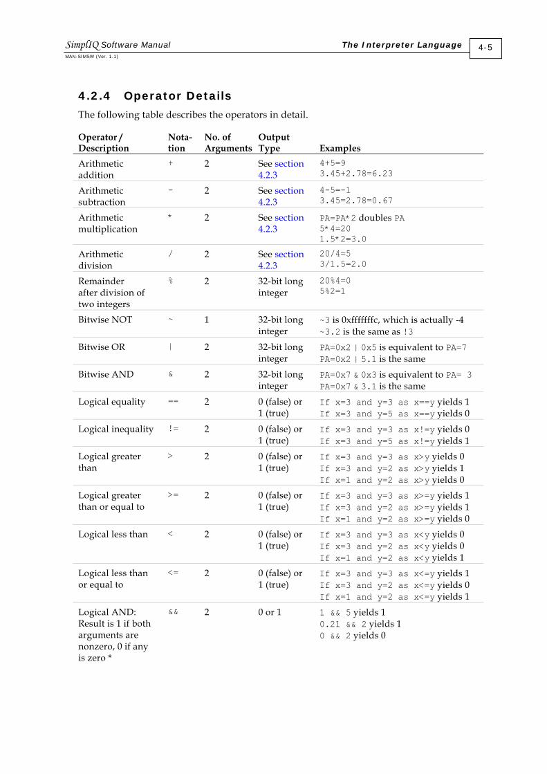
4.2.4 Operator Details
The following table describes the operators in detail.
Operator / Description
Nota- tion
No. of Arguments
Output Type
Examples
Arithmetic addition
+ 2 See section 4.2.3
4+5=9 3.45+2.78=6.23
Arithmetic subtraction
- 2 See section 4.2.3
4-5=-1 3.45=2.78=0.67
Arithmetic multiplication
* 2 See section 4.2.3
PA=PA*2 doubles PA 5*4=20 1.5*2=3.0
Arithmetic division
/ 2 See section 4.2.3
20/4=5 3/1.5=2.0
Remainder after division of two integers
% 2 32-bit long integer
20%4=0 5%2=1
Bitwise NOT ~ 1 32-bit long integer
~3 is 0xfffffffc, which is actually -4 ~3.2 is the same as !3
Bitwise OR | 2 32-bit long integer
PA=0x2 | 0x5 is equivalent to PA=7 PA=0x2 | 5.1 is the same
Bitwise AND & 2 32-bit long integer
PA=0x7 & 0x3 is equivalent to PA= 3 PA=0x7 & 3.1 is the same
Logical equality == 2 0 (false) or 1 (true)
If x=3 and y=3 as x==y yields 1 If x=3 and y=5 as x==y yields 0
Logical inequality != 2 0 (false) or 1 (true)
If x=3 and y=3 as x!=y yields 0 If x=3 and y=5 as x!=y yields 1
Logical greater than
> 2 0 (false) or 1 (true)
If x=3 and y=3 as x>y yields 0 If x=3 and y=2 as x>y yields 1 If x=1 and y=2 as x>y yields 0
Logical greater than or equal to
>= 2 0 (false) or 1 (true)
If x=3 and y=3 as x>=y yields 1 If x=3 and y=2 as x>=y yields 1 If x=1 and y=2 as x>=y yields 0
Logical less than < 2 0 (false) or 1 (true)
If x=3 and y=3 as x<y yields 0 If x=3 and y=2 as x<y yields 0 If x=1 and y=2 as x<y yields 1
Logical less than or equal to
<= 2 0 (false) or 1 (true)
If x=3 and y=3 as x<=y yields 1 If x=3 and y=2 as x<=y yields 0 If x=1 and y=2 as x<=y yields 1
Logical AND: Result is 1 if both arguments are nonzero, 0 if any is zero *
&& 2 0 or 1 1 && 5 yields 1 0.21 && 2 yields 1 0 && 2 yields 0
SimplIQ Software Manual The Interpreter Language MAN-SIMSW (Ver. 1.1)
4-5

Operator / Description
Nota- tion
No. of Arguments
Output Type
Examples
Logical OR: Result is 1 if any argument is nonzero, 0 if both are zero *
|| 2 0 or 1 1||0 yields 1 0||0 yields 0
Logical NOT: Result is 1 if argument is zero; otherwise it is 0*
! 1 0 or 1 !4 yields 0 !0 yields 1 !0.0004 yields 1
Unary minus: Result is negative if argument is positive, and vice versa*
- 1 Same as argument
-4.5 yields -4.5 -4 yields -4 (-4) yields 4 -5+5 yields 0
Bitwise left shift: Shifts 1st operand left by number of positions the 2nd operand specifies*
<< 2 32-bit long integer
8<<2 yields 32
Bitwise right shift: Shifts 1st operand right by number of positions the 2nd operand specifies*
>> 2 32-bit long integer
8>>2 yields 2
* The arguments are truncated to integers before evaluation.
Table 4-2: Operator Details
4.2.5 Mathematical Functions
The following table lists the built-in mathematical functions of the SimplIQ Interpreter language. Function names are case sensitive.
Operator Description Returns sin Sine Floating point cos Cosine Floating point abs Absolute value
Note: The absolute value of an input argument of hexadecimal 0x80,000,000 exceeds the long value range and will therefore be limited to the maximum long value for positive numbers.
Same type as input argument
sqrt Square root, or zero if argument is negative Floating point
SimplIQ Software Manual The Interpreter Language MAN-SIMSW (Ver. 1.1)
4-6

Operator Description Returns fix Truncate to integer:
fix(3.8) is 3 fix (-3.8) is -3 Note: If an input argument exceeds the long value range, it will be limited to the maximum long value (for positive numbers) or the minimum long value (for negative numbers).
Integer
rnd Truncate to nearest integer: rnd(3.8) is 4 rnd(-3.8) is -4 rnd(3.4) is 3 Note: If an input argument exceeds the long value range, it will be limited to the maximum long value (for positive numbers) or the minimum long value (for negative numbers).
Integer
sign Returns the sign of the input argument: -1 for negative numbers, 1 for positive numbers and zero for a zero. sign (-3.8) is -1 sign (3.8) is 1
Integer
real Convert integer to float. If argument is floating point number, the function does nothing: 5/2 is 2 real (5)/2 is 2.5 5/real (2) is 2.5
Floating point
Table 4-3: Mathematical Functions
4.2.6 Expressions
An expression is a combination of operands (parameters) and operators that is evaluated in a single value. Expressions work with immediate numbers, drive commands, and drive and global user-program variables. The following sections describe the different types of expressions.
4.2.6.1 Simple Expressions
A simple expression is evaluated in a single value. Any parameter and mathematical/ logical operator may be used to create a simple expression. Normally, simple expressions may be used as a part of other types of expressions.
Simple expressions are evaluated according to the operator priority, as specified in Table 4-1. In case of equal priorities, the expression is evaluated from left to right. The use of parentheses is allowed to 16 nesting levels.
SimplIQ Software Manual The Interpreter Language MAN-SIMSW (Ver. 1.1)
4-7

Examples:
Command Line Results Remarks SP*2/5+AC 101,000 The order is ((SP*2)/5) + AC IP|5 OR operation on IP 2+3 5 1,400,000 1,400,000
4.2.6.2 Assignment Expressions
Assignment expressions are used to assign a value to a variable or to a command. The syntax of an assignment expression is: <parameter or command name>=<simple expression>
Examples: SP=SP*2/5+AC OP=IP|5
If the variable or the command is a vector, the assignment is allowed only for its single member. The syntax of the vector member assignment is: <parameter or command name>[index]=<simple expression>
The index is an index of the relevant member vector. Indices are enumerated from zero.
Example: CA[1]=1
Be aware that when different types are assigned, the value may be truncated. If, for example, the variable or command type is integer and the assigned value is floating point, the floating value is rounded to the nearest integer. If a rounded integer value exceeds the integer range, this value is truncated to the nearest valid integer.
Example:
Expression Sent
Response Received
Remarks
AC=12,345.6789 – Assign floating value to integer AC command. AC 12,346 Floating value rounded to nearest integer. KV[10]=215.789e8 – Assign floating value to integer KV[10]
command. KV[10] 2,147,483,647 Floating value truncated to maximum integer
value.
When an integer value is assigned to a floating point command or variable, it is converted to a float. The conversion process may be imprecise due to the truncation into float IEEE format.
SimplIQ Software Manual The Interpreter Language MAN-SIMSW (Ver. 1.1)
4-8

Example: A floating point variable “tempt” is defined in a user program.
Expression Sent
Response Received
Remarks
TC=1 – Assign integer value to floating point command TC.
TC 1.0 Assigned integer value is converted to float. temp=12,345,678 – Assign integer value to floating point variable. temp 1.234568e+7 Assigned value is truncated to 12,345,680.0.
4.2.6.3 User Variables
User variables are defined within a user program. The description and syntax rules of the variable definition are outlined in Chapter 5:.
User program variables may be used within the command line only if a program was compiled successfully and downloaded to the drive. The user may then use the Interpreter to query a user variable value or change it.
The user should pay special attention to the scope of a variable. A variable may be defined at the global or local level. Local variables are available only within the function in which they are defined, while global variables are available within any function and outside a program.
A user variable may be queried or changed when the program is running or halted.
For example, suppose that a compiled program includes the following lines at the global level: int ZEBRA,GIRAFFE[3]; float GNU;
The expression GNU=ZEBRA*GIRAFFE[1]+2*sin(GIRAFFE[2]); is valid. User program variables are case sensitive.
4.2.6.4 Built-in Function Calls
The built-in function call may be used in a single expression. For a list of mathematical built-in functions, refer to Table 4-3. Non-mathematical built-in functions are as follows:
Operator Description Returns
tdif Time difference x=TM tdif(x) returns the time in msec since x=TM has been sampled.
Integer
emit(n) Emits the n TPDO (CAN transmit process data object), where n equals 1, 3 or 4. Details given in section 5.4.7.
Integer, 1 if function is completed successfully; otherwise 0
SimplIQ Software Manual The Interpreter Language MAN-SIMSW (Ver. 1.1)
4-9
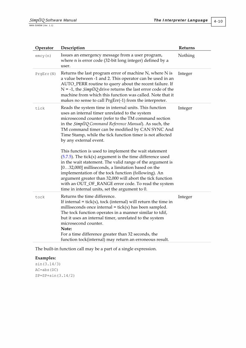
Operator Description Returns
emcy(n) Issues an emergency message from a user program, where n is error code (32-bit long integer) defined by a user.
Nothing
PrgErr(N) Returns the last program error of machine N, where N is a value between -1 and 2. This operator can be used in an AUTO_PERR routine to query about the recent failure. If N = -1, the SimplIQ drive returns the last error code of the machine from which this function was called. Note that it makes no sense to call PrgErr(-1) from the interpreter.
Integer
tick Reads the system time in internal units. This function uses an internal timer unrelated to the system microsecond counter (refer to the TM command section in the SimplIQ Command Reference Manual). As such, the TM command timer can be modified by CAN SYNC And Time Stamp, while the tick function timer is not affected by any external event. This function is used to implement the wait statement ( 5.7.5). The tick(x) argument is the time difference used in the wait statement. The valid range of the argument is [0…32,000] milliseconds, a limitation based on the implementation of the tock function (following). An argument greater than 32,000 will abort the tick function with an OUT_OF_RANGE error code. To read the system time in internal units, set the argument to 0.
Integer
tock Returns the time difference. If internal = tick(x), tock (internal) will return the time in milliseconds once internal = tick(x) has been sampled. The tock function operates in a manner similar to tdif, but it uses an internal timer, unrelated to the system microsecond counter. Note: For a time difference greater than 32 seconds, the function tock(internal) may return an erroneous result.
Integer
The built-in function call may be a part of a single expression.
Examples: sin(3.14/3) AC=abs(DC) SP=SP+sin(3.14/2)
SimplIQ Software Manual The Interpreter Language MAN-SIMSW (Ver. 1.1)
4-10
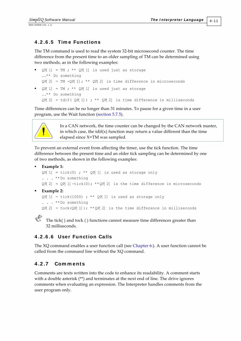
4.2.6.5 Time Functions
The TM command is used to read the system 32-bit microsecond counter. The time difference from the present time to an older sampling of TM can be determined using two methods, as in the following examples:
QP[1] = TM ; ** QP[1] is used just as storage ….** Do something QP[2] = TM -QP[1]; ** QP[2] is time difference in microseconds
QP[1] = TM ; ** QP[1] is used just as storage ….** Do something QP[2] = tdif( QP[1]) ; ** QP[2] is time difference in milliseconds
Time differences can be no longer than 31 minutes. To pause for a given time in a user program, use the Wait function (section 5.7.5).
In a CAN network, the time counter can be changed by the CAN network master, in which case, the tdif(x) function may return a value different than the time elapsed since X=TM was sampled.
To prevent an external event from affecting the timer, use the tick function. The time difference between the present time and an older tick sampling can be determined by one of two methods, as shown in the following examples:
Example 1: QP[1] = tick(0) ; ** QP[1] is used as storage only . . . **Do something QP[2] = QP[1]-tick(0); **QP[2] is the time difference in microseconds
Example 2: QP[1] = tick(1000) ; ** QP[1] is used as storage only . . . **Do something QP[2] = tock(QP[1]); **QP[2] is the time difference in milliseconds
The tick( ) and tock ( ) functions cannot measure time differences greater than 32 milliseconds.
4.2.6.6 User Function Calls
The XQ command enables a user function call (see Chapter 6:). A user function cannot be called from the command line without the XQ command.
4.2.7 Comments
Comments are texts written into the code to enhance its readability. A comment starts with a double asterisk (**) and terminates at the next end of line. The drive ignores comments when evaluating an expression. The Interpreter handles comments from the user program only.
SimplIQ Software Manual The Interpreter Language MAN-SIMSW (Ver. 1.1)
4-11

Chapter 5: The SimplIQ User Programming Language
SimplIQ servo drives read a user program in Elmo High-level language (EHL)1 after it has been translated by the compiler into a sequence of virtual assembly commands (described in Chapter 6:). The Compiler, part of the Elmo Studio IDE, is integrated into the Composer. The compilation process can run off line inside the PC. It is not part of the SimplIQ firmware. Before the SimplIQ drive executes a user program, the program must first be compiled, and the compiled code must then be downloaded to the serial flash memory of the SimplIQ drive. By compiling code prior to downloading, text analysis can be performed offline, saving online time and boosting user program performance. Another advantage is that user syntax improvements can be made without upgrading the drive software.
A drive program is a list of commands in a certain order. A user program can be anything from a simple list of commands to a very complicated machine management algorithm. The compiled code stored in the SimplIQ drive is a list of commands in a certain order.
This chapter descries how to write, maintain and run user programs for the SimplIQ drive.
5.1 User Program Organization
A user program is organized as follows:
Integer and floating point variable declarations
Program text, including expressions, commands, labels and comments
An exit directive, which may be used to terminate the program
Most Interpreter commands can be used in the program text. This feature is given for each command in the “Source” attribute of the command in the SimplIQ Command Reference Manual. Interpreter commands that cannot be used in a program are those that:
Upload or download data between the drive and its host. For example, VR cannot be used for version identification (upload process).
Store data in the flash memory or retrieve data from the flash memory For example, CD cannot be used to reload parameters from the flash memory. For example, XC## resumes a halted user program.
Are involved in executing the using program
1 The Elmo Clarinet, Mini-Saxophone and Saxophone digital drives use Elmo Low-level Language (ELL). The Elmo Studio (part of the Composer) can distinguish between these languages and activate the compilation process accordingly.
SimplIQ Software Manual The SimplIQ User Programming Language HARSF0703
5-1

In addition to the Interpreter commands, a program may include program flow statements that manage how the program runs:
Iterations, such as: for I=1:10:100
Subroutine execution commands, such as: If(I>=100)
Conditions, such as: while(I<1000)
In the program text, semicolons, commands, line feeds or carriage returns separate the commands, as in the following examples: int x,k; Variable declarations ##Func Label definition X=0; Initialize for K=0:10 Iterate X = x + 1 ; Do something End End of iteration Exit End of program directive ##Lab … More code
The program defines two variables named x and k. ##Func is an entry point. After compilation, this piece of code can be run by sending the command XQ##Func to the Interpreter.
When the program starts at ##Func, it clears the user variable x. This is not performed automatically and an initial value must be set manually for every relevant variable. The program then iterates 11 times, incrementing x with every iteration. Finally, x = 11.
The Exit command terminates program execution. Another code section can then be executed by sending the command XQ##Lab.
Example: switch (IP & 3) Select according to the two low input bits. case 1 The numerical interpretation of (IP&3) is 1. PR=1000; case 2 The numerical interpretation of (IP&3) is 2. PR=500; If value is two . . . otherwise PR=100; Otherwise . . . (last two bits are 0 or 3). end BG Begin motion.
This example moves an axis with a step that depends on the state of the digital inputs.
SimplIQ Software Manual The SimplIQ User Programming Language MAN-SIMSW (Ver. 1.1)
5-2
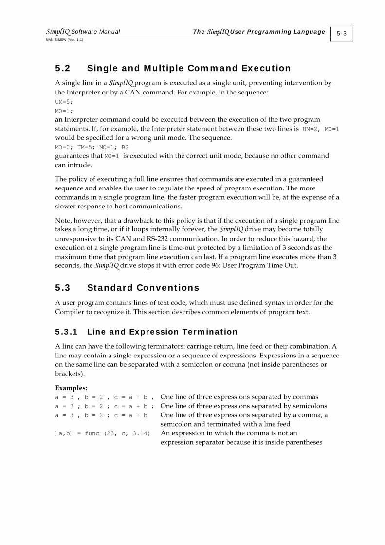
5.2 Single and Multiple Command Execution
A single line in a SimplIQ program is executed as a single unit, preventing intervention by the Interpreter or by a CAN command. For example, in the sequence: UM=5; MO=1; an Interpreter command could be executed between the execution of the two program statements. If, for example, the Interpreter statement between these two lines is UM=2, MO=1 would be specified for a wrong unit mode. The sequence: MO=0; UM=5; MO=1; BG guarantees that MO=1 is executed with the correct unit mode, because no other command can intrude.
The policy of executing a full line ensures that commands are executed in a guaranteed sequence and enables the user to regulate the speed of program execution. The more commands in a single program line, the faster program execution will be, at the expense of a slower response to host communications.
Note, however, that a drawback to this policy is that if the execution of a single program line takes a long time, or if it loops internally forever, the SimplIQ drive may become totally unresponsive to its CAN and RS-232 communication. In order to reduce this hazard, the execution of a single program line is time-out protected by a limitation of 3 seconds as the maximum time that program line execution can last. If a program line executes more than 3 seconds, the SimplIQ drive stops it with error code 96: User Program Time Out.
5.3 Standard Conventions
A user program contains lines of text code, which must use defined syntax in order for the Compiler to recognize it. This section describes common elements of program text.
5.3.1 Line and Expression Termination
A line can have the following terminators: carriage return, line feed or their combination. A line may contain a single expression or a sequence of expressions. Expressions in a sequence on the same line can be separated with a semicolon or comma (not inside parentheses or brackets).
Examples: a = 3 , b = 2 , c = a + b , One line of three expressions separated by commas a = 3 ; b = 2 ; c = a + b ; One line of three expressions separated by semicolons a = 3 , b = 2 ; c = a + b One line of three expressions separated by a comma, a semicolon and terminated with a line feed [a,b] = func (23, c, 3.14) An expression in which the comma is not an expression separator because it is inside parentheses
SimplIQ Software Manual The SimplIQ User Programming Language MAN-SIMSW (Ver. 1.1)
5-3

5.3.2 Line Continuation
A user program may contain a line that is too long, and whose representation on the screen is not easily readable because not all its symbols are shown on the screen. In order to improve program readability, the expression can be continued on the next line by using an ellipsis (three periods) to indicate that the line continues.
Example: c = 12 * a + sqrt(2) - sin(3.14 / 2) + 7 ^ 3 * … (6 + b) * 34 The ellipsis (…) at the end of the first line indicates that this expression is not complete and is continued on the next line.
5.3.3 Limitations
Every line of user program text may contain a maximum of 128 characters (for proper on-screen readability). If a text line exceeds this value, the Compiler issues an error.
Expressions also have limitations: the maximum admissible length of an expression is 512 symbols, not including comments and ellipses. If a program contains a complex expression that takes multiple lines, and the summary length of the expression (without comments and ellipses) exceeds 512 characters, the Compiler issues an error.
User program text is also limited according to the specific SimplIQ drive. The list of setup parameters that limit a user program are: Maximum length of user program text Maximum number of routines, including functions, labels and auto-routines Maximum number of variables, both global and local Maximum length of data segment — space for storing global variables Maximum length of code segment — space for compiled code
Maximum depth of stack — working space for the program.
The Elmo Studio IDE enables a user to view these parameters.
5.4 Expressions and Operators
5.4.1 Numbers
The number syntax in the user program language is similar to that of the Interpreter language (section 4.2.1), although ranges and range-exceeding behavior differ. A user program can be compiled on the PC in off-line mode (without communication), so that it has more resources than the Interpreter does.
The range for floating-point numbers is [-1e38…+1e38], which is greater than that of the Interpreter language. If an integer number exceeds the integer range, it is interpreted as a floating-point number, while the Interpreter interprets it as an error. If a floating-point number exceeds the floating-point range, it is interpreted as an error.
SimplIQ Software Manual The SimplIQ User Programming Language MAN-SIMSW (Ver. 1.1)
5-4
5.4.2 Mathematical and Logical Operators
The description and syntax is the same as for the Interpreter language (refer to section 4.2.2).
5.4.3 General Operator Rules
The description and syntax is the same as for the Interpreter language (refer to section 4.2.3).
5.4.4 Operator Details
The description and syntax is the same as for the Interpreter language (refer to section 4.2.4).
5.4.5 Mathematical Functions
The description and syntax is the same as for the Interpreter language (refer to section 4.2.5).
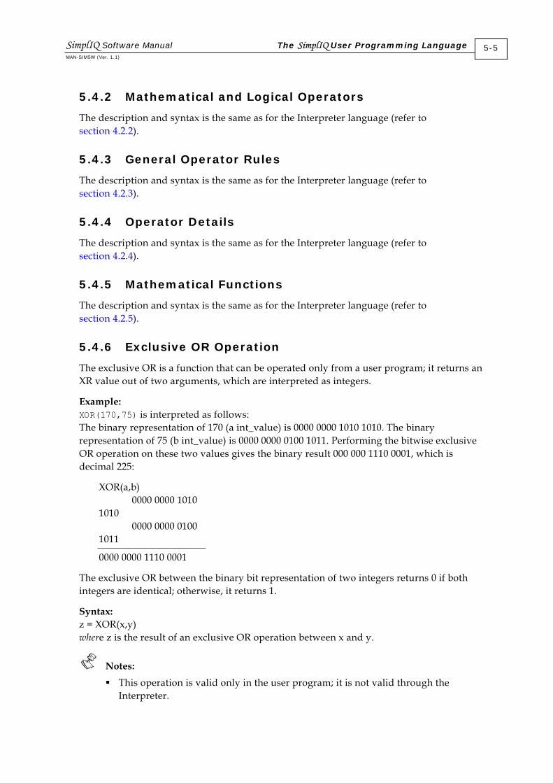
5.4.6 Exclusive OR Operation
The exclusive OR is a function that can be operated only from a user program; it returns an XR value out of two arguments, which are interpreted as integers.
Example: XOR(170,75) is interpreted as follows: The binary representation of 170 (a int_value) is 0000 0000 1010 1010. The binary representation of 75 (b int_value) is 0000 0000 0100 1011. Performing the bitwise exclusive OR operation on these two values gives the binary result 000 000 1110 0001, which is decimal 225:
XOR(a,b) 0000 0000 1010 1010 0000 0000 0100 1011
0000 0000 1110 0001
The exclusive OR between the binary bit representation of two integers returns 0 if both integers are identical; otherwise, it returns 1.
Syntax: z = XOR(x,y) where z is the result of an exclusive OR operation between x and y.
Notes: This operation is valid only in the user program; it is not valid through the
Interpreter.
SimplIQ Software Manual The SimplIQ User Programming Language MAN-SIMSW (Ver. 1.1)
5-5

If any floating-point type operand is converted to an integer.
5.4.7 CAN Object Emission
5.4.7.1 The Emit Function
The emit(n) function emits the n TPDO (Can Transmit Process Data Object) subject to the following restrictions:
The drive supports CAN communication.
The CAN communication state is operational.
n equals 1, 3 or 4.
The corresponding TPDO has its transmission type set to 254.
The corresponding TPDO is mapped to valid signals.
The emit(n) function returns 1 if successful and 0 if it does not succeed in emitting a TPDO. It returns immediately after the TPDO is placed in the CAN transmitter queue. The actual emission of the TPDO may be delayed.
5.4.7.2 The EMCY Function
The EMCY function issues an emergency message from a user program. It is valid only for drives that support CAN controllers.
Syntax: EMCY(x) where x is an error code (integer 4 bytes in length) defined by the user.
The EMCY() function always returns 0.
When the EMCY( ) function is called, the emergency message is transmitted only if bit 6 of object 0x2F20 (request by user program EMCY function) is set to 1. Refer to the object 0x2F20 section in the Elmo CANopen Implementation Manual.
When the program reaches a location at which an emergency is specified, the CAN emergency object (EMCY) is sent. The emergency object data is according to CiA DS301, with its 8 bytes of data as follows:
Byte Contents Remarks 0 1
Emergency error code 0xFF01 - device specific
2 Error register (object 0x1001) 0x80 - manufacturer specific 3 Used only for PT/PVT motion,
manufacturer error codes 0
4 5 6 7
Manufacturer-specific error field Error code defined by user as argument of EMCY function
SimplIQ Software Manual The SimplIQ User Programming Language MAN-SIMSW (Ver. 1.1)
5-6

Example: The following code sends an EMCY from a routine in two cases: timeout (error code 1) or out-of-range (error code 2): … if (isTimeOut) // Check if timeout occurred EMCY(1); // Issue EMCY with error code 1 end … if (isOutOfRange) // Check if out of range EMCY(2); // Issue EMCY with error code 2 end
If a timeout occurs, the SimplIQ drive sends an EMCY with the following data:
Byte Contents Remarks 0 01 1
Emergency error code FF
2 Error register - 0x80 (manufacturer specific) 80 3 Not used 0 4 01 5 0 6 0 7
Manufacturer-specific error field (1 for timeout)
0
If an out-of-range occurs, the SimplIQ drive sends an EMCY with the following data:
Byte Contents Remarks 0 01 1
Emergency error code FF
2 Error register - 0x80 (manufacturer specific) 80 3 Not used 0 4 02 5 0 6 0 7
Manufacturer-specific error field (2 for out-of-range)
0
Note that the user error code and the emergency error code are formatted in the messages starting with the least significant bit.
5.4.8 Expressions
An expression is a combination of operands (parameters) and operators that is evaluated as a single value. Expressions are used with immediate numbers, drive commands, and drive and global user-program variables. This section describes the different types of expressions.
SimplIQ Software Manual The SimplIQ User Programming Language MAN-SIMSW (Ver. 1.1)
5-7

5.4.8.1 Simple Expressions
The description and syntax of simple expressions is the same as for the Interpreter language (refer to section 4.2.6.1).
5.4.8.2 Constant Expressions
A constant expression is a simple expression that contains only operations with immediate numbers as operands. The Compiler recognizes the constant expression, evaluates it and uses the final result to generate the executable code of the SimplIQ drive. Note that the result of evaluating a constant expression by the Compiler may differ from the result calculated inside the SimplIQ drive, because the Compiler uses more resources and may evaluate and operate with double-precision floating-point numbers.
5.4.8.3 Assignment Expressions
The description and syntax is the same as for the Interpreter language (refer to section 4.2.6.2). User programming language allows multiple assignments to multiple outputs of the function.
5.4.8.4 User Variables
User variables are defined within the program, using the “int” or “float” declaration, with the following syntax: int int_var1, int_var2[12], …, int_varN; float flt_var1[13], flt_var2, flt_varN; int a; float b;
A variable must first be declared before it is used (in the expression or assignment). The variable definition line consists of type name (int or float) and variable names. Variables on the definition line must be separated by commas; alternatively, each variable may be declared on a separate line. Variables may be scalar (for example, int var1, float temp) or one-dimensional arrays (for example, int arr[10], float ftemp[4]). If a variable is a vector, it must be declared with its dimension in brackets after its name. The vector dimension must be a positive constant number. If the dimension is defined as a floating-point number, it will be truncated to an integer. A dimension of less than 1 is illegal.
Examples: int arr[12.5]; The floating-point number defining dimension will be truncated to 12. int arr[-2]; This variable definition is illegal because the dimension is negative.
Only global variables may be one-dimensional arrays. Neither a local variable nor an input/output argument of a function may be a vector.
Local variables must be defined at the beginning of function bodies. Any local or global variable definition after executable code of the function is illegal.
SimplIQ Software Manual The SimplIQ User Programming Language MAN-SIMSW (Ver. 1.1)
5-8

Example: function func (int a) Function definition int b ; Local variable definition b = a ; Executable code float c : Local variable definition return
The definition of the variable c is illegal because it comes after executable code.
The names of variables may include ASCII letters, digits (not leading) and underscores (not leading) only. Variable names are case sensitive. The maximum variable name length is 12 characters. A variable name cannot be a keyword.
The following is the list of keywords: int otherwise wait float break until if end goto else return nargin elseif function nargout for global XOR while exit quit switch virtual DummyLabel case reset try clear catch this leave cd pw save continue
All keywords are case sensitive.
Variable names must be distinct from function or label names.
After a program is compiled, all program variables may be used within the command line. For example, assume that a compiled program includes the following lines: int ZEBRA,GIRAFFE[3]; float GNU;
The expression GNU=ZEBRA*GIRAFFE[1]+2*sin(GIRAFFE[2]); is valid.
More information about global and local variables is given in section 5.8.5.
5.4.8.5 System Commands
The SimplIQ system commands (described fully in the SimplIQ Command Reference Manual) consist of a two-letter mnemonic notation (only English letters, not case sensitive). For example, the expressions ac = 100,000 and AC = 100,000 have the same meaning, although the notation is different.
Each command has a 16-bit flag, each bit defining any feature. For example, the fourth bit (PostProcess flag) defines whether the command can be used to set a value or not.
SimplIQ Software Manual The SimplIQ User Programming Language MAN-SIMSW (Ver. 1.1)
5-9

Examples:
a = AC This expression assigns a value of the system command AC to the variable a. It is valid if the AC command is allowed to “get a value”; that is, it has a PreProcess flag.
AC = a This expression assigns a value of the variable a to the system command AC. It is valid if the AC command is allowed to “set a value”; that is, it has a PostProcess flag.
BG This is an executable command. It cannot be assigned; that is, it has no PreProcess, PostProcess or Assign flag. For example, the expressions BG = 1 and a = BG are illegal.
LS This expression is illegal because it uses a command that has a NotProgram flag. Such commands are not allowed in a user program, although they are available for use in the Interpreter language.
5.4.8.6 Built-in Function Calls
The description and syntax is the same as for the Interpreter language (refer to section 4.2.6.4).
5.4.8.7 User Function Calls
Functions perform a pre-written and compiled code. They get a list of arguments from their caller and return a list of return values. Functions get their list of input arguments by value; they do not modify them directly. The general syntax of a function call is: [OUT1,OUT2,…OUTN]=FUNC(IN1,IN2,…IN_N)
If only one value is returned, brackets are not required and the syntax is as follows: OUT=FUNC(IN_1,…,IN_N)
Not all output variables must be assigned. For example, if the function FUNC returns two values, then [IA[1],IA[2]]=FUNC() assigns the two returned values to IA[1] and IA[2].
IA[1]=FUNC() returns the first return value to IA[1] and the other returned values remain unused. If the returned value type differs from the returned variable type, the result is a type cast to the type of the variable.
The number of input arguments during a function call is strictly according to its definition.
If a function call is part of an expression, then multiple output of the function is illegal. For example: [a, b] = 5 + func(c) and [a, b] = func(c) + 5 are both illegal because a function call is part of an expression and must be evaluated in a single value (refer to section 5.4.8.7).
SimplIQ Software Manual The SimplIQ User Programming Language MAN-SIMSW (Ver. 1.1)
5-10

5.5 Comments Comments are texts that are written into the code to enhance its readability. They can be written in three ways, as indicated in the following sections.
5.5.1 Double Asterisk A comment starts with a double asterisk (**) marker and terminates at the next end of line. The drive ignores the comments when running a program or evaluating an expression.
Example: **my first program PX=1 **UM=5 MO=1; **motor on
In this program, the first line is a comment used to enhance program readability. The comment terminates at the next end of line, so that the PX=1 instruction will be compiled and executed. In the third line, the comment marker tells the drive to ignore the UM=5 command. This technique is useful for temporarily masking program lines in the process of debugging. The last line demonstrates that a comment may start anywhere in the program line. The MO=1 instruction preceding the comment market will be compiled and executed.
5.5.2 Double Slash A double slash marks comments in the same way as a double asterisk. The comment starts with a double slash marker and terminates at the next end of line.
Example: //my first program PX=1 //UM=5 MO=1; //motor on In this example, the double slash acts exactly like the double asterisk from the previous example.
5.5.3 C-style Start and End Comment In the C-style method of marking comments, the comment begins with a start comment mark (/*) and terminates with the end comment mark (*/). This enables the user to close text in the middle of an expression, or to close several text lines.
Example: /* This is a multiple line comment. All this text is ignored. */ if ( 1 / x == 1 */) y=1; end The expression y = 1 will always be executed. The x==1 condition enclosed by the comment markers is ignored.
SimplIQ Software Manual The SimplIQ User Programming Language MAN-SIMSW (Ver. 1.1)
5-11

5.6 Fault Handling
5.6.1 Unexpected Fault
In order to receive more information about the reasons for run-time errors, the Elmo Studio IDE must be used. This enables the SimplIQ drive to inform the virtual assembly that a failure has occurred, and to then have the Elmo Studio interpret this to a user program command and error reason.
The AUTO_PERR routine enables the user to program failure reactions, which may include, for example, manipulating certain outputs, stopping the motor, or emitting a CAN emergency. The AUTO_PERR can determine locate the last error by using the PrgErr(N) function (described in section 5.4.8.6).
If, after taking emergency steps, the AUTO_PERR is to resume the user program, the following cautions should be taken:
A return command will resume execution at the next user program instruction. In most cases, after the unexpected failure of a previous instructions, this should be avoided.
Because the depth of the program stack is unknown at the time of failure, jumping to an absolute address should be carried out only after the reset command has reset the call stack.
The AUTO_PERR routine automatically blocks all other auto-routines; therefore, the MI command should be used to restore reaction to them.
The exit keyword can be used to exit the user program.
5.6.2 Expected Fault
Certain places in the user program are prone to faults; for example, a user program may fail to start a motor due to an externally-activated switch. To react to an unexpected fault, a try-catch block (section 5.7.11) should be used.
5.7 Program Flow Commands
The SimplIQ drive uses a set of commands to manage the flow of the user program. With these commands, the user program can make decisions iterate or respond automatically to certain events. The program flow commands enable user programs to perform much more complicated functions than just running a set of commands sequentially.
The program flow commands are:
while - end Iterate as long as condition is satisfied.
until Iterate (suspend program execution) until condition is satisfied.
wait Iterate (suspend program execution) until a specified time elapses.
for - end Iterate for a number of counted times.
break Break an iteration or a switch expression (for, while, switch)
SimplIQ Software Manual The SimplIQ User Programming Language MAN-SIMSW (Ver. 1.1)
5-12
if - elseif - else - end Conditional expression.
switch-case-otherwise-end Case selection.
goto Go to a certain point in the program.
reset Kill the state of the executing program and jump to a certain point in the program.
function-return Declare a function and its return point.
## Declare a label or an auto-routine.
#@ Declare a label or an auto-routine.
#@ - return Declare an auto-routine and its return point.
exit Terminate program execution.
continue Transfers control to next iteration of smallest enclosing for or while loop in which it appears.
try-catch Used to react to an expected fault.
5.7.1 Labels (Entry Points) and Subroutines
Labels denote that program execution can start from that location, or that program execution can be branched to that location.
Label definition has the following syntax: ##<LABEL_NAME> or #@<LABEL_NAME>
A maximum of 12 characters — letters and/or digits (not leading) and underscore (not leading) only — may be used for a label. The label name must be unique.
Labels can reside inside or outside function bodies, but not within a program flow structure, such as a for iteration. Labels inside function bodies are regarded as local to the function and serve as targets for goto instructions with the same function. Labels in the global text scope serve as possible execution starting points, and also as targets for reset and global scope goto.
A subroutine is a global label in which the body ends with a return keyword. A subroutine is similar to a function without input and output arguments. It can be called from any place in the program and may serve as a target for a reset instruction.
An auto-routine is a subroutine whose return keyword is an instruction to return to the next line in the code, from where the subroutine was called.
DummyLabel is a keyword used internally by the Compiler. It is not a legal label or subroutine name.
The XQ and the XC program launch commands use labels to specify where to start program execution and where to terminate. For example, the command XQ ##LOOP2 is used to begin execution at ##LOOP2.
SimplIQ Software Manual The SimplIQ User Programming Language MAN-SIMSW (Ver. 1.1)
5-13

Example 1: ##START; Start program. ##LOOP1; Label … Body code A Goto##LOOP1; ##LOOP2; … Body code B ##LOOP3; …
According to this example, if the program runs from label ##START, body code A will be performed forever. ##LOOP2 will never be reached.
Example 2: … #@WAIT_POWER: Subroutine definition wait 3000 subroutine body - wait 3 sec return End subroutine … WAIT_POWER Call subroutine … reset WAIT_POWER; Kill stack and call subroutine
In this example, the subroutine WAIT_POWER is called explicitly the first time and is used as the target for a reset instruction the second time.
5.7.2 For Iteration
This performs an indexed iteration in a program.
Syntax: for k=N1:N2:N3 … end Iterates k from N1 to N3 with a step of N2.
or
k=N1:N2 … end Iterates k from N1 to N2 with a step of 1.
In both cases, N1, N2 and N3 are numbers or simple expressions.
Notes: If the iteration step is zero, the program is aborted with the error code
INFINITE_LOOP.
If N1, N2 or N3 is a variable, it is evaluated once before the iteration begins. If the variable changes within the “for” loop, the iteration process is not affected.
SimplIQ Software Manual The SimplIQ User Programming Language MAN-SIMSW (Ver. 1.1)
5-14

The iteration variable k must be declared as a variable. The iteration variable must be scalar, not an array member. For example, the expression: for k[10]=1:10 is illegal because k is an array.
Example: … Start user program or function. float ra[20]; Float array declaration. int ia[20]; Integer array declaration. int k; Variable declaration. … for k=1:10 Start iteration loop. ia[k]=100; Update first 10 elements of integer array. ra[k]=55.55; Update first 10 elements of real array. … end End of iteration loop. …
5.7.3 While Iteration
Syntax: while(expression) … statement … end
The while keyword executes a statement repeatedly until expression becomes 0. The expression can be logical and/or numerical. It may be within parentheses or without parentheses.
Example: OB[1]=0 Digital output 1 is OFF. while(IB[1]) OB[1]=1 While digital input 1 is ON, digital output 1 is ON. end OB[1]=0; Digital output 1 is OFF. … … While (IB[2]) end MO=1; This command will be performed only after digital output 2 is OFF.
SimplIQ Software Manual The SimplIQ User Programming Language MAN-SIMSW (Ver. 1.1)
5-15

5.7.4 Until Iteration
Syntax: until (expression) ;
The until keyword suspends execution of the program until expression becomes true (nonzero). The expression can be logical and/or numerical.
Example: … until ((PX==20,000)&IB[1]); Suspend the program until the variable PX exceeds 20,000 and digital input 1 is ON. …
The until expression can be useful for synchronizing threads for drives that support multi-thread programs. For example, if there are two threads and the second thread must start after the first thread finishes a certain procedure, a global variable should be defined to indicate whether the first thread has finished or not. The second thread is suspended by the until expression, as follows:
int IsFirstFinished ; Global variable definition. Variable is initially set to zero.
The code of the first thread could be: … … Do some work… IsFirstFinished = 1 ; Signal that some work is complete.
The code of the second thread will include: … Prior to suspension code Until (IsFirstFinished) ; Second thread suspended until ** signal … Continue program.
To suspend the thread without terminating it, until can be used with a false expression.
5.7.5 Wait Iteration
Syntax: wait (expression) ;
The wait keyword suspends execution of the program until the specified time elapses. The expression can be within parentheses or without them. The expression specifies the waiting time in milliseconds. It can be a numerical expression only, and is evaluated in a single value.
Example: PA=10,000 BG until (MS == 0) wait (20) ; Wait 20 milliseconds
SimplIQ Software Manual The SimplIQ User Programming Language MAN-SIMSW (Ver. 1.1)
5-16
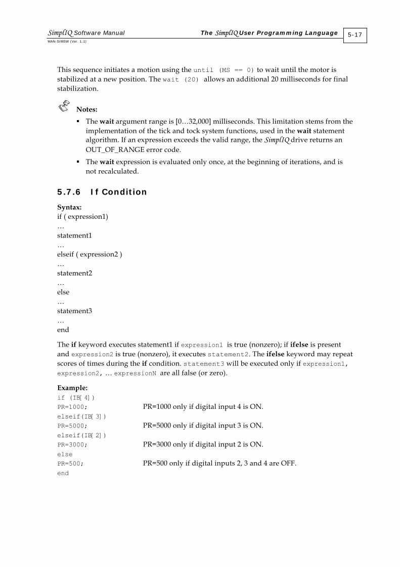
This sequence initiates a motion using the until (MS == 0) to wait until the motor is stabilized at a new position. The wait (20) allows an additional 20 milliseconds for final stabilization.
Notes: The wait argument range is [0…32,000] milliseconds. This limitation stems from the
implementation of the tick and tock system functions, used in the wait statement algorithm. If an expression exceeds the valid range, the SimplIQ drive returns an OUT_OF_RANGE error code.
The wait expression is evaluated only once, at the beginning of iterations, and is not recalculated.
5.7.6 If Condition
Syntax: if ( expression1) … statement1 … elseif ( expression2 ) … statement2 … else … statement3 … end
The if keyword executes statement1 if expression1 is true (nonzero); if ifelse is present and expression2 is true (nonzero), it executes statement2. The ifelse keyword may repeat scores of times during the if condition. statement3 will be executed only if expression1, expression2, … expressionN are all false (or zero).
Example: if (IB[4]) PR=1000; PR=1000 only if digital input 4 is ON. elseif(IB[3]) PR=5000; PR=5000 only if digital input 3 is ON. elseif(IB[2]) PR=3000; PR=3000 only if digital input 2 is ON. else PR=500; PR=500 only if digital inputs 2, 3 and 4 are OFF. end
SimplIQ Software Manual The SimplIQ User Programming Language MAN-SIMSW (Ver. 1.1)
5-17

5.7.7 Switch Selection
Syntax: switch (expression) case (case_expression1) … statement1 … case (case_expression2) … statement2 … otherwise … statement … end
The switch statement causes an unconditional jump to one of the statements that is the “switch body,” or to the last statement, depending on the value of the controlling expression, the values of the case labels and the presence or absence of an otherwise label.
The switch body is normally a compound statement (although this is not a syntactic requirement). Usually, some of the statements in the switch body are labeled with case labels or with the otherwise label. Labeled statements are not syntactic requirements either, but the switch statement is meaningless without them. The otherwise label can appear only once, and must appear after at least one case label. In contrast to the case label, the otherwise label cannot be followed by an expression for evaluation.
The switch and case expressions may be any logical and/or numerical expression. The case expression in the case label is compared for equality with the switch expression. If the switch expression and the case expression are equal, then this case is selected and the statements between the matching case expression and the next case or otherwise label are executed. After execution of the statements, a break keyword may appear. It is not necessary a case statement to finish with a break, because after executing the statements, an unconditional jump to the end of the switch is performed automatically, and the next case statement is not executed.
If a number of case expressions match the switch expression, then the first matching case is selected.
SimplIQ Software Manual The SimplIQ User Programming Language MAN-SIMSW (Ver. 1.1)
5-18

Example: The following example selects the size of a point-to-point motion according to the value of variable k. ink k Variable declaration … switch (k) For example, k=2 case 1 PA=1000; case2 PA=2000; This statement will be performed. otherwise PA=500; If k does not equal 1 or 2, PA=500. end
5.7.8 Continue
The continue keyword transfers control to the next iteration of the smallest enclosing for or while loop in which it appears. It thereby enables a jump from the current position to the beginning of the for and while loop, without executing statements through the end of the loop.
A continue keyword outside a for or while loop is illegal. The continue keyword may appear inside an if-else or a switch block. A continue keyword within a try-catch block is not allowed unless a for or while loop is completely enclosed within the try-catch block.
Example 1: . . . for k=1.5 if arr[k] == 0 continue end . . . end In this example, the continue keyword is within an if block. If the condition arr[k] == 0 is true, it jumps to the beginning of the for loop.
SimplIQ Software Manual The SimplIQ User Programming Language MAN-SIMSW (Ver. 1.1)
5-19

Example 2: while 1 . . . try . . . for k=0:5 if IB[16+k] == 1 break end if MS ! = 0 continue end MO=1;PA=0;BG end catch . . . end end If the condition MS ! = 0 is true, the program jumps to the beginning of the for loop and the statements MO=1;PA=0;BG are not executed.
5.7.9 Break
Syntax: break
The break statement terminates the execution of the nearest enclosing for, switch or while statement in which it appears. Control passes to the statement that follows the terminated statement. A break statement outside for, switch or while statements is illegal.
Example: … while (IB[2]) Loop until digital input 2 is ON. if (!IB[1] break; Break the loop when digital input 1 is OFF. end MO=1; This command will be performed only after digital input 1 or 2 is OFF.
5.7.10 Return
The return command terminates the current function and returns control to the invoking function. A called function normally transfers control to the function that invoked it when it reaches the end of the function. A return may be inserted within the called function to force an early termination and to transfer control to the invoking function. If the function was called by an execute (XQ) command, a return command will close that program thread. Closure of the main thread will close all other active threads.
SimplIQ Software Manual The SimplIQ User Programming Language MAN-SIMSW (Ver. 1.1)
5-20
Global variables can still be used and monitored by the user with external terminals, such as the Composer Smart Terminal.
5.7.11 Try-Catch
A try-catch block is used to react to an expected fault.
Syntax: try statement, …, statement, catch statement, …, statement end
The SimplIQ drive stores the status (stack and base pointers) and executes the statements between the try and the catch. If successful, nothing else happens. If an error occurs, the status is restored and the SimplIQ drive executes the catch block. A failure in the catch block is treated as an unexpected failure.
The SimplIQ drive cannot undo statements that were already executed in the try block before a failure.
Limitations for using a try-catch block include:
It is illegal to use goto and return statements within a try-catch block.
A control block within a try-catch block must be closed. For example: int a; … try if (a==1) catch … end … This example is illegal, because the if control block is not closed inside the try block.
A try-catch block within a control block must be closed. For example: int a; … if (a==1) try … else catch … end end … This example is illegal because the try-catch block is not closed within the if block.
SimplIQ Software Manual The SimplIQ User Programming Language MAN-SIMSW (Ver. 1.1)
5-21

5.8 Functions
Functions are program sections that can be defined by parameters and called from anywhere in the program.
5.8.1 Function Declaration
A function declaration consists of the following parts:
Reserved function keyword
List of output arguments with their types in brackets (optional)
Assignment sign, only if there is an output argument
Function name
List of input arguments with their types in parentheses (list of input arguments can be empty)
Reserved return keyword that closed the function scope
Example 1: function [int y1, int y2] = func1 (float x1, int x2) A function named func1 has two input arguments — x1 and x2 — and returns two output arguments.
The list of output arguments may be empty. In this case, two and three items are absent, or the brackets can be empty. If there is only an output argument, it can be without brackets. The maximum admissible number of input and output arguments is 16.
Example 2: function func2 (float x1) A function named func2 has a single input argument of float type and returns no output.
Example 3: [int y1] = func3 (int x1) This function declaration is illegal because the function keyword is missing.
Example 4: function y1 = func5 This function prototype is illegal because the type of output variable is missing
The valid function name follows the same rules as the variable name. It must be distinct from any variable, function or label name. The definition of dimensions of the output and input arguments at the function declaration is illegal.
Example 5: function [int x[100]] = func3 () This function declaration is illegal because the dimension of the output argument is defined
A function may have a prototype before its declaration. The prototype has the same syntax as the function declaration, but it must end with a semicolon.
SimplIQ Software Manual The SimplIQ User Programming Language MAN-SIMSW (Ver. 1.1)
5-22

Example 6: function [float y1] = func4 () ; A prototype of function func4 that has no input argument and returns only the output argument.
Example 7: function float y1 = func4 ; Same as example 6.
Example 8: function float = func4 ; Same as examples 6 and 7. The name of input or output argument of the function prototype may be omitted, but during function definition, it will be an error.
Example 9: function [int, int] = func1 (float, int); Prototype of function from example 1. Same as function [int y1, int y2] = func1 (float x1, int x2) ;
The prototype of the same function can be written several times (multiple prototype), but all prototypes must be identical. The names of the input/output arguments in the function prototype may be omitted, or may be different from the names of the corresponding argument names in the function declaration.
Example 10: function [int y1, int y2] = func (float x1, int x2) ; function [float y1, int y2] = func (float x1, int x2) The first expression is the function prototype and the second is the function definition. This is illegal because the type of first output argument in the prototype does not match that of the declaration.
Example 11: function [int y1, int y2] = func (float x1, int x2) ; function [int a, int b] = func (float x1, int x2) ; function [int y1, int y2 ] = func (float x1, int x2) The first two expressions are the function prototype and the third is the function definition, which is legal.
The body of a function resides below the declaration and must end with the return keyword. If the return is inside a control block within the function body, it is not the end of the function body.
Example 12: function [int y1, int y2] = func (float x1, int x2) Function definition. y1 = x1; Function body y2 = x2; if x2 > 0 If block Return return inside block is not
end of the function end End of if block
SimplIQ Software Manual The SimplIQ User Programming Language MAN-SIMSW (Ver. 1.1)
5-23

y2 = y1 + y2 ; Executable code Return Function end
Before a function call, the function must be declared, either as a function prototype or a function definition.
Example 13: function [int y1, int y2] = func (float x1, int x2;) Function prototype … function main () Function main definition int a, b; Local variable definition [a,b] = func (2.3, -9.0); Function call Return Function main end … function [int y1, int y2] = func (float x1, int x2) Function definition … Function body Return Function end
If a function is declared without a body, its call is illegal.
Example 14: function [int y1, int y2] = func (float x1, int x2) ; Function prototype … function main () Function main definition int a, b; Local variable definition [a,b] = func (2.3, -9.0); Function call Return Function main end …
In this example, function func has a prototype, but no body, so its call is illegal.
5.8.2 Dummy Variables
The input and output arguments of a function are called dummy variables. A true variable is substituted for the dummy variable when a function is called.
Example: function [float mean, float std]=statistic();
In this function, variables mean and std are dummy variables (full example in section 5.8.3).
5.8.3 Count of Output Variables
A function may return multiple values, although in certain cases, not all outputs need be computed. The nargout keyword can therefore be used to indicate which of the results actually need to be evaluated.
The number of outputs is the number of items in the left side of the expression during the function call. If this number exceeds the maximum number of defined output arguments for the function, or the maximum admissible number of output arguments, an error will be declared.
SimplIQ Software Manual The SimplIQ User Programming Language MAN-SIMSW (Ver. 1.1)
5-24

If a function does not return any output by definition, a zero output value will be inserted to the stack. For example, if the function func is declared with no output arguments, the expression func( ) + 3 is legal because func returns zero by default.
Example: float vec[11], RA[100]; Declare the global variables.
float value; Declare the global variable.
function [float mean, float std]=statistic(); Function prototype.
…
[RS[1],RA[2]]=statistic() Call the statistic function. After execution, RA[1] will be equal to variable mean and RA[2] will be equal to variable std.
[value]=statistic() In this case, after executing the statistic function, value will be equal to variable mean.
…
function [float mean, float std]=statistic(); Declare a function that calculates mean and standard deviation of the global vector vec.
int k; Declare k as automatic variable.
global vec[11]; Redeclare for vec variable (vec is global variable previously declared).
mean=0;
for k = 1:10
mean = mean + vec[k];
End
mean = mean/10; Calculate mean of vec[ ]
if (nargout>1) Only if standard deviation is queried . . .
std = 0;
for k = 1:10
std = std + vec[k] * vec [k];
End
st = (1/10) * ssrt. (std – 10 * mean)
End
Return End of function body
…
For count of input arguments, the number of input arguments during a function call must be the same as declared during the function definition.
SimplIQ Software Manual The SimplIQ User Programming Language MAN-SIMSW (Ver. 1.1)
5-25

5.8.4 Automatic Variables
A variable declared within a function is automatic; it is generated when the function is called and ceases to exist when the function exits. At the time of the function call, all of its automatic variables are set to zero. When the function exits, the value of the automatic variables is not saved.
Automatic variables cannot be vectors.
Example: In the example of the statistic function in section 5.8.3, variable k is the automatic variable.
5.8.5 Global Variables
A function can reference a persistent variable, which, in this case, must be declared as global inside the function and defined above the function definition. The global keyword is obligatory; otherwise, the variable will be referenced as an automatic variable of the function.
The dimension of a persistent variable is defined once in a program, during its definition, and is the same for the global variable in all functions in which it is used. The legal way to declare the dimension of a persistent variable within a function is to use empty brackets after its name, or no brackets at all.
Examples:
In the example of the statistic function in section 5.8.3, variable vec[11] is the global variable. It is defined above the function definition and is redeclared as global within the function body. float temp; Declare the global vector variable. int vec[10]; Declare the global vector variable. … function [float a]=func(int b) Declare a function func. float temp; Declare temp as an automatic variable,
because the global keyword is absent. … Function body. return End of function. … function [float a]=func1(float temp) Declare function func1. In this case, temp is
not a global variable, but rather an input argument.
… return End of function. … function [float a]=func2(float b) Declare function func2. global float temp; Redeclare global variable temp. In this
function, temp is the global variable.
SimplIQ Software Manual The SimplIQ User Programming Language MAN-SIMSW (Ver. 1.1)
5-26

global int vec[] Redeclare global variable vec. Notice that its dimension is omitted during redeclaration and that its actual dimension is 10, as defined above.
5.8.6 Jumps
Syntax: goto ##LABEL1
The goto command instructs the program to continue its execution at the label specified by the jump command. It may be specified only for destinations within the present function scope and is illegal if used in a for loop or switch-case block. Jumps to labels within other functions are not possible. Jumps to a global label from within a function are illegal.
Example: … Working code. if (PX>1000) Condition for jump. goto##LABEL1; Go to LABEL1 if condition is true. else Return axis to origin. goto##LABEL2; Go to LABEL2 if condition is false. end
… Working code. ##LABEL1; Declare LABEL1. … Working code. ##LABEL2; Declare LABEL2. … Working code.
5.8.7 Functions and the Call Stack
A function is a piece of code that may be called from anywhere in the program. After the function is executed, the program resumes from the line just after the function call.
Example:
function JustSo; Function prototype.
…
JV=1000
JustSo() Function call.
BG
…
function JustSo Function definition
IA[1]=1; Function body.
return Function end.
SimplIQ Software Manual The SimplIQ User Programming Language MAN-SIMSW (Ver. 1.1)
5-27

This code executes the sequence: JV=1000;IA[1]=1;BG;
After executing JV=1000, the program jumps to the subroutine JustSo. Before doing so, it stores its return address, which is the place in the code at which execution should resume after the routine is complete. In this example, the return address is the line number of instruction BG, which is just after the subroutine call.
The return command instructs the program to resume from the stored return address. After execution is resumed at that address, it is no longer required and is no longer stored.
Functions may call each other; in fact they may even call themselves. Return addresses for nested function calls are stored in a call stack, as shown in the following example: function factorial(); Function prototype. … IA[1]=3 IA[2]=1 factorial() Function call. BG … function factorial() Function for factorial. global int IA[]; Define array as global inside function. IA[2]=IA[2]*IA[1] Recursive algorithm. IA[1]=IA[1]-1 if (IA[1]>1) factorial() ; end Recursive call. return Function end
The factorial function in this example calculates the factorial of 3 in IA[2]. The variable IA[1] counts how many times the function factorial is executed.
The program executes as follows:
Code IA[1] IA[2] Call Stack IA[1]=3 3 Undefined Empty IA[2]=1 Unchanged 1 Empty factorial Unchanged Unchanged →BG IA[2]=IA[2]*IA[1] Unchanged 3 Unchanged IA[1]=IA[1]-1 2 Unchanged Unchanged if (IA[1]>1) factorial(); end
Unchanged Unchanged →RT →BG
IA[2]=IA[2]*IA[1] Unchanged 6 Unchanged IA[1]=IA[1]-1 1 Unchanged Unchanged if (IA[1]>1) factorial(); end
Unchanged Unchanged Unchanged (condition is false)
return Unchanged Unchanged →BG (program jumps to return on top of call stack)
return Unchanged Unchanged Empty (program jumps to BG on top of call stack)
BG Unchanged Unchanged Unchanged
SimplIQ Software Manual The SimplIQ User Programming Language MAN-SIMSW (Ver. 1.1)
5-28

5.8.8 Killing the Call Stack
In rare situations, it may be desirable to exit a function without returning to its return address. The reset instruction solves this problem by emptying the call stack before making a jump.
Syntax: reset<JUMP_NAME>
The valid jump after the reset keyword is one of the following:
Label
Auto-routine
User function with no defined input arguments
All other expressions or absence of expressions after the reset keyword are illegal.
A label in a reset expression must be global. A local label is illegal, because the stack will be emptied and all local variables and the return address of the function to which the local label belongs will be erased.
Example: Assume that a drive (an axis) runs a programmed routine. An inspection station may assert a “Product defective” digital signal that is coupled with digital input #1. An automatic routine is therefore coupled to digital input #1 in order to stop the part assembly and prepare for the assembly of the next part.
##START_NEW Label for starting a new part.
… Working code.
… Last line of working code.
#@AUTO_I1 Subroutine label.
PA=0;BG Return axis to origin.
reset START_NEW Clear stack and go to beginning.
The reset in the #@AUTO_I1 routine is required because it is not known if any function calls are executing when digital input #1 is asserted. If a function is executing, the reset prevents junk from accumulating in the call stack. Otherwise, the call stack is empty and reset does no harm. Note that after the reset, control does not return to the function that was executing prior to the #@AUTO_I1 routine. The stack is cleared and the return address to the interrupted function is removed from the stack.
The #@ATUO_I1 routine is executed after the work code is completed for every assembled part. The program proceeds form the last line of the working code to PA=0;BG, which resets the machine for another part assembly. The next instruction is a reset to the START_NEW label.
SimplIQ Software Manual The SimplIQ User Programming Language MAN-SIMSW (Ver. 1.1)
5-29

5.8.9 Automatic Subroutines
5.8.9.1 List of Automatic Routines
An automatic routine (auto-routine) is a special type of routine that is executed automatically according to system events. These routines are executed only when their invocation condition is satisfied. Auto-routines have no output and input arguments.
Syntax: An auto-routine can defined either as a function or as a subroutine:
If defined as a function, all syntax rules for function definition are relevant (see section 5.7.1).
If defined as a subroutine, the auto-routine name follows the sequence of characters ## or #@ in the definition line. The body of the auto-routine follows the definition line and ends with the return keyword unless this return is inside a flow control block (see section 5.7.1).
After calling the auto-routine and performing its body, the return keyword instructs the program to return to the line in the code after which execution was halted by a interrupt event.
There are no default handlers for auto-routines. If a user does not define the auto-routine, no handling will be activated when an automatic event is asserted.
The following table summarizes all automatic routines, ordered from highest to lowest priority.
Routine Name Priority Activated by Mask (MI) AUTOEXEC 0 An autoexec code is executed automatically
upon power on. An autoexec function can be called subsequently at any time.
1 (0x1)
AUTO_PERR 1 Called when a run-time error occurs (see section 5.6.1).
32,768 (0x8000)
AUTO_ER 2 A motor fault event, in which MO=0 is set automatically.
2 (0x2)
AUTO_STOP 3 Called when a digital input configured to the “Hard Stop” function is activated.*
4 (0x4)
AUTO_BG 4 Called when a digital input configured to the “Begin” function is activated.*
8 (0x8)
AUTO_RLS 5 Called when a digital input configured to the “RSL” function is activated.*
16 (0x10)
AUTO_FLS 6 Called when a digital input configured to the “FLS” function is activated.*
32 (0x20)
AUTO_ENA 7 Called when a digital input configured to the “Enable” function is activated.*
64 (0x40)
AUTO_I1 8 Called when a digital input #1 configured to the “GPI” (General Purpose Input) function is activated.*
128 (0x80)
SimplIQ Software Manual The SimplIQ User Programming Language MAN-SIMSW (Ver. 1.1)
5-30

Routine Name Priority Activated by Mask (MI) AUTO_I2 9 Called when a digital input #2 configured to
the “GPI” (General Purpose Input) function is activated.*
256 (0x100)
AUTO_I3 10 Called when a digital input #3 configured to the “GPI” (General Purpose Input) function is activated.*
512 (0x200)
AUTO_I4 11 Called when a digital input #4 configured to the “GPI” (General Purpose Input) function is activated.*
1024 (0x400)
AUTO_I5 12 Called when a digital input #5 configured to the “GPI” (General Purpose Input) function is activated.*
2048 (0x800)
AUTO_I6 13 Called when a digital input #6 configured to the “GPI” (General Purpose Input) function is activated.*
4096 (0x1000)
AUTO_HM 14 Called when a main homing sequence is completed.**
8192 (0x2000)
AUTO_HY 15 Called when an auxiliary homing sequence is completed. ***
16,384 (0x4000)
* Refer to the IL command section in the SimplIQ Command Reference Manual. ** Refer to the HM command section in the SimplIQ Command Reference Manual. *** Refer to the HY command section in the SimplIQ Command Reference Manual.
Table 5-1: Automatic Subroutines and Their Priorities
All automatic routines except AUTOEXEC are activated only if a program is running.
Example:
##LOOP An endless loop.
goto##LOOP
#@AUTO_I3 Subroutine definition.
… Subroutine body.
return End of subroutine.
In this program, the endless loop in the first two lines of the routine is intended to make the program run forever, so that the automatic routine will be able to handle the digital input #3 event.
The #@AUTO_I3 routine will be called if digital input #3 is sensed and not masked. Digital input #4 will not invoke any automatic action in the user program, because no #@AUTO_I4 routine is defined to handle a digital input #4 event. The user has the option to make an explicit call of an automatic routine, if desired. The syntax for an auto-routine call is the same as that of a user function.
SimplIQ Software Manual The SimplIQ User Programming Language MAN-SIMSW (Ver. 1.1)
5-31

5.8.9.2 Automatic Routine Arbitration
Each automatic routine has an assigned priority, according to Table 5-1. When the conditions for activating two automatic subroutines occur simultaneously, the automatic subroutine with the higher priority is called. The other automatic subroutine will be marked as pending and will execute at the first opportunity in which it receives permission to execute, even if the reason for its call does not exist any more.
5.8.9.3 The Automatic Subroutine Mask
Automatic subroutines can be masked, to indicate that they are inactive. For example, it may be desirable to limit the automatic response to a certain digital input to certain situations. This is carried out using the MI command.
Example: A drive receives a PLC command. It has an autoexec routine that activates its program upon boot. The PLC sends instructions to the drive using RS-232 communication for task parameters and a digital input to start an action immediately. The drive sets the output according to the state of the program. For safety sake, the drive is not allowed to perform any task before digital input 2 is set. function autoexec () Declare the autoexec function. MI=128; Inhibit the routine #@AUTO_I1. OP=1; Set output to indicate start. … while (!IB[2]) Wait for digital input 2 to be set. End goto #@TEST_PARS; Jump to subroutine. ##LOOP Label LOOP. … Label LOOP body. goto **LOOP; Endless loop. #@TEST_PARS Subroutine. OP=2; Set output 2. wait 2000; Wait 2 seconds for testing the part. MI=0; Enable automatic handling of digital input #1. goto ##LOOP; return End of automatic function. #@AUTO_I1 Automatic handler for digital input #1. OP=3; Set output 3 to indicate that digital input #1
is sensed. … Subroutine body. return Subroutine end. … exit Exit program.
SimplIQ Software Manual The SimplIQ User Programming Language MAN-SIMSW (Ver. 1.1)
5-32

The mask may also be used to prevent switch bouncing from generating spurious routine calls.
Example: A machine performs a periodic task. Digital input #1 is connected to a sensor to which the drive should react. The following code limits the automatic response to digital input #1 during execution of the #@AUTO_I1 routine code, even though digital input #1 may bounce. ##LOOP; Repetitive task. …
MI=0; Re-enable automatic routine. …
goto##LOOP;
#@AUTO_I1 Automatic handler for digital input #1. MI=MI|128; Prevent nested calls to #@AUTO_I1. … Subroutine body. return Subroutine end.
SimplIQ Software Manual The SimplIQ User Programming Language MAN-SIMSW (Ver. 1.1)
5-33

Chapter 6: Program Development and Execution
The process of SimplIQ drive program development includes the following steps:
Program editing: Write and/or edit the program.
Compilation: Use the Compiler to process the program and find errors.
Program loading: Load the program to the +flash memory of the drive.
Debugging: Observe the behavior of the program and correct it where necessary.
Running the program
Saving to flash: Move the program permanently to the drive.
The Elmo Studio IDE includes all the tools needed to perform this procedure. Using the Elmo Studio is fully explained in Chapter 4 of the Composer for SimplIQ Software Manual.
6.1 Editing a Program
The drive program is written in simple text, using any text editor. The Elmo Studio is recommended for program editing because it provides several additional services such as downloading a program to the drive, compiling the program and running it.
6.2 Compilation
Each user program must be compiled after editing. Although the Compiler does not reside in the DSP software, it is described here because it is an integral part of the program development process. The Compiler in the Elmo Studio is external, stand-alone software that can be accessed through the Composer software. The user can write and compile a program in off-line mode (without establishing communication with the drive) and then use the Compiler to compile the program in order to produce address maps and run-time code. If, in the course of compilation, the Compiler finds syntax errors, it stops the compilation process and informs the user about the errors, presenting them in convenient form.
The Compiler is composed of a preprocessor and a code generator. The preprocessor evaluates pragmas and constant expressions and is described in section 6.3.
The Compiler accepts the user program as a text file and files with target SimplIQ drive information. This information is required in order to ensure that the compiled code can run on the SimplIQ drive.
While the Compiler can locate syntax errors, it cannot find:
Out-of-range command arguments
Bad command contexts, such as an attempt to begin a motion when the motor is off. These errors must be corrected in the debugging stage.
SimplIQ Software Manual Program Development and Execution MAN-SIMSW (Ver. 1.1)
6-1
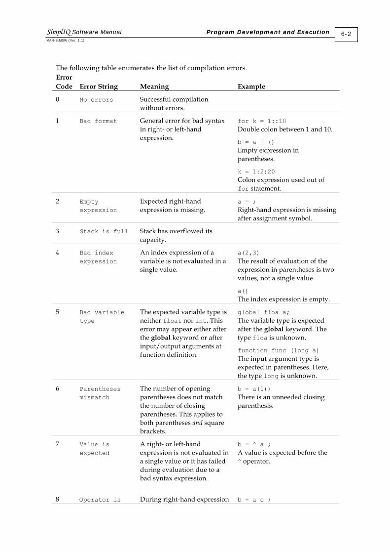
The following table enumerates the list of compilation errors. Error Code
Error String
Meaning
Example
0 No errors Successful compilation without errors.
1 Bad format General error for bad syntax in right- or left-hand expression.
for k = 1::10 Double colon between 1 and 10.
b = a + () Empty expression in parentheses.
k = 1:2:20 Colon expression used out of for statement.
2 Empty expression
Expected right-hand expression is missing.
a = ; Right-hand expression is missing after assignment symbol.
3 Stack is full Stack has overflowed its capacity.
4 Bad index expression
An index expression of a variable is not evaluated in a single value.
a(2,3) The result of evaluation of the expression in parentheses is two values, not a single value.
a() The index expression is empty.
5 Bad variable type
The expected variable type is neither float nor int. This error may appear either after the global keyword or after input/output arguments at function definition.
global floa a; The variable type is expected after the global keyword. The type floa is unknown.
function func (long a) The input argument type is expected in parentheses. Here, the type long is unknown.
6 Parentheses mismatch
The number of opening parentheses does not match the number of closing parentheses. This applies to both parentheses and square brackets.
b = a(1)) There is an unneeded closing parenthesis.
7 Value is expected
A right- or left-hand expression is not evaluated in a single value or it has failed during evaluation due to a bad syntax expression.
b = ^ a ; A value is expected before the ^ operator.
8 Operator is During right-hand expression b = a c ;
SimplIQ Software Manual Program Development and Execution MAN-SIMSW (Ver. 1.1)
6-2

Error Code
Error String
Meaning
Example
expected evaluation, there is no operator or terminator of a simple expression after successful value evaluation.
After successful evaluation of a, an operator or expression terminator is expected, but c is not recognized as either an operator or terminator.
9 Out of memory in the data segment
During memory allocation for a global variable, there is not enough space in the data segment.
10 Bad colon expression
Error during evaluation of a colon expression. The colon expression may appear only in a for statement. Bad syntax — more than three values or less than two values — in the colon expression may also cause this error.
for k = 10:-1:5:9 Colon expression contains more than three values.
for k = a Expected colon expression is missing in the for statement, after the =.
11 Name is too long
Variable or function name exceeds 12 characters.
int iuyuafdsf_876234 ;
12 No such variable
Left-hand value is not recognized as either a variable or as a system command.
de = sin(0.5) de is neither a variable nor a function.
13 Too many dimensions
Dimension of array exceeds the maximum admissible number of dimensions (syntax allows only one dimensional array).
int arr[12][2]; An attempt is made to define a two-dimensional array.
14 Bad number of input arguments
The number of input arguments during a function call does not match the number of input arguments at the function definition.
function func(float a); … func(a,2); The number of input arguments during the function call is two, while the function func is defined with only the input argument.
15 Bad number of output arguments
Bad syntax in left-hand expression: multiple output without brackets, or multiple output that exceeds maximum admissible number of outputs (maximum of 16 outputs is allowed).
a, b = func(1,2); Multiple outputs must be within brackets.
16 Out of memory Compilation process ran out of memory. This error may
SimplIQ Software Manual Program Development and Execution MAN-SIMSW (Ver. 1.1)
6-3

Error Code
Error String
Meaning
Example
occur if the user program is too large or too complex and there is not enough space in the code segment or in the Symbol table.
17 Too many arguments
The number of input or output arguments exceeds the maximum admissible number of input or output arguments (16).
function func (int a1, int a2, int a3, int a4, int a5, int a6, int a7, int a8, int a9, int a10, int a11, int a12, int a13, int a14, int a15, int a16, int a17, int a18, int a19, The number of input arguments exceeds 16.
18 Bad context The Compiler has found an error in the program context, such as mismatched brackets/ parentheses or an improperly closed flow control statement.
19 Write file error
An error occurred while writing to a file.
20 Read file error
An error occurred while reading from a file.
21 Internal compiler error: bad database
A corrupted database has caused an internal compiler error. In this case, email technical support at [email protected]. Attach the Composer date and version (in the Help menu) and the program that you attempted to compile.
22 Function definition is inside another function or flow control block
An illegal function definition. if a<0 a = 0; function func (int a);end Attempt to define a function inside if block.
23 Too many functions
The user program contains too many functions and there is not enough space for them in the database.
24 Name is keyword
A variable or function has the same name as a keyword. This error may occur if a variable name is identical to
int switch;
switch is a keyword, so its use as a variable name is illegal.
SimplIQ Software Manual Program Development and Execution MAN-SIMSW (Ver. 1.1)
6-4

Error Code
Error String
Meaning
Example
variable name is identical to an auto-routine name.
25 Name is not distinct
A variable of function name is not unique.
int func ; function func (int a) The function and the variable have the same name.
function func (int a) int a ; The definition of local variable a is illegal because this function already contains a local variable a as an input argument.
26 Variable name is invalid
This error occurs when:
A variable or function name starts with a digit or underscore, not with a letter
A variable or function name is empty.
On the variable definition line, a comma is used as a separator between variables, but the variable name after a comma is missing.
int_abc ; The variable name has a leading underscore.
function (int a) The function name is missing after the function keyword.
int a, b, The variable name is missing after the comma.
27 Bad separator between variables
The only legal separator between variables on the variable definition line is a comma. After a variable name, either a variable separator (comma) or an expression terminator is expected. Any other symbol causes this error.
int a b; A command as a variable separator is missing between a and b.
28 Illegal global variable definition
A global variable must be declared inside a function with the global keyword and it must be defined before the function. This error appears only if the global keyword is used in the wrong context:
The global keyword was used outside the function.
int a1 ; function func (int a) global float a1; The variable type a1 at its definition is int, while inside the function, it is declared as float.
SimplIQ Software Manual Program Development and Execution MAN-SIMSW (Ver. 1.1)
6-5

Error Code
Error String
Meaning
Example
A variable declared as global inside a function is not defined previously.
The type of variable declared at definition outside the function differs from the type of the declaration inside the function.
29 Bad variable definition
All local variables must be defined at the beginning of the function. Any variable definition coming after executable code in the function is illegal.
function func (int a) int b; global int a1; b = a; float c, d; The definition of float variables c and d is illegal because it occurs after executable code b = a.
30 Variable is undefined
Iteration variable in a for statement is not defined before it.
function func (int a) for k = 1:10 a = k: end return The iteration variable k is not defined before its use.
31 Bad separator between dimensions
Bad separator between dimensions (not a comma). This error is unused, because currently only one-dimensional arrays are allowed, so there is no need for a separate between dimensions.
32 Bad variable dimension
The legal variable dimension must be a positive number inside brackets. An expression inside brackets that is not evaluated into a number, or a number that is less than 1 (zero or negative) is illegal.
int arr[12]; Variable dimension is negative
33 Bad function format
Appears at function definition when:
Function name is not unique or is empty
function func (int a); function func (float a) Type of input argument in function definition does not match type in prototype
SimplIQ Software Manual Program Development and Execution MAN-SIMSW (Ver. 1.1)
6-6

Error Code
Error String
Meaning
Example
function definition does not match its prototype
match type in prototype.
34 Illegal minus A minus is illegal before a function call with multiple output arguments, and before parentheses that include multiple expressions.
[ab] = -func(c); Illegal minus before function call with multiple outputs.
-(2+3), c/5); Illegal minus before multiple expressions within parentheses.
35 Empty program User program is empty.
36 Program is too long
User program exceeds maximum admissible length.
37 Bad function call
An attempt has been made to jump at the goto statement to a function with a non-zero number of input or output arguments.
[a,b,c] - func(x,y) +5; Illegal sentence. The Compiler checks if there is an expression terminator immediately after the function call with multiple outputs. If there isn’t, it issues this error.
38 Expression is expected
The expected expression — wait, until, while, if, elseif, switch or case — is missing.
if a = 0 end An expression expected after if is missing.
39 Code is too complex
The user program contains very complex code that includes too many nested levels (this expression actually contains more than 100 nested levels). A nested expressions means that there is one flow control block inside another.
An if block inside a while loop
40 Line compilation is failed
A general error has occurred during an attempt to compile an expression.
41 Case must follow switch
After a switch statement, the only legal statement is case; otherwise, this error occurs.
switch a b = 0; case 1, b = 1; end
SimplIQ Software Manual Program Development and Execution MAN-SIMSW (Ver. 1.1)
6-7

Error Code
Error String
Meaning
Example The expression b=0 is illegal because switch must be followed by case.
42 Illegal case after otherwise
The otherwise statement must be the last statement of a switch block. Any case after otherwise is illegal.
switch a case 1, b = 1; otherwise b = 0; case 2, b = 1; end The statement case 2 is illegal because otherwise must be the last statement of switch.
43 Bad nesting Flow control block contradiction: else without if, mismatched end, flow control without end, etc.
44 Code is not expected.
There is some unexpected code for evaluation after otherwise, end, else, etc.
45 Bad flow control expression
No “=” sign after the iteration variable name in a for statement.
for k a = 0; end A = is missing after the k.
46 Too many errors
The compilation error buffer is full.
47 Expression is out of function
A function or label must contain executable code; otherwise this error occurs.
int a1; a1 = 0; function func (int a) Executable code is illegal because it is out of the function.
48 Otherwise without any case
An otherwise appears immediately after a switch statement.
switch a otherwise b = 0 ; end After a switch statement, case is expected, not otherwise.
49 Misplaced break
Break is legal only inside a switch, for or while block; otherwise, this error occurs.
If a < 0 break ; end break in an if statement is illegal.
SimplIQ Software Manual Program Development and Execution MAN-SIMSW (Ver. 1.1)
6-8

Error Code
Error String
Meaning
Example
50 Too many outputs
The number of actual output arguments during a function call exceeds the number of output arguments during function definition.
function [int b] = func (int a) … return ; … [c,d] = func(a) ; The function call is illegal because the number of outputs is two, while this function is defined with a single output argument.
51 Line is too long
User program contains a line of more than 128 characters.
52 Clause is too long
User program contains an expression for evaluation that contains more than 512 characters. This expression may take several lines of user program text.
53 Cannot find end of sentence
End of sentence not found within range.
54 Open file failure
There has been an attempt to open a non-existing file; the file name or path may be incorrect.
55 Bad file name The full file path is too long.
56 No such function
An auto-routine, user function or label name must follow a goto and reset statement; otherwise, this error occurs.
57 Variable is array
An attempt has been made to assign the entire variable array, not its single member.
int arr[10]; ##START arr[1] = 0; arr = 0 The last expression is illegal because it tries to assign the entire array.
58 Variable is not array
An attempt has been made to assign a scalar variable according to an index, as an array.
int a1; (scalar) ##START a1[1] = 0; The last expression is illegal because it tries to assign a scalar variable according to an index.
SimplIQ Software Manual Program Development and Execution MAN-SIMSW (Ver. 1.1)
6-9

Error Code
Error String
Meaning
Example
59 Mismatch between left- and right-hand side expressions
The number of left values does not match the number of values in the right side of the expression.
[a,b] = 12 + c; The number of values on the left is two, while the number of values after evaluation of the right-hand expression is 1.
60 Illegal local array
Syntax does not allow definition of a local array. The array must be global.
function func (int a) int arr[10]; … return; Local array is illegal.
61 Function already has body
Function has more than one body.
function func (int a) wait 2000 return ; … function func (int a) until a end Text is illegal because function func has multiple bodies.
62 Opcode is not supported by SimplIQ drives
The specified version of the SimplIQ drive does not support a certain virtual command.
63 Internal compiler error
If this occurs, email technical support at [email protected]. Attach the Composer date and version (in the Help menu) and the program you have attempted to compile.
64 Expression is not finished
The user program contains an unfinished sentence: an ellipsis (…) may be missing to indicate that the expression is continued on the next line.
The last line of user text may be: a = b + 8 / 12 / (8^2*sqrt(2) - sin (3.14/2))… After the ellipsis, the next line should appear, but in this case it is missing.
65 Compiled code is too long
The compiled code exceeds the maximum space for the Code Segment in the SimplIQ drive’s seial flash memory.
66 Corrupted the SimplIQ drive setup files
The file containing the SimplIQ drive setup parameters is not in the defined format.
SimplIQ Software Manual Program Development and Execution MAN-SIMSW (Ver. 1.1)
6-10

Error Code
Error String
Meaning
Example
67 Too many variables
The user program contains too many functions and there is not enough space for them in the database.
68 Variable name length mismatch to the SimplIQ drive setup
The allowed variable name length does not equal the length defined in the Compiler.
69 Auto-routine has argument
The auto-routine cannot have any input or output argument; otherwise, this error occurs.
function AUTOEXEC (int a) A definition of an auto-routine with an input argument is illegal.
70 Label definition is inside flow control block
A label cannot be defined inside a flow control block; otherwise, this error occurs.
71 Function without return
The function does not end with the return keyword.
72 Block comments is not finished
The comment block has no end.
Assume that the last line of user program text is: /* Just a comment The comment block is not closed.
73 Bad function after reset
A reset statement must contain either an auto-routine, global label or user function without input arguments; otherwise, this error occurs.
reset func(12) A user function with an input argument comes after a reset keyword.
74 Bad jump to label
Occurs when an attempt is made to jump to:
A global label from within a function
A local label from with a global space
A global label from within a global space at a goto statement
A non-label at a goto label
A local label at a reset statement
function func () … return … goto##func The last expression is illegal because func is not a label.
75 Illegal nargout
The nargout keyword is used outside a function.
##START if nargout > 2
SimplIQ Software Manual Program Development and Execution MAN-SIMSW (Ver. 1.1)
6-11

Error Code
Error String
Meaning
Example The keyword nargout is used outside a function.
76 Function without body
An attempt has been made to call a function that has been defined but does not have a body.
77 Bad goto statement
The goto keyword must be followed by ## or #@ before the name of a label; otherwise, this error occurs. This error may also occur if there is a goto statement within the body of a for loop.
goto START Between goto and the label name, ## or #@ is missing. for k = 1:10 … goto##START … end The goto statement in the for loop is illegal.
78 Auto routine is local
An auto-routine is defined as a local label.
function start (int a) … #@AUTOEXEC … return The AUTOEXEC auto-routine is defined inside a function as a local label.
79 Command has ‘not program’ flag
The program refers to a command that has a “Not program” flag; that is, it cannot be used inside a user program.
LS The program attempts to use the LS flag, which has a “Not program” flag defined for it.
80 Image file too long
The Image file length exceeds the user code partition size.
81 System function tdif is not supported by the SimplIQ drive
During evaluation of the wait flow control, the tdif system function must be defined inside the SimplIQ drive; otherwise, this error occurs.
82 Command has “not assign” flag
The program has assigned a value to a command with a “not assign” flag.
BG=10; The BG command has a “not assign” flag and is illegal.
83 Keyword is not implemented - for future use
An attempt has been made to use a non-implemented keyword or feature.
SimplIQ Software Manual Program Development and Execution MAN-SIMSW (Ver. 1.1)
6-12
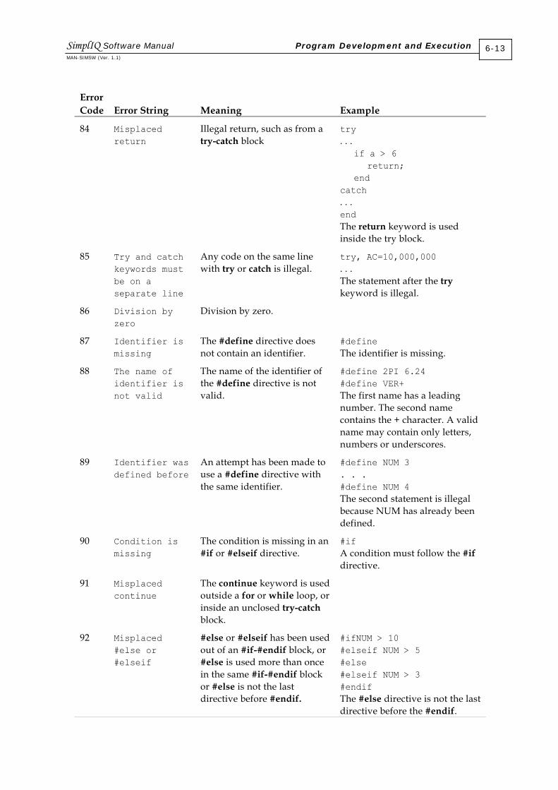
Error Code
Error String
Meaning
Example
84 Misplaced return
Illegal return, such as from a try-catch block
try . . . if a > 6 return; end catch . . . end The return keyword is used inside the try block.
85 Try and catch keywords must be on a separate line
Any code on the same line with try or catch is illegal.
try, AC=10,000,000 . . . The statement after the try keyword is illegal.
86 Division by zero
Division by zero.
87 Identifier is missing
The #define directive does not contain an identifier.
#define The identifier is missing.
88 The name of identifier is not valid
The name of the identifier of the #define directive is not valid.
#define 2PI 6.24 #define VER+ The first name has a leading number. The second name contains the + character. A valid name may contain only letters, numbers or underscores.
89 Identifier was defined before
An attempt has been made to use a #define directive with the same identifier.
#define NUM 3 . . . #define NUM 4 The second statement is illegal because NUM has already been defined.
90 Condition is missing
The condition is missing in an #if or #elseif directive.
#if A condition must follow the #if directive.
91 Misplaced continue
The continue keyword is used outside a for or while loop, or inside an unclosed try-catch block.
92 Misplaced #else or #elseif
#else or #elseif has been used out of an #if-#endif block, or #else is used more than once in the same #if-#endif block or #else is not the last directive before #endif.
#ifNUM > 10 #elseif NUM > 5 #else #elseif NUM > 3 #endif The #else directive is not the last directive before the #endif.
SimplIQ Software Manual Program Development and Execution MAN-SIMSW (Ver. 1.1)
6-13
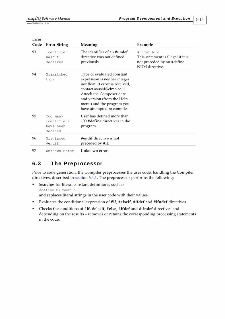
Error Code
Error String
Meaning
Example
93 Identifier wasn’t declared
The identifier of an #undef directive was not defined previously.
#undef NUM This statement is illegal if it is not preceded by an #define NUM directive.
94 Mismatched type
Type of evaluated constant expression is neither integer nor float. If error is received, contact [email protected]. Attach the Composer date and version (from the Help menu) and the program you have attempted to compile.
95 Too many identifiers have been defined
User has defined more than 100 #define directives in the program.
96 Misplaced #endif
#endif directive is not preceded by #if.
97 Unknown error Unknown error.
6.3 The Preprocessor
Prior to code generation, the Compiler preprocesses the user code, handling the Compiler directives, described in section 6.4.1. The preprocessor performs the following:
Searches for literal constant definitions, such as #define MYConst 5 and replaces literal strings in the user code with their values.
Evaluates the conditional expression of #if, #elseif, #ifdef and #ifndef directives.
Checks the conditions of #if, #elseif, #else, #ifdef and #ifndef directives and – depending on the results – removes or retains the corresponding processing statements in the code.
SimplIQ Software Manual Program Development and Execution MAN-SIMSW (Ver. 1.1)
6-14

6.4 Compiler Pragmas
6.4.1 Compiler Directives
6.4.1.1 #define
The #define directive may be used to assign a name to a literal string, in a manner similar to that of the C language.
Syntax: #define identifier token_string
The #define directive substitutes token_string for all subsequent occurrences of an identifier in the source file. The identifier is replaced only when it forms a token. For instance, identifier is not replaced if it appears in a comment, within a string or as part of a longer identifier.
The #define directive without identifier is illegal.
A #define without a token_string is not replaced. The identifier remains defined and can be tested using the #ifdef and #ifndef directives.
The token_string argument consists of a series of tokens, such as keywords, constants or complete statements. One or more space characters must separate token_string from identifier.
The legal identifier name may consist of a maximum of 32 characters. A valid name consists only of letters, underscores and numbers (not leading). The name is case sensitive, although uppercase identifiers are accepted.
The maximum admissible number of #define directives in the SimplIQ drive is 100.
When evaluating the token_string (refer to section 6.4.2), if the evaluation is successful, the identifier is replaced with the obtained value; otherwise, every appearance of the identifier is replaced with the token_string as a string.
The syntax that defines Compiler directives in the SimplIQ language differs from the C language in a number of ways. The redefinition of #define with the same identifier is illegal unless the second definition of #define appears after the first definition is removed with the #undef directive.
The token_string may contain identifiers of other #define directives as part of the expression. When such an expression is successfully evaluated, every occurrence of this identifier is replaced with the evaluation result even if the identifiers that are part of its token_string were removed with an #undef directive (described in Example 6 following).
Example 1: #define DEBUG_FLAG Defines the identifier DEBUG_FLAG.
SimplIQ Software Manual Program Development and Execution MAN-SIMSW (Ver. 1.1)
6-15

Example 2: #define ARR_LEN 10 Defines the identifier ARR_LEN as the integer constant 10. Each occurrence of ARR_LEN will be replaced by 10.
Example 3: #define ARR_LEN num+10 Defines the identifier ARR_LEN as the string num+10. The precompiler cannot evaluate token_string because num is not a constant expression. Each occurrence of ARR_LEN will be replaced by this string.
Example 4: #define DEBUG_FLAG . . . #define DEBUG_FLAG The first statement defines the identifier DEBUG_FLAG and the second statement is illegal because it redefines the #define with an already-defined identifier.
Example 5: #define DEBUG_FLAG . . . #undef DEBUG_FLAG . . . #define DEBUG_FLAG 1 The first statement defines the identifier DEBUG_FLAG and the second statement removes this identifier. The third statement defines DEBUG_FLAG again, and is legal because the previous definition of DEBUG_FLAG was removed by the #undef directive. This identifier has a token_string and each occurrence of DEBUG_FLAG will be replaced by 1.
Example 6: #define MAX_LEN 10 #define ARR_LEN MAX_LEN +10 . . . #undef MAX_LEN . . . int arr[ARR_LEN]; This example contains two identifiers with token_strings that have been successfully evaluated. The identifier ARR_LEN contains MAX_LEN as part of its constant expression. In the last statement, the identifier ARR_LEN will be replaced with 20 despite the fact that the identifier MAX_LEN was removed with the #undef directive.
SimplIQ Software Manual Program Development and Execution MAN-SIMSW (Ver. 1.1)
6-16

6.4.1.2 #if
The #if directive checks the conditional expression, as it does in the C language. If the specified constant expression following the #if has a non-zero value, it directs the Compiler to continue processing statements up to the next #endif, #else or #elseif. Afterwards, it skips to the statement following the #endif directive. If the conditional expression has a zero value, #if directs the Compiler to skip to the next #endif, #else or #elseif directive.
Syntax: #if constant-expression
The constant-expression is either an integer or a float constant expression.
Each #if directive in a source file must be matched with a closing #endif directive; otherwise, an error message is generated.
The #if, #elseif, #else and #endif directives can be nested in the text portions of other #if directives. Each nested #else, #elseif or #endif directive belongs to the closest preceding #if directive.
The #if directive must contain a constant-expression, which is evaluated to a single value; otherwise it causes an error.
Example: #if MAX_LEN > 10 #define REDUCE_MAX_LEN 10 #endif In this example, REDUCE_MAX_LEN will be defined as the integer constant 10 only if MAX_LEN is greater than 10; otherwise, it will not be defined at all.
6.4.1.3 #else
The #else directive, as in C, marks an optional clause of a conditional-compilation block defined by an #ifdef or #if directive.
Syntax: #else
The #else directive must be the last directive before the #endif directive. Only a single #else directive is allowed. The #else directive contains no conditions.
Example: #if MAX_LEN > 10 #define REDUCE_MAX_LEN 10 #else #define REDUCE_MAX_LEN 5 #endif In this example, REDUCE_MAX_LEN will be defined as the integer constant 10 only if MAX_LEN is greater than 10; otherwise, it will be defined as the integer constant 5.
SimplIQ Software Manual Program Development and Execution MAN-SIMSW (Ver. 1.1)
6-17

6.4.1.4 #elseif
The #elseif directive marks an optional clause of a conditional-compilation block defined by an #ifdef or #if directive.
Syntax: #elseif constant-expression
The directive controls conditional compilation by checking the specified constant expression. If the expression is non-zero, #elseif directs the Compiler to continue processing statements up to the next #endif, #else or #elseif directive and then to skip to the statement after #endif. If the constant expression is zero, #elseif directs the Compiler to skip to the next #endif, #else or #elseif. Up to 50 #elseif directives can appear between the #if and #endif directives.
As with the #if directive, the #elseif directive must contain a constant-expression, which is evaluated to a single value; otherwise it causes an error.
Example: #if MAX_LEN > 30 #define REDUCE_MAX_LEN 30 #elseif MAX_LEN > 20 #define REDUCE_MAX_LEN 20 #elseif MAX_LEN > 10 #define REDUCe_MAX_LEN 10 #else #define REDUCE_MAX_LEN 5 #endif The #if, #elseif and #else directives in this example are used to make one of four choices, based on the value of MAX_LEN. The constant REDUCE_MAX_LEN is set to 30, 20, 10 or 5, depending on the definition of MAX_LEN.
6.4.1.5 #endif
Each #endif directive must close an #if directive, in a manner similar to the C language.
Syntax: endif
The #endif directive without a previous #if directive generates an error.
6.4.1.6 #ifdef
The #ifdef directive, as in C, checks for the presence of identifiers defined with #define.
Syntax: #ifdef identifier
The #ifdef and #ifndef directives can be used anywhere that #if can be used. The #ifdef identifier statement is equivalent to #if 1 when identifier has been defined, and is equivalent to #if 0 when identifier has not been defined or has been undefined with the #undef directive.
SimplIQ Software Manual Program Development and Execution MAN-SIMSW (Ver. 1.1)
6-18

Example: #define DEBUG_FLAG . . . #ifdef DEBUG_FLAG printf((“Parameter is equal to %d”, debug_var); #endif In this example, the text between the #ifdef and #endif directives is compiled as DEBUG_FLAG was defined previously.
6.4.1.7 #ifndef
The #ifndef directive, as in C, checks for the absence of identifiers defined with #define.
Syntax: #ifndef identifier
The #ifndef directive checks for the opposite of the condition checked by #ifdef. If the identifier has not been defined (or its definition has been removed with #undef), the condition is true (nonzero). Otherwise, the condition is false (0).
Example: #ifndef DEBUG_FLAG #define DEBUG_FLAG #endif In this example, DEBUG_FLAG will be defined only if it has not been defined previously. It prevents the possible redefinition of DEBUG_FLAG.
6.4.1.8 #undef
The #undef directive, as in C, removes the current definition of the specified name. All subsequent occurrences of the name are processed without replacement.
Syntax: #undef identifier
The #undef directive must be paired with a #define directive in order to create a region in a source program in which an identifier has a special meaning.
Unlike the #undef directive in C, with the SimplIQ drive, you cannot apply #undef to an identifier that has not been previously defined. Repetition of the #undef directive with the same identifier is illegal.
Example: #define DEBUG_FLAG . . . #undef DEBUG_FLAG In this example, the #undef directive removes the definition of DEBUG_FLAG, previously created by the #define directive.
SimplIQ Software Manual Program Development and Execution MAN-SIMSW (Ver. 1.1)
6-19

6.4.2 Evaluating Expressions Used in Compiler Directives
The #define, #if and #elseif directives may contain constant expressions for evaluation. Such expressions – which may be either simple (a single number) or complex (a combination of operations) – must be evaluated to a single number.
A valid expression can operate only with:
Numbers
Values of the #define directive.
If the expression contains the identifier of the #define directive, the identifier must have a successfully-evaluated token_string.
The syntax of the expression of a pre-compilation directive differs from the syntax of other expressions in that it has the following limitations:
It cannot contain global or local variables; only constant values are valid.
It cannot use any system or user functions, or system commands.
Only integer and float data types are allowed. Arrays and array members are illegal.
An expression in a pre-compilation directive uses the same operators as other expressions in the user program. The valid operators are:
Calculating operators: * / = - %
Logical operators: && ║
Comparison operators: == != < > <= >=
Bitwise operators: & | << >>
Unary logical operators: !
Unary bitwise operators: ~
A detailed description of the operators is given in section 4.2.2. The data type of the evaluation result depends on the operation and the type of operands. The result of logical, bitwise and comparison operations is always integer. With calculating operations, if both operands are integers, the result is integer; otherwise, the type is float.
6.5 Downloading and Uploading a Program
In this step of program development, communication between the Composer and the SimplIQ drive must be established.
After successfully compilation, the compiled code can be downloaded to the SimplIQ drive. This step is supported by the Composer IDE. Before each download, the Composer automatically clears the flash memory sector, which is used for saving the user program.
The serial flash performs downloads and uploads using two commands: DL and LS. Both commands use the auxiliary LP command, which is a vector integer command. The CP command can be used to clear the user flash area, and the CC command can be used to checksum-verify the program, and set the program read flag.
SimplIQ Software Manual Program Development and Execution MAN-SIMSW (Ver. 1.1)
6-20

After a successful download, global variables can be used — for monitoring and modifications — from an external terminal such as the Composer Smart Terminal.
6.5.1 Binary Data
The SimplIQ drive flash memory is interfaced with binary data. Sending the binary data on the RS-232 lines is problematic, because they do not differentiate between data and delimiters.
Characters that are problematic for sending on RS-232 lines are:
All numbers from 128 to 255
All possible terminators: 0, <CR>, <LF>, semicolon (;) and comma (,)
Equals sign (=)
Backspace
<ESC>
In order to prevent this problem, a hexadecimal binary format is used during data upload and download, although this increases the amount of data to be transmitted.
Every byte in hexadecimal format consists of two numbers (such as 0x12), considered to be a single character. For example, the 8-bit number 0x12 in hexadecimal binary format is the sequence of two characters: 1 and 2.
The representation of numbers in the DSP flash memory differs from its representation inside a personal computer.
The 8-bit number is represented the same way.
The 16-bit number, represented in hexadecimal format as equal to 0x1234, is represented in the DSP memory in the following two bytes: Byte 1 equals the value 0x12 in hexadecimal form Byte 2 equals the value 0x34 in hexadecimal form
The 32-bit number, represented in hexadecimal format as equal to 0x12345678, is represented in the DSP memory in the following four bytes: Byte 1 equals the value 0x56 in hexadecimal form Byte 2 equals the value 0x78 in hexadecimal form Byte 3 equals the value 0x12 in hexadecimal form Byte 4 equals the value 0x34 in hexadecimal form
Binary data to be loaded to the serial flash is represented in this format.
Examples:
Number in Hexadecimal Form in PC
Sequence of Characters in Hex Binary Form for Transmission
0x12 12
0x1234 1234
0x12345678 56781234
SimplIQ Software Manual Program Development and Execution MAN-SIMSW (Ver. 1.1)
6-21

6.5.2 Auxiliary Upload/Download Commands
6.5.2.1 The LP[N] Command
This command sets the properties of the serial flash data upload and download; it is used together with the DL and LS commands (sections 6.5.3.1 and 6.5.4.1).
LP[1] defines the byte (out of 128K bytes in the flash) at which the next action should start.
LP[2] defines how many byte to send (LS command).
LP[3] specifies the start address (bytes) of the user/factory program partition in the flash.
LP[4] specifies the size (bytes) of the user/factory program partition in the flash.
The TW[11] parameter indicates the type of program partition: user or factory.
6.5.2.2 The CP Command
This command clears the entire user area in the serial flash. The clearing operation may take a significant amount of time. CP sets the Program Valid flag to -1.
Failures in executing the CP command may occur if:
The motor is on.
A program is running.
6.5.2.3 The CC Command
The CC=xxxx command performs the following:
Reads the actual length of the user partition from the flash memory table of contents (TOC).
Calculates a 32-bit checksum for the entire user partition. The checksum is calculated by totaling all the consecutive 2-byte sequences (short integer numbers) that occupy user program space, along with the checksum number itself. The total result must be zero to pass.
If the resulting checksum matches xxxx, sets the Program Ready flag (CC returns 1) and copies functions and variable symbol tables from the user partition to the internal DSP flash memory. If the checksum does not match xxxx, an error code is issued (CC returns 0).
Failures in executing the CC command may occur if:
The actual length of the TOC is less than two flash pages, or if it exceeds the user program address limit.
The calculated checksum does not match xxxx.
SimplIQ Software Manual Program Development and Execution MAN-SIMSW (Ver. 1.1)
6-22

6.5.3 Downloading a Program
6.5.3.1 The DL Command
The DL command downloads data to the serial flash memory of the drive. The command is used primarily to download compiled user programs to the drive. When downloading to a non-protected area in the flash, the process is as follows: LP[1]=start; DL##xxxxxxxxx<ESC>CS; where: xxxxxxxxx denotes the escape-sequenced data payload. start denotes the byte address in the user program flash. CS denotes the 16-bit checksum for the message, including DL##.
The DL process takes time to proceed, because it needs to burn and verify.
Failures in executing the DL command may occur if:
An attempt is made to write to a protected area of the flash. While the DL may begin to write legally to the flash, its last bytes may attempt an illegal (protected) write. In any such case, the DL command will be rejected and the contents of the serial flash will be unpredictable.
DL is used when the motor is on.
DL is used when a program is running.
There is a faulty checksum. In this case, DL will be rejected but no harm will be caused.
A verify error occurs. If DL attempts to write to an error in the flash that was written to previously, the write will probably fail due to a Verify error. In this case, the contents of the flash will be unpredictable and it will need to be cleared and completely rewritten.
The DL string is too long. The maximum length of a DL string is 500 bytes, due to internal SimplIQ drive limits.
The Program Valid flag is not -1. In this case, the DL command will not be executed (CP must be issued before DL).
6.5.3.2 The Program Download Process
In order to download a program image to the SimplIQ drive, perform the following procedure:
1. Read the location (loc) and the length of the user code partition, using the LP[3] and LP[4] commands.
2. Verify that your image block will fit inside the allocated space.
3. Clear the program flash using the CP command.
4. Download your image file using the following sequence: LP[1]=loc; DL##…100 bytes of payload LP[1]=(loc+100) DL##…next 100 bytes of payload . . . and so on until the end of the image
SimplIQ Software Manual Program Development and Execution MAN-SIMSW (Ver. 1.1)
6-23

5. Use the CC=checksum command to declare the end of loading and to verify the entire download process.
6.5.4 Uploading a Program
6.5.4.1 The LS Command
The LS command is used to upload a program that resides in the drive flash, for backup or for further editing. This option is disabled when a program is running. After program upload, the user can modify it and then return to the compilation step. When uploading from a non-protected area in the flash, the process is as follows: LP[1]=start; LP[2]=payload net length xxxxxxxxx<ESC>CS; where: xxxxxxxxx denotes the escape-sequenced data payload. start denotes the byte address in the user program flash. CS denotes the 16-bit checksum for the message.
Failures in executing the LS command may occur if the LS sequence (including <ESC>s) exceeds 200 characters (internal SimplIQ buffer management limit). The LS output will be terminated with the proper checksum and terminator. The data transmitted in the payload will be good and meaningful, but not to the defined length.
6.5.4.2 The Program Upload Process
In order to upload a program image from the SimplIQ drive, perform the following procedure:
1. Read the location (loc) and the length (len) of the user code partition from the main TOC, using the LP[3] and LP[4] commands.
2. Upload your image file using the following sequence: LP[1]=loc; LP[2]=100 Use LS to get the next 100 bytes of the payload. LP[1]=(loc+100); Use LS to get the next 100 bytes of the payload. . . . and so on until the end of the image.
6.6 Program Execution
Presently, it is not possible to run more than one task, the virtual machine, simultaneously. This will, however, be possible in the future.
The following sections describe how to run a program.
SimplIQ Software Manual Program Development and Execution MAN-SIMSW (Ver. 1.1)
6-24

6.6.1 Initiating a Program
A program is initiated by the XQ command, which indicates at which label execution should begin.
The XQ command does not reset program variables; initial values for all variables must be set by the user.
The XQ command clears the call stack, kills any pending automatic routines and clears the interrupt mask. For a description of the XQ command, refer to section 6.7.1.
6.6.2 Halting and Resuming a Program
The HP Interpreter command can be used to stop execution of the user program and the automatic routines. HP freezes the status of the program and does not reset it. A later XC command can resume the program from the instruction at which the program was halted. Pending interrupts will remain pending.
Example 1: MO=1; Start motor. JV=2000; Set jog speed. ##LOOP; Repetitive task BG; wait(1000) Wait and switch direction. JV=-JV; goto##LOOP; Repeat.
This program indicates that the motor should travel at 2000 counts/second for one second, then reverse direction for one second, and then continue to travel back and forth forever.
If the HP command is applied when the program is waiting (executing the wait(1000) instruction), the motor will continue to travel at the same direction for an unlimited time.
An XC command reverses the direction immediately, because the waiting time has already elapsed.
SimplIQ Software Manual Program Development and Execution MAN-SIMSW (Ver. 1.1)
6-25

Example 2: A servo axis in a machine has two different tasks to perform, in two different machine modes. The following routine implements the two tasks.
##TASK1;
##LOOP; Repetitive task 1.
… Task 1 body.
goto##LOOP; Repeat task 1.
##TASK2;
##REP; Repetitive task 2
… Task 2 body.
goto##REP; Repeat task 2.
The first task is invoked by XQ##TASK1. In order to switch to the second task, the first task must be killed before: HP; XQ##TASK2;
6.6.3 Automatic Program Execution with Power Up
If the autoexec function is included in the user program, the program line following function declaration will be performed at power up.
6.6.4 Save to Flash
Because a program is downloaded to a non-volatile memory, it is always saved. Therefore, information is not lost in case of power down. As noted in section 6.5.2.2, the CP command clears the entire user area in the flash and the running program must be killed (not halted) before the command is issued.
6.7 Debugging
This procedure enables a user to debug a program that is downloaded to the flash memory of the SimplIQ drive. This step may be useful when developing the user program and examining the user flow.
6.7.1 Running, Breaking and Resuming
The XQ command starts program execution from a label or executes a function, as follows:
XQ##MYFUNCTION(a,b,c) runs the function MYFUNCTION(a,b,c).
XQ cannot return values from a function.
XQ##LABEL runs from ##LABEL.
XQ runs from the start of the user program code.
XQ without a parameter is illegal.
XQ does not return a value.
SimplIQ Software Manual Program Development and Execution MAN-SIMSW (Ver. 1.1)
6-26

Notes:
XQ without a label or function name is designed to run a program written in the Elmo Saxophone or Clarinet; that is, without function definitions, local variables and so on. If the program starts from a function definition, the XQ command without a label or function name causes an error to occur. If the function starts from a label, the dummy start label is inserted into the Function Symbol table and execution begins at the start of the program.
XQ does not change the current values of global variables; the initial values of global parameters must be set by the programmer.
KL=0 kills all virtual machines, if any are running. KL stops the motor. HP halts all virtual machines; they can be continued later by the XC command. If HP halts inside a wait statement, the wait time stops running while the program is halted. XC continues all virtual machines.
6.7.2 The Elmo Studio
The Elmo Studio IDE provides the environment for debugging a user program. It includes these functions:
Error reporting Step out
Pause and continue a program Step over
Breakpoints Watch global variables
Run to cursor Watch auto/local variables
Step in View call stack functions
6.7.3 The DB Command
The DB command was designed for use with the Elmo Studio IDE. Therefore, users of the Elmo Studio require no further knowledge of its functionality. The information in this section is provided for advanced programmers and may be changed without further notice.
This command assists in analyzing the user program, enabling the user to:
Set and remove breakpoints.
Get information about existing VAC machines.
Get the running status of the program.
Get the error status of a VAC machine.
Ask for or change values of local variables.
Get the program call stack.
The DB command should be used by IDE managers. The syntax of the command is strict: Spaces and white characters are not allowed, in order to simplify the treatment of the command. All values must be numbers; expressions are illegal.
SimplIQ Software Manual Program Development and Execution MAN-SIMSW (Ver. 1.1)
6-27

6.7.4 Machine Status
The DB##MS command returns the status of all existing VAC machines.
Syntax: DB##MS
This command returns a string in hexadecimal binary format containing a 16-bit number. Every 4 bits characterize the status of the VAC machine; therefore, the command can give the status of a maximum of four VAC machines. The most significant bit (bit 4) is dedicated to run-time errors. If it is set to 1, it indicates that a run-time error has occurred. The DB##ES[N] command reports further details about the specific VAC errors and resets this bit. If the run-time error bit is 0, no run-time error has occurred or else it has been reset by a previous DB##ES[N] command.
The remaining least significant bits (0…3) of the returned status use the following values: 0: Halted 1: Running 2: Idle/Not running 3: Aborted/Fault 4: Does not exist
6.7.5 Program Status
The DB##PS command returns the status of the user program.
Syntax: DP##PS[N] where N is a handle of a specified VAC machine.
The DB##PS command returns a string containing hexadecimal binary data with the following information:
Name
Meaning
Data Type
Size in Bytes
1 Status Running status (section 6.7.4). Signed short 2
2 Error code Last error code or 0 for no error (section 6.7.6).
Signed short 2
3 Program counter (PC)
Program counter of current executing line.
Unsigned short 2
4 Base pointer (BP) Current base pointer, which is the saved stack pointer marking the function entry point. BP is used to reference local variables of a function.
Unsigned short 2
5 Stack pointer (SP) Current stack pointer. Unsigned short 2
The non-zero error code indicates that an error has occurred.
SimplIQ Software Manual Program Development and Execution MAN-SIMSW (Ver. 1.1)
6-28
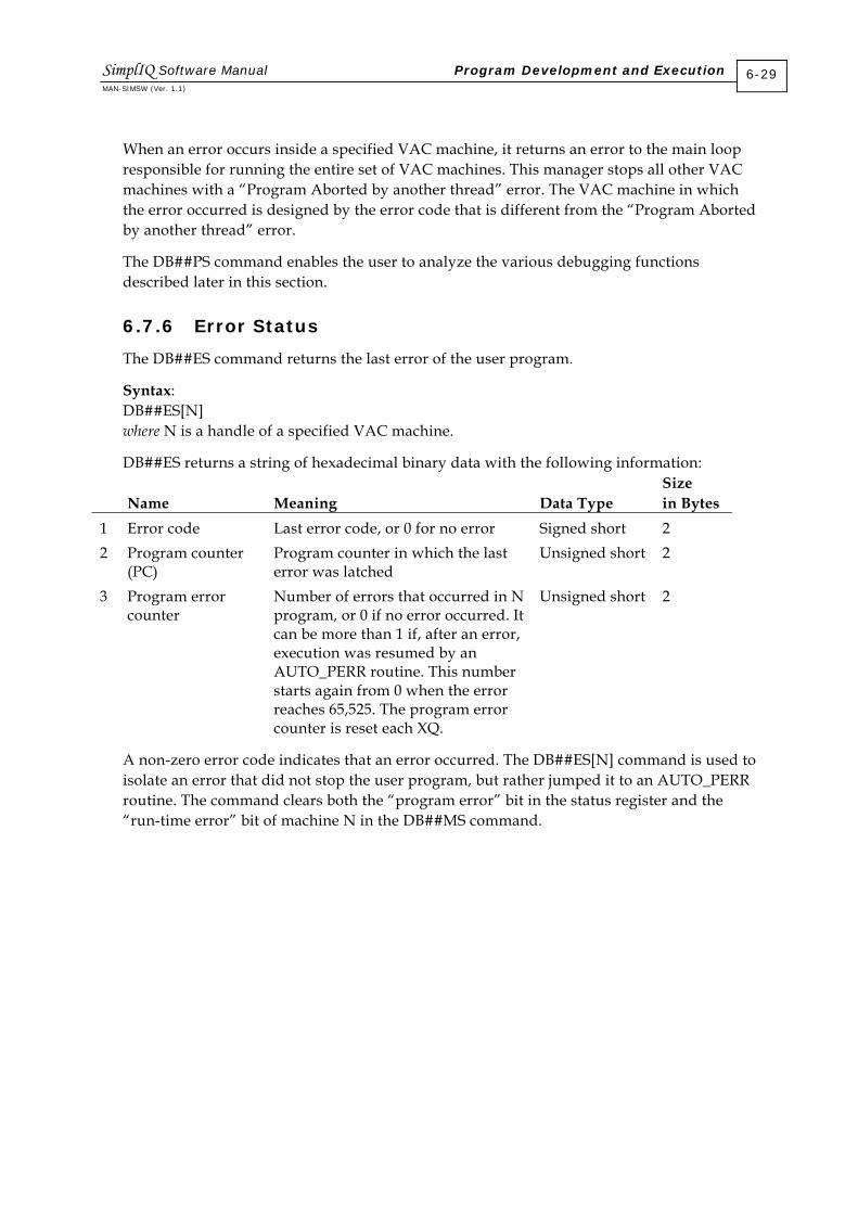
When an error occurs inside a specified VAC machine, it returns an error to the main loop responsible for running the entire set of VAC machines. This manager stops all other VAC machines with a “Program Aborted by another thread” error. The VAC machine in which the error occurred is designed by the error code that is different from the “Program Aborted by another thread” error.
The DB##PS command enables the user to analyze the various debugging functions described later in this section.
6.7.6 Error Status
The DB##ES command returns the last error of the user program.
Syntax: DB##ES[N] where N is a handle of a specified VAC machine.
DB##ES returns a string of hexadecimal binary data with the following information:
Name Meaning
Data Type
Size in Bytes
1 Error code Last error code, or 0 for no error Signed short 2 2 Program counter
(PC) Program counter in which the last error was latched
Unsigned short 2
3 Program error counter
Number of errors that occurred in N program, or 0 if no error occurred. It can be more than 1 if, after an error, execution was resumed by an AUTO_PERR routine. This number starts again from 0 when the error reaches 65,525. The program error counter is reset each XQ.
Unsigned short 2
A non-zero error code indicates that an error occurred. The DB##ES[N] command is used to isolate an error that did not stop the user program, but rather jumped it to an AUTO_PERR routine. The command clears both the “program error” bit in the status register and the “run-time error” bit of machine N in the DB##MS command.
SimplIQ Software Manual Program Development and Execution MAN-SIMSW (Ver. 1.1)
6-29
6.7.7 Setting and Clearing Breakpoints
The SimplIQ drive supports up to six breakpoints simultaneously: five user-defined breakpoints and one for internal IDE use. Breakpoints can be set any time and any place, regardless of if the program is running or not.
Syntax: DP##BP=xxx Sets a breakpoint at program counter xxx DB##BP=xxx,n Sets a breakpoint at line program counter, activated only after n repetitions DB##BC=xxx Removes a breakpoint at the program counter DB##BC Removes all breakpoints where: xxx is 4 bytes unsigned long. n is 2 bytes signed short.
6.7.8 Continuing the Program
When the program reaches a breakpoint, it stops running the entire set of existing virtual machines. To continue running the program, the DB##GO is used.
Syntax: DB##GO and DB##GO[N] where N is a handle of a specified VAC machine.
The program continues to run from the current program counter. The DB##GO command continues running all VAC machines, while the DB##GO[N] command continues running the specified VAC machine.
In order to determine which existing VAC machine has a program counter equal to the program counter of the breakpoint, the DB##MS command must first be sent in order to determine which VAC machines exist. Afterwards, the DB##PS command must be sent for all existing VAC machines in order to get the program counter for comparison with the breakpoint program counter. It is possible that several VAC machines will have a program counter equal to the breakpoint program counter; in such a case, they may all be chosen as the specified VAC machine.
6.7.9 Single Step
When a program reaches a breakpoint, the user may decide to continue running in single-step mode.
6.7.9.1 Run to Cursor
In this situation, the IDE sets a fake breakpoint with a single repetition. When the breakpoint is reached, it must be removed from the breakpoint list. There is no need to define a special debug command for this.
SimplIQ Software Manual Program Development and Execution MAN-SIMSW (Ver. 1.1)
6-30

6.7.9.2 Step Over
The DB##SO command executes a step over by running to the nearest end of line.
Syntax: DB##SO[N] where N is a handle of the specified VAC machine.
This command is implemented inside the SimplIQ drive, using the following process:
Save the current base pointer.
Start the loop.
Run to the nearest end of line.
Compare the current base pointer with the saved base pointer.
If both are the same, jump to the end of the loop (step over); otherwise, go to the start of the loop.
End of loop.
When the nearest end of line is reached, the VAC machine enters the halt state. In case of a jump, infinite loop or other reason within the line execution, the program may not reach the end of line and will simply run and not enter the halt state.
6.7.9.3 Step In
The DB##SI command executes a step in by entering a function body and running to the nearest end of line.
Syntax: DB##SI[N] where N is a handle of a specified VAC machine.
This command is implemented inside the SimplIQ drive, using the following process:
Start the loop.
Run to the nearest end of line.
End of loop.
When the nearest end of line is reached, the VAC machine enters the halt state.
6.7.9.4 Step Out
The DB##SU command executes a step out, returning from the function body and running up to the nearest end of line.
Syntax: DB##SU[N] where N is a handle of a specified VAC machine.
This command is implemented inside the SimplIQ drive, using the following process:
Save the current base pointer.
Start the loop.
SimplIQ Software Manual Program Development and Execution MAN-SIMSW (Ver. 1.1)
6-31

Run to the nearest end of line.
Compare the current base pointer with the saved base pointer.
If the current base pointer is less than the saved base pointer, the step is out: jump to the end of the loop. Otherwise, go to the start of the loop.
End of loop.
When the nearest end of line is reached and the current base pointer is less than the saved base pointer, the VAC machine enters a halt state. Otherwise, it simply runs and does not enter the halt state.
6.7.10 Getting Stack Entries
The DB##GS command returns relevant entries of the stack.
Syntax: DB##GS[N]=N1,N2 where: N is a handle of a specified VAC machine whose stack is queried. N1 is an index of the first stack entry. N2 is an index of the last stack entry (not inclusive).
The command returns a string containing hexadecimal binary data with a sequence of stack entries from N1 to N2. If a single stack entry is of interest, then N2 = N1+1.
The command, which is very useful during debugging, returns a string in the hexadecimal binary format. Every stack entry contains the following fields:
Name
Meaning
Data Type
Size in Bytes
1 value Stack entry value Float or long, depending on type
4
2 type Type of stack entry: 0 for long, 1 for float Signed short 2
3 unused Offset for alignment Signed short 2
6.7.11 Setting the Stack
The DB##ST command sets a stack entry, which must be a local variable or an input/output argument of the function.
Syntax: DB##ST[N]=N1,N2 where: N is a handle of a specified VAC machine (2 bytes, signed short). N1 is a stack pointer (2 bytes, signed short). N2 is a new variable value (4 bytes, long or float).
In order to change a value of a local variable, DB##SS sets a new value to the relevant stack entry for a specified VAC machine. The type of stack entry is set according to the type of value that is sent.
SimplIQ Software Manual Program Development and Execution MAN-SIMSW (Ver. 1.1)
6-32
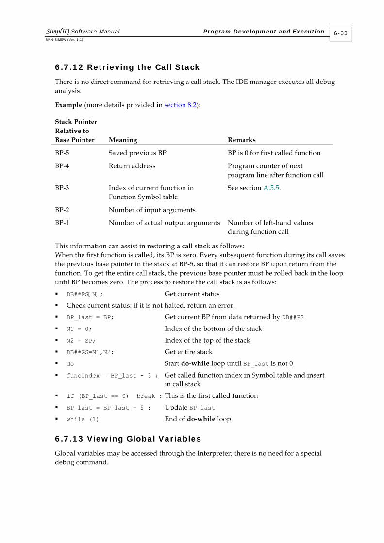
6.7.12 Retrieving the Call Stack
There is no direct command for retrieving a call stack. The IDE manager executes all debug analysis.
Example (more details provided in section 8.2):
Stack Pointer Relative to Base Pointer
Meaning
Remarks
BP-5 Saved previous BP BP is 0 for first called function
BP-4 Return address Program counter of next program line after function call
BP-3 Index of current function in Function Symbol table
See section A.5.5.
BP-2 Number of input arguments
BP-1 Number of actual output arguments Number of left-hand values during function call
This information can assist in restoring a call stack as follows: When the first function is called, its BP is zero. Every subsequent function during its call saves the previous base pointer in the stack at BP-5, so that it can restore BP upon return from the function. To get the entire call stack, the previous base pointer must be rolled back in the loop until BP becomes zero. The process to restore the call stack is as follows:
DB##PS[N]; Get current status
Check current status: if it is not halted, return an error.
BP_last = BP; Get current BP from data returned by DB##PS
N1 = 0; Index of the bottom of the stack
N2 = SP; Index of the top of the stack
DB##GS=N1,N2; Get entire stack
do Start do-while loop until BP_last is not 0
funcIndex = BP_last - 3 ; Get called function index in Symbol table and insert in call stack
if (BP_last == 0) break ; This is the first called function
BP_last = BP_last - 5 : Update BP_last
while (1) End of do-while loop
6.7.13 Viewing Global Variables
Global variables may be accessed through the Interpreter; there is no need for a special debug command.
SimplIQ Software Manual Program Development and Execution MAN-SIMSW (Ver. 1.1)
6-33

6.7.14 Viewing Local Variables
Local variables cannot be accessed through the Interpreter, and there is no special debug command for this. The IDE manager can access local variables by using existing debug commands and analyzing their results as when retrieving a call stack. The procedure for doing this is as follows:
DB##PS[N]; Get current status
Check current status: If it is not halted, return an error.
DB##GS[N]=BP-3,BP-2; Get an index of the function in Function Symbol table, located in the stack at (BP - 3).
Search in the Variable Symbol table for all local variables of this function. These variables are sorted first according to an index of the function to which they belong and afterwards according to variable name (case sensitive). The Symbol table contains full information about type and location of the variable (section A.5.6).
To view a specified local variable, use DB##GS command.
To set a new value of a specified local variable, use the DB##ST command.
The LINK command allocates place for local variables, inserting N entries at the top of the stack and resetting them, where N is the number of local variables. Usually, LINK is the first opcode of the function. If a local variable is accessed before the opcode LINK is executed, the relevant stack entries will contain garbage.
SimplIQ Software Manual Program Development and Execution MAN-SIMSW (Ver. 1.1)
6-34

Chapter 7: Development Aids
SimplIQ hardware and software include a number of features that facilitate application development: The SimplIQ drive’s built-in simulation capability enables the user to develop large parts
of the application from the desktop, without even connecting the SimplIQ drive to a motor.
Controller sampling time can be optimized for best performance.
The recorder is a major auxiliary tool for viewing what occurs inside an application. A number of debugging tools enable you to determine the source of errors in the SimplIQ
drive operation.
7.1 Wizard Mode Password
The SimplIQ drive includes a number of protected commands to ensure safety when running the SimplIQ drive. For example, a password is required for under-voltage protection, to ensure that your actions are not accidental.
To use the Wizard mode with the SimplIQ drive, enter the password TP[6]=1. In this mode, the SimplIQ drive recognizes its full instruction set, including commands for simulation, tuning experiments or factory software tests. To exit Wizard mode, enter TP[6]=0.
7.2 Simulation
You can use the extensive built-in simulation capabilities of the SimplIQ drive to:
Design and run motion reference signals without a connected motor.
Apply all digital inputs without connecting to any physical input device.
Override the hardware readouts of the digital inputs.
Apply a motor fault and verify the correct fault handling.
Apply a follower reference without connecting any encoder signals to the auxiliary input.
Apply analog inputs for referencing speed or torque or any other purpose, without connecting to any analog voltage source.
7.2.1 Starting the Motor without a Motor Power Supply
The SimplIQ drive is protected against under voltage, preventing it from starting the motor without a DC supply. In order to bypass this under-voltage protection, use the following command: TW[34]=0 (password protected).
The setting is volatile and at the next power-up, the SimplIQ drive will revert to its under-voltage protection.
SimplIQ Software Manual MAN-SIMSW (Ver. 1.1)
7-1
Once you have entered the password, you enter MO=1 to initiate “motor on” state, in which you can run controller reference commands. Of no motor is connected to the SimplIQ drive, the drive may refuse to accept MO=1, claiming that all Hall sensors read the same. In such a case, you may use one of the following remedies:
Set CA[28]=1 to define a DC motor that does not require Hall sensors.
Change CA[1] so that one Hall sensor is software-inverted.
Define CA[20]=0, “No Halls are present.”
To restore under-voltage protection, enter: TW[34]=1024
Notes: To run simulation only, disconnect the power supply from the SimplIQ drive. If a
motor and a power supply are connected to the drive, the motor will run normally, despite TW[34].
When TW[34]=0, an auto-phasing process will indicate success and continue to MO=1 regardless of its actual success. Do not set TW[34]=0, CA[20]=0, MO=1 with the motor and power supply connected because the auto-phasing process can fail without being noticed, resulting in unstable feedback control.
7.2.2 Applying Digital Inputs without Connecting to an Input Device
The IL[N] command defines the functionality of the digital input pin. IL[1] defines the behavior of digital input #1, IL[2] defines the behavior of digital input #2 and so on. In addition to the pin functionality, the IL[N] command defines if the corresponding digital input signal is read from the hardware or if it is software simulated. For details, refer to the IL[N] command section of the SimplIQ Command Reference Manual.
7.2.3 Applying a Motor Fault
In order to test exception handling, you can simulate a motor fault by entering: TW[32]=n (password protected)
The SimplIQ drive will abort the “motor on” (MO=1) state and the motor fault (MF) report will be n.
7.2.4 Applying a Follower Reference without Connecting an Encoder Signal to the Auxiliary Input
Using a simulated auxiliary encoder signal, you can test how your position follower or ECAM or speed follower behaves without any external encoder connection. To do so, enter: TW[35]=n (password protected)
SimplIQ Software Manual Development Aids MAN-SIMSW (Ver. 1.1)
7-2

The auxiliary encoder will read a simulated encoder signal with a speed of n counts/second. The desired speed n may be positive or negative. The auxiliary encoder readout will connect to the hardware again at the next power on or when you enter TW[35]=0.
Do not use TW[35]=n when the auxiliary encoder serves for feedback (UM=4) because this result in control instability.
7.2.5 Applying Analog Inputs without Connecting to an Analog Voltage Source
Using a simulated analog signal, you can test the response of the current or speed controller to analog inputs, or you can test the response to any analog input.
You may define a sequence of analog input readouts that run cyclically from a value that you define. The readout values are in the ZX[N] array. MP[1] and P[2] define the lowest and the highest N values to use. TW[38]=n starts the sequence running as analog input, starting with index n (or from MP[1] if n is out of the range [MP[1]…MP[2]]).
For example, to have the analog input see the sequence: 1,2,3,4, 1,2,3,4 1,2,3,4 . . . you should program: ZX[1]=1; ZX[2]=2; ZX[3]=3; ZX[4]=4; TW[38]=1;
The analog input readout will reconnect to the hardware at TW[38]=0, or at the next power on.
A new ZX[N] sample is used every torque sampling time. Therefore, with UM=1, the analog input for the previous sample sequence will be: 4,8,12,16, 4,8,12,16, 4,8,12,16 . . .
With UM=2, the analog input is averaged to yield a new reading every sampling time of the speed controller, which is twice the sampling time of the torque controller.
At the speed controller input, the following sequence will be seen: 6,14, 6,14, . . . (6 is the mean of 4 and 8; and 14 is the mean of 12 and 16).
With UM=3, 4, 5, the analog input is averaged to yield a new reading every sampling time of the position controller, which is four times the sampling time of the torque controller. At the position controller input, the following sequence will b seen: 10,10 . . . (10 is the mean of 4, 8, 12 and 16).
Do not use TW[38]=n when the analog input serves for feedback (CA[23]=5) because this may result in control instability.
SimplIQ Software Manual Development Aids MAN-SIMSW (Ver. 1.1)
7-3

7.3 Optimizing the Controller Sampling Time
Selecting a controller sampling time is a compromise between the following:
Possible control bandwidth
Maximum rate of CAN message acceptance
Maximum communication baud rate
Minimum latency for interpreter response
Maximum user program speed
The smaller the sampling time, the better the control performance. For mechanically ideal plants, the achievable speed controller bandwidth (with reasonable gain and phase margins) is approximately:
12000BWTS
=
which is approximately 120 Hz for a sampling time of 100 microseconds, and 170 Hz for a sampling time of 70 microseconds. The bandwidth increases slightly with the closure of the position loop.
For a low sensor resolution (speed always below 10,000 counts/second) or for moderate control performance requirements, a larger sampling time is tolerable. For extreme control performance, decrease the sampling time.
A lower sampling time implies a higher RS-232 baud rate. The SimplIQ drive can always operate at a baud rate of 57,600, while it can operate at a baud rate of 115,200 for TS=80 or less. Lower sampling times also imply that a larger number of CAN messages can be sent to the SimplIQ drive without loss. The maximum continuous CAN message acceptance rate is one message per 4 TS (bursts of up to eight messages can be accepted at the full CAN bus rate of 1 Mbaud/second). However, lower sampling times imply a greater CPU load, which causes the interpreter and the user program to operate at a slower rate. The “interpreter” includes the RS-232 interpreter, CAN SDO handling and CAN receive PDO (other than CAN high-speed motion commands) handling.
The CPU load is not only a function of the sampling time. DC motors consume less CPU load than brushless motors. UM=4 and 5 loads the CPU the most, while UM=2 loads it less and UM=1 and 2 the least. The specific design of the controller and sensor filters also affects the CPU load.
An extreme CPU load (not likely at TS-70 unless a very large control filter is being implemented) can cause a real-time overflow in the SimplIQ drive; it can be corrected by setting TS to a new value.
The WI[7] command tests for the CPU load and reports the percentage of CPU power remaining for the interpreter and the user program. A value no smaller than 25 is recommended for WI[7]. In order to use a smaller WI[7] value, the sampling time should be increased.
SimplIQ Software Manual Development Aids MAN-SIMSW (Ver. 1.1)
7-4

7.4 The Recorder
The SimplIQ drive recorder mechanism enables the user to record up to eight signals simultaneously. The recorded signals can be uploaded to the host through the communication connection, for presentation and analysis. SimplIQ drives operating with CAN have two communication lines: CAN and RS-232. This arrangement enables the recorder to use one line for performance monitoring while the machine host uses the other line to control the SimplIQ drive in its normal context.
This section explains how to define the recorder parameters for the SimplIQ drive, how to launch and trigger the recorder and how to fetch the recorded data. The details need not be of interest to most SimplIQ drive users, because the Composer application normally operates the recorder through a user-friendly interface.
The list of recordable signals supported by the SimplIQ drive is stored internally and can be retrieved by the host. (Refer to the LS and LP commands in the SimplIQ Command Reference Manual.) In addition, the SimplIQ drive can record user-program variables for tracing the progress of user programs without interrupting them.
The following commands are relevant to the recording process:
Command Description
BG, BT, IL[N] Begins motion using software or hardware command. Start of motion may be used to trigger the recorder.
BH Uploads recorder results.
LS Loads a record from the serial flash memory, in order to retrieve the list of recorder signals.
RC Defines which of mapped signals should be recorded.
RG Recorder gap: specifies sampling rate of the recorder.
RL Recorder length.
RP[N] Recorder parameters: defines which event will trigger the recorder, and the trigger position. Also defines basic time quantum for recorder (TS or four times TS) and data to be uploaded to host by next BH command.
RR Launches recorder and reads back its status.
RV Signal mapping: maps the IDs of the recordable signals to logical IDs that the recorder can reference.
SR Status register, which indicates the status of the recorder: idle, armed, triggered and recording, or ready with data.
TS Sampling time, the basic resolution of recorder.
WI[21] Actual amount of recorded data.
Table 7-1: Commands Relevant to the Recorder
SimplIQ Software Manual Development Aids MAN-SIMSW (Ver. 1.1)
7-5

7.4.1 Recorder Sequencing: Programming, Launching and Uploading Data
In order to activate the recorder, it must first be programmed to indicate which signals should be recorded, at what resolution and what will trigger the recording event. A number of limitations apply to programming the recorder: The recorder cannot be programmed while it is armed or recording. It must first be
stopped, or “killed” (RR=-0). Modifying the recorder programming invalidates any previously recorded data. Be sure
to upload all data that you need before programming the recorder.
After it is programmed, the recorder can be launched by: RR=1 Arms recorder to trigger at next start of motion RR=2 Starts recording immediately RR=3 Arms recorder to start recording at next trigger event
To poll the status of the recorder, use the RR and SR commands. After the recorder data is ready, use the BH command to upload the data.
7.4.2 Signal Mapping
The recorder can record a range of different signals. The first 16 signals — listed in the following table — are compatible with other Elmo drives.
Signal ID
Signal Name (Command)
Length; Type
Description
1 Main speed (VX) Long Float
Speed of main feedback sensor, in counts/second.
2 Main position (PX) Long Integer
Cumulative position of main feedback sensor, in counts.
3 Position command (DV[3]) Long Integer
Position reference, in counts. When external reference mode is set (RM=1), this signal also includes analog reference command.
4 Digital input pin status Short Integer
IP variable (see IP in the SimplIQ Command Reference Manual).
5 Position error (PE) Long Integer
Position tracking error: the difference between main position reference and main position feedback, in counts.
6 Current command (DV[1]) Short Float
Current reference to current controller, in amperes.
7 DC bus voltage Short Integer
Bus voltage, in volts.
8 Auxiliary position (PY) Long Integer
Cumulative position of auxiliary feedback sensor, in counts.
9 Auxiliary Speed (VY) Long Speed of auxiliary feedback sensor,
SimplIQ Software Manual Development Aids MAN-SIMSW (Ver. 1.1)
7-6

Signal ID
Signal Name (Command)
Length; Type
Description
Float in counts/second. 10 Active current command
(IQ) Short Float
Active part of vectored current reference, in amperes.
11 Reactive current command (ID)
Short Float
Reactive part of vectored current reference, in amperes.
12 Analog input 1 (AN[1]) Short Float
Analog input 1 after offset compensation of AS[1], in volts.
13 Reserved 14 Motor current phase A
(AN[3]) Short Float
Phase A current, in amperes.
15 Motor current phase B (AN[4])
Short Float
Phase B current, in amperes.
16 Speed command (DV[2]) Long Float
Speed reference to speed controller, in counts/second.
Table 7-2: Default Mapping of Recorded Signals
After power on, the recorder can access the first 16 signals, as listed in Table 7-2. To access other signals, the recorder must perform a process called “mapping” in order to make them available. In the mapping process, the IDs of the desired signals are mapped to recorder “cells” (logical IDs that can be directly referenced by the recorder) so that on power on, the signals are mapped to the cells. The following table lists the additional signals that are available to the SimplIQ drive recorder. The full list of signals may differ according to the SimplIQ drive’s grades and released. The signals can be retrieved from the personality partition of the serial flash memory.
Signal ID
Signal Name (Command)
Length; Type
Description
17 Field angle Short Stator field angle, 1024 counts per electrical revolution.
18 Commutation sensor Long Integer
Position counter, counted modulo per mechanical revolution, with origin at electrical angle of zero.
21 Filtered torque command Short Command to Q current controller, at output of command filter.
45 Motor DC supply voltage Short Sample motor DC supply voltage.
64 External position reference Long Integer
Part of position reference generated by external inputs.
Table 7-3: Additional Recorded Signals
SimplIQ Software Manual Development Aids MAN-SIMSW (Ver. 1.1)
7-7
Prior to being recorded, the signals listed in Table 7-3 must be mapped to the recorder. Up to sixteen signals may be mapped to the recorder at any time. Up to eight signals can be recorded simultaneously.
The RV[N]=x command maps a signal with the ID of x to the logical ID of N, N=1…16. RC is a bit-field parameter (bit 0 to 15) that sends the actual required signal to the recorder. In this case, bit N-1 of RC points to signal x.
Example: RV[2]=1 maps the signal with the ID of 1 (main encoder speed) to the logical ID of 2. This means that in order to record the main encoder speed, bit 1 of RC should be set (RC=2).
The default mapping, restored at boot, maps the signals of IDs 1 through 16 to the corresponding logical IDs 1 through 16. Therefore, the signals with IDs 1 through 16 can be recorded using corresponding logical IDs, without further programming.
No mapping is required if only signals with IDs 1 through 16 are needed.
7.4.3 Defining the Set of Recording Signals
The RC command defines which mapped signals should be recorded. Each bit of RC, a 16-bit bit field, specifies a logical signal ID for recording. For example, if RC=5, the first and third bits with the binary value of five will be on and the rest of the bits will be zero (0000000000000101). Therefore, RC=5 specifies that the signals with logical IDs one and three should be recorded, and all other signals should not.
Example: The commands RV[1]=5; RV[2]=1; RC=3; define that when launched, the recorder will record the main speed and position error.
RC may define a maximum of eight recorded signals, meaning that the binary representation of RC may not include more than eight ones.
7.4.4 Programming Length and Resolution
The RP[0], RL and RG commands are used to program the length and resolution of the recorded signals.
RP[0] defines the basic time quantum of the recorder: RP[0]=0 synchronizes the recorder to the speed or position control cycles. The time
quantum of the recorder is 4 * TS. RP[0]=1 synchronizes the recorder to the torque cycles. The time quantum of the
recorder is TS.
RG defines the sampling rate of the recorder, in terms of the time quantum: RG=1 indicates that a new sample should be taken once per time quantum. If TS=70 and
RP[0]=0, the recorder will sample once per 280 microseconds. RG=2 indicates that a new sample should be taken once per two time quanta. If TS=70
and RP[0]=1, the recorder will sample once per 140 microseconds. Similarly, RG=N indicates the a new sample should be taken once per N time quanta.
SimplIQ Software Manual Development Aids MAN-SIMSW (Ver. 1.1)
7-8

Note that RG specifies only the recorder sampling rate, not the trigger sampling rate. A trigger event will cause the recorder to start within one time quantum (TS).
RL defines the maximum number of data items to collect. For example, if RL=11, TS=70, RG=1 and RP[0]=0, then the 11 samples will be taken at the rate of 280 microseconds, lasting (11-1) x 280 milliseconds = 2,800 microseconds.
The recorder memory is limited to a total of 4096 long variables. When more signals are recorded, less memory is available for each recorded signal. If RL > (recorder memory) / (number of signals), the recorder will fail to record the specified RL samples and instead, will record up to its data volume.
The actual amount of recorded data can be polled using the WI[21] command.
7.4.5 Trigger Events and Timing
The recorder is started by a trigger event, which is one of the following:
Immediate: The recorder starts immediately after the recording request has been issued.
Begin motion: The recorder is triggered by the execution of a software BG command, by a timed BG command, or by a hardware command.
Analog signal: The recorder starts upon one of the following:
Positive slope: The signal crosses a prescribed level with a positive slope.
Negative slope: The signal crosses a prescribed level with a negative slope.
Window: The signal exits a window of two prescribed signal levels.
The following graph depicts the analog signal trigger types:
1 2 3 4 5 6 7-1
-0.8
-0.6
-0.4
-0.2
0
0.2
0.4
0.6
0.8
1 Trigger signal (not necessarily recorded)
Level 1
The trigger occurs here if set for negative slope
The trigger occurs here if set for positive slope
Level 2
The trigger occurs here if set for window
Figure 7-1: Slope and Window Trigger Types
Digital signal: The SimplIQ drives will support this trigger option in the future.
SimplIQ Software Manual Development Aids MAN-SIMSW (Ver. 1.1)
7-9

The trigger defines when the recorder is to start. The recorder can be programmed to start before the trigger event, so that the trigger event can occur “in the middle of the action.” This is possible because the recorder begins to record at the instant it is launched by the RR command, so that when the trigger event occurs, the pre-trigger information is already recorded.
Example: The signal to be recorded is speed, and the trigger is set on BG. After launching the recorder with RR=3, the following command sequence is given: JV=5000;BG.
The following graph depicts the pre-trigger delay:
0 2 4 6 8 100
500
1000
1500
2000
2500
3000
3500
4000
4500
5000
Speed Command
Time
Triggered on BG with 0% pre-trigger delay
Triggered on BG with 20% pre-trigger delay
Figure 7-2: Pre-trigger Delay
In this example, the recorder works for 10 seconds. In such a case, a pre-trigger delay of 20% requires 2 seconds, in order to acquire the pre-trigger data. A BG command set for less than 2 seconds after the RR=3 will be missed.
The following table lists the trigger parameters.
RP[N] Description Definition
RP[0] Recorder time quantum 0: Speed controller sampling time (4 * TS µsec) 1: Torque controller sampling time (TS µsec)
RP[1] Trigger variable Similar to RC, but only 1 bit may be non-zero. The trigger variable does not need to be a recorded variable. For example, RV[1]=17, RP[1]=1 defines a trigger that is made on signal #17 (stator field angle).
RP[2] Pre-trigger storage, in percent
0 to 100 (percent).
SimplIQ Software Manual Development Aids MAN-SIMSW (Ver. 1.1)
7-10

RP[N] Description Definition
RP[3] Trigger type 0: Immediate 1: BG 2: Positive slope 3: Negative slope 4: Window 5: Trigger on digital input
RP[4] Level 1 Level of positive slope trigger, or high side of window trigger.
RP[5] Level 2 Level of negative slope trigger, or low side of window trigger.
RP[6] Digital input trigger polarity.
RP[7] Digital input trigger mask
Table 7-4: Trigger Parameters
Trigger levels RP[4] and RP[5] can be entered as either integers or floating point numbers.
7.4.6 Launching the Recorder
The RR command is used to launch (or kill) the recorder. It also reports the recorder status:
RR=-1 kills the recorder if active, and invalidates any recorded data.
RR=0 kills the recorder and does nothing if it is not active.
RR=1 launches the recorder, triggered on next BG.
RR=2 launches the recorder with an immediate trigger.
RR=3 launches the recorder with the trigger defined by the RP parameters.
Note that the results of RR=1 and RR=2 can be achieved with RR=3 and the appropriate RP[N] definitions. The RR=2 and RR=2 commands are used for easy interface with the most common recorder actions.
As a status report, RR may return the following values:
RR=-1: No valid data in recorder.
RR=0: Recorder action is complete and is loaded with valid data.
RR=1, 2 and 3: Waiting for the completion of RR=1, RR=2 or RR=3 respectively. The report value (1, 2 or 3) does not indicate if the recorder is already recording or if it is waiting for a trigger. If this differentia tion is required, use the SR command.
SimplIQ Software Manual Development Aids MAN-SIMSW (Ver. 1.1)
7-11
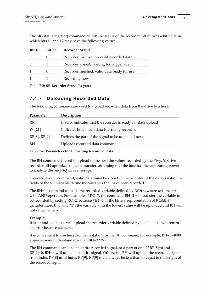
The SR (status register) command details the status of the recorder. SR returns a bit field, in which bits 16 and 17 may have the following values:
Bit 16 Bit 17 Recorder Status
0 0 Recorder inactive, no valid recorded data
0 1 Recorder armed, waiting for trigger event
1 0 Recorder finished, valid data ready for use
1 1 Recording now
Table 7-5: SR Recorder Status Reports
7.4.7 Uploading Recorded Data
The following commands are used to upload recorded data from the drive to a host:
Parameter Description
RR If zero, indicates that the recorder is ready for data upload
WI[21] Indicates how much data is actually recorded
RP[8], RP[9] Defines the part of the signal to be uploaded next
BH Uploads recorded data command
Table 7-6: Parameters for Uploading Recorded Data
The BH command is used to upload to the host the values recorded by the SimplIQ drive recorder. BH optimizes the data transfer, assuming that the host has the computing power to analyze the SimplIQ drive message.
To execute a BH command, valid data must be stored in the recorder. If the data is valid, the fields of the RC variable define the variables that have been recorded.
The BH=n command uploads the recorded variable defined by RC&n, where & is the bit-wise AND operator. For example, if RC=7, the command BH=2 will transfer the variable to be recorded by setting RC=2, because 7&2=2. If the binary representation of RC&BH includes more than one “1”, the variable with the lowest value will be uploaded and BH will not return an error.
Example: If RC=7 and BH=3, BH will upload the recorder variable defined by RC=2. BH=16 will return an error because BH&RC=0.
It is convenient to use hexadecimal notation for the BH command; for example, BH=0x4000 appears more understandable than BH=32768.
The BH command can load an entire recorded signal, or a part of one. If RP[8]=0 and RP[9]=0, BH=n will upload an entire signal. Otherwise, BH will upload the recorded signal from index RP[8] until index RP[9]. RP[9] must always be less than or equal to the length of the recorded signal.
SimplIQ Software Manual Development Aids MAN-SIMSW (Ver. 1.1)
7-12

The data is uploaded in hexadecimal form in order to minimize transmission time (relative to ASCII formatted text), while adhering to the ASCII nature of transmissions. Each data byte is parsed into two nibbles, and the ASCII code of the nibbles is sent from the controller to the host. For example, the short integer number 43794 has the hexadecimal representation AB12. It will be transmitted as “A” “B” “1” “2” with the most significant nibble first and the least significant nibble last. The long integer number 1 will be sent as: “0” “0” “0” “0” “0” “0” “0” “1”.
In order to analyze the BH record, it is important to understand that the internal representation of quantities in the controller is not in user units. For example, while the user relates to motor current in amperes, the controller represents current internally by the bits of the A/D that measures the current. The BH record uploaded recorded currents (and other variables as well) in their internal representation units, and also provides the scaling multiplier to relate it to user units. This way, no multiplication inaccuracies are introduced to the BH records, and the CPU load is minimized.
The recorded transmitted by the controller in response to a BH=n command is described in the following table. The record includes 20 bytes of overhead, and numerical record data. The variables in the table are translated into ASCII as described previously.
Byte Number
Description
Value
Type
0 - 1 Variable type for user. Field has no practical significance.
0: Integer system parameter 1: Real system parameter 2: Integer user program variable 3: Real user program variable
Byte
2 - 3 Data width: number of hex character of single transmitted data item.
4: Short integer 8: Long integer
Byte
4 - 7 Data length: actual number of transmitted data items.
Word
8 - 11 Variable time multiplier: number by which TS must be multiplied to obtain basic recording period.
Depends on RP[0] value Word
12 - 19 Floating number factor, by which every uploaded data item is multiplied in order to convert it to user units, such as amperes, or counts/second.
32-bit float number in IEEE format.
20 - 20+ (Data length) * (Data width) -1: data items. Oldest record is transmitted first, and most recent record is transmitted last.
Words or long integers, according to data width.
Table 7-7: BH Record Structure
SimplIQ Software Manual Development Aids MAN-SIMSW (Ver. 1.1)
7-13

BH record transmission time can be quite long. A record of 2000 long numbers is approximately 8000 bytes, which take at least 4 second to transmit over RS-232 at a baud rate of 19,200. During this time:
The user program continues to run normally.
CAN commands are accepted and processed normally.
RS-232 commands are accepted and executed normally, although the transmission of the response to them is deferred until after the BH upload is complete.
Example: A BH command may return the string: 0008000100013f80000000010000
This string is decomposed to a field as follows: 00 (int) 08 8 bytes per data item in the message 0001 Only one data item in message, after the 20-byte overhead 0001 Record taken every TS 3f800000 To scale, multiply result by 1.0. The floating point IEEE representation of 1.0 is 0x3f800000. 00010000 First data item: 0x10000 = 65536
7.5 Debugging Commands for Database Failures
If the motor cannot start due to a database failure (error EC=54), there is evidently a conflict of parameters, even though each parameter value may be within the permitted range. In order to determine what has occurred, type CD to display a complete report of the CPU and database status, including the parameter that has caused the conflict.
SimplIQ Software Manual Development Aids MAN-SIMSW (Ver. 1.1)
7-14

Chapter 8: Commutation
8.1 General Description
The SimplIQ drives’ fixed magnet motors, in which a winding creates a magnetic field. If the fixed magnet is directed along the field lines of the winding, it is in its steady state, and the winding exerts no force on the magnet. If the magnet is not aligned along the winding field lines, it will attempt to align with them.
Mathematically: T = KeI * cos (θ) where: θ is the angle between the magnet and the field of the winding. Ke is a parameter, proportional to the strength of the magnet. T is the motor winding torque. I is the motor current.
If the magnet is allowed to move, it will rotate until it is aligned with the winding field, and will remain stationary there.
A motor is composed of a fixed magnet and several windings arranged so that each winding generates a field of different direction. By powering the windings alternately, the direction of the winding field moves, and so does the direction to which the rotor is attracted. This process of alternating the powered winding is called commutation.
DC brush motors are equipped with a mechanical device that selects which winding to power. In brushless motors, this selection mechanism is electronic. The “commutation policy” has two major types: stepper and BLDC (Brushless DC).
Commutation parameters are normally set using the Composer Wizard application. To tune commutation manually, thoroughly read the CA[N] documentation in the SimplIQ Command Reference Manual.
8.1.1 DC Brush Motors
Each SimplIQ drive has three motor output connections, although a DC motor has only two wires. In order to drive a DC motor with a servo drive, the motor is connected to the B and C motor phase outputs and the phase A connection is left open.
The following parameters are set next:
CA[28] is set to 1 for a DC motor.
CA[18], encoder reference, is set for reference only. The CA[18] value does not affect anything else at a later time.
CA[16], encoder direction, is set to 0 or 1 so that the encoder will count forward in the desired direction of movement.
SimplIQ Software Manual MAN-SIMSW (Ver. 1.1)
8-1

CA[25], motor direction is set to 0 or 1 so that the motor will rotate in the desired direction for positive torque commands.
The values of CA[16] and CA[25] must be coordinated; otherwise, the feedback direction will be incorrect and the encoder will count negative displacement for positive torques. In addition, the motor will immediately “run away” as soon as speed or position control is attempted.
If you intend to use the SimplIQ drive with DC motors, the rest of this chapter is irrelevant.
8.1.2 Stepper Commutation
With stepper commutation, the windings field is set to point at the desired rotor position. The commutating device need not be informed where the rotor is; it simply assumes that the rotor will come to rest at the field position.
Stepper commutation is simple and reliable. Its main drawback is that normally, |θ| << 90º; therefore, large currents are required to generate a given torque. In its steady state, the motor torque is zero and not affected by motor current. The sensitivity of motor torque to deviation of the rotor angle is maximal. The great sensitivity of the torque to rotor angle generates a fast, but oscillatory position feedback.
8.1.3 BLDC Commutation
With stepper commutation, the windings field is set to point 90º away from the rotor position and the commutating device must know where the rotor is in order to maintain this field direction.
The advantage of BLDC commutation is its maximum torque per given motor current, and its smooth, controllable torque. It is ideal for servo applications. BLDC involves a considerable amount of real-time calculation and requires a rotor position sensor, which decreases motor reliability. The torque is not sensitive to rotor angle.
8.2 Mechanical and Electrical Motion
Most brushless motors have two or three phases (coils, or windings). The SimplIQ drive is applicable for three-phased motors only, called A, B and C.
When the rotor travels, the coils of the three-phased motor are powered in the sequence A-B-C-A-B-C . . . and so on. The powered phases generate a magnetic field, which attracts the permanent magnet of the moving part (rotor). When the phases are powered sequentially, the magnetic field moves and the rotor follows continuously. When the rotor passes from a location over the A coil to the next A coil, it covers an electrical cycle.
Several coil sets — with corresponding fixed-magnet pole pairs on the rotor — may be located around a motor circumference. For example, a motor with three pole pairs complete three electrical cycles in one mechanical shaft revolution.
SimplIQ Software Manual Commutation MAN-SIMSW (Ver. 1.1)
8-2

You can read the electrical and mechanical angle of the motor using the following commands:
Command Description
WS[20] Stator field angle, in 1024 counts/revolution units. Stator field angle (degrees) = WS[20] x (360/1024).
WS[21] Commutation counter. WS[21] counts the main high-resolution position sensor, modulo CA[18].
8.3 Commutation Sensors
For BLDC commutation, rotor position sensors are required. Commutation sensors can be categorized into two main groups:
Direct field sensors that sense the magnetic field of the motor
Shaft position sensors
8.3.1 Rotor Magnetic Field Sensors
This first group of sensors consists mainly of digital Hall sensors, which may be used for commutation with minimum calculation, because they reflect the direction of the rotor with direct respect to the windings. However, digital Hall sensors provide only rough information. Standard digital Hall sensors divide the electrical period of the motor into six units, as illustrated in the following figure.
Hall A
Hall B
HallC
270deg
330deg
30deg
90deg
150deg
210deg
270deg
Figure 8-1: Digital Hall Sensor Readout
SimplIQ Software Manual Commutation MAN-SIMSW (Ver. 1.1)
8-3

The following table describes the digital Hall sensor reading. The BLDC field angle is the angle that produces maximum torque for this Hall sensor reading.
Hall A
Hall B
Hall C
Electrical Rotor Position (Degrees)
BLDC Field Angle (Degrees)
0 0 0 Illegal
1 0 0 330 - 30 90
1 1 0 30 - 90 150
0 1 0 90 - 150 210
0 1 1 150 - 210 270
0 0 1 210 - 270 330
1 0 1 270 - 330 30
1 1 1 Illegal
The crude division into six draws a rough torque from the motor, and requires hard switching of the motor winding currents.
In many application digital Hall sensors are used together with higher-resolution position sensors. The Hall sensors serve to initialize the field direction and add redundant position sensing for increased reliability.
8.3.2 Shaft Angle Sensors
The second group of sensors consists of shaft angle sensors. This category includes encoders of all types (incremental digital and analog, absolute digital and analog), resolvers, capacitive sensors and others. The SimplIQ drive can only interface directly with digital and analog incremental encoders. Shaft angle sensors normally have good resolution, but must be homed (referenced absolutely) with respect to the rotor electrical angle.
For commutation calculation, it is important to now how many bits the shaft sensor counts per single electrical cycle. If this number is not an integer, after a certain amount of movement, the calculated commutation angle may accumulate numerical errors and cause the motor to lose torque. The numerical commutation error is not a serious issue with linear motors, because the limited travel also limits the commutation calculation error. With rotary motors, each mechanical shaft rotation involves an integer number of encoder counts, per an integer number of electrical cycles. This means that the commutation can be kept as accurate as: p1 = mod (encoder, counts per shaft revolution)
and
Electrical rotor angle = 360º * * mod (pl, ) Counts per shaft revolution
Number of pole pairs Counts per shaft revolution Number of pole pairs
SimplIQ Software Manual Commutation MAN-SIMSW (Ver. 1.1)
8-4

8.3.3 Combining Sensor Types
8.3.3.1 Initializing Encoder-based Commutation
When starting a motor, the electrical angle can be roughly estimated from the digital Hall sensors, which usually read the electrical angle to +30 electrical degrees. The exception is that instant at which the Hall sensor reading switches; at this point, the Hall sensors read the electrical angle accurately. After the first Hall sensor switch, accurate commutation is maintained by updating the commutation counter incrementally using the shaft position sensor.
8.3.3.2 Detecting Commutation Errors (Loss of Feedback)
After encoder commutation begins, two sources of electrical angle measurement are available: the high-resolution measurement by the encoder, and the low-resolution — but reliable — digital Hall sensor readout.
The digital Hall sensor readout defines a range in which the high-resolution calculated angle should reside. Deviating from this range by more than a few degrees results in a commutation error and automatic motor shutdown.
The allowed deviation is increased at higher speeds, because then the sensor and the calculation delays contribute a significant matching error.
The most common causes for commutation loss are:
A slit in the encoder disk is clogged with direct. When this happens, an encoder of 4000 counts/revolution may count, for example, 3999 counts/revolution. After a number of revolutions, the cumulative error grows to a large number.
Too fast a speed relative to the defined encoder filter (EF[1] and EF[2] commands), and encoder pulses are lost.
An interpolator derives the encoder A/B pulses. Certain interpolators intermittently send pulse batches of much higher frequency than the motor speed. Encoder filters should not be used with interpolators, even if the motor speed is supposed to be slow.
8.3.4 Parameterization of Commutation and Commutation Errors
8.3.4.1 Winding Order
The SimplIQ drive has three motor connection pins: A, B and C. The pin names are not rigidly assigned an actual role: The SimplIQ drive can internally define which motor phase is connected to which output pin. The CA[25] parameter controls this connection, as follows:
CA[25]
Phase A Connected to Pin:
Phase B Connected to Pin:
Phase C Connected to Pin:
0 A B C
1 A C B
Table 8-1: Motor Connection Pin Parameters
SimplIQ Software Manual Commutation MAN-SIMSW (Ver. 1.1)
8-5
As shown in the table, change CA[25] switches the B and C phases. Actually, changinge CA[25] will reverse the direction in which the motor moves for a given torque command.
8.3.4.2 Hall Sensor Parameterization
Figure 8-1 presents an idealized picture of the digital Hall sensor reading. All waveforms are in the precise phase and polarity. In practice, the results of the figure may not equal what is seen immediately after connecting the motor and its sensors to the SimplIQ drive.
The Hall sensors must be matched to the motor coils. The connection order of the Hall sensors to their respective connectors pins may be incorrect, or the motor phase connections may have been switched (as described in the previous section) to modify the motor direction.
The Hall sensors may be active high or active low. For certain Hall sensor arrangements (known as 30º arrangements), two sensors may be active high and the other one active low, or vice versa.
In addition, the switching lines in the figure are set at 30, 90, 150, 210, 270 and 330 degrees. The even spacing of 60º is true for most motors, but many motors exhibit a significant origin deviation. For example, with a 10º deviation, the digital Hall sensor switching points may be at 40, 100, 160, 200, 280 and 340 degrees respectively. This error, although hardly noticeable at low speed, causes the loss of significant motor torque at high speed.
If Hall sensors are not present, and if commutation is performed using an incremental encoder, then upon starting the motor, the SimplIQ drive must first find the electrical direction of the motor. If digital Hall sensors are not present (CA[20]=0), then at motor on, a commutation search is performed (refer to section 8.4).
The following parameters describe the Hall sensors:
Parameter Description
CA[1] Polarity of digital Hall sensor A: 1 for active high; 0 for active low.
CA[2] Polarity of digital Hall sensor B: 1 for active high; 0 for active low.
CA[3] Polarity of digital Hall sensor C: 1 for active high; 0 for active low.
CA[4] Actual Hall sensor connected to A Hall connector pin: 1 for A, 2 for B and 3 for C.
CA[5] Actual Hall sensor connected to B Hall connector pin: 1 for A, 2 for B and 3 for C.
CA[6] Actual Hall sensor connected to C Hall connector pin: 1 for A, 2 for B and 3 for C.
CA[7] Offset of digital Hall sensors in encoder units. The range for this parameter is [0…CA[18]-1]. This parameter compensates for deviations in the Hall sensor switching point. If no encoder is present, set this parameter to zero.
CA[20] Digital Hall sensors present: 0: No digital Hall sensors connected 1: for Digital Hall sensors connected.
Table 8-2: Hall Sensor Parameters
SimplIQ Software Manual Commutation MAN-SIMSW (Ver. 1.1)
8-6

8.3.4.3 Encoder Parameterization
Accurate commutation requires a high-resolution sensor. Many types of high-resolution sensors exist. For the SimplIQ drive, the following selections are available:
Parameter Description
CA[17] Commutation sensor type: 1 for Main encoder.
CA[21] Position sensor present: 0: No high-resolution commutation sensor. Commutation will be based on digital Hall sensors only. 1: Main position sensor will be used for commutation.
The encoder is normally used both for motion feedback and for commutation. As a motion feedback counter, it must count up when the motor goes forward, in the application sense. As a commutation counter, it must count up when the commutation angle increases. These two requirements are not necessarily the same, so the following two parameters are needed:
Parameter Description
CA[16] Encoder direction: Set 0 or 1 so that the encoder will count forward in the desired movement direction.
CA[25] Motor direction: Set 0 or 1 so that with positive torque, the motor will rotate in the direction for which the encoder counts up.
The encoder measures the shaft angle. In order to commutate, the encoder count per electrical revolution is needed. Normally, the number of encoder counts per motor revolution is an integer (if not, commutation with an encoder may be incorrect). The number of pole pairs per revolution is always an integer. By knowing the encoder counts per mechanical revolution, along with how many pole pairs are in a revolution, the commutation counter can infinitely update without accumulate errors.
For linear motors, the number of pole pairs CA[19] should be set to the largest number of full electrical cycles possible for that motor. Enter the “encoder counts in revolution” CA[18] parameter as the number of encoder counts for CA[19] electrical cycles.
The following table lists the encoder parameters:
Parameter Description
CA[18] Encoder bits per revolution, after resolution multiplication by 4, in the range [6…224=16,777,216]. For an incremental encoder with 1000 lines, CA[18] will be 4000.
CA[19] Number of motor pole pairs: [1…50].
CA[23] Counts per meter (an positive integer): 0: Rotary motor 1: Counts per meter in linear motor This parameter is not used directly by the drive; it is just stored there for the convenience of the host.
Table 8-3: Encoder Parameters
SimplIQ Software Manual Commutation MAN-SIMSW (Ver. 1.1)
8-7

8.4 Auto-phasing and Commutation Search
When starting the motor, the rotor can be located anywhere. The torque of a brushless DC motor is given by the equation:
)sin(IKT T θ⋅⋅= (1)
rs θ−θ=θ (2) where: T is the motor torque. KT is the motor constant. I is the motor current. θ is the electrical angle between the rotor and the field at the stator. θs is the electrical angle of the stator field. θr is the electrical angle of the rotor.
The angle θs is known because the drive controls it directly. The angle θr is unknown.
If θs is rotated — that is, θs –2πf * t, where f is a frequency and t is the time — the result is the following sinusoidal torque: T = KT * I * sin(2πf * t - θr) (3)
For that torque, the motor shaft will move according to: P(t) = A(f) * KT * I * sin (2πf * t - θr – φ(f)), where: P(t) is the motor shaft position. A(f)ejφ(f) is the transfer function of the motor and its load at the frequency f.
By applying a torque of (3) and measuring the position, both A(f) and rθ can be identified.
8.4.1 Selecting Parameters
The parameters I and f can be selected from the following range:
Parameter Description
I The torque is selected by the parameter CA[26], which defines I as a percentage of the continuous current rating CL[1]. For example, if CA[26] = 50, then I = 0.5 CL[1].
f CA[15] controls the frequency of the sinusoidal motor torque. The basic frequency (with CA[15] = 0) is such that a cycle is completed in 128 * TS microseconds. For a SimplIQ drive with TS=80, this will be a cycle of 10,240 microseconds, which is about 100 Hz. The frequency is 2CA[15] * basic frequency of CA[15] in the range [-4…4]. For example, with CA[15] = 2, the frequency is about 40 Hz, whereas with CA[15] = -2, the frequency is about 640 Hz.
SimplIQ Software Manual Commutation MAN-SIMSW (Ver. 1.1)
8-8

The selection rules for parameters I and f are as follows:
The torque I must be as large as possible so as to reduce the relative effect of disturbance torques (such as cogging and friction) on the resulting waveform. Normally, I is taken as about 50% of the continuous motor current.
The frequency f must be selected so that the amplitude of the position sine is 6 to 8 bits. The motor position can be analyzed accurately enough when the position sine amplitude is 4 encoder bits or more. A slightly higher amplitude is set to prevent minor load changes from disturbing the analysis. Larger position amplitudes will work, but the shaft oscillation at the motor starting process will be unnecessarily large.
The frequency f must be such that in that frequency, the load behaves inertially. This means that in that frequency, the phase angle φ(f) is in the range of [-140…-220] degrees, and that the amplitude function A(f) does not have the high gradient of near resonance regions. The algorithm will not function near a resonant frequency, or in a low frequency in which a large viscous friction is present.
Specifying a very high oscillation frequency (CA[15] = -3 or -4) is not recommended, because not enough position samples will be available for each sine cycle.
The Composer program normally selects the parameters I and f at the “Establishing Commutation” stage of auto-tuning.
8.4.2 Method Limitation
The algorithm presented here is quite robust, and should work for most motor systems, including those with moderate backlash. It does, however, have the following limitations:
The encoder must have a resolution of at least 256 counts per pole pair. For example, if a motor has three pole pairs, 256 lines (1000 counters/revolution) will suffice. An encoder with 128 lines will not.
The system cannot be extremely unbalanced. It is essential that the motor does not accelerate significantly when no current is applied.
The motor cannot be free to oscillate in both directions.
The motor static load should not change significantly. If the static load is subject to considerable changes, tune the algorithm with the highest possible load. Namely, the inertia of the load must be above 40% of its value from when the parameters were tuned, and it cannot exceed 40% of its value from when the parameters were tuned. If the load inertia is too high, the present torque level will not suffice for oscillating the motor shaft. The algorithm will fail and the motor will not start.
The algorithm assumes that in the excitation frequency, the motor and the load behave like inertia. This assumption fails in the following cases:
The excitation frequency is a resonant frequency of the system.
There is a large viscous (speed-dependent) friction and the excitation frequency is so low that the phase of the transfer function between the torque and acceleration is not in the range of [-30…30] degrees. If the transfer function phase is out of range, the algorithm will fail and the motor will not start.
SimplIQ Software Manual Commutation MAN-SIMSW (Ver. 1.1)
8-9

8.4.3 Protections
The method described here can work reliably in many practical situations, although it does not match every application. If the parameters of the method are not tuned properly, or if the method does not match the application, the motor starting process will fail.
After setting MO=1, the algorithm will attempt to rotate the motor back and forth and find the commutation angle. If the results are not reliable, because the oscillation amplitude is too small or because the load behavior is not inertial, MO will reset automatically to zero and the motor will not start.
8.4.4 Maximum Number of Iterations for Auto-phasing
The CA[27] parameter defines the maximum admissible number of iterations for the auto-phasing process. If the process fails due to overload (the motion amplitude is less than CA[24]), the auto-phasing may be repeated several times, doubling the current at each iteration. If the peak current limit is reached during any attempt, the auto-phasing process will stop even if CA[27] allows continuous iterations.
8.4.5 Starting the Motor without Digital Hall Sensors
The following parameters are relevant to starting the motor when digital Hall sensors are not used.
Parameter Description
CA[18] CA[19]
Encoder resolution and number of motor pole pairs. CA[18] must be greater than CA[19] * 256.
CA[20] Must be set to 0 to indicate that no Hall sensors are present.
CA[21] Must be set to 1 to indicate that an encoder is present.
CA[15] Set the oscillation frequency as explained previously.
CA[24] Set the minimum acceptable oscillation amplitude to 4.
CA[26] Set the excitation amplitude as a percentage of the continuous current.
CA[27] Set the maximum number of iterations for the auto-phasing process.
MO MO=1 sets the motor to on. If the motor starts to fail, MO resets to 0.
WS[15] Reads the actual oscillation amplitude.
WS[16] Flag if a non-inertial behavior has been observed.
8.5 Continuous vs. Six-step Commutation
The basic commutation equation for a sinusoidal motor (repeated here for convenience) is: T = KT * I * sin(θF - θr) (1) where: θF is the field electrical angle. θr is the rotor electrical angle.
SimplIQ Software Manual Commutation MAN-SIMSW (Ver. 1.1)
8-10

To optimize the torque, it is necessary to maintain o90rF ≈θ−θ .
The commutation error can be defined as follows: ( )rF90 θ−θ−=εθ
o . Ideally, .0=εθ
The torque production is not very sensitive to εθ. Writing equation (1) as: T = KT * I cos (εθ), it can be seen that a discrepancy of 5° can result in a loss of about 0.4% of the torque. With a miss of 30°, 13.4% of the torque is lost, as illustrated in the following figure:
-100 -50 0 50 1000
20
40
60
80
100
Commutation miss angle, degrees
Lost torque, %
Figure 8-2: Loss of Torque due to Commutation Miss
Two main methods — six-step commutation and continuous commutation — are used to keep εθ near zero.
8.5.1 Six-step Commutation
With six-step commutation, only two motor terminals are energized at each time instance. The third motor phase is open-circuited. Six field angles are possible:
Current flows: Field Direction (degrees)
C → A, B open 30
C → B, A open 90
A → B, C open 150
A → C, B open 210
B → C, A open 270
B → A, C open 330
Table 8-4: Six-step Commutation
SimplIQ Software Manual Commutation MAN-SIMSW (Ver. 1.1)
8-11

Digital Hall sensors have evolved to support six-step commutation.
The crude six steps produce an approximately 13% ripple torque when used with sinusoidal motors, and must less ripple torque when used with trapezoidal motors (refer to section 8.6). The main drawback of six-step commutation is the need to abruptly switch phase currents, which imposes an extreme bandwidth demand on the current controller. If the bandwidth of the current controller is less than satisfactory, noticeable “knocks” will occur at commutation switching points.
implIQ drives use six-step commutation if no commutation encoder is available (CD[21]=0). In such a case, the Hall effect sensors are also used as position sensors for speed and position control.
SimplIQ drives also use six-step commutation immediately after motor on, and before the first Hall sensor transition is encountered. Afterwards, the high-resolution commutation sensor (encoder) can be homed, and commutation may proceed in the continuous mode.
8.5.2 Continuous Commutation
With continuous commutation, all three motor coils are powered simultaneously to yield a magnetic field exactly in the direction of the rotor. This continuously brings εθ near zero . with minimal torque losses and ripple torques.
The continuous commutation mode is native to the SimplIQ drive and is used most of the time. This mode of commutation is much more complex than the six-step commutation. In fact, it requires two independent current controllers for controlling both the amplitude and the direction of the windings magnetic field.
Continuous commutation reduces the dynamic demands from the current controller, because such demands are rarely switched abruptly.
8.6 Winding Shapes
For a general motor, the following algorithm applies: ))240(hI)120(hI)(hI(KT bba
oo −θ+−θ+θ⋅= where: T is torque. K is a constant. h is the windings shape function. Ia, Ib and Ic are the A, B and C phase currents, respectively.
For optimal efficiency, the phase currents must be: )240(hII),120(hII),(hII 0c0b0a
oo −θ=−θ=θ= for some value I0. (1)
In other words, the phase currents must be proportional to the corresponding commutation function values. If (1) is satisfied, the magnetic field produced by the winding currents is perpendicular to the rotor magnet.
SimplIQ Software Manual Commutation MAN-SIMSW (Ver. 1.1)
8-12

Most motors are wound to sinusoidal or trapezoidal winding forms, but no motor can be exactly sinusoidal or trapezoidal. Trapezoidal motors are normally chosen for six-step commutation, whereas sinusoidal motors are normally chosen for continuous commutation.
Figure 8-3: Winding Shape Function for Trapezoidal Motor
Figure 8-4: Winding Shape Function for Sinusoidal Motor
In order to optimize the SimplIQ drive for as many motors as possible, the SimplIQ drive can be programmed to any winding shape function. SimplIQ drives come from the factory programmed, by default, for sinusoidal motors, but the motor waveform can be changed using the Composer program.
0 50 100 150 200 250 300 350 400-0.4
-0.3
-0.2
-0.1
0
0.1
0.2
0.3
0.4
Theta (degrees)
h(th
eta)
0 50 100 150 200 250 300 350 400-0.8
-0.6
-0.4
-0.2
0
0.2
0.4
0.6
0.8
h(th
eta)
Theta (degrees)
SimplIQ Software Manual Commutation MAN-SIMSW (Ver. 1.1)
8-13

8.7 Loading the Commutation Table
The commutation table can be programmed using the HV command. The HV command syntax is non-standard. For a detailed description of commutation table load, refer to the HV command section in the SimplIQ Command Reference Manual.
SimplIQ Software Manual Commutation MAN-SIMSW (Ver. 1.1)
8-14

Chapter 9: The Current Controller
This chapter describes the current controller and its parameterization. Also included are a description of the current limiting process and the drive protections.
The commands relevant to the current controller are:
Command Description
TS Current controller sampling time
KP[1] Proportional gain of current controller (nominal voltage)
HI[1] Integral gain of current controller (nominal voltage)
XP[4] Time constant for DC power bus filter
XP[5] Step limiter for torque command filter
XP[6] Time constant for torque command filter
MC Largest available drive current
PL[1] Application peak current limit
PL[2] Duration for peak current limit
CL[1] Continuous application current limit
Each of these commands is described fully in the SimplIQ Command Reference Manual.
This chapter deals with currents measured in amperes. The definition of ampere used for three-phased motor current is explained in section 2.3of this manual.
SimplIQ drives energize all three motor terminals simultaneously. This means that it must control two current components simultaneously, because the phase currents are linearly dependent (the sum of all phase currents is zero). The SimplIQ drive’s vector current controller directly controls the following two current components:
IQ: current component that produces a magnetic field in the desired direction (normally perpendicular to the rotor fixed magnet field)
ID: current component that produces a magnetic field orthogonal to the desired direction (normally parallel to the rotor fixed magnet field)
The following diagram describes the structure of the current controller:
SimplIQ Software Manual MAN-SIMSW (Ver. 1.1)
9-1

Pre-filterTorquecommand
QP+I controller
OutputCoordinatetransform
DP+I controller
Power bridge& motor
InputCoordinatetransform
Va
Vb
Vc
Ia
Ib
Ic
PW M output
Current sensors
-Σ
IQ
ID
Σ-
0 Commutationangle θ
VQ
VD
Peak/Continuous lim itsaturation
Figure 9-1: Current Controller Structure
The input coordinate transform retrieves the IQ and ID (active and reactive) components of the motor current.
)240(hI)120(hI)(hIIQ cbaoo +θ++θ+θ=
and )330(hI)210(hI)90(hIID cba
ooo +θ++θ++θ= where: θ is the commutation angle.
)(h θ is the input winding function.
The output coordinate transform predicts the variation of the phase voltages during the motor rotation:
)90(gV)(gVVA DQo+θ+θ=
)210(gV)120(gVVB DQoo +θ++θ=
)330(gV)240(gVVC DQoo +θ++θ=
where )(g θ is the output winding function.
For sinusoidal motors, )cos()(h θ≡θ and )cos()(g θ≡θ . The SimplIQ drive tabulates both )(h θ and )(g θ .
9.1 Current Limiting
The maximum phase current of the SimplIQ drive is given by the parameter MC, which describes the hardware of the power stage and cannot be modified. The peak current limit for a given application is programmed to the parameter PL[1] amperes (see section 2.3 in this manual).
You should program PL[1] to be smaller than MC if you do not wish to utilize the full power of the drive; this may be the case if the drive is oversized with respect to your application or because the line voltage is not enough to drive MC amperes into the motor.
SimplIQ Software Manual The Current Controller MAN-SIMSW (Ver. 1.1)
9-2

Do not specify M
BR
V]1[PL >
where: VB is the DC motor supply voltage. RM is the motor resistance.
You should define a PL[1] small enough so that at peak current there is enough voltage to drive current changes. Otherwise, at large currents, the drive speed of response will be limited by voltage saturation.
The continuous current limit for your application is programmed by CL[1]. This parameter cannot exceed MC/2, because greater continuous currents could cause drive overheating.
To avoid motor overheating, you can set CL[1] < MC/2.
As a recommendation, you should select PL[1] and CL[1] to be as great as the drive and application permit. This will extend the linear range of the drive to its maximum and thereby optimize the servo parameters.
The parameters PL[1] and CL[1] specify limits for the current demand. At transients, the motor current may exceed PL[1] and CL[1] due to overshooting.
The decision to limit the motor current demand to CL[1] or to PL[1] is made by the drive in real time. The LC flag reports the current limiting status. The decision mechanism is depicted as follows:
-
Ic
Ib
Ia
RMS
2c
2b
2a III ++
If RMS > THOLD, thenLIMIT=CL[1]THOLD=0.9CL[1]LC=1
elseLIMIT=PL[1]THOLD=CL[1]LC=0
THOLD
LIMIT (CL[1] or PL[1])
RMS
Low Pass filter
Filtered RMS current
LC
Figure 9-2: Peak/Continuous Current Limit Selection
When the current limit switches, the comparison threshold (named THOLD in Figure 9-2), changes slightly. This hysteresis prevents frequent switching of the current limit.
SimplIQ Software Manual The Current Controller MAN-SIMSW (Ver. 1.1)
9-3

Slower time constants in the low-pass filter permit a peak current demand for longer times, but also take more time to recover from a limitation to CL[1]. The time constant τ of the low-pass filter is selected by PL[2] as follows:
⎥⎦⎤
⎢⎣⎡ −
−=
MCCL
PL]1[1log
]2[τ
With this selection, when PL[2] is set to MC, and after the current demand has been zero for a long time, the drive will permit a maximum of PL[2] seconds of peak current, and then switch to continuous current limiting.
For other settings of PL[1], the maximum time for which the peak current can be maintained, after the current demand has been zero for a long time is:
- τ⋅⎥⎦
⎤⎢⎣
⎡−
]1[]1[1log
PLCL
seconds
The programming range for PL[2] is very limited. In most applications, it is recommended that PL[2] be left at its factory default of 3 seconds.
Example: The following graph illustrates the signals related to the current command limiting process for MC=6, PL[1]=6, PL[2] = 3 and CL[1] =3. The motor current demand increases from zero to 6 amperes at the time of 0, and is then decreased to 0 at the time of 5 seconds. The state of the low-pass filter increases until it reaches the continuous current limit of 3 at the time of 3 seconds. Then, the LC flag is raised and the motor current command is decreased to CL[1] = 3 amperes. After the motor current command is set to zero, the state of the filter begins to drop. When it reaches 2.7 amperes = 90% of 3 amperes, the LC flag is reset and the torque command limit once again becomes 6 amperes.
0 1 2 3 4 5 6 7 8 90
1
2
3
4
5
6
Application current demand motor currentcommand
F ilter state
LC current limitIndication
Figure 9-3: Current Command Limiting Example
SimplIQ Software Manual The Current Controller MAN-SIMSW (Ver. 1.1)
9-4

9.2 The PI Current Controller
The controllers for the IQ and ID components are similar, as depicted in the following block diagram:
Kp[1]/VB
KI[1]/VB
-Σ
Feedback
Command
∑ εk
k
ε
Integrator
Proportional gain
Integral gain
Saturation
Σ
Anti wind up
Output
Bus voltageVB
Bus Voltage Filter
Figure 9-4: Current PI Controller
The following table lists the roles of the inputs and outputs in the IQ and ID controllers:
Parameter Q Controller D Controller
Bus voltage Measured and filtered motor power DC voltage
Command Torque command 0
Feedback IQ ID
Output VQ VD
Table 9-1: IQ and ID Controller Parameters
Saturation is given by: 0.5 TS/25 * 10-3
where: TS is the current controller sampling time, in microseconds. 25 * 10-3 is the period of the 40-MHz PWM generator clock, in microseconds.
The proportional and integral gains are divided by the DC voltage because the output of the current controller is the PWM duty cycle.
The PWM duty cycle sets the corresponding motor terminal voltage to: Motor terminal voltage = (PWM duty cycle) x (DC power voltage). This equation shows that the uncertainty in the DC power voltage acts as a gain uncertainty for the current controller.
SimplIQ Software Manual The Current Controller MAN-SIMSW (Ver. 1.1)
9-5

The DC power voltage varies significantly: It decreases at high current due to the power supply output impedance and increases when, upon braking, the motor acts as a generator. The division of the bus voltage makes the output of the controller proportional to the physical motor voltage, eliminating the uncertainty.
The bus voltage is filtered to avoid too rapid changes in current loop PI parameters. The bus voltage filter is a simple low-pass filter, with a bandwidth of:
32768]4[XPlog
TS8106
⋅π−
Hz.
The relation between XP[4] and the time constant of the filter is calculated in the table below for several values of XP[4] and TS=50.
XP[4] Bus Voltage Filter Bandwidth, in Hz
31,750 25 Hz (high impedance supply)
30,720 (factory setting) 50 Hz
28,900 100 Hz (low impedance, high-ripple supply)
Table 9-2: Bandwidth Selections for Bus Voltage Filter
XP[4] is factor set to 30,720. Set it to a higher value if the output impedance of your power supply is too high, causing an interplay between the filter gains and the DC motor voltage. Set it to a lower value if you have a very low-impedance power supply, but a high ripple voltage. In normal applications, it is recommended not to change the factor setting of XP[4].
9.3 Current Amplifier Protections
The current amplifier and the power stage have several protections, each of which, when activated, immediately shuts down the drive. If brake action is defined (by the OL[N] and BP[N] commands; refer to the SimplIQ Command Reference Manual), the brake is immediately activated, and in the next 10 milliseconds, the drive will not turn on the motor, even if instructed to do so.
To determine if the drive has been shut down by a protection:
Observe the Motor On and Fault bits in the SR report, or in the CAN special status object.
Map the Motor Fault event to an event-drive CAN PDO.
Poll the MO variable (which drops to 0 on exception).
Poll the MF variable (which reports a non-zero value after an exception has been trapped).
Map a digital output to AOK (refer to the OL command).
You may install an AUTO_ERR routine in your user program to automatically respond to an exception shutdown.
SimplIQ Software Manual The Current Controller MAN-SIMSW (Ver. 1.1)
9-6

The protections that are provided are:
Protection
MF Reports
Reason
Over-voltage 0x5000 Voltage of the power supply is too high, or the servo drive failed to absorb kinetic energy while braking a load. A shunt resistor may be required. The over-voltage threshold differs with the power stage model (refer to product user manual). A probable reason for this protection is an attempt to decelerate a motor that is moving so fast that the drive fails to absorb the motor’s kinetic energy. The solution to this is to decelerate more slowly or to add a shunt resistor to the power supply.
Under-voltage 0x3000 The power supply has been shut down or its impedance is too high. The under-voltage threshold differs with power stage models; refer to the product user manual. A probable reason is that PL[1] and CL[1] have been set too high for the power supply.
Short circuit 0xb000 A large, fast current pulse has been detected. The motor or its wiring may be defective or the drive may be faulty.
Over-temperature 0xd000 The power stage of the drive is too hot. An additional heatsink or forced cooling is required.
Over-current 0x8 An unexpected, large current has exceeded 1.15 * MC. The current loop or the winding shape function HV[N] may need better tuning.
Table 9-3: Current Amplifier and Power Stage Protections
SimplIQ Software Manual The Current Controller MAN-SIMSW (Ver. 1.1)
9-7
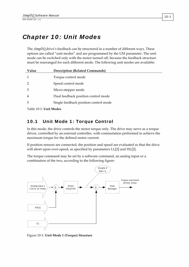
Chapter 10: Unit Modes
The SimplIQ drive’s feedback can be structured in a number of different ways. These options are called “unit modes” and are programmed by the UM parameter. The unit mode can be switched only with the motor turned off, because the feedback structure must be rearranged for each different mode. The following unit modes are available:
Value Description (Related Commands)
1 Torque control mode
2 Speed control mode
3 Micro-stepper mode
4 Dual feedback position control mode
5 Single feedback position control mode
Table 10-1: Unit Modes
10.1 Unit Mode 1: Torque Control
In this mode, the drive controls the motor torque only. The drive may serve as a torque driver, controlled by an external controller, with commutation performed to achieve the maximum torque for the defined motor current.
If position sensors are connected, the position and speed are evaluated so that the drive will abort upon over-speed, as specified by parameters LL[2] and HL[2].
The torque command may be set by a software command, an analog input or a combination of the two, according to the following figure:
TC
Analog input 1(-10 to 10 Volts)
AG[1]Amp/Volt Σ
Enable ifRM==1
Torque command(DV[1], Amp)
Σ
AS[1]
`
-
StopManager
Figure 10-1: Unit Mode 1 (Torque) Structure
SimplIQ Software Manual MAN-SIMSW (Ver. 1.1)
10-1

The AS[1] parameter compensates for possible offsets in the driving equipment and internally in the SimplIQ drive. If you do not use the analog input for the torque command, set AG[1] = 0 or RM = 0 in order to avoid the noises and offset that affect the drive torque command.
The combined (software and analog input) current demand is reported by DV[1].
The Stop Manager does the following:
If hard stop is active, sets the torque command to zero
If RLS is active, clips negative torque commands to zero
If FLS is active, clips positive torque commands to zero
The Stop Manager does not affect the reference generator: When the relevant switch is released, the torque command value set by the reference generator is restored.
10.2 Unit Mode 2: Speed Control
In this mode, the drive controls the motor speed by feedback. The speed controller demands torque from the current controller.
The reference to the speed controller is a sum of software commands and an auxiliary speed command that is derived using the analog input, the auxiliary encoder input and the ECAM table (details in Table 10-2).
The Stop digital input and the limit switches (RLS, FLS) can be used to stop or to limit the direction of the motor (described in section 10.2.3). The drive will abort upon over-speed, as specified by the parameters LL[2] and HL[2]. The speed control scheme can be depicted as follows:
Software speedcommand
Σ
Enable ifRM==1
Speed command(DV[2], cnt/sec)
Σ
Software speedfeedback
-
Torque command(DV[1], Amp)Auxiliary speed
commandStop
manager
Stop and limitswitches
Smoother
Speedcontroller
DV[4]
DV[5]
Figure 10-2: Unit Mode 2 (Speed) Structure
SimplIQ Software Manual Unit Modes MAN-SIMSW (Ver. 1.1)
10-2

If you do not use the analog input for the torque command, set RM = 0, in order to avoid noises and offset that affect the drive speed command. The DV[2] command reports the combined (software and analog input) speed demand, after being further processed for acceleration and speed limiting, and for the switch actions RLS, FLS and STOP.
DV[4] and DV[5] retrieve the external and software components of DV[2], respectively.
10.2.1 Software Speed Command
The software speed command generator generates speed commands, subject to acceleration, deceleration and speed limits. The following commands are relevant to the generation of the software speed command:
Command Description
AC Profiler acceleration limit, in counts/second2.
BG Begin command.
DC Profiler deceleration limit, in counts/second2.
JV Profiler final speed command, in counts/second.
PM PM=1: Normal acceleration limits form software speed command. PM=0: AC and DC are ignored and SD is used instead. The Composer setup program uses this mode when tuning the speed controller. During regular operation, PM=1 is recommended.
SF Smooth factor: time, in milliseconds, required to develop the full acceleration of AC and deceleration of DC.
VH[2] Maximum speed command, in counts/second.
VL[2] Minimum speed command (bound by speed command, negative value), in counts/second.
HL[2] Maximum allowed speed, in counts/second. If feedback indicates a higher value, the motion is automatically aborted.
LL[2] Minimum allowed speed, in counts/second. If feedback indicates a lower value (high value in negative direction), motion is automatically aborted.
IL[N] Map functions to digital inputs, which may function as hardware ST or BG instructions.
Table 10-2: Software Speed Commands
The BG command enters a new desired speed value together with the acceleration and deceleration limits. The AC acceleration is used to increase the absolute speed value, while the DC deceleration is used to decrease the absolute speed value.
The algorithm of the acceleration-limited software speed command is as follows:
SimplIQ Software Manual Unit Modes MAN-SIMSW (Ver. 1.1)
10-3

1. Has any new BG command been accepted by the software or hardware? If yes, update the speed target to the value of JV, and also update the permitted acceleration and deceleration to the values of AC and DC.
2. If the speed target and speed command are positive, and the speed target is greater than the speed command, select AC for the acceleration limit. If the speed target and speed command are negative, and the speed target is less than the speed command, also select AC. Otherwise, select DC for the acceleration limit.
3. Advance the speed command towards the speed target as much as the selected acceleration/deceleration permits. In a trivial case, in which the speed command already equals the speed target, do nothing.
The acceleration-limited software speed command is fed to a smoothing filter, which limits the rate of development towards the full acceleration or deceleration.
Example 1: In order to demonstrate the concepts of target speed and the speed command — along with AC and DC acceleration/deceleration limits — let: MO=1; JV=4000; AC=100,000; DC=200,000; SD=106; PM=1; RM=0; SF=0; BG; The following figure depicts how the speed command to the controller (DV[2]) tracks the target speed specified by changing the JV parameter, followed by a BG.
0 0.01 0.02 0.03 0.04 0.05 0.06 0.07 0.08-1000
-500
0
500
1000JV DV[2]
AC DC
AC
Figure 10-3: Speed Profiling Using JV, AC and DC
The speed reference to the controller may be changed any time, regardless of the state of the profiler. In the previous figure, the required speed was changed at time 0.065, from -1000 to 0, before reaching the speed command of -1000.
SimplIQ Software Manual Unit Modes MAN-SIMSW (Ver. 1.1)
10-4

Example 2: This example demonstrates the smoothing filter and the smoothing factor SF: MO=1; JV=4000; AC=100,000; DC=100,000; SD=1000000; PM=1; RM=0;BG SF has three different values:
The SF=0 graph displays sharp corners, because smoothing is ignored, thereby allowing non-continuity of acceleration.
The SF=10 graph takes 10 milliseconds more to stabilize the speed software command; however, the speed reference profile is much smoother.
For the SF=50 graph, the smoothing is so strong with respect to total acceleration time that the AC acceleration is never reached.
0 0.02 0.04 0.06 0.08 0.10
500
1000
1500
2000
2500
3000
3500
4000
SF=0 SF=10
SF=50
Time (sec)
Speed reference (count/sec)
Figure 10-4: Speed Command for Different Smooth Factors
The profiler smoothes the motion and decreases (and may also prevent) overshoots, while introducing a delay in the controller response.
10.2.2 The Auxiliary Speed Command
The auxiliary speed reference is generated according to the block diagram that follows. The parameters relevant to auxiliary speed command generation are:
Parameters Description
AG[2] Analog input gain, counts/second/volt
AS[1] Analog offset
FR[2] Follower gain
KV[88]…KV[99] Filter for analog input
RM Reference mode: 1: Use auxiliary speed command 0: Null auxiliary speed command
Table 10-3: Auxiliary Speed Command Parameters
SimplIQ Software Manual Unit Modes MAN-SIMSW (Ver. 1.1)
10-5

Auxiliary input
Analog input 1(-10 to 10 Volts)
AG[2]Count/sec/
VoltΣ
Auxiliary speed command
Σ
AS[1]
`
-
Speedestimator FR[2]
Figure 10-5: Auxiliary Speed Command Generation
The analog input is must useful when the SimplIQ drive serves as an inner controller, embedded in an external control loop. The auxiliary encoder speed input enables the drive to issue speed commands relative to a conveyor or other moving object.
The filter is optional. You can design a linear arbitrary filter of an order up to 4, and use it to filter the analog input for extra smoothness. The parameters of the filter are as follows:
Parameter Description
KV[88] 0: Do not use a filter (the filter is replaced by a unity gain). 100: Use the filter. KV[88]=100 synchronously enters all filter parameters KV[89]…KV[99].
10.2.3 Stop Management
The stop manager performs the following functions: Brings the motor to a stop upon a software or hardware ST command Brings the motor to a stop when the speed demand is positive and FLS (Forward
Limit Switch) is active Brings the motor to a stop when the speed demand is negative and RLS (Reverse
Limit Switch) is active Prevents acceleration or deceleration beyond the motor torque limits
The parameters relevant to the stop manager are:
Parameters Description
SD Maximum motor acceleration/deceleration, in counts/second2
VL[2], VH[2] Speed command limit
IL[N] Input logic: defines digital inputs as hard stop or as direction limit switches (RLS or FLS)
Table 10-4: Stop Manager Parameters
SimplIQ Software Manual Unit Modes MAN-SIMSW (Ver. 1.1)
10-6

Reference generatoroutput (software +
auxiliary)
SDAcceleration/Deceleration
LimiterLV[2],HV[2] speed limiter
Command toSpeed Controller
-
Stop condition (Stop, RLS, FLS)
0
Figure 10-6: Speed Mode Stop Manager
The stop manager prevents the speed controller command from changing abruptly by limiting the rate of reference change to SD counts/second2. When the stop manager stops the motor due to a switch action, the reference generator is replaced by a zero command at the input to the stop manager. The stop manager uses the SD parameter to decelerate the motor command from the output of the reference generator to a complete stop.
When the switch action terminates (a Stop switch is released, for example), the stop manager uses the SD acceleration to recover the speed command to the output of the reference generator. Stop manager operation includes the following factors:
The stop manager must limit the speed command to the range [VL[2]…VH[2]]. Although both the software speed command and the external speed command are each limited to the legal range, their total value may be out of range.
When the stop manager stops the command to the speed controller, it does not affect the reference generator, which continues to behave normally. When the switch action is complete, the stop manager attempts to recover the speed controller command to the output to the reference generator.
The stop manager limits the decelerations and accelerations due to abrupt changes of the auxiliary reference. The SD parameter is the only acceleration limiter for the auxiliary input. The AC and DC parameters are only relevant to software commands.
When AC and DC are greater than SD, they become irrelevant, because SD further limits acceleration.
The IL[N] command can program a variety of stop options to an input pin. A pulse at the pin can be directed to the stop manager (as in the following example), stop the software reference generator, or both.
Example: SD=100,000, MO=1, AC=10,000, DC=10,000, JV=5000, BG; At the time of 0.2 seconds, a switch programmed as hard stop is activated, and released at the time of 0.4 seconds. The following waveforms result:
SimplIQ Software Manual Unit Modes MAN-SIMSW (Ver. 1.1)
10-7

0 0.2 0.4 0.6 0.8 10
500
1000
1500
2000
2500
3000
3500
4000
4500
5000
Command generatoroutput
Command to the speed controller
Stop switchactive
Figure 10-7: Results of Sample Stop Switch Activation
When the stop switch is applied, the speed command is brought to a complete stop, decelerating at 100,000 counts/second2. When the switch is released, the acceleration of 100,000 counts/second2 is used to recover the output of the reference generator.
10.3 Unit Mode 3: Stepper Mode
The stepper unit mode enables the motor to rotate without feedback control. The motor field is rotated in the desired direction and the rotor magnet is assumed to follow. The field should not be rotated too abruptly in order to enable the rotor to track its desired direction. If the rotor misses a full electrical revolution, it will be attracted to a wrong electrical equilibrium, with no feedback to correct it. Moreover, if the field rotation is stopped abruptly, the motor will not brake properly. If the rotor misses half an electrical revolution, it will begin accelerating — and the net braking torque sum for an electrical revolution will be zero.
Specifying a higher motor current enables larger accelerations and decelerations, but also causes a loss of more power in a steady state. In stepper mode, the stator field and rotor magnet are nearly equal most of the time, and the motor efficiency is very low.
The SimplIQ drive uses stepper mode mainly for safe testing and controller tuning before any feedback control is tuned. The SimplIQ drive can serve as an advanced micro-stepper driver, with 1024 micro-steps per electrical revolution. The main limitation is that the SimplIQ drive is a three-phase driver, while most stepper motors in the market are two-phased.
SimplIQ Software Manual Unit Modes MAN-SIMSW (Ver. 1.1)
10-8
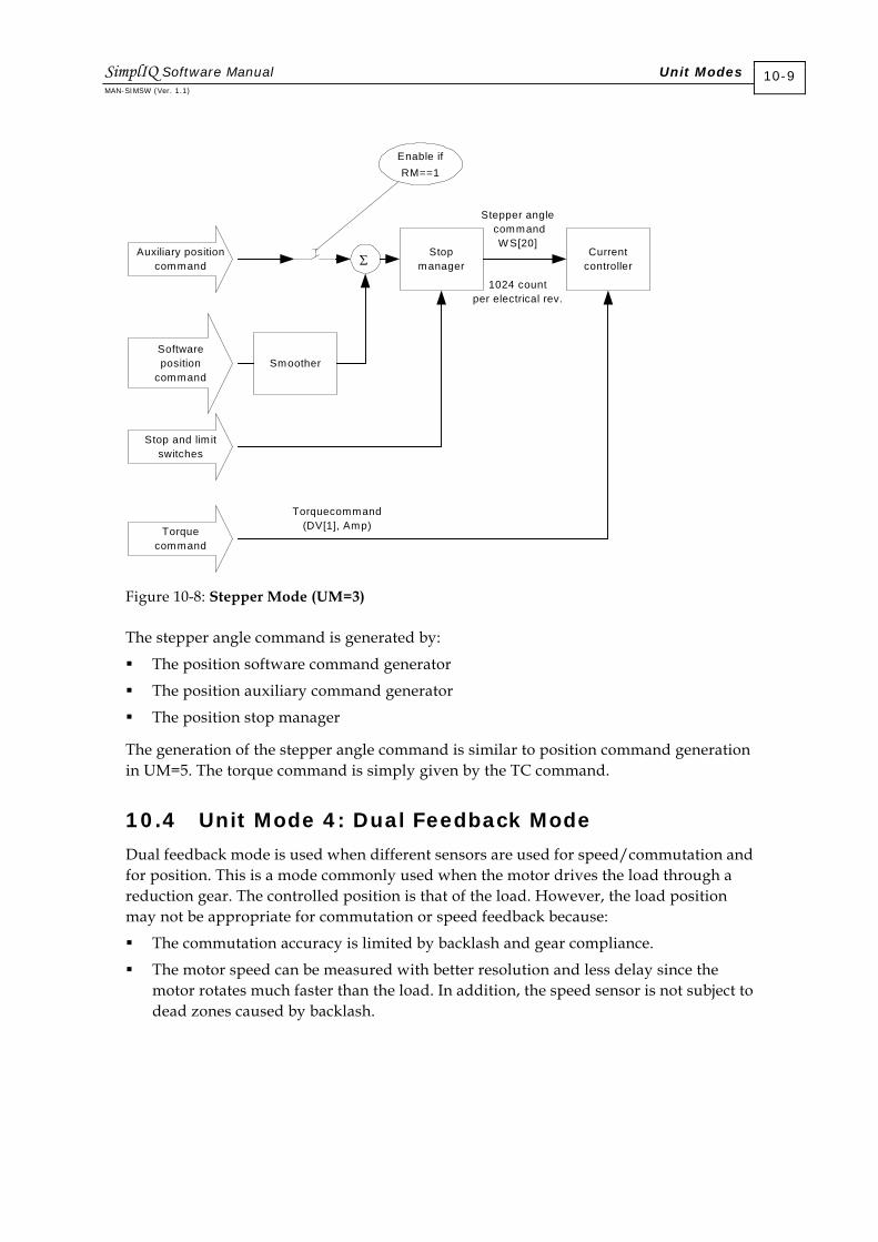
Softwareposition
command
Σ
Enable ifRM==1
Stepper angle command
W S[20]
Torquecommand(DV[1], Amp)
Auxiliary positioncommand
Stopmanager
Stop and limitswitches
Smoother
Torquecommand
Currentcontroller
1024 countper electrical rev.
Figure 10-8: Stepper Mode (UM=3)
The stepper angle command is generated by:
The position software command generator
The position auxiliary command generator
The position stop manager
The generation of the stepper angle command is similar to position command generation in UM=5. The torque command is simply given by the TC command.
10.4 Unit Mode 4: Dual Feedback Mode
Dual feedback mode is used when different sensors are used for speed/commutation and for position. This is a mode commonly used when the motor drives the load through a reduction gear. The controlled position is that of the load. However, the load position may not be appropriate for commutation or speed feedback because:
The commutation accuracy is limited by backlash and gear compliance.
The motor speed can be measured with better resolution and less delay since the motor rotates much faster than the load. In addition, the speed sensor is not subject to dead zones caused by backlash.
SimplIQ Software Manual Unit Modes MAN-SIMSW (Ver. 1.1)
10-9

Softwareposition
command
Σ
Enable ifRM==1
Auxiliary positioncommand
Stopmanager
Stop and lim itswitches
Smoother
d/dt
Position Controller
FF[2]
ΣΣ
Auxiliaryfeedbackencoder
main feedbackencoder
SpeedEstimator
- -Σ
DV[3]DV[2]
Speed Error
d/dt
Acceleration feed forward
FF[1]
Positioncorrection
Figure 10-9: Dual Feedback Mode (UM=4)
The position and speed commands are generated by:
The position software command generator
The position auxiliary command generator
The position stop manager
Generation of the position and speed commands is similar to the position and speed command generation of UM=5 and is described in Chapter 12.
The speed command, multiplied by the gain FF[2], is fed as reference to the speed controller in addition to position correction. Setting FF[2] exactly to the gear ratio between the position sensor and the speed sensor prevents steady-state constant-speed tracking errors.
The acceleration of the position command, multiplied by FF[1], can be injected directly as a torque command. By default, FF[1]=0. The reference values to the position, speed and torque controllers can be queried by DV[3], DV[2] and DV[1] respectively.
SimplIQ Software Manual Unit Modes MAN-SIMSW (Ver. 1.1)
10-10
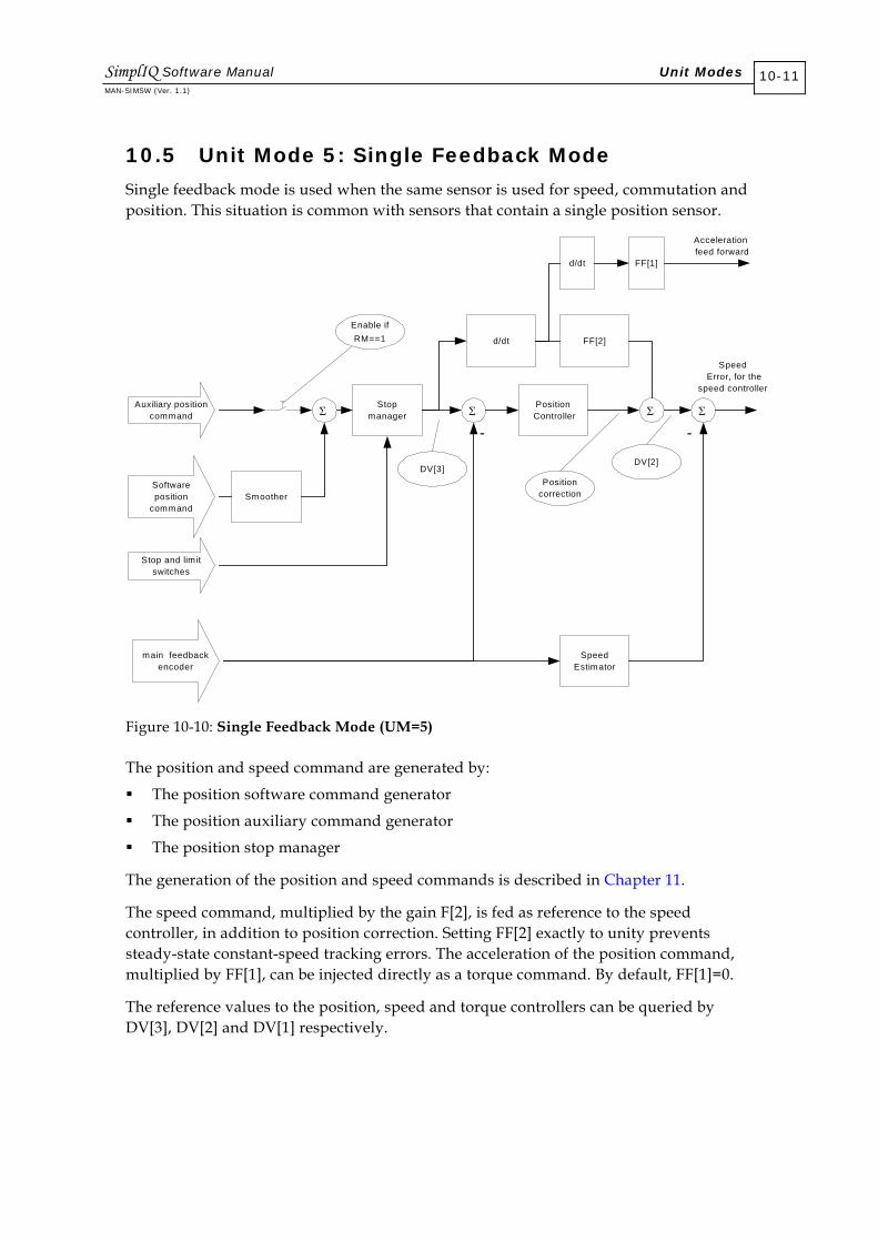
10.5 Unit Mode 5: Single Feedback Mode
Single feedback mode is used when the same sensor is used for speed, commutation and position. This situation is common with sensors that contain a single position sensor.
Softwareposition
command
Σ
Enable ifRM==1
Auxiliary positioncommand
Stopmanager
Stop and limitswitches
Smoother
d/dt
Position Controller
FF[2]
ΣΣ
main feedbackencoder
SpeedEstimator
- -Σ
DV[3]DV[2]
Speed Error, for the
speed controller
d/dt
Acceleration feed forward
FF[1]
Positioncorrection
Figure 10-10: Single Feedback Mode (UM=5)
The position and speed command are generated by:
The position software command generator
The position auxiliary command generator
The position stop manager
The generation of the position and speed commands is described in Chapter 11.
The speed command, multiplied by the gain F[2], is fed as reference to the speed controller, in addition to position correction. Setting FF[2] exactly to unity prevents steady-state constant-speed tracking errors. The acceleration of the position command, multiplied by FF[1], can be injected directly as a torque command. By default, FF[1]=0.
The reference values to the position, speed and torque controllers can be queried by DV[3], DV[2] and DV[1] respectively.
SimplIQ Software Manual Unit Modes MAN-SIMSW (Ver. 1.1)
10-11

Chapter 11: The Position Reference Generator
The position reference signal is generated by the following components
Software reference generator
External position reference generator
Stop manager
11.1 Software Reference Generator
The SimplIQ drive supports five modes of software referencing:
Idle: motor standing in place This is the default mode after setting motor on, and after an interpolated motion is complete.
PTP: point-to-point The user specifies the position in which the motor is to stand, and the limits subject to which the trajectory to the target should be designed. The SimplIQ drive automatically designs a minimum-time trajectory and executes it.
Jog The user specifies the speed at which the motor should steadily move and the acceleration limits to implement towards that speed. The SimplIQ drive automatically designs a minimum-time trajectory and executes it.
PT: position/time The user specifies a set of points to be visited at fixed points of time. The SimplIQ drive interpolates a third-order polynomial between the user’s points. The speeds at the user points are selected in order to form a smooth motion trajectory. Using PT, complex motions are easily designed. PT data may be transferred to the drive online using an efficient CAN PDO protocol, so that infinite PT motions are possible.
PVT: position/velocity/time The user specifies a set of motion points, each of which includes a position and the speed and time at which the position should be visited. The user points are interpolated using third-order polynomials. PVT mode allows absolute time specification so that several drives may compose a fully-synchronized motion. PVT data can be transferred to the drive online using an efficient CAN PDO protocol, so that infinite PVT motions are possible.
In order to initiate a software motion, its parameters must be initialized and a mode command issued. The next BG (software, hardware or timed) will start the motion. The following are the mode commands:
SimplIQ Software Manual The Position Reference Generator MAN-SIMSW (Ver. 1.1)
11-1

Command Mode ST Idle: ST stops any motion. PA PTP: PA=n specifies a PTP motion, to absolute position n counts. JV Jog: JV=n specifies a jog motion, at speed n counts/second. PT PT: PT=n specifies a PT motion, beginning from the nth item in the PT
data table. PV PVT: PV=n specifies a PVT motion, beginning from the nth item in the
PVT data table.
Table 11-1: Software Motion Mode Commands
11.1.1 Switching Between Motion Modes
The ST command can be used for stopping at any time. The drive will decelerate the position or velocity reference until it reaches a full stop.
PTP and jog motion commands can be sent anywhere, at any time. The drive will calculate the path to be followed so that the desired speed or position is reached, subject to the acceleration limits. PTP and jog motions can even be initiated during PVT or PT motion. Care must be taken, however, if the smooth factor (SF) is nonzero. Upon switching from interpolated motion to PTP or jogging, the PTP or jogging will start unsmoothed, with smoothing gradually building up, until after SF milliseconds, the motion is fully smoothed.
Care is also required when switching to tabulated (PT and PVT) motion modes. These modes should be started only when the motor is at a complete stop (MS=0 or MS=1), at the exact position specified as the first point for the PT or PVT. If the motor is not totally stopped at the correct start position, the software reference will jump. The command to the position controller will attempt to catch up with the PT or PVT motion, using the SD acceleration (refer to section 11.3).
11.1.2 Comparing PT and PVT Interpolated Modes
The following tables compare PT and PVT motion modes.
Feature PT PVT Motion buffer length 1024 64 Position points in one CAN message
2 1
Speed command calculation Automatic, by third-order interpolation
Specified by user
Acceleration command Automatic, by third-order interpolation
Automatic, by third-order interpolation
Time between user data points
Fixed multiple of the 1 - 255 controller sampling times. Cannot be changed on-the-fly.
Specified by user independently for each motion interval, in msec. Range: [1…255] msec.
SimplIQ Software Manual The Position Reference Generator MAN-SIMSW (Ver. 1.1)
11-2

Feature PT PVT Cyclical motion support Yes Yes On-the-fly motion programming with handshake host protocol
Yes Yes
Table 11-2: Tabulated Motion Differences
Feature Preferred
Long preprogrammed motions PT
Ease of use PT
Variable command sampling time PVT
Motion design independent of controller sampling time PVT
Synchronized, multiple-axis motions PVT
Table 11-3: Tabulated Feature Preferences
11.1.3 Idle Mode and Motion Status
After motor on, the position profiler is idle, meaning that the software position command is fixed. The idle mode is revisited whenever a mode terminates (a PTP or tabulated motion is completed) or a stop (ST) command is issued.
Idle mode is the only mode in the parameters of the external reference generator can be changed. This mode can be identified by the MS (motion status) variable, which can be read as follows:
MS Value Description
0 Position reference generator is idle and motor position is stabilized within target radius for a satisfactory length of time.
1 Position reference generator is idle or the motor is off (MO=0).
2 Position reference generator is active in one of the optional motion profilers: PTP, jog, PT or PVT.
Table 11-4: Motion Status Indications
When MS is 1 or less, the parameters of the external reference generator can be switched. The condition MS=0 implies that the motor position is indeed stabilized, meaning that the motor position is within the target radius, for at least the target time. The target radius is given by RS[1] counts, and the target time is TR[2] milliseconds.
SimplIQ Software Manual The Position Reference Generator MAN-SIMSW (Ver. 1.1)
11-3

Example: The concepts of target time and target radius are demonstrated in the following figure.
0.011 0.012 0.046 0.050 0.0740
200
400
600
800
1000
1200
1400
Target
Time
Figure 11-1: Target Time and Target Radius
In this figure, the motor position settles after overshooting the target of 1000 counts. The target radius is 20. The motor position is within the target radius in the range of [980…1020] counts.
Considering the dynamics of the example, it is reasonable to select the target time TR[2]=30. If too low a value is selected for TR[2], false “on-target” decision may result. For example, if the target time is set at 3 milliseconds, a final stabilization will be concluded at the time of 0.049 seconds, because during the time interval [0.046…0.049], the motor was within the allowed position error of [980…1020] counts.
11.1.4 Point-to-Point (PTP)
11.1.4.1 Basic PTP
In this motion mode, the motor moves from its present position to a final point at zero speed, and stays there. The trajectory to the final point is calculated based on speed, acceleration and deceleration limits, as set by the AC, DC and SP parameters respectively.
The largest PTP motion available is (XM[2] - XM[1])/2, because with modulo calculation, the PTP motion always goes the short way around. For example, if XM[1]=-500 and XM[2]=500, the present position reference is 490 and the command PA= -490. When BG is entered, the position reference increases and goes through 499 to -500, and then to -490. The total length of the movement will be 20 counts.
SimplIQ Software Manual The Position Reference Generator MAN-SIMSW (Ver. 1.1)
11-4

The parameters of PTP motion are summarized in the following table:
Parameter Action
AC Acceleration, in counts/second2
DC Deceleration, in counts/second2
SP Maximum speed, in counts/second
SF Smooth factor, in milliseconds
PR Relative position, in counts
PA Specifies that the next motion will be PTP, and the absolute target position
Table 11-5: PTP Motion Parameters
The PA command plays more than one role. PA=n specifies that the next BG will start a PTP motion. In addition, it specifies the target of the next PTP move.
In PTP mode, a BG command performs the following: PA=PA+PR Go to PA where: PA is the absolute position target. PR is the relative position target, enabling the specification of an incremental move or a series of incremental moves. PR is reset to zero by the PA=n command. Therefore, PA=n; BG initiates a motion towards n.
The value of PA is incremented automatically with PR every time a new motion is initiated. For example: PA=0; BG; while(MS==0); PR=1000; BG; while(MS==0); BG; while(MS==0); BG initiates four consecutive PTP motions, targeted at 0, 1000, 2000 and 3000 counts respectively.
PTP example: The simplest point-to-point motion is from a stationary position to another stationary position. The acceleration and final speed limits are: AC=100,000, DC=200,000, SP=2000, starting from PX=0 and PA=70; BG;
The following speed graph shows the acceleration, constant speed and deceleration in the trajectory to the target.
SimplIQ Software Manual The Position Reference Generator MAN-SIMSW (Ver. 1.1)
11-5

0 0.01 0.02 0.03 0.04 0.05 0.060
1000
2000
0 0.01 0.02 0.03 0.04 0.05 0.060
50
100
Speed
Acceleration(AC)
Constant speed(SP)
Deceleration(DC)
Position
With shorter movement, the deceleration begins before the speed limit is reached, so that the SP speed limit is not effective. This situation is depicted in the following figure:
0 0.01 0.02 0.03 0.04 0.05 0.06-500
0
500
1000
0 0.01 0.02 0.03 0.04 0.05 0.060
5
10
AC DC
Time (sec)
Time (sec)
Speed
Position
11.1.4.2 More Complex PTP Motions
PTP motions may be initiated any time, using the PA command, but not necessarily from a stationary state. The PTP decisions, made every position control cycle, are described in the following flowchart. All parameters in the flowchart — including AC, DC, SP and position target — are updated by a BG command, or by its hardware-activated equivalent.
SimplIQ Software Manual The Position Reference Generator MAN-SIMSW (Ver. 1.1)
11-6

S tar t
W ill s tea dy de c e le r a t ion a t D C s to p m o tio n be fo r e ta rg e t?
S pe ed > S P ?
S pe ed = S P ?
Y es
N o
Y es
A pp ly A C
M a in ta in S P
A pp ly D C
A pp ly D C
Figure 11-2: PTP Decisions Flowchart
Example of changing position target on-the-fly: The acceleration and final speed are: AC=100,000, DC=200,000, SP=20,000, starting from PX=0 and target position PA=100; BG; The position reference has not yet stabilized at the position target, when the position target is changed by the command PR=-400; BG; to the position target of (PA+PR)=-300. The drive calculates the position reference to reach the new target.
Note that in this example, the position reference overshoots the original position target of 100. This is because at the time that the position target was changed, the drive was approaching the target using DC. When a new target is set, the drive exits the state of final approach. Therefore, it uses the AC acceleration, which is smaller than DC in this example. With the reduced acceleration, it cannot avoid the overshoot.
0 0.05 0.1 0.15 0.2 0.25 0.3 0.35-10000
-5000
0
5000
0 0.05 0.1 0.15 0.2 0.25 0.3 0.35-400
-200
0
200
Counts/sec
Counts
Time (Sec)
Time(sec)
Position reference
Target position
AC DC
DC
AC
SimplIQ Software Manual The Position Reference Generator MAN-SIMSW (Ver. 1.1)
11-7

11.1.5 Jog
In a jogging motion, the motor receives a command to move at a fixed speed. The AC and DC parameters indicate the acceleration or deceleration to the desire speed.
Jog motions may be initiated any time by using the JV command, and not necessarily from a stationary state. The jog mode decisions, made every position control cycle, are given in the following flowchart.
Start
JV > 0 andSpeed > JV? Yes Apply DC
Speed = JV? Yes
Apply AC
Maintain JV
JV< 0 andSpeed < JV?
Yes Apply DC
Figure 11-3: Jog Decisions Flowchart
All parameters in the flowchart — including AC, DC, JV and the position target — are updated by a BG command or by its hardware equivalent (refer to the IL[N] command in the SimplIQ Command Reference Manual).
Jog motions can continue indefinitely. The position reference jumps by XM[2] - XM[1] when it reaches the modulo boundary, but the speed remains constant. The jog motion parameters are summarized in the following table:
Parameter Action
AC Acceleration, in counts/second2
DC Deceleration, in counts/second2
SF Smooth factor, in milliseconds
JV Jog velocity
Table 11-6: Jog Motion Parameters
The JV command specifies that the next motion will be a jog, and also what speed the jog will target.
SimplIQ Software Manual The Position Reference Generator MAN-SIMSW (Ver. 1.1)
11-8
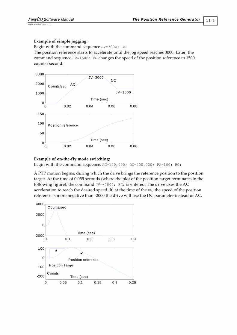
Example of simple jogging: Begin with the command sequence JV=3000; BG The position reference starts to accelerate until the jog speed reaches 3000. Later, the command sequence JV=1500; BG changes the speed of the position reference to 1500 counts/second.
0 0.02 0.04 0.06 0.080
1000
2000
3000
0 0.02 0.04 0.06 0.080
50
100
150
Time (sec)
Position reference
Counts/sec AC DC
JV=1500
JV=3000
Time (sec)
Example of on-the-fly mode switching: Begin with the command sequence: AC=100,000; DC=200,000; PA=100; BG;
A PTP motion begins, during which the drive brings the reference position to the position target. At the time of 0.055 seconds (where the plot of the position target terminates in the following figure), the command JV=-2000; BG; is entered. The drive uses the AC acceleration to reach the desired speed. If, at the time of the BG, the speed of the position reference is more negative than -2000 the drive will use the DC parameter instead of AC.
0 0.1 0.2 0.3 0.4-2000
0
2000
4000
0 0.05 0.1 0.15 0.2 0.25
-200
-100
0
100
Time (sec)
Time (sec)
Position reference Position Target
Counts/sec
Counts
SimplIQ Software Manual The Position Reference Generator MAN-SIMSW (Ver. 1.1)
11-9

11.1.6 Position - Velocity - Time (PVT)
In a PVT motion the user provides the desired position and speed at selected time instances. Between these specified times, the motion controller interpolates to obtain smooth motion. The position and speed specifications are absolute, while the time specification is relative.
A PVT motion can be referenced in absolute time by requiring it to start at a specified time. The BT (Begin on Time) command is used to start a PVT motion exactly at a given time, using a microsecond resolution.
The ability to relate PVT motions to absolute time makes them ideal for tightly-synchronized multiple-axis motions. For an explanation of how to synchronize the absolute time counters of multiple drives to the precision of a few microseconds, refer to the Elmo CAN Implementation Manual.
Example 1: The system should be at position 1000 and speed 100,000 counts/second at a given time, and at position 1620 and speed 110,000 counts/seconds 6 milliseconds later.
The first point is specified by: Position = 1000, Speed - 100,000, Time = (irrelevant to described motion, but relevant to the previous motion segment)
The second point is specified by: Position = 1620, Speed = 110,000, Time = 6 msec
The time is defined in milliseconds, not in drive sampling times. The drive interpolates the motion specification in order to calculate the desired position and speed at the sampling instances, when it needs the information.
PVT implements a third-order interpolation between the position - speed data provided by the user. For each motion interval, the user specifies the boundary positions and speeds. Mathematically, the user provides the following data:
Starting position and speed, denoted by P0 and V0, respectively
End position and speed, denoted by PT and VT, respectively
If t 0 denotes the starting time and T denotes the length of the time interval, the position for t ∈ [t 0, t 0 + T] is given by the third-order interpolating polynomial: P(t) = a(t – t 0)3 + b(t – t 0)2 + c(t – t 0) + c
The speed is given by: V(t) = 3a(t – t 0)2 + 2b(t – t 0) + c
SimplIQ Software Manual The Position Reference Generator MAN-SIMSW (Ver. 1.1)
11-10
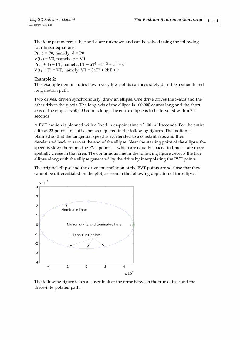
The four parameters a, b, c and d are unknown and can be solved using the following four linear equations: P(t 0) = P0, namely, d = P0 V(t 0) = V0, namely, c = V0 P(t 0 + T) = PT, namely, PT = aT3 + bT2 + cT + d V(t 0 + T) = VT, namely, VT = 3aT2 + 2bT + c
Example 2: This example demonstrates how a very few points can accurately describe a smooth and long motion path.
Two drives, driven synchronously, draw an ellipse. One drive drives the x-axis and the other drives the y-axis. The long axis of the ellipse is 100,000 counts long and the short axis of the ellipse is 50,000 counts long. The entire ellipse is to be traveled within 2.2 seconds.
A PVT motion is planned with a fixed inter-point time of 100 milliseconds. For the entire ellipse, 23 points are sufficient, as depicted in the following figures. The motion is planned so that the tangential speed is accelerated to a constant rate, and then decelerated back to zero at the end of the ellipse. Near the starting point of the ellipse, the speed is slow; therefore, the PVT points — which are equally spaced in time — are more spatially dense in that area. The continuous line in the following figure depicts the true ellipse along with the ellipse generated by the drive by interpolating the PVT points.
The original ellipse and the drive interpolation of the PVT points are so close that they cannot be differentiated on the plot, as seen in the following depiction of the ellipse.
-4 -2 0 2 4
x 104
-4
-3
-2
-1
0
1
2
3
4x 10
4
Nominal ellipse
Ellipse PVT points
Motion starts and teminates here
The following figure takes a closer look at the error between the true ellipse and the drive-interpolated path.
SimplIQ Software Manual The Position Reference Generator MAN-SIMSW (Ver. 1.1)
11-11

0 500 1000 1500 2000 25000
1
2
3
4
5
6
7
8
Difference(counts)
msec
It can be seen that with only 23 PVT points, the interpolated path never differs from the original ellipse by more than 8 counts (remember that the ellipse axes are 100,000 and 50,000 counts respectively)! At the PVT points, the interpolation error is zero.
The next figure displays the interpolated trajectories generated by the drive for the x-axis and for the y-axis.
0 500 1000 1500 2000 2500-6
-4
-2
0
2
4
6x 10
4
msec
Counts
X axis trajectory
Y axis trajectory
Example 3: The drive normally produces maximally smooth interpolating trajectories, which is why the ellipse in the previous example could be interpolated using so few points. Accurate corners, however, require non-smooth interpolation. Specifying zero speed for the corner points generates hard corners. The following graph shows a 2-axis synchronized PVT trajectory of an accurate rectangle.
SimplIQ Software Manual The Position Reference Generator MAN-SIMSW (Ver. 1.1)
11-12

-3 -2 -1 0 1 2 3
x 104
-2
-1
0
1
2x 10
4
0 5 10 15 20 25-2
-1
0
1
2x 10
5
x speedy speed
Counts/sec
PVT points
Rectangle
Counts
Counts
For the corner points both the x and y speeds are specified to zero. The interpolation error for the entire rectangle is zero.
Example 4: A PVT interpolation interval contains these values: Starting position = 1000 counts Starting speed = 100,000 counts/second End position = 1200 counts End speed = 190,000 counts/second Time = 6 milliseconds
The interpolated path for the data of the table, for a controller with a sampling time of 160 milliseconds, is depicted in the following figure. The + symbols indicate the points at integer multiples of the controller sampling time. At these points, the drive evaluates the interpolated motion path.
The end point does not necessarily fall on a controller sampling time. Strange-looking position commands may result if the speed choice is not consistent with the position and time definitions. The position distance and the time between points imply an average speed of (1200 - 1000)/0.006 = 33,000 counts/second. This average conflicts with the boundary point speed specifications of 100,000 counts/second and 190,000 counts/sec, respectively.
SimplIQ Software Manual The Position Reference Generator MAN-SIMSW (Ver. 1.1)
11-13

0 1 2 3 4 5 61000
1020
1040
1060
1080
1100
1120
1140
1160
1180
1200
Position
Time
11.1.6.1 The PVT Table
A three-column table is used to define PVT motion. Each row of the table defines the position and speed at a single time instance.
#Index P (32 Bits) V (24 Bits) T (8 Bits)
1 QP[1] QV[1] QT[1]
2 QP[2] QV[2] QT[2]
… QP… QV… QT…
64 QP[64] QV[64] QT[64]
Table 11-7: PVT Table
The table has 64 rows, enabling the specification of up to 63 consecutive PVT motion segments (64 segments if the table is used cyclically). The cells of the table may be accessed using the QP, QV and QT commands:
The QP[N] command sets/reads the nth row of the P column.
The QV[N] command sets/reads the nth row of the V column.
The QT[N] command sets/reads the nth row of the T column.
The first PVT point must be within the range XM[1]…XM[2]. the remaining PVT points need not be within modulo range; but the difference between consecutive PVT position points must be less than(XM[2] - XM[1])/2. For example, suppose that XM[1] = 0 and XM[2] = 1000. If the PVT describes a trajectory beginning at 0 and ending at 10,000, the motor will travel 10,000 counts, fully completing its position range 10 times.
SimplIQ Software Manual The Position Reference Generator MAN-SIMSW (Ver. 1.1)
11-14

11.1.6.2 Motion Management
In PVT mode, the drive manages a “read pointer” for the PVT table. When the read pointer is N, the present motion segment starts at the coordinates written on the Nth row of the table, and ends at the coordinates of the (N+1) row2.
When the time period specified by QT[N] elapses, the N segment is complete, the drive increments the read pointer to N+1, and then reads the N+2 PVT table row in order to calculate the parameters of the next motion segment.
The entire PVT table need not be used for a given motion. Its use is defined by the following parameters:
Parameter Use
MP[1] Lowest valid row of the PVT table
MP[2] Highest valid row of the PVT table
MP[3] A bit field: Bit 0 is: 0: Stop motion if read pointer reaches MP[2] 1: Continue motion when read pointer reaches MP[2]. The next row of the table is MP[1].
Bit 1 is: 0: PVT motion not expected to terminate. Issue an exception if it does. 1: PVT motion expected to terminate. When all data in PVT table has been used, exit PVT mode to Idle mode without issuing an emergency object.
Figure 11-4: PVT Motion Parameters
The following flowchart depicts the basic PVT mode. It assumes that the commands PV=N; BG; were entered, with 1 < N < 64.
The command PV=N sets the read pointer of the table to N and specifies that the next BG will start a PVT motion. BG then starts the motion.
The PVT table may be written online while PVT motion is being carried out. An infinite non-periodic motion can be generated in cyclical mode (MP[3]=1) by programming the PVT table on-the-fly.
2 The PVT mode may be cyclical, according to MP[3]. In this case, N+1 must be interpreted in the modulo sense.
SimplIQ Software Manual The Position Reference Generator MAN-SIMSW (Ver. 1.1)
11-15

Motionsegment
completed?
N >= MP[2]-1
Incrementread pointer
Read the N+1 row of the PVTtable and calculate the
parameters of the next motionsegment
Initialconditions:PVT read
pointer equalsN
Interpolateposition
command
Go toposition
controller
MP[3]==1
Exit PVT mode:Set Stop motion,
using the SDdeceleration
Set the readpointer to
MP[1]
Yes No
Yes
Yes
No
Figure 11-5: PVT Decisions Flowchart
The host must know how much free place is available in the PVT table in order to continue programming an executing PVT motion. This is achieved most efficiently by tracking the table read and write pointers. The host is aware of the write table status, because it controls writing to the table. If there is a doubt, the host can query MP[6]. The PV command is used to query the read pointer.
The read and write pointers can be mapped to a synchronous PDO, so that a CAN master can efficiently and continuously stay informed about the status of multiple drives running PVT in parallel in a network. Rather than polling the status of the PVT motion continuously, the host can use the queue underflow CAN emergency object as a request to refill the PVT table.
SimplIQ Software Manual The Position Reference Generator MAN-SIMSW (Ver. 1.1)
11-16
An unused part of the PVT table may be programmed for the next motion while the present motion is executing. An attempt to modify the data of an executing motion segment generates an error.
11.1.6.3 Mode Termination
PVT motion terminates upon of the following events:
The motor is shut down, either by programming MO=0 or by an exception.
Another mode of motion is set active; by programming PA=xxx; BG, for example. In this case, the new motion command executes immediately, without having to explicitly terminate the PVT mode.
The PVT motion manager runs out of data. This occurs when the read pointer reaches MP[2] and MP[3] is zero. This may also occur in auto-increment mode (CAN communications only) if the read pointer reaches the write pointer. In that case, the PVT motion is stopped immediately, using the SD deceleration. Note that if the last programmed PVT speed is zero, the PVT motion terminates neatly and the stop at the end of the motion does nothing.
11.1.6.4 PVT Motion Using CAN
The PVT table allows for the performance of both pre-designed and online motion plans. For online motion design, new entries can be written to the PVT table while the PVT motion is executing. The online motion design ability is limited by the speed of the communication interface.
With an RS-232 ASCII communication interface, a single PVT table row is programmed with the following format: QP[xx] = xxx,xxx,xxx; QV[xx] = x,xxx,xxx; QT[xx] = xxx; Up to 40 characters may be required to program a single PVT table row. At a communication rate of 19,200 baud, this may take 20 milliseconds. At a communication rate of 115,200 baud, this may take 4 milliseconds.
The CAN communication option allows must faster PVT table programming, by packing an entire PVT table row into one PDO communication packet. For easy synchronization with the host, the drive may be programmed to send the PVT read and write pointers continuously to the host as a synchronous PDO, or to send an emergency object whenever the number of yet unexecuted motion segments falls below a given threshold.
a. The PVT Motion Programming Message An entire row of the PVT table may be programmed by a single PDO — 0x200+ID — where ID is the node ID of the drive. Note that before using this PDO, it must be mapped to the object 0x2001. The PDO is mapped for the PVT mode as follows: Object dictionary index: 0x2001 Type: RECORD, three elements Access: Write only Structure: Signed32 position; Signed24 speed; Unsigned8 time PDO mapping: Yes Value limits No Default value: Not applicable
SimplIQ Software Manual The Position Reference Generator MAN-SIMSW (Ver. 1.1)
11-17

The PDO does not specify the PVT table row to be programmed; instead, a write pointer specifies the row. The parameter MP[6] initially sets the write pointer. A new PVT CANopen message (object 0x2001) write the data to the table row indicated by MP[6] and then automatically increments MP[6]. The CANopen auto-increment mode is described in the following flowchart:
Motionsegment
completed?
N >= MP[2]-1
Incrementread pointer
Read the read pointer row ofthe PVT table and calculatethe parameters of the next
motion segment
Initialconditions:PVT read
pointer equalsN
Interpolateposition
command
Go toposition
controller
Exit PVT mode:Set Stop motion,
using the SDdeceleration
Set the readpointer to
MP[1]
Yes
No
No
EMERGENCY:QUEUE
UNDERFLOW
MP[4]>0 and(Write pointer ==
N+1 orleft time < MP[4])
EMERGENCY:QUEUE LOWYes
No
Read pointer ==Write pointer Yes
Yes
Figure 11-6: PVT Auto-increment Mode Flowchart
SimplIQ Software Manual The Position Reference Generator MAN-SIMSW (Ver. 1.1)
11-18

This flow differs from the basic mode because:
The motion queue underflow is diagnosed by the read pointer reaching the write pointer.
Emergency objects are issued for the queue low and queue underflow events.
b. Programming Sequence for Auto-increment PVT Mode
PVT motion must begin with the initial programming of the PVT arrays. To do so, set: MP[1] = First valid line in PVT table MP[2] = Last valid array in PVT table MP[3] = 1 for cyclical mode MP[4] = Not relevant for PVT (PT only) MP[5] = Number of remaining programmed motion rows for issuing a “PVT queue low” emergency object. Set to zero if no “PVT queue low” warning is desired. MP[6] = Write pointer. This is the next position in the PVT table to be written by the CANopen object 0x2001.
Set the QP[N], QV[N] and QT[N] array elements for at least the first two rows of the PVT table. This is needed because PVT requires at least two time points for interpolating the motion trajectory.
If not already set, set UM=4 or UM=5, and MO=1. Set PV=N, assuming QP[N], QV[N], QT[N] and QP[N+1], QV[N+1], QT[N+1] are all programmed to valid values. Start the motion with a BG. Use the CAN PVT auto-increment command for the rest of the PVT motion.
When object 0x2001 is used to feed PVT reference points to the drive while a PVT motion is executing, the drive automatically enters Online Feed mode, in which the drive is aware of the position written and takes the following precautions:
If the feed is too slow, so that the drive must fetch unprogrammed points, the motion will abort with a “Queue underflow” emergency.
If the feed is too fast, so that points not yet used by the drive are overstruck, the drive will reject the feed attempt with a “Queue overflow” emergency.
The Online Feed mode will continue until the end of the current PVT motion and will not be applied to the next motion.
To stay informed about how the PVT motion is advancing, the read and write PVT table pointers can be received continuously, mapped to a synchronous PDO, or the “Queue low” emergency signal can be used to indicate the need for more data. The “Queue low” emergency message includes the present location of the read pointer and the write pointer. It is safe to send more PVT data PDOs until the write pointer is one location before the read pointer specified by the “Queue low” emergency message.
The host is well aware of the location of the write pointer, because it can count its own messages. However, a data message may be rejected because the queue is full, or because a message has been lost. In such a case, the drive issues an emergency object to the host. After receiving the object, the true location of the write pointer may be unclear. The host may then set MP[6] to the possibly-rejected table row and continue writing from there.
SimplIQ Software Manual The Position Reference Generator MAN-SIMSW (Ver. 1.1)
11-19

MP[5] (number of rows remaining for “Queue low” emergency) should not be set to too high a value. For example, consider a slow-responding host that manages a 64-row PVT queue in the drive. Suppose that the PVT row times are 10 milliseconds each and that MP[5] = 55. The host receives a “Queue low” emergency object notifying it that there are 64 - 55+1 = 8 free programmable rows in the PVT table. Suppose that the host takes 50 milliseconds to respond, and 5 milliseconds to program each row. The 8 rows will have been programmed after 90 milliseconds. In the meantime, 9 additional PVT table rows will have been executed, and there are only 54 valid rows in the PVT table. Because 54 is lower than MP[5], there will be no more “Queue low” emergency messages until the PVT table is exhausted, and PVT mode is terminated. The situation can be remedied if the host requests the drive for a PV (location of read pointer) after the PVT table writes are complete. If PV < MP[5], the programming process has taken too much time, and the writing must be continued.
Accurate timing with respect to the host is the essence of multiple-axis synchronized motion. Such timing can be achieved by using the CAN SYNC signal and the CAN synchronized BG service, as described in the Elmo CAN Implementation Manual.
11.1.6.5 PVT Motion Mode Parameters
The following parameters apply to PVT motion:
Parameter Use Comment
UM (Unit Mode) Units modes 3, 4 and 5 select the position modes.
SD (Stop Deceleration) Rate of deceleration when motion is killed by queue underflow or exception. The rate of acceleration to catch up if PVT is started with improper initial connections.
PV (Position/Velocity/ Time)
Set a PVT motion command
QP[N], QV[N], QT[N]: PVT table entries
Set values to PVT table PVT table elements can also be set using PDOs.
MP (Motion Parameters) MP[1] = First valid row in PVT table.
MP[2] = Last valid row in PVT table.
MP[3]: Bit0 = Cyclical motion (0: Non-cyclical, 1: Cyclical) Bit1 = Expected stop (0: Issue emergency on stop; 1; Expect stop)
MP[5] = Number of yet unexecuted table rows for “Queue low” alarm.
MP[6] = Initial value for write pointer
Configure a PT or PVT motion. MP[6] and MP[5] are for CANopen auto-increment mode only.
Figure 11-7: PVT-related Parameters
SimplIQ Software Manual The Position Reference Generator MAN-SIMSW (Ver. 1.1)
11-20

The following CAN emergencies are supported:
Error Code (Hex)
Error Code (Dec)
Reason
Data Field
0x56 86 Queue is low. Number of yet unexecuted PVT table rows has dropped below the value stated in MP[4].
Field 1: Write pointer Field 2: Read pointer
0x5b 91 Write pointer is out of physical range ([1…64]) of PVT table. Reason may be an improper setting of MP[6].
Value of MP[6]
0x5c 92 PDO 0x3xx is not mapped.
0x34 52 An attempt has been made to program more PVT points than are available in queue.
Field 1: Index of PVT table entry that could not be programmed
0x7 7 Cannot initialize motion due to bad setup data. The write pointer is outside the range specified by the start and end pointers.
0x8 8 Mode terminated and motor has been automatically stopped (in MO=1).
Data field 1: Write pointer
Data field 2: 1: End of trajectory in non-cyclical mode 2: A zero or negative time specified for a motion interval 3: Read pointer reached write pointer
0x9 9 A CAN message has been lost.
Figure 11-8: PVT CAN Emergency Messages
11.1.7 Position - Time (PT)
In a PT motion, the user specifies a sequence of absolute positions with equal time spaces to be visited by the drive. The time space must be an integer multiple of the drive sampling time. Between the user-specified positions, the drive interpolates smooth motion. The position specifications are absolute.
SimplIQ Software Manual The Position Reference Generator MAN-SIMSW (Ver. 1.1)
11-21

11.1.7.1 Interpolation Mathematics
PT implements a third-order interpolation between the position data points provided by the user.
Let T = m * Ts where: Ts is the sampling time of the position controller. The parameter WS[28] reads Ts. T is the sampling time of the PT trajectory. m (system parameter MP[4]) is the integer parameter that relates Ts and T.
For m = 1, no interpolation is required. For m > 1, there are certain sampling instances of the position controller for which the path command must be interpolated, using a third-order polynomial interpolation.
The user provides position points P(k), k = 1…N. The drive calculates the speeds V(k), k=1…N for points P(k), k=1…N as follows:
If k is an ordinary point inside the path:
T2)1k(P)1k(P)k(V −−+
=
If k is the first programmed point in the path:
T)k(P)1k(P)k(V −+
=
If k is the last programmed point in the path:
T)1k(P)k(P)k(V −−
=
For each motion interval, four requirements must be satisfied:
Start position
End position
Start speed
End speed
These four requirements exactly suffice for solving the third-order interpolating polynomial.
Example: Consider the position controller reference signal P(t) - sin(2π * 10t) where t is the time in seconds.
The controller sampling time is 200 microseconds and the path is programmed with a data point once per MP[4] = 50 controller sampling times (10 milliseconds). The PT reference points are depicted as circles in the following graph. The path interpolated by the drive is shown as a solid line.
SimplIQ Software Manual The Position Reference Generator MAN-SIMSW (Ver. 1.1)
11-22

0 0.02 0.04 0.06 0.08 0.1-1000
-800
-600
-400
-200
0
200
400
600
800
1000Interpolated pathPvtPlan output
Time (seconds)
Motion path in counts
11.1.7.2 The PT Table
The vector QP[N] defines the position points for PT motion. Each element of the vector defines the position at a given time. The QP vector has 1024 elements, and can therefore specify up to 1023 consecutive PT motion segments, or 1024 PT motion segments in cyclical mode.
The first PT point must be within the range XM[1]…XM[2]. The remaining PT points need not be within modulo range; but the difference between consecutive PT position points must be less than (XM[2] - XM[1])/2. For example, suppose that XM[1] = 0 and XM[2] = 1000. If the PT describes a trajectory beginning at 0 and ending at 10,000, the motor will travel 10,000 counts, completing its position range 10 times.
11.1.7.3 Motion Management
In PT mode, the drive manages a “read pointer” for the QP[N] vector. When the read pointer is N, the present motion segment starts at position QP[N] and ends at QP(N+1)3. After MP[4] control sampling times, the drive increments the read pointer to N+1, and reads QP[N+2] to calculate the parameters of the next motion segment.
The entire PT table need not be used for a given motion.
3 The PT mode may be cyclical, according to [MP3]. In this case, N+1 must be interpreted in the modulo sense.
SimplIQ Software Manual The Position Reference Generator MAN-SIMSW (Ver. 1.1)
11-23

The parameters of a PT motion are summarized in the following table:
Parameter Use Comment
MP[1] Lowest valid element of QP vector.
MP[2] Highest valid row of QP vector.
MP[3] 0: Motion stops if read pointer reaches MP[2]. 1: Motion continues when read pointer reaches MP[2]. The next row of the table is MP[1].
Cyclical behavior definition.
MP[4] Number of controller sampling times in each PT motion segment.
Table 11-8: PT Motion Parameters
The following flowchart depicts the basic PT mode:
Motionsegment
completed?
N >= MP[2]-1
Incrementread pointer
Read the N+1 element of thePQ vector and calculate the
parameters of the next motionsegment
Initialconditions:PT read
pointer equalsN
Interpolateposition
command
Go toposition
controller
MP[3]==1
Exit PT mode:Set Stop motion,
using the SDdeceleration
Set the readpointer to
MP[1]
Yes No
Yes
Yes
No
Figure 11-9: PT Decisions Flowchart
SimplIQ Software Manual The Position Reference Generator MAN-SIMSW (Ver. 1.1)
11-24

A PT motion is initiated by stating: PT=N with 1 < N < 1024, and BG. The PT=N command sets the read pointer of the QP vector to N. BG starts the motion.
The QP vector may be written online during a PT motion, as long as no presently-executing PT elements are programmed.
a. Mode Termination The PT motion terminates when one of the following occurs:
The motor is shut down, either by programming MO=0 or by an exception.
Another mode of motion is set active; by programming PA=xxx; BG, for example. In this case, the new motion command executes immediately, without having to explicitly terminate the PT mode.
The PT motion manager runs out of data. This occurs when the read pointer reaches MP[2] and MP[3] is zero. This may also occur in auto-increment mode (CAN communications only) if the read pointer reaches the write pointer. In that case, the PT motion is stopped immediately, using the SD deceleration. Note that if the last programmed PT speed is zero, the PT motion terminates neatly.
b. PVT Motion Using CAN
The PT table allows for the performance of both pre-designed and online motion plans by writing the QP vector while PT motion is executing. The online motion design ability is limited by the speed of the communication interface. With an RS-232 ASCII communication interface, a single QP vector is programmed with the following format: QP[xx] = xxx,xxx,xxx; Up to 18 characters may be required to program a single position point. At a communication rate of 19,200 baud, this may take 9 milliseconds. At a communication rate of 115,200 baud, this may take 1.8 milliseconds.
The CAN communication option allows must faster PT programming, by packing two position points into one PDO communication packet. For easy synchronization with the host, the drive may be programmed to send the PT read and write pointers continuously to the host as a synchronous PDO, or to send an emergency object whenever the number of yet unexecuted motion segments falls below a given threshold.
c. The PT Motion Programming Message
Two positions for the QP vector can be programmed in the eight bytes of a single PDO — 0x300+ID — where ID is the node ID of the drive. Note that before using this PDO, it must be mapped as follows:
Object dictionary index: 0x2002 Type: RECORD, two elements Access: Write only Structure: Signed32 Position1; Signed32 Position2 PDO mapping: Yes Value limits No Default value: Not applicable
SimplIQ Software Manual The Position Reference Generator MAN-SIMSW (Ver. 1.1)
11-25
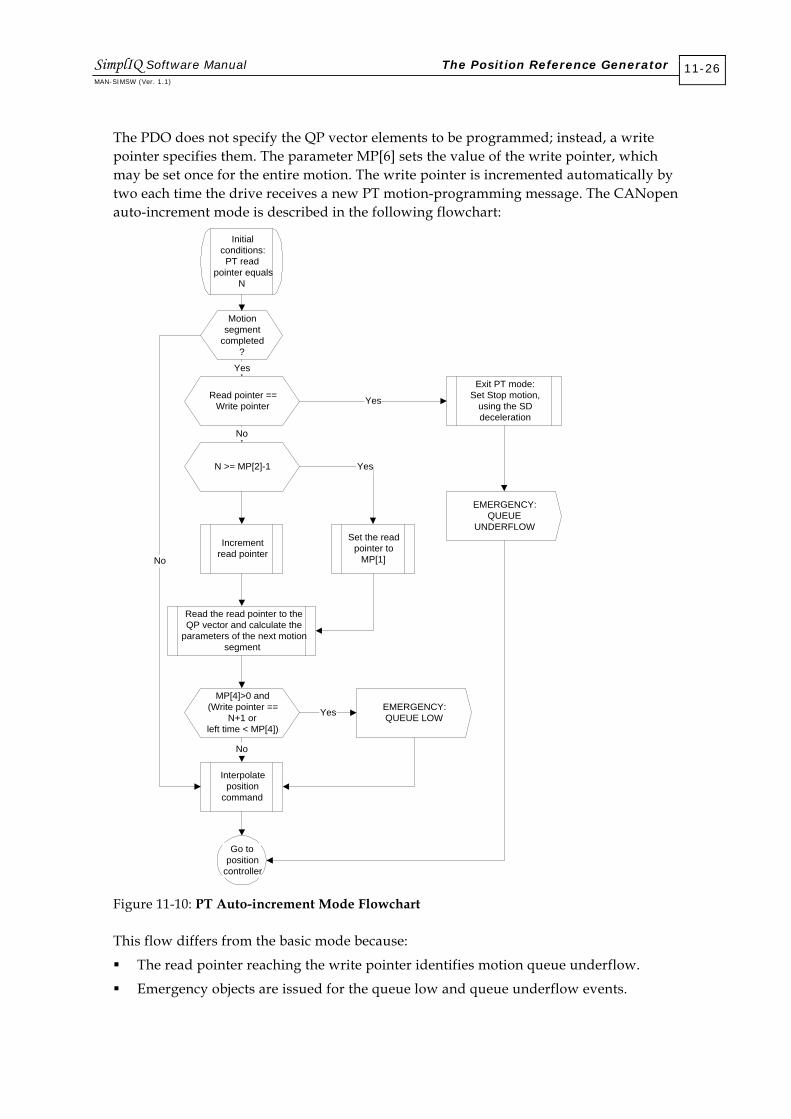
The PDO does not specify the QP vector elements to be programmed; instead, a write pointer specifies them. The parameter MP[6] sets the value of the write pointer, which may be set once for the entire motion. The write pointer is incremented automatically by two each time the drive receives a new PT motion-programming message. The CANopen auto-increment mode is described in the following flowchart:
Motionsegment
completed?
N >= MP[2]-1
Incrementread pointer
Read the read pointer to theQP vector and calculate the
parameters of the next motionsegment
Initialconditions:PT read
pointer equalsN
Interpolateposition
command
Go toposition
controller
Exit PT mode:Set Stop motion,
using the SDdeceleration
Set the readpointer to
MP[1]
Yes
No
No
EMERGENCY:QUEUE
UNDERFLOW
MP[4]>0 and(Write pointer ==
N+1 orleft time < MP[4])
EMERGENCY:QUEUE LOWYes
No
Read pointer ==Write pointer Yes
Yes
Figure 11-10: PT Auto-increment Mode Flowchart
This flow differs from the basic mode because:
The read pointer reaching the write pointer identifies motion queue underflow.
Emergency objects are issued for the queue low and queue underflow events.
SimplIQ Software Manual The Position Reference Generator MAN-SIMSW (Ver. 1.1)
11-26
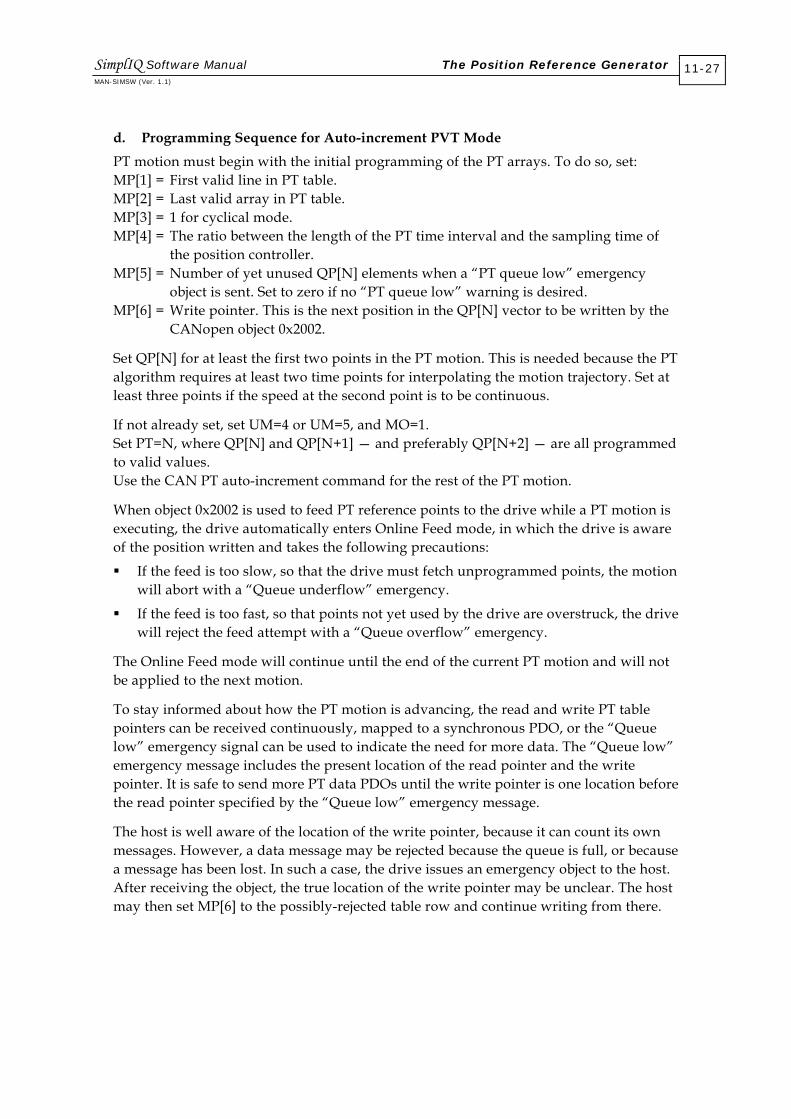
d. Programming Sequence for Auto-increment PVT Mode
PT motion must begin with the initial programming of the PT arrays. To do so, set: MP[1] = First valid line in PT table. MP[2] = Last valid array in PT table. MP[3] = 1 for cyclical mode. MP[4] = The ratio between the length of the PT time interval and the sampling time of the position controller. MP[5] = Number of yet unused QP[N] elements when a “PT queue low” emergency object is sent. Set to zero if no “PT queue low” warning is desired. MP[6] = Write pointer. This is the next position in the QP[N] vector to be written by the CANopen object 0x2002.
Set QP[N] for at least the first two points in the PT motion. This is needed because the PT algorithm requires at least two time points for interpolating the motion trajectory. Set at least three points if the speed at the second point is to be continuous.
If not already set, set UM=4 or UM=5, and MO=1. Set PT=N, where QP[N] and QP[N+1] — and preferably QP[N+2] — are all programmed to valid values. Use the CAN PT auto-increment command for the rest of the PT motion.
When object 0x2002 is used to feed PT reference points to the drive while a PT motion is executing, the drive automatically enters Online Feed mode, in which the drive is aware of the position written and takes the following precautions:
If the feed is too slow, so that the drive must fetch unprogrammed points, the motion will abort with a “Queue underflow” emergency.
If the feed is too fast, so that points not yet used by the drive are overstruck, the drive will reject the feed attempt with a “Queue overflow” emergency.
The Online Feed mode will continue until the end of the current PT motion and will not be applied to the next motion.
To stay informed about how the PT motion is advancing, the read and write PT table pointers can be received continuously, mapped to a synchronous PDO, or the “Queue low” emergency signal can be used to indicate the need for more data. The “Queue low” emergency message includes the present location of the read pointer and the write pointer. It is safe to send more PT data PDOs until the write pointer is one location before the read pointer specified by the “Queue low” emergency message.
The host is well aware of the location of the write pointer, because it can count its own messages. However, a data message may be rejected because the queue is full, or because a message has been lost. In such a case, the drive issues an emergency object to the host. After receiving the object, the true location of the write pointer may be unclear. The host may then set MP[6] to the possibly-rejected table row and continue writing from there.
SimplIQ Software Manual The Position Reference Generator MAN-SIMSW (Ver. 1.1)
11-27

11.1.7.4 PT Motion Mode Parameters
The following parameters apply to PT motion:
Parameter Use Comment
UM (Unit Mode) Units modes 3, 4 and 5 select the position mode.
SD (Stop Deceleration) Rate of deceleration when motion is killed by queue underflow or exception. SD is also the acceleration to catch up with a PT motion started with improper initial connections.
PV (Position/Time) Set a PT motion command. Special features are available for PT using CAN communication.
QP[N]: PT table entries Set values to PT table.
MP (Motion Parameters) MP[1] = First valid row in PT table.
MP[2] = Last valid row in PT table.
MP[3]: Bit0 = Cyclical motion (0: Non-cyclical, 1: Cyclical).
MP[4] = Ratio between command sampling time and position controller sampling time.
MP[5] = Time for “Queue low” alarm.
MP[6] = Initial value for write pointer.
Configure a PT or PVT motion. MP[6] and MP[5] are for CANopen auto-increment mode only.
WS[28] Sampling time of the position controller, in microseconds.
A read-only parameter. WS[28] is an integer multiple of the basic sampling time as set by TS.
Figure 11-11: PT-related Parameters
SimplIQ Software Manual The Position Reference Generator MAN-SIMSW (Ver. 1.1)
11-28

The following CAN emergencies are supported:
Error Code (Hex)
Error Code (Dec)
Reason
Data Field1
0x56 86 The time for the entire remaining valid PT program has dropped below the value stated in MP[4].
Time (milliseconds) remaining with valid motion program.
0x5b 91 Write pointer is out of physical range ([1…1024]) of QP vector. Reason may be an improper setting of MP[6].
Value of MP[6]
0x5c 92 PDO 0x3xx is not mapped.
0x34 52 An attempt was made to program more PT points than supported by queue.
Index of PT table entry that could not be programmed
0x7 7 Cannot initialize motion due to bad setup data. The write pointer is outside the range specified by the start pointer and the end pointer.
0x8 8 Mode terminated and motor has been automatically stopped (in MO=1). Reasons:
End of trajectory in non-cyclical mode (MP[3] = 0 ) [additional code 1]
A zero or negative time was specified for a motion interval [additional code 2]
Read pointer reached write pointer [additional code 3]
Read pointer.
Figure 11-12: PVT CAN Emergency Messages
11.2 The External Position Reference Generator This section summarizes how the drive generates the external motion command for the position controller. The external position reference is useful for: Positioning a manipulator on a moving object. The desired position of the
manipulator with respect to the object on the conveyor can be programmed as a software motion, such as PTP or PVT. The position of the conveyor is not known in advance and must be measured online; using the auxiliary encoder input, for example. The reading of the auxiliary input is scaled by the follower ratio parameter (FR[3]), and added to the software command.
Driving the drive as a slave in a larger arrangement. For example, when the drive moves a valve in a pressure control system, its position command may be an analog output of a pressure controller.
SimplIQ Software Manual The Position Reference Generator MAN-SIMSW (Ver. 1.1)
11-29

Synchronizing several drives, which may be driven by an auxiliary encoder signal. Each of the drives uses its ECAM table to derive its own motion path from the auxiliary signal.
The external position reference is generated by the following scheme:
Auxiliary encoderinput
Auxiliary positioncommand
FR[3]
ECAM table Use ECAMif EM[1]>0
DV[6]
Figure 11-13: External Position Reference Generator
The following parameters determine the composition of the position reference:
Parameter Action
FR[3] Scale the auxiliary encoder input. Applicable only if the auxiliary encoder is not used for position feedback.
EM[1] Define whether the ECAM table transforms the external reference: EM[1]=0: Do not use ECAM table. EM[1]=1: Use linear ECAM table to transform external command. EM[1]=2: Use cyclical ECAM table to transform external command.
RM Define whether an external reference is used: RM=0: Do not use external reference. RM=1: Use external reference.
DV[6] Reads the external position reference.
Table 11-9: Position Reference Parameters
11.2.1 Follower
In Follower mode (RM=1, EM[1]=0), the external speed command tracks the auxiliary encoder speed at a ratio of FR[3], as depicted in Figure 11-14. In this figure, the auxiliary encoder counts PY modulo in the range [0…500]. The derived external position reference advances at the same rate as the auxiliary encoder while FR[3]=1. Jumps in PY due to the modulo count are not reflected in auxiliary position reference DV[6]. When FR[3] changes to 2, DV[6] advances at twice the speed of PY.
SimplIQ Software Manual The Position Reference Generator MAN-SIMSW (Ver. 1.1)
11-30

0 0.005 0.01 0.015 0.02 0.025 0.030
200
400
600
800
1000
1200
1400
1600
1800
Time
PY - Auxiliary PositionDV[6] - External Position Reference
FR[3]=1 FR[3]=2
FR[3]changes
Figure 11-14: Follower Ratio
Example: This example illustrates how a moving object is handled by the application:
X axis
Y a
xis
Moving conveyer
Cake
Circle todraw
10000
In this application, an x-y stage draws a chocolate picture on a cake while the cake travels on a conveyor. The drawing must be accurate with respect to the cake.
In order to draw a circle of radius 10,000 encoder counts on the cake in one second, the x-axis motor must follow the trajectory: x(t) = 10,000 * cos(2πt) + c(t) where c(t) is the position of the conveyor.
If the conveyor has an encoder, it can be used to compensate for its motion.
SimplIQ Software Manual The Position Reference Generator MAN-SIMSW (Ver. 1.1)
11-31

Suppose that the resolution of the conveyor encoder is similar to the resolution of the x-axis encoder. To draw an exact circle on the moving cake, the motion 10,000 * cos(2πt) is programmed as PVT and RM=1, FR[3]=1.
0 0.2 0.4 0.6 0.8 1-1
0
1
2
3
4x 10
4
x motion relative to cake
Conveyer position, as measuredby the auxiliary encoder input
x motor motion command
Time (sec)
11.2.2 ECAM
ECAM is an acronym for electronic CAM, in which the position reference to the drive is not directly proportional to the total external inputs, but is rather a function of them.
The ECAM-related commands are as follows:
Commands Action
EM[1] Indicates whether the ECAM function is active: 2: ECAM is cyclical. 1: ECAM is linear. 0: Direct external referencing.
Set EM[1] to synchronously activate the most recent settings of EM[2], EM[3], EM[4], EM[5] and EM[7].
EM[2] Last valid index of ECAM table. Maximum for EM[2] is 1024. The EM[2] setting goes into effect only at next setting of EM[1] or next MO=1.
EM[3] Starting position: value of the input to the ECAM function for which the output of the ECAM function will be ET[EM[5]] (ET of EM[5]). If EM[3] is out of range for PY, it will be taken modulo PY.
EM[4] Table difference (see sections 11.2.2.1 and 11.2.2.2). The EM[2] setting goes into effect at next setting of EM[4] or next MO=1.
EM[5] First valid index of ECAM table. The EM[2] setting goes into effect at next setting of EM[5] or next
SimplIQ Software Manual The Position Reference Generator MAN-SIMSW (Ver. 1.1)
11-32

Commands Action MO=1.
EM[6] Write pointer for fast loading of ECAM table via CAN bus (see section 11.2.4).
EM[7] Last interval shortening. EM[7] allows the ECAM table length (ECAM cycle in the EM[1]=2 cyclical mode) not to be an integer multiple of EM[4] (see sections 11.2.2.1 and 11.2.2.2).
EM[8] Reports present executing segment of ECAM table. Used to determine if an action is executing or is complete.
Table 11-10: ECAM-related Commands
The input to the ECAM table (IET) is FR[3] * (auxiliary encoder - EM[3]).
The ECAM table defines the external position reference for IET values between 0 and IETmax = (EM[2] - EM[5]) * EM[4] - EM[7].
11.2.2.1 Linear ECAM
Linear ECAM is selected by EM[1]=1. In this mode:
If IET < 0, the external position command (output of the ECAM table) will be ET[EM[5]].
If IET > IETmax, the external position command will be ET[EM[2]].
If 0 < IET < IETmax, the external position command will be derived by linear interpolation of the ECAM table.
The output of the ECAM table does not need to be in the range of the main position sensor (refer to the XM[N] command section in the SimplIQ Command Reference Manual). If the output of the ECAM table is out of the position sensor range, it is interpreted modulo the position sensor range.
Example 1: The following figure illustrates the behavior of linear ECAM for EM[5]=1 and EM[2]=4.
SimplIQ Software Manual The Position Reference Generator MAN-SIMSW (Ver. 1.1)
11-33

Ext
erna
l pos
ition
com
man
d
ECAM table input
0
EM[4]
ET[3]
EM[4]-EM[7]
ET[1]
ET[2]
ET[4]
EM[4]
IETmax
Figure 11-15: Linear ECAM
Example 2: Consider an application in which a two-axis x-y servo system is used to plot chocolate bears on birthday cakes:
Head contour
Eyes
Cake
moves
The cakes come from the oven on a conveyor. An incremental encoder measures the position of the conveyor. Each time a new cake arrives, it activates the DIN#1 input of the drive. In response to DIN#1, the x-y axes begin to contour the head of the bear, drawing it with chocolate. The chocolate flow is stopped while the x-y axis travels towards the start of the bear eyes. After the eyes are drawn, the x-y stage returns to its initial position, ready for another cake.
Both drives that manage the x and y axes operate in ECAM mode. They get their position reference as a function of the location of the conveyor, via the auxiliary encoder input. The ECAM motion starts when a cake arrives at the plotting station and continues until the conveyor travels 4000 counts.
One of the drives uses a digital output to control the flow of the chocolate out of the drawing nozzle.
SimplIQ Software Manual The Position Reference Generator MAN-SIMSW (Ver. 1.1)
11-34

The drive program is: IL[1]=7 Program DIN#1 as general-purpose input. EM[1]=1 Enable ECAM. EM[2]=200 Length of ECAM vector. EM[3]=0 Starting position. EM[4]=100 Conveyor encoder counts between two consecutive ECAM table entries. ET[1]=…;ET[2]=…;ET[100]…; Program numeric data of ECAM table. If ECAM table data is changed from cake to cake, consider loading ECAM table using fast CAN loading method. UM=5 Set single sensor position mode. RM=1 Enable external referencing. FR[3]=0; Kill external input. MO=1 Start motor. PA=1000;BG Go to waiting position. HY[2]=0;HY[3]=9;HY[1]=1 Null auxiliary encoder count upon cake arrival (DIN#1 high).
Each drive has the following AUTO_I1 routine: function AUTO_I1 DIN#1 has operated an already-programmed auxiliary homing process to synchronize the following input. OB[1]=1; Activate chocolate flow. FR[3]=1; Enable auxiliary encoder input with follower ratio of 1. until (PY >= 2000) Wait until end of head contour. OB[1]=0; Stop chocolate. until (PY >= 3000) Go to start of eyes. OB[1]=1; Restart chocolate. until (PY >= 4000) Draw eyes. OB[1]=0 Stop chocolate. FR[3]=0;PA=1000;BG; Return to starting point. HY[1]=1 Program auxiliary encoder to reset at next cake. return End of auto subroutine.
11.2.2.2 Cyclical ECAM
Cyclical ECAM mode is selected by EM[1]=2. In this mode, the master (auxiliary encoder input) can advance indefinitely. The ECAM table defines the slave (motor position) command for one master period, which is the input range to the ECAM table, IETmax.
In each master period (in which the master completes a travel of IETmax/FR[3] counts), the slave advances by ET[EM[2]] - ET[EM[5]]. The following figure illustrates the behavior of cyclical ECAM for EM[5]=1 and EM[2]=4.
SimplIQ Software Manual The Position Reference Generator MAN-SIMSW (Ver. 1.1)
11-35

Ext
erna
l pos
ition
com
man
d
ECAM table input
0
EM[4]
ET[3]
EM[4]-EM[7]
ET[1]
ET[2]
ET[4]
EM[4]
IETmax 2 IETmax
ET[EM[2]]-ET[EM[5]]
Figure 11-16: Cyclical ECAM
Note that the external position command is summed from the ECAM table outcome and a cumulative offset, which is n x (ET[EM[2]] = ET[EM[5]]) with n being an integer.
The cumulative offset is lost in the following circumstances:
Homing changes the auxiliary position counter value.
FR[3] is changed.
EM[1] is changed.
EM[1] is set to the existing value, with EM[2], EM[3], EM[4] or EM[5] changed.
When the cumulative offset is lost, and if the software reference generator is not running an interpolated mode, the software reference is automatically adjusted by the same value so that the motor will not jump (refer to section 11.2.5.1).
11.2.3 Dividing the ECAM Table into Logical Portions
The ECAM table can store several distinct movements, with a portion of the table used for each movement. This enables a future movement to be programmed into the drive while the present movement is executing.
SimplIQ Software Manual The Position Reference Generator MAN-SIMSW (Ver. 1.1)
11-36

Example: In the previous example of the chocolate bear, it was assumed that the bear drawing could be programmed one time only. In many food applications, however, the products to be worked on (the cake in the example) are not placed exactly on the conveyor or their shapes may be irregular. A camera images the next coming product and the image is analyzed to form the next motion path. The motion path for the analyzed image is communicated to the drive by the system controller while the drive works on a previously-programmed path, as depicted in the following figure:
Cake
Drawing x-y manipulatorstation
Next cake
Camera station
CAN
Camera
Assume that the drive at the x-y manipulator station runs ECAM table entries ET[1]…ET[100]. In the meantime, the system controller programs the next shape to run ET[101]…ET[200]. The preferred method to achieve this is to use the fast CAN ECAM points protocol. While the x-y manipulator works on ECAM table entries ET[101]…ET[2000], the system controller programs ET[1]…ET[100] again, and so on.
The AUTO_RLS program of the previous example is now slightly modified to: function AUTO_I1 DIN#1 has operated an already-programmed HY homing process to synchronize the following input. EM[5]=1 + NextSegment * 100; EM[2]=100 * (1 + NextSegment); EM[1]=1…OB[1]=1; FR=1; The system controller manipulates the user program variable NextSegment to signal which part of the table to use next. The AUTO_I1 line selects the ECAM table portion to use by NextSegment, and then sets EM[1]=1 to activate the new used portion, activating the follower gain and the chocolate flow. until (PY >= 2000) Wait until end of head contour. … Continue as in previous example. return
SimplIQ Software Manual The Position Reference Generator MAN-SIMSW (Ver. 1.1)
11-37

11.2.4 Fast ECAM Programming Using CAN
ECAM table points can be programmed via a fast, auto-increment PDO service. Two positions of the ET table can be programmed in the eight bytes of PDO 0x300+ID, where ID is the node ID of the drive. Note that before using the PDO for fast ECAM table programming, it must be properly mapped4, as in the following table:
Object dictionary index: 0x2003 Type: RECORD, two elements Access: Write only Structure: Bytes [0…3]: Signed32 Position1 Bytes [4…7]: Signed32 Position2 PDO mapping: Yes Value limits No Default value: Not applicable
The PDO writes the ET vector at the positions specified by EM[6]. After the PDO, EM[6] increments automatically so that the next PDO will write consecutive places in the ET vector. For example, if EM[6]=10, writing CAN object 0x2003 will fill data into ET[10] and ET[11]. After writing, EM[6] will automatically update to 12.
If ET[EM[6]+1] cannot be written (EM[6]=1024), only position 1 is used to program ET[EM[6]]. Position 2 is ignored and EM[6] increments by 1.
Fast writes to the ECAM table are not protected against writing to the active part of the ECAM table.
Errors in fast ECAM programming issue the following emergency objects:
Error Code (Hex)
Error Code (Decimal)
Reason
Data Field 1
0x5b 91 EM[6] out of physical range ([1…1024]) of ET vector, or an attempt to write into an executing part of an ECAM table.
Value of EM[6]
0x5c 92 PDO 0x3xx is not mapped.
11.2.5 Initializing External Position Reference Parameters
The external reference generator is initialized at MO=1, and each time a relevant parameter (FR[3], EM[1] or PY) is changed. Note that changing EM[2], EM[3], EM[4], EM[5] and EM[7] has no immediate effect. Setting EM[1] activates the entire set of ECAM parameters.
4 The other mapping options of this PDO write to the PT and PVT motion tables.
SimplIQ Software Manual The Position Reference Generator MAN-SIMSW (Ver. 1.1)
11-38

11.2.5.1 Jump-free Motor Starting Policy
Upon starting a motor using the MO=1 command, the motor should never jump. The first and most important reason is safety. The other reason is to avoid an excessive position error fault immediately after the motor is started.
To prevent the motor from jumping, the initial software reference is automatically set to the present position of the motor, and the software command remains stationary until a motion instruction is accepted. After setting MO=1, the motion mode is idle so that sending a BG command without the prior specification of another motion mode will not launch any motion.
Example 1: Suppose that MO=0, RM=0 and PX=1000 (motor is off, no external reference, present position is 1000 counts). Entering MO=1 will automatically set the software position reference to 1000 counts, in Idle mode. The command sequence PA=0;BG will launch a PTP motion from the position of 1000 counts to the zero position.
Example 2: Suppose that MO=0, RM=1, FR[3]=1, PY=3000 and PX=1000 (motor is off, external reference is generated by auxiliary encoder input with a unit follower ratio, the auxiliary position is 3000 and the present position is 1000 counts). Entering MO=1 will automatically set the software position reference so that the total position reference will equal PX, Therefore, the initial, automatic software command will be: PX - FR[3] * PY = 1000 - 1*3000 = -2000.
If the auxiliary encoder input is stable, the command sequence PA=0,BG will launch a PTP motion from the position of 1000 counts to the position of 3000.
11.2.5.2 On-the-fly Switching of External Reference Parameters
The parameters of the external reference generator can be changed on-the-fly only if the software reference generator is idle. This can be verified by the motion status: MS should return 0 or 1. When the parameters of the external reference generator are changed, the software reference is set so that the motor will not jump at the instant the parameters are set. The setting of the software reference is similar to that described in section 11.2.5.1.
The external reference parameters that can be changed on-the-fly are:
Parameter Description
FR[N] Follower ratio
EM[N] ECAM parameters
HY[N] Reading of auxiliary encoder
Figure 11-17: External Reference Parameters for On-the-fly Changes
SimplIQ Software Manual The Position Reference Generator MAN-SIMSW (Ver. 1.1)
11-39
Example: Consider a manipulator that works a conveyor. Whenever a box arrives, the roller prints a label on the box. The roller turns continuously at the following line speed: FR[3] = (counts per roller revolution) / (conveyor encoder counts/mm*2*π*r(mm)).
In order to print the label in the correct place, the roller position must be zero at the point in which the sensor senses the next box. When a new box arrives, it homes the auxiliary encoder to read zero.
At the time of auxiliary homing (when a new box arrives at the sensor), the external reference jumps by PY*FR. The software command to the roller jumps in parallel by -PY*FR, so that the roller continues to turn normally.
Programming the ##AUTO_HM routine as: function AUTO_HM() PA=0;BG; return will position the roller phased correctly with respect to the next box.
11.3 Stop Manager
11.3.1 General Description
The stop manager block as the following functions:
Stops the motion upon sensing a Stop switch, or upon sensing an RLS or FLS limit switch.
Protects against discontinuity in the controller command. A discontinuity may occur due to:
A switch that abruptly stops the motion.
An application error (an absolute motion mode such as PVT is started with unacceptable initial conditions).
Next box box
Conveyer speed encoder
Painting roller
Amplifier
Auxiliary encoder
input
Feedback encoder input
Motor
Sensor
Auxiliary home
SimplIQ Software Manual The Position Reference Generator MAN-SIMSW (Ver. 1.1)
11-40

Limits the magnitude of the controller command to the maximum allowed range. This is necessary because even if the software command is generated within the permitted limits and the external command is also within the permitted limits, their total value may exceed the permitted limits.
The stop manager prevents the position reference generator from driving the motor to undesired positions. It does not affect the reference generator.
The commands relevant to the stop manager are:
Command Description
SD Maximum rate that the motor can accelerate/decelerate
IL[N] Input logic: define the functions associated with the digital inputs
VH[N], VL[N] Maximum allowed controller command
XM[N], YM[N] Modulo count for main and auxiliary sensors
Table 11-11: Stop Manager Commands
11.3.2 Stop Manager Internal Elements
The stop manager is depicted in the following diagram:
Positioncommand
(Software andExternal)
Clip Position commandto range
Select zeroif hard-stop
Prevent backwards motion
Selectdirection limit
if RLS
Selectdirection lim it
if RLS
Prevent Forward Motion
Rate &Acceleration
limiter
Position command tomotion controller
1
2
3
4
5
Figure 11-18: Stop Manager Block Diagram
SimplIQ Software Manual The Position Reference Generator MAN-SIMSW (Ver. 1.1)
11-41

Position Command Clipping (No. 1 in Figure 11-18) The position command is clipped to the following values:
VH[3] above and VL[3] below, if the position feedback sensor counts linearly
XM[2] above and XM[1] below in UM=4
YM[2] above and YM[1] below in UM=5
The clipping is necessary because, in some circumstances (explained previously), the sum of the software command and the external command, or even the software command alone, may exceed the command limits.
Hard Stop (No. 2 in Figure 11-18) This block stops the desired position reference to its present position if a Hard Stop switch is sensed.
Right Limit Switch (No. 3 in Figure 11-18) This block stops the desired position reference to its present position if an RLS switch is sensed, and if the output of the position reference generator is less than the controller position command.
Forward Limit Switch (No. 4 in Figure 11-18) This block stops the desired position reference to its present position if an FLS switch is sensed, and if the output of the position reference generator is greater than the controller position command.
Rate and Acceleration (No. 5 in Figure 11-18) This block limits the speed and acceleration of the controller position command. The block limits both the acceleration and the deceleration to the SD parameter, and the speed command (the derivative of the position command) is limited to VL[2] from below and VL[3] from above.
The rate and acceleration limiter block intervenes in the following situations:
The position command to the controller experiences an abrupt change; for example, when a Hard Stop switch is sensed or when a Hard Stop switch is released.
The reference generator tries to control the motor in the permitted position range, but at too great a speed.
The position command moves towards its permitted boundary (VL[3] or VH[3]) at a speed greater than can be braked until the boundary with SD acceleration. For example, near VH[3], the upper speed limit may be much lower than VH[2]. When the position command equals VH[3], the maximum allowed speed command is zero.
Example: The software reference generator generates a sine, using PVT. The low position limit is VL[3]= -5000. The input to the stop manager and its output (the position command to the controller) are depicted in the following figure:
SimplIQ Software Manual The Position Reference Generator MAN-SIMSW (Ver. 1.1)
11-42

0 0.5 1 1.5 2 2.5 3-8
-6
-4
-2
0
2
4
6
8x 10
4
Sec
Cou
nts
Figure 11-19: Position Output of the Stop Manager
The input of the stop manager (the output of the position reference generator) is the red solid line, and the output of the stop manager is the green dashed line. At the time of 0, the PVT starts at position 17,000. The stop manager catches up with the sinusoidal command, with an acceleration limit of SD. At the time of 1 second, a Hard Stop switch becomes active and remains active until the time of 1.2 seconds. The stop manager decelerates the position command to zero speed, using the SD deceleration. At the time of 1.2 seconds, the stop manager begins to catch up again with the PVT reference, at SD acceleration.
At the time of approximately 1.7 seconds, the PVT reference nears the limit of VL[3]= -5000. Before the reference waveform actually reaches -5000, the stop manager finds that the speed is too great for stopping at VL[3] with a deceleration of SD. It therefore reduces the speed, coming to a complete stop at VL[3] with very small or no overshoot.
At approximately 2.75 seconds, the stop manager finds that although the position reference is not yet in range, it will be, in a short time. The stop manager begins to accelerate the motor into the permitted range so that catching up when the reference returns to range will be immediate, without the delay of acceleration.
SimplIQ Software Manual The Position Reference Generator MAN-SIMSW (Ver. 1.1)
11-43

0 0.5 1 1.5 2 2.5 3-2
-1.5
-1
-0.5
0
0.5
1
1.5
2x 10
7
Sec
Cou
nts/
sec
Figure 11-20: Speed Output of the Stop Manager
SimplIQ Software Manual The Position Reference Generator MAN-SIMSW (Ver. 1.1)
11-44

Chapter 12: Sensors, I/O and Events
SimplIQ drives have two encoder inputs for feedback, commutation and auxiliary reference generation. It also includes an analog input, Hall sensor inputs and digital I/O. The digital inputs and encoder index signals can generate events that register motor position, reload the position counter, flag a digital output or call a special user program. The digital outputs respond to software events, such as affirmation of conditions to start the motor or brake activation upon starting or shutting the motor.
12.1 Modulo Counting
The PX variable counts the main position sensor. It is limited to the range [-109…109]. For limited motions, this range is acceptable; however, certain applications require the motor position to be counted cyclically. When a top position is reached, the position counter “rolls over” and counting continues from the bottom position.
The most common examples of modulo counting are rotary pointing equipment such as radar pedestals, camera pointers or rotary robot axes. In this type of equipment, the position is normally counted modulo the mechanical rotation of the load. When the load points in a given direction, the encoder readout is always the same, no matter how many full rotations have been made.
The SimplIQ drive counts position cyclically; all software position modes handle cyclical position counting. Point-to-point position motions always go the short way around.
The commands relevant to modulo counting are:
Command Description
XM[N] Modulo count limits for main position counter. Main position counting range is [XM[1]…XM[2]].
YM[N] Modulo count limits for auxiliary position counter. Auxiliary position counting range is [YM[1]…YM[2]].
RM Reference mode. Must be 0 (do not use auxiliary reference generator) if modulo counting is used. More details available in Chapter 12.
Table 12-1: Commands Relevant to Modulo Counting
If the modulo value is selected low and the sensor speed is high, more than one full revolution of the position counter may elapse within a single sampling time. This will cause the position counter to behave in an unpredictable manner.
Directional limit switches or software motion limits (HL[3], LL[3], VH[3] and VL[3]) should not be placed near the position folding point, as illustrated in the following example: UM=5, speed is 1000,000 counts/second, TS=75, XM[1]=0, XM[2]=1000, HL[3]=980
SimplIQ Software Manual MAN-SIMSW (Ver. 1.1)
12-1
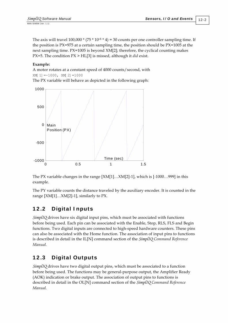
The axis will travel 100,000 * (75 * 10-6 * 4) = 30 counts per one controller sampling time. If the position is PX=975 at a certain sampling time, the position should be PX=1005 at the next sampling time. PX=1005 is beyond XM[2]; therefore, the cyclical counting makes PX=5. The condition PX > HL[3] is missed, although it did exist.
Example: A motor rotates at a constant speed of 4000 counts/second, with XM[1]=-1000, XM[2]=1000 The PX variable will behave as depicted in the following graph:
0 0.5 1 1.5-1000
-500
0
500
1000
Time (sec)
Main Position (PX)
The PX variable changes in the range [XM[1]…XM[2]-1], which is [-1000…999] in this example.
The PY variable counts the distance traveled by the auxiliary encoder. It is counted in the range [XM[1]…XM[2]-1], similarly to PX.
12.2 Digital Inputs
SimplIQ drives have six digital input pins, which must be associated with functions before being used. Each pin can be associated with the Enable, Stop, RLS, FLS and Begin functions. Two digital inputs are connected to high-speed hardware counters. These pins can also be associated with the Home function. The association of input pins to functions is described in detail in the IL[N] command section of the SimplIQ Command Reference Manual.
12.3 Digital Outputs
SimplIQ drives have two digital output pins, which must be associated to a function before being used. The functions may be general-purpose output, the Amplifier Ready (AOK) indication or brake output. The association of output pins to functions is described in detail in the OL[N] command section of the SimplIQ Command Reference Manual.
SimplIQ Software Manual Sensors, I/O and Events MAN-SIMSW (Ver. 1.1)
12-2
12.4 Events and Response Methods
SimplIQ drives identify the following events5:
Change in a GPI (general-purpose digital input)
Change in a limit switch
Change in a Home switch
Change in an Enable switch
Change in a Stop switch
Change in a Begin switch
Encoder Index pulse
In order to identify an event, the event must be defined. From the events in the previous list, only the Index is defined permanently. All other events are programmable. The SimplIQ drive’s six digital connector pins can be routed, with direct or inverted polarity, to functions such as general-purpose digital input or RLS. To learn how to route connector pins to functions, refer to the IL[N] command section of the SimplIQ Command Reference Manual.
Events can be handled at the following speed levels:
Manual query
Periodic query
Automatic routines
Real time (motion management, homing, capture and flag)
12.4.1 Manual Query
The manual query is the simplest method of events handling. By using the IP/IB[N] commands, one can query the state of the input pins and the user-program logics or a host can review the query results. The following table summarizes some of the manual query properties.
Topic Comment
Capture probability Low. Even if a digital input is continuously polled (by communication or by loading a user program), an input pulse may slip away unnoticed between consecutive polls.
Deterministic delay No. Depends on the non-deterministic delays of the Interpreter or the user program management.
Use Non-time-critical queries. Simple operations.
Table 12-2: Manual Query Properties
5 The Harmonica also identifies emergency events such as over-voltage, short-circuit or over-current. The emergency events are explained in Chapter 13.
SimplIQ Software Manual Sensors, I/O and Events MAN-SIMSW (Ver. 1.1)
12-3
12.4.2 Periodic Query
This is possible only in CAN networks. The user can map the digital input word to a synchronous PDO. The host can collect the input state of multiple slaves as a response to a single sync. The following table summarizes some of the periodical query properties.
Topic Comment
Capture probability Low. An input pulse may slip away unnoticed between consecutive syncs.
Deterministic delay Yes. 0.5 milliseconds maximum + CAN network time.
Use CAN networks only. Host logics only.
Table 12-3: Periodic Query Properties
12.4.3 Automatic Routines
Many events can be tied to automatic handler routines in the user program. For more information about automatic user program routines, refer to section 5.8.9. The following table summarizes some of the automatic routine properties.
Topic Comment
Capture probability High. An input pulse may slip away unnoticed only if the user program is not running, the input is masked or the pulse is so short that it does not pass through the input filters.
Deterministic delay No, although in most cases, the automatic routine will start within 2 milliseconds.
Use User program logic.
Table 12-4: Automatic Routine Properties
12.4.4 Real Time: Motion Management, Homing, Capture and Flag
The following can be real-time responses to events:
The motor can stop, or a move in one direction can be prevented (refer to section 11.3 and Chapter 10:).
A new motion can begin (refer to the BG command section of the SimplIQ Command Reference Manual and Chapter 10: of this manual).
The power amplifier can be disabled.
The position counters can be logged.
The value of the position counter can be modified, and the position counter may stop.
An output connector pin can be flagged.
SimplIQ Software Manual Sensors, I/O and Events MAN-SIMSW (Ver. 1.1)
12-4
The following table summarizes some of the real-time properties:
Topic Comment
Capture probability High. An input pulse may slip away unnoticed only if the user program is not running , the input is masked or the pulse is so short that it does not pass through the input filters.
Deterministic delay Yes. Position logging and value setting are immediate and yield accurate results regardless of speed. Position is flagged within 100 microseconds. Motion management functions are responded to at the next controller sampling time.
Use Homing (setting an absolute origin for the incremental position sensors). Motion management. High-speed signaling.
Table 12-5: Real Time Properties
12.5 Homing and Capture
SimplIQ drives use incremental position sensors, which enable it to determine the distance the motor has traveled since power on, but not where the position counting started. The process of determining absolute position is called “homing.”
Homing the main position counter (PX) is typically used for:
Absolute position control in single-feedback position-control mode.
Relative work in single-feedback position-control mode. For example, an axis in a machine may be homed by a sensor for the edge of the product on which the machine is working. The position referencing of the axis becomes relative to the product.
Homing the auxiliary position counter (PY) is typically used for:
Absolute position control in dual-feedback position-control mode.
Relative work in dual-feedback position-control mode.
Fixing the origin of the external position command in single-feedback position-control mode (refer to section 10.2.1).
In the homing process, a trap is set for the event of reaching a desired position. The motor travels until an expected event occurs. The event indicates that the motor is now in a known absolute position, which, if set to the position counter at the time of the event, makes the position reading of the drive absolute.
The expected event may be one of the limited switches (RLS or FLS), the home switch, the encoder index or the digital inputs. However, the capture accuracy depends much more on the homing event selection. If a Home or Index signal is selected as the captured event, the captured position will not miss. If another digital input is selected, the sensing delay for the switch is d=(0.004*TS+IF[N]) milliseconds, and VX*d/1000 counts may be missed.
SimplIQ Software Manual Sensors, I/O and Events MAN-SIMSW (Ver. 1.1)
12-5

Example: TS = 80 Torque controller sampling time, in microseconds IF[1] = 2 Input filter width for digital input #1, in milliseconds VX = 20,000 Motor main speed, in counts/second
When homing on digital input #1, the expected misses are calculated as:
( ) ( ) countIFTSVXmiss 461000
280004.0200001000
]1[004.0=
+⋅⋅=
+⋅⋅=
An event to be captured must first be defined by a proper IL[N] setting. For example, if no digital input is associated with the FLS function, a homing process on FLS will never terminate. Moreover, the FLS function can be undefined during a home search on FLS. The home search will not proceed until FLS is redefined.
12.5.1 Homing Programming
The HM[N] parameters control the main encoder homing process:
HM[3] defines the trigger event: immediate, motor index signal or the change of a digital input.
HM[4] indicates what should happen after the event, in addition to position registration. The command can indicate that the drive should stop immediately or that a digital input should be flagged.
HM[5] defines whether and how to update the main encoder counter: do nothing, set a new value or shift by a specified amount.
HM[1] = 1 arms the homing process (sets the trap for the homing event).
Refer to the HM[N] command section in the SimplIQ Command Reference Manual.
12.5.2 Homing the Auxiliary Encoder
The HY homing function provides additional homing and capture functionality. HY is very similar to HM except that HY refers to the auxiliary Home switch and Index signals rather than the main Home switch and Index. Also, HY can update the value of PY, not PX.
12.5.3 On-the-fly Position Counter Updates
The updating of a position sensor during the homing process has no effect on motion in UM=1, 2 and 3 because these modes do not use position feedback. The effects of a position sensor update (PY in UM=4 and PX in UM=5) by the homing process depend on the mode:
In PTP motions, the remaining motion to target becomes longer or shorter (refer to the following example). If the home correction is made in a constant speed range of the PTP motion, the redesign of the motion path may be hardly visible. This mechanism enables registration and final motion corrections on-the-fly.
SimplIQ Software Manual Sensors, I/O and Events MAN-SIMSW (Ver. 1.1)
12-6

In jog motions, the position command is jumped according to the position feedback, so that the motion is unaffected by the position counter update.
If the software position reference generator stops or has already stopped, the software position command is corrected according to the position feedback. The motion is unaffected by the position counter update.
In PVT or PT motions, an on-the-fly position counter update may lead to an immediate high position error, and the motor may abort with an excessive position tracking error exception.
With UM=5, if the auxiliary encoder counter is modified, and the following is true:
The motor tracks the auxiliary encoder with no ECAM table (RM=1, FR[3] is nonzero and EM[1]=0)
The software position generator is idle, jogging or running PTP the software position reference will be modified so that the motion is not affected. In PTP mode, the PA parameter will change automatically to reflect the modification.
Example: A PTP motion starts with PA=PX=0. After setting PA=1000;BG;, a motion 1000 counts long is expected. If, at PX=500, the position has been reset to zero through homing, there should be 1000 counts remaining immediately after the homing. The total length of the motion becomes 1500.
12.5.4 Example 1: Homing with Home Switch and Index
The following homing algorithm may be used for the very common switch arrangement in Figure 12-1.
Start the motor.
Jog back until RLS.
Jog at forward speed until home.
Look for the next index and set the position there to 0.
Figure 12-1: Sample Switch Locations
The position setting is taken by the index, because in many applications, the index is much more accurate than the Home switch, which is needed for resolving index ambiguity (many index pulses may occur along the path of travel).
In normal operation, the FLS and RLS serve as emergency indicators, and the motor is not expected to reach them. RLS is visited during the homing process, in order to know in which direction to look for the Home switch.
SimplIQ Software Manual Sensors, I/O and Events MAN-SIMSW (Ver. 1.1)
12-7

The following user program performs the algorithm: function [int status] = homing1(int TimeOut) /* Homing routine. Input: TimeOut: Timeout for failure Output: status=1 if o.k., otherwise a negative error code Assumptions: RLS,FLS,HOME already programmed by IL[1],IL[2],IL[3] commands */ int OldMi; /* Go reverse until limit switch */ OldMi=MI;MI=MI|0x16; /* Prevent operational AUTO_RLS routine while in homing process*/ /* Arm homing for ↑RLS, stop after homing, don't initialize counter*/ HM[3]=7;HM[4]=0;HM[5]=2;HM[1]=1; /* Go to the reverse */ JV=-10000;BG;WaitArrive(2000);if(status<=0)goto LastLine; end /* Go until home switch*/ HM[3]=1;HM[4]=2;HM[5]=2;HM[1]=1; JV=-JV;BG;WaitHome(2000);if(status<=0)goto LastLine; end /* Finallyset position by index */ HM[3]=3;HM[4]=0;HM[5]=0;HM[1]=1; WaitHome(2000);if(status<=0)goto LastLine; end status=1;/*Success return */ ##LastLine MI=OldMI; ** Restore AUTO_RLS routine status return
Note that this function uses MI to prevent RLS and Home from activating the AUTO_RLS and AUTO_HM routines, respectively. Another possible approach would be to use IL[N] to change the functionality of the switch to GPI (general-purpose input) and then home on the GPI. However, with the latter approach, the programmer must know which connector pin is programmed as RLS.
The following auxiliary functions were used with the algorithm: function [int status]=WaitArrive(int TimeOut) /* Wait until MS=0, or until too much time elapses */ int StartTime ; status = -1; StartTime = TM; while (MS) if ( tdif(handle) >= TimeOut) return ; end end status = 1 ;
SimplIQ Software Manual Sensors, I/O and Events MAN-SIMSW (Ver. 1.1)
12-8

return function [int status]=WaitHome(int TimeOut) /* Wait until HM=0, or until too much time elapses */ int StartTime ; status = -1; StartTime = TM; while (HM) if ( tdif(handle) >= TimeOut) return ; end end status = 1 ; return ##ErrorOut /* Error handler – just exit*/ return
12.5.5 Example: Double Homing Corrects Backlash Offsets
This example demonstrates homing on the Home switch without using the Index. In many gear systems, the Index signal cannot be used for homing because:
Motor or gear repairs may not require tuning of the index position or the drive.
Backlash and gear compliance prevent accurate mapping of the motor position to the load.
In order to prevent compliance and timing errors, the position of the Home switch is captured two times, with alternating movement directions. The two captured results are averaged in order to cancel the error sources.
If PX=10,000 is in the middle of the Home switch, the homing formula is: PX=PX+10,000 -0.5 * (PX at right home edge + PX at left home edge)
The following user program executes this routine, using the auxiliary functions of the previous example: function [int status] = homing1(int TimeOut) /* Homing routine. Input: TimeOut: Timeout for failure Output: status=1 if o.k., otherwise a negative error code Assumptions: RLS,FLS,HOME already programmed by IL[1],IL[2],IL[3] commands */ int OldMi,Pos1; /* Go reverse until limit switch */
SimplIQ Software Manual Sensors, I/O and Events MAN-SIMSW (Ver. 1.1)
12-9

OldMi=MI;MI=MI|0x16; /* Prevent operational AUTO_RLS routine while in homing process*/ /* Arm homing for ↑RLS, stop after homing, don't initialize counter*/ HM[3]=7;HM[4]=0;HM[5]=2;HM[1]=1; /* Go to the reverse */ JV=-10000;BG;WaitArrive(2000);if(status<=0)goto LastLine; end /* Go until falling home switch, stop, and capture position*/ HM[3]=2;HM[4]=0;HM[5]=2;HM[1]=1; JV=-JV;BG;WaitHome(2000);if(status<=0)goto LastLine; end Pos1=HM(7) /* Sample home switch from other side */ HM[1]=1; JV=-JV;BG;WaitHome(2000);if(status<=0)goto LastLine; end /* Final calculation – set immediate difference correction to PX*/ HM[2]=10000-(HM[7]+Pos1)/2;HM[3]=0;HM[4]=2;HM[5]=1;HM[1]=1; status=1;/*Success return */ ##LastLine MI=OldMI; ** Restore AUTO_RLS routine status return
12.5.6 Capture
Capture is a special case of homing, in which the event is programmed to register only the counter values, without affecting motion and without updating the position counters. It efficiently synchronizes the motion origin with objects in the working space.
The drive can capture two events defined by the HX and HY commands, and register occurrences of PX and PY of each event. The capture function captures both the main and auxiliary position counters simultaneously, which is useful for synchronizing the main and auxiliary positions. When main capture mode (HM[1]) is required, HM[7] and HM[8] capture PX and PY respectively. When auxiliary capture mode (HY[1]) is required, YM[7] and YM[8] capture PX and PY respectively.
SimplIQ Software Manual Sensors, I/O and Events MAN-SIMSW (Ver. 1.1)
12-10

Chapter 13: Limits, Protections, Faults and Diagnosis
This chapter describes the limits and protections implemented by SimplIQ drives. Limits are software restrictions that prevent SimplIQ drives from running into dangerous situations. For example: Limits set for the torque command prevent the motor or SimplIQ drive from burning.
Reaction to limit switches stops the motor before it accidentally hits something out of its expected motion range.
Protections prevent the motor from starting, or shut down an active motor due to abnormal situations. For example:
Bad or inconsistent setup data prevents the motor from starting. An unexpectedly high motor current can endanger the SimplIQ drive and the motor.
Such a high current is abnormal because the command to the current (torque) amplifier is limited. If the current controller seems to be functioning poorly, the drive is immediately shut down.
The drive is too hot.
When the drive shuts down due to a protection, the motor continues to run on its own inertia unless brakes are used (see section 13.6). In order to avoid spurious motor shutdowns, always:
Leave enough space between the limits and the protection. For example, HL[2] specifies the over-speed limit. A protection is activated when VX > HL[2]. VH[2] specifies the legal command to the speed controller. Speed commands over VH[2] are clipped to VH[2]. The protection HL[2] must be greater than the limit VL[2]. Moreover, the distance HL[2] -VH[2] must leave enough space for the expected speed overshoot.
When safety is a concern, always use brakes. SimplIQ drives can program one of their digital outputs to activate a brake immediately upon motor shutdown.
If an exception stops the motor or prevents the motor from starting, the SimplIQ drive, in most cases, can identify the cause of the event. If a real-time exception reaction is desired, a #@AUTO_ER routine can be added to the user program (see section 5.8.9).
The following commands are used with limits and protections:
Command Description
BP[N] Brake parameters.
CD Dumps the process status of the SimplIQ drive and reports database inconsistencies.
CL[N[ Continuous current limit and “Motor not moving” protection.
EC Error code describing why previous command returned an error.
SimplIQ Software Manual MAN-SIMSW (Ver. 1.1)
13-1

Command Description
ER[N] Tracking error exception limits for speed and position.
HL[N] Protection high limits for position and speed feedback.
IL[N] Input logic. Defines digital inputs as stop and limit switches.
LC Limit current indication that indicates whether peak limit is active.
LL[N] Protection low limits for position and speed feedback.
MF States reason for a motor automatic shutdown.
OL[N] Output logic. Programs digital outputs as brake activation or as drive ready indication.
PL[N] Peak current limit.
PS Program status.
SR Status register. Gives SimplIQ drive status, including if motor is shut down by exception or if a Stop switch has been hit.
VH[N] Command high limits for position and speed reference.
VL[N] Command low limits for position and speed reference.
Figure 13-1: Commands Relevant to Limits, Protection and Diagnosis
CANopen offers an additional protection level: emergency objects issued in cases of errors or applied protections (refer to the Elmo CANopen Implementation Manual).
13.1 Current Limiting
The drive protects the motor from over-current using a two-stage method. The motor maximum peak current (given by PL[1]) is available for the peak duration time (specified by PL[2]), while for longer periods, the current is limited to its continuous limit (CL[1]).
The current limiting process is dynamic: If the current has been close to its continuous limit, the time allowed for the peak current is reduced. This process is determined as follows:
The absolute value of the measured motor current (in vector servo drives, this is 22DQ II +
) is applied to a first order low-pass filter. The state of the filter is compared with two thresholds. When the state of the filter is higher than the upper threshold, the continuous limit is activated. When the state of the filter is lower than the bottom threshold, the peak limit is activated.
The time constant of the low-pass filter is
⎥⎦⎤
⎢⎣⎡ −
−=
MCCL
PL]1[1log
]2[τ
where MC is the maximum servo drive current.
SimplIQ Software Manual Limits, Protections, Faults and Diagnosis MAN-SIMSW (Ver. 1.1)
13-2

The maximum time for which the peak current can be maintained after the current demand has been zero for a long time is:
τ⋅⎥⎦
⎤⎢⎣
⎡−
]1[]1[1log
PLCL
seconds.
If PL[1] = MC, the maximum time allowed for peak current is PL[2]. Otherwise, the servo drive can provide the peak current for a longer time.
Generally, if a current demand of PL[1] has been placed after the current command is stable at I1 < CL[1] for a long time, peak current PL[1] will be available for:
τ⋅⎥⎦
⎤⎢⎣
⎡ −−−
]1[1]1[1log
PLICL
seconds.
The resolution of PL[1] is approximately MC/1000, and the resolution of PL[2] is approximately 0.1 second.
Example: The following graph depicts the signals related to the current command limiting process for MC=6, PL[1]=6, PL[2]=3 and CL[1]=3.
0 1 2 3 4 5 6 7 8 90
1
2
3
4
5
6
Application current demand motor currentcommand
Filter state
LC current limitIndication
The application motor current command increases from 0 to 6 amperes at the time of 0 seconds, and then decreases to 0 at the time of 5 seconds.
The state of the filter increases until it reaches the continuous current limit of 3 at the time of 3 seconds. At that time, the LC flag is raised and the motor current command decreases to CL[1] -= amperes.
After the motor current command is set to zero, the state of the filter begins to drop. When it drops to 2.7 amperes = 90% of 3 amperes, the LC flag is reset and the torque command limiting returns to 6 amperes.
SimplIQ Software Manual Limits, Protections, Faults and Diagnosis MAN-SIMSW (Ver. 1.1)
13-3

13.2 Speed Protection
The reference to the speed controller is limited to the range [VL[2]…VH[2]]. The limiting (applied on the total of the software reference and external reference) is made by the stop manager.
In addition to the speed limiting, the SimplIQ drive provides two forms of speed protection:
Speed-following error protection (ER[2])
Over-speed limit protection (HL[2]/LL[2])
The first protection detects an over-speed error. The ER[2] parameter specifies the limit for the velocity error. If the absolute value of the speed tracking error VE exceeds ER[2], the SimplIQ drive issues the exception MF=0x80 and the motor is shut down automatically.
The second protection detects over-speed. If VX is greater than HL[2] or less than LL[2], the SimplIQ drive issues the exception MF=0x20,000 and the motor is shut down automatically.
The over-speed protection is active in all unit modes. The speed for over-speed detection is always derived from the main position sensor; this means that in dual-loop systems (UM=4), the motor speed (the inner loop) — and not the load speed (the outer loop) — is over-speed protected.
The speed command and feedback limits are illustrated in the following figure. The drive normally operates in the area marked “Within command and feedback limits.” However, it may, momentarily, visit areas marked “Overshoot area” due to overshoot, and this is acceptable. If the speed feedback reaches the “Abort area,” the drive will issue an over-speed exception and the motor will be shut down automatically.
0
W ith in speed com m and and feedback lim its
VL[2] VH[2]
LL[2] HL[2]
W ith in speed feedback lim its, out o f com m and lim its. Abort
Area Abort Area
O ver- shoot Area
O ver- shoot Area
Figure 13-2: Speed Command and Feedback Limits
Remember that when the drive shuts down due to an exception, the motor continues to run on its own inertia unless brakes are used (refer to section 13.6).
SimplIQ Software Manual Limits, Protections, Faults and Diagnosis MAN-SIMSW (Ver. 1.1)
13-4

13.6).
SimplIQ Software Manual Limits, Protections, Faults and Diagnosis MAN-SIMSW (Ver. 1.1)
13-5

In order to avoid spurious motor shutdowns, always:
Specify the largest ER[2] that can be tolerated.
Leave large enough space between VH[2] and HL[2], and between VL[2] and LL[2], to allow for speed overshoots.
13.3 Position Protection
SimplIQ drives provides two forms of position protections:
Position-following-error protection (ER[3])
Out-of-position-range protection (HL[3]/LL[3])
The first protection detects an error of too large a position. The ER[3] parameter specifies the limit for the position error. If the absolute value of the tracking error PE exceeds ER[3], the SimplIQ drive issues the exception MF=0x100 and the motor is shut down automatically.
The second protection detects a motor position that is out of range. If the position feedback (PX in UM=4 and PY in UM=5) is greater than HL[3], or less than LL[3], the SimplIQ drive issues the exception MF=0x400,000 and the motor is shut down automatically.
Position reference and feedback limits should not be placed too close to position counter limits because there, the relations “greater than” and “smaller than” are not well defined (see section 12.1).
ER[3] is limited to the modulo counting range (described fully in the ER[3], XM[N] and YM[N] command sections in the SimplIQ Command Reference Manual).
The following table lists the effects of the position limits on the different unit modes:
Unit Mode Results
UM=1 No position limiting
UM=2 No position limiting
UM=3 No position limiting
UM=4 Position control by an auxiliary sensor
UM=5 Position control by a main sensor
Table 13-1: Effects of Position Limits on Unit Modes
The position command and feedback limits are illustrated in the following figure.
The drive normally operates in the area marked “Within command and feedback limits.” However, it may momentarily visit the areas marked “Overshoot area” due to an overshoot, which is acceptable. If the position feedback reaches the “Abort area” the drive will issue an out-of-position-range exception and automatically shut down.
SimplIQ Software Manual Limits, Protections, Faults and Diagnosis MAN-SIMSW (Ver. 1.1)
13-6

0
W ith in position com m and and feedback lim its
VL[3] VH[3]
LL[3] HL[3]
Position w ith in feedback lim its, out o f com m and lim its Abort
Area Abort Area
O ver-shootArea
O ver- shoot Area
Figure 13-3: Position Command and Feedback Limits
Remember that when the drive shuts down due to an exception, the motor will continue to run on its own inertia unless brakes are used (refer to section 13.6).
In order to avoid spurious motor shutdowns, always:
Specify the largest ER[3] that can be tolerated.
Leave large enough space between VH[3] and HL[3], and between VL[3] and LL[3], to allow for speed overshoots.
13.4 Enable Switch
One of the digital inputs can be programmed as an “Inhibit; digital input programming is described in detail in the IL command section of the SimplIQ Command Reference Manual.
When an Inhibit input is active:
If the motor is off, MO=1 will not start the motor.
If the motor is on, MO=0 is set immediately. If the motor is rotating at high speed, the inhibit function may be unsafe, because the motor may continue to run uncontrolled on its own inertia.
When an Inhibit input is inactive, MO=1 will start the motor if the motor is off.
For safety reasons, it is recommended to program the Inhibit function as “active low” in order to prevent accidental motor starts when the input pin is disconnected, or when its driving source is powered down.
SimplIQ Software Manual Limits, Protections, Faults and Diagnosis MAN-SIMSW (Ver. 1.1)
13-7

13.5 Limit Switches
SimplIQ drives have six digital input pins, each of which may be associated with a different function. A pin may function as a general-purpose input or it can function as a motion limiter.
As a motion limiter, a digital input can stop the motion via the stop manager, stop the reference generator or limit the motion to a single direction. In addition to stopping the motion, the digital input can activate an automatic routine in the user program.
For more information about the functions associated with input pins, refer to the IL[N] command section in the SimplIQ Command Reference Manual.
13.6 Connecting an External Brake
Connecting an electrical brake to a motor enhances safety in cases where:
The load is unbalanced and moves by its own weight when the motor is off.
Motor freewheeling cannot be tolerated in malfunction situations.
Extreme motor deceleration is required in response to an emergency event.
The brake activation must be synchronized to the motor-on / motor-off process because:
The motor may “run away” if the brake is engaged for too long a time after MO=0,
The position controller may integrate a position error that existed when the brake was released after the motor was turned on. When the brake is completely released, the motor may jump.
SimplIQ drives can program a digital output as a “brake” output (refer to the OL[N] command section in the SimplIQ Command Reference Manual). The brake output must be connected as follows:
DC
HarmonicaOutput
opto-coupler
Brake relay - NormallyEngaged
Connectorpins
Figure 13-4: Brake Output Connection
The brake must be engaged when no current is in the brake coil.
The brake relay coil must be equipped with a freewheeling diode. For the current and voltage ratings of the SimplIQ drive connector pins, consult the
Harmonica, Bassoon or Cello Installation Guide.
SimplIQ Software Manual Limits, Protections, Faults and Diagnosis MAN-SIMSW (Ver. 1.1)
13-8

The normal waveforms for brake activation are as follows:
Figure 13-5: Normal Brake Activation Timing
At the brake activation times (BP[2] milliseconds to disengage and BP[1] milliseconds to engage), the motor is controlled to a complete stop.
If MO=0 is set automatically by an exception, the brake is activated immediately, without any delay.
13.7 When the Motor Fails to Start
The main reasons for failure when starting a motor are:
The physical conditions are not right.
The database is not consistent (refer to section 13.9.2)
The following physical conditions are checked before voltage is applied to the motor:
Power supply under-voltage
Power supply over-voltage
Drive temperature too high
Motor not connected to servo drive
An active limit switch is programmed to shut down the servo drive
SimplIQ Software Manual Limits, Protections, Faults and Diagnosis MAN-SIMSW (Ver. 1.1)
13-9

The motor will not start if the voltage of the power supply is not within range, if the servo drive temperature is too high, or if an active switch prevents motor on. The MO command returns error code 65 or 66. The failure reason may be read through the status (SR command) report. If the voltage is in range and the temperature is not excessive, the drive will attempt to start the motor.
13.8 Motion Faults
Error conditions may cause the drive to automatically shut down the motor, at which time:
The MO variable is set to zero.
The MF variable is set to reflect the reason for shutdown.
A flag in the status register (SR command) indicates that the motion has been aborted.
The next “Motor enable” (MO=1) is permitted after 150 sample times (TS).
The MF variable may reveal the reason for motor shutdown even if the reason no longer exists. For example, if the power supply has too large an impedance, its voltage may drop in full load and the servo drive will be automatically shut down due to under-voltage. When the motor is shut down, the under-voltage disappears. On the other hand, if an over-voltage is generated due to an insufficient shunt, the over-voltage will disappear when the motor is shut down.
The over- or under-voltage conditions that caused the fault are captured in the MF variable.
Notes: MF is reset automatically every “Motor enable” (MO=1) when the fault is no
longer valid.
The SR variable also reports motor faults, according to the current status of the drive/motor. When the fault is no longer valid, the indication is removed. For example, if an “Over-voltage” occurs, SP indicates the fault and MF latches the fault indication. As soon as the over-voltage conditions end, the fault indication is removed from SR. The “Fault latch” indication in the SR remains set (bit 6) and MF indicates “Over-voltage” until the next MO=1.
When the drive shuts down by exception, the motor continues to run on its own inertia unless brakes are used (refer to section 13.6).
A drive exception shutdown can be captured and reacted to by placing an AUTO_ER routine in the user program.
For a full list of the exceptions that can cause automatic shutdown, refer to the MF command section in the SimplIQ Command Reference Manual.
SimplIQ Software Manual Limits, Protections, Faults and Diagnosis MAN-SIMSW (Ver. 1.1)
13-10

13.9 Diagnosis
13.9.1 Monitoring Motion Faults
Motion faults can be monitored by:
Continuously polling the drive status
Observing “AOK” digital outputs
Trapping CAN emergency objects
13.9.1.1 Polling the Drive Status
The drive can be polled using the SR command, which reports a bit-field that fully describes the drive activity. One of the SR bits reports the existence of motion fault, while another SR bit reports the existence of a user program fault.
When a motor fault is detected, the MF command reports the exact reason for the fault; when a run-time program fault is detected, the PS command reports -1. The reason for the fault is reported by the Elmo Studio and by analyzing the DB_ES command.
For full explanations, refer to the relevant command section in the SimplIQ Command Reference Manual and to Chapter 4 of the Composer for SimplIQ Servo Drive User Manual.
13.9.1.2 Observing AOK
One of the digital outputs may be programmed to indicate that the drive is ready and that therefore, no physical reason — such as over-temperature, over-voltage or under-voltage — is preventing the drive from working. The AOK output reports the physical operating conditions, but it does not indicate all motor faults. In order to program an output for motor fault indications, the AUTO_ER routine should be used (see section 12.4.3.
13.9.2 Inconsistent Setup Data
The setup data is checked when loading the setup from the parameter non-volatile flash storage, and before starting the motor. When the setup parameters are retrieved from flash storage (at power-on or by an LD command), they are thoroughly checked for legality and consistency. If the parameters are found to be illegal or inconsistent, the drive resets to its factory defaults. The source of the problem can be found using the CD command (described in this section) and the contents of the flash storage can be corrected using the application editor.
Loading the setup parameters form the flash memory rarely fails, because the parameters are checked before allowing non-voltage storage. The only reason for failure is generally a major firmware revision upgrade.
SimplIQ Software Manual Limits, Protections, Faults and Diagnosis MAN-SIMSW (Ver. 1.1)
13-11

Before enabling the motor, the drive tests all parameters to ensure that they are sensible. For example, the variables CA[4], CA[5] and CA[6] define how the Hall sensors are ordered. If CA[4] equals CA[5], two Hall sensors are assigned to the same position, which is illogical. If CA[4] = CA[5], the command MO=1 will fail and will return the error code 54 to indicate a bad database. In order to determine the reason for this type of failure, use the CD command, which will return: Null address=0 Failure address=0 Called Handler=none Database status: CA[4], error code=37
The first lines establish that the CPU did not detect an exception (refer to following section). The last line states that parameter CA[4] yielded the error code 37, meaning that two Hall sensors are defined for the same place.
13.9.3 Device Failures and CPU Dump
Programming bugs or errors may lead to CPU exceptions, such as an attempt to divide by zero or to access a variable that does not exist. Programming errors may also lead to CPU overloading, in which case the CPU is not able to complete its control tasks on time and thereby causes the CPU stack to overflow.
For this reason, SimplIQ drives use traps for CPU exceptions and stack overflow. When it traps an exception, it:
Shuts off all controller activity and aborts any motion to freewheeling
Writes down the exact trap that was activated, along with the address in the firmware that caused the exception
After the exception, the communication remains enabled so that the drive can be queried about the event. The motor, however, cannot be set to work again until the drive is rebooted.
A CPU exception is detected using the CD and SR commands. The SR command indicates only that an exception occurred, while the CD (CPU dump) command provides the details. The CD command provides the report as follows:
Null Address Code Address in Firmware in which Exception Occurred (0 if OK)
Failure address
Code address in firmware when stack overflow has been detected (0 if OK)
Called handler A string describing the type of exception: A divide-by-zero attempt An attempt to access a non-existing variable Many other possible exceptions
This string is “none” if no exception was trapped.
Table 13-2: CD Reported Elements
The CPU dump also returns the database status, as described previously.
SimplIQ Software Manual Limits, Protections, Faults and Diagnosis MAN-SIMSW (Ver. 1.1)
13-12

13.10 Sensor Faults
13.10.1 Motor Cannot Move
When the motor is unable to complete a command to move, the reasons may be:
The motion sensor is faulty: The motor moves but motion is not detected. In this case, AC motors will generally stop, because the stator field will remain stationary.
The motor is faulty or another mechanical failure is preventing the motor from moving.
The controller filter is poorly tuned. In this case, the motor torque may oscillate wildly at high frequency, but the motor will barely move.
Indications of such situations include:
High average motor torque
Stationary motor or very slow motor movement
A stationary motor responding to a high torque command does not always indicate an error. In certain applications, such as thread fastening, it is perfectly legitimate for the motor to reach a mechanical motion limit.
The drive user should define whether a high-torque stopped motor is a fault or not. If the parameter CL[2] is less than 2, a high torque that does not lead to motion is not considered a fault. If the parameter CL[2] is 2 or more, a high-torque stopped motor, detected for at least 3 continuous seconds, is considered a fault. The motor is set to off (MO=0) and MF=0x200,000. The time constant of 3 seconds is used because almost every motion system applies high torques for short acceleration periods while the speed is slow.
CL[2] defines the tested torque level as a percentage of the continuous current limit CL[1]. CL[3] states the absolute threshold main sensor speed under which the motor is considered not moving. CL[3] should not be set to a very small number because when a motor is stuck, a vibration may develop that will induce speed-reading. When an encoder wire is damaged, the motor will run away with the encoder readout vibrating + bit. This also creates speed-reading.
Example: If CL[2]=50 and CL[3]=500, the drive will abort (reset to MO=0) if the torque level is kept at at least 50% of the continuous current, while the shaft speed does not exceed 500 counts/second for a continuous 3 seconds.
SimplIQ Software Manual Limits, Protections, Faults and Diagnosis MAN-SIMSW (Ver. 1.1)
13-13

13.11 Commutation is Lost
The drive uses the feedback (encoder) counts to calculate the electric angle of the rotor. This calculation is used to set the currents at the stator so that the magnetic field of the stator points 90º away from the rotor. The angle between the magnetic field in the stator and rotor is called the “commutation angle”. The motor torque is:
)sin(IKe23T rs θ−θ⋅⋅=
where: T is the torque. Ke is the motor constant. I is the motor current.
sθ is the stator field angle.
rθ is the rotor angle.
The difference rs θ−θ=θ is called the commutation angle. Obviously, θ must be maintained near 90º for the motor to function properly. If the commutation angle is set incorrectly, the motor will lose torque. For a given torque command (given either directly in UM=1 or by external control loops in other modes), the motor current remains the same. The torque falls because the proportion between the current and the torque is cos(∆θ), where ∆θ is the commutation angle error.
Note that in extreme cases, where abs(∆θ) > 90º, the motor torque becomes reversed with respect to what is expected by the current defined in the command.
13.11.1 Reasons for and Effects of Incorrect Commutation
Commutation errors may be disastrous to drive operation. The most common incorrect commutation behaviors are:
The commutation error is static (that is, ∆θ does not change in time) Static commutation errors occur due to bad setup data or due to an exceptional load in automatic alignment (at MO=1, when the only available sensor is an incremental encoder). A static commutation error leads to motor torque reduction, reduced efficiency, degraded dynamic response and possible speed or position loop instability.
The commutation is static (that is, θs does not change as a function of the motor position) Static commutation occurs in encoder systems when an encoder wire is broken. In this situation, the direction of the stator field is constant and, at the torque command, the rotor seeks equilibrium aligned to the magnetic field. If the motor is driven by an external speed or position controller, it will receive a full-torque command and dissipate the corresponding heat, without generating any motion.
SimplIQ Software Manual Limits, Protections, Faults and Diagnosis MAN-SIMSW (Ver. 1.1)
13-14

The commutation is drifting (that is, ∆θ changes in time) drift can occur in two forms:
Slow drift, caused by excessive noise on the encoder lines, a damaged or dirty encoder or a wrong encoder resolution setting. Usually, ∆θ drifts slowly and, when the motor stops, it does not drift at all. Slow drifting causes the motor to lose torque gradually until fully stopped at the static setting of ∆θ = +90º. At this point, the current in the motor will not produce any torque. The motor will overheat, but it will not move.
Fast drift, which can be caused by an encoder frequency reaching the encoder filter value (EF[1] command). The drive does not sense any feedback, causing a sudden stop and a rise in current with no torque. ∆θ drifts to 0 because the rotor angle aligns with the field angle.
13.11.2 Detection of Commutation Feedback Faults
Commutation faults can be detected if there are two sources of commutation data. The redundant data enables a failure of one sensor to be identified by the other.
The SimplIQ drive supports commutation failure identification through the use of redundant encoder and digital Hall sensor data. The Hall sensors provide a rough, but direct, estimate of the commutation angle. The encoder provides high-resolution data, but it may accumulate errors if the drive setup data is set incorrectly or if it is faulty. If the encoder’s cumulative commutation angle differs by more than 15 electrical degrees from the closest value to match the Hall sensor reading, an error is issued. The motor is shut down (MO=0) and MF is set to 0x4. An error is issued when there is a commutation discrepancy of between 15 and 45 degrees.
After detection of a commutation fault, the motor must be shut down and a proper MF code set to be active. The motor cannot be stopped under control, because the correlation between the motor currents and the resulting torque is not known. At the next motor startup attempt, the motor will again seek commutation.
SimplIQ Software Manual Limits, Protections, Faults and Diagnosis MAN-SIMSW (Ver. 1.1)
13-15

Chapter 14: Filters
The filter serves as a basic building block for the SimplIQ drive algorithms. The SimplIQ drive uses a filter mechanism in the following:
The speed controller high-order filter, which is a control filter placed between the speed PI controller and the torque controller (see Chapter 15)
The position controller high-order filter, a control filter placed between the position controller gain and the speed PI controller (see Chapter 15)
The analog reference signal to the speed controller, which can be filtered
Analog position sensors (potentiometer and analog encoder), in which a filter smoothes the position and speed measurements
All of these filters are parameterized the same way. Each filter is built by one or more second-order links, connected in a series, as depicted in the following two-block example:
In the top frame, the first block in the series is a second-order low-pass filter; the next one is a notch filter. The bottom frame contains a fourth-order filter resulting from applying the notch filter in series with the low-pass filter.
A first-order filter link can be made by setting some of the second-order filter parameters to zero. The filters are implemented in a normalized form, meaning that the DC gain of each filter (and of the entire filter series) is 1.0.
Very high-order control filters can be used with the SimplIQ drive. However, when they are used, the filter implementation increases the load on the CPU significantly and may require an increase in the sampling time (TS) (see section 7.3).
The parameters of all filters are programmed into the vector KV[N], as follows:
101
102
103
104
10-4
10-3
10-2
10-1
100
101
101
102
103
104
10-0.8
10-0.7
10-0.6
10-0.5
10-0.4
10-0.3
10-0.2
10-0.1
1 2 3 410-4
10-3
10-2
10-1
100
In
Out
Ot
In
Two links in series
4th order equivalent
SimplIQ Software Manual MAN-SIMSW (Ver. 1.1)
14-1

Filter Parameters Maximum Order
Speed controller high-order filter KV[0]…KV[47]
Position controller high-order filter KV[48]…KV[75]
Analog position sensor filter KV[76]…KV[87] Order 4 (2 blocks)
Analog reference to speed controller KV[88]…KV[99] Order 4 (2 blocks
Table 14-1: KV[N] Filter Parameters
The high-order filter parameters of the speed controller are as follows:
Parameter Description Value Range
KV[0] Is filter active? 0: Filter not active and bypassed. All other filter parameters ignored. 100: Filter is active.
KV[1] Last index in KV[N] used for this filter
1+5n, where 1 ≤ n ≤ 9 is the number of used second-order links. The maximum resulting filter order is 18.
KV[2]…KV[6] Parameters of first link
KV[7]…KV[11] Parameters of second link
KV[12]…KV[16] Parameters of third link
KV[17]…KV[21] Parameters of fourth link
KV[22]…KV[26] Parameters of fifth link
KV[27]…KV[31] Parameters of sixth link
KV[32]…KV[36] Parameters of seventh link
KV[37]…KV[41] Parameters of eighth link
KV[42]…KV[47] Parameters of ninth link
Table 14-2: Speed Controller High-order Filter Parameters
The high-order filter parameters of the position controller are as follows:
Parameter Description Value Range
KV[48] Is filter active? 0: Filter not active and bypassed. All other filter parameters ignored. 100: Filter is active.
KV[49] Last index in KV[N] used for this filter
49+5n, where 1 ≤ n ≤ 5 is the number of used second-order links. The maximum resulting filter order is 10.
KV[50]…KV[54] Parameters of first link
KV[55]…KV[59] Parameters of second link
KV[60]…KV[64] Parameters of third link
SimplIQ Software Manual Filters MAN-SIMSW (Ver. 1.1)
14-2

Parameter Description Value Range
KV[65]…KV[69] Parameters of fourth link
KV[70]…KV[74] Parameters of fifth link
Table 14-3: Position Controller High-order Filter Parameters
The sensor filter parameters are:
Parameter Description Value Range
KV[75] Is filter active? 0: Filter not active and bypassed. All other filter parameters are ignored. 100: Filter is active.
KV[76] Last index in KV[N] used for this filter
76+5n, where 1 ≤ n ≤ 2 is the number of used second-order links. The maximum resulting filter order is 4.
KV[77]…KV[81] Parameters of first link
KV[82]…KV[86] Parameters of second link
Table 14-4: Sensor Filter Parameters
The parameters of the analog speed reference filter are:
Parameter Description Value Range
KV[87] Is filter active? 0: Filter not active and bypassed. All other filter parameters are ignored. 100: Filter is active.
KV[88] Last index in KV[N] used for this filter
88+5n, where 1 ≤ n ≤ 2 is the number of used second-order links. The maximum resulting filter order is 4.
KV[89]…KV[93] Parameters of first link
KV[94]…KV[99] Parameters of second link
Table 14-5: Analog Speed Reference Filter Parameters
SimplIQ Software Manual Filters MAN-SIMSW (Ver. 1.1)
14-3

14.1 Internal Structure of a Filter Link
There are two types of filter links:
Type 16, a fixed link for which the next four link parameters are the filter coefficients.
Type 26, a scheduled link, for which the next four link parameters are not used. The four filter coefficients are selected at run-time from the filter bank.
A filter link has five parameters:
Element Description Comment
0 Type 16 for fixed links 24 for scheduled links
1…4 Filter coefficients k1, k2, k3 and k4 Used only for fixed blocks
The parameters k1, k2, k3 and k4 are stored inside the SimplIQ drive as integers. As a result, when you read back these coefficients, they may have slightly different values than those that you programmed.
14.1.1 Fixed Link (Type 16)
The basic continuous-time second-order element is a filter with a unity DC gain:
DCsEsBAsEs
BD
2
2
++++
⋅
Note that this element is very general: It can be used, for example, as a notch filter, a low-pass complex pole filter, a double-lead element or a single pole.
The equivalent discrete form is:
212
212
0
azazbzbzb
++++
Order Parameter Description Comment
1 k1 b0 + b1 + b2 Float, represented by a long value
2 k2 -(b1 + b2) Float, represented by a long value
3 k3 -b2 Float, represented by a long value
4 k4 a2 Float, represented by a long value
Table 14-6: Fixed Link Parameters
The parameter a1 is obtained explicitly by a1 = b1 + b1 + b1 - a1 - 1.
SimplIQ Software Manual Filters MAN-SIMSW (Ver. 1.1)
14-4

14.1.2 Scheduled Link (Type 26)
Only one block of this type can be used.
The basic continuous-time second-order element is the unity DC gain filter:
)()()()()()(
)()(
2
2
kDskCskEkBskAskE
kBkD
++++
⋅
The index k is the gain scheduler selector: It selects one set of (A, B, C, D, E) from the 63 possible selections [A(1), B(1), C(1), D(1), E(1)…A(63), B(63), C(63), D(63), E(63)].
The discrete equivalent form is similar to that of the unscheduled block:
)()()()()(
212
212
0
kazkazkbzkbzkb
++++
Order Parameter Description Comment
1 k1 (k) b0(k) + b1(k) + b2(k) Float, represented by a long value
2 k2 (k) -(b1(k) + b2(k)) Float, represented by a long value
3 k3 (k) -b2(k) Float, represented by a long value
4 k4 (k) a2(k) Float, represented by a long value
Table 14-7: Scheduled Link Parameters
The DC gain of this block is unity.
For more details about gain scheduling, refer to section 15.3.
14.2 Examples of Filter Implementation
The following examples illustrate how the more common filter links can be implemented. Each example calculates the parameters b0, b1, b2, a1 and a2. Use Table 14-6 to convert them to k1, k2, k3 and k4.
Note that the frequency response of a discrete-time filter depends on the sampling time. In the following examples, you should use sampling time T.
Filter Sampling Time Comment
Speed controller high-order filter WS[28] x 10-6 Speed controller sampling time
Position controller high-order filter
WS[55] x 10-6 Position controller sampling time
Analog position sensor filter WS[55] x 10-6 Position controller sampling time
Analog reference to speed controller
WS[28] x 10-6 Speed controller sampling time
SimplIQ Software Manual Filters MAN-SIMSW (Ver. 1.1)
14-5

14.2.1 Low-pass (Complex Pole) Element (Represented by Second-order Block)
The basic continuous-time complex pole element is:
22
2
2 ωωω
+⋅⋅⋅+ sds
where:
f⋅= πω 2 is the angular frequency.
f [Hz] is the pole frequency.
The discrete equivalent form is:
212
0
azazzb++
where:
2
2
22
1 44
82
ωω
ω
++
−=
TTd
Ta
2
2
22
2 44
44
ωω
ωω
++
−+=
TTd
Td
Ta
2
2
2
210 4441
ωωω
++=++=
TTd
aab
14.2.2 Notch Filter Element (Represented by Second-order Block)
The basic continuous-time notch filter element is:
2222
2
2111
2
21
22
22
ωωωω
ωω
+⋅⋅⋅++⋅⋅⋅+
sdssds
where:
ω1 = 2π · f1, and f1 [Hz] is the notch frequency.
ω2 = 2π · f2, and f2 [Hz] is the notch frequency.
d1 is the notch damping.
d2 is the double-pole damping.
SimplIQ Software Manual Filters MAN-SIMSW (Ver. 1.1)
14-6

The discrete equivalent form is:
212
212
0
azazbzbzb
++++
where:
qcp
b111
0++
= , q
pb
)1(2 11
−= ,
qcp
b111
2+−
= ,qcp
a122
2+−
=
q
pabbba
)1(21 2
22101−
=−−++=
assuming:
⎟⎠⎞
⎜⎝⎛
=
2tan
2T
dc
k
kk ω
, 2
2tan
1
⎟⎠⎞
⎜⎝⎛
=T
pk
kω
, ( 2,1=k )
122 ++= cpq
14.2.3 Double-lead Element (Represented by Second-order Block)
The basic continuous-time double lead-lag element is: 2
⎟⎠⎞
⎜⎝⎛
++
⋅bsas
ab
The frequency a / (2π) [Hz] is the lead corner frequency. The frequency b / (2π) [Hz] isis the lag corner frequency.
The discrete equivalent form is: 2
-z)-z(1G)-(1 G ⎟⎟⎠
⎞⎜⎜⎝
⎛⎟⎟⎠
⎞⎜⎜⎝
⎛+
ββ
Order Parameter
1 k1 = (1 - β)2
2 k2 = Gβ · (Gβ + 2 · (1 - β))
3 k3 = - (Gβ)2
4 k4 = β2
The DC gain of this block is unity.
β is selected as β = e-bt.
G is selected by abG = , with 0 < β < 1 and 1 < G < 3.
SimplIQ Software Manual Filters MAN-SIMSW (Ver. 1.1)
14-7

14.2.4 First-order Element (Represented by Second-order Block)
The basic continuous-time single lead-lag element is:
bsas
ab
++
⋅
The discrete equivalent form is:
⎟⎟⎠
⎞⎜⎜⎝
⎛−−
⋅⎟⎠⎞
⎜⎝⎛
−−
βα
αβ
zz
11
Order Parameter 1 k1 = 1 - β
2 α
αβ⎟⎠⎞
⎜⎝⎛
−−
=11
2k
3 k3 = 0
4 k4 = 0
For a single pole, ps
s+
⋅ parameters are pTe−== βα ,0 .
Example: A filter consist of one second-order block and one first-order block. The second-order block is a notch filter with a 300-Hz notch frequency and a damping of 0.14. The sample time is 360 microseconds. The discrete equivalent of the filter is parameterized by: k1 = 0.3372, k2 = 0.4573, k3 = -0.7277 and k4 = 0.5222.
The second block is a simple pole with a 400-Hz frequency. It may be represented by: k1 = 0.1341, k2 = 0, k3 = 0 and k4 = 0.
The KV parameter vector should be programmed as follows:
Parameter Value Description KV[0] 100 KV[1] 12 Last index used KV[2] 16 First block, non-scheduled KV[3] Float2Par(0.3372) Parameter 1 (k1) KV[4] Float2Par(0.4573) Parameter 2 (k2) KV[5] Float2Par (-0.7277) Parameter 3 (k3) KV[6] Float2Par(0.5222) Parameter 4 (k4) KV[7] 16 Second block, non-scheduled KV[8] Float2Par(0.1341) Parameter 1 (k1) KV[9] 0 Parameter 2 (k2) KV[10] 0 Parameter 3 (k3) KV[11] 0 Parameter 4 (k4)
SimplIQ Software Manual Filters MAN-SIMSW (Ver. 1.1)
14-8

The value of KV[N] parameters for N = 12…47 is not important.
Float2Par indicates the following function: Function y = Float2Par(x) A = x * 1024 S1 = floor(A); S2 = 32768 * (A - 21) Y = S1 * 65536 + S2
Be aware that the KV[N] manual programming is not required because the Composer program performs it manually.
SimplIQ Software Manual Filters MAN-SIMSW (Ver. 1.1)
14-9

Chapter 15: The Controller
This chapter, which provides details about the speed and position control algorithms, is written for the advanced user who wants to tune the SimplIQ servo drive manually, rather than using the Composer application. It also explains what processes occur when the Composer tunes the servo drive. Familiarity with basic digital control theory is mandatory. Not covered in this chapter is the digital control loop.
The type of controller used depends on the SimplIQ drive motion mode (see Chapter 10:):
Unit Mode Control Algorithm
1 Open loop.
2 Speed control.
3 Micro-stepper.
4 Position, dual-feedback source. One sensor is used for commutation and speed control while the other sensor serves for load position control.
5 Position, single-feedback source.
Table 15-1: Unit Mode Values and Definitions
At the basic level of the speed controller, the control algorithm is the traditional PI (proportional - integral). At the basic level of the position controller, the control algorithm is an internal PI speed loop and an external position loop using a simple gain for the controller, a structure known as a cascaded loop.
As control requirements become more stringent, the algorithms can be extended to include:
A high-order filter that operates in series with the PI controller, with the following blocks:
Notch filters for notching resonance
Low-pass filters for attenuating very high-frequency resonance and decreasing sensor noise
A lead-lag element, which moderates the tradeoff of margins versus bandwidth
A continuous scheduling algorithm that modifies the PI algorithm and some of the advanced filter parameters as a function of the closed loop operating point
An advanced user may tune the various filter blocks, which is a bit more complex than tuning the PI and simple gain. The gain scheduling can programmed by the Composer Wizard automatically or manually, using the Advanced Manual Tuning options (explained in Chapter 4 of the Composer for SimplIQ Servo Drive User Manual).
SimplIQ Software Manual MAN-SIMSW (Ver. 1.1)
15-1

The following table lists the parameters of the algorithms referred to in this chapter. Details are available in the SimplIQ Command Reference Manual.
Parameter Description
UM Unit mode. Determines the type of control algorithm used: speed, dual position or open loop.
KP[N] N=2: Inner speed loop proportional gain N=3: Outer loop gain (UM=4 and UM=5)
KI[N] N=2: Inner speed loop integral gain, I.
KV[N] Coefficients for high-order filter. The parameter KV[0] asserts if these filters are used: If KV[0] is zero, the advanced filter is not used.
GS[N] Gain scheduling parameters.
MC Maximum drive phase current.
PL[1] Maximum motor phase peak current.
WS[28] Sampling time of the controller, in microseconds.
Table 15-2: List of All Control Parameters
Notation: Standard mathematics notation is used here:
The time derivative is denoted by the letter s.
The expression sx is equivalent to dx/dt.
The expression x/s is equivalent to ∫xdt, where t is the time and x(t) is any signal.
The operator z denotes a time advance of a single sampling time.
For a digital system with the sampling time of Ts: zx(kTx) = x[(k + 1) Ts] or simply zx(k) = x(k+1).
15.1 Speed Control
15.1.1 Block Diagram
This is the most basic closed loop control form. The basic control block of the speed controller is the PI. The optional blocks are the high-order filter (composed of a series of blocks of the types explained previously) and the gain scheduler. A block diagram of the speed controller is given in the following figure.
The gain scheduler can be used or the gains of the controller can be fixed using GS[2]=0. The high-order filter can be used or not used; to avoid using the high-order filter, set KV[0]=0.
SimplIQ Software Manual The Controller MAN-SIMSW (Ver. 1.1)
15-2

DV[2]
ΣSpeed command
-
Torquecommand(DV[1], Amp)Speed
controller:KP,KI
High orderfilter Σ
FF[1] d/dt
AutomaticControllerSelector
0
Fixed ifGS[2]=0
Position sensorSpeed
Estimator
Encoder pulsetimer
Speed feedback
Figure 15-1: Speed Controller Block Diagram
15.1.2 Speed Controller Parameters
The basic continuous-time PI controller is:
ssKK PI +
where: KI is the integral parameter. KP is the proportional parameter.
When using the scheduler, KI and KP are functions of time. When not using the gain scheduler, they are fixed.
The input to the PI element is the speed error eSPEED(t) [Internal speed units]: )()()( tackSpeedFeedbtndSpeedCommateSPEED −=
The output to the current command I(t) in ampere units is:
⎟⎟⎠
⎞⎜⎜⎝
⎛⋅⋅+⋅= ∫ )()()()(
0
tpteKdeKKtI SPEEDP
t
SPEEDISpeed ττ
SimplIQ Software Manual The Controller MAN-SIMSW (Ver. 1.1)
15-3

KSPEED is the conversion factor from the D/A scale to current in amperes:
BITSVALUEMCMCKSpeed __
= , 14000__ =BITSVALUEMC
otherwise
countGSdteandsamplesGSforcountsencodernoiftp SPEED ]14[32768
1]0[10
)( <
⎩⎨⎧
= ∫
For a non-schedule case: KP = KP[2] KI = KI[2]
The scheduled case is explained in section 15.4.
The GS[0] parameter is used to stabilize the motion at very low speeds. It cuts the proportional gain of the speed controller after enough controller sampling times have elapsed without a change in the encoder readout.
Example: For a speed reference of 200 counts/second, a new encoder count is available once per 5 milliseconds, which is about 25 sampling times of the speed controller. If a new encoder pulse comes only once per 5 milliseconds, the speed readout is delayed by at least 2.5 milliseconds, which in turn may have a fatal effect on the control stability. Setting GS[0]=12, the proportional gain of the controller is applied only for about half of the time, leading to a practical reduction of the proportional gain to half at that speed. The reduced gain implies reduced bandwidth and increased stability. The acceleration from complete rest is slow. To avoid cutting the speed proportional gain, set GS[0] to its maximum value (refer to the GS command section in the SimplIQ Command Reference Manual).
The parameters of the non-scheduled speed controller are:
Parameter Description
KP[2] Proportional gain
KI[2] Integral gain
GS[0] Proportional gain duration
GS[2] Controller gain selection
GS[14] Speed reference integral threshold
FF[1] Torque feed forward
CL[1] Continuous torque limit
PL[1] Peak torque limit
KV[N] High-order filter parameters
Table 15-3: Non-scheduled Speed Controller Parameters
SimplIQ Software Manual The Controller MAN-SIMSW (Ver. 1.1)
15-4

15.2 The Position Controller
15.2.1 Block Diagram
The position controller comprises a proportional gain, cascaded over the speed controller. The block diagram is given in the following figure.
DV[3]
ΣPosition
command
-
Speed command(DV[2], Amp)Position
ControllerKP[3],GS[9]
Σ
FF[2] d/dt
AutomaticControllerSelector
0
Fixed ifGS[2]=0
Main Positionsensor
Auxiliary PositionSensor
Position feedback
UM=4UM=5
CommandPiePos
Figure 15-2: Position Controller Block Diagram
The reference to the speed controller is composed of the derivative of the position command (speed) and of the output of the auxiliary position controller. The derivative of the position command is multiplied by the FF[2] factor in order to eliminate tracking errors at steady speed.
The gain scheduler can be used or the gains of the controller can be fixed, setting GS[2]=0. The high-order filter can be used or not. To avoid the use of the high-order filter, set KV[0]=0.
The same controller is used for single-feedback mode (UM=5) and for the dual-feedback mode (UM=4). Use the single feedback mode when there system includes only one sensor, for commutation, speed and position sensing. Use dual-feedback mode when the load is driven through a gear, and where a separate load sensor enables precise load positioning despite backlash and gear compliance.
SimplIQ Software Manual The Controller MAN-SIMSW (Ver. 1.1)
15-5

15.2.2 Position Controller Parameters
The position controller is implemented as a cascaded loop: The inner loop is a speed controller and the outer loop is a simple gain. The simple gain operates on the position error ePOS(t):
)()()( tkPosFeedbactPosCommandtePOS −= [counts]
to give [Internal speed units] )()( teKtCommandPI POSOutP ⋅= /
However, when the position error ePOS(t) is too large, the gain is modified to avoid
instability and OutPK is replaced by:
))(()))((2)),((min( tesignteabsteabsK POSPOSPOSOutP ⋅⋅⋅⋅ α .
where ]9[2 GS=⋅α .
This formula ensures that the speed controller is not required to decelerate beyond counts/second2. GS[9] must be calculated with as 80% of the highest deceleration the motor can produce with the current PL[1].
The inner loop is a speed controller, described previously in this chapter.
The parameters of the non-scheduled position controller are:
Parameter Description
KP[3] Proportional gain, OutPK .
GS[2] Controller gain selector.
GS[9] Acceleration limit.
VL[2], VH[2] Maximum speed command.
VL[3], VH[3] Maximum position command.
FF[2] Speed feed-forward.
UM For UM=4, the position feedback is taken from the auxiliary encoder. For UM=5, the position feedback is taken from the main encoder.
… All parameters of the speed controller.
Table 15-4: Non-scheduled Position Controller Parameters
SimplIQ Software Manual The Controller MAN-SIMSW (Ver. 1.1)
15-6

15.3 The Gain Scheduling Algorithm
Gain scheduling (GS) is implemented for speed and position controllers, so that the controller parameters — speed controller KI and KP, position controller gain, and high-order filter links — are changed automatically with the working point of the servo drive.
Gain scheduling soles the following problems:
Low-resolution position sensor: When the position sensor has a low resolution, the speed is derived from the position data with a large time delay, typically half the time between consecutive encoder pulses. The delay in speed measurement is a potential risk to controller stability. In order to maintain stability at low speeds, the controller gains are reduced. For high speed, the controller achieves its full possible bandwidth. The SimplIQ drive can schedule the controller gains automatically, as a function of the command to the speed controller. In speed unit mode, the command to the speed controller is a function of the reference generator only. For the position control modes (UM=4, UM=5), the reference to the speed controller is the sum of the position command derivative and the output of the position controller.
Load and posture variations: When controlling an articulated manipulator, the inertia of some manipulator motors varies greatly with the posture of the manipulator. The resonance frequency may also vary considerably with changing posture or load conditions. Using gain scheduling, one can switch the active controller parameters as a function of posture and load.
The following table describes the programming of 63 controller parameter sets:
Parameters Name Description
KG[1]…KG[63] SpeedKiTable SpeedKiTable[k] is the speed KI gain for the k-th controller.
KG[64]…KG[126] SpeedKpTable SpeedKpTable[k] is the speed KP gain for the k-th controller.
KG[127]…KG[189] Position KpTable Position KpTable[k] is the position KP gain for the k-th controller.
KG[190]…KG[252] SpeedIndexTable Used for automatic gain scheduling (section 15.4).
KG[253]…KG[315] ParameterTable1 ParameterTable1[k] is the k1 parameter for the second-order element of the k-th controller.
KG[316]…KG[378] ParameterTable2 ParameterTable2[k] is the k2 parameter for the second-order element of the k-th controller.
KG[379]…KG[441] ParameterTable3 ParameterTable3[k] is the k3 parameter for the second-order element of the k-th controller.
KG[442]…KG[504] ParameterTable4 ParameterTable4[k] is the k4 parameter for the second-order element of the k-th controller.
Table 15-5: Programming Sets of Controller Parameters for Gain Scheduling
SimplIQ Software Manual The Controller MAN-SIMSW (Ver. 1.1)
15-7

Only a subset of the controller parameters can be scheduled. The KG[N] parameters can program sets of KP, KI gains, as well as one scheduled double-lead block at the high-order filter. The other elements of the high-order filter cannot be gain scheduled.
The scheduling is automatic for GS[2]=64. GS[2]=0 selects the controller parameters of KP[2], KI[2] and KP[3]. Other values of GS[2] directly select with of the available sets of controller parameters is used.
Example: If GS[2]=1, the proportional gain of the speed loop will be SpeedKpTable[1]. According to Table 15-1, SpeedKpTable[1] = KG[64].
15.4 Automatic Controller Gain Scheduling
The speed reference controls the controller gain scheduling. The goal of the algorithm is to decrease the gains when the speed is low, because at low speeds, a large delay is added to the encoder measurement, resulting in low bandwidth.
The gains are scheduled according to the reference speed. If the desired speed is high, the encoder data is updated at a high rate so that the speed sensing delay is low. If the desired speed is low, the encoder pulses are slow. For example, suppose that a speed of 200 counts/second is required. At this speed, there will be a new encoder count once per 5 milliseconds. The calculated speed will have an average 2.5-millisecond delay that may adversely affect the stability of the control algorithm. For this reason, if the speed is low, the controller bandwidth must be narrowed so that the extra sensing delay becomes tolerable.
The speed command is filtered so that the filtered value serves to fetch the relevant controller scheduled parameters, KP, KI and some of the advanced filter parameters, from a table. The filtering is required in order to avoid abrupt changes of controller parameters, which can spoil the guaranteed stability of the gain-scheduled controller (assuming that each selection set of speed controller parameters is a stable controller for its goal speed).
The speed range in which the scheduling is effective is approximately 0…10,000 counts/ second.
SimplIQ Software Manual The Controller MAN-SIMSW (Ver. 1.1)
15-8