simrad panorama mk2 rudder angle indicator · this manual is intended as a reference guide for...
TRANSCRIPT

www.simrad-yachting.com A brand by Navico - Leader in Marine Electronics
ManualSimrad Panorama Mk2 Rudder Angle Indicator
English

Manual
Simrad Panorama Mk2 Rudder Angle Indicator
English
Document no: 20220729
Revision: D
Date: June 2008
The original language for this document is English. In the event of any discrepancy between translated versions and the English version of this document, the English document will be the official version.
To the best of our knowledge, the content in this publication was correct at the time of printing.
As we are continuously improving our products we retain the right to make changes to the product and the documentation at any time. Updated manuals are available from our website www.simrad-yachting.com, and are free to download.
© Copyright 2008 by Navico Holding AS.
20220729D 2
About this manual
Rev. A 29.04.99 First issue
Rev. B 19.06.00 Figure 1-6: RI4 rectifier replaced by a regulated power supply (Not Navico supply).
Rev. C 24.11.00 Picture of RF14XU screen termination included.
Rev. D 09 06 08 Wheel mark and certificates included.
This manual is intended as a reference guide for operating and correctly installing the Panorama Mk2 Rudder Angle Indicator and RF14XU Rudder Feedback Unit.
Please take time to read the manual to get a thorough understanding of the indicator system.
Instruction Manual
20220729D 3
Contents
1 GENERAL INFORMATION .................................................................................5
2 PANORAMA MK2 RUDDER ANGLE INDICATOR ........................................6 2.1 Technical specifications .....................................................................................6 2.2 Mounting instructions.........................................................................................7 2.3 Connections ........................................................................................................8 2.4 Adjustment and control ......................................................................................8
3 RF14XU RUDDER FEEDBACK UNIT ..............................................................13 3.1 General .............................................................................................................13 3.2 Technical specifications ...................................................................................13 3.3 Installation ........................................................................................................14 3.4 Wiring...............................................................................................................15 3.5 Other rudder angles ..........................................................................................15 3.6 Adjustments......................................................................................................17 3.7 Spare parts ........................................................................................................18
4 APPROVALS .........................................................................................................19 4.1 Product compliance schemes............................................................................19
CE mark .................................................................................................................. 19 4.2 Certificates........................................................................................................20

Simrad Panorama Mk2 Indicator
4 20220729D

Instruction Manual
20220729D 5
1 GENERAL INFORMATION
The Panorama Mk2 indicator system is produced and tested in accordance with the European Marine Equipment Directive 96/98. This means that the AP50 complies with the highest level of tests for non-military marine electronic navigation equipment existing today.
The Marine Equipment Directive 96/98/EC (MED), as amended by 98/95/EC for ships flying EU or EFTA flags, applies to all new ships, to existing ships not previously carrying such equipment, and to ships having their equipment replaced.
This means that all system components covered by annex A1 must be type-approved accordingly and must carry the Wheelmark, which is a symbol of conformity with the Marine Equipment Directive.
Simrad has no responsibility for the incorrect installation or use of the Panorama Mk2 indicator, so it is essential for the person in charge of the installation to be familiar with the relevant requirements as well as with the contents of this manual, which covers correct installation and use.
The purpose of the Marine Equipment Directive is to enhance safety at sea and to prevent marine pollution through the uniform application of the relevant international instruments relating to equipment listed in Annex A1.
As there are many interfacing requirements in the standards/codes, integrated systems and integrated certification lead to more efficient and effective management of safety, environmental, issues and quality.
The Marine Equipment Directive also constitutes a part of the International Safety Management (ISM) Code. The ISM Code was included as a new chapter (IX) of SOLAS in 1994, and is mandatory for: passenger ships not later than 1st of July, 1998; oil tankers; chemical tankers; gas carriers; bulk carriers and cargo high speed craft of 500 gross tonnage and upwards not later than 1st of July, 1998; and other cargo ships and mobile offshore drilling units of 500 gross tonnage and upwards not later than 1st of July, 2002.
It is required that both the shipping company and ships shall be certified by the Administration (the government of the state whose flag the ship is entitled to fly), by an organization recognized by the Administration or by the government of the country acting on behalf of the Administration.

Simrad Panorama Mk2 Indicator
6 20220729D
2 PANORAMA MK2 RUDDER ANGLE INDICATOR The Panorama Mk2 Rudder Angle Indicator is designed for overhead mounting on the bridge. Panorama Mk2 substitutes the previous model, Panorama. The splash proof ABS/PC blend cabinet contains 3 identical scales, for accurate reading of rudder angles from any position in the wheel-house. The indicator is designed for rudder angles up to 45 degrees on either side of midship position. Scales for 60, 70 and 90 degrees are also available as option.
22060966 Panorama Mk2 45-0-45
22061022 Panorama Mk2 60-0-60
22061030 Panorama Mk2 70-0-70
22061048 Panorama Mk2 90-0-90
The indicator has internal dial light (LED’s), adjustable by built in dimmer accessible on the rear plate (lid) of the indicator.
Optional remote dimming from a control panel can be arranged.
2.1 Technical specifications Dimensions: See Figure 2-1 Weight: 1,5 kg (3,3 lbs) Scale: 45°-0-45° is standard
60°-0-60°, 70°-0-70°, 90°-0-90° are optional
Voltage: 24V DC ±25 % Input signal: Midship reference: 0.5 x supply voltage Full deflection: ±9V Illumination: Long-life LED’s Dimmer: Built-in but may be removed and
mounted e.g. in a control panel, if remote dimming is preferred.
Power consumption: Max 113 mA Connections: Built-in screw terminals Cable dimensions: 0.2 - 2.5mm2 Cable entries: Via two PG13,5 cable glands Temperature range: –10 to +55°C (Operation) Protection: IP66 to IEC 529 and EN 60529 Compass safe distance: 1 m

Instruction Manual
20220729D 7
Materials: Housing: Plastic ABS/PC blend Metal parts: All metal parts made of corrosion- resistant materials.
0 20 4040 20
177.0 mm (6,97")
Ø37
0 m
m (1
4,6"
)11
5,0
mm
(4,5
3")
Ø 5,5 mm (0,22")
6 x
60 °
Figure 2-1 Panorama Mk2 - Dimensions
2.2 Mounting instructions The Panorama Mk2 indicator is designed to be mounted on the ceiling of the bridge. The cables are run through the rear panel or through the ceiling.
Make sure that the instrument is mounted on an even surface so that the instrument housing does not get wry.

Simrad Panorama Mk2 Indicator
8 20220729D
2.3 Connections The Panorama Mk2 is protected from ESD (static electricity). I.e. when mounting no special protection from ESD is needed.
After dismantling the rear panel (lid) the connection terminals are visible. Wire gauges between 0.5 (AWG20) and 2.5 mm2 (AWG12) can be used for the terminals.
The electrical wiring between the PANORAMA MK2 indicator and the RF14XU Rudder Feedback Unit is shown in Figure 2-4, Figure 2-5 and Figure 2-6.
Figure 2-5 and Figure 2-6 show complete rudder angle indicator systems including Robertson RI9 panel/bulkhead mount indicators.
If remote dimmer is preferred, the build-in dimmer can be removed from the indicator (after dismantling the rear plate) and mounted e.g. in a control panel. A plug to seal the hole in the rear plate is included on delivery.
2.4 Adjustment and control When the instrument has been properly connected it must be checked for correct indication and eventually adjusted.
Make sure the pointer is in exact centre position when the 24V Power supply is disconnected. If not, gently turn the mechanical zero adjustment screw until it does.
Caution ! Do not turn this screw more than ±90° from its original position.
Note ! Before making further adjustment to the indicator, the Rudder Feedback unit must be correctly installed and aligned (ref section 3.3) and adjusted for midship position (ref. section 3.6).
Turn the rudder to maximum position, port and starboard.
Note ! The instrument reading should be the same as the rudder angle. If necessary R16 can be adjusted to make the instrument read the actual rudder angle. Potentiometer R16 is placed on the right side of the three blue potentiometers. See Figure 2-2.
Remember to remount the rear panel plate with all 4 screws to ensure the IP66 protection of the instrument.
To reverse the indicator deflection, the brown lead to terminal 8 of the RF14XU terminal board must be connected to terminal 9, see Figure 3-4.

Instruction Manual
20220729D 9
Terminal Board3 1 2 5 4
R16 - Gain adjustNot used
Figure 2-2 Location of Gain adjustment potentiometer (R16)
(Lid removed)
R
24V DC
2
RF14XU PANORAMA Mk2
U
13
1098 213 45
10 98
U
+
1K
C1220nF/63V
R2445VDC S10V
R1810K
R1910K
R172K2
R1650K0
DIMMER
820R
G(x21)
U1
Figure 2-3 Panorama Mk2 RF14XU Electrical diagram

Simrad Panorama Mk2 Indicator
10 20220729D
VOLTAGE FB
SUPPLY +
2x1,
5 sq
.mm
3x1,
5 sq
.mm
RF1
4XU
RU
DD
ER
FE
ED
BA
CK
UN
IT
TOTA
L N
UM
BE
R O
F IN
DIC
ATO
RS
: 8
RU
DD
ER
AN
GLE
IND
ICAT
OR
S
RI9
RI9
RI9
PAN
OR
AM
A M
k2
31
25
4
8910U
SUPPLY -
VOLTAGE FB
SUPPLY +SUPPLY -
VOLTAGE FB
SUPPLY +SUPPLY -
24V
DC
U
Figure 2-4 Wiring diagram
RI9, Panorama Mk2 and RF14XU on 24V DC Mains
Instruction Manual
20220729D 11
VOLTAGE FB
SUPPLY +
2x1,
5 sq
.mm
3x1,
5 sq
.mm
TOTA
L N
UM
BE
R O
F IN
DIC
ATO
RS
: 4
RU
DD
ER
AN
GLE
IND
ICAT
OR
S
RI9
RI9
RI9
PAN
OR
AMA
Mk2
31
25
4
2x1,
5 sq
.mm
MAI
NS
110-
220V
50-
60H
z
RI4
RE
CTI
FIE
R B
OX
STA
ND
AR
DR
UD
DE
R P
OT.
MET
ER
12
3
110V
220V
12
34
56
SUPPLY -
VOLTAGE FB
SUPPLY +SUPPLY -
VOLTAGE FB
SUPPLY +SUPPLY -
U
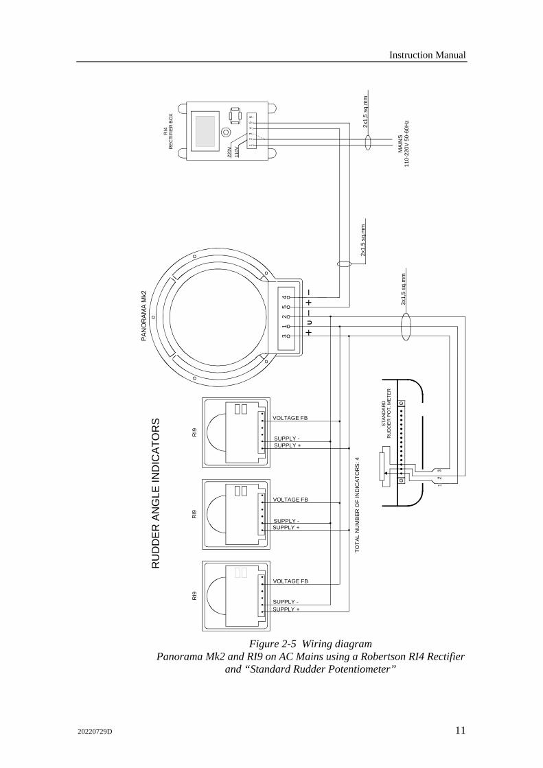
Figure 2-5 Wiring diagram
Panorama Mk2 and RI9 on AC Mains using a Robertson RI4 Rectifier and “Standard Rudder Potentiometer”

Simrad Panorama Mk2 Indicator
12 20220729D
VOLTAGE FB
SUPPLY +
3x1,
5 sq
.mm
RF1
4XU
RU
DD
ER
FE
ED
BA
CK
UN
IT
TOTA
L N
UM
BE
R O
F IN
DIC
ATO
RS
: 4
RU
DD
ER
AN
GLE
IND
ICAT
OR
S
RI9
RI9
RI9
PAN
OR
AM
A M
k2
FOR
RI4
AN
D O
THE
R U
NS
MO
OTH
ED
24V
SU
PP
LY C
ON
NE
CT
THE
E
NC
LOS
ED
CA
PA
CIT
OR
AS
SH
OW
N
NO
TE:
31
25
4
8910U
SUPPLY -
VOLTAGE FB
SUPPLY +SUPPLY -
VOLTAGE FB
SUPPLY +SUPPLY -
U
2x1,
5 sq
.mm
Sup
ply
+
(NO
T SI
MR
AD S
UPP
LY)
+
Sup
ply
-
2x1,
5 sq
.mm
110/
220V
AC
24V
DC
RE
GU
LATE
D P
OW
ER
SU
PPL
Y
Figure 2-6 Wiring diagram
Panorama Mk2 and RI9 on AC Mains with regulated power supply 110/220VAC – 24VDC 2A

Instruction Manual
20220729D 13
3 RF14XU RUDDER FEEDBACK UNIT
3.1 General The rudder feedback unit transmits a signal proportional to the rudder angle. It is mounted close to the rudder stock and is mechanically connected to the rudder by a transmission link in a 1:1 ratio.
The RF14XU Rudder Feedback Unit consists of a glass-reinforced non-flammable polyester housing with a mounting plate of seawater resistant aluminium. It contains a potentiometer, limit switches and an electronic (drive) module. The electronic module contains a voltage section and a frequency section.
The voltage section outputs a voltage to the rudder angle indicator(s) which is proportional to the rudder angle. The voltage varies ±9 volts with half the supply voltage as reference.
The frequency section generates a variable frequency signal with 3400 Hz as midposition reference. This section is only used if a Robertson autopilot is connected to RF14XU. The signal varies at a rate of 20 Hz/degree, increasing when the rudder moves to port and vice versa.
The shaft of the Feedback Unit is free to travel 360 degrees, however only ±90 degrees from midposition are used for signal control.
RF14XU is equipped with two sets of micro switches, which can be used as electrical limit switches for the steering gear.
3.2 Technical specifications Dimensions: ................ See Figure 3-1. Protection:................... IP56 Ambient temperature: . –25 - +55°C Operating voltage: ...... 19-40V (Frequency section 12-40V DC) Output RAI: ................ Midship reference:
0.5 x supply voltage Full deflection: ±9V
Output autopilot: ......... 3400Hz ±20Hz/degree No. of indicators: ........ 8 in parallel Rudder angle:.............. ±45° (Changeable to 60, 70 or 90°) Limit switches:............ Adjustable from ±5 to ±160°
Simrad Panorama Mk2 Indicator
14 20220729D
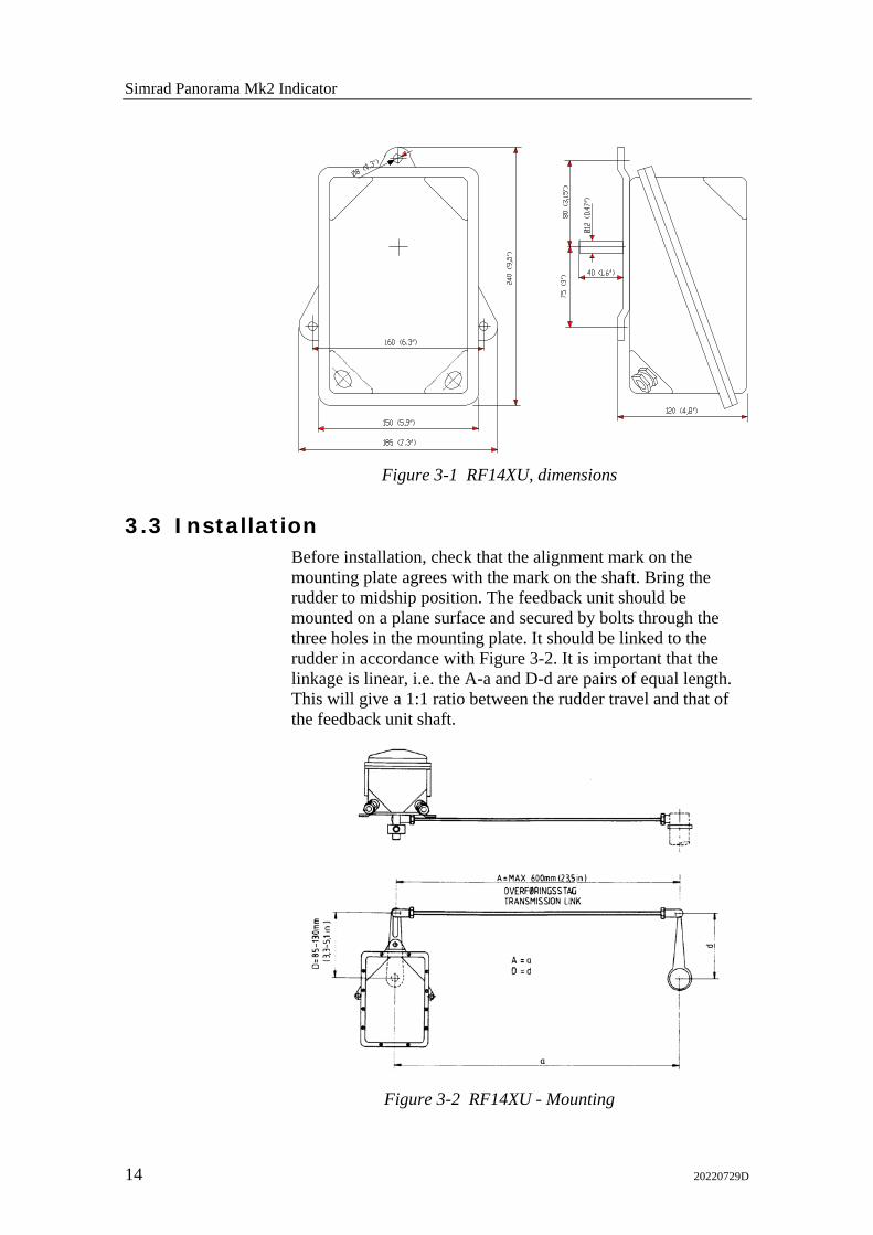
Figure 3-1 RF14XU, dimensions
3.3 Installation Before installation, check that the alignment mark on the mounting plate agrees with the mark on the shaft. Bring the rudder to midship position. The feedback unit should be mounted on a plane surface and secured by bolts through the three holes in the mounting plate. It should be linked to the rudder in accordance with Figure 3-2. It is important that the linkage is linear, i.e. the A-a and D-d are pairs of equal length. This will give a 1:1 ratio between the rudder travel and that of the feedback unit shaft.
Figure 3-2 RF14XU - Mounting

Instruction Manual
20220729D 15
3.4 Wiring Wiring to the RI9 and the Panorama Mk2 Rudder Angle Indicators is shown in Figure 2-4. Figure 2-5 and Figure 2-6 also show how a combination of RI9 and Panorama Mk2 can be connected to the RF14XU. The cables are carried through cable glands and connected to the terminal board. To avoid any mechanical damage, the cables should be run in a conduit between the rudder feedback unit and the rudder indicator(s). The cable screen must be connected to the internal ground terminal. Ref. picture below.
Figure 3-3 Screen termination
Note ! If the RF14XU and the indicators are powered from an unsmoothed 24V supply, the enclosed 470μF capacitor must be connected across the voltage supply terminals (+, –) to avoid off-set on the indicator reading.
3.5 Other rudder angles The RF14XU is normally delivered for ±45 degrees rudder angle (violet, brown and pink wires are not connected). For ±60 degrees, connect brown wire to terminal 10, for ±70 degrees, connect pink to terminal 10 and for ±90 degrees, connect the violet wire to terminal 10. White wire must remain connected. To reverse the indicator deflection, the brown wire to terminal 8 must be connected to terminal 9. All the above refer to connections between the terminal board and the internal of RF14XU, see Figure 3-4

Simrad Panorama Mk2 Indicator
16 20220729D
VIOLET
BROWN
PINK
BLAC
K
REDWH
ITE
WH
ITE
BLAC
K
RED
BLUE (GND)
YELLOW (+5V)
GREEN (WIPER)
NOTE 1
NOTE 2
9 8 10 7 6 5
RF14XU ELECTRONIC MODULE(VIEWED FROM BACK SIDE)
NOTE 1: Brown lead normally connected to . Move to to invert the rudder indicator deflection.
NOTE 2: Normally connected for +/-45° rudder angle (violet, brown and pink leads are not connected). For +/-60° connect brown lead to terminal 10, for +/-70° connect pink lead to terminal 10, for +/-90° connect violet lead to terminal 10. White lead must remain connected.
BR
OW
N
8 9
89
TOPOT.METER
Figure 3-4 RF14XU, Internal wiring
Note ! Inside the Feedback Unit cover, a piece of moisture protecting sponge is attached. The sponge produces a corrosion preventive gas, and to increase the long-life efficiency of the gas, avoid keeping the unit open over long time periods.

Instruction Manual
20220729D 17
3.6 Adjustments After having tightened all mechanical parts and connected all cables, the following adjustment must be carried out:
1. Check that the rudder is set to midship position.
2. Measure the voltage between "U" and "+", respectively "–" on the RF14XU terminal board. If the two measured voltages do not have the same numerical value, loosen the two clamping screws on the potentiometer and turn the potentiometer housing. (Figure 3-5 pos. 5) until the same numerical value is measured. The RF14XU is now set to midposition. Tighten the two clamping screws.
After installation, the cable glands should be sealed with silicon to prevent water from seeping in. Also apply silicon grease to the gasket between the bottom and top cover.

Simrad Panorama Mk2 Indicator
18 20220729D
3.7 Spare parts Part no. Pos. Description
22504005 Transmission Link 44132306 Ball joint 22500300 Shaft coupling 22500458 1 Gasket 22501605 2 Electronic XU drive module 44105120 3 Actuator 44105146 4 Limit switch 44118388 5 Potentiometer 5Kohm 44132033 6 Corrosion inhibitor sponge 22500284 7 Activator block 22500276 8 Activator disc
Figure 3-5 RF14XU - Spare Parts
Instruction Manual
20220729D 19
4 APPROVALS
4.1 Product compliance schemes Electronic navigation equipment on boats and ships within the European Common marked (EC) are regulated by two main directives: • Directive 89/336/EEC Electromagnetic Compatibility, "EMC
directive" − This directive is applicable to more or less all boats,
including leisure boats. Refer CE mark section below • Council Directive 96/98/EC of 20 December 1996 on marine
equipment, "Marine directive" or "MED" − This directive is valid for ships that come under
international conventions such as LL66, Colreg, Marpol, and Solas. Refer to the Wheelmark section below
The Marine directive requirements include the requirements of the EMC directive, and a product which comply with the Marine directive is therefore automatically also in compliance with EMC directive.
CE mark
The CE mark is placed on a product as the manufacturer’s visual identifier that the product meets the requirements of relevant European Directives. The CE mark is mandatory for a wide range of products sold within or exported to the European market, and applies to all Electric- and Electronic equipment.
When the equipment is tested according to the requirements in the Directive 89/336/EEC, the CE marking is applied to the units to symbolize Simrad’s Declaration of Conformity with the directive.
The CE declaration for any CE marked unit can be obtained from your Simrad distributor.
Wheelmark
0801/04
The Wheelmark symbol (Mark of Conformity) is an accreditation that is required for equipment placed on board ships for which safety certificates are issued by, or on behalf of, Member States of the European Union.

Simrad Panorama Mk2 Indicator
20 20220729D
Before a wheelmark can be affixed to a product, an independent organization appointed by a European national authority (a Notified body) has to undertake conformity assessment, and test reports and a MED-B certificate have to be issued. These test reports and certificates have to be kept by the manufacturer.
The manufacturer is allowed to affix the Wheelmark symbol and issue a declaration of conformity only if the manufacturer also holds a relevant QA certificate (MED-D).
The wheelmark shall be followed by:
- the identification number of the notified body (GL Luxembourg = 0801) which has performed the conformity assessment procedure and the last two digits of the year in which the mark is affixed.
Note ! When a complete system (e.g. an autopilot system) is wheelmark approved, only the main unit(s) in the system wears the wheelmark symbol. This to avoid the misunderstanding that all standard and optional units in a system retain their wheelmark approval if they are installed in a not approved system. The type examination certificate (MED-B) for the wheelmarked system lists all optional equipment that is part of the wheelmark approval. The EC Declaration of Conformity do also show which units that are part of the approval.
EU’s official database (MarED Product Database) contains information about wheelmarked equipment. This database is found on:
http://www.mared.org/
4.2 Certificates For certificates and CE declarations regarding the Panorama Mk2 indicator, refer to the following pages.
The certificates and CE declarations for any wheel marked equipment can be obtained from your Simrad distributor.

EC Certificate of Conformity
Lux
Internet Publication: GL-Approvals
Product Description Rudder Angle IndicatorIlluminated Switchboard & Navigation Instruments
Product Type TRI-2; BRW-1VTR-3 and VTR-5
Remarks None
Valid until 2009-11-23
2004-11-24
of 1
Luxembourg,
Certificate No. 24 264 - 04
EC Identification No.: 0801
Company DEIF A/S
DK-7800 Skive, DenmarkFrisenborgvej 33
Page 1
Notified Body ID No. 0801
EC Type ExaminationCertificate No.
13 802 - 99
Date of issue 23.11.2004
Valid until 22.11.2009
Item No. A.1/4.20
Conformity AssessmentProcedure
D
of a Notified Body within the meaning of Article 9 of the Marine Equipment Directive 96/98/EC of 20 December 1996.
This is to certify that the quality sytem is in conformity with the requirements of module D (Production Quality Assurance)of the Directive 96/98/EC, Annex B ensuring that the equipment identified below is conform to type as described in theEC Type Examination Certificate.
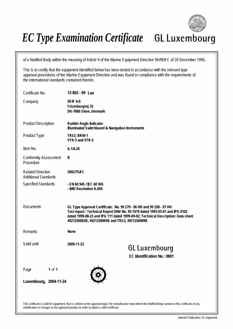
EC Type Examination Certificate
Company DEIF A/S
DK-7800 Skive, DenmarkFrisenborgvej 33
Product Description Rudder Angle IndicatorIlluminated Switchboard & Navigation Instruments
Product Type TRI-2; BRW-1VTR-3 and VTR-5
Conformity AssessmentProcedure
B
Specified Standards - EN 60 945 / IEC 60 945- IMO Resolution A.694
Documents GL Type Approval Certificate: No. 99 279 - 96 HH and 99 290 - 97 HHTest report : Technical Report DNV No. 95-1019 dated 1995-03-01 and IPG 0102 dated 1999-08-23 and IPG 111 dated 1999-09-02; Technical Description: Data sheet 4921250002B; 4921250005B and TRI-2; 4921250009B
Remarks None
Valid until 2009-11-23
LuxCertificate No. 13 802 - 99
Item No. A.1/4.20
This certificate is valid for equipment, that is conform to the approved type.The manufacturer must inform the Notified Body named on this certificate of any modification or changes to the approved product in order to obtain a valid certificate.
2004-11-24
of 1
Luxembourg,
EC Identification No.: 0801
Page 1
of a Notified Body within the meaning of Article 9 of the Marine Equipment Directive 96/98/EC of 20 December 1996.
This is to certify that the equipment identified below has been tested in accordance with the relevant typeapproval procedures of the Marine Equipment Directive and was found in compliance with the requirements ofthe international standards contained therein.
Internet Publication: GL-Approvals
Related DirectiveAdditional Standards
2002/75/EC
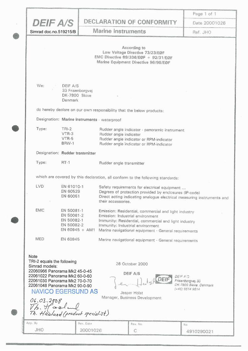
Simrad doc.no.519215/B

Panora
ma
MK2 M
anual
EN
, D
oc.
no.
20220729,
Rev
.D