simulating lightning attachment and strikes on aircraft | simulia … · 2019-06-27 ·...
TRANSCRIPT
SIMULATING LIGHTNING ATTACH-MENT AND STRIKES ON AIRCRAFTWHITEPAPER
International authorities such as the European Aviation Safety Agency (EASA) and the Federal Aviation Administration (FAA) set the basic requirements for safe aircraft operation in electromagnetic environ-ments, one example of which is lightning. Aircraft testing is used to demonstrate compliance with these regulations but unfortunately aircraft testing is expensive, time-consuming and only possible after a first prototype is built. To solve design issues at this stage of an aircraft development process could become very expensive as major design changes might be required.
To allow lightning testing to be performed earlier and more efficiently, scaled models are often used, but results of such tests have to be treated with care as the response of a scaled model to an electromagne-tic field is in general different to that of a full-size aircraft[1]. Electromagnetic (EM) simulation offers an alternative approach for analyzing the susceptibility of aircraft to lightning and other electromagnetic en-vironmental effects (E3). This article demonstrates how virtual EM aircraft testing can be performed with CST Studio Suite®, and how simulation can complement physical prototyping in the aerospace industry.
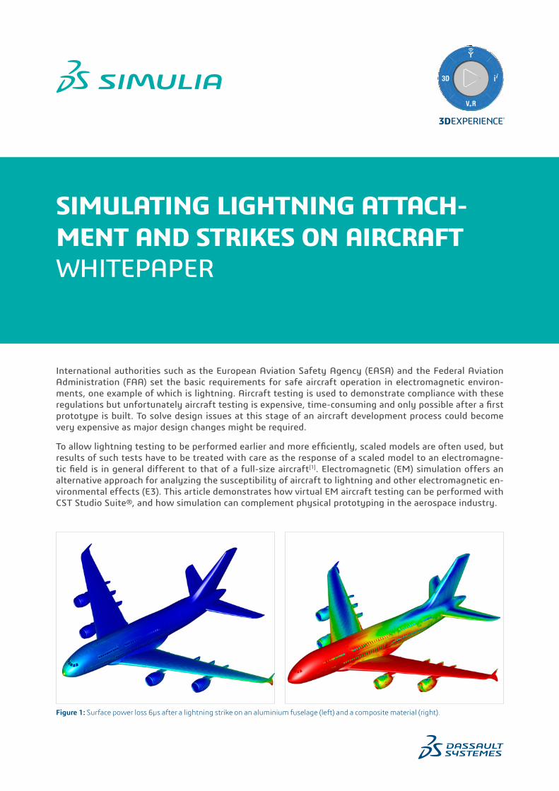
Figure 1: Surface power loss 6µs after a lightning strike on an aluminium fuselage (left) and a composite material (right).

THE PRINCIPLE OF VIRTUAL ELECTROMAGNETIC AIRCRAFT TESTING
There are three steps in the virtual EM aircraft testing pro-cess: pre-processing, EM simulation and post-processing[2]. These steps can all be performed in one common user inter-face in CST Studio Suite.
Pre-processing means preparing the model for simulation, taking the CAD data and assigning EM relevant properties such as material characteristics and the location of cable har-nesses to produce a computational model. The simulation properties are also defined, including the EM sources and boundary conditions, as well as the mesh settings and any monitors and probes needed.
In the simulation step, EM solvers are used to calculate the fields around the device. Depending on the test, these may be high-frequency or low-frequency solvers, and can be chained together. Parameter sweeps allow multiple scenari-os – for instance, different geometries or attachment points – to be analyzed in one simulation run.
The final stage, post-processing, sees the field results from the simulation converted into a format that can either be directly compared to measured data, or can undergo further analysis.
CREATING THE VIRTUAL AIRCRAFT
The first step in creating the computational model is to import the CAD data. In this case, the aircraft model was supplied in IGES format. The cable geometries can then be imported separately or modeled in the software using the CST Cable Studio solver.
The choice of material is important for assessing the suscep-tibility of the aircraft. For conventional metals such as alu-minium, an aircraft skin is still a good shield for the electric field at low frequencies but a poor one for the magnetic field[5]. However, manufacturers are increasingly turning to composites such as carbon-fiber reinforced polymer (CFRP), which has a layered structure consisting of several ply of carbon fiber woven in different directions. Compared to tra-ditional metal skins, these have more complex frequency-dependent conduction and transmission characteristics and tend to provide less shielding to interior avionics (Figure 1). Composite materials can be efficiently modeled using thin panel material, which describe the electrical behavior of the layer stackup analytically.
Field probes and current monitors are essential to calculate the progression of the lightning strike at different points on the aircraft. Current monitors can be defined around the fuselage and wings, and they integrate all current passing through their surface. Field probes inside the aircraft are useful to characterize the field coupling into the aircraft, while probes outside are useful for detecting airframe reso-nances. Time-domain volumetric field monitors can be used to visualize the lighting strike in 3D.
LIGHTNING EM PULSE SIMULATION
Once the attachment zones have been identified, the light-ning strike itself can be analyzed. Lightning EM pulse (LEMP) simulations are best performed in time domain, and the Transmission Line Matrix (TLM) solver in CST Studio Suite is especially efficient for these scenarios. It offers octree meshing, conformal meshing, compact models such as vents and seams, thin panel materials (including layered materials for composites) and uni- and bi-directional coupling with the cable solver, CST Cable Studio.
As the frequency band of a lightning signal only extends to a few MHz, the smallest mesh size is defined by the smallest structural details of an aircraft. Therefore, avoiding struc-tural details in the model not relevant from an electromag-netic point of view reduces simulation time. Otherwise, thin panel materials and compact models allow the consideration of geometrical details (e.g. multilayer laminates and seams) relevant for the EM response of an aircraft in an EM environ-ment without resolving the structural details in the mesh.
A typical lightning pulse extends up to 0.5 ms, which is com-paratively long for a transient EM simulation. However, the high-performance computing (HPC) options in CST Studio Suite, including multithreading, GPU, MPI clus-ter computing and cloud computing, allow large-scale light-ning problems to be solved in a reasonable time frame.
The lightning channel is modeled as a wire, allowing the cur-rent to enter the aircraft at one attachment zone and leave at another. In the example shown here, the lightning chan-nel sees the current injected into the left wing tip and leav-ing via the nose.
ZONING ANALYSIS
As explained in [3, 6, 8], lightning attachment to an aircraft generally starts at aircraft extremities with small curvature radii such as nose and wing tips (Figure 2). It’s in these initial attachment zones of an aircraft that an ambient electro-static field originating from thundercloud charges will be locally enhanced, enabling corona breakdowns[3].
Electrostatic field simulations can be used to characterize the initial attachment zones of an aircraft. There are two approaches that can be taken – a boundary value problem (BVP) approach, where two boundaries of the simulation domain are assigned fixed potentials, and an initial value problem (IVP) approach, where a fixed potential is assigned to the skin of the aircraft.
It’s well known that the electric field tends to be very large at aircraft extremities with a small curvature radius[7]. This field enhancement only depends on the three-dimensional shape of the aircraft extremity and not on the ambient field. Therefore it’s sufficient to solve the IVP in Figure 3 with a fixed potential assigned to the aircraft skin in open space. This means that in general, the IVP is a more efficient approach, as all attachment zones can be found in one simu-lation run, while the BVP requires three simulations to con-sider ambient E-fields in the X, Y and Z directions.
Zone 1AInitial attachment zone:High probability of direct attachment
Zone 3:Low probability of direct attachment
Zone 2A:High probability of a lightning flash beng swept
Figure 2: Lightning attachment zones according to SAE/EUROCAE, superimposed on an electrostatic field simulation. Figure 3: Electronic potential in a BVP (left) and an IVP (right).

Carrying out two simulations, one with aluminium skin and one with CFC skin, shows that the aluminium offers much more effective shielding. For this reason, a wire mesh is typically used as an additional layer of the CFC. In case of the aluminium skin, the power loss is confined to the wing edges and the nose but, in case of the CFC skin, the power loss is distributed across the left wing and the front part of the fuselage where the current is flowing from the wing tip to the nose.
The power loss distribution can be exported to the thermal solver in CST Studio Suite to allow a multiphysics simulation. This can calculate how the skin of the aircraft heats up dur-ing the lightning strike, allowing the integrity of the materi-als to be checked.
The effect of cable shielding can also be assessed through the simulation. A cable trace is laid through the aircraft, and two simulations are performed – one with the cable shield bonded to the aircraft skin, and one in which the cable shield is left open at both ends.
As can be seen from the result in Figure 4, the wire current at a probe in the left wing is higher in the unshielded wire by a factor of about 6 after 50 µs compared to the shielded case. This demonstrates the importance of a cable shield. Further coupled EM/cable simulations can be used to opti-mize the cable shielding in terms of shielding effectiveness, weight and cost.
CONCLUSIONS
Virtual electromagnetic aircraft testing complements the testing of physical prototypes in the aircraft development and certification process. Advanced EM simulation tech-nology, such as high-performance computing, thin panel materials and compact models, allows critical structures and materials to be simulated efficiently and helps engi-neers to handle the large multi-scale problem of lightning and other electromagnetic environmental effects on air-craft. In addition, 3D visualization of fields and currents offers a unique insight into the precise EM behavior of the aircraft body – one which is not available from measure-ments – and helps engineers to understand early in the design process how aircraft will react to lightning strikes.
TD Currents
shielded wire
unshielded wire
Time / µs0 10 20 30 40 50
30
25
20
15
10
5
0
Figure 4: Time domain currents through the cable, for shielded and unshielded wire.
REFERENCES
[1] D. Morgan, C.J. Hardwick, S.J. Haigh, and A.J- Meakins, “The interaction with aircraft and the challenges of lightning testing”, Journal AerospaceLab, ONERA, Issue 5, Dec. 2012.
[2] M. Kunze, Z. Reznicek, I. Munteanu, P. Tobola, and F. Wolfheimer, “Solving large multi-scale problems in CST STUDIO SUITE”, Proceedings of ICEAA, Torino, Italy, pp. 110-113, 2011.
[3] M. Kunze, “Supporting future aircraft certifications with EM simulations,” In Compliance Magazine, pp. 34-43, Jan. 2016.
[4] J. R. Elliott, P. H. Ng, S. F. Kwalko, and R. A. Perala, “From CAD Drawings to Pin Volatges, Computing Electromagentic Effects on Aircraft and Aerospace Vehicles”, Proceedings of IEEE EMC Symposium, Istanbul, Turkey, pp. 375-377, 2003.
[5] C.R. Paul, Introduction to Electromagnetic Compatibility, John Wiley & Sons, New Jersey, 2006.
[6] C. Karch, and C. Metzner, “Lightning Protection of Carbon Fibre Reinforced Plastics – An Overview”, Proceedings of the International Conference on Lightning Protection, Estoril, Portugal, 2016.
[7] H. Zscheile, F. J. Schmückle, and W. Heinrich, “Finite-Difference Formulation Accounting for Field singularities”, IEEE Trans. on Microwave Theory and Techniques, vol. 54, No. 5, May 2006.
[8] M. Kunze, “Efficient Assessment of Aircraft Initial Lightning Attachment Zones based on Electrostatic Simulations”, Proceedings of International Conference on Lightning and Static Electricity, Nagoya, Japan, 2017.
AUTHOR
Marco Kunze, SIMULIA Senior Solution Consultant.

Our 3DEXPERIENCE® platform powers our brand applications, serving 12 industries, and provides a rich portfolio of industry solution experiences.
Dassault Systèmes, the 3DEXPERIENCE® Company, provides business and people with virtual universes to imagine sustainable innovations. Its world-leading solutions transform the way products are designed, produced, and supported. Dassault Systèmes’ collaborative solutions foster social innovation, expanding possibilities for the virtual world to improve the real world. The group brings value to over 210,000 customers of all sizes in all industries in more than 140 countries. For more information, visit www.3ds.com.
Europe/Middle East/AfricaDassault Systèmes10, rue Marcel DassaultCS 4050178946 Vélizy-Villacoublay CedexFrance
AmericasDassault Systèmes175 Wyman StreetWaltham, Massachusetts02451-1223USA
Asia-PacificDassault Systèmes K.K.ThinkPark Tower2-1-1 Osaki, Shinagawa-ku,Tokyo 141-6020Japan
©20
18 D
assa
ult S
ystè
mes
. All
righ
ts re
serv
ed. 3
DEX
PER
IEN
CE®
, the
Com
pass
icon
, the
3D
S lo
go, C
ATI
A, S
OLI
DW
OR
KS, E
NO
VIA
, DEL
MIA
, SIM
ULI
A, G
EOVI
A, E
XALE
AD
, 3D
VIA
, B
IOVI
A, N
ETVI
BES
, IFW
E an
d 3D
EXCI
TE a
re c
omm
erci
al tr
adem
arks
or r
egis
tere
d tr
adem
arks
of
Das
saul
t Sys
tèm
es, a
Fre
nch
“soc
iété
eur
opée
nne”
(Ver
saill
es C
omm
erci
al R
egis
ter #
B 3
22 3
06 4
40),
or it
s su
bsid
iari
es in
the
Uni
ted
Stat
es a
nd/o
r oth
er c
ount
ries
. All
othe
r tra
dem
arks
are
ow
ned
by th
eir r
espe
ctiv
e ow
ners
. Use
of a
ny D
assa
ult S
ystè
mes
or i
ts s
ubsi
diar
ies
trad
emar
ks is
sub
ject
to th
eir e
xpre
ss w
ritt
en a
ppro
val.