simulation and analyses of a novel air-conditioning
TRANSCRIPT

Corresponding author: CAI Liang2, a, [email protected].
Simulation and Analyses of a Novel Air-conditioning Solution for Improving Energy Saving in a Data Room
Li Tong1, CAI Liang2, a and zhang xiao3
Southeast University
Abstract. In view of the feature of long airflow path, high wind resistance, and large area of refrigeration equipment in traditional data room, a new type of under-floor modular air conditioner and its corresponding new air conditioning solution for data room is proposed in this paper. The mathematical and physical model of the new solution for data room is established through a computational fluid simulation software and compared with two mainstream air conditioning solutions. Meanwhile, the impact of these three different air conditioning solutions on the temperature field, airflow field and energy consumption are analysed. The results show that the new type air conditioning solution for data room not only can be used to improve the distribution of temperature and airflow in the data room, but also can greatly reduce the energy consumption of the system.
1 Introduction
In recent years, the capacity of a single cabinet has become larger and larger, increasing toward 10-30kw. The direct impact is the increase of the energy consumption and the heat dissipation capacity required by the cabinet [1]. Traditional air conditioning solutions are becoming difficult to meet the power consumption requirements of high-density cabinet. Therefore, many energy-saving technologies and solutions for air conditioning systems in data room have emerged [2,3].
At present, these technologies and solutions can be divided into three methods: energy saving of air conditioning equipment, utilization of natural cold sources, and optimization of airflow organization [4]. For example, the installation of partitions on the top of the rack on the cold aisle side or part of the cold aisle is enclosed to improve the airflow organization of the traditional under-floor air supply data room [5,6]. The opening rate of the cabinet door, the opening rate of the internal partition of the cabinet, the number and position of the exhaust fan of the cabinet or the number of air outlets can be changed to improve the airflow and temperature distribution in the cabinet and data room [7-9]. In addition, Yajing Jiang [10] compared the line level air conditioning system and the under-floor air supply system through numerical simulation to figure out that the line level system can shorten the air supply distance and reduce the cooling loss. Liu Fang [11] point out that the diagonal arrangement of the air conditioner can increase the air supply range, reduce the heat convection interference between the cabinets, and effectively reduce the local hot spots in data room using inter-row air conditioners.
However, the traditional under-floor air supply system still has some disadvantages such as long airflow path, high wind resistance, easy to be affected by obstacles [12]. The line level air conditioning system also has some natural defects, such as a low space utilization efficiency caused by the air conditioner occupying the cabinet position and high noise [13].
Therefore, a new type of under-floor modular air conditioner and its corresponding new air conditioning solution for data room are proposed in this paper. Using CFD simulation methods, compared with the existing mainstream solutions, the advantages of the new solution for improving the temperature and airflow field and reducing energy consumption are analysed.
2 UMAC system introduction
2.1 Air conditioning structural design
The 3D model of the new designed under-floor modular air conditioner (UMAC) used in data center is shown in the figure 1.
Because the standard of the raised floor size in data center is 600mm×600mm, the width of the unit is set to 600mm, and the length is set to the length of 4 floors, which is 2400mm. The height of the unit can be adjusted within this range of 300-900mm according to the cooling power requirements. The top of the UMAC unit are set as air inlets and outlets, the size of the air inlets and outlets should follow the size of the raised floor, that is, 600mm×600mm. The air outlet on the left is installed in the cold aisle and the air inlet on the right is installed in the hot aisle. The supply and return air only go through a
E3S Web of Conferences 233, 010 (2021)IAECST 2020
81 https://doi.org/10.1051/e3sconf/202123301081
© The Authors, published by EDP Sciences. This is an open access article distributed under the terms of the Creative Commons Attribution License 4.0 (http://creativecommons.org/licenses/by/4.0/).

very short path and not interfered by any obstacles, which can greatly improve the air supply efficiency.
Figure 1. The 3D model of the UMAC unit.
The internal structure of the unit is shown in Figure 2: 1 fan; 2 electric control box; 3 evaporator coil; 4 air release valve; 5 water inlet pipe; 6 water outlet pipe; 7 water flow regulating valve; 8 chilled water inlet; 9 chilled water outlet; 10 for external equipment
Figure 2. The internal structure of the UMAC unit.
2.2 Numerical model of UMAC unit is established
Referring to the design drawings of the unit, ignoring some structural details, a detailed model of the 10kw UMAC unit was established through CFD software. The relevant setting parameters are as follows:
(1) Heat Exchanger A copper tube aluminum fin heat exchanger is
installed in the air conditioner, which has the characteristics of low wind resistance, high cooling capacity, and high efficiency. The specific parameters are listed in Table 1.
Table 1. Heat exchanger parameters.
Type Value Unit
Coil length 1050 mm
Coil width 480 mm
Number of loops 6 /
Heat exchange tube diameter
8.62 mm
Heat exchange tube wall thickness
0.68 mm
Fin pitch 2.2 mm
Fin thickness 0.115 mm
Rated cooling capacity 10.5 kw
Performance 0.8 /
(2) Return air outlet and fan The return air outlet is on the top of the unit,
rectangular perforated type, simple to manufacture and easy to process. The fan can be selected according to the cooling capacity of the air conditioner.
The specific parameters of return air outlet and fan are listed in Table 2 and Table 3.
Table 2. Return air outlet parameters.
Type Value Unit length 520 mm
width 520 mm Hole Size 30×30 mm
Hole proportion 68 %
Table 3. Fun parameters.
Type Value Unit
Inlet diameter 500 mm
Wheel diameter 200 mm
Rated speed 1000 rpm
The new designed UMAC unit has many advantages and makes up for some of the shortcomings of traditional air conditioners. The 3D effect after installation is shown in Figure 3.
Figure 3. 3D effect after installation of the UMAC unit.
As is shown in the figure3, the UMAC unit is installed under the floor directly under the server cabinet. Fan on one side sends cold air upwards. After cooling the server, the formed hot air reaches the other side and returns to the unit, forming a complete air circulation.
The advantages of this solution are mainly reflected in these following points. By installing the air conditioner in the raised floor space without occupying any ground area, this solution can maximize the use of the space of the data room. Besides, it also has the shortest airflow path, which can greatly reduce the loss of cold air and improve unit efficiency. Moreover, the raised floor separates the air conditioning equipment from the IT equipment, so that even if water leakage and other faults occur, the servers in the cabinets can operate safely.
Therefore, the design of this air conditioning solution is feasible. Each cabinet combined with an air conditioner could be viewed as a small system, forming a stable and uniform airflow field, which can also meet the requirements for modular construction of data centers and lower energy consumption.
E3S Web of Conferences 233, 010 (2021)IAECST 2020
81 https://doi.org/10.1051/e3sconf/202123301081
2
3 Simulation of data rooms using different air conditioning solutions
3.1 Establishment of model
In order to compare the impact of different air conditioning solutions on energy consumption, this paper uses the same actual data room model. Only the indoor air conditioning solution is changed, that is, the room level air conditioning solution, the line level air conditioning solution and the new solution using UMAC units. When analyzing, only the energy consumption caused by different air conditioning solutions are considered.
The data room modeling conditions are as follows: (1) The size is based on the actual area of the data
room which is 280.8 m2 (18 m×15.6 m), and the height of the data room is 3.3 m;
(2) The size of cabinet is 600 mm (width) × 1200 mm (depth) × 2050 mm (height), with servers in the cabinet, and blind plates are added;
(3) The power consumption of a single cabinet is 10kw;
(4) The width of the cold aisles is 1.2 m; (5) The ambient temperature outside the data room is
the default value of 20°C.
3.2 Energy saving analysis of air conditioning solutions
3.2.1 Analysis of data room using room level air conditioning solution
Figure 4. The layout of the data room using room level air
conditioning solution.
According to the data room construction plan, the ambient air conditioners are arranged on both sides of the data room through the under-floor air supply. A total of 120 cabinets can be arranged, with a single cabinet is 10kw. The layout of the data room is shown in Figure 4.
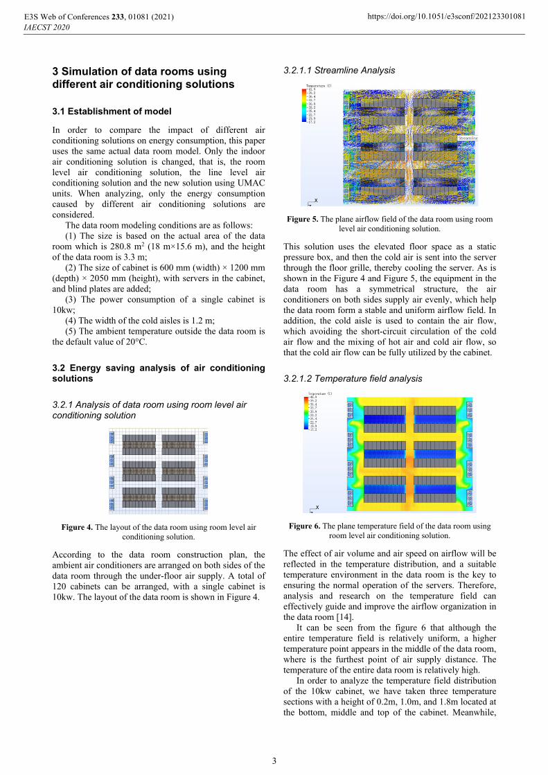
3.2.1.1 Streamline Analysis
Figure 5. The plane airflow field of the data room using room
level air conditioning solution.
This solution uses the elevated floor space as a static pressure box, and then the cold air is sent into the server through the floor grille, thereby cooling the server. As is shown in the Figure 4 and Figure 5, the equipment in the data room has a symmetrical structure, the air conditioners on both sides supply air evenly, which help the data room form a stable and uniform airflow field. In addition, the cold aisle is used to contain the air flow, which avoiding the short-circuit circulation of the cold air flow and the mixing of hot air and cold air flow, so that the cold air flow can be fully utilized by the cabinet.
3.2.1.2 Temperature field analysis
Figure 6. The plane temperature field of the data room using room level air conditioning solution.
The effect of air volume and air speed on airflow will be reflected in the temperature distribution, and a suitable temperature environment in the data room is the key to ensuring the normal operation of the servers. Therefore, analysis and research on the temperature field can effectively guide and improve the airflow organization in the data room [14].
It can be seen from the figure 6 that although the entire temperature field is relatively uniform, a higher temperature point appears in the middle of the data room, where is the furthest point of air supply distance. The temperature of the entire data room is relatively high.
In order to analyze the temperature field distribution of the 10kw cabinet, we have taken three temperature sections with a height of 0.2m, 1.0m, and 1.8m located at the bottom, middle and top of the cabinet. Meanwhile,
E3S Web of Conferences 233, 010 (2021)IAECST 2020
81 https://doi.org/10.1051/e3sconf/202123301081
3

we took the average temperature of the cold aisle, hot aisle, and the middle of data room at each height. Table 4 shows the average temperature.
Table 4. Average temperature of three place in three sections.
Average temperature (℃)
Bottom section (0.2 m)
Middle section (1.0 m)
Top section (1.8 m)
Cold aisle 17.3 18.6 19.9 Hot aisle 30.7 31.3 32.5
Middle of data room
33.8 35.1 37.8
The data in this table will be compared and analyzed later with the other two air conditioning solutions.
3.2.2 Analysis of data room using line level air conditioning solution
The construction of the line-level data room adopts the method that the air supply between rows and air conditioners are arranged in the middle of the cabinets. A total of 108 cabinets and 36 air conditioners can be arranged, with one spare for every 6 air conditioners. The power of a single cabinet is 10kw, and the layout of the data room is shown in Figure 7.
Figure 7. The layout of the data room using line level air conditioning solution.
3.2.2.1 Streamline Analysis
Figure 8. The plane airflow field of the data room using line level air conditioning solution.
The data center uses inter-row air conditioning units, with small fans inside the cabinets. One side of the cabinets enter the cold air. After the cold air exchanges heat with the heating server, the heat is taken away, and
hot air is discharged to the other side [15]. The streamline is shown in Figure 8. From the streamline diagram, the air conditioning system of the data center basically meets the design requirements, and the airflow organization is good. But the air speed at the outlet of the air conditioner is relatively high, the airflow is chaotic, and the hot airflow is mixed with the cold airflow.
3.2.2.2 Temperature field analysis
Figure 9. The plane temperature field of the data room using line level air conditioning solution.
Due to the design, the air conditioner supplies air between the rows of the cabinets. The temperature difference between the hot and cold aisles is relatively obvious, and the temperature of the hot aisle is generally higher, which helps to improve the energy efficiency of the air conditioner [16]. But the phenomenon of chaotic air flow, and the mixing of hot air and cold air may cause unstable temperature field.
We also intercepted the same temperature sections as the data center using room level air conditioning solution above. Data are listed in Table 5.
Table 5. Average temperature of three place in three sections.
Average temperature (℃)
Bottom section (0.2 m)
Middle section (1.0 m)
Top section (1.8 m)
Cold aisle 14.1 19.2 24.6 Hot aisle 31.7 32.3 33.5
Middle of data room
23.1 25.5 27.8
The data in this table will be compared and analyzed later with the other two air conditioning solutions.
E3S Web of Conferences 233, 010 (2021)IAECST 2020
81 https://doi.org/10.1051/e3sconf/202123301081
4

3.2.3 Analysis of data room using under-floor modular air conditioners
Figure 10. The layout of the data room using UMAC units.
According to the construction plan, the new data room uses under-floor modular air conditioning unit, the bottom air supply method is adopted. Meanwhile, the air conditioners are arranged at the bottom of the floor, directly below each cabinet. A total of 144 cabinets and 144 air conditioners can be arranged. Each unit has redundant cooling capacity. The power of a single cabinet is 10kw, and the layout of the data room is shown in Figure 10.
3.2.3.1 Streamline Analysis
Figure 11. The airflow line of the data room using UMAC units (from the side).
Figure 11 and Figure 12 help us clearly view the airflow line of the data room using under-floor modular air conditioning units from the side and above. The new designed data center air conditioning system has a clear structure and forms a uniform and stable airflow field around the cabinet. There is no turbulence in the airflow, avoiding the phenomenon of chaotic airflow and the mixing of hot air and cold air, which helps greatly improve the operating efficiency of air conditioning unit and efficiency of airflow organization.
Figure 12. The plane airflow field of the data room using UMAC units.
3.2.3.2 Temperature field analysis
Figure 13. The plane temperature field of the data room using UMAC units.
As is shown in the Figure 13, the temperature field is very uniform caused by the stable airflow organization. In the closed cold aisle and hot aisle, the temperature of the airflow is basically stable, which is especially suitable for data centers with high capacity cabinets or high local heat density. In addition, because of the shortest air supply path, the energy loss during air delivery is greatly reduced, the energy consumption of air conditioning unit is also greatly reduced.
Temperature data about the data room using UMAC units are listed in the Table 6.
Table 6. Average temperature of three place in three sections.
Average temperature (℃)
Bottom section (0.2 m)
Middle section (1.0 m)
Top section (1.8 m)
Cold aisle 19.2 20.4 21.5
Hot aisle 28.1 29.3 29.7
Middle of data room
23.1 24.2 24.8
The data in this table will be compared and analyzed later with the other two air conditioning solutions.
4 Comparative analysis of different air conditioning solutions on energy consumption
4.1 Analysis of the temperature field of different air conditioning solutions
Figure 14. Temperature comparison of different heights in cold aisle
E3S Web of Conferences 233, 010 (2021)IAECST 2020
81 https://doi.org/10.1051/e3sconf/202123301081
5

Figure 14 is the temperature comparison of different heights in the cold aisle. The temperature of the room level solution tends to be uniform because sufficient and stable cold airflow is provided for the cold aisle. The line level solution is prone to mix hot air with cold air in the cold aisle, so the temperature of the cold aisle is quite different. As for the UMAC solution, due to the design of closed cold and hot channel with uniform air flow, the temperature in cold aisle has little difference.
Figure 15. Temperature comparison of different heights in hot aisle.
Figure 15 is the temperature comparison curve of the different heights in the hot aisle. For the room level solution and the line level solution, the temperature in hot aisle are relatively high and tend to be consistent. However, due to the mixing of cold and hot airflow in hot aisle in the data room using room level solution, it has a lower temperature in hot aisle. As for the UMAC solution, a separate channel that the other two solutions don’t have for hot airflow exhausted from the cabinet helps the hot aisle keep a low temperature.
Figure 16. Temperature comparison of different heights in the middle of data room.
Figure 16 is the temperature comparison curve at different heights in the middle of the data room. The main reason that affects the temperature of the middle of the data room is the way of air supply. The room level solution sends cold airflow from both sides of the room to the middle of the room. When the cold airflow reaches the middle of the room, the cooling capacity has been greatly depleted, that’s why a higher temperature appears in the middle of the room. Since the other two solutions directly send cold air into the cabinet, the temperature is relatively lower. Obviously, the nearby air supply is more conducive to reducing the temperature in the middle of the data room.
In summary, the UMAC air conditioning solution has a lower temperature anywhere in the data room, without
a particularly obvious high temperature point. Meanwhile, it achieves the most uniform airflow field and temperature field, making the servers operate safely and reliably.
4.2 Calculation for energy-saving effects of data room using three air conditioners
We have calculated the energy-saving effects of the above three air-conditioning solutions, and the conditions and calculation results are listed in Table 7.
Table 7. Calculation conditions and results.
Solution of ACs Room level
Line level
UM AC
Cabinet capacity(kw) 10 10 10
Number of cabinets 120 108 144 Total cabinet capacity(kw)
1200 1080 1440
Number of ACs 8 30/6 144 Cooling capacity of a
single AC (kw) 162 42.2 10.2
Power consumption of a single AC (kw)
10.7 1.7 0.28
EER 15.1 24.8 36.4 Total power
consumption of ACs(kw)
85.6 51 40.32
Operational benefits(kw/kw)
14 21.2 35.7
As shown in Table 7, in the three cases of this paper, having the same size of the data room, the data room using UMAC units can accommodate 24 and 36 more 10kw cabinets than the other two solutions, that is, handle more heat load. Meanwhile, although the number of air conditioners in the data room using UMAC units is higher than the other two solutions, the total power consumption is lower than the other two solutions by 20.9% and 52.9%. The above two points make the data room using UMAC units have good economic benefits.
Figure 17. EER and operational benefits of three solutions.
In addition, the cabinet capacity solved by each unit of operating power consumption of air conditioners is used to express the operating benefits of the air conditioning solution. As is shown in the Figure 17 with the EER (energy efficiency ratio) of the three air conditioning solutions, taking the calculation error into account, the two curves are basically similar. Obviously, the operating efficiency of the data room using UMAC
E3S Web of Conferences 233, 010 (2021)IAECST 2020
81 https://doi.org/10.1051/e3sconf/202123301081
6

units is higher than that of the data room using room level and row level solutions.
5 Conclusion
This paper proposes an under-floor modular air conditioner (UMAC). The numerical model of the UMAC unit and its corresponding data center are established through CFD software. The airflow field, temperature field and energy consumption results of it are also compared with the mainstream room-level and line-level data center air conditioning solutions. Conclusions are drawn as follows:
(1) Data centers using UMAC units can make better use of the space of data room and install more server cabinets by installing the air conditioners under the raised floor. In the cases of this paper, this solution can place 20% and 33.3% more cabinets than room-level and line-level air-conditioning solutions.
(2) The new data center air-conditioning solution also has better energy-saving effects. In the cases of this paper, the UMAC units cool 20% and 33% more cabinets than the room-level and line-level solutions under the premise of using 52.9% and 20.9% less energy consumption than the above two solutions.
(3) Data center using UMAC units has a more uniform and stable airflow field and temperature field than the other two solutions. Meanwhile, there is no obvious high temperature point in the data room using UMAC units, which makes the servers in the cabinets operate safer and more reliable.
Acknowledgement
This work was financed by the National Key Research and Development Program of China (Grant No. 2018YFC0705306), the Natural Science Foundation of China (Grant No. 6503000103).
References
1. Jie Chen. Application and simulation analysis of the cold aisle sealing technology in data room. HVAC. J.,45(6):37-40(2015).
2. Guangming Zhang. The sustainable status of data center and energy-saving technology. Building Science. J.26(10): 63-67(2011)
3. Xiaohua Yang. Analysis and Research on Energy Saving Technology of Data Center. Electrical Application. J. 21(3): 34-38(2011)
4. Xiuming Cheng, Jiugeng Zhang. Data center computer room air conditioning system design and airflow optimization analysis. Fluid Machinery. J.42(11): 79-86(2014)
5. Liu Cheng, Letian Chen, Ying Wang. Study of rational air distribution on the air conditioning system for telec om rooms. Building Energy& Environment. J.29(5): 80-84 (2010)
6. Caifeng Gao, Yu Zhen, Jianlin Wu. Investigation of airflow pattern of a typical data center by CFD simulation. Energy Procedia.J.78 (2): 2687-2693 (2015)
7. Gilder J W, Schmidt R R. Airflow uniformity through perforated tiles in a raised-floor data center[R]. ASME Paper No.IPACK(3):73-75(2005)
8. Patankar S V. Airflow and cooling in a data center. Journal of Heat Transfer.J.132(7):1-17 (2010)
9. Nada S A, Said M A, Rady M A. Numerical investigation and parametric study for thermal and energy management enhancements in data center buildings. Applied Thermal Engineering.J.98 :110- 128(2016)
10. Yajing Jiang, Chen Liu. Numerical simulation of inter-row air-conditioning in high-density data center. Building Energy-saving Ventilation and Air conditioning. J.31(6):92-95(2012)
11. Fang Liu, Zhigang Wang. Simulation Research on Air Distribution of Indoor Air Conditioning in a Data Center. Building Energy Efficiency.J.10(44): 11-17(2016)
12. Schmidt R R, Cruz E. Raised floor computer data center: effect on rack in Iet temperatures of chilled air exiting form both the hot and cold aisles[C]// Proceedings of ITherm 2002 Eighth InterSociety Conference on Thermal and Themomechanical Phenomena in Electronic systems. SanDiego: 580-594(2002)
13. Xiaodong Qian, Zheng Li. Research on Energy Saving of Air Conditioning System in Data Center.HVAC.J.42(3):91-96(2012)
14. Jennifer D, Mitchell, Jackson. A Close Look at Data Centers. ASHRAE Journal.J.7:2-3(2001)
15. Jie Dun, Yun Qing, Xing Guan. Simulation and optimization of airflow organization in data center computer room based on Fluentairpak. Building energy efficiency. J. 3(43):27-33. (2015)
16. Haiyu Sun, Dongqi Liu. The deployment practice of the computer room based on the cold box of the inter-row air conditioner. Telecom Technology. J.2016(4): 85-88.
E3S Web of Conferences 233, 010 (2021)IAECST 2020
81 https://doi.org/10.1051/e3sconf/202123301081
7