simulation and digital twin based design of a … · for electric motors brake disk support plates....
TRANSCRIPT

Abstract—This paper is aimed to optimize a machining cycle
for electric motors brake disk support plates. Today it is
possible to adopt modeling and simulation techniques that
thank to the increasing power of technologies and the Industry
4.0 platform allow understanding the impacts of changes in the
production and therefore verifying its effectiveness and limits.
In this context, the Digital twin (DT) implements concepts that
try to solve the problem of handling large amounts of data that
is accessed concurrently and has numerous internal semantic
dependencies. The purpose of this paper is to provide an
application of DT through the adoption of simulation
techniques. The sample takes inspiration from a real plant,
which produces anchoring plates for electric motor brake discs
The weakness point of the cycle is represented by problems
arising from its discontinuity. To simulate and study solutions,
AnyLogic software was used to create virtual simulation
models.
Index Terms—Production design, Digital twin, Industry 4.0,
Simulation, Anylogic
I. INTRODUCTION
PTIMIZING an existing production process or
designing a new one involves huge investments, as
well as the adoption of innovative technologies that require
reengineering activities, training and updating courses for
workers.
The results evaluation of these operations in the real
world can be once again expensive and in some cases even
unbearable. However today, it is possible to recur to
modeling and simulation techniques that thank to the
increasing power of these technologies and the Industry 4.0
platform allow understanding the impacts of changes in the
production and therefore verifying its effectiveness and
Manuscript received December 08, 2017; revised January, 20, 2018.
L. D. is with the University of Genoa, Department of Mechanical
Engineering, Via Opera Pia 15, 16132 Genoa, Italy (e-mail:
M. D. is with the University of Genoa, Department of Mechanical
Engineering, Via Opera Pia 15, 16132 Genoa, Italy (e-mail:
P. G. is with the University of Genoa, Department of Mechanical
Engineering, Via Opera Pia 15, 16132 Genoa, Italy (e-mail
M. M. is with the University of Genoa, Department of Mechanical
Engineering, Via Opera Pia 15, 16132 Genoa, Italy.
R. R. is with the University of Genoa, Department of Mechanical
Engineering, Via Opera Pia 15, 16132 Genoa, Italy (Phone number: + 39
339874234; e-mail: [email protected]).
F. T. is with the University of Genoa, Department of Mechanical
Engineering, Via Opera Pia 15, 16132 Genoa, Italy (e-mail:
limits [1]. Thus digital models can replace physical
components accurately.
In this sense the Digital twin (DT) implements concepts
that try to solve the problem of handling large amounts of
data that is accessed concurrently and has numerous internal
semantic dependencies. The common understanding of the
DT is that is a virtual representation that provides
engineering, simulation, or runtime products with a virtual
reflection of the real world throughout multiple phases of
the product or plant lifecycle [2].
It stores a broad range of different types of data including
operational parameters, behavioral, structural and process
models that allow users and machines to find and access the
right data at the right time in a secure way.
The DT is not a design, engineering or simulation tool
itself. It does not plan, control, supervise, or simulate
production processes and it does not execute business logic.
It does not analyze data or optimize parameters. But it does
provide all those tools with the data they need.
The aim of the DT is to provide designers and operators
of industrial machines, production and process plants, or
cyber-physical systems in general with a unified and
structured way to store, retrieve and manage data that are
relevant the system’s automation function [3]. It should
support developers and operators in the design and runtime
phases of the system’s lifecycle. The technical domain of
the DT is the area of industrial manufacturing and process
automation in the narrow sense with a focus on the lifecycle
phase’s design, planning and execution.
The purpose of this paper is to provide an application of
DT implemented through the adoption of simulation
techniques [4].
The paper is organized as follows. Section 2 presents the
literature review while Section 3 and 4 shows the case
description and the simulation model implementation.
Section 5 presents the results of the study and finally,
Section 6 provides conclusions and future developments.
II. LITERATURE REVIEW
A qualitative literature review has been performed in
order to provide i) the theoretical framework for this
research and ii) the definition of key terms and topics
related to our study. Papers were selected from Scopus,
authors chose this database for its ample coverage of articles
in this field. It offers search combinations using “and” and
the possibility to search for keywords. The qualitative
literature review process was composed of two parts: firstly,
an explorative and unstructured one that had a number of
Simulation and Digital Twin Based Design of a
Production Line: A Case Study
Lorenzo Damiani, Melissa Demartini, Piero Giribone, Margherita Maggiani, Roberto Revetria, Flavio
Tonelli, Member, IAENG
O
Proceedings of the International MultiConference of Engineers and Computer Scientists 2018 Vol II IMECS 2018, March 14-16, 2018, Hong Kong
ISBN: 978-988-14048-8-6 ISSN: 2078-0958 (Print); ISSN: 2078-0966 (Online)
IMECS 2018

different origins; and secondly, a more structured one
involving searching databases using search strings and
dashboards [5].
Authors’ strategy was to identify articles that included
“digital twin” and “production” as keywords in all fields.
Additionally, Authors took into account various synonyms
of each of these terms such as “industry 4.0” and “smart
factory”. Our search identified 44 empirical academic
papers that were published between 2015 and 2017. Their
titles, abstracts and texts were reviewed in detail for
relevance to the study.
The distribution of publications over the years (Figure 1)
shows a growing trend of articles and it reveals a significant
increase in 2017. This could be due to the implementation
of “Industry 4.0” techniques.
In terms of geographical distribution, the publications
reviewed where from many different countries around the
world, based on the main author's university affiliation. A
few countries stand out: Germany and The USA. Hence, it
might be argued that digitalization and DT are primarily
rooted in these countries.
Fig. 1. Distribution of publications over the year
Fig. 2. Distribution of publications over the country
Another important finding in the literature review is that a
high percentage of publications are conference papers
(55%), 41% are articles (table 1) while only 4% are book
chapters.
TABLE I
DISTRIBUTION OF PUBLICATIONS OVER THE TYPE OF CONTRIBUTION
Document type Number of publications
Conference paper 24
Article 18
Book chapter 2
Based on the findings of this review, it is possible to
establish an overview of the predominant DT
characteristics.
In the last few years, Industry 4.0 has been considered as
one of the most prevalent topic in production engineering
[6], nevertheless its methods and techniques are still
inadequately represented within manufacturing operations.
In this context the DT, as a key enabler of the Industry
4.0, follows the same trend, needing more studies and
definitions.
Demartini et al., define the DT as well as Cyber Physical
Production System (CPPS), prerequisites for the
digitalization of the Manufacturing Execution System
(MES), which enable a decentralized and self-organized
production system controlled in real time [7].
Uhlemann et al., have strengthen the link between CPPS
and DT; they claim that DT is an enabler technology for
CPPS. It acquires data, which is necessary for the CPPS
functioning. DT allows a coupling of the production system
with its digital environment as a base for an optimization
with a minimized delay between the time of data acquisition
and the creation of the Digital Twin [8].
Furthermore, Rosen et al., presents DT as an essential
condition to implement intelligent and efficient production
systems, which allow optimizing product design and
production execution for achieving higher performances.
DT is a “repository” which stores information created in
each stage of the product lifecycle and make it seamlessly
available [9].
Weyer et al. describe the DT as a “promising approach”
that is able to overcame drawbacks and reduce efforts in
reverse engineering. Once again, it is defined as a database
that contains all information in a structured way [10].
With this in mind, the scope of this paper is to develop an
application of DT using simulation techniques with the
scope of optimize a production line and control over the
product.
III. CASE DESCRIPTION
The manufacturing system proposed in this paper takes
inspiration from a real plant, which produces anchoring
plates for electric motor brake discs. Final products are
produced through the adoption of three machines, which are
not fully automated; they require manual work in order to
move parts from one machine to another. This production
cycle can be defined as an intermittent one, there is no direct
communication between machines, and therefore there is a
continuous need of operators’ support.
The first two machines, which provide milling and
grinding works, do not require continuous communication
because, are not sequential. This means that two different
products can be processed at the same time.
On the contrary, the second and the third machine, which
are called Grinding and Burton need to be linked, in fact
they have to process all products. Therefore, products can
be worked by machine 1, but works provided by the second
and third machines are mandatory for all products. What’s
more, required manual works have to be considered
between machine 2 and 3 and they involve the following
issues:
Operators have to control two machines at the
same time. This becomes particularly relevant
for those products that need manual loads in
grinding and the constant presence of the
operator near the machine in order to solve
Proceedings of the International MultiConference of Engineers and Computer Scientists 2018 Vol II IMECS 2018, March 14-16, 2018, Hong Kong
ISBN: 978-988-14048-8-6 ISSN: 2078-0958 (Print); ISSN: 2078-0966 (Online)
IMECS 2018
bottlenecks;
The possibility that machines are inactive until an
operator moves parts between them;
Operators provide works that can be carried out
automatically by machines themselves;
To improve this situation, an automatic transport system
has been introduced in order to connect machines without
the intervention of an operator.
The following factors need to be assessed and managed in
order to perform an internal automatic transport system:
State of the material to be moved:
o Solid: it can be bulk, in loading units or
packages;
o Liquid;
o Gaseous;
Operation:
o Continuous;
o Discontinuous;
Power drive:
o Manual transport;
o By means of manual trolleys;
o Slides;
o Motorized;
Type of movement:
o Vertical lifting means;
o Horizontal transport means;
o Lifting and transporting means;
o Vehicles equipped with vibratory motion;
o Means equipped with rotating movement;
Control types:
o On-board maneuver;
o Ground control;
o Without maneuver;
o Automatic.
In the case considered here, products are in solid state
(bulk) moved by horizontal continuous movement through
automatic type control and energy availability for
motorization. Therefore conveyor belts have been
introduced.
After the choosing of internal transport to be
implemented, the study of the interaction between the
system design machinery has been deepened.
The parameters considered for the design are:
Processing times;
Products’ size;
Machinery location.
These parameters allow us to define:
The conveyor belt speed;
Width;
Length and inclination.
With respect to the conveyor belt speed, in order to avoid
mutual interference between the pieces discharged by the
machine grinder, it has to vary from a minimum of 1,060
mm/min to a maximum of 1,850 mm/min.
Regarding the width of the ribbon, considering the
maximum diameter of the pieces to be transported by 188
mm, it is believed that it should not be less than 200 mm.
Finally, the plant layout should assume an L shape
considering machinery sizes and the available space. It has
been suggested to use: 4 meters for the sloping tape, 1.2
meters linearly and finally 80 cm for the load.
IV. SIMULATION MODEL
The simulation model has been implemented through
Anylogic tool and can be divided into three steps:
Representing the plant layout (using the Space
Markup functions);
Functions definition;
Real loop and parameters definition.
Firstly, to represent the plant layout, the map area of the
plant has been created towards the path command and
rectangular node in the Space Markup library of Anylogic.
Then the 3D Object library allows us to depict products,
operators, machines and the production and packaging
workings.
The Process Modeling Library allows us to model the
real-world system in terms of:
Agents (customers, pieces, products, etc);
Processes (sequences of operations);
Resources.
The production cycle is simulated in the form of flow
charts, which can be hierarchical, scalable and extensible.
The main functions used are:
Resource-Pool: defines a set of resource units that can
be retrieved and released by agents using some flow
blocks. Resources can be static, dynamic, or portable.
In this case, we define the workers as such;
Source: represents the starting point of a process model;
Queue: a queue, buffer, of agents waiting to be
accepted by subsequent objects in the process flow or in
a generic file for agents. The buffering rule can be
FIFO (first in first out), LIFO (last in first out), or
priority-based;
Delay: delays and is often needed in situations that
require some time for decision making or simulating a
work process. It is used to represent the machine cycle
time;
Seize: recalls a number of resource units defined in the
Resource Pool and sends the resources recalled to a
specific zone. In this case calls the operator in the pick-
up area of the material and in the packaging area;
Release: releases resource units previously recalled
with Seize. Resources can return to the starting position
or stay in the area where they were released;
Move To: moves the agent to a new location;
Conveyor: simulates a conveyor belt, moves agents
along a path at a certain speed while maintaining a
minimum gap between them. It was used for automatic
loading of the first machine and discharges of both;
Batch: converts a number of agents into one agent.
Used to drain the grinding to create baskets that will be
transported to the third machine;
Un-batch: extract all agents in the Batch Inbound
Agent. Employed to simulate the drainage of baskets in
the third machine.
Proceedings of the International MultiConference of Engineers and Computer Scientists 2018 Vol II IMECS 2018, March 14-16, 2018, Hong Kong
ISBN: 978-988-14048-8-6 ISSN: 2078-0958 (Print); ISSN: 2078-0966 (Online)
IMECS 2018
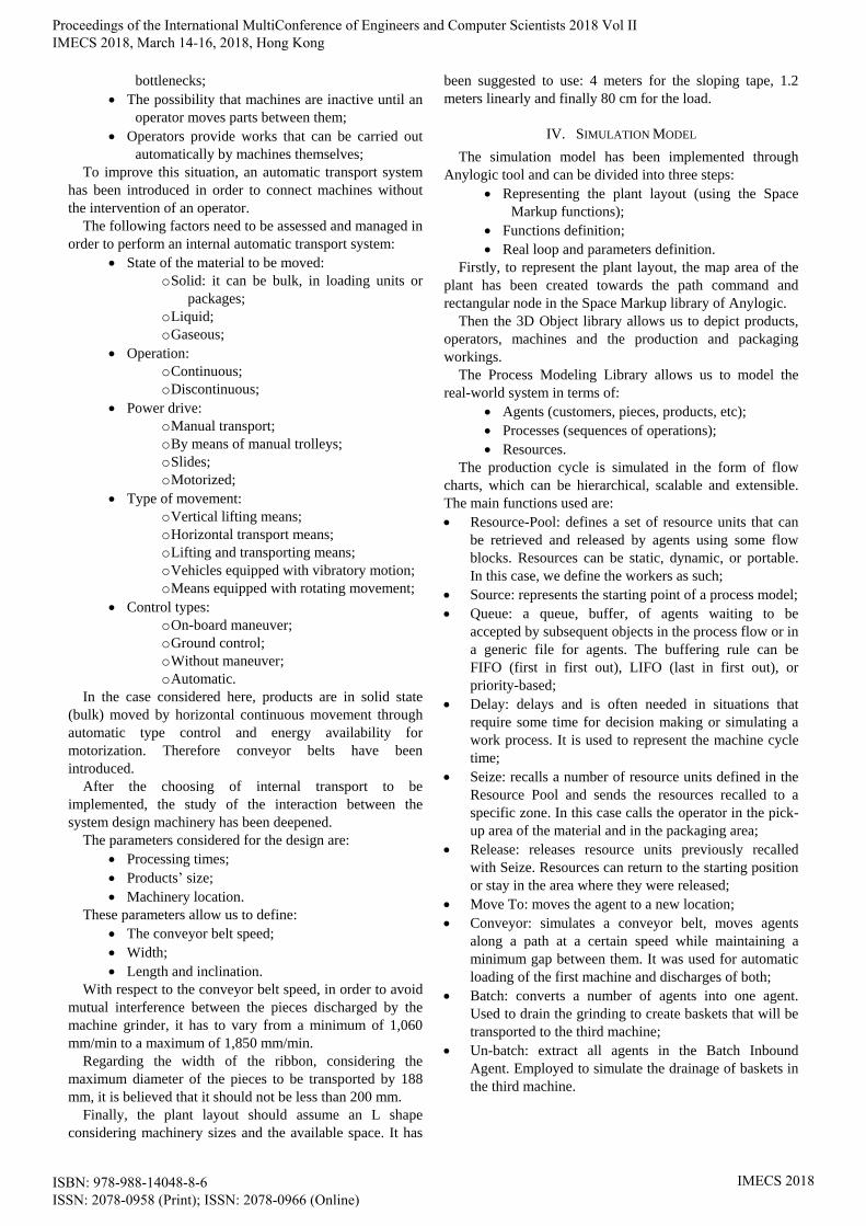
Finally, to display the 3D representation (Fig.3), the
camera function has been introduced from the Presentation
Library.
Fig. 3. 3D real workshop
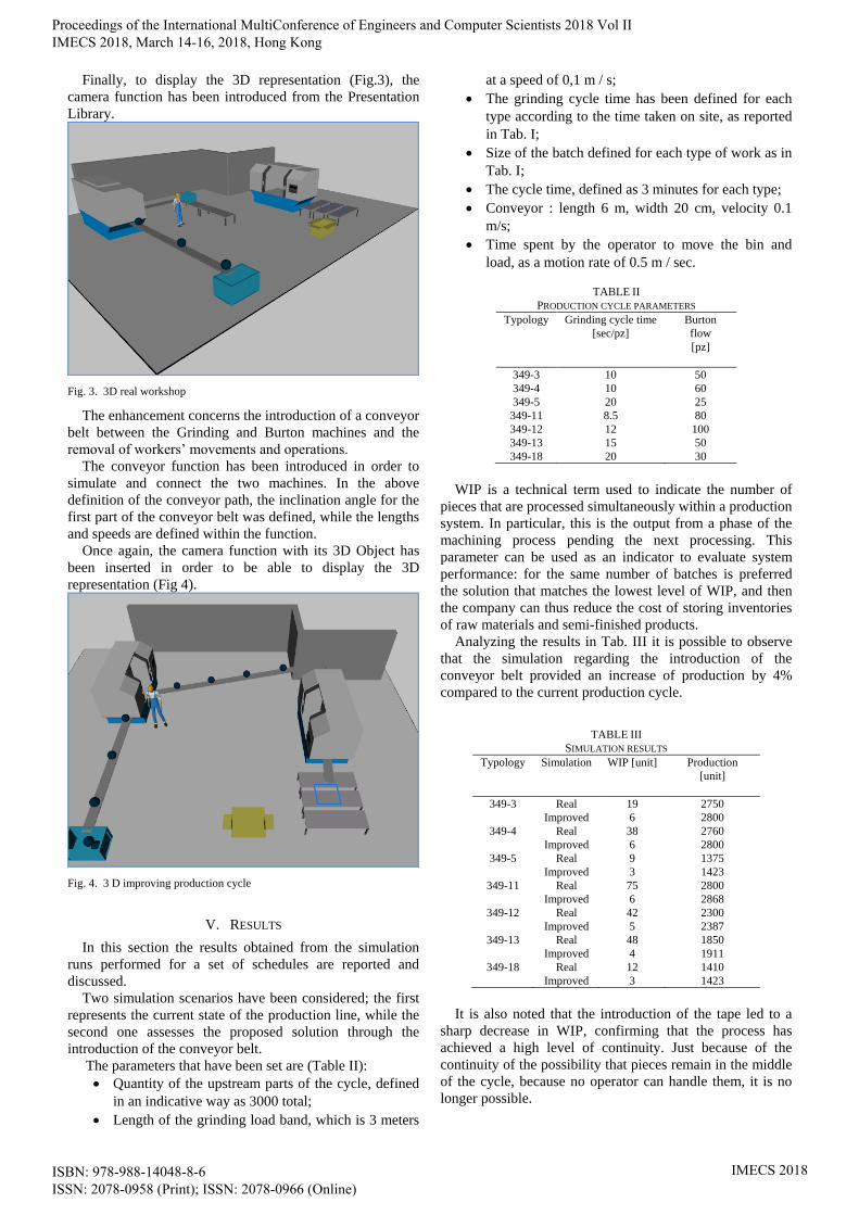
The enhancement concerns the introduction of a conveyor
belt between the Grinding and Burton machines and the
removal of workers’ movements and operations.
The conveyor function has been introduced in order to
simulate and connect the two machines. In the above
definition of the conveyor path, the inclination angle for the
first part of the conveyor belt was defined, while the lengths
and speeds are defined within the function.
Once again, the camera function with its 3D Object has
been inserted in order to be able to display the 3D
representation (Fig 4).
Fig. 4. 3 D improving production cycle
V. RESULTS
In this section the results obtained from the simulation
runs performed for a set of schedules are reported and
discussed.
Two simulation scenarios have been considered; the first
represents the current state of the production line, while the
second one assesses the proposed solution through the
introduction of the conveyor belt.
The parameters that have been set are (Table II):
Quantity of the upstream parts of the cycle, defined
in an indicative way as 3000 total;
Length of the grinding load band, which is 3 meters
at a speed of 0,1 m / s;
The grinding cycle time has been defined for each
type according to the time taken on site, as reported
in Tab. I;
Size of the batch defined for each type of work as in
Tab. I;
The cycle time, defined as 3 minutes for each type;
Conveyor : length 6 m, width 20 cm, velocity 0.1
m/s;
Time spent by the operator to move the bin and
load, as a motion rate of 0.5 m / sec.
TABLE II
PRODUCTION CYCLE PARAMETERS
Typology Grinding cycle time
[sec/pz]
Burton
flow
[pz]
349-3 10 50
349-4 10 60
349-5 20 25
349-11 8.5 80
349-12 12 100
349-13 15 50
349-18 20 30
WIP is a technical term used to indicate the number of
pieces that are processed simultaneously within a production
system. In particular, this is the output from a phase of the
machining process pending the next processing. This
parameter can be used as an indicator to evaluate system
performance: for the same number of batches is preferred
the solution that matches the lowest level of WIP, and then
the company can thus reduce the cost of storing inventories
of raw materials and semi-finished products.
Analyzing the results in Tab. III it is possible to observe
that the simulation regarding the introduction of the
conveyor belt provided an increase of production by 4%
compared to the current production cycle.
TABLE III
SIMULATION RESULTS
Typology Simulation WIP [unit] Production
[unit]
349-3 Real 19 2750
Improved 6 2800
349-4 Real 38 2760
Improved 6 2800
349-5 Real 9 1375
Improved 3 1423
349-11 Real 75 2800
Improved 6 2868
349-12 Real 42 2300
Improved 5 2387
349-13 Real 48 1850
Improved 4 1911
349-18 Real 12 1410
Improved 3 1423
It is also noted that the introduction of the tape led to a
sharp decrease in WIP, confirming that the process has
achieved a high level of continuity. Just because of the
continuity of the possibility that pieces remain in the middle
of the cycle, because no operator can handle them, it is no
longer possible.
Proceedings of the International MultiConference of Engineers and Computer Scientists 2018 Vol II IMECS 2018, March 14-16, 2018, Hong Kong
ISBN: 978-988-14048-8-6 ISSN: 2078-0958 (Print); ISSN: 2078-0966 (Online)
IMECS 2018

VI. CONCLUSION
The study at the mechanical company has made it
possible to verify that in a serial production the continuity of
flow is a critical factor and that eliminating any accidental
interruption is in itself a sensible improvement factor. The
solution found, based on the adoption of simple
electromechanical equipment such as a conveyor belt,
allows optimizing the work of the staff in increments both in
terms of physical effort and control over the product.
The adoption of modeling and simulation software like
AnyLogic has allowed us to analyze the results of the
modifications studied without having to realize them in
reality and thus without significant economic impacts due to
the cost of implementation. This solution can be considered
as a real application of DT. The DT can be used for a
number of use cases and in several phases of the object’s
lifecycle [11]. Although the idea of the DT can be applied to
nearly every real world entity, the presented approach
focuses on its application in the industrial context. The
usefulness of the DT is not a matter of quantity of data, i.e.
it is not productive to try to collect all the information about
everything or to be as precise as possible [12]. Instead, a
very clear view on what information is necessary for the
given tasks (and which is not) is the basis for creating a
powerful DT, both efficient and comprehensive at the same
time.
From the analysis of the results obtained it is noted that
the production remains almost unchanged as that who
"rules" the production cycle are the times of the start-up
cycle machine - grinding - which can’t be further improved;
however, the introduction of automation such as conveyor
belt has ensured the continuity of machining by making the
Burton power completely unblocked by the action of an
operator. In the original version, this could not be as safe
and timely as it had to be run by an operator. Additionally,
this change has allowed the WIP to be eliminated and hence
the possibility that some pieces remain in the middle of the
cycle.
Optimizing the work time of the worker, relieved of the
job of transporting parts from one machine to another,
allows you to pay more attention to other tasks such as
quality controls with obvious improvement in production
standards. The insertion of an acoustic/luminous alarm
system in case of anomalies in the operation of the tape
would make the system even more powerful and secure.
In summary, making the cycle in the long run this will be
even more productive as a result of the factors just analyzed
and even the work of the employee becomes more valuable
when it is now more oriented towards relevant actions such
as the quality control of the pieces produced, rather than on
activities mainly based on porterage.
REFERENCES
[1] K. Zhou, T. Liu, and L. Zhou, “Industry 4.0: Towards future
industrial opportunities and challenges,” 2015 12th Int. Conf.
Fuzzy Syst. Knowl. Discov. FSKD 2015, pp. 2147–2152,
2016.
[2] E. Negri, L. Fumagalli, and M. Macchi, “A Review of the
Roles of Digital Twin in CPS-based Production Systems,”
Procedia Manuf., vol. 11, 2017.
[3] S. Choi, G. Kang, C. Jun, J. Y. Lee, and S. Han, “Cyber-
physical systems: A case study of development for
manufacturing industry,” Int. J. Comput. Appl. Technol., vol.
55, no. 4, 2017.
[4] B. Rodič, “Industry 4.0 and the New Simulation Modelling
Paradigm,” Organizacija, vol. 50, no. 3, 2017.
[5] P. Svejvig and P. Andersen, “Rethinking project
management: A structured literature review with a critical
look at the brave new world,” Int. J. Proj. Manag., vol. 33,
no. 2, pp. 278–290, 2015.
[6] F. Almada-Lobo, “The Industry 4.0 revolution and the future
of Manufacturing Execution Systems (MES),” J. Innov.
Manag., vol. 3, no. 4, p. 17, 2016.
[7] M. Demartini, F. Tonelli, L. Damiani, and R. Revetria,
“Digitalization of Manufacturing Execution Systems : the
core technology for realizing future Smart Factories,” in
XXII edition of the Summer School “Francesco Turco,”
2017.
[8] T. H.-J. Uhlemann, C. Lehmann, and R. Steinhilper, “The
Digital Twin: Realizing the Cyber-Physical Production
System for Industry 4.0,” in Procedia CIRP, 2017, vol. 61.
[9] R. Rosen, G. Von Wichert, G. Lo, and K. D. Bettenhausen,
“About the importance of autonomy and digital twins for the
future of manufacturing,” IFAC-PapersOnLine, vol. 28, no.
3, pp. 567–572, 2015.
[10] S. Weyer, T. Meyer, M. Ohmer, D. Gorecky, and D. Zühlke,
“Future Modeling and Simulation of CPS-based Factories:
an Example from the Automotive Industry,” IFAC-
PapersOnLine, vol. 49, no. 31, 2016.
[11] S. Konstantinov, M. Ahmad, K. Ananthanarayan, and R.
Harrison, “The Cyber-physical E-machine Manufacturing
System: Virtual Engineering for Complete Lifecycle
Support,” in Procedia CIRP, 2017, vol. 63.
[12] K. Reifsnider and P. Majumdar, “Multiphysics stimulated
simulation digital twin methods for fleet management,” in
Collection of Technical Papers -
AIAA/ASME/ASCE/AHS/ASC Structures, Structural
Dynamics and Materials Conference, 2013.
Proceedings of the International MultiConference of Engineers and Computer Scientists 2018 Vol II IMECS 2018, March 14-16, 2018, Hong Kong
ISBN: 978-988-14048-8-6 ISSN: 2078-0958 (Print); ISSN: 2078-0966 (Online)
IMECS 2018