simulation and optimization of metal forming processes
TRANSCRIPT
Precision Forging Group© Copyright Engineering Research Center for Net Shape Manufacturing, 2008
ERCNSM
1
Simulation and Optimization of Metal Forming Processes
New Applications and Challenges
19. Umformtechnisches Kolloquium Hannover: 27/28 Februar 2008
Manas Shirgaokar, Graduate Research Associate([email protected])
Ajay Yadav, Graduate Research Associate([email protected])
Dr. Taylan Altan, Professor & Director([email protected])
Engineering Research Center for Net Shape Manufacturing, ERC/NSMThe Ohio State University, Columbus, Ohio
http://www.ercnsm.org
Precision Forging Group© Copyright Engineering Research Center for Net Shape Manufacturing, 2008
ERCNSMOutline
• Need for Process Simulation in Metal Forming.
• Requirements for Process Simulation.
– Material Properties.
– Interface Friction Conditions.
• Selected Process Modeling Case Studies.
– Precision Cold, Warm and Hot Forging.
– Stamping.
• Summary and Concluding Remarks.
2
Precision Forging Group© Copyright Engineering Research Center for Net Shape Manufacturing, 2008
ERCNSM
3
Improvement of Profitability
Steps to increase profitability in global competition:– Increase material utilization (reduction of scrap, flash, etc.).
– Reduce defects and scrap rate.
– Increase die service life.
– Increase utilization rate of forming equipment.
– Process optimization by use of computer aided engineering (CAE) tools.
– Increase automation and decrease labor content.
– Efficient information management.
– Training of personnel/access to advanced technology.
Precision Forging Group© Copyright Engineering Research Center for Net Shape Manufacturing, 2008
ERCNSM
4
Process Simulation using CAE
Main Goal: Reduce part development time and cost, and increase quality and productivity.
Specific Goals:– Optimization of blank-holder force and blank geometry in stamping.
– Optimization of internal pressure vs. axial feed in tube hydroforming.
– Preform and die design optimization for improved material yield in hot forging.
– Die material selection and process design for improved die life in warm and hot forging.
– Prediction of internal defects and part quality in cold forging.
Precision Forging Group© Copyright Engineering Research Center for Net Shape Manufacturing, 2008
ERCNSM
Process Modeling Requirements-Material Properties-
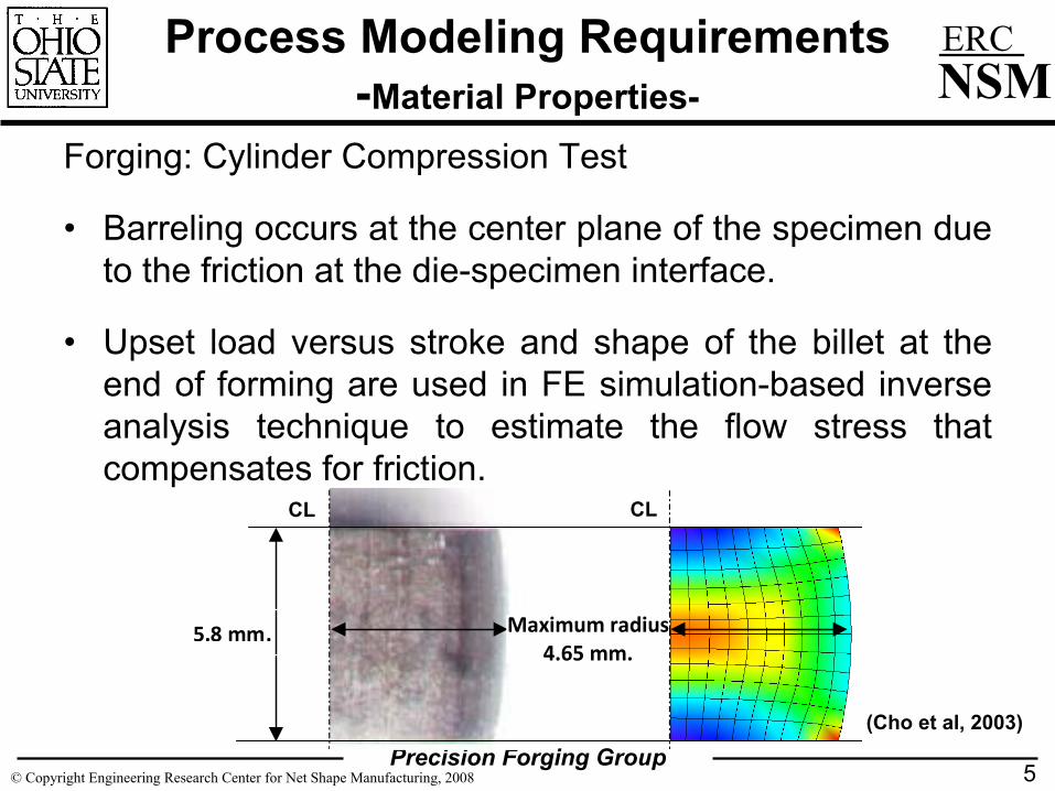
Forging: Cylinder Compression Test
• Barreling occurs at the center plane of the specimen due to the friction at the die-specimen interface.
• Upset load versus stroke and shape of the billet at the end of forming are used in FE simulation-based inverse analysis technique to estimate the flow stress that compensates for friction.
5
5.8mm. Maximum radius4.65mm.
Maximum radius4.65 mm.
5.8 mm.
(Cho et al, 2003)
CLCL
Precision Forging Group© Copyright Engineering Research Center for Net Shape Manufacturing, 2008
ERCNSM
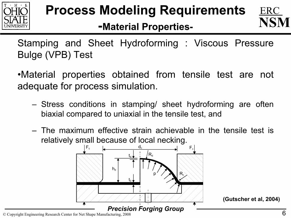
Stamping and Sheet Hydroforming : Viscous Pressure Bulge (VPB) Test
•Material properties obtained from tensile test are not adequate for process simulation.
– Stress conditions in stamping/ sheet hydroforming are often biaxial compared to uniaxial in the tensile test, and
– The maximum effective strain achievable in the tensile test is relatively small because of local necking.
6
Process Modeling Requirements-Material Properties-
phd
dc
td
t0
Rc
Rd
Fc Fc
(Gutscher et al, 2004)
Precision Forging Group© Copyright Engineering Research Center for Net Shape Manufacturing, 2008
ERCNSM
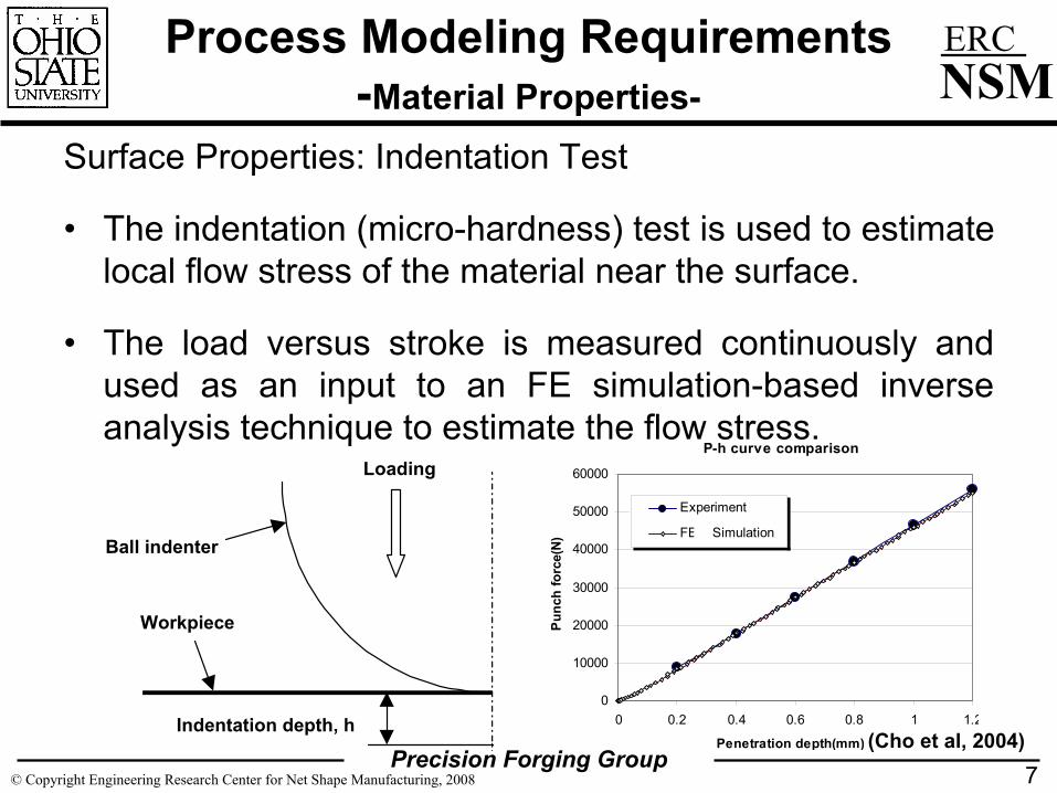
Surface Properties: Indentation Test
• The indentation (micro-hardness) test is used to estimate local flow stress of the material near the surface.
• The load versus stroke is measured continuously and used as an input to an FE simulation-based inverse analysis technique to estimate the flow stress.
7
Process Modeling Requirements-Material Properties-
Indentation depth, h
Loading
Ball indenter
Workpiece
P-h curve comparison
0
10000
20000
30000
40000
50000
60000
0 0.2 0.4 0.6 0.8 1 1.2
Penetration depth(mm)
Pun
ch fo
rce(
N)
Experiment
FEM SimulationA
(Cho et al, 2004)
Precision Forging Group© Copyright Engineering Research Center for Net Shape Manufacturing, 2008
ERCNSM
Process Modeling Requirements-Interface Friction Conditions in Forging-
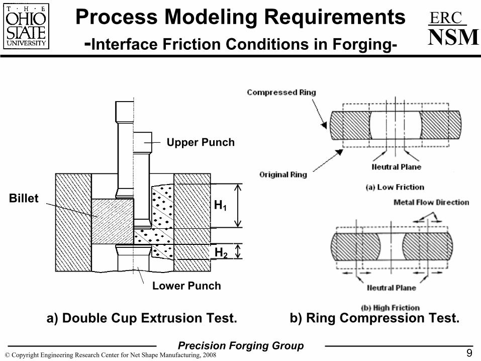
Forging: Ring Compression Test (RCT) and Double Cup Extrusion Test (DCET)
•The DCET is used to evaluate lubricants in processes that involve high contact pressures and surface expansion. Lubricants are evaluated and ranked on the basis of the cup height ratio.
•The RCT is mainly used to test lubricants in cold heading and warm/hot forging due to its simplicity. Lubricants are evaluated and ranked on the basis of the change in ring inner diameter for different height reductions.
•The friction factor in both cases is estimated using calibration curves developed through FE analysis.
8
Precision Forging Group© Copyright Engineering Research Center for Net Shape Manufacturing, 2008
ERCNSM
Process Modeling Requirements-Interface Friction Conditions in Forging-
9
Billet
Upper Pu
Lower Punch
Upper Punch
Lower Punch
H2
H1
a) Double Cup Extrusion Test. b) Ring Compression Test.
Precision Forging Group© Copyright Engineering Research Center for Net Shape Manufacturing, 2008
ERCNSM
Process Modeling Requirements-Interface Friction Conditions in Stamping-
Stamping: Deep Drawing Test
• This test emulates the interface condition that exists in production, both in the flange and in the punch.
• Circular cups are drawn from a blank of fixed draw ratio but with different blank holder force until they fracture. The largest blank holder force that can be used to draw the cup without failure indicates the performance of the lubricant.
• The higher is the blank holder force, the better is the performance of the lubricant in the test. Also, a large punch force indicates bad performance of the lubricant.
10
Precision Forging Group© Copyright Engineering Research Center for Net Shape Manufacturing, 2008
ERCNSM
Process Modeling Requirements-Interface Friction Conditions in Stamping-
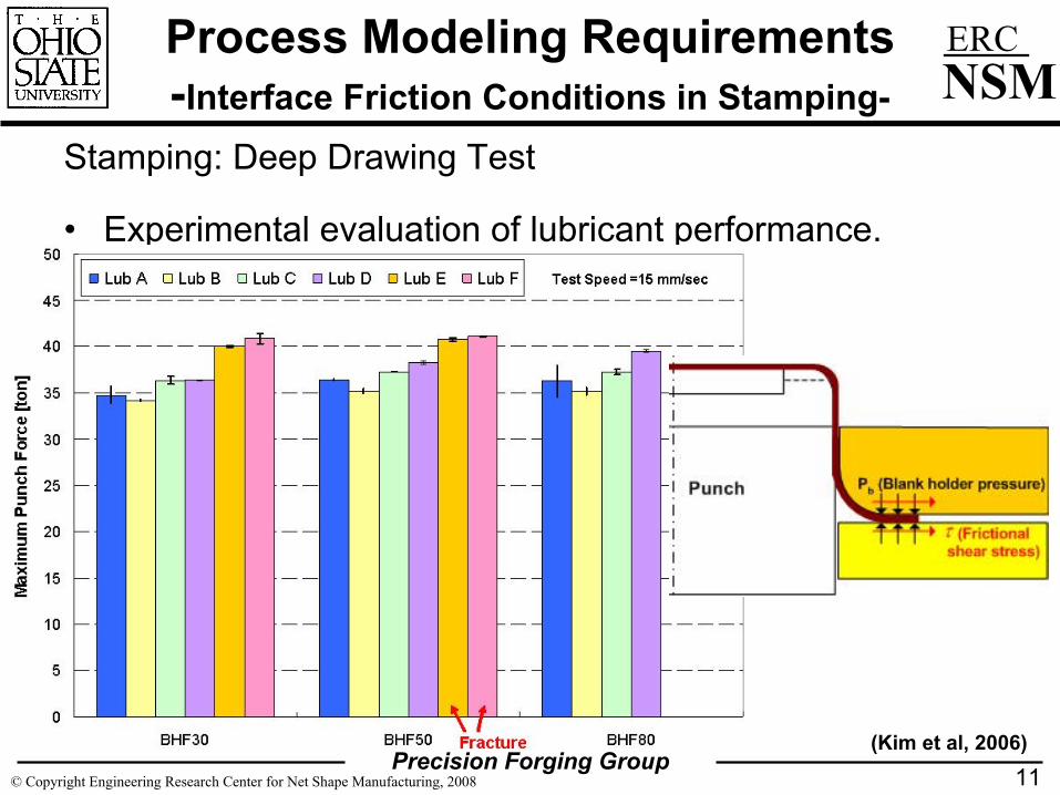
Stamping: Deep Drawing Test
• Experimental evaluation of lubricant performance.
11(Kim et al, 2006)
Precision Forging Group© Copyright Engineering Research Center for Net Shape Manufacturing, 2008
ERCNSM
Process Modeling Applications-Incremental Forming-
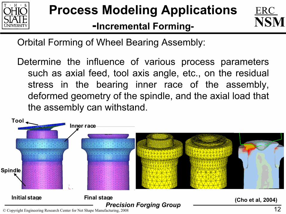
Orbital Forming of Wheel Bearing Assembly:
Determine the influence of various process parameters such as axial feed, tool axis angle, etc., on the residual stress in the bearing inner race of the assembly, deformed geometry of the spindle, and the axial load that the assembly can withstand.
12
Initial stage Final stage
Tool Inner race
Spindle
(Cho et al, 2004)
Precision Forging Group© Copyright Engineering Research Center for Net Shape Manufacturing, 2008
ERCNSM
Process Modeling Applications-Microforming of Medical Devices-
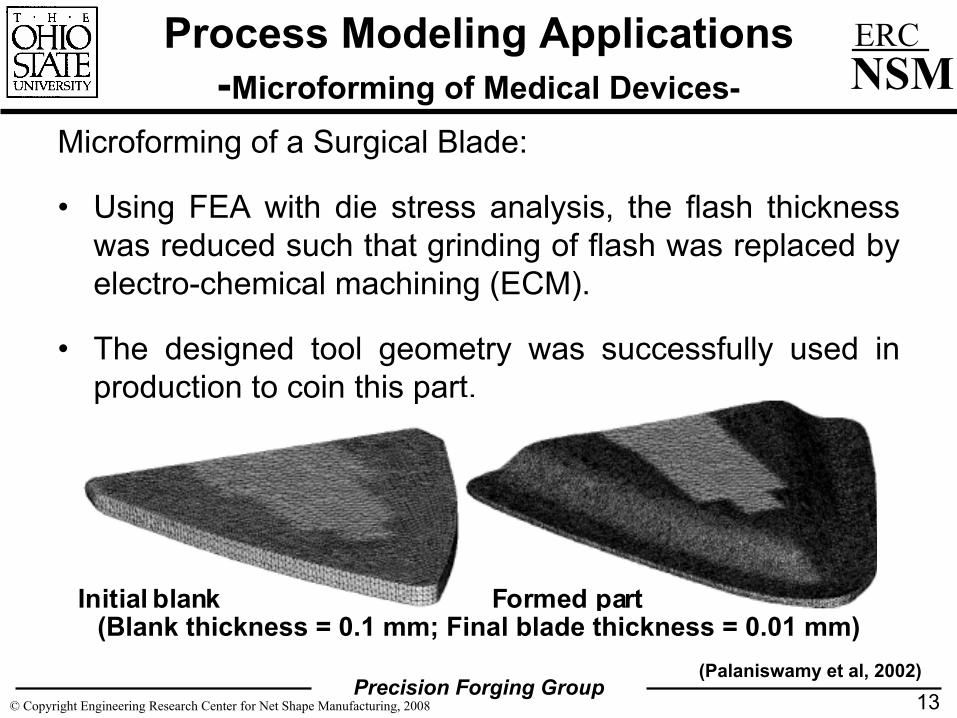
Microforming of a Surgical Blade:
• Using FEA with die stress analysis, the flash thickness was reduced such that grinding of flash was replaced by electro-chemical machining (ECM).
• The designed tool geometry was successfully used in production to coin this part.
13
Formed partInitial blank (Blank thickness = 0.1 mm; Final blade thickness = 0.01 mm)
(Palaniswamy et al, 2002)
Precision Forging Group© Copyright Engineering Research Center for Net Shape Manufacturing, 2008
ERCNSM
Process Modeling Applications-Material Yield Improvement in Hot Forging-
14
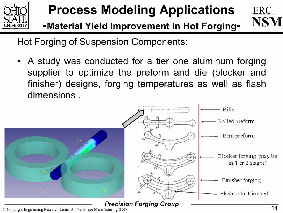
Hot Forging of Suspension Components:
• A study was conducted for a tier one aluminum forging supplier to optimize the preform and die (blocker and finisher) designs, forging temperatures as well as flash dimensions .
Precision Forging Group© Copyright Engineering Research Center for Net Shape Manufacturing, 2008
ERCNSM
Process Modeling Applications-Material Yield Improvement in Hot Forging-
15
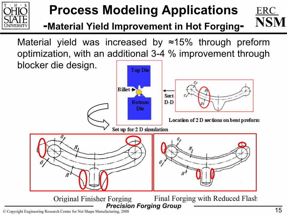
Material yield was increased by ≈15% through preform optimization, with an additional 3-4 % improvement through blocker die design.
Original Finisher Forging Final Forging with Reduced Flash
Precision Forging Group© Copyright Engineering Research Center for Net Shape Manufacturing, 2008
ERCNSM
Process Modeling Applications-Improvement of Die Life in Forging-
Die Wear Study (Forging Industry Association):
• Main Goal: Prediction and improvement of die life in warm and hot forging processes through combination of FEA and shop-floor trials under production conditions.
• Specific Goals:
– Identification of interface conditions at start-up and steady-state.
– Selection and comparison of die materials through FEA.
– Design of shrink-fitted dies with ceramic and carbide inserts accounting for thermal expansion during preheating and forging.
– Preform and die design for reduction of die-workpiece contact time and relative sliding.
16
Precision Forging Group© Copyright Engineering Research Center for Net Shape Manufacturing, 2008
ERCNSM
Process Modeling Applications-Improvement of Die Life in Forging-
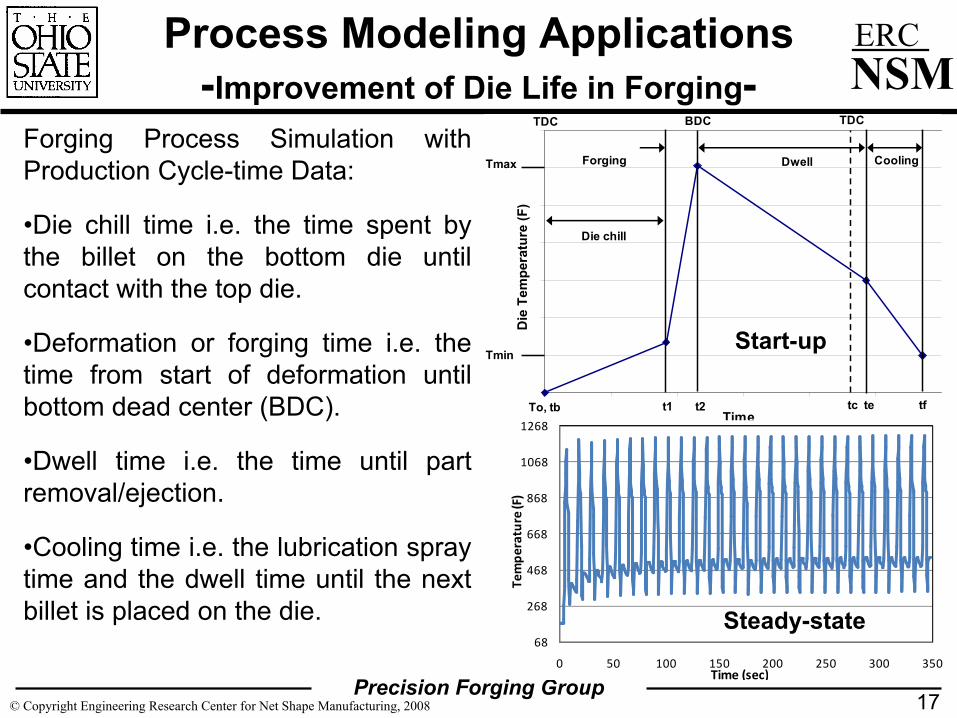
Forging Process Simulation with Production Cycle-time Data:
•Die chill time i.e. the time spent by the billet on the bottom die until contact with the top die.
•Deformation or forging time i.e. the time from start of deformation until bottom dead center (BDC).
•Dwell time i.e. the time until part removal/ejection.
•Cooling time i.e. the lubrication spray time and the dwell time until the next billet is placed on the die.
17
300
400
500
600
700
800
900
1000
0 0.2 0.4 0.6 0.8 1 1.Time
Die
Tem
pera
ture
(F)
Die chill
Forging Dwell Cooling
To, tb
TDC TDCBDC
t1 t2 tetc
Tmax
Tmin
tf
68
268
468
668
868
1068
1268
0 50 100 150 200 250 300 350
Tem
pera
ture
(F)
Time (sec)
Steady-state
Start-up
Precision Forging Group© Copyright Engineering Research Center for Net Shape Manufacturing, 2008
ERCNSM
Process Modeling Applications-Improvement of Die Life in Forging-
• Scrap rates were reduced by 50% in a hot forging process through improved preform design and die material selection developed by FEA of the forging process (Impact Forge, USA).
• Effect of die material properties on thermal fatigue performance was investigated in order to screen alternative die materials.
• Loss of compressive stress in a shrink-fit die was determined through simulation of die heating and multiple-cycle forging (American Axle, USA).
• The application of matrix-high speed steels is being explored through production trials (Hirschvogel, USA).
18
Precision Forging Group© Copyright Engineering Research Center for Net Shape Manufacturing, 2008
ERCNSM
Process Modeling Applications-Blank Design in Stamping-
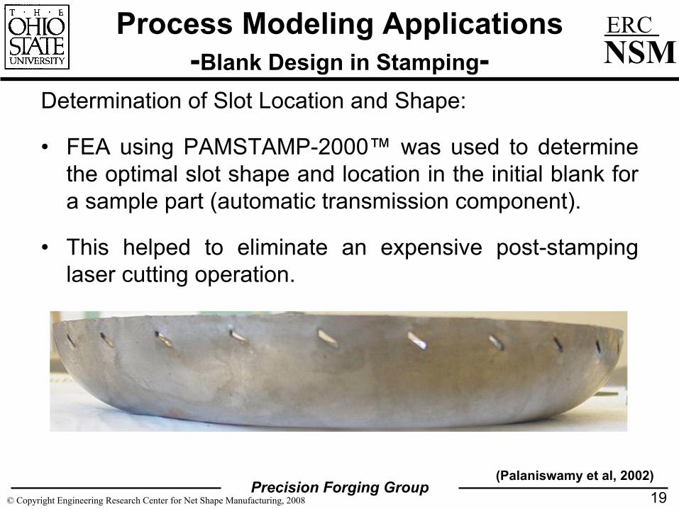
Determination of Slot Location and Shape:
• FEA using PAMSTAMP-2000™ was used to determine the optimal slot shape and location in the initial blank for a sample part (automatic transmission component).
• This helped to eliminate an expensive post-stamping laser cutting operation.
19(Palaniswamy et al, 2002)
Precision Forging Group© Copyright Engineering Research Center for Net Shape Manufacturing, 2008
ERCNSM
Process Modeling Applications-Blank-holder Force Control-
Programming a Multipoint Cushion System:
• As part of a USCAR project, an optimization technique was developed coupled with FE codes to estimate the blank holder force that is variable in space and constant in stroke.
• The developed software was used to predict the blank holder force required to form a full size automotive panel (Lift-gate – inner) from three different materials (aluminum alloy A6111-T4, t=1.0 mm, BH210, t=0.8 mm and DP500 t=0.8 mm).
20(Palaniswamy et al, 2002)

Precision Forging Group© Copyright Engineering Research Center for Net Shape Manufacturing, 2008
ERCNSM
Process Modeling Applications-Blank-holder Force Control-
21
Precision Forging Group© Copyright Engineering Research Center for Net Shape Manufacturing, 2008
ERCNSM
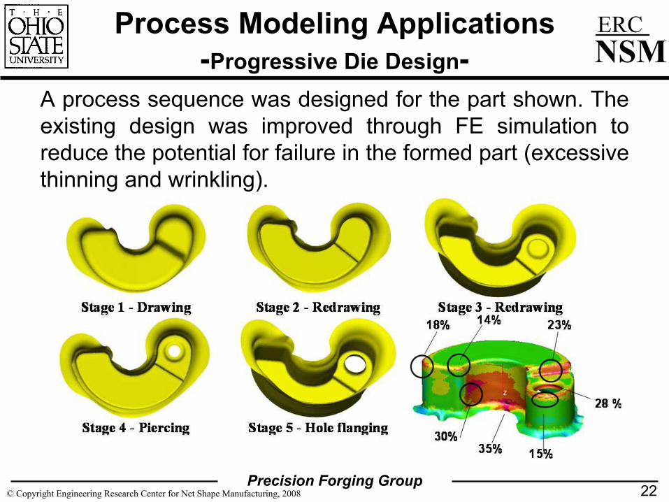
Process Modeling Applications-Progressive Die Design-
A process sequence was designed for the part shown. The existing design was improved through FE simulation to reduce the potential for failure in the formed part (excessive thinning and wrinkling).
22

Precision Forging Group© Copyright Engineering Research Center for Net Shape Manufacturing, 2008
ERCNSM
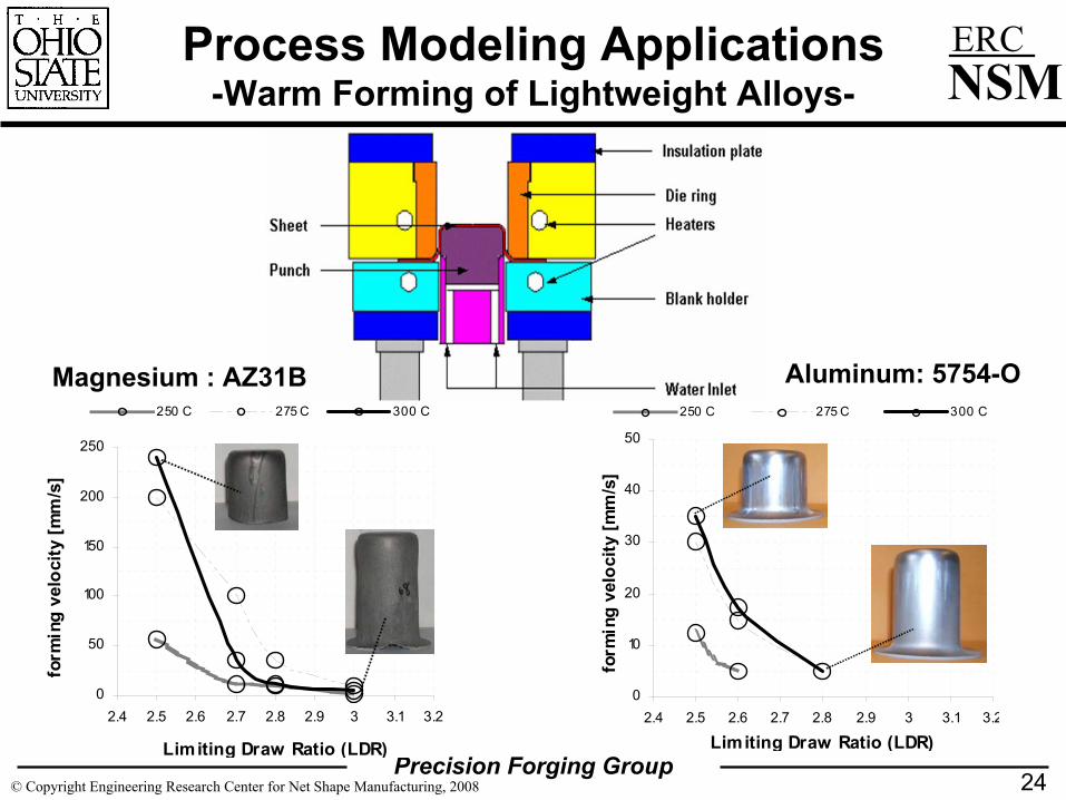
Process Modeling Applications-Warm Forming of Lightweight Alloys-
Warm sheet forming of magnesium and aluminum alloys
• A study was conducted, in co-operation with Aida-America, to investigate deep drawing of a magnesium alloy, an aluminum alloy and austenitic stainless steel at elevated temperature.
• The sheet was heated in the tooling and then formed at different speeds using a servo motor driven press that allows infinite degrees of freedom to control the ram motion and speed.
• Maximum draw ratio of 3.0 can be obtained at 300° C with maximum ram velocities of 2 mm/sec and 5 mm/sec for AZ31B and AL5754-O sheet material, respectively.
23
Precision Forging Group© Copyright Engineering Research Center for Net Shape Manufacturing, 2008
ERCNSM
Process Modeling Applications-Warm Forming of Lightweight Alloys-
24
0
50
100
150
200
250
2.4 2.5 2.6 2.7 2.8 2.9 3 3.1 3.2
Limiting Draw Ratio (LDR)
form
ing
velo
city
[mm
/s]
250 C 275 C 300 C
0
10
20
30
40
50
2.4 2.5 2.6 2.7 2.8 2.9 3 3.1 3.2
Limiting Draw Ratio (LDR)
form
ing
velo
city
[mm
/s]
250 C 275 C 300 C
Aluminum: 5754-OMagnesium : AZ31B
Precision Forging Group© Copyright Engineering Research Center for Net Shape Manufacturing, 2008
ERCNSM
25
Summary
• Process modeling through FE simulation is an essential tool in modern metal forming to reduce the development cost and time.
• Continuous development of FE software for metal forming has increased its scope to cover a large range of metal forming processes including warm sheet forming and metal cutting.
• In this paper an overview is given on the application of FE simulation for industrially relevant practical problems.
Precision Forging Group© Copyright Engineering Research Center for Net Shape Manufacturing, 2008
ERCNSMReferences
• H.Cho, G.Ngaile, T.Altan, 2003, “Simultaneous determination of flow stress and interface friction by finite element based inverse analysis technique”, Annals of CIRP, Vol 52, pp 221-224.
• G. Gutscher, H.C. Wu, G.Ngaile, T.Altan, 2004, “Determination of flow stress for sheet metal forming using the viscous pressure bulge (VPB) test”, Journal of Materials Processing Technology Vol. 146, pp 1-7.
• H. Cho, N.Kim, T.Altan, 2004, “Finite element based inverse analysis for determination of flow stress for determination of flow stress data and friction”,ERC report no: F/ERC/NSM-04-R-20, The Ohio State University, Columbus, Ohio.
• H. Kim, J. Sung, R. Sivakumar, T. Altan, 2006, “Evaluation of stamping lubricants using deep drawing test”, accepted for publication in the International Journal for Machine Tools and Manufacture.
• H.Cho, G. Ngaile, T. Altan, 2004, “3D finite element analysis of orbital forming and inverse analysis for determination of flow stress of the workpiece”, Materials Processing and Design: Modeling, Simulation and Application, NUMIFORM 2004, pp 1502 –1507.
• H.Palaniswamy, G.Ngaile, T.Altan, 2002, “Coining of surgical slit knife”, ERC Report no: S/ERC/NSM –02-16, The Ohio State University, Columbus, Ohio.
26
Precision Forging Group© Copyright Engineering Research Center for Net Shape Manufacturing, 2008
ERCNSMReferences
• H.Palaniswamy, N.Jain, T.Altan, 2002, “Design of optimal slot shape and blank shape using finite element analysis”, ERC/NSM Report no. ERC/NSM – 02 –102, The Ohio State University, Columbus, Ohio.
• H. Palaniswamy, M. Braedel, A. Thandapani, T. Altan, 2006,” Optimal programming of multipoint cushion systems in sheet metal forming”, Annals of CIRP, Vol 55/1, pp 249-254.
• S. Kaya, G. Spampinato, T. Altan, 2007, “An Experimental Study on Non-Isothermal Deep Drawing Process Using Aluminum and Magnesium Alloys”, (in review –, Journal of Manufacturing Science and Engineering).
27