simulation by finite elements of bone remodelling after implantation of...
TRANSCRIPT

9
Simulation by Finite Elements of Bone Remodelling After
Implantation of Femoral Stems
Luis Gracia et al.* Engineering and Architecture Faculty, University of Zaragoza,
Spain
1. Introduction
Degenerative osteoarthritis and rheumatoid diseases lead to a severe destruction of the hip joint and to an important functional disability of the patient. Several attempts by many surgeons were documented, in the history of Orthopedic Surgery, to restore an adequate function of the pathologic joint. All these attempts failed due to the use of inadequate materials or due to technical problems.
In the past 20th century, during the sixties, a successful replacement of a pathologic hip joint was finally achieved. It was the first arthroplasty of the hip providing a good functional outcome. This new technique was described by Charnley in 1961 (Charnley, 1961). Two materials were then introduced in the orthopedic surgery, the polyethylene and the polymethyl methacrylate. This later is known as bone cement, and allowed a good fixation of the prosthetic implants into the femoral canal and the pelvic acetabulum. This technique represented one of the most important advances in the Orthopedic Surgery during the 20th century.
Based on the original model developed by Charnley, total cemented hip implants have been improved with new materials and prosthetic designs. The most important advances have been described in the cements and cementation techniques (Mulroy & Harris, 1990; Noble et al., 1998; Reading et al., 2000), and in the sterilization and manufacture of the prosthetic polyethylene (Medel et al., 2004; Urries et al., 2004; D’Antonio et al, 2005; Oral et al., 2006; Faris et al., 2006; Gordon et al., 2006; Wolf et al., 2006). Nevertheless, the original stem design of Charnley remains unaltered and fully operational.
First generation cemented prosthesis, inserted by manual techniques (first generation cement fixation), were associated with high rates of aseptic loosening and mechanical failures (Olsson et al., 1981; Stauffer, 1982; Harris et al., 1982; Halley & Wroblewski, 1986;
*Elena Ibarz1, José Cegoñino1, Antonio Lobo-Escolar2,3, Sergio Gabarre1, Sergio Puértolas1, Enrique López1, Jesús Mateo2,3, Antonio Herrera2,3 1Engineering and Architecture Faculty, University of Zaragoza, Spain 2Medicine School, University of Zaragoza, Spain 3Miguel Servet University Hospital, Zaragoza, Spain
www.intechopen.com

Finite Element Analysis – From Biomedical Applications to Industrial Developments
218
Mohler et al., 1995). Cementless implants were developed as an alternative for young and active patients. In the cementless hip replacement, there exists a direct contact between the prosthesis and the bone, and a primary rigid fixation of the implant is required for a proper outcome. This is obtained with a press-fit fixation technique, where for a perfect adjustment the implant is slightly larger than the surrounding bone.
In the postoperative first months, a secondary fixation is achieved when the surrounding bone ingrowths into the implant (bone ingrowth fixation) (Herrera et al., 2001). The designs and materials of cementless femoral stems have evolved from the original, in order to obtain more physiologic load transmissions and a better fixation. In the earlier femoral stem models, the goal was to achieve a great fixation into the femoral diaphysis. Examples of these models were AML and Lord femoral implants, with large porous coating surfaces along their diaphyseal areas. Over the years, the osteointegration rates of these large porous coating stems were found to be only around 35% (Hennessy et al., 2009). A strong devitalization of the proximal femoral metaphysis, and the proximal diaphysis in the case of Lord stems, was also demonstrated with the use of these implants (Grant & Nordsletten, 2004).
These prostheses were found to be stable in the long term, but their distal diaphyseal fixation produced a removal of normal stress on the proximal bone, being the main cause of the proximal devitalization. This situation is known as stress shielding. New models were then designed taking into account not only mechanical concepts but also bone biology. In order to preserve proximal bone stock, modern femoral stems have a lesser diameter, and are coated only proximally with hydroxyapatite. Despite these improvements, the stress shielding is still found in the long term in all total hip replacements.
Bone is living tissue undergoes a constant process of replacement of its structure, characterized by bone resorption and new bone formation, without changing their morphology. This process is called bone remodeling. On the other hand, bone adapts its structure, according to Wolff's Law, to the forces and biomechanical loads that receives (Buckwalter et al., 1995). In a normal hip joint, loads from the body are transmitted to the femoral head, then to the medial cortical bone of femoral neck towards the lesser trochanter, where they are distributed by the diaphyseal bone (Radin, 1980).
Body weight is transmitted to the femoral head in a normal hip joint. This load goes through the cortical bone of the medial femoral neck down to the lesser trochanter, where it is distributed to the diaphyseal bone. The implantation of a cemented or cementless femoral stem involves a clear alteration of the physiological load transmission. Loads are now passed through the prosthetic stem in a centripetal way, from the central marrow cavity to cortical bone (Herrera & Panisello 2006). This alteration of the normal biomechanics of the hip results in a phenomenon called adaptive bone remodeling (Huiskes et al, 1989), which means that physiological remodeling takes place in a new biomechanical environment.
The implantation of a cemented or cementless femoral stem produced a clear alteration of the physiological transmission of loads, as these are now passed through the prosthetic stem, in a centripetal way, from the central marrow cavity to the cortical bone (Marklof et al., 1980). These changes of the normal biomechanics of the hip bone leads to a phenomenon called adaptive remodeling (Huiskes et al., 1989), since bone has to adapt to the new biomechanical situation. Remodeling is a multifactorial process dependent on both mechanical and biological factors. Mechanical factors are related to the new distribution of
www.intechopen.com

Simulation by Finite Elements of Bone Remodelling After Implantation of Femoral Stems
219
loads caused by implantation of the prosthesis in the femur, the physical characteristics of the implant (size, implant design and alloy), and the type of anchoring in the femur: metaphyseal, diaphyseal, hybrid, etc. (Summer & Galante, 1992; Sychter & Engh, 1996; Rubash et al., 1998; McAuley et al., 2000; Gibson et al., 2001; Glassman et al., 2001). Biologics are related to age and weight of the individual, initial bone mass, quality of primary fixation and loads applied to the implant. Of these biological factors, the most important is initial bone mass (Sychter & Engh, 1996).
Orthopedic surgeons have taken many years to learn the biomechanics and biology of bone tissue. We began to focus on these sciences when long-term revisions of cemented and cementless femoral stems proved extensive atrophy of the femoral cortical bone, a pathological phenomenon caused by stress-shielding. Different models of cementless stems have tried to achieve perfect load transfer to the femur, mimicking the physiological transmission from the femoral calcar to the femoral shaft. The main objective was to avoid stress-shielding, since in absence of physiological transmission of loads, and lack of mechanical stimulus in this area, causes proximal bone atrophy.
Cemented stem fixation is achieved by the introduction of cement into bone, forming a bone-cement interface. Inside the cement mantle a new interface is made up between cement and stem. It might seem that the cement mantle enables better load distribution in the femur; however the design, material and surface of prostheses, play an important role in transmission and distribution of charges, influencing bone remodeling (Ramaniraka et al., 2000; Li et al., 2007)
Long-term follow-up of different models of cementless stems have shown that this is not achieved, and to a greater or lesser extent the phenomenon of stress-shielding is present in all the models, and therefore the proximal bone atrophy. It is interesting to know, in cemented stems, not only the stress-shielding and subsequent proximal bone atrophy, but also the long-term behavior of cement-bone and stem-cement interfaces. This requires long-term studies monitoring the different models of stems.
Research in different fields concerning Orthopaedic Surgery and Traumatology requires a methodology that allows, at the same time, a more economic approach and the possibility of reproducing in an easy way different situations. Such a method could be used as a guide for research on biomechanics of the locomotor system, both in healthy and pathologic conditions, along with the study of performance of different prostheses and implants. To that effect, the use of simulation models, introduced in the field of Bioengineering in recent years, can undoubtedly mean an essential tool to assess the best clinical option, provided that it will be accurate enough in the analysis of specific physiological conditions concerning certain pathology.
Finite element (FE) simulation has proved to be specially suitable in the study of the behaviour of any physiological unit, despite its complexity. Nowadays, it has become a powerful tool in the field of Orthopaedic Surgery and Traumatology, helping the surgeons to have a better understanding of the biomechanics, both in healthy and pathological conditions. FE simulation let us know the biomechanical changes that occur after prosthesis or osteosynthesis implantation, and biological responses of bone to biomechanical changes. It also has an additional advantage in predicting the changes in the stress distribution around the implanted zones, allowing preventing future pathologies derived from an unsuitable positioning of the prostheses.
www.intechopen.com

Finite Element Analysis – From Biomedical Applications to Industrial Developments
220
In this sense, finite element simulation has made easier to understand how the load is transmitted after the implantation of a femoral stem, and to predict how the stem impacts on the biomechanics in the long-term. Finite Element method can find out the long-term behavior and the impact on biomechanics of any prosthetic models. Up to now, long clinical trials, with a follow-up of at least 10 years, were needed to achieve this knowledge. Design of new femoral stem models is another important application of the Finite Element simulation. New models can be pre-tested by simulation in order to improve the design and minimize the stress-shielding phenomenon.
The Finite Element Method (FEM) was originally developed for solving structural analysis problems relating to Mechanics, Civil and Aeronautical Engineering. The paternity of this method is attributed to Turner, who published his first, historic, job in 1956 (Turner et al., 1956). In 1967, Zienkiewicz OC published the book “The finite element method in structural and continuum mechanics” (Zienkiewicz, 1967) which laid down mathematical basis of the method. Other fundamental contributions to the development of Finite Element Method (FEM) took place on dates nearest (Imbert, 1979; Bathe, 1982; Zienkiewicz & Morgan, 1983; Hughes, 1987).
2. Methodology for the finite element analysis of biomechanical systems
One of the most significant aspects of biomechanical systems is its geometric complexity, which greatly complicates the generation of accurate simulation models. Classic models just suffered from this lack of geometrical precision, present even in recent models, which challenged, in most studies, the validity of the results and their extrapolation to clinical settings.
Fig. 1. Real model of an implanted femur, 3D laser scanner and femoral stem
www.intechopen.com

Simulation by Finite Elements of Bone Remodelling After Implantation of Femoral Stems
221
Currently, there are methodologies developed over recent years that avoid such problems, allowing the generation of models with the desired precision in a reasonable time and cost is not excessive. Thus, the use of 3D laser scanners (Fig. 1) together with three-dimensional images obtained by CT allow making geometric models that combine high accuracy in the external form with an excellent definition of internal interfaces. The method requires not only appropriate software tools, capable of processing images, but also its compatibility with the programs used later to generate the finite element model. For example, in Fig. 1 (left) is shown the real model of an implanted femur and in Fig. 2 the result obtained by a three-dimensional laser scanner Roland Picza (after processing by Dr. Picza 3 and 3D Editor programs).
Fig. 2. 3D scanning of the implanted femur shown in Fig. 1
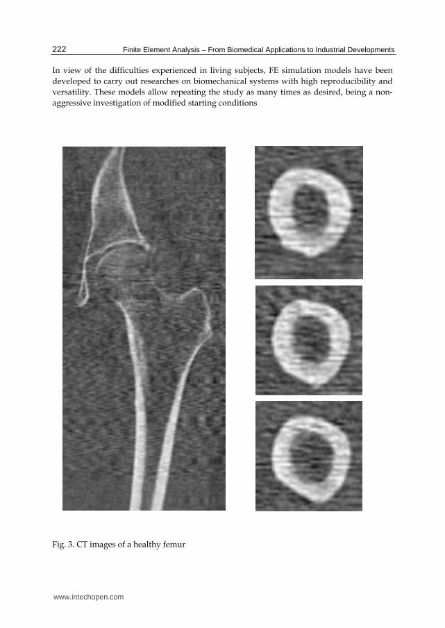
In these models, the characterization of the internal structure is made by 3D CT, from images like that shown in Figs. 3 and 4. An alternative to the above procedure is the use of 3D geometrical reconstruction programs, for example, MIMICS (Mimics, 2010). In any case, the final result is a precise geometrical model which serves as a basis for the generation of a finite elements mesh.
www.intechopen.com
Finite Element Analysis – From Biomedical Applications to Industrial Developments
222
In view of the difficulties experienced in living subjects, FE simulation models have been developed to carry out researches on biomechanical systems with high reproducibility and versatility. These models allow repeating the study as many times as desired, being a non-aggressive investigation of modified starting conditions
Fig. 3. CT images of a healthy femur
www.intechopen.com

Simulation by Finite Elements of Bone Remodelling After Implantation of Femoral Stems
223
Fig. 4. CT images of an implanted femur
However, work continues on the achievement of increasingly realistic models that allow putting the generated results and predictions into a clinical setting. To that purpose it is mainly necessary the use of meshes suitable for the particular problem, as regards both the type of elements and its size. It is always recommended to perform a sensitivity analysis of the mesh to determine the optimal features or, alternatively, the minimum necessary to achieve the required accuracy. In Fig. 5 is shown a FE mesh of healthy and implanted femurs, using tetrahedron type elements. It can be seen that the element size allows depicting, with little error, the geometry of the implanted femur, compared with Fig. 2.
www.intechopen.com

Finite Element Analysis – From Biomedical Applications to Industrial Developments
224
(a) (b)
Fig. 5. Meshing of proximal femur: a) Healthy femur; b) Implanted femur
A key issue in FE models is the interaction between the different constitutive elements of the biomechanical system, especially when it comes to conditions which are essential in the behaviour to be analyzed. The biomechanical behaviour of a cementless stem depends basically on the conditions of contact between the stem and bone, so that the correct simulation of the latter determines the validity of the model. In Fig 6 can be seen the stem-femur contact interface, defined by the respective surfaces and the frictional conditions needed to produce the press-fit which is achieved at surgery.
Finally, in FE simulation models is essential the appropriate characterization of the mechanical behaviour of the different materials, usually very complex. So, the bone exhibits an anisotropic behaviour with different responses in tension and compression (Fig. 7). Moreover, it varies depending on the bone type (cortical or cancellous) and even along different zones in the same specimen. This kind of behaviour is reproducible in a reliable way in the simulation, but it leads to an excessive computational cost in global models. For this reason, in most cases, and specially in long bones, a linear elastic behaviour in the operation range concerning strains and stresses is considered.
www.intechopen.com

Simulation by Finite Elements of Bone Remodelling After Implantation of Femoral Stems
225
Fig. 6. Contact interface femur-stem
Fig. 7. Strain-stress curves for cortical bone
www.intechopen.com

Finite Element Analysis – From Biomedical Applications to Industrial Developments
226
In soft tissues, the behaviour is even more complex, usually as a hyperelastic material. This is the case of ligaments, cartilages and muscles, also including a reologic effect with deferred strains when the load conditions are maintained (viscoelastic behaviour).
This inherent complexity to the different biological tissues, reproducible in reduced or local models, is very difficult to be considered in global models as the used to analyse prostheses and implants, because the great amount of non-linearities do the convergence practically unfeasible. On the other hand, it leads to a prohibitive computational cost, only possible to undertake by supercomputers.
3. Application to the behaviour of hip prostheses. Cementless stems
In the last three decades, different designs of cementless stem have sought to obtain a physiological load transfer to the proximal femur so as to avoid stress-shielding and bone loss due to proximal atrophy. Nevertheless, most of the reports about this class of stems have proved that they do not completely prevent proximal bone atrophy (Tanzer et al., 1992; Bugbee et al., 1997; Hellmann et al., 1999; Engh et al., 2003; Sinha et al., 2004; Braun et al., 2003; Herrera et al., 2004; Canales et al., 2006). More recently, several stems incorporated a hydroxyapatite coating (HA) in their metaphyseal zone, seeking to obtain a better proximal osteointegration (Tonino et al., 1999) as a way to achieve a better load transfer and avoid stress shielding (Nourissat et al., 1995). However, the reports on this improvement showed a moderate increase in the amount of the implant surface with bone on-growth, which ranged between 35-50% in porous coated implants and between 45-60% in HA coated implants.
Considering that a loss of 30-40% in bone mass is required for it to be observed in a serial X-Ray (Engh et al., 2000), prospective studies using densitometry (DXA) are considered the ideal method for quantifying the changes of bone mass produced by different stems over the years (Kroger et al., 1996; Rosenthall et al., 1999; Schmidt et al., 2004).
Long term studies of different cementless stems show a high incidence of stress-shielding, caused by the change in the distribution of loads on the femur (Engh et al., 2003; Glassman et al., 2006; Wick & Lester, 2004). The monitoring of an anatomic femoral stem with metaphyseal load-bearing and HA coating (ABG-I), that was carried out through a prospective, controlled study that included 67 patients (Group I) in the period 1994-99, has confirmed that even though the clinical results are very favourable, a high percentage of cases with stress-shielding are detected (Herrera et al., 2004). This results in a proximal atrophy which has been quantified with DXA (Panisello et al., 2009a). For that reason the stem has been redesigned (ABG-II) in an attempt to improve the proximal transfer of loads and reduce the phenomenon of stress-shielding. The main differences between both stems concern geometrical design and material. The overall length has been reduced by 8% and the proximal and distal diameters by 10%. The prosthesis shoulder has been modified. The material has changed from Wrought Titanium (Ti 6Al-4V) alloy to TMZF (Titanium, Molybdenum, Zirconium and Ferrous) alloy.
A similar design study was done with the ABG-II stem in the period 2000-05, with 69 patients of comparable demographic characteristics than the previous one (Group II). In both studies the surgical technique, post-operative rehabilitation program, densitometry
www.intechopen.com

Simulation by Finite Elements of Bone Remodelling After Implantation of Femoral Stems
227
studies and statistical analysis were identical (Panisello et al., 2009b). The study confirmed less proximal atrophy, therefore one could ask if the new design has effectively improved the load transfer conditions in the proximal femur, producing less stress-shielding. The simulation with Finite Elements (FE) allows us to verify the correlation between the mechanical stimulus and the changes detected in the bone density. In order to do this, the evolution of the mechanical stimulus over a period of 5 years has been analysed, correlating the findings with the quantified Bone Mineral Density (BMD) evolution in the studies using DXA.
Several objectives can be covered by the FE simulation: firstly, to determine the long-term changes of BMD in the femur after the implantation of ABG-I and ABG-II stems throughout the first five postoperative years, analysing the correlation between evolution of BMD and stress level, focussed on the average stresses (tension and compression) in cortical and cancellous bone for each one of the Gruen zones (Gruen et al., 1979) (Fig 8); secondly, to analyse the appropriate transfer of loads through contact between the bone and prosthesis. And finally, to analyse the long term differences between the implantation of an ABG-I and ABG-II prostheses to test if the changes in the design and alloy of the prosthesis produce a better transfer of loads in the proximal zone.
Fig. 8. Gruen zones
The development of the model of a healthy femur is crucial to make accurate the whole process of simulation, and to obtain reliable results. The development of the FE models was made following the same methodology as explained before. A cadaverous femur was used with two hip prostheses type ABG-I ad ABG-II, manufactured by Stryker (Fig. 9). This cadaverous femur had originally belonged to a healthy 60 year old man and was only used in order to define the geometry of the model, without any relation with BMD measures. Firstly, each of the parts necessary to set the final model were scanned using a three dimensional scanner Roland Picza brand. As a result, a cloud of points which approximates
www.intechopen.com

Finite Element Analysis – From Biomedical Applications to Industrial Developments
228
the scanned geometry was obtained. These surfaces must be processed through the programs Dr.Picza-3 and 3D-Editor. This will eliminate the noise and performs smooth surfaces, resulting in a geometry that reliably approximates to the actual geometry.
From the scanned femur a geometric model of the outer geometry of the femur was obtained with no distinction between cortical bone, cancellous bone and bone marrow. To determine the geometry of the cancellous bone and medullar cavity 30 transverse direction (5 mm gap) tomographic cross-sections and eight longitudinal direction cross-sections were taken using CT scan (General Electric Brightspeed Elite). A three-dimensional mesh of healthy femur, based on linear tetrahedral elements (Fig. 5, healthy model), was made in I-deas software (I-deas, 2009). So as to develop the pattern with prosthesis, an ABG-I prosthesis was scanned to obtain its geometry. Afterwards we proceeded with the operation on a cadaver femur with a prosthesis being implanted in the same way as a real hip replacement operation would be carried out.
(a) (b) (c)
Fig. 9. Material for the development of finite element model: a) Healthy femur; b) ABG-I stem; c) ABG-II stem
Once the three meshes had been generated in I-deas (healthy femur, prosthesis ABG-I and operated femur), the prosthesis was positioned in the femur always taking the mesh of the operated femur as the base. From the previous process of modelling on the cadaveric femur, only the cortical bone was used, from which the cancellous bone was modelled again, in such a way that it fit perfectly to the contact with the prosthesis. Work with the ABG-II prosthesis was undertaken in the same way.
www.intechopen.com

Simulation by Finite Elements of Bone Remodelling After Implantation of Femoral Stems
229
The program Abaqus 6.7 (Abaqus, 2009) was used for the calculation, with the Abaqus Viewer being used for the results post processing. It was necessary to undertake a contact simulation between the prosthesis and the cancellous bone for which a friction coefficient of 0.5 was considered simulating the press-fit setting according with (Shirazi et al., 1993). In light of the former results a sensitivity analysis was carried out in order to determine the appropriate interface conditions, considering several friction coefficient values from 0.2 to 0.5 in steps of 0.05, obtaining significant differences in the analyzed range, but with similar results from 0.4 to 0.5. An analysis with bonded interface was also realized. It was observed that the value of 0.5 for the friction coefficient corresponds practically to a bonded interface concerning the stem mobility, but with the advantage that allows moving apart the stem from the bone in higher tension zones, providing a more realistic stress distribution inside the bone.
The final model for the healthy femur contains a total of 68086 elements (38392 for cortical bone, 27703 for cancellous bone and 1990 for bone marrow) (Fig. 10). The final model with ABG-I stem comprises a total of 60401 elements (33504 for cortical bone, 22088 for cancellous bone and 4809 for ABG-I stem) (Fig. 5b). The final model with the ABG-II stem is made up of 63784 elements (33504 for cortical bone, 22730 for cancellous bone and 7550 for ABG-II stem) (Fig. 11).
Fig. 10. FE model of healthy femur. Coronal section
www.intechopen.com

Finite Element Analysis – From Biomedical Applications to Industrial Developments
230
Fig. 11. FE model after removal of the femoral head and positioning of the cementless stems ABG-II.
Three boundary conditions were defined: clamped in the medial diaphyseal part of the femur, force on the prosthetic head due to the reaction of the hip caused by the weight of the person (400% body weight) and force on the greater trochanter (200% body weight) generated by the abductor muscles (Herrera et al., 2007).
The values of the mechanical properties used in the prostheses as well as the biological materials are shown in Table 1. These values have been obtained from the bibliography specializing in the subject (Ashman and Rho, 1988; Ashman et al., 1984; Evans, 1973; Ionescu et al., 2003; Jacobs, 1994; Mat Web, 2009; Meunier et al., 1989; Turner et al., 1999; Van der Val et al., 2006) and they have been simplified considering an isotropic behaviour. In the design of the ABG-II second generation prosthesis a different titanium alloy was used to that of the ABG-I. The prosthetic ABG-I stem is made with a Wrought Titanium (Ti 6Al-4V) alloy, the elasticity modulus of which is 110 GPa. On the other hand the TMZF alloy which is used on the ABG-II stem has a Young’s modulus of 74-85 GPa, according to the manufacturer information, using a mean value of 79.5 GPa in the different analyses.
www.intechopen.com

Simulation by Finite Elements of Bone Remodelling After Implantation of Femoral Stems
231
ELASTIC POISSON MAXIMUM MAXIMUM
MODULUS RATIO COMPRESSION TENSION
(MPa) (MPa) (MPa)
CORTICAL
BONE 20000 15, 20, 21 0.30 16, 18 150 16, 18 90 16, 18
CANCELLOUS
BONE 959 14 0.12 17 23 16, 18
BONE
MARROW 1 16, 18 0.30 16, 18
ABG-I STEM 110000 22 0.33 19 ABG-II STEM 74000 - 85000 22 0.33 19
Table 1. Mechanical properties of materials
Taking various studies as reference (Kerner et al., 1999; Turner et al., 2005), a linear relationship between the bone mass values, which come from the medical study collected in Panisello (Panisello, 2009a), and the apparent density was established in addition to a cubic relationship between the latter and the elastic modulus, using a maximal Young’s modulus of 20 GPa, thereby obtaining the cortical bone modulus of elasticity values for each one of the 7 Gruen zones. To carry out the analysis of the results, the cortical bone of each model is divided into seven zones which coincide with the Gruen zones. The elastic modulus obtained from the values in Panisello (Panisello, 2009a) was used as an input in the cortical bone. These values are being successively adjusted for each one of the models (femur with ABG-I stem and femur with ABG-II stem) in different moments of time: post-operative, 6 months, 1, 3 and 5 years. In addition, the initial data corresponding to the pre-operative moment are used as an input in the healthy model. The mechanical properties of the cortical bone have been calculated from the bone mass data from groups I and II respectively.
For the complete comparative analysis of both stems, all of the possible combinations of bone mass (group I, ABG-I, 67 patients in the period 1994-99 and group II, ABG-II, 69 patients in the period 2000-05) prosthetic geometry (ABG-I and ABG-II) and stem material (Wrought Titanium or TMZF) were simulated. This way it was possible to compare the mechanical performance of both prostheses in what refers to the transmission of loads and the interaction in the bone-prosthesis contact zone. It also makes possible to distinguish the most influential parameter (geometry or material) for the design of future prosthetic stems.
The average von Mises stress is used, given that despite not distinguishing between tension and compression values, it is sufficiently indicative of the tendency of the mechanical stimulus and it is standard in FE software.
The main features of each of the boundary conditions are:
1. Clamped in the middle of the femoral shaft
The middle zone has been clamped instead of distal zone because middle zone is considered enough away from proximal bone (Fig. 12). This model can be compared with other that have been clamped at a distal point, since the loads applied practically coincided with the femoral axis direction thus reducing the differences in final values.
www.intechopen.com

Finite Element Analysis – From Biomedical Applications to Industrial Developments
232
2. Hip muscles Loads
Forces generated by the abductor muscles are applied on the greater trochanter, in agreement with most authors' opinion (Weinans et al., 1994; Kerner et al., 1999). Generally, muscle strength generated in the hip joint is 2 times the body weight, and this produces a reaction in the femoral head that accounts for 2.75 times the body weight. However, when the heel impacts to the ground, and in double support stage of the gait, the load increases up to 4 times the body weight. The latter case, being the worst one, has been considered to impose the boundary conditions. It has also been considered a body weight of 79.3 kg for cementless stems, and 73 kg for cemented stems. Those were the average values obtained from the clinical sample to be contrasted with the simulation results. The load due to the abductor muscles, accounting for 2 times the corporal weight, is applied to the proximal area of the greater trochanter, at an angle of 21 degrees, as shown in Fig. 12.
3. Reaction strength on the femoral head due to the body weight.
As already mentioned, we have studied the case of a person to 79.3 kg in cementless stems, and 73 kg in cemented stems, in the worst case of double support or heel impact stages of the gait. The resultant force on the femoral head would be worth 4 times the body weight (Fig. 12).
Fig. 12. Boundary conditions applied in the healthy femur model. Similar conditions are used in the implanted models
www.intechopen.com

Simulation by Finite Elements of Bone Remodelling After Implantation of Femoral Stems
233
Both models with prostheses ABG-I and II have been simulated in five different moments of time coincident with the DXA measurements: postoperative, 6 months, 1, 3 and 5 years, in addition to the healthy femur as the initial reference. In both groups of bone mass an increase of stress in the area of the cancellous bone is produced, which coincides with the end of the HA coating, as a consequence of the bottleneck effect which is produced in the transmission of loads, and corresponds to Gruen zones 2 and 6, where no osteopenia can be seen in contrast to zones 1 and 7.
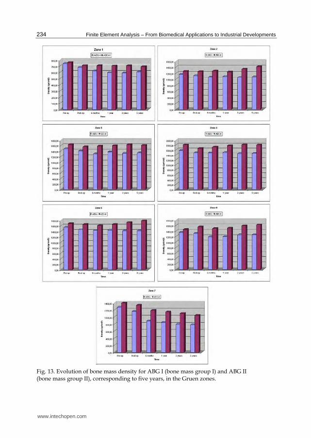
BMD evolution in the operated and healthy hip is shown in Fig. 13 for both prostheses. For ABG-I, the preoperative measurements performed in both hips showed slightly higher BMD rates in the healthy hip, although these were not statistically significant. Postoperative values were taken as a reference for the operated hip. A decrease in BMD was detected in all zones except zone 4, six months after surgery. Between 6 and 12 postoperative months there was a slight additional loss of BMD in zones 1 and 7, but some bone recovery in the middle and distal areas around the implant. No significant changes in BMD were observed in zones 1 to 6 from the end of the first year to the end of the fifth year.
For ABG-II, the preoperative measurements performed in both hips showed again slightly higher bone density rates in the healthy hip, although these were not statistically significant. No changes or a minimal decrease in bone density was detected in zones 1 to 6, six months after surgery, attributed to rest period, partial weight bearing and the later effects of surgery. The bone loss was statistically significant only in zone 7. A slight additional loss of bone density was observed in zone 7, as well as some bone recovery in the middle and distal areas around the implant. Minor changes in bone density were observed in zones 1 to 6 from the end of the first year to the end of the fifth year. The bone mass remains stable in this period, with a little bone recovery in zones 2 and 6. Nevertheless, there was some decrease in zone 7 in the period between the first and fifth year, when a loss of 23.88% can be reached. The bone density in the contra-lateral healthy hip (bone mass group II) showed some slight differences during the follow-up, with decreases between 1.4 and 2.7%, more evident in the proximal part of the femur, richer in cancellous bone. The values obtained for zones 3 to 5 were similar to those of the operated femurs; in zones 2 and 6 they were slightly superior; only zones 1 and 7 showed significant differences.
Fig. 14 shows the results of the average von Mises stress (MPa), corresponding to the combinations of geometry (ABG-I, ABG-II) and prosthesis material for group I of bone mass at five years, and Fig. 15 shows the equivalent results for group II of bone mass. It can be confirmed that the global behaviour of the prostheses is the same in both models; however, in the case of the ABG-II stem higher stress values are reached on both the cancellous and cortical bones, fundamentally in the proximal zones.
A tensional increase is noticeable in the whole area close to the lesser trochanter with the use of the ABG-II stem, as well as the tensional increase that the insertion of the ABG-II prosthesis involves with respect to the ABG-I. These differences can be observed in a more clear way in Figs. 14 and 15. In both figures it is clearly noticeable that the result corresponding to the two material for every stem are practically the same (superimposed lines); however, the results corresponding to both geometrical designs (ABG I, ABG II) are different, with a higher tensional level for the ABG II stem.
www.intechopen.com
Finite Element Analysis – From Biomedical Applications to Industrial Developments
234
Fig. 13. Evolution of bone mass density for ABG I (bone mass group I) and ABG II (bone mass group II), corresponding to five years, in the Gruen zones.
www.intechopen.com

Simulation by Finite Elements of Bone Remodelling After Implantation of Femoral Stems
235
It could be checked that in every case the stress corresponding to the ABG-II stem is greater than the one resulting from the insertion of the ABG-I stem (Figs. 14 and 15). In the figures it can be seen that in every zone and for any time the stress achieve higher values in ABG-II than in ABG-I stem. This way it is possible to confirm that with the second generation of stem (ABG-II) the stress increases in practically every zone with this increase being most evident in zone 7.
Fig. 14. Comparison of the average von Mises stress as a function of design and material for bone mass group I
www.intechopen.com

Finite Element Analysis – From Biomedical Applications to Industrial Developments
236
Fig. 15. Comparison of the average von Mises stress as a function of design and material for bone mass group II
Figure 16 shows the evolution of the bone mass (%) and the average von Mises stress (%) for each one of the 7 Gruen zones in both models, considering the corresponding group and material for each stem.
www.intechopen.com

Simulation by Finite Elements of Bone Remodelling After Implantation of Femoral Stems
237
Fig. 16. Bone mass (%) variation versus time and variation in average von Mises (%) stress versus time for the femur with prosthesis ABG-I and ABG-II in the Gruen zones
www.intechopen.com

Finite Element Analysis – From Biomedical Applications to Industrial Developments
238
4. Application to the behaviour of hip prostheses. Cemented stems
In the case of cemented stems the process of modelling was similar, varying the surgical cut in the femoral neck of the healthy femur. Each stem was positioned into the femur, always taking the superimposed mesh of the operated femur as a base (Fig. 17). In the previous process of modelling, on the cadaveric femur, only the cortical bone was used. The cancellous bone was modelled again taking into account the cement mantle surrounding the prosthesis and the model of stem (ABG or Versys), so as to obtain a perfect union between cement and cancellous bone. The cement mantle was given a similar thickness, in mm, which corresponds to that usually achieved in patients operated on, different for each of the stem models studied and each of the areas of the prosthesis, so that the model simulation be as accurate as possible. Cemented anatomical stem ABG, and the Versys straight, polished stem, were used in the study.
(a) (b)
Fig. 17. Removal of the femoral head and cemented prosthesis positioning: (a) ABG-cemented and (b) Versys
In the models of cemented prostheses it is not necessary to define contact conditions between the cancellous bone and the stem. In this type of prosthesis the junction between these two elements is achieved by cement, which in the EF model should simulate conditions of perfect union between cancellous bone-cement and cement-stem. It has also been necessary to model the diaphyseal plug that is placed in actual operations to prevent the spread of the cement down to femoral medullary canal. Fig. 18 shows the coronal sections of the final models.
www.intechopen.com

Simulation by Finite Elements of Bone Remodelling After Implantation of Femoral Stems
239
(a) (b)
Fig. 18. Longitudinal section of the FE models with cemented femoral prostheses: (a) ABG-cemented and (b) Versys.
(a) (b)
Fig. 19. FE model with cemented femoral prostheses: (a) ABG-cemented and (b) Versys.
www.intechopen.com

Finite Element Analysis – From Biomedical Applications to Industrial Developments
240
Both models were meshed with tetrahedral solid elements linear type, with a total of 74192 elements in the model for ABG-cemented prosthesis (33504 items cortical bone, cancellous bone 17859, 6111 for the ABG stem-cement, cement 13788 and 2930 for diaphyseal plug), and 274651 in the model for prosthetic Versys (119151 items of cortical bone, cancellous bone 84836, 22665 for the Versys stem, 44661 for the cement and 3338 in diaphyseal plug). In Fig. 19 are shown both models for cemented stems. Boundary conditions were imposed in the same way as in the cementless stems (Fig. 20).
Fig. 20. Boundary conditions
Calculation was performed using again the program Abaqus 6.7. Both prostheses have been simulated with the same mechanical properties, thus, the result shows the influence of stem geometry on the biomechanical behavior. Figs. 21 and 22 show the variation (%) of bone mass and average von Mises stress (%) in each of the Gruen zones for each of the models of cemented prostheses, with reference to the preoperative time. It can be seen that for both stems, the maximum decrease in bone mass occurred in Zone 7. This decrease in bone mass is greater in the Versys model than in the ABG stem
www.intechopen.com

Simulation by Finite Elements of Bone Remodelling After Implantation of Femoral Stems
241
Fig. 21. BMD and average von Mises stress evolution for ABG cemented stem
www.intechopen.com

Finite Element Analysis – From Biomedical Applications to Industrial Developments
242
Fig. 22. BMD and average von Mises stress evolution for Versys cemented stem
www.intechopen.com

Simulation by Finite Elements of Bone Remodelling After Implantation of Femoral Stems
243
5. Conclusion
Prior to the development of our FE models several long-term studies of bone remodeling after the implantation of two different cementless stems, ABG I and ABG II, were performed (Panisello et al., 2006; Panisello et al., 2009a; Panisello et al., 2009b). These studies were performed using DXA, a technique that allows an accurate assessment of bone density losses in the different Gruen zones. We take as a reference to explore this evolution the postoperative value obtained in control measurements and those obtained from contralateral healthy hip. New measurements were made at 6 months, one year and 5 years after surgery. The ABG II stem is an evolution of the ABG I, which has been modified both in its alloy and design. The second generation prosthesis ABG-II is manufactured with a different titanium alloy from that used in the ABG-I. The prosthetic ABG-I stem is made with a Wrought Titanium alloy (Ti 6Al-4V) of which elasticity modulus is 110 GPa. Meanwhile, the TMZF alloy, which is used on the ABG-II stem, has a Young’s modulus of 74-85 GPa, according to the manufacturer information, using a mean value of 79.5 GPa in the different analyses. On the other hand, the ABG II stem has a new design with less proximal and distal diameter, less length and the shoulder of stem has been redesign to improve osteointegration in the metaphyseal area.
In our DXA studies, directed to know the loss of bone mass in the different zones of Gruen caused by the stress-shielding, we found that ABG II model produces less proximal bone atrophy in post-operative measurements, for similar follow-up periods. In the model ABG II, we keep finding in studies with DXA a proximal bone atrophy, mainly in zones 1 and 7 of Gruen, but with an improvement of 8.7% in the values obtained in ABG I series. We can infer that improvements in the design of the stem, with a narrower diameter in the metaphyseal area, improve the load transfer to the femur and therefore minimizes the stress-shielding phenomenon, resulting in a lower proximal bone atrophy, because this area receive higher mechanical stimuli. These studies for determination of bone mass in Gruen zones, and the comparative study of their postoperative evolution during 5 years have allowed us to draw a number of conclusions: a) bone remodelling, after implantation of a femoral stem, is finished one year after surgery; b) variations in bone mass, after the first year, are not significant.
The importance of these studies is that objective data from a study with a series of patients allow us to confirm the existence of stress-shielding phenomenon, and quantify exactly the proximal bone atrophy that occurs. At the same time they have allowed us to confirm that the improvements in the ABG stem design, mean in practice better load transfer and less stres-shielding phenomenon when using the ABG II stem.
DXA studies have been basic to validate our FE models, because we have handled real values of patients' bone density, which allowed us to measure mechanical properties of real bone in different stages. Through computer simulation with our model, we have confirmed the decrease of mechanical stimulus in femoral metaphyseal areas, having a higher stimulus in ABG II type stem, which corresponds exactly with the data obtained in studies with DXA achieved in patients operated with both models stems.
In the case of cemented stems, densitometric studies were performed with two different types of stem: one straight (Versys, manufactured in a cobalt-chromium alloy) and other anatomical (ABG, manufactured in forged Vitallium patented by Stryker Howmedica). It
www.intechopen.com

Finite Element Analysis – From Biomedical Applications to Industrial Developments
244
Fig. 23. Stress distributions in coronal plane: a) minimum principal (compression); b) maximum principal (tension)
www.intechopen.com

Simulation by Finite Elements of Bone Remodelling After Implantation of Femoral Stems
245
was carried on the same methodology used in the cemented stems series. Densitometric studies previously made with cementless stems allow us to affirm that bone remodeling is done in the first postoperative year, a view shared by most of the authors. So, we accept that bone mineral density values obtained one year after surgery can be considered as definitive. As in cementless models, densitometric values have been used for comparison with those obtained in the FE simulation models. Our studies confirmed that the greatest loss of bone density affects the zone 7 of Gruen (Joven, 2007), which means that stress-shielding and atrophy of metaphyseal bone also occurs in cemented prostheses. This phenomenon is less severe than in non-cemented stems, therefore we can conclude that the load transfer is better with cemented stems than with cementless stems. The findings of proximal bone atrophy, mainly in the area 7, agree with those published by other authors (Arabmotlagh et al., 2006; Dan et al., 2006). We have also found differences in the rates of decrease in bone density in the area 7 of Gruen, wich were slightly lower in the anatomical ABG stem than in the Versys straight stem. This also indicates that the prosthesis design has influence in the remodeling process, and that mechanical stimuli are different and related to the design.
From a mechanical point of view, in the case of cementless stems, the improvements in the design are limited for the intrinsic behaviour of the mechanical system stem-bone. So if the compression and tension distributions are depicted (Fig. 23), one can see that, at initial steps without osteointegration, compression stresses can be transmitted in the contact interface but not tension stresses. Therefore the bending moment due to the load eccentricity only can be equilibrated by means of a couple of forces acting at points A and B, respectively, as shown in Fig. 23b. This behaviour explain the proximal bone atrophy in zone 7 of Gruen, and depending on the actual position of point A the same effect in zone 1 of Gruen. A similar effect occurs in cemented stems when the debonding appears at the bone-cement interface in the tensioned zones.
6. References
ABAQUS (2009). Web site, http://www.simulia.com/ Arabmotlagh, M.; Sabljic, R. & Rittmeister, M. (2006). Changes of the biochemical markers of
bone turnover and periprosthetic bone remodelling after cemented arthroplasty. J Arthroplasty, 21, 1, 129-34. ISSN: 0883-5403
Ashman, R. B., Cowin, S. C.; Van Buskirk, W. C. et al. (1984). A continuous wave technique for the measurement of the elastic properties of cortical bone. J Biomech, 17, 349–61. ISSN: 0021-9290
Ashman, R. B. & Rho, J. Y. (1988). Elastic modulus of trabecular bone material. J Biomech, 21, 177-81. ISSN: 0021-9290
Bathe, K. J. (1982). Finite element procedures in engineering analysis, Prentice-Hall, New Jersey. ISBN-10: 0133173054
Braun, A.; Papp, J. & Reiter, A. (2003). The periprosthetic bone remodelling process signs of vital bone reaction. Int Orthop, 27, S1, 7-10. ISSN: 0341-2695
Buckwalter, J. A.; Glimcher, M. J.; Cooper, R. R. et al. (1995). Bone biology, J Bone Joint Surg
Am, 77, 1276-1289. ISSN: 0021-9355 Bugbee, W.; Culpepper, W.; Engh, A. et al. (1997). Long-term clinical consequences of stress-
shielding after total hip arthroplasty without cement. J Bone Joint Surg Am, 79, 1007-12. ISSN: 0021-9355
www.intechopen.com

Finite Element Analysis – From Biomedical Applications to Industrial Developments
246
Canales, V.; Panisello, J. J.; Herrera, A. et al. (2006). Ten year follow-up of an anatomical hydroxyapatite-coated total hip prosthesis. Int Orthop, 30, 84-90. ISSN: 0341-2695
Charnley, J. (1961). Arthroplasty of the hip: a new operation. Lancet, 1129-32. ISSN: 0140-6736
D’Antonio, J. A.; Manley, M. T.; Capello, W. N. et al. (2005). Five year experience with Crossfire highly cross-linked polyethylene. Clin Orthop Relat R, 441, 143-50. ISSN: 0009-921X
Dan, D.; Germann, D.; Burki, H. et al. (2006). Bone loss alter total hip arthroplasty. Rheumatol
Int, 26, 9, 792-8. ISSN: 0172-8172 Engh, C. A. Jr.; Mc Auley, J.P.; Sychter, C.J. et al. (2000). The accuracy and reproducibility of
radiographic assessment of stress-shielding. J Bone Joint Surg Am, 82, 1414-20. ISSN: 0021-9355
Engh, C. A. Jr; Young, A. M.; Engh, C. A. Sr. et al. (2003). Clinical consequences of stress shielding after porous-coated total hip arthroplasty. Clin Orthop Relat R, 417, 157-63. ISSN: 0009-921X
Evans, F. G. (1973). The Mechanical Properties of Bone. American Lecture Series, n. 881, Springfield, IL. ISBN: 0398027757
Faris, P. M.; Ritter, M. A.; Pierce A. L. et al. (2006). Polyethylene sterilization and production affects wear in total hip arthroplasties. Clin Orthop Relat R, 453, 305-8. ISSN: 0009-921X
Gibbons, C. E. R.; Davies, A. J.; Amis, A. A. et al. (2001). Periprosthetic bone mineral density changes with femoral components of different design philosophy. In Orthop, 25, 89-92. ISSN: 0341-2695
Glassman, A. H.; Crowninshield, R. D.; Schenck, R. et al. (2001). A low stiffness composite biologically fixed prostheses. Clin Orthop Relat R,, 393, 128-136. ISSN: 0009-921X
Glassman, A. H.; Bobyn, J. D. & Tanzer, M. (2006). New femoral designs: do they influence stress-shielding? Clin Orthop Relat R, 453, 64-74. ISSN: 0009-921X
Gordon, A. C.; D’Lima, D. D. & Colwell, C. W. (2006). Highly cross-linked polyethylene in total hip arthroplasty. J Am Acad Orthop Surg, 14, 9, 511-23. ISSN: 1067-151X
Grant, P. & Nordsletten, L. (2004). Influence of porous coating level on proximal femoral remodelling. J Bone Joint Surg Am, 86-A, 12, 2636-41. ISSN: 0021-9355
Gruen, T. A.; McNeice, G. M. & Amstutz H. C. (1979). Modes of failure of cemented stem-type femoral components: a radiographic analysis of loosening. Clin Orthop Relat R, 141, 17-27. ISSN: 0009-921X
Halley, D. K. & Wroblewski, B. M. (1986). Long-term results of low-friction arthroplasty in patients 30 years of age or younger. Clin Orthop Relat R, 211, 43-50. ISSN: 0009-921X
Harris, W. H.; McCarthy, J. & O’Neill, D. A. (1982). Femoral component loosening using contemporary techniques of femoral cement fixation. J Bone Joint Surg Am, 64, 7, 1063-67. ISSN: 0021-9355
Hellman, E. J.; Capello, W. N. & Feinberg, J. R. (1999). Omnifit cementless total hip arthroplasty: A 10-years average follow up. Clin Orthop Relat R, 364, 164-174. ISSN: 0009-921X
www.intechopen.com

Simulation by Finite Elements of Bone Remodelling After Implantation of Femoral Stems
247
Hennessy, D. W.; Callaghan, J. J. & Liu, S. S. (2009). Second-generation extensively porous-coated THA stems at minimum 10-year followup. Clin Orthop Relat R, 467, 9, 2290-6. ISSN: 0009-921X
Herrera, A.; Domingo, J. J. & Panisello, J. J. (2001). Controversias en la artroplastia total de cadera. Elección del implante. In: Actualizaciones en Cirugía Ortopedica y
Traumatología II, 141-62, Edit. Masson, Barcelona. ISBN: 8445810944 Herrera, A.; Canales, V.; Anderson, J. et al. (2004). Seven to ten years follow up of an
anatomic hip protesis. Clin Orthop Relat R, 423, 129-37. ISSN: 0009-921X
Herrera, A. & Panisello, J. J. (2006). Fisiología del hueso y remodelado óseo. In: Biomecánica y
resistencia ósea, 27-42, Edit MMC, Madrid. ISBN: 8468977116 Herrera, A.; Panisello, J. J., Ibarz, E. et al (2007). Long-term study of bone remodelling after
femoral stem: A comparison between dexa and finite element simulation. J Biomech, 40, 16: 3615-25. ISSN: 0021-9290
Herrera, A.; Panisello, J. J.; Ibarz, E. et al. (2009). Comparison between DEXA and Finite Element studies in the long term bone remodelling o an anatomical femoral stem. J Biomech Eng, 31, 4, 1004-13. ISSN: 0148-0731
Hughes, T. J. R. (1987). The finite element method, Prentice-Hall, New Jersey. ISBN-10 013317025X
Huiskes, R.; Weinans, H. & Dalstra, M. (1989). Adaptative bone remodeling and biomechanical design considerations for noncemented total hip arthroplasty. Orthopedics, 12, 1255-1267. ISSN: 0147-7447
I-DEAS (2009). Web site, http://www.ugs.com/ Imbert, F. J. (1979). Analyse des structures par élément finis, Cepadues Edit, Toulouse. ISBN:
2854280512 Ionescu, I.; Conway, T.; Schonning, A. et al. (2003). Solid modeling and static finite element
analysis of the human tibia. Summer Bioengineering Conference, 889-90, Florida. Jacobs, C. R. (1994). Numerical simulation of bone adaptation to mechanical loading. Dissertation
for the degree of Doctor of Philosophy, Stanford University. Joven, E. (2007). Densitometry study of bone remodeling in cemented hip arthroplasty with stem
straight and anatomical. Doctoral Degree Disertation, University of Zaragoza. Kerner, J.; Huiskes, R. ; van Lenthe, G. H. et al. (1999). Correlation between pre-operative
periprosthetic BMD and post-operative bone loss in THA can be explained by strain-adaptative remodelling. J Biomech, 32, 695-703. ISSN: 0021-9290
Kroger, H.; Miettinen, H.; Arnala, I. et al. (1996). Evaluation of periprosthetic bone using dual energy X-ray absorptiometry: precision of the method and effect of operation on bone mineral density. J Bone Miner Res, 11, 1526-30. ISSN: 0884-0431
Li, M. G.; Rohrl, S. M.; Wood, D. J. et al. (2007). Periprosthetic Changes in Bone Mineral Density in 5 Stem Designs 5 Years After Cemented Total Hip Arthroplasty. No Relation to Stem Migration. J Arthroplasty, 22, 5, 698-91. ISSN: 0883-5403
Marklof, K. L.; Amstutz, H. C. & Hirschowitz, D. L. (1980). The effect of calcar contact on femoral component micromovement.A mechanical study. J Bone Joint Surg Am, 62, 1315-1323. ISSN: 0021-9355
Mat Web (Material Property Data) (2009). Web site, http://www.matweb.com/ McAuley, J., Sychterz, Ch. & Ench, C. A. (2000). Influence of porous coating level on
proximal femoral remodeling. Clin Orthop Relat R, 371, 146-153. ISSN: 0009-921X
www.intechopen.com

Finite Element Analysis – From Biomedical Applications to Industrial Developments
248
Medel, F. J.; Gómez-Barrena, E.; García-Álvarez, F. et al. (2004). Fractography evolution in accelerated aging of UHMWPE after gamma irradiation in air. Biomaterials, 25, 1, 9-21. ISSN: 0142-9612
Meunier, A.; Riot, O. ; Christel, P. et al. (1989). Inhomogeneities in anisotropic elastic constants of cortical bone. Ultrasonics Symposium, 1015-1018.
MIMICS. (2010). Web site, http://www.materialise.com/ Mohler, C. G.; Callaghan, J. J.; Collis, D. K. et al. (1995). Early loosening of the femoral
component at the cement-prosthesis interface after total hip replacement. J Bone
Joint Surg Am, 77, 9, 1315-22. ISSN: 0021-9355 Mulroy, R. D.; Harris, W. H. (1990). The effect of improved cementing techniques on
component loosening in total hip replacement. An 11 year radiographic review. J Bone Joint Surg Br, 72, 5, 757-60. ISSN: 0301-620X
Noble, P. C.; Collier, M. B.; Maltry, J. A. et al. (1998). Pressurization and centralization enhance the quality and reproductibility of cementless. Clin Orthop Relat R, 355, 77-89. ISSN: 0009-921X
Nourissat, C.; Adrey, J.; Berteaux, D. et al. (1995). The ABG Standar hip prosthesis: Five year results. In: Hydroxyapatite coated hip and knee arthroplasty, 227-38, Epinette JA, Geesink RGT, Eds. Edit Expansion Cientifique Francaise, Paris. ISBN: 2704614709
Olsson, S. S.; Jenberger, A. & Tryggo, D. (1981). Clinical and radiological long-term results after Charnley-Muller total hip replacement. A 5 to 10 year follow-up study with special reference to aseptic loosening. Acta Orthop Scand, 52, 5, 531-42. ISSN: 0001-6470
Oral, E.; Christensen, S. D.; Malhi, A. S. et al. (2005). Wear resistance and mechanical properties of highly cross-linked, ultrahigh-molecular weight polyethylene doped with vitamin E. J Arthroplasty, 21, 4, 580-91. ISSN: 0883-5403
Panisello, J. J.; Herrero, L.; Herrera, A. et al. (2006). Bone remodelling after total hip arthroplasty using an uncemented anatomic femoral stem: a three-year prospective study using bone densitometry. J Orthop Surg, 14, 122-25. ISSN: 1022-5536
Panisello, J. J.; Herrero, L.; Canales, V. et al. (2009a). Long-term remodelling in proximal femur around a hydroxyapatite-coated anatomic stem. Ten years densitometric follow-up. J Arthroplasty, 24, 1, 56-64. ISSN: 0883-5403
Panisello, J. J.; Canales, V.; Herrero, L. et al. (2009b). Changes in periprosthetic bone remodelling alter redesigning an anatomic cementless stem. Inter Orthop, 33, 2, 373-80. ISSN: 0341-2695
Radin, E. L. (1980). Bimechanics of the Human hip. Clin Orthop Relat R, 152, 28-34. ISSN: 0009-921X
Ramaniraka, N. A.; Rakotomanana, L. R. & Leyvraz, P. F. (2000). The fixation of the cemented femoral component .Effects of stem stiffness, cement thickness and roughness of the cement-bone surface . J Bone Joint Surg Br, 82, 297-303. ISSN: 0301-620X
Reading, A. D.; McCaskie, A. W.; Barnes, M. R. et al. (2000). A comparison of 2 modern femoral cementing techniques: analysis by cement-bone interface pressure measurement, computerized image analysis and static mechanical testing. J
Arthroplasty, 15, 4, 479-87. ISSN: 0883-5403
www.intechopen.com

Simulation by Finite Elements of Bone Remodelling After Implantation of Femoral Stems
249
Rosenthall, L.; Bobyn, J.D. & Tanzer, M. (1999). Bone densitometry: influence of prosthetic design and hydroxyapatite coating on regional adaptative bone remodelling. Int
Orthop, 23, 325-29. ISSN: 0341-2695
Rubash, H. E.; Sinha, R. K.; Shanbhag, A. S. et al. (1998). Pathogenesis of bone loss after total hip arthroplasty. Orthop Clin N Am, 29(2), 173-186. ISSN: 0030-5898.
Schmidt, R.; Nowak, T.; Mueller, L. et al. (2004). Osteodensitometry after total hip replacement with uncemented taper-design stem. Int Orthop, 28, 74-7. ISSN: 0341-2695
Shirazi-Adl, A., Dammak, M. & Paiement, G. (1993). Experimental determination of friction characteristics at the trabecular bone/porous-coated metal interface in cementless implants. J Bio Mat Res A, 27, 167-75. ISSN: 1549-3296
Sinha, R. K.; Dungy, D. S. & Yeon, H. B. (2004). Primary total hip arthroplasty with a proximally porous-coated femoral stem. J Bone Joint Surg Am 86, 6, 1254-61. ISSN: 0021-9355
Stauffer, R. N. (1982). Ten-year follow-up study of total hip replacement. J Bone Joint Surg
Am, 64, 7, 983-90. ISSN: 0021-9355 Sumner, D.R. & Galante, J. O. (1992). Determinants of stress shielding: design versus
materials versus interface. Clin Orthop Relat R, 274, 202-12. ISSN: 0009-921X Sychter, C. J. & Engh, C. A. (1992). The influence of clinical factor on periprosthetic bone
remodeling. Clin Orthop Relat R, 322, 285-92. ISSN: 0009-921X Tanzer, M.; Maloney, W. J.; Jasty, M. et al. (1992). The progression of femoral cortical
osteolysis in association with total hip arthroplasty without cement. J Bone Joint
Surg Am, 74, 404-10. ISSN: 0021-9355 Tonino, A. J.; Therin, M. & Doyle, C. (1999). Hydroxyapatite coated femoral stems:
Histology and histomorphometry around five components retrieved at post-mortem. J Bone Joint Surg Br, 81, 148-54. ISSN: 0301-620X
Turner, M. J.; Clough, R. W.; Martin, M. C. & Topp, L. J. (1956). Stiffness and deflection analysis of complex structures. J Aeronautical Sciences, 23, 9, 805-823. ISSN: 0095-9812
Turner, C. H.; Rho, J. ; Takano, Y. et al. (1999). The elastic properties of trabecular and cortical bone tissues are similar: results from two microscopic measurement techniques. J Biomech, 32, 437-41. ISSN: 0021-9290
Turner, A. W. L.; Gillies, R.M.; Sekel, R. et al. (2005). Computational bone remodelling simulations and comparisons with DEXA results. J Orthop Res, 23, 705-12. ISSN: 0736-0266
Urriés, I; Medel, F. J.; Ríos F. et al. (2004). Comparative cyclic stress-strain and fatigue resistance behaviour of electron-beam and gamma irradiated UHMWPE. J Biomed
Mater Res B, 70, 1, 152-60. ISSN: 1552-4973 van der Val, B. C. H.; Rahmy, A. ; Grimm, B. et al. (2006). Preoperative bone quality as a
factor in dual-energy X-ray absorptiometry analysis comparing bone remodelling between two implant types. Int Orthop, On line. ISSN: 0341-2695
Weinans, H.; Huiskes, R. & Grootenboer, H. J. (1994). Effects of fit and bonding characteristics of femoral stems on adaptative bone remodelling. J Biomech Eng, 116, 4, 393-400. ISSN: 0148-0731
www.intechopen.com

Finite Element Analysis – From Biomedical Applications to Industrial Developments
250
Wick, M. & Lester D.K. (2004). Radiological changes in second and third generation Zweymuller stems. J Bone Joint Sur Br, 86, 8, 1108-14. ISSN: 0301-620X
Wolf, C.; Maninger, J.; Lederer, K. et al. (2006). Stabilisation of crosslinked ultra-high molecular weight polyethylene (UHMWPE)-acetabular components with alpha-tocopherol. J Mater Sci Mater Med, 17, 12, 1323-31. ISSN: 0957-4530
Zienkiewicz, O. C. (1967). The finite element method in structural and continuum mechanics, Prentice-Hall, New Jersey. ASIN: B000HF38VG
Zienkiewicz, O. C. & Morgan, K. (1983). Finite element and approximation, John Wiley & Sons, New York. ISBN 10: 0471982407
www.intechopen.com

Finite Element Analysis - From Biomedical Applications toIndustrial DevelopmentsEdited by Dr. David Moratal
ISBN 978-953-51-0474-2Hard cover, 496 pagesPublisher InTechPublished online 30, March, 2012Published in print edition March, 2012
InTech EuropeUniversity Campus STeP Ri Slavka Krautzeka 83/A 51000 Rijeka, Croatia Phone: +385 (51) 770 447 Fax: +385 (51) 686 166www.intechopen.com
InTech ChinaUnit 405, Office Block, Hotel Equatorial Shanghai No.65, Yan An Road (West), Shanghai, 200040, China
Phone: +86-21-62489820 Fax: +86-21-62489821
Finite Element Analysis represents a numerical technique for finding approximate solutions to partialdifferential equations as well as integral equations, permitting the numerical analysis of complex structuresbased on their material properties. This book presents 20 different chapters in the application of FiniteElements, ranging from Biomedical Engineering to Manufacturing Industry and Industrial Developments. It hasbeen written at a level suitable for use in a graduate course on applications of finite element modelling andanalysis (mechanical, civil and biomedical engineering studies, for instance), without excluding its use byresearchers or professional engineers interested in the field, seeking to gain a deeper understandingconcerning Finite Element Analysis.
How to referenceIn order to correctly reference this scholarly work, feel free to copy and paste the following:
Luis Gracia, Elena Ibarz, José Cegoñino, Antonio Lobo-Escolar, Sergio Gabarre, Sergio Puértolas, EnriqueLópez, Jesús Mateo, Antonio Herrera (2012). Simulation by Finite Elements of Bone Remodelling AfterImplantation of Femoral Stems, Finite Element Analysis - From Biomedical Applications to IndustrialDevelopments, Dr. David Moratal (Ed.), ISBN: 978-953-51-0474-2, InTech, Available from:http://www.intechopen.com/books/finite-element-analysis-from-biomedical-applications-to-industrial-developments/simulation-by-finite-elements-of-bone-remodeling-after-implantation-of-femoral-stems