simulation modelling practicenetwork-simulator-ns-2.7690.n7.nabble.com/attachment/... ·...
TRANSCRIPT

Simulation Modelling Practice and Theory 72 (2017) 1–22
Contents lists available at ScienceDirect
Simulation Modelling Practice and Theory
journal homepage: www.elsevier.com/locate/simpat
Implementation and performance evaluation of a mobile IPv6
(MIPv6) simulation model for ns-3
Manoj Kumar Rana
a , ∗, Bhaskar Sardar b , Swarup Mandal c , Debashis Saha
d
a SMCC, Jadavpur University, Kolkata, India b Dept of IT, Jadavpur University, Kolkata, India c Practice Head, Wipro Limited, Kolkata, India d MIS Group, Indian Institute of Management (IIM), Calcutta, Kolkata, India
a r t i c l e i n f o
Article history:
Received 14 March 2016
Revised 29 August 2016
Accepted 10 December 2016
Keywords:
Network simulation
Validation
IP mobility management
Mobile IPv6
Handoff management
ns-3
Model development
a b s t r a c t
Mobile internet protocol version 6 (MIPv6) is the base standard from the Internet Engi-
neering Task Force (IETF) for Internet Protocol (IP) based mobility management in wireless
networks. The next generation mobility management schemes are mainly following the
protocol stack of MIPv6. However, till date the widely-used network simulator version 3
(ns-3) – which aims to replace the aging ns-2 and its associated old-featured simulators
– does not have even in its latest version an MIPv6 module that is fully compliant to the
IETF specification. To fill this gap, we present in this work a novel MIPv6 simulation model
which can be integrated into ns-3. We explain the complete design logic of the module,
and also perform evaluation of the same in ns-3. To validate our proposition, we com-
pare its handoff performance results with both numerical results, obtained analytically,
and published results, based on Linux test bed, CNI-MIPv6 test bed and Objective modular
network testbed (OMNET ++ ) simulation. To show the usefulness of our contribution, we
have exemplified how hierarchical MIPv6 (HMIPv6) can be implemented by extending the
basic MIPv6 module proposed by us.
© 2016 Elsevier B.V. All rights reserved.
1. Introduction
With the tremendous growth of 3rd and 4th generation mobile wireless networks globally, managing IP mobility is
becoming a serious concern for network managers [1,2] . Currently, the most stable solution for host-based IP mobility man-
agement is MIPv6, standardized by the IETF [3] a few years back. However, MIPv6 suffers from two well-known major
drawbacks viz. high signaling overhead and long handover latency ( ∼3.68 s [4] ). To address this issue, IETF Working Group
on Mobility for IP: Performance, Signaling, and Handoff Optimization has published two additional schemes, namely fast han-
dover for MIPv6 (F-MIPv6) [5] and hierarchical MIPv6 (HMIPv6) [6] . Although these two protocols introduced new signaling
messages and additional functionality to the existing network entities, they kept the MIPv6 protocol stack almost intact. So
MIPv6 till date remains the fundamental protocol in the realm of IP-based mobility management. Consequently, the study
of any mobile IP-based environment will warrant the implementation of the underlying MIPv6 protocol in the first place.
Hence, today’s network simulators must contain built-in MIPv6 module to gain attraction among the researchers and imple-
menters.
∗ Corresponding author.
E-mail addresses: [email protected] (M.K. Rana), [email protected] (B. Sardar), [email protected] (S. Mandal), [email protected] (D.
Saha).
http://dx.doi.org/10.1016/j.simpat.2016.12.005
1569-190X/© 2016 Elsevier B.V. All rights reserved.
2 M.K. Rana et al. / Simulation Modelling Practice and Theory 72 (2017) 1–22
Table 1
SIGCOMM, MOBIWAC, CCNC, WCNC GLOBECOM, ICC and INFOCOM papers
in different implementation type categories.
Year Testbed Simulation Analytical Combination Total
2005 2 4 4 1 11
2006 2 8 5 1 16
2007 6 12 7 3 28
2008 7 4 7 2 20
2009 4 14 11 3 32
2010 3 6 8 2 19
2011 1 5 2 2 10
2012 2 8 6 4 20
2013 3 6 2 1 12
2014 0 0 0 0 0
2015 0 2 1 0 3
Total 30 69 53 19 171
Table 2
SIGCOMM, MOBIWAC, CCNC, WCNC GLOBECOM, ICC and IN-
FOCOM papers in different simulator type categories.
Year NS OMNET ++ OPNET Others Total
2005 3 0 0 1 4
2006 5 0 2 1 8
2007 5 2 2 3 12
2008 3 0 0 1 4
2009 6 2 1 5 14
2010 4 1 1 0 6
2011 2 1 1 1 5
2012 2 2 3 1 8
2013 3 2 0 1 6
2014 0 0 0 0 0
2015 1 0 0 1 2
Total 34 10 10 15 69
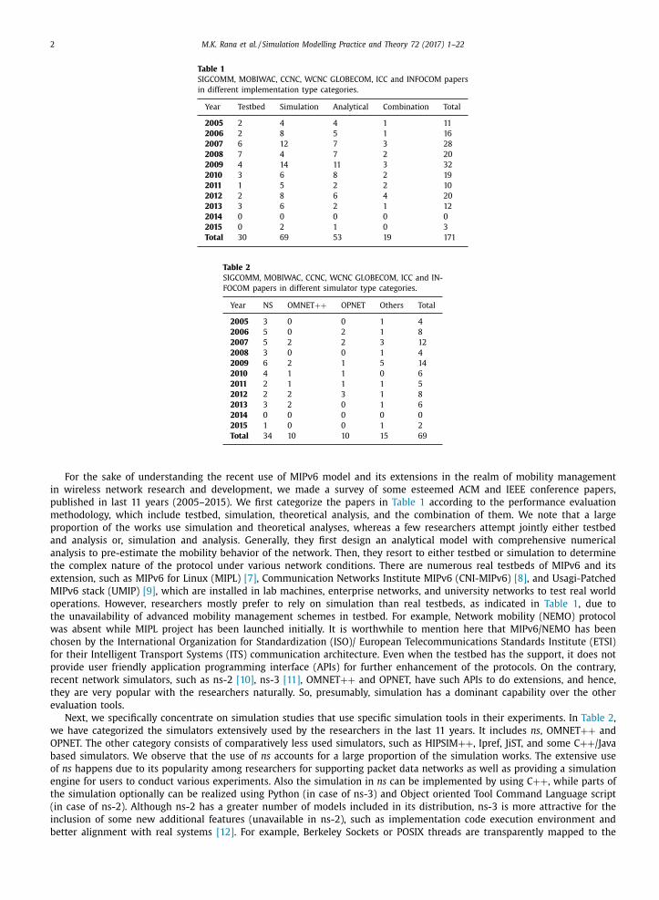
For the sake of understanding the recent use of MIPv6 model and its extensions in the realm of mobility management
in wireless network research and development, we made a survey of some esteemed ACM and IEEE conference papers,
published in last 11 years (2005–2015). We first categorize the papers in Table 1 according to the performance evaluation
methodology, which include testbed, simulation, theoretical analysis, and the combination of them. We note that a large
proportion of the works use simulation and theoretical analyses, whereas a few researchers attempt jointly either testbed
and analysis or, simulation and analysis. Generally, they first design an analytical model with comprehensive numerical
analysis to pre-estimate the mobility behavior of the network. Then, they resort to either testbed or simulation to determine
the complex nature of the protocol under various network conditions. There are numerous real testbeds of MIPv6 and its
extension, such as MIPv6 for Linux (MIPL) [7] , Communication Networks Institute MIPv6 (CNI-MIPv6) [8] , and Usagi-Patched
MIPv6 stack (UMIP) [9] , which are installed in lab machines, enterprise networks, and university networks to test real world
operations. However, researchers mostly prefer to rely on simulation than real testbeds, as indicated in Table 1 , due to
the unavailability of advanced mobility management schemes in testbed. For example, Network mobility (NEMO) protocol
was absent while MIPL project has been launched initially. It is worthwhile to mention here that MIPv6/NEMO has been
chosen by the International Organization for Standardization (ISO)/ European Telecommunications Standards Institute (ETSI)
for their Intelligent Transport Systems (ITS) communication architecture. Even when the testbed has the support, it does not
provide user friendly application programming interface (APIs) for further enhancement of the protocols. On the contrary,
recent network simulators, such as ns-2 [10] , ns-3 [11] , OMNET ++ and OPNET, have such APIs to do extensions, and hence,
they are very popular with the researchers naturally. So, presumably, simulation has a dominant capability over the other
evaluation tools.
Next, we specifically concentrate on simulation studies that use specific simulation tools in their experiments. In Table 2 ,
we have categorized the simulators extensively used by the researchers in the last 11 years. It includes ns , OMNET ++ and
OPNET. The other category consists of comparatively less used simulators, such as HIPSIM ++ , Ipref, JiST, and some C ++ /Java
based simulators. We observe that the use of ns accounts for a large proportion of the simulation works. The extensive use
of ns happens due to its popularity among researchers for supporting packet data networks as well as providing a simulation
engine for users to conduct various experiments. Also the simulation in ns can be implemented by using C ++ , while parts of
the simulation optionally can be realized using Python (in case of ns-3) and Object oriented Tool Command Language script
(in case of ns-2). Although ns-2 has a greater number of models included in its distribution, ns-3 is more attractive for the
inclusion of some new additional features (unavailable in ns-2), such as implementation code execution environment and
better alignment with real systems [12] . For example, Berkeley Sockets or POSIX threads are transparently mapped to the

M.K. Rana et al. / Simulation Modelling Practice and Theory 72 (2017) 1–22 3
simulation [11] in ns-3, which also demonstrates the best in overall performance in terms of scalability, low computational
overhead and less memory demands [12] .
Although, ns-3 has shown the potential to become the dominant network simulator gradually, the distribution of ns-3
till date is devoid of any core MIPv6 module. The only way out is the UMIP [13] support on Direct Code Execution (DCE)
framework, which enables the user to reuse the MIPv6 implementation of UMIP. But it is executable only on ns-3-dce
with Linux native stack [8] which, in turn, compels the users to touch the Linux protocol stack in case of any modification
proposed in MIPv6. For instance, an extension to any existing message format or an implementation of a new signaling
message or a modification of the functionality of a network entity necessitates corresponding change(s) in the protocol
stack of Linux system. Naturally, for a naive ns-3 user, it is quite cumbersome if she is unable to go to the depth of Linux
stack. This is preventing ns-3 from being used widely by the researchers/designers working in this domain.
To address the above problem, our work proposes an implementation, using ns-3 stack, of MIPv6 module in basic mode,
such that it can be easily added to ns-3. This will enable the common users, familiar with ns-3 alone, to easily modify or
extend the code in order to implement extended/advanced mobility management schemes 1 . For example, we have consid-
ered basic MIPv6 which implements hard handoff only. But one can extend this code to implement soft handoff as well.
Our implementation is guided by the following three approaches:
— Event driven triggering technique : an event requires triggering the corresponding function using ns-3 callback procedure
[11] . For example, MIPv6 binding update (BU) process starts just after the completion of the duplicate address detection
(DAD) mechanism of Internet Control Message Protocol for IPv6 (ICMPv6) [14] . For this, we have used a trigger in the
ICMPv6 protocol to invoke the binding process.
— Implementation of non-derived base classes : apart from using classes derived from ns-3 base classes, we have also de-
fined some new base classes, not provided in ns-3, and called them non-derived base classes . For instance, the binding
cache class (that stores handoff signaling information at home agent (HA)) is a non-derived base class, whereas the IPv6
mobility header class is derived from the ns-3 Header class.
— Helper class : it interconnects the low level APIs, used in the core MIPv6 module, to make the MIPv6 function installation
easier for naïve users. For example, the tedious and quiet long code for a mobile node (MN) can be installed on a network
entity by just using the install() method, defined in the MIPv6 MN helper class.
We have also presented extensive performance evaluation of the proposed module for validation purposes. The evaluation
part uses the tracing subsystem using tracehelper class. Tcpdump is used to see the pcap (packet capture) [15] files. We have
made about 100 test runs to measure the performance of our MIPv6 model. Finally, our proposed MIPv6 module is extended
to make a design framework of an IETF proposed protocol, hierarchical MIPv6 (HMIPv6). The existing MIPv6 features are
reused to develop this model quickly and easily. Further, extension of the base MIPv6 and HMIPv6 modules can assist
researchers to develop the fast handover schemes, such as F-MIPv6, fast HMIPv6 [16] , and optimized HMIPv6 [17] , which
are possibly better suited for the next generation networks.
The rest of the paper is organized as follows. In Section 2 , we discuss the related previous works on MIPv6 simula-
tion/emulation. A quick overview of MIPv6 and its handoff delay analysis are given in Section 3 for the sake of continuity in
reading. Section 4 begins with a brief discussion on the ns-3 components utilized by us to implement our MIPv6 module,
and then explains in detail the implementation of our proposed MIPv6 module. The simulation results to validate our im-
plementation are presented in Section 5 . Next, in Section 6 , we give a framework for simulating HMIPv6 in ns-3 using our
MIPv6 model with a view to showcasing the usability of our MIPv6 module. Finally, we conclude the paper in Section 7 .
2. Related works
Previously known simulations of MIPv6 may be broadly classified under four categories: (i) Linux based (e.g., CNI-MIPv6
Test Bed [8] ), (ii) OMNET ++ based (e.g., xMIPv6 [18,19] ), (iii) OPNET based (e.g., [20] ), and (iv) ns based (e.g., [21] ). We
discuss each of them briefly here.
2.1. Linux based implementations
Arguably the earliest implementation of MIPv6 in Linux was carried out in the Lancaster University in the UK [7] . How-
ever, since it supported only up to kernel 2.1.90, and was made compatible with IETF MIPv6 draft-v5 only (which is quite
older compared to the current revision), for all practical purposes we may consider it as obsolete now. Another similar im-
plementation, carried out under the Helsinki University of Technology’s MIPL project, is relatively better in the sense that it
supports kernel 2.4.22, and has patches for kernel 2.6 [22] . Still it is not up-to-date . CNI-MIPv6 [8] is a better-known Linux
based MIPv6 test bed established at the CNI, Dortmund University of Technology, with focuses on mobility management and
fast handovers in IPv6-based heterogeneous wireless access networks. However, its major limitation is the manual emula-
tion of MN movements. But its methodology to calculate the average delay by aggregating each of the delay components is
followed by other researchers too. We shall also do it in this paper while comparing our results with their results.
1 We are in the process of submitting our code to ns-3.

4 M.K. Rana et al. / Simulation Modelling Practice and Theory 72 (2017) 1–22
Other notable Linux implementations include – (a) USAGI Project of Japan, implementing IPv6 IPsec in MIPv6 stack [23] ,
(b) University of Southampton Project [24] , (c) UMIP (USAGI-patched Mobile IPv6) [9] , an open source MIPv6 released under
the GPLv2 license; it has patches for (NEMO) Basic Support [25] and F-MIPv6, and (d) Open Air Interface (OAI) Proxy MIPv6
(PMIPv6) implementation [26] by EURECOM [27] .
2.2. OMNET ++ based simulations
The most cited example under this category is extensible MIPv6 (xMIPv6) of Dortmund University of Technology [18,19] .
It is an INET20061020 based discrete event network simulator, which has its origin in an IPv6 framework [28] developed
in 2004. However, the beauty of xMIPv6 lies in its flexibility as it can be easily extended, with minimal modifications, to
other related modules, like IPv6 , keeping the base INET framework functionality unaffected. This group further enhanced
their OMNeT ++ based Mobility Management Simulation Engine for IPv6 networks to help users emulate other protocols,
such as MIPv6, F-MIPv6, and HMIPv6, and their possible combination on a single unified platform [29] . A similar effort is
conspicuously absent in the ns-3 domain, to the best of our knowledge, as per the published literature.
Nonetheless, the lack of support of MIPv6 for the OMNET ++ 3.2 platform necessitates a new collaborative project [30] to
enhance the INET20061020 framework, which will be an extension to the already existing IPv6 implementations of the INET
framework. It involves the two earlier players, namely Communication Networks Institute (CNI) and Dortmund University of
Technology, along with the Institute of Communications and Navigation, German Aerospace Centre (DLR) [30] . Though DLR
is focusing on the investigation of IP mobility protocols for aeronautical communication networks, they require a reliable
and accurate MIPv6 simulation model that would serve as a base below F-MIPv6 [5] , HMIPv6 [6] , NEMO [25] and PMIPv6
[26] . Recently, INET and xMIPv6 frameworks are extended in OMNET ++ 4.x version to support dynamic mobility anchor
point (MAP, described in Section 6 ) in HMIPv6 environment [31] .
Some more OMNET ++ based simulations of MIPv6 include [32–34] , albeit in different contexts. Later, the second imple-
mentation is extended to support HMIPv6 to evaluate the QoS-conditionalized BU procedure in both MIPv6 and HMIPv6.
2.3. OPNET based simulations
There are not many attempts under this category probably due to the fact that OPNET is not suitable for simulating
mobility management. In 2005, Le et. al. have presented an MIPv6 model of OPNET simulator for the test bed in the Institute
of Informatics of Goettingen University [20] . It includes the mobility configuration of the entities like MN, correspondent
node (CN) and HA. Then they have proposed an end-to-end tunneling extension [35] and a mobility aware transmission
control protocol extension [36] for MIPv6. This protocol solves the routing layer and transport layer problem of MIPv6. Later
the OPNET enterprise has launched HMIPv6 implementation model [37] , which is used sparingly now-a-days.
2.4. ns based simulations
The most common and popular network simulator being ns-2/3, definitely much attention is concentrated on this cat-
egory of works. Starting with numerous implementation of MIPv6 [38] , PMIPv6 [39] and HMIPv6 [40] in ns-2, now re-
searchers are experimenting with ns-3 for possible implementations of IPv6 and MIPv6 [13] . Our work falls under the latter
category.
Mauchle et al. [21] , as a part of their ongoing research work to implement PMIPv6, have given an MIPv6 implementation
framework consisting of three parts: (1) the support for mobility and tunnel set-up, (2) the tunneling framework, which
can implement a tunnel anywhere, using various protocols, and (3) the modification and extension of layer 2 (L2) related
protocols. Though their design framework shows us a way toward MIPv6 module implementation, it does not explore the
details of the core part.
The implementation details of PMIPv6 and its validation has been explored by Choi et al. [41] , who have given a nice
modular, class-based design framework for a mobility protocol simulation. We follow their design approach to some extent
only because PMIPv6 and MIPv6 have different functionality. First of all, being a network based approach, PMIPv6 operation
starts at an access router (AR) by a trigger, when a new MN attaches with an AR. On the contrary, MIPv6 is a host based
L3 triggered protocol. Second , PMIPv6 does not support route optimization. Third , a part of MIPv6 protocol stack with a
significant modification must be installed in CN. On contrary, PMIPv6 does not impose any modification on the CN.
3. Overview of MIPv6 and its handoff delay analysis
MIPv6 [3] is the basic host based mobility management protocol that guarantees session continuity to the MNs. The basic
system architecture for MIPv6 is shown in Fig. 1 . MIPv6 introduces a new principal functional entity named HA that typically
runs on a router. The main role of an HA is to create a binding cache entry for each currently registered and serving MNs.
On the other hand, the main role of an MN is to detect its movements and accordingly initiate mobility related signaling
with the HA and communicating entity such as CN. Subsequently, there are two possible communication modes between
the MN and the CN. First , bidirectional tunneling mode: The MN establishes a bidirectional tunnel with the HA. All packets
from the CN are routed to the HA, and the HA, in turn, tunnels the packets to the MN. Packets to the CN are first tunneled

M.K. Rana et al. / Simulation Modelling Practice and Theory 72 (2017) 1–22 5
AR1
MN
HA
CN
IP Tunnel
BU, BA with HA
Original IP Packet
HA Address MN CoA Original IP Packet
Encapsulated IP Packet
AR2RA
BU, BA with CN
Fig. 1. MIPv6 overview.
MN AR HA CN
2. RA
3. Neighbour Solicitation
Address Configured
Han
doff
Del
ay
4. BU
BA
5. Tunnel Setup6. Packet
7. RR Process
8. BU, BA
1. L2 Association
Fig. 2. MIPv6 handoff process.
(
(
from the MN to the HA and then routed normally to the CN. In the second mode, the MN performs route optimization with
the CN. All packets from the CN can now be routed directly to the MN bypassing the HA. The process of routing packets
directly to the MN utilizes the shortest communication path. The packets from the MN to the CN also follow some optimized
route.
3.1. Brief description of MIPv6
For the sake of continuity in reading, we show in Fig. 2 the signaling message flow of the whole handoff operation in
MIPv6. The steps are described as follows.
1) At first the MN associates with the AR’s wireless interface.
2) The MN receives router advertisement (RA) from the new AR and detects its movement using the prefix option included
in the RA message. Obviously, RA detection does not necessarily indicate a change in access network. A new RA implies

6 M.K. Rana et al. / Simulation Modelling Practice and Theory 72 (2017) 1–22
Table 3
Major MIPv6 components.
New Mobility Messages 1. BU type = 5 MN → HA, MN → CN
2. BA type = 6 HA → MN, CN → MN
3. Home Test Init (HoTI) type = 1 MN → HA → CN
4. Care-of Test Init (CoTI) type = 2 MN → CN
5. Home Test (HoT) type = 3 MN → HA → CN
6. Care-of Test (CoT) type = 4 MN → CN,
7. Binding Refresh Request type = 0 CN → MN,
8. Binding Error type = 7 CN → MN
Mobility Options 1. Pad1 type = 0 All
2. PadN type = 1 All
3. Binding Refresh Advice type = 2 BA (from HA)
4. Alternate CoA type = 3 BU (Both)
5. Nonce Indices type = 4 BU (to CN)
6. Binding Authorization Data type = 5 BU, BA (CN)
Data Structure 1. Binding Cache HA, CN
2. Binding Information List MN
Extension Header 1. Type2RoutingHeader CN → MN
Ipv6OptionHeader 1. Ipv6HomeAddressOptionHeader MN → CN
(
(
(
(
(
(
that source address and/or, advertised prefix and/or, RA parameters have changed. When an access network is changed
the afore-mentioned fields in the RA is changed at the same time. So, MIPv6 process starts, only if a new RA is received
by an MN with new advertised prefix.
3) Using the prefix option and its own Media access control (MAC) address, the MN configures a new care-of-address (CoA)
and performs DAD mechanism by multicasting neighbor solicitation message and waits to figure out if any other node is
using the same IP address. When DAD timeout occurs, the MN becomes sure that it may continue using the CoA.
4) The MN sends a BU to its HA and, in turn, receives a binding acknowledgement (BA) from the HA that confirms that the
BU is received and processed successfully.
5) Thus, a bidirectional tunnel is set up between the MN and the HA. The tunnel entry and exit point in the direction from
the HA to the MN are the HA address and MN’s CoA, respectively. In Fig. 1 , the original packet is encapsulated using
these two end points in the direction from the HA to the MN. In the opposite direction, the packet is encapsulated by
MN and the tunnel entry and exit points are MN’ CoA and HA address respectively.
6) Now, a packet can reach the MN from the CN via the HA using the tunnel.
7) The MN performs the return routability (RR) procedure with the CN. The RR procedure ensures the CN that the BU is
received from a correct MN.
8) Then, MN sends BU to the CN to send further packets in the optimized route.
Table 3 summarizes the new functional components of MIPv6, compared to IPv6. All new mobility messages use an
IPv6 extension header, called mobility header . The mobility header is identified by a “Next Header” value of 135 in the
immediately preceding header [3] . The mobility options are used in the “Mobility Option” field of the mobility messages.
Two new data structures, namely binding cache and BU list , are used to store the binding information with lifetime values.
The CN uses a Type2Routing header [3] to include MN’s Home Address (HoA), while sending packets directly to the MN.
Similarly, the MN uses a HoA Option header to include its HoA while sending packets directly to the CN. The HoA option
and Type2Routing header are also used for BU/BA messages between MN and HA. This allows the usage of IPSec to protect
the rest of the packets.
3.2. Handoff delay analysis
The handoff delay of MIPv6 can be defined as the time duration from L2 detachment of an MN from previous link to the
completion of BU process in the new link . So the handoff delay can be given as summation of movement detection delay ( t md ),
address configuration delay ( t ac ), and BU delay ( t bu ) [42,43] . Thus, the total handoff delay t handoff can be expressed as:
t handof f = t md + t ac + t bu (1)
The movement detection process starts after the detachment of MN from its previous link and finishes when it receives
first RA from the new link. Thus, t md consists of L2 handoff delay ( t l2 ) and RA delay ( t ra ). So, t md can be given as:
t md = t l2 + t ra (2)
In IEEE 802.11, the L2 handoff process involves three steps: probe request/reply, association request/reply, and authenti-
cation request/reply. When the MN switches access point (AP), it misses a bunch of beacons from the new AP and starts
probing introducing a delay of few milliseconds (say �). Let us denote by t β the one way message transfer delay in a
wireless link (link propagation delay and data transmission delay). Then t l2 can be found as follows:
t l2 = � + 2 t β + 2 t β = � + 4 t β (3)

M.K. Rana et al. / Simulation Modelling Practice and Theory 72 (2017) 1–22 7
HA
CN
AR1 AR2
MN MN
y
x x
echo request echo reply
echo reply echo request
echo request
echo reply
echo reply echo request
Fig. 3. Network scenario.
Table 4
Network parameters.
P d data packet size
P r Registration packet size
α wired link propagation delay
t β wireless link propagation and transmission delay
τ wired link data rate
λ traffic arrival rate
μ average service rate
x hop distance between AR and CN
y hop distance between CN and HA
The RA delay depends upon the RA intervals set by the AR and the timing of the MN to attach with the new link. As
given in [44] , t ra can be given as follows:
t ra =
R
2 max + R max R min + R
2 min
3 ( R max + R min ) (4)
In Eq. (4) , R max and R min are the MaxRtrAdvInterval and MinRtrAdvInterval , respectively. After receiving an RA message,
the MN configures a CoA and delays the DAD process randomly between zero and MAX_RTR_SOLICATION_DELAY . So, t ac is
given by [42] :
t ac = 0 . 5 ∗ MAX _ RT R _ SOLI CI T AT I ON _ DELAY + t DAD (5)
where t DAD is the DAD period. The BU process involves three phases: home registration, RR test, and correspondent registra-
tion. Let us denote the time required for these phases as t hr , t rr and t cr , respectively. Then t bu can be expressed as follows:
t bu = t hr + t rr + t cr (6)
To determine the round trip delay of the registration messages, we have assumed the network scenario, shown in Fig.
3 . In Table 4 , we have summarized network parameters which are required for our analysis. The round trip delay consists
of three delay components: link propagation delay, data transmission delay, and queuing delay at every intermediate node
[43] . To compute these delay components, we assume an echo request/reply application running between MN and CN. The
data transmission delay for registration message at each node is equal to P r / τ . Assuming M/M/1 queuing model [45] , the
queuing delay at each node would be 1/( μ- λ) . So, t hr , t rr and t cr can be calculated as follows:
t hr = 2 t β + 2(x + y ) α + 2
(P r
τ
)+
2 x
μ − λ(7)
t rr = 2 t β + 2(x + 2 y ) α + 2(x + 2 y ) P r
τ+
2(x + 1)
μ − λ+
2 y
μ − 2 λ(8)
t cr = 2 t β + 2(x + 2 y ) α + 2(x + 2 y ) P r
τ+
2(x + 1)
μ − λ+
2 y
μ − 2 λ(9)
8 M.K. Rana et al. / Simulation Modelling Practice and Theory 72 (2017) 1–22
helper protocols applications devices propagation ………
internet mobility network
core
Fig. 4. ns-3 model organisation.
It is to be noted that home registration occurs before the tunnel is set up between the HA and the MN via AR2 ( Fig. 3 ).
Hence, the home BU and BA packets face queuing delay only between the HA and the CN. So, in Eq. (7) , we do not consider
the queuing delay between the CN and the MN via AR2. On the other hand, the RR process includes round trip time for HoT
process only [3] . In HoT process, the home test init (HoTI) and its acknowledgement packet traverses the route between the
MN and CN via the HA. So the total hop distance for the HoT process is 2( x + 2 y ) which is accounted for computing total
transmission delay and link propagation delay in Eq. (8) . To compute queuing delay for HoT process, we note that two types
of traffic flows between the HA and the CN: (i) echo request packets generated by the CN are forwarded to the HA, and (ii)
echo reply packets generated by the MN are forwarded to the CN via the HA. So the traffic arrival rate between the CN and
the HA becomes 2 λ. Accordingly the queuing delay is computed in Eq. (8) . It is easy to observe that the above arguments
hold for Eq. (9) as well.
4. Implementation of MIPv6 module in ns-3
The ns-3 [11] is a discrete event network simulator which implements the simulation core and modules in C ++ . The
simulation core facilitates the ns-3 modules through the use of components, such as random numbers, attributes, default
values, and test frameworks. The ns-3 modules are abstract representation of real world objects, protocols, devices etc. It
is built as ns-3 library and may be statically or dynamically linked to C ++ main program, which defines the simulation
topology and starts the simulator.
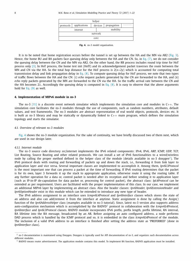
4.1. Overview of relevant ns-3 modules
Fig. 4 shows the ns-3 module organization. For the sake of continuity, we have briefly discussed two of them next, which
are used in our design later.
4.1.1. Internet module
The ns-3 source code directory src/internet implements the IPv6 related components: IPv4, IPv6, ARP, ICMP, UDP, TCP,
List Routing, Source Routing and other related protocols. We can install a set of IPv6 functionalities to a wired/wireless
node by calling the proper method defined in the helper class of the module (details available in ns-3 doxygen
2 ). The
IPv6 protocol deals with routing and forwarding of packets up and down the stack, i.e., forwarding it from link layer to
application layer and vice versa. Several important classes are implemented to accomplish it. Among them, Ipv6L3Protocol
is the most important one that can process a packet at the time of forwarding. If IPv6 routing determines that the packet
is for its own, layer 3 forwards it up the stack to appropriate application, otherwise route it using the routing table. If
any further operation for a data or, control packet is needed after its reception and before sending it to application layer
(such as IP-in-IP de-capsulation for data packet or, processing for control packet), the abstract class: IpL4Protocol can be
extended as per requirement. Users are facilitated with the proper implementation of this class. In our case, we implement
an additional MIPv6 layer by implementing an abstract class. Also the header classes: Ipv6Header, Ipv6ExtensionHeader and
Ipv6OptionHeader exist in this module which can be extended to introduce any new type of header.
The IPv6 address assignment to an interface uses Icmpv6L4Protocol and Ipv6Interface classes which stores the state of
an address and also can add/remove it from the interface at anytime. Static assignment is done by calling the Assign()
function of the Ipv6AddressHelper class (examples available in ns-3 tutorial). Since, latest ns-3 version also supports address
auto-configuration mechanism which is accomplished by the RADVD
3 protocol in collaboration with the Icmpv6L4Protocol,
Ipv6Interface and Ipv6L3Protocol classes. RADVD module incorporates IPv6 prefix, prefix length, prefix lifetime, RA interval,
RA lifetime into the RA message, broadcasted by an AR. Before assigning an auto configured address, a node performs
DAD process which is handled by the ICMP protocol and so, it is embedded in the class Icmpv6L4Protocol of the module.
The inclusion of a valid IPv6 address to an interface is finished after setting the address state as ‘PREFERRED’ (done in
Ipv6Interface class).
2 ns-3 documentation is maintained using Doxygen. Doxygen is typically used for API documentation of ns-3, and organizes such documentation across
different modules. 3 RADVD means router advertisement. The application module contains this model. To implement RA function, RADVD application must be installed.

M.K. Rana et al. / Simulation Modelling Practice and Theory 72 (2017) 1–22 9
Class Packetpublic functions
add/remove/peek headersadd/remove/peek tagsfragmentation & reassembly
private data membersBuffer objectPacketMetaData objectlist of byte tagslist of packet tags
Class Bufferpublic functions
Iterator to move byte buffer pointerfunction to read and write data of various size private data membersBufferData
Class Tagspublic functions
template to add, remove or, peek tagsfunction to read and write data of various size
private data memberssingly linked list of tagged data structure
Fig. 5. Members of packet class.
4.1.2. Network module
Among the Packet, Error model, Node, NetDevice, Socket, and Queue models of network module, Packet and NetDevice
frameworks are of our interest. The overview of these models is given in the following.
Packet. Each packet consists of: (i) a buffer object to store the serialized contents of the headers and trailers of the packet,
(ii) a set of byte tags to tag a subset of the bytes in the packet buffer, (iii) a set of packet tags to tag the packet itself, and
(iv) a packet metadata to describe the types of the headers and trailers, serialized in the buffer (Interested reader may find
the details about packet components in ns-3 doxygen). The main data members of the class are shown in Fig. 5 . The class
Header is the fundamental class for inserting to and deleting from the buffer. If we need to insert to or remove from packet
instance any protocol header, it is to be derived from the abstract Header base class and it should implement the following
virtual functions:
— Serialize()
— Deserialize()
— GetSerializedSize()
— Print()
The first three functions are used to serialize and deserialize protocol information to/from a Buffer. The last function is
used to define how the Header object prints itself onto an output stream.
Node and NetDevice. In ns-3, nodes are instances of ns3::Node class. The conceptual model is that one can aggregate or
insert objects to it. So, NetDevice and other protocols and applications can be added to it through aggregation. The NetDevice
interface defines the API which IP and ARP protocols use to manage an instance of a network layer device. If a user wants to
implement a new device, he/she needs to develop subclass of the NetDevice base class and implement his/her own version,
implementing the pure virtual methods of this class. A node can send a packet from L3 into network device after the IPv6
routing has decided that the packet received from the upper layer has to be sent through this particular device.
4.2. Implementation details of MIPv6 module
In this section, we walk through the implementation process of MIPv6 module in ns-3. The implementation process uses
the core features of ns-3, mainly the object aggregation model, the attribute system, the callback mechanism, the event
scheduling process, and the ns-3 support for implementing a new module (included in ns-3 manual) [11] . We have started
with the ns-3 support by running the ‘create-module.py’ command, moving onto ‘/src’ directory. It creates MIPv6 directory
which contains sub-directories like ‘/model’, ‘/helper’ and so on. The main C ++ source files and header files of the MIPv6
module have to be placed inside the ‘/model’ and ‘/helper’ directories and further specified in the ‘wscript’ file for execution.
These set of source files use other ns-3 features like the attribute system, the callback mechanism etc. In the following, we
have briefly discussed the implementation of MIPv6. A more detail discussion can be found in [46] . In this Section, we have
mainly discussed the internal functionality of the classes. To illustrate the flow of their operations, the BU process and data
packet process are also depicted. It is to be noted that, our design approach avoids any dependency on IPv4.
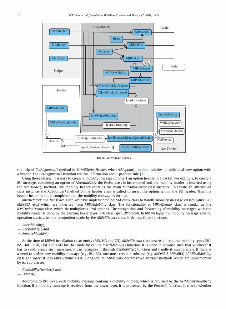
4.2.1. Main MIPv6 classes and their functional relationship
The major MIPv6 classes and the relationships among them i.e. inheritance, composition, and aggregation/association are
illustrated in Fig. 6 . The white boxes represent the classes which already exist in ns-3 and the classes with colored boxes
are newly defined to implement MIPv6. These classes are divided into four modules: header, internetstack, netdevice and
helper. In the following, important operations and the design techniques of the modules are discussed.
Header. In Fig. 7 , we have shown the main data members of MIPv6 header class (as defined in RFC 6275 [3] ) and the
relationship among them. As the type field of the options are used by the MIPv6 mobility messages, we cannot extend the
existing ns-3 Ipv6OptionHeader for the MIPv6 specific option headers. Mobility header (BU, BA, HoT etc.) class inherits the
MIPv6OptionField class too. It manages all the options available in the MIPv6 header and also performs the necessary padding
to ensure that the whole header remains a multiple of 8 octets. The padding mechanism uses CalculatePad() method with
10 M.K. Rana et al. / Simulation Modelling Practice and Theory 72 (2017) 1–22
Ipv6ListRouting
NetDevice
Node
MIPv6MN
MIPv6HA
MIPv6Demux
BCache
MIPv6CN
MIPv6Mobility
Ipv6SourceRouting
MIpv6MobL4Protocol
MIpv6TunL4Protocol
BList
TunNetDevice
MNHelper
HAHelper
CNHelper
MIPv6OptionHeader
MIPv6Header
Ipv6HomeAddressOptionHeader
Type2RoutingHeader
Header Ipv6OptionHeader
Ipv6ExtensionHeader
Helper
InternetStack Node
Net-Device
Header
CsmaNetDevice
WifiNetDevice
Ipv6L3Protocol
MIPv6Agent
Fig. 6. MIPv6 main classes.
the help of GetAlignment() method in MIPv6OptionHeader , when Addoption() method includes an additional new option with
a header. The GetAlignment() function returns information about padding rule [3] .
Using these classes, it is easy to create a mobility message or, insert an option header in a packet. For example, to create a
BU message, containing an option of AlternateCoA, the Packet class is instantiated and the mobility header is inserted using
the AddHeader() method. The mobility header contains the main MIPv6BUHeader class instance. To Create an AlternetCoA
class instance, the AddOption() method of the header class is called to insert the option within the BU header. Thus the
header instantiation is completed and the mobility message is formed.
InternetStack and NetDevice. First, we have implemented MIPv6Demux class to handle mobility message classes ( MIPv6BU,
MIPv6BA etc.) which are inherited from MIPv6Mobility class. The functionality of MIPv6Demux class is similar as the
IPv6OptionDemux class which de-multiplexes IPv6 options. The recognition and forwarding of mobility messages with the
mobility header is done by the existing lower layer IPv6 class ( Ipv6L3Protocol ). In MIPv6 layer, the mobility message specific
operation starts after the recognition made by the MIPv6Demux class. It defines three functions:
— InsertMobility()
— GetMobility() and
— RemoveMobility()
At the time of MIPv6 installation to an entity (MN, HA and CN), MIPv6Demux class inserts all required mobility types (BU,
BA, HoTI, CoTI, HoT and CoT) for that node by calling InsertMobility () function. It is done in advance such that whenever it
has to send/receive such messages, it can recognize it through GetMobility() function and handle it appropriately. If there is
a need to define new mobility message (e.g., BU, BA), one must create a subclass (e.g. MIPv6BU, MIPv6BA ) of MIPv6Mobility
class and insert it into MIPv6Demux class. Alongside, MIPv6Mobility declares two abstract methods which are implemented
by its sub classes:
— GetMobilityNumber() and
— Process()
According to RFC 6275, each mobility message contains a mobility number, which is returned by the GetMobilityNumber()
function. If a mobility message is received from the lower layer, it is processed by the Process() function. It checks whether

M.K. Rana et al. / Simulation Modelling Practice and Theory 72 (2017) 1–22 11
Header
+Print () +Serialize () +GetSerializedSize () +Deserialize ()
MIPv6OptionField
+Serialize () +Deserialize () +AddOption () +CalculatedPad ()
-m_optionData -m_optionOffset
Type2RoutingHeader -m_nextHeader -m_headerLength -m_routingType -m_segLeft -m_reserved -m_homeAddress
Ipv6ExtensionHeader -m_nextHeader
Ipv6OptionHeader -m_type -m_length
Ipv6HomeAddressOptionHeader -m_homeAddress
MIPv6Header -m_payloadProto -m_headerLen -m_mhType -m_reserved -m_checksum
MIPv6BUHeader -m_sequence -m_flagA -m_flagH -m_flagL -m_flagK -m lifetime
MIPv6BAHeader -m_status -m_flagK -m_reserved2 -m_sequence -m lifetime
MIPv6OptionHeader
+GetAlignment ()
-m_type -m_len
M_Pad1
M_PadN
BindingRefreshAdvice -m_refInterval
AlternateCoA -m coa
BindingAuthorizationData -m_authenticator
NonceIndices -m_homeNonceIndices -m_careofNonceIndices
1 *
HoTIHeader -m_reserved2 -m_hiCookie
HoTHeader -m_hnonceIndex -m_hiCookie -m_hkeytoken
CoTIHeader -m_reserved2 -m_coiCookie
CoTHeader -m_cononceIndex -m_coiCookie -m ckeytoken
Fig. 7. MIPv6 header class diagram.
all fields of the message is correct or, not. If it finds all the fields are meaningful to process further, it calls the appropriate
Receive() function of the node (i.e., MN, HA, and CN) to handle it. For example, the Receive() function of MIPv6HA is called
to send a BA message to the MN.
Secondly, we have placed the MIPv6 layer above IP layer by two main classes:
— MIPv6MobL4Protocol and
— MIPv6TunL4Protocol
The MIPv6MobL4Protocol class handles mobility messages and the MIPv6TunL4Protocol class deals with data packets.
Whenever a packet is received by Ipv6L3Protocol from lower layer, it forwards it to MIPv6 layer. The encapsulated data packet
12 M.K. Rana et al. / Simulation Modelling Practice and Theory 72 (2017) 1–22
or, a mobility message contains a type value (MH type) in its header which is different from normal data packet. Based on
this value, the appropriate L4 protocol class is associated. Both of them derived the Receive() function of the base IpL4Protocol
class. After receiving a mobility message in MIPv6MobL4Protocol , it calls the Process() function of the MIPv6Demux class to
process all the fields. Then, it calls the appropriate handler of that message defined in the entity class (e.g., MIPv6MN ).
On the other hand, the Receive() function of the MIPv6TunL4Protocol class checks an encapsulated packet’s tunnel interface
which has been used to de-capsulate the packet. If there is no matching tunnel interface in its binding cache/list, it drops
the packet. MIPv6TunL4Protocol class can also add, remove and modify a tunnel to a node. A tunnel is created by a virtual
mac layer net device to a node using the TunNetDevice class, derived from the base NetDevice class. The TunNetDevice class
re-implements the Send() function of the base class. Receiving a packet from the upper layer, the Send() function performs
IPv6-in-IPv6 encapsulation by forming a new IPv6 header with new source and destination address. So, the instantiation of
the TunNetDevice class is the main functionality of the MIPv6TunL4Protocol class. All the tunnel related methods are triggered
at the time of sending/receiving BU/BA messages of the agent classes ( MIPv6MN/HA/CN ) as defined in RFC 6275.
Third, we have implemented a new Ipv6SourceRouting class, deriving the base Ipv6ListRouting class. It checks the source
address of a packet and returns the route. This class is used by MN (i.e., MIPv6MN class). When a packet with MN’s HoA as
source address is generated, the routing protocol selects the virtual tunnel net device interface to tunnel the packet to the
HA. So, the MN keeps a route entry for its HoA in the routing table while the tunnel set up process is going on.
After the implementation of the above header classes, MIPv6 layer specific classes and routing classes, we implement the
agent based classes:
— MIPv6MN and
— MIPv6HA/CN
All of them are derived from the base MIPv6Agent class, which implements two main methods:
— Receive() and
— HandleXX()
The Receive() function is called by the Process() function of MIPv6Mobility class, after receiving a message from the
MIPv6MobL4Protocol class. After receiving such mobility message, it calls the proper handler function such as HandleBU(),
HandleBA() etc. These handler functions actually handle the mobility messages and trigger the next event. For example,
after receiving BU message, HandleBU() forms a BA message and sends it. However MIPv6Agent class has not defined the
handler classes as its function is specific to the agent classes. MIPv6MN and MIPv6HA classes can also insert and delete tun-
nel functionalities by calling specific functions defined in MIPv6MobL4Protocol class. At the time of receiving BU at HA and
receiving BA at MN, an AddHostRouteTo() function is called to insert host route in the routing table. If MN detaches from its
current link, a RemoveRouteTo() function is also called that removes the host route from the routing table. How MIPv6MN
class sends BU after configuring IPv6 address and how MIPv6HA class receives BU and sends BA is discussed in the next sub
sections.
Lastly, two independent classes: BCache and BList are associated with the MIPv6HA/CN and MIPv6MN classes respectively
( Fig. 6 ). They contain data members: CoA, HoA, lifetime, HA address, tunnel interface index, sequence number, BU state, and
nonce indices as defined in [3] . To handle the information of multiple MNs and HAs, each entry in the BCache and BList
class is keyed by the HoA.
Helper. Helper is also a supporting implementation module as the Header module. It basically works above all the main
implemented classes. Three helper classes are created for three agent classes. Users who want to run MIPv6, uses the helper
classes to install the MIPv6 functionality to corresponding nodes. These classes implement an important function called
Install() . This method takes a node pointer or, a node container object and the required data member like HA address as
arguments and install over a node or, a set of node (in case of Nodecontainer object). It installs the MIPv6MobL4Protocol and
MIPv6TunL4Protocol following the CreateObject() and AggregateObject() functions, defined in the core part of ns-3. After that
it registers the corresponding mobility messages using MIPv6MobL4Protocol class.
4.2.2. BU process
The BU process starts after MN configures an IPv6 address in a new subnet. If the state reaches in “PREFERRED” state, the
address configuration is successfully completed. Fig. 8 shows the BU process of MIPv6 in ns-3. After the DAD timeout event,
it sets the state by calling the SetState() method of Ipv6Interface class. The MIPv6MN class has set a function prototype,
m_NewIpCallback at Ipv6Interface class at the time of initialization. It invokes the BU sending process at MIPv6MN after
address configuration. It passes the packet to the default WifiNetDevice . Once the Ipv6 packet arrives at the netdevice of the
HA, it is delivered to the Ipv6L3Protocol through ProtocolHandler in Node class. Then, Ipv6L3Protocol passes the packet to the
right transport handler, checking the Ipv6 next header field in the packet. So, the BU packet is received at the HA in the
MIPv6MobL4Protocol . It then demultiplexes the packet in the MIPv6BU , based on mobility header type in BU packet. MIPv6BU
passes the packet to the MIPv6HA which creates or updates the binding cache and sets up tunnel for this new source. A BA
is sent to the MN in the similar process. The MN now creates or updates the BU list and sets up the tunnel towards the HA.
Thus, the BU process is completed. The BU process with CN is similar, but the tunnel setup and routing setup at MN and
CN do not occur.

M.K. Rana et al. / Simulation Modelling Practice and Theory 72 (2017) 1–22 13
Icmpv6L4Protocol
Ipv6Interface
MIPv6MN
Ipv6L3Protocol
WifiNetDevice NetDevice
Node::ProtocolHandler
Ipv6L3Protocol
IPv6MobL4Protocol
MIPv6BU
MIPv6HA
Ipv6L3Protocol
NetDevice
WifiNetDevice
Node::ProtocolHandler
Ipv6L3Protocol
IPv6MobL4Protocol
MIPv6BA
MIPv6MN
SetState( )
m_NewIpCallback
Send( )
Send( )
BU Received by HA
m_ReceiveCallback
Receive( )
Receive( )
Process( )
BUHandle( )
Send( )
Send( )
BA Received by MN
m_ReceiveCallback
Receive( )
Receive( )
Process( )
BAHandle( )
MIPv6Demux
GetType( )
MIPv6Demux
GetType( )
Disconnection Message sent to CN, MN
Fig. 8. BU process.
4.2.3. Data packet processing
At the completion of BU process, a bidirectional tunnel is set up between the HA and the MN. In Fig. 9 , the data packet
processing through the tunnel in the direction for MN to the HA is shown. Fig. 10 shows the data packet processing path in
the direction from the HA to the MN.
When a data packet arrives from application layer, Ipv6L3Protocol performs routing query for incoming packet by calling
RouteInput() method of Ipv6ListRouting class. Ipv6SourceRouting is used to find the route using MN’s HoA. It gives the out-
going tunnel netdevice interface as output to forward the packet. In TunNetDevice , the packet is encapsulated with another
Ipv6 header and is passed to Ipv6L3Protocol which sends the packet through the WifiNetDevice .
At the HA, encapsulated data packet is forwarded to the MIPv6TunL4Protocol following the Ipv6L3Protocol . The routing
query calls the LocalDeliver() function as the tunnel end point is at the HA’s global address. The Receive() function of the
MIPv6TunL4Protocol de-capsulates the packet and sends to Ipv6L3Protocol to send it to the CN.

14 M.K. Rana et al. / Simulation Modelling Practice and Theory 72 (2017) 1–22
Ipv6L3Protocol
TunNetDevice
Ipv6L3Protocol
WifiNetDevice NetDevice
Node::ProtocolHandler
Ipv6L3Protocol
m_ReceiveCallback
Receive( )
Ipv6TunL4Protocol
Ipv6L3Protocol
NetDevice
Ipv6ListRouting
Ipv6SourceRouting
RouteInput( ) IpForward( )
RouteInput( )
IpForward( )
Send( )
Send( )
Send( )
Receive( )
Send( )
Send( )
Send encapsulated packet to HA
Send Packet to CN Packet from application
Fig. 9. Data packet processing from the MN to the HA direction.
NetDevice
Ipv6L3Protocol
TunNetDevice
Ipv6L3Protocol
NetDevice WifiNetDevice
Node::ProtocolHandler
Ipv6L3Protocol
m_ReceiveCallback
Receive( )
Ipv6TunL4Protocol
Send( )
Send( )
Send( )
Receive( )
Send encapsulated packet to MN
Node::ProtocolHandler
Receive( )
m_ReceiveCallback
Send Packet to Upper Layer
Fig. 10. Data packet processing from the HA to the MN direction.

M.K. Rana et al. / Simulation Modelling Practice and Theory 72 (2017) 1–22 15
IP handoff
3001:db80::6/64 fe80::200:ff:fe00:6
3001:db80::5/64 fe80::200:ff:fe00:5
5001:db80::4/64 fe80::200:ff:fe00:4
2001:db80::2/64 fe80::200:ff:fe00:2
2001:db80::1/64 fe80::200:ff:fe00:1
5001:db80::3/64 fe80::200:ff:fe00:3
8888:56ac::7/64 fe80::200:ff:fe00:7
9999:db80::8/64 fe80::200:ff:fe00:8
9999:db80::200:ff:fe00:9 fe80::200:ff:fe00:9
8888:56ac::200:ff:fe00:9 fe80::200:ff:fe00:9
HA
AR1 AR2
MN
CN
Home Network Prefix 1001:db80::/64
5 m/sec
Fig. 11. Simulation topology.
On the other hand, packets from the CN are received by the HA and passed to Ipv6L3Protocol . Following Ipv6StaticRouting ,
the IpForward() method sends the packet to TunNetDevice as the routing table already contains a route entry for the MN’s
HoA. After encapsulation, Ipv6L3Protocol sends the packet to the MN. The MN processes the packet similarly as the HA.
Instead of sending the packet again to Ipv6L3Protocol , the MIPv6TunL4Protocol forwards it to the upper layer. Thus, The IP
mobility remains transparent to the upper layer. The trigger to start BU process with the CN starts after the reception of
BA message from the HA. The BU process is initiated by exchanging HoTI, CoTI, HoT, CoT messages used by MIPv6MN and
MIPv6CN class.
In case of route optimization, the CN uses the MN’s CoA as destination address. The event is triggered at Ipv6L3Protocol
class that sends data packet. For this, we have used a function prototype, m_NewRouteCallback at Ipv6L3Protocol class. It
changes the destination address to MN’s CoA. The value of this variable becomes true while the CN gets BU from MN and
successfully accepts it. Hence, all further packets would use the changed destination address. The value of the variable
becomes false when the CN gets a disconnection message from the HA. The HA sends this message to the CN immediately
after sending BA to the MN.
5. Simulation of MIPv6 and validation testing
We have performed extensive ns-3 simulations to analyze MIPv6 performance, thereby validating our implementation.
The simulation uses ns-3 version 3.19 with the IEEE 802.11 network [47] environment.
5.1. Simulation setup
The network topology of our simulation model is shown in Fig. 11 . The MN acts as a host, where the CN acts as both
host and router. All other nodes, including the HA, act as router only. The CN connects with AR1 and AR2 through carrier
sensing multiple access (CSMA) interface, and the HA connects with the CN using a point-to-point interface. The MN has
only one Wi-Fi interface with active probing off and connects with AR1 and AR2 through that interface. Both AR1 and AR2
are equipped with IEEE 802.11 radio data link, generating beacon every 100 ms. AR1 and AR2 advertise IPv6 prefix in the
16 M.K. Rana et al. / Simulation Modelling Practice and Theory 72 (2017) 1–22
Table 5
Simulation parameter values.
Parameter � α t β λ t DAD MAX_RTR_SOLICITATION_DELAY
Values 6.6 ms 1 ms 0.09 ms 100 /s 10 0 0 ms 10 0 0 ms
Parameter τ x y P m P d
Values 2 Mbps 1 1 34 bytes 1024 bytes
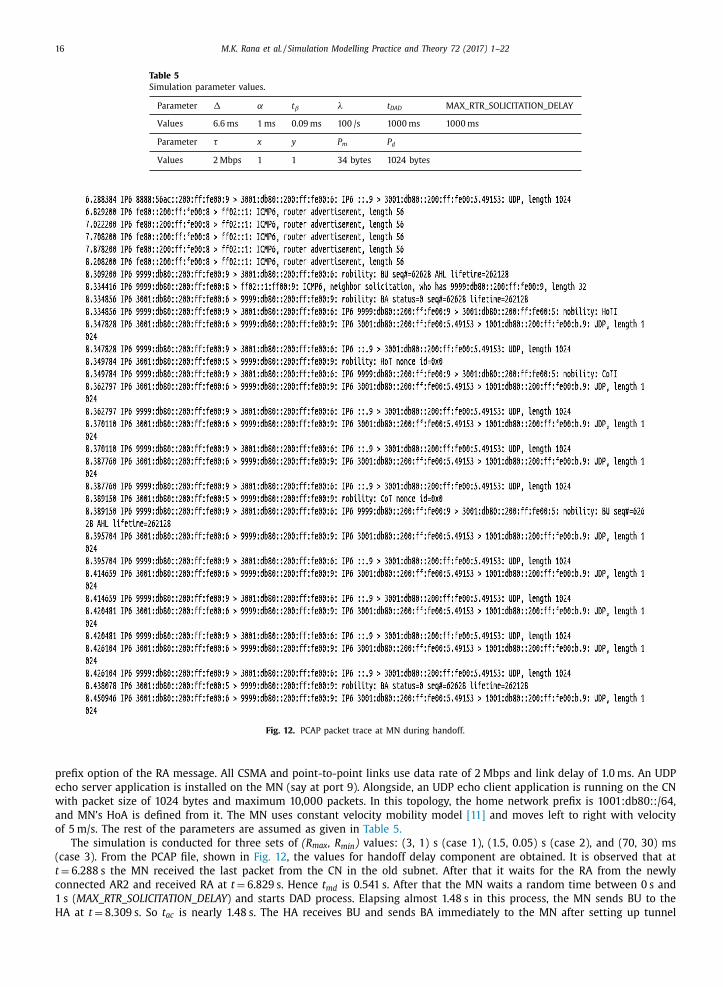
Fig. 12. PCAP packet trace at MN during handoff.
prefix option of the RA message. All CSMA and point-to-point links use data rate of 2 Mbps and link delay of 1.0 ms. An UDP
echo server application is installed on the MN (say at port 9). Alongside, an UDP echo client application is running on the CN
with packet size of 1024 bytes and maximum 10,0 0 0 packets. In this topology, the home network prefix is 1001:db80::/64,
and MN’s HoA is defined from it. The MN uses constant velocity mobility model [11] and moves left to right with velocity
of 5 m/s. The rest of the parameters are assumed as given in Table 5.
The simulation is conducted for three sets of (R max , R min ) values: (3, 1) s (case 1), (1.5, 0.05) s (case 2), and (70, 30) ms
(case 3). From the PCAP file, shown in Fig. 12 , the values for handoff delay component are obtained. It is observed that at
t = 6.288 s the MN received the last packet from the CN in the old subnet. After that it waits for the RA from the newly
connected AR2 and received RA at t = 6.829 s. Hence t md is 0.541 s. After that the MN waits a random time between 0 s and
1 s ( MAX_RTR_SOLICITATION_DELAY ) and starts DAD process. Elapsing almost 1.48 s in this process, the MN sends BU to the
HA at t = 8.309 s. So t ac is nearly 1.48 s. The HA receives BU and sends BA immediately to the MN after setting up tunnel

M.K. Rana et al. / Simulation Modelling Practice and Theory 72 (2017) 1–22 17
Table 6
Simulation results for handoff delay (in seconds).
Case#: (R max , R min ) Evaluation method t md t ac t hr t rr t cr t handoff
Case 1 (3 s,1 s) Analysis 1.090 1.500 0.019 0.080 0.080 2.769
Simulation 1.100 1.472 0.022 0.067 0.067 2.728
CI 15% 27% 99% 98% 97% 11%
Variation + 0.917% −1.867% + 15.789% −16.250% −16.250% + 1.481%
Case 2 (1.5 s, 0.05 s) Analysis 0.507 1.500 0.019 0.080 0.080 2.186
Simulation 0.583 1.487 0.022 0.067 0.067 2.226
CI 17% 25% 97% 98% 98% 14%
Variation + 14.990% −0.867% + 15.789% −16.250% −16.250% + 1.830%
Case 3 (70 ms, 30 ms) Analysis 0.033 1.500 0.019 0.080 0.080 1.712
Simulation 0.039 1.491 0.022 0.067 0.067 1.686
CI 20% 26% 99% 98% 99% 19%
Variation + 18.181% −0.600% + 15.789% −16.250% −16.250% −1.519%
Table 7
Simulation results for handoff delay (in milliseconds).
Case: Components Linux Test bed Our Simulator CI Variation
Case 1 t md 398 583 17% + 46.482%
t ac 1498 1487 25% −0.734%
t handoff 1896 2070 14% + 9.177%
Case 2 t md 936 1100 17% + 17.521%
t ac 1533 1472 27% −3.979%
t handoff 2469 2572 11% + 4.172%
and routing. The MN received BA at t = 8.335 s and sets up the tunnel and routing. So t hr is 0.026 s. Similarly, t rr and t cr
are obtained from Fig. 12 as 0.054 s and 0.049 s respectively. Then, ultimately the MN starts receiving encapsulated packets
from 8.451 s in the new subnet. From these obtained values, t bu is calculated as 2.163 s.
5.2. Validation with numerical results
To justify the correctness of our proposed simulation model, we have performed two sets of validation. First, we compare
the numerical results with our simulation results. Secondly, we compare our simulation results with Linux testbed results,
CNI MIPv6 testbed results and OMNET ++ based xMIPv6 simulation results, as reported in the literature. The validation
process is discussed in the following.
We show the comparison between the simulation results and the numerical results (obtained in Section 3.2 ) in Table 6 ,
where we depict the confidence interval 4 (CI) of our results and also the variation between the simulation result and the
analytical result. We observe that the handoff delay obtained from simulation is very close to the value obtained analytically.
This validates our simulation model undoubtedly. In the simulation, we have assumed that the L2 delay is the time duration
between the reception of last packet by MN from AR1 and the reception of RA from AR2. In numerical analysis, however, we
have ignored the time interval between the last packet reception at AR1 and the detachment from AR1 as negligible. For this
reason, the values of t md in simulation are slightly higher than its numerically obtained results in case 1. In cases 2 and 3, the
other delay component of t md , namely the RA delay, decreases but L2 delay remains fixed. So, we observe higher variation
of t md for cases 2 and 3 ( Table 6 ). A very small variation of t ac is observed, and it happens due to the random nature of
MAX_RTR_SOLICITATION_DELAY . We also note that the queuing delay during RR and correspondent registration is little low
in the simulation compared to the numerical results. It is due to the fact that we assumed higher packet transmission rate
for the numerical analysis than the simulation that decreases t rr and t cr values a little in the simulation.
The CI gained for t md and t ac are low because the RA interval and MAX_RTR_SOLICITATION_DELAY have random nature.
On the other hand, the CI for t hr , t rr , and t cr components is very high as there is no randomness to determine these delay
components. Hence we almost get the same values in each run of our simulation. We have observed that the CI for t handoff
is influenced by the randomness of t md and t ac .
5.3. Validation against experimental results
Linux Testbed. In [43] , Lee et al. conducted simulations for MIPv6 using Linux based MIPL 1.0 [8] . They considered only
t md and t ac components of handoff delay in their simulations. In Table 7 , we have compared our simulation results with
their results for two cases, defining R max –R min values: 1.5–0.05 s (case 1), and 3.0–1.0 s (case 2). The results are not too
different except the t value. This can be explained in terms of the seed value used to generate the random value of
md4 CI of a simulation parameter value ‘ v ’ is x% means x runs (out of total 100 runs) have produced ‘ v ’ as result.

18 M.K. Rana et al. / Simulation Modelling Practice and Theory 72 (2017) 1–22
Fig. 13. Handoff delay and events in terms of udp echo packets.
Table 8
Simulation results for handoff delay (in milliseconds).
Handoff Latency in Seconds Delay Components
T md t hr /T hr t rr /T rr t cr /T cr t ho /T HO
Test 1 CNI-MIPv6 3.288 1.040 0.005 0.003 4.336
xMIPv6 2.643 1.003 0.009 0.004 3.659
Our Simulator 2.600 1.022 0.009 0.004 3.635
CI 15% 98% 100% 99% 10%
Variation (from CNI-MIPv6) −20.924% −1.731% + 80% + 33.333% −16.259%
Variation (from xMIPv6) −1.627% + 1.894% 0% 0% −0.765%
Test 2 CNI-MIPv6 2.041 1.040 0.005 0.002 3.088
xMIPv6 2.131 1.003 0.009 0.004 3.147
Our Simulator 2.083 1.022 0.009 0.004 3.118
CI 17% 99% 98% 98% 12%
Variation (from CNI-MIPv6) + 2.058% −1.731% + 80% + 100% + 0.842%
Variation (from xMIPv6) −2.352% + 1.894% 0% 0% −1.049%
Test 3 CNI-MIPv6 1.558 1.041 0.005 0.002 2.606
xMIPv6 1.680 1.003 0.009 0.004 2.696
Our Simulator 1.539 1.022 0.009 0.004 2.574
CI 20% 100% 100% 99% 16%
Variation (from CNI-MIPv6) −1.219% −1.825% + 80% + 100% −1.381%
Variation (from xMIPv6) −8.393% + 1.894% 0% 0% −4.673%
MAX_RTR_SOLICITATION_DELAY and also the number of experiments carried out in the test bed (30 experimental runs) com-
pared to number of simulation runs (100 runs). Obviously, the seed in Linux based MIPL 1.0 generates lower values in small
number of runs compared to ns-3. Hence the difference is pronounced in Table 7 . The reason for low CI to determine t md ,
t ac , and t handoff is as discussed in Section 5.2 .
CNI-MIPv6 Testbed and xMIPv6 Simulation Model. In [19] , Yousaf et al., measured the MIPv6 handoff delay in both the
CNI-MIPv6 test bed and xMIPv6 simulation model. The parameters they used and defined slightly differs from our defini-
tions. To compute handoff delay they used movement detection delay ( T md ), home binding delay ( T hr ), RR delay ( T rr ) and
correspondent binding delay ( T cr ). Hence the overall delay ( T ho ) and T md can be expressed as follows:
T ho = T md + T hr + T rr + T cr (10)
T md = T l2 + T sd + T DAD (11)
In Eq. (11) , T l2 , T sd and T DAD are L2 handoff delay, subnet detection delay and DAD period respectively. We have used the
same simulation setup and same reference RA intervals as specified in [19] : 3.0–1.0 s (test 1), 1.5–0.05 s (test 2) and 0.03–
0.07 s (test 3) in our simulations. Fig. 13 illustrates the measured handoff delay (3.0 0 0 s) along with the handoff events
for the case of R max = 1.5 and R min = 0.05. The comparison between the results ( Table 8 ) clearly shows that the delay com-
ponents are almost same with their results. We have observed a significant variation of T md in case of CNI-MIPv6 testbed
in test1. It happens because of the high value of R max and R and also WLAN network setup in test bed and WLAN AP
min
M.K. Rana et al. / Simulation Modelling Practice and Theory 72 (2017) 1–22 19
MAP
Ipv6L3Protocol
HMIPMN
MIPv6Demux
BCache
HMIPLBU
HMIPLBA
HMIPTunL4Protocol
HMIPBList
HMIPMNHelper
HMIPMAPHelper
Helper InternetStack
Header
Icmpv6L4Protocol
Icmpv6OptionInformation Icmpv6OptionHeader
Common
HMIPIcmpv6L4Protocol
HMIPRadvdPrefix
HMIPRadvdInterface
HMIPRadvd
RADVD
Fig. 14. HMIPv6 class diagram.
configuration in ns-3 are different. So depending on ns-3 Wireless fidelity (wifi) specification, our obtained value for T md dif-
fers from their results. T hr is 1.0 s more in simulation results than the numerical results because HA runs DAD process (that
takes 1.0 s) before acknowledging home BU. In comparing T rr and T cr , there is a high variation between testbed, OMNET ++based simulator and our simulator results. It is due to the queuing delay considered in Section 3.2 . However, during home
registration, the queuing delay is not seen in between AR and HA, and so, there is no such variation in T hr . The reason for
low CI while computing T md and T HO is same as discussed in Section 5.2 .
6. A framework for HMIPv6 implementation
HMIPv6 [6] is an advanced mobility management scheme for the next generation all-IP networks. It replaces the distant
HA binding of MIPv6 by a quick registration process with a local host called MAP. For global roaming, however, it still
relies on MIPv6 process to provide a seamless IP handoff. Within a HMIPv6 domain, MN senses MAP’s presence through
AR’s advertisement that contains MAP option, and subsequently performs local BU (LBU) process with the MAP. Hence,
MAP option and LBU are the new objects in this scheme, which are to be actually reflected in our ns-3 implementation, as
discussed below.
In this section, we illustrate the new HMIPv6 components and the possible class diagram of HMIPv6 model. From the
given framework, the implementation of HMIPv6 will be easy for a naïve ns-3 user. Following the same process, other
similar IP mobility management protocols can also be implemented in ns-3 with little effort.
6.1. Additional components for HMIPv6
To simulate HMIPv6, we incorporate a new LBU mobility message, having the same type as that of BU message and with
an additional field. We also use the ICMP, but with a new option: option with type 23 [6] . The rest of the components
remain the same as those discussed in Table 3 of Section 3 .
6.2. Class diagram
The class diagram given in Fig. 6 in Section 4.2 is extended for HMIPv6 implementation as follows. The new and existing
classes with their relations are illustrated in Fig. 14 . For the new option type, the Icmpv6OptionHeader class is inherited. It
includes Icmpv6OptionInformation class, specifying the fields of the options and the corresponding operations. The option

20 M.K. Rana et al. / Simulation Modelling Practice and Theory 72 (2017) 1–22
Fig. 15. PCAP packet trace at MN using HMIPv6.
is included in the RA message by changing the RADVD application classes. In the RADVD sub module, the HMIPRadvdPrefix
class includes the option with the RA message as it includes other options. Consequently, the AddPrefix() and AddConfigu-
ration() functions of the RadvdInterface and Radvd classes are changed, and the classes are renamed as HMIPRadvdInterface
and HMIPRadvd classes, respectively.
HMIPv6MN acts quiet differently from MIPv6MN at the time of handling handoff signaling messages and processing the
data packet. It has to perform BU during its movement within the domain, which is different from HA binding process.
Also, doubly encapsulated packets are processed by the MN at the time of transmission/reception. Hence, MIPv6MN class is
changed into HMIPMN class to include the required functionalities. Similarly, MIPv6HA class is extended to HMIPHA class. To
store the new information such as address, distance and preference, the HMIPMN class has to constitute a new HMIPBList
class, instead of the existing BList class. To perform demultiplexing of the two additional BU messages (namely LBU and
LBA), the MIPv6Demux class is extended to accommodate HMIPLBU and HMIPLBA classes. The data packets are received and
processed accordingly in MIPv6TunL4Protocol class (Section 5.4). To process doubly encapsulated packets in HMIPv6, the
MIPv6TunL4Protocol class is changed to HMIPTunL4Protocol class.
6.3. Simulation
We have conducted simulation of our HMIPv6 model to test its handoff performance. From the IPv6 packet trace shown
in Fig. 15 , we have extracted the timing of the IPv6 packets at the time of inter-MAP handoff: the last packet through
the old AR and the first packet through the new AR are received at t = 24.617 s and t = 27.269 s, respectively. Hence, the
inter-MAP handoff delay is 2.652 s, which is almost equal to MIPv6 handoff delay obtained in [43] . In between these two
packet arrivals, MN performs in sequence RCoA request/reply, LBU with MAP and global BU (GBU) with the HA. The intra-
MAP handoff contains only LBU process after address configuration. Assuming that the same amount of time is involved
in movement detection and address configuration as shown in the packet trace file, the intra-MAP handoff delay can be
estimated as approximately 1.394 s, which tallies with the value reported in [48] . This vindicates the correctness of the
simulated HMIPv6 model, which, in turn, further validates our MIPv6 implementation in ns-3.
7. Conclusions
The network simulator ns-3 is yet to accommodate the MIPv6 module in its main tree. Unfortunately, this void is prevent-
ing the researchers from testing in ns-3 not only their novel mobility management techniques but also the next generation
protocols based on MIPv6. So, in this paper, we have proposed an MIPv6 simulation model for ns-3. Our results show the
consistent behavior of our simulation model in terms of the handoff delay. We have ensured the compliance of our model

M.K. Rana et al. / Simulation Modelling Practice and Theory 72 (2017) 1–22 21
by building the message/event timers and timeouts carefully in close conformance and strict adherence to the relevant IETF
standards.
Our proposed MIPv6 simulation model may be a useful groundwork for adding the new mobility management protocols
(like F-MIPv6, HMIPv6, F-HMIPv6 etc.) in ns-3 in near future. We have exhibited this potential through a simple simulation
of HMIPv6 using our MIPv6 model. The clear view of MIPv6 class inheritance, aggregation and operational modification of
existing MIPv6 model gives a very good understanding for the development of the new protocols. However, implementation
of dynamic HA address discovery, dual stack MIPv6 support, and HA multicasting membership control are missing in the
current implementation, and those are planned for our future work, which also includes experimenting the ns-3 develop-
ment in conjunction with simulation (emulation mode). This could be a way to test the conformity of the ns-3 simulation.
Acknowledgment
The authors would like to thank Dr. Tommaso Pecorella of University of Florence to fix the bug 2148 and push it in the
ns-3 change set.
References
[1] J.Jara Antonio, David Fernandez, Pablo Lopez, MiguelA. Zamora, AntonioF. Skarmeta, Lightweight mobile IPv6: a mobility protocol for enabling transpar-
ent IPv6 mobility in the Internet of Things, in: Proceedings of the IEEE Global Communications Conference (GLOBECOM, 2013), 2013, pp. 2791–2797,doi: 10.1109/GLOCOM.2013.6 8314 97 .
[2] Kuntz Romain, Julien Montavont, Thomas Noel, Multihoming in IPv6 mobile networks: progress, challenges, and solutions, Commun. Mag. IEEE 51 (1)(2013) 128–135, doi: 10.1109/MCOM.2013.6400449 .
[3] CharlesE. Perkins , DavidB. Johnson , Jari Arkko , Mobility support in IPv6, IETF, RFC, 6275, 2011 July . [4] Vasos Vassiliou , Zinon Zinonos , An analysis of the handover latency components in mobile IPv6, J. Internet Eng. 3 (2009) 230–240 .
[5] Rajeev Koodli , Fast handovers for mobile IPv6, IETF, RFC, 4068, 2008 June .
[6] Hesham Soliman , Claude Castelluccia , Karim ElMalki , Ludovic Bellier , Hierarchical mobile IPv6 (HMIPv6) mobility management, IETF, RFC, 5380, 2008October .
[7] Linux Mobile IPv6, Retrieved from http://www.cs-ipv6.lancs.ac.uk/MobileIP/ . [8] MIPL Mobile IPv6 for Linux, 2008. Retrieved from http://www.mobile-ipv6.org .
[9] Masafumi Aramoto, Masahide Nakamura, Shinta Sugimoto, Noriaki Takamiya. UMIP: USAGI-patched mobile IPv6 for Linux, 2008. Retrieved from http://umip.linux-ipv6.org/ .
[10] Lee Breslau, Deborah Estrin, Kevin Fall, Sally Floyd, John Heidemann, Ahmed Helmy, Polly Huang, Steven McCanne, Kannan Varadhan, Ya Xu, Haobo Yu,
Advances in network simulation, IEEE Comput. 33 (20 0 0) 5 59–67, doi: 10.1109/2.841785 . [11] Tom Henderson, George Riley, Sally Floyd, Sumit Roy. Network simulator 3, 2008. Retrieved from http://www.nsnam.org/ .
[12] Elias Weingartner, V.Lehn Hendrik, Klaus Wehrle, A performance comparison of recent network simulators, in: Proceedings of the IEEE InternationalConference on Communication (ICC 2009), 2009, doi: 10.1109/ICC.2009.5198657 .
[13] Hajime Tazaki, “Direct code execution”, 2013-2015, Retrieved from http://code.nsnam.org/ns- 3- dce and https://www.nsnam.org/docs/dce/manual-umip/html/index.html .
[14] Alex Conta , Stephen Deering , Mukesh Gupta , Internet control message protocol (ICMPv6) for the Internet Protocol Version 6 (IPv6) specification, IETF,RFC 4 4 43, March 2006 .
[15] The Tcpdump team. Library for packet capture version 4.7.4 April 2015. Retrieved from http://www.tcpdump.org/ .
[16] HeeY. Jung , Hesham Soliman , SeokJ. Koh , JaeYong Lee , Fast handover for hierarchical MIPv6 (F-HMIPv6), Internet Draft, IETF, 2005 , expires on April . [17] ManojK. Rana, Swarup Mandal, Bhaskar Sardar, Optimized HMIPv6 (O-HMIPv6): reducing handoff latency in HMIPv6 networks, in: Proceedings of
Application and Innovation in Mobile Communications (AiMoC 2015), 2015, pp. 18–24, doi: 10.1109/AIMOC.2015.7083824 . [18] Faqir Z. Yousaf, Christian Bauer, An accurate and extensible mobile IPv6 (xMIPV6) simulation model for OMNeT ++ , 2008. Retrieved from http://www.
kn.e- technik.tu- dortmund.de/en/forschung/ausstattung/xmipv6.html . [19] FaqirZ. Yousaf , Christian Bauer , Christian Wietfeld , An accurate and extensible mobile IPv6 (xMIPV6) simulation model for OMNeT ++ , in: Proceedings
of Simulation and Tools (Simutools ’08), ACM, 2008 Article No. 88. ISBN: 978-963-9799-20-2 .
[20] Deguang Le, Xiaoming Fu, Dieter Hogrefe, Evaluation of mobile IPv6 based on an OPNET model, in: Proceedings of 8th International Conference forYoung Computer Scientists (ICYCS’05), 2005 . doi: 10.1.1.474.7886 .
[21] Fabian Mauchle , Sandra Frei , Andreas Rinkel , Simulating mobile IPv6 with ns-3, in: Proceedings of the 3rd International ICST Conference on SimulationTools and Techniques (SIMUTools ’10). Institute for Computer Sciences, Social-Informatics and Telecommunications Engineering, Article 48, 2010, p. 2 .
[22] AnttiJ. Tuominen, Henrik Petander, MIPL mobile IPv6 for Linux in HUT campus network MediaPoli, in: Proceedings of Ottawa Linux Symposium, 2001JulyRetrieved from https://www.kernel.org/doc/ols/2001/mipl.pdf .
[23] Kazunori Miyazawa, Masahide Nakamura, IPv6 IPsec and mobile IPv6 implementation of Linux, in: Proceedings of Linux Symposium, 2, 2004, pp. 372–
380. https://www.kernel.org/doc/ols/20 04/ols20 04v2- pages- 85- 94.pdf . [24] David Tarrant and Toby Hunt, “IPv6 Linux kernel support – mobile IPv6”, Technical Documentation, University of Southampton, Retrieved from http:
//users.ecs.soton.ac.uk/dt302/guides/IPv6- Mobile- Part1.pdf [25] Vijay Devarapalli , Ryuji Wakikawa , Alexandru Petrescu , Pascal Thubert , Network mobility (NEMO) basic support protocol, IETF, RFC 3963, 2005 January .
[26] Sri Gundavelli , Kent Leung , Vijay Devarapalli , Kuntal Chowdhury , Basavaraj Patil , Proxy mobile IPv6, IETF, RFC 5213, 2008 August . [27] OpenAir3-EURECOM, “Proxy MobileIPv6 Daemon– OpenAirInterface (v 0.4.1)”, Retrieved from http://openairinterface.eurecom.fr/
openairinterface-proxy-mobile-ipv6-oai-pmipv6 .
[28] Eric Wu, Johnny Lai, AhmetS. ekercioglu, A simulation model of mobile IPv6 protocol, in: Proceedings of Australian Telecommunications Networks andApplications conference (ATNAC’04), 2004 Dec. doi: 10.1.1.460.6437 .
[29] Faqir Z. Yousaf, Christian Muller and Christian Wietfeld, “A comprehensive MIPv6 based mobility management simulation engine for the next gener-ation network”, In Proceedings of the 3rd International ICST Conference on Simulation Tools and Techniques (SIMUTools ’10), Institute for Computer
Sciences, Social-Informatics and Telecommunications Engineering, Article No. 16, Doi: 10.4108/ICST.SIMUTOOLS2010.8699 . [30] FaqirZ. Yousaf, Christian Bauer, Mobile IPv6 Implementation for the Omnet ++ INET framework, Dortmund University of Technology, 2008 Technical
Report ofRetrieved from http://www.dlr.de/kn/desktopdefault.aspx/tabid-4979/8336 _ read-14161/ .
[31] Esad Kadusic, Mirko Skrbic, Natasa Zivic, A. Zgalj, A. Hantalasevic, Implementation of a HMIPv6 extension in the INET and xMIPv6 simulationframework with dynamic discovery for OMNeT 4.x, in: Proceedings of Information and Communication Technology, Electronics and Microelectron-
ics (MIPRO’015), 2015 May, doi: 10.1109/MIPRO.2015.7160344 . [32] Johnny Lai, Ahmet Sekercioglu, Norbert Jordan, Andreas Pitsillides, Performance evaluation of mobile IPv6 handover extensions in an IEEE 802.11b
wireless network environment, in: Proceedings of 11th IEEE Symposium on Computers and Communications, 2006, pp. 161–166. http://doi.ieeecomputersociety.org/10.1109/ISCC.2006.125 .

22 M.K. Rana et al. / Simulation Modelling Practice and Theory 72 (2017) 1–22
[33] Javier Carmona-Murillo, José-Luis González-Sánchez, Isaac Guerrero-Robledo, Handover performance analysis in mobile IPv6: a contribution to fastdetection movement, in: Proceedings of International Conference Wireless Information and Systems, 2008 July Retrieved from http://gitaca.es/javiercg/
uploads/ES/WINSYS-C1 _ 052.pdf . [34] Steffen Sroka and Holger Karl, “Mobile IPv6 simulation in OMNeT ++ ”, Retrieved from https://www.tkn.tu-berlin.de/menue/softhardware _ components/
software/simulation _ models/mobile _ ipv6 _ simulation _ in _ omnet/ . [35] Xiaoming Fu , Dieter Hogrefe , Deguang Le , TCP-M6: Mobility Aware TCP Extensions for Mobile IPv6, Institute for Informatics, University of Gottingen,
2006 Technical Report No. IFI-TB-2006-04ISSN 1611-1044, March .
[36] Xiaoming Fu , Dieter Hogrefe , Deguang Le , Xiaoyuan Gu , E2T: End-to-End Tunneling Extension to Mobile IPv6, Institute for Informatics, University ofGottingen, 2005 Technical Report No. IFI-TB-2005-05ISSN 1611-1044, September .
[37] Sabine Kebreau , Oussama Souihli , Samuel Pierre , A new implementation of HMIPv6 protocol on OPNET modeler 11.5, Opnetwork, 2008 August . [38] Thierry Ernst, MobiWan: NS-2 Extensions to Study Mobility in Wide-Area IPv6 Networks, MOTOROLA Labs, Paris, 2002 Retrieved from http://www.
inrialpes.fr/planete/mobiwan/ . [39] FarhanaF. Liza, Wenbing Yao, Implementation architecture of proxy mobile IPv6 protocol for NS2 simulator software, in: Proceedings of Communication
Software and Networks (ICCSN’ 09), 2009, doi: 10.1109/ICCSN.2009.156 . [40] Yan Zhang and Hai Bi, “The simulation of hierarchical mobile IPv6 with fast handover using NS2”, In Proceedings of 2nd SREE Conference on Engi-
neering Modelling and Simulation (CEMS 2012), Procedia Engineering, pp. 214–217, Doi: 10.1016/j.proeng.2012.04.229 .
[41] HyonY. Choi, Sung G. Min, Youn H. Han, Jungsoo Park, Hyoungjun Kim, Implementation and evaluation of proxy mobile IPv6 in NS-3 network simulator,in: Proceedings of Ubiquitous Information Technologies and Applications (CUTE), 2010, doi: 10.1109/ICUT.2010.5677817 .
[42] JunS. Lee, SeokJ. Koh, SangH. Kim, Analysis of handoff delay for mobile IPv6, in: Proceedings of Vehicular Technology Conference (VTC’04), 4, IEEE,2004, pp. 2967–2969, doi: 10.1109/VETECF.2004.1400604 .
[43] Jiang Xie, Ivan Howitt, Izzeldin Shibeika, IEEE 802.11-based mobile IP fast handoff latency analysis, in: Proceedings of IEEE International Conferenceon Communications (ICC ’07), 2007, pp. 6055–6060, doi: 10.1109/ICC.2007.1003 .
[44] Youn H. Han, Seung H. Hwang, Movement detection analysis in mobile IPv6, IEEE Commun. Lett. 10 (1) (2006) 59–61 January, doi: 10.1109/LCOMM.
2006.1576570 . [45] J. Sztrik , Basic Queueing Theory, University of Debrecen, Faculty of Informatics, 2011 .
[46] M.K. Rana, S. Mandal, B. Sardar, D. Saha, An experimentation with simulating mobile IPv6 (MIPv6) in NS-3 to handle user mobility, Working PaperSeries. WPS No. 769, 2015 Retrieved from https://www.iimcal.ac.in/sites/all/files/pdfs/wps _ 769.pdf .
[47] IEEE, Standard for Information technology- telecommunications and information exchange between systems local and metropolitan area networks-specific requirements”, part 11: wireless LAN Medium Access Control (MAC) and Physical Layer (PHY) specifications, IEEE Standard 802.11, 2012 (Revi-
sion of IEEE Std 802.11, 2007), March 2012, Retrieved from http://standards.ieee.org/about/get/802/802.11.html .
[48] S. Fu, M. Atiquzzaman, Handover latency comparison of SIGMA, FMIPv6, HMIPv6, and FHMIPv6, in: Proceedings of Global Telecommunication Confer-ence (GLOBECOM’05), IEEE, 2005 December, doi: 10.1109/GLOCOM.2005.1578483 .