simulation of impact between uta (umbilical termination ... · pdf fileuta (umbilical...
TRANSCRIPT

Simulate to Innovate
Simulation
UTA (Umbilical Termination Assembly) &ROV (Remote Operated Vehicle) using RADIOSS
Atul Kumar Dixit Engineering Manager
Product Simulation Group (Analysis)
FMC Technologies India Pvt Ltd Hyderabad, AP, India
FMC Technologies, Inc. is a leading global provider of technology solutions for the energy industry. FMC Technologies is named by FORTUNE® Magazine as the World's Most Admired Oil and Gas Equipment, Service Company in 2012.Technologies designs, manufactures and services technologically sophisticated systems and products such as subsea production and processing systems, surface wellhead systems, high pressure fluid control equipment, measurement solutions, and marine loading systems for the oil and gasaccess formation fluids from well in the subsea, various equipment like 'X' trees, manifolds, ROVs are operated in the subsea. The control and communication of these equipments from thewhich is also placed in the subsea.UTA is a part of the subsea distribution system. It supplies hydraulic fluid, electricitychemicals and communication for the operation and maintenance of these equipUTA) etc are operated using hydraulic actuators. In case of failure of hydraulic actuators, valves are mechanically operatedusing Remote Operated Vehicle (ROV). During this phase, ROV might accidentally hit the
It is required to verify whether this impact can affect the functionality of the structure. For this reason, UTH needs to beverified for its structural integrity under the action of this impact energy and qualified as peSteel Structures).To verify the possible damage in UTH due tochosen.
Simulate to Innovate
Simulation of Impact between UTA (Umbilical Termination Assembly) &
Operated Vehicle) using RADIOSS / Explicit Solver
Narasimha Chopparapu Engineer
Product Simulation Group (Analysis)
FMC Technologies India Pvt Ltd Hyderabad, AP, India
Pradeep Kumar MishraAssociate Engineer
Product Simulation Group (Analysis)
FMC Technologies India Pvt LtdHyderabad, AP, India
Abstract FMC Technologies, Inc. is a leading global provider of technology solutions for the energy industry. FMC Technologies is
Magazine as the World's Most Admired Oil and Gas Equipment, Service Company in 2012.actures and services technologically sophisticated systems and products such as subsea
production and processing systems, surface wellhead systems, high pressure fluid control equipment, measurement solutions, and marine loading systems for the oil and gas industry. In order to carry out drilling operations in subsea and to access formation fluids from well in the subsea, various equipment like 'X' trees, manifolds, ROVs are operated in the subsea. The control and communication of these equipments from the top side is made through subsea distribution system which is also placed in the subsea.UTA is a part of the subsea distribution system. It supplies hydraulic fluid, electricitychemicals and communication for the operation and maintenance of these equipments.Valves of ‘X’ trees, UTH (a part of UTA) etc are operated using hydraulic actuators. In case of failure of hydraulic actuators, valves are mechanically operatedusing Remote Operated Vehicle (ROV). During this phase, ROV might accidentally hit the UTH with certain impact energy.
It is required to verify whether this impact can affect the functionality of the structure. For this reason, UTH needs to beverified for its structural integrity under the action of this impact energy and qualified as per NORSOK standard (Design of Steel Structures).To verify the possible damage in UTH due to the impact made by ROV, RADIOSS
Simulate to Innovate 1
UTA (Umbilical Termination Assembly) & / Explicit Solver
Pradeep Kumar Mishra Associate Engineer
Product Simulation Group (Analysis)
FMC Technologies India Pvt Ltd Hyderabad, AP, India
FMC Technologies, Inc. is a leading global provider of technology solutions for the energy industry. FMC Technologies is Magazine as the World's Most Admired Oil and Gas Equipment, Service Company in 2012. FMC
actures and services technologically sophisticated systems and products such as subsea production and processing systems, surface wellhead systems, high pressure fluid control equipment, measurement
industry. In order to carry out drilling operations in subsea and to access formation fluids from well in the subsea, various equipment like 'X' trees, manifolds, ROVs are operated in the
top side is made through subsea distribution system which is also placed in the subsea.UTA is a part of the subsea distribution system. It supplies hydraulic fluid, electricity,
ments.Valves of ‘X’ trees, UTH (a part of UTA) etc are operated using hydraulic actuators. In case of failure of hydraulic actuators, valves are mechanically operated
UTH with certain impact energy.
It is required to verify whether this impact can affect the functionality of the structure. For this reason, UTH needs to be r NORSOK standard (Design of
the impact made by ROV, RADIOSS Explicit solver has been

Simulate to Innovate
Section
1.0 Introduction
2.0 Objective
3.0 Model Description
3.1 Geometry
3.2 Finite Element Model
3.3 Interfaces
3.4 Bolt Pretension
3.5 Materials ................................
3.6 Loading and boundary conditions
4.0 Design Criteria
5.0 Results Discussion
6.0 Solution Quality Check
7.0 Challenges
8.0 ACKNOWLEDGEMENTS
9.0 REFERENCES
Simulate to Innovate
Table of Contents Title
Introduction ................................................................
Objective ................................................................
Model Description ................................................................
Geometry ................................................................
Finite Element Model ................................................................
Interfaces ................................................................
Bolt Pretension ................................................................
......................................................................................
Loading and boundary conditions ................................
Design Criteria ................................................................
Discussion ................................................................
Solution Quality Check .............................................................
Challenges ................................................................
ACKNOWLEDGEMENTS ...........................................................
REFERENCES ................................................................
Simulate to Innovate 2
Page
................................................. 6
...................................................... 8
....................................... 8
....................................................... 8
..................................... 9
..................................................... 10
............................................ 12
...................... 13
................................................ 14
........................................... 15
................................... 16
............................. 19
................................................. 19
........................... 21
............................................ 21

Simulate to Innovate
Tables
Table 1: Material Data ................................
Simulate to Innovate
List of Tables
................................................................................................
Simulate to Innovate 3
Page
.................................... 13
Simulate to Innovate
Figures
Figure 1: Typical Subsea Production Layout
Figure 2: Umbilical Termination Assembly
Figure 3: The UTH & the ROV
Figure 4: Geometry Description of the UTH structure
Figure 5: Finite Element Model of the UTH
Figure 6: Type 7 Frictional Sliding Interfaces
Figure 7: Zoom Views of Type 7 Interfaces
Figure 8: Locations of Spot Welds
Figure 9: Bolts in the Bolted Flange Interface
Figure 10: Stress Strain Curves for the Components of the UTH Box
Figure 11: Loading and Boundary Conditions
Figure 12: Boundary Condition
Figure 13: Impactor (ROV) Velocity
Figure 14: Displacement Plot of the UTH structure
Figure 15: Clearance between the UTH Box Pad Eye & the Support Ears
Figure 16: von Mises Plastic Strain Plot in the UTH structure
Figure 17: von Mises Plastic
Figure 18: von Mises Stress Plot in the UTH structure
Figure 19: von Mises Stress Plot in the Support Ears
Figure 20: von Mises Stress Plot in the Bolts
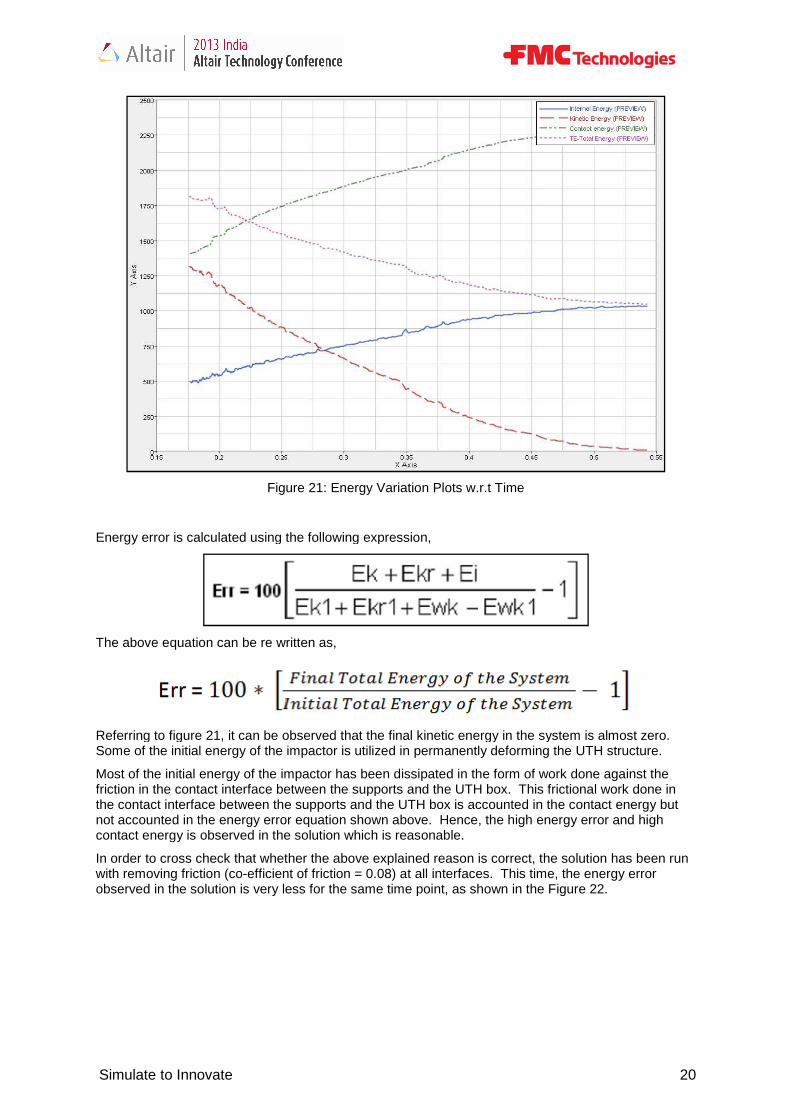
Figure 21: Energy Variation Plots w.r.t Time
Figure 22: Energy Error in the Model without Friction
Simulate to Innovate
List of Figures
Figure 1: Typical Subsea Production Layout ................................................................
gure 2: Umbilical Termination Assembly ................................................................
Figure 3: The UTH & the ROV ................................................................
Figure 4: Geometry Description of the UTH structure ................................
Figure 5: Finite Element Model of the UTH ................................................................
Figure 6: Type 7 Frictional Sliding Interfaces ................................................................
Figure 7: Zoom Views of Type 7 Interfaces ................................................................
Figure 8: Locations of Spot Welds ................................................................
Figure 9: Bolts in the Bolted Flange Interface ................................................................
Figure 10: Stress Strain Curves for the Components of the UTH Box .............................
Figure 11: Loading and Boundary Conditions ................................................................
Figure 12: Boundary Condition ................................................................
Figure 13: Impactor (ROV) Velocity ................................................................
Figure 14: Displacement Plot of the UTH structure .........................................................
Figure 15: Clearance between the UTH Box Pad Eye & the Support Ears
Figure 16: von Mises Plastic Strain Plot in the UTH structure ................................
Figure 17: von Mises Plastic Strain Plot in the Support Ears ................................
Figure 18: von Mises Stress Plot in the UTH structure ................................
Figure 19: von Mises Stress Plot in the Support Ears ................................
Figure 20: von Mises Stress Plot in the Bolts ................................................................
Figure 21: Energy Variation Plots w.r.t Time ................................................................
Figure 22: Energy Error in the Model without Friction ................................
Simulate to Innovate 4
Page
..................................... 6
........................................ 7
.......................................................... 8
....................................................... 9
..................................... 10
.................................. 10
..................................... 11
.................................................. 12
................................. 12
............................. 13
................................. 14
....................................................... 15
................................................ 15
......................... 16
Figure 15: Clearance between the UTH Box Pad Eye & the Support Ears...................... 17
......................................... 17
.......................................... 18
.................................................... 18
..................................................... 19
.................................. 19
................................... 20
..................................................... 21

Simulate to Innovate
The following abbreviations are used throughout this document.
Abbreviation Description
c.o.f Coefficient of FrictionDOF DegreeFEA Finite Element AnalysisUTH Umbilical Termination HeadUTA Umbilical Termination ‘X’ Trees Christmas Treesksi Kilo pounds per square inchSDU Subsea Distribution UnitEDU Electrical Distribution Unitw.r.t with respect toNA Not ApplicableUTS Ultimate Tensile Strength
Simulate to Innovate
Abbreviations
The following abbreviations are used throughout this document.
Description
Coefficient of Friction Degrees of Freedom Finite Element Analysis Umbilical Termination Head Umbilical Termination Assembly Christmas Trees Kilo pounds per square inch Subsea Distribution Unit Electrical Distribution Unit with respect to Not Applicable Ultimate Tensile Strength
Simulate to Innovate 5
Simulate to Innovate
1.0 Introduction
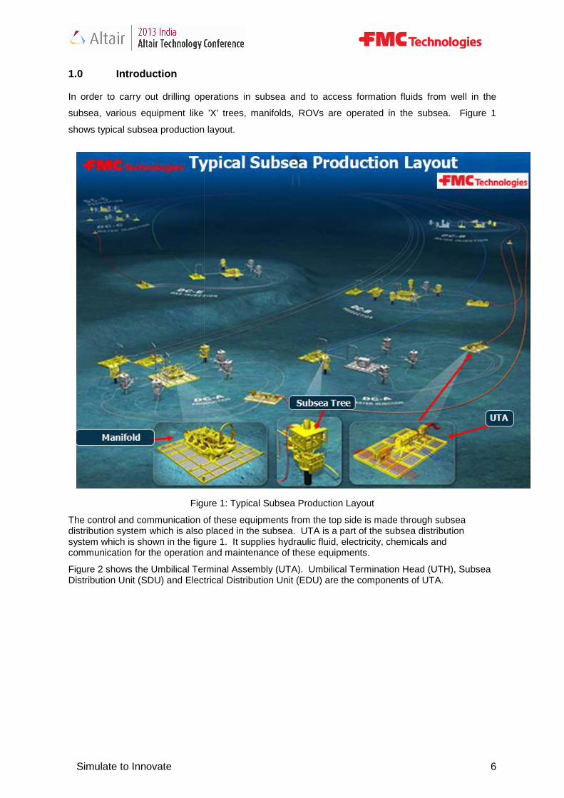
In order to carry out drilling operations in subsea and to access formation fluids from well in the
subsea, various equipment like 'X' trees, manifolds, ROVs are operated in the subsea. Figure 1
shows typical subsea production layout.
Figure
The control and communication of these equipments from the top side is made through subsea distribution system which is also placed in the subsea. UTA is a part of the subsea distribution system which is shown in the figure 1. It supplies hydraulic fluid, electricity, chemicals and communication for the operation and maintenance of these equipments
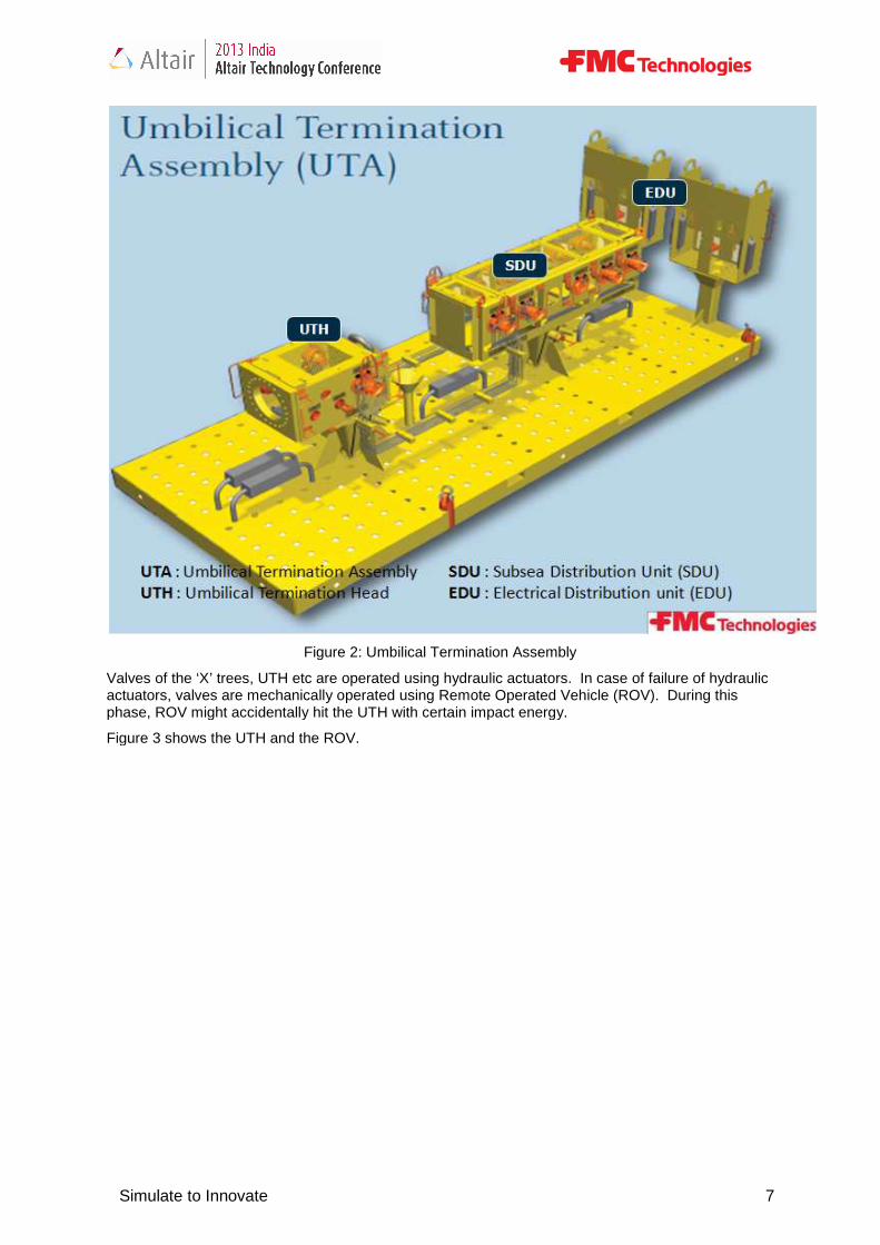
Figure 2 shows the Umbilical Terminal Assembly (UTA). Umbilical Termination Head (UTH), Subsea Distribution Unit (SDU) and Electrical Distribution Unit (EDU) are the components of UTA.
Simulate to Innovate
carry out drilling operations in subsea and to access formation fluids from well in the
subsea, various equipment like 'X' trees, manifolds, ROVs are operated in the subsea. Figure 1
shows typical subsea production layout.
Figure 1: Typical Subsea Production Layout
The control and communication of these equipments from the top side is made through subsea distribution system which is also placed in the subsea. UTA is a part of the subsea distribution
figure 1. It supplies hydraulic fluid, electricity, chemicals and communication for the operation and maintenance of these equipments.
Figure 2 shows the Umbilical Terminal Assembly (UTA). Umbilical Termination Head (UTH), Subsea and Electrical Distribution Unit (EDU) are the components of UTA.
Simulate to Innovate 6
carry out drilling operations in subsea and to access formation fluids from well in the
subsea, various equipment like 'X' trees, manifolds, ROVs are operated in the subsea. Figure 1
The control and communication of these equipments from the top side is made through subsea distribution system which is also placed in the subsea. UTA is a part of the subsea distribution
figure 1. It supplies hydraulic fluid, electricity, chemicals and
Figure 2 shows the Umbilical Terminal Assembly (UTA). Umbilical Termination Head (UTH), Subsea and Electrical Distribution Unit (EDU) are the components of UTA.
Simulate to Innovate
Figure 2:
Valves of the ‘X’ trees, UTH etc are operated using hydraulic actuators. In case of failure of hydraulic actuators, valves are mechanically operatphase, ROV might accidentally hit the UTH with certain impact energy.
Figure 3 shows the UTH and the ROV.
Simulate to Innovate
Figure 2: Umbilical Termination Assembly
‘X’ trees, UTH etc are operated using hydraulic actuators. In case of failure of hydraulic actuators, valves are mechanically operated using Remote Operated Vehicle (ROV). During this phase, ROV might accidentally hit the UTH with certain impact energy.
Figure 3 shows the UTH and the ROV.
Simulate to Innovate 7
‘X’ trees, UTH etc are operated using hydraulic actuators. In case of failure of hydraulic ed using Remote Operated Vehicle (ROV). During this

Simulate to Innovate
It is required to verify whether this impact can affect the reason, UTH needs to be verified for its structural integrity under the action of this impact energy and needs to be qualified as per NORSOK standard (Design of Steel Structures).
To verify possible damage in the UTH structure due tosolver has been chosen to perform finite element analysis.
2.0 Objective
The objective is to simulate the impact made by Remote Operated Vehicle (ROV) on Umbilical Termination Head (UTH) and veri
Structural integrity of the UTH structure is verified by comparing the von Mises plastic strain observed in the structure with the allowable limit specified by NORSOK (Design of Steel Structures).
As per NORSOK, von Mises plastic strain in the structure should not exceed the minimum elongation limit of the structure’s material which is 18
3.0 Model Description
3.1 Geometry
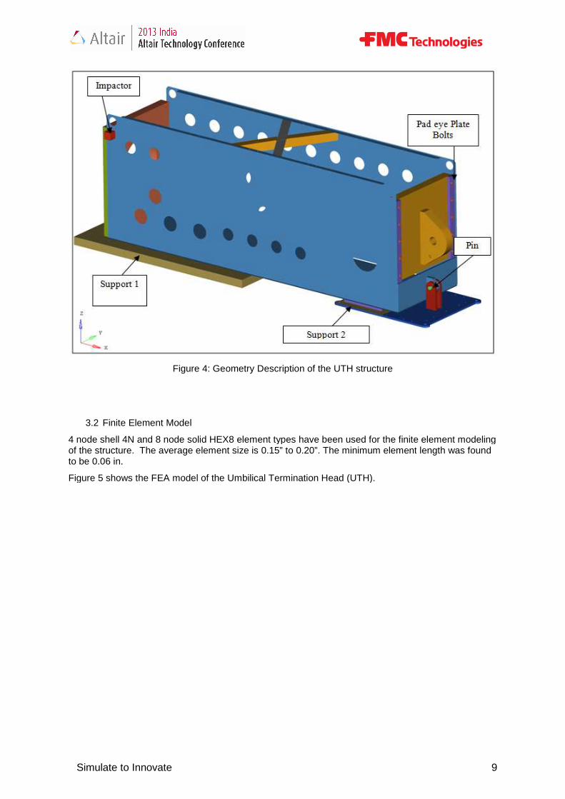
Figure 4 shows the geometry of the Umbilical Termination Head (UTH).
The cross sectional area of the ROV tool with which it impacts the UTH is known. Hence the ROV is modeled as a simple geometry with the known crossof the impactor is adjusted to meet the ROV weight (6600 lbf)
Simulate to Innovate
Figure 3: The UTH & the ROV
It is required to verify whether this impact can affect the functionality of the UTH structure. For this reason, UTH needs to be verified for its structural integrity under the action of this impact energy and needs to be qualified as per NORSOK standard (Design of Steel Structures).
he UTH structure due to impact made by the ROV, RADIOSSsolver has been chosen to perform finite element analysis.
The objective is to simulate the impact made by Remote Operated Vehicle (ROV) on Umbilical Termination Head (UTH) and verify structural integrity of the UTH structure.
Structural integrity of the UTH structure is verified by comparing the von Mises plastic strain observed in the structure with the allowable limit specified by NORSOK (Design of Steel Structures).
OK, von Mises plastic strain in the structure should not exceed the minimum elongation structure’s material which is 18 % in this case.
Model Description
Figure 4 shows the geometry of the Umbilical Termination Head (UTH).
sectional area of the ROV tool with which it impacts the UTH is known. Hence the ROV is modeled as a simple geometry with the known cross-section area and arbitrary depth and t
is adjusted to meet the ROV weight (6600 lbf).
Simulate to Innovate 8
functionality of the UTH structure. For this reason, UTH needs to be verified for its structural integrity under the action of this impact energy and
impact made by the ROV, RADIOSS Explicit
The objective is to simulate the impact made by Remote Operated Vehicle (ROV) on Umbilical
Structural integrity of the UTH structure is verified by comparing the von Mises plastic strain observed in the structure with the allowable limit specified by NORSOK (Design of Steel Structures).
OK, von Mises plastic strain in the structure should not exceed the minimum elongation
sectional area of the ROV tool with which it impacts the UTH is known. Hence the ROV is a and arbitrary depth and the density
Simulate to Innovate
Figure 4
3.2 Finite Element Model
4 node shell 4N and 8 node solid HEX8 element types have been used for the finite element modeling of the structure. The average element size is 0.15” to 0.20”. The minimum elementto be 0.06 in.
Figure 5 shows the FEA model of the Umbilical Termination Head (UTH).
Simulate to Innovate
4: Geometry Description of the UTH structure
4 node shell 4N and 8 node solid HEX8 element types have been used for the finite element modeling of the structure. The average element size is 0.15” to 0.20”. The minimum element
Figure 5 shows the FEA model of the Umbilical Termination Head (UTH).
Simulate to Innovate 9
4 node shell 4N and 8 node solid HEX8 element types have been used for the finite element modeling of the structure. The average element size is 0.15” to 0.20”. The minimum element length was found
Simulate to Innovate
Figure
3.3 Interfaces
Frictional sliding interfaces in the model have been simulated using type 7 interface. the locations of type 7 interfaces.
Figure 6: Type 7 Frictional Sliding Interfaces
Location 1 is the UTH pin (hinge) to pad eyes interface
Simulate to Innovate
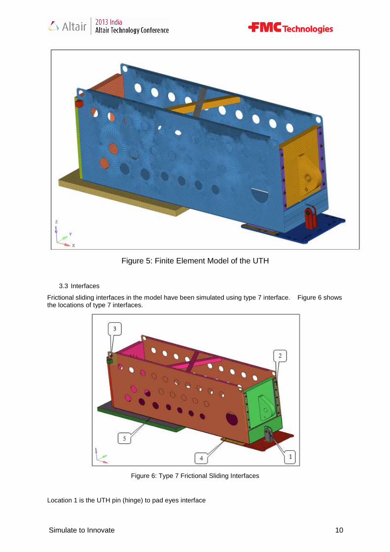
Figure 5: Finite Element Model of the UTH
Frictional sliding interfaces in the model have been simulated using type 7 interface. the locations of type 7 interfaces.
Figure 6: Type 7 Frictional Sliding Interfaces
Location 1 is the UTH pin (hinge) to pad eyes interface
Simulate to Innovate 10
Frictional sliding interfaces in the model have been simulated using type 7 interface. Figure 6 shows
Simulate to Innovate
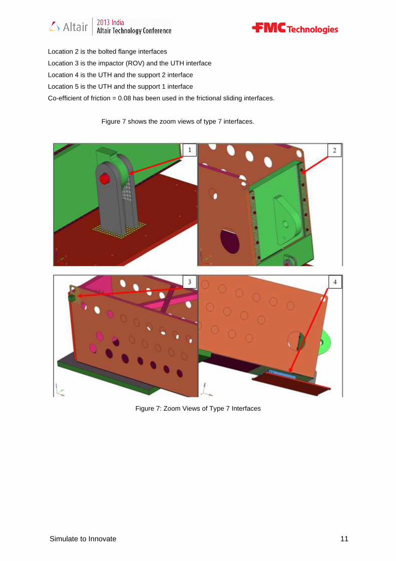
Location 2 is the bolted flange interfaces
Location 3 is the impactor (ROV) and the UTH interface
Location 4 is the UTH and the support 2 interface
Location 5 is the UTH and the support 1 interface
Co-efficient of friction = 0.08 has been used in the
Figure 7 shows the zoom views of type 7 in
Figure 7: Zoom Views of Type 7 Interfaces
Simulate to Innovate
Location 2 is the bolted flange interfaces
Location 3 is the impactor (ROV) and the UTH interface
Location 4 is the UTH and the support 2 interface
Location 5 is the UTH and the support 1 interface
efficient of friction = 0.08 has been used in the frictional sliding interfaces.
Figure 7 shows the zoom views of type 7 interfaces.
Figure 7: Zoom Views of Type 7 Interfaces
Simulate to Innovate 11
Simulate to Innovate
Weld joints are simulated using type 2 contact interfaces and spot welds.
Figure 8 shows the locations of spot welds in green color.
3.4 Bolt Pretension
Bolts are pre tensioned to a value of 7440 lbf.
To simulate pretension in bolts, rigid elements with master node option were created at each end of the bolts (bolt heads) and master nodes of each bolt are connected by SPRING2N elements. /PROP/TYPE32 (SPR_PRE) spring property was used for ramped over the time. The distance of impactor from the impacting surface was adjusted such that the bolt pretension was completely applied before the impact.
Figure 9 shows the bolts in the bolted flange interface.
Figure 9: Bolts in the Bolted Flange Interface
Simulate to Innovate
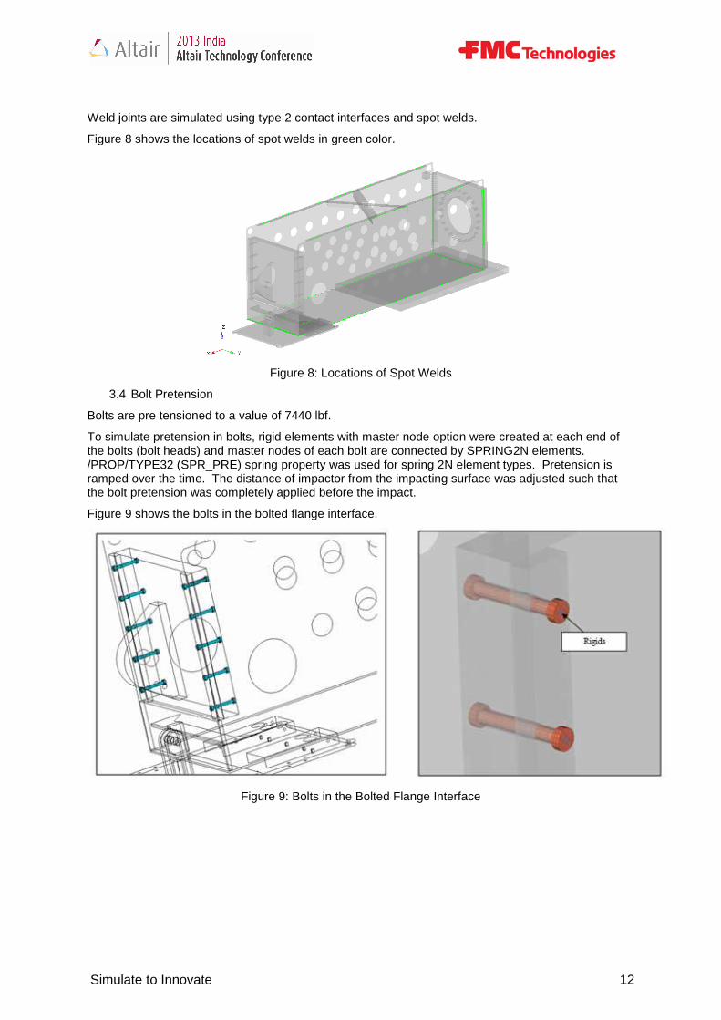
Weld joints are simulated using type 2 contact interfaces and spot welds.
Figure 8 shows the locations of spot welds in green color.
Figure 8: Locations of Spot Welds
Bolts are pre tensioned to a value of 7440 lbf.
To simulate pretension in bolts, rigid elements with master node option were created at each end of the bolts (bolt heads) and master nodes of each bolt are connected by SPRING2N elements.
_PRE) spring property was used for spring 2N element types. Pretension is ramped over the time. The distance of impactor from the impacting surface was adjusted such that the bolt pretension was completely applied before the impact.
bolts in the bolted flange interface.
Figure 9: Bolts in the Bolted Flange Interface
Simulate to Innovate 12
To simulate pretension in bolts, rigid elements with master node option were created at each end of the bolts (bolt heads) and master nodes of each bolt are connected by SPRING2N elements.
2N element types. Pretension is ramped over the time. The distance of impactor from the impacting surface was adjusted such that
Simulate to Innovate
3.5 Materials
All components of UTH are modeled using Elastic Plastic, Multi linear, Isotropic strain hardening material curve generated as per ASME (Boiler and Pressur(PLAS_TAB). Figure 10 shows the stress strain curves for the components of the UTH. Also, Refer table 1 for the material data.
Figure 10: Stress Strain Curves for the Components of the UTH Box
Impactor (ROV) was modeled using linear elastic material with 100 times higher young’s modulus compared to young’s modulus of the UTH. This is a conservative approach in the sense that, during impact, most of the impact energy is absorbed by the UTH in straining itself and not the
Properties
Young's Modulus
Poisson's Ratio
Yield Strength
UTS
Minimum Elongation Limit
Simulate to Innovate
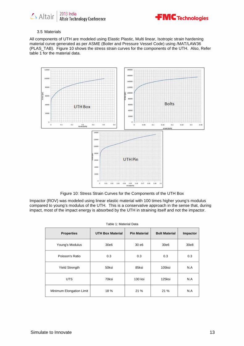
All components of UTH are modeled using Elastic Plastic, Multi linear, Isotropic strain hardening material curve generated as per ASME (Boiler and Pressure Vessel Code) using /MAT/LAW36
Figure 10 shows the stress strain curves for the components of the UTH. Also, Refer
Figure 10: Stress Strain Curves for the Components of the UTH Box
using linear elastic material with 100 times higher young’s modulus compared to young’s modulus of the UTH. This is a conservative approach in the sense that, during impact, most of the impact energy is absorbed by the UTH in straining itself and not the
Table 1: Material Data
UTH Box Material Pin Material Bolt Material
30e6 30 e6 30e6
0.3 0.3 0.3
50ksi 85ksi 105ksi
70ksi 130 ksi 125ksi
18 % 21 % 21 %
Simulate to Innovate 13
All components of UTH are modeled using Elastic Plastic, Multi linear, Isotropic strain hardening e Vessel Code) using /MAT/LAW36
Figure 10 shows the stress strain curves for the components of the UTH. Also, Refer
Figure 10: Stress Strain Curves for the Components of the UTH Box
using linear elastic material with 100 times higher young’s modulus compared to young’s modulus of the UTH. This is a conservative approach in the sense that, during impact, most of the impact energy is absorbed by the UTH in straining itself and not the impactor.
Impactor
30e8
0.3
N.A
N.A
N.A
Simulate to Innovate
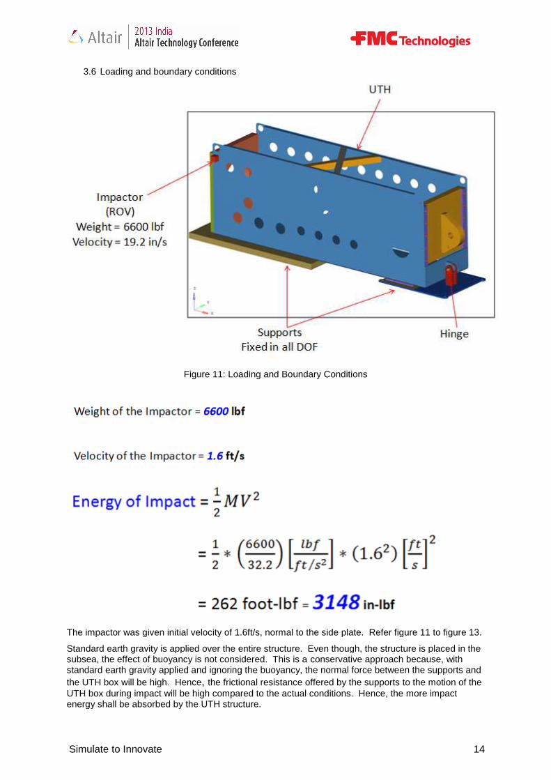
3.6 Loading and boundary conditions
Figure 11: Loading and Boundary Conditions
The impactor was given initial velocity of 1.6ft/s, normal to the side plate. Refer figure 11
Standard earth gravity is applied over the entire structure. Even though, the structure is placed in the subsea, the effect of buoyancy is not considered. This is astandard earth gravity applied and ignoring the buoyancy, the normal force betwthe UTH box will be high. HenceUTH box during impact will be high compared to the actual conditions. Hence, the more impact energy shall be absorbed by the UTH
Simulate to Innovate
Loading and boundary conditions
Figure 11: Loading and Boundary Conditions
The impactor was given initial velocity of 1.6ft/s, normal to the side plate. Refer figure 11
applied over the entire structure. Even though, the structure is placed in the subsea, the effect of buoyancy is not considered. This is a conservative approach because, with standard earth gravity applied and ignoring the buoyancy, the normal force between the supports and the UTH box will be high. Hence, the frictional resistance offered by the supports to the motion of the UTH box during impact will be high compared to the actual conditions. Hence, the more impact energy shall be absorbed by the UTH structure.
Simulate to Innovate 14
The impactor was given initial velocity of 1.6ft/s, normal to the side plate. Refer figure 11 to figure 13.
applied over the entire structure. Even though, the structure is placed in the conservative approach because, with
een the supports and the frictional resistance offered by the supports to the motion of the
UTH box during impact will be high compared to the actual conditions. Hence, the more impact
Simulate to Innovate
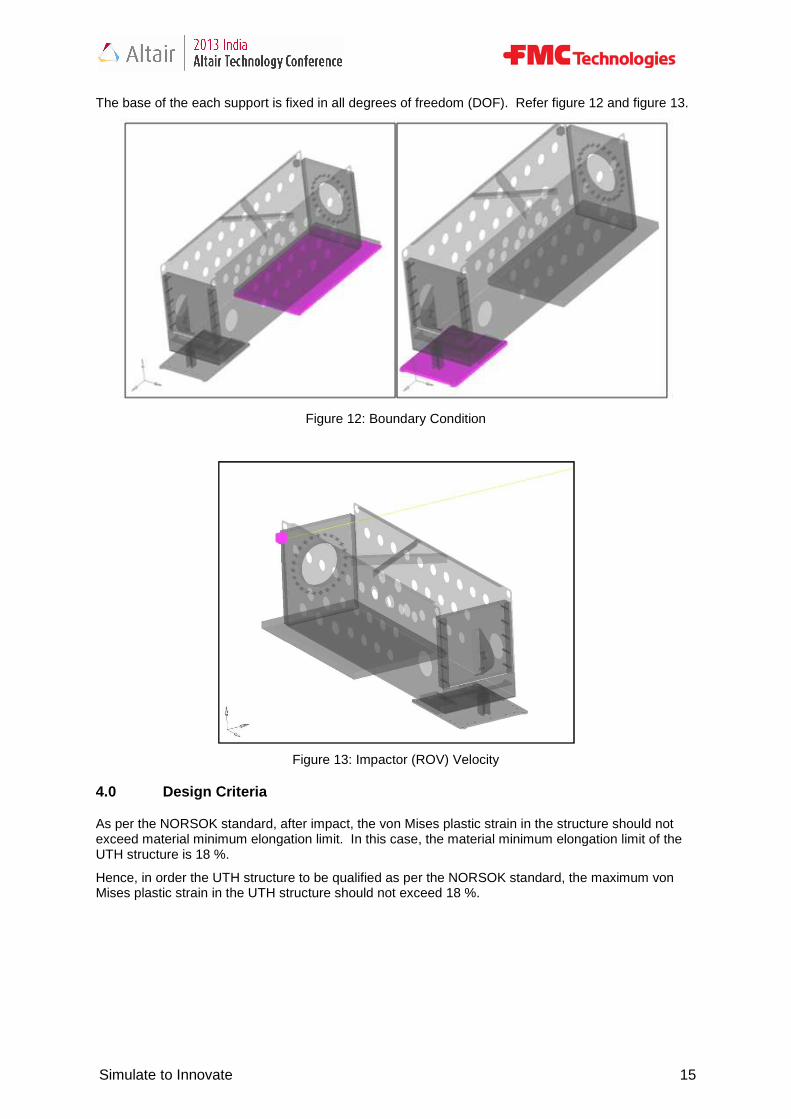
The base of the each support is fixed in all degrees of freedom (DOF). Refer figure 1
4.0 Design Criteria
As per the NORSOK standard, after impact, the von Mises exceed material minimum elongation limit. In UTH structure is 18 %.
Hence, in order the UTH structure to be qualified as per the NORSOK standard, the maximuMises plastic strain in the UTH structure should not exceed 18 %.
Simulate to Innovate
fixed in all degrees of freedom (DOF). Refer figure 1
Figure 12: Boundary Condition
Figure 13: Impactor (ROV) Velocity
As per the NORSOK standard, after impact, the von Mises plastic strain in the structure should not exceed material minimum elongation limit. In this case, the material minimum elongation limit of the
Hence, in order the UTH structure to be qualified as per the NORSOK standard, the maximuMises plastic strain in the UTH structure should not exceed 18 %.
Simulate to Innovate 15
fixed in all degrees of freedom (DOF). Refer figure 12 and figure 13.
plastic strain in the structure should not case, the material minimum elongation limit of the
Hence, in order the UTH structure to be qualified as per the NORSOK standard, the maximum von

Simulate to Innovate
5.0 Results Discussion
The results of the analysis showed that the design of the UTH structure is safe for impact load case.
Figure 14 shows the displacement plot of the structure. Itthe UTH structure, the UTH box starts rotating about the UTH pin (extreme right in the figure) and slides over the supports.
Figure 14: Displacement Plot of the UTH structure
While the UTH box is sliding over thfriction (work done against friction). Hence minimum impact energy has been transferred to the UTH box. So, the maximum von Mises plastic strain observed in the UTH structure is very lesRefer figure 14.
The motion of UTH box is a combination of translational and rotational motion. Translation motion is described by the sliding of the UTH box over the supports. Rotation motion is described by the rotation of the UTH box about the UTH pin which acts as a hinge for the UTH box.
Translation displacement (4”) of the UTH box UTH pin has been seen because of the clearance maintained between the UTH box pad eye and the support ears at the UTH pin location which acts as a hinge. Refer figure 15. Frictional contact interface is defined between the support ears and the UTH box pin. Radial frictional is also defined between the pin and the UTH box pad eye, support ears. Refer figure 15. displacement (4”) in the UTH box work against the friction between the suppo
Simulate to Innovate
Results Discussion
The results of the analysis showed that the design of the UTH structure is safe for impact load case.
Figure 14 shows the displacement plot of the structure. It explains that, as the impactor (ROV) hits the UTH structure, the UTH box starts rotating about the UTH pin (extreme right in the figure) and
Figure 14: Displacement Plot of the UTH structure
While the UTH box is sliding over the supports, most of the impact energy is utilized in overcoming the friction (work done against friction). Hence minimum impact energy has been transferred to the UTH box. So, the maximum von Mises plastic strain observed in the UTH structure is very les
The motion of UTH box is a combination of translational and rotational motion. Translation motion is described by the sliding of the UTH box over the supports. Rotation motion is described by the
the UTH pin which acts as a hinge for the UTH box.
of the UTH box and rotation displacement of the UTH box because of the clearance maintained between the UTH box pad eye and the
support ears at the UTH pin location which acts as a hinge. Refer figure 15. Frictional contact interface is defined between the support ears and the UTH box pin. Radial frictional is also defined between the pin and the UTH box pad eye, support ears. Refer figure 15.
UTH box structure helped in dissipating most of the impact energy by doing work against the friction between the supports and the UTH box interface.
Simulate to Innovate 16
The results of the analysis showed that the design of the UTH structure is safe for impact load case.
explains that, as the impactor (ROV) hits the UTH structure, the UTH box starts rotating about the UTH pin (extreme right in the figure) and
e supports, most of the impact energy is utilized in overcoming the friction (work done against friction). Hence minimum impact energy has been transferred to the UTH box. So, the maximum von Mises plastic strain observed in the UTH structure is very less (0.2 %).
The motion of UTH box is a combination of translational and rotational motion. Translation motion is described by the sliding of the UTH box over the supports. Rotation motion is described by the
the UTH pin which acts as a hinge for the UTH box. Refer figure 14.
of the UTH box about the because of the clearance maintained between the UTH box pad eye and the
support ears at the UTH pin location which acts as a hinge. Refer figure 15. Frictional contact interface is defined between the support ears and the UTH box pin. Radial frictional contact interface is also defined between the pin and the UTH box pad eye, support ears. Refer figure 15. This
structure helped in dissipating most of the impact energy by doing
Simulate to Innovate
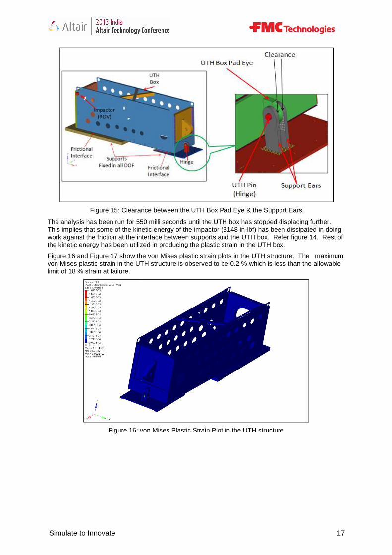
Figure 15: Clearance between the UTH Box Pad Eye & the Support Ears
The analysis has been run for 550 milli seconds until the UTH box has stopped displacing further. This implies that some of the kinetic energy of the work against the friction at the interface between supports and the UTH box. the kinetic energy has been utilized in producing the plastic strain in the UTH box.
Figure 16 and Figure 17 show the von Mises plastic strain plots in the UTH structure. The maximum von Mises plastic strain in the UTH structure is observed to be 0.2 % which is less than the allowable limit of 18 % strain at failure.
Figure 16: von Mises Plastic Str
Simulate to Innovate
Figure 15: Clearance between the UTH Box Pad Eye & the Support Ears
550 milli seconds until the UTH box has stopped displacing further. This implies that some of the kinetic energy of the impactor (3148 in-lbf) has been dissipated in doing work against the friction at the interface between supports and the UTH box. Refer figure 14. the kinetic energy has been utilized in producing the plastic strain in the UTH box.
igure 17 show the von Mises plastic strain plots in the UTH structure. The maximum von Mises plastic strain in the UTH structure is observed to be 0.2 % which is less than the allowable
Figure 16: von Mises Plastic Strain Plot in the UTH structure
Simulate to Innovate 17
Figure 15: Clearance between the UTH Box Pad Eye & the Support Ears
550 milli seconds until the UTH box has stopped displacing further. lbf) has been dissipated in doing
Refer figure 14. Rest of the kinetic energy has been utilized in producing the plastic strain in the UTH box.
igure 17 show the von Mises plastic strain plots in the UTH structure. The maximum von Mises plastic strain in the UTH structure is observed to be 0.2 % which is less than the allowable
ain Plot in the UTH structure

Simulate to Innovate
Figure 17: von Mises Plastic Strain Plot in the Support Ears
Figure 18 to Figure 20 show the von Mises stress plots in the UTH structure
Figure 18: von Mises Stress Plot in the UTH structure
Simulate to Innovate
Figure 17: von Mises Plastic Strain Plot in the Support Ears
Figure 18 to Figure 20 show the von Mises stress plots in the UTH structure
Figure 18: von Mises Stress Plot in the UTH structure
Simulate to Innovate 18
Figure 18 to Figure 20 show the von Mises stress plots in the UTH structure.
Simulate to Innovate
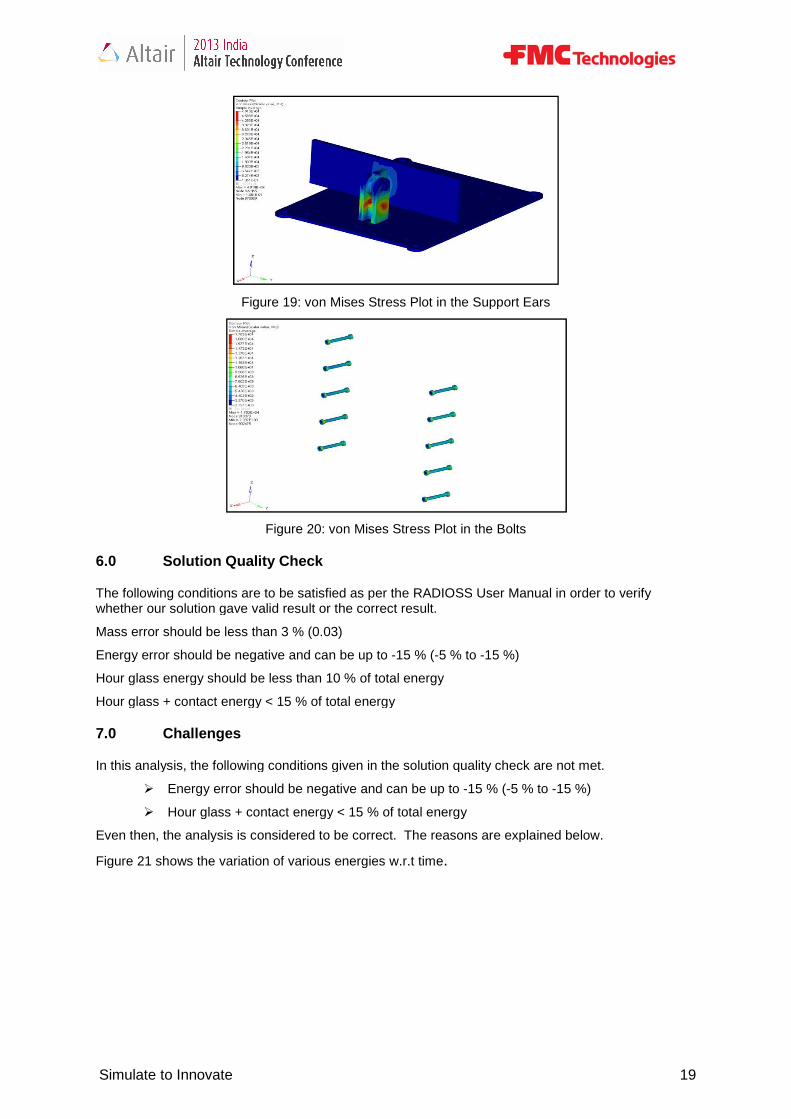
Figure 19: von Mises Stress Plot in the Support Ears
Figure 20: von Mises Stress Plot in the Bolts
6.0 Solution Quality Check
The following conditions are to be satisfied as per the RADIOSSwhether our solution gave valid result or the correct result.
Mass error should be less than 3 % (0.03)
Energy error should be negative and can be up to
Hour glass energy should be less than 10 % of tot
Hour glass + contact energy < 15 % of total energy
7.0 Challenges
In this analysis, the following conditions given in the solution quality check are not met.
� Energy error should be negative and can be up to
� Hour glass + contact energy < 15 % of total energy
Even then, the analysis is considered to be correct. The reasons are explained below.
Figure 21 shows the variation of various energies w.r.t time
Simulate to Innovate
19: von Mises Stress Plot in the Support Ears
Figure 20: von Mises Stress Plot in the Bolts
Solution Quality Check
be satisfied as per the RADIOSS User Manual in order to verify whether our solution gave valid result or the correct result.
Mass error should be less than 3 % (0.03)
Energy error should be negative and can be up to -15 % (-5 % to -15 %)
Hour glass energy should be less than 10 % of total energy
Hour glass + contact energy < 15 % of total energy
In this analysis, the following conditions given in the solution quality check are not met.
Energy error should be negative and can be up to -15 % (-5 % to -15 %)
Hour glass + contact energy < 15 % of total energy
Even then, the analysis is considered to be correct. The reasons are explained below.
Figure 21 shows the variation of various energies w.r.t time.
Simulate to Innovate 19
User Manual in order to verify
In this analysis, the following conditions given in the solution quality check are not met.
15 %)
Even then, the analysis is considered to be correct. The reasons are explained below.
Simulate to Innovate
Figure 21: Energy Variation Plots w.r.t Time
Energy error is calculated using the following expression,
The above equation can be re written as,
Referring to figure 21, it can be observed that the final kinetic energy in the sSome of the initial energy of the impactor is utilized
Most of the initial energy of the impactor friction in the contact interface between the supports and the UTH box. This frictional work done in the contact interface between the supports and the UTH box is accounted in the contact energy but not accounted in the energy error contact energy is observed in the solution which is reasonable.
In order to cross check that whether with removing friction (co-efficient of friction = 0.08observed in the solution is very less for
Simulate to Innovate
Figure 21: Energy Variation Plots w.r.t Time
error is calculated using the following expression,
The above equation can be re written as,
Referring to figure 21, it can be observed that the final kinetic energy in the system is almost zero. of the impactor is utilized in permanently deforming the UTH structure.
t of the initial energy of the impactor has been dissipated in the form of work done against the friction in the contact interface between the supports and the UTH box. This frictional work done in
t interface between the supports and the UTH box is accounted in the contact energy but error equation shown above. Hence, the high energy error and high
contact energy is observed in the solution which is reasonable.
to cross check that whether the above explained reason is correct, the solution has been run efficient of friction = 0.08) at all interfaces. This time, the energy error
ed in the solution is very less for the same time point, as shown in the Figure 22.
Simulate to Innovate 20
ystem is almost zero.
in permanently deforming the UTH structure.
has been dissipated in the form of work done against the friction in the contact interface between the supports and the UTH box. This frictional work done in
t interface between the supports and the UTH box is accounted in the contact energy but . Hence, the high energy error and high
above explained reason is correct, the solution has been run the energy error
point, as shown in the Figure 22.

Simulate to Innovate
Figure 22:
8.0 ACKNOWLEDGEMENTS
The authors would like to thank Altair Engineering, India for providing technical support and bringing experts to FMC India office to build a strong
9.0 REFERENCES
[1] Altair Engineering, RADIOSS user manual
[2] Practical Finite Element Analysis, Nitin S. Gokhale, Sanjay S. Deshpande, Sanjeev V. Bedekar,Dr. Anand N. Thite
[3] NORSOK, Design of Steel Structures
[4] American Society of Mechanical Engineers
Simulate to Innovate
Figure 22: Energy Error in the Model without Friction
ACKNOWLEDGEMENTS
The authors would like to thank Altair Engineering, India for providing technical support and bringing experts to FMC India office to build a strong team in explicit simulation in Altair RADIOSS
RADIOSS user manual
Nitin S. Gokhale, Sanjay S. Deshpande, Sanjeev V. Bedekar,Dr. Anand N. Thite
Structures
[4] American Society of Mechanical Engineers (ASME)
Simulate to Innovate 21
The authors would like to thank Altair Engineering, India for providing technical support and bringing cit simulation in Altair RADIOSS.
Nitin S. Gokhale, Sanjay S. Deshpande, Sanjeev V. Bedekar,Dr. Anand N. Thite