simulation of soot filtration in diesel particulate filter
TRANSCRIPT

© Math2Market GmbH
Math2Market GmbH, Kaiserslautern, Germany
Dr.-Ing. Mehdi Azimian, Dr. Liping Cheng, Dr. Andreas Wiegmann
Simulation of soot filtration in diesel particulate filter with GeoDict
15th FAD-Conference "Challenge- Exhaust Aftertreatment for Diesel Engines"
8.-9. November 2017, Dresden, Germany
© Math2Market GmbH3
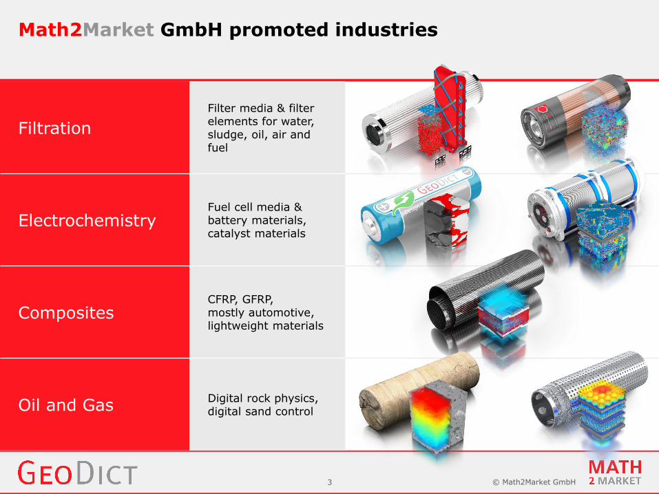
Math2Market GmbH promoted industries
Filtration
Filter media & filter elements for water, sludge, oil, air and fuel
ElectrochemistryFuel cell media & battery materials, catalyst materials
CompositesCFRP, GFRP, mostly automotive, lightweight materials
Oil and GasDigital rock physics, digital sand control

© Math2Market GmbH4
With GeoDict you can...
Analyse MaterialsµCT & FIB-SEM Import Optimize Materials
varyparameters
Model Materials Export MaterialsAnalyse Properties
GeoDict introduction

© Math2Market GmbH5
Media models, pleat models and filter models

© Math2Market GmbH6
Simulate filtration at different scales
Unresolved media
Resolved media
Unresolved media
Resolved media

© Math2Market GmbH7
Create cellulose and layered media scale models
Cellulose nonwoven Layered filter medium

© Math2Market GmbH8
Create woven, foam and sintered media scale models
Metal wire mesh Open-cell foam Sintered ceramic

© Math2Market GmbH9
Model a desalination membrane from a SEM image
http://www.geodict.com/Showroom/structures.php

© Math2Market GmbH10
Modeling & simulation of soot filtration

© Math2Market GmbH11
Goal:
Design & improve Diesel/Gasoline Particulate Filters (DPF/GPF) through fast simulations.
lower pressure drop
higher filter efficiency
longer life time
Key element governing the performance
of the DPF:
Ceramic filter media
Introduction to Diesel Particulate Filter (DPF)

© Math2Market GmbH12
Energy use of the DPF:
▪ Pressure loss across the (loaded) ceramic walls
▪ Pressure loss along the channels
Step 1: Simulate pressure loss & solid loading across the wall
Step 2: Simulate pressure loss & solid loading along the channels
Diesel Particulate Filter (DPF) simulations
Simulations: 256 x 256 x 750 cellsGrid cells: 0.9 µm x 0.9 µm x 0.9 µmSoot particle: 25 nm - 600 nmWall thickness: 567 µmInlet / Flow Channel: 108µm
567 µm

© Math2Market GmbH13
Step 1Simulate pressure loss across the ceramic wall

© Math2Market GmbH14
Micro-structure
Image acquisition: µ-CT
(+) Allows simulations on real filter structures
(-) Modification of the filter structure is notpossible only through µ-CT images
Modelling with GeoDictstructure generator
modules

© Math2Market GmbH15
Modelling of packed beds of spheres.
Modelling of sintered ceramics.
Modelling of catalyst layer and microporous layer in PEM fuel cells.
Modelling of lithium ion cathodes and other battery materials.
Modelling of rocks like sand-stone.
Modelling of sphere packings with very high packing density.
Micro-structure models with GrainGeo module

© Math2Market GmbH16
Ceramic model characterization
Characterizing the ceramic withPoroDict
Evaluation of the pore size distribution & percolation path
Maximum particlediameter [µm]
Path length [µm]
9.94 929.1

© Math2Market GmbH17
Ceramic model characterization
Characterizing the ceramic withFlowDict
➢ Domain size: 256x256x630 Voxels
➢ Voxel length: 0.9 µm
➢ Ceramic porosity: 48.7 %
➢ Pressure drop is 252.8 Pa at mean airflow velocity of 0.04 m/s
➢ Flow resistivity: 1.115e+07 kg/(m3s)
➢ Permeability: 1.63e-12 m2

© Math2Market GmbH18
Filter life time simulation with FilterDict-Media
4. Deposit particles 5. Update flow field 6. Repeat ...
1. Model filter 2. Compute flow field 3. Track particles

© Math2Market GmbH19
Analysis of cermaic filter performance
Analysis of the filtrationperformance withFilterDict-Media
Simulation of soot particlesdeposition.
Evaluation of fractional filterefficiency.
Evaluation of pressure drop in depth filtration & cake filtrationregimes.

© Math2Market GmbH20
▪ Soot particles (25~600 nm) are smaller than the grid size.
▪ Deposited particles do not fill the computational cell, but form a permeable media.
▪ Define how much a cell can get filled: 𝑓𝑚𝑎𝑥
▪ Define flow resistivity depending on the degree of filling: 𝜎(𝑓)
Filtration of unresolved particles:Solid, empty, or porous (& permeable) grid cells

© Math2Market GmbH21
Error bars induced by5 measurements and 5 different realizations of the digital structure.
Match achieved by introducing different parameters 𝑓𝑚𝑎𝑥 & 𝜎 𝑓for depth & cake filtration.
Experimental and simulated pressure drop evolution
L. Cheng et al., WFC 11, 2012.

© Math2Market GmbH22
Soot deposited on a grid frame- resolved soot simulation to
identify:𝑓𝑚𝑎𝑥 & 𝜎𝑚𝑎𝑥 for cake filtration
Soot deposited in ceramic DPF
- soot as porous media simulation
requires: 𝑓𝑚𝑎𝑥 maximum soot packing density 𝜎𝑚𝑎𝑥 corresponding flow resistivity Soot deposited on a single grain
- resolved soot simulation toapproximate:
𝑓𝑚𝑎𝑥 & 𝜎𝑚𝑎𝑥 for depth filtration
Particle filtration multi-scale approach

© Math2Market GmbH23
Spatial particles deposition over time

© Math2Market GmbH24
After fast initial pressure drop increase (slope s1, depth filtration phase) follows long slower pressure drop increase (slope s2, cake filtration phase)
Matched experiment with simulations
Shortened depth phase to lower pressure drop during cake phase
Fraunhofer IKTS manufactured ceramic, experiment matched simulations, and patent was granted: Particulate filter, No. DE102012220181 A1
Reduced pressure drop over time
s2s1
x
depth filtration
cake filtration

© Math2Market GmbH25
Step 2Simulate pressure loss along the channels

© Math2Market GmbH26
Pressure drop along channels (FlowDict)
Required input:
Permeability of ceramic wall from micro-scale simulation

© Math2Market GmbH27
Soot filtration on DPF honeycomb (FilterDict-Element)
Required input:
Permeability of ceramic wall from micro-scale simulation
Filter efficiency ofeach particle size
Maximum packing density & corresponding flow resistivity

© Math2Market GmbH28
Modeling & simulation at unresolved media scale

© Math2Market GmbH29
1. Simulate pressure drop & soot loading across the ceramic wall
▪ Model ceramic materials
▪ Determine pressure drop evolution and soot loading
2. Simulate pressure drop & soot loading along the channels
▪ Model honeycomb structures
▪ Determine pressure drop evolution and soot loading
Multi-scale simulations bridge the scales between filter media design & filter element design
Developed an improved DPF with Fraunhofer IKTS(patent granted)
Summary

© Math2Market GmbH30
Thank you for your attention.