simulation of speed tracking for brushless dc … · it is quite hard and difficult to tune the...
TRANSCRIPT

SIMULATION OF SPEED TRACKING FOR BRUSHLESS DC MOTOR USING
FUZZY LOGIC CONTROLLER
AFIFAH BINTI ALIR
A project report submitted in partial fulfillment of the
requirement for the award of the degree
Master of Electrical Engineering
Faculty of Electrical and Electronic Engineering
University Tun Hussein Onn Malaysia
JULY 2013

vi
ABSTRACT
Brushless DC motors are normally used in an automotive application,
robotics, medical, industrial automation equipment and machine tools due to its
advantages. The advantages are long life operation, easy to construct, noiseless
operation and has a better speed performance. This project presents a simulation
model for BLDC motor using MATLAB/Simulink. Usually, the speed control is
achieved by using PI controller. Then, the dynamic response of the BLDC motor
such as speed, torque as well as current and voltage are observed and been analyzed
using the MATLAB model. It is quite hard and difficult to tune the conventional PI
controller parameters. Therefore, a suitable speed controller is been developed by
using MATLAB Fuzzy Logic tool box. The objectives of this project are to minimize
the maximum overshoot (%OS), settling time (Ts) and also peak time (Tp). Besides,
the purpose is to improve the speed performance of the motor drive system. In order
to verify the effectiveness of the controller, both control algorithms (Fuzzy logic
control and PID) are compared. The simulation results show that the FLC controller
has better performance which has reduced and minimized the percentage of
maximum overshoot, settling time, peak time and rise time compared with the used
of conventional PI controller.

vii
ABSTRAK
Motor arus terus tanpa berus (BLDC) kebiasaanya digunakan di dalam
bidang automotif, robot, perubatan, peralatan automotif industri dan peralatan mesin
disebabkan oleh kelebihan motor tersebut. Antara kelebihannya adalah untuk jangka
hayat operasi yang lama dan panjang, mudah dibina, tidak terlalu bising serta
mempunyai prestasi kelajuan yang baik. Projek ini memaparkan model simulasi
motor arus terus tanpa berus menerusi aplikasi penggunaan MATLAB/Simulink.
Kebiasaannya, kawalan kelajuan dicapai menggunakan kawalan PI. Kemudian tindak
balas dinamik motor arus terus tanpa berus seperti kelajuan, tork, termasuk juga arus
dan voltan diperhatikan dan dianalisa menggunakan modul MATLAB. Bagi melaras
konvensional kawalan PI adalah agak rumit dan sukar. Oleh yang demikian,
kesesuaian kawalan kelajuan telah dibina menggunakan perkakasan MATLAB
pengatur logik kabur. Tujuan projek ini ialah untuk menggurangkan lanjakkan
(%OS), masa tetapan (Ts) dan juga masa puncak (Tp). Selain itu, adalah tujuannya
untuk membaiki prestasi kelajuan system pemajuan motor. Bagi memastikan
keberkesanan kawalan, kedua-dua kawalan algoritma (pengatur logic kabur dan PID)
dibandingkan. Simulasi menunjukkan kawalan FLC mempunyai prestasi yang baik
di mana ianya dapat meminimakan serta mengurangkan peratusan lanjakkan
maksimum, tetapan masa, masa puncak dan masa meningkat jika dibandingkan
dengan penggunaan konvensional kawalan PI.
viii
CONTENTS
TITLE i
DECLARATION iii
DEDICATION iv
ACKNOWLEDGEMENT v
ABSTRACT vi
ABSTRAK vii
TABLE OF CONTENTS viii
LIST OF FIGURES x
LIST OF TABLES xii
LIST OF ABBREVIATIONS xiii
CHAPTER 1 INTRODUCTION
1.1 Research background 1
1.2 Problem statement 4
1.3 Objectives of the project 5
1.4 Scope of project 5
1.5 Thesis outline 6
CHAPTER 2 LITERATURE REVIEW
2.1 Technology developments 7
2.1.1 Speed control of BLDC motor using adaptive 7
Fuzzy PID controller
2.1.2 Simulation of a variable speed brushless DC 8
motor using Neural Network controller
2.1.3 Fuzzy controller in induction motor speed 8
control with constant flux
2.1.4 Real time implementation of DSP based fuzzy 9
logic controller for speed control of BLDC motor
2.2 Operation of BLDC motor 10
2.2.1 BLDC motor construction and operating principles 11
ix
2.2.2 Mathematical equations of BLDC motor 13
2.3 Fuzzy logic controller system 18
2.4 PID controller systems 22
2.4.1 Tuning PID parameters 23
CHAPTER 3 METHODOLOGY
3.1 Introduction 25
3.2 System structure 28
3.2.1 BLDC motor modeling 28
3.2.2 Structure of speed control system for BLDC motor 30
3.3 Proportional-Integral (PI) controller design 33
3.4 Proposed controller 35
3.5 Fuzzy logic controller design 36
3.5.1 Fuzzification interface 38
3.5.2 Fuzzy rule base 42
3.5.3 Fuzzy inference mechanism 44
3.5.4 Defuzzification 44
CHAPTER 4 RESULT AND ANALYSIS
4.1 Introduction 45
4.2 System performance without controller 47
4.3 Motor drive system with PI controller 49
4.4 Motor drive system with Fuzzy logic controller 56
4.5 Discussions 65
CHAPTER 5 CONCLUSION AND RECOMMENDATION
5.1 Conclusion 66
5.2 Recommendations 67
REFERENCES 68
VITA 72
APPENDIX A: BLDC motor system without controller 73
APPENDIX B: BLDC motor system with PI controller 74
APPENDIX C: BLDC motor with Fuzzy logic controller in 75
MATLAB/Simulink
x
LIST OF FIGURES
2.1 BLDC motor transverse section 11
2.2 DC motor model 13
2.3 BLDC motor block diagram 15
2.4 Configuration of BLDC motor and VSI system 15
2.5 Fuzzy logic controller block diagram 19
2.6 Membership function of fuzzy controller 19
2.7 Schematic model of PID controller 22
3.1 Flow chart overall design of research 26
3.2 BLDC motor modeling in MATLAB/Simulink 28
3.3 Block diagram for BLDC motor speed control 30
3.4 Schematic model for BLDC motor with PI controller 33
3.5 Block diagram of proposed controller 35
3.6 Block diagram of fuzzy logic controller 36
3.7 Flow chart of designing FLC 37
3.8 FIS editor 39
3.9(a) First input variable named “error” 40
3.9(b) Second input variable named “change of error” 40
3.9(c) Output variable “output” 40
3.10 Rule editor structure 42
4.1 BLDC motor system without controller 47
4.2 BLDC motor response without controller 48
4.3 BLDC motor system with PI controller 49
4.4 Reference speed of 3000rpm with no load for PI controller 50
4.5 Reference speed of 3000rpm with load for PI controller 51
xi
4.6 Step up speed of 2500-3000 rpm with no load for PI controller 52
4.7 Step up speed of 2500-3000 rpm with load for PI controller 52
4.8 Step down speed of 3000-2500 rpm with no load for PI controller 53
4.9 Step down speed of 3000-2500 rpm with load for PI controller 54
4.10 BLDC motor with fuzzy logic controller in MATLAB/Simulink 56
4.11 Reference speed of 3000 rpm with no load for fuzzy logic 57
controller
4.12 Reference speed of 3000 rpm with load for fuzzy logic 58
controller
4.13 Reference speed of 1500 rpm with no load for fuzzy logic 58
controller
4.14 Reference speed of 1500 rpm with load for fuzzy logic controller 59
4.15 Step up speed of 2500-3000 rpm with no load for fuzzy logic 60
controller
4.16 Step up speed of 1000-1500 rpm with no load for fuzzy logic 60
controller
4.17 Step up speed of 2500-3000 rpm with load for fuzzy logic 61
controller
4.18 Step up speed of 1000-1500 rpm with load for fuzzy logic 62
controller
4.19 Step down speed of 3000-2500 rpm with load for fuzzy logic 63
controller

xii
LIST OF TABLES
2.1 Motor types comparison 10
2.2 Rule base of FLC 21
2.3 Rules for hand-tuning in PID controller 23
2.4 Rules for Zeigler-Nichols 24
3.1 Parameter of BLDC motor drive system 29
3.2 Clockwise rotation 32
3.3 Gate logic to transform electromagnetic forces 32
3.4 Rule base of fuzzy controller (membership 3x3) 43
3.5 Rule base of fuzzy controller (membership 5x5) 43
3.6 Rule base of fuzzy controller (membership 7x7) 43
4.1 Performance result of conventional PI controller 55
4.2 Performance result of fuzzy logic controller 64

xiii
LIST OF ABBREVIATIONS
DC - Direct current
BDCM - Brushed DC Motor
BLDCM - Brushless DC Motor
PMSM - Permanent Magnet Synchronous Motor
EMF - Electromotive Force
PWM - Pulse Width Modulation
PID - Proportional Integral Derivative
PI - Proportional Integral
FLC - Fuzzy Logic Controller
FC - Fuzzy Controller
MP - Maximum Peak overshoot
OS% - Percentage of Overshoot
eSS - Steady state error
Ts - Settling time
Tr - Rise time
Tp - Peak time
xiv
Ia(t) - Motor current
Va - Armature Voltage
Ra - Armature resistance
La - Armature inductance
Tm - Motor torque
Jm - Motor inertia
Bm - Damping ratio / Viscous friction coefficient
Km - Torque constant
KB - Back EMF constant
Θ - Angular speed
ω - Speed
Kp - Proportional gain
K i - Integral gain
Kd - Derivative gain
Ku - Ultimate gain
Tu - Ultimate time
TI - Integral time
TD - Derivative time
u(t) - Control signal
rpm - Revolution per minute
CHAPTER 1
INTRODUCTION
This chapter will focus on the introduction of the project to be carried out. The
important overview or description including the problem statement, objectives of the
project, and project scopes are well emphasized in this part.
1.1 Research background
The system which is used to control the electric motor is called as an electric drive
system. An electric drive system is the electromechanical that converts electrical
energy to the mechanical energy of the driven machine. The main components of a
modern electric drive system are the motors, power processor, control unit and
electrical source. The purpose of using an electric drive system is to control the speed
and torque of the electric motors. Theoretically, there are two mainly types of direct
current (DC) motors used in the industry. The first one is the conventional brushed
dc (BDC) motor. This type of dc motor is produced a flux by the current through the
field coil of the stationary pole structure. The second type is the brushless dc (BLDC)
motor where the permanent magnet provides the necessary air gap flux instead of the
wire wound field poles. BLDC motor is conventionally defined as a permanent

2
magnet synchronous motor (PMSM) with a trapezoidal back EMF (electromotive
force) waveform shape. As the name implies, BLDC motors do not use brushes for
commutation, instead they are electronically commutated [1].
According to the journal that been done by Lee and Pang (1994), a permanent
magnet brushless dc motor is inside out construction of DC motor. The efficiency is
likely to be higher than the DC motor of equal size and the absence of commutator
and brushes, reduces the motor length. Hence, the lateral stiffness of the motor is
increased, allowing for the high speeds. The power electronic converters required in
a brushless dc motor are similar in topology to the Pulse Width Modulation (PWM)
inverter used in induction motor drives.
Recently, BLDC motors are very popular compared with the brushed DC
motors. In short, BLDC motors have some advantages over conventional brushed DC
motors and induction motor. Some of these advantages are better speed versus torque
characteristics, high dynamic response, high efficiency, high power density, long
operating life, noiseless operations and has higher speed ranges. In addition, BLDC
motors are reliable, easy to control, low maintenance and it is inexpensive [2], [3],
[4]. Due to their favourable electrical and mechanical properties, thus they are widely
used in servo applications such as automotive, aerospace, medical instrumentation,
robotics, machine tools, textile, industry automation equipment and many more as
studied by researchers like Lee and Ehsani (2003). The small sized of motors with
external rotors are widely used in visual equipment such as computer disc drives,
tape recorders and digital audio tapes [5]. BLDC motors are one of the motor types
rapidly gaining popularity. Therefore, the motor must be controlled precisely so that
it will give the desired performance in all these applications.
The classical Proportional-Integral-Derivative (PID) controllers are
commonly used in industries due to their simplicity and ease of implementation [6].
The classical controllers need an accurate mathematical model of the system, can
perform well and resulting good control performances only under linear system
model. Since the BLDC motor drive is highly coupled non-linear multivariable
system, it is difficult to obtain its accurate mathematical model. Besides, a control
performance of the PID controller becomes poor and difficult to determine the
3
controller parameters. To tune the PID control parameters are very difficult and poor
robustness [7].
For this reason, an intelligence controller such as fuzzy logic controller is
needed to improve the control performance of the BLDC motor drive. Fuzzy logic
controller (FLC) has many advantages over conventional control. The fuzzy logic
controller is capable of providing the high accuracy required by the high
performance drive system without the need of mathematical model. FLC
accommodates non-linearity without utilization of mathematical modeling [8].
Therefore, it is less sensitive to the changes of the system parameter. Design
objectives that are difficult to express mathematically can be easily incorporated in a
fuzzy controller by using linguistic rules. In addition, its implementation is simple
and straight forward [9]. It is suitable for applications such as the speed control of
DC motor which has nonlinearities.
In this project, a complete simulation model with fuzzy logic control (FLC)
method for BLDC motor drive is proposed using MATLAB/Simulink.
MATLAB/Simulink simulation model is built to study the dynamic response of
speed for the BLDC motor and the performance of proposed controller. Based on the
simulation result, the develop FLC has the ability to adapt its own controller
parameters based on external disturbance and internal variation of the converter by
giving a minimum peak overshoot (Mp), low value of the steady state error (ess),
settling time (Ts) and rise time (Tr) of the output voltage.
4
1.2 Problem statement
Nowadays, an accurate speed control demand is increased due to research for better
and modern intelligent motion applications in the electrical engineering industry. The
conventional control scheme such as proportional (P), proportional integral (PI) and
proportional integral derivative (PID) have been developed to control the speed of
the brushless dc motor. According by Ramesh et al., (2011) has stated that “..Up to
now, over 80% of the controllers are PI (Proportional and Integral) controllers
because they are facile and easy to understand. The speed controllers are the
conventional PI controllers while current controllers are the P controllers to achieve
high performance drive...”.
Usually, speed control is achieved by using proportional-integral (PI)
controller. Although conventional PI controllers are widely used in the industry due
to their simple control structure and ease of implementation, these controllers pose
difficulties where there are some control complexity such as non linearity, load
disturbances and parameter variations. In other word, these controllers fail to yield
better performance when the system becomes nonlinear. Furthermore, the controller
produce more noise and difficult to achieve the optimal state under field conditions
in the actual production.
As the BLDC machine has nonlinear model, the PI controller may no longer
be suitable. So in this project, it will be focused on how to develop the speed control
of BLDC motor by using Mamdani Fuzzy Logic Controller (MFLC). Fuzzy logic
control offers an improvement in the quality of the speed response. By referring to
Sakhtivel (2010), even though the computing time for the FLC is longer than the
conventional PID controller because the complex operations of fuzzification and
defuzzification, but the fuzzy control applications still widely used in many practical
systems such as robot, heat exchanger, elevator, video cameras, train operation, car
parking control and many more.
5
1.3 Objectives of the project
The project attempts to use a simulation model for fuzzy logic controlled BLDC
motor drive by using software package MATLAB/Simulink. Other objectives of this
project are:-
i. To implement fuzzy logic in the speed control system.
ii. To analyze and improve speed performance results of the BLDC motor such as
minimize maximum peak overshoot (%OS), Settling time (Ts) and Rise time
(Tr) between the classical PID controller and Fuzzy Logic Controller.
1.4 Scope of project
There is a lot of researches have been done on BLDC motor, which is related with
the performance of speed motor. The need of intelligent control system is required to
improve the performance of BLDC motor. In this study, there is some limitation that
been set to accomplish the objectives of this study as listed below:
i. Measure the speed of the BLDC motor by using fuzzy logic control method as a
controller. The structure of the FLC will be used in this project consists of input
membership 7 x 7. The reference speed is 3000 rpm.
ii. The PID controller also will be developed to compare the effectiveness of the
proposed controller.

6
1.5 Thesis outline
The thesis is organized into five (5) chapters which are introduction, literature
reviews, methodology, simulations and results analysis, conclusion and
recommendation.
Chapter I In this chapter, background of the study which is
related with the speed brushless DC motor by using fuzzy logic controller, objectives
that been set up to achieve, scope of study and the problem statement or justification
of the study had been stated as well.
Chapter II In this chapter, all the literature review from the
previous study related to the objectives of the study had been gathered. This includes
about the brushless direct current (BLDC) motor, the study of the mathematical
modeling of the BLDC motor, methodology in fuzzy logic controller (FLC) and
classical PID controller.
Chapter III In this chapter, the overall design and methods to apply
in this study had been stated. The main methodology that been stressed out related to
the intelligent control and data collection from the MATLAB simulation.
Chapter IV In this chapter, it presents the simulation results and
analyzes the speed performance of the proposed controller. The simulation results of
the systems performance have been observed.
Chapter V In this chapter, it states the conclusions and
recommendations for future works that can be done to improve the systems.

CHAPTER 2
LITERATURE REVIEW
2.1 Technology developments
These researches that are relevant to this project will discus to demonstrate
continuity from the previous researches.
2.1.1 Speed Control of BLDC Motor Using Adaptive Fuzzy PID Controller Adaptive Fuzzy PID control was introduced by this thesis to control the speed of
regulation system of BLDC motor. The parameter can be adjusted real time by using
Adaptive fuzzy controller capability. The performance of adaptive fuzzy logic
controller can be improved by increase in number of inputs and membership function
when necessary by using individual set of rules for each Kp, Ki and Kd. Each of the
rules will be used thus the controller will able to adapt to any changes in parameter.
The main purpose of this thesis to show dynamic respond of speed by using adaptive
fuzzy PID controller to control speed of motor and keep motor speed constant when
varied in load. The simulation will compare the Adaptive fuzzy PID with both Fuzzy
PID controller and conventional PID controller. The final result based on the thesis

8
stated that for the same operation condition the BLDC motor speed control using
Adaptive Fuzzy PID controller technique had better performance compared with
conventional PID controller.
2.1.2 Simulation of a Variable Speed Brushless DC Motor Using Neural
Network Controller
According to the previous study by Adiimah (2011) was identified and concluded
that the mathematical model of BLDC motor and artificial neural network algorithm
is derived and controller was developed to track the variations of speed reference and
stabilize the output speed during under load variations. The nonlinearity of the
BLDC motor cause it is difficult to handle by using conventional method
proportional integral differential (PID) controller. To overcome the nonlinearity a
neural network with online learning method based back propagation algorithm is
developed. MATLAB Simulation program was used for design platform to verify the
effectiveness of the proposed controller. The design has the ability to learn
instantaneously and adapt its on controller parameter based on external disturbance
and internal variation of the converter with minimum steady state error, overshoot
and rise time of the output voltage. Based on the MATLAB simulation, the proposed
Neural Network Controller is designed to feed by variable speed of input to control
Brushless DC motor. The final result showed the NNC produce better performance
than PID controller.
2.1.3 Fuzzy Controller in Induction Motor Speed Control with Constant Flux
Another study that been done by Hassan (2005) for three phase induction motor drive
by using Fuzzy Logic Controller. Constant flux technique (V/F) was used to control
speed of induction motor. By using Fuzzy Logic Controller, speed error is calculated
with comparison between reference speed command and speed signal feedback.
Speed error and delta error changed are Fuzzy controller input. In full load, driver
response has almost similar trajectory with classical PI and Fuzzy controller.
9
Furthermore, in no load Induction motor with fuzzy controller has response faster
than classical PID controller. In another test, sudden changing has exerted in motor
speed, speed command was set for two running condition: no load and full load with
increasing and decreasing speed command. In this test speed regulation is almost
suitable with implementation of Fuzzy logic for Induction motor. The MATLAB
simulation verifies that with Fuzzy Logic Controller steady state error in speed
control is acceptable and laboratory test show that design and implementation are
suitable.
2.1.4 Real Time Implementation of DSP based Fuzzy Logic Controller for
Speed Control of BLDC Motor
The objective of the paper is to design and develop an intelligent speed control
algorithm for BLDC motor in Vissim software which is an environment for model
based development of embedded controller for Texas instruments DSOs. In this
paper, TMS320F2812 DSP is used as the controller; signal conditioning components
are used for high processing speed and to obtained precision in the overall control
system. Based on the design the speed was controlled in a closed loop by measured
the actual speed of the motor. TMSC320F2812 Is a low-cost 32-bit fixed-point DSP,
this device best feature of digital signal processing, reduced instruction set
computing (RISC), and microcontroller architectures, firmware and tool sets. The
modified Harvard architecture of CPU enables instruction and data fetches to be
performed in parallel. The speed of motor is measured by means of Hall sensor
encoder and given as input to ADC (AD7266). The set speed is assigned to motor by
toggle switch, once done the ADC data read the requirement and fed for Fuzzy Logic
Controller to calculate output value and the output controller in term changes the
duty cycles of PWM to increase or decrease the speed. The energy that switching
power converters deliver to BLDC motor is controlled by Pulse Width Modulation
(PWM). Once the current speed equal the set speed, the motor will run at the set
speed. Based on this paper the implementation system has a fast respond with small
overshoot and zero steady state error compared to conventional PI controller.
10
2.2 Operation of BLDC motor
Permanent magnet brushless motor is categorized into two types by observing from
the back EMF waveform which are; Brushless AC (BLAC) and Brushless DC
(BLDC). BLDC motor becomes more popular in many industrial applications such
as in High Voltage industry, instrumentation, robotic, military defense, aviation,
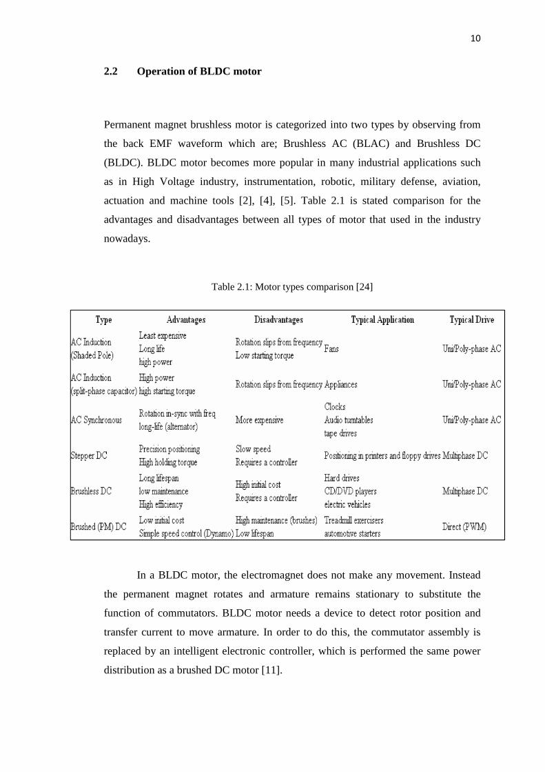
actuation and machine tools [2], [4], [5]. Table 2.1 is stated comparison for the
advantages and disadvantages between all types of motor that used in the industry
nowadays.
Table 2.1: Motor types comparison [24]
In a BLDC motor, the electromagnet does not make any movement. Instead
the permanent magnet rotates and armature remains stationary to substitute the
function of commutators. BLDC motor needs a device to detect rotor position and
transfer current to move armature. In order to do this, the commutator assembly is
replaced by an intelligent electronic controller, which is performed the same power
distribution as a brushed DC motor [11].
11
2.2.1 BLDC Motor Construction and Operating Principles
According to the research that had done by Ramesh et al. (2011), BLDC motor has
two main types which are trapezoidal and sinusoidal type. In the trapezoidal motor,
back EMF induced in the stator windings will has a trapezoidal shape and the phase
must be supplied with quasi-square current for ripple free torque operation.
Sinusoidal type has a sinusoidal shaped back EMF and required sinusoidal phase
current for ripple free torque operation. The sinusoidal motor needs a high resolution
position sensor because the rotor position needs to be checked at the time interval for
optimal operation. Other than that, the sinusoidal motor also required more complex
hardware and software. The BLDC motor works by switching the DC power supply
to the stator phase windings of the motor by using power devices while the rotor
position is used to determine the switching sequence.
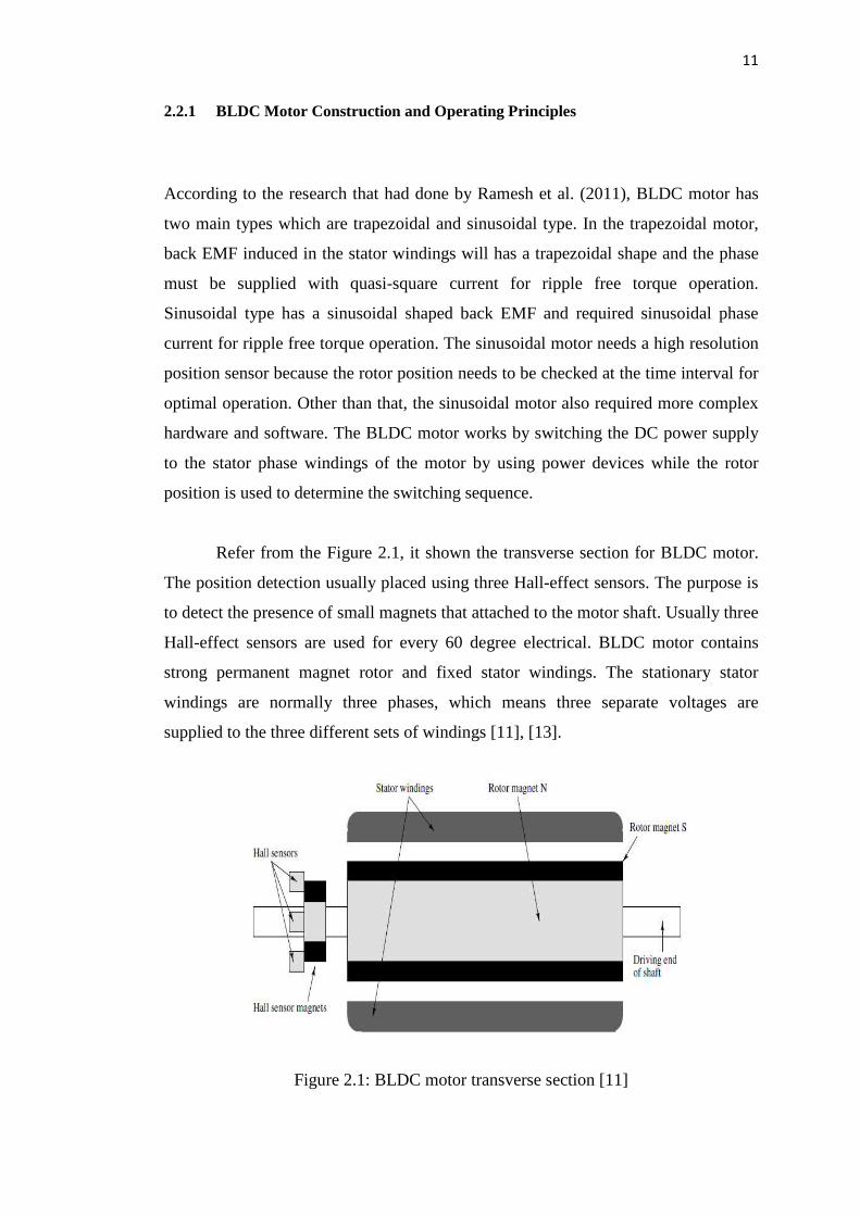
Refer from the Figure 2.1, it shown the transverse section for BLDC motor.
The position detection usually placed using three Hall-effect sensors. The purpose is
to detect the presence of small magnets that attached to the motor shaft. Usually three
Hall-effect sensors are used for every 60 degree electrical. BLDC motor contains
strong permanent magnet rotor and fixed stator windings. The stationary stator
windings are normally three phases, which means three separate voltages are
supplied to the three different sets of windings [11], [13].
Figure 2.1: BLDC motor transverse section [11]
12
To replace the function of commutators and brushes, the BLDC motor
requires an inverter and a position sensor that detects rotor position for proper
commutation of current. The rotation of the BLDC motor is based on the feedback of
rotor position which is obtained from the hall sensors. BLDC motor usually uses
three hall sensors for determining the commutation sequence. In BLDC motor the
power losses are in the stator where heat can be easily transferred through the frame
or cooling systems are used in large machines. BLDC motors have many advantages
over DC motors and induction motors. Some of the advantages are better speed
versus torque characteristics, high dynamic response, high efficiency, long operating
life, noiseless operation and has higher speed ranges [13], [18], [19].
From the previous study and literature that been reviewed, there is two
magnetic fields interact each other which result in movement. In brushless DC
motor, the permanent magnet stator set up the first magnetic field hence the rotor
winding produce the second field. When these two magnetic fields interact each
other will result in rotation. The two fields try to align each other however the
commutator continuously switches power from winding to winding which will
maintain the two magnetic fields at a 90 degree relationship. When a BLDC motor
rotates, each winding generates a voltage known as back electromotive force or back
EMF, which opposes the main voltage supplied to the windings according to Lenz’s
Law. Back EMF depends on the three factors; the angular velocity of the rotor,
magnetic field that is generated by rotor magnets and number of turns in the stator
windings [22].
The commutation phase sequence is like AB-AC-BC-BA-CA-CB, where A,
B, C are stand for three phases. Each conducting stage is called as one step.
Therefore, only two phases conduct current at any time, leaving the third phase
floating. In order to produce the maximum torque, the inverter should be
commutated every 60 degree, so current is in phase with the back EMF. The BLDC
motor can be controlled either by sensor or sensorless mode. The sensorless mode
commonly used due to the sensing part and sensorless control are higher requirement
for control algorithm and more complicated to design the electronic parts [22], [26],
[27].
CHAPTER 3
METHODOLOGY
3.1 Introduction
This chapter is discussed the planning of the research methodology that will be
adopted in achieving the objectives of the study. The purpose of this study is to
develop the dynamic model of BLDC motor and apply two types of controller
namely Proportional-Integral (PI) and Fuzzy Logic Controller (FLC) to control the
output response. The performance of the designed fuzzy and classical PI speed
controllers for BLDC motor is compared and investigated. The researches have been
designed and implemented after gathering all information from internet and journals.

13
2.2.2 Mathematical Equations of BLDC Motor
Figure 2.2 shows a DC motor equivalent model where Va= armature voltage (V), Ra=
armature resistance (Ω), La= armature inductance (H), Tm= motor torque (N-m), θ= angular
position of rotor shaft (rad), Jm= motor inertia (Kg-m2), Bm= viscous friction coeeficient
(Nm-s/ rad), KM= torque constant (N-m/ A) and Kb= back EMF constant (Vs/ rad). Based on
the DC motor model shown in Figure 2.2, the equations of the BLDC motor can be derived
as:
Figure 2.2: DC motor model [14]
By using the Kirchoff’s Voltage Law (KVL);
0)()( =+∂
∂++− tEbt
IaLRtVa (2.1)
By taking the Laplace Transform, equation (2.2) can be expressed in term of s as;
0)()()()( =+++− sEbssLIasRIasVa (2.2)
The motor torque, TM is related to the armature current, Ia by a constant coefficient of KM;
)()( sKmIasTm = (2.3)
The back electromotive force (back EMF) is relative to angular velocity, mω by;
tKKEb m
Bmb ∂∂
==θω (2.4)

14
Substitute equation (2.4) into equation (2.2), so;
0)()()( =∂
∂+++−
tKssLIasRIasVa m
B
θ (2.5)
0)()()()( =+++− sSKssLIasRIasVa mB θ (2.6)
By using Newton’s Second Law;
tBm
tJmTm mm
∂∂
+∂
∂=
θθ2
(2.7)
Then, again substitute equation (2.3) into equation (2.7) to obtain;
tBm
tJmsKmIa mm
∂∂
+∂
∂=
θθ2
)( (2.8)
Again, by taking the Laplace Transform, equation (2.8) can be expressed in term of s as;
)()()( 2 sBmSsJmSsKmIa mm θθ += (2.9)
From equation (2.9), )(sIa can be expressed as;
[ ]Km
BmJmssSsIa m +
=)(
)(θ
(2.10)
Substitute equation (2.10) into equation (2.6) to obtain;
[ ][ ]Km
KmKbRasLaBmJmssSsVa m +++
=)(
)(θ
(2.11)
Finally, the transfer functions of the BLDC motor can be obtained where the actual output can be identified by the position of θm(s) while the voltage of Va(s) can be as desired input. The overall transfer function of the BLDC motor is;
[ ][ ] KmKbRasLaBmJmss
Km
sVa
sm
+++=
)(
)(θ (2.12)
The constant values of input voltage (Va), torque constant factor (Km), motor inertia
(Jm), damping ratio (Bm), resistance (Ra) and the inductance (La) for the BLDC motor must
be known before simulating the BLDC motor model in MATLAB. An electrical and
mechanical time constants of the motor plays an important role whenever the load is rapidly
accelerated and decelerated frequently. The mechanical time constant in these motors are
reduced by reducing the inertia of the rotor.
15
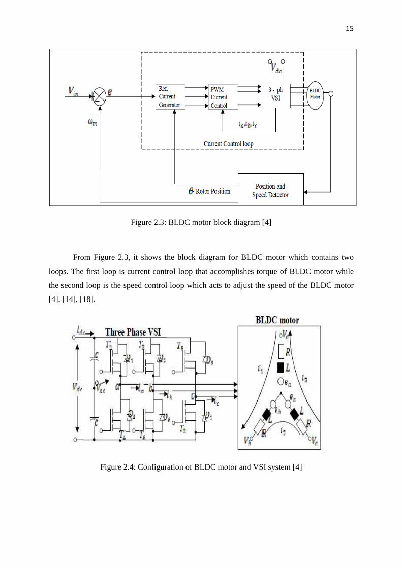
Figure 2.3: BLDC motor block diagram [4]
From Figure 2.3, it shows the block diagram for BLDC motor which contains two
loops. The first loop is current control loop that accomplishes torque of BLDC motor while
the second loop is the speed control loop which acts to adjust the speed of the BLDC motor
[4], [14], [18].
Figure 2.4: Configuration of BLDC motor and VSI system [4]

16
Based to the research done by Tan et al. (2011), due to the mathematical modeling for
BLDC motor, the design of the BLDC motor involves in complex process such as modeling,
device of control scheme, simulation and parameter tuning. The trapezoidal back EMF is
modeled as a function of rotor position so that the rotor position can be calculated according
to the operation speed. The back electromotive forces are expressed as a function of rotor
position (Ɵ). The equation can be derived as below:
( )( )( )
( )Rb
c
b
a
c
b
a
KE
f
f
f
E
e
e
e
ωθθθ
=
=
, (2.13)
Where bK is referred as back EMF constant,( )θaf , ( )θbf and ( )θcf are function of rotor
position while be and ce are trapezoidal of back EMF.
( )( )
( )
+
−−
−+
=
c
b
a
c
b
a
c
b
a
c
b
a
e
e
e
i
i
i
dt
d
ML
ML
ML
i
i
i
R
R
R
V
V
V
00
00
00
00
00
00
(2.14)
The motion equation is:
( )RLEm BTT
J
p
dt
Dω
ω −−
=2
(2.15)
The trapezoidal shape function with limit values between +1 and -1
( )
( ) ( )
( )
( )
≤<≤<≤<
≤<
−−
+−
≤<
=
πθππθπ
πθππθπ
θπ
θπ
πθθπ
θ
26/11
6/116/7
6/76/5
6/56/
12/6
1
6/6
16/0/6
af (2.16)

17
The expression of electromagnetic torque:-
Te = ke ( fa (θ) ia + fa (θ) ib + fc (θ) ic ) (2.17)
Speed and torque characteristics of BLDC motor:
[ ]∫ −++= dtTTTTJ
PLcbam )(
2ω (2.18)
The error and change in error:
e1 [n] = wref [n]– wr [n] (2.19)
e2 [n] = e1 [n] – e1 [n-1] (2.20)
18
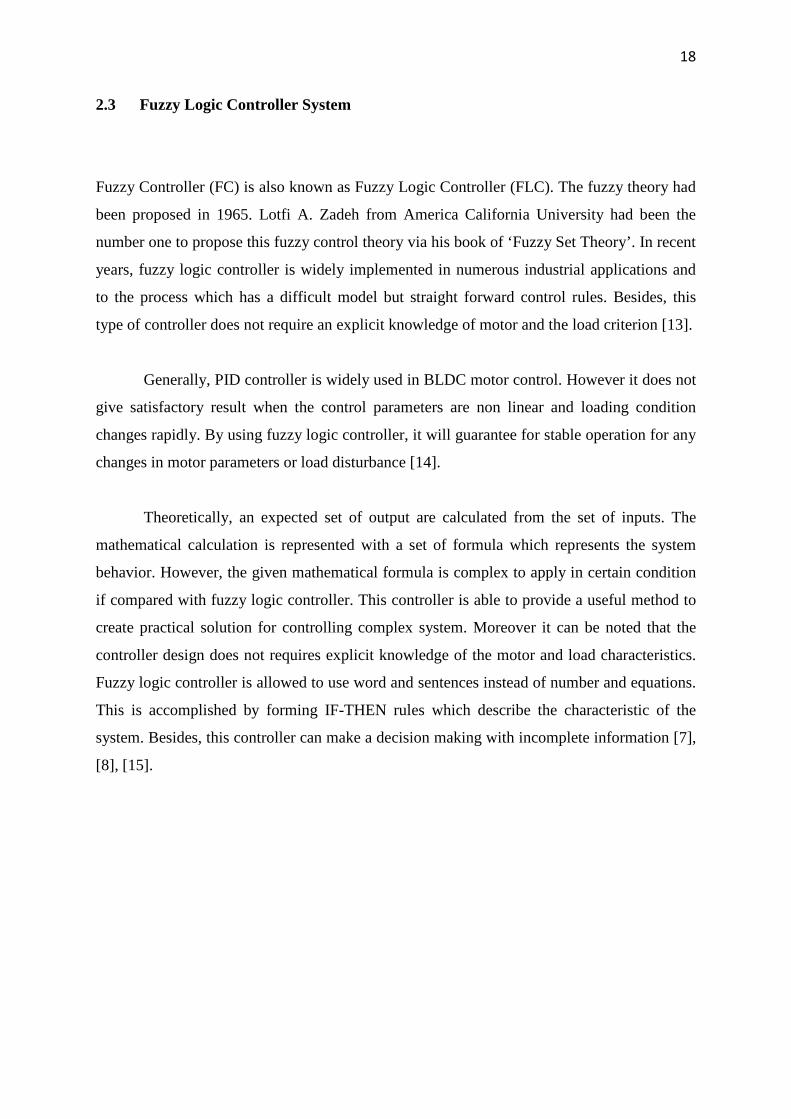
2.3 Fuzzy Logic Controller System
Fuzzy Controller (FC) is also known as Fuzzy Logic Controller (FLC). The fuzzy theory had
been proposed in 1965. Lotfi A. Zadeh from America California University had been the
number one to propose this fuzzy control theory via his book of ‘Fuzzy Set Theory’. In recent
years, fuzzy logic controller is widely implemented in numerous industrial applications and
to the process which has a difficult model but straight forward control rules. Besides, this
type of controller does not require an explicit knowledge of motor and the load criterion [13].
Generally, PID controller is widely used in BLDC motor control. However it does not
give satisfactory result when the control parameters are non linear and loading condition
changes rapidly. By using fuzzy logic controller, it will guarantee for stable operation for any
changes in motor parameters or load disturbance [14].
Theoretically, an expected set of output are calculated from the set of inputs. The
mathematical calculation is represented with a set of formula which represents the system
behavior. However, the given mathematical formula is complex to apply in certain condition
if compared with fuzzy logic controller. This controller is able to provide a useful method to
create practical solution for controlling complex system. Moreover it can be noted that the
controller design does not requires explicit knowledge of the motor and load characteristics.
Fuzzy logic controller is allowed to use word and sentences instead of number and equations.
This is accomplished by forming IF-THEN rules which describe the characteristic of the
system. Besides, this controller can make a decision making with incomplete information [7],
[8], [15].

19
Figure 2.5: Fuzzy logic controller block diagram [12]
Figure 2.6: Membership function of fuzzy controller [2]
From Figure 2.5, it shows fuzzy logic controller in a closed loop system. The FLC
block diagram has two input values (e1, e2) and one defuzzify output (u) as illustrated in
Figure 2.6. Both input variables are quantized into 3, 5 and 7 membership functions which
are Negative (N), Negative Small (NS), Negative Medium (NM), Negative Big (NB), Zero
(Z), Positive (P), Positive Small (PS), Positive Medium (PM) and Positive Big (PB). There
are four main stages in this controller which are fuzzification, rule base, inference engine and
20
defuzzification block. In the fuzzification process, the set of input data are compiled and
converted into fuzzy set by using fuzzy linguistic variables and membership functions. After
fuzzification process, it will goes to the next step named as fuzzy inference or inference
engine. In this step, output value of the fuzzy logic controller is determined by using a rule
base of [2], [11], [25] ;
IF (first condition) AND (second condition) THEN (conclusion)
For example;
If e1 is NB and e2 is NB Then u is PB,
If e1 is NB and e2 is NM Then u is PB,
If e1 is NB and e2 is NS Then u is PM,
If e1 is NB and e2 is Z Then u is PM,
………………………………………..
and continuously for all inputs.
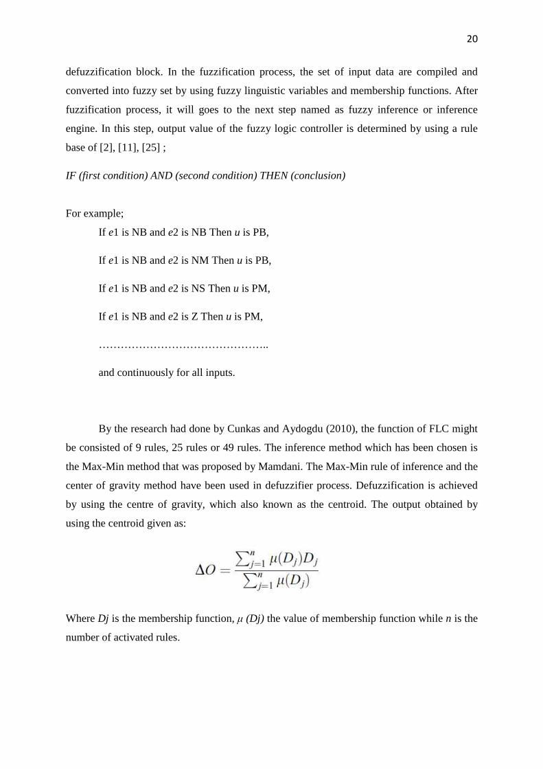
By the research had done by Cunkas and Aydogdu (2010), the function of FLC might
be consisted of 9 rules, 25 rules or 49 rules. The inference method which has been chosen is
the Max-Min method that was proposed by Mamdani. The Max-Min rule of inference and the
center of gravity method have been used in defuzzifier process. Defuzzification is achieved
by using the centre of gravity, which also known as the centroid. The output obtained by
using the centroid given as:
Where Dj is the membership function, µ (Dj) the value of membership function while n is the
number of activated rules.
21
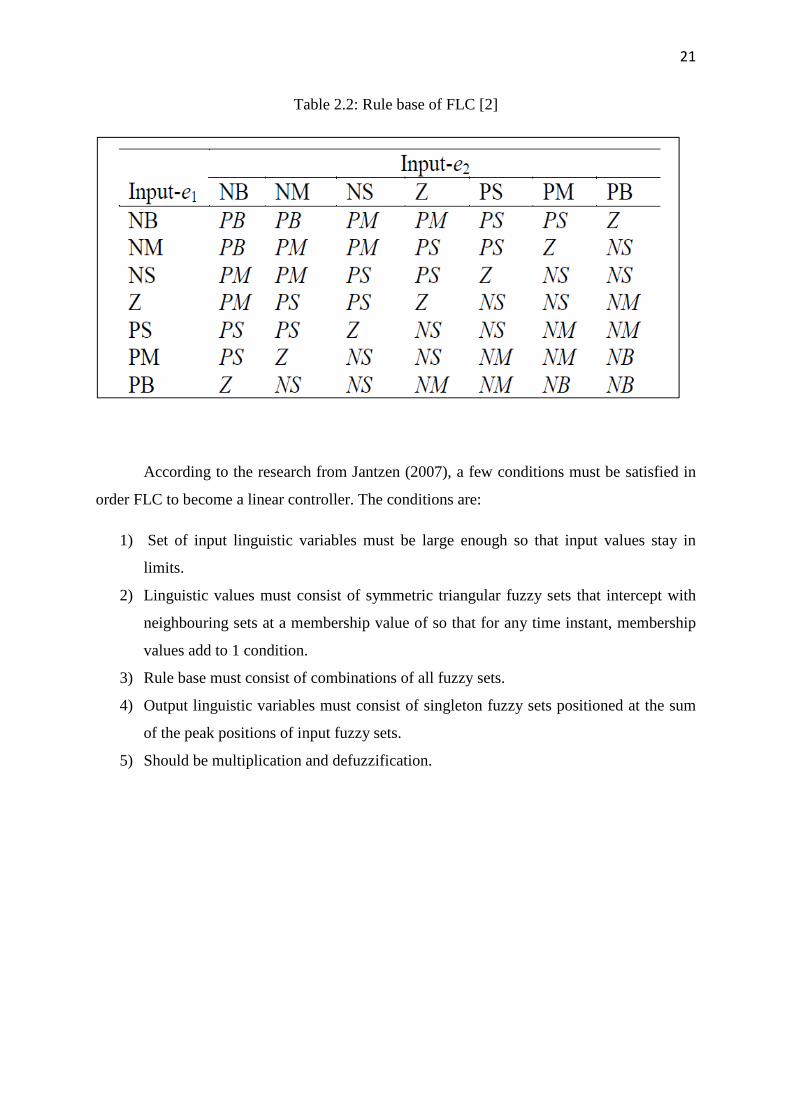
Table 2.2: Rule base of FLC [2]
According to the research from Jantzen (2007), a few conditions must be satisfied in
order FLC to become a linear controller. The conditions are:
1) Set of input linguistic variables must be large enough so that input values stay in
limits.
2) Linguistic values must consist of symmetric triangular fuzzy sets that intercept with
neighbouring sets at a membership value of so that for any time instant, membership
values add to 1 condition.
3) Rule base must consist of combinations of all fuzzy sets.
4) Output linguistic variables must consist of singleton fuzzy sets positioned at the sum
of the peak positions of input fuzzy sets.
5) Should be multiplication and defuzzification.

22
2.4 PID Controller Systems
PID controller is a simple three term controller. The letter of P stands for Proportional, I is
stands for Integral and D is referred as Derivative. This controller has been used for several
decades in industries for process control application. The reason for PID wide popularity lies
in the simplicity of design especially to control linear system and has a good performance
including low percentage overshoot and small settling time for slow process plants. A PID
controller will correct the error between the actual output and the desired input by calculating
and give an output of correction that will adjust the process accordingly [1], [20], [23].
Figure 2.7: Schematic model of PID controller [20]
Figure 2.7 is referred as the schematic model of PID controller. In the above figure,
control signal u (t) is a linear combination of error e (t), its integral and derivative where TI is
referred as an integral time while the derivative time is notes as TD. The control u from the
controller to the plant is equal to the Proportional gain (KP) times with the magnitude of the
error plus the Integral gain (KI) times the integral of the error plus the Derivative gain (KD)
times the derivative of the error that shown in equation (2.21) and (2.22) below, where KP =
Proportional gain, KI = Integral gain and KD = Derivative gain.

23
dt
tdeKdtteKteKtu DIP
)()()()( ∫ ++= (2.21)
++= ∫ dt
tdeTdtte
TteKtu D
IP
)()(
1)()( (2.22)
2.4.1 Tuning PID paramaters
PID controllers are tuned by using hand tuning or Ziegler-Nichols methods.
Normally, hand-tuning method is conducted by the experience control engineers according to
the rules which are stated in Table 2.3. However, these rules are not always valid. Besides, it
takes a long time to find the optimal values [20], [21].
Table 2.3: Rules for hand-tuning in PID controller [20]
Operation Rise Time, tr Peak Overshoot, Mp Stability
KP Faster Increases Decreases
TD Slower Decreases Increases
1/TI Faster Increases Decreases
Procedure for the hand-tuning method:
1) The derivative and integral actions are removed by setting TD and 1/TI equal to zero.
2) KP is tuned so that it will give the desired response except the final offset value from
the set point.
3) KP is slightly increased TD is adjusted to dampen the overshoot.
4) 1/TI is tuned such that final offset is removed.
5) The steps from no.3 are repeated until the value KP is reached as large as possible.

24
The second method to tune PID parameters is Ziegler-Nichols frequency response
method. This method will give poor results especially for the systems with a time lag much
greater than the dominating time constant. The damping is generally poor [21]. Table 2.4
shows the rules for the Zeigler-Nichols. This tuning method is used to find the controller
parameters of classical PID.
Table 2.4: Rules for Zeigler-Nichols [21]
Controller Proportional gain,
KP
Integral time,
TI
Derivative time,
TD
P 0.5 KU - -
PI 0.45 KU TU / 1.2 -
PID 0.6 KU TU / 2 TU / 8
Procedure for Zeigler-Nichols method:
1) KP is increased until the system response oscillates with constant amplitude and the
gain values of ultimate gain, KU value is recorded.
2) The oscillation period is calculated and records it as TU.
3) The parameters are tuned by using Table 2.4.

68
REFERENCES
1. Kandiban R., Arulmozhiyal R. (2012). Speed Control of BLDC motor using
Adaptive Fuzzy PID Controller. Procedia Engineering 38 (2012), 306-313.
2. Cunkas M., Aydogdu O. (2010). Realization of Fuzzy Logic Controlled
Brushless DC Motor Drives Using Matlab/ Simulink. Journal of
Mathematical and Computational Applications (2010), Vol 15, No. 2, pp
218-229.
3. Bhim S., Sanjeev S. (2009). State of the Art on Permanent Magnet Brushless
DC Motor Drivers. Journal of Power Electronics, Vol. 9, No. 1, January
2009.
4. Oyedepo J.A., Folanpomile A. (2011). Implementation of a Fuzzy Logic
Speed Controller for a Permanent Magnet Brushless DC Motor Drive System.
JORIND, Vol. 9, No. 2, December 2011.
5. Huazhang W. (2012). Design and Implementation of Brushless DC Motor
Drive and Control System. Procedia Engineering 29 (2012), 2219-2224.
6. Rubaai A., Marcel J., Castro S. and Abdul R.O. (2008). Design and
Implementation of Parallel Fuzzy PID Controller for High Performance
Brushless Motor Drives for Rapid Control Prototype. IEEE Transactions on
Industrial Applications 44(4), pp 1080-1087.
7. Senthil K. N., Senthil K.C. (2010). Design and Implementation of Adaptive
Fuzzy Controller for Speed Control of Brushless DC Motors. International
Journal of Computer Applications 2010, Vol 1, No. 27.
8. Bharathi Y.H., Rekha B.R., Baskar P., Parvathi C.S. and Kulkarni A.B.
(2008). Multi-input Fuzzy Logic Controller for Brushless DC Motor Drives.
Defense Science Journal, Vol. 58, No. 1, January 2008, pp 147-158.
9. Huang T.C., El-Sharkawi M.A. (1996). High Performance Speed and Position
Tracking of Induction Motors Using Multi-layer Fuzzy Control. IEEE
Transactions on Energy Conversion 11(2), pp 353-358.
69
10. Lee C.K., Pang W.H. (1994). A Brushless Motor Speed Control System
Using Fuzzy Rules. Proceedings of the Fifth IEEE International Conference
on Power Electronics and Variable Speed Drives, United Kingdom, October
16-28, 1994, pages 147-158.
11. Tan C.S., Baharuddin I., Siti Fatimah S., Fayzul M. (2011). Fuzzy Logic
Controller for BLDC Permanent Magnet Motor Drives. International Journal
of Electrical & Computer Sciences, Vol. 11, No. 2, April 2011.
12. Yuanxi W., Yali Y., Zhang G., Xiaoliang S. (2012). Fuzzy Auto-adjust PID
Controller Design of Brushless DC Motor. International Conference on
Medical Physics and Biomedical Engineering 33 (2012), pp 1533-1539.
13. Ramesh M.V., Amarnath J., Kamakshaiah S., Rao G.S. (2011). Speed
Control Of Brushless DC Motor by Using Fuzzy Logic PI Controller. ARPN
Journal of Engineering and Applied Sciences, Vol. 6, No. 9, September 2011.
14. Nader J.S.A. (2012). Design and Implementation of Fuzzy Position Control
System for Tracking Applications and Performance Comparison with
Conventional PID. IAES (Institute of Advanced Engineering and Science)
International Journal of Artificial Intelligence, Vol. 1, No. 1, March 2012,
pp. 31-44.
15. Jaydeep C., Ruchika S. (2013). Fuzzy Logic Based Method of Speed Control
of DC Motor. International Journal of Emerging Technology and Advanced
Engineering, Volume 3, Issue 4, April 2013.
16. Colak I., Bayindir R., and Bay O.F. (2003). Reactive Power Compensation
Using a Fuzzy Logic Controlled Synchronous Motor. Journal of Energy
Conversion and Management, Vol. 44, pp. 2189-2204, 2003.
17. Bay O.F. (1993). Fuzzy Control of a Field Orientation Controlled Induction
Motor. J Polytechnic, Vol. 3, pp. 1-9, 1993.
18. Kumar B.M., Ravi G., and Chakrabarti R. (2009). Sensorless Speed Control
of Brushless DC Motor with Fuzzy based Estimation. Iranian Journal of
Electrical and Computer Engineering, Vol. 8, No. 2, Summer Fall 2009.
19. Sakthivel G., Anandhi T.S., and Natarjan S.P. (2010). Real Time
Implementation of DSP based Fuzzy Logic Controller for Speed Control of
BLDC Motor. International Journal of Computer Applications, Vol. 10, No.
8, November 2010.

70
20. Manafeddin N., Onur B. (2010). DC Motor Position Control Using Fuzzy
Proportional-Derivative Controllers with Different Defuzzification Methods.
Turkish Journal of Fuzzy Systems, Vol. 1, No. 1, pp. 36-54, 2010.
21. Atef S.O.M. (2009). Proportional Integral and Derivative Control of
Brushless DC Motor. European Journal of Scientific Research, Vol. 35, No.
2, pp. 198-203, 2009.
22. Sivaprakasam P., Goutham G.R., John S.P., Sathishkumar A. (2012).
Mitigation of Torque for Brushless DC Motor: Modelling and Control.
International Journal of Scientific & Engineering Research, Vol. 3, Issue. 5,
May 2012.
23. Venu K.K., Ravi K.J., Sake P. (2009). Design and Implementation of
Fractional Order PID Controller for Aerofin Control System. World Congress
on Nature & Biologically Inspired Computing (NaBIC 2009).
24. Hubik V., Toman J., Singule V. (2010). BLDC Motor Control Design in
Matlab / Simulink. Zeszyty Problemowe – Maszyny Elektryczne, Nr 88 /
2010.
25. Sandeep K., Gurpreet B. (2012). Two Inputs Two Outputs Fuzzy Controller
System Design using MATLAB. International Journal of Advances in
Engineering, Science and Technology (IJAEST), Vol. 2, No. 3, August –
October 2010.
26. Lee B.K., Ehsani M. (2003). Advanced Simulation Model for Brushless DC
Motor Drives. Electric Power Components and Systems Research, Vol. 31,
pp. 841-868.
27. Shaamugasundram R., Zakariah K., Muhammaed, Yudaiah N. (2009). Digital
Implimentation of Fuzzy Logic Controller for Wide Range Speed Control of
Brushless DC Motor. IEEE International Conference on Vehicular
Electronics and Safety (ICVES), pp 119-229.
28. Tipsuwanporn V., Piyarat W., Tarasantisuk C.(2002). Identification and
Control of Brushless DC Motor Using On-Line Trained Artificial Neural
Networks. Power Conversion Conference, pp 1290-1299.
29. Jose C.G., Ernesto V.S., and Jaime G.G. (2010). Position and Speed Control
of Brushless DC Motors Using Sensorless Techniques and Application
Trends. Sensors Journal, pp 6901-6947.
71
30. Sivakotiah S., and Rekha J. (2011). Speed Control of Brushless DC Motor on
Resonant Pole Inverter Using Fuzzy Logic Controller. International Journal
of Engineering Science and Technology (IJEST), Vol. 3, No. 10, October
2011.
31. Halvaei A. N., Vahedi A., Moghbelli H. (2010). Speed Control of a Brushless
DC Motor Drive via Adaptive Neuro-Fuzzy Controller Based On Emotional
Learning Algorithm. pp 274-279.
32. Ram K.K., Choudhary G.K., Chitranjan K. (2011). Speed Control of
Separately Excited DC Motor using Fuzzy Technique. International Journal
on Electrical and Power Engineering, Vol. 2, No. 03, November 2011.
33. Metin D. (2011). Off-Line Tuning of a PI Speed Controller for a Permanent
Magnet Brushless DC Motor Using DSP. Journal on Energy Conversion and
Management, pp 264-273, 2011.
34. Khuntia S.R., Mohanty K.B., Panda S., and Ardil C. (2010). A Comparative
Study of P-I, I-P, Fuzzy and Neuro Fuzzy Controllers for Speed Control of
DC Motor Drive. International Journal of Electrical and Computer
Engineering, Vol. 5, No. 05, 2010.

72
VITA
The author was born in June 15, 1984 in Kemaman, Terengganu, Malaysia.
She went to Sekolah Rendah Sultan Ismail (SRSI) in Kemaman, Terengganu before
she continues her study in a secondary school at Sekolah Menengah Sains Sultan
Mahmud (SESMA) in Kuala Terengganu. Then, early 2002, she continues her study
in Matriculation Program at Pusat Asasi Sains Universiti Malaya (PASUM) in Kuala
Lumpur. One year later, she pursued her degree at Universiti Tenaga Nasional
(UNITEN) which is located between Putrajaya and Bangi. She is graduated with the
B.Eng (Hons) in Electrical and Electronic Engineering in August, 2008. In January
2009, she becomes a lecturer for Diploma Program at Kolej Poly-Tech MARA
(KPTM) in Kuantan branch. She was admitted to Master Program in Electrical
Engineering in early January 2011.

73
APPENDIX A
BLDC Motor system without controller
74
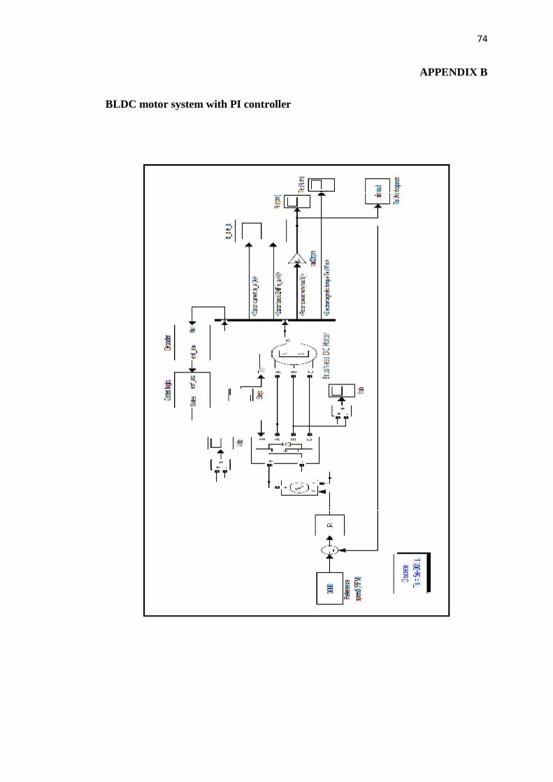
APPENDIX B
BLDC motor system with PI controller

75
APPENDIX C
BLDC motor with Fuzzy logic controller in MATLAB/Simulink