simulation of thermodynamics and flow processes at nano scales
DESCRIPTION
Simulation of Thermodynamics and Flow Processes at Nano Scales. Suresh K. Aggarwal , Mechanical and Industrial Engineering. Use of Monte Carlo and Molecular Dynamics methods to investigate thermodynamics and flow processes at nanoscales - PowerPoint PPT PresentationTRANSCRIPT
Problem Statement and Motivation
Key Achievements and Future GoalsTechnical Approach
Simulation of Thermodynamics and Flow Processes at Nano Scales
Suresh K. Aggarwal, Mechanical and Industrial Engineering
• Use of Monte Carlo and Molecular Dynamics methods to investigate thermodynamics and flow processes at nanoscales
• Dynamics of droplet collision and interfacial processes
• Interaction of a nanodroplet with carbon nanotube
• Solid-liquid Interactions and Nanolubrication
• Molecular Dynamics Simulation of Droplet Evaporation, Int. J. of Heat & Mass Transfer, 46, pp. 3179-3188, 2003.
• Molecular Dynamics Simulations of Droplet Collision. M.S. Thesis, K. Shukla, 2003.
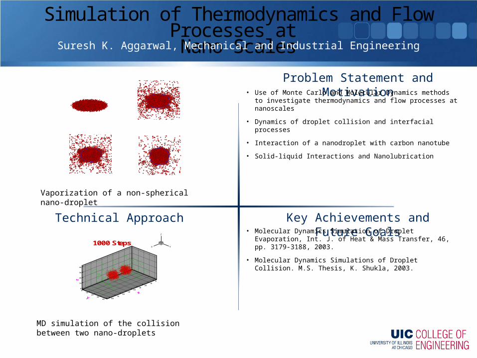
Vaporization of a non-spherical nano-droplet
0
10
20
30
40
z
010
2030
4050
6070
80
010
2030
40
X Y
Z
1000 Steps
MD simulation of the collision between two nano-droplets
Problem Statement and Motivation
Key Achievements and Future GoalsTechnical Approach
Electrical Properties for Metallic NanowiresInvestigator: Carmen M. Lilley, Mechanical Engineering
Prime Grant Support: NSF
• Successful integration of nanosystems into microelectronics depends on stable material properties that are reliable for at least a 10 year lifecycle with over a trillion cycles of operation.
• Fundamental understanding of the physics of deformation and failure in nanometer scale capped or layered structures, where surfaces play a dominant role, does not exist. Prior work has mostly focused on monolithic nanometer scale materials.
• Preliminary results on measuring the presence of surface contaminants and their influence on electrical properties completed [1].
• In depth study on size and surface effects on electromigration for Cu and Au nanowires have been performed [2-4]
• Additionally, this work has been extended to studying electron surface scattering for single crystalline Ag nanowires.
• Identify surface contaminants present in as-synthesized nanowires according to metallic, organic, and mixed-materials classifications.
• Measure the electrical properties of as-synthesized nanowires and identify contamination effects on electrical properties with an accuracy of 5%.
• Measure the stability of electrical properties of nanowires under accelerated electrical testing and classified according to structure.
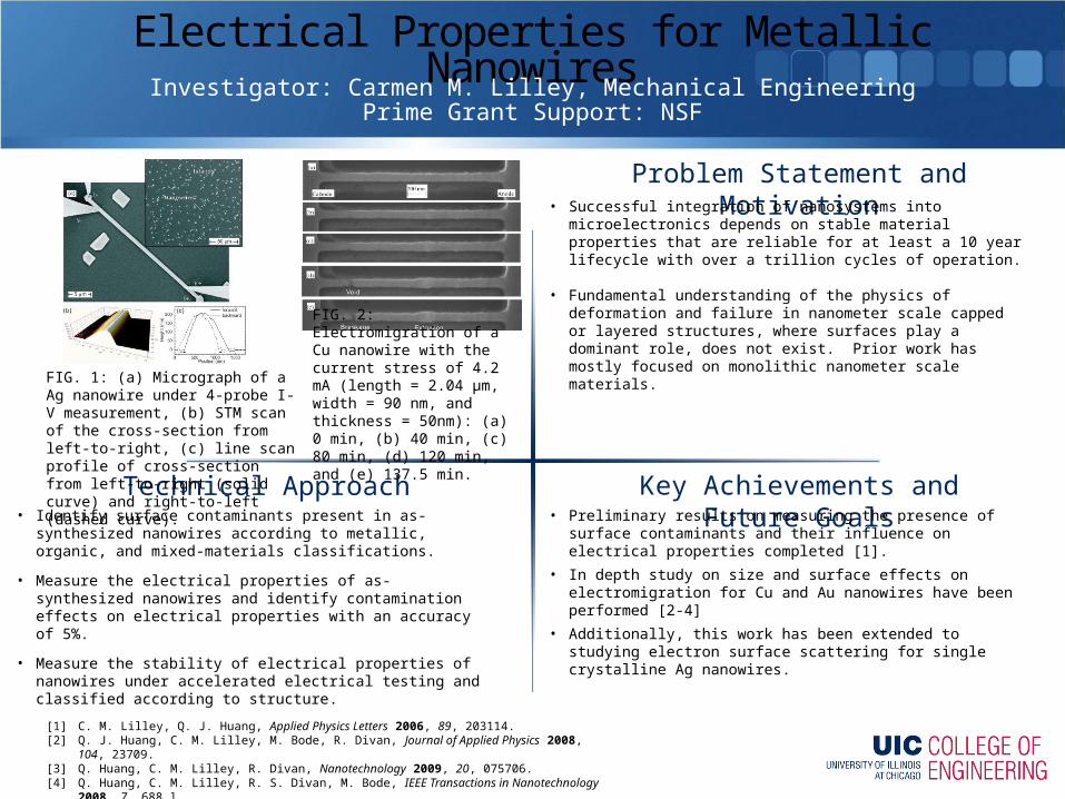
FIG. 1: (a) Micrograph of a Ag nanowire under 4-probe I-V measurement, (b) STM scan of the cross-section from left-to-right, (c) line scan profile of cross-section from left-to-right (solid curve) and right-to-left (dashed curve).
FIG. 2: Electromigration of a Cu nanowire with the current stress of 4.2 mA (length = 2.04 µm, width = 90 nm, and thickness = 50nm): (a) 0 min, (b) 40 min, (c) 80 min, (d) 120 min, and (e) 137.5 min.
[1] C. M. Lilley, Q. J. Huang, Applied Physics Letters 2006, 89, 203114. [2] Q. J. Huang, C. M. Lilley, M. Bode, R. Divan, Journal of Applied Physics 2008, 104, 23709.[3] Q. Huang, C. M. Lilley, R. Divan, Nanotechnology 2009, 20, 075706.[4] Q. Huang, C. M. Lilley, R. S. Divan, M. Bode, IEEE Transactions in Nanotechnology 2008, 7, 688.]
Problem Statement and Motivation
Key Achievements and Future GoalsTechnical Approach
Surface Effects on the Overall Young’s Modulus of FCC Metal Nanowires
Investigator: Carmen M. Lilley, Mechanical Engineering
• Surface effects, such as a surface elastic modulus and surface stress have been predicted for FCC NWs from atomistic simulations.
• Experimentally, elastic modulus measurements of FCC metal NWs have been found to vary widely. Some results indicate apparent size effects, other studies indicate no size effects.
• For Nanoelectromechanical Systems (NEMS), accurate elastic properties are necessary to design devices.
• Derived analytical solutions for NWs under static and dynamic bending. [1,2]
• Validated theory that surface stress and boundary conditions affect the apparent elastic modulus measured experimentally. [1,2]
• Proposed a surface effect factor as a qualitative parameter predict the influence of surface stress and geometry on the elastic behavior of static bending nanowires. [1,2]
• Extending the method to large deformation of nanowires for application to NEMS resonators. [3]
• Model the elastic bending behavior of face centered cubic (FCC) metals with continuum mechanics.
• Apply Young-Laplace Theory to study transverse load effects as a result of surface stress of nanowires (NWs) due to undercoordinated atoms at the surface.
• Study the influence of boundary conditions on the resultant bending mechanical behavior of nanowires.
• Test hypothesis that surface stress and boundary conditions affect the apparent elastic modulus of NWs.
Undeformed NW centerline
Deformed NW centerline
x
p(x)=Hv''
v
(a)
(b) (c)
O
y
z
y
zOθ
Left
Top
Right
Bottom
w
t D
t1
t1
SurfaceNote: Drawings are not to scale.
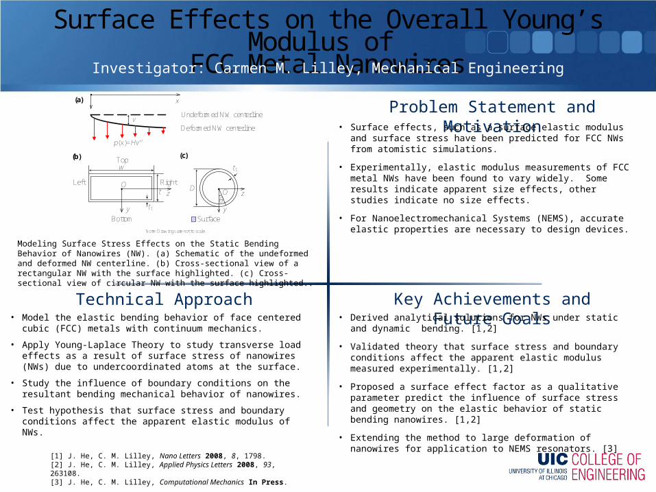
Modeling Surface Stress Effects on the Static Bending Behavior of Nanowires (NW). (a) Schematic of the undeformed and deformed NW centerline. (b) Cross-sectional view of a rectangular NW with the surface highlighted. (c) Cross-sectional view of circular NW with the surface highlighted..
[1] J. He, C. M. Lilley, Nano Letters 2008, 8, 1798.[2] J. He, C. M. Lilley, Applied Physics Letters 2008, 93, 263108.[3] J. He, C. M. Lilley, Computational Mechanics In Press.

Problem Statement and Motivation
Key Achievements and Future GoalsTechnical Approach
Low-Pressure Plasma Process for Nanoparticle CoatingInvestigators: Farzad Mashayek, MIE/UIC; Themis Matsoukas, ChE/Penn State
Prime Grant Support: NSF
Nanoparticles of various materials are building blocks and important constituents of ceramics and metal composites, pharmaceutical and food products, energy related products such as solid fuels and batteries, and electronics related products. The ability to manipulate the surface properties of nanoparticles through deposition of one or more materials can greatly enhance their applicability.
• The batch reactor is already operational and has been used to demonstrate the possibility of coating nanoparticles.
• A reaction model has been developed to predict the deposition rate on the nanoparticle surface.
• The possibility of using an external magnetic field to control the trapping of the particles has been investigated computationally.
• The experimental effort is now focused on the design of the “continuous” mode reactor.
• The computational effort is focused on development of a comprehensive code for simulation of the plasma reactor, nanoparticle dynamics, and surface deposition.
A low-pressure, non-equilibrium plasma process is developed using experimental and computational approaches. Two types of reactors are being considered. The first reactor operates in “batch” mode by trapping the nanoparticles in the plasma sheath. Agglomeration of the particles is prevented due to the negative charges on the particles. The second reactor is being designed to operate in a “continuous” mode where the rate of production may be significantly increased. This reactor will also provide a more uniform coating by keeping the nanoparticles outside the plasma sheath.
Nanolayer coating on a silica particle
Simulated flow of ions over a nanoparticle
Problem Statement and Motivation
Key Achievements and Future GoalsTechnical Approach
Carbon Nanopipes for Nanofluidic Devices Investigators: C. M. Megaridis, A. Yarin, Mechanical and Industrial Eng., UIC;
Y. Gogotsi, J.C. Bradley, Drexel Univ.; H. Bau, Univ. PennsylvaniaPrime Grant Support: National Science Foundation
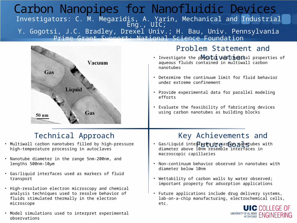
• Investigate the physical and chemical properties of aqueous fluids contained in multiwall carbon nanotubes
• Determine the continuum limit for fluid behavior under extreme confinement
• Provide experimental data for parallel modeling efforts
• Evaluate the feasibility of fabricating devices using carbon nanotubes as building blocks
• Gas/Liquid interfaces in carbon nanotubes with diameter above 10nm resemble interfaces in macroscopic capillaries
• Non-continuum behavior observed in nanotubes with diameter below 10nm
• Wettability of carbon walls by water observed; important property for adsorption applications
• Future applications include drug delivery systems, lab-on-a-chip manufacturing, electrochemical cells, etc.
• Multiwall carbon nanotubes filled by high-pressure high-temperature processing in autoclaves
• Nanotube diameter in the range 5nm-200nm, and lengths 500nm-10μm
• Gas/liquid interfaces used as markers of fluid transport
• High-resolution electron microscopy and chemical analysis techniques used to resolve behavior of fluids stimulated thermally in the electron microscope
• Model simulations used to interpret experimental observations
Problem Statement and Motivation
Key Achievements and Future GoalsTechnical Approach
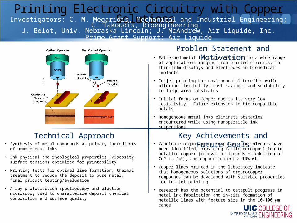
Printing Electronic Circuitry with Copper Solutions Investigators: C. M. Megaridis, Mechanical and Industrial Engineering; C. Takoudis, Bioengineering;
J. Belot, Univ. Nebraska-Lincoln; J. McAndrew, Air Liquide, Inc.Prime Grant Support: Air Liquide
• Patterned metal films are essential to a wide range of applications ranging from printed circuits, to thin-film displays and electrodes in biomedical implants
• Inkjet printing has environmental benefits while offering flexibility, cost savings, and scalability to large area substrates
• Initial focus on Copper due to its very low resistivity. Future extension to bio-compatible metals
• Homogeneous metal inks eliminate obstacles encountered while using nanoparticle ink suspensions
• Candidate organocopper compounds and solvents have been identified, providing facile decomposition to metallic copper (removal of ligands + reduction of Cu2+ to Cu0), and copper content > 10% wt.
• Copper lines printed in the laboratory indicate that homogeneous solutions of organocopper compounds can be developed with suitable properties for ink-jet printing
• Research has the potential to catapult progress in metal ink fabrication and in-situ formation of metallic lines with feature size in the 10-100 m range
• Synthesis of metal compounds as primary ingredients of homogeneous inks
• Ink physical and rheological properties (viscosity, surface tension) optimized for printability
• Printing tests for optimal line formation; thermal treatment to reduce the deposit to pure metal; final product testing/evaluation
• X-ray photoelectron spectroscopy and electron microscopy used to characterize deposit chemical composition and surface quality

Problem Statement and Motivation
Key Achievements and Future GoalsTechnical Approach
Coordinated Manipulation Methodology for Nanomanufacturing Investigator: Laxman Saggere, Mechanical and Industrial Engineering
Prime Grant Support: NSF
Motivation: Nanomanufacturing is critical for building new functional and useful products. Nanomanufacturing by an assembly-based approach promises to fill the void between the current “bottom-up” and “top-down” approaches and enable assembly of building blocks in future NEMS. However, despite recent advances, currently available tools and techniques for mechanical manipulation of micro/nano-scale objects lack dexterity to accomplish complex assembly of nano-scale objects. The success of assembly-based nanomanufacturing will depend on a micromanipulator tool with high-degree of dexterity beyond that provided by current simple cantilevers and parallel jaw grippers and tweezers.Objectives: To investigate the principles and fundamental issues in a novel manipulation methodology based on the coordinated action of multiple agile fingers at a chipscale to accomplish controlled contact manipulation tasks such as grasp, rotate, regrasp, move and position micro- and nano-scale objects in a defined 2D workspace.
Key Achievements: A novel micromanipulation system comprised of a multifingered micromanipulator chip integrated with piezo actuators and enclosed in a precision-machined custom housing has been developed. This micromanipulator system enables highly dexterous manipulations of micro-scale objects on the chip by coordinated action of the fingers when controlled in a close-loop by external user inputs supplied via a wireless gamming controller.
Future Goals: To achieve high precision coordinated manipulation of micro/nano-scale objects incorporating a more sophisticated position/force feedback and a fully programmed motion planning for assembly of the objects in the manipulator workspace.
The approach involves a novel chipscale micromanipulator comprised of four (or more) tiny compliant fingers, each of which can be independently actuated by integrated piezo actuators. By providing controlled actuation, the fingers can be guided to move in-plane and coordinate with each other to carry out controlled manipulation tasks such as grasp, rotate, move point-to-point and position micro- and nano-scale objects and perform assembly operations in a defined 2D workspace in the plane of the chip. The actuation, and thus, the motion of the micromanipulator fingers can be controlled by means of external user inputs via a gaming controller or a programmed software and visual feedback of locations and motions of the fingers/objects on a video monitor.
SEM of the micromanipulator chipIntegrated micromanipulator system
Experimental setup including user control inputs and visual feedback
A 20-m sphere gripped & moved by two fingers
A 20-m sphere rotated between two fingers
A micro-object gripped & moved by the fingers
A micro-object rotated between two fingers
Problem Statement and Motivation
Key Achievements and Future GoalsTechnical Approach
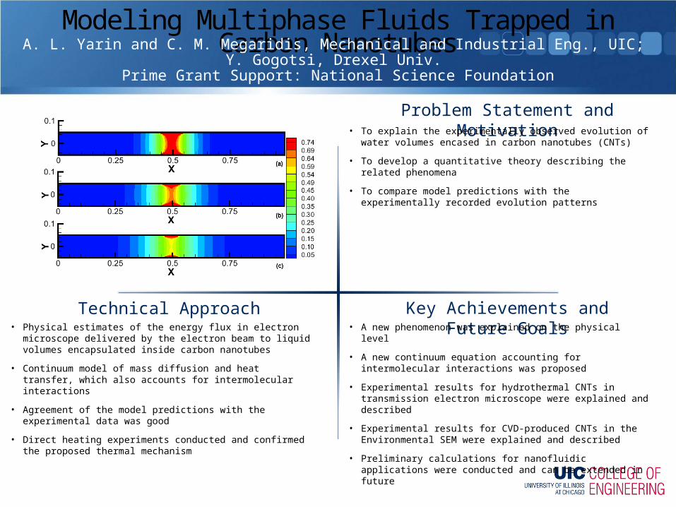
Modeling Multiphase Fluids Trapped in Carbon NanotubesA. L. Yarin and C. M. Megaridis, Mechanical and Industrial Eng., UIC;
Y. Gogotsi, Drexel Univ. Prime Grant Support: National Science Foundation
• To explain the experimentally observed evolution of water volumes encased in carbon nanotubes (CNTs)
• To develop a quantitative theory describing the related phenomena
• To compare model predictions with the experimentally recorded evolution patterns
• A new phenomenon was explained on the physical level
• A new continuum equation accounting for intermolecular interactions was proposed
• Experimental results for hydrothermal CNTs in transmission electron microscope were explained and described
• Experimental results for CVD-produced CNTs in the Environmental SEM were explained and described
• Preliminary calculations for nanofluidic applications were conducted and can be extended in future
• Physical estimates of the energy flux in electron microscope delivered by the electron beam to liquid volumes encapsulated inside carbon nanotubes
• Continuum model of mass diffusion and heat transfer, which also accounts for intermolecular interactions
• Agreement of the model predictions with the experimental data was good
• Direct heating experiments conducted and confirmed the proposed thermal mechanism
Problem Statement and Motivation
Key Achievements and Future GoalsTechnical Approach
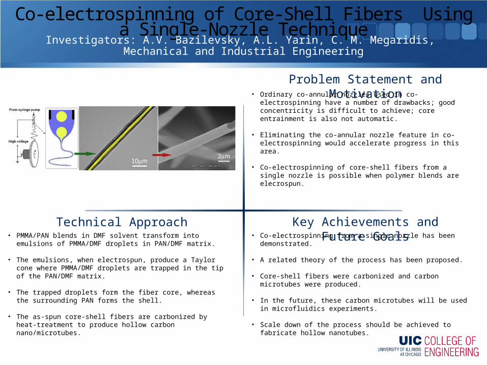
Co-electrospinning of Core-Shell Fibers Using a Single-Nozzle TechniqueInvestigators: A.V. Bazilevsky, A.L. Yarin, C. M. Megaridis,
Mechanical and Industrial Engineering
• Ordinary co-annular nozzles used in co-electrospinning have a number of drawbacks; good concentricity is difficult to achieve; core entrainment is also not automatic.
• Eliminating the co-annular nozzle feature in co-electrospinning would accelerate progress in this area.
• Co-electrospinning of core-shell fibers from a single nozzle is possible when polymer blends are elecrospun.
• Co-electrospinning from a single nozzle has been demonstrated.
• A related theory of the process has been proposed.
• Core-shell fibers were carbonized and carbon microtubes were produced.
• In the future, these carbon microtubes will be used in microfluidics experiments.
• Scale down of the process should be achieved to fabricate hollow nanotubes.
• PMMA/PAN blends in DMF solvent transform into emulsions of PMMA/DMF droplets in PAN/DMF matrix.
• The emulsions, when electrospun, produce a Taylor cone where PMMA/DMF droplets are trapped in the tip of the PAN/DMF matrix.
• The trapped droplets form the fiber core, whereas the surrounding PAN forms the shell.
• The as-spun core-shell fibers are carbonized by heat-treatment to produce hollow carbon nano/microtubes.
Problem Statement and Motivation
Key Achievements and Future GoalsTechnical Approach
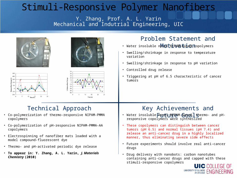
Stimuli-Responsive Polymer NanofibersY. Zhang, Prof. A. L. Yarin
Mechanical and Indutrial Engineering, UIC
• Water insoluble novel NIPAM-based copolymers
• Swelling/shrinkage in response to temperature variation
• Swelling/shrinkage in response to pH variation
• Controlled drug release
• Triggering at pH of 6.5 characteristic of cancer tumors
• Water insoluble novel NIPAM-based, thermo- and pH-responsive copolymers were synthesized
• These copolymers can distinguish between cancer tumors (pH 6.5) and normal tissues (pH 7.4) and release an anti-cancer drug in a highly localized manner, thus eliminating severe side effects
• Future experiments should involve real anti-cancer drugs
• Drug delivery with nanobots: carbon nanotubes containing anti-cancer drugs and capped with these stimuli-responsive copolymers
• Co-polymerization of thermo-responsive NIPAM-PMMA copolymers
• Co-polymerization of pH-responsive NIPAM-PMMA-AA copolymers
• Electrospinning of nanofiber mats loaded with a model compound-fluorescent dye
• Thermo- and pH-activated periodic dye release
• To appear in: Y. Zhang, A. L. Yarin, J. Materials Chemistry (2010)
Problem Statement and Motivation
Key Achievements and Future GoalsTechnical Approach
Giant Quasi-Slip in Flows in 500 nm Carbon NanotubesS. S. Ray, P. Chando, Prof. A. L. Yarin, Mechanical and Industrial Engineering
Prime Grant Support: NSF-NIRT CBET-0609062, NSF-EEC 0755115
• Laminar pressure-driven flows in carbon nanotubes
• Bi-layer flows of liquid and gas
• Nanofluidics
• Nanoreactors
• Drug delivery
• It was demonstrated experimentally and theoretically that bi-layer liquid/gas flows can result in an over-limiting flow regime
• In the over-limiting regime a higher flow rate of liquid can be achieved as compared to the case when the same liquid flows through the same tube subjected to the same pressure drop and occupies the whole bore. This means that it is possible to release more liquid than predicted by the Poiseuille law, even though in the bi-layer flow liquid does no occupy the whole cross-section
• The result effectively means a forced giant quasi-slip
• Nanofluidics, polymerization nanoreactors,drug delivery
• Electrospinning was used to produce polymer nanofibers, which served as templates for nanotubes
• Parallel arrays of thousands of nanofibers were embedded in polyacrylonitrile (PAN) strips
• Thermal treatment was used to carbonize PAN and eliminate the template nanofibers to make hollow channels
• Bi-layer n-decane/air flows were discharged in water, which allowed for measurements of the flow rate via observations of the liquid/liquid and liquid gas interfaces
• Published in S. S. Ray, P. Chando, A. L. Yarin, Nanotechnology 20, 095711 (2009)
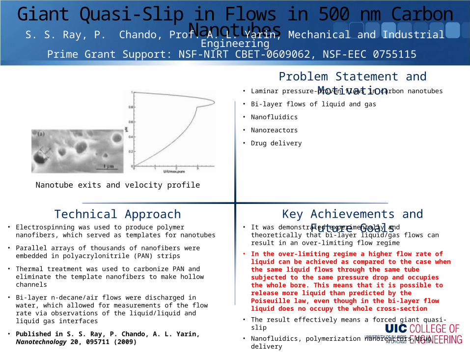
Nanotube exits and velocity profile