simulation using transaction level modeling
TRANSCRIPT

SIMULATION USING TRANSACTION LEVEL MODELING : IMPLEMENTATION FOR ARA™
MODULES
By
Arul Moondra
Thesis
Submitted to the Faculty of the
Graduate School of Vanderbilt University
in partial fulfillment of the requirements
for the degree of
MASTER OF SCIENCE
in
Computer Science
December, 2015
Nashville, Tennessee
Approved:
Janos Sztipanovits, Ph.D.
Janos Sallai, Ph.D.

ACKNOWLEDGMENTS
I would like to express my gratitude to my supervisor Professor Janos Sztipanovits for the useful comments,
remarks and engagement through the learning process of this master thesis. Furthermore, I would like to
thank Peter Volgyesi for introducing me to the topic as well for the support on the way. Also, I like to
thank Adam Nagel from Metamorph Inc and other team members who provided me help whenever needed
and guided me to the right direction. Finally, I would like to thank my parents for their continuous support
throughout the entire process and keeping me harmonious and helping me put my thesis together. I will be
grateful forever for your love.
ii

TABLE OF CONTENTS
Page
ACKNOWLEDGMENTS . . . . . . . . . . . . . . . . . . . . . . . . . . . . . . . . . . . . . . . ii
LIST OF TABLES . . . . . . . . . . . . . . . . . . . . . . . . . . . . . . . . . . . . . . . . . . . v
LIST OF FIGURES . . . . . . . . . . . . . . . . . . . . . . . . . . . . . . . . . . . . . . . . . . . vi
I Introduction . . . . . . . . . . . . . . . . . . . . . . . . . . . . . . . . . . . . . . . . . . . . 1
I.1 Google Ara . . . . . . . . . . . . . . . . . . . . . . . . . . . . . . . . . . . . . . . . . . . 2I.2 Organization of Thesis . . . . . . . . . . . . . . . . . . . . . . . . . . . . . . . . . . . . . 3
II SystemC and TLM: An overview . . . . . . . . . . . . . . . . . . . . . . . . . . . . . . . . . 4
II.1 SystemC Basics . . . . . . . . . . . . . . . . . . . . . . . . . . . . . . . . . . . . . . . . 4II.2 TLM-2.0 . . . . . . . . . . . . . . . . . . . . . . . . . . . . . . . . . . . . . . . . . . . . 5
II.2.1 Coding Styles . . . . . . . . . . . . . . . . . . . . . . . . . . . . . . . . . . . . . 7
III Google Project ARA™ and Greybus . . . . . . . . . . . . . . . . . . . . . . . . . . . . . . . 9
III.1 Unipro . . . . . . . . . . . . . . . . . . . . . . . . . . . . . . . . . . . . . . . . . . . . . 9III.2 Endoskeleton . . . . . . . . . . . . . . . . . . . . . . . . . . . . . . . . . . . . . . . . . . 11III.3 Greybus . . . . . . . . . . . . . . . . . . . . . . . . . . . . . . . . . . . . . . . . . . . . 12
III.3.1 Greybus Operation and Setup . . . . . . . . . . . . . . . . . . . . . . . . . . . . . 12III.3.2 Special Protocols . . . . . . . . . . . . . . . . . . . . . . . . . . . . . . . . . . . 15III.3.3 Device Class and Bridged PHY Protocol . . . . . . . . . . . . . . . . . . . . . . . 15
III.4 Summary of the ARA System . . . . . . . . . . . . . . . . . . . . . . . . . . . . . . . . . 15
IV Our Approach . . . . . . . . . . . . . . . . . . . . . . . . . . . . . . . . . . . . . . . . . . . 17
IV.1 Challenges . . . . . . . . . . . . . . . . . . . . . . . . . . . . . . . . . . . . . . . . . . . 17IV.2 System Model . . . . . . . . . . . . . . . . . . . . . . . . . . . . . . . . . . . . . . . . . 18
IV.2.1 Development Kit . . . . . . . . . . . . . . . . . . . . . . . . . . . . . . . . . . . 18IV.2.2 USB-Bridge . . . . . . . . . . . . . . . . . . . . . . . . . . . . . . . . . . . . . . 18IV.2.3 SystemC Application . . . . . . . . . . . . . . . . . . . . . . . . . . . . . . . . . 19IV.2.4 User Module . . . . . . . . . . . . . . . . . . . . . . . . . . . . . . . . . . . . . . 19
IV.3 Tasks performed by USB-Bridge . . . . . . . . . . . . . . . . . . . . . . . . . . . . . . . 19IV.3.1 Initial Setup . . . . . . . . . . . . . . . . . . . . . . . . . . . . . . . . . . . . . . 20IV.3.2 Insertion of Module . . . . . . . . . . . . . . . . . . . . . . . . . . . . . . . . . . 21IV.3.3 After the Insertion of Module . . . . . . . . . . . . . . . . . . . . . . . . . . . . . 22
IV.4 SystemC Application Design . . . . . . . . . . . . . . . . . . . . . . . . . . . . . . . . . 23IV.4.1 Block Diagram . . . . . . . . . . . . . . . . . . . . . . . . . . . . . . . . . . . . 23IV.4.2 TCP-Bridge . . . . . . . . . . . . . . . . . . . . . . . . . . . . . . . . . . . . . . 24IV.4.3 Router . . . . . . . . . . . . . . . . . . . . . . . . . . . . . . . . . . . . . . . . . 25IV.4.4 Control Handler . . . . . . . . . . . . . . . . . . . . . . . . . . . . . . . . . . . . 25IV.4.5 I2C handler . . . . . . . . . . . . . . . . . . . . . . . . . . . . . . . . . . . . . . 26
IV.4.5.1 I2C Transfer Operation . . . . . . . . . . . . . . . . . . . . . . . . . . . 27IV.4.6 I2C Controller . . . . . . . . . . . . . . . . . . . . . . . . . . . . . . . . . . . . . 28
iii

V Experiment and Results . . . . . . . . . . . . . . . . . . . . . . . . . . . . . . . . . . . . . . 30
V.1 Implementation Details . . . . . . . . . . . . . . . . . . . . . . . . . . . . . . . . . . . . 30V.2 The Compass Module . . . . . . . . . . . . . . . . . . . . . . . . . . . . . . . . . . . . . 31V.3 Communication Traces . . . . . . . . . . . . . . . . . . . . . . . . . . . . . . . . . . . . 32
VI Conclusion . . . . . . . . . . . . . . . . . . . . . . . . . . . . . . . . . . . . . . . . . . . . . 34
VI.1 Future Work . . . . . . . . . . . . . . . . . . . . . . . . . . . . . . . . . . . . . . . . . . 34
BIBLIOGRAPHY . . . . . . . . . . . . . . . . . . . . . . . . . . . . . . . . . . . . . . . . . . . 36
iv

LIST OF TABLES
Table Page
II.1 Generic Payload [4] . . . . . . . . . . . . . . . . . . . . . . . . . . . . . . . . . . . . . 6
III.1 Unipro Protocol Stack [1] . . . . . . . . . . . . . . . . . . . . . . . . . . . . . . . . . . 10
III.2 Greybus Header Format [13] . . . . . . . . . . . . . . . . . . . . . . . . . . . . . . . . 13
IV.1 SVC Operation Types [13] . . . . . . . . . . . . . . . . . . . . . . . . . . . . . . . . . . 21
IV.2 Manifest Descriptor [13] . . . . . . . . . . . . . . . . . . . . . . . . . . . . . . . . . . . 22
IV.3 Descriptor Types [13] . . . . . . . . . . . . . . . . . . . . . . . . . . . . . . . . . . . . 22
IV.4 Control Protocol Operations [13] . . . . . . . . . . . . . . . . . . . . . . . . . . . . . . 26
IV.6 I2C OP [13] . . . . . . . . . . . . . . . . . . . . . . . . . . . . . . . . . . . . . . . . . 27
IV.5 I2C protocol Operation Types [13] . . . . . . . . . . . . . . . . . . . . . . . . . . . . . 27
IV.7 I2C Protocol Transfer Request [13] . . . . . . . . . . . . . . . . . . . . . . . . . . . . . 28
v

LIST OF FIGURES
Figure Page
II.1 Key components in an OSCI TLM 2.0 model [5]. . . . . . . . . . . . . . . . . . . . . . . 6
II.2 TLM 2.0 Classes [12] . . . . . . . . . . . . . . . . . . . . . . . . . . . . . . . . . . . . 7
II.3 Speed vs. Coding Style [15] . . . . . . . . . . . . . . . . . . . . . . . . . . . . . . . . . 8
III.1 Example system architecture showing multiple UniPro devices connected via UniPro switches 10
III.2 EndoSkeleton [9] . . . . . . . . . . . . . . . . . . . . . . . . . . . . . . . . . . . . . . 11
III.3 Logical parts of a module . . . . . . . . . . . . . . . . . . . . . . . . . . . . . . . . . . 14
III.4 Network Stack over software and Hardware . . . . . . . . . . . . . . . . . . . . . . . . 16
IV.1 Top Level Abstract Model . . . . . . . . . . . . . . . . . . . . . . . . . . . . . . . . . 18
IV.2 Top-Level Model of SystemC Application . . . . . . . . . . . . . . . . . . . . . . . . . 24
V.1 Compass Module Flow Chart . . . . . . . . . . . . . . . . . . . . . . . . . . . . . . . . 31
V.2 I2C data transfer over a period of 20 ms . . . . . . . . . . . . . . . . . . . . . . . . . . . 32
V.3 Zoomed wave form of a single I2C transaction . . . . . . . . . . . . . . . . . . . . . . . 32
vi

CHAPTER I
Introduction
Current digital devices and applications are composed of deeply integrated hardware and software compo-
nents that form a complex web of interacting subsystems. In the past, hardware and software were indepen-
dently designed and then combined in the later design cycles. The hardware designs were modeled at Register
Transaction Level (RTL) level primarily using Verilog and VHDL and software was written in higher level
languages such C++/JAVA. This design methodology poses a number of disadvantages such as
1. The separation of hardware and software design flows severely increases the system integration effort
and makes it difficult and error-prone. For example, if the HW/SW interface definitions show deficits
or if the communication between hardware and software designers is insufficient, system integration
requires a lot of debugging and re-design.
2. The Later the defects are revealed, the more expensive is their removal. If they were injected in early
development phases, the designers often have to go back through the complete design cycle to detect
and mend them.
3. Besides the cost and quality issues, a major drawback of the separated development of hardware and
software is the issue of performance. The early HW/SW partitioning does not allow the evaluation of
different design alternatives, and thus sacrifices significant optimization potential.
To remove these shortcomings a new design methodology, HW/SW co-design methodology was proposed.
The central point is that hardware and software are developed together in an integrated system design process.
The design process starts with an abstract specification, but now, the HW/SW partitioning is not fixed
at the beginning. Instead, it is part of an iterative process, where different design alternatives are evaluated
and compared. As a consequence, it is possible to explore the whole design space and to find an optimal
HW/SW architecture. Furthermore, it allows an early analysis of HW/SW interfaces and thus reduces the
cost of integration and defect removal.
An essential component of co-design methods is HW/SW co-simulation, which is necessary to evaluate
and compare different design alternatives. In a HW/SW co-simulation, hardware and software parts of a
system are simulated together. Among these tools SystemC Initiative et al. [12], System-Verilog [3], and
SpecC [7] are the most popular.
SystemC, developed by Open System Initiative (OSCI), is a set of C++ libraries that provide an event-
driven kernel. SystemC is a system level design language that supports design space exploration and per-
1

formance evaluation efficiently throughout the whole design process even for large and complex HW/SW
systems, and thus, it is widely used in HW/SW co-design. It allows the description of both hardware and
software, and the designs are executable on different levels of abstraction. As a consequence, co-simulation,
i.e. the simultaneous execution of hardware and software, can be used for validation and verification through-
out the whole design process. SystemC also provides TLM-2.0 (Transaction Level Modeling) which provides
the capability to model hardware designs at a higher levels of abstraction concerning only with data trans-
fer, which facilitate in increased simulation speeds but sacrifice accuracy. The models in TLM-2.0 can have
incremental amount of timing information added that increases the accuracy of the model, but slows the sim-
ulation time. TLM 2.0 provides an advantage that one can model a system composed of modules at different
level of abstractions thus constructing a hybrid of abstracted and refined models. One module can be cycle
accurate while the other can be loosely timed. In this thesis, we discuss the simulation of a fairly complex
system known as Google Project ARA™ using SystemC. We discuss the use of TLM 2.0 and hybrid nature
of SystemC to provide real-time simulation of the system as well as SystemC ports that are cycle accurate
and can communicate with a generic SystemC module.
I.1 Google Ara
Project Ara™ [2] is a development effort to create a modular hardware ecosystem that aims at enabling users
to create a modular smartphone that is precisely tailored to their functional and aesthetic preferences. The
modular phone will have multi-functioning modules that can be hot swapped (swapped while the system is
running) from an endo-skeleton to allow the user to configure the phone according to their needs. These
modules will support complex hardware and software subsystems. To make this possible Google has intro-
duced a protocol called Greybus which works on top UniPro™ [1], which is high-speed interface technology
for interconnecting integrated circuits. It allows these modules to communicate with the main processor and
facilitates inter-module communication. An important characteristic of these modules subsystems is their
support for legacy protocols like UART, I2S, I2C, etc. This means that a module can have embedded chips
supporting legacy protocols and still communicate with the phone using a bridge irrespective of protocol
differences. This thesis aims to provide a framework that can simulate the ARA system in real time commu-
nicating to an actual hardware device to provide a user the means to verify and simulate an abstracted model
of the ARA module. This eliminates the use of expensive development boards provided by Google, in early
phases of development. While discussing the details of implementation, we also discuss the hybrid nature
of SystemC and particularly TLM 2.0 which allows us to jump between abstractions and refinements of the
model to strike a balance between accuracy of the model and speed of simulation.
2

I.2 Organization of Thesis
This thesis starts with outlining important aspects of SystemC with detailing some aspects that are used in this
thesis and are important to grasp the whole context. Then we delve into basics of Google Ara™ infrastructure,
which helps in discussing the actual implementation of the whole system. Then we discuss the challenges
of this thesis and the approach taken to design this framework. Finally, we take up an example module that
supports the I2C protocol and explain how it can be used to simulate a compass and communicate in real
time with an Android application. Finally in the results we analyze the system and discuss the benefits of
abstraction and refinement in a simulation system.
3

CHAPTER II
SystemC and TLM: An overview
Embedded systems developed today are composed of hardware and software specific to an application, which
are co-developed, usually on a tight schedule. Furthermore, some systems have strict real time performance
constraints. Such systems require thorough verification, which otherwise may lead to very expensive and
sometimes catastrophic failures. Software languages such as C++ and Java are not suited to model hardware
systems and are very different in philosophy to Verilog and VHDL, which were developed to support hard-
ware simulation. SystemC was developed to provide features that aid modeling of hardware, particularly the
parallelism of hardware in a mainstream programming language. It uses C++ and provides certain libraries
and Macros with an event driven software engine. This approach offers real productivity gains by letting
engineers co-designing both the hardware and software components as they would exist in a real system.
SystemC provides features for modeling hardware at clock accurate Register Transaction level (RTL)
similar to Verilog or VHDL but what makes it special is the concept of Transaction Level Modeling (TLM).
TLM is an abstract approach of modeling systems where the semantics of communication among modules
is separated from the semantics of the functional units that implement them. Communication mechanisms
are modeled as channels that are presented to SystemC modules via SystemC interface classes. In essence,
the designer is more concerned about what data is transferred rather than how it is transferred allowing
experimentation, for example, with different bus architectures.
II.1 SystemC Basics
This section provides high level details of SystemC and its basic constructs.1
• Modules: Modules are C++ classes that serve as the basic building blocks of a SystemC model. These
modules can contain other module providing a hierarchical system. They encapsulate hardware or
software description and communicate to other modules via ports.
• Ports and Interfaces: Ports are defined as objects inside a module which allow it to communicate with
other modules. SystemC provides a multitude of ports such as sc in<>,sc out <>sc fifo in<>etc.It
also allows user defined ports and interfaces.
• Processes: A process is a sequence of statements that define the behavior of a module. A module can
contain more than one processes that run concurrently. Processes contain an attribute which notifies
1It is assumed that the reader has experience with SystemC, and this only serves as a refresher
4

the simulation kernel that, a process is ready to be executed called sensitivity list. SystemC supports
both static and dynamic sensitive processes.
– SC METHOD: This process cannot be preempted. That means once it has started it will finish
off in the same time quantum and cannot call wait().
– SC THREAD: This process can be suspended in between by calling the wait() method, where
it waits for the next event or specified simulation time. Also, it is only executed once during
simulation and thus, generally needs an infinite loop to rerun.
The wait statement has very powerful consequence in SystemC. SystemC kernel is designed such that
the processes are run one by one, having pseudo-concurrency. This means a mechanism is required
so that processes can yield control to the kernel. This is done by calling wait(). After getting the
control, the kernel can increment the simulation time or run a process queued to be executed at the
same simulation time. Thus, a process that does not call wait() will not render its control to the kernel
and the simulation time will never increase. By the same logic, SC METHOD executes in the same
instance of simulation time.
• Channels: Channels are the communication medium or a generalized form of signals. SystemC pro-
vides multitude of predefined channels such as sc signal, sc fifo etc. It also allows user-defined chan-
nels. This feature is what differentiates SystemC from other hardware modeling languages since, mod-
eling abstraction at interface level allows great design and modeling flexibility [12] and [10].
II.2 TLM-2.0
On the simplest level, TLM-2.0 is a set of SystemC modules each providing one or more TLM sockets through
which the SystemC modules may communicate with each other. The behavior is provided by a number of
parallel threads whose execution is controlled by the SystemC kernel. Figure II.1 shows the key components
in a TLM 2.0 model. The communication between two modules is known as a transaction (hence the name),
and the data is called payload.
TLM-2.0 consists of a set of core-interfaces, the global quantum, the initiator and target sockets, the
generic payload, the base protocol, and the utilities. The TLM-2.0 core-interfaces consist of the blocking and
non-blocking transport interfaces, the direct memory interface (DMI), and the debug transport interface [4].
The primary purpose of SystemC and TLM-2.0 is interoperability and simulation speed. Speed here means
to execute an application software as fast as or faster than the hardware model. Interoperability means to
integrate models from different sources with a minimum engineering effort and without sacrificing simulation
speed. However, using SystemC alone is insufficient to ensure interoperability. SystemC offers too many
5

Figure II.1: Key components in an OSCI TLM 2.0 model [5].
degrees of freedom for writing a communication wrapper, thus the probability that two modules will talk to
each other off the shelf is minimal. Thus, the generic payload is introduced to support abstract modeling of
transaction (message passing) while maximizing interoperability. The TLM-2.0 classes are layered on top
of the SystemC class library as shown in Figure II.2. However it is entirely possible for anyone to write
their own payload and sockets to interface with them but, to maximize interoperability, it is recommended
that the TLM-2.0 core interfaces, sockets, generic payload and base protocol be used together in concert.
These classes are collectively known as the interoperability layer. In cases where the generic payload is
inappropriate, it is possible for the core interfaces and the initiator and target sockets, or the core interfaces
alone, to be used with an alternative transaction type.
Table II.1: Generic Payload [4]
Payload Description
Command Is this Read or Write?
Address Address of the memory
Data The pointer to the data
Response Response when the transaction
return signifying failure or success
6

Figure II.2: TLM 2.0 Classes [12]
The payload maybe defined by the programmer but, the generic payload provided by the TLM interface
(recommended for interoperability) is summarized in Table II.1. TLM 2.0 also recognizes the fact that there
can be a variety of use cases for TLM with abstraction levels based on different criteria such as function
abstraction, communication abstraction, granularity of time. The above-defined interfaces can be used to
design transaction level models using different coding styles that are appropriate for, but not locked to, the
various use cases [8] and [4].
II.2.1 Coding Styles
A coding style is a programming language idiom; that works well together. They do not define a specific
abstraction level. The coding styles can be broadly described as follows
• Untimed coding style, there is no notion of time and processes run as fast as possible to completion.
This method is not very useful in hardware modeling as any bus based system will need some notion
of time.
• Loosely Timed( LT) models are where each transaction has just two timing point, marking the start
and the end of the transaction. Simulation time is used, but to increase simulation speed the processes
are allowed to run ahead of the simulation time thus, they are temporally decoupled. Each process thus
7

Figure II.3: Speed vs. Coding Style [15]
has to keep its local time, and it is synchronized with the rest of the system when a wait is called, or it
has consumed its quantum.
• Approximately-timed (AT), each transaction has multiple timing points or phases. Processes run
in synchronization with SystemC simulation time. Delays defined onto the interaction between the
processes are implemented using timeouts (wait) or event notifications. As expected, this is slower
than the LT coding style but more accurate [4].
As mentioned earlier, TLM provides a two interfaces, Blocking and Non-Blocking for transfer of pay-
loads. Their definition is quite clear by their name, one providing blocking calls and the other non-blocking
calls. An LT (loosely timed) approach will most likely consist of Blocking calls and AT (approximately timed)
approach uses Non-Blocking calls. The coding style chosen greatly affects the simulation speed where Clock
Timed (CT) being the slowest used by VHDL and Verilog and Application Software (untimed) being the
fastest. SystemC acts as the bridge between the two with LT and AT. It gains speed and loses accuracy as it
moves from CT to Untimed. The speed of the simulation offered is also in between these two approaches as
presented by the Figure II.3.
8

CHAPTER III
Google Project ARA™ and Greybus
Project ARA™ is an initiative by Google™ to develop an open hardware platform for creating highly modular
smartphones. It allows the users to swap in and out multi-functioning ‘modules’ according to their need. This
not only provides ease of use to the users, but it also greatly reduces electronic waste and leads to longer
lifetime cycles for the handset.
Modules are the building blocks of Ara phone. They are the hardware equivalent of software applications.
They implement various phone functions such as a screen, camera, battery, etc. These modules connect on
an endoskeleton that provides with the locking mechanism as well as the connection ports for the module to
interact with other components of the phone.
These modules communicate via UniPro™ Protocol. On top of UniPro protocol, the Greybus proto-
col is built which provides semantics to the communication packets. The following sections describe the
aforementioned parts of the ARA phone in detail
III.1 Unipro
The architecture of the Project Ara requires an application layer specification, which can handle the insertion
and removal of modules dynamically, without constraint on time or location. It also requires that modules
can communicate and operate together with other modules that will be introduced at a later stage. Project Ara
uses the UniPro protocol for inter-module communication that fulfills these specifications. UniPro protocol
follows the OSI Layer and specifies how the communication shall occur up to the Application layer. It is
a high-speed interface technology for interconnecting integrated circuits in mobile and mobile-influenced
electronics. Its major features include gigabit/sec range data communication, low power operation, data
reliability and robustness (error checking and correction).
UniPro on an abstract level is analogous to LAN network. In such an environment, UniPro devices are
connected via links and messages are routed towards the destination using UniPro switches. The difference
being that UniPro is designed to connect chips within a terminal, as opposed to computers in a building.
Though a complete detail of UniPro is not required for following this thesis the Table III.1 describes the
different layers of UniPro.
9

Table III.1: Unipro Protocol Stack [1]
Layer # Layer Name Functionality Data Unit Name
LA Application Payload and Transaction Semantics Message
DME
Layer 4 Transport Ports, multiplexing and flow-control Segment
Layer 3 Network Addressing, Routing Packet
Layer 2 Data Link Single hop reliability, and priority based arbitration Frame
Layer 1.5 PHY adapter Physical layer abstraction and multi-lane support UniPro symbol
Layer 1 Physical Layer Signaling, clocking, line encoding, power modes PHY symbol
Each end of a connection in a UniPro communication environment is a UniPro Cport. A Cport is a
5-bit identifier, that is analogous to the port number in a TCP or a UDP connection, and serves as a sub-
address inside a UniPro device. The messages are addressed to a specific Cport of a specific UniPro device.
Each UniPro device has multiple Cports that are associated with different protocols as shown in Figure
III.1. Continuing with our previous analogy with TCP/UDP, as messages meant for different protocols are
forwarded to the respective port numbers (e.g. 8080 for HTTP), messages meant for different protocols are
forwarded to their respective Cport number [1].
Figure III.1: Example system architecture showing multiple UniPro devices connected via UniPro switches
The process of establishing a connection starts as soon as the AP (Application Processor) module learns
about the existence of a Cport in another module. This initial communication is handled by SVC (a special
unit explained later in this section). The AP Module allocates a Cport for its end of the connection, and
once the UniPro network switch is configured properly the connection can be used for data transfer (and in
10

particular, for operations).
III.2 Endoskeleton
The Ara Endoskeleton (or Endo) is the frame and backplane of the device, determining the size and layout
of the phone. Ara modules slide in and attach to the endos slots, which has connectors to electrically and
logically connect the modules together as shown in Figure III.2.
Figure III.2: EndoSkeleton [9]
An Endo, consists of the following elements:
• One UniPro switch, which distribute the UniPro messages throughout the network. This is the spine of
the endo.
• Exactly one Application Processor Module, hereafter referred to as the “AP” Module. The AP Module
is responsible for storing user data and executing applications. The Module that contains the AP is the
AP Module.
• One or more Interface blocks, these interface blacks are the connectors that allow the modules to
connect to the endo’s communication interface and other modules in the system.
• Exactly one Supervisory Controller, referred as “SVC”. The SVC oversees the ARA system, including
11

the system’s UniPro switches, its power bus, its wake/detect pins, and its RF bus. When a new module
is inserted only way of communication with the system is via this SVC.
The SVC has direct control over and responsibility for the endo, including detecting when modules
are present, configuring the UniPro switch, powering module Interfaces, and attaching and detaching
modules. The AP Module controls the endo through operations sent over the SVC connection, and the
SVC informs the AP Module about endo events (such as the presence of a new module, or notification
of changing power conditions). SVC also resides inside the spine of the endo.
• One or more Modules, which are physically inserted in the slots on the endo [1].
III.3 Greybus
Greybus communication defines how modules communicate over the UniPro network. Although UniPro
offers reliable transfer of data frames between interfaces, it is necessary to build a protocol that provides
semantics to the data being transferred. This allows the sender to confirm that the information or instructions
in the message had the expected result. For example, a request sent to a UniPro switch controller requesting
a reconfiguration of the routing table could fail, and proceeding as if a failure had not occurred in this case
leads to undefined behavior. Similarly, the AP Module likely needs to retrieve information from other mod-
ules. This requires that a message that is requesting information should be paired with a returned message
containing the information requested.
For this reason, Project Ara performs communication between the modules using Greybus Operations.
A Greybus Operation defines an activity (such as a data transfer) initiated in one module that is implemented
(or executed) by another. The particular activity performed is defined by the operation’s type. An operation
is implemented by a pair of messages one containing a request, and the other containing a response. Both
messages contain a simple header that includes the type of the operation and size of the message. In addition,
each operation has a unique ID, and both messages in an operation contain this value so that a response
can be associated with its matching request. Finally, all responses contain a byte in the message header to
communicate the status of the operation, either success or a reason for a failure [13]. The size and data
associated with a header are in Table III.2.
III.3.1 Greybus Operation and Setup
Greybus Operations are performed over Greybus Connections. A Greybus connection is a communication
path between two modules. As explained earlier, each end of a connection is a UniPro Cport. Each Cport in a
module is associated with a protocol. The protocol dictates the way the Cport interprets incoming operation
messages. In other words, the operation type in a request message has a different meaning for different
12

Table III.2: Greybus Header Format [13]
Offset Field Size Value Description0 Size 2 Number Size of the operation2 ID 2 ID Requestor supplied request identifier4 type 1 Number Type of Greybus Operation5 status 1 Number Operation result6 (pad) 2 0 Reserved(pad to 8 bytes)
protocols. Operation type 5 might mean“receive data” in one protocol while operation type 5 might mean
“go to sleep” in another protocol.
A module is a physical thing that a user may plug in. The Linux kernel which is the base of the Android
stack and thus the ARA phone does not see this. However, the kernel sees a logical thing that is called an
Interface. These are electrical points on the endo for the connection and have associated interface ids. The
endo is designed such that each module will have at least two interfaces or more. Inside these interfaces are
Cports. However, each interface needs a way to handle housekeeping, to describe itself to the descriptors and
for network management. Thus, every interface has Cport 0 which is reserved for this task.
Also, there is a need to group up Cports according to the functions they perform. This is because a module
can perform various functions. The kernel drivers control these functions. For example, a module can be a
wi-fi device and a battery. A battery needs a single Cport to talk to the AP however, the wi-fi will need
a multitude of Cports. Cports associated with the same functionality are grouped together. This group of
Cports associated with the same functionality is called a Bundle. When the Cports are grouped up according
to their function in bundles, the bundles can be bound to Linux drivers.
To summarize a module essentially consists of two or more interfaces each supporting a “Cport 0” and a
number of bundles. These bundles are a group of Cports that are related to a specific protocol, Figure III.3.
13

Figure III.3: Logical parts of a module
Now we can understand how the connections and are established and modules interact with each other in
a Greybus system.
Firstly, as soon as the module is inserted the SVC is notified, which in turn informs the AP module that, a
new module has been inserted. The AP gives instruction to the SVC to bind one of its Cports to Cport 0 of the
module inserted. Till now the AP has no information about the number of Cports and the type of protocols it
will use.
Next the AP Module asks for the Manifest from the module. The Manifest is a contiguous block of data
that includes a Manifest Header and a set of Descriptors. These descriptors define the number of Cports, the
protocols supported and the number of bundles, to the AP. When read, a Manifest is transferred completely.
This allows the Interface to be described to the AP Module in a single communication sequence, removing the
need for multiple back and fro messages during the enumeration phase. Details of the Manifest are discussed
in Chapter IV.
Reading the Manifest, the AP Module establishes the connections mentioned in the Manifest and also
directs the SVC to reconfigure the UniPro switch to direct the messages to the correct destination. The
switch is configured according to Interface id and Cport number. The connections use the associated Cport’s
advertised protocol.
The Greybus Operation mechanism forms a base layer on which other protocols are built. Protocols define
the format of request messages, their expected response data, and the effect of the request on the state in one
or both Modules. Users of a protocol can rely on the Greybus core getting the operation request message to
its intended target and transferring the operation status and any other data back. The process of establishing
a connection is concretely defined using two special protocols that are detailed in the next section.
14

III.3.2 Special Protocols
This section defines two Protocols, each of which serves a special purpose in a Greybus system.
The first is the Control Protocol. Every Interface provides a Cport (Cport 0) that uses the Control
Protocol. It is used by the SVC to do initial probes of interfaces at system power on. It is also used by the
AP Module to notify interfaces when connections are available for them to use. A Greybus connection is
established, whenever a control connection is used, but the interface is never notified that such a connection
exists. Only the SVC and AP Module can send control requests. Any other interface shall only send control
response messages, and such messages shall only be sent in reply to a request received at its control Cport.
The second is the SVC Protocol, which is used only between the SVC and the AP Module. The SVC
provides low-level control of the UniPro network. The SVC performs almost all of its activities under the
direction of the AP Module, and the SVC Protocol is used by the AP Module to exert this control. The SVC
also uses this protocol to notify the AP Module of events, such as the insertion or removal of a module [13].
III.3.3 Device Class and Bridged PHY Protocol
Greybus also defines a group of protocols that are primarily designed to provide a device abstraction for
functionality commonly found in mobile phones. These may include cameras that utilize MIPI CSI-3 [1],
vibrators, battery. These protocols are called Device Class Protocol. On the hardware level these devices
connect directly to the UniPro bus, however, devices without native UniPro will utilize a Bridge called GP-
Bridge to communicate over the UniPro network. The GPBridge converts common interfaces such as I2C,
USB and UART for transmission over the UniPro network to an AP Module. Any device that does not support
the Device Class Protocol should support the Bridged PHY Protocol which is a protocol whose purpose is
to support communication with Modules on the Greybus network that do not comply with an existing Device
Class Protocol.
III.4 Summary of the ARA System
The Figure III.4 presents the whole architecture of networking in Project ARA. The dotted line divides the
software and the hardware components of the system. The hardware side includes the UniPro controller,
UniPro switch and the Modules with the GPBridge. The software part consists of the Greybus system inside
a Linux kernel and an Android Stack. The software also includes the protocols defined earlier, the Device
Class and the Bridged PHY protocol.
On the hardware side, we have an AP Module, which interacts with a UniPro switch. The UniPro switch
can talk to the modules in two primary ways. By using native Unipro Bus or via a bridge called GPBridge
which converts UniPro messages to a legacy protocol such as I2C, UART, etc.
15

On the software side, we have the Greybus Subsystem, which resides over the UniPro protocol stack. The
Greybus lies inside the kernel of the Android stack. The Greybus system also talks to the modules in two
primary ways that are analogous to the two ways defined in the hardware side defined earlier. These are the
Device Class and the Bridged PHY protocols that allow direct communication or communication via a bridge
respectively. Thus, a module using a Device Class Protocol interacts directly with the UniPro Bus. However,
any device that is not Device Class conformant uses the Bridged PHY Protocol and connects to the UniPro
bus via the GPBridge.
Figure III.4: Network Stack over software and Hardware
16

CHAPTER IV
Our Approach
The primary aim of this framework is to provide the user, the capability to model and simulate the ARA
modules in real time. It also seeks to allow the user to attach Android applications to the system so that the
system can be simulated as it would exist in the real world. In developing such a system there were many
challenges. This chapter first discusses the challenges faced. Then it describes the System Model which is
divided into four parts and our approach to counter these challenges with each part in detail.
IV.1 Challenges
There we many challenges to this framework. The following section outlines the challenges faced. We discuss
the solution to these challenges and the design choices in the next sections.
• The Ara system uses the UniPro protocol at the hardware level and the Greybus protocol at the Appli-
cation layer. Though UniPro protocol is well defined, it has a serious limitation. There are no commer-
cially available devices that support this protocol. The Greybus messages need to be encapsulated in
an existing protocol so that it can communicate with a different device.
• The next challenge is a consequence of the previous limitation. The messages are routed according
to the Cport number, and each module can contain a number of Cports according to the protocol it
supports. Thus, it is necessary to relay the Cports number with the messages to route them to the
correct destination. Again, since Cport is a UniPro construct and is not available to any other protocol
or in the Greybus messages.
• Since, the system should run in real-time, it is necessary to execute the simulation as fast as or faster
than the hardware. The obvious choice for speeding up simulation is abstracting the model, where it
loses accuracy but gains speed. However, we also want cycle accurate interfaces from the system to
connect to the user designed models of the ARA modules. For cycle accurate interfaces, the SystemC
modules to should be designed at a very refined RTL level that is counter intuitive to speeding up the
simulation.
• Another major challenge was the synchronization between the Android application and the SystemC
application. Since, the SystemC simulation depends on the internal simulation clock that is controlled
by the SystemC kernel, we need to find a mechanism so that the real clock time can be synchronized
with simulation time.
17

IV.2 System Model
To counter the challenges effectively the whole system is divided into four major parts. The System Model
presents an abstract view of the system. This classification is derived as per the functionality and existence
of these sub-systems in the ARA eco-system. The Figure IV.1 is a block diagram of the abstract model of
the system. The left most blocks together represent the AP module and the Endoskeleton. They have the
processor that runs the Android stack and the SVC, which takes care of the housekeeping work for the whole
system. The right part is the GPBridge and the Test Module. The Test Module is provided by the user.
The GPBridge takes the Greybus messages, converts them into legacy protocols, that are processed by the
Test Module and sends them back as Greybus messages. The GPBridge is designed such that legacy protocol
handlers can be added without major modification. Later in this chapter we discuss an I2C handler that serves
as an example for the handlers that can be introduced.
Figure IV.1: Top Level Abstract Model
The different blocks in the diagram are explained in the following sections
IV.2.1 Development Kit
The Development kit on the leftmost part of the figure is a board that supports Android. This works as
the “phone” in our setup. It has a stock Android installed on it, with the only modification being that the
Greybus kernel modules were loaded on it1. The Greybus kernel modules also have an interface for routing
the Greybus messages to a USB gadget. Thus, the system can communicate with the kernel modules and the
kernel stack using a USB link. The Greybus messages are encapsulated in USB packets and can be received
by a USB gadget.
IV.2.2 USB-Bridge
The middle part called the USB-Bridge is connected with the Development kit on the left using a USB
cable and to the SystemC application on the right using a TCP link. The USB-Bridge acts as a bridge
between incoming USB packets and the outgoing TCP packets. Since, the Greybus modules inherently
1Greybus Repo: https://github.com/projectara/greybus
18

support channeling the Greybus messages to a USB gadget, they can be retrieved and processed. This part is
necessary because, the Greybus kernel modules allow a USB gadget to attach to it. The PC being primarily,
the host of a USB, it does not have a USB gadget (“slave”) functionality.
It also acts as the SVC and Endoskeleton of our system. Thus, it is primarily used for initial setup when
a module is inserted and for further housekeeping.
As mentioned earlier, the Cport number are a UniPro construct are not available at a higher level. To
counter this problem, the Greybus messages have the Cport number embedded in its reserved bytes. The
Greybus Header is detailed in the Table III.2. Thus, when a message arrives its Cport number is extracted and
is used for the decision about its associated protocol. Also, the application has to put the Cport number back
into the messages when delivering it to the AP module. The details of the tasks performed by the USB-Bridge
are detailed in section IV.3.
IV.2.3 SystemC Application
The rightmost part of the figure is the SystemC application. This simulates the GPbridge part of the system.
It receives Greybus messages from the AP, processes them and transmits the results back. It also exposes ex-
ternal SystemC ports that generate cycle accurate signals and can be connected to generic modules supporting
legacy protocols.
The SystemC application simulates the“GPbridge” subsystem of the Project ARA. A GPbridge is a bridge
between the Greybus messages and the modules that support the legacy protocol. The primary aim of this
application is to receive Greybus messages coming from the AP, process them and present them to any other
module, as a legacy protocol. In doing so, it also takes care that the whole system is as close to the real time
as possible. In section IV.4 we delve deep into its design.
IV.2.4 User Module
Finally, the user module is the module of the ARA module under test. The user of this framework can connect
it via ports exposed by the SystemC application and simulate the module under test. In chapter V an example
module with a compass is explained.
IV.3 Tasks performed by USB-Bridge
The USB-Bridge not only acts as the Bridge between the Development kit and the SystemC application it
also acts as an SVC and endoskeleton. The various task performed by it as as follows:
• Its primary function is, to receive Greybus messages from the AP Module and the user module and
forward them to their appropriate destination.
19

• It also acts as the SVC of the system. Thus, it implements the SVC protocol and takes care of the
housekeeping work for the AP module. This includes establishing the Cport connections and informing
the AP about new modules.
• Since the endo and the AP Module are physically separated from each other in this approach, it provides
initial configuration for the USB-gadget functionality required for receiving Greybus messages from
the AP module.
• When a module is inserted in an actual system, the AP module’s only point of communication for
retrieving the Manifest is the SVC. Thus, when we insert a module via the SystemC application, the
USB-Bridge aids in the initial setup and the steps during the insertion of a module.
IV.3.1 Initial Setup
Here, we describe the steps taken during the initial setup. This is the stage where the SystemC application
has not been executed. These steps perform the basic plumbing required for the Development kit and the
USB-Bridge to work together as an AP module and SVC. It can be broken down into following steps:
1. USB-Bridge creates a USB gadget. It creates a single configuration for this USB gadget that supports a
single function inside it. For more information about the USB gadget configuration setup, please refer
to [14]. It uses four endpoints for the USB gadget as follows:
• control - USB control messages and messages from AP to SVC
• svc in - messages from SVC to AP
• to ap- Cport data out to the AP
• from ap - Cport data in coming from the AP
2. Next, the gadget is enabled. A thread is created which monitors for events on the control endpoint.
As the gadget is enabled it waits for the Greybus kernel modules to bind the drivers. After this, file
descriptors to all the endpoints are opened. Also, it immediately sends out a handshake request, Table
IV.1
On an actual system, this handshake is not required as the SVC is already present on the endo. However,
in our approach we need to inform the AP about the existence of the SVC. Thus, it sends a “handshake”
request to the kernel module. It sends a Greybus message with the request value set as“0x00” (invalid),
and its protocol version. The Greybus kernel module sees this request as a handshake message. The
kernel module responses back with a“hello” message confirming the protocol version and the hand-
shake is complete.
20

3. The AP Module is required to provide a Cport that uses the SVC Protocol on an interface. The Grey-
bus kernel module sends an Interface and Device ID for the SVC, which are hard coded as 0 and 1
respectively. That means that any message for Cport 0 and device ID 1 is meant for the SVC.
4. The USB-Bridge now creates two non-blocking threads that have the following functions:
• A Thread that monitors the SystemC application for insertion of any new modules using the TCP
link.
• A Thread that monitors new incoming messages on the from ap endpoint. This thread also routes
messages that have arrived for the SVC, to appropriate function calls and forwards the remaining
messages to the SystemC application.
Table IV.1: SVC Operation Types [13]
SVC Operation Type Request Value Description
Handshake (Invalid) 0x00 Used as handshake signal from SVC. This code in Invalid
in actual greybus subsystem
Interface Device ID 0x01 Send by the AP, It supplies the device ID that the SVC
should associate with the indicated Interface
Interface Hotplug 0x02 Send by SVC when a module is inserted
Interface hot Unplug 0x03 Send by SVC when a module is removed
Interface Reset 0x04 Send by SVC to reset a particular link
Connection Create 0x05 Send by AP to SVC, indicating it to create a connection between Cports
Connection destroy 0x06 Send by AP to SVC, indicating it to destroy a connection between Cports
IV.3.2 Insertion of Module
The insertion of a module is simulated by executing the SystemC application. When the SystemC application
executes, it is assumed that a module has been inserted. The SystemC application sends a message to the
USB-bridge on the TCP link. This includes the Manifest file-name and the Manifest itself. The USB-Bridge
saves the information in the Manifest since it needs the Cport list to filter out messages arriving for SVC. It
checks the Cport numbers of arriving messages and filters the SVC messages for itself and sends the rest of
the messages forward. The Insertion phase includes the following steps
1. The USB-Bridge gets in preparation to receive the Manifest blob itself.
21

Table IV.2: Manifest Descriptor [13]
Field Size DescriptionSize 2 Size of this descriptorType 1 Descriptor Type IV.3Pad 1 Pad to 4 bytes
Table IV.3: Descriptor Types [13]
Descriptor Type Value DescriptionInvalid 0x00 Invalid, not usedInterface 0x01 Descriptors for the interface, the access point for a moduleString 0x02 A string descriptor provides a human-readable string for a specific value,
such as a vendor or product stringBundle 0x03 A Bundle represents a device in Greybus, they are essentially a collection of cportsCport 0x04 Cports are end points of connection in UniPro subsystem
2. The USB-Bridge now parses the Manifest blob and saves its information in a structure that replicates
the Manifest description as shown in Table IV.2.
3. At this moment, the USB -bridge sends an “Interface Hotplug” event, TableIV.1
4. Since, there are many interfaces, and there is no information in the Manifest that informs about the
interface id, thus the Interface ID (IID) is provided in the Manifest file-name. This information in
an actual system is known to the SVC because the interfaces are hardware connection points that are
arranged sequentially around the endo. The Manifest file-name must be of the format “IID#*” where #
represent the IID the user wants and * represents any valid characters for a file system. It extracts this
IID and sends an interface ID request.The device id is hardcoded to be “2”.
5. Next, the USB-Bridge creates another thread that monitors the data from the TCP link closing the
previous thread. The difference between these two threads is, though both monitor the TCP link, the
first thread expect a file-name and goes through the initial setup, the second thread assumes that the
initial setup is done and just forwards the Greybus messages it receives, to the AP.
IV.3.3 After the Insertion of Module
After the initial steps and insertion of module the USB Bridge’s function reduces to a small but important
role. It receives all the Greybus requests from the AP and checks the Cport number if it is for the SVC. In
case, it is for the SVC it processes it according to the SVC protocol. If it is meant for other Cports, it forwards
them to the SystemC application. It also monitors the TCP link and just channels the messages to the AP
from the SystemC application without interference.
22

IV.4 SystemC Application Design
This section discusses the design of the SystemC application. We first look at an abstract block diagram of
the SystemC application. Then each of the blocks and its functions are explained in detail. Finally, we also
discuss an I2C handler that serves as an example for any other handlers that can be introduced at a later stage.
IV.4.1 Block Diagram
The abstract model is a high-level view of the different SystemC modules and the communication between
them. The whole SystemC application is organized as shown in the Figure IV.2. The TCP-bridge is the only
point of communication for the SystemC application to the USB bridge. It is connected via TLM sockets
to a Router which, as the name suggest routes the Greybus messages according to the Cport number. The
messages are routed to the Control Handler, or the I2C handler or the GPIO handler or any other protocol
in the Bridged PHY class explained in section III.3.3. These protocols can be UART, USB, SPI, etc. These
handler-modules understand the different Greybus identifiers for their protocol. For example, a “0x02” in I2C
can mean to send data, and the same can mean to toggle a pin in the GPIO module. These handlers extract the
information from the Greybus packet and process them to decide what action should be taken. They forward
this data to Controller-Modules to their right. These controller-modules do not understand Greybus protocol
but act as a generic controller that can spew out information on SystemC ports. These controller-modules
are clock accurate. Thus, the system jumps from the abstracted TLM protocol to very refined cycle accurate
model. The Controller modules also expose ports to the outside which can connect to any generic module
that support the advertised protocol.
These modules can describe a complete cycle of Greybus message. After the insertion of an ARA module,
the Greybus messages arrive at the TCP bridge where they are forwarded to the router and then to the final
handler, according to the Cport number embedded in the reserved bytes. The handler processes the Greybus
messages and forwards them to the controller to perform the action required. These controllers return the
result of the action to the handler. The handlers wrap the data back into a Greybus message and forward it
back to the router, which it forwards to the TCP bridge. The TCP bridge encapsulates them in TCP packet
and sends them to the USB-Bridge where it is further forwarded to the AP hence completing a cycle of the
message.
23

Figure IV.2: Top-Level Model of SystemC Application
The next sections detail each module and their functions.
IV.4.2 TCP-Bridge
The TCP-Bridge is the first point of communication for the USB Bridge, but it perform other very important
functions as well which render the whole system to work in real time.
• When the system is executed, it asks for a Manifest file for the particular module the user wants to insert
in the system. The TCP-Bridge parses through the Manifest file and creates a list of all the Cports and
their associated protocols. This list is used by the router to decide the protocol associated with the
particular Cport as new Greybus messages arrive.
• It starts the initial communication with USB-Bridge by sending the Manifest file-name. This file-name
also include the interface ID as explained earlier in section IV.3. This is the cue for USB-Bridge, that
module is inserted, and it can start further processing.
• It keeps on monitoring the TCP socket for any incoming Greybus messages.
• Sometimes, many Greybus messages arrive in the same TCP packet. The TCP-Bridge checks the size
mentioned in the first byte of the Greybus message header, described in Table III.2. It confirms the
size of the total message arrived. In the case of a mismatch, it assumes multiple Greybus messages and
breaks them in individual messages and forwards them.
24

• The SystemC kernel does not furnish real concurrency for its models. It only offers simulated concur-
rency through the process construct. Therefore, when writing high-level models, it is not required to
use synchronization primitives (e.g., locks or semaphores) to protect data shared by different processes,
since at any one time, only one process is executing. Each process allows the other thread to execute
by calling wait().
This is the only thread in our system that calls the wait() function allowing other threads to run for a
fixed period of simulation time. After passing a Greybus message to the router, a wait is called for
2 ms. It is assumed that all other modules will complete their current task in less than or equal to 2
ms, where this value is approximated by numerous runs and experimentation. When it forwards the
Greybus message, it also starts a timer and checks for the time when it returns. By subtracting the value
from “2 ms”, it gets the surplus time and pauses the whole system for this surplus time. For example,
if all the thread except the TCP-Bridge runs in 1.5 ms it needs to sleep the whole system for .5 ms for
both the clocks to catch up.
In essence, the whole system is working on a quantum of 2 ms.The system allows the SystemC clock
(simulation time) to progress by 2 ms (by calling wait()), and then it delays the real clock by this time
to catch up with simulation time. This renders the system, real time in this quantum.
IV.4.3 Router
The Router is the intermediary module between the handlers and TCP-Bridge. It consists of sockets to route
the packets to the correct destination. It needs at least two pairs of TLM sockets. As more handlers are added,
more socket pairs have to be added to this router.
• One pair, for receiving and sending greybus packets to and from the TCP-Bridge
• The second pair, for communication with the control handler which handler the Control Protocol
When it receive a Greybus packets, it retrieves the Cport number embedded in the reserved bytes of the
packet. Then, it goes through the list of Cports created earlier when parsing the Manifest file and finds the
associated protocol. Next, it just forwards the packet to that module using the appropriate socket.
IV.4.4 Control Handler
Control handler takes care of the Control Protocol that is a special protocol defined in the Greybus system.
Every Interface provides a Cport that uses the Control Protocol. It is used by the SVC to do initial probes
of the Interface at system power-on. Control Protocol also manages the passing of Manifest file at the initial
phase. It is also used by the AP Module to notify Interfaces when connections are available for them to use.
25

The Cport that uses the Control Protocol must have an id of ’0’. Cport ID ’0’ is a reserved CPort address
for the Control Protocol. Since, the Cport is reserved when parsing the manifest, this Cport is automatically
allocated to the Control Protocol thus, is not necessary to be mentioned in the Manifest. If Cport 0 is used for
any other protocol, it renders an error. The table refers to the function this handler performs.Table IV.4
Table IV.4: Control Protocol Operations [13]
Control Operation Type Request Value Decription
Invalid 0x00 Invalid, not used
Protocol Version 0x01 Allows both ends of a connection to
negotiate the version of the Control Protocol to use
Probe AP 0x02 Sent by the SVC to all Interfaces
at power-on to determine which Module contains the AP
Get Manifest Size 0x03 Used by the AP, on hotplug event, to determine the size of the manifest.
Get Manifest 0x04 Used by the AP, on hotplug event, to determine
the functionality provided by the module via that interface.
Connected 0x05 Sent to notify an Interface that one of
its CPorts now has a connection established
Disconnected 0x06 sent to notify an Interface that a CPort shall no longer be used
IV.4.5 I2C handler
In this design approach, the handlers for various protocols can be added as required. However, for the sake
of an example, we model the I2C protocol and its handler. This section not only discusses the I2C protocol
but also explains the transition from high-level TLM packets to low-level RTL modeling. Before dwelling
deep, it is necessary to understand how Greybus handles I2C Protocol. The operation supported by the I2C
protocol are summarized in Table IV.5.
Initial handshake operation when a module with I2C protocol is inserted includes, confirming the protocol
version with “Protocol Version Request” and the Functions that I2C supports with “Functionality Request”
operation type. Functionality Request supplies a bit mask with values taken directly from the <linux/ i2c.h>
header file2. The actual transfer of I2C data transfer is requested by “Transfer” operation by the Greybus are
detailed in Table IV.6.2http://lxr.free-electrons.com/source/include/linux/i2c.h
26

Table IV.6: I2C OP [13]
Field Size DescriptionAddress 2 Slave AddressFlags 2 I2c Operation flag bit mask taken directly from linux/i2c.hSize 2 Size of the data transfer
Table IV.5: I2C protocol Operation Types [13]
I2C Operation Type Value Description
Invalid 0x00 Invalid, not Used
Protocol Version 0x01 Allows both ends of a connection to
negotiate the version of the Control Protocol to use
Functionality 0x02 Allows the requestor to determine the details of the functionality provided
by the I2C controller. Derived from linux/i2c.h header file.
TimeOut 0x03 Allows the requestor to set the timeout value to
be used by the I2C adapter for non-responsive slave devices.
Retries 0x04 allows the requestor to set the number of
times the I2C adapter retries I2C messages.
Transfer 0x05 I2C transfer operation requests that the I2C adapter perform
an I2C transaction. The operation consists of a set of one or more “I2C ops”
to be performed by the I2C adapter
IV.4.5.1 I2C Transfer Operation
The transfer operation requires a number of steps to be processed so that it can be used by a generic I2C
controller. The operation consists of a set of one or more“I2C ops” to be performed by the I2C adapter. The
transfer operation request includes data for each I2C op involving a write operation. The data is concatenated
(without padding) and is sent immediately following the set of I2C op descriptors. The transfer operation
response includes data for each I2C op involving a read operation, with all read data transferred contiguously.
Table IV.6 and Table IV.7 provide a concrete structure to the transfer request.
1. The transfer request supplies an operation-count that is the number of operation to be taken place in this
particular operation. The operation-count is the number of times these steps have to be run to complete
a single Greybus transaction.
2. Next, the flags are read to determine if the particular operation is read or write an operation.
27

Table IV.7: I2C Protocol Transfer Request [13]
Offset Field Size Value Description0 op count 2 Number Number of I2C ops in transfer2 op[1] 6 i2c op Descriptor for first I2C op in the transfer... ... 6 i2c op ...2+6*(N-1) op[N] 6 i2c op Descriptor for last I2C op2+6*(N) data 6 Data Data for first write op in the transfer
... ... Data Data for last write op on the transfer
• In case of a read, the last bit of the address byte has to bet set.
• In case of a write, reset the last bit of the address
3. The controller writes the address of the device it wants to communicate with, on the I2C bus, where
the address is the modified address with the last bit set (or reset) as previously mentioned
4. The next step involves reading or writing from the bus. Since, this step has to be done at RTL level it
needs synchronized clocks that fire specific functions every clock cycle for the correct port to be set or
reset. This approach, however, will make the system very slow, hence losing all the speed gained by
using the abstracted TLM model. However, by using the fact that I2C communications have a fixed
frequency, the speed of data transfer can be precisely determined for a particular frequency. The I2C
handler uses this fact and after sending a TLM message to the I2C controller the system calls wait() for
200 us. This value is an approximate high limit that 1 byte of data will take to be transferred to the I2C
bus and receive acknowledgement. The controller can run for only 200 us, and has to return the control
back to the handler after this time. If the data is not transmitted in this time, it is lost and cannot be
received. This approach allows us to have a strict cap on the time spent on the RTL simulation which
is the most time consuming.
Any other handler designed should have a mechanism for capping the maximum time the application
spends in the refined stage. Failing to do so might lead to huge delays and the system will lose the real
time capability.
IV.4.6 I2C Controller
This controller is designed as a generic controller that can spew out I2C data on the ports. It contains the
following SystemC constructs inside it. The threads and methods are only used for functions that actively
modify a port. The rest of the system is modeled as C++ functions to avoid the overhead of the SystemC
kernel3.3Here we assume knowledge of basic I2C constructs and its data lines
28
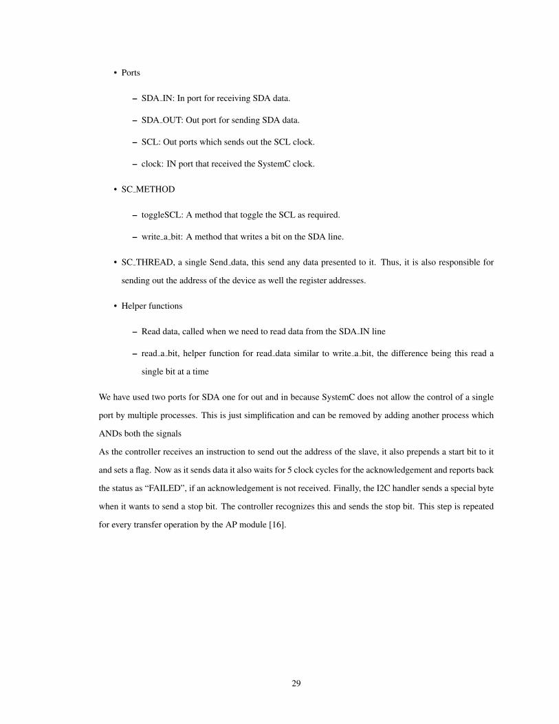
• Ports
– SDA IN: In port for receiving SDA data.
– SDA OUT: Out port for sending SDA data.
– SCL: Out ports which sends out the SCL clock.
– clock: IN port that received the SystemC clock.
• SC METHOD
– toggleSCL: A method that toggle the SCL as required.
– write a bit: A method that writes a bit on the SDA line.
• SC THREAD, a single Send data, this send any data presented to it. Thus, it is also responsible for
sending out the address of the device as well the register addresses.
• Helper functions
– Read data, called when we need to read data from the SDA IN line
– read a bit, helper function for read data similar to write a bit, the difference being this read a
single bit at a time
We have used two ports for SDA one for out and in because SystemC does not allow the control of a single
port by multiple processes. This is just simplification and can be removed by adding another process which
ANDs both the signals
As the controller receives an instruction to send out the address of the slave, it also prepends a start bit to it
and sets a flag. Now as it sends data it also waits for 5 clock cycles for the acknowledgement and reports back
the status as “FAILED”, if an acknowledgement is not received. Finally, the I2C handler sends a special byte
when it wants to send a stop bit. The controller recognizes this and sends the stop bit. This step is repeated
for every transfer operation by the AP module [16].
29

CHAPTER V
Experiment and Results
The implementation of this framework allows us the practical evaluation of our approach. The most important
aspect for the practical applicability is that the system should run in real time and allow it to connect to generic
modules with no knowledge of the underlying Greybus system. In the following sections we first briefly
describe the implementation of our design. Then we present the module we used for our experimentation
namely, the HMC5843 Compass. Finally, we present the result from the communication traces between this
test module and our framework.
V.1 Implementation Details
The design discussed in about three major blocks. These blocks exist on three different physical devices.
• For the development kit, we used the Jetson Development Kit. It has Tegra K1 SOC with 16GB of
memory. It innately supports the Android stack. For information about the setup, please refer to [11].
For our purpose, we used this device to run Android and provides USB host capability. It also has the
Greybus kernel modules loaded. These modules are available at [6].
• The USB-Bridge runs on a Beagle-Bone Black since it has the capability to act as USB slave. The USB
Bridge is derived from the gbsim 1 provided by the ARA team. It has basic constructs for receiving the
Greybus messages via a USB link. It uses the USB Gadget-Configfs Library called Libusbg2. Libusbg
is a C library encapsulating the USB gadget-configfs API functionality. We add the TCP link and the
further channeling for the SystemC application.
This Bridge was intended to be a part of the Android Board. The Linux kernel version > 3.8 provides
a kernel module called DUMMY HCD3 which allows loop back of the USB connection. However,
Android is still based on kernel < 3.14. In the future however it possible to port it to the new kernel
eliminating the use of a new device.
• The SystemC application can be run on any computer with a network device since it connects via a TCP
link. Thus, in theory, it is possible to have the machine in any corner of the world with a connection to
the Internet. However, in our system we have strict timing constraints with a quantum of 2 ms. Thus,
a direct wired connection is preferable.
1https://github.com/projectara/gbsim2https://github.com/libusbg/libusbg3http://lxr.free-electrons.com/source/drivers/usb/gadget/dummy hcd.c?v=3.14
30

• The User-Module needs to be attached and compiled together with the SystemC application. In the
main file, proper bindings for the signals should be made. When the SystemC application runs it asks
for the Manifest file of the module being tested and the IP-address of the USB-Bridge. It connects to
the USB-Bridge and sends the Manifest file-name to indicate insertion of a module.
V.2 The Compass Module
This example module had a compass module based on HMC5843 4. Since, HMC5843 interfaces using an
I2C, it serves as a good example to demonstrate the utility of the such a system. It has three in-ports for
SDA IN, clock and SCL, and one out-port for SDA OUT.
Our model of the compass module does not produce any credible data, but each time it is queried it
increases its reading by one. It also supports multiple modes, as supported by the actual data sheet. The
actual functioning of this module is straight forward. It waits in a loop reading its SDA IN line for a start bit.
As soon as it receives it gets ready for receiving an address. On receiving 8 bits, it compares its address with
the seven most significant bits of the address received. If they match, it again waits for the next 8 bits which
specify the register address in its memory. After receiving this, it read or write value from or to the register as
specified in the slave address bit, and keeps on repeating its process. When it receives the data, and it changes
any command register it makes changes to it and continues. The flowchart in FigureV.1 neatly represents the
execution.
Figure V.1: Compass Module Flow Chart
In the main file for the application, a clock is provided to the compass and it ports are attached to the ports
provided by the SystemC application, for example, SDA OUT from SystemC is connected to SDA IN from
4https://www.sparkfun.com/datasheets/Sensors/Magneto/HMC5843.pdf
31

the compass module. Now the whole system can be executed as a single executable. If we insert a Manifest,
which supports I2C protocol, we can see a device appear in the Linux devices pretending to be an I2C device.
Querying data from it would produce the compass’s ever increasing data.
V.3 Communication Traces
Th Figure V.2 shows the run of the system over a period of 20 ms. We can see the SDA lines (separated as
SDA OUT and SDA IN) in sda to master and sda to slave respectively.We can also see the SCL line. Every
tick in the graph is instance of data being sent or received.
Figure V.2: I2C data transfer over a period of 20 ms
The Figure V.3 shows a zoomed version of a single I2C transaction with the address being sent and data
being received from the compass. The master sends a start-bit and follows the address (0x03), the slave
response with the requested data. This shows that how the whole application has transformed from a highly
abstract TLM model to a cycle accurate model.
Figure V.3: Zoomed wave form of a single I2C transaction
Finally, an Android application was attached to the whole system, where we queried the data and it
responded in real time. This is where this application can be used to model systems is early stages of de-
32

velopment and allow the user, not only to simulate the hardware simulation of the module (in our example a
compass), it also allows them to model software and hardware together where they are tightly coupled.
33

CHAPTER VI
Conclusion
In this thesis, OSCI SystemC Transaction-Level Model for Project Ara was presented. Project Ara uses
UniPro protocol for communication between the modules and Greybus protocol to give semantics to the
UniPro protocol. However, it also supports legacy protocol by connecting them via a bridge called GP-
Bridge. The framework in this thesis simulates the GPBridge and allows external user defined modules to be
connected to it. The thesis describes the flow of data packet from an Application Processor to the module
that supports a legacy protocol. In doing this is it also simulates the endoskeleton and the Supervisory Con-
troller(SVC) of the Greybus system. The messages travel from a processor running an Android stack via a
USB cable to the USB-Bridge, which models the SVC controller. They now go along a TCP link to SystemC
application where they are processed, and results are sent back.
The SystemC application is modeled as an abstraction of the GPBridge using TLM 2.0 and loosely timed
coding style. This provides speed of simulation while losing accuracy. However, the application switches
to a much more refined cycle accurate model while processing the data in the final stage. It also provides
SystemC ports for connecting a generic module to the application that supports a legacy protocol. In this
thesis, only the I2C protocol is shown as an example. The whole system runs in soft real time with a quantum
of 2 ms. Thus, messages arriving faster than 2 ms may be dropped.
Finally, as an example a model of a compass which supports a compass is designed and connected to
the SystemC Application. This module presents itself to the Greybus subsystem as an I2C device. Also,
an Android application which communicates with an I2C device is installed on the Android device. This
application communicates to the I2C device without any modifications and displays the compass readings.
VI.1 Future Work
• Greybus Subsystem supports a lot of legacy protocol such as UART, GPIO, USB, I2S. These protocols
can be supported by creating appropriate handlers in the application.
• To model the Greybus subsystem ultimately, we also need to model Class Protocol. These protocols are
special protocols designed for devices primarily found in a phone, for example, a vibrator and battery.
These can also be modeled and connected to the application.
• The USB-Bridge can be incorporated in the device running the Android stack via a loopback USB
called Dummy HCD. However, it is supported on kernel >3.8. Since Android runs on kernel version
34

< 3.14, either the Android can be ported to the new kernel or DUMMY HCD patch can be developed
for the kernel. This might remove having additional hardware device required for simulation of this
system.
35

BIBLIOGRAPHY
[1] Alliance, M. (2011). Mipi alliance launches new m-phy and unipro specifications for mobile deviceapplications. Jun, 10:1.
[2] ARA, P. (2015). Project ARA faqs. http://www.projectara.com/faq/. Accessed: 2015-10-15.
[3] Association, I. S. et al. (2010). IEEE Standard for SystemVerilog–unified Hardware Design, Specification,and Verification Language. IEEE.
[4] Aynsley, J. (2009). Osci tlm-2.0 language reference manual. Open SystemC Initiative, 24.
[5] Bennett, J. (2008). Building a loosely timed soc model with osci tlm 2.0. A Case Study Using an OpenSource ISS and Linux, 2.
[6] Elder, A., O’Donoghue, B., and Porter, M. (2015). Greybus kernel modules.
[7] Gajski, D. D., Zhu, J., Domer, R., Gerstlauer, A., and Zhao, S. (2012). SPECC: Specification Languageand Methodology. Springer Science & Business Media.
[8] Ghenassia, F. et al. (2005). Transaction-level modeling with SystemC. Springer.
[9] Google (2015). Project ara module developers kit.
[10] Grotker, T., Liao, S., Martin, G., and Swan, S. (2002). System Design with SystemC. Springer Science& Business Media.
[11] Inc., M. S. (2015). Tegra board setup information.
[12] Initiative, O. S. et al. (2006). Ieee standard systemc language reference manual. IEEE Computer Society.
[13] Kroah-Hartman, G., Bolivar, M., Elder, A., and Hovold, J. (2015). Greybus-specification.
[14] Logic, B. (2014). Usb in a nutshell.
[15] Neifert, B. (2012). Thoughts on systemc tlm-2.0 and accurate models. Accessed : 2015-10-19.
[16] Semiconductors, N. (2007). I2c-bus specification and user manual. Rev, 3:19.
36