simultaneous buckling of tubing and rod strings in pumping ... · the annular production logging...
TRANSCRIPT
This is a revised version of manuscripts PO-0516-0001 (2015) and PO-0815-0022 (2016). These
manuscripts have been submitted to SPE Production & Operations. Manuscripts have been subjected to the peer
review process. In view of the reviewers' comments, these manuscripts have been declined for publication in
SPE Production & Operations.
Simultaneous Buckling Of Tubing And Rod Strings In
Pumping Wells
S.Vagapov and Sh. Vagapov, (Scientific and Production Enterprise Limited Liability Company
Burintekh, Ufa, Republic Bashkortostan, Russian Federation)
Abstract
In this paper, the phenomenon of simultaneous buckling of tubing and rod strings is explained. Rod
string is bent by the buckled tubing. Both strings are buckled during pump upstroke. This means that the buckled
sucker rod string moves inside a helically buckled tubing during pump upstroke. Interestingly, simultaneous
buckling of tubing and rod strings does not depend upon the direction of motion of the plunger but only upon the
value of the pressure drop across the plunger. In some instances, the buckled sucker rod string moves inside the
buckled tubing both upward and downward.
It is theoretically explained that the use of rod guides may entirely prevent buckling, because the energy
source of buckling disappears after the rod guides installation.
The experimental results from a study of simultaneous buckling of tubing and rod strings are given.
The annular production logging have long been used as a source of acquiring real time data in sucker
rod pumping wells. However, the simultaneous buckling of tubing and rod strings can prevent wireline tools
from passing through the annulus. As a result, the simultaneous buckling can pose extreme risk of loss to logging
tools, because the wireline twists and wraps itself around the tubing. Means for minimizing a risk of loss are
explained.
Introduction
It is well known that the lower part of freely suspended tubing buckles and wraps itself around the
sucker rod during pump upstroke (Lubinski and Blenkarn 1957). Extensive researches on this subject have been
conducted, both theoretically and experimentally. The most well known analysis of this problem have been done
by Lubinski (1957, 1962). Buckling of tubing, buckling of concentric pipes has been studied by Mitchell (1982,
2002, 2008, 2012); Paslay, P.R. and Bogy, D.B. (1964); Dawson, R. and Paslay, P.R. (1984); Miska, S. and
Cunha, J.C. (1995); Chen, Y. C., Lin, Y. H., and Cheatham, J. B. (1990); Gao, G. and Miska, S. (2008); Wenjun,
H., Deli, G., Shaolei, W. (2015) and others. In Russia (USSR), buckling of tubing, buckling of rod string has
been studied by Adonin, A.N. (1964); Virnovski, A.S. (1971); Peslyak Y.A. (1966); Muravyev, I.M. and
Mishchenko, I.T. (1967); Saroyan, A.E. (1985); Vagapov Y.G. and Sultanov, B.Z. (1980); Vagapov, S.Y. (2000)
and others.
However, in all cases these theories have always followed the same assumptions: during upstroke the
rod string remains straight in spite of the forces exerted upon it by the helically buckled tubing. The following
researches were focused more on the buckling behavior of the rod string during downstroke (Lukasiewicz, S.A.
and Knight, C. 2006; Nickens, H., Lea, J.F., Cox, J.C., et al. 2004; Zifeng, L. 1999) and others.
When consideration is given to the rod string during pump upstroke, the questions may be asked:
Why do researchers assume that the rod string remains straight?
Will the rod string be buckled during pump upstroke?
At first, it seemingly should not be buckled. The conventional wisdom says that the rod string remains
straight. In the past, theoretical works on buckling of rod string were confined to conditions for which such
buckling does not occur. However, this is not so. Both the rod and the tubing strings may be buckled during up
stroke. In this paper, the phenomenon of simultaneous buckling of tubing and rod strings is explained.
The buckling of the rod string is initiated when the energy being delivered to the rod string by the
buckled tubing is sufficient to overcome the resistance of the rod string. However, the rod string is under great
tension during upstroke. In spite of this, it is to be expected that the rod string is not capable of withstanding the
forces exerted upon it by helically buckled tubing. Why?
The rod string has much lower lateral stiffness than the lateral stiffness for tubing string. Ratio of lateral
stiffness is 50 to 215 (Table 1). Hence, the lateral stiffness for rod string may be neglected. It may be appropriate
to assume zero lateral stiffness. In addition, the radial clearance between the tubing and casing is more than the
radial clearance between the rod and tubing. This means that the simultaneous buckling of tubing and rod strings
is not limited by the casing.
Solution was obtained by use Lagrange-Dirichlet stability theorem, virtual work principle and
Timoshenko strain energy method (1955, 1956).
The investigation was based upon the following assumptions.
1. Rod and tube strings behave as linear elastic bodies.
2. Wellbore is assumed to be straight and vertical.
3. The tubing string is freely suspended in the well.
4. Friction force between the rod and the tubing strings may be neglected. Tubing and rod considered as
two separate physical entities.
5. Friction force between the buckled tubing and the constraining casing may be neglected.
6. Lateral stiffness for rod string may be neglected.
7. Inertial forces may be neglected.
8. Dynamic load may be neglected.
9. Elastic behavior induced by stretch may be neglected.
10. It is assumed that the tubing volume is kept constant during buckling.
11. Fluid level is near the pump intake.
12. No tail pipe below the pump.
13. Non tapered rod string.
Energy Source of Tubing Buckling In Pumping Well
In order to identify the root cause of buckling of tubing and rod string, the following question shall be
answered first:
What is the source of energy for buckling of the tubing in pumping wells?
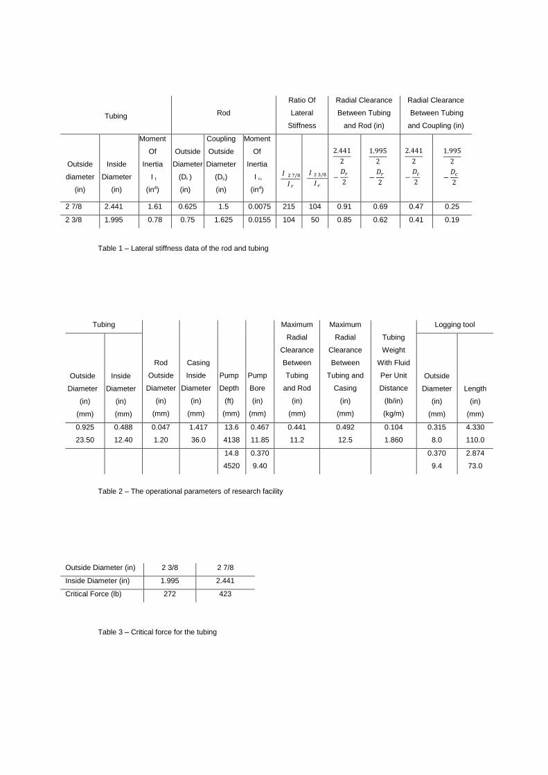
Consider a pumping well as shown in Fig.1a. We assume that the lower part of freely suspended tubing
buckles during the upstroke portion of the pumping cycle. Fig.1b shows this situation when the sucker rod string
stops the tubing deflection.
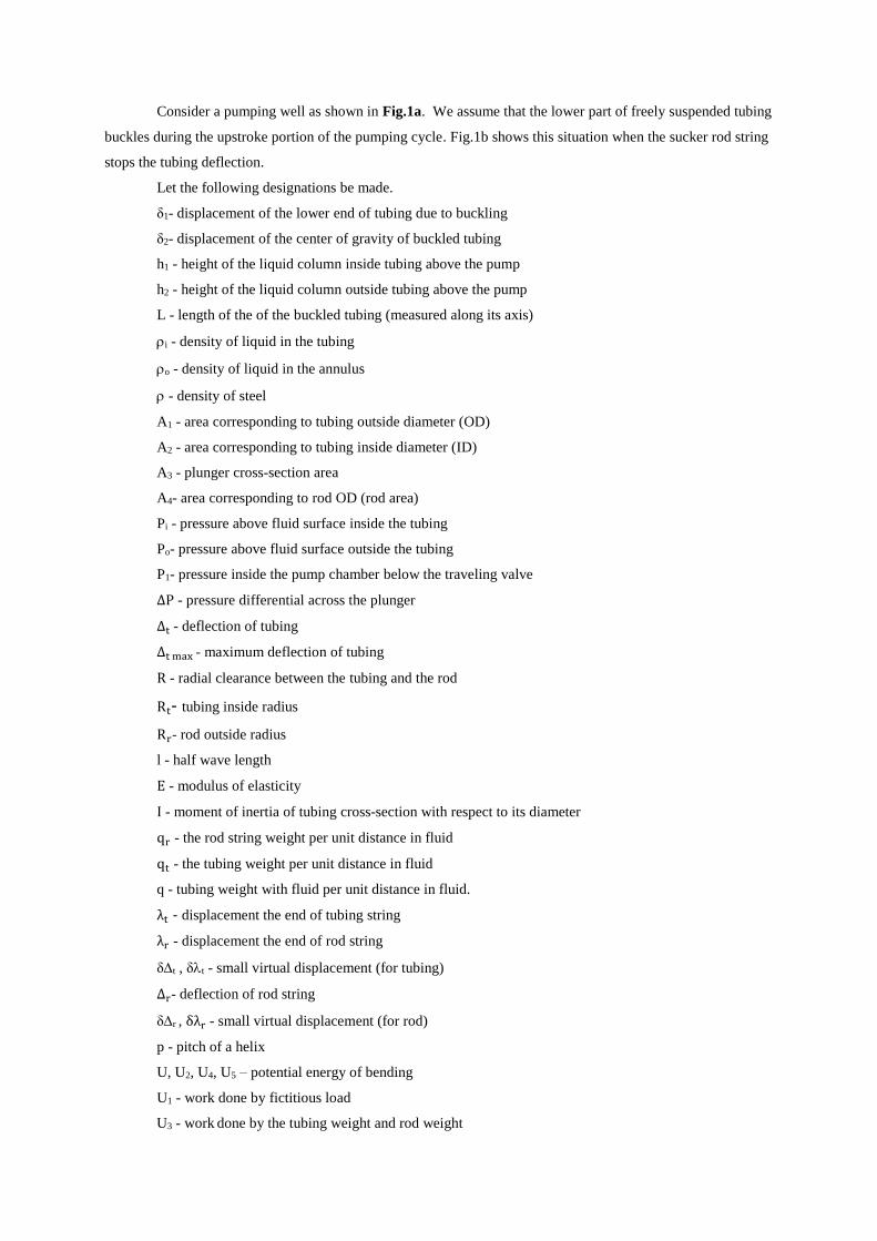
Let the following designations be made.
δ1- displacement of the lower end of tubing due to buckling
δ2- displacement of the center of gravity of buckled tubing
h1 - height of the liquid column inside tubing above the pump
h2 - height of the liquid column outside tubing above the pump
L - length of the of the buckled tubing (measured along its axis)
i - density of liquid in the tubing
o - density of liquid in the annulus
- density of steel
A1 - area corresponding to tubing outside diameter (OD)
A2 - area corresponding to tubing inside diameter (ID)
A3 - plunger cross-section area
A4- area corresponding to rod OD (rod area)
Pi - pressure above fluid surface inside the tubing
Po- pressure above fluid surface outside the tubing
P1- pressure inside the pump chamber below the traveling valve
∆P - pressure differential across the plunger
∆t - deflection of tubing
∆t max - maximum deflection of tubing
R - radial clearance between the tubing and the rod
Rt- tubing inside radius
Rr- rod outside radius
l - half wave length
E - modulus of elasticity
I - moment of inertia of tubing cross-section with respect to its diameter
qr - the rod string weight per unit distance in fluid
qt - the tubing weight per unit distance in fluid
q - tubing weight with fluid per unit distance in fluid.
λt - displacement the end of tubing string
λr - displacement the end of rod string
δt , δt - small virtual displacement (for tubing)
∆r- deflection of rod string
δr , δλr - small virtual displacement (for rod)
p - pitch of a helix
U, U2, U4, U5 – potential energy of bending
U1 - work done by fictitious load
U3 - work done by the tubing weight and rod weight
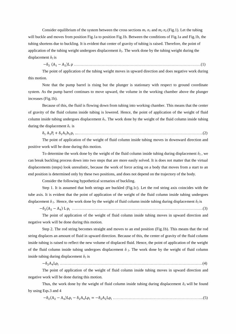
Consider equilibrium of the system between the cross sections m1 n1 and m2 n2 (Fig.1). Let the tubing
will buckle and moves from position Fig.1a to position Fig.1b. Between the conditions of Fig.1a and Fig.1b, the
tubing shortens due to buckling. It is evident that center of gravity of tubing is raised. Therefore, the point of
application of the tubing weight undergoes displacement δ2. The work done by the tubing weight during the
displacement δ2 is
−δ2 (A1 − A2)L ρ ……………………………………………………………………………………(1)
The point of application of the tubing weight moves in upward direction and does negative work during
this motion.
Note that the pump barrel is rising but the plunger is stationary with respect to ground coordinate
system. As the pump barrel continues to move upward, the volume in the working chamber above the plunger
increases (Fig.1b).
Because of this, the fluid is flowing down from tubing into working chamber. This means that the center
of gravity of the fluid column inside tubing is lowered. Hence, the point of application of the weight of fluid
column inside tubing undergoes displacement δ1. The work done by the weight of the fluid column inside tubing
during the displacement δ1 is
δ1 A3Pi + δ1A3h1ρi ...…………………………………………………………………………………..(2)
The point of application of the weight of fluid column inside tubing moves in downward direction and
positive work will be done during this motion.
To determine the work done by the weight of the fluid column inside tubing during displacement δ2 , we
can break buckling process down into two steps that are more easily solved. It is does not matter that the virtual
displacements (steps) look unrealistic, because the work of force acting on a body that moves from a start to an
end position is determined only by these two positions, and does not depend on the trajectory of the body.
Consider the following hypothetical scenarios of buckling.
Step 1. It is assumed that both strings are buckled (Fig.1c). Let the rod string axis coincides with the
tube axis. It is evident that the point of application of the weight of the fluid column inside tubing undergoes
displacement δ 2. Hence, the work done by the weight of fluid column inside tubing during displacement δ2 is
−δ2(A2 − A4) L ρi ………………………………………………………………………………………(3)
The point of application of the weight of fluid column inside tubing moves in upward direction and
negative work will be done during this motion.
Step 2. The rod string becomes straight and moves to an end position (Fig.1b). This means that the rod
string displaces an amount of fluid in upward direction. Because of this, the center of gravity of the fluid column
inside tubing is raised to reflect the new volume of displaced fluid. Hence, the point of application of the weight
of the fluid column inside tubing undergoes displacement δ 2. The work done by the weight of fluid column
inside tubing during displacement δ2 is
−δ2A4Lρi ………………………………………………………………………………………………(4)
The point of application of the weight of fluid column inside tubing moves in upward direction and
negative work will be done during this motion.
Thus, the work done by the weight of fluid column inside tubing during displacement δ2 will be found
by using Eqs.3 and 4
−δ2(A2 − A4)Lρi − δ2A4Lρi = −δ2A2Lρi …………………………………………………………...(5)
To determine the work done by the weight of fluid column outside tubing during displacement δ2, we
can break buckling process down into two hypothetical scenarios of buckling.
Step 1. It is assumed that the plunger is rising but stationary with respect to the pump barrel (Fig 1d).
This means that the tubing string displaces an amount of fluid outside tubing in downward direction. Because of
this, the center of gravity of the fluid column outside tubing is lowered to reflect the new volume of displaced
fluid. Therefore, the point of application of the weight of fluid column outside tubing undergoes displacement δ2.
The work done by the weight of fluid column inside tubing during displacement δ2 is
δ2A1Lρ0 ………………………………………………………………………………………………..(6)
The point of application of the weight of fluid column outside tubing moves in downward direction and
positive work will be done during this motion.
Step 2. The plunger moves to an end position in downward direction (Fig.1b). This means that the
plunger displaces fluid into the annulus. The work done by the pressure (pressure-volume work) in the working
chamber will be
−δ1A3P1 ………………………………………………………………………………………………..(7)
where P1 = (h2 o + Po) - pressure inside the pump chamber below the traveling valve.
The point of application of the weight of fluid column outside tubing moves in upward direction and
negative work will be done during this motion.
Thus, the work done by the weight of fluid column outside tubing during displacement δ2 will be found
by using Eqs.6 and 7.
Following the energy method (Timoshenko 1955), the strain energy to the work done by the load during
deflection, may be obtain by assuming the tubing is only compressed by a centrally applied load F.
Consequently, the work done by the load F during displacement δ1 will be transformed into potential energy of
strain. Hence, strain energy of bending stored in the tubing during upstroke is
−Fδ1 …………………………………………………………………………………………................(8)
The point of application of the load moves in upward direction and negative work will be done during
displacement δ1.
The principle of virtual displacement states that the virtual work done by the actual forces is zero if and
only if the body is in equilibrium.
Thus, the total work done by the forces within on a system is
−δ2(A1 − A2)Lρ + δ1A3Pi + δ1A3h1ρi − δ2A2Lρi + δ2A1Lρ0 − δ1A3P1 − Fδ1 = 0 ………………(9)
Using the notation ∆P = (h1ρi + Pi) − (h2ρ0 + P0) and q = (A1 − A2)ρ + A2ρi − A1ρ0 this equation
may be transformed into the significantly simpler form
δ1A3∆P − σ2Lq − Fδ1 = 0 …………………………………………………………………………………. (10)
It should be noted, that P is the pressure differential across the plunger, q is the tubing weight with
fluid per unit distance in fluid.
Let us consider equation in more detail.
The first term (δ1A3 P) is the positive work done by the force (A3 P) during displacement δ1. The sign
of the two terms (- δ2Lq – Fδ1) are negative.
This equation shows that the source of energy for buckling of tubing in pumping wells is the pressure
differential across the plunger during upstroke. So one can conclude that the positive work (δ1A3 P) necessary
to buckle tubing is the work done by the weight of fluid column inside tubing during displacement δ1.
It is well known that condition of equilibrium is obtained by minimizing the total potential energy of
the system (Lagrange-Dirichlet stability theorem). It is to be remembered that following the energy method,
buckling occurs when the work done by the weight of fluid column inside tubing (δ1A3 P) exceeds to the sum
of the potential energy of bending (F δ1) and the work done by the tubing weight with fluid (δ2 Lq) during
upstroke.
At the beginning of the upstroke, the tubing is buckled while the rod string is straight. The pump barrel
is rising but the plunger is stationary with respect to ground coordinate system. As the pump barrel continues to
move upward, the plunger undergoes displacement with respect to the working chamber and the volume in the
working chamber above the plunger increases. Because of this, the fluid column inside tubing moves in
downward direction and does the positive work δ1A3 P necessary to induce buckling. This means that the center
of gravity and potential energy of system is lowered.
On the other hand, Lubinski A. and Blenkarn K.A. (1957) proposed so-called "fictitious force" in the
analysis of tubing buckling in pumping wells. During pump upstroke the tubing will buckle as if subjected to an
upward fictitious load and equal to
F = A3∆P …………………………………………………………………………………………….(11)
where P is the pressure differential across the plunger.
Comparing this with the Eq.10 we conclude, that the positive work necessary to buckle tubing is equal
to the work done by the fictitious load during displacement δ1.
It should be noted, that the tubing buckles being under great tension. In fact, the compressive force does
not exist; tubing buckling is due to the bending moment. Based on the terminology of Lagrange mechanics the
fictitious load F can be considered as a generalized force and the displacement δ1 can be considered as a
generalized displacement.
Simultaneous Buckling of Tubing and Rod Strings
Lagrange-Dirichlet stability theorem states that the condition of equilibrium is obtained by minimizing
the total potential energy of the system. Let us determine the deflection of the tube with the rod corresponding to
the minimum total potential energy of the system.
Lateral Configuration. The tubing is assumed to buckle into a lateral shape. The value of deflection
may be found by using principle of virtual displacement. Taking the case of the buckled tubing string shown in
Fig.2, deflection curve may be represented by the simple sinusoidal curve (Timoshenko 1955)
уt = ∆t sin πx
l ……………………………………………………….………….………………………………(12)
The displacement the end of tubing string is (Timoshenko 1955)
λt =1
2∫ (
dyt
dx)
2
dx ………………………………………………………….………………………….(13)
The derivative of y, from (12), is
dуt
dx= π
∆t
lcos π
x
l ……………………..…………………………………..………..….…………….(14)
It is well known, that
cos2α =1
2+
1
2cos 2α………………………………………………………..…………………………(15)
Then by using Eq.15 and substituting Eq.14 into Eq.13, the general solution is
λt = (π∆t
2l)
2
(x −l
2πsin 2π
x
l) + C ………………………………………………..………….……….(16)
where C is constant of integration which must be adjusted to satisfy the conditions x = 0, = 0. These
conditions are fulfilled, if C = 0.
Integrating this between the limits 0 and 2l, we find
λt =π2∆t
2
2l ……………………………………………………………………….…………….……...(17)
The displacement of the end of tubing string may be calculated from this expression.
We assume that the tubing string undergoes a small virtual displacement δt as shown in Fig.2. It is
evident that the end of the tubing string undergoes a small virtual displacement δt during a small virtual
displacement δt.
Substituting into Eq.17, we have
λt + δλt =π2
2l(∆t + δ∆t)
2 ………………………………………………………...…………………(18)
Using the notation π2
2l= K and λt = t
2 K (see Eq.17), this equation may be transformed into the form
δλt = K(∆t2 + 2∆tδ∆t + δ∆t
2 − ∆t2) ………………………………………………………………(19)
Let's make the following assumption: the value of deflection t is large compared a small virtual
displacement δ∆t , therefore the value δt 2 may be neglected.
Equation then becomes
δλt =π2
l∆tδ∆t ………………………………………………………………………………………...(20)
Equation gives the displacement of the end of tubing string as a function of the deflection.
Consider now rod string movement due to buckling.
Let us determine displacement of the end of rod string corresponding to its deflection.
Taking the case of the buckled rod string shown in Fig.2, deflection curve may be represented by the
simple sinusoidal curve (Timoshenko 1955). It should be noted (see Fig.2) that the half wave length of the
buckled tubing equals the half wave length of the buckled rod string.
уr = ∆r sin πx
l ………………………………………………………………..………………………(21)
where r = t - (Rt – Rr), where Rt is inside radius of the tubing and Rr is outside radius of the rod (see
Fig.2).
Based on the results of previous discussion (see Eq.20), the displacement of the end of rod string may
be found
δλr =π2
l∆rδ∆t ……………………………………………………………………………………….(22)
where δt = δr , (see Fig.2).
Consider now this equation and Eq.20.
The end of tubing undergoes displacement δt and the end of rod string undergoes displacement δr
during simultaneous buckling of rod and tubing. This means that the plunger undergoes displacement δt - δr
with respect to working chamber.
It has been explained previously that the positive work necessary to buckle tubing is equal to the work
done by fictitious load during displacement δ1 (see Eqs.10 and 11). Hence, the positive work U1 necessary to
buckle tubing and rod is equal to the work done by fictitious load during displacement δt - δr.
U1 = A3∆P(δλt − δλr) ……………………………………………………………………………….(23)
where A3 is the plunger cross-section area,
P is the pressure differential across the plunger.
Substituting Eqs.20 and 22 and observing that t - r = Rt – Rr (see Fig.2) we obtain
U1 = A3∆Pπ2 δ∆t
l(Rt − Rr) ……….……………………………………………………………….....(24)
The simultaneous buckling of rod and tubing occurs when the positive work U1 exceeds to the sum of
the potential energy of bending U2 and work U3 done by the tubing weight and rod weight during displacement
δt - δr .
U1 = U2 + U3 …………………………………………………………………………………………(25)
Let us estimate the maximum deflection for buckled columns.
The tubing will buckle more severely in the vicinity of the pump. We assume that the work done by the
weight of tubing and rod may be neglected (there is no tail pipe below the pump), U3 = 0.
The strain energy of bending is (Timoshenko 1955)
U =EI
2∫ (
d2y
dx2)2
dx …………………………………………………………………………………...(26)
where E is the modulus of elasticity,
I is the moment of inertia of tubing cross-section with respect to its diameter (the lateral stiffness for rod
string may be neglected (see assumptions)).
Since the assumption is that the lateral stiffness for rod string may be neglected, the strain energy of
bending in the rod string need not be considered.
The second derivative of y, from (12), is
d2уt
dx2 = −∆t (π
l)
2
sinπ
lx …………………...………………………………………………………….(27)
The general solution is
EI∆t2 (
π
l)
3
(2πx
l− sin 2π
x
l) + C ……………………………………………………………………(28)
In which C is constant of integration which must be adjusted to satisfy the conditions x = 0, U = 0.
These conditions are fulfilled if C = 0.
Integrating this between the limits 0 and 2l, we find
U = ∆t2π4 EI
2l3 ………………………………………………………………………………………….(29)
The strain energy stored in the tubing during deflection δt is
U2 = U4 − U5 ....……………………………………………………………………………………...(30)
where U4 is the strain energy stored in the tubing during deflection t + δt ,
U5 is the strain energy stored in the tubing during deflection t .
Therefore
U2 = π4 EI
2l3(∆t + δ∆t)2 − π4 EI
2l3 ∆t2 …………………………………………………………………(31)

As it has been mentioned above, the value δt 2 may be neglected. Hence, this equation may be
transformed into the significantly simpler form
U2 = ∆tδ∆tπ4 EI
l3 …..………………………………………………………………………………….(32)
Substituting Eqs. 24 and 32 into Eq.25 and observing U3 = 0, we obtain
A3∆Pπ2 δ∆t
l(Rt − Rr) = ∆tδ∆tπ
4 EI
l3 …………………………………………………………………..(33)
Then
∆t max = A3∆P(Rt − Rr)l2
π2EI ………………………………………………………….……………...(34)
This equation gives the maximum deflection for the laterally buckled columns corresponding to the
minimum total potential energy of the system.
Consider the numerical example from a paper Lubinski and Blenkarn (1957)
A3 = 2.4 in2. (1 ¾ in. plunger).
P = 2,500 psi (working fluid level 5,000 ft., gradient 0.5 psi/ft, i.e., fluid specific gravity 1.154).
Pump depth 6,000 ft.
Tubing size, 2 7/8 (OD = 2.875, ID = 2.441) in., q t = 6.4 lbm/ft.
E = 30 х 106 psi.
Rod size ¾ (0.75) in., q r = 1.634 lbm/ft., sucker rod coupling OD = 1.625 in.
Casing size, 5 ½ (OD = 5.5, ID = 5.012) in.
Determine the amount of deflection during pump upstroke from Eq.34.
Solution. The moment of inertia of the tubing is
I =π 2.8754
64(1 −
2.4414
2.8754) = 1.61 in4
The half wave length is (Timoshenko 1955)
l = π√EI
A3∆P= 3.14√
30×106×1.61
2.4×2,500= 282 in.
The wave length is 282 x 2 = 564 in.
Substituting these into Eq.34, we have
∆t= 2.4 × 2,500 (2.441
2−
0.75
2)
5642
3.142×30×106×1.61= 3.39 in.
Thus, for the above example the maximum deflection for the tube due to the lateral buckling is 3.39 in.
However, the radial clearance between the rod and the tubing is 2.441−0.75
2= 0.845 in. This means that the rod
string is bent by the buckled tubing during pump upstroke. On the other hand, buckling is limited by the casing.
The radial clearance between the tubing and the casing is 5.012−2.875
2= 1.078 in. Until the clearance between the
tubing and the casing is large enough, the tubing will still buckle the rod string. However, if the lateral
displacements are constrained (i.e. a casing constraint), then contact of the buckled tubing with the constraint
will induce a rearrangement to a helix form. For this reason, the buckled sucker rods move inside a helically
buckled tubing during pump upstroke.
Helical Configuration. The tubing is assumed to buckle into a helical shape. It has been mentioned
above that the equilibrium position of a conservative mechanical system is stable if the potential energy U
assumes a minimum at this equilibrium. Let us determine the maximum deflection for buckled columns shown
in Fig.3 by using this theorem.
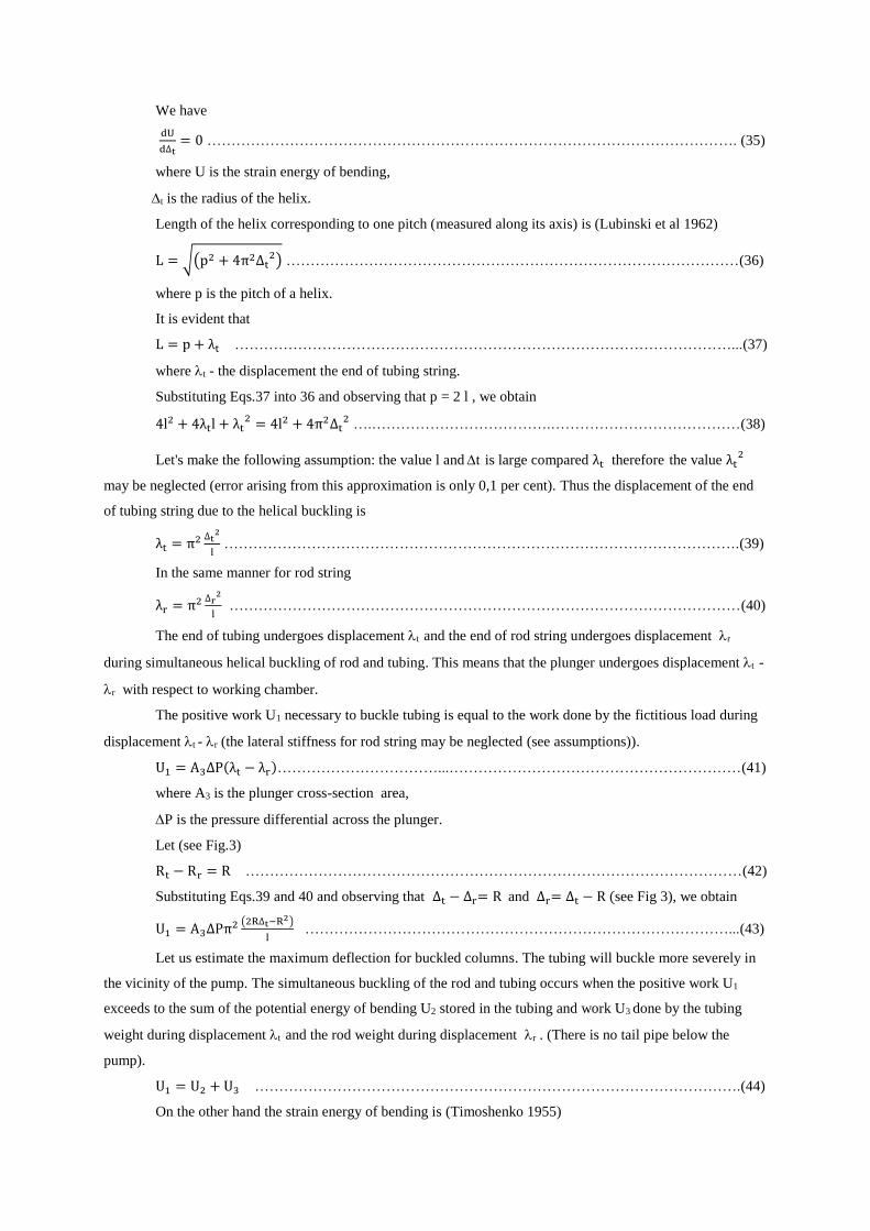
We have
dU
d∆t= 0 ………………………………………………………………………………………………. (35)
where U is the strain energy of bending,
t is the radius of the helix.
Length of the helix corresponding to one pitch (measured along its axis) is (Lubinski et al 1962)
L = √(p2 + 4π2∆t2) …………………………………………………………………………………(36)
where p is the pitch of a helix.
It is evident that
L = p + λt …………………………………………………………………………………………...(37)
where t - the displacement the end of tubing string.
Substituting Eqs.37 into 36 and observing that p = 2 l , we obtain
4l2 + 4λtl + λt2 = 4l2 + 4π2∆t
2 ….……………………………….…………………………………(38)
Let's make the following assumption: the value l and t is large compared λt therefore the value λt2
may be neglected (error arising from this approximation is only 0,1 per cent). Thus the displacement of the end
of tubing string due to the helical buckling is
λt = π2 ∆t2
l …………………………………………………………………………………………….(39)
In the same manner for rod string
λr = π2 ∆r2
l ……………………………………………………………………………………………(40)
The end of tubing undergoes displacement t and the end of rod string undergoes displacement r
during simultaneous helical buckling of rod and tubing. This means that the plunger undergoes displacement t -
r with respect to working chamber.
The positive work U1 necessary to buckle tubing is equal to the work done by the fictitious load during
displacement t - r (the lateral stiffness for rod string may be neglected (see assumptions)).
U1 = A3∆P(λt − λr)……………………………...……………………………………………………(41)
where A3 is the plunger cross-section area,
P is the pressure differential across the plunger.
Let (see Fig.3)
Rt − Rr = R …………………………………………………………………………………………(42)
Substituting Eqs.39 and 40 and observing that ∆t − ∆r= R and ∆r= ∆t − R (see Fig 3), we obtain
U1 = A3∆Pπ2 (2R∆t−R2)
l ……………………………………………………………………………...(43)
Let us estimate the maximum deflection for buckled columns. The tubing will buckle more severely in
the vicinity of the pump. The simultaneous buckling of the rod and tubing occurs when the positive work U1
exceeds to the sum of the potential energy of bending U2 stored in the tubing and work U3 done by the tubing
weight during displacement t and the rod weight during displacement r . (There is no tail pipe below the
pump).
U1 = U2 + U3 ……………………………………………………………………………………….(44)
On the other hand the strain energy of bending is (Timoshenko 1955)
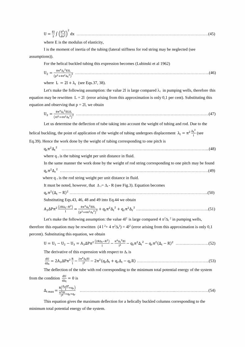
U =EI
2∫ (
d2y
dx2)2
dx ……………………………………………………………………………………(45)
where E is the modulus of elasticity,
I is the moment of inertia of the tubing (lateral stiffness for rod string may be neglected (see
assumptions)).
For the helical buckled tubing this expression becomes (Lubinski et al 1962)
U2 =8π4∆t
2EIL
(p2+4π2∆t2)
2 ……………………………………………………………………………………..(46)
where L = 2l + λt (see Eqs.37, 38).
Let's make the following assumption: the value 2l is large compared t in pumping wells, therefore this
equation may be rewritten L = 2l (error arising from this approximation is only 0,1 per cent). Substituting this
equation and observing that p = 2l, we obtain
U2 =8π4∆t
2EI2L
(4l2+4π2∆t2)
2 …………………………………………………………………………………….(47)
Let us determine the deflection of tube taking into account the weight of tubing and rod. Due to the
helical buckling, the point of application of the weight of tubing undergoes displacement λt = π2 ∆t2
l (see
Eq.39). Hence the work done by the weight of tubing corresponding to one pitch is
qtπ2∆t2 ……………………………………………………………………………………………...(48)
where q t is the tubing weight per unit distance in fluid.
In the same manner the work done by the weight of rod string corresponding to one pitch may be found
qrπ2∆r2 ………………………………………………………………………………………………(49)
where q r is the rod string weight per unit distance in fluid.
It must be noted, however, that r= t - R (see Fig.3). Equation becomes
qrπ2(∆t − R)2 ………………………………………………………………………………………..(50)
Substituting Eqs.43, 46, 48 and 49 into Eq.44 we obtain
A3∆Pπ2 (2R∆t−R2)
l=
8π4∆t2EIL
(p2+4π2∆t2)
2 + qtπ2∆t2 + qrπ2∆r
2 ……………………………………………..(51)
Let's make the following assumption: the value 4l2 is large compared 4 2t 2 in pumping wells,
therefore this equation may be rewritten (4 l 2+ 4 2t2) = 4l2 (error arising from this approximation is only 0,1
percent). Substituting this equation, we obtain
U = U1 − U2 − U3 = A3∆Pπ2 (2R∆t−R2)
l−
π4∆t2EI
l3 − qtπ2∆t2 − qrπ2(∆t − R)2 ……………………(52)
The derivative of this expression with respect to t is
dU
d∆t= 2A3∆Pπ2 R
l−
2π4∆tEI
l3 − 2π2(qt∆t + qr∆t − qrR) ……………………………………………..(53)
The deflection of the tube with rod corresponding to the minimum total potential energy of the system
from the condition dU
d∆t= 0 is
∆t max =R(
A3∆P
l+qr)
π2EI
l3 +qt+qr
…………………………………………………..………...……………………(54)
This equation gives the maximum deflection for a helically buckled columns corresponding to the
minimum total potential energy of the system.
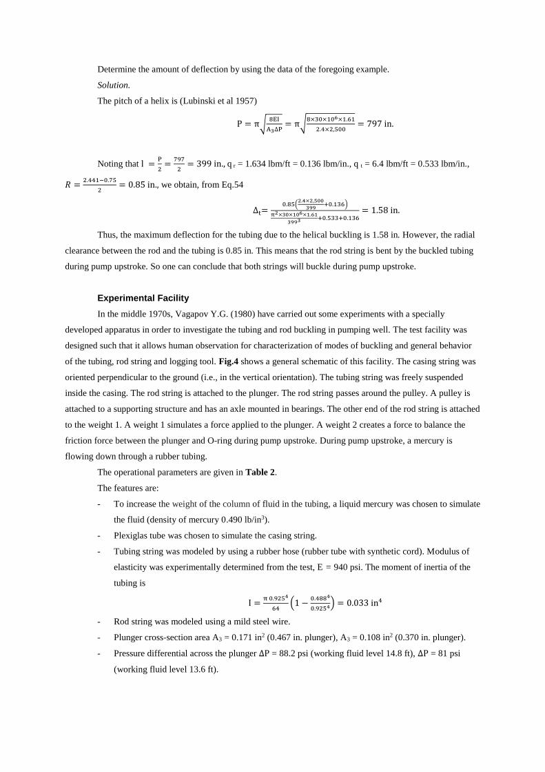
Determine the amount of deflection by using the data of the foregoing example.
Solution.
The pitch of a helix is (Lubinski et al 1957)
P = π√8EI
A3∆P= π√
8×30×106×1.61
2.4×2,500= 797 in.
Noting that l =P
2=
797
2= 399 in., q r = 1.634 lbm/ft = 0.136 lbm/in., q t = 6.4 lbm/ft = 0.533 lbm/in.,
𝑅 =2.441−0.75
2= 0.85 in., we obtain, from Eq.54
∆t=0.85(
2.4×2,500
399+0.136)
π2×30×106×1.61
3993 +0.533+0.136= 1.58 in.
Thus, the maximum deflection for the tubing due to the helical buckling is 1.58 in. However, the radial
clearance between the rod and the tubing is 0.85 in. This means that the rod string is bent by the buckled tubing
during pump upstroke. So one can conclude that both strings will buckle during pump upstroke.
Experimental Facility
In the middle 1970s, Vagapov Y.G. (1980) have carried out some experiments with a specially
developed apparatus in order to investigate the tubing and rod buckling in pumping well. The test facility was
designed such that it allows human observation for characterization of modes of buckling and general behavior
of the tubing, rod string and logging tool. Fig.4 shows a general schematic of this facility. The casing string was
oriented perpendicular to the ground (i.e., in the vertical orientation). The tubing string was freely suspended
inside the casing. The rod string is attached to the plunger. The rod string passes around the pulley. A pulley is
attached to a supporting structure and has an axle mounted in bearings. The other end of the rod string is attached
to the weight 1. A weight 1 simulates a force applied to the plunger. A weight 2 creates a force to balance the
friction force between the plunger and O-ring during pump upstroke. During pump upstroke, a mercury is
flowing down through a rubber tubing.
The operational parameters are given in Table 2.
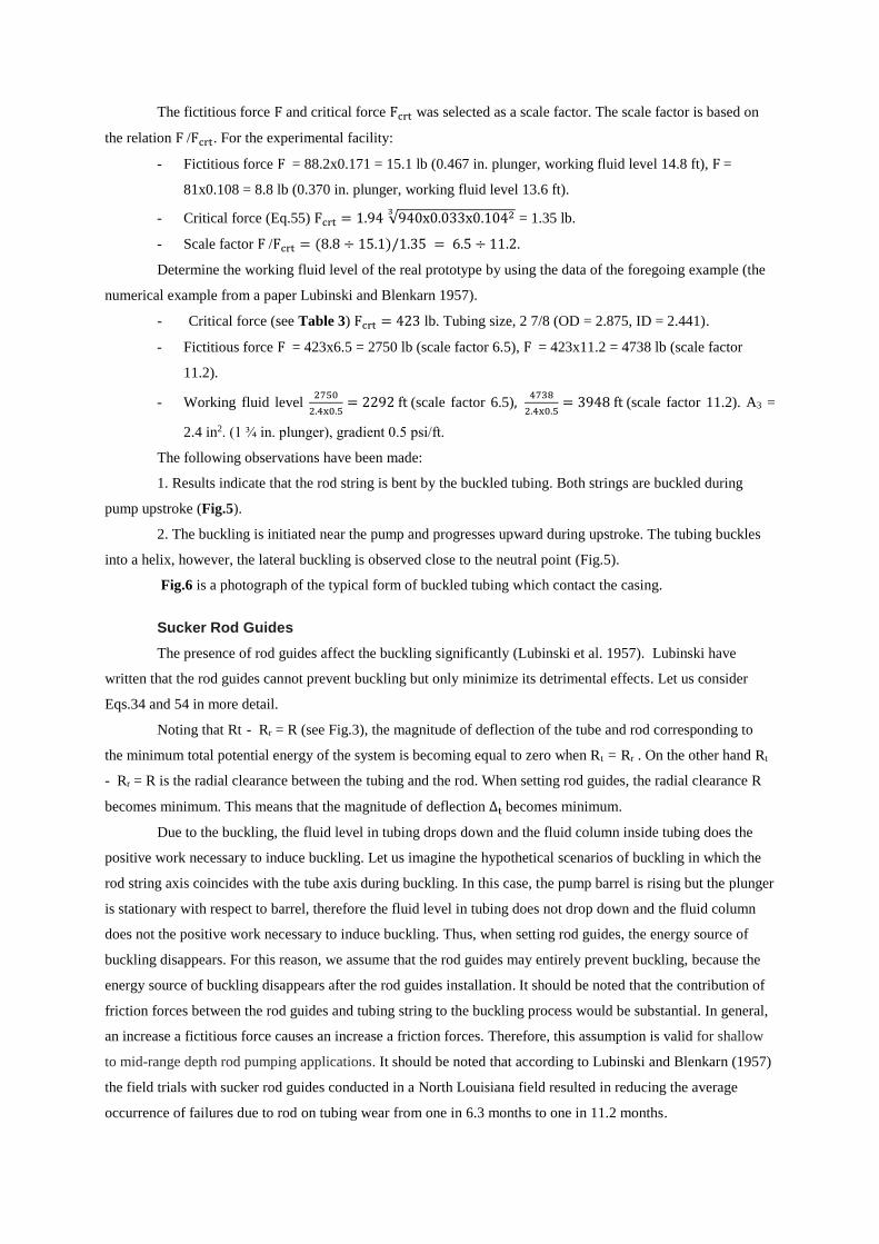
The features are:
- To increase the weight of the column of fluid in the tubing, a liquid mercury was chosen to simulate
the fluid (density of mercury 0.490 lb/in3).
- Plexiglas tube was chosen to simulate the casing string.
- Tubing string was modeled by using a rubber hose (rubber tube with synthetic cord). Modulus of
elasticity was experimentally determined from the test, E = 940 psi. The moment of inertia of the
tubing is
I =π 0.9254
64(1 −
0.4884
0.9254) = 0.033 in4
- Rod string was modeled using a mild steel wire.
- Plunger cross-section area A3 = 0.171 in2 (0.467 in. plunger), A3 = 0.108 in2 (0.370 in. plunger).
- Pressure differential across the plunger ∆P = 88.2 psi (working fluid level 14.8 ft), ∆P = 81 psi
(working fluid level 13.6 ft).
The fictitious force F and critical force Fcrt was selected as a scale factor. The scale factor is based on
the relation F /Fcrt. For the experimental facility:
- Fictitious force F = 88.2x0.171 = 15.1 lb (0.467 in. plunger, working fluid level 14.8 ft), F =
81x0.108 = 8.8 lb (0.370 in. plunger, working fluid level 13.6 ft).
- Critical force (Eq.55) Fcrt = 1.94 √940x0.033x0.10423 = 1.35 lb.
- Scale factor F /Fcrt = (8.8 ÷ 15.1)/1.35 = 6.5 ÷ 11.2.
Determine the working fluid level of the real prototype by using the data of the foregoing example (the
numerical example from a paper Lubinski and Blenkarn 1957).
- Critical force (see Table 3) Fcrt = 423 lb. Tubing size, 2 7/8 (OD = 2.875, ID = 2.441).
- Fictitious force F = 423x6.5 = 2750 lb (scale factor 6.5), F = 423x11.2 = 4738 lb (scale factor
11.2).
- Working fluid level 2750
2.4x0.5= 2292 ft (scale factor 6.5),
4738
2.4x0.5= 3948 ft (scale factor 11.2). A3 =
2.4 in2. (1 ¾ in. plunger), gradient 0.5 psi/ft.
The following observations have been made:
1. Results indicate that the rod string is bent by the buckled tubing. Both strings are buckled during
pump upstroke (Fig.5).
2. The buckling is initiated near the pump and progresses upward during upstroke. The tubing buckles
into a helix, however, the lateral buckling is observed close to the neutral point (Fig.5).
Fig.6 is a photograph of the typical form of buckled tubing which contact the casing.
Sucker Rod Guides
The presence of rod guides affect the buckling significantly (Lubinski et al. 1957). Lubinski have
written that the rod guides cannot prevent buckling but only minimize its detrimental effects. Let us consider
Eqs.34 and 54 in more detail.
Noting that Rt - Rr = R (see Fig.3), the magnitude of deflection of the tube and rod corresponding to
the minimum total potential energy of the system is becoming equal to zero when Rt = Rr . On the other hand Rt
- Rr = R is the radial clearance between the tubing and the rod. When setting rod guides, the radial clearance R
becomes minimum. This means that the magnitude of deflection ∆t becomes minimum.
Due to the buckling, the fluid level in tubing drops down and the fluid column inside tubing does the
positive work necessary to induce buckling. Let us imagine the hypothetical scenarios of buckling in which the
rod string axis coincides with the tube axis during buckling. In this case, the pump barrel is rising but the plunger
is stationary with respect to barrel, therefore the fluid level in tubing does not drop down and the fluid column
does not the positive work necessary to induce buckling. Thus, when setting rod guides, the energy source of
buckling disappears. For this reason, we assume that the rod guides may entirely prevent buckling, because the
energy source of buckling disappears after the rod guides installation. It should be noted that the contribution of
friction forces between the rod guides and tubing string to the buckling process would be substantial. In general,
an increase a fictitious force causes an increase a friction forces. Therefore, this assumption is valid for shallow
to mid-range depth rod pumping applications. It should be noted that according to Lubinski and Blenkarn (1957)
the field trials with sucker rod guides conducted in a North Louisiana field resulted in reducing the average
occurrence of failures due to rod on tubing wear from one in 6.3 months to one in 11.2 months.
In order to effective prevent buckling effect, the rod guides must be properly spaced on the sucker rod
string. The rod guides must be set so that the axis of the sucker rod string coincides with the axis of the tubing
string during buckling. The rod guides must be molded directly onto the rod body and must not move on the rods.
The outside diameter of rod guides should be as close to the inside diameter of tubing as possible. It should be
noted, that the rod guides would prevent buckling but not breathing.
Annulus Production Logging
The annulus production logging have long been used as a source of acquiring real time data in sucker
rod pumping wells (Hammack, G.W. et al.1976). The logging is done through the annulus between the tubing
and casing. Before logging, the well must be prepared by removing the tubing anchor. For freely suspended
tubing, the rod string is bent by the buckled tubing and the buckled tubing will contact the wall of the casing. For
this reason, the simultaneous buckling of tubing and rod strings can prevent wireline tools from passing through
the annulus. Therefore, the simultaneous buckling of tubing and rod strings can pose extreme risk of loss to
logging tools, because the wireline twists and wraps itself around the tubing.
In practice, the walking beam stops when the horsehead reaches the uppermost position to gain access
to the wellhead equipment (Fig.7). Typically, the walking beam stops during upstroke, when the rod string is
under the great tension and the tubing is buckled. That is not correct. To avoid the tool loss, several procedures
should be followed before and during logging operations in sucker rod pumping well.
Procedure 1. Well is under static conditions.
1. Shut down pump jack and lock in place. To provide access to the wellhead equipment, the walking
beam must be stopped in the upper position, however, during downstroke (Fig.7, right). The standing valve must
be closed and the traveling valve must be opened. Because of this, the fluid load is transferred to the tubing
string as a result the tubing string is straight and is under the great tension. However, one should keep in mind
that the tubing buckling does not depend upon the direction of motion of the plunger but only upon the value of
the pressure drop across the plunger. The tubing may be buckled (traveling valve is closed) even during
downstroke.
The fictitious force is much greater than the critical force in the great majority of pumping wells
(Appendix A). For this reason, the buckling period is approximately equal to the upstroke period during pumping
cycle. Fig.8 and Fig.9 show areas indicating periods where buckling occurs (1-2-3-4). In some cases, the tubing
may be buckled both upstroke and downstroke (Fig.9, gas interference situation). Therefore, in some instances,
the rod string is bent by the buckled tubing and moves both upward and downward. This means that additional
information must be observed on a pump card during logging. The load on the polished rod must be monitored to
determine whether or not the travelling valve is opened during pump downstroke.
2. During logging operations, the load on the polished rod must be monitored to predict simultaneous
buckling. If the standing valve is leaking, the traveling valve ball will seat. As a result, the dynamometer will
measure a load increase on the polished rod. This means that the tubing begins to bend the rod string. For this
reason, the well logging must be stopped and the pumping unit must be restarted to repeat the cycle. Once the
traveling valve is opened, the well logging may be restarted.
Procedure 2. Well is under dynamic, producing conditions.
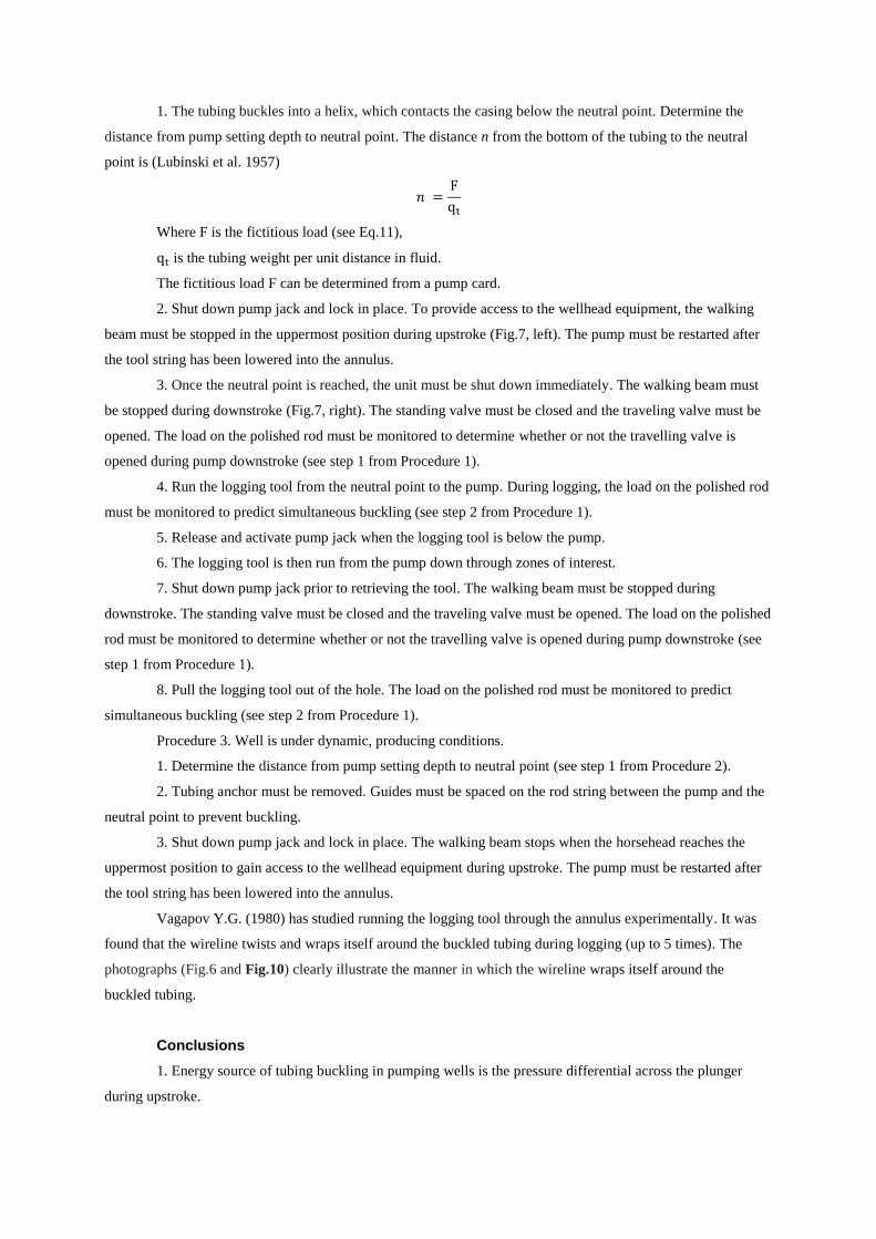
1. The tubing buckles into a helix, which contacts the casing below the neutral point. Determine the
distance from pump setting depth to neutral point. The distance n from the bottom of the tubing to the neutral
point is (Lubinski et al. 1957)
𝑛 =F
qt
Where F is the fictitious load (see Eq.11),
qt is the tubing weight per unit distance in fluid.
The fictitious load F can be determined from a pump card.
2. Shut down pump jack and lock in place. To provide access to the wellhead equipment, the walking
beam must be stopped in the uppermost position during upstroke (Fig.7, left). The pump must be restarted after
the tool string has been lowered into the annulus.
3. Once the neutral point is reached, the unit must be shut down immediately. The walking beam must
be stopped during downstroke (Fig.7, right). The standing valve must be closed and the traveling valve must be
opened. The load on the polished rod must be monitored to determine whether or not the travelling valve is
opened during pump downstroke (see step 1 from Procedure 1).
4. Run the logging tool from the neutral point to the pump. During logging, the load on the polished rod
must be monitored to predict simultaneous buckling (see step 2 from Procedure 1).
5. Release and activate pump jack when the logging tool is below the pump.
6. The logging tool is then run from the pump down through zones of interest.
7. Shut down pump jack prior to retrieving the tool. The walking beam must be stopped during
downstroke. The standing valve must be closed and the traveling valve must be opened. The load on the polished
rod must be monitored to determine whether or not the travelling valve is opened during pump downstroke (see
step 1 from Procedure 1).
8. Pull the logging tool out of the hole. The load on the polished rod must be monitored to predict
simultaneous buckling (see step 2 from Procedure 1).
Procedure 3. Well is under dynamic, producing conditions.
1. Determine the distance from pump setting depth to neutral point (see step 1 from Procedure 2).
2. Tubing anchor must be removed. Guides must be spaced on the rod string between the pump and the
neutral point to prevent buckling.
3. Shut down pump jack and lock in place. The walking beam stops when the horsehead reaches the
uppermost position to gain access to the wellhead equipment during upstroke. The pump must be restarted after
the tool string has been lowered into the annulus.
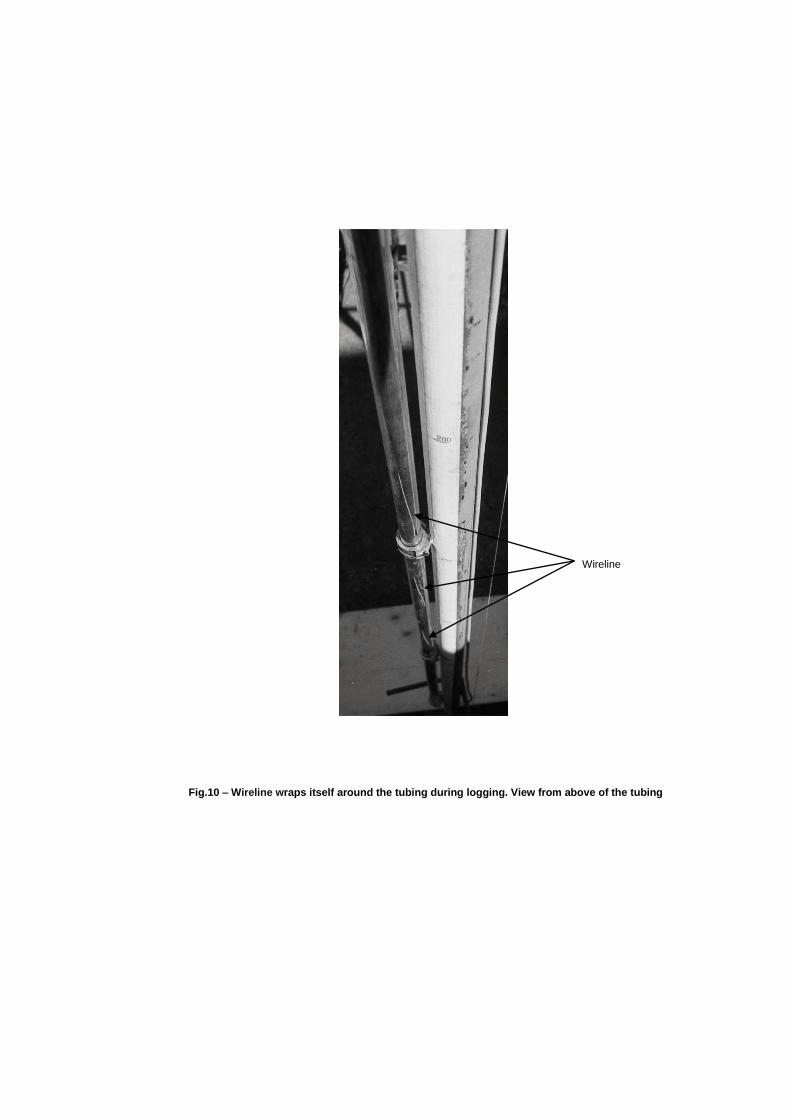
Vagapov Y.G. (1980) has studied running the logging tool through the annulus experimentally. It was
found that the wireline twists and wraps itself around the buckled tubing during logging (up to 5 times). The
photographs (Fig.6 and Fig.10) clearly illustrate the manner in which the wireline wraps itself around the
buckled tubing.
Conclusions
1. Energy source of tubing buckling in pumping wells is the pressure differential across the plunger
during upstroke.

2. Tubing buckling is accompanied by a lowering of the point of application of the weight of fluid
column inside tubing during pump upstroke. This means that the center of gravity and potential energy of system
is lowered.
3. During buckling the fluid column inside tubing moves in downward direction and does the positive
work necessary to induce buckling.
4. Positive work necessary to buckle tubing is equal to the work done by the fictitious load or
generalized force during generalized displacement.
5. Rod string is bent by the buckled tubing. Both strings are buckled during pump upstroke. This means
that the buckled sucker rod string moves inside a helically buckled tubing during pump upstroke.
6. Simultaneous buckling of tubing and rod string does not depend upon the direction of motion of the
plunger but only upon the value of the pressure drop across the plunger. In some instances, the buckled sucker
rod string moves inside the buckled tubing both upward and downward.
7. It is theoretically explained, that the rod guides may entirely prevent buckling, because the energy
source of buckling disappears after the rod guides installation. An assumption is perfectly valid for shallow to
mid-range depth rod pumping applications.
8. Simultaneous buckling of tubing and rod string can pose extreme risk of loss to logging tools during
annular production logging. To mitigate the risk of the tool loss, the walking beam must be stopped during
downstroke. During logging operation, the load on the polished rod must be monitored to predict simultaneous
buckling. Risk of the tool loss may also be minimized by sucker rod guides spaced as described in this paper.
Acknowledgment
This research article is based on the materials of our father and grandfather U.Vagapov. The authors are
grateful him for his support of this project. The authors also would like to thank the colleagues from Burintekh
company.
References
1. Adonin, A.N. 1964. Artificial Lift Processing (in Russian). Izdatelstvo NEDRA.
2. Chen, Y. C., Lin, Y. H., and Cheatham, J. B. 1990. Tubing and Casing Buckling in Horizontal Wells.
SPE J Pet Technol 42 (2): 140–141. SPE-19176-PA.
3. Dawson, R. and Paslay, P.R. 1984. Drill Pipe Buckling in Inclined Holes.J. Pet. Tech. 36 (10): 1734-
1738.
4. Gao, G. and Miska, S. 2008. Effects of Boundary Conditions and Friction on Static Buckling of Pipe
in a Horizontal Well. Presented at the IADC/SPE Drilling Conference, Orlando, Florida, 4–6 March. SPE-
111511-MS.
5. Hammack, G.W., Myers, B.D., and Barcenas, G.H. 1976. Production Logging through the Annulus
of Rod-Pumped Wells to Obtain Flow Profiles. Presented at the SPE Annual Fall Technical Conference and
Exhibition, New Orleans, Louisiana, 3-6 October. SPE-6042-MS.
6. James N.M., Rowlan O.L., Taylor C.A. and Podio A.L. 2015. Tubing Anchors Can Reduce
Production Rates and Pump Fillage. SPE Production & Operations, SPE-2014-1918491-PA.
7. Lubinski, A. and Blenkarn, K. A. 1957. Buckling of Tubing in Pumping Wells, Its Effect and Means
for Controlling It. Trans. AIME (1957) 210, 73. SPE-672-G.
8. Lubinski, A., Althouse, W.S. and Logan, J.L. 1962. Helical Buckling of Tubing Sealed in Packers. J.
Pet. Tech. 14 (6): 655-670. SPE-178-PA.
9. Lukasiewicz, S.A., Knight, C. 2006. On Lateral and Helical Buckling of a Rod in a Tubing. Journal
of Canadian Petroleum Technology. PETSOC-06-03-TN1.
10. Muravyev, I.M. and Mishchenko, I.T. 1967. Artificial Lift Systems in Other Countries (in Russian).
Izdatelstvo NEDRA.
11. Miska, S. and Cunha, J.C. 1995. An Analysis of Helical Buckling of Tubulars Subjected to Axial
and Torsional Loading in Inclined Wellbores. Presented at the SPE Production Operations Symposium,
Oklahoma City, Oklahoma, 2–4 April. SPE-29460 MS.
12. Mitchell, R.F. 1982. Buckling Behavior of Well Tubing. SPE J. 22 (05): 616–624. SPE-9264-PA.
13. Mitchell, R.F. 1995. Pull-Through Forces in Buckled Tubing. Enertech Engineering and Research
Co. SPE-26510-PA.
14. Mitchell, R.F. 2002a. Exact Analytical Solutions for Pipe Buckling in Vertical and Horizontal
Wells. SPE J. 7 (14): 373–390. SPE-72079-PA.
15. Mitchell, R.F. 2008. Tubing Buckling-The State of the Art. SPE Drill & Compl 23 (4): 361-370.
SPE-104267-PA.
16. Mitchell, R.F. 2012. Buckling of Tubing inside Casing. IADC/SPE Drilling Conference and
Exhibition, 6-8 March, San Diego, California, USA. SPE-150613-MS.
17. Nickens, H., Lea, J.F., Cox, J.C., Bhagavatula, R., and Garg, D. 2004. Downhole Beam Pump
Operation: Slippage and Buckling Forces Transmitted to the Rod String. Journal of Canadian Petroleum
Technology, PETSOC-05-05-05.
18. Paslay, P.R. and Bogy, D.B. 1964. The Stability of a Circular Rod Laterally Constrained to Be in
Contact with an Inclined Circular Cylinder. J. Appl. Mech. 31 (4): 605–610.
19. Saroyan, A.E. 1985. Tubing Strings Operation (in Russian). Izdatelstvo NEDRA.
20. Timoshenko, S. 1st Ed. 1930, 2nd Ed. 1940, 3rd Ed. 1955. Strength of Materials, Part I, Elementary
Theory and Problems, D. Van Nostrand Company.
21. Timoshenko, S. 1st Ed. 1930, 2nd Ed. 1941, 3rd Ed. 1956. Strength of Materials, Part II, Advanced
Theory and Problems, D. Van Nostrand Company.
22. Vagapov Y.G. and Sultanov, B.Z. 1980. Tubing Buckling Investigation in Sucker Rod Pumping
System (in Russian). Ufismky neftyanoy institut. Mezhvuzovsky nauchno tematichesky sbornik.
23. Vagapov S.Y. Stability of Tubing and Rod String in Pumping Wells. 2000 (in Russian). Ufimsky
gosudarstvenny neftyanoy tekhnichesky universitet.
24. Virnovski, A.S. 1971. Artificial lift Theory and Practice (in Russian). Izdatelstvo NEDRA.
25. Virnovski, A.S. and Peslyak Y.A. 1966. Buckling Of Tubing and Rod Strings (in Russian).
Izdatelstvo NEDRA.
26. Wenjun, H., Deli, G., Shaolei, W., Pengju, C. 2015. Boundary Conditions: A Key Factor in Tubular-
String Buckling. SPE-174087-PA
27. Zifeng, L. 1999. Static Buckling of Rod and Pipe String in Oil and Gas Wells. SPE-57013-MS.
Appendix A
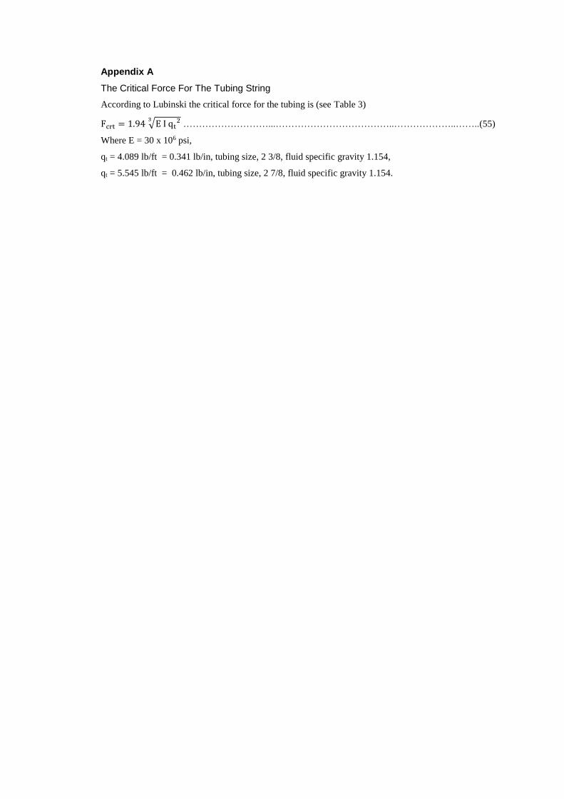
The Critical Force For The Tubing String
According to Lubinski the critical force for the tubing is (see Table 3)
Fcrt = 1.94 √E I qt23 ………………………...………………………………..………………..……..(55)
Where E = 30 x 106 psi,
qt = 4.089 lb/ft = 0.341 lb/in, tubing size, 2 3/8, fluid specific gravity 1.154,
qt = 5.545 lb/ft = 0.462 lb/in, tubing size, 2 7/8, fluid specific gravity 1.154.
Tubing
Rod
Ratio Of
Lateral
Stiffness
Radial Clearance
Between Tubing
and Rod (in)
Radial Clearance
Between Tubing
and Coupling (in)
Outside
diameter
(in)
Inside
Diameter
(in)
Moment
Of
Inertia
I t
(in4)
Outside
Diameter
(Dr )
(in)
Coupling
Outside
Diameter
(Dc)
(in)
Moment
Of
Inertia
I r,
(in4)
𝐼 2 7/8
𝐼 𝑟
𝐼 2 3/8
𝐼 𝑟
2.441
2
−𝐷𝑟
2
1.995
2
−𝐷𝑟
2
2.441
2
−𝐷𝑐
2
1.995
2
−𝐷𝑐
2
2 7/8 2.441 1.61 0.625 1.5 0.0075 215 104 0.91 0.69 0.47 0.25
2 3/8 1.995 0.78 0.75 1.625 0.0155 104 50 0.85 0.62 0.41 0.19
Table 1 – Lateral stiffness data of the rod and tubing
Tubing
Rod
Outside
Diameter
(in)
(mm)
Casing
Inside
Diameter
(in)
(mm)
Pump
Depth
(ft)
(mm)
Pump
Bore
(in)
(mm)
Maximum
Radial
Clearance
Between
Tubing
and Rod
(in)
(mm)
Maximum
Radial
Clearance
Between
Tubing and
Casing
(in)
(mm)
Tubing
Weight
With Fluid
Per Unit
Distance
(lb/in)
(kg/m)
Logging tool
Outside
Diameter
(in)
(mm)
Inside
Diameter
(in)
(mm)
Outside
Diameter
(in)
(mm)
Length
(in)
(mm)
0.925
23.50
0.488
12.40
0.047
1.20
1.417
36.0
13.6
4138
0.467
11.85
0.441
11.2
0.492
12.5
0.104
1.860
0.315
8.0
4.330
110.0
14.8
4520
0.370
9.40
0.370
9.4
2.874
73.0
Table 2 – The operational parameters of research facility
Outside Diameter (in) 2 3/8 2 7/8
Inside Diameter (in) 1.995 2.441
Critical Force (lb) 272 423
Table 3 – Critical force for the tubing
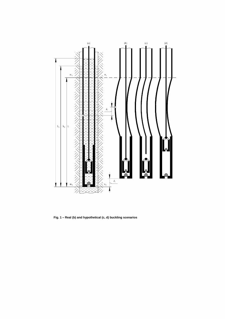
Fig. 1 – Real (b) and hypothetical (c, d) buckling scenarios
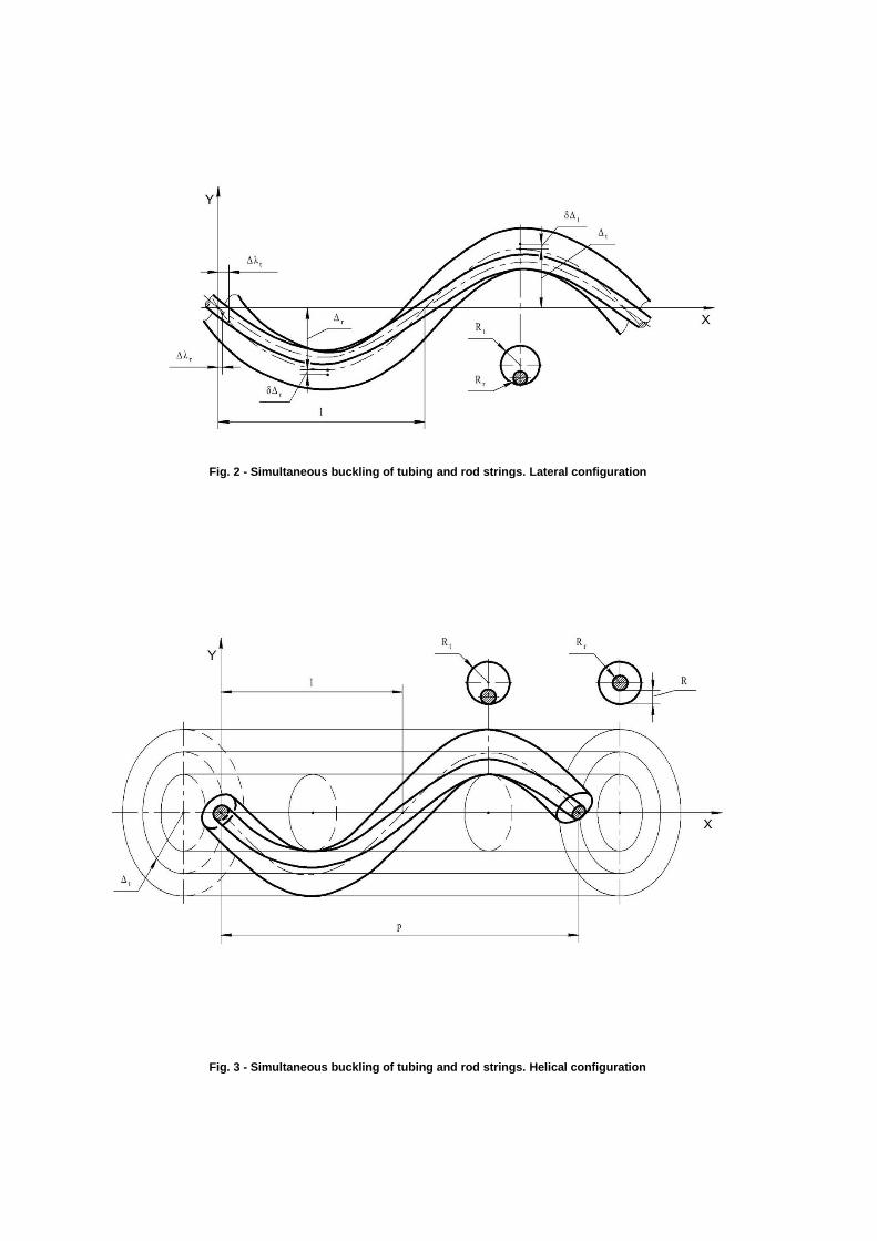
Fig. 2 - Simultaneous buckling of tubing and rod strings. Lateral configuration
Fig. 3 - Simultaneous buckling of tubing and rod strings. Helical configuration
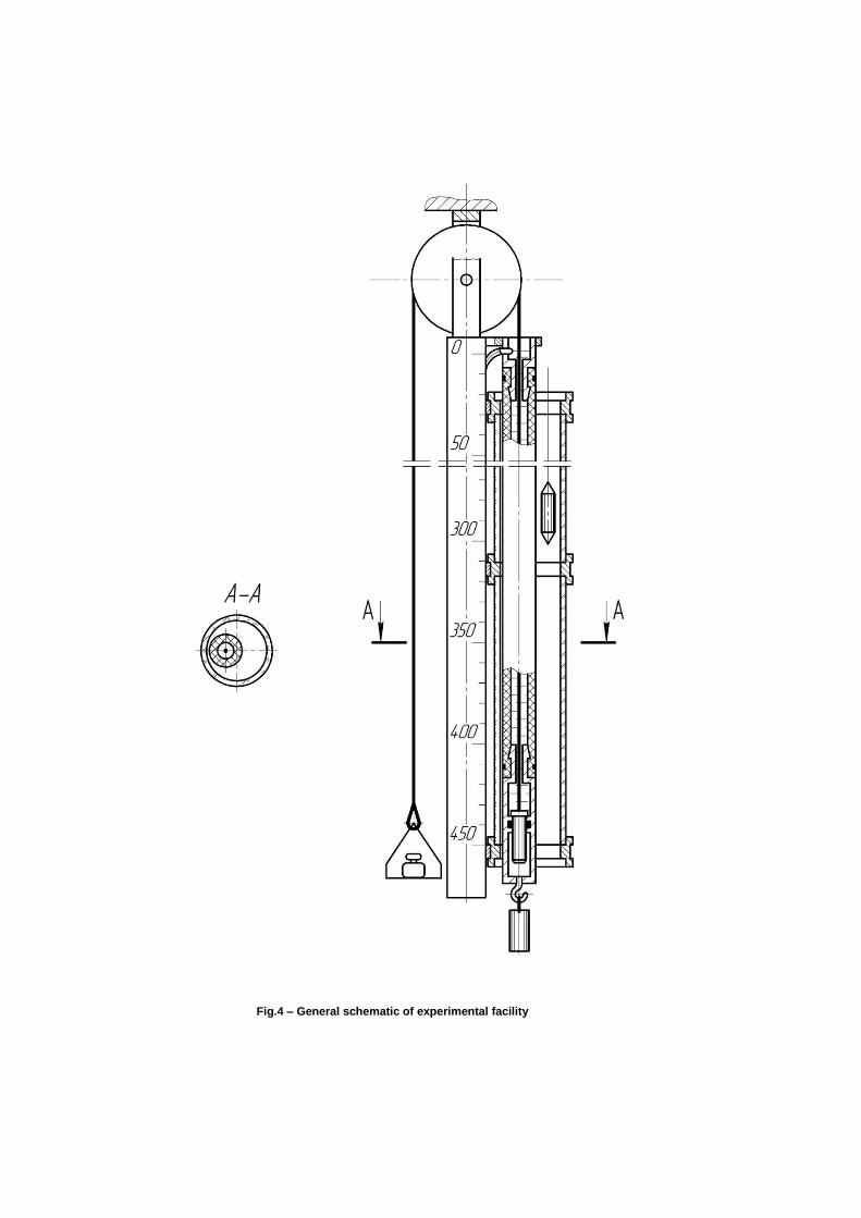
Fig.4 – General schematic of experimental facility

Tubing
Pump
100 centimeter
Lateral buckling
150 centimeter
Helical buckling 200 centimeter
Fig.5 – Simultaneous buckling of tubing and rod strings (no casing). View of portion of the buckled tubing
above the pump (left). View from above of the tubing (right)
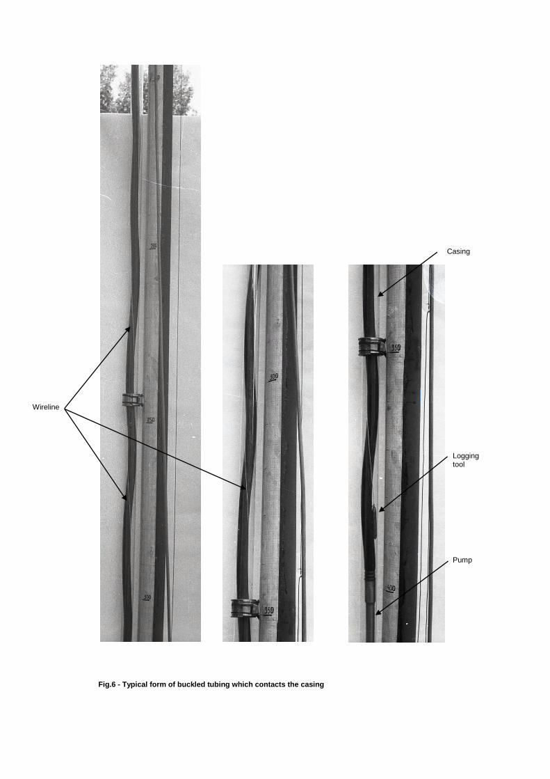
Fig.6 - Typical form of buckled tubing which contacts the casing
Wireline
Casing
Logging tool Pump
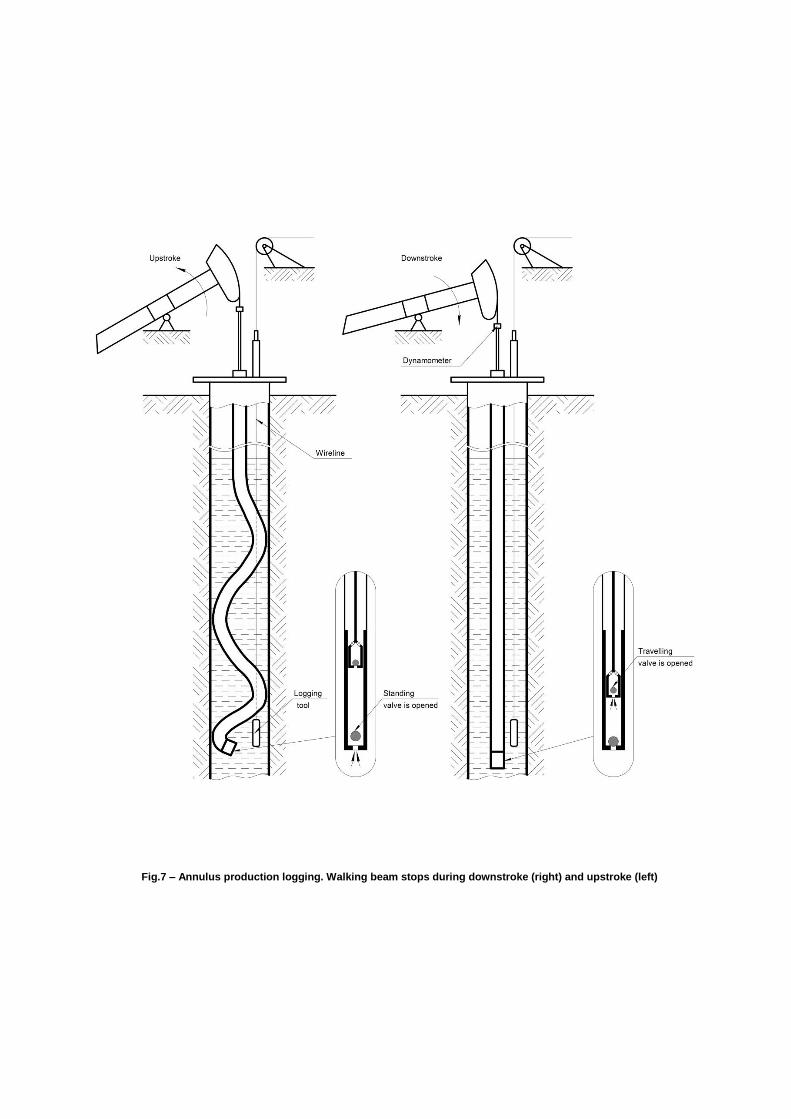
Fig.7 – Annulus production logging. Walking beam stops during downstroke (right) and upstroke (left)
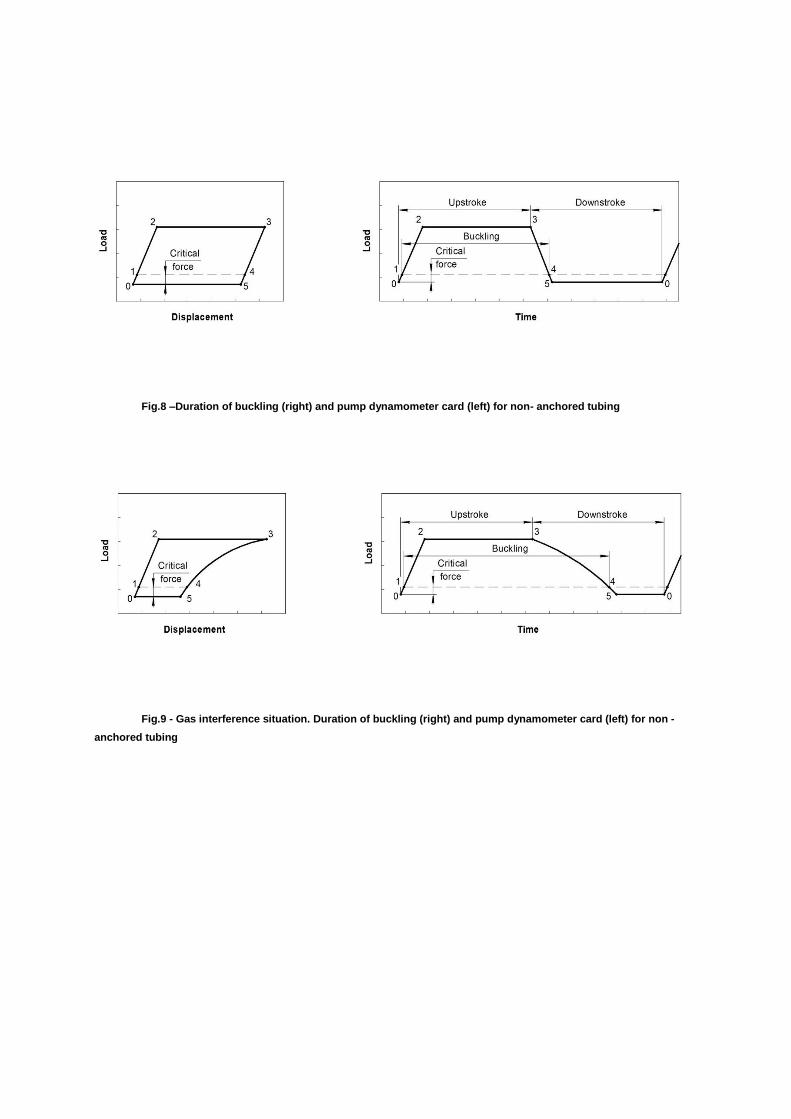
Fig.8 –Duration of buckling (right) and pump dynamometer card (left) for non- anchored tubing
Fig.9 - Gas interference situation. Duration of buckling (right) and pump dynamometer card (left) for non -
anchored tubing
Wireline
Fig.10 – Wireline wraps itself around the tubing during logging. View from above of the tubing