sinamics g120 smart accesscommissioning and/or diagnostic failure resulting from unsafe mobile...
TRANSCRIPT

___________________
___________________
___________________
___________________
___________________
___________________
___________________
___________________
SINAMICS
SINAMICS G120 Smart Access
Operating Instructions
12/2018 A5E43332487-002
Preface
Fundamental safety instructions
1
Product overview 2
Installing 3
Accessing the Web pages 4
Standard Web pages 5
Upgrading 6
Additional information 7
Siemens AG Division Digital Factory Postfach 48 48 90026 NÜRNBERG GERMANY
Ⓟ 12/2018 Subject to change
Copyright © Siemens AG 2018. All rights reserved
Legal information Warning notice system
This manual contains notices you have to observe in order to ensure your personal safety, as well as to prevent damage to property. The notices referring to your personal safety are highlighted in the manual by a safety alert symbol, notices referring only to property damage have no safety alert symbol. These notices shown below are graded according to the degree of danger.
DANGER indicates that death or severe personal injury will result if proper precautions are not taken.
WARNING indicates that death or severe personal injury may result if proper precautions are not taken.
CAUTION indicates that minor personal injury can result if proper precautions are not taken.
NOTICE indicates that property damage can result if proper precautions are not taken.
If more than one degree of danger is present, the warning notice representing the highest degree of danger will be used. A notice warning of injury to persons with a safety alert symbol may also include a warning relating to property damage.
Qualified Personnel The product/system described in this documentation may be operated only by personnel qualified for the specific task in accordance with the relevant documentation, in particular its warning notices and safety instructions. Qualified personnel are those who, based on their training and experience, are capable of identifying risks and avoiding potential hazards when working with these products/systems.
Proper use of Siemens products Note the following:
WARNING Siemens products may only be used for the applications described in the catalog and in the relevant technical documentation. If products and components from other manufacturers are used, these must be recommended or approved by Siemens. Proper transport, storage, installation, assembly, commissioning, operation and maintenance are required to ensure that the products operate safely and without any problems. The permissible ambient conditions must be complied with. The information in the relevant documentation must be observed.
Trademarks All names identified by ® are registered trademarks of Siemens AG. The remaining trademarks in this publication may be trademarks whose use by third parties for their own purposes could violate the rights of the owner.
Disclaimer of Liability We have reviewed the contents of this publication to ensure consistency with the hardware and software described. Since variance cannot be precluded entirely, we cannot guarantee full consistency. However, the information in this publication is reviewed regularly and any necessary corrections are included in subsequent editions.
SINAMICS G120 Smart Access Operating Instructions, 12/2018, A5E43332487-002 3
Preface
Product maintenance The components are subject to continuous further development within the scope of product maintenance (improvements to robustness, discontinuations of components, etc).
These further developments are "spare parts-compatible" and do not change the article number.
In the scope of such spare parts-compatible further developments, connector positions are sometimes changed slightly. This does not cause any problems with proper use of the components. Please take this fact into consideration in special installation situations (e.g. allow sufficient clearance for the cable length).
Use of third-party products This document contains recommendations relating to third-party products. Siemens accepts the fundamental suitability of these third-party products.
You can use equivalent products from other manufacturers.
Siemens does not accept any warranty for the properties of third-party products.
Compliance with the General Data Protection Regulation Siemens respects the principles of data protection, in particular the data minimization rules (privacy by design).
For this product, this means: The product does not process neither store any person-related data, only technical function data (e.g. time stamps). If the user links these data with other data (e.g. shift plans) or if he stores person-related data on the same data medium (e.g. hard disk), thus personalizing these data, he has to ensure compliance with the applicable data protection stipulations.
SINAMICS G120 Smart Access 4 Operating Instructions, 12/2018, A5E43332487-002
Table of contents
Preface ................................................................................................................................................... 3
1 Fundamental safety instructions .............................................................................................................. 6
1.1 General safety instructions ...................................................................................................... 6
1.2 Warranty and liability for application examples ........................................................................ 6
1.3 Industrial security ..................................................................................................................... 7
2 Product overview .................................................................................................................................... 8
2.1 Introduction .............................................................................................................................. 8
2.2 Layout and functions .............................................................................................................. 10
2.3 Device disposal ...................................................................................................................... 11
3 Installing ............................................................................................................................................... 12
4 Accessing the Web pages ..................................................................................................................... 14
4.1 Establishing the wireless network connection ....................................................................... 14
4.2 Accessing the Web pages ..................................................................................................... 19
5 Standard Web pages ............................................................................................................................ 20
5.1 Home page ............................................................................................................................. 20 5.1.1 Overview of the Web pages ................................................................................................... 20 5.1.2 Viewing connection status ..................................................................................................... 21
5.2 Optional settings page ........................................................................................................... 21 5.2.1 Configuring Wi-Fi ................................................................................................................... 22 5.2.2 Changing the display language .............................................................................................. 24 5.2.3 Synchronizing the time ........................................................................................................... 25 5.2.4 Upgrading ............................................................................................................................... 25 5.2.5 Viewing additional information ............................................................................................... 26 5.2.6 Configuring communication protocol ..................................................................................... 27 5.2.7 Restarting the SINAMICS G120 Smart Access ..................................................................... 28 5.2.8 Selecting quick setup mode (G120X/G120XA only) .............................................................. 29
5.3 Inverter identification .............................................................................................................. 30
5.4 Quick setup ............................................................................................................................ 31 5.4.1 Quick setup for G120X/G120XA inverters ............................................................................. 31 5.4.2 Quick setup for supported inverters ....................................................................................... 38
5.5 Parameters ............................................................................................................................. 46
5.6 JOG ........................................................................................................................................ 51
5.7 Monitoring .............................................................................................................................. 54
5.8 Diagnostics ............................................................................................................................. 54
5.9 Backup and restore ................................................................................................................ 57

Table of contents
SINAMICS G120 Smart Access Operating Instructions, 12/2018, A5E43332487-002 5
5.9.1 Backing up .............................................................................................................................. 57 5.9.2 Restoring ................................................................................................................................. 59 5.9.3 Saving as XML ........................................................................................................................ 61 5.9.4 Transferring ............................................................................................................................. 64
5.10 Support ................................................................................................................................... 66
6 Upgrading ............................................................................................................................................. 67
7 Additional information ............................................................................................................................ 70
7.1 Product information ................................................................................................................. 70
7.2 Product support ....................................................................................................................... 71
7.3 Technical specifications .......................................................................................................... 72
SINAMICS G120 Smart Access 6 Operating Instructions, 12/2018, A5E43332487-002
Fundamental safety instructions 11.1 General safety instructions
WARNING
Danger to life if the safety instructions and residual risks are not observed
If the safety instructions and residual risks in the associated hardware documentation are not observed, accidents involving severe injuries or death can occur. • Observe the safety instructions given in the hardware documentation.• Consider the residual risks for the risk evaluation.
WARNING
Malfunctions of the machine as a result of incorrect or changed parameter settings
As a result of incorrect or changed parameterization, machines can malfunction, which in turn can lead to injuries or death. • Protect the parameterization (parameter assignments) against unauthorized access.• Handle possible malfunctions by taking suitable measures, e.g. emergency stop or
emergency off.
1.2 Warranty and liability for application examples Application examples are not binding and do not claim to be complete regarding configuration, equipment or any eventuality which may arise. Application examples do not represent specific customer solutions, but are only intended to provide support for typical tasks.
As the user you yourself are responsible for ensuring that the products described are operated correctly. Application examples do not relieve you of your responsibility for safe handling when using, installing, operating and maintaining the equipment.
Fundamental safety instructions 1.3 Industrial security
SINAMICS G120 Smart Access Operating Instructions, 12/2018, A5E43332487-002 7
1.3 Industrial security
Note Industrial security
Siemens provides products and solutions with industrial security functions that support the secure operation of plants, systems, machines and networks.
In order to protect plants, systems, machines and networks against cyber threats, it is necessary to implement – and continuously maintain – a holistic, state-of-the-art industrial security concept. Siemens’ products and solutions constitute one element of such a concept.
Customers are responsible for preventing unauthorized access to their plants, systems, machines and networks. Such systems, machines and components should only be connected to an enterprise network or the Internet if and to the extent such a connection is necessary and only when appropriate security measures (e.g. firewalls and/or network segmentation) are in place.
For additional information on industrial security measures that may be implemented, please visit:
Industrial security (http://www.siemens.com/industrialsecurity)
Siemens’ products and solutions undergo continuous development to make them more secure. Siemens strongly recommends that product updates are applied as soon as they are available and that the latest product versions are used. Use of product versions that are no longer supported, and failure to apply the latest updates may increase customer’s exposure to cyber threats.
To stay informed about product updates, subscribe to the Siemens Industrial Security RSS Feed at:
Industrial security (http://www.siemens.com/industrialsecurity)
Further information is provided on the Internet:
Industrial Security Configuration Manual (https://support.industry.siemens.com/cs/ww/en/view/108862708)
WARNING
Unsafe operating states resulting from software manipulation Software manipulations (e.g. viruses, trojans, malware or worms) can cause unsafe operating states in your system that may lead to death, serious injury, and property damage. • Keep the software up to date.• Incorporate the automation and drive components into a holistic, state-of-the-art
industrial security concept for the installation or machine.• Make sure that you include all installed products into the holistic industrial security
concept.• Protect files stored on exchangeable storage media from malicious software by with
suitable protection measures, e.g. virus scanners.• Protect the drive against unauthorized changes by activating the "know-how protection"
drive function.
SINAMICS G120 Smart Access 8 Operating Instructions, 12/2018, A5E43332487-002
Product overview 22.1 Introduction
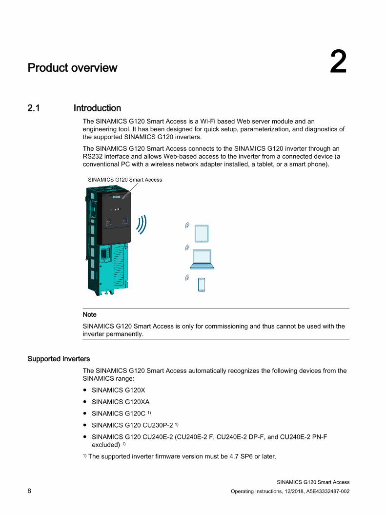
The SINAMICS G120 Smart Access is a Wi-Fi based Web server module and an engineering tool. It has been designed for quick setup, parameterization, and diagnostics of the supported SINAMICS G120 inverters.
The SINAMICS G120 Smart Access connects to the SINAMICS G120 inverter through an RS232 interface and allows Web-based access to the inverter from a connected device (a conventional PC with a wireless network adapter installed, a tablet, or a smart phone).
Note
SINAMICS G120 Smart Access is only for commissioning and thus cannot be used with the inverter permanently.
Supported inverters The SINAMICS G120 Smart Access automatically recognizes the following devices from the SINAMICS range:
● SINAMICS G120X
● SINAMICS G120XA
● SINAMICS G120C 1)
● SINAMICS G120 CU230P-2 1)
● SINAMICS G120 CU240E-2 (CU240E-2 F, CU240E-2 DP-F, and CU240E-2 PN-Fexcluded) 1)
1) The supported inverter firmware version must be 4.7 SP6 or later.
Product overview 2.1 Introduction
SINAMICS G120 Smart Access Operating Instructions, 12/2018, A5E43332487-002 9
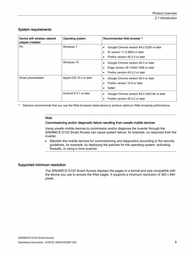
System requirements Device with wireless network adapter installed
Operating system Recommended Web browser 1)
PC Windows 7 • Google Chrome version 64.0.3239 or later • IE version 11.0.9600 or later • Firefox version 45.0.2 or later
Windows 10 • Google Chrome version 65.0 or later • Edge version 38.14393.1066 or later • Firefox version 45.0.2 or later
Smart phone/tablet Apple iOS 10.2 or later • Google Chrome version 65.0 or later • Firefox version 10.6 or later • Safari
Android 6.0.1 or later • Google Chrome version 64.0.3202.84 or later • Firefox version 45.0.2 or later
1) Siemens recommends that you use the Web browsers listed above to achieve optimum Web browsing performance.
Note Commissioning and/or diagnostic failure resulting from unsafe mobile devices
Using unsafe mobile devices to commission and/or diagnose the inverter through the SINAMICS G120 Smart Access can cause system failure, for example, no response from the inverter. • Maintain the mobile devices for commissioning and diagnostics according to the security
guidelines, for example, by deploying the patches for the operating system, activating firewalls, or using a virus scanner.
Supported minimum resolution The SINAMICS G120 Smart Access displays the pages in a format and size compatible with the device you use to access the Web pages. It supports a minimum resolution of 360 x 640 pixels.

Product overview 2.2 Layout and functions
SINAMICS G120 Smart Access 10 Operating Instructions, 12/2018, A5E43332487-002
2.2 Layout and functions
Layout
Button functions Button Function Reset • Holding down the button for more than three seconds when the SINAMICS G120 Smart Access is in
power-on state resets the Wi-Fi configuration of the SINAMICS G120 Smart Access to factory defaults. • Holding down the button when the SINAMICS G120 Smart Access is in power-off state and powering on
the module enters basic upgrading mode.
WLAN Holding down the button for more than three seconds enables/disables the Wi-Fi connection of the SINAMICS G120 Smart Access.
LED status LED Color Description Inverter com-munication
Solid red The communication between the module and the inverter is not established. Solid green The communication between the module and the inverter is established.
Wi-Fi commu-nication
Solid red The network communication is initializing. Solid yellow The network initialization completes but the module is not connected to a PC or
mobile device. Solid green The connection between the module and the PC or mobile device is set up and you
can open the Web pages now. Flashing green The connection between the module and the PC or mobile device is set up and the
Web page is open. Flashing yellow The module requires a restart because an upgrade is completed or the Wi-Fi config-
uration is modified. Alternating flashing red and yellow
The module is upgrading.

Product overview 2.3 Device disposal
SINAMICS G120 Smart Access Operating Instructions, 12/2018, A5E43332487-002 11
2.3 Device disposal
Recycling and disposal
For environmentally-friendly recycling and disposal of your old device, please contact a company certified for the disposal of waste electrical and electronic equipment, and dispose of the old device as prescribed in the respective country of use.
SINAMICS G120 Smart Access 12 Operating Instructions, 12/2018, A5E43332487-002
Installing 3
Note SINAMICS G120 Smart Access power supply
The SINAMICS G120 Smart Access has no internal power supply and derives its power directly from the inverter through the RS232 interface. Any configuration data stored on the SINAMICS G120 Smart Access is saved to its memory which does not require power to retain the data.
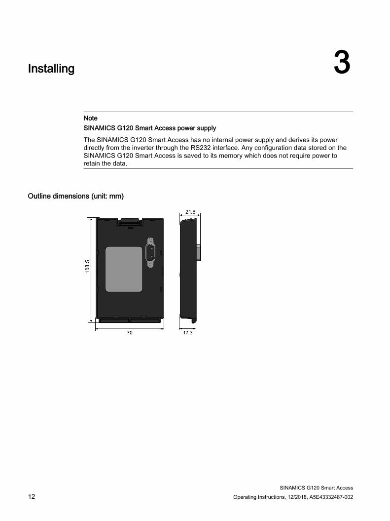
Outline dimensions (unit: mm)
Installing
SINAMICS G120 Smart Access Operating Instructions, 12/2018, A5E43332487-002 13
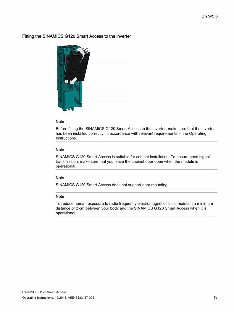
Fitting the SINAMICS G120 Smart Access to the inverter
Note
Before fitting the SINAMICS G120 Smart Access to the inverter, make sure that the inverter has been installed correctly, in accordance with relevant requirements in the Operating Instructions.
Note
SINAMICS G120 Smart Access is suitable for cabinet installation. To ensure good signal transmission, make sure that you leave the cabinet door open when the module is operational.
Note
SINAMICS G120 Smart Access does not support door mounting.
Note
To reduce human exposure to radio frequency electromagnetic fields, maintain a minimum distance of 2 cm between your body and the SINAMICS G120 Smart Access when it is operational.
SINAMICS G120 Smart Access 14 Operating Instructions, 12/2018, A5E43332487-002
Accessing the Web pages 4You can access the SINAMICS G120 Web pages from a PC or a mobile device that connects to the SINAMICS G120 Smart Access.
4.1 Establishing the wireless network connection
NOTICE
Equipment malfunctions as a result of unauthorized access to the inverter
Hacker attack can result in unauthorized access to the inverter through the SINAMICS G120 Smart Access. This can cause equipment malfunctions. • Before logging on to the SINAMICS G120 Web pages, make sure that there is no
network security risk.– If the Wi-Fi communication LED lights solid green or flashes green, make sure that
no unauthorized access to the inverter exists.– If an unauthorized access to the inverter does exist, remove the SINAMICS G120
Smart Access, and then fit it to the inverter again. Then power on the SINAMICSG120 Smart Access to re-establish the wireless network connection.
SINAMICS G120 Web site ● http://192.168.1.1
● https://192.168.1.1 (requires download and installation of SSL certificates)
Establishing initial wireless network connection 1. After you have fitted the SINAMICS G120 Smart Access to the inverter, power on the
inverter and then hold down the WLAN button (> 3 s) to enable the Wi-Fi connection ofthe module.
2. Activate the Wi-Fi interface inside your PC or mobile device. If you desire to establish thewireless network connection on your PC, make sure that you have previously enabled theautomatic IP settings.
3. Search the wireless network SSID of the SINAMICS G120 Smart Access: G120 smartaccess_xxxxxx ("xxxxxx" stands for the last six characters of the module MAC address ofthe SINAMICS G120 Smart Access.).
4. Enter the wireless network password to launch the connection (default password:12345678).
Accessing the Web pages 4.1 Establishing the wireless network connection
SINAMICS G120 Smart Access Operating Instructions, 12/2018, A5E43332487-002 15
5. Enter the SINAMICS G120 Web site (http://192.168.1.1 or https://192.168.1.1) in the supported browser.
Note
After the establishment of the wireless network connection for the first time, it may take some time for the Web browser to open the SINAMICS G120 Web page.
Note
When you use https:// to access the SINAMICS G120 Web page, if you see an error message prompting that your connection is not private because the security certificate is not trusted by your device's operating system, ignore it and proceed with the Web page access.
Note
After opening the SINAMICS G120 Web page with https:// in Windows 10, if you see the message “certificate error”, ignore it and proceed with the Web page access.
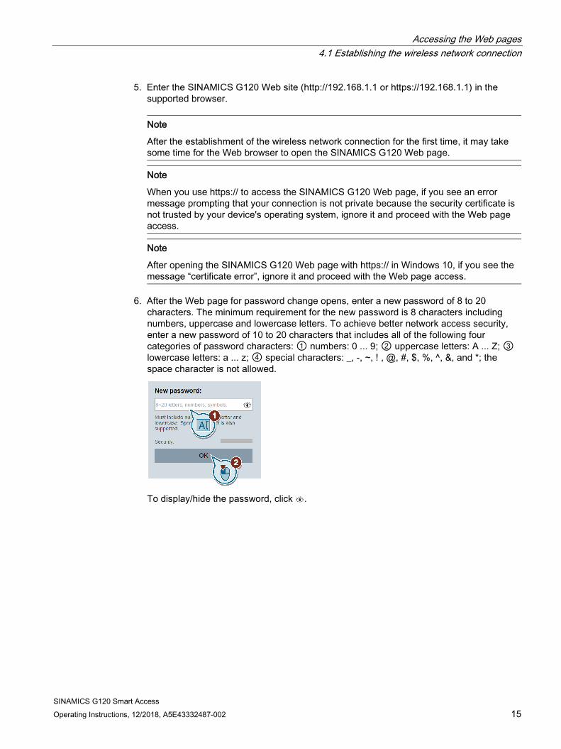
6. After the Web page for password change opens, enter a new password of 8 to 20 characters. The minimum requirement for the new password is 8 characters including numbers, uppercase and lowercase letters. To achieve better network access security, enter a new password of 10 to 20 characters that includes all of the following four categories of password characters: ① numbers: 0 ... 9; ② uppercase letters: A ... Z; ③ lowercase letters: a ... z; ④ special characters: _, -, ~, ! , @, #, $, %, ^, &, and *; the space character is not allowed.
To display/hide the password, click .
Accessing the Web pages 4.1 Establishing the wireless network connection
SINAMICS G120 Smart Access 16 Operating Instructions, 12/2018, A5E43332487-002
Note that this password change page includes a security level indicator. The indicator uses different colors to indicate the security strength of your current password. For detailed information, see the table below:
Password security level Description
Low The password includes 8 or 9 characters and is a mixture of numbers, uppercase and lowercase letters.
Medium The password meets one of the following two requirements: • The password includes 10 to 20 characters and is a mixture of
numbers, uppercase and lowercase letters. • The password includes 8 or 9 characters and is a mixture of num-
bers, uppercase and lowercase letters, and special characters.
High The password contains 10 to 20 characters and is a mixture of num-bers, uppercase letters, lowercase letters, and special characters.
After your confirmation of the new password entry, the module restarts automatically.
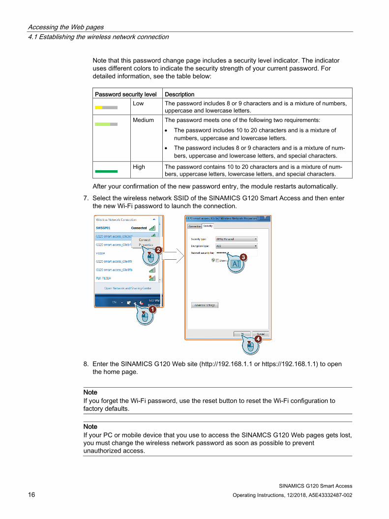
7. Select the wireless network SSID of the SINAMICS G120 Smart Access and then enter the new Wi-Fi password to launch the connection.
8. Enter the SINAMICS G120 Web site (http://192.168.1.1 or https://192.168.1.1) to open
the home page.
Note If you forget the Wi-Fi password, use the reset button to reset the Wi-Fi configuration to factory defaults.
Note If your PC or mobile device that you use to access the SINAMCS G120 Web pages gets lost, you must change the wireless network password as soon as possible to prevent unauthorized access.
Accessing the Web pages 4.1 Establishing the wireless network connection
SINAMICS G120 Smart Access Operating Instructions, 12/2018, A5E43332487-002 17
Installing SSL certificates (only for access with https://) To access the SINAMICS G120 Web pages with https:// from a Windows 10-based PC or iOS-based mobile devices, you need to install SSL certificates.
Installing on Windows 10-based PCs
1. Enter the certificate download Web site (https://support.industry.siemens.com/cs/ww/en/ps/13225/dl) and download "G120 smart access certificates.zip". Extract the certificate file "root-ca-cert.der" to your local drive.
2. Double-click the file “root-ca-cert.der” and then select “Install certificate > Next” to open the certificate store.
3. Select “Places all certificates in the following store” and then browse to “Trusted Root Certification Authorities”.
4. Select "OK > Next > Finish" to complete the certificate installation. Now you are able to access the SINAMICS G120 Web pages via the SINAMICS G120 Smart Access.
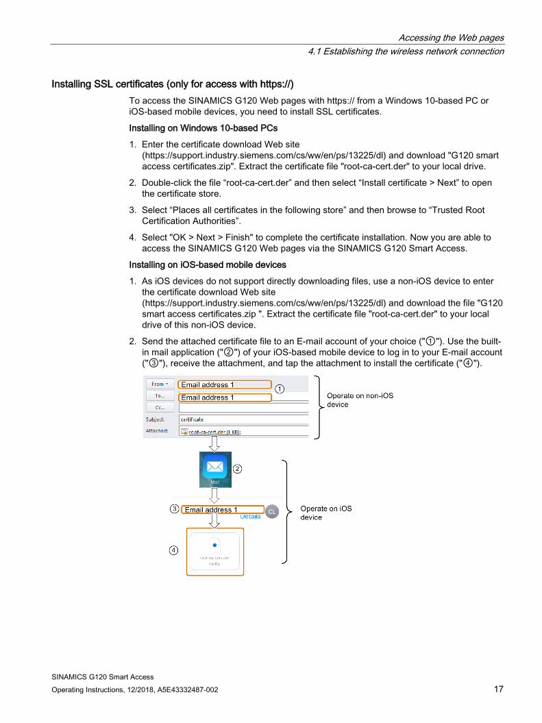
Installing on iOS-based mobile devices
1. As iOS devices do not support directly downloading files, use a non-iOS device to enter the certificate download Web site (https://support.industry.siemens.com/cs/ww/en/ps/13225/dl) and download the file "G120 smart access certificates.zip ". Extract the certificate file "root-ca-cert.der" to your local drive of this non-iOS device.
2. Send the attached certificate file to an E-mail account of your choice ("①"). Use the built-in mail application ("②") of your iOS-based mobile device to log in to your E-mail account ("③"), receive the attachment, and tap the attachment to install the certificate ("④").

Accessing the Web pages 4.1 Establishing the wireless network connection
SINAMICS G120 Smart Access 18 Operating Instructions, 12/2018, A5E43332487-002
3. Select "Settings > General > Profiles" to view configuration profiles in your mobile device and make sure that the certificate has been issued to "G120 Smart Access 2018".
4. Select "Settings > General > About > Certificate Trust Settings" to enable full trust for the
root certificate "G120 Smart Access 2018". Now you are able to access the SINAMICS G120 Web pages via the SINAMICS G120 Smart Access.
Accessing the Web pages 4.2 Accessing the Web pages
SINAMICS G120 Smart Access Operating Instructions, 12/2018, A5E43332487-002 19
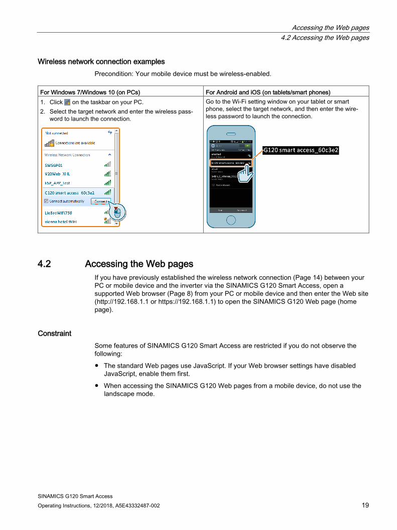
Wireless network connection examples Precondition: Your mobile device must be wireless-enabled.
For Windows 7/Windows 10 (on PCs) For Android and iOS (on tablets/smart phones) 1. Click on the taskbar on your PC. 2. Select the target network and enter the wireless pass-
word to launch the connection.
Go to the Wi-Fi setting window on your tablet or smart phone, select the target network, and then enter the wire-less password to launch the connection.
4.2 Accessing the Web pages If you have previously established the wireless network connection (Page 14) between your PC or mobile device and the inverter via the SINAMICS G120 Smart Access, open a supported Web browser (Page 8) from your PC or mobile device and then enter the Web site (http://192.168.1.1 or https://192.168.1.1) to open the SINAMICS G120 Web page (home page).
Constraint Some features of SINAMICS G120 Smart Access are restricted if you do not observe the following:
● The standard Web pages use JavaScript. If your Web browser settings have disabled JavaScript, enable them first.
● When accessing the SINAMICS G120 Web pages from a mobile device, do not use the landscape mode.

SINAMICS G120 Smart Access 20 Operating Instructions, 12/2018, A5E43332487-002
Standard Web pages 5 5.1 Home page
5.1.1 Overview of the Web pages
Web page header area
① Connection status indication (Page 21)
② Connected inverter (Page 30)
③ Fault/alarm indication (Page 54)
④ Navigation sidebar (visible only on lower-level pages)
⑤ Advancing backward (visible only on lower-level pages)
Web page body
⑥ Quick setup (Page 38)
⑦ Parameter settings (Page 46)
⑧ Motor test run in JOG/HAND mode (Page 51)
⑨ Inverter status monitoring (Page 54)
⑩ Diagnostics (Page 54)
⑪ Backup and restore (Page 57)
Web page footer area
⑫ Optional Web access settings (Page 21)
⑬ Inverter data identification (Page 30)
⑭ Support information (Page 66)
Note
The Web page illustrations from this chapter forward represent only the standard PC Web page appearance.

Standard Web pages 5.2 Optional settings page
SINAMICS G120 Smart Access Operating Instructions, 12/2018, A5E43332487-002 21
5.1.2 Viewing connection status You can view the connection status in the upper-left corner of the Web pages. Icon Status Description
Connected Communication between the PC/mobile device and the inverter is established.
Note that the green status icon indicates one of the following inverter states (see r0002): • Inverter is in normal operation • Inverter is ready for operation • Inverter is ready for switching on • Inverter switching-on is inhibited • Inverter is initializing • Inverter is waiting for booting/partial booting
Disconnected Communication between the PC/mobile device and the inverter is not estab-
lished.
5.2 Optional settings page You can make the following optional Web access settings: ● Establishing the wireless network connection (Page 14) ● Changing the display language (Page 24) ● Synchronizing the time (Page 25) ● Upgrading (Page 25) ● Viewing additional information (Page 26) ● Configuring communication protocol (Page 27) ● Restarting the SINAMICS G120 Smart Access (Page 28) ● Selecting quick setup mode (G120X/G120XA only) (Page 29)
Standard Web pages 5.2 Optional settings page
SINAMICS G120 Smart Access 22 Operating Instructions, 12/2018, A5E43332487-002
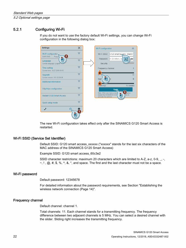
5.2.1 Configuring Wi-Fi If you do not want to use the factory default Wi-Fi settings, you can change Wi-Fi configuration in the following dialog box:
The new Wi-Fi configuration takes effect only after the SINAMICS G120 Smart Access is restarted.
Wi-Fi SSID (Service Set Identifier) Default SSID: G120 smart access_xxxxxx ("xxxxxx" stands for the last six characters of the MAC address of the SINAMICS G120 Smart Access)
Example SSID: G120 smart access_60c3e2
SSID character restrictions: maximum 20 characters which are limited to A-Z, a-z, 0-9, _, -, ~, ! , @, #, $, %, ^, &, *, and space. The first and the last character must not be a space.
Wi-Fi password Default password: 12345678
For detailed information about the password requirements, see Section "Establishing the wireless network connection (Page 14)".
Frequency channel Default channel: channel 1.
Total channels: 11. Each channel stands for a transmitting frequency. The frequency difference between two adjacent channels is 5 MHz. You can select a desired channel with the slider. Sliding right increases the transmitting frequency.
Standard Web pages 5.2 Optional settings page
SINAMICS G120 Smart Access Operating Instructions, 12/2018, A5E43332487-002 23
Signal strength Default signal strength: 0 (strong)
The wireless network signal transmission distance may vary with environmental conditions. When selecting the desired signal strength, consider both the acceptable signal transmission distance and the corresponding wireless network security. You can select a desired strength with the slider.
Resetting Wi-Fi configuration When the SINAMICS G120 Smart Access is in power-on state, holding down the reset button for more than three seconds resets the Wi-Fi configuration of the SINAMICS G120 Smart Access to factory defaults. Description Factory defaults Wi-Fi name G120 smart access_xxxxxx Wi-Fi password 12345678 Wi-Fi frequency channel 1 Communication protocol http enabled
Note
Before pressing the reset button to reset the Wi-Fi configuration, make sure that the Wi-Fi communication LED on the SINAMICS G120 Smart Access lights up solid green/solid yellow or flashes green. The Wi-Fi configuration is reset successfully when the status of the Wi-Fi communication LED flashes yellow. After resetting Wi-Fi configuration, restart SINAMICS G120 Smart Access.

Standard Web pages 5.2 Optional settings page
SINAMICS G120 Smart Access 24 Operating Instructions, 12/2018, A5E43332487-002
5.2.2 Changing the display language The SINAMICS G120 Web pages support the following user interface languages: English (default), Chinese, German, Italian, Spanish, and French. Proceed as follows to select the desired language:

Standard Web pages 5.2 Optional settings page
SINAMICS G120 Smart Access Operating Instructions, 12/2018, A5E43332487-002 25
5.2.3 Synchronizing the time When the connection between the inverter and the PC/mobile device is established, the Web page can display the current time and date information of the connected PC/mobile device (see below). You can enable time synchronization between the inverter and the connected PC/mobile device to record the occurrence time of inverter faults/alarms. After you enable synchronization, the inverter receives the time of the day from the connected PC/mobile device.
Note
Only SINAMICS G120 CU230P-2, SINAMICS G120X and SINAMICS G120XA support this function.
5.2.4 Upgrading Upgrading includes conventional upgrading and basic upgrading. For detailed information, see Section "Upgrading (Page 67)".

Standard Web pages 5.2 Optional settings page
SINAMICS G120 Smart Access 26 Operating Instructions, 12/2018, A5E43332487-002
5.2.5 Viewing additional information The following window provides additional information about the SINAMICS G120 Smart Access:
Standard Web pages 5.2 Optional settings page
SINAMICS G120 Smart Access Operating Instructions, 12/2018, A5E43332487-002 27
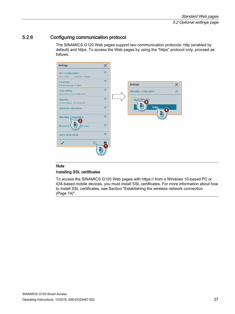
5.2.6 Configuring communication protocol The SINAMICS G120 Web pages support two communication protocols: http (enabled by default) and https. To access the Web pages by using the "https" protocol only, proceed as follows:
Note Installing SSL certificates
To access the SINAMICS G120 Web pages with https:// from a Windows 10-based PC or iOS-based mobile devices, you must install SSL certificates. For more information about how to install SSL certificates, see Section "Establishing the wireless network connection (Page 14)".
Standard Web pages 5.2 Optional settings page
SINAMICS G120 Smart Access 28 Operating Instructions, 12/2018, A5E43332487-002
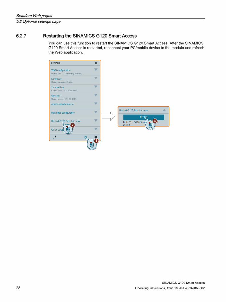
5.2.7 Restarting the SINAMICS G120 Smart Access You can use this function to restart the SINAMICS G120 Smart Access. After the SINAMICS G120 Smart Access is restarted, reconnect your PC/mobile device to the module and refresh the Web application.
Standard Web pages 5.2 Optional settings page
SINAMICS G120 Smart Access Operating Instructions, 12/2018, A5E43332487-002 29
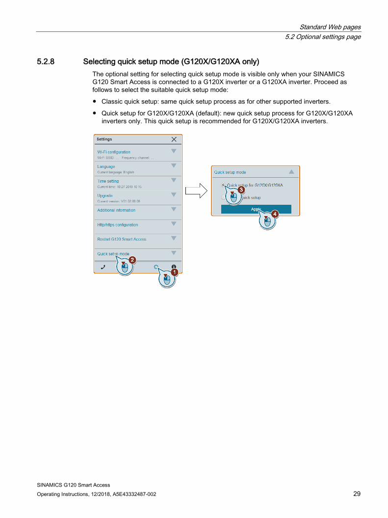
5.2.8 Selecting quick setup mode (G120X/G120XA only) The optional setting for selecting quick setup mode is visible only when your SINAMICS G120 Smart Access is connected to a G120X inverter or a G120XA inverter. Proceed as follows to select the suitable quick setup mode:
● Classic quick setup: same quick setup process as for other supported inverters.
● Quick setup for G120X/G120XA (default): new quick setup process for G120X/G120XA inverters only. This quick setup is recommended for G120X/G120XA inverters.

Standard Web pages 5.3 Inverter identification
SINAMICS G120 Smart Access 30 Operating Instructions, 12/2018, A5E43332487-002
5.3 Inverter identification The inverter identification Web page displays detailed information of the currently connected inverter:
Note
For G120X and G120XA inverters, the inverter identification Web page will not display the Control Unit article number and the Control Unit serial number.
Note
For G120C inverters, the inverter identification Web page will not display information about Power Module.
Standard Web pages 5.4 Quick setup
SINAMICS G120 Smart Access Operating Instructions, 12/2018, A5E43332487-002 31
5.4 Quick setup The quick setup Web page allows you to set the application class, motor data, I/O configuration, important parameters, and motor identification of the supported inverter.
5.4.1 Quick setup for G120X/G120XA inverters
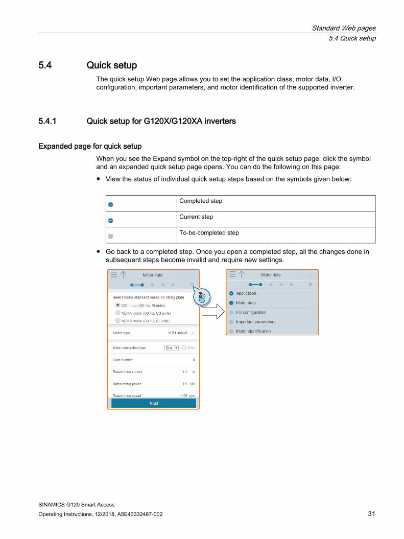
Expanded page for quick setup When you see the Expand symbol on the top-right of the quick setup page, click the symbol and an expanded quick setup page opens. You can do the following on this page:
● View the status of individual quick setup steps based on the symbols given below:
Completed step
Current step
To-be-completed step
● Go back to a completed step. Once you open a completed step, all the changes done in subsequent steps become invalid and require new settings.
Standard Web pages 5.4 Quick setup
SINAMICS G120 Smart Access 32 Operating Instructions, 12/2018, A5E43332487-002
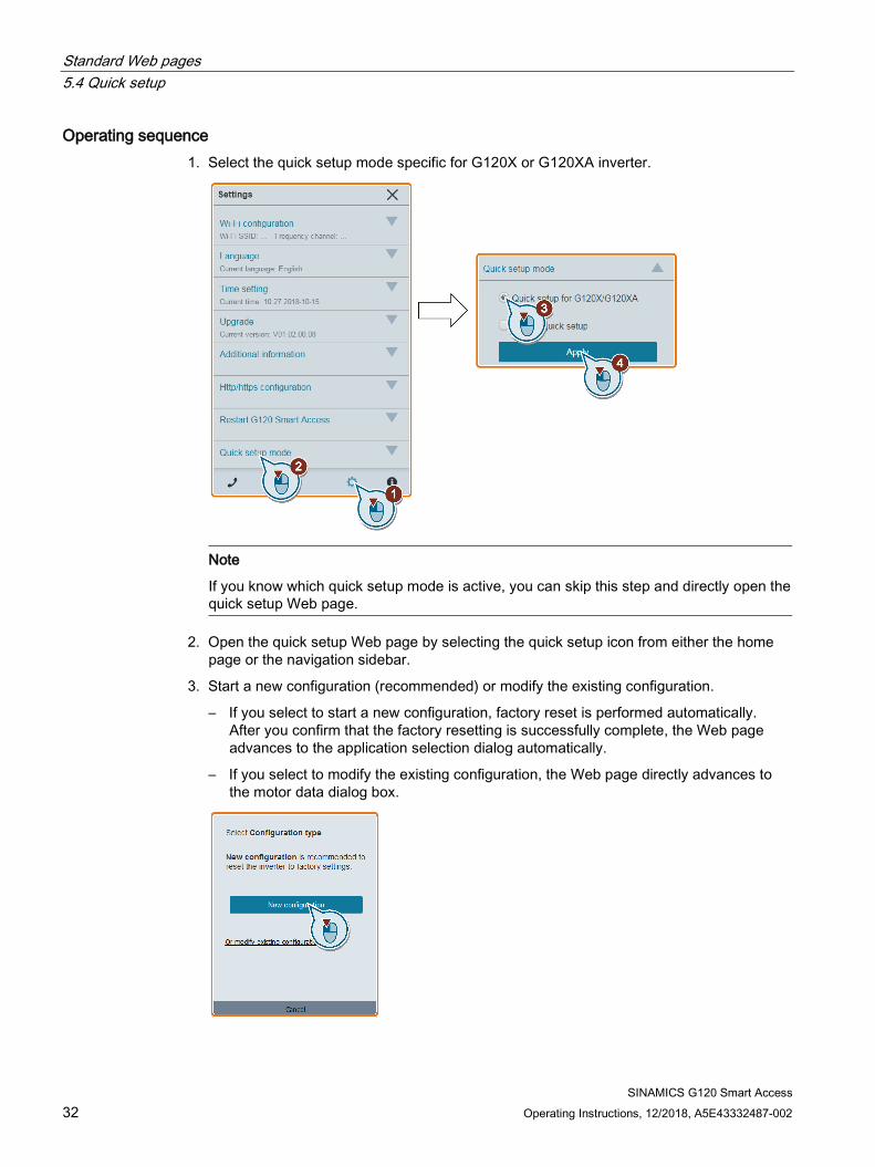
Operating sequence 1. Select the quick setup mode specific for G120X or G120XA inverter.
Note
If you know which quick setup mode is active, you can skip this step and directly open the quick setup Web page.
2. Open the quick setup Web page by selecting the quick setup icon from either the home page or the navigation sidebar.
3. Start a new configuration (recommended) or modify the existing configuration.
– If you select to start a new configuration, factory reset is performed automatically. After you confirm that the factory resetting is successfully complete, the Web page advances to the application selection dialog automatically.
– If you select to modify the existing configuration, the Web page directly advances to the motor data dialog box.
Standard Web pages 5.4 Quick setup
SINAMICS G120 Smart Access Operating Instructions, 12/2018, A5E43332487-002 33
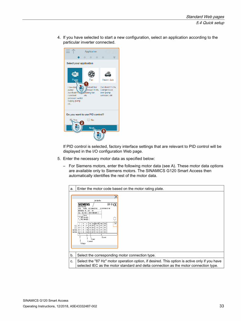
4. If you have selected to start a new configuration, select an application according to the particular inverter connected.
If PID control is selected, factory interface settings that are relevant to PID control will be displayed in the I/O configuration Web page.
5. Enter the necessary motor data as specified below:
– For Siemens motors, enter the following motor data (see A). These motor data options are available only to Siemens motors. The SINAMICS G120 Smart Access then automatically identifies the rest of the motor data.
a. Enter the motor code based on the motor rating plate.
b. Select the corresponding motor connection type. c. Select the "87 Hz" motor operation option, if desired. This option is active only if you have
selected IEC as the motor standard and delta connection as the motor connection type.

Standard Web pages 5.4 Quick setup
SINAMICS G120 Smart Access 34 Operating Instructions, 12/2018, A5E43332487-002
– For the rest of the motors, you must manually enter all necessary motor data (see B).
Standard Web pages 5.4 Quick setup
SINAMICS G120 Smart Access Operating Instructions, 12/2018, A5E43332487-002 35
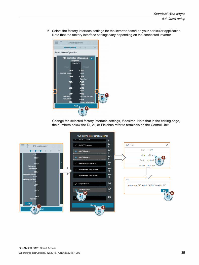
6. Select the factory interface settings for the inverter based on your particular application. Note that the factory interface settings vary depending on the connected inverter.
Change the selected factory interface settings, if desired. Note that in the editing page, the numbers below the DI, AI, or Fieldbus refer to terminals on the Control Unit.
Standard Web pages 5.4 Quick setup
SINAMICS G120 Smart Access 36 Operating Instructions, 12/2018, A5E43332487-002
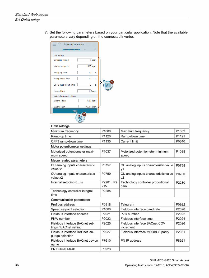
7. Set the following parameters based on your particular application. Note that the available parameters vary depending on the connected inverter.
Limit settings Minimum frequency P1080 Maximum frequency P1082 Ramp-up time P1120 Ramp-down time P1121 OFF3 ramp-down time P1135 Current limit P0640 Motor potentiometer settings Motorized potentiometer maxi-mum speed
P1037 Motorized potentiometer minimum speed
P1038
Macro related parameters CU analog inputs characteristic value x1
P0757 CU analog inputs characteristic value y1
P0758
CU analog inputs characteristic value x2
P0759 CU analog inputs characteristic value y2
P0760
Internal setpoint (0...n) P2201...P2215
Technology controller proportional gain
P2280
Technology controller integral time
P2285
Communication parameters Profibus address P0918 Telegram P0922 Speed setpoint selection P1000 Fieldbus interface baud rate P2020 Fieldbus interface address P2021 PZD number P2022 PKW number P2023 Fieldbus interface time P2024 Fieldbus interface BACnet set-tings / BACnet setting
P2025 Fieldbus interface BACnet COV increment
P2026
Fieldbus interface BACnet lan-guage selection
P2027 Fieldbus interface MODBUS parity P2031
Fieldbus interface BACnet device name
P7610 PN IP address P8921
PN Subnet Mask P8923

Standard Web pages 5.4 Quick setup
SINAMICS G120 Smart Access Operating Instructions, 12/2018, A5E43332487-002 37
8. Select the method which the inverter uses to measure the data of the connected motor.
9. Complete quick setup.
Standard Web pages 5.4 Quick setup
SINAMICS G120 Smart Access 38 Operating Instructions, 12/2018, A5E43332487-002
5.4.2 Quick setup for supported inverters
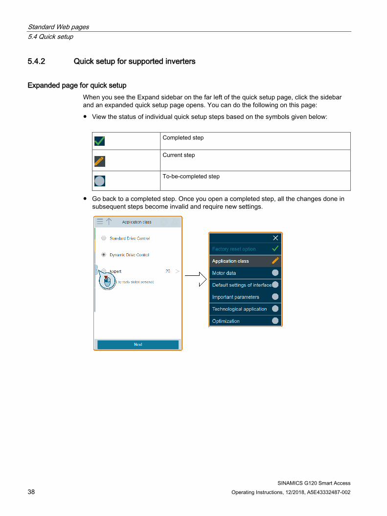
Expanded page for quick setup When you see the Expand sidebar on the far left of the quick setup page, click the sidebar and an expanded quick setup page opens. You can do the following on this page:
● View the status of individual quick setup steps based on the symbols given below:
Completed step
Current step
To-be-completed step
● Go back to a completed step. Once you open a completed step, all the changes done insubsequent steps become invalid and require new settings.

Standard Web pages 5.4 Quick setup
SINAMICS G120 Smart Access Operating Instructions, 12/2018, A5E43332487-002 39
Operating sequence 1. Open the quick setup Web page by selecting the quick setup icon from either the home
page or the navigation sidebar.
Note
For G120X/G120XA inverters, if you want to use this quick setup mode, you must select "classical quick setup" first. For more information about selecting quick setup mode, see section "Selecting quick setup mode (G120X/G120XA only) (Page 29)".
2. Reset to factory settings (recommended) or modify existing settings.
3. Select an application class according to the particular inverter connected. If required, clickrelevant application class to expand the detailed description.
If "Expert" is selected, you can select your control mode of the inverter.

Standard Web pages 5.4 Quick setup
SINAMICS G120 Smart Access 40 Operating Instructions, 12/2018, A5E43332487-002
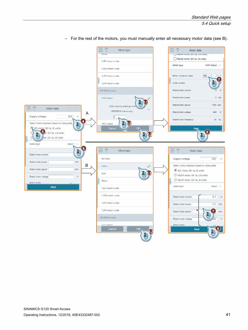
4. Enter the necessary motor data as specified below:
– For Siemens motors, enter the following motor data (see A). These motor data options are available only to Siemens motors. The SINAMICS G120 Smart Access then automatically identifies the rest of the motor data.
a. Enter the motor code based on the motor rating plate.
b. Select the corresponding motor connection type. c. Select the "87 Hz" motor operation option, if desired. This option is active only if you
have selected IEC as the motor standard and delta connection as the motor connection type.
Standard Web pages 5.4 Quick setup
SINAMICS G120 Smart Access Operating Instructions, 12/2018, A5E43332487-002 41
– For the rest of the motors, you must manually enter all necessary motor data (see B).

Standard Web pages 5.4 Quick setup
SINAMICS G120 Smart Access 42 Operating Instructions, 12/2018, A5E43332487-002
5. Select the factory interface settings for the inverter based on your particular application. Note that the factory interface settings vary depending on the connected inverter.
Standard Web pages 5.4 Quick setup
SINAMICS G120 Smart Access Operating Instructions, 12/2018, A5E43332487-002 43
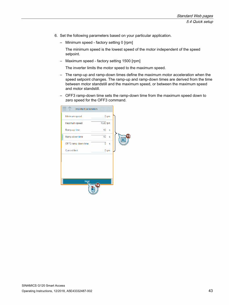
6. Set the following parameters based on your particular application.
– Minimum speed - factory setting 0 [rpm]
The minimum speed is the lowest speed of the motor independent of the speed setpoint.
– Maximum speed - factory setting 1500 [rpm]
The inverter limits the motor speed to the maximum speed.
– The ramp-up and ramp-down times define the maximum motor acceleration when the speed setpoint changes. The ramp-up and ramp-down times are derived from the time between motor standstill and the maximum speed, or between the maximum speed and motor standstill.
– OFF3 ramp-down time sets the ramp-down time from the maximum speed down to zero speed for the OFF3 command.

Standard Web pages 5.4 Quick setup
SINAMICS G120 Smart Access 44 Operating Instructions, 12/2018, A5E43332487-002
7. Select the desired technological application. Depending on the selected application class, the technological application list deviates from the list below:
Standard Web pages 5.4 Quick setup
SINAMICS G120 Smart Access Operating Instructions, 12/2018, A5E43332487-002 45
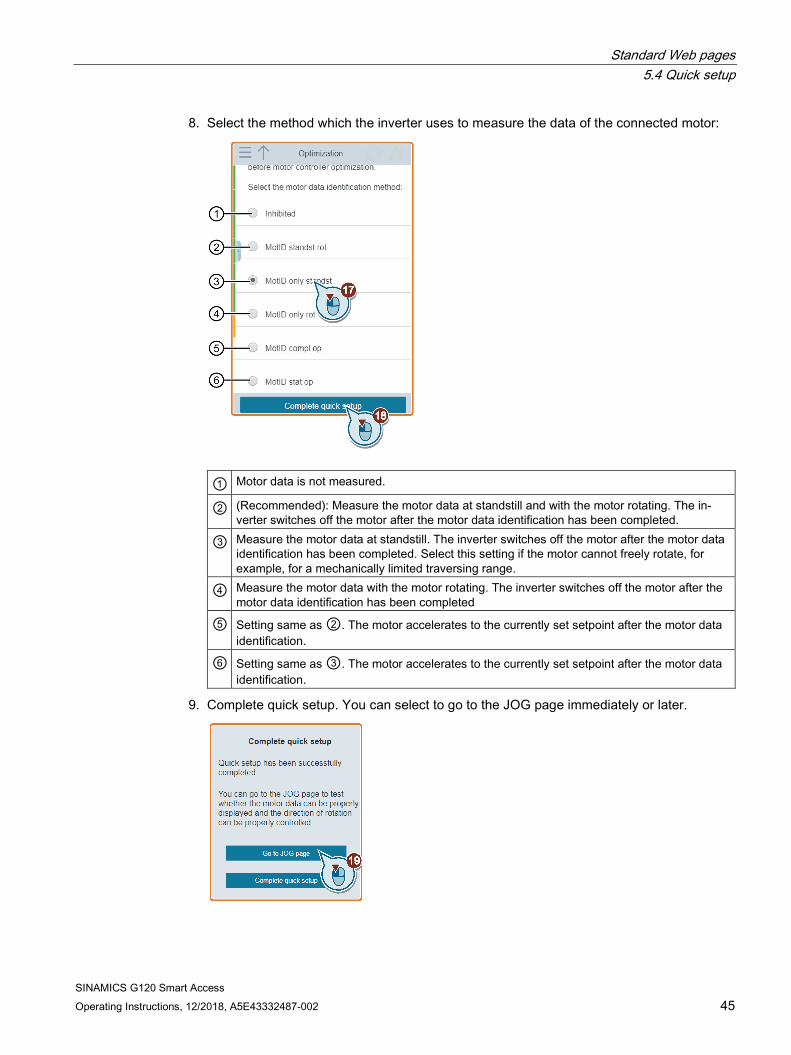
8. Select the method which the inverter uses to measure the data of the connected motor:
① Motor data is not measured.
② (Recommended): Measure the motor data at standstill and with the motor rotating. The in-verter switches off the motor after the motor data identification has been completed.
③ Measure the motor data at standstill. The inverter switches off the motor after the motor data identification has been completed. Select this setting if the motor cannot freely rotate, for example, for a mechanically limited traversing range.
④ Measure the motor data with the motor rotating. The inverter switches off the motor after the motor data identification has been completed
⑤ Setting same as ②. The motor accelerates to the currently set setpoint after the motor data identification.
⑥ Setting same as ③. The motor accelerates to the currently set setpoint after the motor data identification.
9. Complete quick setup. You can select to go to the JOG page immediately or later.
Standard Web pages 5.5 Parameters
SINAMICS G120 Smart Access 46 Operating Instructions, 12/2018, A5E43332487-002
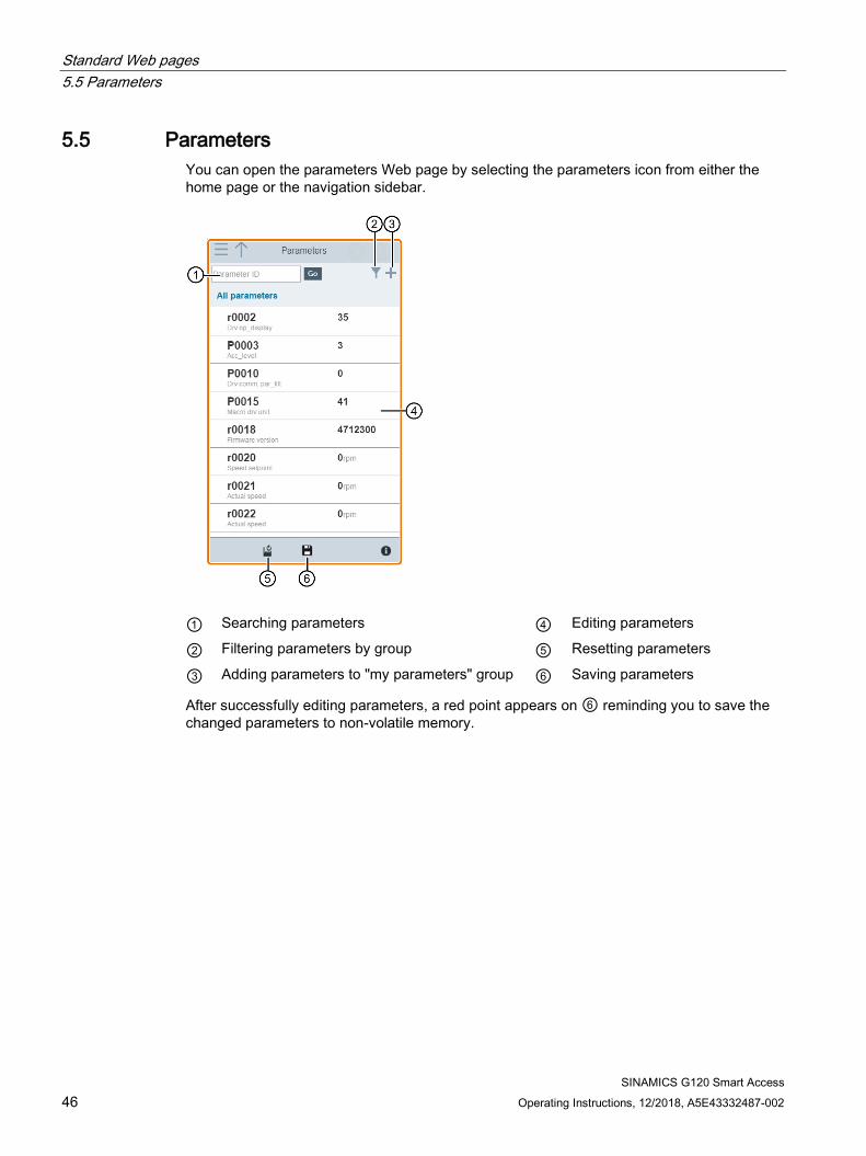
5.5 Parameters You can open the parameters Web page by selecting the parameters icon from either the home page or the navigation sidebar.
① Searching parameters ④ Editing parameters
② Filtering parameters by group ⑤ Resetting parameters
③ Adding parameters to "my parameters" group ⑥ Saving parameters
After successfully editing parameters, a red point appears on ⑥ reminding you to save the changed parameters to non-volatile memory.

Standard Web pages 5.5 Parameters
SINAMICS G120 Smart Access Operating Instructions, 12/2018, A5E43332487-002 47
Editing parameters The figure below shows different methods for editing parameters. Note that when editing a BICO parameter (example: P0771[0]), you can use the on-screen numeric keypad to quickly navigate to the parameter values that start with the number(s) you enter.
Standard Web pages 5.5 Parameters
SINAMICS G120 Smart Access 48 Operating Instructions, 12/2018, A5E43332487-002
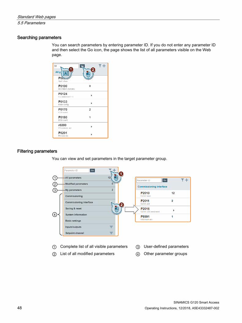
Searching parameters You can search parameters by entering parameter ID. If you do not enter any parameter ID and then select the Go icon, the page shows the list of all parameters visible on the Web page.
Filtering parameters You can view and set parameters in the target parameter group.
① Complete list of all visible parameters ③ User-defined parameters
② List of all modified parameters ④ Other parameter groups
Standard Web pages 5.5 Parameters
SINAMICS G120 Smart Access Operating Instructions, 12/2018, A5E43332487-002 49
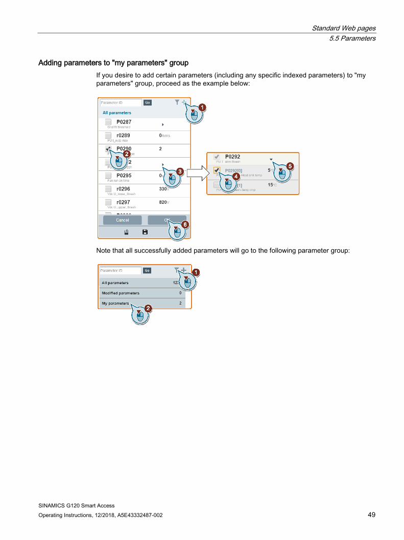
Adding parameters to "my parameters" group If you desire to add certain parameters (including any specific indexed parameters) to "my parameters" group, proceed as the example below:
Note that all successfully added parameters will go to the following parameter group:
Standard Web pages 5.5 Parameters
SINAMICS G120 Smart Access 50 Operating Instructions, 12/2018, A5E43332487-002
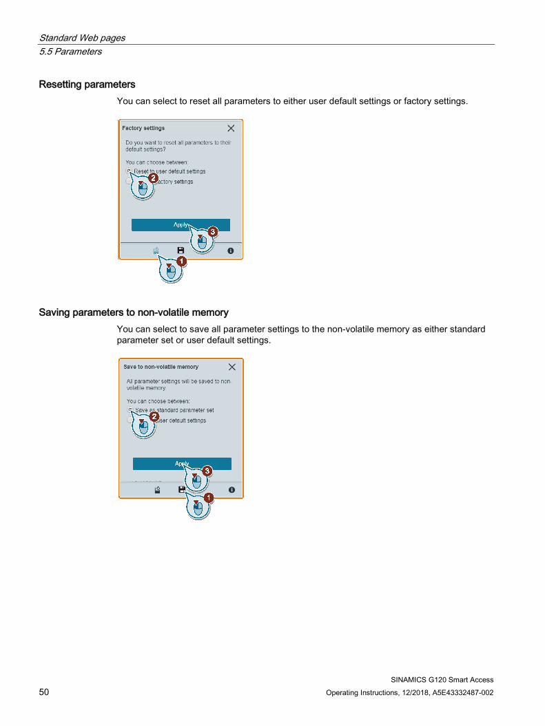
Resetting parameters You can select to reset all parameters to either user default settings or factory settings.
Saving parameters to non-volatile memory You can select to save all parameter settings to the non-volatile memory as either standard parameter set or user default settings.
Standard Web pages 5.6 JOG
SINAMICS G120 Smart Access Operating Instructions, 12/2018, A5E43332487-002 51
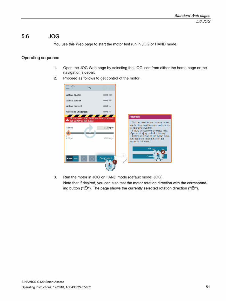
5.6 JOG You use this Web page to start the motor test run in JOG or HAND mode.
Operating sequence 1. Open the JOG Web page by selecting the JOG icon from either the home page or the
navigation sidebar. 2. Proceed as follows to get control of the motor.
3. Run the motor in JOG or HAND mode (default mode: JOG). Note that if desired, you can also test the motor rotation direction with the correspond-ing button ("①"). The page shows the currently selected rotation direction ("②").

Standard Web pages 5.6 JOG
SINAMICS G120 Smart Access 52 Operating Instructions, 12/2018, A5E43332487-002
• Press the desired button ("①") to run the motor in JOG mode:
• Proceed as follows to run the motor in HAND mode:
Standard Web pages 5.6 JOG
SINAMICS G120 Smart Access Operating Instructions, 12/2018, A5E43332487-002 53
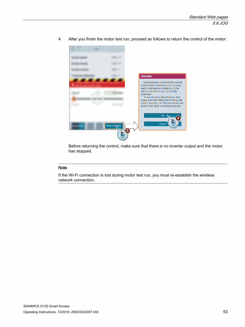
4. After you finish the motor test run, proceed as follows to return the control of the motor:
Before returning the control, make sure that there is no inverter output and the motor has stopped.
Note
If the Wi-Fi connection is lost during motor test run, you must re-establish the wireless network connection.

Standard Web pages 5.7 Monitoring
SINAMICS G120 Smart Access 54 Operating Instructions, 12/2018, A5E43332487-002
5.7 Monitoring You can open the inverter status monitoring Web page by selecting the monitoring icon from either the home page or the navigation sidebar.
5.8 Diagnostics You can open the diagnostics Web page by selecting the diagnostics icon from either the home page or the navigation sidebar. This page includes the following three subpages:
● Faults/alarms
● I/O status
● Status bits
Meaning of fault/alarm icons Fault and alarm icons are shown in the upper-right corner of the SINAMICS G120 Web page. See the following example for possible icon display:
Fault icons
① No active faults
② Active faults (in this example: one active fault)
Alarm icons
③ No active alarms
④ Active alarms (in this example: two active alarms)
Standard Web pages 5.8 Diagnostics
SINAMICS G120 Smart Access Operating Instructions, 12/2018, A5E43332487-002 55
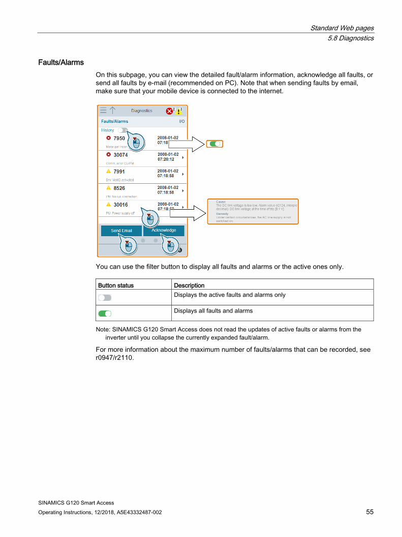
Faults/Alarms On this subpage, you can view the detailed fault/alarm information, acknowledge all faults, or send all faults by e-mail (recommended on PC). Note that when sending faults by email, make sure that your mobile device is connected to the internet.
You can use the filter button to display all faults and alarms or the active ones only. Button status Description
Displays the active faults and alarms only
Displays all faults and alarms
Note: SINAMICS G120 Smart Access does not read the updates of active faults or alarms from the inverter until you collapse the currently expanded fault/alarm.
For more information about the maximum number of faults/alarms that can be recorded, see r0947/r2110.

Standard Web pages 5.8 Diagnostics
SINAMICS G120 Smart Access 56 Operating Instructions, 12/2018, A5E43332487-002
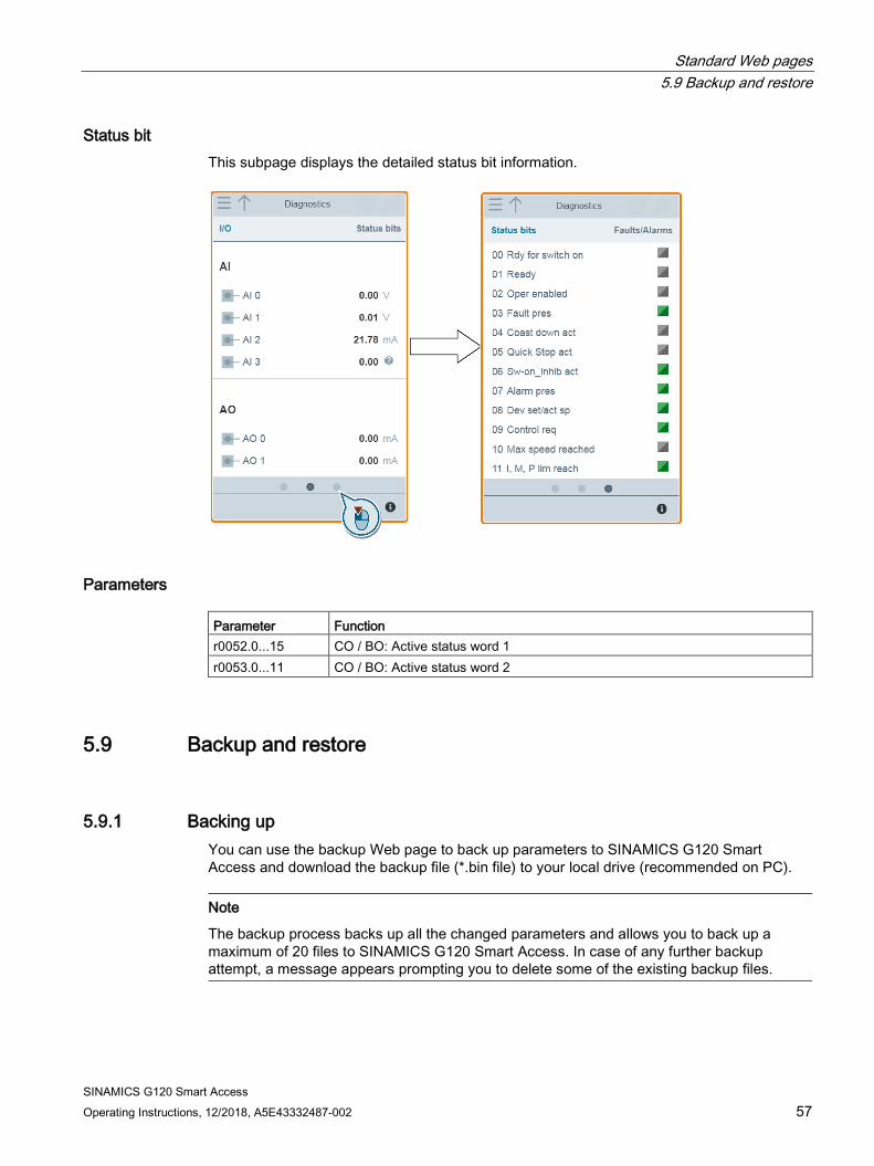
I/O status This subpage displays the detailed I/O status information.
Parameters Parameter Function r0722.0...n CO/BO: CU digital input status r0747.0...n CO/BO: CU digital output status r0752[0...n] Actual analog input value [V] or [mA] r0774[0...n] Actual analog output value [V] or [mA] P0756[0...n] Type of analog input P0776[0...n] Type of analog output
Standard Web pages 5.9 Backup and restore
SINAMICS G120 Smart Access Operating Instructions, 12/2018, A5E43332487-002 57
Status bit This subpage displays the detailed status bit information.
Parameters Parameter Function r0052.0...15 CO / BO: Active status word 1 r0053.0...11 CO / BO: Active status word 2
5.9 Backup and restore
5.9.1 Backing up You can use the backup Web page to back up parameters to SINAMICS G120 Smart Access and download the backup file (*.bin file) to your local drive (recommended on PC).
Note
The backup process backs up all the changed parameters and allows you to back up a maximum of 20 files to SINAMICS G120 Smart Access. In case of any further backup attempt, a message appears prompting you to delete some of the existing backup files.
Standard Web pages 5.9 Backup and restore
SINAMICS G120 Smart Access 58 Operating Instructions, 12/2018, A5E43332487-002
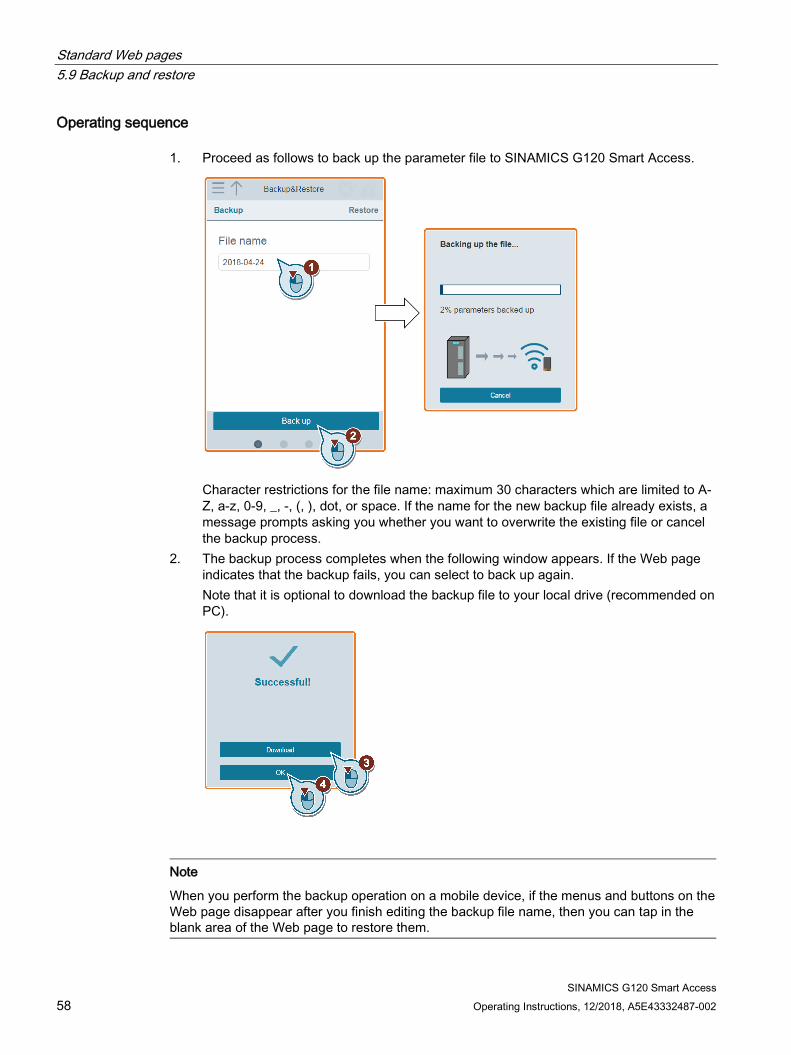
Operating sequence 1. Proceed as follows to back up the parameter file to SINAMICS G120 Smart Access.
Character restrictions for the file name: maximum 30 characters which are limited to A-Z, a-z, 0-9, _, -, (, ), dot, or space. If the name for the new backup file already exists, a message prompts asking you whether you want to overwrite the existing file or cancel the backup process.
2. The backup process completes when the following window appears. If the Web page indicates that the backup fails, you can select to back up again. Note that it is optional to download the backup file to your local drive (recommended on PC).
Note
When you perform the backup operation on a mobile device, if the menus and buttons on the Web page disappear after you finish editing the backup file name, then you can tap in the blank area of the Web page to restore them.
Standard Web pages 5.9 Backup and restore
SINAMICS G120 Smart Access Operating Instructions, 12/2018, A5E43332487-002 59
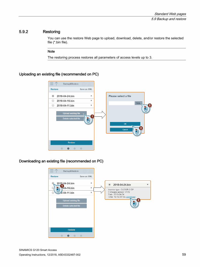
5.9.2 Restoring You can use the restore Web page to upload, download, delete, and/or restore the selected file (*.bin file).
Note
The restoring process restores all parameters of access levels up to 3.
Uploading an existing file (recommended on PC)
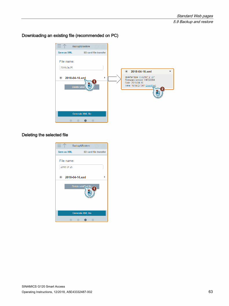
Downloading an existing file (recommended on PC)
Standard Web pages 5.9 Backup and restore
SINAMICS G120 Smart Access 60 Operating Instructions, 12/2018, A5E43332487-002
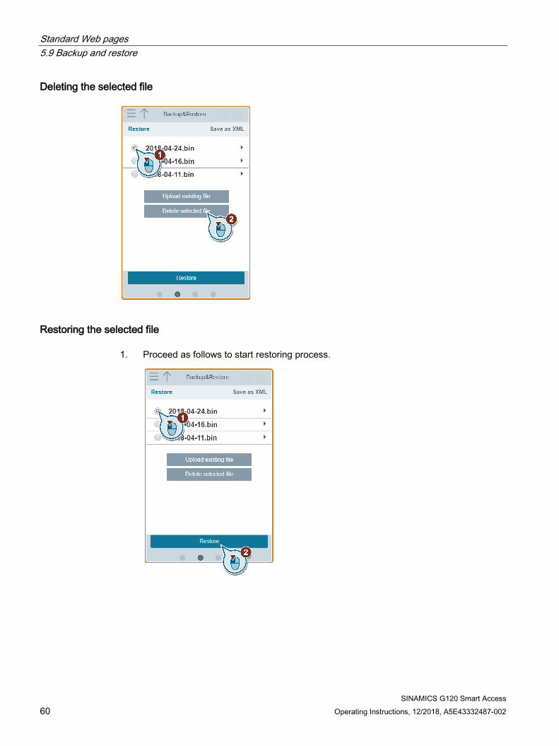
Deleting the selected file
Restoring the selected file 1. Proceed as follows to start restoring process.

Standard Web pages 5.9 Backup and restore
SINAMICS G120 Smart Access Operating Instructions, 12/2018, A5E43332487-002 61
2. The restoring process completes when the following window appears. If the Web page indicates that the restoring fails, you can select to restore again. If required, proceed as follows to save the parameter settings to the non-volatile memory:
Note
Make sure that the selected file for restoring is specific to the connected inverter.
5.9.3 Saving as XML You can use the saving Web page to save the parameters as XML and download the XML file to your local drive so that you can open and see the parameters.
Note
The saving process saves all parameters of access levels up to 3 and allows you to save a maximum of 20 files to SINAMICS G120 Smart Access. In case of any further saving attempt, a message appears prompting you to delete some of the existing XML files.
Standard Web pages 5.9 Backup and restore
SINAMICS G120 Smart Access 62 Operating Instructions, 12/2018, A5E43332487-002
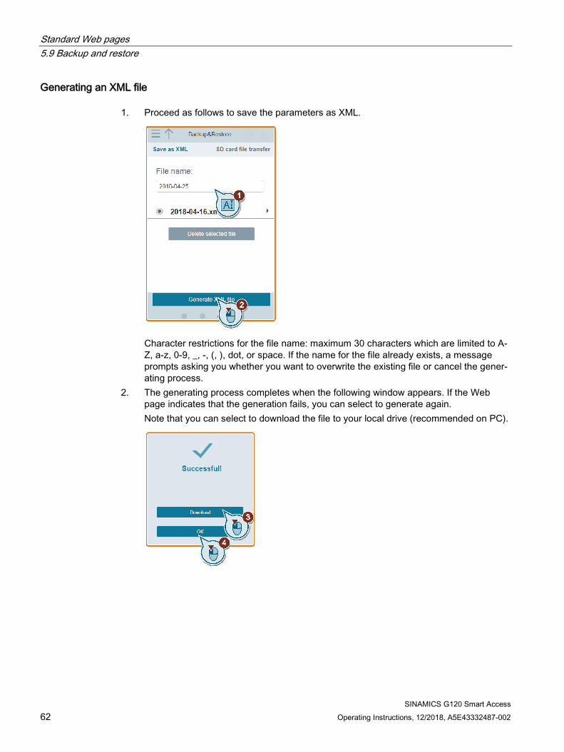
Generating an XML file 1. Proceed as follows to save the parameters as XML.
Character restrictions for the file name: maximum 30 characters which are limited to A-Z, a-z, 0-9, _, -, (, ), dot, or space. If the name for the file already exists, a message prompts asking you whether you want to overwrite the existing file or cancel the gener-ating process.
2. The generating process completes when the following window appears. If the Web page indicates that the generation fails, you can select to generate again. Note that you can select to download the file to your local drive (recommended on PC).
Standard Web pages 5.9 Backup and restore
SINAMICS G120 Smart Access Operating Instructions, 12/2018, A5E43332487-002 63
Downloading an existing file (recommended on PC)
Deleting the selected file
Standard Web pages 5.9 Backup and restore
SINAMICS G120 Smart Access 64 Operating Instructions, 12/2018, A5E43332487-002
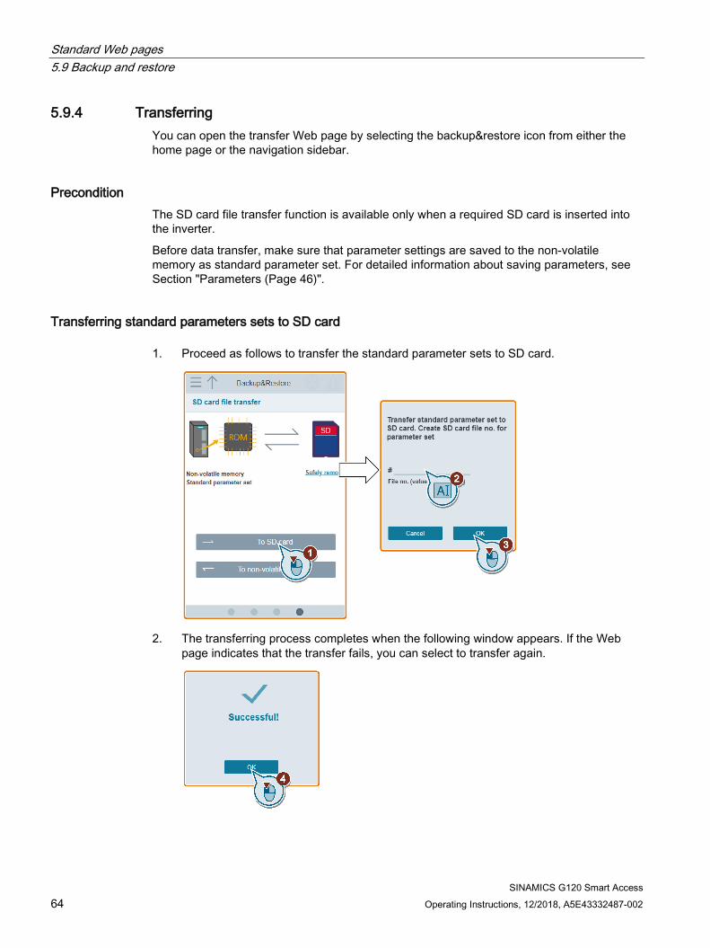
5.9.4 Transferring You can open the transfer Web page by selecting the backup&restore icon from either the home page or the navigation sidebar.
Precondition The SD card file transfer function is available only when a required SD card is inserted into the inverter.
Before data transfer, make sure that parameter settings are saved to the non-volatile memory as standard parameter set. For detailed information about saving parameters, see Section "Parameters (Page 46)".
Transferring standard parameters sets to SD card 1. Proceed as follows to transfer the standard parameter sets to SD card.
2. The transferring process completes when the following window appears. If the Web page indicates that the transfer fails, you can select to transfer again.
Standard Web pages 5.9 Backup and restore
SINAMICS G120 Smart Access Operating Instructions, 12/2018, A5E43332487-002 65
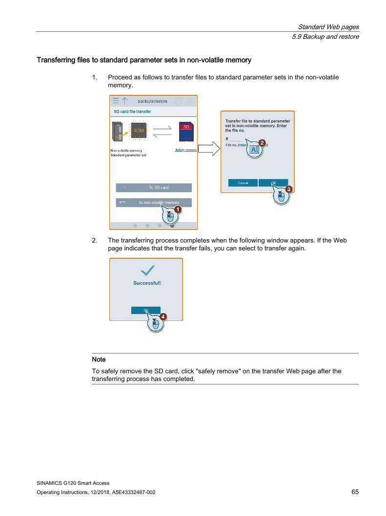
Transferring files to standard parameter sets in non-volatile memory 1. Proceed as follows to transfer files to standard parameter sets in the non-volatile
memory.
2. The transferring process completes when the following window appears. If the Web page indicates that the transfer fails, you can select to transfer again.
Note
To safely remove the SD card, click "safely remove" on the transfer Web page after the transferring process has completed.
Standard Web pages 5.10 Support
SINAMICS G120 Smart Access 66 Operating Instructions, 12/2018, A5E43332487-002
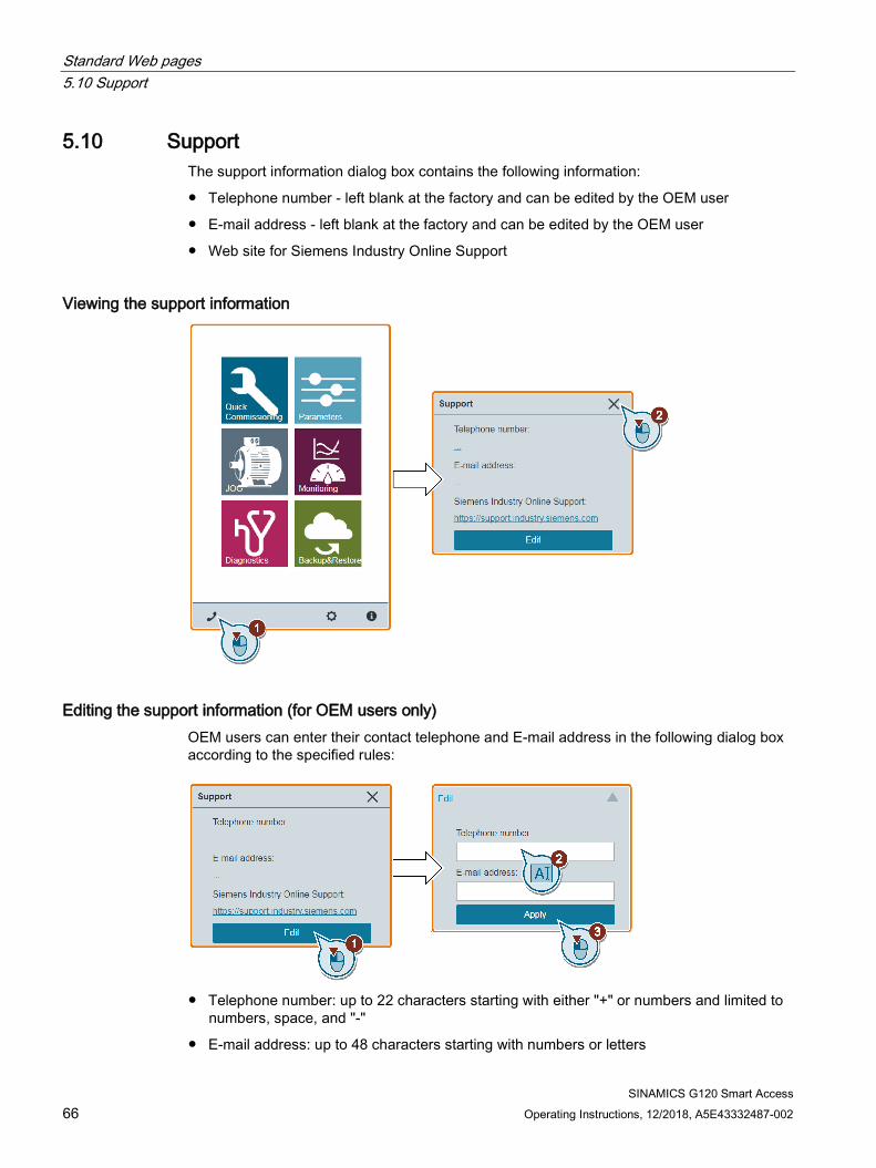
5.10 Support The support information dialog box contains the following information:
● Telephone number - left blank at the factory and can be edited by the OEM user
● E-mail address - left blank at the factory and can be edited by the OEM user
● Web site for Siemens Industry Online Support
Viewing the support information
Editing the support information (for OEM users only) OEM users can enter their contact telephone and E-mail address in the following dialog box according to the specified rules:
● Telephone number: up to 22 characters starting with either "+" or numbers and limited to
numbers, space, and "-"
● E-mail address: up to 48 characters starting with numbers or letters
SINAMICS G120 Smart Access Operating Instructions, 12/2018, A5E43332487-002 67
Upgrading 6Upgrading on the SINAMICS G120 Web page upgrades the firmware version of the SINAMICS G120 Smart Access.
Two upgrading methods are available:
● Conventional upgrading
● Basic upgrading (applicable when conventional upgrading fails)
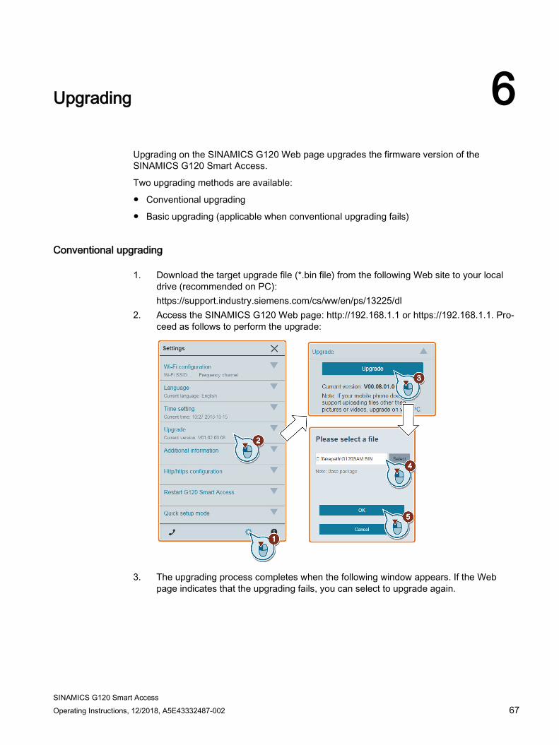
Conventional upgrading
1. Download the target upgrade file (*.bin file) from the following Web site to your localdrive (recommended on PC):https://support.industry.siemens.com/cs/ww/en/ps/13225/dl
2. Access the SINAMICS G120 Web page: http://192.168.1.1 or https://192.168.1.1. Pro-ceed as follows to perform the upgrade:
3. The upgrading process completes when the following window appears. If the Webpage indicates that the upgrading fails, you can select to upgrade again.

Upgrading
SINAMICS G120 Smart Access 68 Operating Instructions, 12/2018, A5E43332487-002
4. Restart the SINAMICS G120 Smart Access. Note that if you do not click "Restart G120 Smart Access now", the SINAMICS G120 Smart Access will restart automatically after the 10-second countdown time has elapsed.
5. Clear the browser cache. 6. Refresh your Web application.
Note Uploading self-signed certificates
If you want to replace the default certificates with self-signed ones, you can upload the certificates in the conventional upgrading page. You can use any tool available to create self-signed certificates as long as they adhere to these settings: • The two certificate file names must be servercert.der and serverkey.der respectively.
After uploading the two certificate files, you must install the SSL certificates.
Basic upgrading 1. Download the target upgrade file (*.bin file) from the following Web site to your local
drive (recommended on PC): https://support.industry.siemens.com/cs/ww/en/ps/13225/dl
2. Hold down the reset button when the module is in power-off state and then power on the module.
3. Open the following Web site specific for basic upgrading: http://192.168.1.1/factory/basicupgrade.html
Upgrading
SINAMICS G120 Smart Access Operating Instructions, 12/2018, A5E43332487-002 69
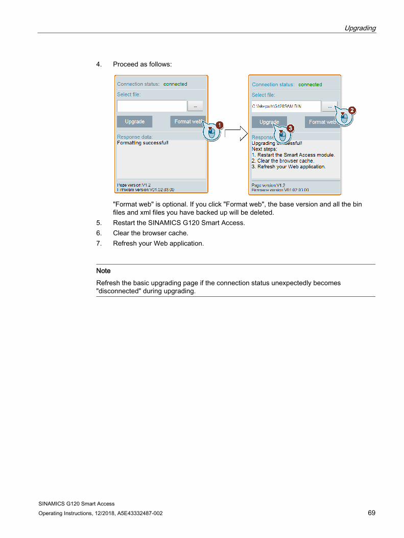
4. Proceed as follows:
"Format web" is optional. If you click "Format web", the base version and all the bin files and xml files you have backed up will be deleted.
5. Restart the SINAMICS G120 Smart Access. 6. Clear the browser cache. 7. Refresh your Web application.
Note
Refresh the basic upgrading page if the connection status unexpectedly becomes "disconnected" during upgrading.
SINAMICS G120 Smart Access 70 Operating Instructions, 12/2018, A5E43332487-002
Additional information 7 7.1 Product information
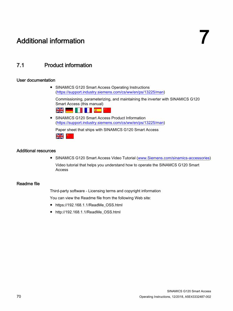
User documentation ● SINAMICS G120 Smart Access Operating Instructions
(https://support.industry.siemens.com/cs/ww/en/ps/13225/man)
Commissioning, parameterizing, and maintaining the inverter with SINAMICS G120 Smart Access (this manual)
● SINAMICS G120 Smart Access Product Information (https://support.industry.siemens.com/cs/ww/en/ps/13225/man)
Paper sheet that ships with SINAMICS G120 Smart Access
Additional resources ● SINAMICS G120 Smart Access Video Tutorial (www.Siemens.com/sinamics-accessories)
Video tutorial that helps you understand how to operate the SINAMCS G120 Smart Access
Readme file Third-party software - Licensing terms and copyright information
You can view the Readme file from the following Web site:
● https://192.168.1.1/ReadMe_OSS.html
● http://192.168.1.1/ReadMe_OSS.html
Additional information 7.2 Product support
SINAMICS G120 Smart Access Operating Instructions, 12/2018, A5E43332487-002 71
7.2 Product support For more information about the product, please visit:
Product support (http://www.siemens.com/automation/service&support)
This address provides the following:
● Actual product information (product memorandums), FAQs (frequently asked questions), downloads.
● The Newsletter contains the latest information on the products you use.
● The Knowledge Manager (Intelligent Search) helps you find the documents you need.
● Users and specialists from around the world share their experience and knowledge in the Forum.
● You can find your local representative for Automation & Drives via our contact database under "Contact & Partner".
● Information about local service, repair, spare parts and much more can be found under "Services".
Additional information 7.3 Technical specifications
SINAMICS G120 Smart Access 72 Operating Instructions, 12/2018, A5E43332487-002
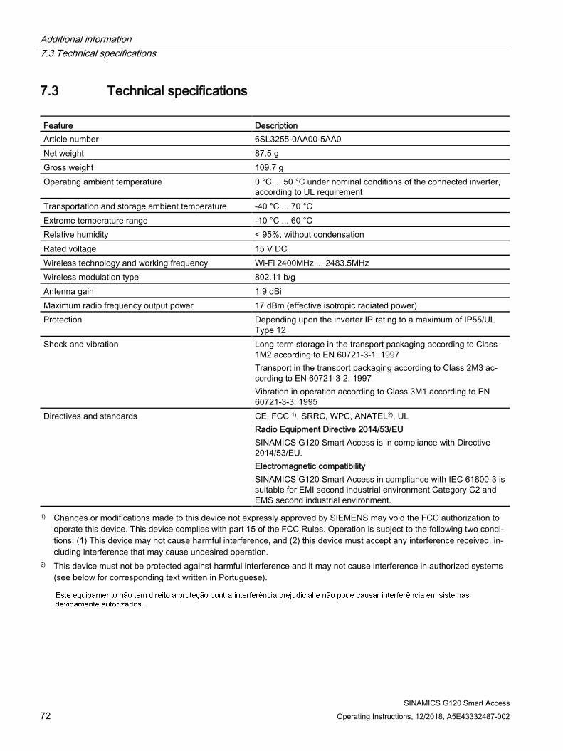
7.3 Technical specifications
Feature Description Article number 6SL3255-0AA00-5AA0 Net weight 87.5 g Gross weight 109.7 g Operating ambient temperature 0 °C ... 50 °C under nominal conditions of the connected inverter,
according to UL requirement Transportation and storage ambient temperature -40 °C ... 70 °CExtreme temperature range -10 °C ... 60 °CRelative humidity < 95%, without condensation Rated voltage 15 V DC Wireless technology and working frequency Wi-Fi 2400MHz ... 2483.5MHz Wireless modulation type 802.11 b/g Antenna gain 1.9 dBi Maximum radio frequency output power 17 dBm (effective isotropic radiated power) Protection Depending upon the inverter IP rating to a maximum of IP55/UL
Type 12 Shock and vibration Long-term storage in the transport packaging according to Class
1M2 according to EN 60721-3-1: 1997 Transport in the transport packaging according to Class 2M3 ac-cording to EN 60721-3-2: 1997 Vibration in operation according to Class 3M1 according to EN 60721-3-3: 1995
Directives and standards CE, FCC 1), SRRC, WPC, ANATEL2), UL Radio Equipment Directive 2014/53/EU SINAMICS G120 Smart Access is in compliance with Directive 2014/53/EU. Electromagnetic compatibility SINAMICS G120 Smart Access in compliance with IEC 61800-3 is suitable for EMI second industrial environment Category C2 and EMS second industrial environment.
1) Changes or modifications made to this device not expressly approved by SIEMENS may void the FCC authorization tooperate this device. This device complies with part 15 of the FCC Rules. Operation is subject to the following two condi-tions: (1) This device may not cause harmful interference, and (2) this device must accept any interference received, in-cluding interference that may cause undesired operation.
2) This device must not be protected against harmful interference and it may not cause interference in authorized systems(see below for corresponding text written in Portuguese).