single axis devices -...
TRANSCRIPT
Compax3 Electromechanical Automation
We reserve the right to make technical changes. 13.12.10 13:24 192-120102 N16 December 2010 The data correspond to the current status at the time of printing.
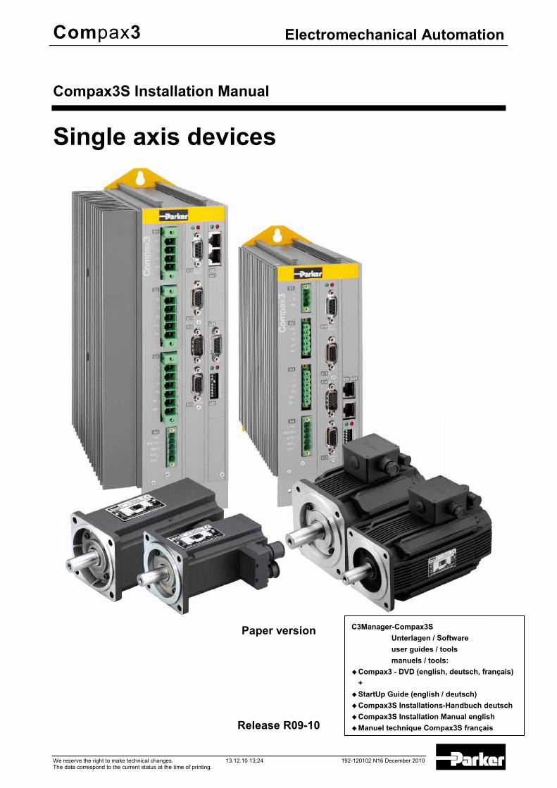
Compax3S Installation Manual
Single axis devices
Paper version
Release R09-10
C3Manager-Compax3S
Unterlagen / Software user guides / tools manuels / tools:
Compax3 - DVD (english, deutsch, français) +
StartUp Guide (english / deutsch) Compax3S Installations-Handbuch deutsch Compax3S Installation Manual english Manuel technique Compax3S français
Notes on the Documents Supplied Single axis devices
2 192-120102 N16 December 2010
____________________________
Windows NT®, Windows 2000™, Windows XP™, Windows Vista are trademarks of Microsoft Corporation.
nonwarranty clause We checked the contents of this publication for compliance with the associated hard and software. We can, however, not exclude discrepancies and do therefore not accept any liability for the exact compliance. The information in this publication is regularly checked, necessary corrections will be part of the subsequent publications.
Worldwide sales http://divapps.parker.com/divapps/eme/EME/Contact_sites/Sales%20Channel_Parker-EME.pdf
Production site: Parker Hannifin GmbH Electromechanical Automation Europe [EME] Robert-Bosch-Strasse 22 77656 Offenburg (Germany) Tel.: + 49 (0781) 509-0 Fax: + 49 (0781) 509-98176 Internet: www.parker-eme.com http://www.parker-eme.com E-mail: [email protected] mailto:[email protected] Parker Hannifin GmbH - registered office: Bielefeld HRB 35489 Geschäftsführung: Dr. Gerd Scheffel, Günter Schrank, Christian Stein, Kees Veraart - Aufsichtsratsvorsitzender: Hansgeorg Greuner
Headquarters:
Parker Hannifin PLC • Electromechanical Automation • Arena Business Centre Holy Rood Close • Poole, Dorset BH17 7FJ UK Tel.: +44 (0)1202 606300 • Fax: +44 (0)1202 606301 E-mail: [email protected] mailto:[email protected] • Internet: www.parker-eme.com http://www.parker-eme.com
Parker Hannifin S.p.A • SSD SBC • Electromechanical Automation • Via Gounod, 1 I-20092 Cinisello Balsamo (MI), Italy Tel.: +39 (0)2 66012459 • Fax: +39 (0)2 66012808 E-mail: [email protected] mailto:[email protected] • Internet: www.parker-eme.com http://www.parker-eme.com
Parker Hannifin Corporation • Electromechanical Automation 5500 Business Park Drive • Rohnert Park, CA 94928 Phone #: (800) 358-9068 • FAX #: (707) 584-3715 E-mail: [email protected] mailto:[email protected] • Internet: www.compumotor.com http://www.compumotor.com
Our product on the Internet: http://www.parker-eme.com/c3
England:
Italy:
USA:

Parker EME Notes on the Documents Supplied
192-120102 N16 December 2010 3
The present manual contains the installation instructions for the associated Compax3 device series (see on page 7).
This installation manual does contain only the basic information; for more detailed information please refer to the Help-files of the individual Compax3
device types.
Compax3 - DVD The enclosed self-starting* DVD contains the “C3 ServoManager” software tool for configuring, optimizing etc. Compax3. Please use always the latest C3 ServoManager version, Furthermore, the "Parker Integrated Engineering Tool", a software tool for the project management of several Parker Motion Control products, can be found on the C3 DVD. Several axes are managed in a common project. The Compax3 ServoManager is integrated per "Plug & Play" for each Compax3 axis. The configuration, optimization,.. take place in the same way as in an independently working C3 ServoManager.
The "C3 ServoManager" software tool is also functioning independently from the Parker Integrated Engineering Tool!
After the installation of the ServoManager you can copy the desired Online help system with the "C3 ServoManager Help Installer" (you can select the C3 device type as well as the desired language) to your PC. The help system can be called up directly from the ServoManager. You will find the complete description of the selected device type in these online help files. Please note that the help files are associated with defined device and software versions. The catalogs supplied provide an overview of and information on the Compax3 device series. For reading PDF files you need the "Adobe Acrobat Reader", a software tool which is available free of charge. It is distributed and generally accepted throughout the world. You can also download it directly from the Adobe website. * If your PC has not been set up accordingly, start the "start.htm" file on the CD.
1. Notes on the Documents Supplied
Compax3 - Installation manual
C3 ServoManager
Parker Integrated Engineering Tool
Online help system
Catalogs
Adobe Acrobat Reader®
Notes on the Documents Supplied Single axis devices
4 192-120102 N16 December 2010
1.1 C3 ServoManager
The Compax3 ServoManager can be installed directly from the Compax3 DVD. Click on the corresponding hyperlink resp. start the installation program "C3Mgr_Setup_V.....exe" and follow the instructions.
PC requirements
Recommendation: Operating system: MS Windows XP SP2 / MS Windows 2000 as from SP4 / (MS Vista) Browser: MS Internet Explorer 6.x Processor: Intel Pentium 4 / Intel Core 2 Duo / AMD Athlon class as from
>=2GHz RAM memory: >= 1024MB Hard disk: >= 20GB available memory Drive: DVD drive Monitor: Resolution 1024x768 or higher
Graphics card: on onboard graphics (for performance reasons) Interface: USB Minimum requirements: Operating system: MS Windows XP SP2 / MS Windows 2000 as from SP4 Browser: MS Internet Explorer 6.x Processor: >=1.5GHz RAM memory: 512MB Hard disk: 10GB available memory Drive: DVD drive Monitor: Resolution 1024x768 or higher Graphics card: on onboard graphics (for performance reasons) Interface: USB Note: For the installation of the software you need administrator authorization on the
target computer. Several applications running in parallel, reduce the performance and operability. Especially customer applications, exchanging standard system components
(drivers) in order to improve their own performance, may have a strong influence on the communication performance or even render normal use impossible.
Operation under virtual machines such as Vware Workstation 6/ MS Virtual PC is not possible.
Onboard graphics card solutions reduce the system performance by up to 20% and cannot be recommended.
Operation with notebooks in current-saving mode may lead, in individual cases, to communication problems.
Your PC is connected with Compax3 via a RS232 cable (SSK1). Cable SSK1 (COM 1/2-interface on the PC to X10 on the Compax3 or via adapter SSK32/20 on programming interface of Compax3H). Start the Compax3 ServoManager and make the setting for the selected interface in the "Options Communication settings RS232/RS485..." menu.
In the menu tree under device selection you can read the device type of the connected device (Online Device Identification) or select a device type (Device Selection Wizard).
Then you can double click on "Configuration" to start the configuration wizard. The wizard will lead you through all input windows of the configuration.
Installation of the C3 ServoManager
Connection between PC and
Compax3
Device Selection
Configuration

Parker EME Notes on the Documents Supplied
192-120102 N16 December 2010 5
Inhalt 1. Notes on the Documents Supplied ........................................................ 3
1.1 C3 ServoManager ..................................................................................... 4
2. Introduction ............................................................................................. 7
2.1 Device assignment .................................................................................. 7
2.2 Scope of delivery ..................................................................................... 7
2.3 Type specification plate .......................................................................... 8
2.4 Packaging, transport, storage ................................................................ 9
2.5 Safety instructions ................................................................................. 11 2.5.1. General hazards ............................................................................................... 11 2.5.2. Safety-conscious working .............................................................................. 11 2.5.3. Special safety instructions ............................................................................. 12
2.6 Warranty conditions .............................................................................. 13
2.7 Conditions of utilization for CE-conform operation ............................ 14 2.7.1. Conditions of utilization mains filter ............................................................. 14 2.7.2. Conditions of utilization for cables / motor filter.......................................... 15 2.7.3. Additional conditions of utilization ................................................................ 15
2.8 EC declaration of conformity ................................................................ 17
3. Compax3 device description ................................................................ 18
3.1 State of delivery ..................................................................................... 18
3.2 Meaning of the status LEDs - Compax3 axis controller ..................... 18
3.3 Connections of Compax3S ................................................................... 19 3.3.1. Compax3S connectors .................................................................................... 19 3.3.2. Connector and pin assignment C3S .............................................................. 20 3.3.3. Control voltage 24VDC / enable connector X4 C3S ..................................... 22 3.3.4. Motor / Motor brake (C3S connector X3) ....................................................... 23 3.3.5. Compax3Sxxx V2 ............................................................................................. 24 3.3.6. Compax3Sxxx V4 ............................................................................................. 26
3.4 Signal interfaces .................................................................................... 28 3.4.1. RS232/RS485 interface (plug X10) ................................................................. 28 3.4.2. Resolver / feedback (plug X13) ...................................................................... 29 3.4.3. Analogue / encoder (plug X11) ....................................................................... 30 3.4.4. Digital inputs/outputs (plug X12) ................................................................... 31
3.5 Installation and dimensions Compax3 ................................................. 32 3.5.1. Mounting and dimensions Compax3S0xxV2 ................................................ 32 3.5.2. Mounting and dimensions Compax3S100V2 and S0xxV4 ........................... 33

Notes on the Documents Supplied Single axis devices
6 192-120102 N16 December 2010
3.5.3. Mounting and dimensions Compax3S150V2 and S150V4 ........................... 34 3.5.4. Mounting and dimensions Compax3S300V4 ................................................ 35
4. Technical Characteristics ..................................................................... 36
5. Index ....................................................................................................... 42
Parker EME Introduction
192-120102 N16 December 2010 7
In diesem Kapitel finden Sie Device assignment ............................................................................................................ 7 Scope of delivery ............................................................................................................... 7 Type specification plate ..................................................................................................... 8 Packaging, transport, storage ............................................................................................ 9 Safety instructions ........................................................................................................... 11 Warranty conditions ......................................................................................................... 13 Conditions of utilization for CE-conform operation ............................................................ 14 EC declaration of conformity ............................................................................................ 17
2.1 Device assignment
This manual is valid for the following devices: Compax3S025V2 + supplement Compax3S063V2 + supplement Compax3S100V2 + supplement Compax3S150V2 + supplement Compax3S015V4 + supplement Compax3S038V4 + supplement Compax3S075V4 + supplement Compax3S150V4 + supplement Compax3S300V4 + supplement
2.2 Scope of delivery
The following items are furnished with the device: Manuals* Installation manual (German, English, French) Compax3 DVD Startup Guide (German / English)
*Comprehensiveness of documentation depends on device type Device accessories
Device accessories for Compax3S Cable clamps in different sizes for large area shielding of the motor cable, the
screw for the cable clamp as well as the mating plug connectors for the Compax3S plug connectors X1, X2, X3, and
X4 a toroidal core ferrite for one cable of the motor holding brake Lacing cord
2. Introduction
Introduction Single axis devices
8 192-120102 N16 December 2010
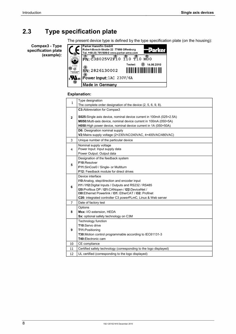
2.3 Type specification plate The present device type is defined by the type specification plate (on the housing):
Explanation:
1 Type designation The complete order designation of the device (2, 5, 6, 9, 8).
2
C3:Abbreviation for Compax3 S025:Single axis device, nominal device current in 100mA (025=2.5A) M050:Multi-axis device, nominal device current in 100mA (050=5A) H050:High power device, nominal device current in 1A (050=50A)
D6: Designation nominal supply V2:Mains supply voltage (2=230VAC/240VAC, 4=400VAC/480VAC)
3 Unique number of the particular device
4 Nominal supply voltage Power Input: Input supply data Power Output: Output data
5
Designation of the feedback system F10:Resolver F11:SinCos© / Single- or Multiturn F12: Feedback module for direct drives
6
Device interface I10:Analog, step/direction and encoder input I11 / I12:Digital Inputs / Outputs and RS232 / RS485 I20:Profibus DP / I21:CANopen / I22:DeviceNet / I30:Ethernet Powerlink / I31: EtherCAT / I32: Profinet C20: integrated controller C3 powerPLmC, Linux & Web server
7 Date of factory test
8 Options Mxx: I/O extension, HEDA Sx: optional safety technology on C3M
9
Technology function T10:Servo drive T11:Positioning T30:Motion control programmable according to IEC61131-3 T40:Electronic cam
10 CE compliance 11 Certified safety technology (corresponding to the logo displayed)
12 UL certified (corresponding to the logo displayed)
Compax3 - Type specification plate
(example):
Parker EME Introduction
192-120102 N16 December 2010 9
2.4 Packaging, transport, storage
Packaging material and transport
Caution!
The packaging material is inflammable, if it is disposed of improperly by burning, lethal fumes may develop. The packaging material must be kept and reused in the case of a return shipment. Improper or faulty packaging may lead to transport damages. Make sure to transport the drive always in a safe manner and with the aid of suitable lifting equipment (Weight (see on page 36)). Do never use the electric connections for lifting. Before the transport, a clean, level surface should be prepared to place the device on. The electric connections may not be damaged when placing the device.
First device checkup Check the device for signs of transport damages. Please verify, if the indications on the Type identification plate (see on page 8)
correspond to your requirements. Check if the consignment is complete.
Disposal
This product contains materials that fall under the special disposal regulation from 1996, which corresponds to the EC directory 91/689/EEC for dangerous disposal material. We recommend to dispose of the respective materials in accordance with the respectively valid environmental laws. The following table states the materials suitable for recycling and the materials which have to be disposed of separately. Material Option suitable for
recycling Disposal
Metal yes no
Plastic materials yes no
Circuit boards no yes Please dispose of the circuit boards according to one of the following methods: Burning at high temperatures (at least 1200°C) in an incineration plant licensed in
accordance with part A or B of the environmental protection act. Disposal via a technical waste dump which is allowed to take on electrolytic
aluminum condensers. Do under no circumstances dump the circuit boards at a place near a normal waste dump.
Storage
If you do not wish to mount and install the device immediately, make sure to store it in a dry and clean environment (see on page 40). Make sure that the device is not stored near strong heat sources and that no metal chippings can get into the device.

Introduction Single axis devices
10 192-120102 N16 December 2010
Forming the capacitors
Forming the capacitors only required with 400VAC axis controllers and PSUP mains module
If the device was stored longer than one year, the intermediate capacitors must be re-formed!
Forming sequence: Remove all electric connections Supply the device with 230VAC single phase for 30 minutes via the L1 and L2 terminals on the device or multi axis devices via L1 and L2 on the PSUP mains module
Please note in the event of storage >1
year:
Parker EME Introduction
192-120102 N16 December 2010 11
2.5 Safety instructions In diesem Kapitel finden Sie General hazards .............................................................................................................. 11 Safety-conscious working ................................................................................................ 11 Special safety instructions ............................................................................................... 12
2.5.1. General hazards General Hazards on Non-Compliance with the Safety Instructions The device described in this manual is designed in accordance with the latest technology and is safe in operation. Nevertheless, the device can entail certain hazards if used improperly or for purposes other than those explicitly intended. Electronic, moving and rotating components can constitute a hazard for body and life of the user, and cause material damage
Usage in accordance with intended purpose The device is designed for operation in electric power drive systems (VDE0160). Motion sequences can be automated with this device. Several motion sequences can be combined by interconnecting several of these devices. Mutual interlocking functions must be incorporated for this purpose.
2.5.2. Safety-conscious working This device may be operated only by qualified personnel. Qualified personnel in the sense of these operating instructions consists of: Persons who, by virtue to their training, experience and instruction, and their
knowledge of pertinent norms, specifications, accident prevention regulations and operational relationships, have been authorized by the officer responsible for the safety of the system to perform the required task and in the process are capable of recognizing potential hazards and avoiding them (definition of technical personnel according to VDE105 or IEC364),
Persons who have a knowledge of first-aid techniques and the local emergency rescue services.
persons who have read and will observe the safety instructions. Those who have read and observe the manual or help (or the sections pertinent
to the work to be carried out). This applies to all work relating to setting up, commissioning, configuring, programming, modifying the conditions of utilization and operating modes, and to maintenance work. This manual and the help information must be available close to the device during the performance of all tasks.

Introduction Single axis devices
12 192-120102 N16 December 2010
2.5.3. Special safety instructions Check the correct association of the device and its documentation. Never detach electrical connections while voltage is applied to them. Safety devices must be provided to prevent human contact with moving or
rotating parts. Make sure that the device is operated only when it is in perfect condition. Implement and activate the stipulated safety functions and devices. Operate the device only with the housing closed. Make sure that all devices are sufficiently fixed. Check that all live terminals are secured against contact. Perilous voltage levels
of up to 850V occur. Do not bypass power direct current
Caution!
Due to movable machine parts and high voltages, the device can pose a lethal danger. Danger of electric shock in the case of non-respect of the following instructions. The device corresponds to DIN EN 61800-3, i.e. it is subject to limited sale. The device can emit disturbances in certain local environments. In this case, the user is liable to take suitable measures. The device must be permanently grounded due to high earth leakage currents. The drive motor must be grounded with a suitable protective lead. The devices are equipped with high voltage DC condensers. Before removing the
protective cover, the discharging time must be awaited. After switching off the supply voltage, it may take up to 10 minutes to discharge the capacitors. Danger of electric shock in case of non respect.
Before you can work on the device, the supply voltage must be switched off at the L1, L2 and L3 clamps. Wait at least 10 minutes so that the power direct current may sink to a secure value (<50V). Check with the aid of a voltmeter, if the voltage at the DC+ and DC- clamps has fallen to a value below 50V. Danger of electric shock in case of non respect.
Do never perform resistance tests with elevated voltages (over 690V) on the wiring without separating the circuit to be tested from the drive.
Please exchange devices only in currentless state and, in an axis system, only in a defined original state.
In the event of a axis controller device exchange it is absolutely necessary to transfer the configuration determining the correct operation of the drive to the device, before the device is put into operation. Depending on the operation mode, a machine zero run will be necessary.
The device contains electrostatically sensitive components. Please heed the electrostatic protection measures while working at/with the device as well as during installation and maintenance.
Operation of the PSUP30 only with mains filter.
Attention - hot surface!
The heat dissipator can reach very high temperatures (>70°C)
Protective seals
Caution!
The user is responsible for protective covers and/or additional safety measures in order to prevent damages to persons and electric accidents.
Parker EME Introduction
192-120102 N16 December 2010 13
Forming the capacitors
Forming the capacitors only required with 400VAC axis controllers and PSUP mains module
If the device was stored longer than one year, the intermediate capacitors must be re-formed!
Forming sequence: Remove all electric connections Supply the device with 230VAC single phase for 30 minutes via the L1 and L2 terminals on the device or multi axis devices via L1 and L2 on the PSUP mains module
2.6 Warranty conditions
The device must not be opened. Do not make any modifications to the device, except for those described in the
manual. Make connections to the inputs, outputs and interfaces only in the manner
described in the manual. Fix the devices according to the mounting instructions (see on page 32).
We cannot provide any guarantee for other mounting methods. Note on exchange of options Device options must be exchanged in the factory to ensure hardware and software compatibility.
When installing the device, make sure the heat dissipators of the device receive sufficient air and respect the recommended mounting distances of the devices with integrated ventilator fans in order to ensure free circulation of the cooling air.
Make sure that the mounting plate is not exposed to external temperature influences.
Please note in the event of storage >1
year:

Introduction Single axis devices
14 192-120102 N16 December 2010
2.7 Conditions of utilization for CE-conform operation In diesem Kapitel finden Sie Conditions of utilization mains filter .................................................................................. 14 Conditions of utilization for cables / motor filter ................................................................ 15 Additional conditions of utilization .................................................................................... 15
- Industry and trade - The EC guidelines for electromagnetic compatibility 2004/108/EC and for electrical operating devices for utilization within certain voltage limits 2006/95/EC are fulfilled when the following boundary conditions are observed:
Operation of the devices only in the condition in which they were delivered, i.e. with all housing panels.
In order to ensure contact protection, all mating plugs must be present on the device connections even if they are not wired. Please respect the specifications of the manual, especially the technical characteristics (mains connection, circuit breakers, output data, ambient conditions,...).
2.7.1. Conditions of utilization mains filter A mains filter is required in the mains input line if the motor cable exceeds a certain length. Filtering can be provided centrally at the system mains input or separately for each device.
Use of the devices in a commercial and residential area (limit value class in accordance with EN 61800-3) The following mains filters are available for independent utilization: Device: Compax3S
Limit value class
Motor cable length Mains filter Order No.:
S0xxV2
C2 < 10 m without C2 > 10 m, < 100 m NFI01/01
S1xxV2, S0xxV4, S150V4
C2 < 10 m without C2 > 10 m, < 100 m NFI01/02
S300V4
C3 < 10 m without C2, C3 > 10 m, < 100 m NFI01/03
Connection length: Connection between mains filter and device: unshielded: < 0.5 m shielded < 5 (fully shielded on ground - e.g. ground of control cabinet)
Mains filter:

Parker EME Introduction
192-120102 N16 December 2010 15
2.7.2. Conditions of utilization for cables / motor filter
Operation of the devices only with motor and feedback cables whose plugs contain a special full surface area screening.
< 100 m (the cable should not be rolled up!) A motor output filter is required for motor cables >20 m: MDR01/04 (max. 6.3 A rated motor current) MDR01/01 (max. 16 A rated motor current) MDR01/02 (max. 30 A rated motor current)
Shielding connection of the motor cable The cable must be fully-screened and connected to the Compax3 housing. Use the cable clamps/shield connecting terminals furnished with the device. The shield of the cable must also be connected with the motor housing. The fixing (via plug or screw in the terminal box) depends on the motor type.
< 100 m
Corresponding to the specifications of the terminal clamp with a temperature range of up to 60°C.
Signal lines and power lines should be installed as far apart as possible. Signal lines should never pass close to excessive sources of interference
(motors, transformers, contactors etc.). Do not place mains filter output cable parallel to the load cable.
2.7.3. Additional conditions of utilization Operation with standard motors.
Use only with aligned controller (to avoid control loop oscillation).
Connect the filter housing and the device to the cabinet frame, making sure that the contact area is adequate and that the connection has low resistance and low inductance. Never mount the filter housing and the device on paint-coated surfaces!
For CE and UL conform operation of the Compax3S300V4, a mains filter is compulsory: 400 VAC / 0.740 mH certified in accordance with EN 61558-1 bzw. 61558-2-2 We offer the mains filter as an accessory: LIR01/01
Make sure to use only the accessories recommended by Parker
Connect all cable shields at both ends, ensuring large contact areas!
Motor and Feedback cable:
Compax3S motor cable
Compax3 encoder cable:
Cable
Cable installation:
Motors:
Control:
Grounding:
Compax3S300V4
Accessories:

Introduction Single axis devices
16 192-120102 N16 December 2010
This is a product in the restricted sales distribution class according to EN 61800-3. In a domestic area this product can cause radio frequency disturbance, in which case the user may be required to implement
appropriate remedial measures.
Warning:

Parker EME Introduction
192-120102 N16 December 2010 17
2.8 EC declaration of conformity
Compax3 device description Single axis devices
18 192-120102 N16 December 2010
In diesem Kapitel finden Sie State of delivery ............................................................................................................... 18 Meaning of the status LEDs - Compax3 axis controller .................................................... 18 Connections of Compax3S .............................................................................................. 19 Signal interfaces .............................................................................................................. 28 Installation and dimensions Compax3 .............................................................................. 32
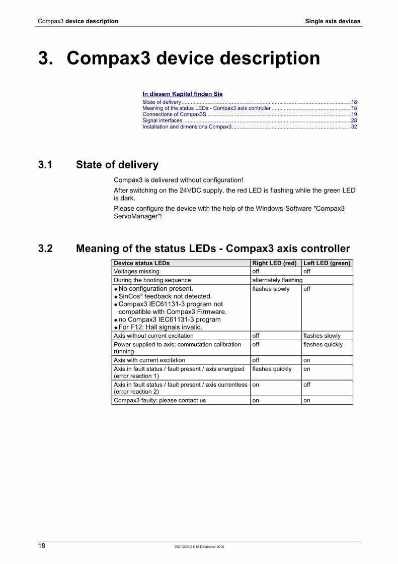
3.1 State of delivery Compax3 is delivered without configuration! After switching on the 24VDC supply, the red LED is flashing while the green LED is dark. Please configure the device with the help of the Windows-Software "Compax3 ServoManager"!
3.2 Meaning of the status LEDs - Compax3 axis controller Device status LEDs Right LED (red) Left LED (green) Voltages missing off off During the booting sequence alternately flashing No configuration present. SinCos© feedback not detected. Compax3 IEC61131-3 program not
compatible with Compax3 Firmware. no Compax3 IEC61131-3 program For F12: Hall signals invalid.
flashes slowly off
Axis without current excitation off flashes slowly Power supplied to axis; commutation calibration running
off flashes quickly
Axis with current excitation off on Axis in fault status / fault present / axis energized (error reaction 1)
flashes quickly on
Axis in fault status / fault present / axis currentless (error reaction 2)
on off
Compax3 faulty: please contact us on on
3. Compax3 device description

Parker EME Compax3 device description
192-120102 N16 December 2010 19
3.3 Connections of Compax3S In diesem Kapitel finden Sie Compax3S connectors .................................................................................................... 19 Connector and pin assignment C3S................................................................................. 20 Control voltage 24VDC / enable connector X4 C3S ......................................................... 22 Motor / Motor brake (C3S connector X3) ......................................................................... 23 Compax3Sxxx V2 ............................................................................................................ 24 Compax3Sxxx V4 ............................................................................................................ 26
3.3.1. Compax3S connectors
X4
X10
X20
X21
X22
X24
X23
S24
X12
X13
X11
X3
X2
X1
LED3
LED2LED1
X1 AC Supply X20 HEDA in (Option) X2 Ballast / DC power voltage X21 HEDA out (Option) X3 Motor / Brake X22 Inputs Outputs (Option M10/12) X4 24VDC / Enable X23/
X24 Bus (Option) Connector type
depends on the bus system!
X10 RS232/RS485 S24 bus settings X11 Analog/Encoder LED1 Device status LEDs X12 Inputs/Outputs LED2 HEDA LEDs X13 Motor position feedback LED3 Bus LEDs
Caution - Risk of Electric Shock!
Always switch devices off before wiring them! Dangerous voltages are still present until 10 min. after switching off the power supply.
Compax3 device description Single axis devices
20 192-120102 N16 December 2010
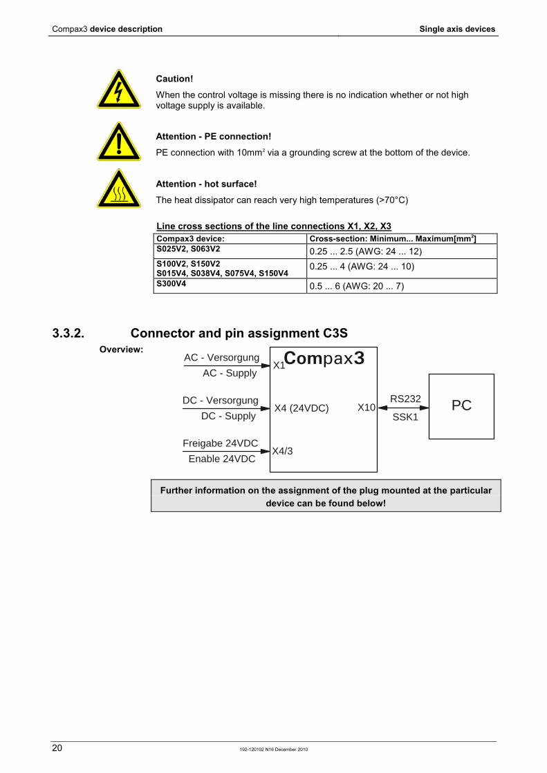
Caution!
When the control voltage is missing there is no indication whether or not high voltage supply is available.
Attention - PE connection!
PE connection with 10mm2 via a grounding screw at the bottom of the device.
Attention - hot surface!
The heat dissipator can reach very high temperatures (>70°C) Line cross sections of the line connections X1, X2, X3 Compax3 device: Cross-section: Minimum... Maximum[mm2] S025V2, S063V2 0.25 ... 2.5 (AWG: 24 ... 12) S100V2, S150V2 S015V4, S038V4, S075V4, S150V4
0.25 ... 4 (AWG: 24 ... 10)
S300V4 0.5 ... 6 (AWG: 20 ... 7)
3.3.2. Connector and pin assignment C3S
AC - Versorgung
AC - SupplyX1
X10DC - Versorgung
DC - SupplyX4 (24VDC)
Freigabe 24VDC
Enable 24VDCX4/3
RS232
SSK1PC
Compax3
Further information on the assignment of the plug mounted at the particular device can be found below!
Overview:
Parker EME Compax3 device description
192-120102 N16 December 2010 21
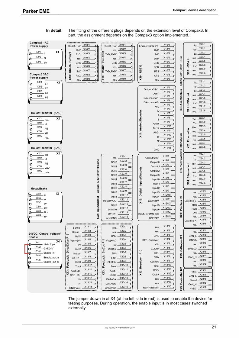
The fitting of the different plugs depends on the extension level of Compax3. In part, the assignment depends on the Compax3 option implemented.
X13/1
X13/2
X13/3
X13/4
X13/5
X13/6
X13/7
X13/8
X13/9
X13/10
X13/11
X13/12
X13/13
X13/14
X13/15
X11:
Ana
log/
Enco
der
X12:
Dig
ital
Inpu
ts/O
utpu
ts
X10/2RxDX10/3TxDX10/4DTRX10/5GNDX10/6DSRX10/7RTSX10/8CTSX10/9+5VX1
0: R
S232
X12/1
X12/2
X12/3
X12/4
X12/5
X12/6
X12/7
X12/8
X12/9
X12/10
X12/11
X12/12
X12/13
X12/14
X12/15
res.
res.
GND
REF+Resolver
+5V
CLKfbk
SIN-
SIN+
CLKfbk/
Tmot
COS-
COS+
res.
res.
REF-Resolver
X13:
Res
olve
r F1
0
X10/1EnableRS232 0V
Output+24V
Output 0
Output 1
Output 2
Output 3
Input 0
Input 1
Input 2
Input 3
Input 4
Input+24V
Input 5
Input 6
Input 7 or (MN-INI)
GND24V
Output +24V
Ain1-
D/A-channel1
D/A-channel0
+5V
A/
A
B
Ain0+
Ain1+
Ain0-
B/
N/
N
GND
X11/1
X11/2
X11/3
X11/4
X11/5
X11/6
X11/7
X11/8
X11/9
X11/10
X11/11
X11/12
X11/13
X11/14
X11/15
Sense-
Sense+
Hall1
Vcc(+5V)
+5V
Hall2
Sin-/A-
Sin+/A+
Hall3
Tmot
COS-/B-
COS+/B+
N+
N-
GND(Vcc)
X13/1
X13/2
X13/3
X13/4
X13/5
X13/6
X13/7
X13/8
X13/9
X13/10
X13/11
X13/12
X13/13
X13/14
X13/15
X13/1
X13/2
X13/3
X13/4
X13/5
X13/6
X13/7
X13/8
X13/9
X13/10
X13/11
X13/12
X13/13
X13/14
X13/15
res.
res.
Vcc(+8V)
+5V
CLKfbk
SIN-
SIN+
CLKfbk/
Tmot
COS-
COS+
DATAfbk
DATAfbk/
GND(Vcc)
GND
X13:
Fee
dbac
k S
inC
os F
11
X13:
Fee
dbac
k D
irect
Driv
e F1
2
X23/6res.X23/7CAN_HX23/8res.X23/9res.
X23:
CA
Nop
en I2
1
X23/1res.X23/2CAN_LX23/3GNDfbX23/4res.X23/5SHIELD
X1/4
L2X1/2
L3X1/3
PE
X1/1L1 X1
X1/1L
X1/2 NX1/3 PE
X1
Compax3 1ACPower supply
Compax3 3ACPower supply
X10/2
X10/3
X10/4
X10/5
X10/6
X10/7
X10/8
X10/9
X10/1
RxD
TxD/
res.
GND
res.
TxD
RxD/
+5V
RS485 +5V
X10:
RS4
85 v
ierd
raht
X10/2
X10/3
X10/4
X10/5
X10/6
X10/7
X10/8
X10/9
X10/1
res.
TxD_RxD/
res.
GND
res.
TxD_RxD/
res.
+5V
RS485 +5V
X10:
RS4
85 z
wei
drah
t
-R
PE
+R
+HV
-HV
X2/1
X2/2X2/3
X2/4
X2/5
X2
Ballast resistor (3AC)
X3/2V
X3/1U
X3/3W
PEX3/4
Br+X3/5
Br-X3/6
X3
Motor/Brake
GND24V
Enable_in
+24V Input
Enable_out_a
Enable_out_b
X4/1
X4/2X4/3
X4/4
X4/5
X4
24VDC Control voltage/Enable
-R
PE
res.
+R
res.
X2/1
X2/2X2/3
X2/4
X2/5
X2
Ballast resistor (1AC)
HED
A-m
otio
nbus
op
tion
M11
(M10
=+I/O
s)
X20/6Lx/X20/7res.X20/8res.X2
0: H
EDA
in
X20/1RxX20/2Rx/X20/3LxX20/4res.X20/5res.
X21/6Lx/X21/7res.X21/8res.
X21/1TxX21/2Tx/X21/3LxX21/4res.X21/5res.
X21:
HED
A o
ut
X23:
Dev
iceN
et I2
2
X23/1-VDCX23/2CAN_LX23/3ShieldX23/4CAN_HX23/5+VDC
X22/1
X22/2
X22/3
X22/4
X22/5
X22/6
X22/7
X22/8
X22/9
X22/10
X22/11
X22/12
X22/13
X22/14
X22/15
res.
O0/I0
O1/I1
O2/I2
O3/I3
O4/I4
O5/I5
O6/I6
O7/I7
O8/I8
Input24VDC
O9/I9
O10/I10
O11/I11
InputGNDX22:
Inpu
t/Out
put
opt
ion
M12
(M10
=+H
ED
A)
X23/6+5VX23/7res.X23/8Data line-AX23/9res.
X23:
Pro
fibus
I20
X23/1res.X23/2res.X23/3Data line-BX23/4RTSX23/5GND
Ethe
rnet
Pow
erlin
k In
terf
ace
I30
X23/6Rx-X23/7res.X23/8res.X2
3: E
ther
net i
n
X23/1Tx+X23/2Tx-X23/3Rx+X23/4res.X23/5res.
X24/6Rx-X24/7res.X24/8res.X2
4: E
ther
net o
ut
X24/1Tx+X24/2Tx-X24/3Rx+X24/4res.X24/5res.
The jumper drawn in at X4 (at the left side in red) is used to enable the device for testing purposes. During operation, the enable input is in most cases switched externally.
In detail:

Compax3 device description Single axis devices
22 192-120102 N16 December 2010
3.3.3. Control voltage 24VDC / enable connector X4 C3S PIN Description
Line cross sections: minimum: 0.25mm2 maximum: 2.5mm2 (AWG: 24 ... 12)
1 +24V (supply) 2 Gnd24V 3 Enable_in 4 Enable_out_a 5 Enable_out_b
Control voltage 24VDC Compax3S and Compax3H Controller type Compax3 Voltage range 21 - 27VDC Current drain of the device 0.8 A Total current drain 0.8 A + Total load of the digital outputs + current
for the motor holding brake Ripple 0.5Vpp Requirement according to safe extra low voltage (SELV)
yes
Short-circuit proof conditional (internally protected with 3.15AT) Hardware - enable (input X4/3 = 24VDC) This input is used as safety interrupt for the power output stage. Tolerance range: 18.0V - 33.6V / 720Ω
"Safe torque off (X4/3=0V) For implementation of the "safety torque off" safety feature in accordance with the “protection against unexpected start-up” described in EN1037. Observe instructions in the corresponding chapter with the circuitry examples! The energy supply to the drive is reliably shut off, the motor has no torque. A relay contact is located between X4/4 and X4/5 (normally closed contact) Enable_out_a - Enable_out_b Power output
stage is Contact opened activated Contact closed disabled
Series connection of these contacts permits certain determination of whether all drives are de-energized.
Relay contact data: Switching voltage (AC/DC): 100mV - 60V Switching current: 10mA - 0.3A Switching power: 1mW...7W
Parker EME Compax3 device description
192-120102 N16 December 2010 23
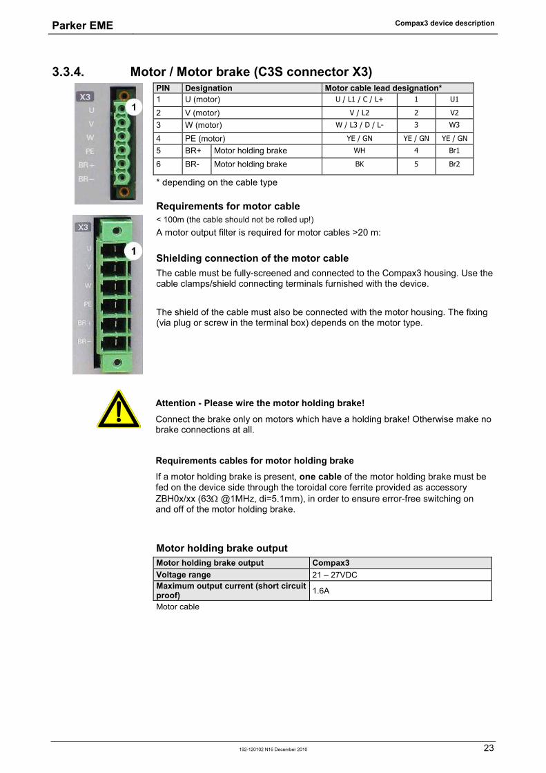
3.3.4. Motor / Motor brake (C3S connector X3) PIN Designation Motor cable lead designation* 1 U (motor) U / L1 / C / L+ 1 U1
2 V (motor) V / L2 2 V2
3 W (motor) W / L3 / D / L- 3 W3
4 PE (motor) YE / GN YE / GN YE / GN
5 BR+ Motor holding brake WH 4 Br1
6 BR- Motor holding brake BK 5 Br2
* depending on the cable type
Requirements for motor cable < 100m (the cable should not be rolled up!) A motor output filter is required for motor cables >20 m:
Shielding connection of the motor cable The cable must be fully-screened and connected to the Compax3 housing. Use the cable clamps/shield connecting terminals furnished with the device. The shield of the cable must also be connected with the motor housing. The fixing (via plug or screw in the terminal box) depends on the motor type.
Attention - Please wire the motor holding brake!
Connect the brake only on motors which have a holding brake! Otherwise make no brake connections at all.
Requirements cables for motor holding brake
If a motor holding brake is present, one cable of the motor holding brake must be fed on the device side through the toroidal core ferrite provided as accessory ZBH0x/xx (63Ω @1MHz, di=5.1mm), in order to ensure error-free switching on and off of the motor holding brake.
Motor holding brake output Motor holding brake output Compax3 Voltage range 21 – 27VDC Maximum output current (short circuit proof) 1.6A
Motor cable
Compax3 device description Single axis devices
24 192-120102 N16 December 2010
3.3.5. Compax3Sxxx V2 In diesem Kapitel finden Sie Main voltage supply C3S connector X1 ........................................................................... 24 Braking resistor / high voltage DC C3S connector X2 ..................................................... 25
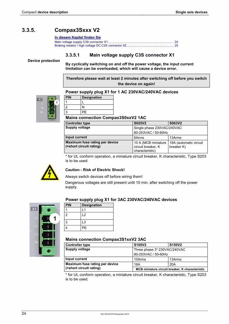
3.3.5.1 Main voltage supply C3S connector X1
By cyclically switching on and off the power voltage, the input current limitation can be overloaded, which will cause a device error.
Therefore please wait at least 2 minutes after switching off before you switch the device on again!
Power supply plug X1 for 1 AC 230VAC/240VAC devices PIN Designation 1 L 2 N 3 PE
Mains connection Compax3S0xxV2 1AC Controller type S025V2 S063V2 Supply voltage Single phase 230VAC/240VAC
80-253VAC / 50-60Hz Input current 6Arms 13Arms Maximum fuse rating per device (=short circuit rating)
10 A (MCB miniature circuit breaker, K characteristic)
16A (automatic circuit breaker K)
* for UL conform operation, a miniature circuit breaker, K characteristic, Type S203 is to be used.
Caution - Risk of Electric Shock!
Always switch devices off before wiring them! Dangerous voltages are still present until 10 min. after switching off the power supply.
Power supply plug X1 for 3AC 230VAC/240VAC devices PIN Designation 1 L1 2 L2
3 L3 4 PE
Mains connection Compax3S1xxV2 3AC Controller type S100V2 S150V2 Supply voltage Three phase 3* 230VAC/240VAC
80-253VAC / 50-60Hz Input current 10Arms 13Arms Maximum fuse rating per device (=short circuit rating)
16A 20A MCB miniature circuit breaker, K characteristic
* for UL conform operation, a miniature circuit breaker, K characteristic, Type S203 is to be used.
Device protection
Parker EME Compax3 device description
192-120102 N16 December 2010 25
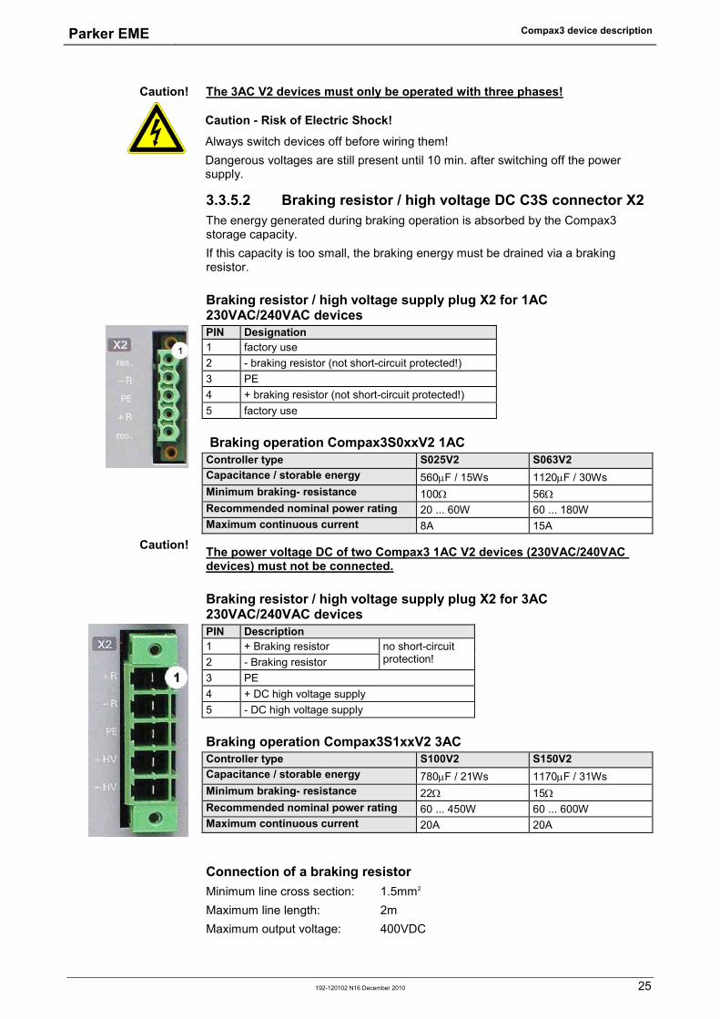
The 3AC V2 devices must only be operated with three phases!
Caution - Risk of Electric Shock!
Always switch devices off before wiring them! Dangerous voltages are still present until 10 min. after switching off the power supply.
3.3.5.2 Braking resistor / high voltage DC C3S connector X2 The energy generated during braking operation is absorbed by the Compax3 storage capacity. If this capacity is too small, the braking energy must be drained via a braking resistor.
Braking resistor / high voltage supply plug X2 for 1AC 230VAC/240VAC devices PIN Designation 1 factory use 2 - braking resistor (not short-circuit protected!) 3 PE 4 + braking resistor (not short-circuit protected!) 5 factory use
Braking operation Compax3S0xxV2 1AC Controller type S025V2 S063V2 Capacitance / storable energy 560µF / 15Ws 1120µF / 30Ws Minimum braking- resistance 100Ω 56Ω Recommended nominal power rating 20 ... 60W 60 ... 180W Maximum continuous current 8A 15A
The power voltage DC of two Compax3 1AC V2 devices (230VAC/240VAC devices) must not be connected.
Braking resistor / high voltage supply plug X2 for 3AC 230VAC/240VAC devices PIN Description 1 + Braking resistor no short-circuit
protection! 2 - Braking resistor 3 PE 4 + DC high voltage supply 5 - DC high voltage supply
Braking operation Compax3S1xxV2 3AC Controller type S100V2 S150V2 Capacitance / storable energy 780µF / 21Ws 1170µF / 31Ws Minimum braking- resistance 22Ω 15Ω Recommended nominal power rating 60 ... 450W 60 ... 600W Maximum continuous current 20A 20A
Connection of a braking resistor Minimum line cross section: 1.5mm2 Maximum line length: 2m Maximum output voltage: 400VDC
Caution!
Caution!

Compax3 device description Single axis devices
26 192-120102 N16 December 2010
3.3.6. Compax3Sxxx V4 In diesem Kapitel finden Sie Power supply connector X1 for 3AC 400VAC/480VAC-C3S devices ............................... 26 Braking resistor / high voltage supply connector X2 for 3AC 400VAC/480VAC_C3S devices ....................................................................................................................................... 27 Connection of the power voltage of 2 C3S 3AC devices .................................................. 27
3.3.6.1 Power supply connector X1 for 3AC 400VAC/480VAC-C3S devices
By cyclically switching on and off the power voltage, the input current limitation can be overloaded, which will cause a device error.
Therefore please wait at least 2 minutes after switching off before you switch the device on again!
PIN Designation 1 L1 2 L2 3 L3 4 PE
Mains connection Compax3SxxxV4 3AC Controller type S015V4 S038V4 S075V4 S150V4 S300V4 Supply voltage Three phase 3*400VAC/480VAC
80-528VAC / 50-60Hz Input current 3Aeff 6Arms 10Arms 16Arms 22Arms Maximum fuse rating per device(=short circuit rating)
6A 10A 16A 20A 25A MCB miniature circuit breaker, K characteristic D*
* for UL conform operation, a miniature circuit breaker, K characteristic, Type S203 is to be used.
The 3AC V4 devices must only be operated with three phases!
Caution - Risk of Electric Shock!
Always switch devices off before wiring them! Dangerous voltages are still present until 10 min. after switching off the power supply.
Device protection
Caution!
Parker EME Compax3 device description
192-120102 N16 December 2010 27
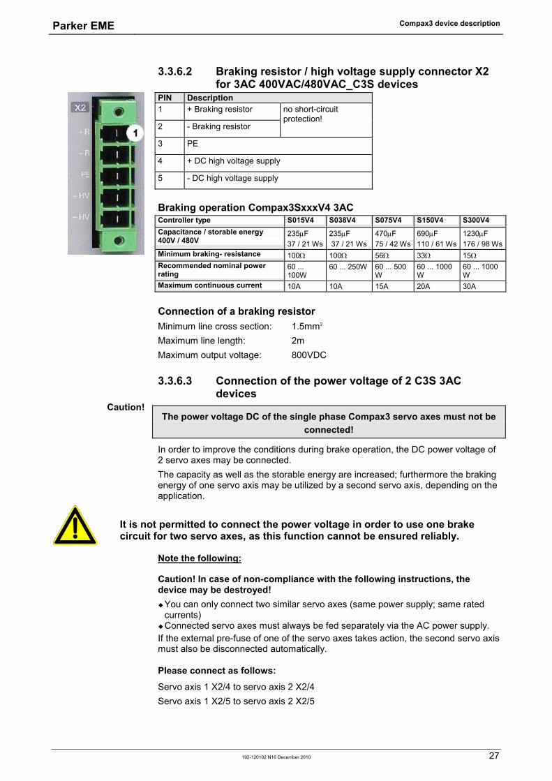
3.3.6.2 Braking resistor / high voltage supply connector X2 for 3AC 400VAC/480VAC_C3S devices
PIN Description 1 + Braking resistor no short-circuit
protection! 2 - Braking resistor
3 PE
4 + DC high voltage supply
5 - DC high voltage supply
Braking operation Compax3SxxxV4 3AC Controller type S015V4 S038V4 S075V4 S150V4 S300V4 Capacitance / storable energy 400V / 480V
235µF 37 / 21 Ws
235µF 37 / 21 Ws
470µF 75 / 42 Ws
690µF 110 / 61 Ws
1230µF 176 / 98 Ws
Minimum braking- resistance 100Ω 100Ω 56Ω 33Ω 15Ω Recommended nominal power rating
60 ... 100W
60 ... 250W 60 ... 500 W
60 ... 1000 W
60 ... 1000 W
Maximum continuous current 10A 10A 15A 20A 30A
Connection of a braking resistor Minimum line cross section: 1.5mm2 Maximum line length: 2m Maximum output voltage: 800VDC
3.3.6.3 Connection of the power voltage of 2 C3S 3AC devices
The power voltage DC of the single phase Compax3 servo axes must not be connected!
In order to improve the conditions during brake operation, the DC power voltage of 2 servo axes may be connected. The capacity as well as the storable energy are increased; furthermore the braking energy of one servo axis may be utilized by a second servo axis, depending on the application.
It is not permitted to connect the power voltage in order to use one brake circuit for two servo axes, as this function cannot be ensured reliably.
Note the following:
Caution! In case of non-compliance with the following instructions, the device may be destroyed! You can only connect two similar servo axes (same power supply; same rated
currents) Connected servo axes must always be fed separately via the AC power supply. If the external pre-fuse of one of the servo axes takes action, the second servo axis must also be disconnected automatically.
Please connect as follows:
Servo axis 1 X2/4 to servo axis 2 X2/4 Servo axis 1 X2/5 to servo axis 2 X2/5
Caution!

Compax3 device description Single axis devices
28 192-120102 N16 December 2010
3.4 Signal interfaces In diesem Kapitel finden Sie RS232/RS485 interface (plug X10) .................................................................................. 28 Resolver / feedback (plug X13) ........................................................................................ 29 Analogue / encoder (plug X11) ........................................................................................ 30 Digital inputs/outputs (plug X12) ...................................................................................... 31
3.4.1. RS232/RS485 interface (plug X10) Interface selectable by contact functions assignment of X10/1: X10/1=0V RS232 X10/1=5V RS485 PIN X10 RS232 (Sub D) 1 (Enable RS232) 0V 2 RxD 3 TxD 4 DTR 5 GND 6 DSR 7 RTS 8 CTS 9 +5V
RS485 2-wire PIN X10 RS485 2-wire Sub D
Pin 1 and 9 externally jumpered 1 Enable RS485 (+5V) 2 res. 3 TxD_RxD/ 4 res. 5 GND 6 res. 7 TxD_RxD 8 res. 9 +5V
RS485 4-wire PIN X10 RS485 4-wire Sub D
Pin 1 and 9 externally jumpered 1 Enable RS485 (+5V) 2 RxD 3 TxD/ 4 res. 5 GND 6 res. 7 TxD 8 RxD/ 9 +5V
USB - RS232/RS485 converter
The following USB - RS232 converters were tested: ATEN UC 232A USB GMUS-03 (available under several company names) USB / RS485: Moxa Uport 1130
http://www.moxa.com/product/UPort_1130.htm Ethernet/RS232/RS485: NetCom 113 http://www.vscom.de/666.htm
If X10 at the control unit is used, the programming interface as well as the external device status LEDs are out of order due to the removal of the X10
jumper (VBK17/01)!
Note on Compax3H
Parker EME Compax3 device description
192-120102 N16 December 2010 29
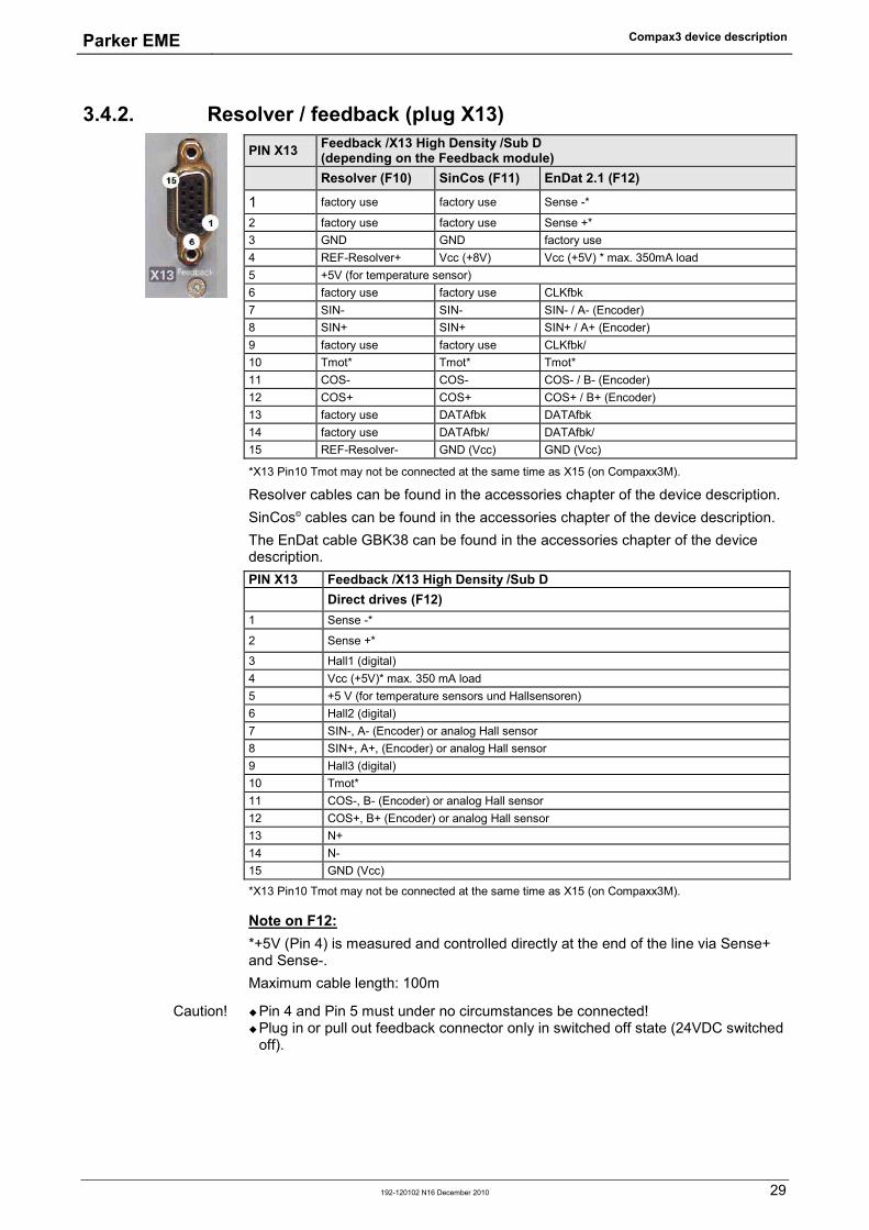
3.4.2. Resolver / feedback (plug X13) PIN X13 Feedback /X13 High Density /Sub D
(depending on the Feedback module) Resolver (F10) SinCos (F11) EnDat 2.1 (F12)
1 factory use factory use Sense -*
2 factory use factory use Sense +* 3 GND GND factory use 4 REF-Resolver+ Vcc (+8V) Vcc (+5V) * max. 350mA load 5 +5V (for temperature sensor) 6 factory use factory use CLKfbk 7 SIN- SIN- SIN- / A- (Encoder) 8 SIN+ SIN+ SIN+ / A+ (Encoder) 9 factory use factory use CLKfbk/ 10 Tmot* Tmot* Tmot* 11 COS- COS- COS- / B- (Encoder) 12 COS+ COS+ COS+ / B+ (Encoder) 13 factory use DATAfbk DATAfbk 14 factory use DATAfbk/ DATAfbk/ 15 REF-Resolver- GND (Vcc) GND (Vcc) *X13 Pin10 Tmot may not be connected at the same time as X15 (on Compaxx3M).
Resolver cables can be found in the accessories chapter of the device description. SinCos© cables can be found in the accessories chapter of the device description. The EnDat cable GBK38 can be found in the accessories chapter of the device description. PIN X13 Feedback /X13 High Density /Sub D Direct drives (F12) 1 Sense -*
2 Sense +*
3 Hall1 (digital) 4 Vcc (+5V)* max. 350 mA load 5 +5 V (for temperature sensors und Hallsensoren) 6 Hall2 (digital) 7 SIN-, A- (Encoder) or analog Hall sensor 8 SIN+, A+, (Encoder) or analog Hall sensor 9 Hall3 (digital) 10 Tmot* 11 COS-, B- (Encoder) or analog Hall sensor 12 COS+, B+ (Encoder) or analog Hall sensor 13 N+ 14 N- 15 GND (Vcc) *X13 Pin10 Tmot may not be connected at the same time as X15 (on Compaxx3M). Note on F12: *+5V (Pin 4) is measured and controlled directly at the end of the line via Sense+ and Sense-. Maximum cable length: 100m
Pin 4 and Pin 5 must under no circumstances be connected! Plug in or pull out feedback connector only in switched off state (24VDC switched
off).
Caution!

Compax3 device description Single axis devices
30 192-120102 N16 December 2010
3.4.3. Analogue / encoder (plug X11) PIN X11 Reference
High Density Sub D Encoders SSI 1 +24V (output) max. 70mA 2 Ain1 -; analog input - (14Bits; max. +/-10V) 3 D/A monitor channel 1 (±10V, 8-bit resolution) 4 D/A monitor channel 0 (±10V, 8-bit resolution) 5 +5 V (output for encoder) max. 150 mA 6 - Input: steps RS422 (5V - level) A/ (Input / -simulation) Clock- 7 + Input: steps RS422 (5V - level) A/ (Input / -simulation) Clock+ 8 + Input: direction RS422 (5V - level) B Input / -simulation) 9 Ain0 +: analog input + (14Bits; max. +/-10V) 10 Ain1 +: analog input + (14Bits; max. +/-10V) 11 Ain0 -: analog input- (14Bits; max. +/-10V) 12 - Input: direction RS422 (5V - level) B/ input / -simulation) 13 factory use N/ input / -simulation) DATA- 14 factory use N input / -simulation) DATA+ 15 GND Technical Data X11 (see on page 38)
3.4.3.1 Wiring of analog interfaces Output Input
Compax3
+/-10V/1mA(max: 3mA)
X11/3
X11/15
332ΩX11/4
10nF
2.2KΩ
10KΩAin+
2.2KΩ
X11/9
10KΩ
10nF
Ain-X11/11
2.5V
Compax3
Perform an offset adjustment!
Structure image of the internal signal processing of the analog inputs
Ain1 (X11/10 and X11/2) has the same wiring!
3.4.3.2 Connections of the encoder interface
10nF
+5V
121ΩA
1KΩ
1KΩ
GND
A B N
RS422Transceiver
B N
Compax3
The input connection is available in triple (for A & /A, B & /B, N & /N)
Parker EME Compax3 device description
192-120102 N16 December 2010 31
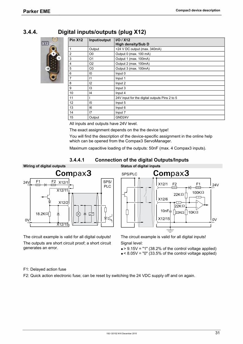
3.4.4. Digital inputs/outputs (plug X12) Pin X12 Input/output I/O / X12
High density/Sub D 1 Output +24 V DC output (max. 340mA) 2 O0 Output 0 (max. 100 mA) 3 O1 Output 1 (max. 100mA) 4 O2 Output 2 (max. 100mA) 5 O3 Output 3 (max. 100mA) 6 I0 Input 0 7 I1 Input 1 8 I2 Input 2 9 I3 Input 3 10 I4 Input 4 11 I 24V input for the digital outputs Pins 2 to 5 12 I5 Input 5 13 I6 Input 6 14 I7 Input 7 15 Output GND24V All inputs and outputs have 24V level. The exact assignment depends on the the device type! You will find the description of the device-specific assignment in the online help which can be opened from the Compax3 ServoManager. Maximum capacitive loading of the outputs: 50nF (max. 4 Compax3 inputs).
3.4.4.1 Connection of the digital Outputs/Inputs Wiring of digital outputs Status of digital inputs
24V
0V
X12/2
18.2KΩ
X12/15
X12/1
X12/11
SPS/PLC
F2F1
Compax3
24V
0V
100KΩ
X12/1
X12/6
X12/15
10KΩ22KΩ
22KΩ
22KΩ
SPS/PLC
F2 F1
10nF
Compax3
The circuit example is valid for all digital outputs! The outputs are short circuit proof; a short circuit generates an error.
The circuit example is valid for all digital inputs! Signal level: > 9.15V = "1" (38.2% of the control voltage applied) < 8.05V = "0" (33.5% of the control voltage applied)
F1: Delayed action fuse F2: Quick action electronic fuse; can be reset by switching the 24 VDC supply off and on again.
Compax3 device description Single axis devices
32 192-120102 N16 December 2010
3.5 Installation and dimensions Compax3 In diesem Kapitel finden Sie Mounting and dimensions Compax3S0xxV2 .................................................................... 32 Mounting and dimensions Compax3S100V2 and S0xxV4................................................ 33 Mounting and dimensions Compax3S150V2 and S150V4 ............................................... 34 Mounting and dimensions Compax3S300V4 ................................................................... 35
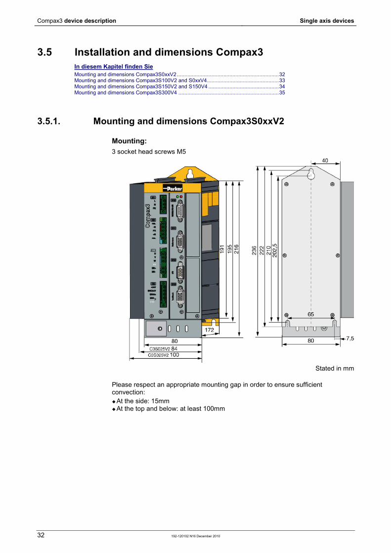
3.5.1. Mounting and dimensions Compax3S0xxV2
Mounting: 3 socket head screws M5
Stated in mm
Please respect an appropriate mounting gap in order to ensure sufficient convection: At the side: 15mm At the top and below: at least 100mm
Parker EME Compax3 device description
192-120102 N16 December 2010 33
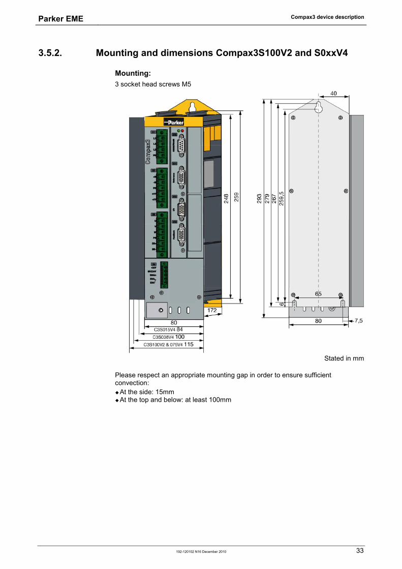
3.5.2. Mounting and dimensions Compax3S100V2 and S0xxV4
Mounting: 3 socket head screws M5
Stated in mm
Please respect an appropriate mounting gap in order to ensure sufficient convection: At the side: 15mm At the top and below: at least 100mm
Compax3 device description Single axis devices
34 192-120102 N16 December 2010
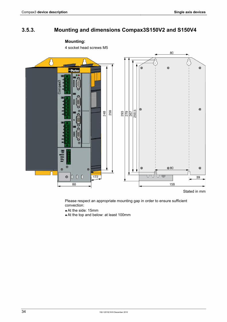
3.5.3. Mounting and dimensions Compax3S150V2 and S150V4
Mounting: 4 socket head screws M5
Stated in mm
Please respect an appropriate mounting gap in order to ensure sufficient convection: At the side: 15mm At the top and below: at least 100mm

Parker EME Compax3 device description
192-120102 N16 December 2010 35
3.5.4. Mounting and dimensions Compax3S300V4
Mounting: 4 socket head screws M5
Stated in mm
Please respect an appropriate mounting gap in order to ensure sufficient convection: At the side: 15mm At the top and below: at least 100mm
Compax3S300V4 is force-ventilated via a fan integrated into the heat dissipator!

Technical Characteristics Single axis devices
36 192-120102 N16 December 2010
Mains connection Compax3S0xxV2 1AC Controller type S025V2 S063V2 Supply voltage Single phase 230VAC/240VAC
80-253VAC / 50-60Hz Input current 6Arms 13Arms Maximum fuse rating per device (=short circuit rating)
10 A (MCB miniature circuit breaker, K characteristic)
16A (automatic circuit breaker K)
Mains connection Compax3S1xxV2 3AC Controller type S100V2 S150V2 Supply voltage Three phase 3* 230VAC/240VAC
80-253VAC / 50-60Hz Input current 10Arms 13Arms Maximum fuse rating per device (=short circuit rating)
16A 20A MCB miniature circuit breaker, K characteristic
Mains connection Compax3SxxxV4 3AC Controller type S015V4 S038V4 S075V4 S150V4 S300V4 Supply voltage Three phase 3*400VAC/480VAC
80-528VAC / 50-60Hz Input current 3Aeff 6Arms 10Arms 16Arms 22Arms Maximum fuse rating per device(=short circuit rating)
6A 10A 16A 20A 25A MCB miniature circuit breaker, K characteristic D*
Control voltage 24VDC Compax3S and Compax3H Controller type Compax3 Voltage range 21 - 27VDC Current drain of the device 0.8 A Total current drain 0.8 A + Total load of the digital outputs + current
for the motor holding brake Ripple 0.5Vpp Requirement according to safe extra low voltage (SELV)
yes
Short-circuit proof conditional (internally protected with 3.15AT)
Output data Compax3S0xx at 1*230VAC/240VAC Controller type S025V2 S063V2 Output voltage 3x 0-240V 3x 0-240V Nominal output current 2.5Arms 6.3Arms Pulse current for 5s 5.5Arms 12.6Arms Power 1kVA 2.5kVA Switching frequency 16kHz 16kHz Power loss for In 30W 60W
4. Technical Characteristics
Parker EME Technical Characteristics
192-120102 N16 December 2010 37
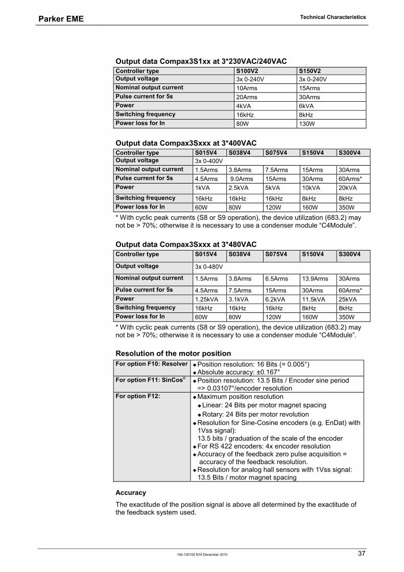
Output data Compax3S1xx at 3*230VAC/240VAC Controller type S100V2 S150V2 Output voltage 3x 0-240V 3x 0-240V Nominal output current 10Arms 15Arms Pulse current for 5s 20Arms 30Arms Power 4kVA 6kVA Switching frequency 16kHz 8kHz Power loss for In 80W 130W
Output data Compax3Sxxx at 3*400VAC Controller type S015V4 S038V4 S075V4 S150V4 S300V4 Output voltage 3x 0-400V Nominal output current 1.5Arms 3.8Arms 7.5Arms 15Arms 30Arms Pulse current for 5s 4.5Arms 9.0Arms 15Arms 30Arms 60Arms* Power 1kVA 2.5kVA 5kVA 10kVA 20kVA Switching frequency 16kHz 16kHz 16kHz 8kHz 8kHz Power loss for In 60W 80W 120W 160W 350W
* With cyclic peak currents (S8 or S9 operation), the device utilization (683.2) may not be > 70%; otherwise it is necessary to use a condenser module “C4Module”.
Output data Compax3Sxxx at 3*480VAC Controller type S015V4 S038V4 S075V4 S150V4 S300V4
Output voltage 3x 0-480V
Nominal output current 1.5Arms 3.8Arms 6.5Arms 13.9Arms 30Arms
Pulse current for 5s 4.5Arms 7.5Arms 15Arms 30Arms 60Arms* Power 1.25kVA 3.1kVA 6.2kVA 11.5kVA 25kVA Switching frequency 16kHz 16kHz 16kHz 8kHz 8kHz Power loss for In 60W 80W 120W 160W 350W
* With cyclic peak currents (S8 or S9 operation), the device utilization (683.2) may not be > 70%; otherwise it is necessary to use a condenser module “C4Module”.
Resolution of the motor position For option F10: Resolver Position resolution: 16 Bits (= 0.005°)
Absolute accuracy: ±0.167° For option F11: SinCos© Position resolution: 13.5 Bits / Encoder sine period
=> 0.03107°/encoder resolution For option F12: Maximum position resolution
Linear: 24 Bits per motor magnet spacing Rotary: 24 Bits per motor revolution
Resolution for Sine-Cosine encoders (e.g. EnDat) with 1Vss signal): 13.5 bits / graduation of the scale of the encoder
For RS 422 encoders: 4x encoder resolution Accuracy of the feedback zero pulse acquisition =
accuracy of the feedback resolution. Resolution for analog hall sensors with 1Vss signal:
13.5 Bits / motor magnet spacing
Accuracy
The exactitude of the position signal is above all determined by the exactitude of the feedback system used.
Technical Characteristics Single axis devices
38 192-120102 N16 December 2010
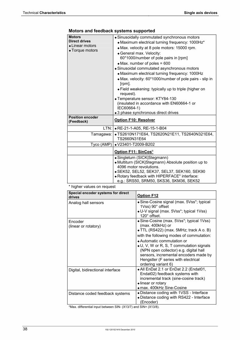
Motors and feedback systems supported Motors Direct drives Linear motors Torque motors
Sinusoidally commutated synchronous motors Maximum electrical turning frequency: 1000Hz* Max. velocity at 8 pole motors: 15000 rpm. General max. Velocity:
60*1000/number of pole pairs in [rpm] Max. number of poles = 600
Sinusoidal commutated asynchronous motors Maximum electrical turning frequency: 1000Hz Max. velocity: 60*1000/number of pole pairs - slip in
[rpm]. Field weakening: typically up to triple (higher on
request). Temperature sensor: KTY84-130
(insulated in accordance with EN60664-1 or IEC60664-1)
3 phase synchronous direct drives Position encoder (Feedback) Option F10: Resolver
LTN: RE-21-1-A05, RE-15-1-B04 Tamagawa: TS2610N171E64, TS2620N21E11, TS2640N321E64,
TS2660N31E64 Tyco (AMP) V23401-T2009-B202
Option F11: SinCos©
Singleturn (SICK|Stegmann) Multiturn (SICK|Stegmann) Absolute position up to
4096 motor revolutions. SEK52, SEL52, SEK37, SEL37, SEK160, SEK90 Rotary feedback with HIPERFACE® interface:
e.g.: SRS50, SRM50, SKS36, SKM36, SEK52 * higher values on request Special encoder systems for direct drives Option F12
Analog hall sensors Sine-Cosine signal (max. 5Vss*; typical 1Vss) 90° offset
U-V signal (max. 5Vss*; typical 1Vss) 120° offset.
Encoder (linear or rotatory)
Sine-Cosine (max. 5Vss*; typical 1Vss) (max. 400kHz) or
TTL (RS422) (max. 5MHz; track A o. B) with the following modes of commutation: Automatic commutation or U, V, W or R, S, T commutation signals
(NPN open collector) e.g. digital hall sensors, incremental encoders made by Hengstler (F series with electrical ordering variant 6)
Digital, bidirectional interface All EnDat 2.1 or EnDat 2.2 (Endat01, Endat02) feedback systems with incremental track (sine-cosine track)
linear or rotary max. 400kHz Sine-Cosine
Distance coded feedback systems Distance coding with 1VSS - Interface Distance coding with RS422 - Interface
(Encoder) *Max. differential input between SIN- (X13/7) and SIN+ (X13/8).

Parker EME Technical Characteristics
192-120102 N16 December 2010 39
Motor holding brake output Motor holding brake output Compax3 Voltage range 21 – 27VDC Maximum output current (short circuit proof) 1.6A
Safety technology Compax3S Safe torque-off in accordance with EN ISO 13849: 2008, Category 3, PL d/e Certified. Test mark IFA 1003004
For implementation of the “protection against unexpected start-up” function described in EN1037.
Please note the circuitry examples.
Compax3S STO (=safe torque off) Nominal voltage of the inputs
24 V
Required isolation of the 24V control voltage
Grounded protective extra low voltage, PELV
Protection of the STO control voltage
1 A
Grouping of safety level STO switch-off via internal safety relay & digital input: PL e, PFHd=2.98E-8 STO switch-off via internal safety relay & fieldbus: PL d, PFHd=1.51E-7 A MTTFd=15 of the external PLC and STO cycles/year < 500 000 are assumed.
UL certification for Compax3S conform to UL: according to UL508C Certified E-File_No.: E235342 The UL certification is documented by a "UL" logo on the device (type specification plate).
“UL” logo:
Insulation requirements Enclosure rating Protection class in accordance with EN 60664-1 Protection against human contact with dangerous voltages In accordance with EN 61800-5-1
Overvoltage category Voltage category III in accordance with EN 60664-1
Degree of contamination Degree of contamination 2 in accordance with EN 60664-1 and EN 61800-5-1

Technical Characteristics Single axis devices
40 192-120102 N16 December 2010
Environmental conditions Compax3S and Compax3H General ambient conditions In accordance with EN 60 721-3-1 to 3-3
Climate (temperature/humidity/barometric pressure): Class 3K3
Permissible ambient temperature: Operation storage transport
0 to +45 °C class 3K3 –25 to +70 °C class 2K3 –25 to +70 °C class 2K3
Tolerated humidity: no condensation Operation storage transport
<= 85% class 3K3 <= 95% class 2K3 <= 95% class 2K3
(Relative humidity)
Elevation of operating site <=1000m above sea level for 100% load ratings <=2000m above sea level for 1% / 100m power reduction please inquire for greater elevations
Mechanic resonances: EN 60068-2-6 (sinusoidal excitation)
Sealing Protection type IP20 in accordance with EN 60 529
Cooling Compax3S and Compax3H Cooling mode: C3S025V2 ... S150V4: Convection
C3S300V4 & C3H: Forced air ventilation with fan in the heat dissipator Air flow rate:459m³/h (C3H)
Supply: C3S300V4, C3H050, C3H090 internal C3H125, C3H155 external 220/240VAC: 140W, 2.5µF, Stator - 62Ω Optionally on request: 110/120VAC: 130W, 10µF, Stator - 16Ω Circuit breaker:3A
EMC limit values Compax3S and Compax3H EMC interference emission Limit values in accordance with EN 61 800-3,
Limit value class C3/C4 without additional mains filter: Information on C2 limit value classes
EMC disturbance immunity Industrial area limit values in accordance with EN 61 800-3
EC directives and applied harmonized EC norms EC low voltage directive 2006/95/EG
EN 61800-5-1, Standard for electric power drives with settable speed; requirements to electric safety EN 60664-1, isolation coordinates for electrical equipment in low-voltage systems EN 60204-1, machinery norm partly applied
EC-EMC-directive 2004/108/EC
EN 61800-3, EMC standard Product standard for variable speed drives

Parker EME Technical Characteristics
192-120102 N16 December 2010 41
Detailed information on the technical data of the Compax3 devices can be found in the Help- or PDF-files of the individual Compax3 device types.
Index Single axis devices
42 192-120102 N16 December 2010
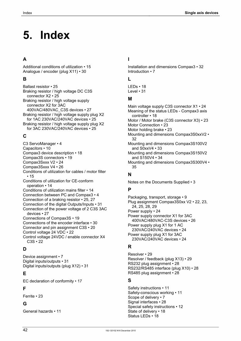
A
Additional conditions of utilization • 15 Analogue / encoder (plug X11) • 30
B
Ballast resistor • 25 Braking resistor / high voltage DC C3S
connector X2 • 25 Braking resistor / high voltage supply
connector X2 for 3AC 400VAC/480VAC_C3S devices • 27
Braking resistor / high voltage supply plug X2 for 1AC 230VAC/240VAC devices • 25
Braking resistor / high voltage supply plug X2 for 3AC 230VAC/240VAC devices • 25
C
C3 ServoManager • 4 Capacitors • 10 Compax3 device description • 18 Compax3S connectors • 19 Compax3Sxxx V2 • 24 Compax3Sxxx V4 • 26 Conditions of utilization for cables / motor filter
• 15 Conditions of utilization for CE-conform
operation • 14 Conditions of utilization mains filter • 14 Connection between PC and Compax3 • 4 Connection of a braking resistor • 25, 27 Connection of the digital Outputs/Inputs • 31 Connection of the power voltage of 2 C3S 3AC
devices • 27 Connections of Compax3S • 19 Connections of the encoder interface • 30 Connector and pin assignment C3S • 20 Control voltage 24 VDC • 22 Control voltage 24VDC / enable connector X4
C3S • 22
D
Device assignment • 7 Digital inputs/outputs • 31 Digital inputs/outputs (plug X12) • 31
E
EC declaration of conformity • 17
F
Ferrite • 23
G
General hazards • 11
I Installation and dimensions Compax3 • 32 Introduction • 7
L
LEDs • 18 Level • 31
M
Main voltage supply C3S connector X1 • 24 Meaning of the status LEDs - Compax3 axis
controller • 18 Motor / Motor brake (C3S connector X3) • 23 Motor Connection • 23 Motor holding brake • 23 Mounting and dimensions Compax3S0xxV2 •
32 Mounting and dimensions Compax3S100V2
and S0xxV4 • 33 Mounting and dimensions Compax3S150V2
and S150V4 • 34 Mounting and dimensions Compax3S300V4 •
35
N
Notes on the Documents Supplied • 3
P
Packaging, transport, storage • 9 Plug assignment Compax3S0xx V2 • 22, 23,
24, 25, 28, 29 Power supply • 24 Power supply connector X1 for 3AC
400VAC/480VAC-C3S devices • 26 Power supply plug X1 for 1 AC
230VAC/240VAC devices • 24 Power supply plug X1 for 3AC
230VAC/240VAC devices • 24
R
Resolver • 29 Resolver / feedback (plug X13) • 29 RS232 plug assignment • 28 RS232/RS485 interface (plug X10) • 28 RS485 plug assignment • 28
S
Safety instructions • 11 Safety-conscious working • 11 Scope of delivery • 7 Signal interfaces • 28 Special safety instructions • 12 State of delivery • 18 Status LEDs • 18
5. Index

Parker EME Index
192-120102 N16 December 2010 43
Storage • 10
T
Technical Characteristics • 36 Toroidal core ferrite • 23 Type specification plate • 8
U
Usage in accordance with intended purpose • 11
USB - RS232 converter • 28
W
Warranty conditions • 13 Wiring of analog interfaces • 30
X
X1 • 24 X10 • 28 X11 • 30 X12 • 31 X13 • 29 X2 • 25 X3 • 23 X4 • 22
Index Single axis devices
44 192-120102 N16 December 2010