single blade diverter manual
DESCRIPTION
manual de diverterTRANSCRIPT

SINGLE BLADE DIVERTER MANUAL

i
TABLE OF CONTENTS
1 MANUAL OVERVIEW ......................................................................................... 1
1.1 MANUAL CONTENTS ........................................................................................................................ 1 1.2 STORAGE RECOMMENDATIONS .................................................................................................... 1 1.3 GENERAL INSTALLATION ................................................................................................................ 1 1.4 MAINTENANCE RECOMMENDATIONS ........................................................................................... 1 1.5 WARRANTY ........................................................................................................................................ 1
2 STORAGE RECOMMENDATIONS ..................................................................... 2
2.1 GENERAL REQUIREMENTS ............................................................................................................. 2 2.1 ELECTRICAL EQUIPMENT ............................................................................................................... 2 2.2 ACTUATORS ...................................................................................................................................... 3 2.3 ADDITIONAL REQUIREMENTS ........................................................................................................ 3
3 GENERAL INSTALLATION ................................................................................ 4
3.1 RECEIVING INSPECTION ................................................................................................................. 4 3.2 INSTALLATION WARNING ................................................................................................................ 4 3.3 GATE MOUNTING .............................................................................................................................. 4
3.3.1 Manually Operated Gates and Valves ................................................................................... 5 3.3.2 Pneumatically Operated Gates and Valves ........................................................................... 7 3.3.3 Hydraulically Operated Gates and Valves ............................................................................. 8 3.3.4 Electrically Operated Gates and Valves ................................................................................ 8
4 MAINTENANCE RECOMMENDATIONS ............................................................ 9
4.1 MAINTENANCE PROGRAM IMPORTANCE ..................................................................................... 9 4.2 WEAR PARTS .................................................................................................................................... 9 4.3 MAINTENANCE SCHEDULE ............................................................................................................. 9
4.3.1 Suggested Maintenance Schedule ...................................................................................... 10 4.3.2 Spare Part Installation Log ................................................................................................... 10
4.4 SAFETY PRECAUTIONS ................................................................................................................. 11 4.5 LUBRICATION .................................................................................................................................. 11
4.5.1 Flange Bearings ................................................................................................................... 11 4.5.2 Gear Boxes .......................................................................................................................... 11 4.5.3 Rod End Bearings ................................................................................................................ 11
4.6 FRL TRIO INSPECTION/MAINTENANCE ....................................................................................... 11 4.7 CYLINDER CUSHION ADJUSTMENT ............................................................................................. 12 4.8 SEAL REPLACEMENT ..................................................................................................................... 12
4.8.1 Shaft Seal Replacement ...................................................................................................... 13 4.8.2 Blade Seal Replacement ..................................................................................................... 14
4.9 BLADE REPLACEMENT .................................................................................................................. 15 4.10 MOUNTING BOLT INSPECTION ..................................................................................................... 17 4.11 MUFFLER SPEED CONTROLS ....................................................................................................... 17 4.12 TROUBLESHOOTING PNEUMATIC ACTUATORS ........................................................................ 17 4.13 HYDRAULIC SYSTEMS ................................................................................................................... 18
5 WARRANTY ...................................................................................................... 19
6 COMPONENTS ................................................................................................. 20

PEBCO® SINGLE BLADE DIVERTER MANUAL MANUAL OVERVIEW
1
1 MANUAL OVERVIEW
1.1 MANUAL CONTENTS
This Section of the manual will familiarize you with the contents of the other manual sections. This
manual is general in approach and may not include everything you want to know about the specifics
of your particular application. Specific technical information can be found on the drawings which are
a part of this manual.
If you have any questions, which cannot be answered by the written material provided, call PEBCO®
(270) 442-1996 or FAX (270) 442-5214.
1.2 STORAGE RECOMMENDATIONS
Section 2 covers recommendations for proper storage. In some cases, scheduling requirements or
construction delays result in the equipment being stored prior to installation. The guidelines
suggested in this Section are to aid the installer in selection of proper storage conditions. Because of
variability in site conditions/facilities, proper equipment storage/protection is the responsibility of the
purchaser or his agent.
PEBCO® is not responsible for any equipment damage which results from inadequate
storage/protection efforts.
1.3 GENERAL INSTALLATION
Section 3 covers installation and start-up procedures. Pay special attention to the !!! WARNING !!!
in Section 3.2. Generally, gates which are other than manually operated will revert to a fail-safe
position if power to the directional valve controlling the gate/valve is interrupted. Information is
included on installation of manually, pneumatically or hydraulically operated gates. Carefully consider
the information dealing with the installation of manual operators.
1.4 MAINTENANCE RECOMMENDATIONS
Section 4 covers recommendations for maintenance procedures. Information is presented on
gate/valve lubrication, pneumatic system maintenance, gate/valve seal adjustment or replacement
and pneumatic system troubleshooting. If the equipment you are installing is powered by a
PEBCO® supplied Hydraulic Power Unit, see the detailed separate manual covering hydraulic
system installation, operation and maintenance.
1.5 WARRANTY
Section 5 is PEBCO®’s Warranty to the purchaser of a Single Blade Diverter.

PEBCO® SINGLE BLADE DIVERTER MANUAL STORAGE RECOMMENDATIONS
2
2 STORAGE RECOMMENDATIONS
2.1 GENERAL REQUIREMENTS
If PEBCO® equipment is to be stored for a period of time longer than three weeks prior to installation,
the following procedures are recommended:
Equipment should be stored in enclosed areas. Indoor storage area should be clean and dry.
Storage should be off of the floor, preferably on skids or pallets.
Storage area should be free from rapid temperature changes. If necessary, an additional heat
source should be used.
Storage area should not subject equipment to vibration.
All interior and exterior surfaces of the spout must be thoroughly coated with Cosmoline. Any
unpainted surfaces, such as shafts, rollers, bearings, and pins should be given special
attention to ensure a thorough covering of Cosmoline.
Storage must be above any possible water or snow line.
All bearings must be fully charged with grease.
Periodic inspections should be made, checking the covering, any moisture present,
cleanliness and general appearance to ensure the absence of corrosion and the integrity of
the Cosmoline coating.
If outdoor storage is necessary, the equipment should be fully covered with weather-proof
material, vented so as not to trap moisture, but drip-proof so the water cannot enter or splash
up into it.
2.1 ELECTRICAL EQUIPMENT
All electrical device enclosures must be opened and coated with CRC Stor & Lube.
All electrical connections (terminations) must be coated with CRC Stor & Lube.
All electrical openings must be capped or plugged as necessary to be sealed to atmosphere.
Electrical junction boxes included with the equipment should be opened and any exposed
wire and terminations should be coated with CRC Stor & Lube. Open conduit connections
should be plugged or capped to atmosphere and the enclosure door should be securely
tightened to ensure sealing integrity.

PEBCO® SINGLE BLADE DIVERTER MANUAL STORAGE RECOMMENDATIONS
3
2.2 ACTUATORS
2.4.1 Hydraulic and Pneumatic Linear Actuators Hydraulic and pneumatic cylinders must be filled with 10 wt. oil. Assurances must be
taken to assure complete filling of the cylinders with oil. As an alternate, the hydraulic
cylinders may be filled with the same fluid the hydraulic system will operate with.
The hydraulic or pneumatic cylinder rod must be fully retracted within the cylinder body.
The hydraulic or pneumatic cylinder must be removed and stored in a vertical orientation
with the rod end up. All external surfaces of the cylinder, along with clevises and pins,
must be thoroughly coated with Cosmoline.
A relief valve shall be installed in the cylinder ports to allow for fluid expansion as the
result of increases in ambient temperatures.
Pneumatic Direction Valves should be filled with Parker F442002 lubricating fluid. After
filling, a small amount should be drained out and the ports should be plugged. This
includes removal of the mufflers and plugging to assure sealing from atmosphere.
2.4.2 Electric Actuators
The actuator rod must be fully retracted within the actuator body.
The electrical enclosure must be opened and coated with CRC Store and Lube.
All conduit opening must be plugged or capped as required to seal to atmosphere.
All external surfaces of the actuator shall be coated with Cosmoline. Special attention
should be paid to assure coating of pins, clevises and any unpainted surfaces.
2.3 ADDITIONAL REQUIREMENTS
Prior to long-term storage, and start-up after storage, please refer to any and all applicable
instructions published by individual component manufacturers.

PEBCO® SINGLE BLADE DIVERTER MANUAL GENERAL INSTALLATION
4
3 GENERAL INSTALLATION
3.1 RECEIVING INSPECTION
Upon receipt of the equipment, a thorough inspection of the equipment should be made. The
following points should be noted:
Condition of the shipping crate/skid that would indicate rough handling or possible equipment
damage
Condition of the equipment itself; obvious dents, bent flanges, loose or broken accessories, oil
leaks, etc. Dents in the housing can cause the blade(s) to bind or jam. Bent flanges will defeat
the sealing capability of the gate.
If the equipment is supplied with an actuating system (pneumatic, electrical, or hydraulic),
inspect the hosing/tubing for punctures, uncapped or disconnected lines. Insure that all parts are
included.
Check packing list to see if any parts were shipped loose, and if they are packed with the
equipment
REPORT ANY DAMAGE OR MISSING COMPONENTS TO THE DELIVERING CARRIER.
3.2 INSTALLATION WARNING
!!! WARNING !!!
It is important to remember that the installation of a pneumatically or hydraulically operated gate should be
done with the air and/or fluid lines completely shut off to the directional valve operating the gate. Should the
installation or inspection work during installation be carried out on an open gate, and an electrical power
failure occurs, the gate blade will automatically go to its closed position.
It is imperative to remember that AUTOMATIC CLOSING will occur and that the directional valve(s) must
be isolated. It is also important to remember that any air and/or fluid trapped between the directional
valve(s) and the cylinder(s) should be released to atmosphere or returned to tank whichever the case may
be.
IT IS RECOMMENDED THAT A MANUAL ISOLATION VALVE BE INSTALLED IN THE SUPPLY AIR OR
HYDRAULIC LINE IMMEDIATELY BEFORE THE GATE, FOR MAINTENANCE PURPOSES.
3.3 GATE MOUNTING
PEBCO® Bulk Material Handling Gates are generally designed with flange type mounting at the inlet and
outlet openings. This facilitates easy and simple installation on a wide range of material storage and
transfer systems. The following steps will aid the installer in completing the installation.
1. Straighten any bends in the top and bottom flanges. Also, straighten the flanges on which the
gate is to be mounted. Remove any old sealing material or materials that would prevent a flush
contact between new and old flanges.

PEBCO® SINGLE BLADE DIVERTER MANUAL GENERAL INSTALLATION
5
2. Check the alignment of the bolt holes to determine if the bolt holes will match correctly. Do not
attempt to correct alignment by drilling through the gate flange as this will possibly weaken the
flange and result in a poor seal.
3. Attach the gasket material or sealing compound. Use a sealant that is compatible with the
particular system and material requirements.
4. Position the gate relative to the adjoining flanges. Depending on the size of the gate/valve and
the position in which the gate/valve is to be installed, this may be done manually, or it may require
that the gate/valve be hoisted mechanically. Practice safe lifting when installing the gate/valve, or
removing the gate/valve for maintenance purposes. When rigging the gate/valve to be lifted
mechanically, attach rigging to the lifting lugs provided on the gate/valve. Avoid lifting from any
nonstructural components of the gate/valve. This includes, but is not limited to, hydraulic or
pneumatic cylinders, and electrical components. Attempting to lift from nonstructural components
may result in damage, injury, or death.
5. Install the mounting bolts. Use only a high grade hex head bolt with an equal grade of nut, flat
and lock washer. A thread locking compound is suggested if vibration is present.
NOTE: Bevel washers are recommended on flanges in structural channels.
It is required that flanges mating to PEBCO® equipment are flat, true, and square. This
will avoid induced distortion of the Gate/valve.
3.3.1 Manually Operated Gates and Valves
If the gate is equipped with a manual operator such as a lever, “T”-handle, ratchet handle,
handwheel or chainwheel, the operator may have been shipped loose because of size or to
reduce the possibility of shipping damage.
Proper field installation of the operating device is very important.
PEBCO®’s general attachment designs are discussed in the following paragraphs. It is possible
that more than one retention method may be employed for a particular application. No attempt is
made to describe attachment combinations.
See the relevant PEBCO® Mechanical Drawing for your particular job to determine specific
operator installation requirements. If you have any questions regarding manual operator
attachment, call PEBCO®‘s Production Manager at (270) 442-1996 or fax (270) 442-5214.
Regardless of which operator attaching method is used, check for pinch points or interference
between the manual operator and the gate frame or body or nearby structures. If an obvious
problem exists do not operate the gate until it is corrected. During the very first cycling of the
gate, carefully observe gate operation and watch for interference or other problems.
WELDED MANUAL OPERATORS
Welding the operator to the gate/valve operating shaft is a permanent and secure attaching
method. The rod to use, type of weld to make, and weld location will be specified on the
relevant drawing.
PEBCO® SINGLE BLADE DIVERTER MANUAL GENERAL INSTALLATION
6
Figure 1: Keyed Manual Operator
SET SCREW RETAINED MANUAL OPERATORS
In light duty applications, one or more set screws may be all that is required to transmit
torque and secure the operator to the shaft. When screwed in, the set screw may rest on the
“normal” shaft surface or occupy some type of “hole” (slot, groove, dimple, hole, etc.) in the
gate operating shaft. If a “hole” is provided in the gate operating shaft, make sure the set
screw and “hole” mate when the parts are assembled.
NOTE: Loctite 242 is to be applied to every threaded fastener used in operator installation.
This applies to not only the set screws being discussed in this paragraph, but to any threaded
fastener used in all operator installations. Follow all Loctite instructions regarding
cleaning/priming and cure times.
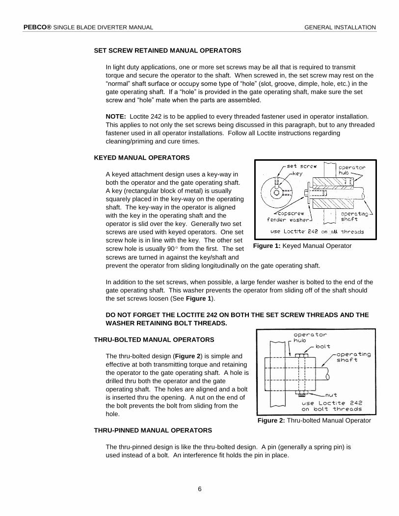
KEYED MANUAL OPERATORS
A keyed attachment design uses a key-way in
both the operator and the gate operating shaft.
A key (rectangular block of metal) is usually
squarely placed in the key-way on the operating
shaft. The key-way in the operator is aligned
with the key in the operating shaft and the
operator is slid over the key. Generally two set
screws are used with keyed operators. One set
screw hole is in line with the key. The other set
screw hole is usually 90º from the first. The set
screws are turned in against the key/shaft and
prevent the operator from sliding longitudinally on the gate operating shaft.
In addition to the set screws, when possible, a large fender washer is bolted to the end of the
gate operating shaft. This washer prevents the operator from sliding off of the shaft should
the set screws loosen (See Figure 1).
DO NOT FORGET THE LOCTITE 242 ON BOTH THE SET SCREW THREADS AND THE
WASHER RETAINING BOLT THREADS.
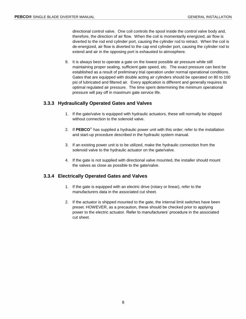
THRU-BOLTED MANUAL OPERATORS
The thru-bolted design (Figure 2) is simple and
effective at both transmitting torque and retaining
the operator to the gate operating shaft. A hole is
drilled thru both the operator and the gate
operating shaft. The holes are aligned and a bolt
is inserted thru the opening. A nut on the end of
the bolt prevents the bolt from sliding from the
hole.
THRU-PINNED MANUAL OPERATORS
The thru-pinned design is like the thru-bolted design. A pin (generally a spring pin) is
used instead of a bolt. An interference fit holds the pin in place.
Figure 2: Thru-bolted Manual Operator

PEBCO® SINGLE BLADE DIVERTER MANUAL GENERAL INSTALLATION
7
TAPERED LOCKING BUSHING MANUAL OPERATORS
Another attachment design is a locking bushing. A hub attached to the operator contains an
integral key and tapered bushing. This assembly is slipped onto the gate operating shaft.
Depending on shaft size, two or more screws are turned into the hub. The screws wedge the
bushing inward and securely lock it to the gate operating shaft.
BONDED MANUAL OPERATORS
The final design is bonding. The operator is permanently attached to the gate operating shaft
with a high strength bonding compound. When this design is used, PEBCO® specifies
LOCTITE 680.
3.3.2 Pneumatically Operated Gates and Valves
1. If the gate is equipped with pneumatic actuators, air pressure should be connected to the
directional control valves. Most pneumatic actuation systems supplied by PEBCO® are
piped at the factory and require only checking of the connections for tightness. Only one
connection is required to the directional valve. An FRL Trio should be installed in the air
pressure source line if air is not conditioned and contains moisture and contaminants. Air
pressure should not exceed 100 psig.
NOTE: A manual isolation valve should be installed just before the FRL Trio.
2. If the gate is not supplied with directional valves mounted, the installer should mount the
valves as close as possible to the gate.
3. Hook electrical power to the directional valves and limit switches.
NOTE: On totally enclosed slide gates, a conduit hole will have to be drilled in the
housing to accommodate a flexible conduit entry to the limit switches. Insure that the
conduit will not interfere with the blade movement.
4. When piping and electrical connections have been made, apply air pressure and
electrical power.
5. On directional control valves provided by PEBCO®, muffler speed controls are installed
on the exhaust port(s) of the valve. Refer to Maintenance Section 4.11.
6. Cylinder cushions are adjusted at the factory, but a check should be made before
operation. Refer to Maintenance Section 4.7.
7. During final checkout of the system, the muffler speed control(s) should be adjusted. To
adjust the muffler speed control, loosen the retainer nut on the adjustment screw. Turn
the adjustment screw all the way in until it seats and then back it out approximately 3
turns. Select either open or closed. When the cylinder starts to operate, adjust the
adjustment screw until the desired speed is obtained. Tighten the retainer nut. On some
systems, this procedure may have to be repeated for both the open and closed function.
8. Standard air cylinder cycling calls for either full open or full closed operation. This,
normally, is accomplished through the use of a 4-way, 2-position, single solenoid
PEBCO® SINGLE BLADE DIVERTER MANUAL GENERAL INSTALLATION
8
directional control valve. One coil controls the spool inside the control valve body and,
therefore, the direction of air flow. When the coil is momentarily energized, air flow is
diverted to the rod end cylinder port, causing the cylinder rod to retract. When the coil is
de-energized, air flow is diverted to the cap end cylinder port, causing the cylinder rod to
extend and air in the opposing port is exhausted to atmosphere.
9. It is always best to operate a gate on the lowest possible air pressure while still
maintaining proper sealing, sufficient gate speed, etc. The exact pressure can best be
established as a result of preliminary trial operation under normal operational conditions.
Gates that are equipped with double acting air cylinders should be operated on 80 to 100
psi of lubricated and filtered air. Every application is different and generally requires its
optimal regulated air pressure. The time spent determining the minimum operational
pressure will pay off in maximum gate service life.
3.3.3 Hydraulically Operated Gates and Valves
1. If the gate/valve is equipped with hydraulic actuators, these will normally be shipped
without connection to the solenoid valve.
2. If PEBCO® has supplied a hydraulic power unit with this order; refer to the installation
and start-up procedure described in the hydraulic system manual.
3. If an existing power unit is to be utilized, make the hydraulic connection from the
solenoid valve to the hydraulic actuator on the gate/valve.
4. If the gate is not supplied with directional valve mounted, the installer should mount
the valves as close as possible to the gate/valve.
3.3.4 Electrically Operated Gates and Valves
1. If the gate is equipped with an electric drive (rotary or linear), refer to the
manufacturers data in the associated cut sheet.
2. If the actuator is shipped mounted to the gate, the internal limit switches have been
preset. HOWEVER, as a precaution, these should be checked prior to applying
power to the electric actuator. Refer to manufacturers’ procedure in the associated
cut sheet.

PEBCO® SINGLE BLADE DIVERTER MANUAL MAINTENANCE RECOMMENDATIONS
9
4 MAINTENANCE RECOMMENDATIONS
4.1 MAINTENANCE PROGRAM IMPORTANCE
An inspection and maintenance program should be established to ensure the successful operation of
the equipment during its working life.
One of the most important aspects of any maintenance program lies in establishing a good set of
operating records. Daily log sheets should be set up to record all important operating parameters of
the equipment. Inspection at predetermined intervals is essential. The frequency of inspections may
vary with operating conditions and the environment of operation. Complete records will also indicate
spare parts used and on-hand, and the historical details of any maintenance or overhaul which takes
place.
The purpose of a good maintenance program is to achieve maximum operating performance while
holding down maintenance costs.
4.2 WEAR PARTS
Parts exposed to high frictional forces, whether due to the sliding of two parts against each other, or
due to exposure to the product flow, are expected to wear and may need to be replaced. PEBCO®
does not consider the wearing of Seals, Retainers, Liners, or Blades due to friction to be a defect as
covered under the product warranty, and replacement of said parts is considered to be the
responsibility of the purchaser.
4.3 MAINTENANCE SCHEDULE
Scheduled inspection of equipment and active preventive maintenance are essential for optimum
performance and long equipment life. This section lists suggested schedules for maintenance.
However, actual service conditions and environment greatly affect equipment reliability and such
schedules should be adjusted as necessary to suit the specific requirements of the installation

PEBCO® SINGLE BLADE DIVERTER MANUAL MAINTENANCE RECOMMENDATIONS
10
4.3.1 Suggested Maintenance Schedule
Weekly Monthly Quarterly Yearly
All S
yste
ms
Check for Dust
Leakage □
Check for
Frayed/
Exposed Wiring □
Lubricate Flange
Bearings □ Inspect
Mounting Bolts □
Pne
um
atic
Syste
ms
Check System
Pressure □ Clean/Replace
FRL Trio Filter □ Check/Clean
Muffler □ Check Air
Circuitry for
Leakage □
Drain Air Receiver
(Manual Units
Only) □
Check Drain
(Automatic Units
Only) □
Check Lubricator □ Check Cylinder
Clevis Pins □
Hydra
ulic
Syste
ms
Check System
Pressure □ Check Cylinder
Clevis Pins □ Tool Check
for Loose
Hardware □
Visually Check for
Loose Hardware □
4.3.2 Spare Part Installation Log
Date Part Qty. Comments

PEBCO® SINGLE BLADE DIVERTER MANUAL MAINTENANCE RECOMMENDATIONS
11
4.4 SAFETY PRECAUTIONS
Basic common sense and extraordinary safety precautions should be followed at all times.
!!! WARNING !!!
It is important to remember that the installation of a pneumatically or hydraulically operated gate
should be done with the air and/or fluid lines completely shut off to the directional valve operating the
gate. Should the installation or inspection work during installation be carried out on an open gate,
and an electrical power failure occurs, the gate blade will automatically go to its closed position.
It is imperative to remember that AUTOMATIC CLOSING will occur and that the directional valve(s)
must be isolated. It is also important to remember that any air and/or fluid trapped between the
directional valve(s) and the cylinder(s) should be released to atmosphere or returned to tank
whichever the case may be.
IT IS RECOMMENDED THAT A MANUAL ISOLATION VALVE BE INSTALLED IN THE SUPPLY AIR
OR HYDRAULIC LINE IMMEDIATELY BEFORE THE GATE, FOR MAINTENANCE PURPOSES.
4.5 LUBRICATION
General recommendation is for lubrication every 100 hours of operation using NLGI #2 Lithium based
grease
4.5.1 Flange Bearings
The lubrication of flange bearings is necessary only if the bearing has a grease fitting installed.
Most bearings utilized are bushing type of a bronze material, and require only light oiling. Upon
installation of the gate/valve, lubrication is not necessary. All lubrication points are lubricated at
the factory.
4.5.2 Gear Boxes
Refer to manufacturer’s recommendations listed on specific component data sheet(s) for gear
boxes (reducers, etc.).
4.5.3 Rod End Bearings
If the rod end has zerk grease it should be serviced at this time.
4.6 FRL TRIO INSPECTION/MAINTENANCE
1. Air pressure to the pneumatic circuit, 80 to 100 psi should be the normal operating range. Adjust
the pressure regulator if necessary.
2. C lean or replace the filter element every month, or when abnormal contaminant buildup is
evident. Refer to the manufacturer’s data in the associated cut sheet for filter removal.
3. Check the lubricator daily to insure that lubrication is always present to the pneumatic parts.
PEBCO® SINGLE BLADE DIVERTER MANUAL MAINTENANCE RECOMMENDATIONS
12
4. Drain the air receiver of water daily. If automatic drain is used, disregard this step.
5. Check air circuitry for leakage annually.
6. Filter, regulator and lubricator (FRL Trio) maintenance is as follows: The filter assembly will have
either an automatic or manual drain. If the filter is equipped with an automatic drain, the filter will
automatically purge itself of fluids and contaminants on a periodic basis. This drain should be
checked periodically because the automatic drains do fail occasionally. If the filter is equipped
with a manual drain, the drain should be purged on a regular basis. The filter also requires
changing or cleaning of the filter element. The type of filter media varies from one manufacturer
to another; most are of the serviceable type and require only cleaning and oiling. If the filter
becomes clogged, there will be a pressure reduction to the air circuit and will result in slower gate
movement.
The regulator assembly requires no maintenance other than periodic checks of the system
pressure. Air pressure should range from 80 to 100 psig.
The lubricator is used to inject lubricating oil into the air line. The injection of lubrication occurs
only during the time when air is drawn into the cylinders. This lubrication is used to insure free
operation of directional valves and cylinders. This assembly should be checked frequently in
heavy use to insure that lubrication is present at all times to the air circuit. Removal of the
lubricator bowl is usually necessary to refill the assembly. It is suggested that for cold weather
operation (below freezing), the additive KILL-FROST be used in the lubricator in place of the
regular lubrication petroleum based fluid. This particular product will prevent freeze-ups of the
valve and cylinder as well as providing the necessary lubrication to the components.
KILL-FROST can be used year round; however, the expense is usually prohibitive.
4.7 CYLINDER CUSHION ADJUSTMENT
Most hydraulic and some pneumatic cylinders supplied with PEBCO® gates have cushions in each
cylinder head. The cushion adjustment is by means of an allen head set screw. Turning this set
screw in increases the cushion effect at the end of travel of the cylinder. Turning this set screw out
reduces the cushion effect. The optimum setting is made at the factory by adjusting the set screw to
be flush with the face of the cylinder head, and this setting should not have to be adjusted except in
cases of disassembly for maintenance.
4.8 SEAL REPLACEMENT
Replacement of dust seals should be performed when signs of abnormal leakage and dust
concentrations are evident. In some cases, replacement seals are furnished from the factory as
blank sections of seal material slightly larger than the item they are to replace. This is necessary so
that field fit up can be made to provide the optimum seal arrangement. In most cases, however,
replacement seals are provided precut and ready for installation.
!!! WARNING !!!
The appropriate Lock-Out Tag-Out procedure should be followed before performing any maintenance
on the unit to ensure that the gate is isolated from all electrical, hydraulic, and pneumatic systems.
Likewise, all necessary steps should be taken to prevent any material from entering the gate during
maintenance or inspection.
PEBCO® SINGLE BLADE DIVERTER MANUAL MAINTENANCE RECOMMENDATIONS
13
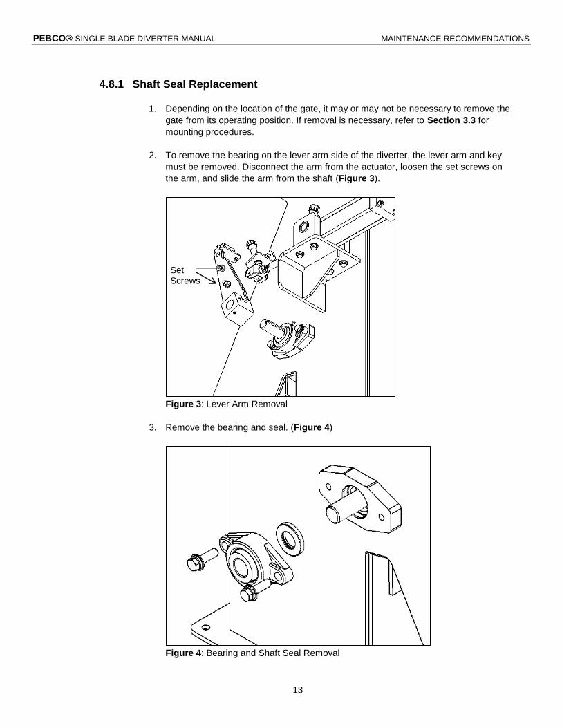
4.8.1 Shaft Seal Replacement
1. Depending on the location of the gate, it may or may not be necessary to remove the
gate from its operating position. If removal is necessary, refer to Section 3.3 for
mounting procedures.
2. To remove the bearing on the lever arm side of the diverter, the lever arm and key
must be removed. Disconnect the arm from the actuator, loosen the set screws on
the arm, and slide the arm from the shaft (Figure 3).
Figure 3: Lever Arm Removal
3. Remove the bearing and seal. (Figure 4)
Figure 4: Bearing and Shaft Seal Removal
Set Screws

PEBCO® SINGLE BLADE DIVERTER MANUAL MAINTENANCE RECOMMENDATIONS
14
4. Replace the seal and reinstall the bearing.
5. Replace the lever arm, and reapply Loctite 262 (567 for stainless steel applications)
to the set screws.
4.8.2 Blade Seal Replacement
1. Remove the diverter from service to allow access to all sides. (Refer to Section 3.3)
for mounting procedures.)
2. Disconnect the actuator from the lever arm (Figure 5) to allow manual movement of
the blade. (This step is not required for manually operated diverters.)
Figure 5: Actuator Disconnection
3. Remove the socket head cap screws that hold the seal retainers in place. (Figure 6)
4. Remove the seal retainers noting their positions and orientations and set them aside.
5. Remove the old seal material.

PEBCO® SINGLE BLADE DIVERTER MANUAL MAINTENANCE RECOMMENDATIONS
15
Figure 6: Retainer and Seal Removal
6. If the new seal did not come with bolting holes already cut, use the old seal to
transfer the locations of these holes.
7. Install the new seal and wrap tightly around the end of the blade.
8. Replace the seal retainers with existing bolting and reapply Loctite 242 or 243 (567
for stainless steel applications).
9. Pull firmly on the loose ends of the seal near the shaft.
10. Tighten the seal retainer bolts.
11. Manually cycle the gate 2-3 times and watch seal performance, especially near the
blade tip, to ensure firm contact without the seal material folding over itself.
12. Due to the nature of the seal material it will often be necessary to trim some material
near the tip of the blade as it tends to expand when wrapped around the blade tip
radius. EXTREME care should be taken not to trim too much material in this
step.
13. Reinstall the actuator and place the gate back into service.
4.9 BLADE REPLACEMENT
1. Upon receipt of the new blade be sure to review the receiving inspection covered in Section
3.1
2. Remove the diverter from service to allow access to all sides. (Refer to Section 3.3 for
mounting procedures.)
Seal
Retainer

PEBCO® SINGLE BLADE DIVERTER MANUAL MAINTENANCE RECOMMENDATIONS
16
3. Disconnect the actuator from the lever arm (Figure 5 on page 14) to allow manual movement
of the blade.
4. Remove the blade seal. Refer to Section 4.8.2, steps 3-5 (page 14).
5. Sand away any corrosion or particulate buildup from the shaft, as buildup may prevent lever
arm removal.
6. Remove the lever arm, bearings, and shaft seals. Refer to Section 4.8.1, steps 2 and 3
(page 13)
7. Remove the shaft (Figure 7). Be sure to support the blade so that it does not fall when free of
the shaft.
Figure 7: Shaft Removal
8. The blade can now be removed from the unit.
9. Position the new blade inside the unit, and reinstall the shaft. The shaft seals should be
inspected at this time and replaced if necessary.
10. Take care to insure that the shaft is re-installed with the keyway in the same orientation.
11. Install the bearings, lubricating if necessary.
12. Replace the blade seal. (Refer to Section 4.8.2, steps 6-12)
13. Replace the lever arm and actuator; remember to reapply Loctite 262 (567 for stainless steel
applications) to the set screws.
14. Mount the unit in its operating position. (Refer to Section 3.3.)

PEBCO® SINGLE BLADE DIVERTER MANUAL MAINTENANCE RECOMMENDATIONS
17
4.10 MOUNTING BOLT INSPECTION
Check gate/valve mounting bolts. Replace and/or tighten any loose or missing bolts. Use the same
quality of bolts used in installation. This should be done annually.
4.11 MUFFLER SPEED CONTROLS
Check and adjust muffler speed control when the cylinder operates slowly or if the muffler shows
excessive contamination. Maintenance of the muffler speed control should only be necessary when
the muffler becomes restricted. This will be evident due to a slowing of the gate speed.
As a preventive measure, the speed control should be checked
every three months and cleaned if necessary.
Cleaning can be done with a bath of cleaning solvent. Submerge
the muffler in the solvent. After the muffler has soaked for a few
minutes, remove it from the solution and blow off the solvent and
any residual contaminants.
To adjust the muffler speed control, loosen the retainer nut on the
adjustment screw (Figure 8). Turn the adjustment screw all the
way in until it seats and then back it out approximately 3 turns.
Select either open or closed. When the cylinder starts to operate,
adjust the adjustment screw until the desired speed is obtained.
Tighten the retainer nut. On some systems, this procedure may
have to be repeated for both the open and closed function.
4.12 TROUBLESHOOTING PNEUMATIC ACTUATORS
Pneumatic cylinder operates slowly
Check air supply pressure-should be 80 to 100 psi
Muffler speed control restricted, or dirty
Excessive cylinder leakage
Tubing to cylinder
Cushions improperly adjusted
Pneumatic cylinder will not operate
Air pressure turned off
Solenoid coil open
Muffler speed control restricted
Directional valve spool seized in valve body
No electrical power to the directional valve coil circuit
Gross air leakage
Figure 8: Muffler Retainer Nut (a) and Adjustment Screw (b).
(a)
(b)

PEBCO® SINGLE BLADE DIVERTER MANUAL MAINTENANCE RECOMMENDATIONS
18
Pneumatic cylinder drifts
Internal cylinder leakage
Directional valve spool worn
Loose connection to cylinder ports
Water comes from directional valve exhaust port
Air source too wet, dew point too low
Auto drain not functioning
Drain filter regulator
Replace air dryer desiccant
Directional valve will not operate when coil is energized
Coil open
Valve spool seized
Internal valve leakage
4.13 HYDRAULIC SYSTEMS
Refer to manufacturer’s data sheets on items furnished on this order.
If Hydraulic Power Unit is supplied on this order by PEBCO®, refer to the Hydraulic System Manual
for detailed operation.

PEBCO® SINGLE BLADE DIVERTER MANUAL WARRANTY
19
5 WARRANTY
WARRANTY: PEBCO® SINGLE BLADE DIVERTER
WARRANTY
PEBCO® warrants to purchaser, upon the terms set forth, that the equipment purchased, so far
as the same is of PEBCO®’s manufacture, is free from defects in material and workmanship
under normal use and service for a period of twelve (12) months from the date of shipment.
All equipment, including motors, manufactured by others, is warranted solely and exclusively by
their manufacturers and not by PEBCO®, and PEBCO® hereby assigns to purchaser without
recourse to PEBCO® such warranty as is given by the manufacturer.
TERMS
PEBCO®’s obligation under this warranty is limited to and shall be fully discharged by
PEBCO® repairing or at its option replacing f.o.b. point of manufacturer any part which is shown
to PEBCO®’s satisfaction to have been defective as to material or workmanship, provided that
written notice of defect is delivered to PEBCO®’s office in Paducah, Kentucky, within sixty (60)
days after defect is discovered, and in no event more than twelve (12) months and sixty (60) days
after shipment.
PURCHASER’S ACTS VOIDING WARRANTY
The warranty furnished by PEBCO® herein will be rendered void by improper erection or
installation, if executed by other than PEBCO®, misuse, unauthorized alteration, substitutions,
repairs or modifications, neglect or accident, or damage to the equipment caused by improper
storage, abrasion, corrosion, and/or operation outside the rated load limitations for use of the
equipment. PEBCO® shall not be liable for any repairs, replacements or adjustments to the
equipment or any cost of labor performed by the purchaser or others without PEBCO®’s prior
written approval.
EXCLUSION OF ALL OTHER WARRANTIES AND LIMITATION OF CONSEQUENTIAL AND
INCIDENTAL DAMAGES.
1. THE W A R R A N T Y F U R N I S H E D B Y P E B C O ® AS E X P R E S S L Y
I N C L U D E D HEREIN IS IN LIEU OF ANY OTHER WARRANTIES OR GUARANTIES
EXPRESSED OR IMPLIED. PEBCO® MAKES NO OTHER WARRANTY OR
REPRESENTATION OF ANY KIND WHATSOEVER, EXPRESSED OR IMPLIED,
EXCEPT THAT OF TITLE AND ALL IMPLIED WARRANTIES INCLUDING ANY
WARRANTY OF DESIGN, MERCHANTABILITY AND FITNESS FOR A PARTICULAR
PURPOSE ARE HEREBY DISCLAIMED.
2. IN NO EVENT, BE IT DUE TO A BREACH OF WARRANTY OR ANY OTHER CAUSE
ARISING OUT OF PERFORMANCE OR NONPERFORMANCE OF THIS PROPOSAL
OR CONTRACT, SHALL PEBCO® BE LIABLE FOR (1) CONSEQUENTIAL OR
INDIRECT LOSS OR DAMAGE INCLUDING BUT NOT LIMITED TO LOSS OF
PROFITS, COSTS TO PURCHASE SUBSTITUTE POWER, PLANT DOWNTIME,
PRODUCTION, INCREASED COSTS OF OPERATION, OR SPOILAGE OF MATERIAL,
OR (2) LOSS OR DAMAGE ARISING OUT OF THE NEGLIGENCE OF THE
PURCHASER, ITS EMPLOYEES, AGENTS, ENGINEERS OR ARCHITECT.

PEBCO® SINGLE BLADE DIVERTER MANUAL COMPONENTS
20
6 COMPONENTS
Component list and manuals available separately, please see “Components Manuals” on our website
www.pebco.com.

PEBCO® SINGLE BLADE DIVERTER MANUAL
21
This page intentionally left blank