single-, dual- and triple-band frequency reconfigurable antenna · · 2014-08-25radioengineering,...
TRANSCRIPT
RADIOENGINEERING, VOL. 23, NO. 3, SEPTEMBER 2014 805
Single-, Dual- and Triple-band Frequency Reconfigurable Antenna
Izni Husna IDRIS1, Mohamad Rijal HAMID1, Mohd Haizal JAMALUDDIN2, Mohamad Kamal A. RAHIM1, James R. KELLY3, Huda A. MAJID1
1 UTM-MIMOS Center, Fakulti Kejuruteraan Elektrik, Universiti Teknologi Malaysia, Skudai, Johor, Malaysia 2 Wireless Communication Center, Fakulti Kejuruteraan Elektrik, Universiti Teknologi Malaysia, Skudai, Johor, Malaysia
3 Centre for Communication Systems Research, Faculty of Engineering and Physical Sciences, University of Surrey, Guildford, GU2 7XH, United Kingdom
[email protected], [email protected], [email protected], [email protected], [email protected], [email protected]
Abstract. The paper presents a frequency reconfigurable slot dipole antenna. The antenna is capable of being switched between single-band, dual-band or triple-band operation. The antenna incorporates three pairs of pin-diodes which are located within the dipole arms. The antenna was designed to operate at 2.4 GHz, 3.5 GHz and 5.2 GHz using the aid of CST Microwave Studio. The aver-age measured gains are 1.54, 2.92 and 1.89 dBi for low, mid and high band respectively. A prototype was then constructed in order to verify the performance of the de-vice. A good level of agreement was observed between simulation and measurement.
Keywords Frequency reconfigurable antenna, slot antenna.
1. Introduction The demands on communications systems have in-
creased dramatically in recent years. Modern communica-tions systems often incorporate numerous radio transceiv-ers each operating at a different frequency. It is no longer practical to provide a dedicated antenna element for each individual radio. Fortunately a frequency reconfigurable antenna, based on using a single radiating element is able to cover a variety of different frequencies and beam-width as reported in [1], [2]. In comparison with fixed multiband antennas, reconfigurable antennas increase the flexibility of a radio system [3]. Some fixed multi-band antennas are reported in [4]-[6]. In terms of gain, the performance of the fixed multi-band antennas is better than that of their recon-figurable counterparts. This can be attributed to losses within the switches of a reconfigurable antenna. However fixed multiband antennas can only operate at certain fre-quencies as compared to reconfigurable antenna that can access a range of operating frequencies. This is important for cognitive radio and spectrum aggregation both of which
will require antennas that can reconfigure their operating parameters. A fixed multiband antenna would not be ade-quate for use in these applications. Reconfigurable antenna is achieved through the use of microwave switches, such as MEMS or pin-diodes. The latter being the more popular choice. The reason for this is that MEMS switches are more expensive, afford lower reliability and require a higher bias voltage compared to pin-diodes [7]. Pin diodes, on the other hand, are based on more mature tech-nology and are thus more readily available.
Broadly speaking the techniques for frequency recon-figuration can be divided into three main classes: 1) nar-rowband to another narrowband [8], 2) wideband to narrowband [9], and 3) multi-band to another multi-band [10]-[13]. An antenna that can be reconfigured from one narrowband to another narrowband is only capable of sup-porting one radio standard at a time. An antenna that can be reconfigured from wideband to narrowband, on the other hand, can support multiple radio standards at a time. However, the wideband operation inherently provides less interference rejection than narrowband operation. This limitation, is addressed by employing an antenna that can be reconfigured from one multi-band to another multi-band is preferred [10]-[13]. In [10], a varactor diode is used to tune the frequency location of the multi-band. In this way the antenna is able to cover a wide range of different fre-quencies. In [11], RF MEMS switches are used to achieve multiband reconfiguration in four different states. The antenna exhibits two dual-band states and two triple-band states. In this way the antenna is able to cover a wide fre-quency range from 0.8 GHz to 6 GHz. The antennas pro-posed in [12]-[13] can switch between single-band, dual-band, or multi-band operation.
The sickle-shaped slot antenna, reported in [12], in-corporates six pin-diode switches. These switches are used to activate or deactivate certain slots. Consequently the antenna is able to provide seven different operating modes. The antenna proposed in [13] incorporates two switches. These switches enable it to provide three different operat-
806 I. H. IDRIS, M. R. HAMID, M. H. JAMALUDDIN, M. K. A. RAHIM, J. R. KELLY, H. A. MAJID, SINGLE-, DUAL- AND TRIPLE-BAND…
ing states, namely: 2 dual-band and 1 triple-band mode. The antenna has applications in Bluetooth, WiMAX, and WLAN systems.
This paper proposes a new design for a frequency reconfigurable multi-band antenna based around a slot di-pole. Three pairs of pin-diode switches are placed across, the dipole arms. It is possible to reconfigure the operating frequency of the antenna, by altering the states of the switches. In total, the proposed antenna is capable of oper-ating in seven different states: three single-band, three dual-band, and one triple-band. The reminder of the paper is organized as follows: Section 2 describes the geometry of the antenna. Section 3 presents the simulation and meas-urement results. Finally Section 4 presents the conclusions.
2. Antenna Design Fig. 1 describes the structure of the antenna along
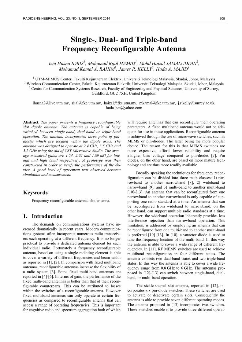
with the DC-bias circuitry used to control the microwave switches. The antenna is based on a design presented in [14] and consists of three pairs of slots, positioned in se-ries. Then, the slots are merged into a rectangular box to have a stable and better impedance matching results. These slots are etched into the ground plane. The antenna is fed via a CPW transmission line.
It is fabricated on an FR-4 substrate having a relative permittivity (εr) of 4.3 and a thickness (h) of 1.6 mm. The size of the substrate is 83.1 mm × 47 mm. This size is cho-sen because it gives better S11 result after optimization was done. It is worth to note that the height of the substrate has a strong effect on the lowest resonance frequency. The geometrical parameters of the proposed antenna are given in Tab. 1. In comparison with a fixed multiband antenna, the proposed antenna can be reconfigured between a larger numbers of operating bands. The antenna also provides a degree of additional filtering, which would have the effect of reducing the level of interference at the receiver.
These factors represent significant advantages in compari-son with [14].
Each dipole arms is approximately half-a-wavelength long at the corresponding resonant frequency. For example, the uppermost arm has a length of 62.1 mm which is approximately half-a-wavelength long at 2.45 GHz. The middle and lower arms are 46.6 mm and 36.7 mm long, respectively. To obtain the best results, the values of all of the geometrical parameters have been optimized using a computer simulation tool. This is necessary to account for the specific path taken by the surface currents as well as the effect of fringing fields. Three pairs of pin-diode switches are inserted into the antenna, as mentioned earlier. An Infineon BAR50-02V pin-diode was employed in the prototype antenna [15]. Fig. 2 shows the equivalent circuit for pin-diode in the on-state. Fig. 3 and Fig. 4 show the equivalent circuit for pin-diode in the off-state. At frequen-cies below 4 GHz the value of capacitor is 0.15 pF. At frequencies above 4 GHz the capacitor value is 0.12 pF. The pin-diode pairs are denoted D1, D2 and D3. These pairs of diodes are located on the upper, middle, and lower pairs of dipole arms, respectively. The electromagnetic computer simulations results reported in this paper were obtained using CST Microwave Studio® 2012 [16].
Parameters Dimensions (mm)
Parameters Dimensions (mm)
g 0.50 n 5.00 k 19.00 w 3.00 l1 16.55 w1 0.50 l2 8.80 w2 0.50 l3 3.85 w3 1.00 m 13.00
Tab. 1. Parameter value of the antenna design.
Fig. 2. Pin-diode on state equivalent circuit.
Substrate: FR-4, h=1.6 mm, εr=4.3
D1
D2
D3
k
n
g
62.1 mm
inductor
shorting capacitor
0.3 mm slit
g
l3
l2
l1 m ww1
w2
w3
y
x
83.1 mm
47 mm
Fig. 1. The geometry of the proposed antenna.
RADIOENGINEERING, VOL. 23, NO. 3, SEPTEMBER 2014 807
Fig. 3. Pin-diode off state equivalent circuit, frequency
< 4 GHz.
Fig. 4. Pin-diode off state equivalent circuit, frequency
≥ 4 GHz.
Tab. 2 describes the switch states required in order to obtain each of the seven different operating bands. States one, two, and three yield single-band operation. They are achieved by switching off only one pair of pin-diodes. The remaining pairs of diodes are switched on. To be specific, state one is achieved by switching off diode pair D1. State two, on the other hand, is achieved by switching off diode pair D2. In contrast, states four, five, and six are obtained by switching on only one pair of diodes. These states yield dual-band operation. To be specific, state five is achieved when only diode pair D2 is switch on. Finally, if all of the pin-diodes are turned off, triple-band operation is achieved. This is referred to as state seven.
State D1 D2 D3 Bands 1 off on on Single-band : (low) 2 on off on Single-band : (mid) 3 on on off Single-band : (high) 4 off off on Dual-band : (low & mid) 5 off on off Dual-band : (low & high) 6 on off off Dual-band : (mid & high) 7 off off off Triple-band : (low, mid & high)
Tab. 2. Switch configuration of the antenna design.
In the prototype, the biasing circuit comprises a num-ber of 100 pF capacitor along with a 27 nH inductors. Each of the capacitors behaves as a DC block while each of the inductors serves as an RF choke. A series of 0.3 mm slits are introduced into the ground plane, as shown in the inset of Fig. 1. These slits serve as a means of isolating the bias voltages applied to the different switches from one another.
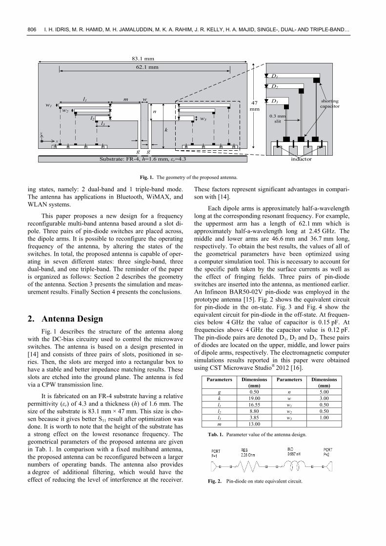
3. Results and Discussions Fig. 5 shows a photograph of the fabricated antenna.
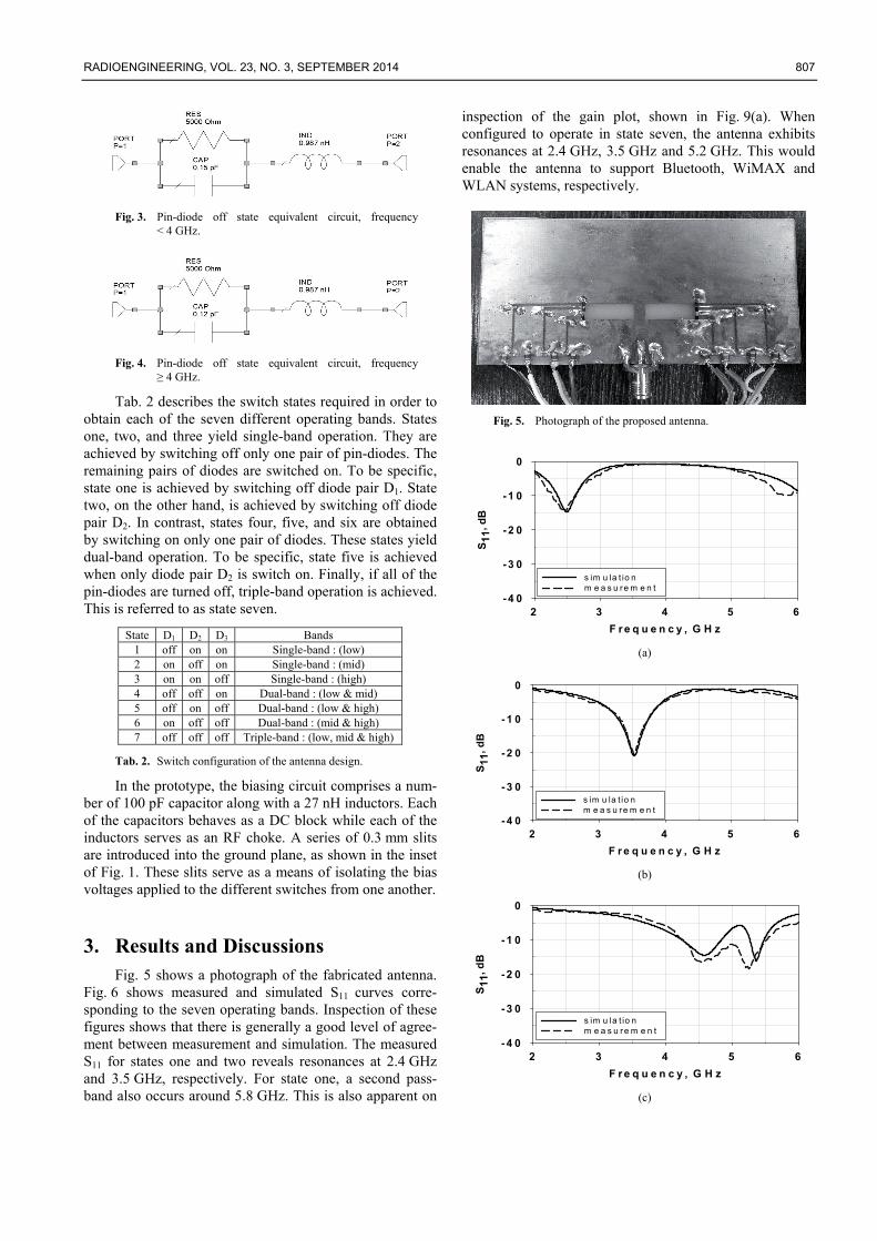
Fig. 6 shows measured and simulated S11 curves corre-sponding to the seven operating bands. Inspection of these figures shows that there is generally a good level of agree-ment between measurement and simulation. The measured S11 for states one and two reveals resonances at 2.4 GHz and 3.5 GHz, respectively. For state one, a second pass-band also occurs around 5.8 GHz. This is also apparent on
inspection of the gain plot, shown in Fig. 9(a). When configured to operate in state seven, the antenna exhibits resonances at 2.4 GHz, 3.5 GHz and 5.2 GHz. This would enable the antenna to support Bluetooth, WiMAX and WLAN systems, respectively.
Fig. 5. Photograph of the proposed antenna.
F r e q u e n c y , G H z
2 3 4 5 6
S1
1, d
B
- 4 0
-3 0
-2 0
-1 0
0
s im u la t io n m e a s u re m e n t
(a)
F r e q u e n c y , G H z
2 3 4 5 6
S1
1,
dB
- 4 0
- 3 0
- 2 0
- 1 0
0
s im u la t io n m e a s u re m e n t
(b)
F r e q u e n c y , G H z
2 3 4 5 6
S1
1, d
B
- 4 0
-3 0
-2 0
-1 0
0
s im u la t io n m e a s u re m e n t
(c)
808 I. H. IDRIS, M. R. HAMID, M. H. JAMALUDDIN, M. K. A. RAHIM, J. R. KELLY, H. A. MAJID, SINGLE-, DUAL- AND TRIPLE-BAND…
F r e q u e n c y , G H z
2 3 4 5 6
S11
, dB
- 4 0
-3 0
-2 0
-1 0
0
s im u la t io n m e a s u re m e n t
(d)
F r e q u e n c y , G H z
2 3 4 5 6
S11
, dB
- 4 0
-3 0
-2 0
-1 0
0
s im u la t io n m e a s u re m e n t
(e)
F re q u e n c y , G H z
2 3 4 5 6
S11
, dB
- 4 0
-3 0
-2 0
-1 0
0
s im u la t io n m e a s u re m e n t
(f)
F re q u e n c y , G H z
2 3 4 5 6
S11
, dB
- 4 0
-3 0
-2 0
-1 0
0
s im u la t io n m e a s u re m e n t
(g)
Fig. 6. Measured and simulated S11 of the antenna: (a) state one, (b) state two, (c) state three, (d) state four, (e) state five, (f) state six, (g) state seven.
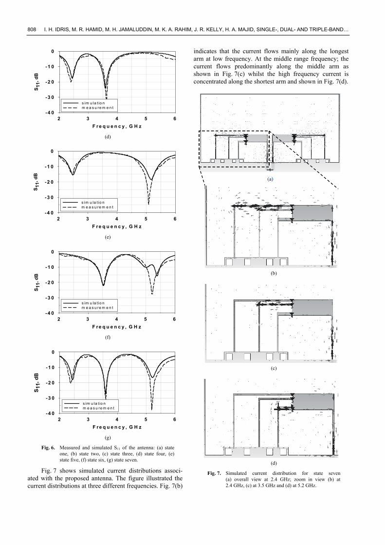
Fig. 7 shows simulated current distributions associ-ated with the proposed antenna. The figure illustrated the current distributions at three different frequencies. Fig. 7(b)
indicates that the current flows mainly along the longest arm at low frequency. At the middle range frequency; the current flows predominantly along the middle arm as shown in Fig. 7(c) whilst the high frequency current is concentrated along the shortest arm and shown in Fig. 7(d).
(b)
(c)
(d)
Fig. 7. Simulated current distribution for state seven (a) overall view at 2.4 GHz; zoom in view (b) at 2.4 GHz, (c) at 3.5 GHz and (d) at 5.2 GHz.
RADIOENGINEERING, VOL. 23, NO. 3, SEPTEMBER 2014 809
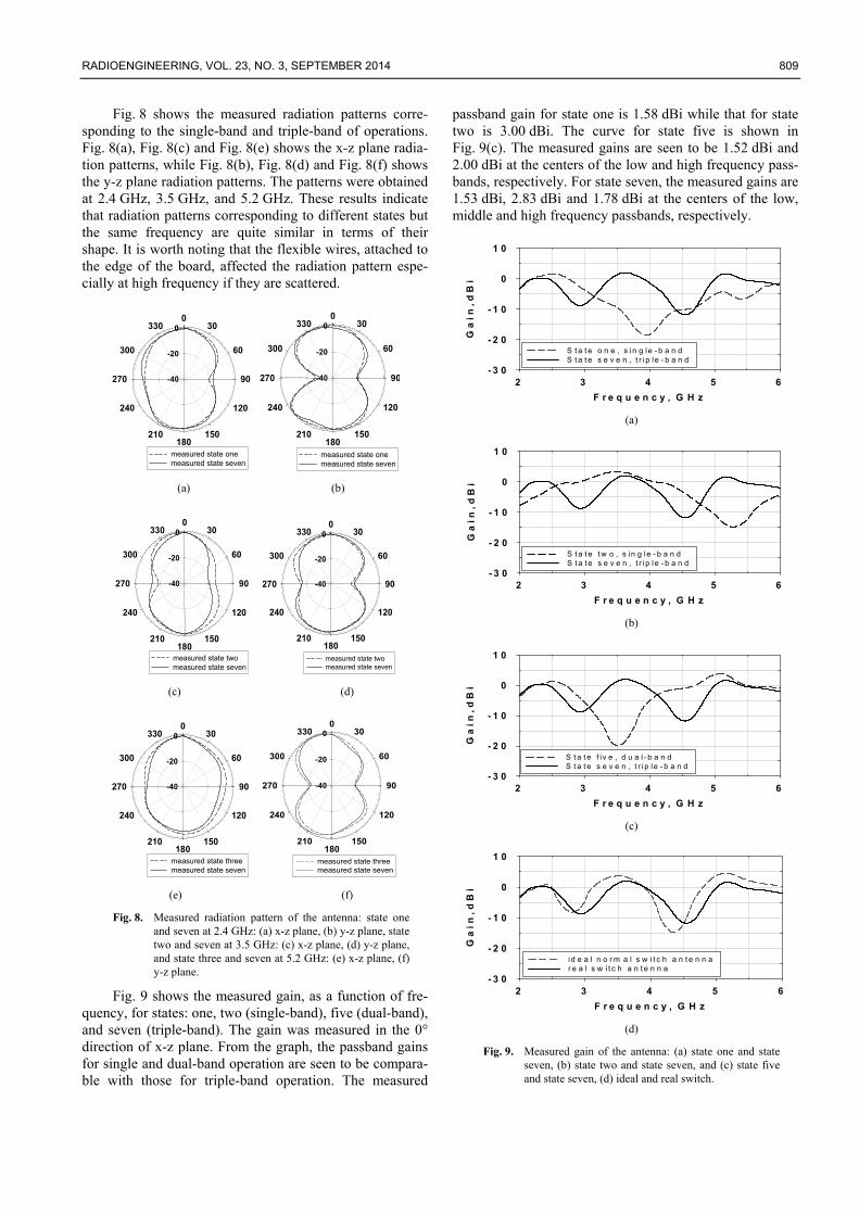
Fig. 8 shows the measured radiation patterns corre-sponding to the single-band and triple-band of operations. Fig. 8(a), Fig. 8(c) and Fig. 8(e) shows the x-z plane radia-tion patterns, while Fig. 8(b), Fig. 8(d) and Fig. 8(f) shows the y-z plane radiation patterns. The patterns were obtained at 2.4 GHz, 3.5 GHz, and 5.2 GHz. These results indicate that radiation patterns corresponding to different states but the same frequency are quite similar in terms of their shape. It is worth noting that the flexible wires, attached to the edge of the board, affected the radiation pattern espe-cially at high frequency if they are scattered.
-40
-20
00
30
60
90
120
150180
210
240
270
300
330
measured state onemeasured state seven
-40
-20
00
30
60
90
120
150180
210
240
270
300
330
measured state onemeasured state seven
(a) (b)
-40
-20
00
30
60
90
120
150180
210
240
270
300
330
measured state twomeasured state seven
-40
-20
00
30
60
90
120
150180
210
240
270
300
330
measured state twomeasured state seven
(c) (d)
-40
-20
00
30
60
90
120
150180
210
240
270
300
330
measured state threemeasured state seven
-40
-20
00
30
60
90
120
150180
210
240
270
300
330
measured state threemeasured state seven
(e) (f)
Fig. 8. Measured radiation pattern of the antenna: state one and seven at 2.4 GHz: (a) x-z plane, (b) y-z plane, state two and seven at 3.5 GHz: (c) x-z plane, (d) y-z plane, and state three and seven at 5.2 GHz: (e) x-z plane, (f) y-z plane.
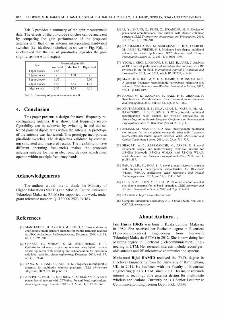
Fig. 9 shows the measured gain, as a function of fre-quency, for states: one, two (single-band), five (dual-band), and seven (triple-band). The gain was measured in the 0° direction of x-z plane. From the graph, the passband gains for single and dual-band operation are seen to be compara-ble with those for triple-band operation. The measured
passband gain for state one is 1.58 dBi while that for state two is 3.00 dBi. The curve for state five is shown in Fig. 9(c). The measured gains are seen to be 1.52 dBi and 2.00 dBi at the centers of the low and high frequency pass-bands, respectively. For state seven, the measured gains are 1.53 dBi, 2.83 dBi and 1.78 dBi at the centers of the low, middle and high frequency passbands, respectively.
F r e q u e n c y , G H z
2 3 4 5 6
G a
i n
, d
B i
- 3 0
- 2 0
- 1 0
0
1 0
S t a t e o n e , s in g le - b a n dS t a t e s e v e n , t r i p le - b a n d
(a)
F r e q u e n c y , G H z
2 3 4 5 6
G a
i n
, d
B i
- 3 0
- 2 0
- 1 0
0
1 0
S t a t e t w o , s in g le - b a n dS t a t e s e v e n , t r ip le - b a n d
(b)
F r e q u e n c y , G H z
2 3 4 5 6
G a
i n
, d
B i
- 3 0
- 2 0
- 1 0
0
1 0
S t a t e f i v e , d u a l - b a n dS t a t e s e v e n , t r i p l e - b a n d
(c)
F r e q u e n c y , G H z
2 3 4 5 6
G a
i n
, d
B i
- 3 0
- 2 0
- 1 0
0
1 0
i d e a l n o r m a l s w i t c h a n t e n n ar e a l s w i t c h a n t e n n a
(d)
Fig. 9. Measured gain of the antenna: (a) state one and state seven, (b) state two and state seven, and (c) state five and state seven, (d) ideal and real switch.
810 I. H. IDRIS, M. R. HAMID, M. H. JAMALUDDIN, M. K. A. RAHIM, J. R. KELLY, H. A. MAJID, SINGLE-, DUAL- AND TRIPLE-BAND…
Tab. 3 provides a summary of the gain measurement data. The effects of the pin-diode switches can be analyzed by comparing the gain performance of the proposed antenna with that of an antenna incorporating hardwired switches (i.e. idealized switches) as shown in Fig. 9(d). It is observed that the use of pin-diodes degrades the gain slightly, as one would expect.
Measured gain, dBi State
Low band Mid band High band 1 (pin-diode) 1.58 - -
2 (pin-diode) - 3.00 -
5 (pin-diode) 1.52 - 2.00
7 (pin-diode) 1.53 2.83 1.78
Ideal switch 2.87 3.24 4.11
Tab. 3. Summary of gain measurement result.
4. Conclusion This paper presents a design for novel frequency re-
configurable antenna. It is shown that frequency recon-figurability can be achieved by switching in and out se-lected pairs of dipole arms within the antenna. A prototype of the antenna was fabricated. This prototype incorporates pin-diode switches. The design was validated by compar-ing simulated and measured results. The flexibility to have different operating frequencies makes the proposed antenna suitable for use in electronic devices which must operate within multiple frequency bands.
Acknowledgements
The authors would like to thank the Ministry of Higher Education (MOHE) and MIMOS Center, Universiti Teknologi Malaysia (UTM) for supported this work, under grant reference number: Q.J130000.2523.04H83.
References
[1] MANTEUFFEL, D., ARNOLD, M., UHLIG, P. Considerations on configurable multi-standard antennas for mobile terminals realized in LTCC technology. Radioengineering, December 2009, vol. 18, no. 4, p. 395–401.
[2] CHAKER, H., MERIAH, S. M., BENDIMERAD, F. T. Optimization of micro strip array antennas using hybrid particle swarm optimizer with breeding and subpopulation for maximum side-lobe reduction. Radioengineering, December 2008, vol. 17, no. 4, p. 39–44.
[3] YANG, S., ZHANG, C., PAN, H. K. Frequency-reconfigurable antennas for multiradio wireless platforms. IEEE Microwave Magazine, 2009, vol. 10, p. 66–83.
[4] JOSEPH, S., PAUL, B., MRIDULA, S., MOHANAN, P. A novel planar fractal antenna with CPW-feed for multiband applications. Radioengineering, December 2013, vol. 22, no. 4, p. 1262–1266.
[5] LI, Y., ZHANG, Z., FENG, Z., ISKANDER, M. F. Design of penta-band omnidirectional slot antenna with slender columnar structure. IEEE Transactions on Antennas and Propagation, 2014, vol. 62, no. 2, p. 594–601.
[6] NASER-MOGHADASI, M., SADEGHZADEH, R. A., FAKHERI, M., ARIBI, T., VIRDEE, B. S. Miniature hook-shaped multiband antenna for mobile applications. IEEE Antennas and Wireless Propagation Letters, 2012, vol. 11, p. 1096–1099.
[7] YEOM, I., CHOI, J., KWOUN, S.-S., LEE, B., JUNG, C. Analysis of RF front-end performance of reconfigurable antennas with RF switches in the far field. International Journal of Antennas and Propagation, 2014, vol. 2014, article ID 385730, p. 1–14.
[8] MAJID, H. A., RAHIM, M. K. A., HAMID, M. R., ISMAIL, M. F. A compact frequency-reconfigurable narrowband microstrip slot antenna. IEEE Antennas and Wireless Propagation Letters, 2012, vol. 11, p. 616–619.
[9] HAMID, M. R., GARDNER, P., HALL, P. S., GHANEM, F. Switched-band Vivaldi antenna. IEEE Transactions on Antennas and Propagation, 2011, vol. 59, no. 5, p. 1472–1480.
[10] ABUTARBOUSH, H. F., NILAVALAN, R., NASR, K. M., AL-RAWESHIDY, H. S., BUDIMIR, D. Widely tunable multiband reconfigurable patch antenna for wireless applications. In Proceedings of the Fourth European Conference on Antennas and Propagation (EuCAP). Barcelona (Spain), 2010, p. 1–3.
[11] BEMANI, M., NIKMEHR, S. A novel reconfigurable multiband slot antenna fed by a coplanar waveguide using radio frequency microelectro-mechanical system switches. IEEE Microwave and Optical Technology Letters, 2011, vol. 53, p. 751–757.
[12] SHAGATI, A. P., AZARMANESH, M., ZAKER, R. A novel switchable single- and multifrequency triple-slot antenna for 2.4-GHz Bluetooth, 3.5-GHz WiMAX, and 5.8-GHz WLAN. IEEE Antennas and Wireless Propagation Letters, 2010, vol. 9, p. 534–537.
[13] PAN, Y., LIU, K., HOU, Z. A novel printed microstrip antenna with frequency reconfigurable characteristics for Bluetooth/ WLAN/ WiMAX applications. IEEE Microwave and Optical Technology Letters, 2013, vol. 55, p. 1341–1345.
[14] CHEN, S.-Y., CHEN, Y.-C., HSU, P. CPW-fed aperture-coupled slot dipole antenna for tri-band operation. IEEE Antennas and Wireless Propagation Letters, 2008, vol. 7, p. 535–537.
[15] BAR50-02V, http://www.infineon.com/
[16] Computer Simulation Technology (CST) Studio Suite. ver. 2013, CST AG, www.cst.com
About Authors ... Izni Husna IDRIS was born in Kuala Lumpur, Malaysia in 1989. She received her Bachelor degree in Electrical (Telecommunication) Engineering from Universiti Teknologi Malaysia (UTM) in 2012. She is now doing her Master's degree in Electrical (Telecommunication) Engi-neering in UTM. Her research interests include reconfigur-able antenna and RF microwave communication systems.
Mohamad Rijal HAMID received the Ph.D. degree in Electrical Engineering from the University of Birmingham, UK, in 2011. He has been with the Faculty of Electrical Engineering (FKE), UTM, since 2001. His major research interest is reconfigurable antenna design for multimode wireless applications. Currently he is a Senior Lecturer at Communication Engineering Dept., FKE, UTM.
RADIOENGINEERING, VOL. 23, NO. 3, SEPTEMBER 2014 811
Mohd Haizal JAMALUDDIN received the Doctoral degree in Signal Processing and Telecommunications from the University de Rennes 1, France in 2009. His research interests include antenna design for millimeter wave appli-cations, RF and microwave communication systems and specific antennas such as dielectric resonator, reflect array and dielectric dome antennas. He joined Universiti Teknologi Malaysia in 2003 as a Tutor at the Dept. of Electronic Engineering, Faculty of Electrical Engineering. Currently he is a Senior Lecturer at Wireless Communica-tion Centre, Faculty of Electrical Engineering, Universiti Teknologi Malaysia.
Mohamad Kamal A. RAHIM received his Ph.D. degrees in Electrical Engineering from University of Birmingham UK in 2003. In 2005 he was appointed as a senior lecturer and in 2007 he was appointed as Assoc Professor at the faculty. Now he is the Professor in RF and Antenna at Faculty of Electrical Engineering Universiti Teknologi Malaysia. His research interest includes the areas of design of dielectric resonator antennas, microstrip antennas, small antennas, microwave sensors, RFID antennas for readers and tags, multi-function antennas, microwave circuits, EBG, artificial magnetic conductors, metamaterials, phased
array antennas, computer aided design for antennas and design of millimeter frequency antennas. He has published over 200 articles in journals and conference papers.
James R. KELLY received the Ph.D. degree in Micro-wave Filters (2007) from Loughborough University, Leicestershire, England. Dr. James Kelly is currently a lecturer within the Centre for Communication Systems Research (CCSR) at the University of Surrey, Guildford, Surrey, England. His research interests include: body area networks, reconfigurable microwave circuits, microwave antennas, microwave filters, and metamaterials. He has published almost 60 academic papers in peer reviewed journals and conference proceedings. He frequently acts as a reviewer for various IEEE publications.
Huda A. MAJID received the Ph.D degree in Electrical Engineering from Universiti Teknologi Malaysia, in 2014. During the M.S. degree at Universiti Teknologi Malaysia, he conducted research focused on left-handed metamaterial and is currently developing frequency reconfigurable antenna for future wireless communications. His research interests concentrate mainly on reconfigurable antennas, metamaterials and textile antennas.