single-line speakerphone speakerphone 1.2 last number redial 1.3 mute 1.4 hold 1.5 flash ... the...
TRANSCRIPT
single-line
usersguide
businessspeakerphone
EUROPEAN STANDARDSTeledex phone model B120 has been successfully tested to the applicable European standards below:
TELECOMMUNICATIONS (R&TTE DIRECTIVE 99/5/EC)TBR 21 (EN 301 437)- Access to Public Switch Telecommunications Network TBR 38- Acoustics (Analog voice device with handset)
SAFETY89/336/EEC - EMC directive (EN 61000-4-2;4-3;4-4;4-5;4-6;4-8), EN 55022:1998, EN 550024, EN 61000-3-373/23/EEC - Low Voltage Directive (CB scheme covering 33 countries) EN 60950
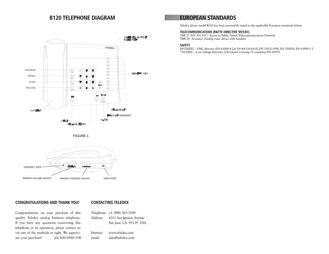
B120 TELEPHONE DIAGRAM
CONTACTING TELEDEX
Telephone: +1 (408) 363-3100
Address: 6311 San Ignacio Avenue
San Jose, CA 95119 USA
Internet: www.teledex.com
email: [email protected]
CONGRATULATIONS AND THANK YOU!
Congratulations on your purchase of this
quality Teledex analog business telephone.
If you have any questions concerning this
telephone or its operation, please contact us
via one of the methods at right. We appreci-
ate your purchase! p/n 600-0480-51B
PROGRAM
REDIAL
FLASH
RELEASE
FIGURE 1
RINGER VOLUME ADJUST
HEADSET JACK
RINGER CADENCE ADJUST DATA PORT
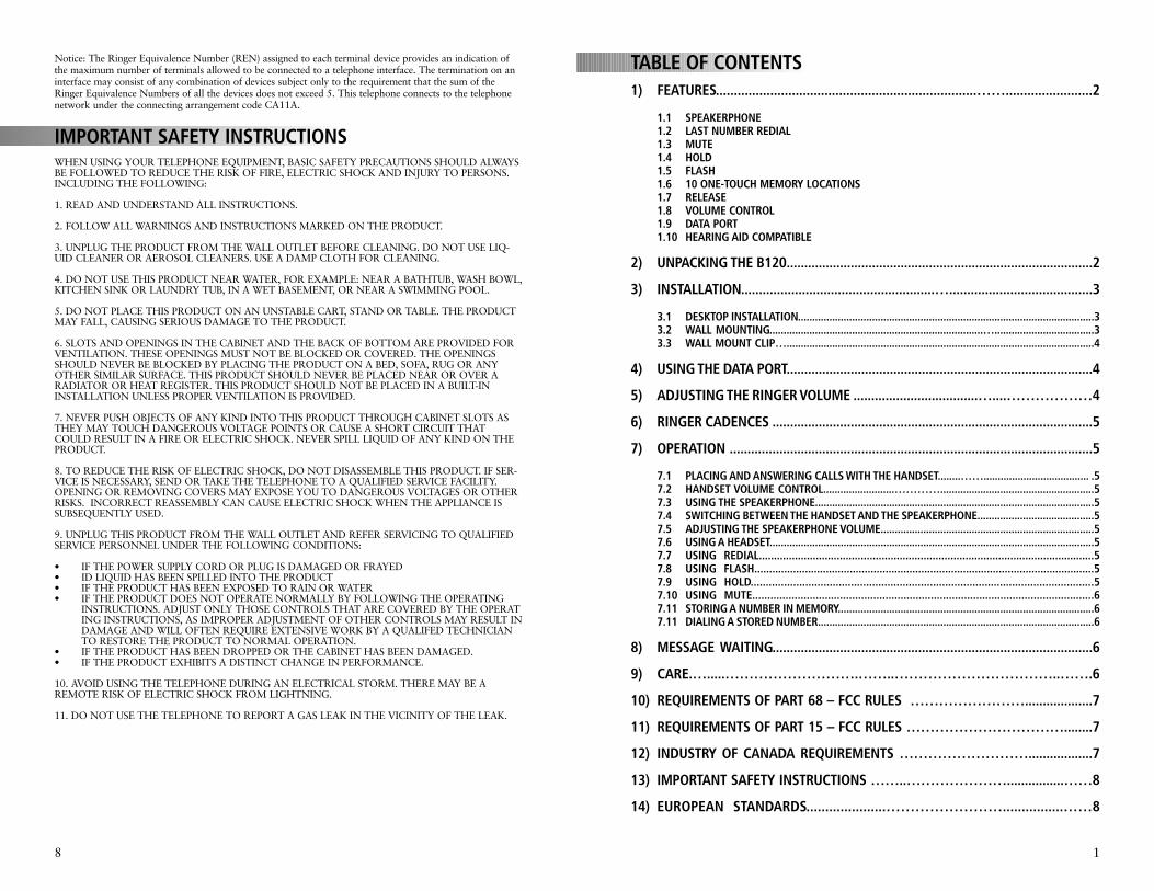
TABLE OF CONTENTS1) FEATURES........................................................................……........................2
1.1 SPEAKERPHONE1.2 LAST NUMBER REDIAL1.3 MUTE1.4 HOLD1.5 FLASH1.6 10 ONE-TOUCH MEMORY LOCATIONS1.7 RELEASE1.8 VOLUME CONTROL1.9 DATA PORT1.10 HEARING AID COMPATIBLE
2) UNPACKING THE B120......................................................................................2
3) INSTALLATION......................................................…........................................3
3.1 DESKTOP INSTALLATION........................................................................................................33.2 WALL MOUNTING...........................................................................…...................................33.3 WALL MOUNT CLIP…............................................................................................................4
4) USING THE DATA PORT......................................................................................4
5) ADJUSTING THE RINGER VOLUME ...................................…....………………4
6) RINGER CADENCES ..........................................................................................5
7) OPERATION ......................................................................................................5
7.1 PLACING AND ANSWERING CALLS WITH THE HANDSET........……..................................... .57.2 HANDSET VOLUME CONTROL.........................…………......................................................57.3 USING THE SPEAKERPHONE..................................................................................................57.4 SWITCHING BETWEEN THE HANDSET AND THE SPEAKERPHONE.........................................57.5 ADJUSTING THE SPEAKERPHONE VOLUME...........................................................................57.6 USING A HEADSET..................................................................................................................57.7 USING REDIAL................................................................................................................57.8 USING FLASH..................................................................................................................57.9 USING HOLD.................................................................................................................57.10 USING MUTE.................................................................................................................67.11 STORING A NUMBER IN MEMORY..........................................................................................67.11 DIALING A STORED NUMBER.................................................................................................6
8) MESSAGE WAITING..........................................................................................6
9) CARE.….....……………………….……..……………………………..…….6
10) REQUIREMENTS OF PART 68 – FCC RULES ……………………...................7
11) REQUIREMENTS OF PART 15 – FCC RULES ……………………………........7
12) INDUSTRY OF CANADA REQUIREMENTS ………………………..................7
13) IMPORTANT SAFETY INSTRUCTIONS ……..…………………................……8
14) EUROPEAN STANDARDS.....................……………………................……8
1
Notice: The Ringer Equivalence Number (REN) assigned to each terminal device provides an indication ofthe maximum number of terminals allowed to be connected to a telephone interface. The termination on aninterface may consist of any combination of devices subject only to the requirement that the sum of theRinger Equivalence Numbers of all the devices does not exceed 5. This telephone connects to the telephonenetwork under the connecting arrangement code CA11A.
IMPORTANT SAFETY INSTRUCTIONS WHEN USING YOUR TELEPHONE EQUIPMENT, BASIC SAFETY PRECAUTIONS SHOULD ALWAYSBE FOLLOWED TO REDUCE THE RISK OF FIRE, ELECTRIC SHOCK AND INJURY TO PERSONS.INCLUDING THE FOLLOWING:
1. READ AND UNDERSTAND ALL INSTRUCTIONS.
2. FOLLOW ALL WARNINGS AND INSTRUCTIONS MARKED ON THE PRODUCT.
3. UNPLUG THE PRODUCT FROM THE WALL OUTLET BEFORE CLEANING. DO NOT USE LIQ-UID CLEANER OR AEROSOL CLEANERS. USE A DAMP CLOTH FOR CLEANING.
4. DO NOT USE THIS PRODUCT NEAR WATER, FOR EXAMPLE: NEAR A BATHTUB, WASH BOWL,KITCHEN SINK OR LAUNDRY TUB, IN A WET BASEMENT, OR NEAR A SWIMMING POOL.
5. DO NOT PLACE THIS PRODUCT ON AN UNSTABLE CART, STAND OR TABLE. THE PRODUCTMAY FALL, CAUSING SERIOUS DAMAGE TO THE PRODUCT.
6. SLOTS AND OPENINGS IN THE CABINET AND THE BACK OF BOTTOM ARE PROVIDED FORVENTILATION. THESE OPENINGS MUST NOT BE BLOCKED OR COVERED. THE OPENINGSSHOULD NEVER BE BLOCKED BY PLACING THE PRODUCT ON A BED, SOFA, RUG OR ANYOTHER SIMILAR SURFACE. THIS PRODUCT SHOULD NEVER BE PLACED NEAR OR OVER ARADIATOR OR HEAT REGISTER. THIS PRODUCT SHOULD NOT BE PLACED IN A BUILT-ININSTALLATION UNLESS PROPER VENTILATION IS PROVIDED.
7. NEVER PUSH OBJECTS OF ANY KIND INTO THIS PRODUCT THROUGH CABINET SLOTS ASTHEY MAY TOUCH DANGEROUS VOLTAGE POINTS OR CAUSE A SHORT CIRCUIT THATCOULD RESULT IN A FIRE OR ELECTRIC SHOCK. NEVER SPILL LIQUID OF ANY KIND ON THEPRODUCT.
8. TO REDUCE THE RISK OF ELECTRIC SHOCK, DO NOT DISASSEMBLE THIS PRODUCT. IF SER-VICE IS NECESSARY, SEND OR TAKE THE TELEPHONE TO A QUALIFIED SERVICE FACILITY.OPENING OR REMOVING COVERS MAY EXPOSE YOU TO DANGEROUS VOLTAGES OR OTHERRISKS. INCORRECT REASSEMBLY CAN CAUSE ELECTRIC SHOCK WHEN THE APPLIANCE ISSUBSEQUENTLY USED.
9. UNPLUG THIS PRODUCT FROM THE WALL OUTLET AND REFER SERVICING TO QUALIFIEDSERVICE PERSONNEL UNDER THE FOLLOWING CONDITIONS:
• IF THE POWER SUPPLY CORD OR PLUG IS DAMAGED OR FRAYED• ID LIQUID HAS BEEN SPILLED INTO THE PRODUCT • IF THE PRODUCT HAS BEEN EXPOSED TO RAIN OR WATER • IF THE PRODUCT DOES NOT OPERATE NORMALLY BY FOLLOWING THE OPERATING
INSTRUCTIONS. ADJUST ONLY THOSE CONTROLS THAT ARE COVERED BY THE OPERATING INSTRUCTIONS, AS IMPROPER ADJUSTMENT OF OTHER CONTROLS MAY RESULT INDAMAGE AND WILL OFTEN REQUIRE EXTENSIVE WORK BY A QUALIFED TECHNICIAN TO RESTORE THE PRODUCT TO NORMAL OPERATION.
• IF THE PRODUCT HAS BEEN DROPPED OR THE CABINET HAS BEEN DAMAGED. • IF THE PRODUCT EXHIBITS A DISTINCT CHANGE IN PERFORMANCE.
10. AVOID USING THE TELEPHONE DURING AN ELECTRICAL STORM. THERE MAY BE AREMOTE RISK OF ELECTRIC SHOCK FROM LIGHTNING.
11. DO NOT USE THE TELEPHONE TO REPORT A GAS LEAK IN THE VICINITY OF THE LEAK.
8
Modifying or tampering with the phone’s internal components can cause a malfunc-tion. If your phone is not performing as it should, see your distributor for assistance.If the trouble is affecting the telephone lines, the phone company or service providemay ask you to disconnect the phone until the problem is resolved.
REQUIREMENTS OF PART 68- FCC RULESThis device has been granted a registration number by the Federal Communications Commission, under Part68 rules and regulations for direct connection to the telephone lines. In order to comply with these FCC rules,the following instructions must be carefully read and applicable portions followed completely: 1. Direct connection to the telephone lines may be made only through the standard modular cord furnished,to the utility installed jack. No connection may be made to party or coin phone lines. On the bottom of thephone is a label that contains among other information, the FCC Registration Number and the RingerEquivalence number (REN) for this equipment. If requested this information must be provided to the tele-phone company. The USOC lack for this equipment is RJIIC. 2. The telephone company, under certain circumstances, may temporarily discontinue and make changes in Facilities and services, which may affect the operation of the users’ equipment. However, the user shall begiven adequate notice in writing to allow the user to maintain uninterrupted service. 3. In certain circumstances, it may be necessary for the Telephone Company to request information from you concerning the equipment which you have connected to your telephone line. Upon request of the telephone company, provide the FCC registration number and the ringer equivalence number of the equipment which is connected to your line; this information will be found on the device. 4. If any of your telephone equipment is not operating properly, you should immediately remove it from the telephone line. It may cause harm to the telephone network. 5. If the telephone company notes a problem, they may temporarily discontinue service. When practical, theywill notify you in advance of a disconnection. If advance notice is not feasible, the telephone company must:promptly notify you of such temporary discontinuance; afford the opportunity to correct the condition;inform you of your rights to bring a complaint to the FCC under their rules. 6. Repairs to the device may be made only by the manufacturer or an authorized service agency. This appliesat any time during and after warranty. If unauthorized repair is performed, registration, connection to thetelephone lines and remainder of warranty period all becomes null and void.7. This equipment is hearing aid compatible. 8. This telephone must be connected behind a PBX.
REQUIREMENTS OF PART 15 - FCC RULESNOTE: This equipment has been tested and found to comply with the limits for a Class B digital device,pursuant to Part 15 of the FCC Rules. These limits are designed to provide reasonable protection againstharmful interference in a residential installation. This equipment generates, uses, and can radiate radiofrequency energy and, if not installed and used in accordance with the instruction, may cause harmful inter-ference to radio communications. However, there is not a guarantee that interference will not occur in aparticular installation. If this equipment does cause harmful interference to radio or television reception,which can be determined by turning the equipment off and on, the user is encouraged to try to correct theinterference by one or more of the following measures: 1) Move the telephone away from the receiver. 2) Consult the dealer or an experienced radio/TV technician for help. Any changes made by theuser not approved by the manufacturer can void the user’s authority to operate the telephone.
INDUSTRY OF CANADA REQUIREMENTSNOTICE: The Industry Canada label identifies certified equipment. This certification means that the equip-ment meets certain telecommunications network protective operational and safety requirements as prescribedin the appropriate Terminal Equipment Technical Requirements documents. The department does not guar-antee the equipment will operate to the user satisfaction. Before installing this equipment, users should ensurethat it is permissible to be connected to the facilities of the local Telecommunications Company. The equip-ment must also be installed using an acceptable method of connection. The customer should be aware thatcompliance with the above conditions may not prevent degradation of service in some situations. Repairs tocertified equipment should be coordinated by a representative designated by the supplier. Any repairs or alterations made by the user to this equipment, or equipment malfunctions, may give the telecommunicationscompany cause to request the user to disconnect the equipment. Users should ensure for their own protectionthat the electrical ground connections of the power utility, Telephone lines, and internal metallic water pipesystems, if present, are connected together. This precaution may be particularly important in rural areas. Caution: Users should not attempt to make such connections themselves, but should contact the appropriateelectric inspection authority or electrician, as appropriate. The Ringer Equivalence Number (REN) of thisdevice is Z.
7
1. FEATURESThe Teledex B120 is a single-line telephone with a high-performance speakerphoneand ten one-touch programmable feature buttons. The memory for these buttons isstored in a non-volatile EEPROM, and does not require a battery backup.
Your B120 has these useful features:
1.1 SPEAKERPHONE – For convenient hands-free conversations1.2 LAST NUMBER REDIAL – Lets you quickly dial the last number dialed1.3 MUTE – Mutes the handset microphone and Speakerphone1.4 HOLD – Places the call on hold 1.5 FLASH – Sends an electronic hook-switch signal for use with special
phone services such as call waiting1.6 TEN (10) ONE-TOUCH MEMORY LOCATIONS – For quick access to
frequently dialed numbers or PBX/Centrex services and features1.7 RELEASE – Allows you to re-access the line quickly for another dial tone,
without pressing the hook switch or placing the handset back in its cradle1.8 VOLUME CONTROL – Lets you control the volume of the sound you
hear through the handset and speakerphone1.9 DATA JACK – For connecting an additional phone, laptop/desktop
computer or answering machine to the B120 on the same line.1.10 HEARING AID COMPATIBLE
The B120 is ETL listed to UL standards and meets all applicable FCC standards andrequirements.
2. UNPACKING YOUR B120 Inside the box, you will find all of the items needed for installation, as shown below:
Check to be sure that your package includes all the above items. If any items aremissing or damaged, please contact the distributor where you purchased the phone.
2
FIGURE 2
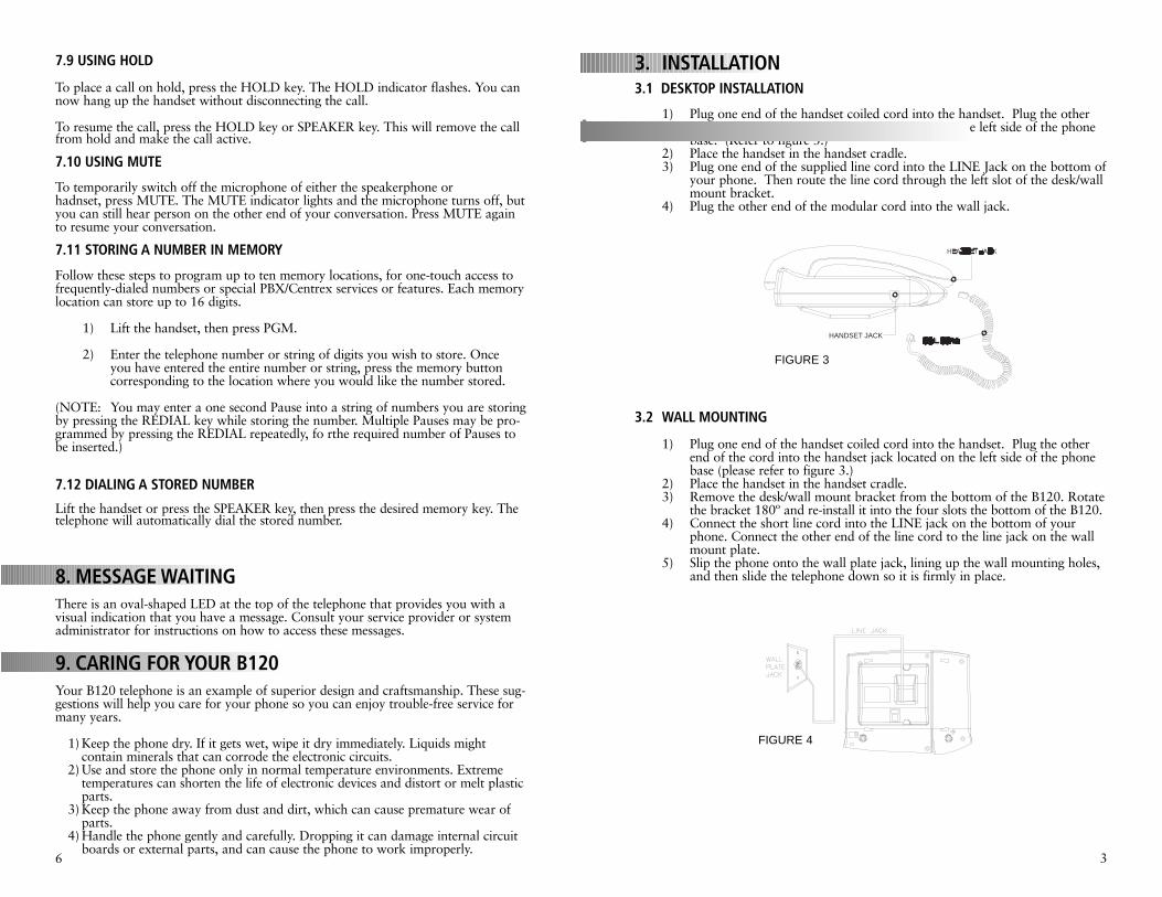
3. INSTALLATION3.1 DESKTOP INSTALLATION
1) Plug one end of the handset coiled cord into the handset. Plug the other end of the cord into the handset jack located on the left side of the phone base. (Refer to figure 3.)
2) Place the handset in the handset cradle.3) Plug one end of the supplied line cord into the LINE Jack on the bottom of
your phone. Then route the line cord through the left slot of the desk/wall mount bracket.
4) Plug the other end of the modular cord into the wall jack.
3.2 WALL MOUNTING
1) Plug one end of the handset coiled cord into the handset. Plug the other end of the cord into the handset jack located on the left side of the phone base (please refer to figure 3.)
2) Place the handset in the handset cradle.3) Remove the desk/wall mount bracket from the bottom of the B120. Rotate
the bracket 180º and re-install it into the four slots the bottom of the B120.4) Connect the short line cord into the LINE jack on the bottom of your
phone. Connect the other end of the line cord to the line jack on the wall mount plate.
5) Slip the phone onto the wall plate jack, lining up the wall mounting holes, and then slide the telephone down so it is firmly in place.
3
HANDSET JACK
FIGURE 3
FIGURE 4
7.9 USING HOLD
To place a call on hold, press the HOLD key. The HOLD indicator flashes. You cannow hang up the handset without disconnecting the call.
To resume the call, press the HOLD key or SPEAKER key. This will remove the callfrom hold and make the call active.
7.10 USING MUTE
To temporarily switch off the microphone of either the speakerphone or hadnset, press MUTE. The MUTE indicator lights and the microphone turns off, butyou can still hear person on the other end of your conversation. Press MUTE againto resume your conversation.
7.11 STORING A NUMBER IN MEMORY
Follow these steps to program up to ten memory locations, for one-touch access to frequently-dialed numbers or special PBX/Centrex services or features. Each memory location can store up to 16 digits.
1) Lift the handset, then press PGM.
2) Enter the telephone number or string of digits you wish to store. Onceyou have entered the entire number or string, press the memory button corresponding to the location where you would like the number stored.
(NOTE: You may enter a one second Pause into a string of numbers you are storingby pressing the REDIAL key while storing the number. Multiple Pauses may be pro-grammed by pressing the REDIAL repeatedly, fo rthe required number of Pauses tobe inserted.)
7.12 DIALING A STORED NUMBER
Lift the handset or press the SPEAKER key, then press the desired memory key. Thetelephone will automatically dial the stored number.
8. MESSAGE WAITINGThere is an oval-shaped LED at the top of the telephone that provides you with avisual indication that you have a message. Consult your service provider or systemadministrator for instructions on how to access these messages.
9. CARING FOR YOUR B120Your B120 telephone is an example of superior design and craftsmanship. These sug-gestions will help you care for your phone so you can enjoy trouble-free service formany years.
1) Keep the phone dry. If it gets wet, wipe it dry immediately. Liquids mightcontain minerals that can corrode the electronic circuits.
2) Use and store the phone only in normal temperature environments. Extreme temperatures can shorten the life of electronic devices and distort or melt plastic parts.
3) Keep the phone away from dust and dirt, which can cause premature wear of parts.
4) Handle the phone gently and carefully. Dropping it can damage internal circuit boards or external parts, and can cause the phone to work improperly.
6
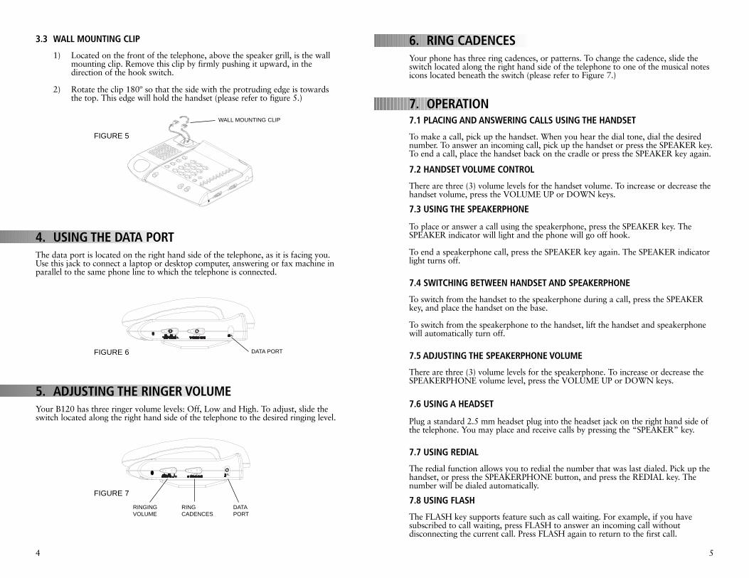
3.3 WALL MOUNTING CLIP
1) Located on the front of the telephone, above the speaker grill, is the wall mounting clip. Remove this clip by firmly pushing it upward, in thedirection of the hook switch.
2) Rotate the clip 180º so that the side with the protruding edge is towards the top. This edge will hold the handset (please refer to figure 5.)
4. USING THE DATA PORTThe data port is located on the right hand side of the telephone, as it is facing you.Use this jack to connect a laptop or desktop computer, answering or fax machine inparallel to the same phone line to which the telephone is connected.
5. ADJUSTING THE RINGER VOLUMEYour B120 has three ringer volume levels: Off, Low and High. To adjust, slide theswitch located along the right hand side of the telephone to the desired ringing level.
6. RING CADENCESYour phone has three ring cadences, or patterns. To change the cadence, slide theswitch located along the right hand side of the telephone to one of the musical notesicons located beneath the switch (please refer to Figure 7.)
7. OPERATION7.1 PLACING AND ANSWERING CALLS USING THE HANDSET
To make a call, pick up the handset. When you hear the dial tone, dial the desirednumber. To answer an incoming call, pick up the handset or press the SPEAKER key.To end a call, place the handset back on the cradle or press the SPEAKER key again.
7.2 HANDSET VOLUME CONTROL
There are three (3) volume levels for the handset volume. To increase or decrease the handset volume, press the VOLUME UP or DOWN keys.
7.3 USING THE SPEAKERPHONE
To place or answer a call using the speakerphone, press the SPEAKER key. TheSPEAKER indicator will light and the phone will go off hook.
To end a speakerphone call, press the SPEAKER key again. The SPEAKER indicatorlight turns off.
7.4 SWITCHING BETWEEN HANDSET AND SPEAKERPHONE
To switch from the handset to the speakerphone during a call, press the SPEAKERkey, and place the handset on the base.
To switch from the speakerphone to the handset, lift the handset and speakerphonewill automatically turn off.
7.5 ADJUSTING THE SPEAKERPHONE VOLUME
There are three (3) volume levels for the speakerphone. To increase or decrease theSPEAKERPHONE volume level, press the VOLUME UP or DOWN keys.
7.6 USING A HEADSET
Plug a standard 2.5 mm headset plug into the headset jack on the right hand side ofthe telephone. You may place and receive calls by pressing the “SPEAKER” key.
7.7 USING REDIAL
The redial function allows you to redial the number that was last dialed. Pick up thehandset, or press the SPEAKERPHONE button, and press the REDIAL key. Thenumber will be dialed automatically.
7.8 USING FLASH
The FLASH key supports feature such as call waiting. For example, if you havesubscribed to call waiting, press FLASH to answer an incoming call withoutdisconnecting the current call. Press FLASH again to return to the first call.
4 5
FIGURE 5
FIGURE 6
FIGURE 7
WALL MOUNTING CLIP
DATA PORT
RINGINGVOLUME
RINGCADENCES
DATAPORT