single parallel to mains – sw configuration...
TRANSCRIPT

Compact Controller for Stand-by and Parallel Operating Gen-sets
Inteli New Technology Modular Gen-set Controller
Single Parallel to Mains – SW configuration SPtM
IG-NT, IG-NTC, IG-EE, IG-EEC, IS-NT,IG-NT-BB, IG-NTC-BB, IS-NTC-BB
Software version IGS-NT-2.5, January 2011
REFERENCE GUIDE
Copyright © 2005 ComAp s.r.o.
ComAp, spol. s r.o. Kundratka 2359/17, 180 00 Praha 8, Czech Republic
Tel: +420 266 012 111, Fax: +420 266 316 647Technical support hotline: +420 266 012 666
E-mail: [email protected], www.comap.cz
Inteli NT SPtM, SW Version 2.5, ©ComAp –January 2011 IGS-NT-SPtM-2.5-Reference Guide.PDF
2
Table of Contents Table of Contents ...............................................................................................................................................2 General guidelines..............................................................................................................................................4
What is described in this manual? .................................................................................................................4 General description ............................................................................................................................................6
Basic description of SPtM application............................................................................................................6 Available related documentation....................................................................................................................7
Functions ............................................................................................................................................................8 OFF-MAN-AUT-TEST mode ..........................................................................................................................8 Active Power control modes in SPtM...........................................................................................................10 Power derating .............................................................................................................................................13 Engine states................................................................................................................................................14 PLC functions...............................................................................................................................................21 Multi language support.................................................................................................................................22 ECU interface customizing...........................................................................................................................22
Protections and Alarm management ................................................................................................................23 Gen-set operation states ..................................................................................................................................37 Inputs and Outputs ...........................................................................................................................................39
Virtual and physical modules .......................................................................................................................39 Binary inputs – Control.................................................................................................................................39 Binary inputs – Status information ...............................................................................................................47 Binary outputs ..............................................................................................................................................48 Binary outputs – Breaker control..................................................................................................................49 Binary outputs – Control loops.....................................................................................................................50 Binary outputs – Status information .............................................................................................................51 Binary outputs – Fixed protection outputs....................................................................................................55 Binary outputs – Configurable prog. States .................................................................................................59 Analog inputs................................................................................................................................................63 Analog outputs .............................................................................................................................................65 Values ..........................................................................................................................................................65 Statistics .......................................................................................................................................................66
Setpoints...........................................................................................................................................................68 ProcessControl.............................................................................................................................................68 Basic settings ...............................................................................................................................................74 Comms settings ..........................................................................................................................................78 Engine params .............................................................................................................................................83 Engine protect ..............................................................................................................................................87 Analog protect ..............................................................................................................................................91 Gener protect ...............................................................................................................................................91 Mains protect................................................................................................................................................97 AMF settings ................................................................................................................................................98 Sync/Load ctrl.............................................................................................................................................100 Sync/load control adjustment .....................................................................................................................103 Volt/PF ctrl..................................................................................................................................................106 Volt/PF control adjustment .........................................................................................................................107 Force value.................................................................................................................................................108 Load shedding............................................................................................................................................110 PLC settings...............................................................................................................................................111 Timer settings.............................................................................................................................................111 Act. calls/SMS ............................................................................................................................................111 Date/Time...................................................................................................................................................113
List of possible events ....................................................................................................................................115 Controller configuration and monitoring .........................................................................................................116
Direct connection to the PC .......................................................................................................................116 GenConfig functions...................................................................................................................................116 InteliMonitor................................................................................................................................................117

Inteli NT SPtM, SW Version 2.5, ©ComAp –January 2011 IGS-NT-SPtM-2.5-Reference Guide.PDF
3
Modbus protocol.........................................................................................................................................117 Value and setpoint codes...........................................................................................................................117 Technical data............................................................................................................................................117 Language support ......................................................................................................................................117
Inteli NT SPtM, SW Version 2.5, ©ComAp –January 2011 IGS-NT-SPtM-2.5-Reference Guide.PDF
4
General guidelines
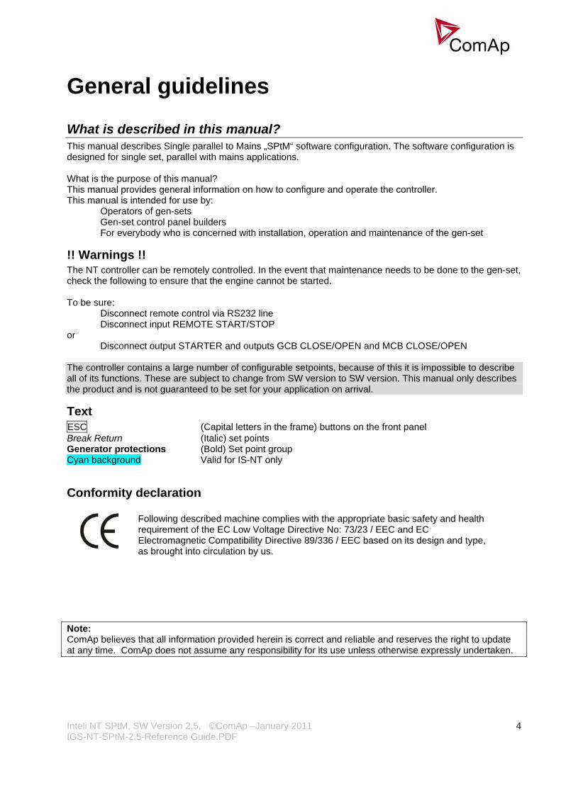
What is described in this manual? This manual describes Single parallel to Mains „SPtM“ software configuration. The software configuration is designed for single set, parallel with mains applications. What is the purpose of this manual? This manual provides general information on how to configure and operate the controller. This manual is intended for use by:
Operators of gen-sets Gen-set control panel builders For everybody who is concerned with installation, operation and maintenance of the gen-set
!! Warnings !! The NT controller can be remotely controlled. In the event that maintenance needs to be done to the gen-set, check the following to ensure that the engine cannot be started. To be sure:
Disconnect remote control via RS232 line Disconnect input REMOTE START/STOP
or Disconnect output STARTER and outputs GCB CLOSE/OPEN and MCB CLOSE/OPEN
The controller contains a large number of configurable setpoints, because of this it is impossible to describe all of its functions. These are subject to change from SW version to SW version. This manual only describes the product and is not guaranteed to be set for your application on arrival.
Text ESC (Capital letters in the frame) buttons on the front panel Break Return (Italic) set points Generator protections (Bold) Set point group Cyan background Valid for IS-NT only
Conformity declaration
Following described machine complies with the appropriate basic safety and health requirement of the EC Low Voltage Directive No: 73/23 / EEC and EC Electromagnetic Compatibility Directive 89/336 / EEC based on its design and type, as brought into circulation by us.
Note: ComAp believes that all information provided herein is correct and reliable and reserves the right to update at any time. ComAp does not assume any responsibility for its use unless otherwise expressly undertaken.
Inteli NT SPtM, SW Version 2.5, ©ComAp –January 2011 IGS-NT-SPtM-2.5-Reference Guide.PDF
5
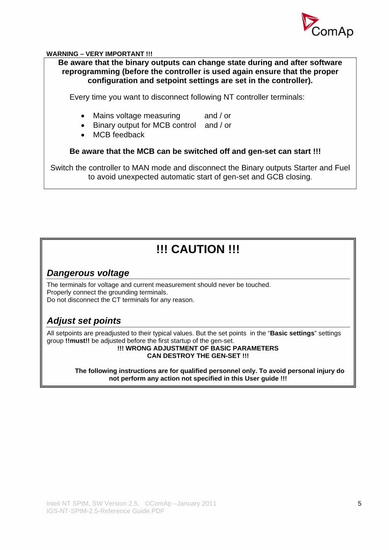
WARNING – VERY IMPORTANT !!!
Be aware that the binary outputs can change state during and after software reprogramming (before the controller is used again ensure that the proper
configuration and setpoint settings are set in the controller).
Every time you want to disconnect following NT controller terminals:
• Mains voltage measuring and / or • Binary output for MCB control and / or • MCB feedback
Be aware that the MCB can be switched off and gen-set can start !!!
Switch the controller to MAN mode and disconnect the Binary outputs Starter and Fuel to avoid unexpected automatic start of gen-set and GCB closing.
!!! CAUTION !!!
Dangerous voltage The terminals for voltage and current measurement should never be touched. Properly connect the grounding terminals. Do not disconnect the CT terminals for any reason.
Adjust set points All setpoints are preadjusted to their typical values. But the set points in the “Basic settings” settings group !!must!! be adjusted before the first startup of the gen-set.
!!! WRONG ADJUSTMENT OF BASIC PARAMETERS CAN DESTROY THE GEN-SET !!!
The following instructions are for qualified personnel only. To avoid personal injury do
not perform any action not specified in this User guide !!!

Inteli NT SPtM, SW Version 2.5, ©ComAp –January 2011 IGS-NT-SPtM-2.5-Reference Guide.PDF
6
General description
Basic description of SPtM application The SPtM application is intended for single gen-sets and includes following main features:
• Automatic startup and stop sequences with adjustable timing • Wide range of generator and engine protections, additional freely configurable protections • Parallel to the mains operation, many different load control modes (baseload, import/export control
and other) • Island operation • Integrated mains protection (mains decoupling relay) including vector shift • AMF function (automatic start if mains fails) with test feature • Two breaker control (GCB, MCB) including synchronizing • Soft loading and unloading

Inteli NT SPtM, SW Version 2.5, ©ComAp –January 2011 IGS-NT-SPtM-2.5-Reference Guide.PDF
7
Available related documentation PDF FILE DESCRIPTION
InteliMonitor-2.6-Reference Guide Reference Guide for monitoring tool
GenConfig-2.5-Reference Guide Reference Guide for configuration tool
IGS-NT-BB Communication Guide 01-2011 Communication guide for IG/IS-NT controllers. It contains information how to connect control unit and all communication features descriptions
IGS-NT-2.5 Installation Guide Installation guide for IG/IS-NT controllers. It contains technical information about controler and extension modules
IGS-NT-2.5 Application Guide Application guide for IG/IS-NT controllers. It refers to application and typical installation settings and sites structures
IGS-NT-2.0-Operator guide.pdf Operator guide for IG/IS-NT

Inteli NT SPtM, SW Version 2.5, ©ComAp –January 2011 IGS-NT-SPtM-2.5-Reference Guide.PDF
8
Functions OFF-MAN-AUT-TEST mode
OFF mode Outputs STARTER, GCB CLOSE/OPEN and FUEL SOLENOID are not energized. Genset cannot be started. If START,STOP,GCB ON/OFF,MCB ON/OFF buttons are pressed the controller will not respond. MCB behavior depends on AMF settings: MCB opens on setpoint: MAINSFAIL: When power-cut comes, MCB opens. After mains returns, MCB closes with MCB close del. GEN RUNNING: When power-cut comes, MCB stays closed. When the gen-set is running it is not possible to switch directly to OFF mode. First you have to stop the engine.
MAN mode 1) START - starts the gen-set. 2) GCB ON/OFF
If generator voltage is out of the limits (adjusted in the set point group Gener protect) controller does not respond to the GCB ON/OFF a) controller closes GCB to dead bus. b) controller starts GCB synchronizing when mains is OK and MCB is closed. Closes the GCB
when synchronized and stays running in parallel. Operational mode in parallel depends on ProcessControl setting.
c) Unloads gen-set and opens the GCB if gen-set was running in parallel to the mains. d) Opens GCB immediately if gen-set was running in island operation.
3) MCB ON/OFF a) controller closes MCB to dead bus (even if the mains voltage is out of limits). b) controller starts MCB synchronizing when gen-set is running and GCB is closed. Closes the
MCB when synchronized and stays running in parallel. Operational mode in parallel depends on ProcessControl setting.
c) Unloads gen-set and opens the MCB if gen-set was running in parallel to the mains. 4) STOP
a) When gen-set is running in parallel: transfers load to the mains, opens GCB, goes into cooling state and stops the engine.
b) When gen-set is running island (MCB is opened): opens GCB, goes into cooling state and stops the engine.
c) When engine is running unloaded: activates cooling sequence and then stops the engine. d) During cooling state causes immediate engine stop.
Hint: The genset is permitted to run unloaded for unlimited time. Controller does not automatically start the gen-set when power cut comes or REM START/STOP is closed. Controller does not automatically change the MCB state depending on mains changes. Load control in parallel depends on ProcessControl: Load ctrl PtM setpoint.
SEM In SEM mode, pressing of START or STOP buttons performs a predefined sequence: 1) START – starts the engine, synchronizes and runs in parallel. 2) STOP – softly unloads the gen-set, opens GCB, provides cooldown and stops the engine. 3) In case of mains failure and Process control: MFStart enable set to YES, allows automatic start/stop
same as in AUT mode.

Inteli NT SPtM, SW Version 2.5, ©ComAp –January 2011 IGS-NT-SPtM-2.5-Reference Guide.PDF
9
AUT mode – (Stand-by) Automatic mode is influenced by ProcessControl: Island enable, ParallelEnable, Synchro enable and MFStart enable setpoints.
No.
Isla
nd
enab
le
Par
alle
l en
able
Syn
chro
en
able
MFS
tart
enab
le
Function
1 YES YES BOTH YES SPTM application, stand-by, soft load transfer 2 NO YES BOTH X SPTM – long parallel, no Stand-by 3 YES NO NO YES SSB with break transfer;
Gen-set start is blocked. 4 NO NO NO NO NO NO BOTH NO NO NO REV NO NO YES REV NO NO YES NO YES NO NO X X YES NO NO NO YES NO NO NO
Gen-set start is blocked. Binary output Ofl StartBlck indicates those states.
Following procedure corresponds to setting No.1 from table above. 1) Mains failure is recognized Controller opens MCB when AMF settings: MCB opens on = MAINSFAIL.
a) After AMF settings:EmergStart del elapsed, Controller starts the gen-set. Controller opens MCB after engine starts when AMF settings: MCB opens on = GENRUN.
b) If mains recovers during the start-up process, Controller closes MCB again after AMF settings: MCB close del and stops the gen-set.
2) When the gen-set is above Underspeed level and the generator voltage is within limits (adjust in the set point group Gener protect) Controller closes the GCB. If the generator voltage is out of the limits for Engine params: Max stab time, Controller alarms the failure and stops the gen-set.
3) After mains recovers: a) After AMF settings: Mains ret del Controller starts synchronizing to mains and closes the MCB and
unloads the gen-set. b) After the AMF settings:BreakerOverlap delay Controller opens the GCB. c) The gen-set is cooled down and stopped.
TEST mode Use TEST mode for Gen-set start test if the Mains is OK or to transfer the load to the gen-set when Mains fail is announced in advance. Hint: The controller does not respond to GCB ON/OFF , STOP, START in Return To mains = ENABLED. Engine automatically starts, when TEST mode is selected. Engine can start automatically without warning when pressing FAULT RESET after shut down alarm.
Mains parameters out of limits during synchronising In case that mains parameters get out of permitted limits during synchronizing to mains (reverse or forward), the regulation of gen-set speed and voltage according to mains frequency and voltage is interrupted. During the state, when parameters reach out of limits, until “Mains fail” is issued, the engine speed and voltage regulation output is kept on the last value.
Baseload Process control: Load ctrl PtM = BASELOAD Gen-set power is kept at value given by Process control:Base load setpoint.

Inteli NT SPtM, SW Version 2.5, ©ComAp –January 2011 IGS-NT-SPtM-2.5-Reference Guide.PDF
10
Internal Import export ProcessControl: Load ctrl PtM = IMP/EXP Process control: IE measurement = IM3 CT INPUT Gen-set power is controlled to keep the import load at the level given by setpoint Process control: Import load value. Controller measures Import/Export value via the current transformer connected to In/Im3 terminal. The value of L3 is then multiplied by 3 to give an estimation of the actual Imp/Exp.
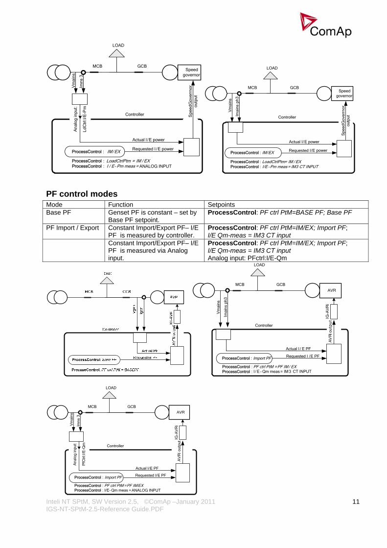
Active Power control modes in SPtM Mode Function Setpoints Warming The controller limits gen-set power for
requested time or until the water temperature reach the requested value. After warming the gen-set goes to the requested (e.g. Baseload) power.
Engine params: Warming load; Warming temp; Max warm time
Baseload Genset power is constant - set by Baseload setpoint.
ProcessControl: Load ctrl PtM=BASELOAD; Base load
ANEXT Baseload Gen-set power is set via Analog input. ProcessControl: Load ctrl ANEXT Baseload; Analog input: LdCtrlAnextBld
Import / Export Import/Export value is constant – I/E power is measured by controller.
ProcessControl: Load ctrl PtM=IM/EX; Import load; I/E Pm-meas = IM3 CT INPUT
ANEXT Import / Export
Import/Export value is constant – I/E power is measured via Analog input.
ProcessControl: Load ctrl PtM=IM/EX; Import load; I/E Pm-meas = ANALOG INPUT Analog input: LdCtrl:I/E-Pm
Peak shaving Automatic gen-set start/stop based on object (load) consumption.
ProcessControl: PeakLevelStart; PeakLevelStop; PeakAutS/S del
Export limit Limits export to the mains in the Baseload mode.
ProcessControl: Export limit = ENABLE
Requested power
Actual power
Speedgovernor
ProcessControl: Load ctrl PtM = ANEXT BASELOAD
LOAD
GCBMCB
Controller
Inteli NT SPtM, SW Version 2.5, ©ComAp –January 2011 IGS-NT-SPtM-2.5-Reference Guide.PDF
11
Spe
edG
over
rnor
ou
tput
Speed governor
LOAD
GCBMCB
Controller
LdC
trl:I
/E-P
m
Ana
log
inpu
t:V
mai
ns
Imns
3
LoadCtrlPtm = IM / EXI / E- Pm meas = ANALOG INPUT
ProcessControl : ProcessControl :
ProcessControl : IM/ EXRequested I /E power
Actual I /E power
Spe
edG
over
rnor
ou
tput
Speed governor
LoadCtrlPtm = IM / EX
LOAD
GCBMCB
Controller
Vm
ains
Imai
ns p
h3
ProcessControl : IM/EX
ProcessControl : I/E - Pm meas = IM3 CT INPUTProcessControl :
Requested I/E power
Actual I/E power
PF control modes Mode Function Setpoints Base PF Genset PF is constant – set by
Base PF setpoint. ProcessControl: PF ctrl PtM=BASE PF; Base PF
PF Import / Export Constant Import/Export PF– I/E PF is measured by controller.
ProcessControl: PF ctrl PtM=IM/EX; Import PF; I/E Qm-meas = IM3 CT input
Constant Import/Export PF– I/E PF is measured via Analog input.
ProcessControl: PF ctrl PtM=IM/EX; Import PF; I/E Qm-meas = IM3 CT input Analog input: PFctrl:I/E-Qm
ProcessControl : Import PF
AVR
ProcessControl : ProcessControl :
LOAD
GCBMCB
IG-A
VR
iController
Vm
ains
Imai
ns p
h3
PF ctrl PtM = PF IM / EX
Actual I / E PF
Requested I /E PF
I / E - Qm meas = IM3 CT INPUT
AV
Rio
utp
ut
LOAD
GCBMCB
Import PF
AVR
AV
Ri o
utpu
t
Controller
PfC
trl:I
/E-Q
m
Ana
log
inpu
t:V
mai
ns
Imns
3
Actual I/E PF
Requested I/E PF
PF ctrl PtM = PF IM/EXProcessControl :
ProcessControl :
ProcessControl : I/E-Qm meas = ANALOG INPUT
IG-A
VR
i
Inteli NT SPtM, SW Version 2.5, ©ComAp –January 2011 IGS-NT-SPtM-2.5-Reference Guide.PDF
12
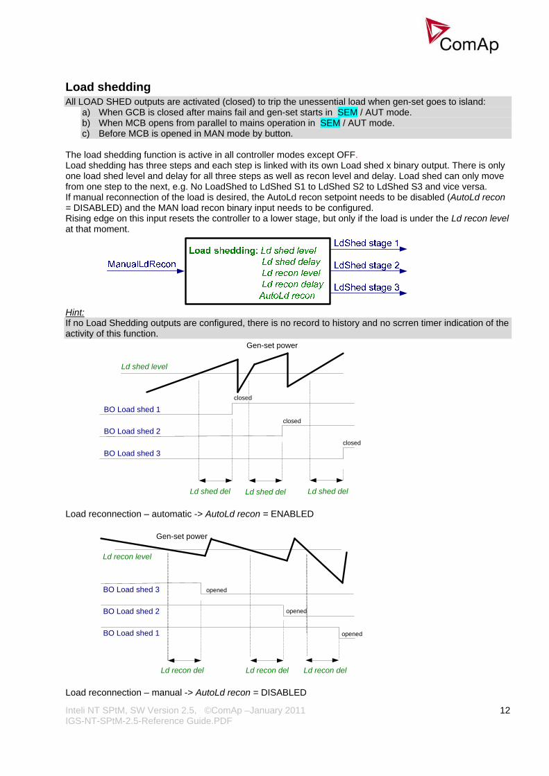
Load shedding All LOAD SHED outputs are activated (closed) to trip the unessential load when gen-set goes to island:
a) When GCB is closed after mains fail and gen-set starts in SEM / AUT mode. b) When MCB opens from parallel to mains operation in SEM / AUT mode. c) Before MCB is opened in MAN mode by button.
The load shedding function is active in all controller modes except OFF. Load shedding has three steps and each step is linked with its own Load shed x binary output. There is only one load shed level and delay for all three steps as well as recon level and delay. Load shed can only move from one step to the next, e.g. No LoadShed to LdShed S1 to LdShed S2 to LdShed S3 and vice versa. If manual reconnection of the load is desired, the AutoLd recon setpoint needs to be disabled (AutoLd recon = DISABLED) and the MAN load recon binary input needs to be configured. Rising edge on this input resets the controller to a lower stage, but only if the load is under the Ld recon level at that moment.
Hint: If no Load Shedding outputs are configured, there is no record to history and no scrren timer indication of the activity of this function.
Ld shed del Ld shed del Ld shed del
BO Load shed 1
BO Load shed 2
BO Load shed 3
Gen-set power
closed
closed
closed
Ld shed level
Load reconnection – automatic -> AutoLd recon = ENABLED
Gen-set power
Ld recon level
BO Load shed 3
BO Load shed 2
BO Load shed 1
opened
opened
opened
Ld recon del Ld recon delLd recon del Load reconnection – manual -> AutoLd recon = DISABLED

Inteli NT SPtM, SW Version 2.5, ©ComAp –January 2011 IGS-NT-SPtM-2.5-Reference Guide.PDF
13
Test on load – SPtM Affects the behavior in TEST mode. Before the activation of this function
1. adjust setpoint AMF settings: ReturnTo mains = DISABLED 2. adjust Process control: MFStart enable = YES. 3. switch controller to Test on load mode (see drawing below)
Gen-set starts and goes to load (synchronizes to the mains, closes GCB and opens MCB) automatically when this input is closed even if Mains is OK. Gen-set stays running in parallel with mains during the soft load transfer from the mains to the gen-set until Import power = 0. When the load is bigger than Nominal power, MCB stays closed, BO WrnTstOnLdFail is closed and warning message is issued (WrnTstOnLdFail). This message is issued also when GCB is closed and Load Ramp timer is counted down. When the controller is switched from Test on load mode (and Mains is OK), it synchronizes MCB, stays running in parallel for BreakerOverlap time (soft load transfer), opens GCB, cools down and stops. During the load transfer from the gen-set to the mains can be BreakerOverlap time shortened due to the influence of: Load ramp, GCB open level, GCB open del setpoints.
Hint: It is possible to configure both binary inputs (Remote TEST and Test on load) to only one controller physical binary input internally.
Power derating This function linearly decreases genset nominal power according to analog input value. Gen-set power starts decreasing when temperature measured by Analog input PowerDeratingX exceeds DeratingX strt value. Gen-set power is at DeratedX pwr value when temperature measured by Analog input Power deratingX is equal or higher than DeratingX end value. Hint: To use Power derating function configure at first Analog input PowerDeratingX to any IGS-NT or IS-AIN analog input terminal by GenConfig. When Power derating function is active the generator overload protection is based on the Derated power! ! ! Derated power value Pg derated is visible in the controller measure screen.

Inteli NT SPtM, SW Version 2.5, ©ComAp –January 2011 IGS-NT-SPtM-2.5-Reference Guide.PDF
14
When derating function is not active the Derating power is equal to Nominal power. Example : Nomin power = 200 kW, Derating1 strt = 70 °C, Derating1 end = 100 °C, Derated1 pwr = 70 %. Genset is running at Nominal power 200 kW. When temperature reached 70 °C the genset power starts decreasing. When temperature reached 100 °C genset runs at 70 % of Nominal power = 140 kW. When temperature increased above DeratingX end temperature level, gen-set power stays at DeratedX pwr level 140 kW.
Temperature derating function decreases genset power depend on setpoints DeratingX strt, DeratingX end and DeratedX pwr. Temperature derating starts at DeratingX strt temperature. At DeratingX end temperature runs genset at DeratedX pwr level. Above DeratingX end temperature Genset runs at constant DeratedX pwr.
Engine states
Engine prelubrication
Hint: To use Prelubrication, configure Binary output PRELUBR PUMP first. Prelubrication is disabled in controller OFF mode or if Prelubr time is set to zero. Binary output PRELUBR PUMP is opened when engine is running. Prelubrication cycle starts with PrelubrPause after engine stop. Prelubrication cycle starts immediately when controller power supply is switched on or when mode changes from OFF to MAN or AUT or after Emergency stop was reset. An Alarmlist message “Not lubricated” is active until this first lubrication cycle has been completed.
Engine cooling
Engine warming
Inteli NT SPtM, SW Version 2.5, ©ComAp –January 2011 IGS-NT-SPtM-2.5-Reference Guide.PDF
15
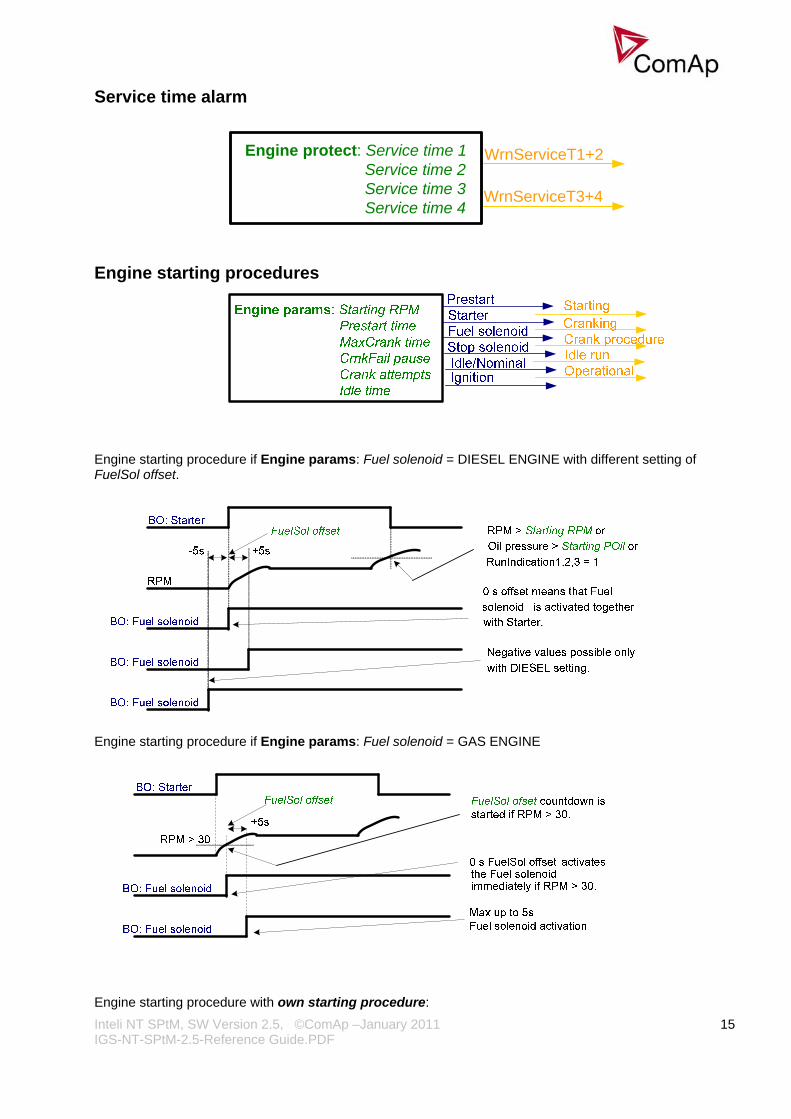
Service time alarm
Engine protect: Service time 1Service time 2Service time 3Service time 4
WrnServiceT3+4
WrnServiceT1+2
Engine starting procedures
Engine starting procedure if Engine params: Fuel solenoid = DIESEL ENGINE with different setting of FuelSol offset.
Engine starting procedure if Engine params: Fuel solenoid = GAS ENGINE
Engine starting procedure with own starting procedure:

Inteli NT SPtM, SW Version 2.5, ©ComAp –January 2011 IGS-NT-SPtM-2.5-Reference Guide.PDF
16
Engine is started after Starting RPM reach starting leve or other condition. BO: Starter is deactivated only if one of those condition is fulfilled.
Generator nominal voltage is 231V but during Cranking is forced to 1000V until engine in Idle state (at least one of condition has to be fulfilled). Unsuccessful start – no Engine params: Starting RPM reached
Unsuccessful start – RPM disappeared before/after Underspeed protection got active:
RPM dropped under Starting RPM level and Underspeed enabled
-> protection activated.
Underspeed unblocking
BO: Fuel solenoid
RPM
BO: Starter
Start fail activated because ofRPM loss.
BO: Start fail
Starting RPM level.
Underspeed protection is not yetActive. Underspeed is detectedonly if RPM <= 2 and othersigns of moving enginepresent = „still engine“.

Inteli NT SPtM, SW Version 2.5, ©ComAp –January 2011 IGS-NT-SPtM-2.5-Reference Guide.PDF
17
Underspeed protection unblocking if Idle time < 5s:
Underspeed protection unblocking if Idle time > 5s:
Transition Idle -> Nominal RPM, protections unblocking:

Inteli NT SPtM, SW Version 2.5, ©ComAp –January 2011 IGS-NT-SPtM-2.5-Reference Guide.PDF
18
Preventilation (if Fuel solenoid = GAS):
Ventilation (if Fuel solenoid = GAS ENGINE):

Inteli NT SPtM, SW Version 2.5, ©ComAp –January 2011 IGS-NT-SPtM-2.5-Reference Guide.PDF
19
Engine stopping procedures Normal engine stop:
Pick-up sensor fault – forced engine stop:
Normal engine stop, but Stop time is set too short:

Inteli NT SPtM, SW Version 2.5, ©ComAp –January 2011 IGS-NT-SPtM-2.5-Reference Guide.PDF
20
Unsuccessful engine stop:
BO: Stop pulse
5s
BO: Stop solenoid
Stop time
BO: Fuel solenoid
RPM + pick - up signal > 0
Stop command issued, but no reaction.
The cyclic stop attempts continue until the engine actually stops.Stop time
In this moment the Stop timeelapsed, but the engine is still moving. „Sd Stop fail“ alarm
appears.The fuel or stop valve probably stucked in wrong position.
“Forced” stop in still state:
Spontaneous engine start-up:
Inteli NT SPtM, SW Version 2.5, ©ComAp –January 2011 IGS-NT-SPtM-2.5-Reference Guide.PDF
21
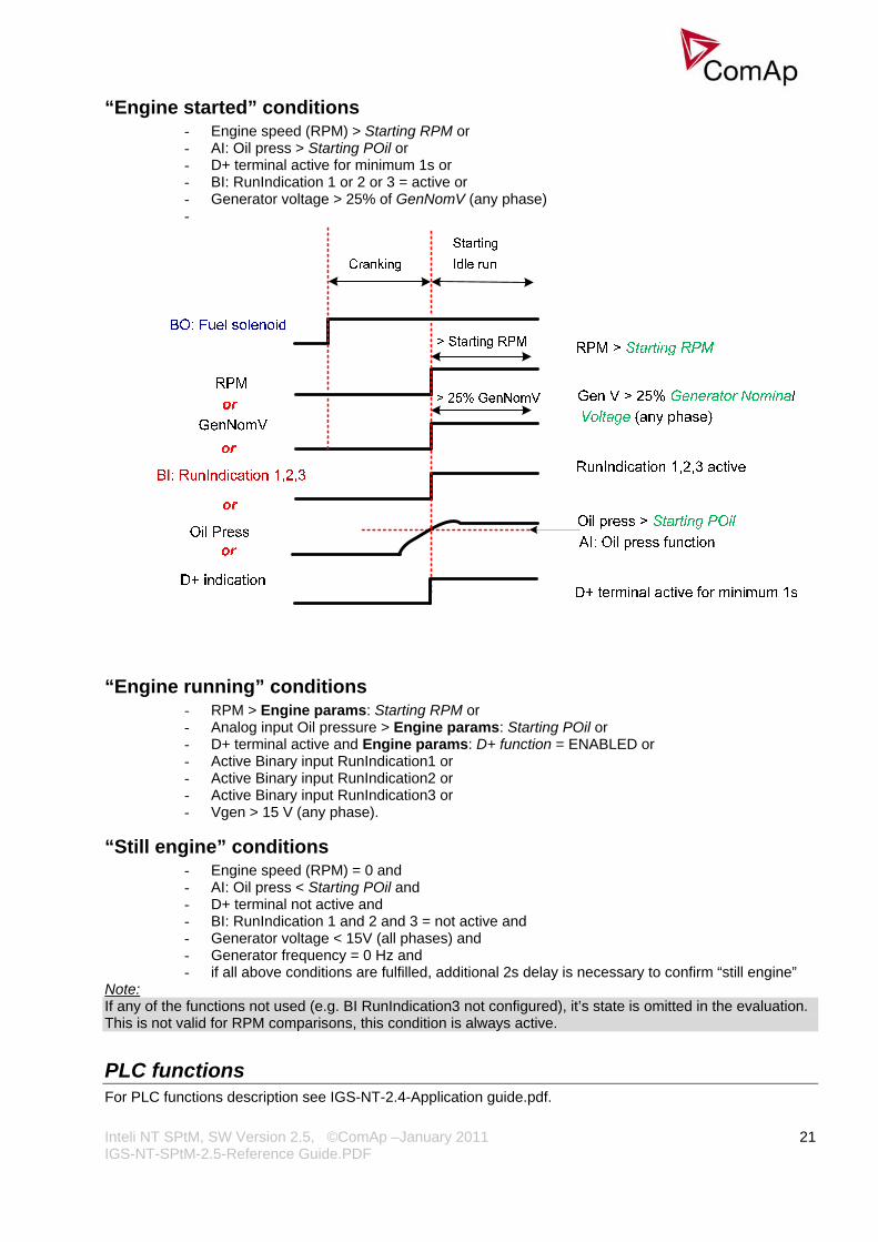
“Engine started” conditions - Engine speed (RPM) > Starting RPM or - AI: Oil press > Starting POil or - D+ terminal active for minimum 1s or - BI: RunIndication 1 or 2 or 3 = active or - Generator voltage > 25% of GenNomV (any phase) -
“Engine running” conditions - RPM > Engine params: Starting RPM or - Analog input Oil pressure > Engine params: Starting POil or - D+ terminal active and Engine params: D+ function = ENABLED or - Active Binary input RunIndication1 or - Active Binary input RunIndication2 or - Active Binary input RunIndication3 or - Vgen > 15 V (any phase).
“Still engine” conditions - Engine speed (RPM) = 0 and - AI: Oil press < Starting POil and - D+ terminal not active and - BI: RunIndication 1 and 2 and 3 = not active and - Generator voltage < 15V (all phases) and - Generator frequency = 0 Hz and - if all above conditions are fulfilled, additional 2s delay is necessary to confirm “still engine”
Note: If any of the functions not used (e.g. BI RunIndication3 not configured), it’s state is omitted in the evaluation. This is not valid for RPM comparisons, this condition is always active.
PLC functions For PLC functions description see IGS-NT-2.4-Application guide.pdf.
Inteli NT SPtM, SW Version 2.5, ©ComAp –January 2011 IGS-NT-SPtM-2.5-Reference Guide.PDF
22
Multi language support NT family controllers support up to five Languages that is possible to switch during controller duty. Every terminal (i.e. Remote display or PC-InteliMonitor) can be switched to different language. Use PC-GenConfig - Translator tool to translate texts to another language. Default application archives contain all texts in English only.
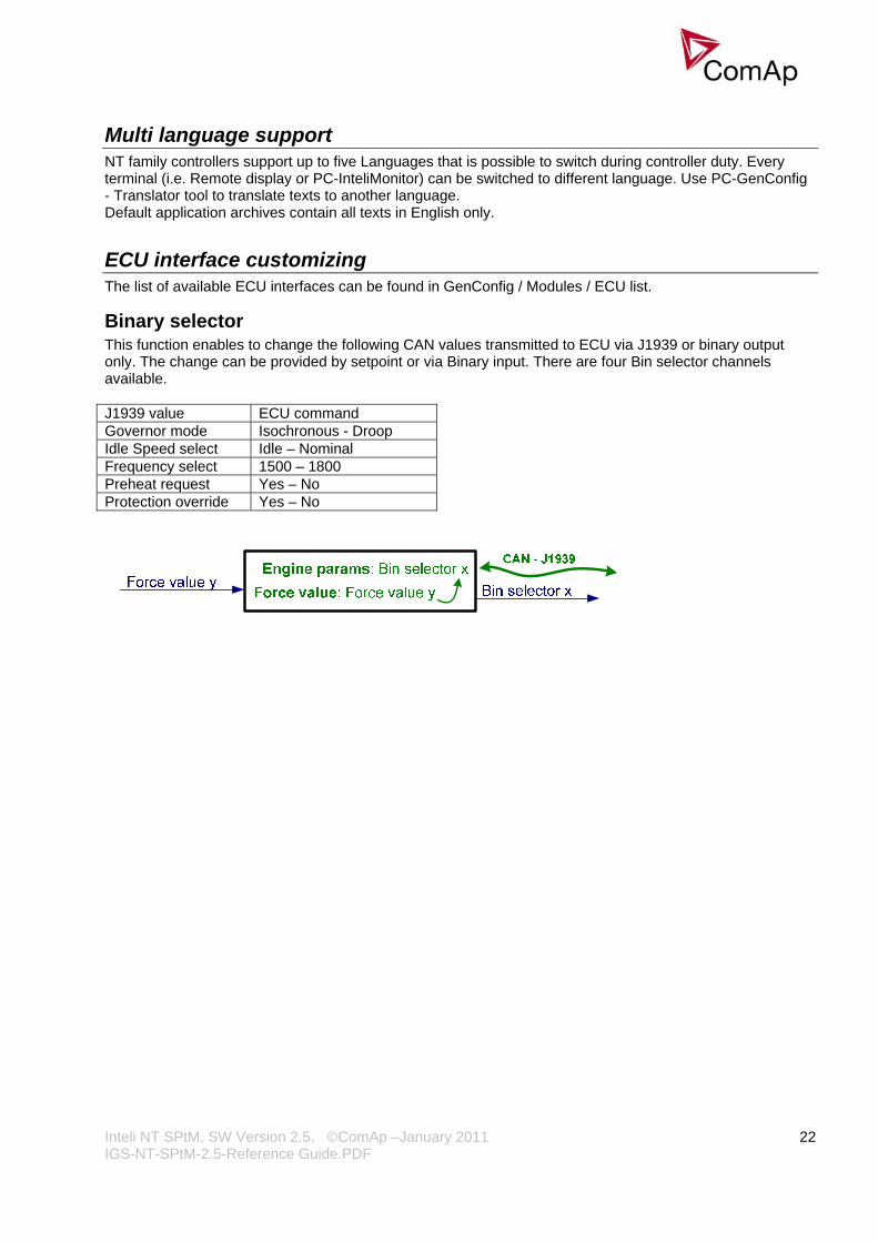
ECU interface customizing The list of available ECU interfaces can be found in GenConfig / Modules / ECU list.
Binary selector This function enables to change the following CAN values transmitted to ECU via J1939 or binary output only. The change can be provided by setpoint or via Binary input. There are four Bin selector channels available. J1939 value ECU command Governor mode Isochronous - Droop Idle Speed select Idle – Nominal Frequency select 1500 – 1800 Preheat request Yes – No Protection override Yes – No

Inteli NT SPtM, SW Version 2.5, ©ComAp –January 2011 IGS-NT-SPtM-2.5-Reference Guide.PDF
23
Protections and Alarm management ComAp gen-set controllers provide following range of generator protections. For each protection adjustable limit and time delay are available.
ANSI CODE PROTECTION IG-NT, IG-NTC, IG-NT-BB, IG-NTC-BB
IS-NT-BB, IS-NTC-BB
59 Overvoltage • •
27 Undervoltage • •
47 Voltage Assymetry • •
81H Overfrequency • •
81L Underfrequency • •
50+51 Overcurrent • •
46 Current Unbalance • •
32 Overload • •
50N+64 Earth Fault • •
32R Reverse Power • •
25 Synchronism Check • •
47 Phase Rotation • •
37 Undercurrent •@ •@
55 Power Factor •@ •@
71 Gas (Fuel) Level • • Note: − - excluded; • - included * - available in SPtM, SPI, MINT applications # - available in SPtM, MINT, MEXT applications x - not available in SPtM application @ - can be created using universal protections
Protection groups There are two groups of protections in the controller: fix and universal (configurable) PROTECTION GROUP CONFIGURABILITY SETTINGS
Analogu protection Configurable Analog protect
Generator protection Configurable Gener protect
Mains protections Configurable Mains protect
Fix protections Fix Engine params, Gener protect, Mains protect, Analog protect

Inteli NT SPtM, SW Version 2.5, ©ComAp –January 2011 IGS-NT-SPtM-2.5-Reference Guide.PDF
24
Alarm types ALARM/EVENT KIND LEVEL DESCRIPTION
Warning 1 The alarm appears in the Alarmlist and is recorded into the history log. Activates the output Common Wrn as well as the standard alarm outputs.
Alarm Only 1 The alarm appears only in the Alarmlist. Activates the output Common Al as well as the standard alarm outputs.
HistRecOnly 1 The event is recorded into the history. Activates the output Common Hst for one second. Standard alarm outputs are not activated.
AL indication 1
The event is only indicated in the Alarmlist. It disappear for the alarmist automatically as soon as the cause disappears. Standard alarm outputs are not activated.
A+H indication 1
The event is only indicated in the Alarmlist and recorded into the history log. It disappear for the alarmist automatically as soon as the cause disappears. Standard alarm outputs are not activated.
Shutdown 2
The alarm appears in the Alarmlist and is recorded into the history log. It causes immediate stop of the gen-set without unloading and cooling phase. The gen-set can't be started again while there is a Shutdown alarm in the Alarmlist. Activates the output Common Sd as well as the standard alarm outputs.
Slow Stop 2
The alarm appears in the Alarmlist and is recorded into the history log. It causes stop of the gen-set by the standard stop sequence, i.e. including unloading and cooling phase. The gen-set can't be started again while there is a Slow stop alarm in the Alarmlist. Activates the output Common Stp as well as the standard alarm outputs.
Off Load 2
The event appears in the Alarmlist and is recorded into the history log. It does not require confirmation, diappears by itself. It causes immediate opening of the GCB. In AUT and SEM modes the gen-set remains running for 60 seconds and then it is stopped by the standard stop sequence. In MAN mode the gen-set remains running until the operator changes it's operational state manually. If the controller is in AUT or SEM mode and all previously active Off load alarms disappeared the gen-set is automatically started back and connected to the load if the condition for the gen-set to be running persists (e.g. Rem start/stop is active ..). This event is used to put the gen-set temporarily off the load for any reason. Activates the output Common OfL.
Inteli NT SPtM, SW Version 2.5, ©ComAp –January 2011 IGS-NT-SPtM-2.5-Reference Guide.PDF
25
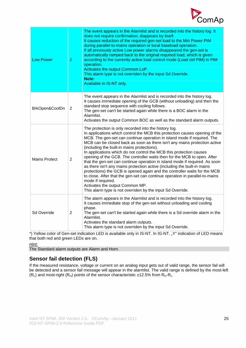
Low Power 2
The event appears in the Alarmlist and is recorded into the history log. It does not require confirmation, diappears by itself. It causes reduction of the required gen-set load to the Min Power PtM during parallel-to-mains operation or local baseload operation. If all previously active Low power alarms disappeared the gen-set is automatically ramped back to the original required load, which is given according to the currently active load control mode (Load ctrl PtM) in PtM operation. Activates the output Common LoP. This alarm type is not overriden by the input Sd Override. Note: Available in IS-NT only.
BrkOpen&CoolDn 2
The event appears in the Alarmlist and is recorded into the history log. It causes immediate opening of the GCB (without unloading) and then the standard stop sequence with cooling follows. The gen-set can't be started again while there is a BOC alarm in the Alarmlist. Activates the output Common BOC as well as the standard alarm outputs.
Mains Protect 2
The protection is only recorded into the history log. In applications which control the MCB this protection causes opening of the MCB. The gen-set can continue operation in island mode if required. The MCB can be closed back as soon as there isn't any mains protection active (including the built-in mains protections). In applications which do not control the MCB this protection causes opening of the GCB. The controller waits then for the MCB to open. After that the gen-set can continue operation in island mode if required. As soon as there isn't any mains protection active (including the built-in mains protections) the GCB is opened again and the controller waits for the MCB to close. After that the gen-set can continue operation in parallel-to-mains mode if required. Activates the output Common MP. This alarm type is not overriden by the input Sd Override.
Sd Override 2
The alarm appears in the Alarmlist and is recorded into the history log. It causes immediate stop of the gen-set without unloading and cooling phase. The gen-set can't be started again while there is a Sd override alarm in the Alarmlist. Activates the standard alarm outputs. This alarm type is not overriden by the input Sd Override.
*) Yellow color of Gen-set indication LED is available only in IS-NT. In IG-NT, „Y“ indication of LED means that both red and green LEDs are on. Hint: The Standard alarm outputs are Alarm and Horn.
Sensor fail detection (FLS) If the measured resistance, voltage or current on an analog input gets out of valid range, the sensor fail will be detected and a sensor fail message will appear in the alarmlist. The valid range is defined by the most-left (RL) and most-right (RH) points of the sensor characteristic ±12.5% from RH-RL.

Inteli NT SPtM, SW Version 2.5, ©ComAp –January 2011 IGS-NT-SPtM-2.5-Reference Guide.PDF
26
Hint: The sensor fail alarm does not influence the gen-set operation
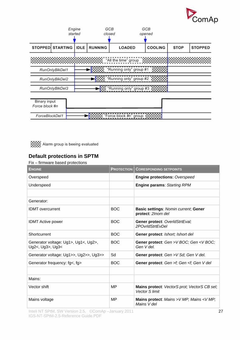
Blocking types BLOCKING TYPE DESCRIPTION
All the time The alarms are beeing evaluated all the time the controller is switched on.
RunOnlyBlkDel1 The alarms are beeing evaluated only while the gen-set is running. The evaluation begins RunOnlyBlkDel1 seconds after the engine has been started.
RunOnlyBlkDel2 The alarms are beeing evaluated only while the gen-set is running. The evaluation begins RunOnlyBlkDel2 seconds after the engine has been started.
RunOnlyBlkDel3 The alarms are beeing evaluated only while the gen-set is running. The evaluation begins RunOnlyBlkDel3 seconds after the engine has been started.
Force block 1 The alarms are beeing evaluated while the input Force block 1 is not active. The evaluation begins ForceBlockDel1 seconds after the input has been deactivated.
Force block 2 The alarms are beeing evaluated while the input Force block 2 is not active. The evaluation begins ForceBlockDel2 seconds after the input has been deactivated.
Force block 3 The alarms are beeing evaluated while the input Force block 3 is not active. The evaluation begins ForceBlockDel3 seconds after the input has been deactivated.
El. prot
The alarms are beeing evaluated while the generator is expected to provide correct voltage and frequency. That means the alarms start to be evaluated after transition form Idle to Running phase when the period of Max stab time has already elapsed, remain beeing evaluated while the gen-set is running at nominal speed (regardless of GCB position) and stop to be evaluated by transition to the Cooling phase.
Inteli NT SPtM, SW Version 2.5, ©ComAp –January 2011 IGS-NT-SPtM-2.5-Reference Guide.PDF
27
Default protections in SPTM Fix – firmware based protections ENGINE PROTECTION CORESPONDING SETPOINTS
Overspeed SD Engine protections: Overspeed
Underspeed SD Engine params: Starting RPM
Generator:
IDMT overcurrent BOC Basic settings: Nomin current; Gener protect: 2Inom del
IDMT Active power BOC Gener protect: OverldStrtEval; 2POvrldStrtEvDel
Shortcurrent BOC Gener protect: Ishort; Ishort del
Generator voltage: Ug1>, Ug1<, Ug2>, Ug2<, Ug3>, Ug3<
BOC Gener protect: Gen >V BOC; Gen <V BOC; Gen V del.
Generator voltage: Ug1>>, Ug2>>, Ug3>> Sd Gener protect: Gen >V Sd; Gen V del.
Generator frequency: fg<, fg> BOC Gener protect: Gen >f; Gen <f; Gen V del
Mains:
Vector shift MP Mains protect: VectorS prot; VectorS CB sel; Vector S limit
Mains voltage MP Mains protect: Mains >V MP; Mains <V MP; Mains V del

Inteli NT SPtM, SW Version 2.5, ©ComAp –January 2011 IGS-NT-SPtM-2.5-Reference Guide.PDF
28
Mains frequency MP Mains protect: Mains >f; Mains <f; Mains f del
Default - configurable
Reverse power (UnivState 1) BOC Gener protect: Reverse power; ReversePwr del
Batt <V, Batt >V (UnivState 2) Wrn Analog protect: Batt >V; Batt <V; Batt V del
EarthFaultCurr (UnivState 5) BOC Gener protect: EarthFaultCurr; EthCurr del
Gen Current unbalance BOC Gener protect: Gen I unbal; Gen I unb del
Gen Voltage unbalance BOC Gener protect: Gen V unbal;Gen V unb del
Mains Voltage unbalance BOC Mains protect: Mains V unbal; Mains Vunb del
Mains voltage and frequency protections - limits and indications Basic settings: VoltProtselect = PHASE-NEUTRAL
MP L1 underMP L2 underMP L3 underMP L1 overMP L2 overMP L3 over
Mains V L1-N
MP fmns underMP fmns over
Mains freq
Mains V L2-NMains V L3-N
Mains protect: Mains >V MP Mains <V MP Mains V del Mains >f Mains <f Mains f del
Hint Mains protect is a setpoints group that contain setpoints related to mains protection evaluation. MP L1 under, Mains L1-N and etc are alarms that occurs when mains protection is evaluated. For more information about Mains protection see chapter Setpoints / Mains protect of this manual
MP L12 underMP L23 underMP L31 underMP L12 overMP L23 overMP L31 over
Mains V L1-L2
MP fmns underMP fmns over
Mains freq
Mains V L2-L3Mains V L3-L1
Mains protect: Mains >V MP Mains <V MP Mains V del Mains >f Mains <f Mains f del
Basic settings: VoltProtselect = PHASE-PHASE
Vector shift protection - limits and indications
Hint:

Inteli NT SPtM, SW Version 2.5, ©ComAp –January 2011 IGS-NT-SPtM-2.5-Reference Guide.PDF
29
For more information about Vector Shift Protection see chapter Setpoints / Mains protect of this manual or chapter Vector Shift Protection of NPU User Guide 1.9.
Generator voltage and frequency protections - limits and indications
Hint Gener protect is a setpoints group that contain setpoints related to mains protection evaluation. BOC L1 under, Gen V L1-N and etc are alarms that occurs when genset protection is evaluated. For more information about Genset protection see chapter Setpoints / Gener protect of this manual.
Shutdown override If the Binary input shutdown override (Sd override) is closed, all 2nd level protections are disabled to allow engine run in an emergency situation, e.g. sprinkler devices power supply. All protections are shown in Alarmlist and recorded into History, but the controller doesn’t stop the engine because of them. If the input is deactivated and some protections are still active or not yet reset, the controller starts to take these protections into account and consequently stops the engine. Hint: All 2nd level protections are locked out, except of these:
- Emergency stop - Overspeed - Underspeed (only if Fuel solenoid = GAS ENGINE) - Binary and analog protections configured as Sd override type. In fact this protection type means
"Unoverridable shutdown", i.e. it works the same way as standard shutdown protection, however it can not be overriden (blocked) by the Sd override input.

Inteli NT SPtM, SW Version 2.5, ©ComAp –January 2011 IGS-NT-SPtM-2.5-Reference Guide.PDF
30
Alarm time chart
Circuit breakers operation sequence, GCB/MCB fail detection Note: In the following text, “CB” abbreviation is used for MCB or GCB respectively. Related binary inputs:
- CB fdb – CB feedback binary input - CB fdb neg – negative CB feedback binary input. Used for increasing the reliability of CB status
evaluated by the controller. In case that it is not configured, negative value of CB fdb is calculated internally within the controller.
Related binary outputs: - CB close/open – output for circuit breaker. Equals to 1 during the time when CB is requested o be
closed. - CB ON coil – output for closing coil of the CB. 2s pulse (5s if synchronising is not provided by the
particuilar CB) is used for closing the CB. - CB OFF coil – output for opening coil of the CB. 2s pulse (5s if synchronising is not provided by the
particuilar CB) is used for opening the CB. - CB UV coil – output for undervoltage coil of the CB. Permanently active, 2s negative pulse (5s if
synchronising is not provided by the particuilar CB) is used for CB opening request - CB status – output indicating CB status as evaluated by the controller. This signal is used for lighting
LEDs on the panel, switching the regulations, CB fail evaluation, etc. Possible CB sequences:

Inteli NT SPtM, SW Version 2.5, ©ComAp –January 2011 IGS-NT-SPtM-2.5-Reference Guide.PDF
31
CB close command:
BO: CB close/open
2s
BO: CB status
BI: CB fdb neg
BI: CB fdb
BO: CB ON coil
1s BO: CB UV coil minimum 1s from UV switching on,
together with MinStab time elapsing is necessary before the CB is allowed to close
When closing the CB, the CB status Lswitches over only when both feedbaare in correct position
BO cks

Inteli NT SPtM, SW Version 2.5, ©ComAp –January 2011 IGS-NT-SPtM-2.5-Reference Guide.PDF
32
Repeated CB close command:
2s
2s1s
BO: CB OFF coil
2s
BO: CB status
BI: CB fdb neg
BI: CB fdb
BO: CB ON coil
1s
BO: CB close/open
BO: CB UV coil
If the CB is not closed after the first attempt, it is only rby OFF pulse and no CB fail is issued. This would be issuedafter the second unsucceattempt.
eset
ssfull
BO: CB status = 0
BI: CB fdb neg = 1
BI: CB fdb = 0
BO: CB fail
ON pulse has finished and CB status is not =1. CB fail is issued immediatelly

Inteli NT SPtM, SW Version 2.5, ©ComAp –January 2011 IGS-NT-SPtM-2.5-Reference Guide.PDF
33
CB fail – fdb mismatch:
2s
BO: CB OFF coil
BO: CB fail
500 ms
<2s
BO: CB status = 0
BI: CB fdb neg = 1
BI: CB fdb
BO: CB ON coil
1s
BO: CB close/open
BO: CB UV coil
CB fail – If any inconsistence between the two feedback signals is detected, CB fail is issued.
ON pulse is shortened/interrupted and replaced by UV and OFF pulse
OFF pulse is activated until both feedbacks return to the correct position +2 seconds.
CB open command:
2s BO: CB OFF coil
BI: CB fdb neg
BI: CB fdb
BO: CB close/open
BO: CB UV coil
During CB opening the CB status LBO is deactivated with change of the first feddback status
Further behavior of UV output depends on the system status. In case of transition to cooling stays off, if the Cb was opened manually and the engine keeps running, it activates again after timeout elapses.
BO: CB status

Inteli NT SPtM, SW Version 2.5, ©ComAp –January 2011 IGS-NT-SPtM-2.5-Reference Guide.PDF
34
Transition closing -> opening (opening command is issued during closing pulse):
<2s
2s BO: CB OFF coil
BI: CB fdb neg
BI: CB fdb
BO: CB close/open
BO: CB UV coil
BO: CB status
BO: CB ON coil
Closing pulse is shortened, opening sequence is started immediatelly
CB opening by protection or manual command (button pressed)
Transition opening -> closing (closing command is issued during opening pulse)
2s
2s
BO: CB OFF coil
BI: CB fdb neg
BI: CB fdb
BO: CB close/open
BO: CB UV coil
BO: CB status
BO: CB ON coil
OFF a UV pulse is always activated for the full time. manual control (= CB button) is deactivated during opening pulse.
Here starts the standard closing sequence – see CB close command.
In this moment, the reason for closing the CB is activated again (e.g. Remote Start/Stop is activated)

Inteli NT SPtM, SW Version 2.5, ©ComAp –January 2011 IGS-NT-SPtM-2.5-Reference Guide.PDF
35
MCB opens on = GENRUN:
BO: MCB UV coil
FwRet break
RPM / fg / Ug EmergStart del
2s
BO: MCB OFF coil
BI: MCB fdb neg
BI: MCB fdb
BO: Mains OK
BO: MCB status
BO: Fuel solenoid
FwRet break dealy is between MCB status deactivation and command for GCB closing.
BO: MCB close/open
Generator voltage is within limits
BO: GCB close/open
BO: GCB ON coil
If mains returns in this moment, starting sequence is interrupted and MCB stays closed. It is valid until the moment when generator voltage is within limits.
Other CB fail reasons: − When the BO CB close/open is in steady state and CB feedback is changed, the CB fail is detected
immediately (no delay).
Alarm: GCB fail
BO GCB close/open
BI GCB feedback
Alarm detection:immediatelly
active
closed
opened
Alarm: GCB fail
BI GCB feedback
BO GCB close/open
Alarm detection:immediatelly
active
opened
closed
Not valid for MCB: MCB fail is not detected in this case. If BI Ext MF relay is active, controller switches to Island operation. If BI Ext MF relay is not active and Mains is OK, controller synchronizes back to the mains and tries to close MCB.
− When the BO CB close/open opens, there is 5 resp. 2 sec delay for the breaker to respond before a CB
fail is detected. In such case, if CB OFF coil is used for opening the CB and CB fail occurs during

Inteli NT SPtM, SW Version 2.5, ©ComAp –January 2011 IGS-NT-SPtM-2.5-Reference Guide.PDF
36
opening the CB, the signal CB OFF coil is automatically extended until the breaker opening is detected (evaluated as CB status).
• 2 sec when the CB is used for synchronizing • 5 sec in other cases
Alarm: GCB fail
BO GCB close/open
BI GCB feedback
active
opened
opened
Time delay
5 sec
− In case that CB fail is detected after switching the controller on (CB is closed), the CB OFF coil output is
activated immediatelly. − Important:
In case that MCB feedback is active (MCB is expected as closed) and “MCB fail” is reported due to previous incorrect manipulation of MCB, in the moment of Fault reset, the MCB fail is cleared and the controller internally goes to “closed” state. I.e. MCB fdb status is confirmed and the output MCB close/open is energized.

Inteli NT SPtM, SW Version 2.5, ©ComAp –January 2011 IGS-NT-SPtM-2.5-Reference Guide.PDF
37
Gen-set operation states Gen-set can operate in following states GEN-SET STATE DESCRIPTION
Init Controller is powerd up and configuration setting is initialized
Not ready Gen-set is not ready to start or is not allowed to start
Ready Gen-set is ready to run, all condition for start are fulfilled
Prestart Prestart sequence in process. From closing of Prestart output to closing of Starter output
Cranking Engine is cranking and the starter output is closed
Pause Pause between start attempts is counting down
Starting Starting RPM is reached
Running Gen-set is running and waiting for GCB connection
Warming Gen-set is running in parallel operation and gen-set load is reduced to Warming load
Soft load Gen-set power is ramping up
Loaded Gen-set is loaded
Soft unld Gen-set power is ramping down
Cooling State after GCB was opened and engine is not stopped
Stop Engine is stopped
Shutdown Shutdown alarm activated
Ventil Gas engine – ventilation of unburned fuel when stop command comes during cranking with gas
SDVentil Gas engine – ventilation of unburned fuel after unsuccessful start attempt
Off load GCB is opened, gen-set keeps running on nominal RPM
Emerg man Emergency manual state GEN-SET OPERATION STATES
Inteli NT SPtM, SW Version 2.5, ©ComAp –January 2011 IGS-NT-SPtM-2.5-Reference Guide.PDF
38
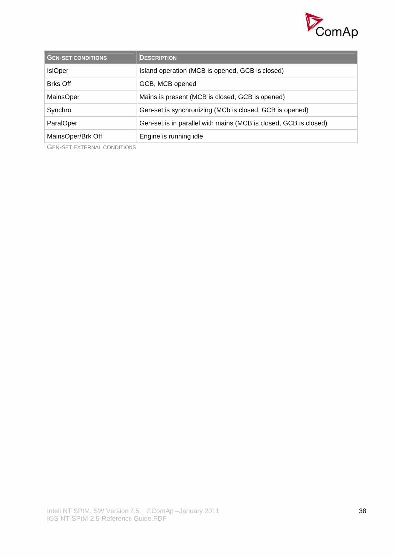
GEN-SET CONDITIONS DESCRIPTION
IslOper Island operation (MCB is opened, GCB is closed)
Brks Off GCB, MCB opened
MainsOper Mains is present (MCB is closed, GCB is opened)
Synchro Gen-set is synchronizing (MCb is closed, GCB is opened)
ParalOper Gen-set is in parallel with mains (MCB is closed, GCB is closed)
MainsOper/Brk Off Engine is running idle GEN-SET EXTERNAL CONDITIONS
Inteli NT SPtM, SW Version 2.5, ©ComAp –January 2011 IGS-NT-SPtM-2.5-Reference Guide.PDF
39
Inputs and Outputs
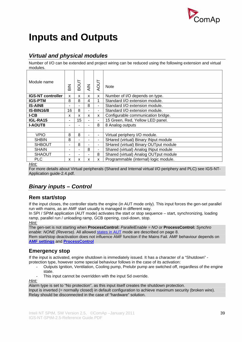
Virtual and physical modules Number of I/O can be extended and project wiring can be reduced using the following extension and virtual modules. Module name
BIN
BO
UT
AIN
AO
UT
Note
IGS-NT controller x x x x Number of I/O depends on type. IGS-PTM 8 8 4 1 Standard I/O extension module. IS-AIN8 - - 8 - Standard I/O extension module. IS-BIN16/8 16 8 - - Standard I/O extension module. I-CB x x x x Configurable communication bridge. IGL-RA15 - 15 - - 15 Green, Red, Yellow LED panel. I-AOUT8 - - - 8 8 Analog outputs VPIO 8 8 - - Virtual periphery I/O module. SHBIN 8 - - - SHared (virtual) Binary INput module SHBOUT - 8 - - SHared (virtual) Binary OUTput module SHAIN - - 8 - Shared (virtual) Analog INput module SHAOUT - - - 8 Shared (virtual) Analog OUTput module PLC x x x x Programmable (internal) logic module. Hint: For more details about Virtual peripherals (Shared and Internal virtual I/O periphery and PLC) see IGS-NT-Application guide-2.4.pdf.
Binary inputs – Control
Rem start/stop If the input closes, the controller starts the engine (in AUT mode only). This input forces the gen-set parallel run with mains, as an AMF start usually is managed in different way. In SPI / SPtM application (AUT mode) activates the start or stop sequence – start, synchronizing, loading ramp, parallel run / unloading ramp, GCB opening, cool-down, stop. Hint: The gen-set is not starting when ProcessControl: ParallelEnable = NO or ProcessControl: Synchro enable: NONE (Reverse). All allowed states in AUT mode are described on page 8. Rem start/stop deactivation does not influence AMF function if the Mains Fail. AMF behaviour depends on AMF settings and ProcessControl
Emergency stop If the input is activated, engine shutdown is immediately issued. It has a character of a “Shutdown” -protection type, however some special behaviour follows in the case of its activation:
- Outputs Ignition, Ventilation, Cooling pump, Prelubr pump are switched off, regardless of the engine state.
- This input cannot be overridden with the input Sd override. Hint: Alarm type is set to “No protection”, as this input itself creates the shutdown protection. Input is inverted (= normally closed) in default configuration to achieve maximum security (broken wire). Relay should be disconnected in the case of “hardware” solution.
Inteli NT SPtM, SW Version 2.5, ©ComAp –January 2011 IGS-NT-SPtM-2.5-Reference Guide.PDF
40
Nominal speed When this input is activate, the controller state is forced from Idle state to Running state, during the start of the engine. This action is allowed only 5 seconds after the starter is disangaged ( = 5 seconds after beginning of Idle time). This 5 seconds delay is caused by the fact, that 5 seconds after starter disangagement, the Underspeed protection is not evaluated ( possible RPM swing). So even if the LBI: Nominal speed is active all the time, the controller will be forced into the Running state 5 seconds after starter is disangaged. This binary input is not working in Cooling state, the controller is not forced back to the running state neither when Cooling speed = Nominal nor Idle. Hint: Use this input if you want to shorten the start-up procedure in an AMF situation.
PrestartBypass If the input is closed, the controller bypasses the Prestart time and activates the Starter output immediately. Hint: Use this input to bypass the pre-glow / prelubrication time in the case that the engine has run a short time before.
Oil press Behavior for Inverted = Open to activate configuration: Binary input must be closed when engine is not running and opened when it is running. "Sd Oil press B" is activated when input is opened on not running engine (“still engine” condition) or when stays closed for Engine protect: RunOnlyBlkDel1 after engine start. "Sd Oil press B" protection is not active when input is not configured.
Sd override If the input is closed, all 2nd level protections are disabled to allow engine run in an emergency situation, e.g. sprinkler devices power supply. All protections are shown in Alarmlist and recorded into History, but the controller doesn’t stop the engine because of them. If the input is deactivated and some protections are still active or not yet reset, the controller starts to take these protections into account and consequently stops the engine. Hint: All 2nd level protections are locked out, except of these:
- Emergency stop - Overspeed - Underspeed (only if Fuel solenoid = GAS ENGINE)
Emerg. manual This input is designed to allow the gen-set to be controlled externally, not by the controller. This feature is especially designed for marine gen-sets, which are supposed to be started manually as the controller has no power supply before the gen-set is started. It may be also useful in case of testing the gen-set or in case of a failure, which does not allow the gen-set to be controlled by the controller, but the gen-set itself is stays operational. The controller behaves following way:
- Shows the text EmergMan in the engine status on the main screen. - Stops all functions regarding the gen-set control, deactivates all outputs related to it. - Stop Fail alarm is not beeing evaluated and stop solenoid is not activated if nonzero speed is detected. - Voltage, current, power and other electric measurements are active. - When the input is deactivated, the controller takes control over the gen-set according to the situation in which the gen-set was in the moment of deactivation. I.e. the gen-set remains running loaded if it was running and GCB was closed in the moment the input was deactivated.
Hint: For successful recovery from a running state when the input is deactivated it is recommended to use pulse-type control outputs instead of continous-type. E.g. Stop Solenoid for fuel supply control and GCB ON coil, GCB OFF coil for breaker control.

Inteli NT SPtM, SW Version 2.5, ©ComAp –January 2011 IGS-NT-SPtM-2.5-Reference Guide.PDF
41
RunIndication 1
RunIndication 2
RunIndication 3 Any of three binary inputs can be used for engine running indication e.g. via Oil pressure contact. Active Running indication blocks engine start (to avoid starter damage).
AccessLock int If the input is closed, no setpoints can be adjusted from the controller front panel. Hint: For IS-NT and IG-NT, this input is controlling the display #1, which is supposed to be attached to or close to the main module. As the controller mode (OFF-MAN-AUT-TEST) is one of the setpoints, not even that can be changed. The START, STOP, FAULT RESET and other control buttons are disabled as well. For remote displays 2 and 3 use AccessLock D#2 or AccessLock D#3.
AccessLock D#2 If the input is closed, no setpoints can be adjusted and no commands can be issued from IG/IS-Display #2. Hint: It is not possible to start and stop the gen-set, change controller mode or control breaker.
AccessLock D#3 If the input is closed, no setpoints can be adjusted and no commands can be issued from IS-Display #3. Hint: It is not possible to start and stop the gen-set, change controller mode or control breaker.
AccessLock ext If the input is closed, no setpoints can be adjusted and no commands can be issued from any external terminal = via direct/modem/internet connection to the controller. Hint: Use these inputs to lock out the selected terminals for setpoint changes and commands (statistic, password and access code change). Such a terminal can only be used for monitoring.
Remote OFF Active binary input forces the controller mode to OFF. When opened the controller is switched to previous mode. If the engine is running, the active input has no effect. The controller switches to OFF mode only after the engine has been stopped. Hint: Use this input to block the engine start during service. The control unit recovers to the previous mode if BI Remote OFF opened.
Remote MAN Active binary input forces the controller mode to MAN. Hint: The control unit recovers to the previous mode if BI Remote MAN opened.
Remote AUT Active binary input forces the controller mode to AUT. Hint: Use this input to switch the controller to automatic operation, e.g. using the external key switch. The control unit recovers to the previous mode if BI Remote AUT opened.

Inteli NT SPtM, SW Version 2.5, ©ComAp –January 2011 IGS-NT-SPtM-2.5-Reference Guide.PDF
42
Remote TEST Active binary input forces the controller mode to TEST. Hint: Use this input for periodic engine tests (in combination with Timer module). Affects the behavior in TEST mode. The control unit is switched to TEST mode. Behaviour in TEST mode depends on settings AMF settings: ReturnTo mains and BI:Remote TEST
Force block 1
Force block 2
Force block 3 Three binary inputs for user-specific blocking of programmable protections. If the particular input is active, all the protections with the corresponding “Force block X” block type are blocked.
StartButton Binary input has the same function as Start button on the controller front panel. It is only active in MAN mode and when setpoint Basic settings -> Local Button is set to EXTBUTTONS or BOTH.
StopButton Binary input has the same function as Stop button on the controller front panel. It is only active in MAN mode and when setpoint Basic settings -> Local Button is set to EXTBUTTONS or BOTH.
FaultResButton Binary input has the same function as Fault reset button on the controller front panel. To enable this function, set the setpoint Basic settings -> Local Button to EXTBUTTONS or BOTH.
HornResButton Binary input has the same function as Horn reset button on the controller front panel.
MCBButton Binary input has the same function as MCB button on the controller front panel. It is active in MAN and TEST modes only. In TEST mode in some special cases only (see description TEST mode).
GCBButton Binary input has the same function as GCB button on the controller front panel. It is active in MAN and TEST modes only. In TEST mode in some special cases only (see description TEST mode). Hint: All Binary inputs, which simulate controller front panel buttons, are edge (no level) sensitive, and they react on the rising edge only. Minimal input pulse duration is 0,2 seconds.
ManualLdRecon The rising edge on this input switches the controller to the lower Load Shedding stage when AutoLd recon = DISABLED and the load is under Ld recon level.
Test on load Affects the behavior in TEST mode. The control unit is switched to TEST mode. Hint: Behaviour in TEST mode depends on settings AMF settings: ReturnTo mains.
GCB disable The input blocks the GCB closing, even if all other conditions (e.g. during synchronizing) for its closing are fulfilled. Valid in all modes. Hint:
Inteli NT SPtM, SW Version 2.5, ©ComAp –January 2011 IGS-NT-SPtM-2.5-Reference Guide.PDF
43
If you want to lock out the GCB (or MCB) closing during synchronizing loop test, set Phase window = 0. This allows the control loop to be tested while actual GCB (or MCB) closing is blocked. Conditions for closing:
1) voltage only on generator side of GCB (or MCB) 2) voltage on both sides of GCB (or MCB) and all synchronizing conditions fulfilled.
GCB disable do not open closed GCB. GCB disable only blocks the GCB closing.
MCB disable The input blocks MCB closing, even if all other conditions (e.g. during synchronizing) for its closing are fulfilled. Valid in all modes. Hint: If you want to lock out the GCB (or MCB) closing during synchronizing loop test, set Sync/Load ctrl: Phase window = 0. This allows the control loop to be tested while actual GCB (or MCB) closing is blocked. Conditions for closing:
1) voltage only on generator side of GCB (or MCB) 2) voltage on both sides of GCB (or MCB) and all synchronizing conditions fulfilled.
Alt brightness Active binary input switches controller display backlight to the alternative setting. Alternative intensity of the backlight can be set independently using the controller panel buttons. Hint: Input available in IG-NT/EE and modifications only. For IG-Display and IS-Display modules, this binary input is located in the Power connector and it’s function is fixed (not configurable).
IssueActCallC1
IssueActCallC2
IssueActCallC3 Rising edge on these binary inputs forces an active call to be issued via the corresponding channel. Hint: Can be used to send e.g. SMS in the case of a mains failure to report that the engine has successfully started (linked from the output Gen params OK) and later on to report that the engine has stopped again (linked from the inverted output Fuel solenoid).
ECUComFailBlck The input blocks the issuing of the alarm in case of ECU communication failure.
Startblocking The input blocks the engine start. If active, NotReady state is shown on the controller screen and a message appears in the Alarmlist. As soon as input is deactivated, engine start is enabled again. Hint: Use this input for cooperation with external supervisory device, such as PLC. It can prevent the engine to be started because of some reasons not known to the controller.
ECU StoppedEng Engine stop was activated in ECU, not from controller. The controller reflects this situation and also goes to Stop to avoid an Underspeed alarm (and record in the Alarm list).
CtrlHBeat sens This input is used at a redundant controller to sense the "heart beat" from the main controller. The input is to be connected to the output CtrlHeartBeat of the main controller. If the redundant controller does not sense the heart beat from the main one, it will activate the binary output CtrlHBeat FD, which has to be wired such a way, that it disconnects the dead main controller from the genset, connects the redundant controller instead and activates it
Inteli NT SPtM, SW Version 2.5, ©ComAp –January 2011 IGS-NT-SPtM-2.5-Reference Guide.PDF
44
Force value 1 …16 If any of the particular 16 input s is active, the Force value function on that corresponding channel gets active, forcing an alternative value to the selected setpoint.
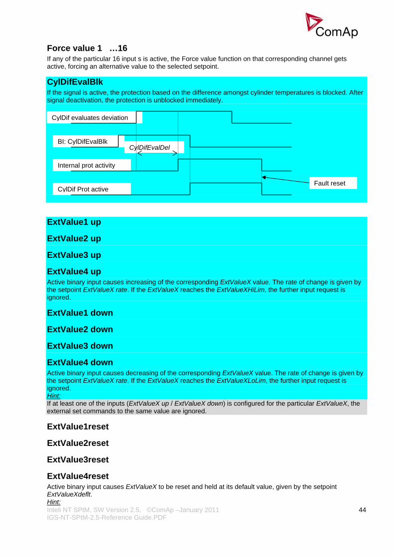
CylDifEvalBlk If the signal is active, the protection based on the difference amongst cylinder temperatures is blocked. After signal deactivation, the protection is unblocked immediately.
CylDif evaluates deviation
ExtValue1 up
ExtValue2 up
ExtValue3 up
ExtValue4 up Active binary input causes increasing of the corresponding ExtValueX value. The rate of change is given by the setpoint ExtValueX rate. If the ExtValueX reaches the ExtValueXHiLim, the further input request is ignored.
ExtValue1 down
ExtValue2 down
ExtValue3 down
ExtValue4 down Active binary input causes decreasing of the corresponding ExtValueX value. The rate of change is given by the setpoint ExtValueX rate. If the ExtValueX reaches the ExtValueXLoLim, the further input request is ignored. Hint: If at least one of the inputs (ExtValueX up / ExtValueX down) is configured for the particular ExtValueX, the external set commands to the same value are ignored.
ExtValue1reset
ExtValue2reset
ExtValue3reset
ExtValue4reset Active binary input causes ExtValueX to be reset and held at its default value, given by the setpoint ExtValueXdeflt. Hint:
BI: CylDifEvalBlk CylDifEvalDel
Internal prot activity
CylDif Prot active Fault reset

Inteli NT SPtM, SW Version 2.5, ©ComAp –January 2011 IGS-NT-SPtM-2.5-Reference Guide.PDF
45
These inputs, if configured, do not block the external set commands (in contrast to ExtValueX up / ExtValueX down inputs). However, if the reset input is activated, the corresponding ExtValueX is reset to its default (ExtValueXdeflt) value. This default value is kept in ExtValueX until the reset input is deactivated, and the external set commands received meanwhile are ignored.
Pulse Counter Hint: Pulse width (both high/low levels) must be at least 100 ms in order to be correctly sensed! Conversion ratio can be selected using the setpoints ConvCoefPulse. The converted values are visible in statistics – values PulseCounter. These values can be reset using Statistics window in InteliMonitor. The minimum ratio beteen log. 1 and log. 0 has to be 1:1 This Binary input is not IS-NT archives.
PulseCounter 1
PulseCounter 2
PulseCounter 3
PulseCounter 4 The inputs are linked with corresponding counters, which integrate the pulses sensed at these inputs. Each rising edge of the signal at input increases the internal counter value. Hint: Pulse width (both high/low levels) must be at least 100 ms in order to be correctly sensed! Conversion ratio can be selected using the setpoints ConvCoefPulseX. The converted values are visible in statistics – values PulseCounter X. These values can be reset using Statistics window in InteliMonitor. The minimum ratio beteen log. 1 and log. 0 has to be 1:1
Timer block 1
Timer block 2
Timer block 3
Timer block 4
Timer block 5
Timer block 6
Timer block 7
Timer block 8
Timer block 9
Timer block 10
Timer block 11
Timer block 12
Timer block 13
Timer block 14
Timer block 15
Inteli NT SPtM, SW Version 2.5, ©ComAp –January 2011 IGS-NT-SPtM-2.5-Reference Guide.PDF
46
Timer block 16 Blocking inputs for particular timer module channels. The input can lock out its assigned channel – if this input is active, the channel won’t activate its output (Timer active X) to e.g. start the engine.
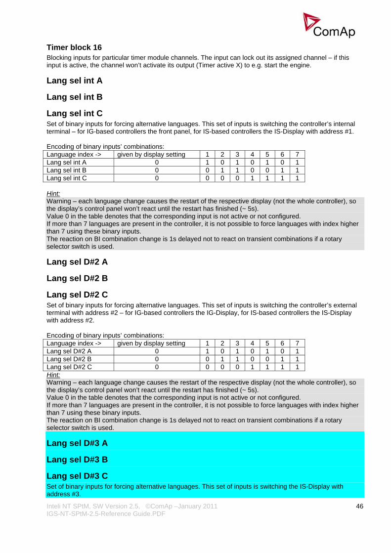
Lang sel int A
Lang sel int B
Lang sel int C Set of binary inputs for forcing alternative languages. This set of inputs is switching the controller’s internal terminal – for IG-based controllers the front panel, for IS-based controllers the IS-Display with address #1. Encoding of binary inputs’ combinations: Language index -> given by display setting 1 2 3 4 5 6 7 Lang sel int A 0 1 0 1 0 1 0 1 Lang sel int B 0 0 1 1 0 0 1 1 Lang sel int C 0 0 0 0 1 1 1 1 Hint: Warning – each language change causes the restart of the respective display (not the whole controller), so the display’s control panel won’t react until the restart has finished (~ 5s). Value 0 in the table denotes that the corresponding input is not active or not configured. If more than 7 languages are present in the controller, it is not possible to force languages with index higher than 7 using these binary inputs. The reaction on BI combination change is 1s delayed not to react on transient combinations if a rotary selector switch is used.
Lang sel D#2 A
Lang sel D#2 B
Lang sel D#2 C Set of binary inputs for forcing alternative languages. This set of inputs is switching the controller’s external terminal with address #2 – for IG-based controllers the IG-Display, for IS-based controllers the IS-Display with address #2. Encoding of binary inputs’ combinations: Language index -> given by display setting 1 2 3 4 5 6 7 Lang sel D#2 A 0 1 0 1 0 1 0 1 Lang sel D#2 B 0 0 1 1 0 0 1 1 Lang sel D#2 C 0 0 0 0 1 1 1 1 Hint: Warning – each language change causes the restart of the respective display (not the whole controller), so the display’s control panel won’t react until the restart has finished (~ 5s). Value 0 in the table denotes that the corresponding input is not active or not configured. If more than 7 languages are present in the controller, it is not possible to force languages with index higher than 7 using these binary inputs. The reaction on BI combination change is 1s delayed not to react on transient combinations if a rotary selector switch is used.
Lang sel D#3 A
Lang sel D#3 B
Lang sel D#3 C Set of binary inputs for forcing alternative languages. This set of inputs is switching the IS-Display with address #3.

Inteli NT SPtM, SW Version 2.5, ©ComAp –January 2011 IGS-NT-SPtM-2.5-Reference Guide.PDF
47
Encoding of binary inputs’ combinations: Language index -> given by display setting 1 2 3 4 5 6 7 Lang sel D#3 A 0 1 0 1 0 1 0 1 Lang sel D#3 B 0 0 1 1 0 0 1 1 Lang sel D#3 C 0 0 0 0 1 1 1 1 Hint: Warning – each language change causes the restart of the respective display (not the whole controller), so the display’s control panel won’t react until the restart has finished (~ 5s). Value 0 in the table denotes that the corresponding input is not active or not configured. If more than 7 languages are present in the controller, it is not possible to force languages with index higher than 7 using these binary inputs. The reaction on BI combination change is 1s delayed not to react on transient combinations if a rotary selector switch is used.
ECUcomFailBlck Active input enables to block indication of ECU communication fail e.g. in the case the ECU is switched off.
Binary inputs – Status information
GCB feedback Generator Circuit Breaker positive feedback input (closed if GCB is closed). This is a primary source for the controller about the status of the GCB. Hint: GCB feedback has to be configured to a physical input of controller. Do not configure any breakers feedback to the peripheral modules, it could caused problems due to time delay..
GCB fdb neg Generator Circuit Breaker negative feedback input (closed if GCB is open). Additional signal, can be used if both positive and negative feedback signals are available from the breaker. Hint: If both feedbacks are used and there is a mismatch between these signals, longer than 500 ms, a GCB fail alarm is activated.
MCB feedback Mains Circuit Breaker positive feedback input (closed if MCB is closed). This is a primary source for the controller about the status of the MCB. Hint: The controller decides based on this signal whether the gen-set is running in mains parallel or island operation.
MCB fdb neg Mains Circuit Breaker negative feedback input (closed if MCB is open). Additional signal, can be used if both positive and negative feedback signals are available from the breaker. Hint: If both feedbacks are used and there is a mismatch between these signals, longer than 500 ms, a MCB fail alarm is activated.
NeutralCB fdb Use this input to detect, whether the Neutral circuit breaker is open or closed. See also setpoint Neutral cont and binary output Neutral CB C/O.

Inteli NT SPtM, SW Version 2.5, ©ComAp –January 2011 IGS-NT-SPtM-2.5-Reference Guide.PDF
48
Binary outputs
Starter The output is intended to energize the starter motor during start sequence. The output opens if the Starting RPM level is reached or maximum time of cranking is exceeded. Hint: If setpoint Fuel solenoid = GAS ENGINE, the Starter output is active during Preventilation and Ventilation states as well to clean the engine off the unburned gas.
Fuel solenoid The output is intended to control the engine fuel valve. The setpoint Engine params: Fuel solenoid selects the output behaviour – DIESEL or GAS ENGINE.
Stop solenoid The output closes to activate the stop valve which interrupts the fuel input to the engine. The output is always closed until the engine reaches 0 RPM and other “engine running” conditions disappear as well + additional 10s. The minimum time of activation is given by the Stop time setpoint, so even if all “engine running” conditions would disappear before, the Stop solenoid stays closed for that time. Hint: The output also closes if the engine begins to rotate spontaneously. It stays closed until “still engine” condition is achieved + additional 10s. Intended only for diesel engines, especially marine ones.
Stop pulse 1s pulse for engine stop command, intended for ECU connection.
Prestart The output closes prior to the engine start (time defined by Prestart setpoint) and opens when Starter output opens the last time during starting sequence. During repeated crank attempts the output is constantly closed. The output can be used for pre-glow, pre-heat or prelubrication.
Ignition Intended to activate the ignition unit of gas engines. The output closes immediately as “engine running” condition is detected and opens after the engine stop (“still engine” condition). The function is independent on other conditions, i.e. always if “engine running” is detected, the output activates. The output opens immediately when BI Emergency stop gets active. Hint: In case of repeated start: a) the output is switched on when RPM = 30 (it is fixed value) b) the output is switched off during Crank pause, but not until RPM fell down to 0 c) the output is switched off by STOP command when RPM=0
Ventilation Intended for the engine ventilator control. The output closes together with Prestart output and opens after the engine stop (“still engine” condition). The output opens immediately when BI Emergency stop gets active or in OFF mode. Hint: The output gets active also when genset is spontaneously (not required) cranking.
Idle/Nominal The output closes with transition from Starting (Idle) to Running state. It opens either with transition to Cooling state (if Cooling speed = IDLE), or after the command to stop the engine (if Cooling speed = NOMINAL). The closed output means that Nominal RPM are requested. Hint:

Inteli NT SPtM, SW Version 2.5, ©ComAp –January 2011 IGS-NT-SPtM-2.5-Reference Guide.PDF
49
Connect this output to the speed governor to switch the requested speed: opened = IDLE RPM, closed=Nominal RPM.
Cooling pump The output closes when gen-set starts (“engine started” condition) and opens AfterCoolTime delayed after the engine stop (“still engine” condition). The output opens immediately when BI Emergency stop gets active or in OFF mode. Hint: When after cooling time is active and BI Emergency stop is deactivated, cooling pump becomes active.
Prelubr pump If engine is not running, the output closes with period Prelubr pause for Prelubr time. The output opens immediately when BI Emergency stop gets active or in OFF mode.
Not lubricated Output indicates the lubrication cycle (PrelubrTime) is not finished after controller Switch-on or return from OFF mode or deactivation of Emergency stop signal.
Binary outputs – Breaker control
GCB close/open The output controls the generator circuit breaker. It is intended for contactors – provides a continual active signal if GCB should be closed.
GCB ON coil The pulse output for GCB closing. If GCB synchronizing is enabled, the pulse length is 2s, if not, pulse length is 5s. Hint: ON coil can only be closed if UV coil is already active for at least 1s and MinStab time has elapsed.
GCB OFF coil The pulse output for GCB opening. If GCB synchronizing is enabled, the pulse length is 2s, if not, pulse length is 5s.
GCB UV coil GCB undervoltage coil. Output is closed if generator values are within limits and GCB is ready to be closed. It is opened if GCB should be open, and then closed again if generator electric values are in limits. If GCB synchronizing is enabled, the opening pulse length is 2s, if not, pulse length is 5s. Hint: UV coil automatically opens and OFF coil closes if GCB is closed spontaneously, not from controller’s activity. This state lasts until the GCB status has been deactivated. The only exception is during synchronization state, as an external device is allowed to close the GCB.

Inteli NT SPtM, SW Version 2.5, ©ComAp –January 2011 IGS-NT-SPtM-2.5-Reference Guide.PDF
50
GCB status Indicates breaker state expected by controller (based on gen-set state, controller commands and breaker feedback). Can be used for external indication of breaker status according to controller’s information.
MCB status Indicates breaker state expected by controller (based on gen-set state, controller commands and breaker feedback). Can be used for external indication of breaker status according to controller’s information.
MCB close/open The output controls the mains circuit breaker. It is intended for contactors – provides a continual active signal if MCB should be closed. Hint: Use binary output inversion (in GenConfig during configuration) to achieve that closed output = breaker opened.
MCB ON coil The pulse output for MCB closing. If MCB synchronizing is enabled, the pulse length is 2s, if not, pulse length is 5s. Hint: ON coil can only be closed if UV coil is already active for at least 1s.
MCB OFF coil The pulse output for MCB opening. If MCB synchronizing is enabled, the pulse length is 2s, if not, pulse length is 5s.
MCB UV coil MCB undervoltage coil. Output is closed if mains values are within limits and MCB is ready to be closed. It is opened if MCB should be open, and then closed again if mains electric values are in limits. If MCB synchronizing is enabled, the opening pulse length is 2s, if not, pulse length is 5s.
Neutral CB C/O Neutral circuit breaker close /open output controls the generator Neutral circuit breaker. It is intended for contactors – provides a continual active signal if NCB should be closed. See also setpoint Neutral cont.
LdShed stage 1
LdShed stage 2
LdShed stage 3 Load shedding outputs for partial load switching.
Binary outputs – Control loops
AVR up
AVR dn Binary outputs for Volt / PF control by motorized or electronic potentiometer.
Speed up
Speed dn Binary outputs for Synchronizing and Load control. Outputs can be used instead of analog Speed governor output for older engine types. Minimum pulse duration is 0,15 sec. Maximum pulse duration is 10,0 sec.
Inteli NT SPtM, SW Version 2.5, ©ComAp –January 2011 IGS-NT-SPtM-2.5-Reference Guide.PDF
51
Binary outputs UP nad DOWN of a PID regulator produce pulses, whose length correspond to derivation of the analog output (further AOUT) of the same regulator. In other words:
1. If there is no change of the AOUT, no pulses are produced 2. If the AOUT is increasing, pulses are generated on the UP output. Pulse length depends on speed of
the increase. 3. If the AOUT is decreasing, pulses are generated on the DOWN output. Pulse length depends on
speed of the decrease. 4. Long pulses on the same output can merge 5. If the calculated pulse in each particular cycle is too short, it is not copied to the output, but is only
buffered. When the buffered pulse exceeds minimal pulse length, pulse is generated to appropriate output.
The pulses are generated even if the analog regulator output is already at limit value. As for speed and voltage regulation, this kind of regulation is good for droop-based systems. At isochronous system, it can cause stability problems, because it is slower. Hint: When Speed governor output stays near to the limit value (SpeedGovLowLim+0,2 V or SpeedGovHiLim-0,2 V) for more than 2 sec, the “Wrn SpdRegLim” message is displayed in the Alarm list and recorded to History. When AVRi output stays on <2% or >98% for more than 2 sec, the “Wrn VoltRegLim” is displayed in the Alarm list and recorded to History. Corresponding warning is blocked when Binary outputs Speed Up, Speed Dn or AVR up, AVR dn are configured to a physical BO or VPIO. It is not recommended to process these signals via the internal PLC, as the precise signal timing would be distorted.
RemoteControl1
RemoteControl2
RemoteControl3
RemoteControl4
RemoteControl5
RemoteControl6
RemoteControl7
RemoteControl8 These outputs are controlled remotely from InteliMonitor or other tool. The user selects the requested state of these outputs via the buttons in this program. Hint: Outputs can be used to switch on/off some auxiliary devices in the control panel.
Binary outputs – Status information
Ready for load The output closes when the engine is running, no 2nd level protection is active and the GCB is already closed or is able to be closed (i.e. all generator parameters are within limits).
Stand-by ready The output closes when the engine is ready for stand-by: SEM / AUT mode, no 2nd level protection active.

Inteli NT SPtM, SW Version 2.5, ©ComAp –January 2011 IGS-NT-SPtM-2.5-Reference Guide.PDF
52
Gen-set active The output closes together with Prestart output and opens together with achieving “still engine” condition after the stop command. If the start sequence finishes with Start fail, the output opens after the last unsuccessful start attempt. Hint: The output also closes if the engine begins to rotate spontaneously. It stays closed until “still engine” condition is achieved.
Operational The output is closed when no protection is active and the gen-set is ready for operation or is currently in operation.
Ready The output is closed, if following conditions are fulfilled: - Gen-set is not running and - No 2nd level protection is active (or not yet reset) - The controller has no “engine running” indication from any source - The controller is not in OFF mode
Not ready The output is closed, if following conditions are fulfilled: - The controller in OFF mode or - Any 2nd level alarm is active or not yet reset
CrankProcedure The output closes together with the first Starter activation and opens with the last Starter deactivation (either “engine running” state achieved, or Start fail). During crank pauses, the output stays closed.
Cranking Indication of cranking procedure.
Starting The output closes together with Prestart output and opens with transition from Idle to Running state or with Start fail output activation. During crank pauses, the output stays closed.
Idle run The output closes if “engine started” condition is detected after start and opens with Starting to Running transition. Hint The Idle run is deactivated when stop command is activated or 2nd level protection gets active.
Running The output closes with transition from Starting to Running state. It opens with transition to Cooling state or if any 2nd level protection gets active. It stays closed if the engine is loaded.
ForwardSynchro The output is closed during forward synchronizing and opens when GCB status gets active (= GCB was closed). The output can be used for external synchronizing module control.
ReverseSynchro The output is closed during reverse synchronizing (with load) and opens when MCB status gets active (= MCB was closed). The output can be used for external synchronizing module control.

Inteli NT SPtM, SW Version 2.5, ©ComAp –January 2011 IGS-NT-SPtM-2.5-Reference Guide.PDF
53
Warming The output is closed during warming procedure – the gen-set power is kept at Warming load level in this period.
Soft load The output is closed during gen-set soft loading state – the gen-set power is ramping up, i.e. since GCB was closed until the end of the ramp.
Loaded The output is closed when gen-set is loaded – GCB is closed and no load ramp is active.
Soft unload The output is closed during gen-set soft unloading state – gen-set power is ramping down.
Cooling The output closes during engine Cooling state, i.e. from GCB opening to stop command.
Stopping The output closes after the command to stop has been issued. It opens if “still engine” conditions are fulfilled. The output also closes if the engine begins to rotate spontaneously during Stop Time. It stays closed until “still engine” condition is achieved. Hint: Stop command is activated after cooling time elapsed.
Off mode The output is closed, if OFF mode is selected.
Man mode The output is closed, if MAN mode is selected.
Sem mode The output is closed, if SEM mode is selected.
Aut mode The output is closed, if AUT mode is selected.
Test mode The output is closed, if TEST mode is selected. These outputs follow the actual controller mode.
Gen params OK The output is copy of generator status LED on controller front panel. The output is closed if gen-set is running and all generator electric values are in limits and no 2nd level alarm is active (when only 1st level alarm is active, the output is closed). Hint: Use this output for switching on of auxiliary device driven from generator voltage independently on the GCB status.
MainsParams OK The output is copy of mains status LED on controller front panel. The output is closed if mains electric values are in limits.
In synchronism The output closes during synchronizing if all matching conditions are fulfilled. It opens if corresponding breaker is closed (xCB status output get active).
Inteli NT SPtM, SW Version 2.5, ©ComAp –January 2011 IGS-NT-SPtM-2.5-Reference Guide.PDF
54
Hint: Synchronizing matching conditions:
- Slip frequency < 0,25 Hz - Gen to Mains/Bus voltage phase shift within Sync/Load ctrl:Phase window - Gen and Mains/Bus voltages within Sync/Load ctrl:Voltage window - Sync/Load ctrl:Dwell time elapsed
StartButnEcho
StopButnEcho
FltResButnEcho
HrnResButnEcho
GCBButnEcho
MCBButnEcho These outputs are active for 1s if the corresponding button is pressed or binary input gets active or remote command is issued (from PC software, SMS, ...). Hint: This function is valid only when command is allowed. (Pulse is not generated in OFF mode and during start procedure). All functions related to front panel buttons depends on setpoint settings Basic settings -> Local Button
CtrlHeartBeat The output flashes at 500ms / 500ms rate in controller healthy state. It stops flashing when the unit reset occurs and the new controller start-up fails (signalizes watchdog reset).
Bin selector 1-4 Any of the four outputs is active according to the corresponding setpoints Bin selector X. These are used for particular ECU settings.
Logical 0 Constant value that can be configured to any output.
Logical 1 Constant value that can be configured to any output.
WrongPhSeq Binary output WrongPhSeq is active when at least one of following conditions is fulfilled: Generator, (Mains, Bus) phase is inverted or wrong generator (mains, bus) phase sequence or opposed generator phase sequence is detected.
TimerAct 1-4
TimerAct 5-8
TimerAct 9-12
TimerAct 13-16 These outputs are active if at least one of their assigned timer module channels gets active. Timer module channels are organized into groups of four.

Inteli NT SPtM, SW Version 2.5, ©ComAp –January 2011 IGS-NT-SPtM-2.5-Reference Guide.PDF
55
TimerActiveCom This output is a logical OR (Com = Common) of the outputs TimerAct 1-4, 5-8, 9-12, 13-16. It gets active if any timer module channel is active.
kWh pulse The pulse with 100 miliseconds width is generated after each kWh.
Binary outputs – Fixed protection outputs
Alarm The output closes if any alarm comes up. It opens if FAULT RESET is pressed. The output closes again if a new fault comes up.
Alarm flashing If any alarm comes up, the output starts periodic closing/opening with period 1s/1s. It opens and stays open if FAULT RESET is pressed.
Horn The output closes if any alarm comes up. It opens if FAULT RESET or HORN RESET is pressed or if Horn timeout has elapsed. The output closes again if a new fault comes up.
Horn flashing If any alarm comes up, the output starts periodic closing/opening with period 1s/1s. It opens and stays open if FAULT RESET or HORN RESET is pressed or if Horn timeout has elapsed.
Common Hst The output closes if any “History record”-protection type appears. The output opens after 1s.
Common MP The output closes if any “Mains protection”-protection type appears. The output opens, if no “Mains protection”-protection type is active. No FAULT RESET needed.
Common LoP The output closes if any “Low power”-protection type appears. The output opens, if no “Low power”-protection type is active. No FAULT RESET needed.
Common Al The output closes if any “Alarm only”-protection type appears. The output opens, if no “Alarm only”-protection type is active and FAULT RESET has been pressed.
Common Wrn The output closes if any “Warning”-protection type appears. The output opens, if no “Warning”-protection type is active and FAULT RESET has been pressed.
CommonActLev 1 The output is a logical OR of Common Al and Common Wrn outputs.
CommonAlLev 1 The output is active if at least one of the 1st level alarms (Al, Wrn) is active or not yet confirmed. Hint: See picture below with signal behaviour description. The same behaviour like for “Warning”-protection type would be for “Alarm only”.

Inteli NT SPtM, SW Version 2.5, ©ComAp –January 2011 IGS-NT-SPtM-2.5-Reference Guide.PDF
56
The same behaviour, but with signals CommonActLev 2 and CommonAlLev 2 would be for “BreakerOpen&Cool-down”, “Slow stop” and “Shutdown”-type alarms.
Common OfL The output closes if any “Off load”-protection type appears. The output opens, if no “Off load”-protection type is active. No FAULT RESET needed.
Common BOC The output closes if any “Breaker Open & Cool-down”-protection type appears. The output opens, if no “Breaker Open & Cool-down”-protection type is active and FAULT RESET has been pressed.
Common Stp The output closes if any “Slow stop”-protection type appears. The output opens, if no “Slow stop”-protection type is active and FAULT RESET has been pressed.
Common Sd The output closes if any “Shutdown”-protection type appears. The output opens, if no “Shutdown”-protection type is active and FAULT RESET has been pressed.
Common SdOvr Common output that gets active with 2s delay if any Shutdown override-type protection becomes active. If it is already active and another protection of that type becomes active, the output is deactivated for 2 seconds and then reactivated again to inform on this new alarm.

Inteli NT SPtM, SW Version 2.5, ©ComAp –January 2011 IGS-NT-SPtM-2.5-Reference Guide.PDF
57
CommonActLev 2 The output is a logical OR of Common BOC, Common Stp and Common Sd outputs.
CommonAlLev 2 The output is active if at least one of the 2nd level alarms (BOC, Stp, Sd) is active or not yet confirmed.
Common Fls The output closes if any “Fail sensor” protection type appears. The output opens, if no “Fail sensor”-protection type is active and FAULT RESET has been pressed.
T cyl differ Output closes when engine cylinder temperature difference warning is active.
Vgen <> The output closes if the generator over/under voltage protection becomes active. Alarm appears in the alarm list as an effect of this protection.
Vmains <> The output closes if the mains over/under voltage alarm activates.
VectorShiftTrp The output closes if the Vector shift protection gets active and the controller actually trips the selected breaker. The output stays closed for 3s, then opens again.
VectorShiftAct The output closes if the Vector shift protection gets active. It stays closed for 3s, then opens again. This output is activated regardless of the activity of the input Sd Override.
Overcurrent The output closes if the generator IDMT Overcurrent or Shortcurrent alarm activates. The output opens, if none of these alarms is active and FAULT RESET has been pressed.
ECU comm error Output closes if there is an error in the communication with ECU. It doesn’t matter how the ECU is connected – J1939 link or RS232 line. The output doesn’t activate if binary output ECU PwrRelay is not active.
PeriphCommErr Output closes if there is an error in the communication with any peripheral unit (e.g. IS-AIN8, IGS-PTM, ...).

Inteli NT SPtM, SW Version 2.5, ©ComAp –January 2011 IGS-NT-SPtM-2.5-Reference Guide.PDF
58
CtrlHBeat FD This output is used at a redundant controller to disconnect the main controller from the gen-set, connect the redundant one instead and activate it. The output is closed: - If the input CtrlHBeat sens is configured onto any input terminal and the redundancy controller does not sense the "heart beat" signal from the main controller at that terminal. - If the redundant controller has not received two consequent messages from the main controller. The address of the main controller for the particular redundant one is selected by the the setpoint Watched Contr
CAN2 bus empty The output closes if the controller doesn’t “see” any other controllers on the CAN2 bus. The output activation can be blocked by setpoint Basic settings:CAN2emptDetect (So it should be DISABLED for single applications.)

Inteli NT SPtM, SW Version 2.5, ©ComAp –January 2011 IGS-NT-SPtM-2.5-Reference Guide.PDF
59
Binary outputs – Configurable prog. States
J1939 Indication of J1939 communication fail (configurable between No protection, Warning or Shutdown).
KWP2000 Indication of KWP2000 communication fail.
SHBinCfgErr Shared Binary module configuration error – i.e. more than one source was configured (is on the CAN2 bus).
SHAinCfgErr Shared Analog module configuration error – i.e. more than one source was configured (is on the CAN2 bus).
PLC State 1 .. 4 PLC state indication.
ECUDiagBlocked Output is active if any ECU is configured and when Basic setting: ECU diag = DISABLED. Hint: No ECU alarms are displayed on the controller screen.
WrongConfig Wrong controller configuration indication.
Reverse power Output is active when reverse power protection is active. Based on Gener protect: Reverse power and RevPower del.
Batt volt Indication of battery voltage protection based on Analog protection: Batt >V, Batt <V, Batt V del.
EarthFaultCurr Indication of Earth fault current protection based on Gener protect: EarthFaultCurr and EthFltCurr del.
Dongle incomp Incompatible (usually missing) dongle indication. Hint: The incompatible dongle is indicated e.g. in the case that: - power management is enabled (Pwr management: Pwr management <> DISABLED) and there is no dongle detected that enables this feature - load sharing function is enabled (Process control: #SysLdCtrl PtM = LDSHARING or (Process control: #SysLdCtrl PtM = BASE LOAD and logical binary output MCB STATUS = 0 at the same time and controller is not alone on the CAN bus)) and there is no dongle detected that enables this feature. Incompatible dongle is not indicated in case of MINT operated in single island operation (no other controllers detected on the CAN bus).
Emergency stop Activity of Emergency stop (from Binary input Emergency stop) indication. Hint: Any Binary output alarm indication that follows the corresponding internal state is activated with alarm and stays active until alarm reason disappears and the Fault reset (panel button or remote) is activated.

Inteli NT SPtM, SW Version 2.5, ©ComAp –January 2011 IGS-NT-SPtM-2.5-Reference Guide.PDF
60
WrnServiceT1+2 The output closes when ServiceTime1 or ServiceTime2 has reached zero. To reset the output (and the related WrnServiceT1+T2), it is necessary to set again a non-zero value to the corresponding setpoint.
WrnServiceT3+4 The output closes when ServiceTime3 or ServiceTime4 has reached zero. To reset the output (and the related WrnServiceT3+T4), it is necessary to set again a non-zero value to the corresponding setpoint.
Overspeed The output closes if the gen-set over speed alarm activates. The output opens, if alarm is no more active and FAULT RESET has been pressed.
Underspeed The output closes if the gen-set under speed alarm activates. Under speed limit is given by Starting RPM if the engine has already started (see Starting procedure description). The output opens, if alarm is no more active and FAULT RESET has been pressed.
Start fail The output closes if the gen-set start-up fails (= Cranking issued Crank attempts times and engine did not start). The output opens, if alarm is not active and FAULT RESET has been pressed.
Sd Stop fail Engine stop fail indication. Stop fail: engine does not reach “still engine” condition within Engine params: Stop time.
ChrgAlternFail Charger fail detection. Guaranteed level for signal Charging OK = 80% of supply voltage. Hint: D+ output current is limited to cca 300 mA.
Pickup fail Pickup fail indication. Pickup fail: lost of RPM signal in running state (“engine running” condition is active).
RTCbatteryFlat Output closes if the controllers real time clock battery drops under the reliable level. RTC battery is controlled once in 24h period.
Sd ExtBattFlat Output closes if the controller “wakes up” after a start attempt which caused the battery voltage to drop down and consequently the controller switch-off.
Stp GCB fail Output closes when GCB fail is detected and discordancy between feedback and command is detected for 500ms.
Wrn MCB fail Output closes when MCB fail is detected and discordancy between feedback and command is detected for 500ms.
Stp Sync fail The output is closed when the alarm Sync timeout is active. This behaviour occure when synchronization failed because of unfulfilled conditions.
Inteli NT SPtM, SW Version 2.5, ©ComAp –January 2011 IGS-NT-SPtM-2.5-Reference Guide.PDF
61
Manual Restore Output is activated when AMF settings: ReturnFromIsland is se to MANUAL and controller expect MCB press. Output is ddisactivade when MCB is pressed.
Wrn FuelTheft Outputs is activated If measured drop is higher then Fuel theft definition.
WrnRSync fail The output is closed when the alarm RevSyncTimeout is active.
WrnSpdRegLim Output indicates the controller Speed governor output is on limit. Hint: When Speed governor output stays near to the limit value (SpeedGovLowLim+0,2 V or SpeedGovHiLim-0,2 V) for more than 2 sec, the “Wrn SpdRegLim” message is displayed in the Alarm list and recorded to History.
WrnVoltRegLim Output indicates the controller AVRi output is on limit. Hint: When AVRi output stays on <2% or >98% for more than 2 sec, the “Wrn VoltRegLim” is displayed in the Alarm list and recorded to History.
WrnTstOnLdFail If Test on load function is activated (by closing corresponding BI), and there is not enough power to transfer all the load from mains to generator, the output closes after the Load ramp delay elapses. Together with that, the message “WrnTstOnLdFail” appears in Alarm list.
UnivState 1 … Univ state 15 Universal state 1 to Universal state 15 activity indication. Universal state can be used for additional protection configured to any internal value.
RPM Indication of RPM state.
Reserved These binary outputs are internally used and they are unsuitable for any physical or logical outputs and should not be configured.
Sd Oil press B Engine Shut-down is activated by Binary input “Oil press”.
ECU PwrRelay The output closes at the beginning of prestart and opens if the engine shall be stopped. This output can be used to indicate when the ECU should be powered up i.e. only while the engine is running. This output also influences evaluation of communication failure with ECU and related FLS alarms from analog inputs read from the ECU. If the output is configured (which means configured on physical binary output or VPIO output), the issuing of communication error is blocked during Prestart and Stopping procedure as shown in the picture.

Fuel solenoid deactivation
Beginning of Prestart
ECU PwrRelay
Inteli NT SPtM, SW Version 2.5, ©ComAp –January 2011 IGS-NT-SPtM-2.5-Reference Guide.PDF
62
Hint: The input must be configured on physical binary output or VPIO output. It is not enough to configure it as a PLC input for example.
Generator Voltage and Frequency alarms indication Basic settings: FixVoltProtSel = PHASE-NEUTRAL Binary output name Protection type Based on setpoint BOC L1 under BOC L2 under BOC L3 under
BreakerOpen & Cool-down
Gener protect: Gen <V BOC, Gen V del
BOC L1 over BOC L2 over BOC L3 over
BreakerOpen & Cool-down
Gener protect: Gen >V BOC, Gen V del
Sd L1 over Sd L2 over Sd L3 over
Shut-down
Gener protect: Gen >V SD Gener protect: Gen V del
Gen V L1-N Gen V L2-N Gen V L3-N
BreakerOpen & Cool-down Shut-down
Gener protect: Gen <V BOC Gener protect: Gen >V BOC Gener protect: Gen >V SD Gener protect: Gen V del
Basic settings: FixVoltProtSel = PHASE-PHASE Binary output name Protection type Based on setpoint BOC L12 under BOC L23 under BOC L31 under
BreakerOpen & Cool-down
Gener protect: Gen <V BOC Gener protect: Gen V del
BOC L12 over BOC L23 over BOC L31 over
BreakerOpen & Cool-down
Gener protect: Gen >V BOC Gener protect: Gen V del
Sd L12 over Sd L23 over Sd L31 over
Shut-down
Gener protect: Gen >V SD Gener protect: Gen V del
Gen V L1-L2 Gen V L2-L3 Gen V L3-L1
BreakerOpen & Cool-down Shut-down
Gener protect: Gen <V BOC Gener protect: Gen >V BOC Gener protect: Gen >V SD Gener protect: Gen V del
BOC fgen under Generator protect: Gen <f and Gen f del. BOC fgen over Generator protect: Gen >f and Gen f del. Gen freq
BreakerOpen & Cool-down Generator protect: Gen >f, Gen <f and Gen f del.
ECU communication failure alarm blocked
End of Prestart
Engine stopped
t

Inteli NT SPtM, SW Version 2.5, ©ComAp –January 2011 IGS-NT-SPtM-2.5-Reference Guide.PDF
63
Mains Voltage and Frequency alarms indication Binary output name Protection type Based on setpoint MP L1 under MP L2 under MP L3 under
BreakerOpen & Cool-down
Mains protect: Mains <V MP, Mains V del
MP L1 over MP L2 over MP L3 over
BreakerOpen & Cool-down
Mains protect: Mains >V MP, Mains V del
Binary output name Protection type Based on setpoint MP L12 under MP L23 under MP L31 under
Mains Protection
Mains protect: Mains <V MP and Mains V del.
MP L12 over MP L23 over MP L31 over
Mains Protection
Mains protect: Mains >V MP and Mains V del.
Mains V L1-L2 Mains V L2-L3 Mains V L3-L1
Mains Protection
Mains protect: Mains <V MP, Mains protect: Mains >V MP and Mains V del
MP fmns under MP fmns over Mains freq
Mains Protection
Mains protect: Mains <f, Mains protect: Mains >f, Mains protect: Mains f del.
Hint: L1-N, L2-N, L3-N alarm indications are active when Basic settings: FixVoltProtSel = PHASE-NEUTRAL. L1-L2, L2-L3, L3-L1 alarm indications are active when Basic settings: FixVoltProtSel = PHASE-PHASE.
OfL StartBlck Output indicates wrong setpoints setting that disables the engine start or taking the load. E.g. ProcessControl: Island enable; ParallelEnable; Synchro enable; MF start enable. Binary output name Protection type Based on setpoint BOC IDMT BreakerOpen & Cool-down Generator protect: 2Inom del. BOC ShortCurr BreakerOpen & Cool-down Generator protect: Ishort and Ishort del. BOC Overload BreakerOpen & Cool-down Generator protect: OverldStrtEval
Generator protect: 2POverldStEvDel BOC NCB fail BreakerOpen & Cool-down x
Analog inputs
LdCtrl:AnExBld External requested gen-set power value. • Configure LdCtrl:AnExtBld to selected analog input • Configure Analog input range • Adjust ProcessControl: Load ctrl PTM = ANEXT BASELOAD
LdCtrl:AnExI/E External requested mains import/export power value. • Configure input LdCtrl:AnExI/E to selected analog input • Configure Analog input range • Adjust ProcessControl: Load ctrl PtM to ANEXT IM/EX.
Inteli NT SPtM, SW Version 2.5, ©ComAp –January 2011 IGS-NT-SPtM-2.5-Reference Guide.PDF
64
PFCtrl:AnExBPF External requested gen-set power factor value. • Configure PFCtrl:AnExBPF to selected analog input • Configure Analog input range • Adjust ProcessControl: PF ctrl PTM = ANEXT BASEPF
PFCtrl:AnExI/E External requested mains import/export power factor value.
Example: In the following table corresponding current values on analog input and power factor values are noticed:
Ic [mA] Primary curve values
PF + Load Character Requested PF value
PF Converted curve value*
-20 0,60 L 0,60 -10 0,80 L 0,80 0 1,00 R 1,00 10 0,80 C 1,20 20 0,80 C 1,20
* Values 0.6 – 0.99 correspond to lagging PF, 1.01 – 1.20 correspond to leading PF. • Configure input PFCtrl:AnExI/E to selected analog input • Configure Analog input range • Adjust ProcessControl: PF ctrl PtM to ANEXT PF-IM/EX.
LdCtrl:I/E-Pm Mains import/export active power measured from an external transducer. • Configure LdCtrl:I/E-Pm to selected analog input • Configure Analog input range • Adjust ProcessControl: I/E-Pm meas = ANALOG INPUT
PFCtrl:I/E-Qm Mains import/export reactive power value from an external transducer. • Configure PFCtrl:I/E-Qm to selected analog input • Configure Analog input range • Adjust ProcessControl: I/E-Qm meas = ANALOG INPUT
LCD brightness Analog input for external LCD brightness setting (e.g. via potentiometer). Keyboard LCD brightness setting and binary input Alt brightness do not work when input is configured. Expected value is in the range 0 to 100%. Hint: In IG-NT/EE and modifications, this input controls the backlight of the built-in display. For optionally attached IG-Display module, this input has no meaning. In IS-NT and modifications, this input controls the backlight of the IS-Display with address #1. For optional displays with addresses #2 and #3, this input has no meaning.
PowerDerating1 Analog input for Power derating function, channel 1.
PowerDerating2 Analog input for Power derating function, channel 2. Hint: Power derating activation/deactivation is not written into the history log.

Inteli NT SPtM, SW Version 2.5, ©ComAp –January 2011 IGS-NT-SPtM-2.5-Reference Guide.PDF
65
LdCtrl:TByPwr Input to measure water temperature for temperature by generator power control.
RPM pick-up Logical Analog input for RPM receiving from various types of Engine Control Units (and optionally via I-CB).
Oil press Logical input for Oil pressure protection. Oil pressure is calculated into “running engine” condition when configured. Engine start is blocked if Oil pressure is higher than Starting POil setpoint setting.
Warming temp Input to measure engine temperature during warm-up procedure. See setpoints Engine params: Warming load, Warming temp, Max warm time.
Fuel level Input that has to be used when Fuel Theft function is used. It indicates fuel level state in the fuel tank.
T Cyl 1 - 32 32 inputs to measure Cylinder Temperatures. Configured cylinder temperatures are displayed on controller measurement screens as well as average cylinder temperature. Cylinder temperature protection is based on the difference against average temperature.
Cold Temp 1-4 In case there is a separate thermocouple sensor for measuring the “cold end” of cylinder temperatures evaluation, configure that sensor to this analogue function.
Analog outputs The IS-NT has one analog output available. Default setting of this output is the value of actual generator power in the range 0 to 20 mA. Hint: It is possible to configure any other value available in the configuration using GenConfig. If the output range 4 to 20 mA is needed, the limits for analog output should be set according to an example in the following table:
Requested power range Controller analog output setting 0 – 1000 kW Low limit: -250 kW
High limit: 1000 kW Low – High kW Low limit: Low - (High – Low)/4 kW
High limit: High kW This setting ensures that 0 kW (Low kW) will correspond to 4 mA.
Values Value Description Dimension InteliMonitor IG-NT IS-NT Engine values RPM Rotation per minutes RPM YES YES YES Sync/Load ctrl group ActPwrReq Actual power request kW YES NO NO

Inteli NT SPtM, SW Version 2.5, ©ComAp –January 2011 IGS-NT-SPtM-2.5-Reference Guide.PDF
66
Value Description Dimension InteliMonitor IG-NT IS-NTSpeedReqOut Speed request output V YES YES YES Speed request Speed request % YES NO NO SpeedReq RPM Speed request RPM RPM YES NO NO ReqEngineSpeed Requested engine speed* RPM YES NO NO SystLoadCtrl System load control - Yes NO NO Volt/PF ctrl group VoltRegOut Voltage regulator output % YES YES YES SystPfCtrl System PF control - YES YES YES Force value group ExtValue1-4 External value 1-4 x YES YES YES Load shedding group
StartLdShed Start load shedding - YES NO NO Hint: Actual power request is the requested power for the actual gen-set. *Requested engine speed is transcived value via CAN bus to ECU unit. This value is valid only when ECU unit is configured System load control reflects setpoint ProcessControl: Load ctrl PtM System PF control reflects the setpoint ProcessControl: PF ctrl PtM
Statistics The IGS-NT controller are equipped with statistics values. Statistics values are configurable from InteliMonitor or GenConfig. They are visible on the controller screens.
kWhours Is the sum of kWhours produced by the gen-set.
kVArhours Is the sum of kVArhours produced by the gen-set.
Run hours Number of total run hours. Run hours are counted in the Control unit only when ECU is not configured or ECU unit does not send this statistics value. In the case of when the ECU provide Run hours controllers statistics value Run hours is overdrawed by this value.
Num starts Is the total sum of gen-set successful starts
NumUnscStarts Is the total sum of gen-set unsuccessful starts
Service time X Is the result of Service time X timer. Service Time is decremented and the actual value is visible on the controller screen
TotalDownTime Is sum of time when the controller is in OFF mode or any protection of second level is active or not confirmed

Inteli NT SPtM, SW Version 2.5, ©ComAp –January 2011 IGS-NT-SPtM-2.5-Reference Guide.PDF
67
DnTimeReqToRun Is the sum of time when the controller is in OFF mode or any protection of second level is active or not confirmed and binary input Rem start/stop / Sys start/stop is simultaneously active
PulseCounter Is the sum of pulses the control unit recognise on configured inputs.
PulseCounter X Is the sum of pulses the control unit recognise on configured inputs.

Inteli NT SPtM, SW Version 2.5, ©ComAp –January 2011 IGS-NT-SPtM-2.5-Reference Guide.PDF
68
Setpoints Password protection Any setpoint can be password protected - 7 levels of protection are available. There can be up to 8 users defined, each one with different access rights (levels of protection). Every user has it’s own password. The password is a four-digit number. Only setpoints protected by the protection level that is covered by currently logged-in user’s access rights can be modified. If a user logs in from a particular terminal (e.g. the controller front panel), this does not unlock the other terminals for him, e.g. InteliMonitor connected directly or via modem. Setpoints opened from front panel are automatically closed 15 minutes (return to measurement screens) after the last setpoint change or when wrong value of password is set. System administrator (User 0 – always present in the system) can reset the password for any other user. The controller programming (configuration) requires the highest - password 7 level, so only User 0 is able to modify the controller configuration or firmware.
Continuous internal evaluation of setpoints validity In case of detection of Setpoints checksum (validity) evaluation error, the Shutdown alarm “Setpoint CS error” is issued to prevent the controller to run the engine with incorrect setting. The evaluation is provided at controller startup and continuously during the standard operation. I.e. in case of detection of such error, the engine is shut down immediatelly.
Setpoint synchronization Setpoints, that are marked with "#" sign at the begin of their names, are synchronized with other controllers present on the CAN bus line, i.e. the system will ensure that the respective setpoint will have identical value in each connected controller. If the setpoint is changed in one controller, the same change will occur in all other controllers. This function is necessary especially for MINT application, where the system of Power management is based on fact that the respective setpoints are identical in all controllers. Caution: Do not perform repeated writing of setpoints (e.g. power control from a PLC by repeated writing of baseload setpoint via Modbus) The setpoints are stored in EEPROM memory, which can be overwritten up to 105 times without risk of damage or data loss, however it may become damaged, when allowed number of writing cycles is exceeded!
ProcessControl
Base load [ kW – MW* ] Required gen-set power when Load ctrl PtM = BASELOAD. Step: 0,1 kW / 1 kW / 0,01 MW* Range: 0,1 kW - Nomin power* *Note: The actual setpoint units and range depend on setting of the Power format (see GenConfig manual). Hint: If the setpoint Base load is set to lower value than the one given by setpoint Generator protect: Min power PtM, the gen-set power is limited to Generator protect: Min power PtM.
Base PF [ ] Requested power factor value when PF ctrl PtM = BASEPF. Value bigger than 1.00 means capacitive PF (leading) load character. Step: 0.01 Range: 0.60 to 1.20

Inteli NT SPtM, SW Version 2.5, ©ComAp –January 2011 IGS-NT-SPtM-2.5-Reference Guide.PDF
69
Import load [ kW – MW* ] Requested power from / to mains when LoadCtrl PtM = IMP/EXP or when Export protection function is active i.e. Export limit = ENABLED. Step: 0,1 kW / 1 kW / 0,01 MW* Range: -320,00 MW to +320,00 MW* *Note: The actual setpoint units and range depend on setting of the Power format (see GenConfig manual).
Import PF [ ] Requested power factor of the mains when PF ctrl PtM = PF-IM/EX. Value bigger than 1.00 means capacitive PF (leading) load character. Step: 0.01 Range: 0.60 to 1.20
Load ctrl PtM [ BASELOAD / IM/EX / ANEXT BASELOAD / ANEXT IM/EX / T BY PWR ] (FV)
Load ctrl PtM selects control mode for parallel to mains operation. BASELOAD Gen-set is loaded at preadjusted level ProcessControl: Base load. IM/EX Gen-set is loaded according to imported/exported power from/to mains to achieve
ProcessControl: Import load. Power is measured by controller and the power is regulated according to setpoint ProcessControl: Import load.
ANEXT BASELOAD Gen-set is loaded according to the requested value given by an external device via Analog input LdCtrl:AnExBld.
ANEXT IM/EX Gen-set is loaded according to imported/exported power from/to mains to achieve the requested value given by an external device via Analog input LdCtrl:AnExI/E.
T BY PWR Gen-set power is changed to keep required temperature, measured via an analog input. Force value possibility: Yes Hint: For “digital” external load control select mode ANEXT BASELOAD and as the source for LdCtrl:AnExBld select value ExtValue1-4. This value can be set using a command transmitted e.g. over CAN bus or ModBus.
PF ctrl PtM [ BASEPF / PF-IM/EX ANEXT BASEPF / ANEXT PF-IM/EX ] (FV)
PF ctrl PtM selects control mode of power factor for parallel to mains operation. BASEPF Gen-set power factor is kept at the level given by Process control:Base PF. PF-IM/EX Gen-set power factor is controlled according to imported/exported reactive power
from/to mains to achieve ProcessControl: Import PF. ANEXT BASEPF Gen-set power factor is kept at the level given by an external device via Analog input
PFCtrl:AnExBPF. ANEXT PF-IM/EX Gen-set power factor is controlled according to imported/exported reactive power
from/to mains to achieve the requested value given by an external device via Analog input PFCtrl:AnExI/E.
Force value possibility: Yes
I/E-Pm meas [ NONE / IM3 CT INPUT / ANALOG INPUT ] Import / Export measurement selection when one of power I/E modes selected. NONE No source for I/E active power measurement available. If selected, power control
defaults to Baseload (BASELOAD, ANEXT BASELOAD, T BY PWR). IM3 CT INPUT Mains I/E active power (Pm) is measured and calculated from controller’s Im3 current
terminal. The value is multiplied by 3 to estimate the aggregate mains power. ANALOG INPUT Mains I/E active power is measured by an external device and the controller measures
this value via analog input LdCtrl:I/E-Pm. Hint: Earth fault current protection may be used only if I/E-Pm meas = ANALOG INPUT or NONE.

Inteli NT SPtM, SW Version 2.5, ©ComAp –January 2011 IGS-NT-SPtM-2.5-Reference Guide.PDF
70
In case that IM3 CT INPUT is used for import/export measurement, remove the protection Im3/EarthFC from Protections list (using GenConfig) to avoid false BOC Earth fault tripping.
I/E-Qm meas [ NONE / IM3 CT INPUT / ANALOG INPUT ] Import / Export measurement selection when one of PF I/E modes selected. NONE No source for I/E reactive power measurement available. If selected, power factor
control defaults to BasePF (BASEPF, ANEXT BASEPF). IM3 CT INPUT Mains I/E reactive power (Qm) is measured and calculated from controller’s Im3 current
terminal. The value is multiplied by 3 to estimate the aggregate mains reactive power. ANALOG INPUT Mains I/E reactive power is measured by an external device and the controller measures
this value via analog input PFCtrl:I/E-Qm. Hint: Earth fault current protection may be used only if I/E-Qm meas = ANALOG INPUT or NONE. If I/E-Pm meas is set to IM3 CT INPUT, then I/E-Qm meas should be logically set to IM3 CT INPUT as well, because IM3 CT INPUT is common input for both parameters. In case that IM3 CT INPUT is used for import/export measurement, remove the protection Im3/EarthFC from Protections list (using GenConfig) to avoid false BOC Earth fault tripping.
PeakLevelStart [ kW – MW* ] (FV) Load consumption level the gen-set has to start at. Function is inactive when PeakAutS/Sdel = OFF. Genset start is PeakAutS/Sdel delayed after the consumption of the Load exceeds the PeakLevelStart limit. Step: 0,1 kW / 1 kW / 0,01 MW* Range: PeakLevelStop to 320,00 MW* Force value possibility: Yes *Note: The actual setpoint units and range depend on setting of the Power format (see GenConfig manual).
PeakLevelStop [ kW – MW* ] (FV) Load consumption level the gen-set has to stop at. Genset stop is PeakAutS/Sdel delayed after PeakLevelStop limit is reached. Load consumption (P factory) is calculated (not directly measured) as a sum of gen-set (Act power) and mains (P mains) active power. Step: 0,1 kW / 1 kW / 0,01 MW* Range: 0,00 to PeakLevelStart MW* Force value possibility: Yes *Note: The actual setpoint units and range depend on setting of the Power format (see GenConfig manual).
PeakAutS/S del [ s ] (FV) Delay for automatic Peak start/stop function. Set OFF to disable Peak aut start function. Step: 1s Range: OFF, 1 – 3200 s Force value possibility: Yes
Export limit [ DISABLED / ENABLED ] (FV) Protection against power export to the mains. The function limits gen-set requested power to hold import power higher or equal to the setpoint Import Load. Force value possibility: Yes
Derating1 strt [ X ] (FV)
Derating2 strt [ X ] (FV) The starting values for the power derating function. The gen-set nominal power is decreased according to the adjusted curve. The setpoint actual physical dimension is given by the related analog input and the value assigned to it. Step: 1 X
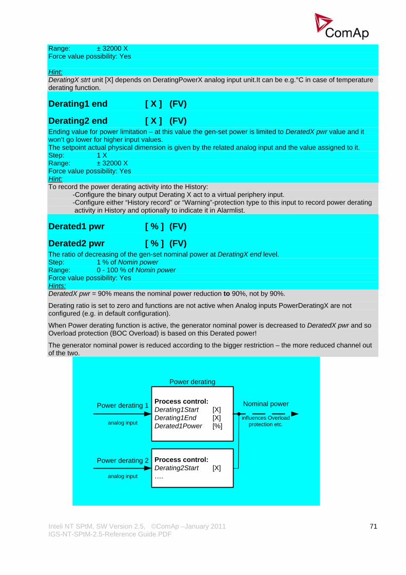
Inteli NT SPtM, SW Version 2.5, ©ComAp –January 2011 IGS-NT-SPtM-2.5-Reference Guide.PDF
71
Range: ± 32000 X Force value possibility: Yes Hint: DeratingX strt unit [X] depends on DeratingPowerX analog input unit.It can be e.g.°C in case of temperature derating function.
Derating1 end [ X ] (FV)
Derating2 end [ X ] (FV) Ending value for power limitation – at this value the gen-set power is limited to DeratedX pwr value and it won’t go lower for higher input values. The setpoint actual physical dimension is given by the related analog input and the value assigned to it. Step: 1 X Range: ± 32000 X Force value possibility: Yes Hint: To record the power derating activity into the History:
-Configure the binary output Derating X act to a virtual periphery input. -Configure either “History record” or “Warning”-protection type to this input to record power derating activity in History and optionally to indicate it in Alarmlist.
Derated1 pwr [ % ] (FV)
Derated2 pwr [ % ] (FV) The ratio of decreasing of the gen-set nominal power at DeratingX end level. Step: 1 % of Nomin power Range: 0 - 100 % of Nomin power Force value possibility: Yes Hints: DeratedX pwr = 90% means the nominal power reduction to 90%, not by 90%.
Derating ratio is set to zero and functions are not active when Analog inputs PowerDeratingX are not configured (e.g. in default configuration).
When Power derating function is active, the generator nominal power is decreased to DeratedX pwr and so Overload protection (BOC Overload) is based on this Derated power!
The generator nominal power is reduced according to the bigger restriction – the more reduced channel out of the two.
Process control:Derating1Start [X]Derating1End [X]Derated1Power [%]
Power derating 1
analog input
Nominal power
influences Overloadprotection etc.
Power derating
Process control:Derating2Start [X]….
Power derating 2
analog input
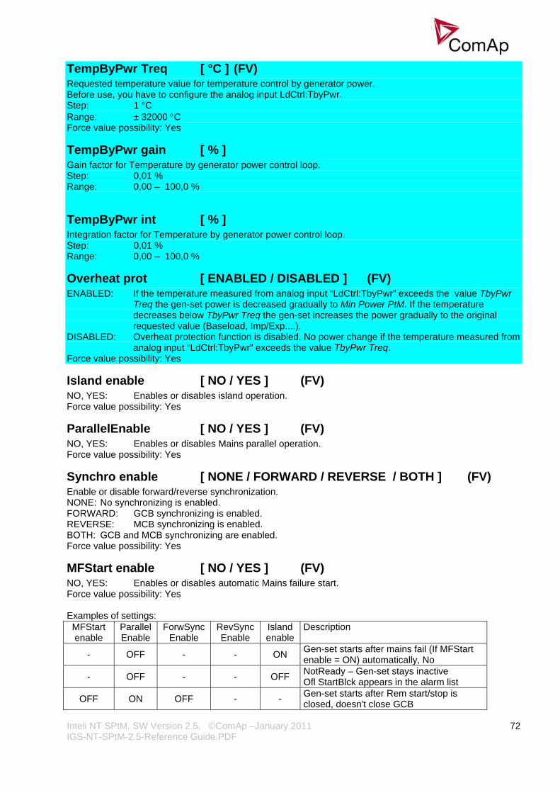
Inteli NT SPtM, SW Version 2.5, ©ComAp –January 2011 IGS-NT-SPtM-2.5-Reference Guide.PDF
72
TempByPwr Treq [ °C ] (FV) Requested temperature value for temperature control by generator power. Before use, you have to configure the analog input LdCtrl:TbyPwr. Step: 1 °C Range: ± 32000 °C Force value possibility: Yes
TempByPwr gain [ % ] Gain factor for Temperature by generator power control loop. Step: 0,01 % Range: 0,00 – 100,0 %
TempByPwr int [ % ] Integration factor for Temperature by generator power control loop. Step: 0,01 % Range: 0,00 – 100,0 %
Overheat prot [ ENABLED / DISABLED ] (FV) ENABLED: If the temperature measured from analog input “LdCtrl:TbyPwr” exceeds the value TbyPwr
Treq the gen-set power is decreased gradually to Min Power PtM. If the temperature decreases below TbyPwr Treq the gen-set increases the power gradually to the original requested value (Baseload, Imp/Exp....).
DISABLED: Overheat protection function is disabled. No power change if the temperature measured from analog input “LdCtrl:TbyPwr” exceeds the value TbyPwr Treq.
Force value possibility: Yes
Island enable [ NO / YES ] (FV) NO, YES: Enables or disables island operation. Force value possibility: Yes
ParallelEnable [ NO / YES ] (FV) NO, YES: Enables or disables Mains parallel operation. Force value possibility: Yes
Synchro enable [ NONE / FORWARD / REVERSE / BOTH ] (FV) Enable or disable forward/reverse synchronization. NONE: No synchronizing is enabled. FORWARD: GCB synchronizing is enabled. REVERSE: MCB synchronizing is enabled. BOTH: GCB and MCB synchronizing are enabled. Force value possibility: Yes
MFStart enable [ NO / YES ] (FV) NO, YES: Enables or disables automatic Mains failure start. Force value possibility: Yes Examples of settings:
MFStart enable
Parallel Enable
ForwSync Enable
RevSync Enable
Island enable
Description
- OFF - - ON Gen-set starts after mains fail (If MFStart enable = ON) automatically, No
- OFF - - OFF NotReady – Gen-set stays inactive Ofl StartBlck appears in the alarm list
OFF ON OFF - - Gen-set starts after Rem start/stop is closed, doesn't close GCB

Inteli NT SPtM, SW Version 2.5, ©ComAp –January 2011 IGS-NT-SPtM-2.5-Reference Guide.PDF
73
OFF ON ON - OFF
Gen-set starts after Rem start/stop is closed, synchronizes, closes GCB, at Mains fail both MCB and GCB are opened control unit stays NotReady
OFF ON OFF ON OFF NotReady – Gen-set stays inactive Ofl StartBlck appears in the alarm list
OFF ON OFF OFF ON
If Mains fails Gen-set starts after Rem start/stop is closed, GCB is closed (island operation), if Mains is ok, Genset stays inactive
OFF ON ON OFF ON
Gen-set starts after Rem start/stop is closed, synchronizes, closes GCB, if Mains fails, opens MCB, stays in Island, Mains return, GCB opened and MCB is closed
OFF ON ON ON ON
Gen-set starts after Rem start/stop is closed, synchronizes, closes GCB, if Mains fails, MCB is opened, gen-set runs in Island, reverse synchr., MCB closes
ON ON ON OFF OFF When Mains failOfl StartBlck appears in the alarm list and gen-set does not start
ON ON OFF OFF ON Gen-set starts after Mains fail, goes to Island, if Mains returns, GCB is opened, MCB is closed
ON ON ON OFF ON Gen-set starts after Mains fail, opens MCB, closes GCB, if Mains returns, opens GCB, closes MCB, Gen-set stops
ON ON OFF ON ON Gen-set starts after Mains fail, opens MCB, closes GCB, if the Mains returns, synchronizes, closes MCB
ON ON ON ON ON
Gen-set starts after Mains fail, synchronizes, closes GCB, if Mains fails, MCB is opened, gen-set runs in Island, reverse synchr., MCB closes
Hint: Valid in AUTO mode only!
#Neutral cont. [ EACH / COMMON ] Setpoint changes behavior of binary output Neutral CB C/O which is used for Neutral contactor control. EACH: Four pole GCB’s are supposed on the engine.
b) When GCB is opened (after start, before stop): Binary output Neutral CB C/O (Neutral contactor) closes when Generator voltage is higher than 85% of Nominal voltage. Binary output Neutral CB C/O (Neutral contactor) opens when Generator voltage is lower than 50% of Nominal voltage.
c) Binary output Neutral CB C/O (Neutral contactor) is opened when gen-set is running in parallel to the
mains (MCB is closed) . COMMON: Three pole GCB’s are supposed for the gen-set.
a) When MCB is opened Neutral contactor closes when Generator voltage (at least one phase) is higher than 85% of Nominal voltage.
b) When MCB is opened Neutral contactor opens when all phases of Genset voltage are lower than 50% of Nominal voltage.
c) When MCB is closed Neutral contactor opens. Hint: Configure Binary output Neutral CB C/O and Binary input Neutral CB fdb Prior to Neutral contactor function is used.

Inteli NT SPtM, SW Version 2.5, ©ComAp –January 2011 IGS-NT-SPtM-2.5-Reference Guide.PDF
74
Neutral contactor fail is detected when no feedback comes within 400ms or when MCB and Neutral contactor are closed for more than 400 ms.
WatchedContr [ ] This setpoint is used at redundant controller to specify the address of the related main controller in CAN-based rendundant systems. Adjust this setpoint to 0 if the controller is not used as redundant or if wired rendundancy system is used. Step: 1 Range: 1 – 16 Force value possibility: No Hint: For details see IGS-NT Redundant controllers Application sheet or controller context help.
Basic settings
Nomin power [ kW – MW* ] (FV) Nominal power of the generator. Step: 0,1 kW / 1 kW / 0,01 MW* Range: 0,1 kW – 320,00 MW* Force value possibility: Yes *Note: The actual setpoint units and range depend on setting of the Power format (see GenConfig manual). Nominal power of the gen-set is also its maximum operation power.
Nomin current [ A ] (FV) This is the current limit for the generator. IDMT over current and short current protections are based on this setpoint. See Generator protections: 2Inom del, Ishort setpoints. Nominal current can be different from generator rated current value. Step: 1 A Range: 1 - 10000 A Force value possibility: Yes
!!! VERY IMPORTANT !!!
• The maximum input current to the controller current terminals is 11 Amps. Higher value is displayed as measured limit, e.g. 15 Amps from CT is measured and displayed as 11 Amps.
• Take special care when selecting CT’s. All available 5 Amp CT’s do not have a range up to 11 Amps.
CT ratio prim [ A ] Gen-set phases Current Transformers ratio – primary side. Step: 1 A Range: 1 – 15000 A
CT ratio sec [ /5A / /1A ] Gen-set phases Current Transformers ratio – secondary side selection /5A or /1A. Available in IG-xxC and IS-NT versions. In standard IG-EE/NT units only 5 A range available. Hint: Do not switch to 1A range unless you have IG-NTC/EEC or IS-NT hardware.
Im3/ErFlCurCTp [ A ] Mains current phase 3 or Earth Fault protection Current Transformer ratio – primary side. Mains CT ratio for single phase Import / Export power and PF measuring. Single phase power value is internally multiplied by three. Step: 1 A

Inteli NT SPtM, SW Version 2.5, ©ComAp –January 2011 IGS-NT-SPtM-2.5-Reference Guide.PDF
75
Range: 1 – 15000 A Hint: Im3 controller terminals have to be connected to mains L3 phase for Import/Export measuring!!! Balanced mains power is expected.
Im3/ErFlCurCTs [ /5A / /1A ] Mains current phase 3 or Earth Fault protection Current Transformer ratio – secondary side selection /5A or /1A. Available in IG-xxC and IS-NT versions. In standard IG-EE/NT units only 5 A range available. Hint: Do not switch to 1A range unless you have IG-NTC/EEC or IS-NT hardware.
VT ratio [ /1 ] Gen-set Voltage Transformers ratio. Step: 0,01 V / V Range: 0,01 – 500,00 V / V
Vg InpRangeSel [ 277 V / 120 V ] Gen-set voltage sensing inputs range selection. Available in IG-xxC and IS-NT versions. In standard IG-EE/NT units only 277 V range available. Hint: The range 277 V is suitable for both European (230 V) and American (277 V) measurement. The range 120 V is intended for high-voltage applications where voltage transformers with output range 100 V are used, or for alternative American (120 V) measurement. Do not switch to 120V range unless you have IG-NTC/EEC or IS-NT hardware.
Vm VT ratio [ /1 ] Mains Voltage Transformers ratio. Step: 0,01 V / V Range: 0,01 – 500,00 V / V Hint: Set VT ratio to 1,0 if no Voltage Transformers are used.
Vm InpRangeSel [ 277 V / 120 V ] Mains voltage sensing inputs range selection. Available in IG-xxC and IS-NT versions. In standard IG-EE/NT units only 277 V range available – the setpoint setting is not important. Hint: The range 277 V is suitable for both European (230 V) and American (277 V) measurement. The range 120 V is intended for high-voltage applications where voltage transformers with output range 100 V are used, or for alternative American (120 V) measurement. Do not switch to 120V range unless you have IG-NTC/EEC or IS-NT hardware.
GenNomV [ V – kV* ] (FV) Nominal generator voltage (phase to neutral). Step: 1 V / 0,01 kV* Range: 80 V – 346,41 kV* Force value possibility: Yes *Note: The actual setpoint units and range depend on setting of the Power format (see GenConfig manual). Hint: The nominal value can be externally changed using Force value function. However, it is intended for changes between standard nominal voltages only (230 / 120 V) using ForceValueInXX source setpoints. It is prohibited to use another controller values as a source for Force value in this case!!! Both Gen and Mains nominal voltages must be set to the same value when no VT is used.

Inteli NT SPtM, SW Version 2.5, ©ComAp –January 2011 IGS-NT-SPtM-2.5-Reference Guide.PDF
76
GenNomVph-ph [ V – kV* ] Nominal generator voltage (phase to phase). Step: 1 V / 0,01 kV* Range: 130 V – 600,00 kV *Note: The actual setpoint units and range depend on setting of the Power format (see GenConfig manual). Hint: If one of the nominal voltages is changed, the other is automatically adjusted to correspond with the new value. E.g. if GenNomV is changed to 220 V, the GenNomVph-ph is changed to 220*1,73 = 381 V. Both Gen and Mains nominal voltages must be set to the same value when no VT is used.
MainsNomV [ V – kV* ] (FV) Nominal mains voltage (phase to neutral). Step: 1 V / 0,01 kV* Range: 80 V – 346,41 kV* Force value possibility: Yes *Note: The actual setpoint units and range depend on setting of the Power format (see GenConfig manual). Hint: The nominal value can be externally changed using Force value function. However, it is intended for changes between standard nominal voltages only (230 / 120 V) using ForceValueInXX source setpoints. It is prohibited to use another controller values as a source for Force value in this case!!! Both Gen and Mains nominal voltages must be set to the same value when no VT is used.
MainsNomVph-ph [ V – kV* ] Nominal mains voltage (phase to phase). Step: 1 V / 0,01 kV* Range: 130 V – 600,00 kV* *Note: The actual setpoint units and range depend on setting of the Power format (see GenConfig manual). Hint: Both Gen and Mains nominal voltages must be set to the same value when no VT is used.
FixVoltProtSel [ PHASE-NEUTRAL / PHASE-PHASE ] PHASE-NEUTRAL: The generator and mains/bus fixed voltage protections are based on phase-to-neutral
voltages. PHASE-PHASE: The generator and mains/bus fixed voltage protections are based on phase-to-phase
voltages. Hint: Values in user configurable voltage protection have to be changed manually (e.g. V L1-N, L2-N, L3-N for V L1-L2, L2-L3, L3-L1 or vice versa).
Nominal freq [ Hz ] (FV) Nominal generator frequency (usually 50 or 60 Hz). Step: 1Hz Range: 45 – 65 Hz Force value possibility: Yes Hint: The nominal value can be externally changed using Force value function. However, it is intended for changes between standard nominal frequencies only (50 / 60 Hz) using ForceValueInXX source setpoints. It is prohibited to use another controller values as a source for Force value in this case!!!
Gear teeth [ ] Number of teeth on the engine’s flywheel for the pick-up sensor. Set to Fgen->RPM, if no pick-up sensor is used. In that case, engine speed is calculated from the generator frequency. Step: 1

Inteli NT SPtM, SW Version 2.5, ©ComAp –January 2011 IGS-NT-SPtM-2.5-Reference Guide.PDF
77
Range: Fgen->RPM, 1 – 500 Hint: Generator frequency can be used (for RPM measuring) only when generator voltage (min 15V) is present during cranking. This is in general not suitable option for gas engines! Gear teeth should not be set to zero when Engine params:Fuel solenoid = GAS ENGINE (it is likely that RPM would not reach 30, the gen-set wouldn’t start and gas valve would not open – see Fuel solenoid). Some electronic engines provide their own cranking and preheat cycle (e.g. CAT EMCP3). In such case, set Gear teeth = 0, otherwise it may not be possible to start the engine.
Nominal RPM [ RPM ] (FV) Nominal speed of the engine. Step: 1RPM Range: 100 – 4000 RPM Force value possibility: Yes The following table shows the relationship between frequency and nominal RPM due to generator poles:
Generator poles 50 Hz 60 Hz 2 3000 3600 4 1500 1800 6 1000 1200
Hint: Generator frequency can be used (for RPM measuring) only when generator voltage (min 10V) is present during cranking. When pick-up cut (fail) comes, InteliSys detects under speed and stops the engine.
ControllerMode [ OFF / MAN / SEM / AUT / TEST ] (FV) Equivalent to Controller mode changes by MODE→ or ←MODE buttons. Force value possibility: Yes Hint: Mode change can be separately password protected.
FltRes GoToMAN [ DISABLED / ENABLED ] (FV) DISABLED: Controller stays in AUT mode after Fault reset . ENABLED: Automatic switch from SEM / AUT / TEST to MAN mode after Fault reset to avoid automatic
engine start. This function is active for all 2nd-level protections (Shut down, Slow stop, ElProt, Off-load).
Force value possibility: Yes Hint: It is not possible to reset a Fault when Binary input Remote TEST is closed or another mode forcing function is active. Set to ENABLED to avoid automatic engine start when Fault reset button is pressed after shut down in automatic mode.
Local buttons [ PANEL / EXTBUTTONS / BOTH ] PANEL: Only the buttons on the controller front panel are enabled. EXTBUTTONS: Only the external signals (copies of the panel buttons) are enabled. BOTH: Both controller buttons and external signals are enabled. Hint: This switch is valid for these signals: GCBButton, MCBButton, FaultResButton, HornResButton, StartButton, StopButton.
DispBaklightTO [ min ] (FV) Timeout after which the display backlight is switched off. OFF = the backlight is off all the time, NO TIMEOUT = the backlight is on all the time. Step: 1 min Range: OFF (= 0), 1 – 240 min, NO TIMEOUT (= 241) Force value possibility: Yes
Inteli NT SPtM, SW Version 2.5, ©ComAp –January 2011 IGS-NT-SPtM-2.5-Reference Guide.PDF
78
DispBklStrtOff [ DISABLED / ENABLED ] (FV) This setpoint determines if display backlight is switched on/off during the gen-set start. This parameter is effective for all the displays not only for the internal one. Force value possibility: Yes
ConvCoefPulse [ ] This setpoint adjusts the rate of increasing of the PulseCounter1 (integrating internal counters that can be seen at PulseCounter1). The setpoint assigns number of pulses (BI:PulseCounter1) to increase the PulseCounter integrating value by 1. Step: 1/X Range: 1 – 65000 1/X Example: Number of pulses on the physical input BI: PulseCounter1: 10 ConvCoefPulse1 = 2 Value of the PulseCounter1 integrating counter: 5
ConvCoefPulse1 - 4 [ ] This setpoint adjusts the rate of increasing of the PulseCounter1 – 4 (integrating internal counters that can be seen at PulseCounter2-4). The setpoint assigns number of pulses (BI:PulseCounter2 – 4) to increase the PulseCounter integrating value by 1. Step: 1/X Range: 1 – 65000 1/X Example: Number of pulses on the physical input BI: PulseCounter1: 10 ConvCoefPulse1 = 2 Value of the PulseCounter1 integrating counter: 5
Comms settings
Gen-set name User-defined name, used for controller identification at remote connections. Gen-set name is max 15 characters long and has to be entered using PC software. Hint: The setpoint can be changed using PC SW only (e.g. InteliMonitor). Gen-set name isn’t affected by GenConfig SW.
Contr. address [ ] Controller CAN bus and RS-485 identification number. Each controller in the group has to have its own unique number. Step: 1 Range: 1 to 32 Hint: When opening Direct or Modem connection to the controller (using PC monitoring/control SW), the Contr. address has to correspond to the Gen-set setting in PC SW.
RS232(1) mode [ DIRECT / MODEM (HW) / MODEM (SW) / MODBUS-DIRECT / MODBUS-MDM(HW) / ECU LINK ]
Communication protocol selection for RS232(1) line. DIRECT: Connection to a local PC running InteliMonitor. RS232 or RS485 (with internal or
external converter) lines can be used. Set this also for IG-IB connected via RS232 line.
Inteli NT SPtM, SW Version 2.5, ©ComAp –January 2011 IGS-NT-SPtM-2.5-Reference Guide.PDF
79
MODEM (HW): Analog/GSM/ISDN modem connection. Select this for standard modems with HW flow control. If selected and no CTS signal is detected, communication may not work correctly.
MODEM (SW): Analog/GSM/ISDN modem connection. Select this for modems without HW flow control – controller will use SW flow control signals XOn, Xoff, so only TxD and RxD signals need to be connected between the controller and the modem.
MODBUS-DIRECT: Modbus protocol for direct connection to PLC / external SCADA terminal. Communication speed can be selected via setpoint RS232(1)MBCSpd.
MODBUS-MDM(HW):Modbus protocol for modem (remote) connection to PLC / external SCADA terminal. Communication speed can be selected via setpoint RS232(1)MBCSpd.
ECU LINK: Port redirected to connect the ECU with special (not J1939) interface, e.g. Cummins Modbus.
Hint: Detail description of Modbus protocol see in Communication guide.
RS232(2) mode [ DIRECT / MODEM (HW) / MODEM (SW) / MODBUS-DIRECT / MODBUS-MDM(HW) / ECU LINK]
Communication protocol selection for RS232(2) line. Description is the same like for RS232(1) mode. Available only in IS-NT and in IG-xxC versions. Hint: Detail description of Modbus protocol see in Communication guide. ECU LINK mode available only starting from FW versions IGS-NT-2.2 or higher together with IGS-NT-E-COM-1.1 or higher.
RS232(1)MBCSpd [ 9600 bps / 19200 bps / 38400 bps / 57600 bps ] Defines the communication speed on RS232(1) line when ModBus mode is selected.
RS232(2)MBCSpd [ 9600 bps / 19200 bps / 38400 bps / 57600 bps ] Defines the communication speed on RS232(2) line when ModBus mode is selected. Available only in IS-NT and in IG-xxC versions.
RS485(1) conv. [ DISABLED / ENABLED ] If set to ENABLED, the communication RS232(1) port is redirected to the built-in RS485 converter (IG-Display connector). Hint: Applicable only for DIRECT, MODBUS-DIRECT and ECU LINK modes. This converter is not isolated! For ports position and description see Installation guide. RS485(1) has to be swiched to Disabled when IG-Display (Remote Display) is used.
RS485(2) conv. [ DISABLED / ENABLED ] If set to ENABLED, the communication RS232(2) port is redirected to the built-in isolated RS485 converter. Available only in IS-NT and in IG-xxC versions. Hint: Applicable only for DIRECT, MODBUS-DIRECT and ECU LINK modes.
RS232(1)MdmIni [ ] Auxiliary modem initialization string – executed after the default modem initialization string. Used with modem connected to the RS232(1) communication port. Hint: Applicable only for MODEM(HW), MODEM(SW) and MODBUS-MDM(HW) modes. Use for special AT command setting of your modem if default string does not initiate the modem properly. AT commands must be separated using semicolon “;”, max. length 31 characters. The setpoint can be changed only using PC SW when configuring IG-EE/NT.
Inteli NT SPtM, SW Version 2.5, ©ComAp –January 2011 IGS-NT-SPtM-2.5-Reference Guide.PDF
80
RS232(2)MdmIni [ ] Auxiliary modem initialization string – executed after the default modem initialization string. Used with modem connected to the RS232(2) communication port. Available only in IS-NT and in IG-xxC versions. Hint: Applicable only for MODEM(HW), MODEM(SW) and MODBUS-MDM(HW) modes. Use for special AT command setting of your modem if default string does not initiate the modem properly. AT commands must be separated using semicolon “;”, max. length 31 characters. The setpoint can be changed only using PC SW when configuring IG-EE/NT.
CAN bus mode [ 32C / 8C ] CAN bus speed selection. 32C: High speed CAN (250 kbps) applicable up to 32 controllers, CAN bus length limited up to 200 meters. 8C: Low speed CAN (50 kbps) applicable up to 8 controllers, CAN bus length limited up to 900 meters. Hint: Low speed use for long distance connection only. Set all connected controllers to the same speed. If having problems with needed CAN bus length, see Communication guide / I-CR module.
CAN2emptDetect [ DISABLED / ENABLED ] (FV) Enables the detection of missing intercontroller CAN connection. If enabled and no other controllers are detected on the CAN bus (the complete bus, not only within the logical group), this protection activates. Force value possibility: Yes
LB/UART Log [ DISABLED / ENABLED ] (FV) Enables history logging of IG-IB / I-LB connection. Force value possibility: Yes Hint: If communication via IG-IB is interrupted for more than 5s, it is automatically terminated. If it is established again after this period, it is considered as a newly created connection and a new record “Terminal” is done into history in case of LB/UART Log = ENABLED. This may cause overfilling of the history in case of some monitoring tools, e.g. InteliSupervisor.
CANAddrSwitch1 [ MODEM / OTHER ] This setpoint defines whether CAN address 122 is used for modem communication over ComAp I-LB module or direct communication of another device: MODEM: Default setting for modem communication OTHER: Address 122 can be used by other devices to read data via CAN bus the same way as if using
addresses 123 and 124
CANAddrSwitch2 [ MODEM / OTHER ] This setpoint defines whether CAN address 122 is used for modem communication over ComAp I-LB module or direct communication of another device: MODEM: Default setting for modem communication OTHER: Address 125 can be used by other devices to read data via CAN bus the same way as if using
addresses 123 and 124
IP addr mode [ FIXED / AUTOMATIC ] The setpoint is used to select the method how the ethernet connection is adjusted. FIXED: The ethernet connection is adjusted fixedly according to the setpoints IP address, Net mask,
Gateway IP, DNS IP. . This method should be used for classic ethernet or Internet connection. When this type of connection is opening the controller is specified by it's IP address. That means it would be inconvenient if the IP address were not fixed (static).
Inteli NT SPtM, SW Version 2.5, ©ComAp –January 2011 IGS-NT-SPtM-2.5-Reference Guide.PDF
81
AUTOMATIC: The ethernet connection settings is obtained automatically from the DHCP server. The obtained settings is then copied to the related setpoints. If the process of obtaining the settings from DHCP server is not successful the value 000.000.000.000 is copied to the setpoint IP address and the module continues trying to obtain the settings. This method is beneficial for AirGate connection as it makes the connection very easy, in fact "plug and play". When this type of connection is opening the controller is specified by it's AirGate ID and the IP address does not play any role.
IP address [ - ] In fixed settings mode this setpoint is used to adjust the IP address of the ethernet interface of the controller. Ask your IT specialist for help with this setting. In Automatic settings mode this setpoint is used to display the IP address, which has been assigned by the DHCP server.
Net mask [ - ] In fixed settings mode this setpoint is used to adjust the IP address of the ethernet interface of the controller. Ask your IT specialist for help with this setting. In Automatic settings mode this setpoint is used to display the IP address, which has been assigned by the DHCP server.
Gateway IP [ - ] In fixed settings mode this setpoint is used to adjust the IP address of the gateway of the network segment where the controller is connected. In Automatic settings mode this setpoint is used to display the gateway IP address which has been assigned by the DHCP server. A gateway is a device which connects the respective segment with the other segments and/or Internet.
ComApProtoPort [ 1 to 255 ] This setpoint is used to adjust the port, which is used for ethernet connection to a PC with any of ComAp PC program (i.e. InteliMonitor, GenConfig). This setpoint should be adjusted to 23, which is the default port used by all ComAp PC programs. A different value should be used only in special situations as e.g. sharing one public IP address among many controllers or to overcome a firewall restrictions.
AirGate server [ DISABLED / ENABLED ] This setpoint selects the ethernet connection mode.
DISABLED: This is a standard mode, in which the controller listens to the incoming traffic and answers the TCP/IP queries addressed to him. This mode requires the controller to be accessible from the remote device (PC), i.e. it must be accessible at a public and static IP address if you want to connect to it from the Internet.
ENABLED: This mode uses the "AirGate" service, which hides all the issues with static/public address into a black box and you do not need to take care about it. You just need only a connection to the Internet. The AirGate server address is adjusted by the setpoint AirGate addr.
AirGate IP [ - ] This setpoint is used for entering the domain name or IP address of the AirGate server. Use the free AirGate server provided by ComAp at address airgate.comap.cz if your company does not operate it's own AirGate server.
SMTP authent [ DISABLED / ENABLED ] Switch this setpoint to ENABLED if your SMTP server requires authentificated access. You have also adjust SMTP user name and SMTP password. Ask your internet provider or IT manager for this information. Hint: Most of public free SMTP servers require authentification. You will get instructions when you register to the freemail service.

Inteli NT SPtM, SW Version 2.5, ©ComAp –January 2011 IGS-NT-SPtM-2.5-Reference Guide.PDF
82
SMTP user name [ - ] Use this setpoint to enter the user name for the SMTP server if SMTP authentification is enabled.
SMTP password [ - ] Use this setpoint to enter the password for the SMTP server if SMTP authentification is enabled.
SMTP address [ - ] This setpoint is used for entering the domain name (e.g. smtp.yourprovider.com) or IP address (e.g. 74.125.39.109) of the SMTP server. Please ask your internet provider or IT manager for this information. Hint: You may also use one of free SMTP servers, e.g. smtp.gmail.com. However, please note that some free SMTP servers may cause delays (in hours..) when sending e-mails. If you do not want to send active e-mails, you may leave this setpoint blank, as well as other setpoints related to SMTP server and e-mail settings. Proper setting of SMTP-related setpoints as well as controller mailbox are essential for sending alerts via e-mails
Contr mailbox [ - ] Enter an existing e-mail address into this setpoint. This address will be used as sender address in active e-mails that will be sent from the controller. Do not enter your or other recipient's e-mail address. Recipient's addresses are to be entered into the setpoints AcallCH1-Addr, AcallCH2-Addr and AcallCH3-Addr. Hint: Most of SMTP server will reject sending e-mails that contain nonexisting address in the sender address field.
Time zone [ - ] This setpoint is used to select the time zone where the controller is located. See your computer time zone setting (click on the time indicator located in the rightmost position of the the windows task bar) if you are not sure about your time zone. Hint: If the time zone is not selected properly the active e-mails may contain incorrect information about sending time, which may result in confusion when the respective problem actually occured.
DNS IP [ - ] In fixed settings mode this setpoint is used to adjust the domain name server (DNS), which is needed to traslate domain names in e-mail addresses and server names into correct IP addresses. In Automatic settings mode this setpoint is used to display DNS server, which has been assigned by the DHCP server.
ECU Diag [ DISABLED / ENABLED ] (FV) When set to disabled, the ECU advanced diagnostics is disabled to allow the cooperation with external diagnostics tool. Alarm list indication “ECU Diag disabled” is indicated when ECU diagnostics is disabled. Force value possibility: Yes
SHxOcol detect [ DISABLED / ENABLED ] This setpoint is dedicated for virtual peripheries; it can enable / disable error messages when more then one master (source) is configured.
Inteli NT SPtM, SW Version 2.5, ©ComAp –January 2011 IGS-NT-SPtM-2.5-Reference Guide.PDF
83
Engine params
Starting RPM [ RPM ] (FV) “Firing” speed when controller stops cranking. Step: 1 RPM Range: 0 – 1500 RPM Force value possibility: Yes Hint: Under speed limit is given by Starting RPM value once the Under speed protection has been enabled. The Under speed protection becomes active 5s after reaching Starting RPM or other engine running condition regardless of the setting of Idle time (transition Idle -> Nominal RPM). Starting procedure for genset controller equipped with own starting algorithm follow Trouble shouting guide.
Starting POil [ bar ] (FV) Oil pressure limit for controller cranking termination = one of the engine running indications. To activate this function an Analog input must be configured to Analog logical input Oil press. Step: 0,1 bar Range: 0 – 10,0 bar Force value possibility: Yes Hint: Step, Range and dimension depend on corresponding Analog input sensor characteristic.
Prestart time [ s ] (FV) The binary output PRESTART is active prior to engine start for this time. Set to zero if you want to disable this function. Step: 1s Range: 0 – 3600 s Force value possibility: Yes
Prelubr time [ s ] (FV) This is the time the binary output PRELUBR PUMP is active. The controller will activate the binary output PRELUBR PUMP for this time, then pause for Prelubr pause, then activate it again. This will continue the entire time the engine is not running and the controller is not in OFF mode and EMERGENCY STOP is not active. Step: 1s Range: 0 – 3600 s Force value possibility: Yes
Prelubr pause [ min ] (FV) Pause between prelubrication cycles. Step: 1 min Range: 1 – 3000 min Force value possibility: Yes
MaxCrank time [ s ] (FV) The maximum time the starter motor is energized. Step: 1s Range: 1 – 240 s Force value possibility: Yes Hint: If Fuel solenoid = GAS ENGINE, the engine will crank 25% longer with closed fuel valve after the last unsuccessful attempt in order to ventilate the remaining gas. If magnetic pickup is used and the controller does not receive non-zero RPM within 2s after energizing the starter motor, then cranking pause follows immediately. If Fuel solenoid = DIESEL, magnetic pickup is used and the controller does not receive RPM>2 within 5s after energizing the starter motor, then cranking pause follows immediately.

Inteli NT SPtM, SW Version 2.5, ©ComAp –January 2011 IGS-NT-SPtM-2.5-Reference Guide.PDF
84
CrnkFail pause [ s ] (FV) Pause between crank attempts. Step: 1s Range: 5 – 60 s Force value possibility: Yes
Crank attempts [ ] (FV) Max number of crank attempts. Step: 1 Range: 1 – 10 Force value possibility: Yes Hint: A pickup fail shutdown is activated if digital output starter is closed and the controller measures zero RPM (from the pickup) and non-zero frequency.
Idle time [ s ] (FV) Idle time delay starts when RPM exceeds Start RPM. A start fail is detected if the RPM drops below 2 RPM during Idle time. Binary output IDLE/NOMINAL is opened before and during engine start (during Idle time) and after engine start is activated - in Cooling state, only if Engine params: Cooling Speed = NOMINAL. Step: 1 s Range: 1 – 3600 s Force value possibility: Yes Hint: The Under speed protection becomes active 5s after reaching Starting RPM or other engine running condition regardless of the setting of Idle time (transition Idle -> Nominal RPM).
Min stab time [ s ] (FV) This is the minimum time the controller will wait, after switching the engine to nominal RPM, to close the GCB (the delay ensures that the GCB is closed with correct generator frequency/voltage). Step: 1s Range: 1 – Max stab time s Force value possibility: Yes
Max stab time [ s ] (FV) This is the maximum time the controller will wait for generator voltage and frequency to build up, after switching the engine to nominal RPM. Step: 1s Range: Min stab time – 3600 s Force value possibility: Yes Hint: When generator voltage in Max stab time does not reach defined limits (see Gener protect group), an alarm occurs and the gen-set will cool down and stop.
Warming load [ % ] (FV) The requested load during warm-up period after GCB is closed. In parallel to mains operation only. Step: 1 % of Nominal power Range: 0 – 100 % of Nominal power Force value possibility: Yes Hint Warming temp Analog input has to be configured. Otherwise the warm-up procedure does not work.
Warming temp [ °C ] (FV) The requested engine water temperature to finish the warming period. If this limit reached, the actual Warming time is shorter than Max warm time setpoint. Step: 1 °C Range: ± 32000 °C

Inteli NT SPtM, SW Version 2.5, ©ComAp –January 2011 IGS-NT-SPtM-2.5-Reference Guide.PDF
85
Force value possibility: Yes
Max warm time [ s ] (FV) If the required Warming temp is not achieved within this time, the warming period is completed anyway. Step: 1 s Range: 0 – 3600 s Force value possibility: Yes
Cooling speed [ NOMINAL / IDLE ] (FV) Determines function of Idle/Nominal binary output during cooling. NOMINAL: Gen-set cools down on nominal speed, generator voltage and frequency protections are active. IDLE: Gen-set cools down on idle speed, generator protections are deactivated (except of Gen >V Sd). Force value possibility: Yes
Cooling time [ s ] (FV) Runtime of the unloaded gen-set to cool down the engine before stop. Step: 1s Range: 0 – 3600 s Force value possibility: Yes
CoolDnAfterBOC [STOP / INFIN COOLING] (FV) STOP = opens breaker, starts cooling, after set time stops engine INFIN COOLING = opens breaker, starts cooling; engine stays in that state for infinite time; after acknowledging all the BOC protections (and all the others which can block engine running) it is possible to switch back from cooling; in AUT mode automatically, in MAN mode after pushing Start button Force value possibility: Yes
Cooldown optim [ DISABLED / ENABLED ] DISABLED: Gen-set cooling period is given strictly by the setpoint Cooling time. ENABLED: Gen-set cooling period depends on the load that was present in the moment of Stop command. I.e. the higher the produced power has been, the longer cooling period will be. It is a linear equation:
– Act power = 100% of the Nomin power => cooling period = Cooling time – Act power = 50% of the Nomin power => cooling period = Cooling time / 2
AfterCool time [ s ] (FV) Runtime of the cooling pump after engine stop. Binary output COOLING PUMP is closed when the engine starts and opens AfterCoolTime delayed after gen-set stops. Step: 1s Range: 0 – 3600 s Force value possibility:Yes Hint: For After cooling function configure the binary output COOLING PUMP.
Stop time [ s ] (FV) Stop time value means the minimum time for which Stop solenoid will be closed. If the engine stopping procedure will take longer time, the Stop solenoid stays closed until all signs of moving engine have disappeared (RPM, Vg, fg, Oil press, RunIndicationX) + 10 seconds more to have some safety overlap. After Stop time has elapsed and the engine is still moving, the alarm "Sd Stop fail" is produced. Conditions for stopped engine: RPM=0, Ug < 10 V, fg = 0 Hz, Oil press < Ain Sd level, all RunIndicationX inputs deactivated. However, this is not a normal situation and should be solved by increasing the Stop time setpoint. Step: 1s Range: 0 – 240 s Force value possibility:Yes

Inteli NT SPtM, SW Version 2.5, ©ComAp –January 2011 IGS-NT-SPtM-2.5-Reference Guide.PDF
86
SDVentil time [ s ] If Fuel solenoid setpoint is set to GAS ENGINE, this setpoint adjusts the time of starter motor to be switched on for engine preventilation in case of a first start attempt after a shutdown or controller switch-on. Step: 1s Range: 0 – 60 s
Fuel solenoid [ DIESEL ENGINE / GAS ENGINE ] Selection of Fuel solenoid output function: DIESEL ENGINE: In this mode of operation the output closes to energize the fuel solenoid and enable
the engine to start. The delay or advance of activation in relation to Starter output is defined by FuelSol offset.
GAS ENGINE: In this mode of operation the output closes to open the gas valve and enable the engine to start. The output closes only if RPM > 30 (i.e. the starter motor is engaged) with FuelSol offset.
The output opens if there is any reason to stop the engine or in pause between repeated starts. Hint: In the case of gas engine, the underspeed protection cannot be blocked by the Sprinkler function. For gas engines, it is strongly recommended to use the pick-up sensor, as non-zero RPM detection is required during the start procedure.
FuelSol offset [ s ] This setpoint adjusts the Fuel solenoid output activation in relation to Starter output. Positive values mean that fuel valve is opened after the Starter, negative values mean that it is open before. Negative values are suppressed if Fuel solenoid = GAS ENGINE. Step: 0,1 s Range: -5,0 – 5,0 s
D+ function [ DISABLED / CHRGFAIL / ENABLED ] DISABLED:The D+ terminal is not used. CHRGFAIL:The D+ terminal is used for charge fail detection only. ENABLED: The D+ terminal is used for both functions – “running engine” detection and charge fail detection. Hint: Expected behavior of the D+ terminal with regard to connection of the D+ alternator terminal, alternator type and setting the D+ function setpoint:
1. If the D+ terminal is not connected, its voltage will be ~0V when the engine is not running, ~Ubat -4V during the start and ~0V when the engine is running
2. If the D+ terminal is connected to a standard alternator D+ input, it will have ~0V when the engine is not running, the voltage will increase from 0 to Ubat as the alternator speed increases during the start and will have ~Ubat when the engine is running
3. There are some alternators equipped with electronic regulators, which are "self-excited" and do not provide standard D+ terminal. They may provide other terminal ("L" or other), which is designed for connection of a red bulb failure indication instead of D+ . However, this terminal can be "open collector" only and it will not work with ComAp controllers as it does not provide voltage.
Bin selector 1-4 [ OFF / ON ] (FV) These setpoints are linked with binary outputs Bin selector X. Activity of these outputs depends on setpoint state: OFF: The corresponding binary output is not active. ON: The corresponding binary output is active. Force value possibility:Yes The setpoints are intended for ECU control, e.g. nominal speed switching. The binary output values can be transmitted to ECU and control particular functions.
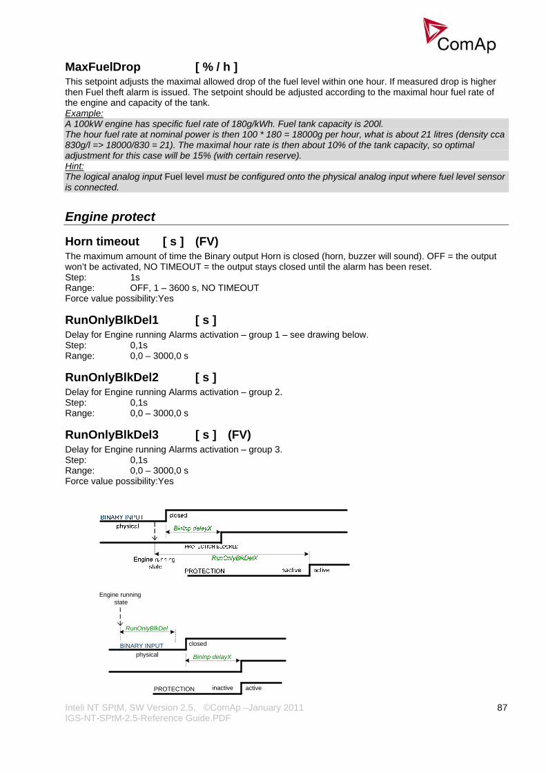
Inteli NT SPtM, SW Version 2.5, ©ComAp –January 2011 IGS-NT-SPtM-2.5-Reference Guide.PDF
87
MaxFuelDrop [ % / h ] This setpoint adjusts the maximal allowed drop of the fuel level within one hour. If measured drop is higher then Fuel theft alarm is issued. The setpoint should be adjusted according to the maximal hour fuel rate of the engine and capacity of the tank. Example: A 100kW engine has specific fuel rate of 180g/kWh. Fuel tank capacity is 200l. The hour fuel rate at nominal power is then 100 * 180 = 18000g per hour, what is about 21 litres (density cca 830g/l => 18000/830 = 21). The maximal hour rate is then about 10% of the tank capacity, so optimal adjustment for this case will be 15% (with certain reserve). Hint: The logical analog input Fuel level must be configured onto the physical analog input where fuel level sensor is connected.
Engine protect
Horn timeout [ s ] (FV) The maximum amount of time the Binary output Horn is closed (horn, buzzer will sound). OFF = the output won’t be activated, NO TIMEOUT = the output stays closed until the alarm has been reset. Step: 1s Range: OFF, 1 – 3600 s, NO TIMEOUT Force value possibility:Yes
RunOnlyBlkDel1 [ s ] Delay for Engine running Alarms activation – group 1 – see drawing below. Step: 0,1s Range: 0,0 – 3000,0 s
RunOnlyBlkDel2 [ s ] Delay for Engine running Alarms activation – group 2. Step: 0,1s Range: 0,0 – 3000,0 s
RunOnlyBlkDel3 [ s ] (FV) Delay for Engine running Alarms activation – group 3. Step: 0,1s Range: 0,0 – 3000,0 s Force value possibility:Yes
BINARY INPUT
BinInp delayXphysical
closed
Engine running state
RunOnlyBlkDel
PROTECTION activeinactive
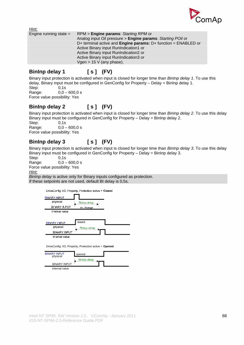
Inteli NT SPtM, SW Version 2.5, ©ComAp –January 2011 IGS-NT-SPtM-2.5-Reference Guide.PDF
88
Hint: Engine running state = RPM > Engine params: Starting RPM or Analog input Oil pressure > Engine params: Starting POil or D+ terminal active and Engine params: D+ function = ENABLED or Active Binary input RunIndication1 or Active Binary input RunIndication2 or Active Binary input RunIndication3 or Vgen > 15 V (any phase).
BinInp delay 1 [ s ] (FV) Binary input protection is activated when input is closed for longer time than BinInp delay 1. To use this delay, Binary input must be configured in GenConfig for Property – Delay = BinInp delay 1. Step: 0,1s Range: 0,0 – 600,0 s Force value possibility: Yes
BinInp delay 2 [ s ] (FV) Binary input protection is activated when input is closed for longer time than BinInp delay 2. To use this delay Binary input must be configured in GenConfig for Property – Delay = BinInp delay 2. Step: 0,1s Range: 0,0 – 600,0 s Force value possibility: Yes
BinInp delay 3 [ s ] (FV) Binary input protection is activated when input is closed for longer time than BinInp delay 3. To use this delay Binary input must be configured in GenConfig for Property – Delay = BinInp delay 3. Step: 0,1s Range: 0,0 – 600,0 s Force value possibility: Yes Hint: BinInp delay is active only for Binary inputs configured as protection. If these setpoints are not used, default BI delay is 0,5s.
BINARY INPUT
BinInp delayphysical
BINARY INPUTInternal value
DriveConfig: I/O, Property, Protection active = Opened
opened

Inteli NT SPtM, SW Version 2.5, ©ComAp –January 2011 IGS-NT-SPtM-2.5-Reference Guide.PDF
89
ForceBlockDel1 [ s ] (FV)
ForceBlockDel2 [ s ] (FV)
ForceBlockDel3 [ s ] (FV) Delays for Force block protection activation after the corresponding Binary input Force block is opened. Protection deactivation is without delay. Protection is activated/deactivated independent on engine running or not running state – it depends only on the corresponding Force block X input. Step: 0,1s Range: 0,0 – 60,0 s Force value possibility: Yes
BINARY INPUTForceBlock delFORCE BLOCK
Protection
closed
BINARY INPUTProt. block type = Force block
closed
active activeinactive
BinInpDelayX
ResetActAlarms [ DISABLED / ENABLED ] DISABLED: If Fault reset is activated (from any source), only inactive (normally displayed) alarms are
reset. So only inactive alarms can be cleared from the Alarmlist. ENABLED: If Fault reset is activated (from any source), all currently present (including inverse displayed
when active) alarms are reset (asterisk in Alarmlist disappears for all present alarms). I.e. after an active (inverse displayed) alarm later on becomes inactive (normally displayed), it is cleared automatically from the Alarmlist if previously reset.
Hint: ENABLED mode corresponds to the way that IG and IS controllers (previous generation) handled the alarms.
Overspeed [ % ] Threshold for engine over speed protection. Step: 1% of Nominal RPM Range: 0 – 200% Hint: Engine params: Starting RPM value is checked as under-speed level when engine is running.
Max+CylDifPmin [ °C ] Max+CylDifPmin = Maximum positive Cylinder temperature Difference at minimal gen-set Power level. Maximum positive deviation of one cylinder temperature from the average at the PminCylDifEval load. Alarm can be activated depending on Block type (set in GenConfig ->Software configuration->Analog inputs) – all the time or after some time after start (depends on RunOnlyBlkDelX time). Step: 1 °C Range: ± 32000 °C
Max-CylDifPmin [ °C ] Max-CylDifPmin = Maximum negative Cylinder temperature Difference at minimal gen-set Power level. Maximum negative deviation of one cylinder temperature from the average at the PminCylDifEval. load. Alarm can be activated depending on Block type (set in GenConfig ->Software configuration->Analog inputs) – all the time or after some time after start (depends on RunOnlyBlkDelX time). Step: 1 °C Range: ± 32000 °C
Max+CylDifPnom [ °C ] Max-CylDifPnom = Maximum positive Cylinder temperature Difference at nominal gen-set Power level.
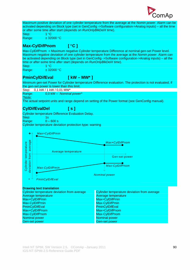
Inteli NT SPtM, SW Version 2.5, ©ComAp –January 2011 IGS-NT-SPtM-2.5-Reference Guide.PDF
90
Maximum positive deviation of one cylinder temperature from the average at the Nomin power. Alarm can be activated depending on Block type (set in GenConfig ->Software configuration->Analog inputs) – all the time or after some time after start (depends on RunOnlyBlkDelX time). Step: 1 °C Range: ± 32000 °C
Max-CylDifPnom [ °C ] Max-CylDifPnom = Maximum negative Cylinder temperature Difference at nominal gen-set Power level. Maximum negative deviation of one cylinder temperature from the average at the Nomin power. Alarm can be activated depending on Block type (set in GenConfig ->Software configuration->Analog inputs) – all the time or after some time after start (depends on RunOnlyBlkDelX time). Step: 1 °C Range: ± 32000 °C
PminCylDifEval [ kW – MW* ] Minimum gen-set Power for Cylinder temperature Difference evaluation. The protection is not evaluated, if the gen-set power is lower than this limit. Step: 0,1 kW / 1 kW / 0,01 MW* Range: 0,0 kW – Nominal power* *Note: The actual setpoint units and range depend on setting of the Power format (see GenConfig manual).
CylDifEvalDel [ s ] Cylinder temperature Difference Evaluation Delay. Step: 1s Range: 0 – 600 s Cylinder temperature deviation protection type: warning
Gen-set power
Cyl
inde
r te
mpe
ratu
rede
viat
ion
from
ave
rage
Max+CylDifPmin
Max-CylDifPmin
Max+CylDifPnom
Nominal powerPminCylDifEval
Max-CylDifPnom
+
-
Average temperature
Drawing text translation Cylinder temperature deviation from average Cylinder temperature deviation from average Average temperature Average temperature Max+CylDifPmin Max+CylDifPmin Max-CylDifPmin Max-CylDifPmin PminCylDifEval PminCylDifEval Max+CylDifPnom Max+CylDifPnom Max-CylDifPnom Max-CylDifPnom Nominal power Nominal power Gen-set power Gen-set power
Inteli NT SPtM, SW Version 2.5, ©ComAp –January 2011 IGS-NT-SPtM-2.5-Reference Guide.PDF
91
Service time 1 [ h ]
Service time 2 [ h ]
Service time 3 [ h ]
Service time 4 [ h ] Running hours down counters are decremented when engine is running. Service alarm is indicated in Alarm list and History record is activated when at least one of the counters reaches zero. Service time X setpoints are actual counter values. Step: 1 h Range: 0 – 65534 h; OFF Hint: Once a service time has elapsed the corresponding Service time X setpoint must be adjusted again to a non-zero value to clear the alarm and begin a new countdown. You can rename the particular timers using Translator in GenConfig to indicate specific service intervals – e.g. “OilChange time”, “SparkPlug time”, ...
Service Time can be switched off if Service Time X = 65535 (OFF).
Analog protect The content depends on programmable protections settings. This list contains pre-set protections from default archives:
Batt >V [ V ] Warning level for battery over voltage. Step: 0,1 V Range: 8,0 – 40,0 V
Batt <V [ V ] Warning level for low battery voltage. Step: 0,1 V Range: 8,0 – 40,0 >V
Batt volt del [ s ] Delay for battery voltage alarms. Step: 1 s Range: 0 – 600,0 s
Gener protect The content depends on programmable protections settings. This list contains pre-set protections from default archives + fixed protections, which are always present:
OverldStrtEval [ % ] (FV) Specifies the overload level, where the protection evaluation starts (see figure at 2PovrldStEvDel). Under this level the protection is not active. Step: 1 % of Nomin power Range: 100 – 200 % Force value possibility: Yes
2POvrldStEvDel [ s ] IDMT curve shape selection. 2PovrldStEvDel is the Reaction time of IDMT protection for 200% overload Pgen = 2* OverldStrtEval. Step: 0,1 s Range: 0,0 - 600,0 s
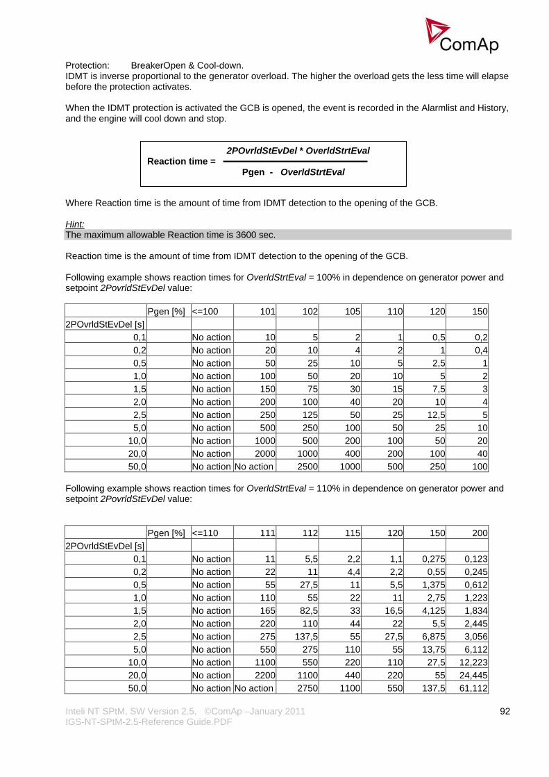
Inteli NT SPtM, SW Version 2.5, ©ComAp –January 2011 IGS-NT-SPtM-2.5-Reference Guide.PDF
92
Protection: BreakerOpen & Cool-down. IDMT is inverse proportional to the generator overload. The higher the overload gets the less time will elapse before the protection activates. When the IDMT protection is activated the GCB is opened, the event is recorded in the Alarmlist and History, and the engine will cool down and stop.
2POvrldStEvDel * OverldStrtEval Reaction time = Pgen - OverldStrtEval
Where Reaction time is the amount of time from IDMT detection to the opening of the GCB.
Hint: The maximum allowable Reaction time is 3600 sec. Reaction time is the amount of time from IDMT detection to the opening of the GCB. Following example shows reaction times for OverldStrtEval = 100% in dependence on generator power and setpoint 2PovrldStEvDel value: Pgen [%] <=100 101 102 105 110 120 1502POvrldStEvDel [s]
0,1 No action 10 5 2 1 0,5 0,20,2 No action 20 10 4 2 1 0,40,5 No action 50 25 10 5 2,5 11,0 No action 100 50 20 10 5 21,5 No action 150 75 30 15 7,5 32,0 No action 200 100 40 20 10 42,5 No action 250 125 50 25 12,5 55,0 No action 500 250 100 50 25 10
10,0 No action 1000 500 200 100 50 2020,0 No action 2000 1000 400 200 100 4050,0 No action No action 2500 1000 500 250 100
Following example shows reaction times for OverldStrtEval = 110% in dependence on generator power and setpoint 2PovrldStEvDel value: Pgen [%] <=110 111 112 115 120 150 2002POvrldStEvDel [s]
0,1 No action 11 5,5 2,2 1,1 0,275 0,1230,2 No action 22 11 4,4 2,2 0,55 0,2450,5 No action 55 27,5 11 5,5 1,375 0,6121,0 No action 110 55 22 11 2,75 1,2231,5 No action 165 82,5 33 16,5 4,125 1,8342,0 No action 220 110 44 22 5,5 2,4452,5 No action 275 137,5 55 27,5 6,875 3,0565,0 No action 550 275 110 55 13,75 6,112
10,0 No action 1100 550 220 110 27,5 12,22320,0 No action 2200 1100 440 220 55 24,44550,0 No action No action 2750 1100 550 137,5 61,112

Inteli NT SPtM, SW Version 2.5, ©ComAp –January 2011 IGS-NT-SPtM-2.5-Reference Guide.PDF
93
Pgen
Nominal power
2POvrldStEvDel
Maximal Reaction timeRe
actio
ntim
eOverldStrtEval
Min Power PtM [ % ] (FV) Min Power PtM [ % ] (FV) Minimum Power in Parallel to the Mains is the minimal value of the gen-set power in parallel to the mains. Gen-set is never loaded below this level (even if the active load control loop requests a lower level). There is no indication or alarm when Min Power PtM level is reached.
Minimum Power in Parallel to the Mains is the minimal value of the gen-set power in parallel to the mains. Gen-set is never loaded below this level (even if the active load control loop requests a lower level). There is no indication or alarm when Min Power PtM level is reached. Step: 1 % of Nomin power Step: 1 % of Nomin power Range: 0 – 100 % of Nomin power Range: 0 – 100 % of Nomin power Force value possibility: Yes Force value possibility: Yes Hint:Hint: If the setpoint Base load is lower than setpoint Gener protect: Min power PtM, the gen-set requested load is set to Gener protect: Min power PtM. The value of Min Power PtM is ignored during Warming procedure. The setpoint is used as a limit for Low power protection: if it becomes active, the load is ramped-down using setpoint Sync/Load strl: Load ramp, to Min power PtM. After protection becomes inactive, the power limitation is automatically terminated.
Ishort [ % ] If the level set in this setpoint is reached, the GCB is opened with delay defined in Ishort del. Intended for shortcurrent detection. Step: 1 % of Nomin current Range: 100 - 500 % of Nomin current Protection: BreakerOpen & Cool-down.
Ishort del [ s ] Delay for generator shortcurrent protection. Step: 0,02 s Range: 0,00 – 10,00 s Hint: Ishort del can be set in GenConfig to 0,01 s, but this value is rounded to the proximate controller evaluation period, which is 0,02 s when the frequency is 50Hz.

Inteli NT SPtM, SW Version 2.5, ©ComAp –January 2011 IGS-NT-SPtM-2.5-Reference Guide.PDF
94
2Inom del [ s ] IDMT curve shape selection. 2Inom del is the Reaction time of IDMT protection for 200% overcurrent Igen = 2* Nominal current. Step: 0,1 s Range: 0,0 - 60,0 s Protection: BreakerOpen & Cool-down. IDMT is inversely proportional to the generators overcurrent. The higher the overcurrent gets the less time will elapse before the protection is activated. When the IDMT protection is activated the GCB is opened, the event is recorded in the Alarmlist and History, and the engine will cool down and stop.
Where Reaction time is the amount of time from IDMT detection to the opening of the GCB. Hint: The maximum allowable Reaction time is 900 sec. Reaction time is the amount of time from IDMT detection to the opening of the GCB. Igen is the maximum current of the three phases of generator current. EXAMPLE of Reaction time for different over current levels. Igen [%] <=100 101 102 105 110 120 150 2002Inom del
0,1 No action 10 5 2 1 0,5 0,2 0,10,2 No action 20 10 4 2 1 0,4 0,20,5 No action 50 25 10 5 2,5 1 0,51,0 No action 100 50 20 10 5 2 12,0 No action 200 100 40 20 10 4 25,0 No action 500 250 100 50 25 10 5
10,0 No action No action 500 200 100 50 20 1020,0 No action No action No action 400 200 100 40 2050,0 No action No action No action No action 500 250 100 50
!!! VERY IMPORTANT !!!
• The maximum input range of the controller current terminals is 11 Amps. Anything over this value is displayed as measured limit, e.g. 15 Amps from CT is measured and displayed as 11 Amps.
• Take special care when selecting CT’s. All available 5 Amp CT’s do not have a range up to 11 Amps.
2Inom del * Nomin current Reaction time = Igen - Nomin current

Inteli NT SPtM, SW Version 2.5, ©ComAp –January 2011 IGS-NT-SPtM-2.5-Reference Guide.PDF
95
Igen
Nominal current Ishort
2Inom del
Maximal Reaction timeRe
actio
ntim
e
Gen >V BOC [ % ] (FV) Threshold for generator over voltage in % of nominal voltage. Step: 1 % Range: Gen <V BOC – 150 % of GenNomV or GenNomVph-ph respectively Protection: BreakerOpen & Cool-down.
Gen <V BOC [ % ] (FV) Threshold for generator under voltage in % of nominal voltage. Step: 1 % Range: 20 – Gen >V BOC % of GenNomV or GenNomVph-ph respectively Protection: BreakerOpen & Cool-down. Hint: All three phases are checked for generator voltage protection. Minimum or maximum out of three is used.
Gen >V Sd [ % ] (FV) 2nd threshold for generator over voltage in % of nominal voltage. Step: 1 % Range: 50 – 150 % of GenNomV or GenNomVph-ph respectively Protection: Shutdown.
Gen V del [ s ] Delay for generator under and over voltage protection. Step: 0,02 s Range: 0,00 – 600,00 s
Gen >f [ % ] (FV) Threshold for generator over frequency in % of nominal frequency. Step: 0,1 % Range: Gen<f – 150,0 % of Nominal freq Protection: BreakerOpen & Cool-down.
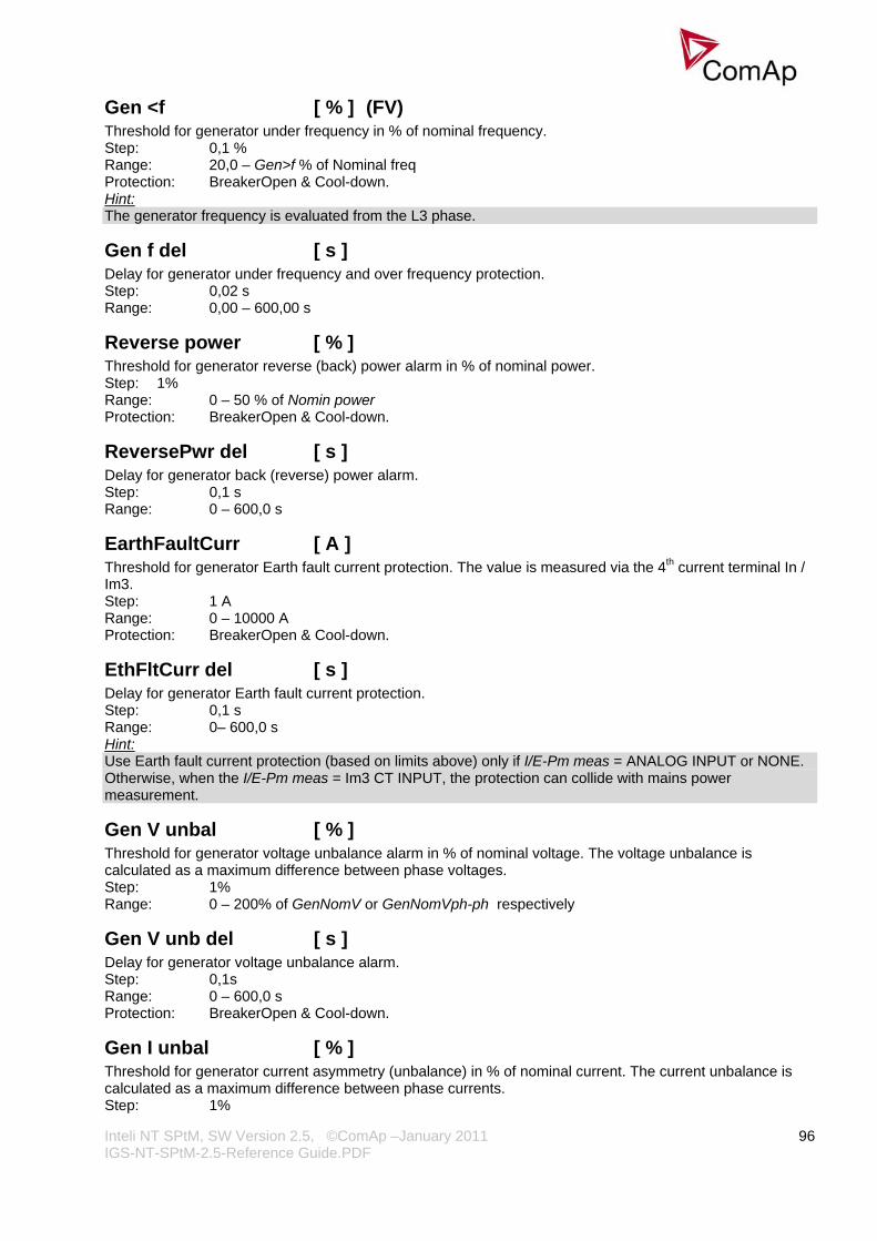
Inteli NT SPtM, SW Version 2.5, ©ComAp –January 2011 IGS-NT-SPtM-2.5-Reference Guide.PDF
96
Gen <f [ % ] (FV) Threshold for generator under frequency in % of nominal frequency. Step: 0,1 % Range: 20,0 – Gen>f % of Nominal freq Protection: BreakerOpen & Cool-down. Hint: The generator frequency is evaluated from the L3 phase.
Gen f del [ s ] Delay for generator under frequency and over frequency protection. Step: 0,02 s Range: 0,00 – 600,00 s
Reverse power [ % ] Threshold for generator reverse (back) power alarm in % of nominal power. Step: 1% Range: 0 – 50 % of Nomin power Protection: BreakerOpen & Cool-down.
ReversePwr del [ s ] Delay for generator back (reverse) power alarm. Step: 0,1 s Range: 0 – 600,0 s
EarthFaultCurr [ A ] Threshold for generator Earth fault current protection. The value is measured via the 4th current terminal In / Im3. Step: 1 A Range: 0 – 10000 A Protection: BreakerOpen & Cool-down.
EthFltCurr del [ s ] Delay for generator Earth fault current protection. Step: 0,1 s Range: 0– 600,0 s Hint: Use Earth fault current protection (based on limits above) only if I/E-Pm meas = ANALOG INPUT or NONE. Otherwise, when the I/E-Pm meas = Im3 CT INPUT, the protection can collide with mains power measurement.
Gen V unbal [ % ] Threshold for generator voltage unbalance alarm in % of nominal voltage. The voltage unbalance is calculated as a maximum difference between phase voltages. Step: 1% Range: 0 – 200% of GenNomV or GenNomVph-ph respectively
Gen V unb del [ s ] Delay for generator voltage unbalance alarm. Step: 0,1s Range: 0 – 600,0 s Protection: BreakerOpen & Cool-down.
Gen I unbal [ % ] Threshold for generator current asymmetry (unbalance) in % of nominal current. The current unbalance is calculated as a maximum difference between phase currents. Step: 1%
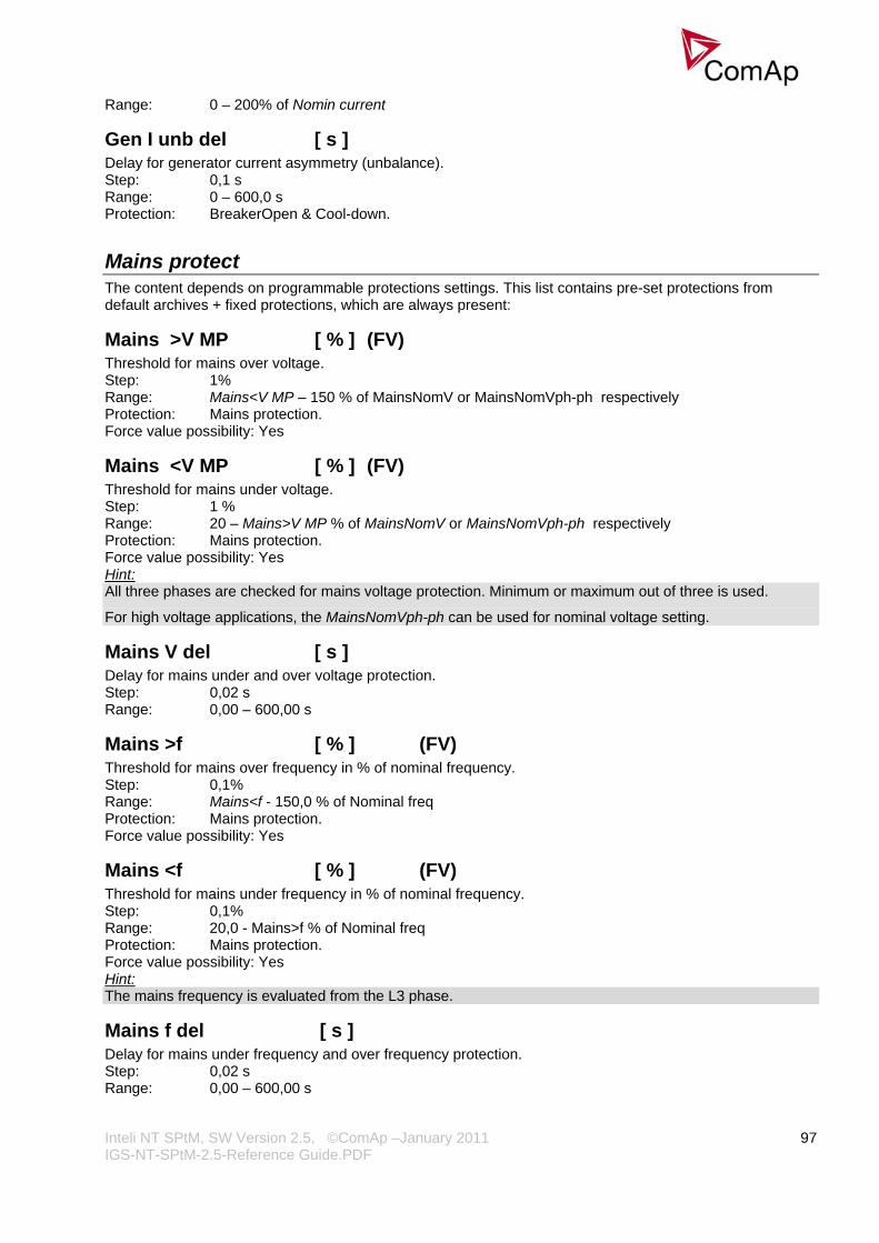
Inteli NT SPtM, SW Version 2.5, ©ComAp –January 2011 IGS-NT-SPtM-2.5-Reference Guide.PDF
97
Range: 0 – 200% of Nomin current
Gen I unb del [ s ] Delay for generator current asymmetry (unbalance). Step: 0,1 s Range: 0 – 600,0 s Protection: BreakerOpen & Cool-down.
Mains protect The content depends on programmable protections settings. This list contains pre-set protections from default archives + fixed protections, which are always present:
Mains >V MP [ % ] (FV) Threshold for mains over voltage. Step: 1% Range: Mains<V MP – 150 % of MainsNomV or MainsNomVph-ph respectively Protection: Mains protection. Force value possibility: Yes
Mains <V MP [ % ] (FV) Threshold for mains under voltage. Step: 1 % Range: 20 – Mains>V MP % of MainsNomV or MainsNomVph-ph respectively Protection: Mains protection. Force value possibility: Yes Hint: All three phases are checked for mains voltage protection. Minimum or maximum out of three is used.
For high voltage applications, the MainsNomVph-ph can be used for nominal voltage setting.
Mains V del [ s ] Delay for mains under and over voltage protection. Step: 0,02 s Range: 0,00 – 600,00 s
Mains >f [ % ] (FV) Threshold for mains over frequency in % of nominal frequency. Step: 0,1% Range: Mains<f - 150,0 % of Nominal freq Protection: Mains protection. Force value possibility: Yes
Mains <f [ % ] (FV) Threshold for mains under frequency in % of nominal frequency. Step: 0,1% Range: 20,0 - Mains>f % of Nominal freq Protection: Mains protection. Force value possibility: Yes Hint: The mains frequency is evaluated from the L3 phase.
Mains f del [ s ] Delay for mains under frequency and over frequency protection. Step: 0,02 s Range: 0,00 – 600,00 s

Inteli NT SPtM, SW Version 2.5, ©ComAp –January 2011 IGS-NT-SPtM-2.5-Reference Guide.PDF
98
VectorS prot [ DISABLED / PARALLEL ONLY / ENABLED ] (FV) DISABLED: Vector shift protection is disabled. PARALLEL ONLY: Vector shift protection is enabled only if the gen-set is running in parallel with mains (=
MCB+GCB status active). ENABLED: Vector shift protection is enabled if MCB status is active. Force value possibility: Yes Hint: If ENABLED is selected, it is likely that Vector shift protection will trip the MCB before other mains protections. It senses the fast changes in mains voltage angle position, which occur with every mains failure, even if the gen-set is not running in parallel with mains.
VectorS CB sel [ MCB / GCB ] (FV) MCB: MCB is tripped if Vector shift protection gets active. GCB: GCB is tripped if Vector shift protection gets active. Force value possibility: Yes Hint: If GCB is selected and mains failure comes up, it is likely that MCB trips as well later on because of other mains protections.
VectorS limit [ ° ] Vector shift protection threshold level. Step: 1° Range: 1 – 45° Hint: To be sure of proper adjusting of VectorS limit, check Max VectorS value on the controller or PC software screen. Max VectorS value is set to zero when transiting to parallel, and then accumulates the maximum reached value (positive only) during parallel operation. Thus, during the normal operation, only the “background noise” is accumulated (usually max 3°), and the protection level should be set to approximately twice the value of this “noise”.
Mains V unbal [ % ] Threshold for mains voltage unbalance alarm in % of nominal voltage. The voltage unbalance is calculated as a maximum difference between phase voltages. Step: 1% Range: 0 – 200% of MainsNomV or MainsNomVph-ph respectively
Mains Vunb del [ s ] Delay for mains voltage unbalance alarm. Step: 0,1s Range: 0 – 600,0 s Protection: Mains protection
AMF settings
EmergStart del [ s ] (FV) Delay between the mains failure and the emergency start of the gen-set. Step: 1 s Range: 0 – 600 s Force value possibility: Yes
FwRet break [ s ] (FV) Delay between GCB opening and MCB closing during the return to mains when reverse synchronizing is not enabled. Delay between MCB opening and GCB closing in TEST Mode, when Return To mains = ENABLED and power cut comes. Step: 0,1 s

Inteli NT SPtM, SW Version 2.5, ©ComAp –January 2011 IGS-NT-SPtM-2.5-Reference Guide.PDF
99
Range: 0 – 60,0 s Force value possibility: Yes Hint: Gen-set is not started automatic in AUT when Mains params OK = 1 nad forward synchronization is not allowed.
MCB close del [ s ] (FV) Delay after mains return to MCB closing, if gen-set is not running. Step: 0,1 s Range: 0 – 60,0 s Force value possibility: Yes
MCB opens on [ MAINSFAIL / GEN RUNNING ] (FV) Adjusting of condition when MCB opens after Mains fail: MAINSFAIL: Controller opens the MCB when Mains fail is detected (24 VDC controlled circuit breaker or contactor expected). GEN RUNNING:Controller opens the MCB only after the gen-set start, i.e. the generator voltage is present to
open the MCB (230 VAC controlled breaker expected). In OFF mode, this means MCB stays closed all the time, regardless of the mains condition.
Force value possibility: Yes
ReturnWithIntr [ ENABLED / DISABLED ] (FV) ENABLED: Enables break transfer of the load back to the mains if reverse synchronizing is not
successful = opens GCB and after FwRet break delay closes MCB. DISABLED: Gen-set stays running loaded in island when reverse synchronizing is not successful, even if
mains is OK again. Force value possibility: Yes
BreakerOverlap [ s ] (FV) When limited time of running in parallel with mains is required, BreakerOverlap defines max time of running in parallel with mains. During this time soft transfer of load is activated. Used in AUT and TEST modes. Step: 0,1 s Range: 0,0 – 300,0 s Force value possibility: Yes Hint: Breaker overlap is taken into account only when no Mains Import is measured and MCB can be open immediately.
Ret fromIsland [ MANUAL / AUTO ] (FV) The setpoint selects the behavior of the controller in the moment the GCB is closed to a dead bus (i.e. transition to the island operation). MANUAL: The controller is always switched automatically from AUT or TEST to MAN mode when the
GCB is closed to a dead bus. That means the controller will then continue supplying the load even if the mains is already restored. The transfer of the load back to the mains must be initiated manually by switching to AUT again or using the panel buttons.
AUTO: The controller remains in AUT or TEST mode and the transfer of the load back to the mains is initiated automatically with delay adjusted by the setpoint Mains ret del.
Hint: Select Ret fromIsland = MANUAL when it is important at what time the load is transferred back to the mains. Force value possibility: Yes
ReturnTo mains [ DISABLED / ENABLED ] (FV) The setpoint influences the behavior of the TEST mode. If mains fail occurs during test (or is simulated using Test on load function), the controller opens the MCB and switches the load to generator. DISABLED: Now if the mains recovers, the generator stays running loaded until TEST mode is
abandoned, typically to AUT mode where reverse synchronizing and generator soft unloading follows.
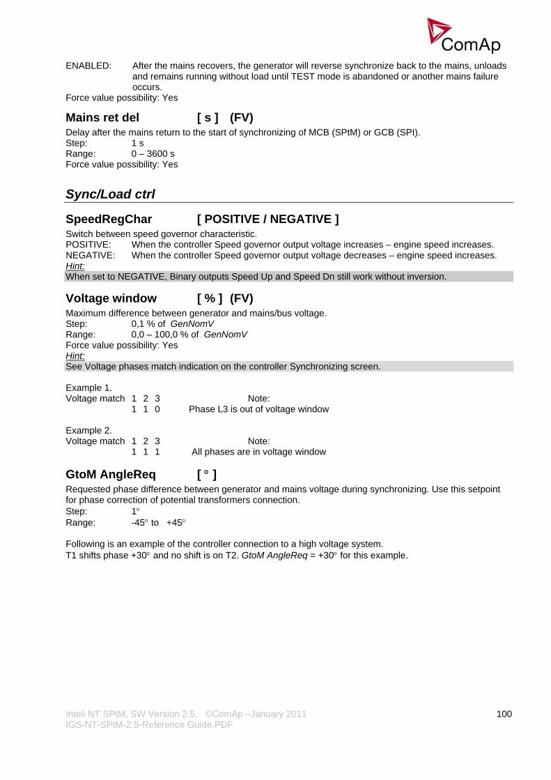
Inteli NT SPtM, SW Version 2.5, ©ComAp –January 2011 IGS-NT-SPtM-2.5-Reference Guide.PDF
100
ENABLED: After the mains recovers, the generator will reverse synchronize back to the mains, unloads and remains running without load until TEST mode is abandoned or another mains failure occurs.
Force value possibility: Yes
Mains ret del [ s ] (FV) Delay after the mains return to the start of synchronizing of MCB (SPtM) or GCB (SPI). Step: 1 s Range: 0 – 3600 s Force value possibility: Yes
Sync/Load ctrl
SpeedRegChar [ POSITIVE / NEGATIVE ] Switch between speed governor characteristic. POSITIVE: When the controller Speed governor output voltage increases – engine speed increases. NEGATIVE: When the controller Speed governor output voltage decreases – engine speed increases. Hint: When set to NEGATIVE, Binary outputs Speed Up and Speed Dn still work without inversion.
Voltage window [ % ] (FV) Maximum difference between generator and mains/bus voltage. Step: 0,1 % of GenNomV Range: 0,0 – 100,0 % of GenNomV Force value possibility: Yes Hint: See Voltage phases match indication on the controller Synchronizing screen. Example 1. Voltage match 1 2 3 Note: 1 1 0 Phase L3 is out of voltage window Example 2. Voltage match 1 2 3 Note: 1 1 1 All phases are in voltage window
GtoM AngleReq [ ° ] Requested phase difference between generator and mains voltage during synchronizing. Use this setpoint for phase correction of potential transformers connection. Step: 1° Range: -45° to +45° Following is an example of the controller connection to a high voltage system. T1 shifts phase +30° and no shift is on T2. GtoM AngleReq = +30° for this example.

Inteli NT SPtM, SW Version 2.5, ©ComAp –January 2011 IGS-NT-SPtM-2.5-Reference Guide.PDF
101
IG/IS-NT
MCB
LOAD
GCB
4
Vm Im MCB GCB
3x10 kV 3x230/400VAC
Vg Ig
L1, L2, L3, NG
4
T1
T2
3
Phase window [ ° ] (FV) Maximum phase angle (mains/bus x generator voltage) ±difference between requested and actual angle for synchronizing. Step: 1° Range: 0° – 90° Force value possibility: Yes Hint: If you want to lock out the GCB (or MCB) closing during synchronizing loop test, set Phase window = 0. This allows the control loop to be tested while actual GCB (or MCB) closing is blocked. If force value function is used with this setpoint, it is strongly recommended to use only another setpoint as the source of an alternative value (preferably from group Force value). Measured values are not optimal for this purpose.
Dwell time [ s ] (FV) The period of time that the phase angle must be within Phase window and voltage differece within Voltage window before a breaker (GCB/MCB) is closed. Step: 0,1 s Range: 0,0 – 25,0 s Force value possibility: Yes
Freq gain [ % ] Gain of frequency control loop. Step: 0,1 % Range: 0,0 % - 200,0 %
Freq int [ % ] Relative integration factor of frequency control loop. Step: 1 % Range: 0 % – 100 %
Freq reg loop [ ALL THE TIME / SYNC ONLY ] (FV) ALL THE TIME: Frequency control is active in island operation, running unloaded period and synchronizing. SYNC ONLY: Frequency control is active during synchronizing only. Force value possibility: Yes
Angle gain [ % ] Gain of angle control loop. Step: 0,1% Range: 0,0 % to +200,0 %

Inteli NT SPtM, SW Version 2.5, ©ComAp –January 2011 IGS-NT-SPtM-2.5-Reference Guide.PDF
102
Speed gov bias [ V ] (FV) Speed control DC output bias level of SPEED GOVERNOR voltage output. Step: 0,01 V Range: SpeedGovLowLim to SpeedGovHiLim V Force value possibility: Yes
SpdGovPWM rate [ Hz ] Pulse-Width Modulation rate of the Speed Regulator pulse output. Step: 1 Hz Range: 500 – 3000 Hz Hint: This adjusting can be used for some Cummins and CAT engines speed governor interfaces. We recommend to keep the default setting (1200 Hz) for all other speed governor types (coming out through the analog interface +/- 10V).
SpeedGovLowLim [ V ] Low limit for voltage on analog output of Speed Regulator. Step: 0,01 V Range: -10,00 V – SpeedGovHiLim
SpeedGovHiLim [ V ] High limit for voltage on analog output of Speed Regulator. Step: 0,01 V Range: SpeedGovLowLim - 10,00 V
TauSpeedActuat [ s ] Time constant of the speed actuator connected to the binary Up/Down outputs. This is to match the reaction of the controller’s regulator with the actual reaction time of the actuator. Step: 0,1 s Range: 1,0 - 300,0 s
Load ramp [ s ] (FV) Increasing or decreasing load rate. In seconds / Nomin power. Step: 1 s Range: 0 – GCB open del s Force value possibility: Yes Hint: Increasing or decreasing load rate with relation to faster or slower reaching requested value. Usually the Nominal value, BaseLoad or a part of System BaseLoad.
RampStartLevel [ % ] Initial requested load value, on which starts the load ramping according to Load ramp setting in % of nominal load. Step: 1 % Range: 0 – 100 % Hint: In case of higher value of this setpoint and closing the GCB with no load on the mains/bus, an overswing may occur.
Load gain [ % ] Gain of power control loop. Step: 0,1 % Range: 0 – 200,0 %
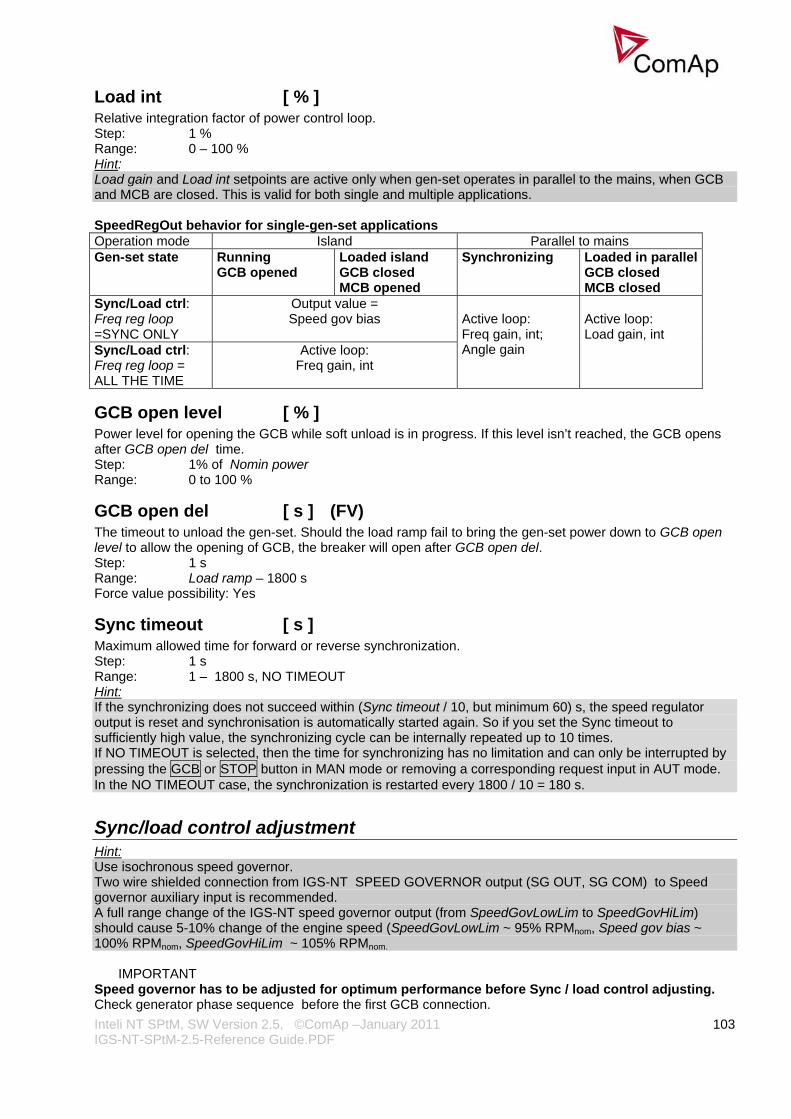
Inteli NT SPtM, SW Version 2.5, ©ComAp –January 2011 IGS-NT-SPtM-2.5-Reference Guide.PDF
103
Load int [ % ] Relative integration factor of power control loop. Step: 1 % Range: 0 – 100 % Hint: Load gain and Load int setpoints are active only when gen-set operates in parallel to the mains, when GCB and MCB are closed. This is valid for both single and multiple applications. SpeedRegOut behavior for single-gen-set applications Operation mode Island Parallel to mains Gen-set state Running
GCB opened Loaded island GCB closed MCB opened
Synchronizing Loaded in parallelGCB closed MCB closed
Sync/Load ctrl: Freq reg loop =SYNC ONLY
Output value = Speed gov bias
Sync/Load ctrl: Freq reg loop = ALL THE TIME
Active loop: Freq gain, int
Active loop: Freq gain, int; Angle gain
Active loop: Load gain, int
GCB open level [ % ] Power level for opening the GCB while soft unload is in progress. If this level isn’t reached, the GCB opens after GCB open del time. Step: 1% of Nomin power Range: 0 to 100 %
GCB open del [ s ] (FV) The timeout to unload the gen-set. Should the load ramp fail to bring the gen-set power down to GCB open level to allow the opening of GCB, the breaker will open after GCB open del. Step: 1 s Range: Load ramp – 1800 s Force value possibility: Yes
Sync timeout [ s ] Maximum allowed time for forward or reverse synchronization. Step: 1 s Range: 1 – 1800 s, NO TIMEOUT Hint: If the synchronizing does not succeed within (Sync timeout / 10, but minimum 60) s, the speed regulator output is reset and synchronisation is automatically started again. So if you set the Sync timeout to sufficiently high value, the synchronizing cycle can be internally repeated up to 10 times. If NO TIMEOUT is selected, then the time for synchronizing has no limitation and can only be interrupted by pressing the GCB or STOP button in MAN mode or removing a corresponding request input in AUT mode. In the NO TIMEOUT case, the synchronization is restarted every 1800 / 10 = 180 s.
Sync/load control adjustment Hint: Use isochronous speed governor. Two wire shielded connection from IGS-NT SPEED GOVERNOR output (SG OUT, SG COM) to Speed governor auxiliary input is recommended. A full range change of the IGS-NT speed governor output (from SpeedGovLowLim to SpeedGovHiLim) should cause 5-10% change of the engine speed (SpeedGovLowLim ~ 95% RPMnom, Speed gov bias ~ 100% RPMnom, SpeedGovHiLim ~ 105% RPMnom.
IMPORTANT
Speed governor has to be adjusted for optimum performance before Sync / load control adjusting. Check generator phase sequence before the first GCB connection.
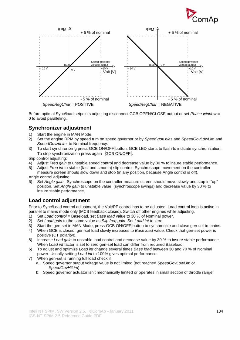
Inteli NT SPtM, SW Version 2.5, ©ComAp –January 2011 IGS-NT-SPtM-2.5-Reference Guide.PDF
104
RPMRPM
Volt [V] Volt [V]0 V +10 V- 10 V
Speed governorvoltage output1500 0 V
- 10 V1500
+10 V
Speed governorvoltage output
+ 5 % of nominal+ 5 % of nominal
- 5 % of nominal - 5 % of nominal SpeedRegChar = POSITIVE SpeedRegChar = NEGATIVE
Before optimal Sync/load setpoints adjusting disconnect GCB OPEN/CLOSE output or set Phase window = 0 to avoid paralleling.
Synchronizer adjustment 1) Start the engine in MAN Mode. 2) Set the engine RPM by speed trim on speed governor or by Speed gov bias and SpeedGovLowLim and
SpeedGovHiLim to Nominal frequency. 3) To start synchronizing press GCB ON/OFF button. GCB LED starts to flash to indicate synchronization.
To stop synchronization press again GCB ON/OFF . Slip control adjusting: 4) Adjust Freq gain to unstable speed control and decrease value by 30 % to insure stable performance. 5) Adjust Freq int to stable (fast and smooth) slip control. Synchroscope movement on the controller
measure screen should slow down and stop (in any position, because Angle control is off). Angle control adjusting: 6) Set Angle gain. Synchroscope on the controller measure screen should move slowly and stop in “up“
position. Set Angle gain to unstable value (synchroscope swings) and decrease value by 30 % to insure stable performance.
Load control adjustment Prior to Sync/Load control adjustment, the Volt/PF control has to be adjusted! Load control loop is active in parallel to mains mode only (MCB feedback closed). Switch off other engines while adjusting. 1) Set Load control = Baseload, set Base load value to 30 % of Nominal power. 2) Set Load gain to the same value as Slip freq gain. Set Load int to zero. 3) Start the gen-set in MAN Mode, press GCB ON/OFF button to synchronize and close gen-set to mains. 4) When GCB is closed, gen-set load slowly increases to Base load value. Check that gen-set power is
positive (CT polarity!). 5) Increase Load gain to unstable load control and decrease value by 30 % to insure stable performance.
When Load int factor is set to zero gen-set load can differ from required Baseload. 6) To adjust and optimize Load int change several times Base load between 30 and 70 % of Nominal
power. Usually setting Load int to 100% gives optimal performance. 7) When gen-set is running full load check if
a. Speed governor output voltage value is not limited (not reached SpeedGovLowLim or SpeedGovHiLim)
b. Speed governor actuator isn’t mechanically limited or operates in small section of throttle range.

Inteli NT SPtM, SW Version 2.5, ©ComAp –January 2011 IGS-NT-SPtM-2.5-Reference Guide.PDF
105
Active and reactive power terminology
MAINS GEN
LOAD
MAINS LOAD GEN P > 0 Import P > 0 Consumption P> 0 Generation Q> 0 Import Q> 0 Consumption Q> 0 Generation
Cos > 0 C Consumption P Capacitive LOAD
Cos > 0 L Consumption P Inductive LOAD
P
Q
Cos < 0 L Export P Import Q
Cos < 0 C Export P Export Q
Cos > 0 C Import P Export Q
Cos > 0 L Import P Import Q
P
Q
Cos < 0 L Consumption P Generation Q
Cos < 0 C Consumption P Consumption Q
Cos > 0 C Generation P Consumption Q
Cos > 0 L Generation P Generation Q
P
Q
Mains Exported active power is supplied to the mains. It is displayed in negative numbers e.g. –20kW. Imported active power is consumed from the mains. It is displayed in positive numbers e.g. +20kW. When reactive power is imported (>0) InteliMains-NT displays L (inductive) character of the load. When reactive power is exported (<0) InteliMains-NT displays C (capacitive) character of the load.
Load Active power consumed by Load is displayed in positive numbers e.g. 20kW. When reactive power is positive (>0) InteliMains-NT displays L (inductive) character of the load. When reactive power is negative (<0) InteliMains-NT displays C (capacitive) character of the load.
Genset Generated active power is displayed in positive numbers e.g. 20kW. When reactive power is positive (>0) IGS-NT displays L (inductive) character of the load. When reactive power is negative (<0) IGS-NT displays C (capacitive) character of the load.

Inteli NT SPtM, SW Version 2.5, ©ComAp –January 2011 IGS-NT-SPtM-2.5-Reference Guide.PDF
106
Volt/PF ctrl
AVRRegChar [ POSITIVE / NEGATIVE ] Switch between AVR characteristic. POSITIVE: When the controller and AVRi output voltage increases – generator voltage increases. NEGATIVE: When the controller and AVRi output voltage decreases – generator voltage increases. Hint: When set to NEGATIVE, Binary outputs AVR Up and AVR Dn still work without inversion.
Voltage gain [ % ] Gain of voltage control loop. Step: 0,1 % Range: 0,0 to +200,0 %
Voltage int [ % ] Relative integration factor of voltage control loop. Increasing of integration value causes quicker response. Step: 1 % Range: 0 – 100 % Hint: Voltage gain and Voltage int setpoints are active (adjust AVR) when GCB is open to maintain the Nominal voltage or to match voltage during synchronizing. Voltage loop operates as well in single island operation.
PF gain [ % ] Gain of power factor control loop. Step: 0,1 % Range: 0,0 – 200,0 %
PF int [ % ] Relative integration factor of power factor control loop. Increasing of integration value causes quicker response. Step: 1 % Range: 0 – 100 % Hint: When any gain setpoint is set to zero, the corresponding control loop is switched OFF. PF gain and PF int setpoints are active only when the gen-set runs parallel to mains. VoltRegOut behavior in single-gen-set applications Operation mode Island Parallel to mains Gen-set state Running,
GCB opened Loaded island GCB closed MCB opened
Synchronizing Loaded in parallelGCB closed
Active loop: Volt gain, int;
Active loop: Volt gain, int;
Active loop: Volt gain, int;
Active loop: PF control
AVR DCout bias [ % ] (FV) AVRi voltage output bias level. This is a basic voltage level of the output if there is no regulation loop active. Step: 0,1 % Range: 0 – 100,0 % Force value possibility: Yes Hint: Real voltage level depends on AVRi outputs connection and output level potentiometer setting. Maximum range is ± 10 V.
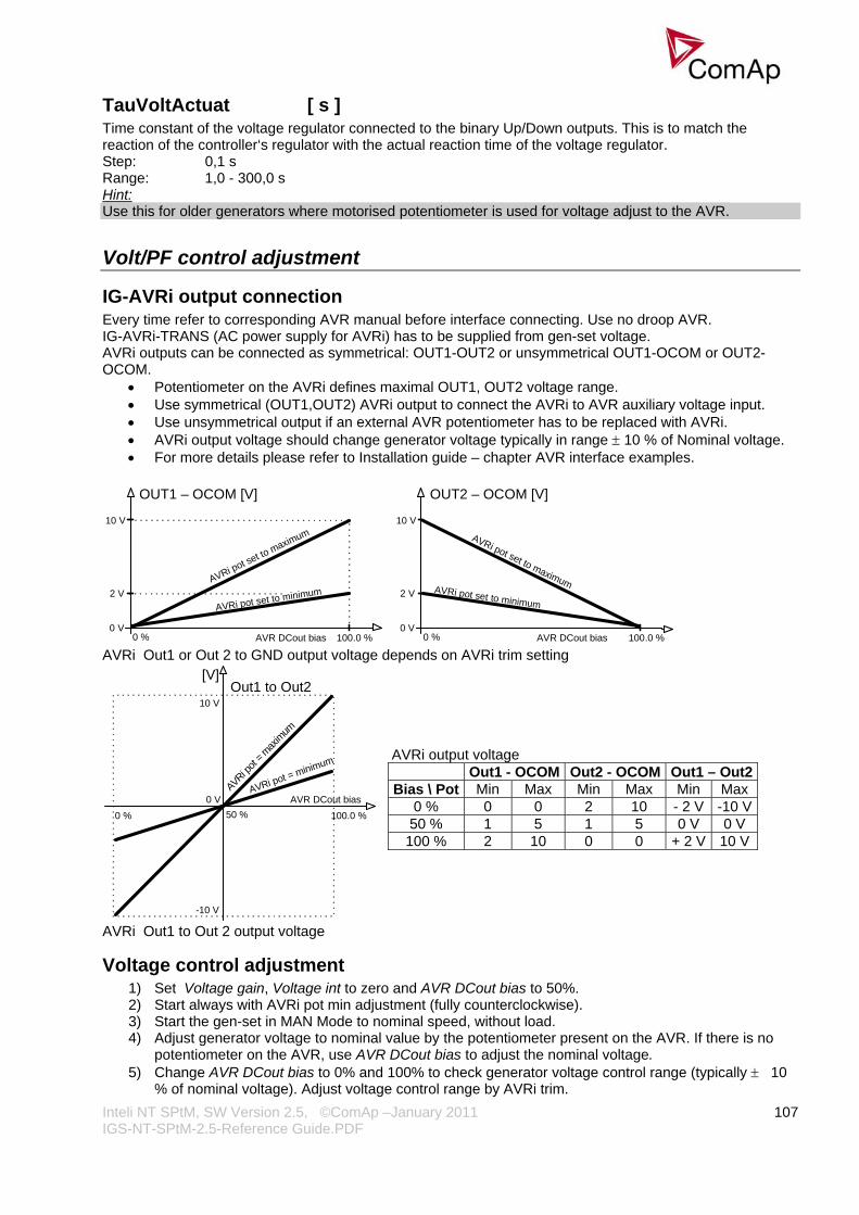
Inteli NT SPtM, SW Version 2.5, ©ComAp –January 2011 IGS-NT-SPtM-2.5-Reference Guide.PDF
107
TauVoltActuat [ s ] Time constant of the voltage regulator connected to the binary Up/Down outputs. This is to match the reaction of the controller‘s regulator with the actual reaction time of the voltage regulator. Step: 0,1 s Range: 1,0 - 300,0 s Hint: Use this for older generators where motorised potentiometer is used for voltage adjust to the AVR.
Volt/PF control adjustment
IG-AVRi output connection Every time refer to corresponding AVR manual before interface connecting. Use no droop AVR. IG-AVRi-TRANS (AC power supply for AVRi) has to be supplied from gen-set voltage. AVRi outputs can be connected as symmetrical: OUT1-OUT2 or unsymmetrical OUT1-OCOM or OUT2-OCOM.
• Potentiometer on the AVRi defines maximal OUT1, OUT2 voltage range. • Use symmetrical (OUT1,OUT2) AVRi output to connect the AVRi to AVR auxiliary voltage input. • Use unsymmetrical output if an external AVR potentiometer has to be replaced with AVRi. • AVRi output voltage should change generator voltage typically in range ± 10 % of Nominal voltage. • For more details please refer to Installation guide – chapter AVR interface examples.
100.0 %
10 V
0 VAVR DCout bias0 %
AVRi pot set to minimum2 VAVRi pot set to maximum
OUT1 – OCOM [V]
100.0 %
10 V
0 VAVR DCout bias0 %
AVRi pot set to minimum2 V
AVRi pot set to maximum
OUT2 – OCOM [V]
AVRi Out1 or Out 2 to GND output voltage depends on AVRi trim setting
[V]
100.0 %
AVRi pot
=maxim
um
AVR DCout bias
10 VOut1 to Out2
0 V0 %
-10 V
AVRi pot = minimum
50 %
AVRi output voltage Out1 - OCOM Out2 - OCOM Out1 – Out2Bias \ Pot Min Max Min Max Min Max
0 % 0 0 2 10 - 2 V -10 V50 % 1 5 1 5 0 V 0 V
100 % 2 10 0 0 + 2 V 10 V
AVRi Out1 to Out 2 output voltage
Voltage control adjustment 1) Set Voltage gain, Voltage int to zero and AVR DCout bias to 50%. 2) Start always with AVRi pot min adjustment (fully counterclockwise). 3) Start the gen-set in MAN Mode to nominal speed, without load. 4) Adjust generator voltage to nominal value by the potentiometer present on the AVR. If there is no
potentiometer on the AVR, use AVR DCout bias to adjust the nominal voltage. 5) Change AVR DCout bias to 0% and 100% to check generator voltage control range (typically ± 10
% of nominal voltage). Adjust voltage control range by AVRi trim.

Inteli NT SPtM, SW Version 2.5, ©ComAp –January 2011 IGS-NT-SPtM-2.5-Reference Guide.PDF
108
6) Set AVR DCout bias to be Nominal voltage on generator (50%). 7) When gen-set is running unloaded increase carefully Voltage gain to unstable point and then
decrease value by 30 % to insure stable performance. 8) Adjust Voltage int (usually setting to 100% gives optimal performance).
Hint: To judge optimal adjusting induce generator voltage jumps by AVR DCout bias change or by Nominal voltage change . AVRi output OCOM is common output. GND was used instead of OCOM
PF control adjustment The genset should be cca 30 % loaded in parallel to mains and baseload mode. 1) Set the same values PF gain, PF int as in voltage control loop. 2) Set Process control: Load ctrl PtM = BASELOAD, Base load = 30 % of Nominal load, PF ctrl PtM
= BASEPF, Base PF = 1.0. 3) Start and synchronize the gen-set in MAN Mode by pressing GCB ON/OFF 4) When running in parallel 30% loaded increase slowly PF gain to unstable point and then decrease
value by 30 % to insure stable performance. 5) Adjust PF int (usually setting to 100% gives optimal performance). Hint: To judge optimal adjusting induce generator power jumps by Base load change or by soft changes of AVR DCout bias.
Force value
Force value 1-16 [ X ] „Source“ setpoints containing the alternative values for selected „target“ setpoints. The setpoint with index X corresponds to the ForceValueInXXth function. Hint: As the “source” for Force value channel can be used any compatible value in the controller (in general all values and setpoints of types integer8,16,32). In that case the corresponding ForceValueInXX setpoint is unused on that channel.
ExtValue1LoLim [ X ]
ExtValue2LoLim [ X ]
ExtValue3LoLim [ X ]
ExtValue4LoLim [ X ] ExtValueX low limit. The value is not decreased under this limit, even if the request still exists (via binary input ExtValueX down). Step: 1 X Range: -32000 – ExtValueXHiLim X
ExtValue1HiLim [ X ]
ExtValue2HiLim [ X ]
ExtValue3HiLim [ X ]
ExtValue4HiLim [ X ] ExtValueX high limit. The value is not increased above this limit, even if the request still exists (via binary input ExtValueX up). Step: 1 X

Inteli NT SPtM, SW Version 2.5, ©ComAp –January 2011 IGS-NT-SPtM-2.5-Reference Guide.PDF
109
Range: ExtValueXLoLim – 32000 X
ExtValue1 rate [ X/s ] (FV)
ExtValue2 rate [ X/s ] (FV)
ExtValue3 rate [ X/s ] (FV)
ExtValue4 rate [ X/s ] (FV) ExtValueX rate of change per second. If the binary input ExtValueX down or ExtValueX up is active, the value is changed according to this rate. Step: 1 X/s Range: 1 – 10000 X/s Hint: If binary input ExtValueXreset is active, the corresponding ExtValueX is held at its default value, regardless of the activity of inputs Up and Down and regardless of incoming external set commands. Using this function in combination with Force value you can externally control selected setpoints’ values and achieve some special behaviour of the controller.
ExtValue1deflt [ X ] (FV)
ExtValue2deflt [ X ] (FV)
ExtValue3deflt [ X ] (FV)
ExtValue4deflt [ X ] (FV) ExtValueX default (starting) value. If ExtValueX is changed from this default value using Modbus command, the new value is kept in ExtValueX until another command arrives or until the controller has been switched off. If the binary input ExtValueXreset is active, the ExtValueX is held at this value regardless of other conditions. Step: 1 X Range: -32000 – 32000 X
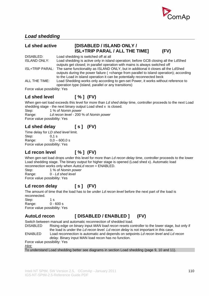
Inteli NT SPtM, SW Version 2.5, ©ComAp –January 2011 IGS-NT-SPtM-2.5-Reference Guide.PDF
110
Load shedding
Ld shed active [DISABLED / ISLAND ONLY / ISL+TRIP PARAL / ALL THE TIME] (FV) DISABLED: Load shedding is switched off at all ISLAND ONLY: Load shedding is active only in island operation; before GCB closing all the LdShed
outputs get closed; in parallel operation with mains is always switched off ISL+TRIP PARAL: The same functionality as ISLAND ONLY, but in additional it closes all the LdShed
outputs during the power failure ( =change from parallel to island operation); according to the Load in island operation it can be potentially reconnected beck
ALL THE TIME: Load Shedding works only according to gen-set Power, it works without reference to operation type (island, parallel or any transitions)
Force value possibility: Yes
Ld shed level [ % ] (FV) When gen-set load exceeds this level for more than Ld shed delay time, controller proceeds to the next Load shedding stage - the next binary output Load shed x is closed. Step: 1 % of Nomin power Range: Ld recon level - 200 % of Nomin power Force value possibility: Yes
Ld shed delay [ s ] (FV) Time delay for LD shed level limit. Step: 0,1 s Range: 0,0 – 600,0 s Force value possibility: Yes
Ld recon level [ % ] (FV) When gen-set load drops under this level for more than Ld recon delay time, controller proceeds to the lower Load shedding stage. The binary output for higher stage is opened (Load shed x). Automatic load reconnection works only when AutoLd recon = ENABLED. Step: 1 % of Nomin power Range: 0 - Ld shed level Force value possibility: Yes
Ld recon delay [ s ] (FV) The amount of time that the load has to be under Ld recon level before the next part of the load is reconnected. Step: 1 s Range: 0 - 600 s Force value possibility: Yes
AutoLd recon [ DISABLED / ENABLED ] (FV) Switch between manual and automatic reconnection of shedded load. DISABLED Rising edge on binary input MAN load recon resets controller to the lower stage, but only if
the load is under the Ld recon level. Ld recon delay is not important in this case. ENABLED Load reconnection is automatic and depends on setpoints Ld recon level and Ld recon
delay. Binary input MAN load recon has no function. Force value possibility: Yes Hint: To understand Load shedding better see diagrams in section Load shedding (page 9, 10 and 11).

Inteli NT SPtM, SW Version 2.5, ©ComAp –January 2011 IGS-NT-SPtM-2.5-Reference Guide.PDF
111
PLC settings The content depends on actual PLC configuration. Contains all setpoints related to the configurable PLC blocks. If this setpoint group is empty, it is not displayed.
Timer settings
Timer channel 1-16 Defines the setting of particular timer channel. There is 16 channels, each defines occurrence date and time (year, month, day, hour, minute), duration time (in minutes, maximum is 24*60), repeating period (day, week, month, once). In case of week – day of the week selection, when should be executed + selection of repeating (every 1st, 2nd, 3rd or 4th week); In case of month – day of the month selection (e.g. every 3rd day or every 2nd Monday)
Every channel can be disabled by blocking input. If blocking input is active then the timer is not activated even if it should be, according to it’s other settings. The channels are divided into groups of 4. Each group has independent binary output, which activates if any of the 4 channels within the group is active (1-4, 5-8,...), see the picture below. There is also one common output for all 16 channels.
Hint: Timer channel 1-16 can be set via Pc software only. See Reference guide for GenConfig.
Act. calls/SMS
History record [ DISABLED / ENABLED ] (FV) Enables or disables active calls/SMS/mails to selected phone, mobile or mail address when a History record type “protection” occurs. Force value possibility: Yes Hint: If enabled for an SMS type active call, an empty Alarmlist is sent, as this type of protection does not appear there.
Alarm only [ DISABLED / ENABLED ] (FV) Enables or disables active calls/SMS/mails to selected phone, mobile or mail address when an Alarm only type protection occurs. Force value possibility: Yes

Inteli NT SPtM, SW Version 2.5, ©ComAp –January 2011 IGS-NT-SPtM-2.5-Reference Guide.PDF
112
Warning [ DISABLED / ENABLED ] (FV) Enables or disables active calls/SMS/mails to selected phone, mobile or mail address when a Warning type protection occurs. Force value possibility: Yes
Off load [ DISABLED / ENABLED ] (FV) Enables or disables active calls/SMS/mails to selected phone, mobile or mail address when an Off load type protection occurs. Force value possibility: Yes Hint: If enabled for an SMS type active call, an empty Alarmlist is sent, as this type of protection does not appear there.
BrkOpen&CoolDn [ DISABLED / ENABLED ] (FV) Enables or disables active calls/SMS/mails to selected phone, mobile or mail address when a BrkOpen&CoolDn type protection occurs. Force value possibility: Yes
Mains protect [ DISABLED / ENABLED ] (FV) Enables or disables active calls/SMS/mails to selected phone, mobile or mail address when a Mains protect type protection occurs. Force value possibility: Yes Hint: If enabled for an SMS type active call, an empty Alarmlist is sent, as this type of protection does not appear there. AL indication could be used to announced mains fails and based on that SMS could be send.
Slow stop [ DISABLED / ENABLED ] (FV) Enables or disables active calls/SMS/mails to selected phone, mobile or mail address when a Slow stop type protection occurs. Force value possibility: Yes
Shutdown [ DISABLED / ENABLED ] (FV) Enables or disables active calls/SMS/mails to selected phone, mobile or mail address when a Shutdown type protection occurs. Force value possibility: Yes
AcallCH1..3-Type Up to three separate channels are available for any of the following types of messages: DISABLED: Channel is disabled. DATA-ANA: Standard analog modem connection to monitoring SW. DATA-GSM: Standard GSM modem connection to monitoring SW. DATA-ISDN: Standard ISDN modem connection to monitoring SW. DATA-CDMA: CDMA modem connection to monitoring SW. SMS-GSM: Channel sends SMS message via GSM network. Only with GSM modem connected. SMS-CDMA: Channel sends SMS message via CDMA network. Only with CDMA modem connected. IB-E-MAIL: Channel sends E-mail. Only when IG-IB connected. IB-EML-SMS: Channel sends E-mail in short format (SMS). Only when IG-IB connected. Force value possibility: Yes An Email contains
- header with serial number and application info - Alarm list contents - latest 20 History records (reason, date, time)
Example of EML-SMS: AL=(Sd Water Temp,Wrn Water Temp,!Emerg Stop,ActCallCH1Fail)
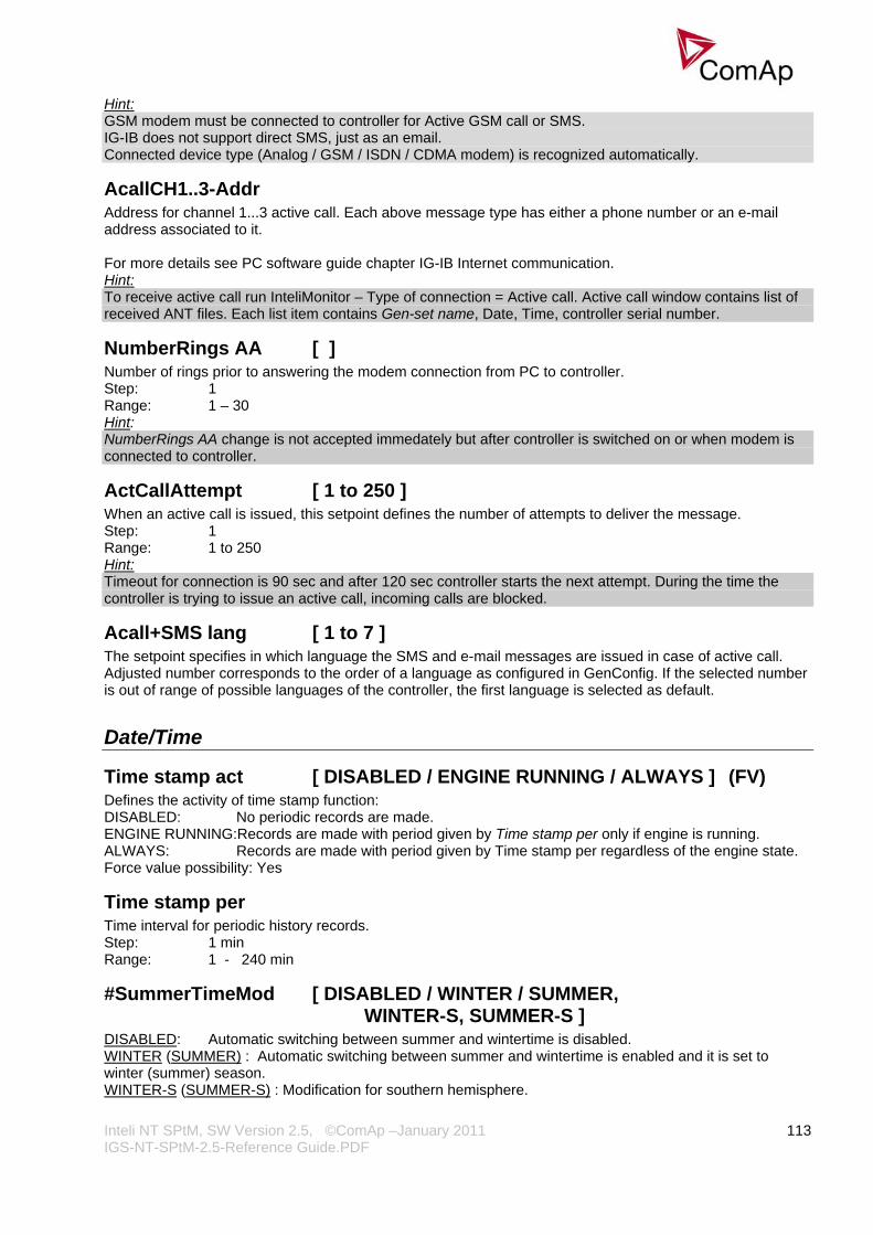
Inteli NT SPtM, SW Version 2.5, ©ComAp –January 2011 IGS-NT-SPtM-2.5-Reference Guide.PDF
113
Hint: GSM modem must be connected to controller for Active GSM call or SMS. IG-IB does not support direct SMS, just as an email. Connected device type (Analog / GSM / ISDN / CDMA modem) is recognized automatically.
AcallCH1..3-Addr Address for channel 1...3 active call. Each above message type has either a phone number or an e-mail address associated to it. For more details see PC software guide chapter IG-IB Internet communication. Hint: To receive active call run InteliMonitor – Type of connection = Active call. Active call window contains list of received ANT files. Each list item contains Gen-set name, Date, Time, controller serial number.
NumberRings AA [ ] Number of rings prior to answering the modem connection from PC to controller. Step: 1 Range: 1 – 30 Hint: NumberRings AA change is not accepted immedately but after controller is switched on or when modem is connected to controller.
ActCallAttempt [ 1 to 250 ] When an active call is issued, this setpoint defines the number of attempts to deliver the message. Step: 1 Range: 1 to 250 Hint: Timeout for connection is 90 sec and after 120 sec controller starts the next attempt. During the time the controller is trying to issue an active call, incoming calls are blocked.
Acall+SMS lang [ 1 to 7 ] The setpoint specifies in which language the SMS and e-mail messages are issued in case of active call. Adjusted number corresponds to the order of a language as configured in GenConfig. If the selected number is out of range of possible languages of the controller, the first language is selected as default.
Date/Time
Time stamp act [ DISABLED / ENGINE RUNNING / ALWAYS ] (FV) Defines the activity of time stamp function: DISABLED: No periodic records are made. ENGINE RUNNING:Records are made with period given by Time stamp per only if engine is running. ALWAYS: Records are made with period given by Time stamp per regardless of the engine state. Force value possibility: Yes
Time stamp per Time interval for periodic history records. Step: 1 min Range: 1 - 240 min
#SummerTimeMod [ DISABLED / WINTER / SUMMER, WINTER-S, SUMMER-S ] DISABLED: Automatic switching between summer and wintertime is disabled. WINTER (SUMMER) : Automatic switching between summer and wintertime is enabled and it is set to winter (summer) season. WINTER-S (SUMMER-S) : Modification for southern hemisphere.

Inteli NT SPtM, SW Version 2.5, ©ComAp –January 2011 IGS-NT-SPtM-2.5-Reference Guide.PDF
114
Hint: Summer time is changed according to the last Sunday in March and the time change is executed at 2 a.m. and it is set to 3 a.m. Winter time change is done in the last Sunday in the October and from 3 a.m. is exchanged to 2 a.m..
#Time [HHMMSS] Real time clock adjustment.
#Date [DDMMYYYY] Actual date adjustment. Hint: #Time and #Date setpoints are synchronized via CAN bus each hour with the lowest address controller. #Time or #Date change in any controller changes Time or Date in all controllers on CAN bus.

Inteli NT SPtM, SW Version 2.5, ©ComAp –January 2011 IGS-NT-SPtM-2.5-Reference Guide.PDF
115
List of possible events The complete list is available in Troubleshooting guide.

Inteli NT SPtM, SW Version 2.5, ©ComAp –January 2011 IGS-NT-SPtM-2.5-Reference Guide.PDF
116
Controller configuration and monitoring IGS-NT istallation pack contains separate PC software tools: GenConfig (GC) and InteliMonitor (IM). GC and IM are based on Windows 95/98/NT/ME/2000/XP or higher platform and require approximately 30 Mbyte of hard disc free space.
Direct connection to the PC IGS-NT controller can be connected directly with PC via RS232 or USB interface. Use the crossed RS232 or USB cable to connect PC with controller. Hint: Make sure the grounding system on controller and PC – COM port (negative of the PC DC supply) are identical – before the first direct connection. There must not be any voltage between these two points otherwise the internal PTC protection activates and interrupts RS232 communication. In such case disconnect RS232 line wait a minute for PTC recovery and try again. The simple solution is to assure, that the PC supply 240/20V is ground free (GND terminal is not connected).
5 - GND
2 - RxD3 - TxD
PC
5 - GND
2 - RxD3 - TxD
RS2
32
RS2
32
230 VAC
0 VD
C
CONTROLLER
+-Battery
Required the samevoltage potentialbetween GND‘s
RS 232
GenConfig functions • Extension modules addressing • All I/O function or protection configuration • Setpoints adjusting • Sensor characteristics modification • History record modification • Password level protection modification (password value must be changed in DriveMonitor) • Controller firmware (mhx file) upgrade • Controller application file Up/Down load • Language translator enables
o Create Dictionary between two languages (Dictionary can be used repeatedly) o Translate current text in Controller (in any language) o Add new language (up to five)
Configuration steps Following configuration steps are available in GenConfig software: • Select Extension modules when more inputs and outputs are required • Configure J1939 interface when Electronic engine is connected • Configure Binary inputs as Protection or Function • Configure Binary outputs • Configure Analog inputs as Protection or Function • Define user sensors • Configure History record • Configure password protection • Add/Translate the language
Inteli NT SPtM, SW Version 2.5, ©ComAp –January 2011 IGS-NT-SPtM-2.5-Reference Guide.PDF
117
InteliMonitor
Functions • On-line direct, Modem or Internet single or multiple engine monitoring • Active Modem or Internet call from the controller to PC (activated by selected Alarm) • On-line or Off-line History record listing • Setpoints listing and adjusting (password protected) • Statistics value (e.g. Running hours) Set/Reset • Password and Access code change
Modbus protocol Standard protocol enables receive/transmit any data or command from a Master system: • Direct connection: RS232, RS422, RS485 • Modem connection • 9600, 19200, 38400 or 57600 bps, 8 data bits, 1 stop bit, no parity • Transfer mode RTU • Function 3 (Read Multiply Registers) • Function 6 (Write Single Register) • Function 16 (Write Multiply Registers) • The response to an incoming message depends on the communication speed. The delay is not shorter
than the time needed to send/receive 3 and ½ characters. The complete description of Modbus communication protocol can be found in Modbus Protocol Reference Guide PI-MBUS-300 and Open Modbus Specification Release 1.0. Both documents are available from web site at http://www.modicon.com/openmbus/ . Hint: Detail Modbus command description see in ComAp InteliCommunication guide.
Value and setpoint codes Hint: It is possible to export actual values, setpoints and history file on-line from the controller or off-line from the archive using InteliMonitor – Monitor – Export data… function.
Technical data Hint: Technical data of the controller and extension modules find in the IGS-NT-Installation guide-x.y.pdf. Language support IG-NT from display firmware version 1.4 supports following language code pages: Code page Language Windows code
0 West European languages Windows 1252 134 Chinese GB 2312 162 Turkish Windows 1254 129 Korean Windows 1258 204 Russian Windows 1251 238 East European languages Windows 1250

Inteli NT SPtM, SW Version 2.5, ©ComAp –January 2011 IGS-NT-SPtM-2.5-Reference Guide.PDF
118
IS-NT display from firmware version 1.5 supports following language code pages: Code page Language Windows code
0 West European languages Windows 1252 134 Chinese GB 2312 162 Turkish Windows 1254 129 Korean Windows 1258 136 Thailand GB 2312 204 Russian Windows 1251 238 East European languages Windows 1250