single-point single-point fixings for interior...
TRANSCRIPT
SINGLE-POINT FIXINGS FOR INTERIOR INSTALLATIONS—
MANET
SIN
GLE
-PO
INT
FIXI
NG
S F
OR
IN
TER
IOR
IN
STA
LLAT
ION
S


CONTENT—
MANET CONCEPT Sliding door system 6 – 21Pivoting door system 22 – 35Connection system 36 – 43Single-point fixings 44 – 49
MANET COMPACT Sets Pivoting doors 53 – 55 Sliding doors 56 – 61
Pull Handles and recessed pull grip program 62 – 71
The glass preparation requirements for the various systems are indicated at the end of each section.
MANET – THE SYSTEM —
4 DORMA
MANET GLASS DESIGN SYSTEM
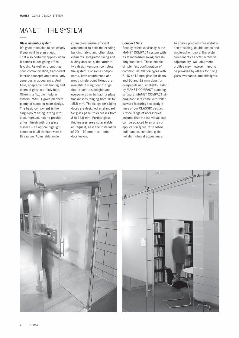
Glass assembly systemIt’s good to be able to see clearly if you want to plan ahead. That also certainly applies when it comes to designing office layouts. As well as promoting open communication, transparent interior concepts are particularly generous in appearance. And here, adaptable partitioning and doors of glass certainly help. Offering a flexible modular system, MANET gives planners plenty of scope in room design. The basic component is the single-point fixing, fitting into a countersunk hole to provide a flush finish with the glass surface – an optical highlight common to all the hardware in this range. Adjustable angle
connectors ensure efficient attachment to both the existing building fabric and other glass elements. Integrated swing and sliding door sets, the latter in two design versions, complete the system. For some compo-nents, both countersunk and proud single-point fixings are available. Swing door fittings that attach to sidelights and overpanels can be had for glass thicknesses ranging from 10 to 15.5 mm. The fixings for sliding doors are designed as standard for glass panel thicknesses from 8 to 17.5 mm. Further glass thicknesses are also available on request, as is the installation of 20 – 40 mm thick timber door leaves.
Compact SetsEqually effective visually is the MANET COMPACT system with its standardized swing and sli-ding door sets. These enable simple, fast configuration of common installation types with 8, 10 or 12 mm glass for doors and 10 and 12 mm glass for overpanels and sidelights, aided by MANET COMPACT planning software. MANET COMPACT sli-ding door sets come with roller carriers featuring the straight lines of our CLASSIC design. A wide range of accessories ensures that the individual sets can be adapted to an array of application types, with MANET pull handles completing the holistic, integral appearance.
To enable problem-free installa-tion of sliding, double-action and single-action doors, the system components all offer extensive adjustability. Wall abutment profiles may, however, need to be provided by others for fixing glass overpanels and sidelights.

MANET CONCEPT MANET COMPACT
Single-point fixing
Connection system
Pivoting door fittings
Sliding door fittings
Pivoting door sets
Sliding door sets
Applications and features
Glass TSG LSG from TSG
TSG LSG from TSG
TSG LSG from TSG
TSG LSG from TSG
TSG TSG
For interior assemblies 3 3 3 3 3 3
Max. door weight (kg) 100 120 80 100
Max. door width (mm) 1200 1500 1200 1200
Max. door height 3000 3000 2500 2500
Masonry openings 3 3 3 3 3
For standard toughened glass assembly types 3 3 3 3 3
For individual designed assemblies 3 3 3
Double action door 3 3
Single action door 3 3
Sliding door 3 3
1-panelled doors 3 3 3 3
2-panelled doors 3 3 3 3Glass thicknesses door (mm) 10 – 15.5 8 – 17.5 10, 12 8, 10, 12
Glass thicknesses overpanel / sidelight 8 – 17.5 8 – 21.5 10 – 15.5 10 – 17.5 10, 12 10, 12
Timber thicknesses sliding door (mm) 20 – 40
Installation and adjustability
Installation at wall 3 3 3 3 3
Installation at ceiling 3 3 3 3
Installation at glass 3 3 3 3 3
Roller at glass 31)
2-D / 3-D adjustable 3 3 3 3 3 3Installation and adjustability
Satin stainless steel 1.4305 3 3 3 3 3 3
Satin stainless steel 1.4404 on request on request on request on request
TREND 3
CLASSIC 3 3
Roller at glass 3Glass preparation
countersunk single-point fixings 3 3 3 3 3 3
clamping disc single-point fixings 3 3 3 3 31)Max. panel weight 80 kg
All elements including the pull handles are supplied in an elegant stainless steel finish. MANET components come in the steel grade 1.4305 (AISI 303) for normal interior applica-tions. Certain selected fittings are also available in 1.4404 (AISI 316L) for damp room and external applications (not suitable saunas or indoor
swimming pools). The materials necessary for your application can be determined from Table 1 of General Building Inspectorate Approval Z-30.3-6 . Note: The products detailed in this brochure are exclusively intended for glass constructions that do not require special indi-vidual inspectorate approval. Awarded with the design prize
red dot 2002
DORMA 5
MANET GLASS DESIGN SYSTEM

MANET CONCEPT —Sliding door system6 – 21
6 DORMA

DORMA 7

8 DORMA
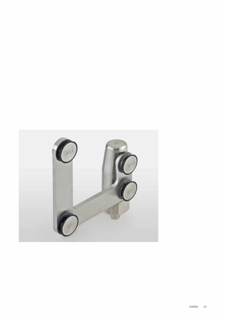
SLIDING DOOR SYSTEM—The MANET sliding door system is ideal as an elegant addition complementing high-style interior concepts. Its main com-ponents take the form of a solid track rail and the roller carrier. Whether you prefer the TREND or CLASSIC versions, both can be combined with the solid track or a tubular track. The range includes both glass-flush and proud single-point fixings. The sliding door system allows plenty of scope for individual ideas.
In addition to the standard ver-sions incorporated in toughened glass partitions or face-fixed on masonry openings, this hard-ware system can also be used to construct curved sliding doors, biparting sliding doors and par-allel sliding doors. The fittings are designed for a door weight of max. 120 kg, resp. 80 kg with roller to glass.Mechanical stops that can be positioned on the track rail ensure that the door travel dis-tance is effectively limited.
Roller carrier TREND Roller carrier CLASSIC
An accordant anti-jump device for solid and tubular tracks will be used.
Roller carrier TREND Roller carrier CLASSIC
Glass connection with drilled solid tracks
Glass connection with clamp fixing and tubular tracks
MANET CONCEPT
DORMA 9
MANET CONCEPT
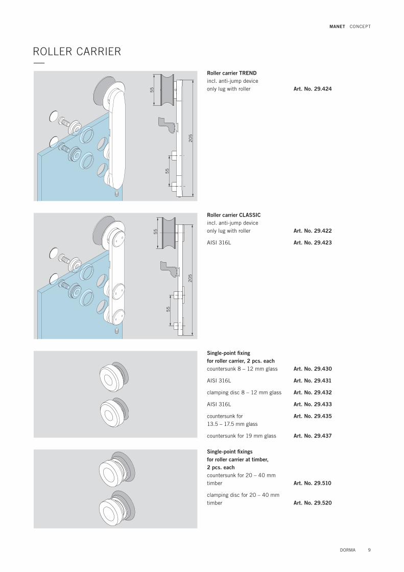
ROLLER CARRIER—
Roller carrier TRENDincl. anti-jump deviceonly lug with roller Art. No. 29.424
20
5
55
55
55
55
20
5
Roller carrier CLASSICincl. anti-jump deviceonly lug with roller
AISI 316L
Art. No. 29.422
Art. No. 29.423
Single-point fixingfor roller carrier, 2 pcs. eachcountersunk 8 – 12 mm glass
AISI 316L
clamping disc 8 – 12 mm glass
AISI 316L
countersunk for 13.5 – 17.5 mm glass
countersunk for 19 mm glass
Art. No. 29.430
Art. No. 29.431
Art. No. 29.432
Art. No. 29.433
Art. No. 29.435
Art. No. 29.437
Single-point fixings for roller carrier at timber, 2 pcs. eachcountersunk for 20 – 40 mm timber
clamping disc for 20 – 40 mm timber
Art. No. 29.510
Art. No. 29.520

10 DORMA
SOLID TRACK—Track supply and installationThe track rail for the sliding door is pre-fabricated according to the customer’s drawing and supplied together with the glass or wall brackets ordered for the application concerned.
Fixing screws for wall installation by othersOf decisive importance for pre-fabrication and fixing to glass partitions is that the mounting points coincide with the holes drilled in the glass. The length-wise tolerances should not be greater than ± 0.3 mm.
For rail support intervals on the glass wall or masonry, see fixing point interval recommendations per the table.
Wall/single-point fixing clearance when using the wallconnector (depends on stopper position).
Caution! Ensure that the stops/single-point fixings are positioned at locations appropriate to the width of the door.
3 100
50
WWGG
100 100
G
K* G GGG
min. 80
min
. 8
0
38
38
3
18
18
G GG G
G = Fixing point at glassW = Fixing point at wall
K = ConnectionWK = Angle-connection
Required dimensions for the track production
Recommended distance of the track fixing points
Door height in mm
Door width in mm700 800 900 1000 1100 1200 1300 1400
Glass thickn. mm Glass thickn. mm Glass thickn. mm Glass thickn. mm Glass thickn. mm Glass thickn. mm Glass thickn. mm Glass thickn. mm8 10 12 8 10 12 8 10 12 8 10 12 8 10 12 8 10 12 8 10 12 8 10 12
1900 770 710 670 770 720 670 770 710 670 760 710 670 760 700 660 750 700 650 740 690 650 730 680 6402000 750 700 650 750 700 660 750 700 650 740 690 650 740 680 640 730 680 640 720 670 630 720 660 6302100 730 680 640 730 680 640 730 680 640 730 670 630 720 670 630 710 660 620 710 660 620 700 650 6102200 710 660 620 710 660 620 710 660 620 710 660 620 700 650 610 700 650 610 690 640 600 680 630 6002300 690 640 610 700 650 610 700 640 610 690 640 600 690 640 600 680 630 600 680 630 590 670 620 5802400 680 630 590 680 630 590 680 630 590 680 630 590 670 620 590 670 620 580 660 610 580 660 610 –2500 660 610 580 670 620 580 670 610 580 660 620 580 660 610 580 650 610 570 650 600 570 640 600 –
see table see table
see table see table see tableWK
max. 5000 with connector max. 5000 with connector
max. 5000 with angle-connector
* Note! Ensure that track joints and glass joints do not coincide
MANET CONCEPT
see table
see table
Track length

DORMA 11
MANET CONCEPT
ø 2
5
Solid track The track rail is prefabricated per customer specifications/ drawing with all the necessary drill holes already provided.
38
38
Threaded rodM5 x 6
Angle connection90 – 180°
* max. single length 5000 mm by coupling
Track, drilledfor fixing at glassfixed length up to 6000 mm
AISI 316L
for fixing at wall up to 6000 mm
AISI 316L
Track, undrilledfor fixing with clamp brackets fixed length up to 6000 mm
do. AISI 316L
Art. No. 21.405
Art. No. 21.456
Art. No. 21.406
Art. No. 21.457
Art. No. 21.407
Art. No. 21.458
Connectorsoffset for tracks 90 – 180°
do. AISI 316L
Art. No. 21.442
Art. No. 21.443
up to 6000 mm*
SOLID TRACK AND ACCESSORIES—
Door stopleft hand
AISI 316L
right hand
AISI 316L
Art. No. 29.425
Art. No. 29.427
Art. No. 29.426
Art. No. 29.428
Wall fixing for tubular track / solid track
AISI 316L
Art. No. 29.445
Art. No. 29.446
56
ø 3
5
20
ø 2
5
left hand
right hand

12 DORMA
MANET CONCEPT
Solid track fixing at ceiling
Flange for fixing the track at wall
AISI 316L
Art. No. 21.346
Art. No. 21.347
Flange for fixing the track at wall, adjustableAdjustment + 5 mmNote: Min. distanceglass to wall 32 mm Art. No. 21.412
Fixing for double track Art. No. 21.170
Ceiling retainer for track
carrying function Art. No. 21.315
10/12
18
60 ø 2
0
35
ø 2
5
ø 5
5
18
ø 2
5
Solid track fixing at wall, adjustable
Solid track fixing at wall
Fixing a double track
ø 65
11
0
ø 25
ø 25
29
2-dimensional adjustmentvia oblong hole
SOLID TRACK AND ACCESSORIES—

DORMA 13
MANET CONCEPT
Selection guide, Solid track fixing for timber doors
Single-point fixing for solid track fixing at glass
28
35
55
371
5
60
X
Z
for X = 20 – 30 mmSingle-point fixing,
countersunk, fixed for 10/12 mm glass
AISI 316L
for 13.5 – 15.5 mm glass
for 17.5 mm glass
clamping disc, fixedfor 10/12 mm glass
AISI 316L
countersunk, centringfor 10/12 mm glass
AISI 316L
for 13.5 – 15.5 mm glass
for 17.5 mm glass
clamping disc, centringfor 10/12 mm glass
AISI 316L
Art. No. 29.460
Art. No. 29.461
Art. No. 29.450
Art. No. 29.451
Art. No. 29.465
Art. No. 29.466
Art. No. 29.462
Art. No. 29.463
Art. No. 29.455
Art. No. 29.456
Art. No. 29.467
Art. No. 29.468
18
ø 2
5
35
ø 2
5
to glass 10/12 mm to wall
X
mm
Z
mm
max.door weight
kg
Single-point fixing fixed for track
Art. No.
Single-point fixing centring for track
Art. No.
Flange for track
Art. No.
countersunk clamping disc
countersunk clamping disc
20 – 30 18.5 120 29.460 29.465 29.462 29.467 21.346
35 – 40 35 100 29.530 – 29.531 – 21.412
for X = 35 – 40 mmSingle-point fixing,
countersunk, fixedfor 10/12 mm glass
countersunk, centringfor 10/12 mm glass
Art. No. 29.530
Art. No. 29.531
Glass thickness
Height adjustment –2,5
Glass thickness
Glass thickness

14 DORMA
3000 mm / 6000 mm
ø 2
5
Tubular trackincl. end plugsstock length 3000 mm
AISI 316L
Fixed length up to 6000 mm
AISI 316L
Art. No. 21.527
Art. No. 21.530
Art. No. 21.436
Art. No. 21.532
Tubular track bent, incl. end plugsmax. curve length 2600 mm
max. curve length 5600 mm
Art. No. 21.409
Art. No. 21.413
40 40
40
ø 2
1ø
21
Angled connection for tubular track, 90° – 180°
Angle connectionfor tubular track
Art. No. 21.535
Art. No. 29.506
Thread insertfor tubular track Art. No. 29.505
Recommended distance of the track fixing points
Door height in mm
Door width in mm700 800 900 1000 1100 1200 1300 1400
Glass thickn. mm Glass thickn. mm Glass thickn. mm Glass thickn. mm Glass thickn. mm Glass thickn. mm Glass thickn. mm Glass thickn. mm8 10 12 8 10 12 8 10 12 8 10 12 8 10 12 8 10 12 8 10 12 8 10 12
1900 350 350 350 400 400 400 450 450 450 500 500 500 550 550 530 600 550 520 590 550 510 580 540 5102000 350 350 350 400 400 400 450 450 450 500 500 500 550 540 510 580 540 510 570 530 500 570 530 5002100 350 350 350 400 400 400 450 450 450 500 500 500 550 530 500 570 530 500 560 520 490 560 520 4902200 350 350 350 400 400 400 450 450 450 500 500 500 550 520 490 550 510 480 550 510 480 540 500 4702300 350 350 350 400 400 400 450 450 450 500 500 500 550 510 480 540 500 470 540 500 470 530 490 4602400 350 350 350 400 400 400 450 450 450 500 500 500 530 500 470 530 490 460 530 490 460 520 480 –2500 350 350 350 400 400 400 450 450 450 500 500 500 520 490 460 520 480 450 520 480 450 510 470 –
TUBULAR TRACKS AND ACCESSORIES—
Curve length
r = m
in. 6
00
mm
MANET CONCEPT
38
38
Threaded rodM5 x 6
Angle connection90 – 180°
see table

DORMA 15
MANET CONCEPT
Clamp fixing for tubular track at glasssingle-point fixing countersunk*
AISI 316L
single-point fixing, clamping disc*
AISI 316L
16 mm extended single-point fixing countersunk*
single-point fixing, clamping disc*
*for 10, 12 and 13.5 mm glass
Art. No. 29.176
Art. No. 29.185
Art. No. 29.177
Art. No. 29.186
Art. No. 29.179
Art. No. 29.180
Clamp fixingfor tubular track at wall
AISI 316L
Art. No. 29.175
Art. No. 29.184
Clamp fixingfor tubular track at wall16 mm extended
AISI 316L
Art. No. 29.178
Art. No. 29.187
18
ø 25
35
ø 25
ø 25
35
18
ø 25
Selection guide, tubular track fixing for timber doors
Tubular track fixing at glass
Tubular track fixing at wall
28
35
55
37X1
5
60
Zto glass to wall
X
mm
Z
mm
max.door weight
kg
Clamp fixing for track Art. No.
Clamp fixing for track Art. No.
countersunk clamping disc
20 – 30 18.5 120 29.175 29.176 29.177
35 – 40 35 100 29.178 29.179 29.180
Glass thickness
Height adjustment –2.5
Glass thickness
Glass thickness

16 DORMA
Ceiling retainerfor tubular track,carrying function Art. No. 21.316
Ceiling retainer doublyfor tubular track,carrying function Art. No. 21.317
ø 65
11
0
ø 25
ø 25
26
ø 65
11
0
ø 25
ø 25
26
Tubular track fixing at ceiling
MANET CONCEPT
56
ø 3
5
20
ø 2
5
Door stopleft hand
AISI 316L
right hand
AISI 316L
Art. No. 29.425
Art. No. 29.427
Art. No. 29.426
Art. No. 29.428
Art. No. 29.445
Art. No. 29.446
left handright hand
TUBULAR TRACK AND ACCESSORIES—
Wall fixing for tubular track / solid track
AISI 316L

DORMA 17
MANET CONCEPT
Anti-jump devicefor roller at glassfor 8 – 12 mm glass,countersunk
clamping disc
Art. No. 29.497
Art. No. 29.498
Roller at glassfor 8 – 12 mm glass,countersunk
clamping disc
Art. No. 29.494
Art. No. 29.495
Door stop for roller at glass, left hand and right hand usable
AISI 316L
Art. No. 29.493
Art. No. 29.483
Roller at glass
70

18 DORMA
Aluminium brush profilesimilar satin stainless steel
for 8 mm glass stock length 3000 mm
fixed length up to 6000 mm
for 10/12 mm glass stock length 3000 mm
fixed length up to 6000 mm
Art. No. 07.402
Art. No. 07.403
Art. No. 07.400
Art. No. 07.401
Sliding door lock with ratchet brace
for 8/10/12 mm glassAISI 316L
Art. No. 21.446
Guide rail with brush sealsapplicable for8/10/12 mm glass
aluminium mill finishedfixed length up to 6000 mm
stock length 3000 mm
Art. No. 21.431
Art. No. 21.432
Floor guideclamping disc,applicable for8/13.5 mm glassArt. No. 07.316 aluminium 113 (similar satin stainless steel)
Art. No. 07.316
55
14
75
38
ø 4
8
ø 3
815.5 for 8 mm glass13.5 for 10 mm glass11.5 for 12 mm glass
ACCESSORIES—
30
102
4
24
30
15
15
MANET CONCEPT

DORMA 19
MANET CONCEPT
ø 16
94
32
ø 25
3
ø 40
28
12
21
ø 5
5
ø 5
5
6565
11
3
77
65
73
Corner lock for 8 – 12 mm glass,
Corner lock with profile cylinder rose on inside for 8 – 12 mm glass
Dead lock for KABA with rose on inside for 8 – 12 mm glass
Profile cylinder for corner lock
Art. No. 21.448
Art. No. 21.449
Art. No. 21.450
Art. No. 14.206
Eccentric bushingfor corner lock
Bushing, plastics
Strike plate Art. No. 05.190
Art. No. 05.194
Art. No. 00.110
Glass thickness
Floor Floor
Floor
Door steady, to prevent glass edges of bi-parting double sliding doors
Please order for details for glass preparations our detail sheet 29-044-B.
Art. No. 29.420
50
356
MANET CONCEPT

20 DORMA
MANET CONCEPT
Sliding door with two sidelights and overpanel
Sliding door with sidelight and overpanel
Sliding door to wall
Detail A Detail B
Wall Sliding door Wall
GLASS PREPARATION FOR SLIDING DOOR SYSTEM—
Wall
Sidelight
Sliding door
Sliding door
Overpanel
Overpanel
Sidelight
Sidelight
Detail C
Detail E
Detail D
Detail D

DORMA 21
40
143
40
143
55
50 2
8
28
60
35
18
55
50 2
8
28
60
35
18
Sliding door with tubular track and clamp fixing
Sliding door with solid track
143 143143
40
5050
3
Detail E
50 100
3
40
143
Detail A
Detail C
Detail B
Detail D
ø 2
6
ø 2
2
ø 3
2+0
,2
–0,2
90
°
3
Countersunk bore for countersunk single-point fixings
Cylindrical bore for clamping disc single-point fixings
Dimensional data should be regarded exclusively as recom-mended values. Please remember when designing your system that the positions of the stops and point fixings must not vertically coincide. For spacing/interval recommen-dations when drilling the track holes, and for requisite dimen-sions for fixing the track rail,please refer to the table entitled “Recommended distance of the track fixing points”.
Glass thickness
Glass thickness
MANET CONCEPT
glass edge protectionon site

MANET CONCEPT —Pivoting door system22 – 35
22 DORMA
DORMA 23

PIVOTING DOOR SYSTEM—MANET pivoting doors can be installed in both glass partitions and masonry openings. They come as both single and double-action swing doors with a maximum weight of 100 kg and a maximum leaf width of 1200 mm.All the single-point fixings are designed for clip-on covers for easier installation. Other com-ponents include the bottom pivot bearing, top pivot fittings with bearing spigot or eccentric bushing and also overpanel/sidelight connectors.As a result, there are almost unlimited possibilities for inte-grating frameless swing doors
both in masonry openings – with or without overpanels and side-lights – and in glass partition constructions retained by single-point fixings.Whether with a full-length pivot rod or a pair of shorter pivot rods, the top bearing socket is located in the fitting on the door leaf. This means that connection to the ceiling, lintel or transom can now be provided in the form of the standard PT25 top pivot spigot from the DORMA range.The door assemblies can be equipped with floor springs such as the DORMA BTS 75V or BTS 84, and corner locks are naturally also available.
Pivot bearing with full-length pivot rod, max. door panel height 3000 mm
Pivot bearing with pivot rod pair short type, max. door panel height 2500 mm
Pivot bearing withpivot rod pair short type with intermediate tube, max. door panel height 2500 mm
Adjustment+ 2.5
Bottom pivot bearing
Pivot pole Adjustment+ 2.5
Zero position
24 DORMA
MANET CONCEPT

COMPONENTS FOR PIVOTING DOOR SYSTEM—
18
76
Overpanel / sidelight connectorcomplete fittingfor 10/12 mm glasscountersunk
AISI 316L
clamping disc
Art. No. 29.330
Art. No. 29.362
Art. No. 29.356
Pivot bearing for overpanel and ceiling connection
AISI 316L
Art. No. 21.310
Art. No. 21.350
Pivot bearing for DORMA BTS (max. 4 EN) / floor pivot
AISI 316L
Art. No. 29.545
Art. No. 29.550
18
76
11
5
18
Glass thickness
DORMA 25
MANET CONCEPT

Pivot rod,drilled, fixed length
Single-point fixing, countersunk, fixed (1)
for 10/12 mm glass
AISI 316L
for 13.5 – 15.5 mm glass
clamping disc, fixed (1)
for 10/12 mm glass
AISI 316L
Single-point fixing, countersunk, centring (2)
for 10/12 mm glass
AISI 316L
for 13.5 – 15.5 mm glass
clamping disc, centring (2)
for 10/12 mm glass
Art. No. 29.551
Art. No. 29.460
Art. No. 29.461
Art. No. 29.450
Art. No. 29.465
Art. No. 29.466
Art. No. 29.462
Art. No. 29.463
Art. No. 29.455
Art. No. 29.467
Pivot rod set, short type top/bottom,incl. 4 single-point fixingscountersunk
AISI 316L
clamping disc
AISI 316L
Art. No. 29.546
Art. No. 29.547
Art. No. 29.560
Art. No. 29.561
18
83
ø 3
2
ø 25
89
ø 3
2
1
2
2
2
COMPONENTS FOR PIVOTING DOOR SYSTEM—
Glass thickness
26 DORMA
MANET CONCEPT

Floor pivot Art. No. 01.106
Pivot bearing for humid rooms AISI 316L
Art. No. 29.540
15
92
32
18
76
inte
rmed
iate
tub
e
Intermediate tubefixed length up to 2000 mm
AISI 316L
Art. No. 29.555
Art. No. 29.557
Pivot rod set, short type top / bottom, for intermediate tube, inclusive 4 single-point fixings
countersunk
AISI 316L
clamping disc
AISI 316L
Art. No. 29.548
Art. No. 29.549
Art. No. 29.562
Art. No. 29.563
DORMA 27
MANET CONCEPT

Overpanel / sidelight connector for wall fixing90° offset, complete fittingfor 10/12 mm glass
70 70 33
74
74
12
0
12
0
Wall fixingOverpanel / sidelight connector for wall fixing90° offset, with pivot bearing location,complete fittingfor 10/12 mm glass
right hand Art. No. 29.328
right hand Art. No. 29.326
left hand Art. No. 29.329
left hand Art. No. 29.327
7070
74
74
3 3
18
12
0
18
12
0
COMPONENTS FOR PIVOTING DOOR SYSTEM—
28 DORMA
MANET CONCEPT

Overpanel / sidelight connector for glass fixing90° offset, with pivot bearing location,complete fittingfor 10/12 mm glass
Overpanel / sidelight connector for glass fixing90° offset, with pivot bearing location,complete fittingfor 10/12 mm glass
left hand Art. No. 29.332
right hand Art. No. 29.331
Glass fixing
70 3
73
7037
31
20
18
11
51
20
18
11
5
Glass thickness
Glass thickness
12
04
03
Overpanel / sidelight connection for 10/12 mm glass,countersunk
clamping disc
Art. No. 29.320
Art. No. 29.357
Glass thickness
DORMA 29
MANET CONCEPT

ø 25
18
60
11
5
PT 25 pin for ceiling connection,15 mm Ø, with plug Art. No. 01.115
Pivot bearing for RTS
Pivot pole, drilled, fixed length, for RTS pivot bearing 29.314
Art. No. 29.314
Art. No. 29.553
Pivot bearing for installation to ceilingadjustablefor 8 – 12 mm glass,AISI 316L
Art. No. 21.319
Art. No. 21.318
Pivot bearing fittingfor overpanel with cylindrical bore for rodfor 8 – 12 mm glass,countersunk Art. No. 29.354
105
46
76
3
18
76
Glass thickness
Glass thickness
M8
40
11
5
18
Pivot bearing locationfor overpanelfor 8 – 12 mm glass,countersunk
AISI 316L
Art. No. 29.333
Art. No. 29.353
Glass thickness
COMPONENTS FOR PIVOTING DOOR SYSTEM—
30 DORMA
MANET CONCEPT

Stop for pivoting doorwith ceiling mounting Art. No. 21.334
Stop at overpanel(inside/outside)for 10/12 mm glass, Art. No. 29.335
Overpanel / sidelight connectionwith stop insidefor 10/12 mm glass,countersunk Art. No. 29.322
Overpanel / sidelight connectionwith stop outside for 10/12 mm glass, countersunk Art. No. 29.325
ACCESSORIES—
530
39
40
34
01
20
73
40
30
40
12
0
3
Ceiling
Glass thickness
Glass thickness
Glass thickness
DORMA 31
MANET CONCEPT

Stop for pivoting doorfloor mounting Art. No. 29.950
Stop for pivoting doorwall mounting, short Art. No. 29.951
Stop for pivoting doorwall mounting, long Art. No. 29.952
40
24
ø 2
0 31
94
ø 2
0
GlassWall
Floor
Glass Wall
Glass Wall
ACCESSORIES—
32 DORMA
MANET CONCEPT

ø 16
94
32
ø 25
3
ø 40
28
12
21
ø 5
5
ø 5
5
6565
11
3
77
65
73
Corner lock for 8 – 12 mm glass,
Corner lock with profile cylinder rose on inside for 8 – 12 mm glass
Dead lock for KABA with rose on inside for 8 – 12 mm glass
Profile cylinder for corner lock
Art. No. 21.448
Art. No. 21.449
Art. No. 21.450
Art. No. 14.206
Eccentric bushingfor corner lock
Bushing, plastics
Strike plate Art. No. 05.190
Art. No. 05.194
Art. No. 00.110
Glass thickness
Floor Floor
Floor
DORMA 33
MANET CONCEPT
Detail A
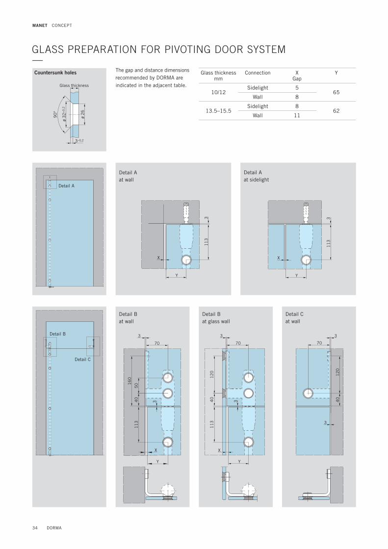
The gap and distance dimensions recommended by DORMA are indicated in the adjacent table.
GLASS PREPARATION FOR PIVOTING DOOR SYSTEM—
ø 2
6
ø 3
2+0
,2
90
°
3–0,2
Countersunk holes Glass thickness mm
Connection X Gap
Y
10/12Sidelight 5
65Wall 8
13.5–15.5Sidelight 8
62Wall 11
Detail B
Detail C
Detail A at wall
Detail B at wall
Detail B at glass wall
Detail C at wall
Detail A at sidelight
X
Y
11
33
X
Y
11
33
X
Y
11
3
16
0
40
50
3
70
3
X
Y
11
34
01
20
3
70
3 40
12
0
3
3
70
Glass thickness
34 DORMA
MANET CONCEPT

18
24
7
11
3
11
34
05
0
3X1
± 0
,3
X1 ±
0,3
X3 ±
0,3
89
12
0
Y
X
Y
3
50 67
3
67 50
3
3 40
12
0
3
3
67 50
3 40
12
0
Detail D
Detail D
Detail E
Detail E with stop
Detail EDetail B
Detail E
Glass BTS
DORMA 35
MANET CONCEPT

36 DORMA
MANET CONCEPT —Connection system36 – 43

DORMA 37

38 DORMA
MANET CONCEPT
CONNECTION SYSTEM—The system approach is very much in evidence in the case of the interconnecting components. Elements such as clamping and angle connectors of various designs and also interconnecting
fasteners of various lengths can be combined in order to attach glass of different thicknesses at any required angle to the floor, to ceilings, to walls and to plinth supports.
Single-point fixings flush with the glass are also used for this interconnection and glass-to-glass system. Tolerances are compensated by sloted holes in the interconnecting fasteners.
90° – 180° Glass / WallGlass / Glass Connector90° – 180° Glass / Glass
Glass fixing
1 2 3 45
6
8
Wall fixing
Components
1 Clip-on cover 2 Connecting bolt 3 Conical collar 4 Conical sleeve 5 Gasket 6 Pivoting clamp 7 Connecting bolt 8 Connecting rod to suit
length
Components
9 Connecting bolt10 Pivoting clamp11 Threaded rod M8 with small
head, Length and type to suit wallplug
12 Mounting plate, 2-dimensional adjustment
13 Wallplug on site to suit wall construction
7
8
9
1011 12
13

DORMA 39
MANET CONCEPT
CLAMP CONNECTION GLASS—
CONNECTION CEILING / FLOOR—
ALTERNATIVE CONNECTION CEILING—
23
45
56
Ceiling suspension only permissible with bottom glass panel support.
Single-point fixing clamping disc
Single-point fixing countersunk
12
Components
1 Connecting rod or steel cable
2 Connecting bolt3 Pivoting clamp4 Connecting bolt5 Gasket 6 Pivoting clamp
Components
7 Wallplug on site8 Mounting plate,
2-dimensional adjustable9 Threaded rod M810 Column
Components
11 Threaded rod M8 DIN 7984 M10 x..., or oval-head wood screw DIN 7996 M8 x...
12 Clip-on cover
1
7
8
9
10
11
40 DORMA
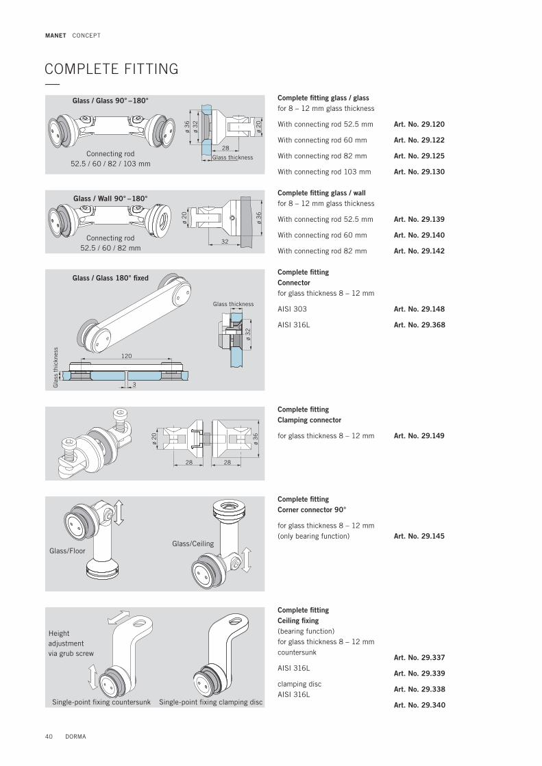
Complete fitting Ceiling fixing(bearing function)for glass thickness 8 – 12 mm countersunk
AISI 316L
clamping discAISI 316L
Art. No. 29.337
Art. No. 29.339
Art. No. 29.338
Art. No. 29.340
120
3
ø 3
2
Height adjustmentvia grub screw
Single-point fixing clamping discSingle-point fixing countersunk
32
ø 2
0
ø 3
6
COMPLETE FITTING—
Complete fittingConnectorfor glass thickness 8 – 12 mm
AISI 303
AISI 316L
Art. No. 29.148
Art. No. 29.368
Complete fitting Clamping connector
for glass thickness 8 – 12 mm Art. No. 29.149
Complete fitting Corner connector 90°
for glass thickness 8 – 12 mm (only bearing function) Art. No. 29.145
Complete fitting glass / glassfor 8 – 12 mm glass thickness
With connecting rod 52.5 mm
With connecting rod 60 mm
With connecting rod 82 mm
With connecting rod 103 mm
Art. No. 29.120
Art. No. 29.122
Art. No. 29.125
Art. No. 29.130
Complete fitting glass / wallfor 8 – 12 mm glass thickness
With connecting rod 52.5 mm
With connecting rod 60 mm
With connecting rod 82 mm
Art. No. 29.139
Art. No. 29.140
Art. No. 29.142
Connecting rod52.5 / 60 / 82 / 103 mm
Connecting rod52.5 / 60 / 82 mm
Glass / Glass 90° – 180°
Glass / Wall 90° – 180°
28 28
ø 2
0
ø 3
6
28
ø 2
0
ø 3
2ø
36
Glass/FloorGlass/Ceiling
Glass thickness
Glass thickness
Gla
ss t
hick
ness
MANET CONCEPT
Glass / Glass 180° fixed

DORMA 41
COMPONENTS—
52 mm
82 mm
60 mm
103 mm
Pivoting glass clampinclusive screw sets for 8 – 12, 13.5 – 17.5 and 17.5 – 21.5 mm glass, countersunk
do., clamping disc
Art. No. 29.160
Art. No. 29.165
ColumnCeiling/floor fixing Art. No. 21.146
Clamping connectorfor Glass thickness 8 – 12 mm Art. No. 29.149
Pivoting wall fixing Art. No. 21.141
Connecting rods
Length 52.5 mm
Length 60 mm
Length 82 mm
Length 103 mm
Art. No. 21.355
Art. No. 21.356
Art. No. 21.357
Art. No. 21.358
MANET CONCEPT

42 DORMA
For TSG and LSG from TSG.
3
28
3
90° 28
Corner connectors glass / glass 90 – 180°
GLASS PREPARATION CONNECTION SYSTEM—
90°
ø 26
ø 32 + 0,2
3 –
0,2
Countersunk bore for countersunk single-point fixingsRecommended centres for fixed glazing element
Cylindrical bore for clamping disc single-point fixings
Corner connectors glass / glass (dimensions in mm)
Length of connecting rod
52,5 60 82 103
Dimensions for 10 mm glass thickness (consider variants
for other glass thicknesses).
Angle A/B A/B A/B A/B
90° 75 80 96
95° 70 75 90
100° 66 71 85
105° 62 67 81
110° 59 63 77
115° 55 60 73
120° 52 56 69
125° 49 54 66
130° 47 51 63
135° 44 48 60
180° 50
ø 26 + 0,2
max. 800 ± 0.3
max
. 8
00
± 0
.3
± 0
.3
Gla
ss t
hick
ness
Gla
ss t
hick
ness
Dim
ensi
on A
Dimension A
Dimension B Dimension B
Connecting rod
Connecting rod
Angle
MANET CONCEPT
0.2
.
0.2

DORMA 43
Clamping connector
150
28
28 3
60
ø 1
5
67
Corner connector glass / ceiling Corner connector glass / floor Ceiling fixing (bearing)
Glass / wall (dimensions in mm)
Note: Ensure compliance with minimum glass/bore clearances as per glass manufacturer recommendations.Glass preparation with a tolerance of max. ± 0.3 mm is recommended.
72 75
28
37
2
75
28
65
5
42
Length of connecting rod
52,5 60 82
Dimensions for 10 mm glass thickness (consider variants for
other glass thicknesses).
Angle A/B A/B A/B
90° 67/65 72/70 87,5/86
32
3
28
Corner connectors glass / wall 90 – 180°
Dimension B
Dim
ensi
on A
Connecting rod
Angle
Wall
Ceiling
FloorGlass thickness
Vertically adjustment ± 2.5
Ceiling
KS
MANET CONCEPT
44 DORMA
MANET CONCEPT —Single-point fixing44 – 49

DORMA 45
46 DORMA
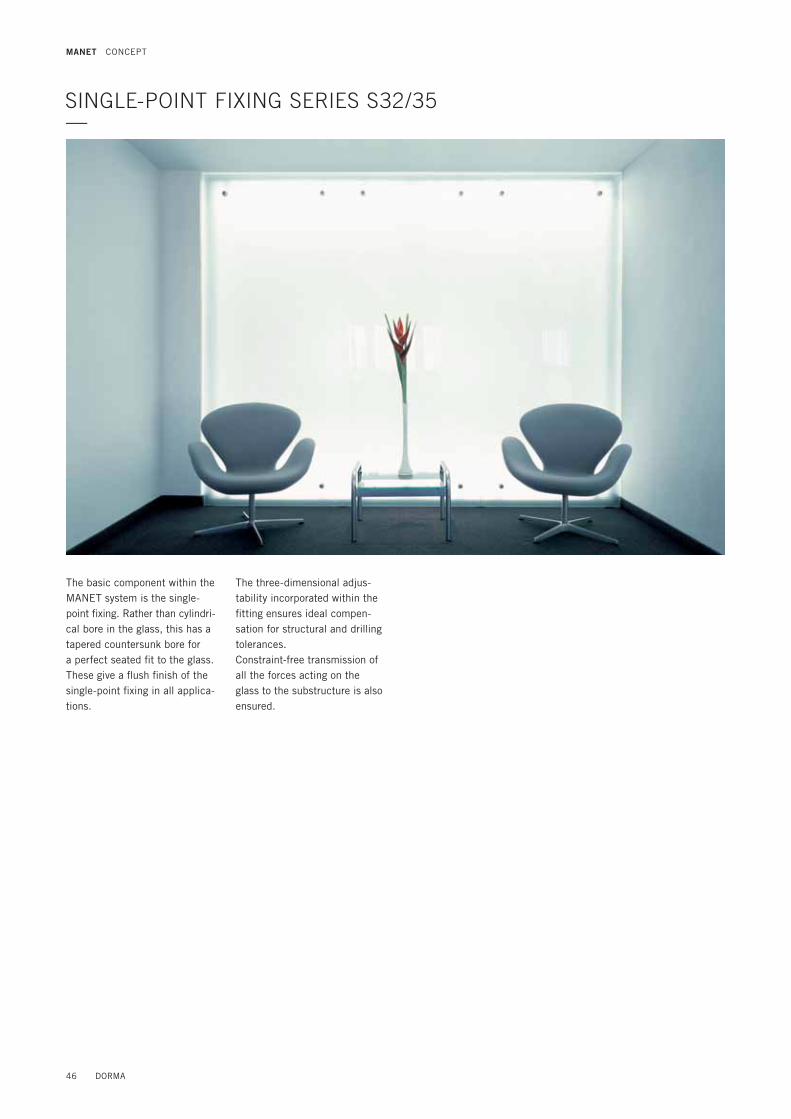
SINGLE-POINT FIXING SERIES S32/35—
The basic component within the MANET system is the single-point fixing. Rather than cylindri-cal bore in the glass, this has a tapered countersunk bore for a perfect seated fit to the glass. These give a flush finish of the single-point fixing in all applica-tions.
The three-dimensional adjus-tability incorporated within the fitting ensures ideal compen-sation for structural and drilling tolerances.Constraint-free transmission of all the forces acting on the glass to the substructure is also ensured.
MANET CONCEPT

DORMA 47
Simple installation and metric adjustmentThe fixing and the gasket are wound onto the adjustment screw already fitted to the wall, with the glass panel then being simply mounted over the top. The adjustment screw allows the position of the glass to be adjusted in 3 dimensions.
An adjustment range of ±2 mm in the vertical and lateral direc-tions can be utilized by rotating the adjustment screw by up to 90°. Then it is simply a matter of aligning and securing the single-point fixing and conical sleeve. The clip-on cover provides for a flush appearance.
Components
1 Clip-on cover2 Pin internal thread3 Conical sleeve4 Gasket5 Fixing6 Threaded rod M8 with
small head (eg DIN 6912). Length and type to suit wallplug
7 Adjustment screw8 Wallplug on site to suit wall
construction
1
23
4
5
6 7
8
MANET CONCEPT
48 DORMA
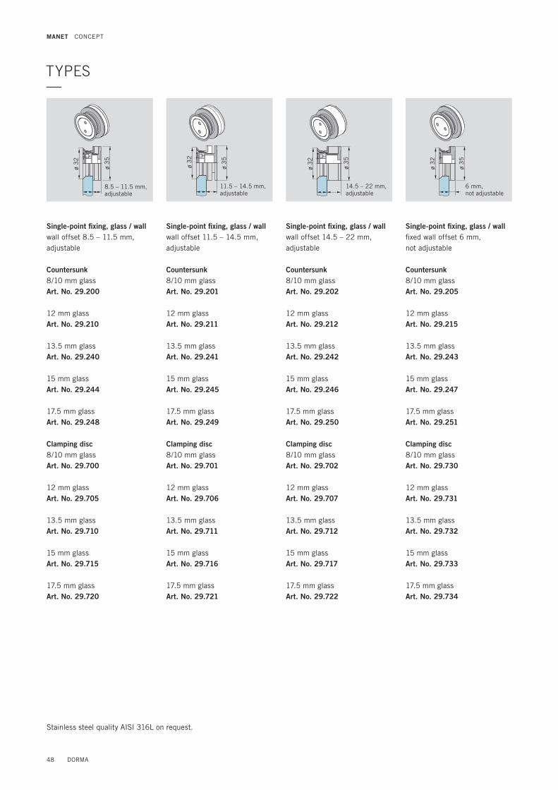
TYPES—
Single-point fixing, glass / wallwall offset 8.5 – 11.5 mm, adjustable
Countersunk8/10 mm glass Art. No. 29.200 12 mm glass Art. No. 29.210
13.5 mm glassArt. No. 29.240
15 mm glassArt. No. 29.244
17.5 mm glassArt. No. 29.248
Clamping disc8/10 mm glass Art. No. 29.700 12 mm glassArt. No. 29.705
13.5 mm glassArt. No. 29.710
15 mm glassArt. No. 29.715
17.5 mm glassArt. No. 29.720
Single-point fixing, glass / wallwall offset 11.5 – 14.5 mm, adjustable
Countersunk8/10 mm glass Art. No. 29.201 12 mm glass Art. No. 29.211
13.5 mm glassArt. No. 29.241
15 mm glassArt. No. 29.245
17.5 mm glassArt. No. 29.249
Clamping disc8/10 mm glass Art. No. 29.701 12 mm glassArt. No. 29.706
13.5 mm glassArt. No. 29.711
15 mm glassArt. No. 29.716
17.5 mm glassArt. No. 29.721
Single-point fixing, glass / wallwall offset 14.5 – 22 mm, adjustable
Countersunk8/10 mm glass Art. No. 29.202 12 mm glass Art. No. 29.212
13.5 mm glassArt. No. 29.242
15 mm glassArt. No. 29.246
17.5 mm glassArt. No. 29.250
Clamping disc8/10 mm glass Art. No. 29.702 12 mm glassArt. No. 29.707
13.5 mm glassArt. No. 29.712
15 mm glassArt. No. 29.717
17.5 mm glassArt. No. 29.722
Single-point fixing, glass / wallfixed wall offset 6 mm, not adjustable
Countersunk8/10 mm glass Art. No. 29.205 12 mm glass Art. No. 29.215
13.5 mm glassArt. No. 29.243
15 mm glassArt. No. 29.247
17.5 mm glassArt. No. 29.251
Clamping disc8/10 mm glass Art. No. 29.730 12 mm glassArt. No. 29.731
13.5 mm glassArt. No. 29.732
15 mm glassArt. No. 29.733
17.5 mm glassArt. No. 29.734
ø 3
2
ø 3
5
ø 3
2
ø 3
5
ø 3
2
ø 3
5
ø 3
2
ø 3
5
Stainless steel quality AISI 316L on request.
8.5 – 11.5 mm, adjustable
11.5 – 14.5 mm, adjustable
14.5 – 22 mm, adjustable
6 mm, not adjustable
MANET CONCEPT

DORMA 49
90°
ø 26
ø 32 + 0,2
3 –
0,2
ø 26 + 0,2
Countersunk bore for countersunk single-point fixings Cylindrical bore for clamping disc single-point fixings
max. 800 ± 0.3
max
. 8
00
± 0
.3
± 0
.3
Gla
ss
thic
knes
s
MANET CONCEPT
For TSG and LSG from TSG.
GLASS PREPARATION CONNECTION SYSTEM—
Recommended centres for fixed glazing element
Gla
ss
thic
knes
s

MANET COMPACT SETS —Pivoting doors53 – 55
Sliding doors56 – 61
50 DORMA

DORMA 51

MANET COMPACT SETS —
Pivoting doorsSet 1Page 53
Pivoting doors with overpanelSet 2Page 54
Pivoting doors with overpanel and sidelightSet 3Page 55
Sliding doorsSet 4/5/6Page 56 – 61
Construction 1 (1 set)
Construction 5 (2 sets)
Construction 9 (1 set)
Construction 13 (1 set)
Set 4.1/4.2
Construction 2 (1 set)
Construction 6 (2 sets)
Construction 12 (1 set)
Construction 15 (1 set)
Set 5.1/5.2
Construction 3 (1 set)
Construction 7 (2 sets)
Construction 18 (2 sets)
Construction 23 (2 sets)
Set 6.1/6.2
Construction 4 (1 set)
Construction 8 (2 sets)
The aesthetic elegance of the MANET COMPACT concept is also available in the form of standardised sets for simple, fast planning of the more popu-lar system types.Optional accessories enable the individual sets to be semi-custo-mised.The system components offer numerous adjustment possibili-
ties in order to ensure problem-free installation of whichever door type – sliding or swing, single action or double action – is required.Wall abutment profiles may need to be provided (by others) for fixing overpanels and side-lights. (See technical brochure ”Fittings and door rails for toughened glass assemblies”.)
Construction (1 Set each)
Pivoting doorsSet 2 + 3Page 54/55
52 DORMA
MANET COMPACT SETS

Set 1 with single-point fixings countersunk consisting of: pivot rod pair top/bottom, short type Art. No. 29.910
including:4 Single-point fixings for pivot rods1 Pivot fitting top,1 PT 25 pin, 15 mm Ø, with plug1 Pivot fitting bottom
for DORMA BTS/floor pivot
Option: Set 1, but for additional intermediate tube in fixed length for pivot rod pair Art. No. 29.911Intermediate tube in fixed length Art. No. 29.555
Please indicate: Panel height ____________________________________________ mm – 577 mm = Length intermediate tube ____________________________________________ mm
65
65
15
01
50
11
31
13
Pivoting door MANET COMPACT without overpanel for 10 – 12 mm glassSet 1with pivot rod pair short type
For the requisite glass preparation please see pages 34 – 35
SET 1—
Accessory options for Set 1
Pull handles
Pull handles Length 350 mm Art. No. 29.268
(single-point fixing countersunk) Length 720 mm Art. No. 29.271
Length 1240 mm Art. No. 29.274
Length 1760 mm Art. No. 29.277
Pair of pull handles Length 350 mm Art. No. 21.267
Length 720 mm Art. No. 21.270
Length 1240 mm Art. No. 21.273
Length 1760 mm Art. No. 21.276
Lock
Corner lock Art. No. 21.448
Corner lock with rose on one lock side Art. No. 21.449
Profile cylinder for corner lock 21.448/449 Art. No. 14.206
Eccentric bushing for corner lock 21.448/449 Art. No. 05.194
Further accessories
Stop for pivoting door with ceiling mounting Art. No. 21.334
Ceiling fixing (bearing function) Art. No. 29.337
Floor pivot bearing Art. No. 01.106
Assembling tool for MANET single-point fixings Art. No. 21.134
Door weight 80 kg Door height max. 2500 mm Door width max. 1200 mm TSG 10/12 mm glass thickness
DORMA 53
MANET COMPACT SETS
Ceiling
3 G
ap
Gapto sidelight 5to wall 8
7 G
ap
DORMA BTS

65
65
15
01
50
11
31
13
Set 2 with single-point fixings countersunk consisting of: pivot rod pair top/bottom, short type Art. No. 29.912
including:4 Single-point fixings for pivot rods,1 Pivot fitting top,1 Pivot bearing location for overpanel,1 Pivot fitting bottom
for DORMA BTS/floor pivot
Option: Set 2, but with additional intermediate tube in fixed length for pivot rod pair Art. No. 29.913Intermediate tube in fixed length Art. No. 29.555
Please indicate: Panel height ____________________________________________ mm – 577 mm = Length intermediate tube ____________________________________________ mm
Pivoting door MANET COMPACT with overpanel for 10 – 12 mm glassSet 2with pivot rod pair short type
For the requisite glass preparation please see pages 34 – 35
SET 2—
Accessory options for Set 2
Pull handles
Pull handles Length 350 mm Art. No. 29.268
(single-point fixing countersunk) Length 720 mm Art. No. 29.271
Length 1240 mm Art. No. 29.274
Length 1760 mm Art. No. 29.277
Pair of pull handles Length 350 mm Art. No. 21.267
Length 720 mm Art. No. 21.270
Length 1240 mm Art. No. 21.273
Length 1760 mm Art. No. 21.276
Ceiling fixing (bearing function) Art. No. 29.337
Stop at overpanel, (inside/outside) for 10 and 12 mm glass Art. No. 29.335
Lock
Corner lock Art. No. 21.448
Corner lock with rose on one lock side Art. No. 21.449
Profile cylinder for corner lock 21.448/449 Art. No. 14.206
Eccentric bushing for corner lock 21.448/449 Art. No. 05.194
Further accessories
Overpanel-sidelight connector for 10 and 12 mm glass Art. No. 29.320
Overpanel-sidelight connector with stop inside for 10 and 12 mm glass Art. No. 29.322
Overpanel-sidelight connector with stop outside for 10 and 12 mm glass Art. No. 29.325
Floor pivot bearing Art. No. 01.106
Assembling tool for MANET single-point fixings Art. No. 21.134
Door weight 80 kg Door height max. 2500 mm Door width max. 1200 mm TSG 10/12 mm glass thickness
54 DORMA
MANET COMPACT SETS
Overpanel
3 G
ap
Gap to wall 8
7 G
ap
DORMA BTS
Wal
l
65
65
15
01
50
11
31
13
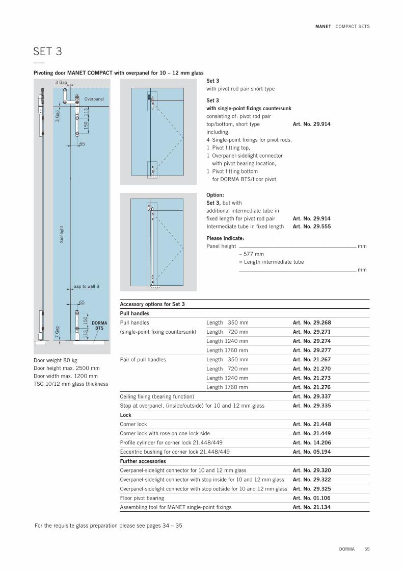
Set 3 with single-point fixings countersunk consisting of: pivot rod pair top/bottom, short type Art. No. 29.914including:4 Single-point fixings for pivot rods,1 Pivot fitting top,1 Overpanel-sidelight connector
with pivot bearing location,1 Pivot fitting bottom
for DORMA BTS/floor pivot
Pivoting door MANET COMPACT with overpanel for 10 – 12 mm glassSet 3with pivot rod pair short type
For the requisite glass preparation please see pages 34 – 35
SET 3—
Accessory options for Set 3
Pull handles
Pull handles Length 350 mm Art. No. 29.268
(single-point fixing countersunk) Length 720 mm Art. No. 29.271
Length 1240 mm Art. No. 29.274
Length 1760 mm Art. No. 29.277
Pair of pull handles Length 350 mm Art. No. 21.267
Length 720 mm Art. No. 21.270
Length 1240 mm Art. No. 21.273
Length 1760 mm Art. No. 21.276
Ceiling fixing (bearing function) Art. No. 29.337
Stop at overpanel, (inside/outside) for 10 and 12 mm glass Art. No. 29.335
Lock
Corner lock Art. No. 21.448
Corner lock with rose on one lock side Art. No. 21.449
Profile cylinder for corner lock 21.448/449 Art. No. 14.206
Eccentric bushing for corner lock 21.448/449 Art. No. 05.194
Further accessories
Overpanel-sidelight connector for 10 and 12 mm glass Art. No. 29.320
Overpanel-sidelight connector with stop inside for 10 and 12 mm glass Art. No. 29.322
Overpanel-sidelight connector with stop outside for 10 and 12 mm glass Art. No. 29.325
Floor pivot bearing Art. No. 01.106
Assembling tool for MANET single-point fixings Art. No. 21.134
Door weight 80 kg Door height max. 2500 mm Door width max. 1200 mm TSG 10/12 mm glass thickness
Option: Set 3, but with additional intermediate tube in fixed length for pivot rod pair Art. No. 29.914Intermediate tube in fixed length Art. No. 29.555
Please indicate: Panel height ____________________________________________ mm – 577 mm = Length intermediate tube ____________________________________________ mm
DORMA 55
MANET COMPACT SETS
Overpanel
3 G
ap
Gap to wall 8
7 G
ap
DORMA BTS
Sid
elig
ht
3 Gap

SET 4.1/4.2—
143
60
40 40
143143
85
X X X X
Sliding door MANET COMPACT for installation at wall, for 8 – 12 mm glass
For the requisite glass preparation please see pages 20 – 21
Set 4.1 with single-point fixings countersunk
Set 4.2 with clamping disc single-point fixings
LM = Daylight opening TB = Door width DGB = Entry width LL = Tubular track lengthX = Distance of single-point
fixings (LM – 148) * 1/2
Door weight 80 kg Door height max. 2500 mm Door width max. 1200 mm TSG 10/12 mm glass thickness
56 DORMA
MANET COMPACT SETS
Doo
r he
ight
max
. 25
00
mm
Fixed length: LL = 2 * TB – 170 mm
DBG = LM – 130 mm
LM
TB = LM + 80 mm

Sliding door MANET COMPACT for installation at wall, for 8 – 12 mm glass
Set 4.1 / Set 4.2 Set 4.1 Set 4.2consisting of: with single-point fixings with clamping disc single-point countersunk fixings
5 Clamp fixings for track / wall Art. No. 29.916 Art. No. 29.9172 Roller carriers CLASSIC
incl. single-point fixings for 8 – 12 mm glass1 Door stop left hand1 Door stop right hand1 Floor guide AGILEInstallation tools
Set as above, but with 16 mm extended clamp fixing Art. No. 29.925 Art. No. 29.926
Not covered by the set:Tubular track inclusive end cups in fixed length* Art. No. 21.436 Art. No. 21.436
Tubular track, inclusive end cups, stock length 3000 mm Art. No. 21.527 Art. No. 21.527
* When ordering please indicate the necessary length! For calculation please see adjoining page
Accessory options for Set 4.1 / Set 4.2
Pull handles / Recessed pull grip
Pull handles Length 350 mm Art. No. 29.268 Art. No. 21.240
Length 720 mm Art. No. 29.271 Art. No. 21.241
Length 1240 mm Art. No. 29.274 Art. No. 21.242
Length 1760 mm Art. No. 29.277 Art. No. 21.243
Pair of pull handles Length 350 mm Art. No. 21.267
Length 720 mm Art. No. 21.270
Length 1240 mm Art. No. 21.273
Length 1760 mm Art. No. 21.276
Recessed pull grip Ø 60 mm for 8/10/12 mm glass Art. No. 21.291
Recessed pull grip with grip hole Ø 60 mm for 8 mm glass Art. No. 21.292
for 10 mm glass Art. No. 21.293
for 12 mm glass Art. No. 21.294
Door knob back-to-back for 8 – 12 mm glass Art. No. 21.423
Door knob one side fixing for 8 – 12 mm glass Art. No. 21.422 Art. No. 21.426
Corner lock
Corner lock Art. No. 21.448
Corner lock with rose on one lock side Art. No. 29.449
Profile cylinder for corner lock 21.448/449 Art. No. 14.206
Eccentric bushing for corner lock 21.448/449 Art. No. 05.194
Further accessories
Aluminium guide rail with brush seals
stock length 3000 mm Art. No. 21.432
stock length 6000 mm Art. No. 21.430
Assembling tool for MANET single-point fixing Art. No. 21.134
DORMA 57
MANET COMPACT SETS

SET 5.1/5.2—
40
60
20
40
143
70
143 143
50
50
X X Y Y
Sliding door MANET COMPACT for installation at glass, one side attached to masonry,
For the requisite glass preparation please see pages 20 – 21
for sliding door 8 – 12 mm glass,fixed element 10 – 12 mm glass
Set 5.1 with countersunk single-point fixings
Set 5.2 with clamping disc single-point fixing
LM = Daylight openingTB = Door widthDGB = Entry widthSBmin. = min. SeitenteilbreiteLL = Tubular track lengthX = Centre distance
between single-point fixings overpanel (OB – 193) * 1/2
Y = Centre distance between single-point fixings sidelight Y = X – 29
OB = Overpanel width
TSG 10/12 mm glass thicknessDoor weight 100 kg Door height max. 2500 mm Door width max. 1200 mm TSG 8/10/12 mm glass thickness
58 DORMA
MANET COMPACT SETS
Doo
r he
ight
max
. 25
00
mm
Fixed length: LL = 2 * TB – 160 mm
DBG = LM – 100 mm
LMTB = LM + 40 mm
OB = LM – 3 mm SB min. = LM – 60 mm
Gap 3 mm
Overpanel Sidelight
Sliding door

Sliding door MANET COMPACT for installation at glass, one side attached to masonry,for sliding door 8 – 12 mm glass,fixed element 10 – 12 mm glass
Set 5.1 / Set 5.2 Set 5.1 Set 5.2consisting of: with single-point fixings with clamping disc single-point countersunk fixings
6 Clamp fixings fixing at glass Art. No. 29.918 Art. No. 29.919
2 Roller carriers CLASSIC incl. single-point fixings for 8 – 12 mm glass
1 Wall fixing1 Door stop left hand1 Door stop right hand1 Floor guide AGILEInstallation tools
Not covered by the set:Tubular track inclusive end cups fixed length* Art. No. 21.436
Tubular track inclusive end cups, stock length 3000 mm Art. No. 21.527
* When ordering please indicate the necessary length! For calculation please see adjoining page
Accessory options for Set 5.1 / Set 5.2
Pull handles / Recessed pull grip
Pull handles Length 350 mm Art. No. 29.268 Art. No. 21.240
Length 720 mm Art. No. 29.271 Art. No. 21.241
Length 1240 mm Art. No. 29.274 Art. No. 21.242
Length 1760 mm Art. No. 29.277 Art. No. 21.243
Pair of pull handles Length 350 mm Art. No. 21.267
Length 720 mm Art. No. 21.270
Length 1240 mm Art. No. 21.273
Length 1760 mm Art. No. 21.276
Recessed pull grip Ø 60 mm for 8/10/12 mm glass Art. No. 21.291
Recessed pull grip with grip hole Ø 60 mm for 8 mm glass Art. No. 21.292
for 10 mm glass Art. No. 21.293
for 12 mm glass Art. No. 21.294
Door knob back-to-back for 8 – 12 mm glass Art. No. 21.423
Door knob one side fixing for 8 – 12 mm glass Art. No. 21.422 Art. No. 21.426
Corner lock
Corner lock Art. No. 21.448
Corner lock with rose on one lock side Art. No. 29.449
Profile cylinder for corner lock 21.448/449 Art. No. 14.206
Eccentric bushing for corner lock 21.448/449 Art. No. 05.194
Further accessories
Aluminium guide rail with brush seals
stock length 3000 mm Art. No. 21.432
stock length 6000 mm Art. No. 21.430
Ceiling connector (bearing function) Art. No. 29.337 Art. No. 29.338
Assembling tool for MANET single-point fixing Art. No. 21.134
DORMA 59
MANET COMPACT SETS

SET 6.1/6.2—
70
143 143
40 40
60
143YYX
50
50100
50
X
Sliding door MANET COMPACT for installation at glass, sidelights on both sides,
For the requisite glass preparation please see pages 20 – 21
for sliding door 8 – 12 mm glass,fixed element 10 – 12 mm glass
Set 6.1 with countersunk single-point fixings
Set 6.2 with clamping disc single-point fixing
LM = Daylight openingTB = Door widthDGB = Entry widthOB = Overpanel widthSBmin. = min. SeitenteilbreiteLL = Tubular track lengthX = Centre distance
between single-point fixings overpanel (OB – 150) * 1/2
Y = Centre distance between single-point fixings sidelight Y = X – 29
TSG 10/12 mm glass thicknessDoor weight 100 kg Door height max. 2500 mm Door width max. 1200 mm TSG 8/10/12 mm glass thickness
60 DORMA
MANET COMPACT SETS
Doo
r he
ight
max
. 25
00
mm
Fixed length: LL = 2 * TB – 80 mm
DBG = LM – 100 mmLM
TB = LM + 80 mm
OB = LM – 6 mmmin. 110 SB min. = LM – 20 mm
Gap 3 mmGap 3 mm
Overpanel SidelightSidelight
Sliding door

* When ordering please indicate the necessary length! For calculation please see adjoining page
Accessory options for Set 6.1 / Set 6.2
Pull handles / Recessed pull grip
Pull handles Length 350 mm Art. No. 29.268 Art. No. 21.240
Length 720 mm Art. No. 29.271 Art. No. 21.241
Length 1240 mm Art. No. 29.274 Art. No. 21.242
Length 1760 mm Art. No. 29.277 Art. No. 21.243
Pair of pull handles Length 350 mm Art. No. 21.267
Length 720 mm Art. No. 21.270
Length 1240 mm Art. No. 21.273
Length 1760 mm Art. No. 21.276
Recessed pull grip Ø 60 mm for 8/10/12 mm glass Art. No. 21.291
Recessed pull grip with grip hole Ø 60 mm for 8 mm glass Art. No. 21.292
for 10 mm glass Art. No. 21.293
for 12 mm glass Art. No. 21.294
Door knob back-to-back for 8 – 12 mm glass Art. No. 21.423
Door knob one side fixing for 8 – 12 mm glass Art. No. 21.422 Art. No. 21.426
Corner lock
Corner lock Art. No. 21.448
Corner lock with rose on one lock side Art. No. 29.449
Profile cylinder for corner lock 21.448/449 Art. No. 14.206
Eccentric bushing for corner lock 21.448/449 Art. No. 05.194
Further accessories
Aluminium guide rail with brush seals
stock length 3000 mm Art. No. 21.432
stock length 6000 mm Art. No. 21.430
Ceiling connector (bearing function) Art. No. 29.337 Art. No. 29.338
Assembling tool for MANET single-point fixing Art. No. 21.134
Sliding door MANET COMPACT for installation at glass, sidelight on both sides,for sliding door 8 – 12 mm glass,fixed elements 10 – 12 mm glass
Set 6.1 / Set 6.2 Set 6.1 Set 6.2consisting of: with single-point fixings with clamping disc single-point countersunk fixings
7 Clamp fixings fixing at glass Art. No. 29.920 Art. No. 29.921
2 Roller carriers CLASSIC incl. single-point fixings for 8 – 12 mm glass
1 Door stop left hand1 Door stop right hand1 Floor guide AGILEInstallation tools
Not covered by the set:Tubular track inclusive end cups fixed length* Art. No. 21.436
Tubular track inclusive end cups, stock length 3000 mm Art. No. 21.527
DORMA 61
MANET COMPACT SETS

PULL HANDLES AND RECESSED PULL GRIP PROGRAM —Accessories62 – 71
62 DORMA

DORMA 63

The pull handle/knob system is designed for glass of 8, 10 and 12 mm thickness.The pull handles can be fixed to both sliding and pivoting (swing) doors on one face using the appropriate connectors or on both faces by through-bolting (back-to-back arrangement). The single-point fixings and through bolts are included as standard equipment in the scope of supply.The pull handles can be fitted horizontally, vertically or in a handrail arrangement.
PULL HANDLES, DOOR KNOBS AND RECESSED PULL GRIP—
64 DORMA
MANET ACCESSORIES
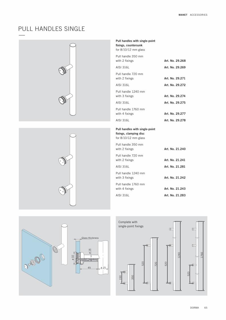
Pull handles with single-point fixings, countersunk for 8/10/12 mm glass
Pull handle 350 mm with 2 fixings
AISI 316L
Pull handle 720 mm with 2 fixings
AISI 316L
Pull handle 1240 mm with 3 fixings
AISI 316L
Pull handle 1760 mm with 4 fixings
AISI 316L
Art. No. 29.268
Art. No. 29.269
Art. No. 29.271
Art. No. 29.272
Art. No. 29.274
Art. No. 29.275
Art. No. 29.277
Art. No. 29.278
Pull handles with single-point fixings, clamping discfor 8/10/12 mm glass
Pull handle 350 mm with 2 fixings
Pull handle 720 mm with 2 fixings
AISI 316L
Pull handle 1240 mm with 3 fixings
Pull handle 1760 mm with 4 fixings
AISI 316L
Art. No. 21.240
Art. No. 21.241
Art. No. 21.281
Art. No. 21.242
Art. No. 21.243
Art. No. 21.283
ø 2545
ø 1
6
ø 3
2
15
0
35
0
52
0
72
0
52
0
12
40
52
0
17
60
Complete with single-point fixings
PULL HANDLES SINGLE—
Glass thickness
DORMA 65
MANET ACCESSORIES

15
0
35
0
52
0
72
0
52
0
12
40
52
0
17
60
Complete incl. connecting bolt
Pair of pull handles incl. connecting bolt for 8/10/12 mm glass
Pair of pull handles 350 mm with 2 fixings
AISI 316L
Pair of pull handles 720 mm with 2 fixings
AISI 316L
Pair of pull handles 1240 mm with 3 fixings
AISI 316L
Pair of pull handles 1760 mm with 4 fixings
AISI 316L
Art. No. 21.267
Art. No. 21.247
Art. No. 21.270
Art. No. 21.250
Art. No. 21.273
Art. No. 21.253
Art. No. 21.276
Art. No. 21.256
7045ø 25
ø 1
6
ø 25
Lockable back-to-back handle bar,for 6 – 16 mm glass1225 mm, with 2 fixings,complete with closing device and cylinder Art. No. 21.279
90
0
12
25
25
42 42
40
20
25
PAIR OF PULL HANDLES—
Glass thickness
Glass thickness
66 DORMA
MANET ACCESSORIES

Art. No. 21.285
Art. No. 21.286
Conversion set 1 for glass doors, pair of pull handles/knob back-to-backdoor thickness 13.5 – 21.5 mm
Glass doorsDoor thickness 13.5 mm: without distance washerDoor thickness 15 mm: with 1 distance washerDoor thickness 17.5 mm: with 2 distance washerDoor thickness 19 mm: with 3 distance washerDoor thickness 21.5 mm: with 4 distance washer
Conversion set 2 for timber doors,pair of pull handles /knob back-to-backdoor thickness 20 – 40 mm
Timber doorsDoor thickness 20 mm: without distance washerDoor thickness 25 mm: with 1 distance washerDoor thickness 30 mm: with 2 distance washerDoor thickness 35 mm: with 3 distance washerDoor thickness 40 mm: with 4 distance washer
Distance washer2 mm
Distance washer5 mm
DOOR KNOBS—
SPACING ADJUSTMENT FOR PULL HANDLES AND DOOR KNOBS—
Door knob one side fixing for 8/10/12 mm glass
Door knob with single-point fixing, countersunk
Door knob with single-point fixings, clamping disc
Door knob back-to-backfor 8/10/12 mm glass
Art. No. 21.422
Art. No. 21.426
Art. No. 21.423
Single-point fixing countersunk
Single-point fixing clamping disc
51
ø 2
5
ø 3
251 51
ø 2
5
Glass thickness
Glass thickness
DORMA 67
MANET ACCESSORIES
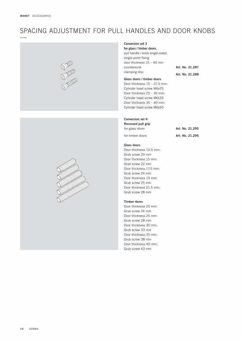
Conversion set 4Recessed pull grip for glass doors
for timber doors
Glass doorsDoor thickness 13.5 mm: Grub screw 20 mm Door thickness 15 mm: Grub screw 22 mm Door thickness 17.5 mm: Grub screw 24 mm Door thickness 19 mm: Grub screw 25 mm Door thickness 21.5 mm: Grub screw 28 mm
Timber doorsDoor thickness 20 mm: Grub screw 24 mm Door thickness 25 mm: Grub screw 28 mmDoor thickness 30 mm: Grub screw 33 mmDoor thickness 35 mm: Grub screw 38 mm Door thickness 40 mm: Grub screw 43 mm
Conversion set 3for glass / timber doors, pull handle / knob single-sided, single-point fixing door thickness 15 – 40 mm countersunkclamping disc
Glass doors / timber doorsDoor thickness 15 – 21.5 mm: Cylinder head screw M6x25Door thickness 25 – 30 mm: Cylinder head screw M6x35Door thickness 35 – 40 mm: Cylinder head screw M6x50
SPACING ADJUSTMENT FOR PULL HANDLES AND DOOR KNOBS—
Art. No. 21.287
Art. No. 21.288
Art. No. 21.295
Art. No. 21.296
68 DORMA
MANET ACCESSORIES

ARCOS pair of pull handlefor 8/10/12 mm glassincl. connecting bolt
only in AISI 316L
Pull handle 350 mmwith 2 fixings
Pull handle 750 mmwith 2 fixings
Art. No. 26.500
Art. No. 26.510Connectingbolt
Bushing
Grub screw
Recessed pull gripØ 50 mm for 8/10/12 mm glass Art. No. 21.290
Recessed pull gripØ 60 mm for 8/10/12 mm glass Art. No. 21.291
Recessed pull grip with grip holeØ 60 mm for 8 mm glass
for 10 mm glass
for 12 mm glass
Art. No. 21.292
Art. No. 21.293
Art. No. 21.294
RECESSED PULL GRIP UND ARCOS PULL HANDLE—
DORMA 69
MANET ACCESSORIES
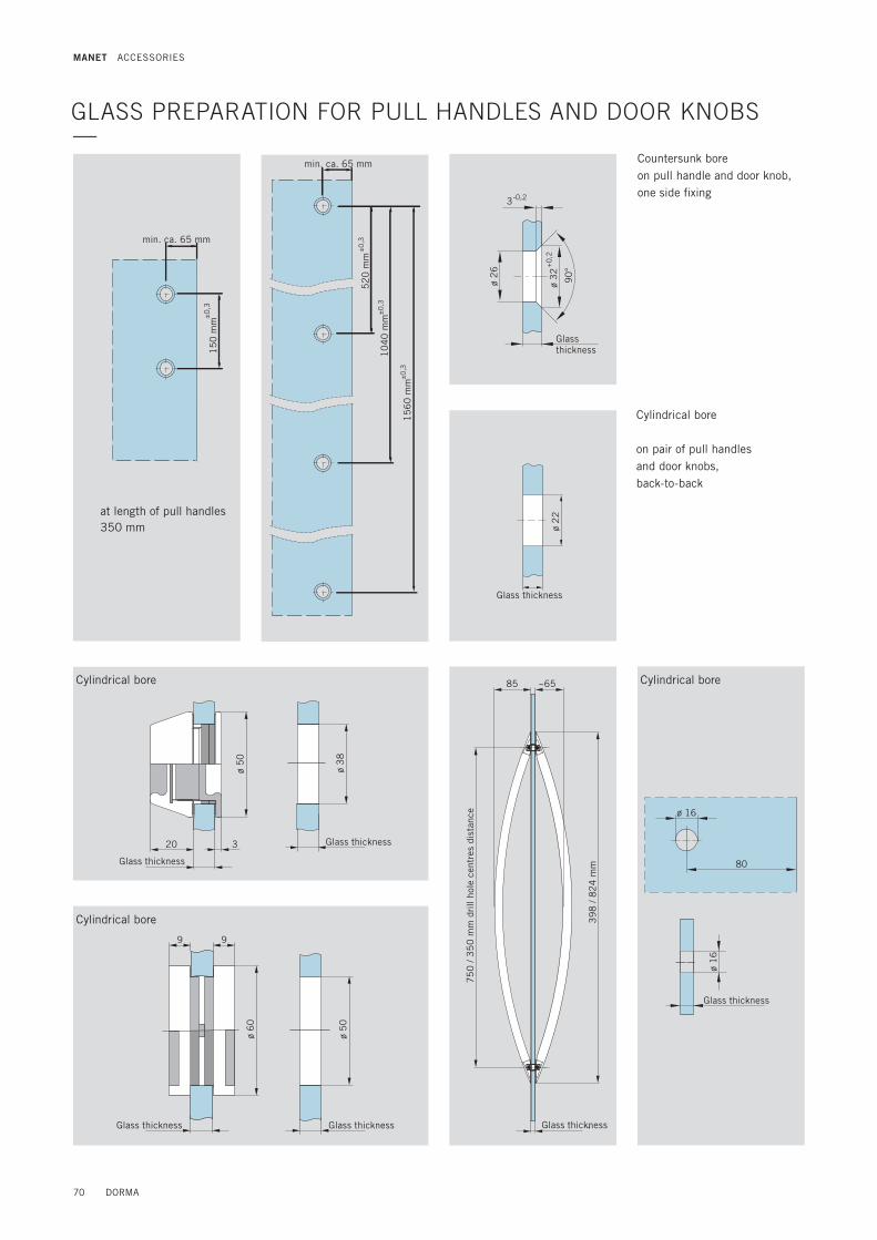
ø 1
6
ø 16
80
Glass thickness
ø 2
6
ø 3
2+0
,2
-0,2
90
°
3
ø 2
2
Countersunk boreon pull handle and door knob,one side fixing
Cylindrical bore
on pair of pull handles and door knobs, back-to-back
85 ~65
39
8 /
82
4 m
m
20 3
ø 5
0
ø 3
8
Cylindrical bore Cylindrical bore
9 9
ø 5
0
ø 6
0
GLASS PREPARATION FOR PULL HANDLES AND DOOR KNOBS—
Cylindrical bore
Glass thickness
Glass thickness
15
0 m
m±0
,3
at length of pull handles350 mm
min. ca. 65 mm
52
0 m
m
10
40
mm
15
60
mm
±0
,3
±0
,3
±0
,3
min. ca. 65 mm
Glass thickness
Glass thickness
Glass thickness Glass thickness Glass thickness
750
/ 3
50
mm
drill
hole
cen
tres
dis
tanc
e
70 DORMA
MANET ACCESSORIES

Clip-on cover for single-point fixing with spring,5 pieces Art. No. 29.217
Assembling tool forMANET Single-point fixing Art. No. 21.134
Assembling tool forMANET single-point fixing(can also be used as attachment for torque wrench)
Art. No. 21.137
Sample case Art. No. 21.995
ACCESSORIES / INSTALLATION TOOLS—
DORMA 71
MANET ACCESSORIES

Subject to change without notice.
For practical planning, please use our drawings DORMA-Glas DETAIL.
PLANNING TOOLS—
For planning of intelligent glass solutions we offer you several planning tools which allow you to create secure and professional solutions for any kinds of glass doors and toughend glass assemblies.
The planning tools MANET COMPACT enable you to prepare designs quickly, reliably and professionally. The software provides you with all necessary documentation such as dimensioned technical drawings, glass sizes and preparation measures.Your benefits: . Easy to operate . Professional and error-free preparation of offers . Rapid response to incoming requests for quotations . Highly reduced planning costs for time and money savings
Mounting1. Only properly qualified and specially trained staff is authorised to
mount DORMA glass fittings.2. Never use glass with conchoidal fractures and/or damaged edges.3. Due to crushing hazards – among others in the area of the
secondary closing edge – and possible injury caused by breakage of glass during mounting, corresponding protective clothing (especially gloves and protective goggles) is required.
4. Clean clamping area with fat solvent (standard commercial cleaning agent) before mounting the glass fitting.
5. Never use clamping shoes on structured glass surfaces (except on satined glass) or glass of heavily varying thickness unless with a corresponding levelling layer.
6. Never use clamping shoes on self-cleaning coatings.
7. When adjusting glass elements, always stick to the required clearance for the respective fitting. Adjust clearance so that the glass does not touch hart components such as glass, metal or concrete.
8. Make sure not to use excessive force when installing the glass (avoid local stress resulting from very tight screws).
Maintenance Check fittings at regular intervals for proper positioning and smooth running and door for correct adjustment. Especially highly- frequented door systems require inspection by properly qualified staff (specialised companies or installation firms). Immediately replace damaged class elements (no glass flaking and/or conchoidal fractures)!
Important safety-related information for the mounting and use of DORMA glass fittings (Follow these instructions in addition to the mounting and operating instructions in order to avoid damage of product and damage to person or property.)Important: All users have to be informed about relevant points mentioned in these safety-related information and the mounting and operating instructions!
General information1. DORMA recommends using TSG-H (heat soaked toughened safety
glass) to DIN EN 12150-1.2. DORMA glass fittings are not suitable for application in rooms
where chemicals (e. g. chlorine) are used such as indoor swim-ming pools, saunas or salt-water pools.
3. Never move sliding panels faster than walking speed and always stop the door manually before it reaches end position.
4. Do not shut swing doors with excessive force. Install door stop to prevent door from opening too far.
SAFETY-RELATED INFORMATION —
72 DORMA
MANET GENERAL

DORMA 73

74 DORMA

DORMA 75

DORMA GmbH + Co. KGDORMA Platz 158256 ENNEPETALGERMANYPhone +49 2333 793-0Fax +49 2333 793-4950www.dorma.com
DORMA-Glas GmbH Max-Planck-Straße 33–45 32107 BAD SALZUFLENGERMANY Phone +49 5222 924-100 Fax +49 5222 924-3100www.dorma.com
WN
05
41
50
51
53
2 ·
04
/13
· G
B ·
XX
· x
· xx
/13