single-view 3d reconstruction - university of illinois at … · 2017-10-12 · single-view 3d...
TRANSCRIPT

Single-view 3D Reconstruction
Computational Photography
Derek Hoiem, University of Illinois
10/12/17
Some slides from Alyosha Efros, Steve Seitz

Notes about Project 4 (Image-based Lighting)
• You can work with a partner and submit a joint project
• You will need a mirrored sphere (see Piazza post)
– I have a few which I will be able to loan out for a couple days at a time, but I’d like to reserve them for emergencies
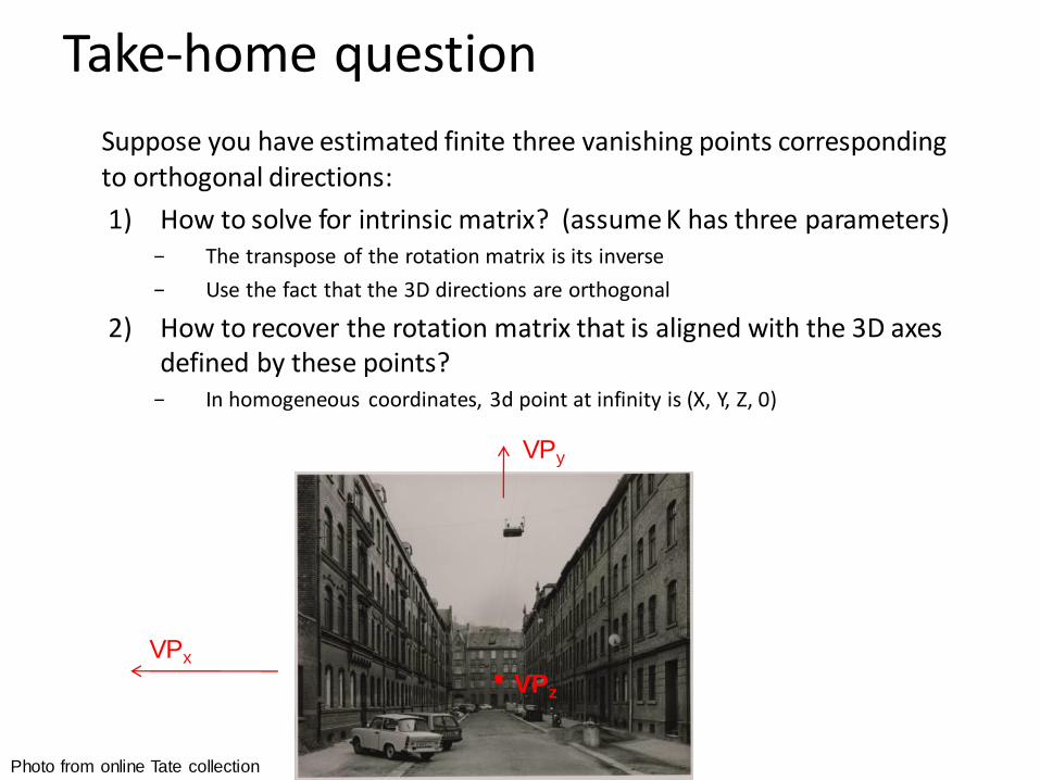
Suppose you have estimated finite three vanishing points corresponding to orthogonal directions:
1) How to solve for intrinsic matrix? (assume K has three parameters)− The transpose of the rotation matrix is its inverse
− Use the fact that the 3D directions are orthogonal
2) How to recover the rotation matrix that is aligned with the 3D axes defined by these points?
− In homogeneous coordinates, 3d point at infinity is (X, Y, Z, 0)
Photo from online Tate collection
VPx
VPz.
VPy
Take-home question

Take-home question
Assume that the man is 6 ft tall.
– What is the height of the front of the building?
– What is the height of the camera?

Take-home question
Assume that the man is 6 ft tall.
– What is the height of the front of the building?
– What is the height of the camera?
1.55
0.92
(0.92+1.55)/1.55*6=9.56
~5’7


Focal length, aperture, depth of field
• Increase in focal length “zooms in”, decreasing field of view (and light per pixel), increasing depth of field (less blur)
• Increase in aperture lets more light in but decreases depth of field
focal point
F
optical center
(Center Of Projection)
Slide source: Seitz
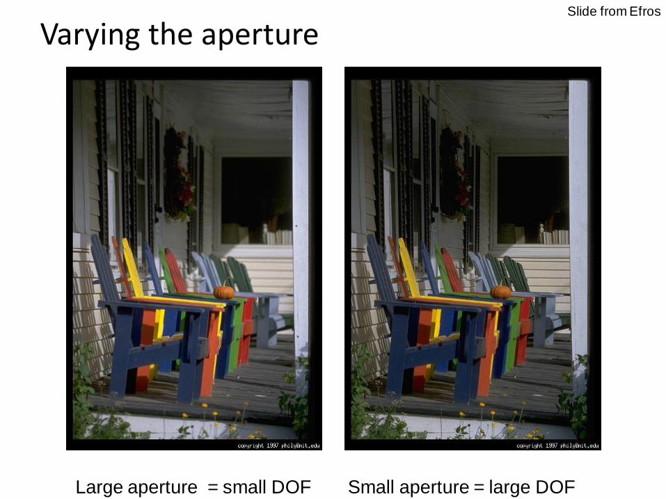
Varying the aperture
Large aperture = small DOF Small aperture = large DOF
Slide from Efros
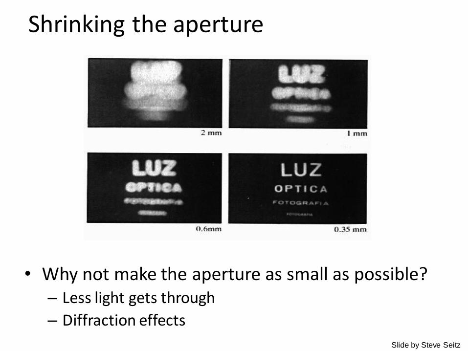
Shrinking the aperture
• Why not make the aperture as small as possible?– Less light gets through
– Diffraction effects
Slide by Steve Seitz
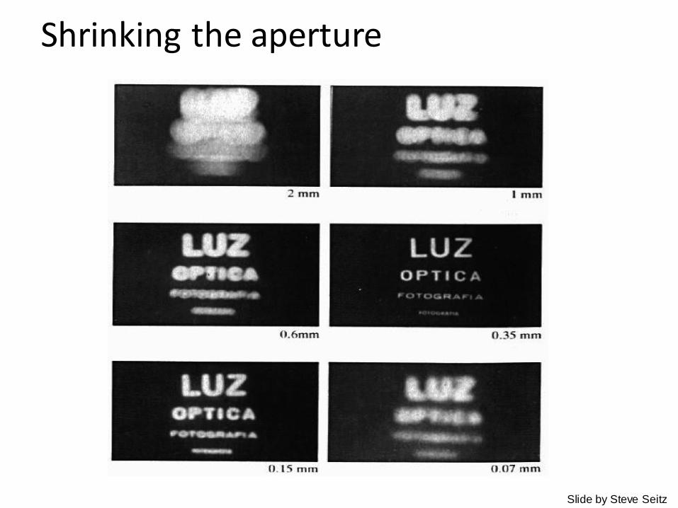
Shrinking the aperture
Slide by Steve Seitz
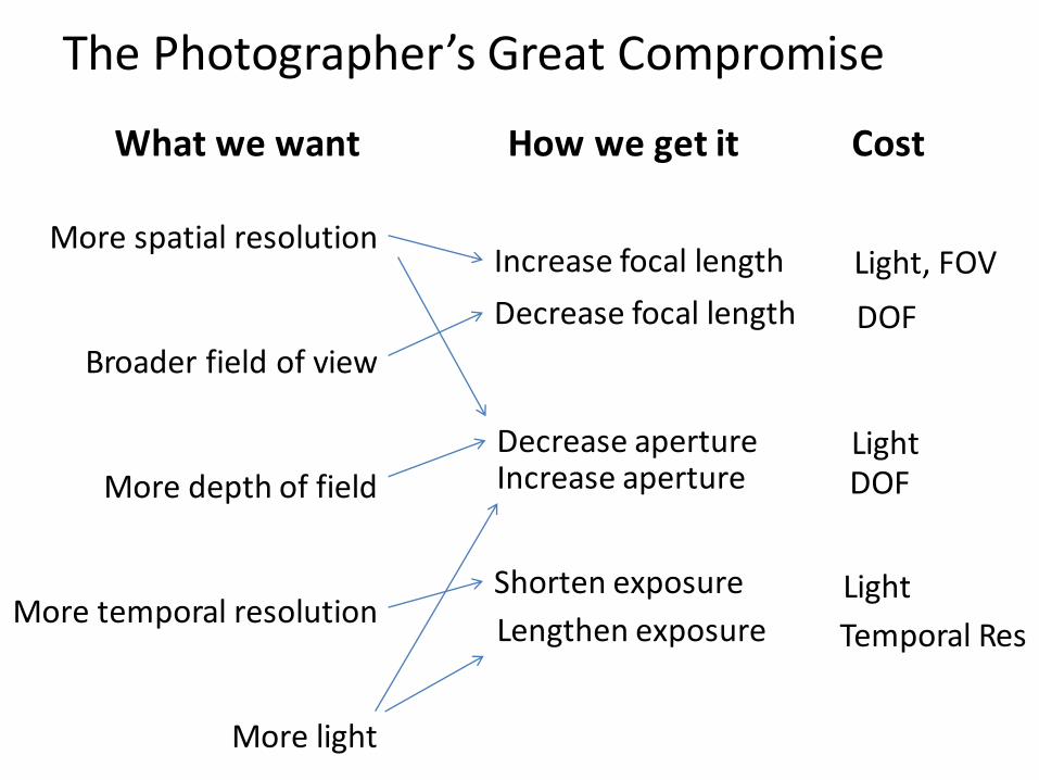
The Photographer’s Great Compromise
What we want
More spatial resolution
Broader field of view
More depth of field
More temporal resolution
More light
How we get it
Increase focal length
Decrease aperture
Shorten exposure
Lengthen exposure
Increase aperture
Decrease focal length
Cost
Light, FOV
DOF
LightDOF
Light
Temporal Res

Difficulty in macro (close-up) photography
• For close objects, we have a small relative DOF
• Can only shrink aperture so far
How to get both bugs in focus?

Solution: Focus stacking
1. Take pictures with varying focal length
http://www.wonderfulphotos.com/articles/macro/focus_stacking/
Example from

Solution: Focus stacking
1. Take pictures with varying focal length
2. Combine
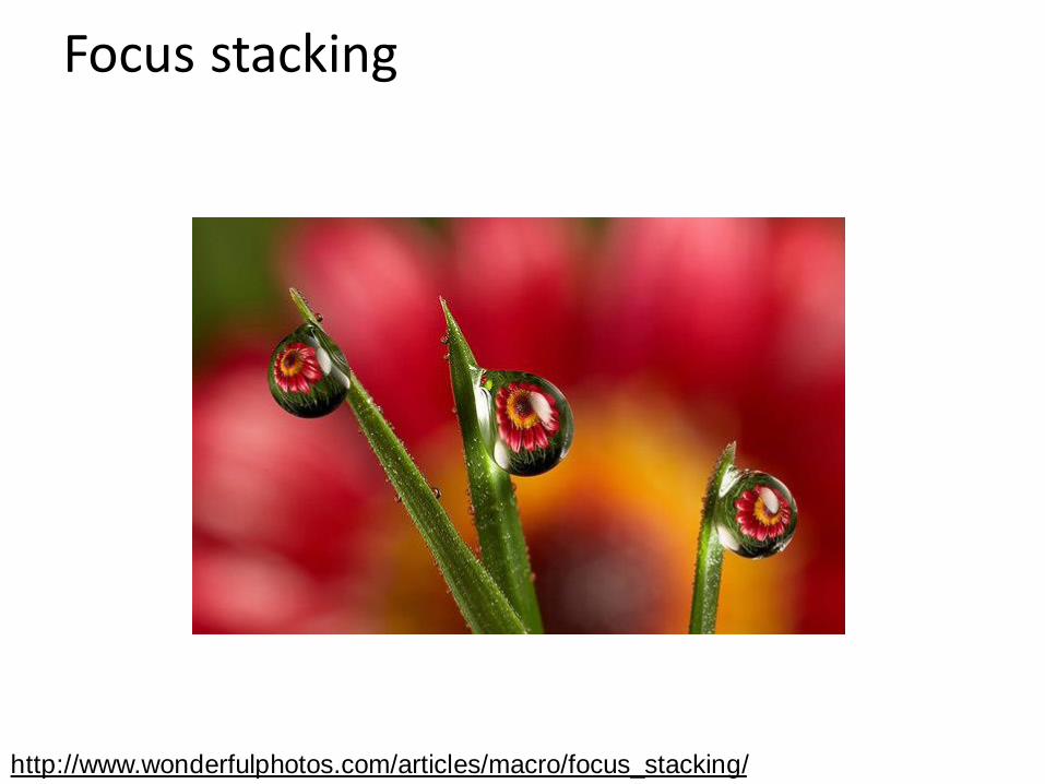
Focus stacking
http://www.wonderfulphotos.com/articles/macro/focus_stacking/

Focus stacking
How to combine?
1. Align images (e.g., using corresponding points)
2. Two ideas
a) Mask regions by hand and combine with pyramid blend
b) Gradient domain fusion (mixed gradient) without masking
http://www.zen20934.zen.co.uk/photograph
y/Workflow.htm#Focus%20Stacking
Automatic solution would make a
good final project
http://www.digital-photography-
school.com/an-introduction-to-focus-
stacking
Recommended Reading:

Relation between field of view and focal length
Field of view (angle width) Film/Sensor Width
Focal lengthfdfov
2tan2 1

Dolly Zoom or “Vertigo Effect”
http://www.youtube.com/watch?v=NB4bikrNzMk
http://en.wikipedia.org/wiki/Focal_length
Zoom in while
moving away
How is this done?

Dolly zoom (or “Vertigo effect”)
Distance between object and camera
width of object
Field of view (angle width) Film/Sensor Width
Focal lengthfdfov
2tan2 1
distancetan2
2
widthfov

Today’s class: 3D Reconstruction

The challenge
One 2D image could be generated by an infinite number of 3D geometries
?
?
?

The solution
Make simplifying assumptions about 3D geometry
Unlikely Likely
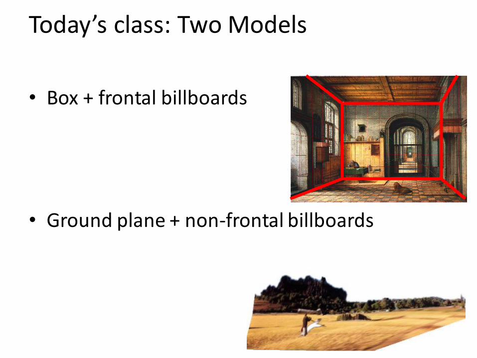
Today’s class: Two Models
• Box + frontal billboards
• Ground plane + non-frontal billboards

“Tour into the Picture” (Horry et al. SIGGRAPH ’97)
Create a 3D “theatre stage” of five billboards
Specify foreground objects through bounding polygons
Use camera transformations to navigate through the scene
Following slides modified from Efros
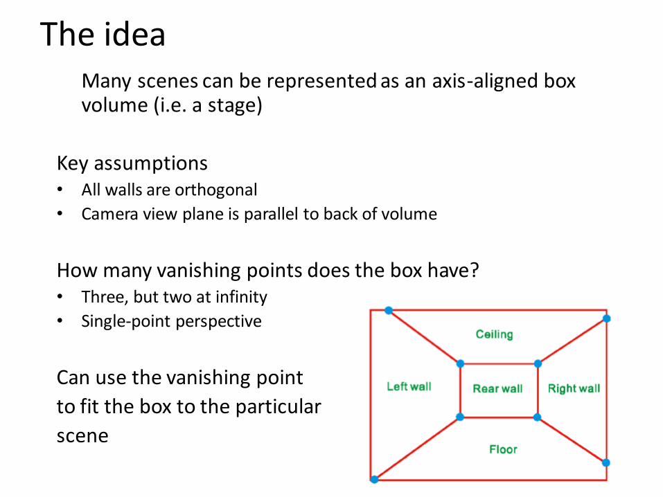
The ideaMany scenes can be represented as an axis-aligned box volume (i.e. a stage)
Key assumptions• All walls are orthogonal
• Camera view plane is parallel to back of volume
How many vanishing points does the box have?• Three, but two at infinity
• Single-point perspective
Can use the vanishing point
to fit the box to the particular
scene

Step 1: specify scene geometry
• User controls the inner box and the vanishing point placement (# of DOF?)
• Q: What’s the significance of the vanishing point location?
• A: It’s at eye (camera) level: ray from center of projection to VP is perpendicular to image plane– Under single-point perspective assumptions, the VP
should be the principal point of the image

High
Camera
Example of user input: vanishing point and back face of
view volume are defined

Low
Camera
Example of user input: vanishing point and back face of
view volume are defined

High Camera Low Camera
Comparison of how image is subdivided based on two
different camera positions. You should see how moving
the box corresponds to moving the eyepoint in the 3D
world.

Left
Camera
Another example of user input: vanishing point and back
face of view volume are defined

Right
Camera
Another example of user input: vanishing point and back
face of view volume are defined

Left Camera Right Camera
Comparison of two camera placements – left and right.
Corresponding subdivisions match view you would see if
you looked down a hallway.

Question
• Think about the camera center and image plane…
– What happens when we move the box?
– What happens when we move the vanishing point?

2D to 3D conversion
• First, we can get ratios
left right
top
bottom
vanishing
point
back
plane

Size of user-defined back plane determines
width/height throughout box (orthogonal sides)
Use top versus side ratio
to determine relative
height and width
dimensions of box
Left/right and top/bot
ratios determine part of
3D camera placement
left right
top
bottomcamera
pos
2D to 3D conversion

Depth of the box
• Can compute by similar triangles (CVA vs. CV’A’)• Need to know focal length f (or FOV)
• Note: can compute position on any object on the ground– Simple unprojection– What about things off the ground?

Step 2: map image textures into frontal view
A
B
C
D
A’B’
C’ D’
2d coordinates3d plane coordinates

Image rectification
To unwarp (rectify) an image solve for homography H
given p and p’: wp’=Hp
pp’

Computing homography
Assume we have four matched points: How do we compute homography H?
Direct Linear Transformation (DLT)
Hpp '
0h
vvvvuvu
uuvuuvu
1000
0001
'
''
''
'
w
vw
uw
p
987
654
321
hhh
hhh
hhh
H
9
8
7
6
5
4
3
2
1
h
h
h
h
h
h
h
h
h
h

Computing homography
Direct Linear Transform
• Apply SVD: USVT = A
• h = Vsmallest (column of VT corr. to smallest singular value)
987
654
321
9
2
1
hhh
hhh
hhh
h
h
h
Hh
0Ah0h
nnnnnnn vvvvuvu
vvvvuvu
uuvuuvu
1000
1000
0001
1111111
1111111
Matlab[U, S, V] = svd(A);
h = V(:, end);
Explanation of SVD, solving systems of linear equations, derivation of solution here

Solving for homographies (more detail)
A h 0
Defines a least squares problem:
2n × 9 9 2n
• Since h is only defined up to scale, solve for unit vector ĥ
• Solution: ĥ = eigenvector of ATA with smallest eigenvalue
• Can derive using Lagrange multipliers method
• Works with 4 or more points
note: (x,y) is used in place of (u,v) here

Tour into the picture algorithm
1. Set the box corners

Tour into the picture algorithm
1. Set the box corners
2. Set the VP
3. Get 3D coordinates– Compute height,
width, and depth of box
4. Get texture maps– homographies for
each face
5. Create file to store plane coordinates and texture maps
x

Result
Render from new views
http://www.cs.cmu.edu/afs/cs.cmu.edu/academic/class/15463-f08/www/proj5/www/dmillett/

Foreground Objects
Use separate billboard for each
For this to work, three separate images used:
– Original image.
– Mask to isolate desired foreground images.
– Background with objects removed

Foreground Objects
Add vertical rectangles for each foreground object
Can compute 3D coordinates P0, P1 since they are on known plane.
P2, P3 can be computed as before (similar triangles)

Foreground Result
Video from CMU class:
http://www.youtube.com/watch?v=dUAtd
mGwcuM

Automatic Photo Pop-up
Input
Ground
Vertical
Sky
Geometric Labels Cut’n’Fold 3D Model
Image
Learned Models
Hoiem et al. 2005

Cutting and Folding
• Fit ground-vertical boundary– Iterative Hough transform

Cutting and Folding
• Form polylines from boundary segments– Join segments that intersect at slight angles
– Remove small overlapping polylines
• Estimate horizon position from perspective cues

Cutting and Folding
• ``Fold’’ along polylines and at corners
• ``Cut’’ at ends of polylines and along vertical-sky boundary

Cutting and Folding
• Construct 3D model
• Texture map

Results
Automatic Photo Pop-up
Input Image
Cut and Fold
http://www.cs.illinois.edu/homes/dhoiem/projects/popup/

Results
Automatic Photo Pop-upInput Image

Comparison with Manual Method
Input Image
Automatic Photo Pop-up (15 sec)!
[Liebowitz et al. 1999]

Failures
Labeling Errors
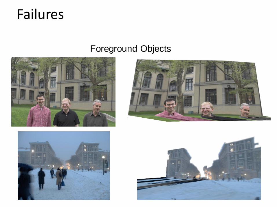
Failures
Foreground Objects

Adding Foreground Labels
Recovered Surface Labels +
Ground-Vertical Boundary Fit
Object Boundaries + Horizon


Fitting boxes to indoor scenes
Wall
Sofa
Floor
Table

Box Layout Algorithm
1. Detect edges
2. Estimate 3 orthogonal vanishing points
3. Apply region classifier to label pixels with visible surfaces– Boosted decision trees on region based on color, texture,
edges, position
4. Generate box candidates by sampling pairs of rays from VPs
5. Score each box based on edges and pixel labels– Learn score via structured learning
6. Jointly refine box layout and pixel labels to get final estimate
+
Hedau et al. 2010

Experimental results
Detected Edges Surface Labels Box Layout
Detected Edges Surface Labels Box Layout

Experimental results
Detected Edges Surface Labels Box Layout
Detected Edges Surface Labels Box Layout

Complete 3D from RGBD
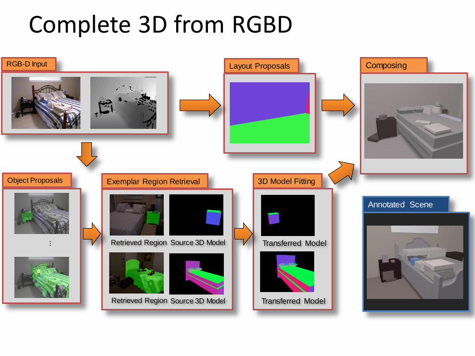
Object Proposals
... Retrieved Region
Exemplar Region Retrieval
Source 3D Model
Retrieved Region Source 3D Model
Layout Proposals
3D Model Fitting
Transferred Model
Transferred Model
RGB-D Input
Annotated Scene
Composing
Complete 3D from RGBD

Complete 3D from RGBD

Final project ideas
• If a one-person project:
– Interactive program to make 3D model from an image (e.g., output in VRML, or draw path for animation)
• If a two-person team, 2nd person:
– Add tools for cutting out foreground objects and automatic hole-filling

Summary
• 2D3D is mathematically impossible(but we do it without even thinking)
• Need right assumptions about the world geometry
• Important tools– Vanishing points
– Camera matrix
– Homography

Next Week
• Project 3 is due Monday
• Next three classes: image-based lighting
– How to model light
– Recover HDR image from multiple LDR images
– Recover lighting model from an image
– Render object into a scene with correct lighting and geometry