single-wall, flat oval founded in 1951 duct and …single-wall flat oval duct and fittings are also...
TRANSCRIPT

An enterprise of United McGill Corporation -Founded in 1951
One Mission ParkGroveport, Ohio 43125-1149614/836-9981, Fax: 614/836-9843E-mail: [email protected] site: http://www.mcgillairflow.com
Single-Wall, Flat OvalDuct and F itt ingsDimensions
Table 1 - Single-wall, Flat Oval Duct - Available Materials and Thicknesses1
Construction Lengths2 Materials3 Thicknesses 6
UNI-SEAL™ Duct(spiral lockseam)
1-12 feet
Galvanized Steel 26-18 gauge
Stainless Steel 26-20 gauge
Aluminum 0.025-0.063 inch4
Long itudinalSeam Duct
(solid welded)
1-6 feetGalvanized Steel 20-10 gauge
Stainless Steel 22-10 gauge
Aluminum 0.040-0.090 inch4
Table 2 - Single-wall, Flat Oval Fittings- Available Materials and Thicknesses1
Construction Materials3 Thicknesses
UNI-SEAL Fittings5
(spot welded and bonded, or standingseam)
Galvanized Steel 26-10 gauge
Stainless Steel 26-10 gauge
Aluminum 0.032-0.090 inch4
1. Standard McGill AirFlow single-wall flat oval duct and fittings are available in the dimensions shown in Table 5.2. Some standard lengths of UNI-SEAL, flat oval duct are only available in 6-foot lengths; longer lengths are available on
special order. Standard lengths of longitudinal seam duct are 5 and 6 feet.3. Single-wall flat oval duct and fittings are also available in carbon steel, paintable galvanized steel, and aluminized
steel.4. Aluminum single-wall flat oval duct and fittings are available in larger sizes and greater metal thicknesses on special
order.5. Fittings 16 gauge (Aluminum - 0.090 inch) or heavier are fully welded.6. See Table 3 for a full range of available spiral flat oval sizes by gauge.
© 2001 McGill AirFlow Corporation

Duct Construction
Spiral Lockseam Longitudinal Seam
Table 3 - Available Range of Spiral Duct Basic Round Diameter Used to Fabricate Spiral Flat Oval Duct by Thickness1
Gauge
Galvanized Steel, Aluminized Steeland
Nongalvanized Carbon Steel
Stainless Steel(304, 304L, 316 and 316L)
Aluminum2
Spiral Lockseam Basic Round
Diameter(inches)
Spiral Lockseam Basic Round
Diameter(inches)
Thickness(inches)
Spiral LockseamBasic Round
Diameter(inches)
282624222018
6 - 14 1/26 - 266 - 366 - 506 - 606 - 64
N/AN/A
6 - 506 - 606 - 64N/A
0.0400.0500.063
6 - 606 - 606 - 60
1 Thicker material may be available in some basic round diameter ranges; check with your local sales office.2 Aluminum single-wall, round, spiral duct is available in larger basic round diameters on special order.
2

Fitting Construction
Solid Welded Spot Welded, Tack Weldedor Mechanical Fastened
Sealed with United Duct Sealer™ (Water Based) or UNI-WELD™ weld sealant
Standing Seam Resistance Seam Welded
Sealed with United Duct Sealer (Water Based) or UNI-WELD weld sealant
Sealed with United Duct Sealer (Water Based) or UNI-WELD weld sealant
Dimensioning
(All alphanumeric dimensions are in inches, all angles are in degrees)
A - Main barrel inlet major axisa - Main barrel inlet minor axisB - Main barrel outlet major axisb - Main barrel outlet minor axisC or D - Branch tap major axis (Note: On tee and lateral fittings with two taps, C is the branch
closest to the inlet of the fitting. On cross fittings, C is the larger of the two taps.)c or d - Branch tap minor axist - Insulation/liner thicknessR - Centerline radiusS - Slip-fit dimension of a fittingF, H, J, L, Q, V, Z, m, . - Miscellaneous dimensions (refer to specific drawings)� or 3 - Angular measurements (refer to specific drawings)# - Number of elbow gores
3

General Notes: • Dimensions other than minor and major axes are held within a ¼ inch tolerance.• The major axis is the greater dimension; the minor axis is the smaller dimension.
• Unless ordered otherwise, single-wall, flat oval fittings are sized to slip fit into single-wall, flat oval duct.• Single-wall fittings ordered for 2-inch slip-fit assembly have a slip-fit section as shown in the following drawing:
Where: S = 2 inches
• Single-wall duct and fittings can be ordered with Van Stone or applied connectors. Van Stone and appliedconnectors change the makeup dimensions of standard slip-fit dimension ends. Refer to the details on page 46 forfurther information.
• Unless ordered otherwise, the branch taps of laterals, crosses, lateral crosses, and Y-fittings are installed atstandard angles to the fittings' bodies and to each other, as shown in the following drawings:
For all :Laterals, � standard = 45(Crosses, � standard = 90(, 3 standard = 180(Lateral Crosses, � standard = 45(, 3 standard = 180(Y-Fittings, � standard = 90(
Note: 3 is the included angle between taps as viewed in cross section (standard is 180(). When ordering fittings ofnonstandard 3, please include an end view.
4
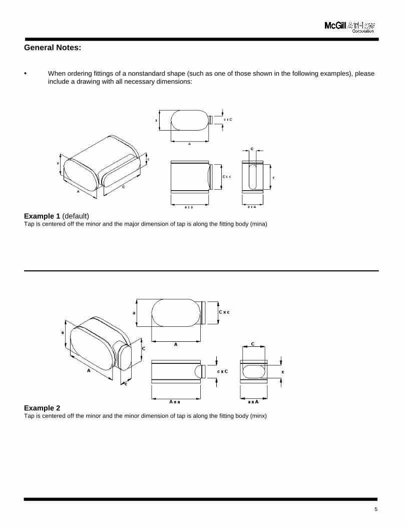
General Notes:
• When ordering fittings of a nonstandard shape (such as one of those shown in the following examples), pleaseinclude a drawing with all necessary dimensions:
Example 1 (default)Tap is centered off the minor and the major dimension of tap is along the fitting body (mina)
Example 2Tap is centered off the minor and the minor dimension of tap is along the fitting body (minx)
5

Example 3Tap is centered off the major and the major dimension of tap is along the fitting body (maja)
Example 4Tap is centered off the major and the minor dimension of tap is along the fitting body (majx)
Example 5 Example 6Tap is not centered on the major axis; Tap is not centered on the minor axis; specify dimension shown specify dimension shown
6
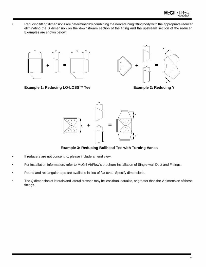
• Reducing fitting dimensions are determined by combining the nonreducing fitting body with the appropriate reducereliminating the S dimension on the downstream section of the fitting and the upstream section of the reducer.Examples are shown below:
Example 1: Reducing L O-LOSS™ Tee Example 2: Reducing Y
Example 3: Reducing Bullhead Tee with Turning Vanes
• If reducers are not concentric, please include an end view.
• For installation information, refer to McGill AirFlow’s brochure Installation of Single-wall Duct and Fittings.
• Round and rectangular taps are available in lieu of flat oval. Specify dimensions.
• The Q dimension of laterals and lateral crosses may be less than, equal to, or greater than the V dimension of thesefittings.
7

Designations:
McGill AirFlow uses a designation system that simplifies product nomenclature. Most of our products can beaccurately identified using a concise alphanumeric designator. Each character in the designation defines acharacteristic of the product.
Example: SOST refers to a single-wall (S), oval (O), standard gauge (S), straight tee (T).
1st Character: Wall Configuration - SOST
S = Single-wallK = k27 Double-wall
2nd Character: Shape - SOST
R = RoundO = Oval
3rd Character: Product Line - SOST
S = Standard gauge of product type N = Nonstandard gauge (user specified)
Notes: 1. When ordering duct or fittings, specify S or N in the * position of the designation.
4th and Subsequent Characters: Product Type - SOST
T = Straight Tee (90( branch fitting)
8

Table 4 - Thickness/Weight Relationships of Standard Materials
Gauge
Galvanized and Paintable GalvanizedSteel
Nongalvanized Carbon Steel Stainless Steel(304 or 316)
MinimumThickness(inches)
NominalThickness(inches)
NominalWeight
(lb/sq ft)
MinimumThickness(inches)
NominalThickness(inches)
NominalWeight
(lb/sq ft)
MinimumThickness(inches)
NominalThickness(inches)
NominalWeight
(lb/sq ft)
28262422201816141210
0.01570.01870.02360.02960.03560.04660.05750.07050.09940.1292
0.01870.02170.02760.03360.03960.05160.06350.07850.10840.1382
0.7810.9061.1561.4061.6562.1562.6563.2814.5315.781
0.01290.01590.02090.02690.03290.04380.05480.06970.09860.1285
0.01490.01790.02390.02990.03590.04780.05980.07470.10460.1345
0.6250.7501.0001.2501.5002.0002.5003.1254.3755.625
0.01360.01580.02200.02730.03350.04500.05650.07110.10000.1286
0.01560.01880.02500.03130.03750.05000.06250.07810.10940.1406
0.6560.7881.0501.3131.5752.1002.6253.2814.5945.906
Aluminum3003-H14
MinimumThickness(inches)
NominalThickness(inches)
NominalWeight
(lb/sq ft)
0.02300.02950.03650.04650.05950.07550.08550.09450.1195
0.0250.0320.0400.0500.0630.0800.0900.1000.125
0.3560.4560.5700.7130.8981.1401.2831.4261.782
9
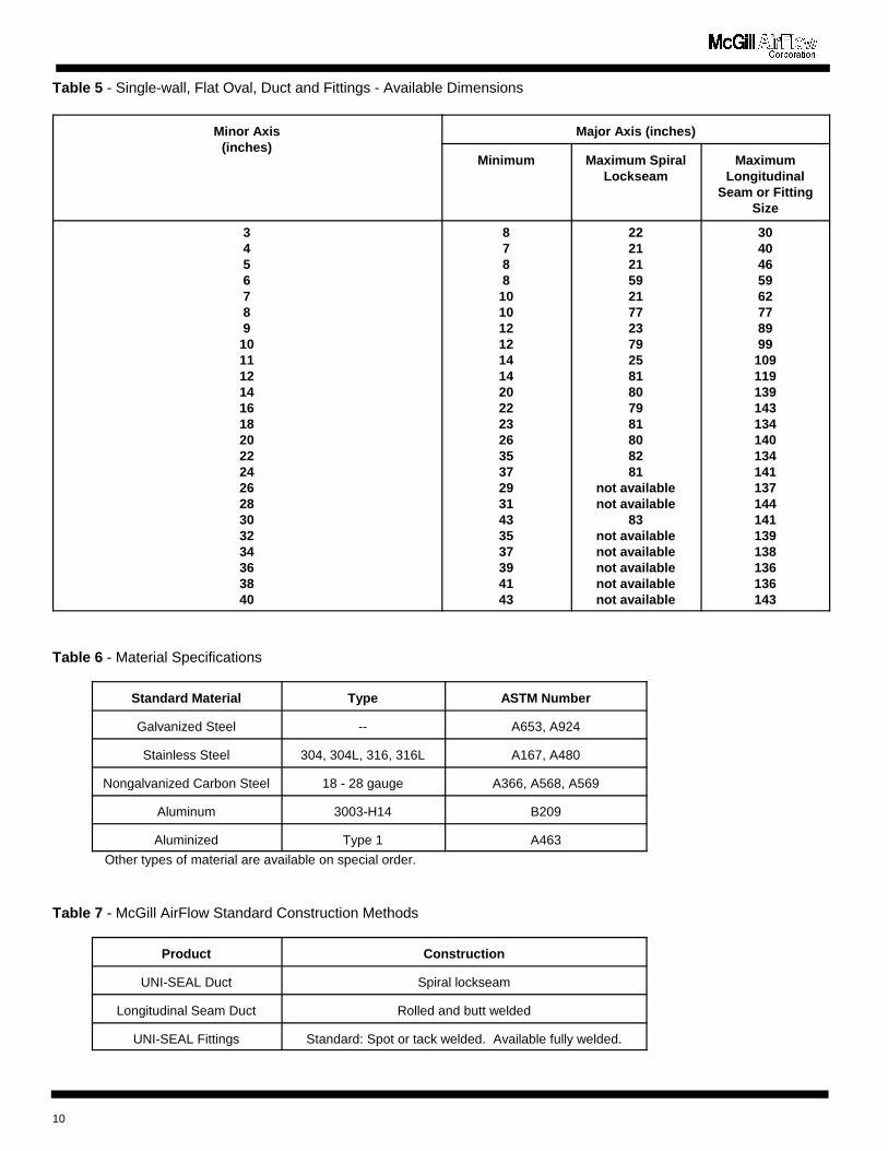
Table 5 - Single-wall, Flat Oval, Duct and Fittings - Available Dimensions
Minor Axis(inches)
Major Axis (inches)
Minimum Maximum SpiralLockseam
MaximumLongitudinal
Seam or FittingSize
3456789
1011121416182022242628303234363840
8788
1010121214142022232635372931433537394143
22212159217723792581807981808281
not availablenot available
83not availablenot availablenot availablenot availablenot available
3040465962778999
109119139143134140134141137144141139138136136143
Table 6 - Material Specifications
Standard Material Type ASTM Number
Galvanized Steel -- A653, A924
Stainless Steel 304, 304L, 316, 316L A167, A480
Nongalvanized Carbon Steel 18 - 28 gauge A366, A568, A569
Aluminum 3003-H14 B209
Aluminized Type 1 A463
Other types of material are available on special order.
Table 7 - McGill AirFlow Standard Construction Methods
Product Construction
UNI-SEAL Duct Spiral lockseam
Longitudinal Seam Duct Rolled and butt welded
UNI-SEAL Fittings Standard: Spot or tack welded. Available fully welded.
10
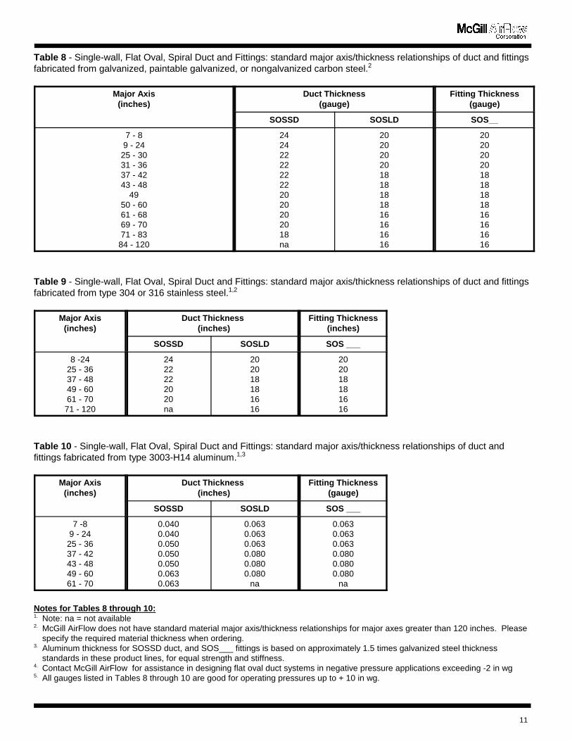
Table 8 - Single-wall, Flat Oval, Spiral Duct and Fittings: standard major axis/thickness relationships of duct and fittingsfabricated from galvanized, paintable galvanized, or nongalvanized carbon steel.2
Major Axis(inches)
Duct Thickness(gauge)
Fitting Thickness(gauge)
SOSSD SOSLD SOS__
7 - 89 - 24
25 - 3031 - 3637 - 4243 - 48
4950 - 6061 - 6869 - 7071 - 83
84 - 120
2424222222222020202018na
202020201818181816161616
202020201818181816161616
Table 9 - Single-wall, Flat Oval, Spiral Duct and Fittings: standard major axis/thickness relationships of duct and fittingsfabricated from type 304 or 316 stainless steel.1,2
Major Axis(inches)
Duct Thickness (inches)
Fitting Thickness(inches)
SOSSD SOSLD SOS ___
8 -2425 - 3637 - 4849 - 6061 - 70
71 - 120
2422222020na
202018181616
202018181616
Table 10 - Single-wall, Flat Oval, Spiral Duct and Fittings: standard major axis/thickness relationships of duct andfittings fabricated from type 3003-H14 aluminum.1,3
Major Axis(inches)
Duct Thickness (inches)
Fitting Thickness(gauge)
SOSSD SOSLD SOS ___
7 -89 - 24
25 - 3637 - 4243 - 4849 - 6061 - 70
0.0400.0400.0500.0500.0500.0630.063
0.0630.0630.0630.0800.0800.080
na
0.0630.0630.0630.0800.0800.080
na
Notes for Tables 8 through 10:1. Note: na = not available2. McGill AirFlow does not have standard material major axis/thickness relationships for major axes greater than 120 inches. Please
specify the required material thickness when ordering.3. Aluminum thickness for SOSSD duct, and SOS___ fittings is based on approximately 1.5 times galvanized steel thickness
standards in these product lines, for equal strength and stiffness.4. Contact McGill AirFlow for assistance in designing flat oval duct systems in negative pressure applications exceeding -2 in wg 5. All gauges listed in Tables 8 through 10 are good for operating pressures up to + 10 in wg.
11
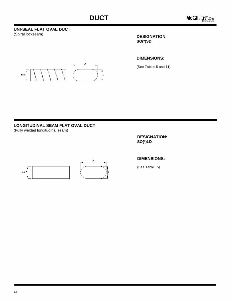
DESIGNATION:SO(*)SD
DIMENSIONS:
(See Tables 5 and 11)
DESIGNATION:SO(*)LD
DIMENSIONS:
(See Table 5)
DUCT
UNI-SEAL FLAT OVAL DUCT(Spiral lockseam)
LONGITUDINAL SEAM FLAT OVAL DUCT(Fully welded longitudinal seam)
12
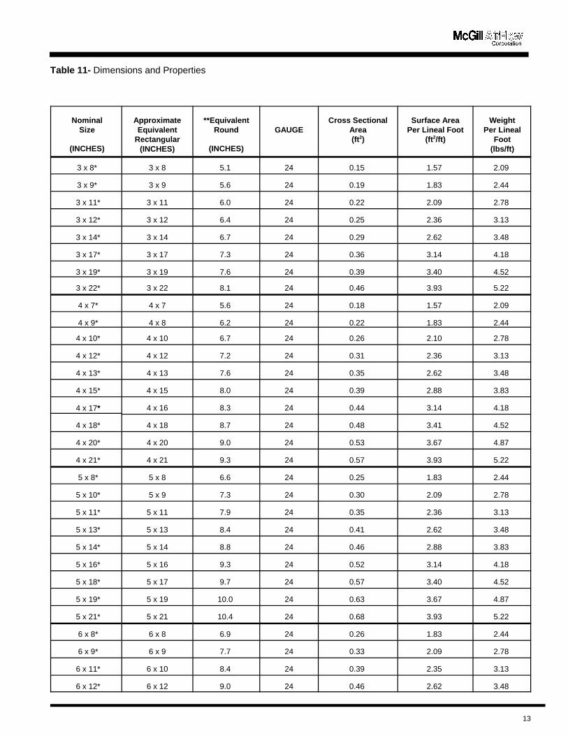
Table 11- Dimensions and Properties
13
NominalSize
(INCHES)
ApproximateEquivalent
Rectangular(INCHES)
**EquivalentRound
(INCHES)
GAUGECross Sectional
Area(ft2)
Surface AreaPer Lineal Foot
(ft2/ft)
WeightPer Lineal
Foot(lbs/ft)
3 x 8* 3 x 8 5.1 24 0.15 1.57 2.09
3 x 9* 3 x 9 5.6 24 0.19 1.83 2.44
3 x 11* 3 x 11 6.0 24 0.22 2.09 2.78
3 x 12* 3 x 12 6.4 24 0.25 2.36 3.13
3 x 14* 3 x 14 6.7 24 0.29 2.62 3.48
3 x 17* 3 x 17 7.3 24 0.36 3.14 4.18
3 x 19* 3 x 19 7.6 24 0.39 3.40 4.52
3 x 22* 3 x 22 8.1 24 0.46 3.93 5.22
4 x 7* 4 x 7 5.6 24 0.18 1.57 2.09
4 x 9* 4 x 8 6.2 24 0.22 1.83 2.44
4 x 10* 4 x 10 6.7 24 0.26 2.10 2.78
4 x 12* 4 x 12 7.2 24 0.31 2.36 3.13
4 x 13* 4 x 13 7.6 24 0.35 2.62 3.48
4 x 15* 4 x 15 8.0 24 0.39 2.88 3.83
4 x 17* 4 x 16 8.3 24 0.44 3.14 4.18
4 x 18* 4 x 18 8.7 24 0.48 3.41 4.52
4 x 20* 4 x 20 9.0 24 0.53 3.67 4.87
4 x 21* 4 x 21 9.3 24 0.57 3.93 5.22
5 x 8* 5 x 8 6.6 24 0.25 1.83 2.44
5 x 10* 5 x 9 7.3 24 0.30 2.09 2.78
5 x 11* 5 x 11 7.9 24 0.35 2.36 3.13
5 x 13* 5 x 13 8.4 24 0.41 2.62 3.48
5 x 14* 5 x 14 8.8 24 0.46 2.88 3.83
5 x 16* 5 x 16 9.3 24 0.52 3.14 4.18
5 x 18* 5 x 17 9.7 24 0.57 3.40 4.52
5 x 19* 5 x 19 10.0 24 0.63 3.67 4.87
5 x 21* 5 x 21 10.4 24 0.68 3.93 5.22
6 x 8* 6 x 8 6.9 24 0.26 1.83 2.44
6 x 9* 6 x 9 7.7 24 0.33 2.09 2.78
6 x 11* 6 x 10 8.4 24 0.39 2.35 3.13
6 x 12* 6 x 12 9.0 24 0.46 2.62 3.48
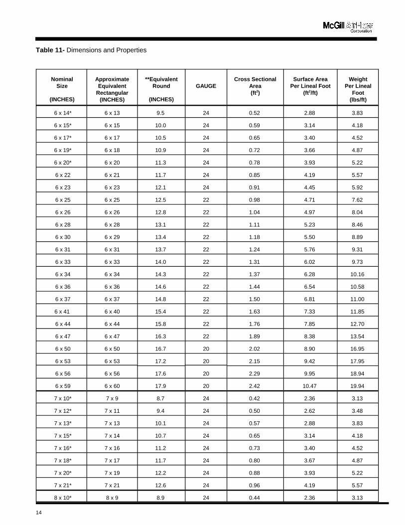
Table 11- Dimensions and Properties
NominalSize
(INCHES)
ApproximateEquivalent
Rectangular(INCHES)
**EquivalentRound
(INCHES)
GAUGECross Sectional
Area(ft2)
Surface AreaPer Lineal Foot
(ft2/ft)
WeightPer Lineal
Foot(lbs/ft)
14
6 x 14* 6 x 13 9.5 24 0.52 2.88 3.83
6 x 15* 6 x 15 10.0 24 0.59 3.14 4.18
6 x 17* 6 x 17 10.5 24 0.65 3.40 4.52
6 x 19* 6 x 18 10.9 24 0.72 3.66 4.87
6 x 20* 6 x 20 11.3 24 0.78 3.93 5.22
6 x 22 6 x 21 11.7 24 0.85 4.19 5.57
6 x 23 6 x 23 12.1 24 0.91 4.45 5.92
6 x 25 6 x 25 12.5 22 0.98 4.71 7.62
6 x 26 6 x 26 12.8 22 1.04 4.97 8.04
6 x 28 6 x 28 13.1 22 1.11 5.23 8.46
6 x 30 6 x 29 13.4 22 1.18 5.50 8.89
6 x 31 6 x 31 13.7 22 1.24 5.76 9.31
6 x 33 6 x 33 14.0 22 1.31 6.02 9.73
6 x 34 6 x 34 14.3 22 1.37 6.28 10.16
6 x 36 6 x 36 14.6 22 1.44 6.54 10.58
6 x 37 6 x 37 14.8 22 1.50 6.81 11.00
6 x 41 6 x 40 15.4 22 1.63 7.33 11.85
6 x 44 6 x 44 15.8 22 1.76 7.85 12.70
6 x 47 6 x 47 16.3 22 1.89 8.38 13.54
6 x 50 6 x 50 16.7 20 2.02 8.90 16.95
6 x 53 6 x 53 17.2 20 2.15 9.42 17.95
6 x 56 6 x 56 17.6 20 2.29 9.95 18.94
6 x 59 6 x 60 17.9 20 2.42 10.47 19.94
7 x 10* 7 x 9 8.7 24 0.42 2.36 3.13
7 x 12* 7 x 11 9.4 24 0.50 2.62 3.48
7 x 13* 7 x 13 10.1 24 0.57 2.88 3.83
7 x 15* 7 x 14 10.7 24 0.65 3.14 4.18
7 x 16* 7 x 16 11.2 24 0.73 3.40 4.52
7 x 18* 7 x 17 11.7 24 0.80 3.67 4.87
7 x 20* 7 x 19 12.2 24 0.88 3.93 5.22
7 x 21* 7 x 21 12.6 24 0.96 4.19 5.57
8 x 10* 8 x 9 8.9 24 0.44 2.36 3.13

Table 11- Dimensions and Properties
NominalSize
(INCHES)
ApproximateEquivalent
Rectangular(INCHES)
**EquivalentRound
(INCHES)
GAUGECross Sectional
Area(ft2)
Surface AreaPer Lineal Foot
(ft2/ft)
WeightPer Lineal
Foot(lbs/ft)
15
8 x 11* 8 x 10 9.8 24 0.52 2.62 3.48
8 x 13* 8 x 12 10.5 24 0.61 2.88 3.83
8 x 14* 8 x 13 11.2 24 0.70 3.14 4.18
8 x 16* 8 x 15 11.8 24 0.78 3.40 4.52
8 x 17* 8 x 17 12.3 24 0.87 3.66 4.87
8 x 19* 8 x 18 12.9 24 0.96 3.93 5.22
8 x 21 8 x 20 13.4 24 1.05 4.19 5.57
8 x 22 8 x 22 13.9 24 1.13 4.45 5.92
8 x 24 8 x 23 14.3 24 1.22 4.71 6.26
8 x 25 8 x 25 14.7 22 1.31 4.97 8.04
8 x 27 8 x 26 15.1 22 1.40 5.24 8.46
8 x 30 8 x 30 15.9 22 1.57 5.76 9.31
8 x 32 8 x 31 16.3 22 1.66 6.02 9.73
8 x 33 8 x 33 16.6 22 1.74 6.28 10.16
8 x 35 8 x 34 17.0 22 1.83 6.54 10.58
8 x 36 8 x 36 17.3 22 1.92 6.81 11.00
8 x 38 8 x 37 17.6 22 2.01 7.07 11.43
8 x 39 8 x 39 17.9 22 2.09 7.33 11.85
8 x 43 8 x 42 18.5 22 2.27 7.85 12.70
8 x 46 8 x 45 19.1 22 2.44 8.38 13.54
8 x 49 8 x 49 19.6 20 2.62 8.90 16.95
8 x 52 8 x 52 20.2 20 2.79 9.42 17.95
8 x 55 8 x 55 20.7 20 2.96 9.95 18.94
8 x 58 8 x 58 21.1 20 3.14 10.47 19.94
8 x 61 8 x 61 21.6 20 3.31 11.00 20.94
8 x 65 8 x 64 22.0 20 3.49 11.52 21.94
8 x 68 8 x 68 22.5 20 3.66 12.04 22.93
8 x 71 8 x 71 22.9 18 3.84 12.57 31.15
8 x 74 8 x 74 23.3 18 4.01 13.09 32.45
8 x 77 8 x 77 23.7 18 4.19 13.61 33.75
9 x 12* 9 x 11 10.8 24 0.64 2.88 3.83
9 x 14* 9 x 13 11.5 34 0.74 3.14 4.18
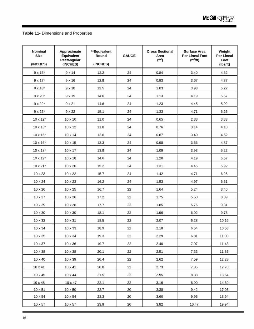
Table 11- Dimensions and Properties
NominalSize
(INCHES)
ApproximateEquivalent
Rectangular(INCHES)
**EquivalentRound
(INCHES)
GAUGECross Sectional
Area(ft2)
Surface AreaPer Lineal Foot
(ft2/ft)
WeightPer Lineal
Foot(lbs/ft)
16
9 x 15* 9 x 14 12.2 24 0.84 3.40 4.52
9 x 17* 9 x 16 12.9 24 0.93 3.67 4.87
9 x 18* 9 x 18 13.5 24 1.03 3.93 5.22
9 x 20* 9 x 19 14.0 24 1.13 4.19 5.57
9 x 22* 9 x 21 14.6 24 1.23 4.45 5.92
9 x 23* 9 x 22 15.1 24 1.33 4.71 6.26
10 x 12* 10 x 10 11.0 24 0.65 2.88 3.83
10 x 13* 10 x 12 11.8 24 0.76 3.14 4.18
10 x 15* 10 x 14 12.6 24 0.87 3.40 4.52
10 x 16* 10 x 15 13.3 24 0.98 3.66 4.87
10 x 18* 10 x 17 13.9 24 1.09 3.93 5.22
10 x 19* 10 x 18 14.6 24 1.20 4.19 5.57
10 x 21* 10 x 20 15.2 24 1.31 4.45 5.92
10 x 23 10 x 22 15.7 24 1.42 4.71 6.26
10 x 24 10 x 23 16.2 24 1.53 4.97 6.61
10 x 26 10 x 25 16.7 22 1.64 5.24 8.46
10 x 27 10 x 26 17.2 22 1.75 5.50 8.89
10 x 29 10 x 28 17.7 22 1.85 5.76 9.31
10 x 30 10 x 30 18.1 22 1.96 6.02 9.73
10 x 32 10 x 31 18.5 22 2.07 6.28 10.16
10 x 34 10 x 33 18.9 22 2.18 6.54 10.58
10 x 35 10 x 34 19.3 22 2.29 6.81 11.00
10 x 37 10 x 36 19.7 22 2.40 7.07 11.43
10 x 38 10 x 38 20.1 22 2.51 7.33 11.85
10 x 40 10 x 39 20.4 22 2.62 7.59 12.28
10 x 41 10 x 41 20.8 22 2.73 7.85 12.70
10 x 45 10 x 44 21.5 22 2.95 8.38 13.54
10 x 48 10 x 47 22.1 22 3.16 8.90 14.39
10 x 51 10 x 50 22.7 20 3.38 9.42 17.95
10 x 54 10 x 54 23.3 20 3.60 9.95 18.94
10 x 57 10 x 57 23.9 20 3.82 10.47 19.94

Table 11- Dimensions and Properties
NominalSize
(INCHES)
ApproximateEquivalent
Rectangular(INCHES)
**EquivalentRound
(INCHES)
GAUGECross Sectional
Area(ft2)
Surface AreaPer Lineal Foot
(ft2/ft)
WeightPer Lineal
Foot(lbs/ft)
17
10 x 60 10 x 60 24.4 20 4.04 11.00 20.94
10 x 63 10 x 63 25.0 20 4.25 11.52 21.94
10 x 67 10 x 66 25.5 20 4.47 12.04 22.93
10 x 70 10 x 69 26.0 20 4.69 12.57 23.93
10 x 73 10 x 73 26.4 18 4.91 13.09 32.45
10 x 76 10 x 76 26.9 18 5.13 13.61 33.75
10 x 79 10 x 79 27.3 18 5.35 14.14 35.05
11 x 14* 11 x 13 12.8 24 0.90 3.40 4.52
11 x 16* 11 x 14 13.6 24 1.02 3.66 4.87
11 x 17* 11 x 16 14.3 24 1.14 3.92 5.22
11 x 19* 11 x 18 15.0 24 1.26 4.19 5.57
11 x 20* 11 x 19 15.6 24 1.38 4.45 5.92
11 x 22* 11 x 21 16.3 24 1.50 4.71 6.26
11 x 24* 11 x 22 16.8 24 1.62 4.97 6.61
11 x 25* 11 x 24 17.4 22 1.74 5.23 8.46
12 x 14* 12 x 12 13.0 24 0.92 3.40 4.52
12 x 15* 12 x 14 13.8 24 1.05 3.67 4.87
12 x 17* 12 x 15 14.6 24 1.18 3.93 5.22
12 x 18* 12 x 17 15.4 24 1.31 4.19 5.57
12 x 20* 12 x 18 16.1 24 1.44 4.45 5.92
12 x 21* 12 x 20 16.7 24 1.57 4.71 6.26
12 x 23* 12 x 22 17.4 24 1.70 4.98 6.61
12 x 25 12 x 23 18.0 22 1.83 5.24 8.46
12 x 26 12 x 25 18.5 22 1.96 5.50 8.89
12 x 28 12 x 27 19.1 22 2.10 5.76 9.31
12 x 29 12 x 28 19.6 22 2.23 6.02 9.73
12 x 31 12 x 30 20.1 22 2.36 6.28 10.16
12 x 32 12 x 31 20.6 22 2.49 6.55 10.58
12 x 34 12 x 33 21.0 22 2.62 6.81 11.01
12 x 36 12 x 35 21.5 22 2.75 7.07 11.43
12 x 37 12 x 36 21.9 22 2.88 7.33 11.85
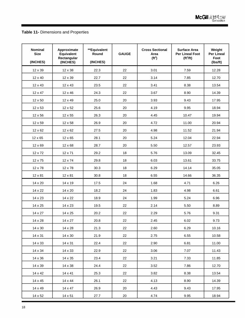
Table 11- Dimensions and Properties
NominalSize
(INCHES)
ApproximateEquivalent
Rectangular(INCHES)
**EquivalentRound
(INCHES)
GAUGECross Sectional
Area(ft2)
Surface AreaPer Lineal Foot
(ft2/ft)
WeightPer Lineal
Foot(lbs/ft)
18
12 x 39 12 x 38 22.3 22 3.01 7.59 12.28
12 x 40 12 x 39 22.7 22 3.14 7.85 12.70
12 x 43 12 x 43 23.5 22 3.41 8.38 13.54
12 x 47 12 x 46 24.3 22 3.67 8.90 14.39
12 x 50 12 x 49 25.0 20 3.93 9.43 17.95
12 x 53 12 x 52 25.6 20 4.19 9.95 18.94
12 x 56 12 x 55 26.3 20 4.45 10.47 19.94
12 x 59 12 x 58 26.9 20 4.72 11.00 20.94
12 x 62 12 x 62 27.5 20 4.98 11.52 21.94
12 x 65 12 x 65 28.1 20 5.24 12.04 22.94
12 x 69 12 x 68 28.7 20 5.50 12.57 23.93
12 x 72 12 x 71 29.2 18 5.76 13.09 32.45
12 x 75 12 x 74 29.8 18 6.03 13.61 33.75
12 x 78 12 x 78 30.3 18 6.29 14.14 35.05
12 x 81 12 x 81 30.8 18 6.55 14.66 36.35
14 x 20 14 x 19 17.5 24 1.68 4.71 6.26
14 x 22 14 x 20 18.2 24 1.83 4.98 6.61
14 x 23 14 x 22 18.9 24 1.99 5.24 6.96
14 x 25 14 x 23 19.5 22 2.14 5.50 8.89
14 x 27 14 x 25 20.2 22 2.29 5.76 9.31
14 x 28 14 x 27 20.8 22 2.45 6.02 9.73
14 x 30 14 x 28 21.3 22 2.60 6.29 10.16
14 x 31 14 x 30 21.9 22 2.75 6.55 10.58
14 x 33 14 x 31 22.4 22 2.90 6.81 11.00
14 x 34 14 x 33 22.9 22 3.06 7.07 11.43
14 x 36 14 x 35 23.4 22 3.21 7.33 11.85
14 x 39 14 x 38 24.4 22 3.52 7.86 12.70
14 x 42 14 x 41 25.3 22 3.82 8.38 13.54
14 x 45 14 x 44 26.1 22 4.13 8.90 14.39
14 x 49 14 x 47 26.9 20 4.43 9.43 17.95
14 x 52 14 x 51 27.7 20 4.74 9.95 18.94

Table 11- Dimensions and Properties
NominalSize
(INCHES)
ApproximateEquivalent
Rectangular(INCHES)
**EquivalentRound
(INCHES)
GAUGECross Sectional
Area(ft2)
Surface AreaPer Lineal Foot
(ft2/ft)
WeightPer Lineal
Foot(lbs/ft)
19
14 x 55 14 x 54 28.4 20 5.04 10.47 19.94
14 x 58 14 x 57 29.1 20 5.35 11.00 20.94
14 x 61 14 x 60 29.8 20 5.66 11.52 21.94
14 x 64 14 x 63 30.5 20 5.96 12.05 22.94
14 x 67 14 x 67 31.1 20 6.27 12.57 23.94
14 x 71 14 x 70 31.7 18 6.57 13.09 32.45
14 x 74 14 x 73 32.3 18 6.88 13.62 33.75
14 x 77 14 x 76 32.9 18 7.19 14.14 35.05
14 x 80 14 x 79 33.5 18 7.49 14.66 36.35
16 x 22 16 x 20 19.5 24 2.09 5.23 6.96
16 x 24 16 x 22 20.3 24 2.27 5.50 7.31
16 x 25 16 x 23 21.0 22 2.44 5.76 9.31
16 x 27 16 x 25 21.7 22 2.62 6.02 9.73
16 x 29 16 x 27 22.3 22 2.79 6.28 10.16
16 x 30 16 x 28 22.9 22 2.96 6.54 10.58
16 x 32 16 x 30 23.5 22 3.14 6.81 11.00
16 x 33 16 x 32 24.1 22 3.31 7.07 11.43
16 x 35 16 x 33 24.7 22 3.49 7.33 11.85
16 x 38 16 x 36 25.7 22 3.84 7.85 12.70
16 x 41 16 x 40 26.7 22 4.18 8.38 13.54
16 x 44 16 x 43 27.7 22 4.53 8.90 14.39
16 x 47 16 x 46 28.6 22 4.88 9.42 15.24
16 x 51 16 x 49 29.5 20 5.23 9.95 18.94
16 x 54 16 x 53 30.3 20 5.58 10.47 19.94
16 x 57 16 x 56 31.1 20 5.93 10.99 20.94
16 x 60 16 x 59 31.8 20 6.28 11.52 21.94
16 x 63 16 x 62 32.6 20 6.63 12.04 22.93
16 x 66 16 x 65 33.3 20 6.98 12.57 23.93
16 x 69 16 x 68 33.9 20 7.32 13.09 24.93
16 x 73 16 x 72 34.6 18 7.67 13.61 33.75
16 x 76 16 x 75 35.2 18 8.02 14.14 35.05

Table 11- Dimensions and Properties
NominalSize
(INCHES)
ApproximateEquivalent
Rectangular(INCHES)
**EquivalentRound
(INCHES)
GAUGECross Sectional
Area(ft2)
Surface AreaPer Lineal Foot
(ft2/ft)
WeightPer Lineal
Foot(lbs/ft)
20
16 x 79 16 x 78 35.9 18 8.37 14.66 36.35
18 x 23 18 x 20 20.7 24 2.36 5.50 7.31
18 x 24 18 x 22 21.6 24 2.55 5.76 7.66
18 x 26 18 x 24 22.3 22 2.75 6.02 9.73
18 x 27 18 x 25 23.1 22 2.94 6.28 10.16
18 x 29 18 x 27 23.8 22 3.14 6.54 10.58
18 x 31 18 x 28 24.5 22 3.34 6.81 11.00
18 x 32 18 x 30 25.1 22 3.53 7.07 11.43
18 x 34 18 x 32 25.7 22 3.73 7.33 11.85
18 x 35 18 x 33 26.3 22 3.92 7.59 12.27
18 x 37 18 x 35 26.9 22 4.12 7.85 12.70
18 x 40 18 x 38 28.0 22 4.51 8.38 13.54
18 x 43 18 x 41 29.1 22 4.91 8.90 14.39
18 x 46 18 x 45 30.1 22 5.30 9.42 15.24
18 x 49 18 x 48 31.1 20 5.69 9.95 18.94
18 x 53 18 x 51 31.4 20 5.83 10.14 19.31
18 x 56 18 x 54 32.8 20 6.48 10.99 20.94
18 x 59 18 x 57 33.7 20 6.87 11.52 21.94
18 x 62 18 x 61 34.5 20 7.26 12.04 22.93
18 x 65 18 x 64 35.2 20 7.65 12.56 23.93
18 x 68 18 x 67 36.0 20 8.05 13.09 24.93
18 x 71 18 x 70 36.7 18 8.44 13.61 33.75
18 x 75 18 x 73 37.4 18 8.83 14.14 35.05
18 x 78 18 x 76 38.1 18 9.22 14.66 36.35
18 x 81 18 x 80 38.8 18 9.62 15.18 37.65
20 x 26 20 x 24 23.6 22 3.05 6.28 10.16
20 x 28 20 x 25 24.4 22 3.27 6.54 10.58
20 x 29 20 x 27 25.2 22 3.49 6.81 11.00
20 x 31 20 x 28 25.9 22 3.71 7.07 11.43
20 x 33 20 x 30 26.6 22 3.93 7.33 11.85
20 x 36 20 x 33 27.9 22 4.36 7.85 12.70
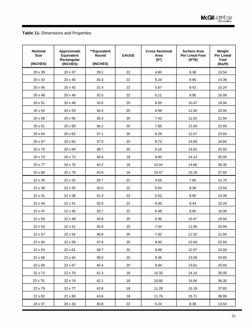
Table 11- Dimensions and Properties
NominalSize
(INCHES)
ApproximateEquivalent
Rectangular(INCHES)
**EquivalentRound
(INCHES)
GAUGECross Sectional
Area(ft2)
Surface AreaPer Lineal Foot
(ft2/ft)
WeightPer Lineal
Foot(lbs/ft)
21
20 x 39 20 x 37 29.1 22 4.80 8.38 13.54
20 x 42 20 x 40 30.3 22 5.24 8.90 14.39
20 x 45 20 x 43 31.4 22 5.67 9.42 15.24
20 x 48 20 x 46 32.5 22 6.11 9.95 16.08
20 x 51 20 x 49 33.5 20 6.55 10.47 19.94
20 x 55 20 x 53 34.4 20 6.98 11.00 20.94
20 x 58 20 x 56 35.3 20 7.42 11.52 21.94
20 x 61 20 x 59 36.2 20 7.85 12.04 22.93
20 x 64 20 x 62 37.1 20 8.29 12.57 23.93
20 x 67 20 x 65 37.9 20 8.73 13.09 24.93
20 x 70 20 x 69 38.7 20 9.16 13.61 25.93
20 x 73 20 x 72 39.4 18 9.60 14.14 35.05
20 x 77 20 x 75 40.2 18 10.04 14.66 36.35
20 x 80 20 x 78 40.9 18 10.47 15.18 37.65
22 x 35 22 x 32 28.7 22 4.56 7.86 12.70
22 x 38 22 x 35 30.0 22 5.04 8.38 13.54
22 x 41 22 x 38 31.3 22 5.52 8.90 14.39
22 x 44 22 x 41 32.5 22 6.00 9.43 15.24
22 x 47 22 x 45 33.7 22 6.48 9.95 16.08
22 x 50 22 x 48 34.8 20 6.96 10.47 19.94
22 x 53 22 x 51 35.8 20 7.44 11.00 20.94
22 x 57 22 x 54 36.8 20 7.92 11.52 21.94
22 x 60 22 x 58 37.8 20 8.40 12.04 22.93
22 x 63 22 x 61 38.7 20 8.88 12.57 23.93
22 x 66 22 x 64 39.6 20 9.36 13.09 24.93
22 x 69 22 x 67 40.4 20 9.84 13.61 25.93
22 x 72 22 x 70 41.3 18 10.32 14.14 35.05
22 x 75 22 x 74 42.1 18 10.80 14.66 36.35
22 x 79 22 x 77 42.8 18 11.28 15.19 37.65
22 x 82 22 x 80 43.6 18 11.76 15.71 38.95
24 x 37 24 x 33 30.8 22 5.24 8.38 13.54

Table 11- Dimensions and Properties
NominalSize
(INCHES)
ApproximateEquivalent
Rectangular(INCHES)
**EquivalentRound
(INCHES)
GAUGECross Sectional
Area(ft2)
Surface AreaPer Lineal Foot
(ft2/ft)
WeightPer Lineal
Foot(lbs/ft)
22
24 x 40 24 x 37 32.2 22 5.76 8.90 14.39
24 x 43 24 x 40 33.5 22 6.29 9.43 15.24
24 x 46 24 x 43 34.7 22 6.81 9.95 16.08
24 x 49 24 x 46 35.9 20 7.33 10.47 19.94
24 x 52 24 x 50 37.0 20 7.86 11.00 20.94
24 x 55 24 x 53 38.1 20 8.38 11.52 21.94
24 x 59 24 x 56 39.2 20 8.91 12.04 22.93
24 x 62 24 x 59 40.2 20 9.43 12.57 23.93
24 x 65 24 x 62 41.1 20 9.95 13.09 24.93
24 x 68 24 x 66 42.0 20 10.48 13.61 25.93
24 x 71 24 x 69 42.9 18 11.00 14.14 35.05
24 x 74 24 x 72 43.8 18 11.53 14.66 36.35
24 x 77 24 x 75 44.6 18 12.05 15.19 37.65
24 x 81 24 x 78 45.5 18 12.57 15.71 38.95
30 x 43 30 x 38 37.0 22 7.53 9.95 16.08
30 x 46 30 x 42 38.5 22 8.18 10.47 16.93
30 x 49 30 x 45 39.9 20 8.84 11.00 20.94
30 x 52 30 x 48 41.2 20 9.49 11.52 21.94
30 x 55 30 x 51 42.5 20 10.14 12.04 22.93
30 x 58 30 x 54 43.7 20 10.80 12.57 23.93
30 x 61 30 x 57 44.9 20 11.45 13.09 24.93
30 x 65 30 x 62 46.0 20 12.11 13.61 25.93
30 x 68 30 x 64 47.1 20 12.76 14.14 26.92
30 x 71 30 x 67 48.2 18 13.42 14.66 36.35
30 x 74 30 x 70 49.2 18 14.07 15.18 37.65
30 x 77 30 x 73 50.2 18 14.73 15.71 38.95
30 x 80 30 x 76 51.1 18 15.38 16.23 40.25
30 x 83 30 x 80 52.1 18 16.04 16.76 41.54
Equivalent rectangular size shown for a given flat oval size is the size of a rectangular duct that has the same friction loss per unitlength as the flat oval.Notes: ** = size listed is the diameter of round duct that has same friction loss per unit length.
* = 6-foot standard length.
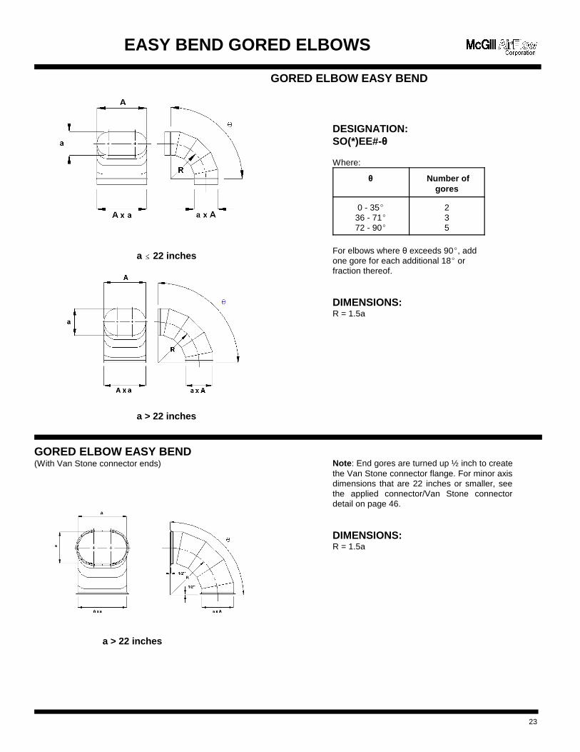
EASY BEND GORED ELBOWS
GORED ELBOW EASY BEND
a �� 22 inches
a > 22 inches
GORED ELBOW EASY BEND(With Van Stone connector ends)
a > 22 inches
23
Note: End gores are turned up ½ inch to createthe Van Stone connector flange. For minor axisdimensions that are 22 inches or smaller, seethe applied connector/Van Stone connectordetail on page 46.
DIMENSIONS:R = 1.5a
DESIGNATION:SO(*)EE#-�
Where:
� Number ofgores
0 - 35(36 - 71(72 - 90(
235
For elbows where � exceeds 90(, addone gore for each additional 18( orfraction thereof.
DIMENSIONS:R = 1.5a

Note: End gores are turned up and out ½ inch tocreate the Van Stone connector flange. Formajor axis dimensions that are 22 inches indiameter or smaller, see the appliedconnector/Van Stone connector detail on page46.
DIMENSIONS:R = 1.5A
Designation:SO(*)EH#-�
Where:
� Number ofgores
0 - 35(36 - 71(72 - 90(
235
For elbows where � exceeds 90(, addone gore for each additional 18( orfraction thereof.
DIMENSIONS:R = 1.5A
HARD BEND GORED ELBOWS
GORED ELBOW HARD BEND
A �� 22 inches
A > 22 inches
GORED ELBOW HARD BEND(With Van Stone connector ends)
A > 22 inches
24
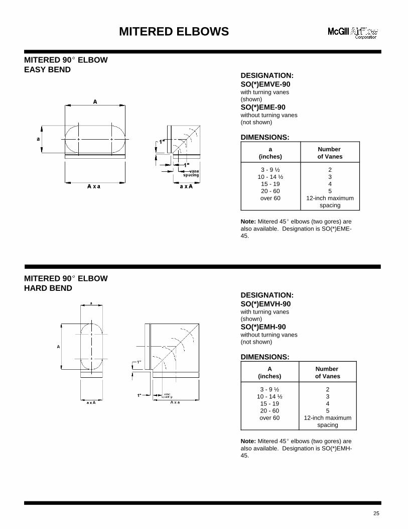
DESIGNATION:SO(*)EMVE-90with turning vanes(shown)SO(*)EME-90without turning vanes(not shown)
DIMENSIONS:
a(inches)
Number of Vanes
3 - 9 ½10 - 14 ½
15 - 1920 - 60over 60
2345
12-inch maximumspacing
Note: Mitered 45( elbows (two gores) arealso available. Designation is SO(*)EME-45.
DESIGNATION:SO(*)EMVH-90with turning vanes(shown)SO(*)EMH-90without turning vanes(not shown)
DIMENSIONS:
A(inches)
Number of Vanes
3 - 9 ½10 - 14 ½
15 - 1920 - 60over 60
2345
12-inch maximumspacing
Note: Mitered 45( elbows (two gores) arealso available. Designation is SO(*)EMH-45.
MITERED ELBOWS
MITERED 90(�
ELBOWEASY BEND
MITERED 90(�
ELBOWHARD BEND
25

EASY BEND HEEL-TAPPED ELBOWS
HEEL-TAPPED90(
�
ELBOWEASY BEND
Tap may be round ( C = c )
HEEL-TAPPED45(
�
ELBOWEASY BEND
Tap may be round ( C = c )
26
DESIGNATION:SO(*)ETE3-90
DIMENSIONS:R = 1.5aZ = 0.086a
Maximum c = aMaximum C = A
DESIGNATION:SO(*)ETE3-45
DIMENSIONS:R = 1.5aZ = 0.348a
Maximum c = 0.3aMaximum C = A

HARD BEND HEEL-TAPPED ELBOWS
HEEL-TAPPED90(
�
ELBOWHARD BEND
Tap may be round ( c = C)
HEEL-TAPPED45(
�
ELBOWHARD BEND
Tap may be round ( c = C)
27
DESIGNATION:SO(*)ETH3-90
DIMENSIONS:R = 1.5AZ = 0.086A
Maximum C = AMaximum c = a
DESIGNATION:SO(*)ETH3-45
DIMENSIONS:R = 1.5AZ = 0.348A
Maximum C = 0.3AMaximum c = a
DESIGNATION:SO(*)T
DIMENSIONS:V = C + 2Maximum C = AMaximum c = a
DESIGNATION:SO(*)TC
DIMENSIONS:V = C + 4Maximum C = A - 2Maximum c = a - 2
DESIGNATION:SO(*)TL
DIMENSIONS:V = C + H + 2J = c + 2 (for c � a - 2)J = c (for c > a - 2)Maximum C = AMaximum c = a
C(inches)
H(inches)
3 - 88 ½ - 14
14 ½ - 2627 orlarger
47
1013
TEES
STRAIGHT TEE
CONICAL TEE
LO-LOSS TEE
28

VC
sin2= +
θ
QA
2tan
C
2s in1= + +
θ θ
H =A
2s in+
C
2tan+ 2
θ θ
V =(C + 2)
s in+ 2
θ
QA
2tan
C 2
2s in1= +
++
θ
α
θ
HA
2sin
C 2
2 tan4= +
++
θ
α
θ
α
θ
=+
+
2
(C 2)
4 tan2
LATERALS
STRAIGHT LATERAL
Maximum C = A and c = a
CONICAL LATERAL
29
DESIGNATION:SO(*)L(-� if � g� 45(
�)
DIMENSIONS:
DESIGNATION:SO(*)LC(-� if � g� 45(
�)
(for � > 30()
DIMENSIONS:
Maximum C = A-3 for A�10 A-4 for A�42A-5 for A>42
Maximum c = A-2

CROSSES
STRAIGHT 90(�
CROSS
Either tap may be round ( c = C or d = D )
CONICAL 90(�
CROSS
Either tap may be round ( c = C or d = D )
LO-LOSS 90(�
CROSS
30
DESIGNATION:SO(*)TX(-3 if 3 g� 180(
�
)
DIMENSIONS:V = C + 2
Maximum C or D = AMaximum c or d = a
DESIGNATION:SO(*)TXC(-3 if 3 g� 180(
�
)
DIMENSIONS:V = C + 4
Maximum C or D = A - 2Maximum c or d = a - 2
DESIGNATION:SO(*)TXL(-3 if 3 g� 180(
�
)
DIMENSIONS:V = C + HC + 2
Note: To determine JC + JD dimension andmaximum C, D, c, or d, refer to the LO-LOSS teedrawing.
C or D(inches)
HC or HD
(inches)
3 - 89 - 14
15 - 2627 or larger
47
1013
DESIGNATION:SO(*)LX(-3 if 3 g� 180(
�,
-� if � g� 45(�)
VC
sin2= +
θ
QA
2tan
C
2s in1= + +
θ θ
HA
2sin
C
2 tan2C = + +
θ θ
HA
2s in
D
2tan2D = + +
θ θ
DESIGNATION:SO(*)EC (for duct)SO(*)ECF (for fittings)
CROSSES AND END CAP
LATERAL CROSS
Either tap may be round ( c = C or d = D )
Maximum C or D = AMaximum c or d = a
END CAP
31
DESIGNATION:SO(*)YE(-� if � g� 90(
�)
DIMENSIONS:
DESIGNATION:SO(*)YH(-� if � g� 90(
�)
DIMENSIONS:
HA
2tan ( / 2 )1= +
θ
mA
2tan ( / 4 )= θ
Ha
2tan ( / 2 )1= +
θ
ma
2tan( / 4 )= θ
Y-BRANCHES
Y-BRANCH, HARD BEND
Y-BRANCH, EASY BEND
32

DESIGNATION:SO(*)TBVHwith turning vanes(shown)
SO(*)TBHwithout turning vanes(not shown)
DIMENSIONS:V = A + 2
A(inches)
Numberof Vanes
7 - 910 - 60over 60
35
12-inchmaximumspacing
DESIGNATION:SO(*)TBVEwith turning vanes(shown)
SO(*)TBEwithout turning vanes(not shown)
DIMENSIONS:V = a + 2
a(inches)
Numberof Vanes
3 - 67 - 9
10 - 60over 60
135
12-inchmaximumspacing
BULLHEAD TEES
BULLHEAD TEE, HARD BEND
BULLHEAD TEE, EASY BEND
33

DESIGNATION:SO(*)PT
DIMENSIONS:Specify duct size to whichtap will be attached as a xA (if round body, specify Aonly).
Maximum C = AMaximum c = a
DESIGNATION:SO(*)PTS
DIMENSIONS:Specify duct size to whichtap will be attached as a xA (if round body, specify Aonly).
Maximum C = AMaximum c = a
DESIGNATION:SO(*)PTC
DIMENSIONS:Specify duct size to whichtap will be attached as a xA (if round body, specify Aonly).
Maximum C = A - 2Maximum c = a - 2
DESIGNATION:SO(*)PTCS
DIMENSIONS:Specify duct size to whichtap will be attached as a xA (if round body, specify Aonly).
Maximum C = A - 2Maximum c = a - 2
TAPS
CONTOURED FLANGED STRAIGHT TEE TAP
SADDLED STRAIGHT TEE TAP
CONTOURED FLANGED CONICAL TEE TAP
SADDLE CONICAL TEE TAP
34
TAPS
CONTOURED FLANGED LO-LOSS TEE TAP
SADDLE LO-LOSS TEE TAP
35
DESIGNATION:SO(*)PTL
DIMENSIONS:Specify duct size to whichtap will be attached as a xA (if round body, specify Aonly).
J = c + 2 (for c � a - 2)J = c (for c > a - 2)
Maximum C = AMaximum c = a
DESIGNATION:SO(*)PTLS
DIMENSIONS:Specify duct size to whichtap will be attached as a xA (if round body, specify aonly).
J = c + 2 (for c � a - 2)J = c (for c > a - 2)
Maximum C = AMaximum c = a
C(inches)
H(inches)
3 - 89 - 14
15 - 2627 or larger
47
1013
C(inches)
H(inches)
3 - 89 - 14
15 - 2627 or larger
47
1013

HA
2sin
C
2 tan2= + +
θ θ
DESIGNATION:SO(*)PL
DIMENSIONS:Specify duct size to which tap will beattached as a x A (if round body, specify Aonly).
Maximum C = AMaximum c = a
HA
2sin
C
2 tan2= + +
θ θ
DESIGNATION:SO(*)PLS(-� if � g� 45(
�
)
DIMENSIONS:Specify duct size to which tap will beattached as a x A (if round body, specify Aonly).
Maximum C = AMaximum c = a
TAPS
CONTOURED FLANGED LATERAL TAP
SADDLE LATERAL TAP
36
HA
2sin
C + 2
2 tan4= + +
θ
α
θ
α
θ
=+
+
2
(C 2)
4 tan2
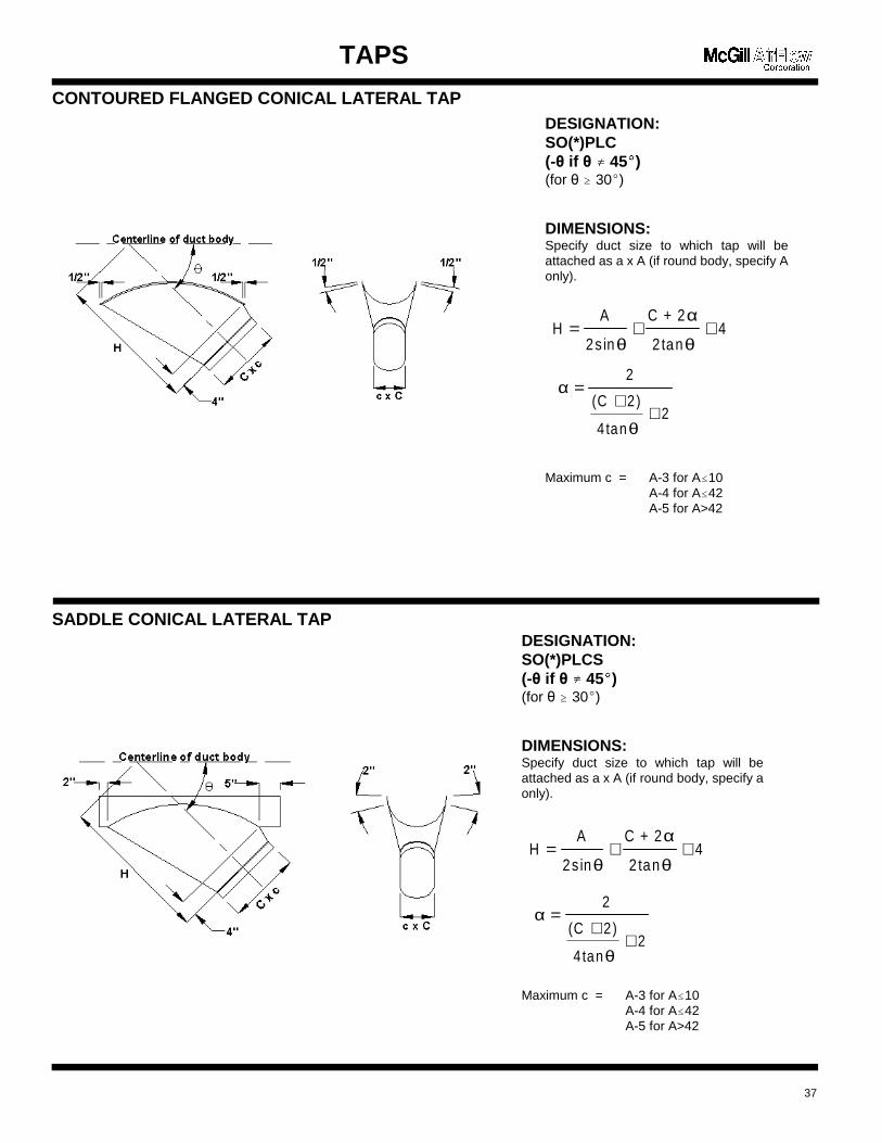
DESIGNATION:SO(*)PLC(-� if � g� 45(
�)
(for � � 30()
DIMENSIONS:Specify duct size to which tap will beattached as a x A (if round body, specify Aonly).
Maximum c = A-3 for A�10 A-4 for A�42A-5 for A>42
HA
2sin
C + 2
2 tan4= + +
θ
α
θ
α
θ
=+
+
2
(C 2)
4 tan2
DESIGNATION:SO(*)PLCS(-� if � g� 45(
�)
(for � � 30()
DIMENSIONS:Specify duct size to which tap will beattached as a x A (if round body, specify aonly).
Maximum c = A-3 for A�10 A-4 for A�42A-5 for A>42
TAPS
CONTOURED FLANGED CONICAL LATERAL TAP
SADDLE CONICAL LATERAL TAP
37

TAPS
RECTANGULAR TAP
RECTANGULAR LO-LOSS TAP
38
DESIGNATION:SO(*)PTA (Flange-in shown)
DIMENSIONS:Specify tap size ( W3 x H3 ) and duct size (A× a)that tap will be attached to and indicate enddetail, i.e., flange-in, flange-out, or raw. Providesketch of orientation if different than noted.
Default: TAPHT = 3 inches
DESIGNATION:SO(*)PTLA (Flange-in shown)
DIMENSIONS:Specify tap size ( W3 x H3 ) and duct size (A× a)that tap will be attached to and indicate enddetail, i.e., flange-in, flange-out, or raw. Providesketch of orientation if different than noted.
Default: TAPHT = 6 inchesSC = 2 inches� = 45 inches

DESIGNATION:SO(*)ZH
DIMENSIONS:V = 2A
Z = Must be specified
DESIGNATION:SO(*)ZE
DIMENSIONS:V = 2a
Z = Must be specified
DESIGNATION:SO(*)QR
DIMENSIONS:V = 12, 24, 36, or 48 inches
A = Major axis of rectangular sidea = Minor axis of rectangular side
Note: Z should not exceed 0.75A or �>60�. If larger, usefabricated elbows and a straight length of duct.
Note: Z should not exceed 0.75a or �>60�. If larger, usefabricated elbows and a straight length of duct.
OFFSETS and TRANSITIONS
OFFSET, HARD BEND
OFFSET, EASY BEND
SQUARE-TO-FLAT OVAL
39
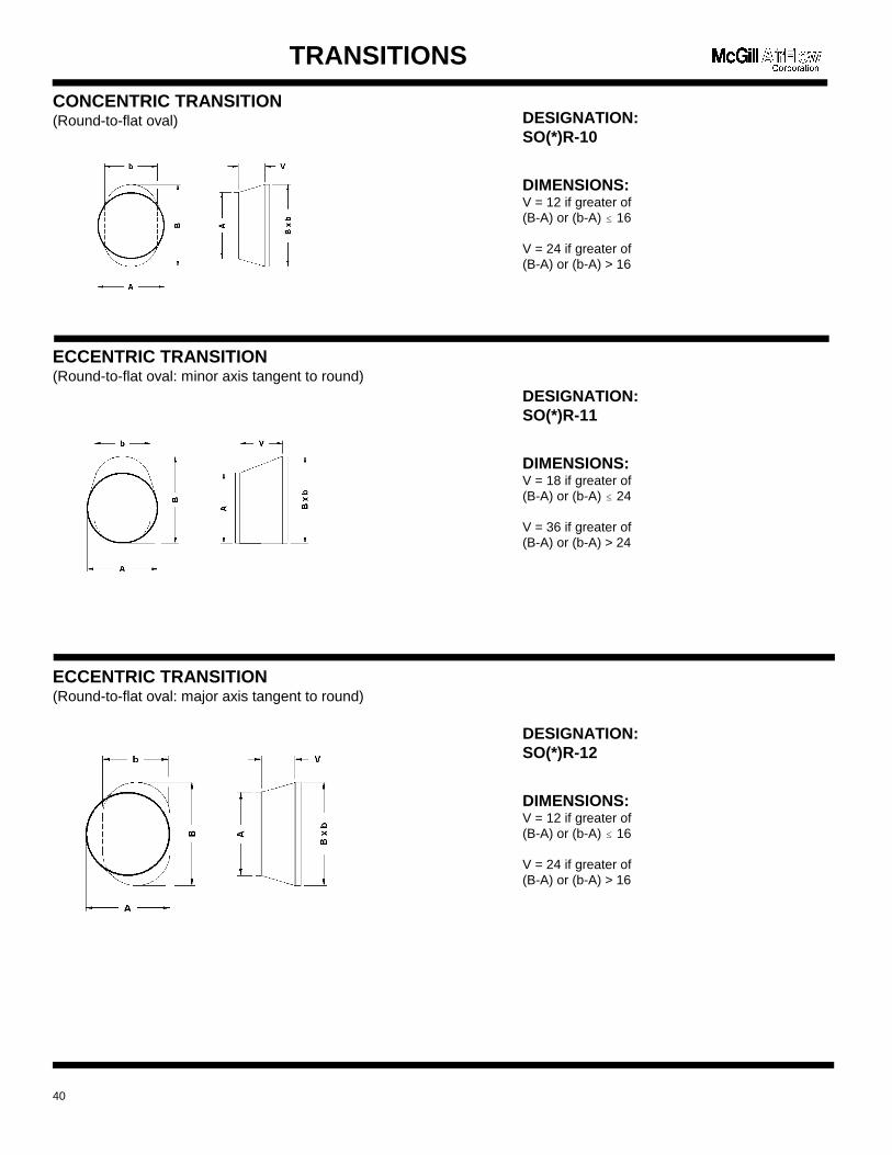
DESIGNATION:SO(*)R-10
DIMENSIONS:V = 12 if greater of (B-A) or (b-A) � 16
V = 24 if greater of (B-A) or (b-A) > 16
DESIGNATION:SO(*)R-11
DIMENSIONS:V = 18 if greater of (B-A) or (b-A) � 24
V = 36 if greater of (B-A) or (b-A) > 24
DESIGNATION:SO(*)R-12
DIMENSIONS:V = 12 if greater of (B-A) or (b-A) � 16
V = 24 if greater of (B-A) or (b-A) > 16
TRANSITIONS
CONCENTRIC TRANSITION(Round-to-flat oval)
ECCENTRIC TRANSITION(Round-to-flat oval: minor axis tangent to round)
ECCENTRIC TRANSITION(Round-to-flat oval: major axis tangent to round)
40

DESIGNATION:SO(*)R-131(ARR #1)SO(*)R-132(ARR #2)
DIMENSIONS:V = 18 if greater of (B-A) or (b-A) � 24
V = 36 if greater of (B-A) or (b-A) > 24
DESIGNATION:SO(*)R-30
DIMENSIONS:V = 12 if greater of (A-B) or (a-b) � 16
V = 24 if greater of (A-B) or (a-b) > 16
DESIGNATION:SO(*)R-31
DIMENSIONS:V = 18 if greater of (A-B) or (a-b) � 24
V = 36 if greater of (A-B) or (a-b) > 24
TRANSITIONS
ECCENTRIC TRANSITION(Round-to-flat oval: two adjacent sides tangent)
CONCENTRIC TRANSITION(Flat oval-to-flat oval: parallel axis)
ECCENTRIC TRANSITION(Flat oval-to-flat oval: parallel axis, minor axis sides tangent)
41

TRANSITIONS
ECCENTRIC TRANSITION(Flat oval-to-flat oval: parallel axis, major axis sides tangent)
ECCENTRIC TRANSITION(Flat oval-to-flat oval: parallel axis, two adjacent sides tangent)
CONCENTRIC TRANSITION(Flat oval-to-flat oval: rotated axis)
42
DESIGNATION:SO(*)R-32
DIMENSIONS:
V=12 if greater of (A-B) or (a-b) � 16
V = 24 if greater of (A-B) or (a-b) > 16
DESIGNATION:SO(*)R-331(ARR #1)SO(*)R-332(ARR #2)
DIMENSIONS:
V = 18 if greater of (A-B) or (a-b) � 24
V = 36 if greater of (A-B) or (a-b) > 24
DESIGNATION:SO(*)R-40
DIMENSIONS:
V = 12 if greater of (A-b) or (a-B) � 16
V = 24 if greater of (A-b) or (a-B) > 16

TRANSITIONS
ECCENTRIC TRANSITION(Flat oval-to-flat oval: rotated axis, tangent to air entering side minor axis)
ECCENTRIC TRANSITION(Flat oval-to-flat oval: rotated axis, tangent to air entering side major axis)
ECCENTRIC TRANSITION(Flat oval-to-flat oval: rotated axis, two adjacent sides tangent)
43
DESIGNATION:SO(*)R-41
DIMENSIONS:V=18 if greater of (A-b) or (a-B) � 24
V = 36 if greater of (A-b) or (a-B) > 24
DESIGNATION:SO(*)R-42
DIMENSIONS:V = 12 if greater of (A-b) or (a-B) � 16
V = 24 if greater of (A-b) or (a-B) > 16
DESIGNATION:SO(*)R-431(ARR #1)SO(*)R-432(ARR #2)
DIMENSIONS:V = 18 if greater of (A-b) or (a-B) � 24
V = 36 if greater of (A-b) or (a-B) > 24

DESIGNATION:SO(*)C
DIMENSIONS:
a(inches)
Bead(inches)
7 - 23over 23
1/45/8
DESIGNATION:SO(*)CF
COUPLINGS
DUCT-TO-DUCT COUPLING
FITTING-TO-FITTING COUPLING
44
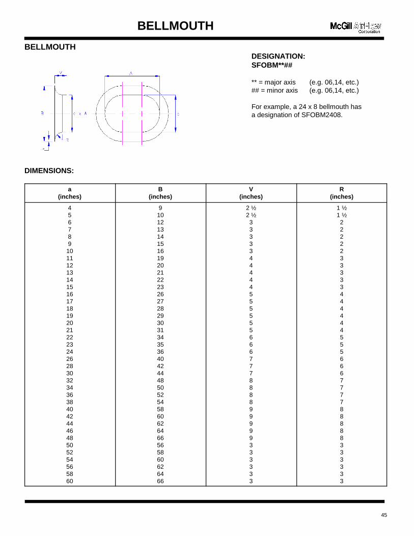
BELLMOUTH
BELLMOUTH
DIMENSIONS:
a(inches)
B(inches)
V(inches)
R(inches)
456789
101112131415161718192021222324262830323436384042444648505254565860
91012131415161920212223262728293031343536404244485052545860626466565860626466
2 ½2 ½3333344444555555666777888899999333333
1 ½1 ½2222233333444444555666777788888333333
45
DESIGNATION:SFOBM**##
** = major axis (e.g. 06,14, etc.)## = minor axis (e.g. 06,14, etc.)
For example, a 24 x 8 bellmouth hasa designation of SFOBM2408.
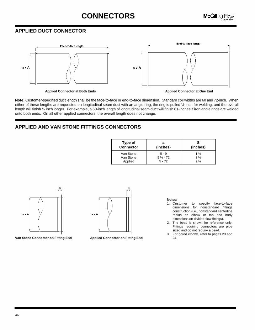
Type ofConnector
a(inches)
S(inches)
Van StoneVan Stone
Applied
5 - 99 ½ - 725 - 72
1 ½3 ½2 ¼
Notes:1. Customer to specify face-to-face
dimensions for nonstandard fittingsconstruction (i.e., nonstandard centerlineradius on elbow or tap and bodyextensions on divided-flow fittings).
2. The bead is shown for reference only.Fittings requiring connectors are pipesized and do not require a bead.
3. For gored elbows, refer to pages 23 and24.
CONNECTORS
APPLIED DUCT CONNECTOR
Applied Connector at Both Ends Applied Connector at One End
Note: Customer-specified duct length shall be the face-to-face or end-to-face dimension. Standard coil widths are 60 and 72-inch. Wheneither of these lengths are requested on longitudinal seam duct with an angle ring, the ring is pulled ½ inch for welding, and the overalllength will finish ½ inch longer. For example, a 60-inch length of longitudinal seam duct will finish 61-inches if iron angle rings are weldedonto both ends. On all other applied connectors, the overall length does not change.
APPLIED AND VAN STONE FITTINGS CONNECTORS
Van Stone Connector on Fitting End Applied Connector on Fitting End
46
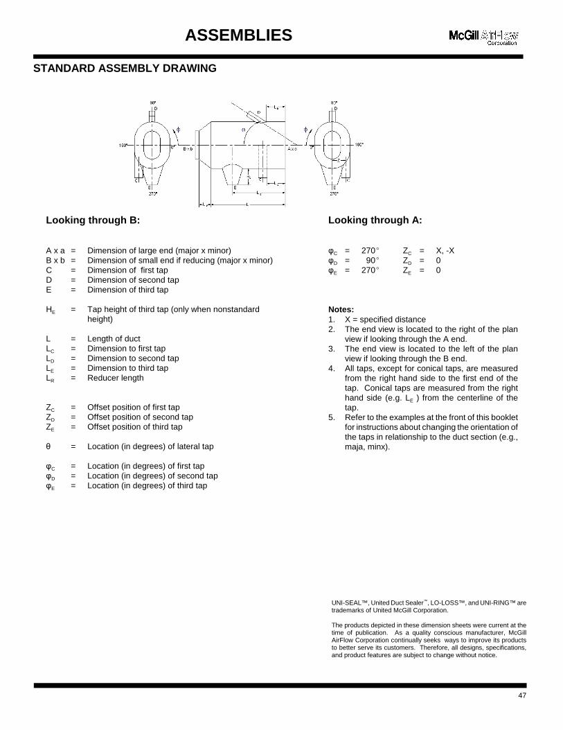
Looking through A:
3C = 270( ZC = X, -X3D = 90( ZD = 03E = 270( ZE = 0
Notes: 1. X = specified distance2. The end view is located to the right of the plan
view if looking through the A end.3. The end view is located to the left of the plan
view if looking through the B end.4. All taps, except for conical taps, are measured
from the right hand side to the first end of thetap. Conical taps are measured from the righthand side (e.g. LE ) from the centerline of thetap.
5. Refer to the examples at the front of this bookletfor instructions about changing the orientation ofthe taps in relationship to the duct section (e.g.,maja, minx).
Looking through B:
A x a = Dimension of large end (major x minor)B x b = Dimension of small end if reducing (major x minor)C = Dimension of first tapD = Dimension of second tapE = Dimension of third tap
HE = Tap height of third tap (only when nonstandardheight)
L = Length of ductLC = Dimension to first tapLD = Dimension to second tapLE = Dimension to third tapLR = Reducer length
ZC = Offset position of first tapZD = Offset position of second tapZE = Offset position of third tap
� = Location (in degrees) of lateral tap 3C = Location (in degrees) of first tap3D = Location (in degrees) of second tap3E = Location (in degrees) of third tap
ASSEMBLIES
STANDARD ASSEMBLY DRAWING
UNI-SEAL™, United Duct Sealer™, LO-LOSS™, and UNI-RING™ aretrademarks of United McGill Corporation.
The products depicted in these dimension sheets were current at thetime of publication. As a quality conscious manufacturer, McGillAirFlow Corporation continually seeks ways to improve its productsto better serve its customers. Therefore, all designs, specifications,and product features are subject to change without notice.
47

An enterprise of United McGill Corporation —Founded in 1951
Corporate HeadquartersOne Mission ParkGroveport, Ohio 43125-1149614/836-9981, Fax: 614/836-9843E-mail: [email protected] site: mcgillairflow.com