single-well sagd: overcoming permeable lean zones and...
TRANSCRIPT

Single-Well SAGD: Overcoming Permeable
Lean Zones and Barriers
Grant Hocking1, Travis Cavender2 & John Person2
1GeoSierra 2Halliburton
SPE148832
Canadian Unconventional Resources ConferenceCalgary, Alberta Canada 15-17 November, 2011

Thermal Enhanced Bitumen Recovery
Conventional SAGD– Reduced Steam Pressure
• Shallow depth, Caprock integrity, Outcrop proximity
– Geological Issues• Vertical Perm, Shale barriers, Lean zones
Conventional CSS– Geological Issues
• Bottom water, Caprock integrity, Top gas
Single-Well SAGD– Engineer around Geology
• High permeable propped vertical planes• Operate in SAGD mode
Conventional SAGD
Conventional CSS
Single-Well SAGD
Slide 2

Weakly Cemented Formations
Hydraulic Fracturing– Conventional
• Strong, Hard Rocks – Brittle Fracture– Frac & Pack
• Weak, Soft Sediments – Ductile Process
Weakly Cemented Formations– Minimal Cementation, Soft & Weak– Stress State
• Force Chains Fragile– Easily Destroyed– Minor Vibration or Shearing– Grain Contact Dissolution– Over-Pressurization
• Minimal Formation Stress Contrast– Stress Contrast can not be maintained
over geological time– Constitutive Behavior
• Ductile Frictional Behavior• Anelastic
Isotropic Compression Force Chains Shown
Minor Shear Strain Destroys Force Chains
Force Chains Destroyed
Slide 3

Early Field Trials of Azimuth Control
1990
1991 1991
Required Azimuth(String Line)
Required Azimuth(String Line)
Plane CoalescenceBeneath Surface
Plane Orientated AlongRequired Azimuth
1991 1991
Slide 4

Azimuth Control Initiation Devices
1991 1996
Prototype 1st Generation
1997
2nd Generation
Single Azimuth Tools
Slide 5

SENW
Cross-Section
Plan View
Azimuth Control Iron Propped Planes
Deep PRB
Upper PRB
Pilot PRB
FormerPump & TreatFacility
Location IP-10 (F52-F53)
0
2
4
6
8
10
12
14
16
18
20
16.0 16.5 17.0 17.5 18.0 18.5 19.0 19.5 20.0 20.5 21.0Corrected Horizontal Distance (ft)
Res
istiv
ity (O
hm) Inclined Wall Thickness interpreted
to be approximately 4.8-inches
Slide 6

Multi-Azimuth Vertical Planes
Each individual Plane Initiated & Propagated by Dedicated Tubing
Diametrically Opposite Cavities are Dilated to Initiate Azimuth Controlled Vertical Planes
Slide 7

Milk River Tight Gas Field Trials
100km
AlbertaSaskatchewan
Four (4) propped wings
Shoreline Anisotropy
4-1/2” J55 Casing
Slide 8

Single-Well SAGD System
Sump
Top Pay
Bottom Pay
Operated in SAGD Mode- no startup - shallow or deep
Injector
Producer
Slide 9

Single-Well SAGD Completion
Casing Liner Composite
9-5/8” 7”
Epoxy Ceramic
Legend
Cementing Shoe
X-Drain Casing
Orientating Mule Shoe
Slotted Liner
CompletionBlanket Gas
Steam4-1/2” VIT Produced Liquids
2-7/8” or 3-1/2”
Slotted Liner
Slide 10

Thermal Simulation Model Idealization
Modeled Region
Steam InjectionProduced Oil
Lines of Symmetry
1/2 Well SpacingWing Length
TRS-Thermal Simulator Athabasca Bitumen Sp=1,750kPa and 1,200kPa
Slide 11

Athabasca Bitumen Sp=1,750kPa
Slide 12

Single-Well SAGD in Channel Sand
Athabasca Bitumen Sp=1,750kPa Time (days)
Oil
Pro
duct
ion
Rat
e(b
bls/
day)
Cum
mul
ativ
eO
il(M
Mbb
ls)
Cum
ulat
ive
SO
R
0 500 1000 1500 2000 2500 3000 35000
100
200
300
400
500
600
0
0.2
0.4
0.6
0.8
1
1.2
0
1
2
3
4
5
Oil RateCum OilCSOR
50%
Single-Well SAGD
Slide 113

4x Single-Well vs Conventional SAGD
Athabasca Bitumen Sp=1,750kPa Time (days)
Oil
Pro
duct
ion
Rat
e(M
bbls
/day
)
Cum
mul
ativ
eO
il(M
Mbb
ls)
Cum
ulat
ive
SO
R
0 500 1000 1500 2000 2500 3000 35000
0.5
1
1.5
2
2.5
3
0
1
2
3
4
0
1
2
3
4
5
50% 50%
S-W SAGDConv SAGD
Single-Well SAGD Conventional SAGD
Faster Recovery
Slide 14
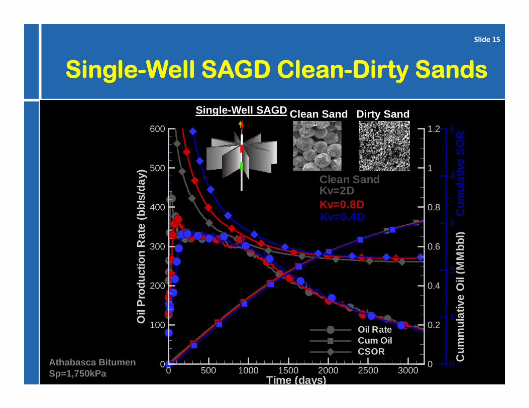
Single-Well SAGD Clean-Dirty Sands
Time (days)
Oil
Pro
duct
ion
Rat
e(b
bls/
day)
Cum
mul
ativ
eO
il(M
Mbb
l)C
umul
ativ
eS
OR
0 500 1000 1500 2000 2500 30000
100
200
300
400
500
600
0
0.2
0.4
0.6
0.8
1
1.2
0
1
2
3
4
5
Oil RateCum OilCSOR
Clean SandKv=2DKv=0.8DKv=0.4D
Single-Well SAGD Clean Sand Dirty Sand
Athabasca Bitumen Sp=1,750kPa
Slide 15
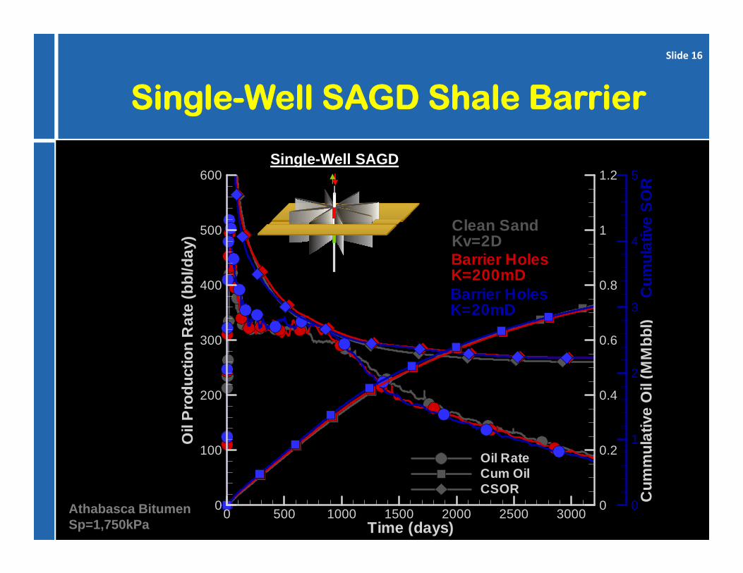
Single-Well SAGD Shale Barrier
Time (days)
Oil
Pro
duct
ion
Rat
e(b
bl/d
ay)
Cum
mul
ativ
eO
il(M
Mbb
l)C
umul
ativ
eS
OR
0 500 1000 1500 2000 2500 30000
100
200
300
400
500
600
0
0.2
0.4
0.6
0.8
1
1.2
0
1
2
3
4
5
Oil RateCum OilCSOR
Clean SandKv=2DBarrier HolesK=200mDBarrier HolesK=20mD
Single-Well SAGD
Athabasca Bitumen Sp=1,750kPa
Slide 16

Permeable Lean Zone
Water SaturationTemperature 0.1day
Temperature 1day
Temperature 6daysTemperature 30days
Temperature 90days
T °CPermeable lean zone
Athabasca Bitumen Sp=1,200kPa
Slide 17

T °C
Athabasca Bitumen Sp=1,200kPa
Slide 18

Conclusions• Process not depth limited
• Reservoir simulations indicate performance almost invariant of geology
• As built issues– Skin between coalesced vertical planes– Permeability of planes needs to be high
• In placed permeability• Maintain permeability over time
– Steaming trials required to quantify issues
AcknowledgementsDale Walters, Taurus Reservoir Solutions for reservoir simulationsSuncor, for access & field support of Milk River trials
Slide 19