sinumerik operate - turning - siemens · 12.2.2 detection of residual material when milling ... 13...
TRANSCRIPT
� SINUMERIK Operate - � Turning
_________________________________________________________________________________________________________________________________________________________________________________________________________________________________________________________________________________________________________________________________________________________________________
SINUMERIK 840D sl
SINUMERIK Operate - Turning
Control system overview for machine tools' sales people
09/2012
Preface
Introduction 1
System overview 2
CNC operation in manual mode (JOG)
3
Tool management 4
User memory 5
Data transfer 6
Graphical support functions 7
CNC operation in automatic mode (AUTO)
8CNC performance capability and optimization functions
9
CNC programming methods 10
Simulation 11
CNC technology cycles 12
Complete machining 13
Multi-channel machining 14
PC software 15
Integrated safety functions 16
Option list for the SINUMERIK package
17
Summary of unique features 18
Siemens AG Industry Sector Postfach 48 48 90026 NÜRNBERG GERMANY
Ⓟ 09/2012 Technical data subject to change
Copyright © Siemens AG 2012. All rights reserved
Legal information Warning notice system
This manual contains notices you have to observe in order to ensure your personal safety, as well as to prevent damage to property. The notices referring to your personal safety are highlighted in the manual by a safety alert symbol, notices referring only to property damage have no safety alert symbol. These notices shown below are graded according to the degree of danger.
DANGER indicates that death or severe personal injury will result if proper precautions are not taken.
WARNING indicates that death or severe personal injury may result if proper precautions are not taken.
CAUTION indicates that minor personal injury can result if proper precautions are not taken.
NOTICE indicates that property damage can result if proper precautions are not taken.
If more than one degree of danger is present, the warning notice representing the highest degree of danger will be used. A notice warning of injury to persons with a safety alert symbol may also include a warning relating to property damage.
Qualified Personnel The product/system described in this documentation may be operated only by personnel qualified for the specific task in accordance with the relevant documentation, in particular its warning notices and safety instructions. Qualified personnel are those who, based on their training and experience, are capable of identifying risks and avoiding potential hazards when working with these products/systems.
Proper use of Siemens products Note the following:
WARNING Siemens products may only be used for the applications described in the catalog and in the relevant technical documentation. If products and components from other manufacturers are used, these must be recommended or approved by Siemens. Proper transport, storage, installation, assembly, commissioning, operation and maintenance are required to ensure that the products operate safely and without any problems. The permissible ambient conditions must be complied with. The information in the relevant documentation must be observed.
Trademarks All names identified by ® are registered trademarks of Siemens AG. The remaining trademarks in this publication may be trademarks whose use by third parties for their own purposes could violate the rights of the owner.
Disclaimer of Liability We have reviewed the contents of this publication to ensure consistency with the hardware and software described. Since variance cannot be precluded entirely, we cannot guarantee full consistency. However, the information in this publication is reviewed regularly and any necessary corrections are included in subsequent editions.
SINUMERIK Operate - Turning, SINUMERIK 840D sl Control system overview for machine tools' sales people, 09/2012 3
Preface
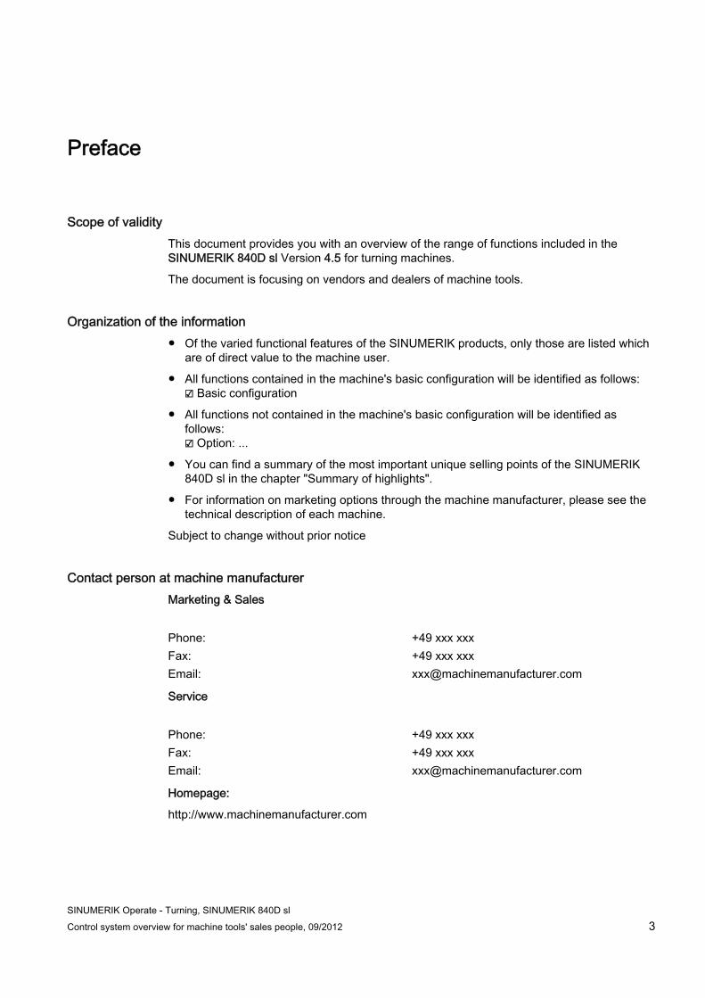
Scope of validity This document provides you with an overview of the range of functions included in the SINUMERIK 840D sl Version 4.5 for turning machines.
The document is focusing on vendors and dealers of machine tools.
Organization of the information ● Of the varied functional features of the SINUMERIK products, only those are listed which
are of direct value to the machine user.
● All functions contained in the machine's basic configuration will be identified as follows: ☑ Basic configuration
● All functions not contained in the machine's basic configuration will be identified as follows: ☑ Option: ...
● You can find a summary of the most important unique selling points of the SINUMERIK 840D sl in the chapter "Summary of highlights".
● For information on marketing options through the machine manufacturer, please see the technical description of each machine.
Subject to change without prior notice
Contact person at machine manufacturer Marketing & Sales
Phone: +49 xxx xxx Fax: +49 xxx xxx Email: [email protected]
Service
Phone: +49 xxx xxx Fax: +49 xxx xxx Email: [email protected]
Homepage:
http://www.machinemanufacturer.com
Preface
SINUMERIK Operate - Turning, SINUMERIK 840D sl 4 Control system overview for machine tools' sales people, 09/2012
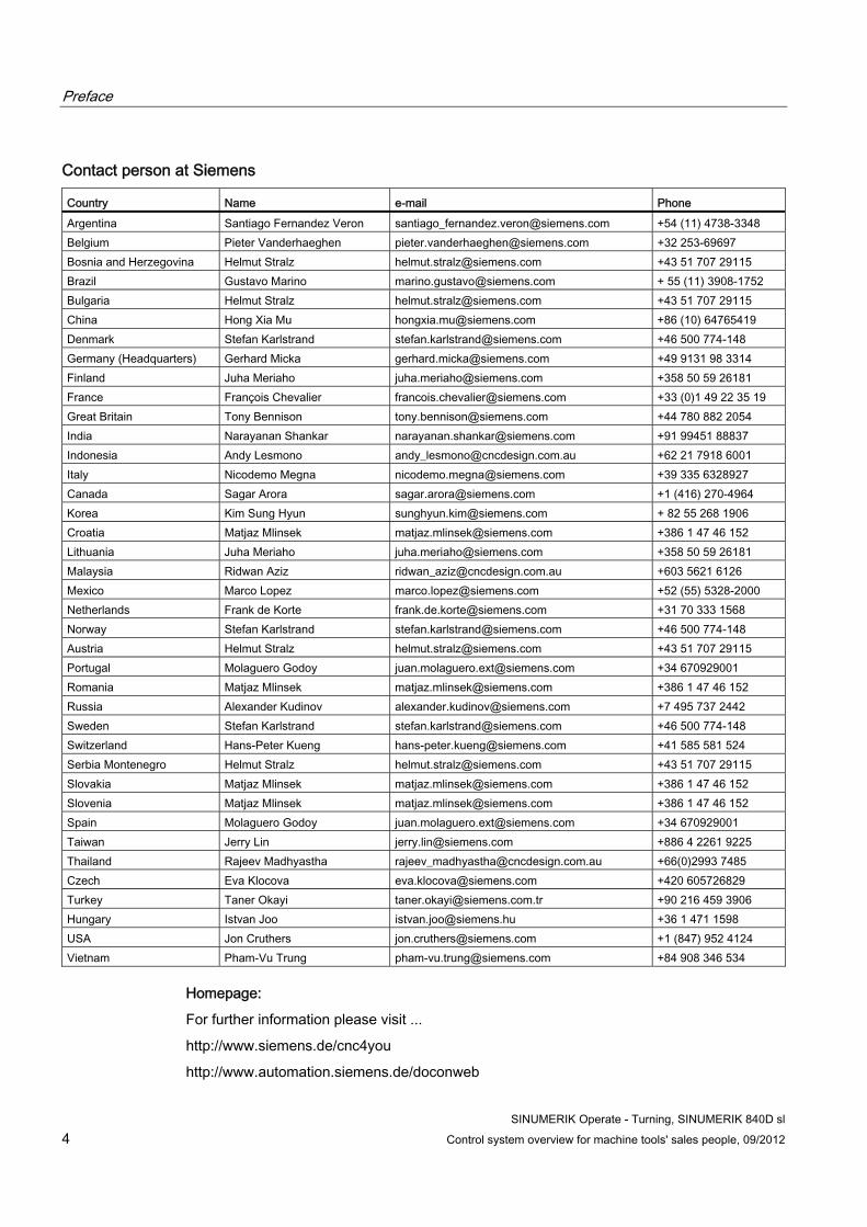
Contact person at Siemens
Country Name e-mail Phone Argentina Santiago Fernandez Veron [email protected] +54 (11) 4738-3348 Belgium Pieter Vanderhaeghen [email protected] +32 253-69697 Bosnia and Herzegovina Helmut Stralz [email protected] +43 51 707 29115 Brazil Gustavo Marino [email protected] + 55 (11) 3908-1752 Bulgaria Helmut Stralz [email protected] +43 51 707 29115 China Hong Xia Mu [email protected] +86 (10) 64765419 Denmark Stefan Karlstrand [email protected] +46 500 774-148 Germany (Headquarters) Gerhard Micka [email protected] +49 9131 98 3314 Finland Juha Meriaho [email protected] +358 50 59 26181 France François Chevalier [email protected] +33 (0)1 49 22 35 19 Great Britain Tony Bennison [email protected] +44 780 882 2054 India Narayanan Shankar [email protected] +91 99451 88837 Indonesia Andy Lesmono [email protected] +62 21 7918 6001 Italy Nicodemo Megna [email protected] +39 335 6328927 Canada Sagar Arora [email protected] +1 (416) 270-4964 Korea Kim Sung Hyun [email protected] + 82 55 268 1906 Croatia Matjaz Mlinsek [email protected] +386 1 47 46 152 Lithuania Juha Meriaho [email protected] +358 50 59 26181 Malaysia Ridwan Aziz [email protected] +603 5621 6126 Mexico Marco Lopez [email protected] +52 (55) 5328-2000 Netherlands Frank de Korte [email protected] +31 70 333 1568 Norway Stefan Karlstrand [email protected] +46 500 774-148 Austria Helmut Stralz [email protected] +43 51 707 29115 Portugal Molaguero Godoy [email protected] +34 670929001 Romania Matjaz Mlinsek [email protected] +386 1 47 46 152 Russia Alexander Kudinov [email protected] +7 495 737 2442 Sweden Stefan Karlstrand [email protected] +46 500 774-148 Switzerland Hans-Peter Kueng [email protected] +41 585 581 524 Serbia Montenegro Helmut Stralz [email protected] +43 51 707 29115 Slovakia Matjaz Mlinsek [email protected] +386 1 47 46 152 Slovenia Matjaz Mlinsek [email protected] +386 1 47 46 152 Spain Molaguero Godoy [email protected] +34 670929001 Taiwan Jerry Lin [email protected] +886 4 2261 9225 Thailand Rajeev Madhyastha [email protected] +66(0)2993 7485 Czech Eva Klocova [email protected] +420 605726829 Turkey Taner Okayi [email protected] +90 216 459 3906 Hungary Istvan Joo [email protected] +36 1 471 1598 USA Jon Cruthers [email protected] +1 (847) 952 4124 Vietnam Pham-Vu Trung [email protected] +84 908 346 534
Homepage:
For further information please visit ...
http://www.siemens.de/cnc4you
http://www.automation.siemens.de/doconweb
SINUMERIK Operate - Turning, SINUMERIK 840D sl Control system overview for machine tools' sales people, 09/2012 5
Table of contents
Preface ...................................................................................................................................................... 3
1 Introduction................................................................................................................................................ 9
1.1 Application......................................................................................................................................9
1.2 Machine spectrum........................................................................................................................10
2 System overview...................................................................................................................................... 11
2.1 SINUMERIK 840D sl....................................................................................................................11
2.2 Operator panel fronts ...................................................................................................................12
2.3 Operator panel equipment ...........................................................................................................16
3 CNC operation in manual mode (JOG) .................................................................................................... 19
3.1 TSM universal cycle.....................................................................................................................19
3.2 Positioning cycle ..........................................................................................................................20
3.3 Stock removal cycle .....................................................................................................................21
3.4 Measure tool ................................................................................................................................22
3.5 Measure workpiece......................................................................................................................23
3.6 Work offsets .................................................................................................................................24
4 Tool management.................................................................................................................................... 25
4.1 Tool table .....................................................................................................................................25
4.2 Monitoring of tool life and workpiece count..................................................................................26
4.3 Replacement tools .......................................................................................................................27
4.4 Setup data....................................................................................................................................27
5 User memory ........................................................................................................................................... 29
5.1 Buffered CNC work memory ........................................................................................................29
5.2 CompactFlash card......................................................................................................................29
5.3 Hard disk ......................................................................................................................................30
5.4 Card reader ..................................................................................................................................30
5.5 USB Hub 4 ...................................................................................................................................31
6 Data transfer............................................................................................................................................ 33
6.1 Program manager ........................................................................................................................33
6.2 Data transfer using the USB memory stick..................................................................................34
6.3 RCS Commander.........................................................................................................................34
6.4 Ethernet networking .....................................................................................................................35
Table of contents
SINUMERIK Operate - Turning, SINUMERIK 840D sl 6 Control system overview for machine tools' sales people, 09/2012
7 Graphical support functions ..................................................................................................................... 37
7.1 Animated Elements ..................................................................................................................... 37
7.2 Onboard documentation.............................................................................................................. 38
8 CNC operation in automatic mode (AUTO).............................................................................................. 39
8.1 Block search................................................................................................................................ 39
8.2 Basic block display...................................................................................................................... 40
8.3 Program control........................................................................................................................... 41
8.4 Simultaneous recording .............................................................................................................. 42
9 CNC performance capability and optimization functions .......................................................................... 43
9.1 80bit NANOFP accuracy............................................................................................................... 43
9.2 Jerk limitation .............................................................................................................................. 44
9.3 Dynamic feedforward control ...................................................................................................... 45
9.4 Look Ahead ................................................................................................................................. 46
10 CNC programming methods .................................................................................................................... 47
10.1 Overview of programming methods ............................................................................................ 47
10.2 programGUIDE and SINUMERIK CNC programming ................................................................ 48 10.2.1 Introduction ................................................................................................................................. 48 10.2.2 Program editor ............................................................................................................................ 48 10.2.3 Languages .................................................................................................................................. 49 10.2.4 programGUIDE input support...................................................................................................... 50
10.3 ShopTurn..................................................................................................................................... 51 10.3.1 Introduction ................................................................................................................................. 51 10.3.2 Sequence editor .......................................................................................................................... 51 10.3.3 Interlinking of sequences ............................................................................................................ 52 10.3.4 Broken-line graphics ................................................................................................................... 53
10.4 Online ISO dialect interpreter...................................................................................................... 54
11 Simulation................................................................................................................................................ 55
11.1 2D simulation .............................................................................................................................. 55
11.2 3D simulation .............................................................................................................................. 56
12 CNC technology cycles............................................................................................................................ 57
12.1 Highlights of machining cycles.................................................................................................... 58 12.1.1 Stock removal along contour with blank contour ........................................................................ 58 12.1.2 Engraving cycle........................................................................................................................... 59 12.1.3 Counterspindle cycle................................................................................................................... 60
12.2 Residual material detection......................................................................................................... 61 12.2.1 Residual material detection during turning.................................................................................. 61 12.2.2 Detection of residual material when milling................................................................................. 62
12.3 In-process measuring for workpieces and tools.......................................................................... 63
Table of contents
SINUMERIK Operate - Turning, SINUMERIK 840D sl Control system overview for machine tools' sales people, 09/2012 7
13 Complete machining ................................................................................................................................ 65
13.1 End face machining (TRANSMIT)................................................................................................65
13.2 Peripheral surface machining (TRACYL).....................................................................................66
14 Multi-channel machining .......................................................................................................................... 67
14.1 Overview ......................................................................................................................................67
14.2 programSYNC job list ..................................................................................................................68
14.3 Double editor................................................................................................................................69
14.4 Simulation ....................................................................................................................................70
15 PC software ............................................................................................................................................. 71
15.1 CAD reader for PC.......................................................................................................................71
15.2 SinuTrain......................................................................................................................................72
15.3 Computer-based training .............................................................................................................72
16 Integrated safety functions....................................................................................................................... 73
17 Option list for the SINUMERIK package .................................................................................................. 75
18 Summary of unique features.................................................................................................................... 77
Index........................................................................................................................................................ 79
Table of contents
SINUMERIK Operate - Turning, SINUMERIK 840D sl 8 Control system overview for machine tools' sales people, 09/2012
SINUMERIK Operate - Turning, SINUMERIK 840D sl Control system overview for machine tools' sales people, 09/2012 9
Introduction 11.1 Application
With the SINUMERIK 840D sl and the operating software SINUMERIK Operate you have a tailored solution for all CNC turning machines used worldwide.
When operating the machine tool, you are supported by graphic help screens and Animated Elements.
The functions in the manual mode enable a quick, practical machine set-up. More specifically, this consists of calculating the workpiece position in the machine, as well as the maintenance and dimensioning of the tools in use.
You have three different options when programming:
● programmGUIDE and SINUMERIK CNC programming, with a wide selection of technology cycles for medium series and large series production.
● ShopTurn, with automatic cascading (linking) of associated machining steps for small series production.
● ISO dialect and SINUMERIK CNC programming language with IOSO dialect interpreter.
The SINUMERIK 840D sl with the operating software SINUMERIK Operate offers a control configuration that covers all of the required application areas without subsequent commissioning and training costs:
● Easy-to-use interface for all machine functions
● DIN/ISO programming on the machine or offline via the CAD/CAM system
● Graphic programming
● Complete machining
● In-process measuring for workpieces and tools
Introduction 1.2 Machine spectrum
SINUMERIK Operate - Turning, SINUMERIK 840D sl 10 Control system overview for machine tools' sales people, 09/2012
1.2 Machine spectrum The SINUMERIK 840D sl with the operating software SINUMERIK Operate is perfectly suited for the following types of machines:
1. Single-slide turning machines with X and Z axes
– Turning operations
– Centric drilling on the end face
2. Like 1.) with rotating tools (C axis mode)
– Any drilling or milling on the end face and outer surface
3. Like 1.) or 2.) with additional Y axis
– Any drilling or milling on the end face and outer surface
4. Like 1.), 2.) or 3.) with additional counterspindle for front and rear machining
SINUMERIK Operate - Turning, SINUMERIK 840D sl Control system overview for machine tools' sales people, 09/2012 11
System overview 22.1 SINUMERIK 840D sl
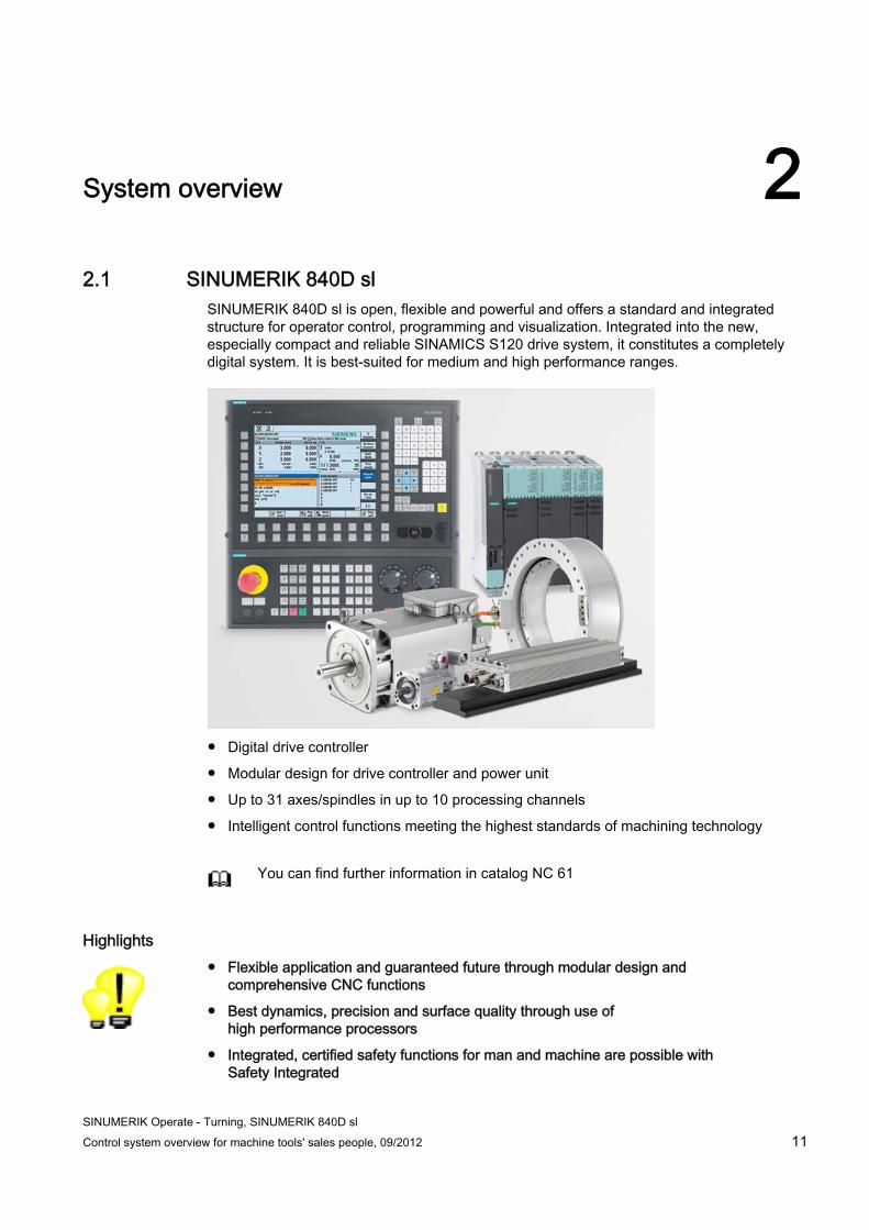
SINUMERIK 840D sl is open, flexible and powerful and offers a standard and integrated structure for operator control, programming and visualization. Integrated into the new, especially compact and reliable SINAMICS S120 drive system, it constitutes a completely digital system. It is best-suited for medium and high performance ranges.
● Digital drive controller
● Modular design for drive controller and power unit
● Up to 31 axes/spindles in up to 10 processing channels
● Intelligent control functions meeting the highest standards of machining technology
You can find further information in catalog NC 61
Highlights ● Flexible application and guaranteed future through modular design and
comprehensive CNC functions
● Best dynamics, precision and surface quality through use of high performance processors
● Integrated, certified safety functions for man and machine are possible with Safety Integrated
System overview 2.2 Operator panel fronts
SINUMERIK Operate - Turning, SINUMERIK 840D sl 12 Control system overview for machine tools' sales people, 09/2012
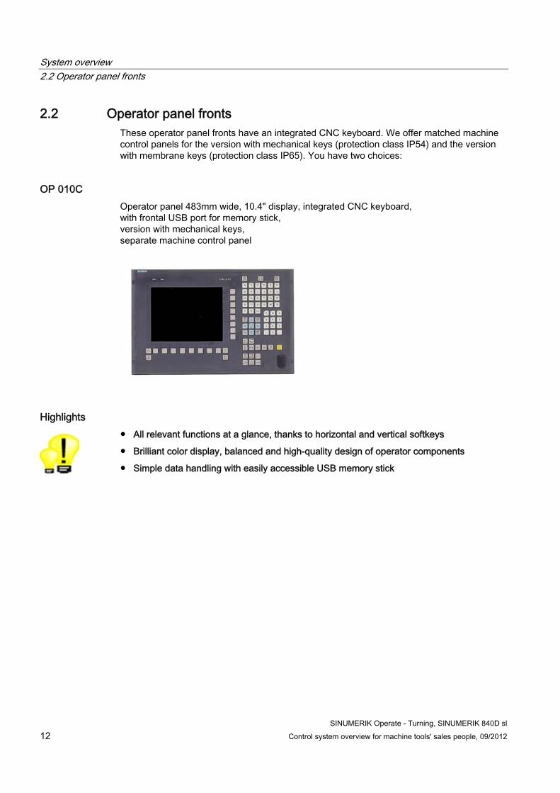
2.2 Operator panel fronts These operator panel fronts have an integrated CNC keyboard. We offer matched machine control panels for the version with mechanical keys (protection class IP54) and the version with membrane keys (protection class IP65). You have two choices:
OP 010C Operator panel 483mm wide, 10.4" display, integrated CNC keyboard, with frontal USB port for memory stick, version with mechanical keys, separate machine control panel
Highlights ● All relevant functions at a glance, thanks to horizontal and vertical softkeys
● Brilliant color display, balanced and high-quality design of operator components
● Simple data handling with easily accessible USB memory stick
System overview 2.2 Operator panel fronts
SINUMERIK Operate - Turning, SINUMERIK 840D sl Control system overview for machine tools' sales people, 09/2012 13
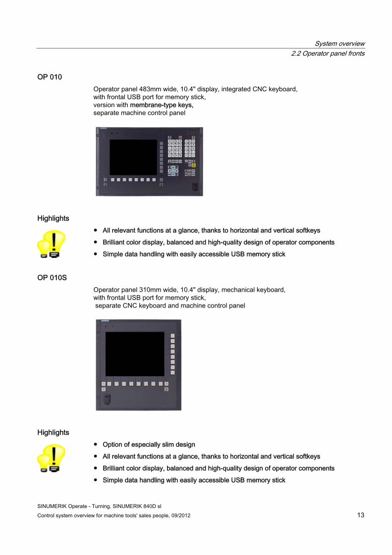
OP 010 Operator panel 483mm wide, 10.4" display, integrated CNC keyboard, with frontal USB port for memory stick, version with membrane-type keys, separate machine control panel
Highlights ● All relevant functions at a glance, thanks to horizontal and vertical softkeys
● Brilliant color display, balanced and high-quality design of operator components
● Simple data handling with easily accessible USB memory stick
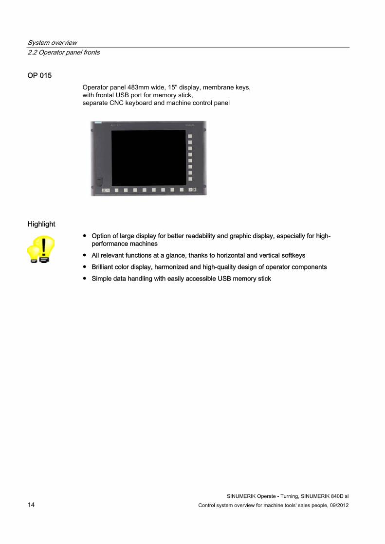
OP 010S Operator panel 310mm wide, 10.4" display, mechanical keyboard, with frontal USB port for memory stick, separate CNC keyboard and machine control panel
Highlights ● Option of especially slim design
● All relevant functions at a glance, thanks to horizontal and vertical softkeys
● Brilliant color display, balanced and high-quality design of operator components
● Simple data handling with easily accessible USB memory stick
System overview 2.2 Operator panel fronts
SINUMERIK Operate - Turning, SINUMERIK 840D sl 14 Control system overview for machine tools' sales people, 09/2012
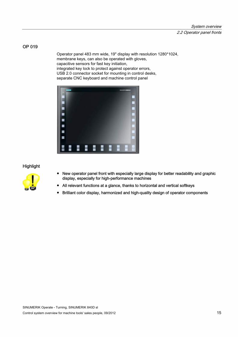
OP 015 Operator panel 483mm wide, 15" display, membrane keys, with frontal USB port for memory stick, separate CNC keyboard and machine control panel
Highlight ● Option of large display for better readability and graphic display, especially for high-
performance machines
● All relevant functions at a glance, thanks to horizontal and vertical softkeys
● Brilliant color display, harmonized and high-quality design of operator components
● Simple data handling with easily accessible USB memory stick
System overview 2.2 Operator panel fronts
SINUMERIK Operate - Turning, SINUMERIK 840D sl Control system overview for machine tools' sales people, 09/2012 15
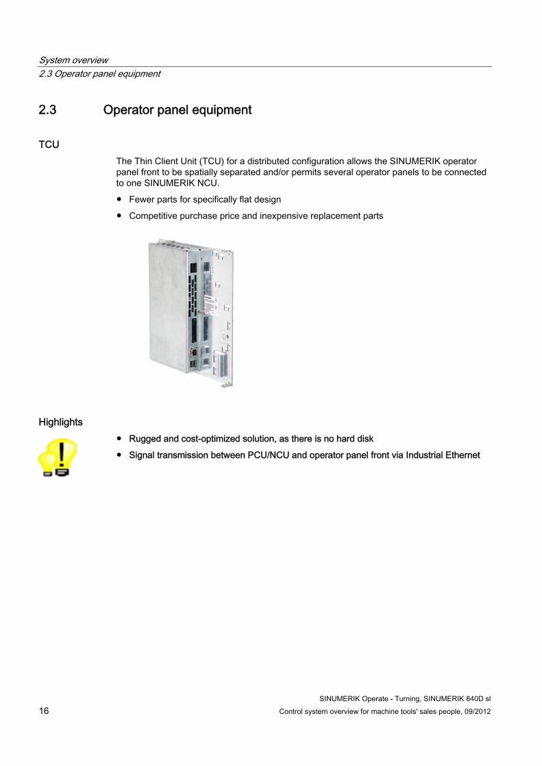
OP 019 Operator panel 483 mm wide, 19" display with resolution 1280*1024, membrane keys, can also be operated with gloves, capacitive sensors for fast key initiation, integrated key lock to protect against operator errors, USB 2.0 connector socket for mounting in control desks, separate CNC keyboard and machine control panel
Highlight ● New operator panel front with especially large display for better readability and graphic
display, especially for high-performance machines
● All relevant functions at a glance, thanks to horizontal and vertical softkeys
● Brilliant color display, harmonized and high-quality design of operator components
System overview 2.3 Operator panel equipment
SINUMERIK Operate - Turning, SINUMERIK 840D sl 16 Control system overview for machine tools' sales people, 09/2012
2.3 Operator panel equipment
TCU The Thin Client Unit (TCU) for a distributed configuration allows the SINUMERIK operator panel front to be spatially separated and/or permits several operator panels to be connected to one SINUMERIK NCU.
● Fewer parts for specifically flat design
● Competitive purchase price and inexpensive replacement parts
Highlights ● Rugged and cost-optimized solution, as there is no hard disk
● Signal transmission between PCU/NCU and operator panel front via Industrial Ethernet
System overview 2.3 Operator panel equipment
SINUMERIK Operate - Turning, SINUMERIK 840D sl Control system overview for machine tools' sales people, 09/2012 17
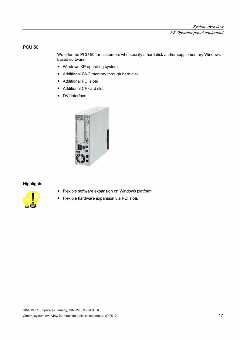
PCU 50 We offer the PCU 50 for customers who specify a hard disk and/or supplementary Windows-based software.
● Windows XP operating system
● Additional CNC memory through hard disk
● Additional PCI slots
● Additional CF card slot
● DVI interface
Highlights ● Flexible software expansion on Windows platform
● Flexible hardware expansion via PCI slots

System overview 2.3 Operator panel equipment
SINUMERIK Operate - Turning, SINUMERIK 840D sl 18 Control system overview for machine tools' sales people, 09/2012
SINUMERIK Operate - Turning, SINUMERIK 840D sl Control system overview for machine tools' sales people, 09/2012 19
CNC operation in manual mode (JOG) 33.1 TSM universal cycle
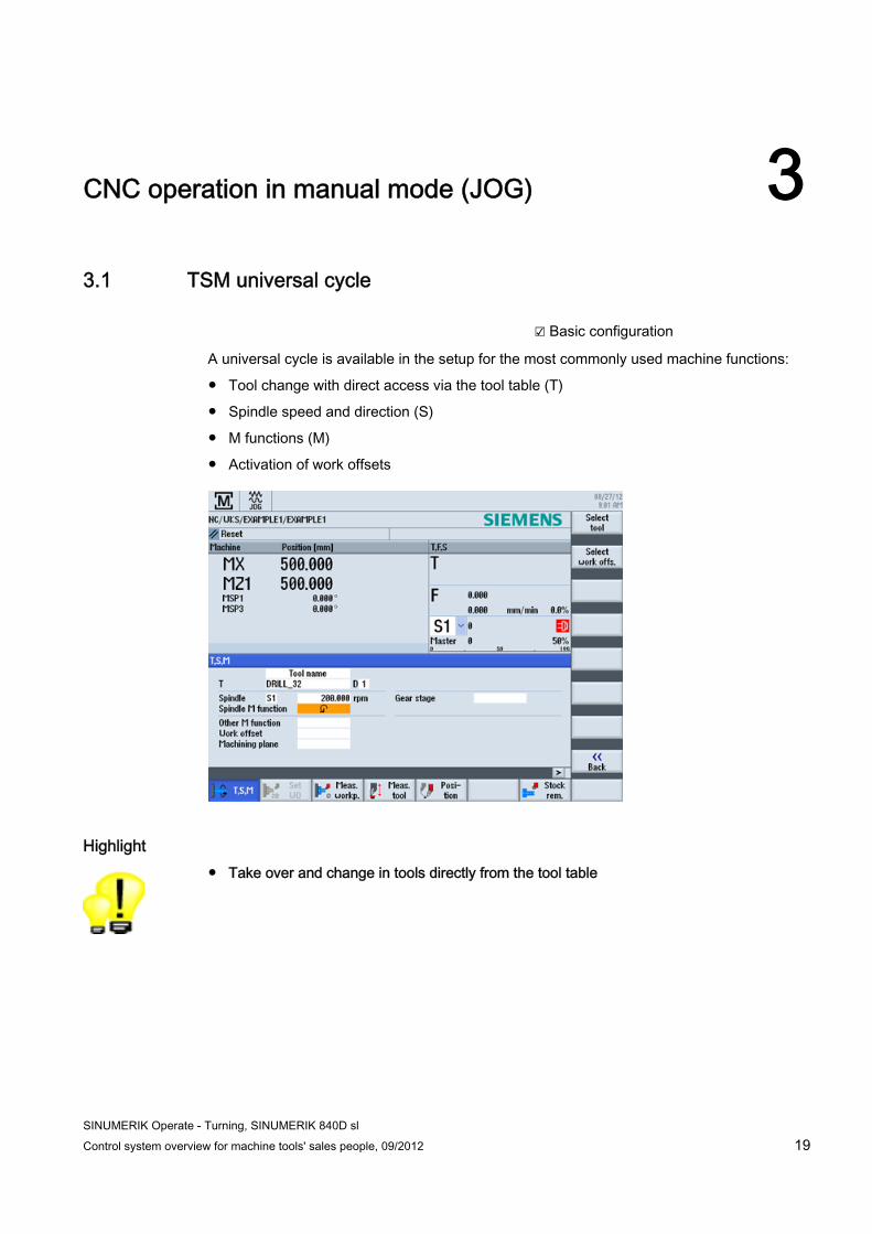
☑ Basic configuration
A universal cycle is available in the setup for the most commonly used machine functions:
● Tool change with direct access via the tool table (T)
● Spindle speed and direction (S)
● M functions (M)
● Activation of work offsets
Highlight ● Take over and change in tools directly from the tool table
CNC operation in manual mode (JOG) 3.2 Positioning cycle
SINUMERIK Operate - Turning, SINUMERIK 840D sl 20 Control system overview for machine tools' sales people, 09/2012
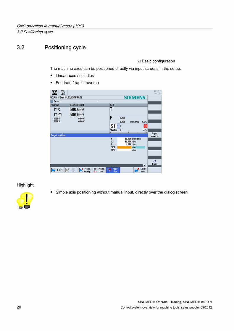
3.2 Positioning cycle ☑ Basic configuration
The machine axes can be positioned directly via input screens in the setup:
● Linear axes / spindles
● Feedrate / rapid traverse
Highlight ● Simple axis positioning without manual input, directly over the dialog screen
CNC operation in manual mode (JOG) 3.3 Stock removal cycle
SINUMERIK Operate - Turning, SINUMERIK 840D sl Control system overview for machine tools' sales people, 09/2012 21
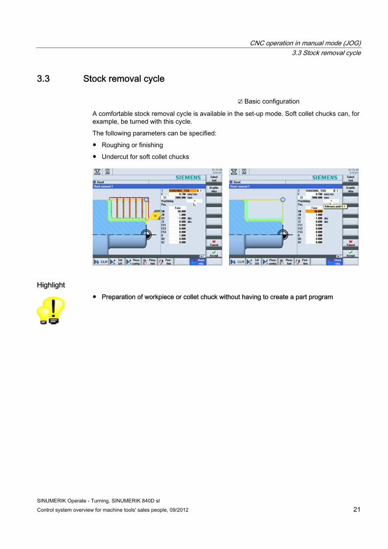
3.3 Stock removal cycle ☑ Basic configuration
A comfortable stock removal cycle is available in the set-up mode. Soft collet chucks can, for example, be turned with this cycle.
The following parameters can be specified:
● Roughing or finishing
● Undercut for soft collet chucks
Highlight ● Preparation of workpiece or collet chuck without having to create a part program
CNC operation in manual mode (JOG) 3.4 Measure tool
SINUMERIK Operate - Turning, SINUMERIK 840D sl 22 Control system overview for machine tools' sales people, 09/2012
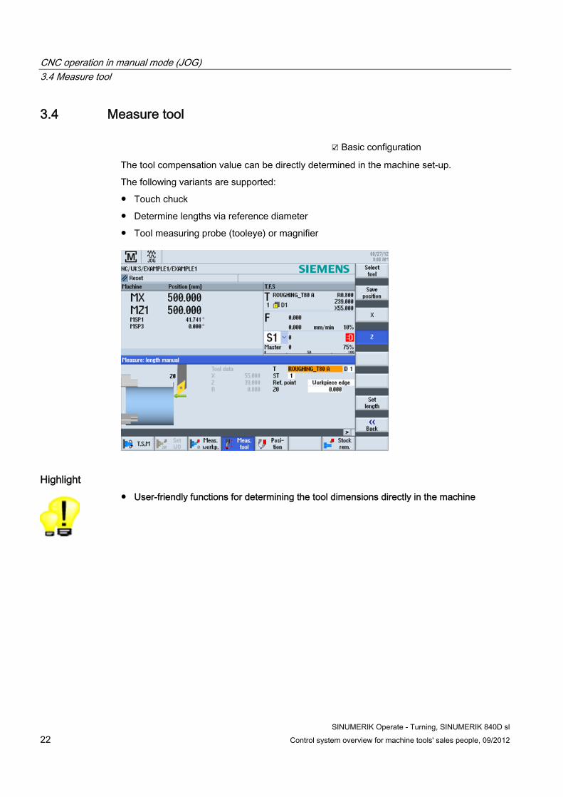
3.4 Measure tool ☑ Basic configuration
The tool compensation value can be directly determined in the machine set-up.
The following variants are supported:
● Touch chuck
● Determine lengths via reference diameter
● Tool measuring probe (tooleye) or magnifier
Highlight ● User-friendly functions for determining the tool dimensions directly in the machine
CNC operation in manual mode (JOG) 3.5 Measure workpiece
SINUMERIK Operate - Turning, SINUMERIK 840D sl Control system overview for machine tools' sales people, 09/2012 23
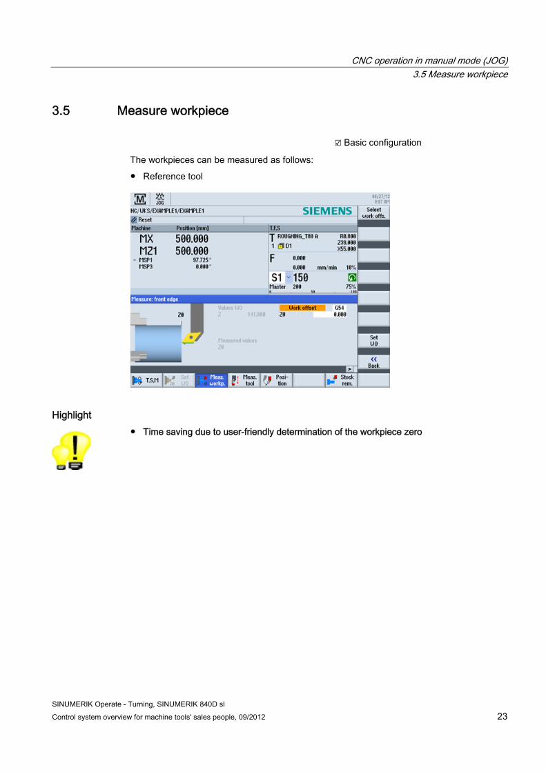
3.5 Measure workpiece ☑ Basic configuration
The workpieces can be measured as follows:
● Reference tool
Highlight ● Time saving due to user-friendly determination of the workpiece zero
CNC operation in manual mode (JOG) 3.6 Work offsets
SINUMERIK Operate - Turning, SINUMERIK 840D sl 24 Control system overview for machine tools' sales people, 09/2012
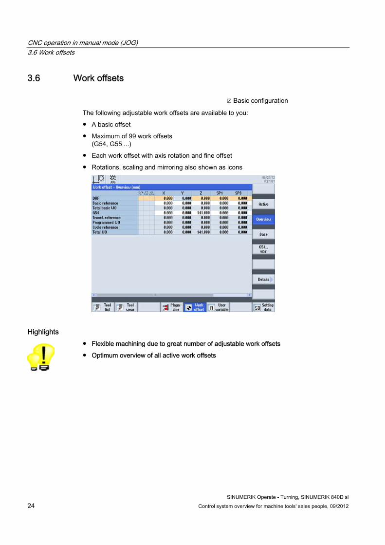
3.6 Work offsets ☑ Basic configuration
The following adjustable work offsets are available to you:
● A basic offset
● Maximum of 99 work offsets (G54, G55 ...)
● Each work offset with axis rotation and fine offset
● Rotations, scaling and mirroring also shown as icons
Highlights ● Flexible machining due to great number of adjustable work offsets
● Optimum overview of all active work offsets
SINUMERIK Operate - Turning, SINUMERIK 840D sl Control system overview for machine tools' sales people, 09/2012 25
Tool management 44.1 Tool table
☑ Basic configuration
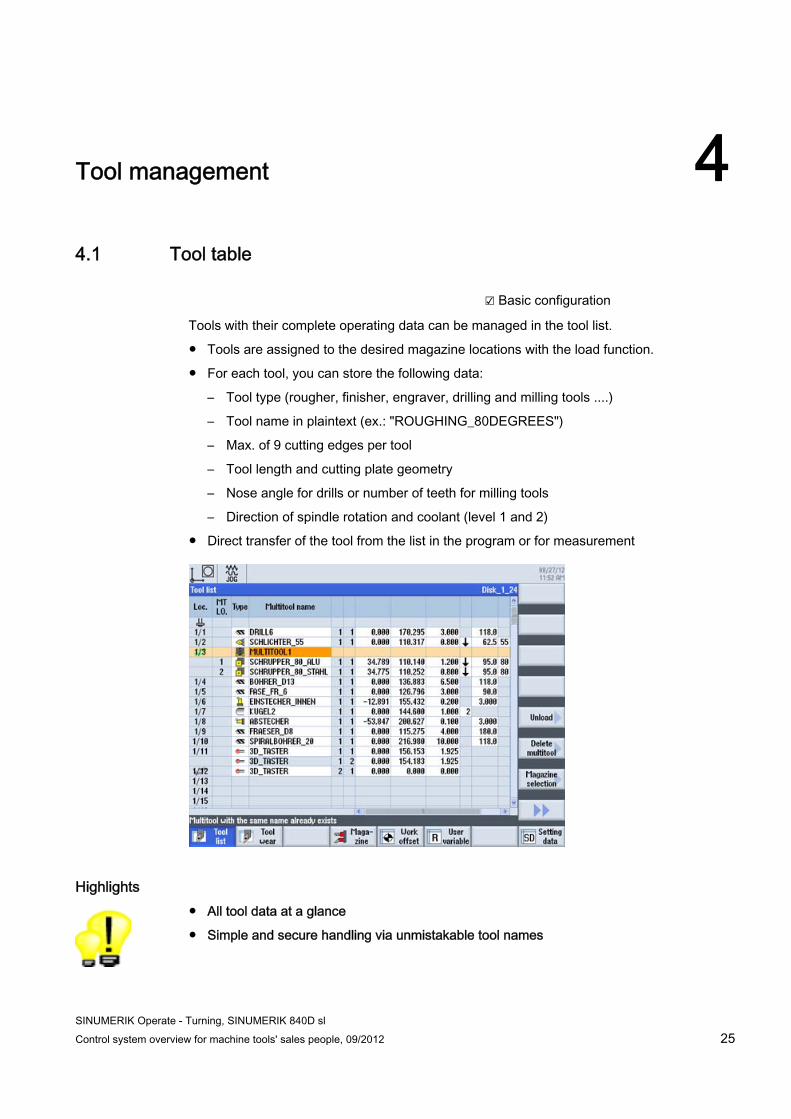
Tools with their complete operating data can be managed in the tool list.
● Tools are assigned to the desired magazine locations with the load function.
● For each tool, you can store the following data:
– Tool type (rougher, finisher, engraver, drilling and milling tools ....)
– Tool name in plaintext (ex.: "ROUGHING_80DEGREES")
– Max. of 9 cutting edges per tool
– Tool length and cutting plate geometry
– Nose angle for drills or number of teeth for milling tools
– Direction of spindle rotation and coolant (level 1 and 2)
● Direct transfer of the tool from the list in the program or for measurement
Highlights ● All tool data at a glance
● Simple and secure handling via unmistakable tool names
Tool management 4.2 Monitoring of tool life and workpiece count
SINUMERIK Operate - Turning, SINUMERIK 840D sl 26 Control system overview for machine tools' sales people, 09/2012
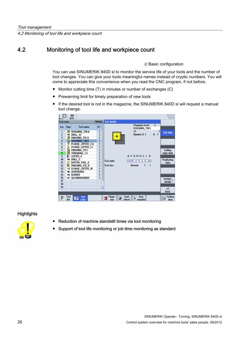
4.2 Monitoring of tool life and workpiece count ☑ Basic configuration
You can use SINUMERIK 840D sl to monitor the service life of your tools and the number of tool changes. You can give your tools meaningful names instead of cryptic numbers. You will come to appreciate this convenience when you read the CNC program, if not before.
● Monitor cutting time (T) in minutes or number of exchanges (C)
● Prewarning limit for timely preparation of new tools
● If the desired tool is not in the magazine, the SINUMERIK 840D sl will request a manual tool change.
Highlights ● Reduction of machine standstill times via tool monitoring
● Support of tool life monitoring or job time monitoring as standard
Tool management 4.3 Replacement tools
SINUMERIK Operate - Turning, SINUMERIK 840D sl Control system overview for machine tools' sales people, 09/2012 27
4.3 Replacement tools ☑ Basic configuration
If needed, you can even use the SINUMERIK 840D sl to manage replacement tools (sister tools). Tools with the same name are created as replacement tools. The replacement tools are identified with an incrementing number in the ST column.
Highlight ● Automatic tool exchange for unmanned operation
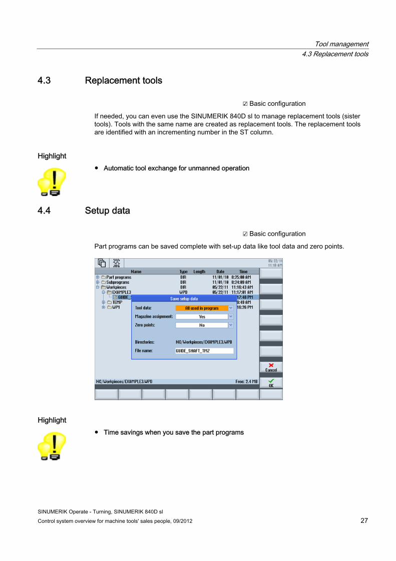
4.4 Setup data ☑ Basic configuration
Part programs can be saved complete with set-up data like tool data and zero points.
Highlight ● Time savings when you save the part programs
Tool management 4.4 Setup data
SINUMERIK Operate - Turning, SINUMERIK 840D sl 28 Control system overview for machine tools' sales people, 09/2012
SINUMERIK Operate - Turning, SINUMERIK 840D sl Control system overview for machine tools' sales people, 09/2012 29
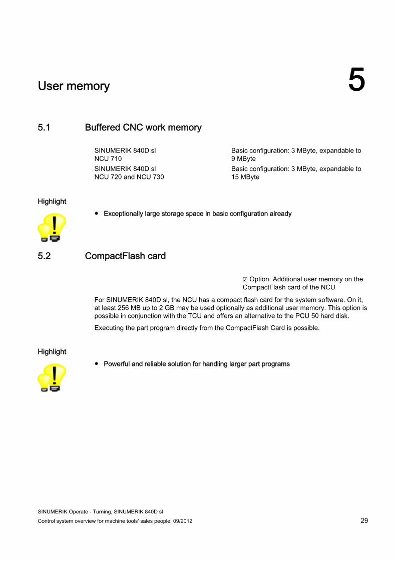
User memory 55.1 Buffered CNC work memory
SINUMERIK 840D sl NCU 710
Basic configuration: 3 MByte, expandable to 9 MByte
SINUMERIK 840D sl NCU 720 and NCU 730
Basic configuration: 3 MByte, expandable to 15 MByte
Highlight ● Exceptionally large storage space in basic configuration already
5.2 CompactFlash card ☑ Option: Additional user memory on the
CompactFlash card of the NCU
For SINUMERIK 840D sl, the NCU has a compact flash card for the system software. On it, at least 256 MB up to 2 GB may be used optionally as additional user memory. This option is possible in conjunction with the TCU and offers an alternative to the PCU 50 hard disk.
Executing the part program directly from the CompactFlash Card is possible.
Highlight ● Powerful and reliable solution for handling larger part programs
User memory 5.3 Hard disk
SINUMERIK Operate - Turning, SINUMERIK 840D sl 30 Control system overview for machine tools' sales people, 09/2012
5.3 Hard disk ☑ Option: PCU 50
A hard disk with 12 GB of user memory is available on the PCU 50 for expansion of the CNC memory.
Highlights ● Hard disk can still be used as a data carrier
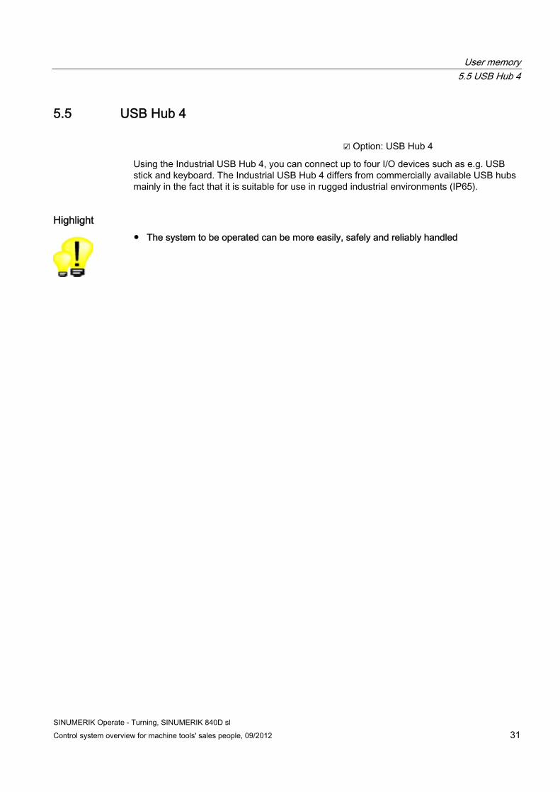
5.4 Card reader ☑ Option: Card reader
Using the SINUMERIK card reading unit in combination with CF, SD and MMC cards, data can be archived and user data exchanged. The connection is made via a USB interface. The card reader can be booted. Cards can be inserted and removed during operation.
Highlights ● Insertion and removal of cards during operation possible
● Simple data exchange without opening the control cabinet
User memory 5.5 USB Hub 4
SINUMERIK Operate - Turning, SINUMERIK 840D sl Control system overview for machine tools' sales people, 09/2012 31
5.5 USB Hub 4 ☑ Option: USB Hub 4
Using the Industrial USB Hub 4, you can connect up to four I/O devices such as e.g. USB stick and keyboard. The Industrial USB Hub 4 differs from commercially available USB hubs mainly in the fact that it is suitable for use in rugged industrial environments (IP65).
Highlight ● The system to be operated can be more easily, safely and reliably handled

User memory 5.5 USB Hub 4
SINUMERIK Operate - Turning, SINUMERIK 840D sl 32 Control system overview for machine tools' sales people, 09/2012
SINUMERIK Operate - Turning, SINUMERIK 840D sl Control system overview for machine tools' sales people, 09/2012 33
Data transfer 66.1 Program manager
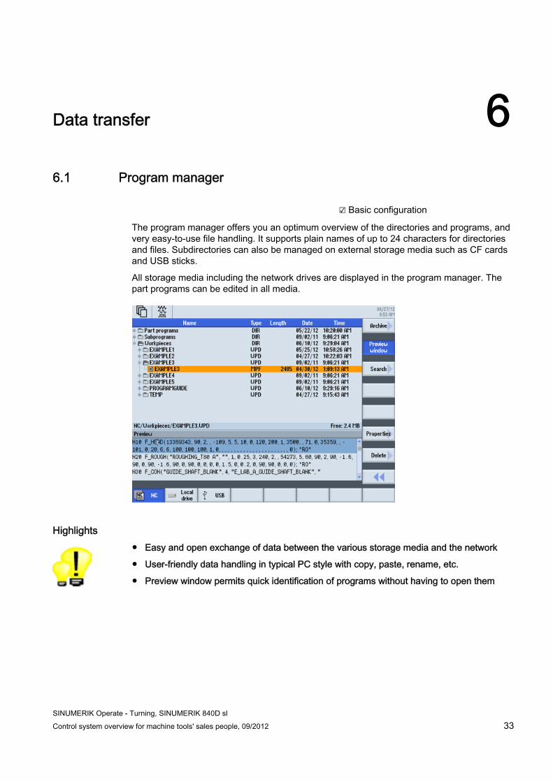
☑ Basic configuration
The program manager offers you an optimum overview of the directories and programs, and very easy-to-use file handling. It supports plain names of up to 24 characters for directories and files. Subdirectories can also be managed on external storage media such as CF cards and USB sticks.
All storage media including the network drives are displayed in the program manager. The part programs can be edited in all media.
Highlights ● Easy and open exchange of data between the various storage media and the network
● User-friendly data handling in typical PC style with copy, paste, rename, etc.
● Preview window permits quick identification of programs without having to open them
Data transfer 6.2 Data transfer using the USB memory stick
SINUMERIK Operate - Turning, SINUMERIK 840D sl 34 Control system overview for machine tools' sales people, 09/2012
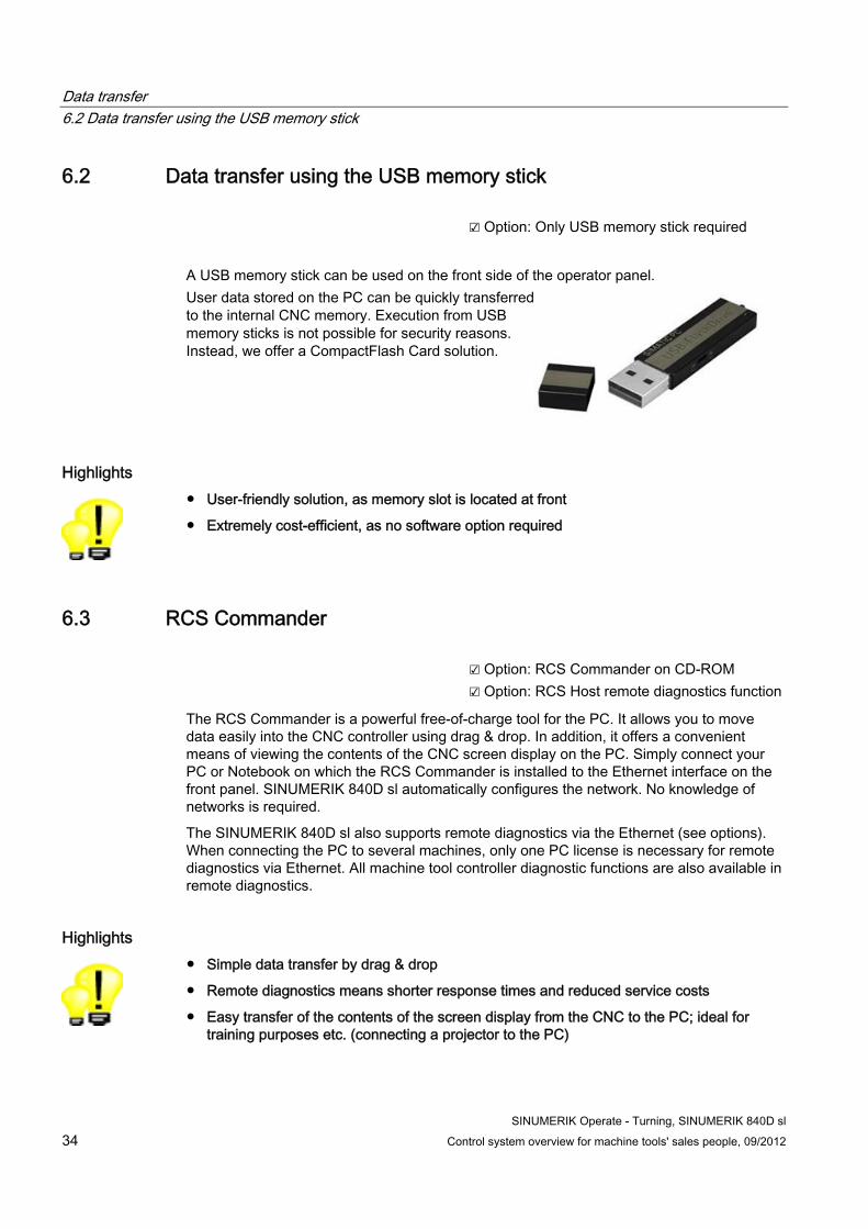
6.2 Data transfer using the USB memory stick ☑ Option: Only USB memory stick required
A USB memory stick can be used on the front side of the operator panel. User data stored on the PC can be quickly transferred to the internal CNC memory. Execution from USB memory sticks is not possible for security reasons. Instead, we offer a CompactFlash Card solution.
Highlights ● User-friendly solution, as memory slot is located at front
● Extremely cost-efficient, as no software option required
6.3 RCS Commander ☑ Option: RCS Commander on CD-ROM
☑ Option: RCS Host remote diagnostics function
The RCS Commander is a powerful free-of-charge tool for the PC. It allows you to move data easily into the CNC controller using drag & drop. In addition, it offers a convenient means of viewing the contents of the CNC screen display on the PC. Simply connect your PC or Notebook on which the RCS Commander is installed to the Ethernet interface on the front panel. SINUMERIK 840D sl automatically configures the network. No knowledge of networks is required.
The SINUMERIK 840D sl also supports remote diagnostics via the Ethernet (see options). When connecting the PC to several machines, only one PC license is necessary for remote diagnostics via Ethernet. All machine tool controller diagnostic functions are also available in remote diagnostics.
Highlights ● Simple data transfer by drag & drop
● Remote diagnostics means shorter response times and reduced service costs
● Easy transfer of the contents of the screen display from the CNC to the PC; ideal for training purposes etc. (connecting a projector to the PC)
Data transfer 6.4 Ethernet networking
SINUMERIK Operate - Turning, SINUMERIK 840D sl Control system overview for machine tools' sales people, 09/2012 35
6.4 Ethernet networking ☑ Basic configuration
The SINUMERIK 840D sl is set up for Ethernet (TCP/IP) networking (RJ45 connection).
● The data transfer rate is 10/100 Mbps.
● Remote access to the controller via the RCS Commander, e.g. for commissioning and remote diagnostics
● Access to the network drives is available directly from the program manager. No additional software is required on the server.
Highlight ● Favorably-priced and simple connection to Windows PCs via Ethernet (TCP/IP)
● No software needs to be installed on the servers
Data transfer 6.4 Ethernet networking
SINUMERIK Operate - Turning, SINUMERIK 840D sl 36 Control system overview for machine tools' sales people, 09/2012
SINUMERIK Operate - Turning, SINUMERIK 840D sl Control system overview for machine tools' sales people, 09/2012 37
Graphical support functions 77.1 Animated Elements
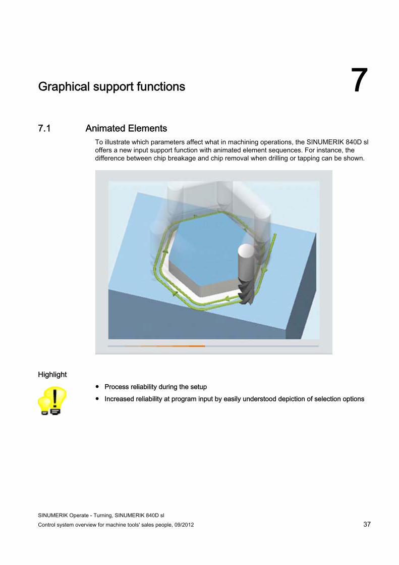
To illustrate which parameters affect what in machining operations, the SINUMERIK 840D sl offers a new input support function with animated element sequences. For instance, the difference between chip breakage and chip removal when drilling or tapping can be shown.
Highlight ● Process reliability during the setup
● Increased reliability at program input by easily understood depiction of selection options
Graphical support functions 7.2 Onboard documentation
SINUMERIK Operate - Turning, SINUMERIK 840D sl 38 Control system overview for machine tools' sales people, 09/2012
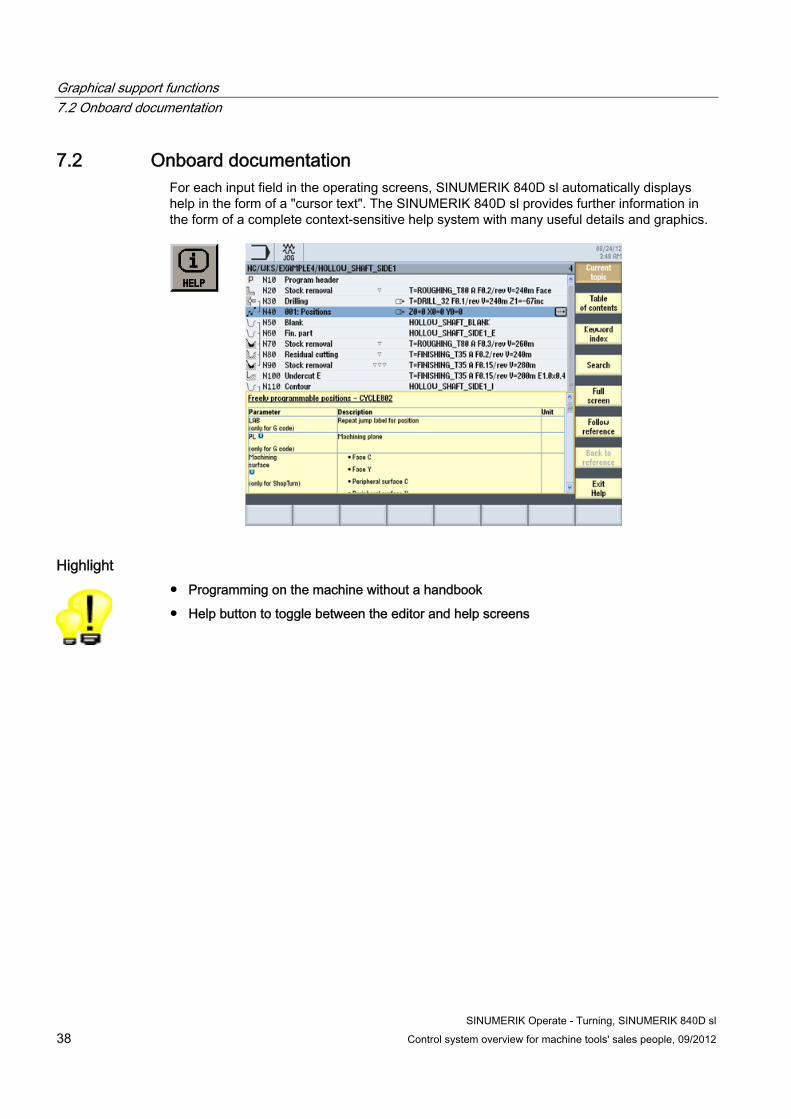
7.2 Onboard documentation For each input field in the operating screens, SINUMERIK 840D sl automatically displays help in the form of a "cursor text". The SINUMERIK 840D sl provides further information in the form of a complete context-sensitive help system with many useful details and graphics.
Highlight ● Programming on the machine without a handbook
● Help button to toggle between the editor and help screens
SINUMERIK Operate - Turning, SINUMERIK 840D sl Control system overview for machine tools' sales people, 09/2012 39
CNC operation in automatic mode (AUTO) 88.1 Block search
☑ Basic configuration
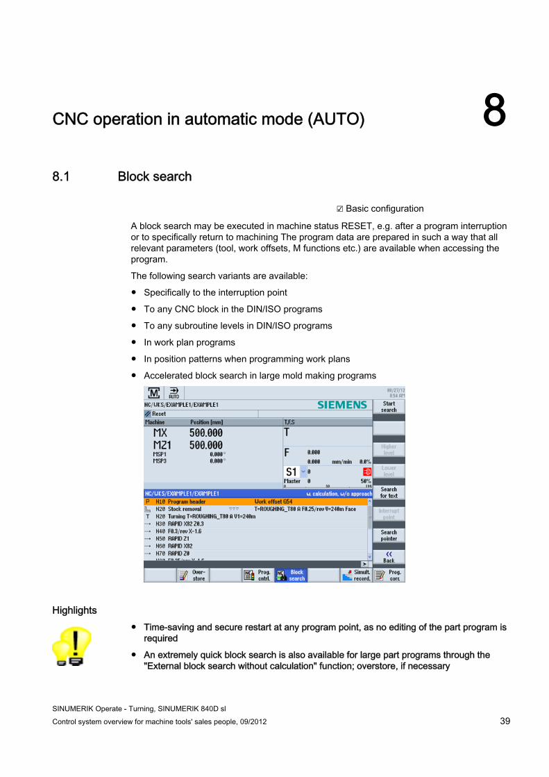
A block search may be executed in machine status RESET, e.g. after a program interruption or to specifically return to machining The program data are prepared in such a way that all relevant parameters (tool, work offsets, M functions etc.) are available when accessing the program.
The following search variants are available:
● Specifically to the interruption point
● To any CNC block in the DIN/ISO programs
● To any subroutine levels in DIN/ISO programs
● In work plan programs
● In position patterns when programming work plans
● Accelerated block search in large mold making programs
Highlights ● Time-saving and secure restart at any program point, as no editing of the part program is
required
● An extremely quick block search is also available for large part programs through the "External block search without calculation" function; overstore, if necessary
CNC operation in automatic mode (AUTO) 8.2 Basic block display
SINUMERIK Operate - Turning, SINUMERIK 840D sl 40 Control system overview for machine tools' sales people, 09/2012
8.2 Basic block display ☑ Basic configuration
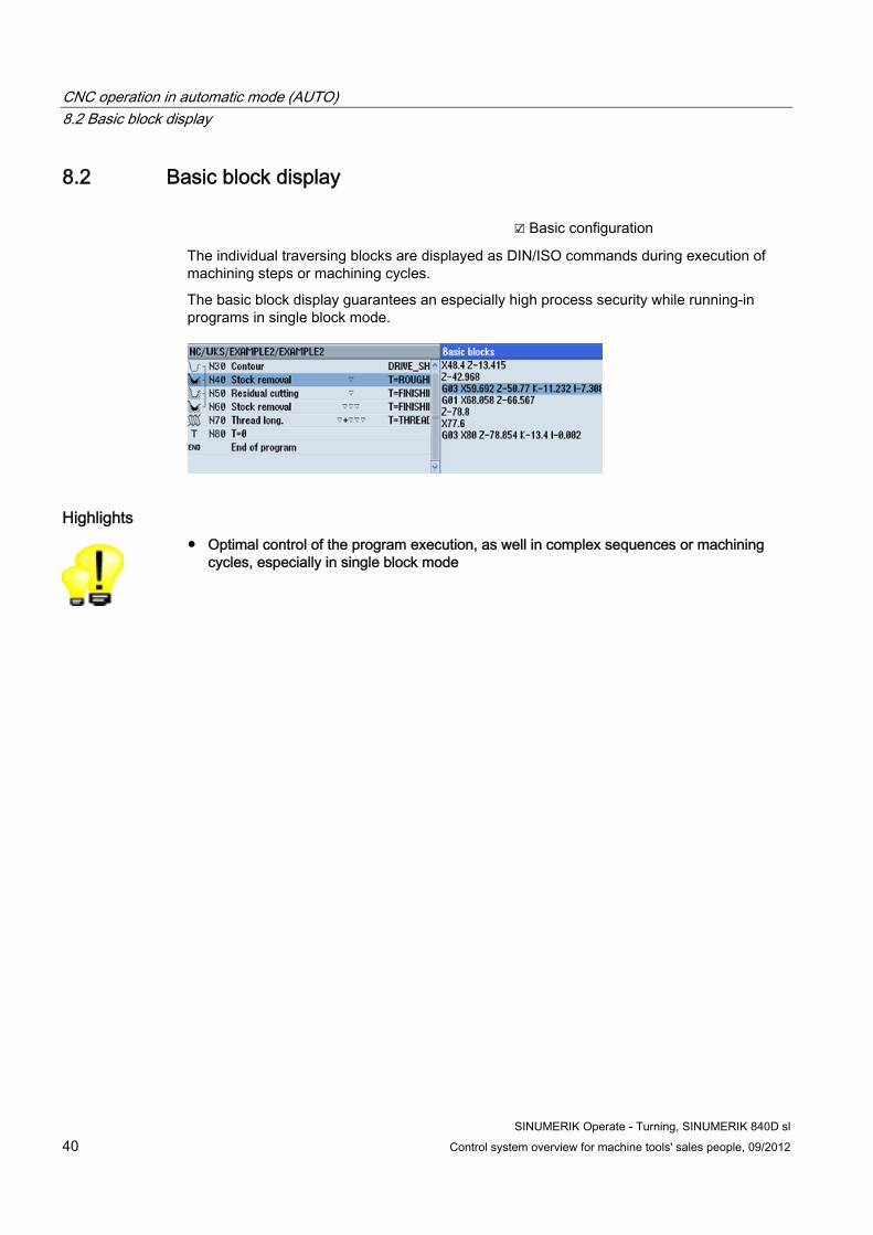
The individual traversing blocks are displayed as DIN/ISO commands during execution of machining steps or machining cycles.
The basic block display guarantees an especially high process security while running-in programs in single block mode.
Highlights ● Optimal control of the program execution, as well in complex sequences or machining
cycles, especially in single block mode
CNC operation in automatic mode (AUTO) 8.3 Program control
SINUMERIK Operate - Turning, SINUMERIK 840D sl Control system overview for machine tools' sales people, 09/2012 41
8.3 Program control ☑ Basic configuration
Single block
Single block mode can be activated for startup of the program. For this purpose a program stop occurs after each traversing block. Work plan programs maintain the alternative of stopping processing after each plane infeed.
Program test
Programs can be checked before processing in a program test mode. The program is executed to completion with stationary axes. This is especially meaningful in connection with the simultaneous recording option (real-time simulation).
Reduced rapid traverse
You have the facility of additionally limiting the traversing speed for rapid traverse so that when running-in a new program with rapid traverse, no undesirable high traversing speeds occur. In the rapid traverse mode, the traversing speed of the axes is reduced to the percentage value (0-100%) entered in RG0.
Program editing
In machine condition STOP, the program can be edited directly at the location of the fault, e.g. erroneous DIN/ISO blocks or wrongly parameterized sequences. After correcting the program you can continue machining.
Repositioning to the contour (REPOS)
In machine condition STOP, the machining axes may be moved to and away from the workpiece surface with the handwheel or the direction keys.
Highlights ● Secure positioning of new part programs
● Continue machining quickly after interruptions
CNC operation in automatic mode (AUTO) 8.4 Simultaneous recording
SINUMERIK Operate - Turning, SINUMERIK 840D sl 42 Control system overview for machine tools' sales people, 09/2012
8.4 Simultaneous recording ☑ Option: Simultaneous recording
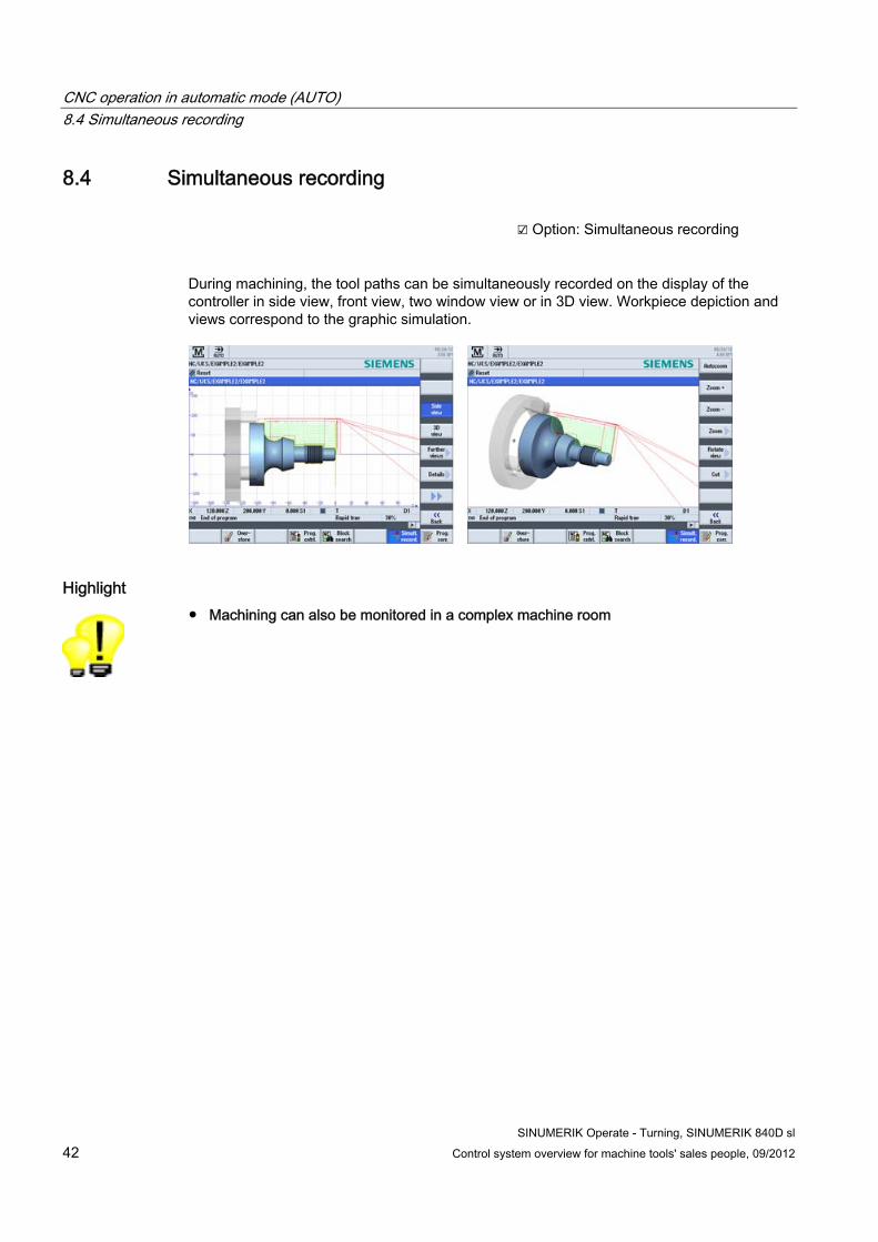
During machining, the tool paths can be simultaneously recorded on the display of the controller in side view, front view, two window view or in 3D view. Workpiece depiction and views correspond to the graphic simulation.
Highlight ● Machining can also be monitored in a complex machine room
SINUMERIK Operate - Turning, SINUMERIK 840D sl Control system overview for machine tools' sales people, 09/2012 43
CNC performance capability and optimization functions 99.1 80bit NANOFP accuracy
☑ Basic configuration
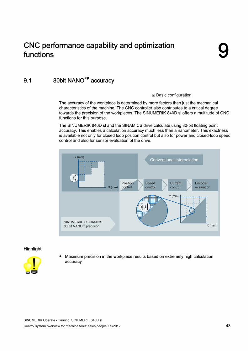
The accuracy of the workpiece is determined by more factors than just the mechanical characteristics of the machine. The CNC controller also contributes to a critical degree towards the precision of the workpieces. The SINUMERIK 840D sl offers a multitude of CNC functions for this purpose.
The SINUMERIK 840D sl and the SINAMICS drive calculate using 80-bit floating point accuracy. This enables a calculation accuracy much less than a nanometer. This exactness is available not only for closed loop position control but also for power and closed-loop speed control and also for sensor evaluation of the drive.
Y (mm)
Y (mm)
X (mm)
X (mm)
1 m
m
0.00
1 m
m
Highlight ● Maximum precision in the workpiece results based on extremely high calculation
accuracy
CNC performance capability and optimization functions 9.2 Jerk limitation
SINUMERIK Operate - Turning, SINUMERIK 840D sl 44 Control system overview for machine tools' sales people, 09/2012
9.2 Jerk limitation ☑ Basic configuration
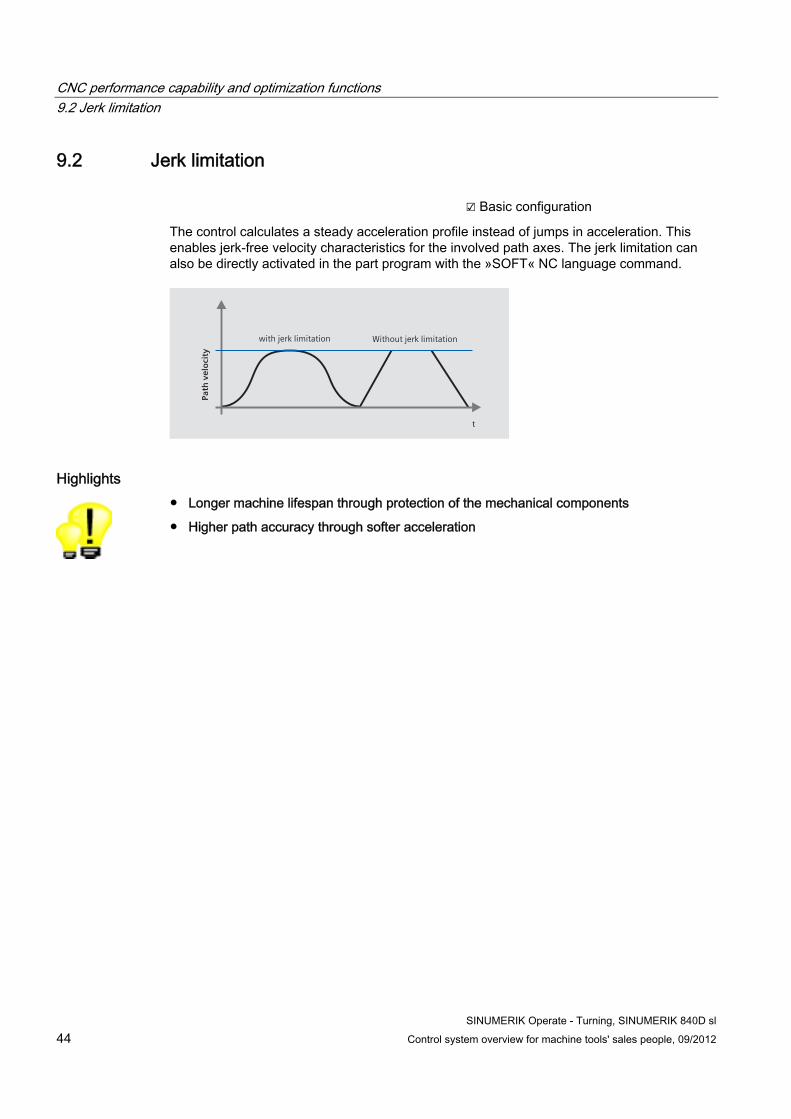
The control calculates a steady acceleration profile instead of jumps in acceleration. This enables jerk-free velocity characteristics for the involved path axes. The jerk limitation can also be directly activated in the part program with the »SOFT« NC language command.
t
with jerk limitation Without jerk limitation
Path
vel
oci
ty
Highlights ● Longer machine lifespan through protection of the mechanical components
● Higher path accuracy through softer acceleration
CNC performance capability and optimization functions 9.3 Dynamic feedforward control
SINUMERIK Operate - Turning, SINUMERIK 840D sl Control system overview for machine tools' sales people, 09/2012 45
9.3 Dynamic feedforward control ☑ Basic configuration
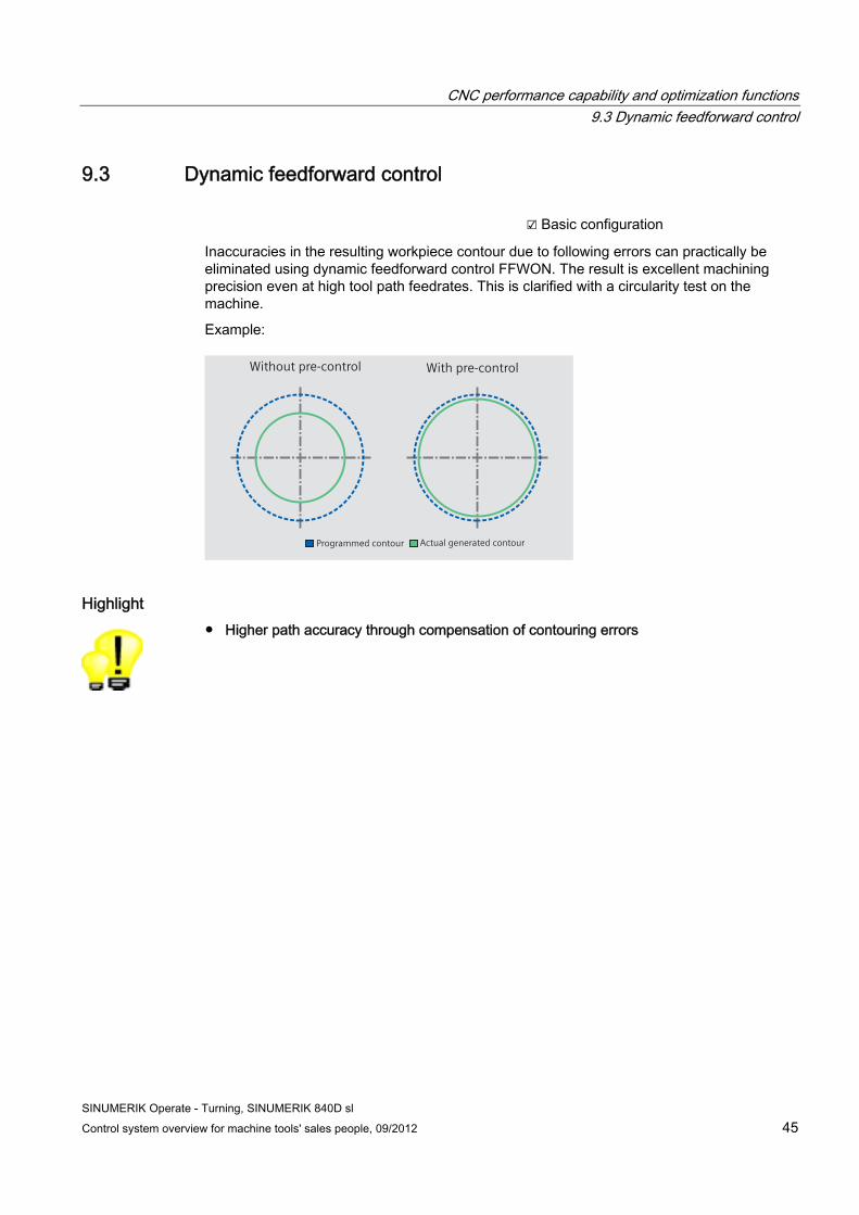
Inaccuracies in the resulting workpiece contour due to following errors can practically be eliminated using dynamic feedforward control FFWON. The result is excellent machining precision even at high tool path feedrates. This is clarified with a circularity test on the machine.
Example:
With pre-controlWithout pre-control
Actual generated contourProgrammed contour
Highlight ● Higher path accuracy through compensation of contouring errors
CNC performance capability and optimization functions 9.4 Look Ahead
SINUMERIK Operate - Turning, SINUMERIK 840D sl 46 Control system overview for machine tools' sales people, 09/2012
9.4 Look Ahead ☑ Basic configuration
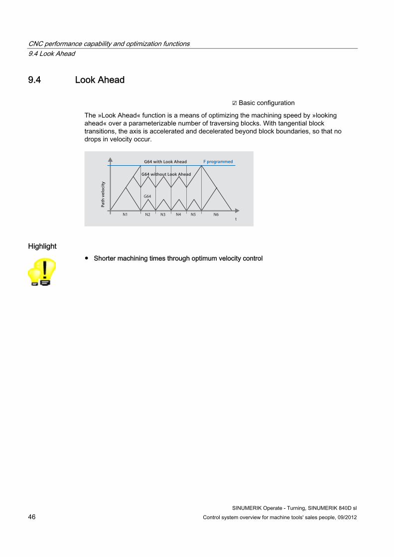
The »Look Ahead« function is a means of optimizing the machining speed by »looking ahead« over a parameterizable number of traversing blocks. With tangential block transitions, the axis is accelerated and decelerated beyond block boundaries, so that no drops in velocity occur.
G64
t
Path
vel
oci
ty
N2 N4N3N1 N5 N6
F programmedG64 with Look Ahead
G64 without Look Ahead
Highlight ● Shorter machining times through optimum velocity control
SINUMERIK Operate - Turning, SINUMERIK 840D sl Control system overview for machine tools' sales people, 09/2012 47
CNC programming methods 1010.1 Overview of programming methods
The SINUMERIK 840D sl offers you a choice of the following programming methods:
programGUIDE and SINUMERIK CNC programming
With programGUIDE you obtain the perfect combination of the SINUMERIK CNC programming language and the parameterization of technology cycles. The wide choice of technology cycles and the ease of parameterization allows you to reduce the programming time. The parameter input is supported by Animated Elements.
The SINUMERIK language statements with CNC high-level language elements offer you a very high degree of flexibility and guarantee minimum machining time.
programmGUIDE and SINUMERIK CNC programming are particularly suitable for medium series and large series production.
ShopTurn - Machining step programming
Machining operations such as stock removal, grooving or thread cutting are shown in ShopTurn in the form of worksteps. In this way CNC programs – even for complex machining operations – are very compact and easily read. Associated sequences are automatically interlinked and can be assigned any position patterns. ShopTurn offers you the shortest programming times even for highly demanding machining tasks. The parameter input is supported by Animated Elements.
ShopTurn is particularly well suited for small series production.
ISO dialect and SINUMERIK CNC programming language
The SINUMERIK 840D sl allows you to perform ISO programming using the SINUMERIK CNC programming language combined with or exclusively in ISO dialect.
The online ISO dialect interpreter offers you the opportunity to use CNC programs from other manufacturers.
Step for step you can increase the performance capability by using SINUMERIK CNC programming.
Highlights ● Whether you use programGUIDE or ShopTurn – in either case the full range of
technological cycles, position patterns and geometries is available to you
● Compatibility with the ISO dialect of other controller manufacturers is feasible

CNC programming methods 10.2 programGUIDE and SINUMERIK CNC programming
SINUMERIK Operate - Turning, SINUMERIK 840D sl 48 Control system overview for machine tools' sales people, 09/2012
10.2 programGUIDE and SINUMERIK CNC programming
10.2.1 Introduction ☑ Basic configuration
Below is an overview of the characteristic functions of programGUIDE and SINUMERIK CNC programming. This includes:
● DIN/ISO editor
● Languages
● programGUIDE input support
Programming with programGUIDE is available in the basic scope of the SINUMERIK 840D sl.
10.2.2 Program editor A line-oriented program editor is available to you for DIN/ISO programming. The editor enables you to input CNC language commands directly or to edit them. Thereby, the complete range of CNC functions are available for the most complex machining. The following functions are included in the program editor: • Contour calculator • Tool selection directly from tool list • Support screens for standard machining
and measuring cycles • "Copy", "Insert" and "Cut" key group • "Find", "Replace" and "Replace All"
character string • Renumbering a program • Direct execution from any NC program
block (block search) • Jump to program start or program end
Highlights ● Time saving by using a powerful editor when programming
● Even large part programs allow extremely fast editing in MB size
CNC programming methods 10.2 programGUIDE and SINUMERIK CNC programming
SINUMERIK Operate - Turning, SINUMERIK 840D sl Control system overview for machine tools' sales people, 09/2012 49
10.2.3 Languages The SINUMERIK 840D sI's CNC interpreter can also process more complex CNC commands, in addition to DIN 66025 standard commands. The commands are presented in clearly readable form.
The following commands are available:
● G-code G-code in accordance with DIN 66025 and in ISO dialect mode
● G functions G0, G1, G2, G71 ...
● Language commands (extended G functions) CIP, SOFT, BRISK, FFWON ...
● Frame operations (programmable work offsets) The workpiece coordinate system can be shifted, scaled, mirrored or rotated with the commands TRANS, SCALE, MIRROR, ROT.
● R parameters (arithmetic parameters) 300 predefined R parameters are available as arithmetic parameters (floating point format).
● User variables The user can define his own variables by name and type.
● System variables System variables can be read/written in all programs. They enable access to work offsets, tool offsets, axis positions, measurement values, control conditions etc.
● Calculation operations The following mathematical calculation operations are available for linking the variables: calculation operations + - * / sin cos exp etc. logical operations == <> >= etc.
● Program control structures BASIC-style language commands are available for flexible programming of the user cycles: IF-ELSE-ENDIF, FOR, CASE ...
Highlights ● Established programming according to DIN 66025
● Unbeatable range of commands for flexibility and time saving while programming

CNC programming methods 10.2 programGUIDE and SINUMERIK CNC programming
SINUMERIK Operate - Turning, SINUMERIK 840D sl 50 Control system overview for machine tools' sales people, 09/2012
10.2.4 programGUIDE input support The cycle support is an extension of the highly flexible DIN/ISO programming. The input screens are based on the ShopTurn cycles input screens, so as to ensure optimum continuity.
The calls for tool, feedrate and spindle speed can of course also be input in the DIN/ISO editor.
Highlights ● Existing DIN/ISO part programs with cycles can continue to be used
● Minimum learning requirements due to the continuity of the input support
CNC programming methods 10.3 ShopTurn
SINUMERIK Operate - Turning, SINUMERIK 840D sl Control system overview for machine tools' sales people, 09/2012 51
10.3 ShopTurn
10.3.1 Introduction ☑ Option: Machining step programming ShopTurn
The following information provides you with an overview of the characteristic functions of ShopTurn. This includes:
● Sequence editor
● Interlinking of sequences
● Broken-line graphics
These functions are part of the machining step programming options package in ShopTurn.
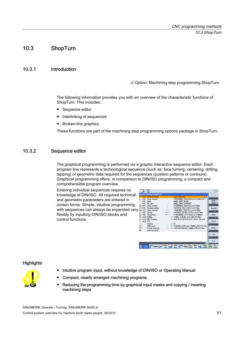
10.3.2 Sequence editor The graphical programming is performed via a graphic interactive sequence editor. Each program line represents a technological sequence (such as: face turning, centering, drilling, tapping) or geometric data required for the sequences (position patterns or contours). Graphical programming offers, in comparison to DIN/ISO programming, a compact and comprehensible program overview. Entering individual sequences requires no knowledge of DIN/ISO. All required technical and geometric parameters are entered in screen forms. Simple, intuitive programming with sequences can always be expanded very flexibly by inputting DIN/ISO blocks and control functions.
Highlights ● Intuitive program input, without knowledge of DIN/ISO or Operating Manual
● Compact, clearly arranged machining programs
● Reducing the programming time by graphical input masks and copying / inserting machining steps
CNC programming methods 10.3 ShopTurn
SINUMERIK Operate - Turning, SINUMERIK 840D sl 52 Control system overview for machine tools' sales people, 09/2012
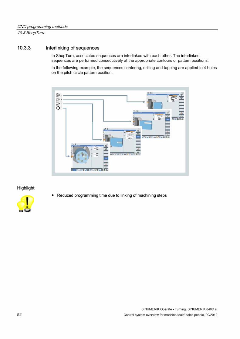
10.3.3 Interlinking of sequences In ShopTurn, associated sequences are interlinked with each other. The interlinked sequences are performed consecutively at the appropriate contours or pattern positions.
In the following example, the sequences centering, drilling and tapping are applied to 4 holes on the pitch circle pattern position.
Highlight ● Reduced programming time due to linking of machining steps

CNC programming methods 10.3 ShopTurn
SINUMERIK Operate - Turning, SINUMERIK 840D sl Control system overview for machine tools' sales people, 09/2012 53
10.3.4 Broken-line graphics While programming, the previously entered sequences will be continuously displayed to scale. A simulation is not required for this. The switch over between the sequence program and the broken-line graphics is performed by the "Graphics View" softkey.
● Turning view
● Front face and peripheral side
Highlight ● Increased reliability at program input by quickly checking the contour, without having to
start a simulation run

CNC programming methods 10.4 Online ISO dialect interpreter
SINUMERIK Operate - Turning, SINUMERIK 840D sl 54 Control system overview for machine tools' sales people, 09/2012
10.4 Online ISO dialect interpreter ☑ Basic configuration
It is always useful to be able to speak a foreign language. This is true even for a global player such as the SINUMERIK 840D sl. If you prefer classic ISO programming you can continue to use it. You can even mix ISO programming with the SINUMERIK CNC programming language. This enables you to increase the productivity and flexibility of your machine step by step.
In the controller, G commands from Siemens are interpreted as standard.
ISO dialect codes and Siemens codes can be mixed within a part program, but not within an NC block.
The switch over between Siemens operating mode and ISO dialect is performed using the following two G commands:
● G290 - "Siemens" NC programming language active
● G291 - "ISO dialect" NC programming language active
The performance capability of the ISO dialect extends even as far as using the cycles G73 to G89, such as cycle G84 for tapping.
Highlights ● Even first-time users can initially continue programming the way they are accustomed to
● ISO dialect and SINUMERIK CNC programming languages can be mixed within part programs
SINUMERIK Operate - Turning, SINUMERIK 840D sl Control system overview for machine tools' sales people, 09/2012 55
Simulation 1111.1 2D simulation
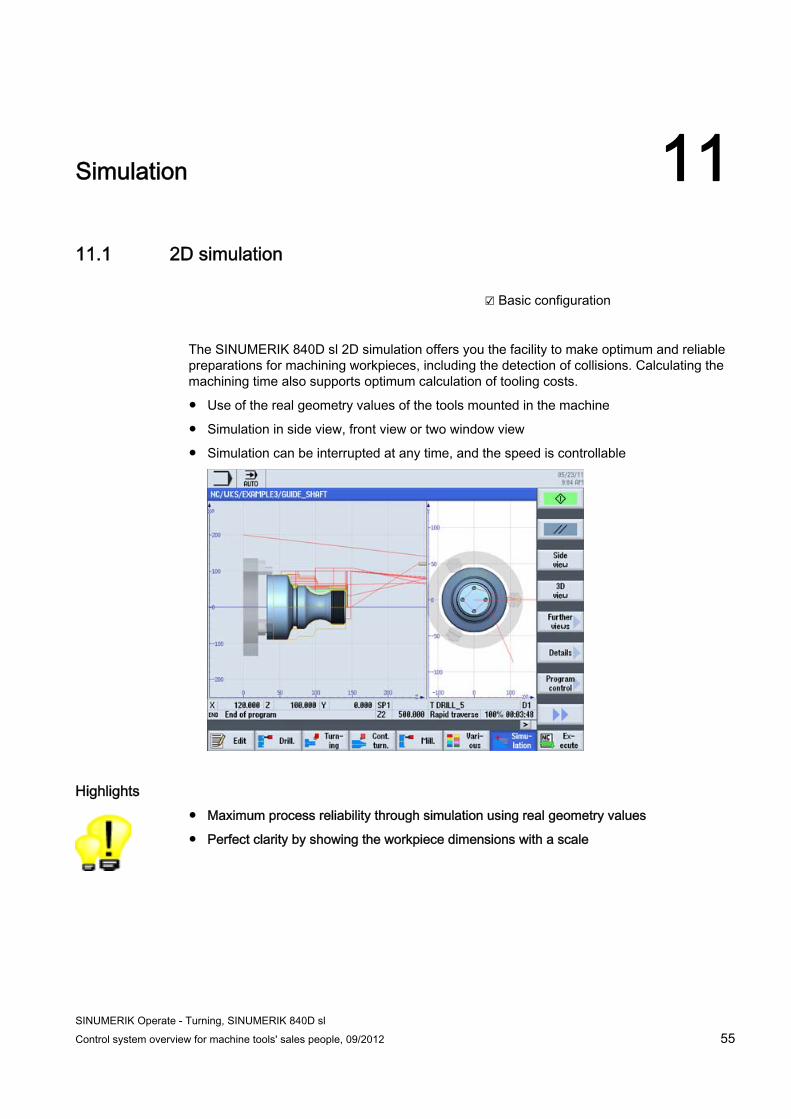
☑ Basic configuration
The SINUMERIK 840D sl 2D simulation offers you the facility to make optimum and reliable preparations for machining workpieces, including the detection of collisions. Calculating the machining time also supports optimum calculation of tooling costs.
● Use of the real geometry values of the tools mounted in the machine
● Simulation in side view, front view or two window view
● Simulation can be interrupted at any time, and the speed is controllable
Highlights ● Maximum process reliability through simulation using real geometry values
● Perfect clarity by showing the workpiece dimensions with a scale
Simulation 11.2 3D simulation
SINUMERIK Operate - Turning, SINUMERIK 840D sl 56 Control system overview for machine tools' sales people, 09/2012
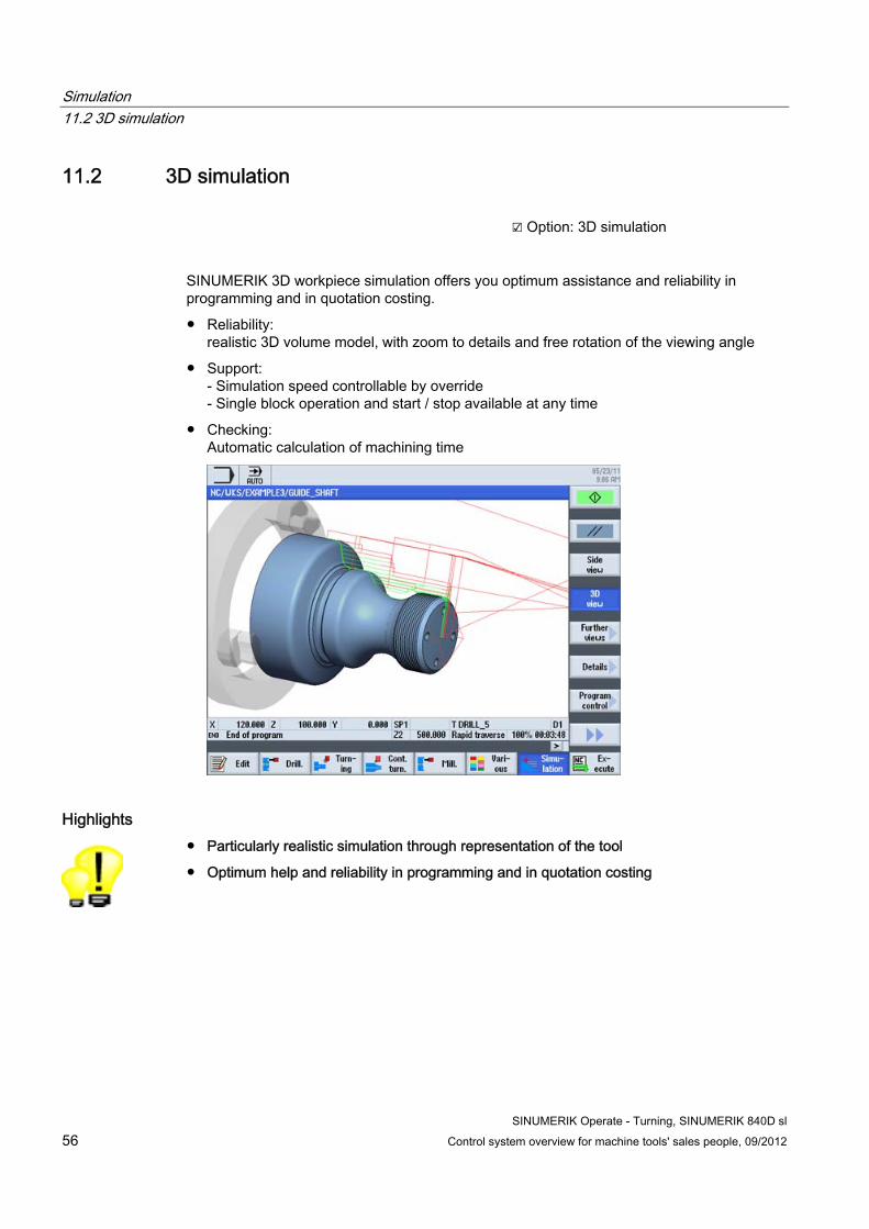
11.2 3D simulation ☑ Option: 3D simulation
SINUMERIK 3D workpiece simulation offers you optimum assistance and reliability in programming and in quotation costing.
● Reliability: realistic 3D volume model, with zoom to details and free rotation of the viewing angle
● Support: - Simulation speed controllable by override - Single block operation and start / stop available at any time
● Checking: Automatic calculation of machining time
Highlights ● Particularly realistic simulation through representation of the tool
● Optimum help and reliability in programming and in quotation costing
SINUMERIK Operate - Turning, SINUMERIK 840D sl Control system overview for machine tools' sales people, 09/2012 57
CNC technology cycles 12
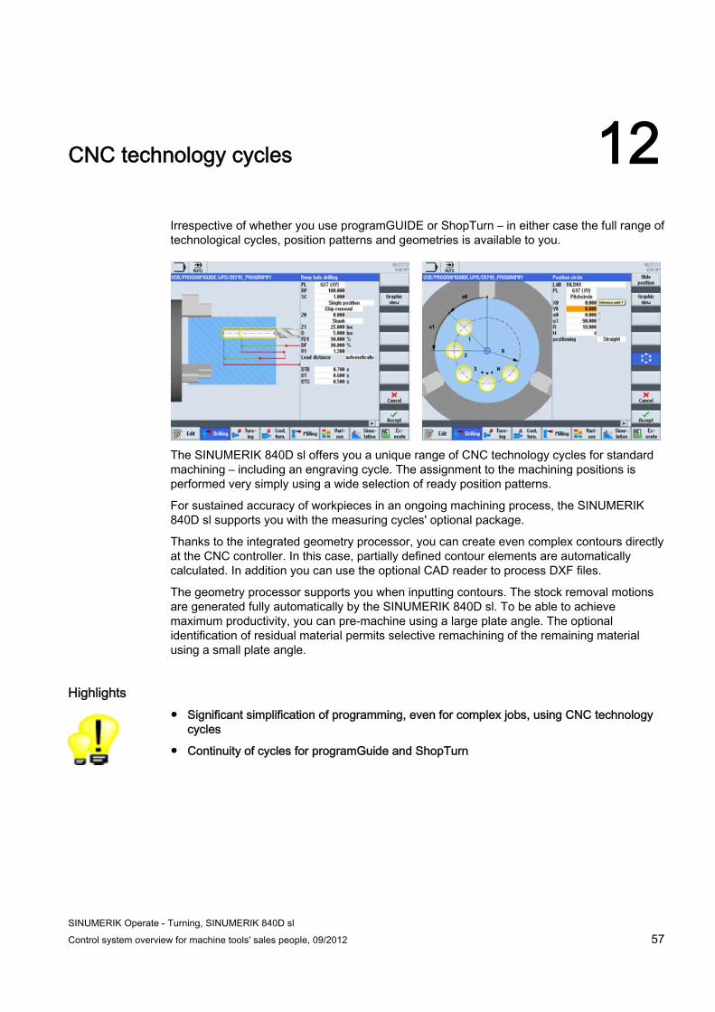
Irrespective of whether you use programGUIDE or ShopTurn – in either case the full range of technological cycles, position patterns and geometries is available to you.
The SINUMERIK 840D sl offers you a unique range of CNC technology cycles for standard machining – including an engraving cycle. The assignment to the machining positions is performed very simply using a wide selection of ready position patterns.
For sustained accuracy of workpieces in an ongoing machining process, the SINUMERIK 840D sl supports you with the measuring cycles' optional package.
Thanks to the integrated geometry processor, you can create even complex contours directly at the CNC controller. In this case, partially defined contour elements are automatically calculated. In addition you can use the optional CAD reader to process DXF files.
The geometry processor supports you when inputting contours. The stock removal motions are generated fully automatically by the SINUMERIK 840D sl. To be able to achieve maximum productivity, you can pre-machine using a large plate angle. The optional identification of residual material permits selective remachining of the remaining material using a small plate angle.
Highlights ● Significant simplification of programming, even for complex jobs, using CNC technology
cycles
● Continuity of cycles for programGuide and ShopTurn
CNC technology cycles 12.1 Highlights of machining cycles
SINUMERIK Operate - Turning, SINUMERIK 840D sl 58 Control system overview for machine tools' sales people, 09/2012
12.1 Highlights of machining cycles
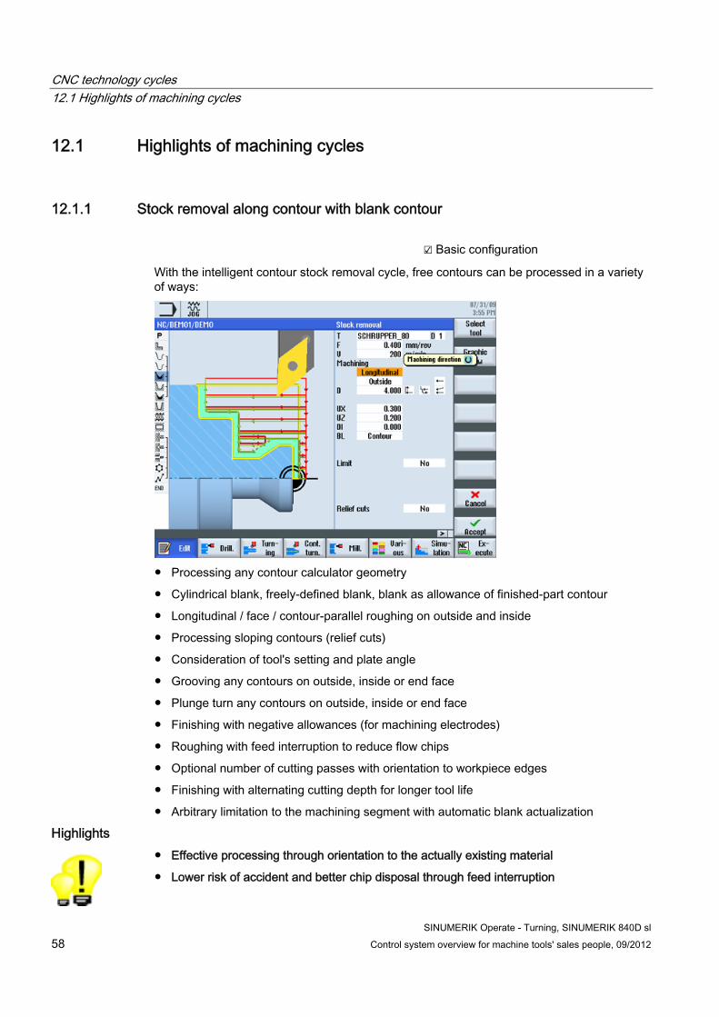
12.1.1 Stock removal along contour with blank contour ☑ Basic configuration
With the intelligent contour stock removal cycle, free contours can be processed in a variety of ways:
● Processing any contour calculator geometry
● Cylindrical blank, freely-defined blank, blank as allowance of finished-part contour
● Longitudinal / face / contour-parallel roughing on outside and inside
● Processing sloping contours (relief cuts)
● Consideration of tool's setting and plate angle
● Grooving any contours on outside, inside or end face
● Plunge turn any contours on outside, inside or end face
● Finishing with negative allowances (for machining electrodes)
● Roughing with feed interruption to reduce flow chips
● Optional number of cutting passes with orientation to workpiece edges
● Finishing with alternating cutting depth for longer tool life
● Arbitrary limitation to the machining segment with automatic blank actualization
Highlights ● Effective processing through orientation to the actually existing material
● Lower risk of accident and better chip disposal through feed interruption
CNC technology cycles 12.1 Highlights of machining cycles
SINUMERIK Operate - Turning, SINUMERIK 840D sl Control system overview for machine tools' sales people, 09/2012 59
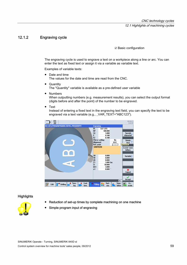
12.1.2 Engraving cycle ☑ Basic configuration
The engraving cycle is used to engrave a text on a workpiece along a line or arc. You can enter the text as fixed text or assign it via a variable as variable text.
Examples of variable texts:
● Date and time The values for the date and time are read from the CNC.
● Quantity The "Quantity" variable is available as a pre-defined user variable
● Numbers When outputting numbers (e.g. measurement results), you can select the output format (digits before and after the point) of the number to be engraved.
● Text Instead of entering a fixed text in the engraving text field, you can specify the text to be engraved via a text variable (e.g., _VAR_TEXT="ABC123").
Highlights ● Reduction of set-up times by complete machining on one machine
● Simple program input of engraving
CNC technology cycles 12.1 Highlights of machining cycles
SINUMERIK Operate - Turning, SINUMERIK 840D sl 60 Control system overview for machine tools' sales people, 09/2012
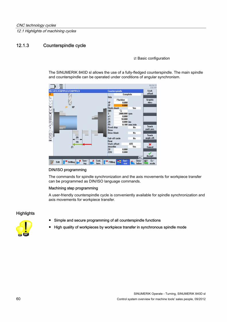
12.1.3 Counterspindle cycle ☑ Basic configuration
The SINUMERIK 840D sl allows the use of a fully-fledged counterspindle. The main spindle and counterspindle can be operated under conditions of angular synchronism.
DIN/ISO programming
The commands for spindle synchronization and the axis movements for workpiece transfer can be programmed as DIN/ISO language commands.
Machining step programming
A user-friendly counterspindle cycle is conveniently available for spindle synchronization and axis movements for workpiece transfer.
Highlights ● Simple and secure programming of all counterspindle functions
● High quality of workpieces by workpiece transfer in synchronous spindle mode
CNC technology cycles 12.2 Residual material detection
SINUMERIK Operate - Turning, SINUMERIK 840D sl Control system overview for machine tools' sales people, 09/2012 61
12.2 Residual material detection
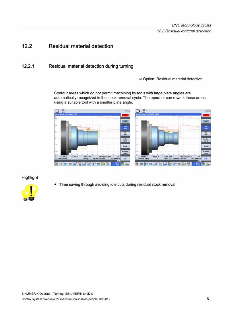
12.2.1 Residual material detection during turning ☑ Option: Residual material detection
Contour areas which do not permit machining by tools with large plate angles are automatically recognized in the stock removal cycle. The operator can rework these areas using a suitable tool with a smaller plate angle.
Highlight ● Time saving through avoiding idle cuts during residual stock removal
CNC technology cycles 12.2 Residual material detection
SINUMERIK Operate - Turning, SINUMERIK 840D sl 62 Control system overview for machine tools' sales people, 09/2012
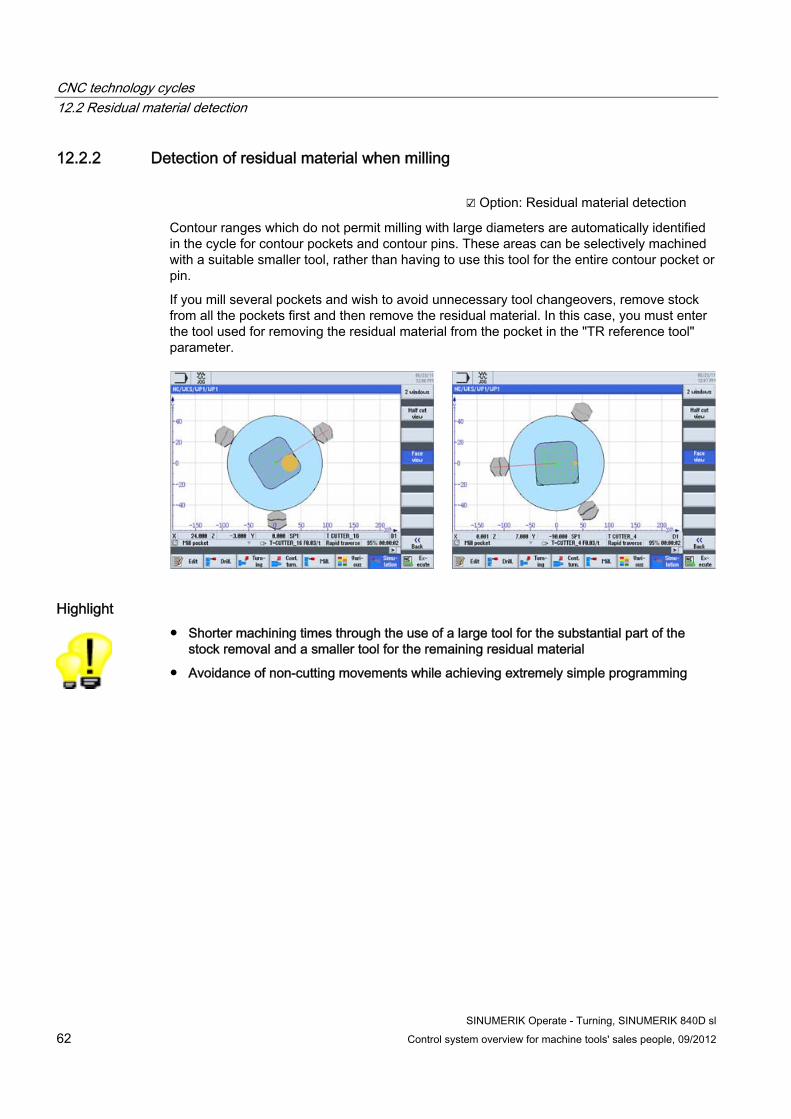
12.2.2 Detection of residual material when milling ☑ Option: Residual material detection
Contour ranges which do not permit milling with large diameters are automatically identified in the cycle for contour pockets and contour pins. These areas can be selectively machined with a suitable smaller tool, rather than having to use this tool for the entire contour pocket or pin.
If you mill several pockets and wish to avoid unnecessary tool changeovers, remove stock from all the pockets first and then remove the residual material. In this case, you must enter the tool used for removing the residual material from the pocket in the "TR reference tool" parameter.
Highlight ● Shorter machining times through the use of a large tool for the substantial part of the
stock removal and a smaller tool for the remaining residual material
● Avoidance of non-cutting movements while achieving extremely simple programming

CNC technology cycles 12.3 In-process measuring for workpieces and tools
SINUMERIK Operate - Turning, SINUMERIK 840D sl Control system overview for machine tools' sales people, 09/2012 63
12.3 In-process measuring for workpieces and tools ☑ Option: Measuring cycles
For measurement tasks in automatic mode, powerful measuring cycles are available both within the sequence and also in DIN/ISO programming. Input screens with dynamic help displays are used for convenient entry of the measuring parameters.
The following cycles are available for workpiece measurement:
The following measurement variants are available for tool measurement:
● Calibration of the tool probe
● Determation of the tool length of turning tools and drills
● Determation of length/radius/length and radius of milling tools on a turning machine
The following measuring tasks can be made:
● Automatic value correction for tool geometry or work offset
● Display of measurement results
● Logging of measurement results
Highlights ● Reliable quality of the manufactured parts by automatic measurement in the machine
● Fast programming for complex measuring tasks thanks to input screens with graphic support
CNC technology cycles 12.3 In-process measuring for workpieces and tools
SINUMERIK Operate - Turning, SINUMERIK 840D sl 64 Control system overview for machine tools' sales people, 09/2012
SINUMERIK Operate - Turning, SINUMERIK 840D sl Control system overview for machine tools' sales people, 09/2012 65
Complete machining 1313.1 End face machining (TRANSMIT)
☑ Option: TRANSMIT and peripheral
surface transformation
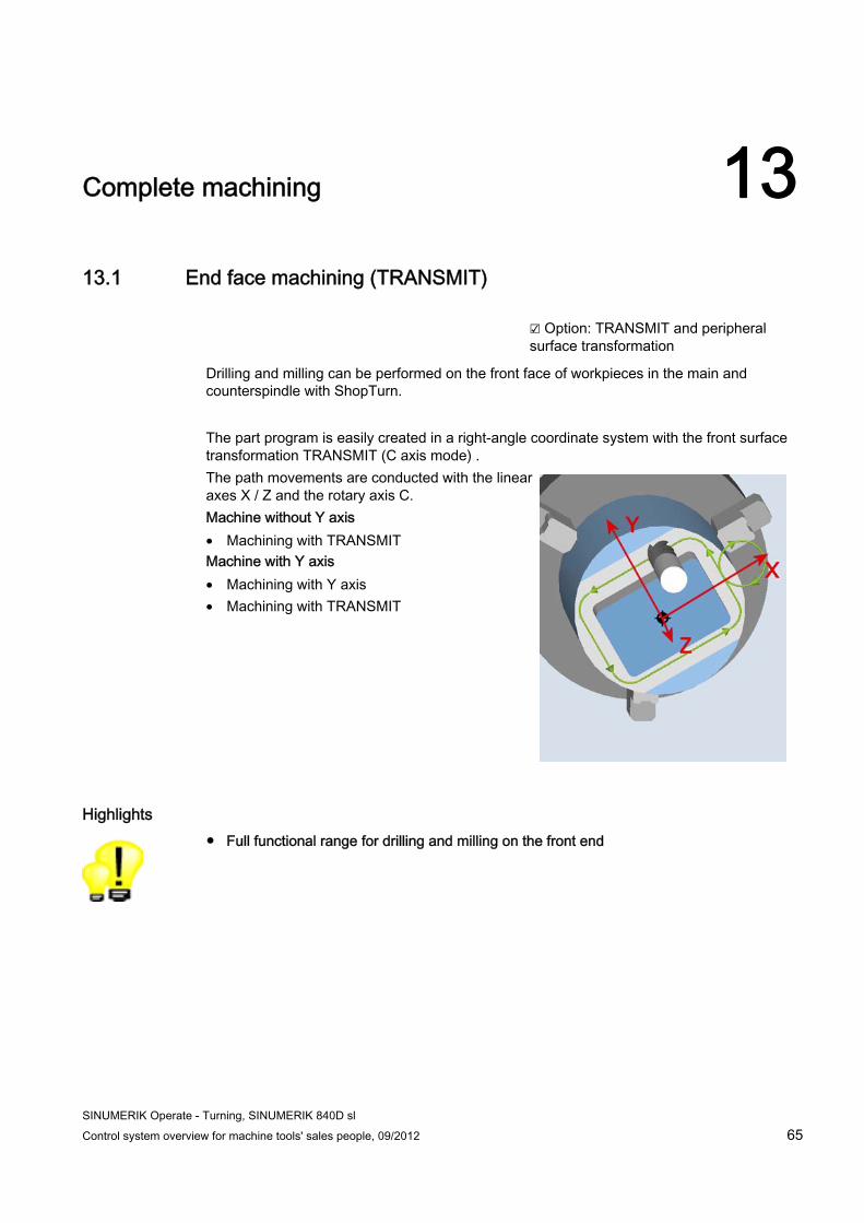
Drilling and milling can be performed on the front face of workpieces in the main and counterspindle with ShopTurn.
The part program is easily created in a right-angle coordinate system with the front surface transformation TRANSMIT (C axis mode) . The path movements are conducted with the linear axes X / Z and the rotary axis C. Machine without Y axis • Machining with TRANSMIT Machine with Y axis • Machining with Y axis • Machining with TRANSMIT
Highlights ● Full functional range for drilling and milling on the front end

Complete machining 13.2 Peripheral surface machining (TRACYL)
SINUMERIK Operate - Turning, SINUMERIK 840D sl 66 Control system overview for machine tools' sales people, 09/2012
13.2 Peripheral surface machining (TRACYL) ☑ Option: TRANSMIT and peripheral
surface transformation
Using the peripheral surface transformation TRACYL, drilling and milling machining can be executed on the peripheral surface of workpieces in the main and counterspindle. Machine without Y axis • Any drill holes on the peripheral surface • Any milling without slot wall offset on the
peripheral surface Machine with Y axis • Any drill holes on the peripheral surface • Any milling without slot wall offset on the
peripheral surface • Any milling with slot wall offset on the peripheral
surface • Grooving on parallel walls of the peripheral
surface with milling radius correction
Highlights ● Full functional range for drilling and milling on the peripheral surface
● Reduction of set-up times by complete machining on one machine
SINUMERIK Operate - Turning, SINUMERIK 840D sl Control system overview for machine tools' sales people, 09/2012 67
Multi-channel machining 1414.1 Overview
☑ Option: programSYNC (multi-channel)
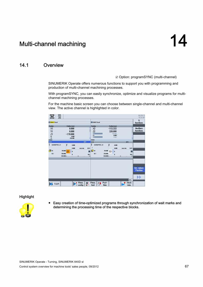
SINUMERIK Operate offers numerous functions to support you with programming and production of multi-channel machining processes.
With programSYNC, you can easily synchronize, optimize and visualize programs for multi-channel machining processes.
For the machine basic screen you can choose between single-channel and multi-channel view. The active channel is highlighted in color.
Highlight ● Easy creation of time-optimized programs through synchronization of wait marks and
determining the processing time of the respective blocks.
Multi-channel machining 14.2 programSYNC job list
SINUMERIK Operate - Turning, SINUMERIK 840D sl 68 Control system overview for machine tools' sales people, 09/2012
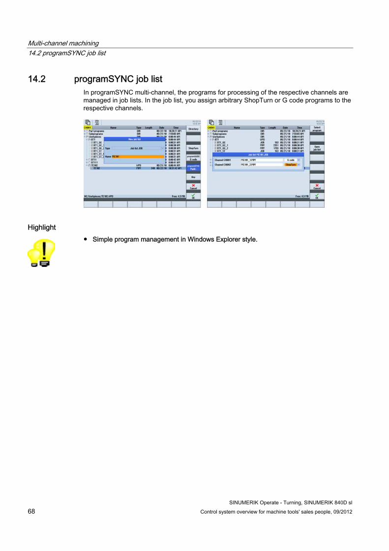
14.2 programSYNC job list In programSYNC multi-channel, the programs for processing of the respective channels are managed in job lists. In the job list, you assign arbitrary ShopTurn or G code programs to the respective channels.
Highlight ● Simple program management in Windows Explorer style.

Multi-channel machining 14.3 Double editor
SINUMERIK Operate - Turning, SINUMERIK 840D sl Control system overview for machine tools' sales people, 09/2012 69
14.3 Double editor The double editor facilitates the creation of the programs for the respective channels.
● You structure the programs by means of blocks. These can be expanded and collapsed for a clear representation.
● In the double editor, you can program the chronological sequence and check the wait marks through the synchronized view.
● Through the automatic time evaluation, you can further optimize the multi-channel program in the double editor. If required, you can transfer individual machining processes to other channels to create a time-optimized program.
Highlight ● SINUMERIK supports the easy handling of complex machines.

Multi-channel machining 14.4 Simulation
SINUMERIK Operate - Turning, SINUMERIK 840D sl 70 Control system overview for machine tools' sales people, 09/2012
14.4 Simulation For the simulation, you can select, among other things, machining on the main spindle and counterspindle and choose between different views, including 3D view.
Highlight ● With the workpiece simulation, SINUMERIK offers optimum help and safety for
programming - even during parallel machining.
SINUMERIK Operate - Turning, SINUMERIK 840D sl Control system overview for machine tools' sales people, 09/2012 71
PC software 1515.1 CAD reader for PC
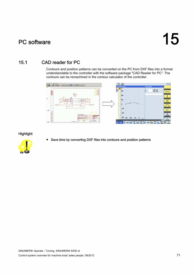
Contours and position patterns can be converted on the PC from DXF files into a format understandable to the controller with the software package "CAD Reader for PC". The contours can be remachined in the contour calculator of the controller.
Highlight ● Save time by converting DXF files into contours and position patterns
PC software 15.2 SinuTrain
SINUMERIK Operate - Turning, SINUMERIK 840D sl 72 Control system overview for machine tools' sales people, 09/2012
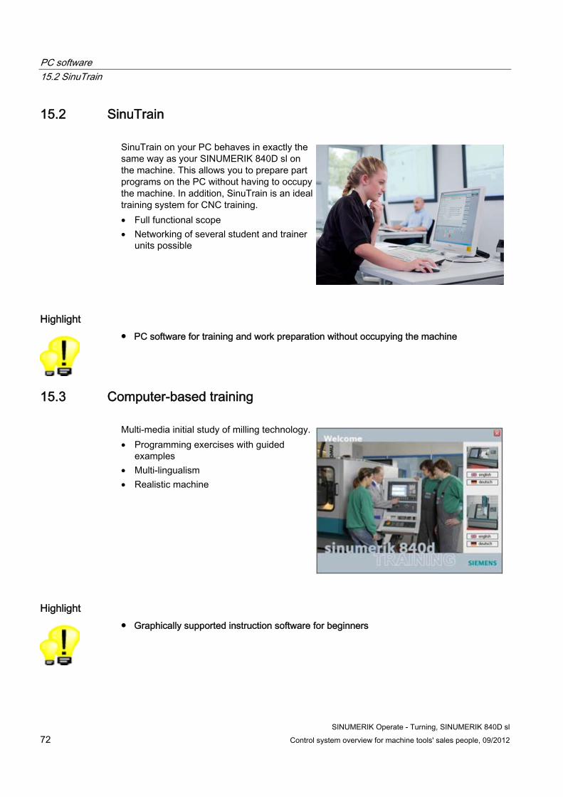
15.2 SinuTrain SinuTrain on your PC behaves in exactly the same way as your SINUMERIK 840D sl on the machine. This allows you to prepare part programs on the PC without having to occupy the machine. In addition, SinuTrain is an ideal training system for CNC training. • Full functional scope • Networking of several student and trainer
units possible
Highlight ● PC software for training and work preparation without occupying the machine
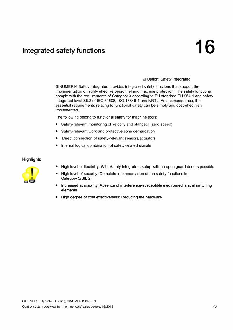
15.3 Computer-based training Multi-media initial study of milling technology. • Programming exercises with guided
examples • Multi-lingualism • Realistic machine
Highlight ● Graphically supported instruction software for beginners
SINUMERIK Operate - Turning, SINUMERIK 840D sl Control system overview for machine tools' sales people, 09/2012 73
Integrated safety functions 16
☑ Option: Safety Integrated
SINUMERIK Safety Integrated provides integrated safety functions that support the implementation of highly effective personnel and machine protection. The safety functions comply with the requirements of Category 3 according to EU standard EN 954-1 and safety integrated level SIL2 of IEC 61508, ISO 13849-1 and NRTL. As a consequence, the essential requirements relating to functional safety can be simply and cost-effectively implemented.
The following belong to functional safety for machine tools:
● Safety-relevant monitoring of velocity and standstill (zero speed)
● Safety-relevant work and protective zone demarcation
● Direct connection of safety-relevant sensors/actuators
● Internal logical combination of safety-related signals
Highlights ● High level of flexibility: With Safety Integrated, setup with an open guard door is possible
● High level of security: Complete implementation of the safety functions in Category 3/SIL 2
● Increased availability: Absence of interference-susceptible electromechanical switching elements
● High degree of cost effectiveness: Reducing the hardware
Integrated safety functions
SINUMERIK Operate - Turning, SINUMERIK 840D sl 74 Control system overview for machine tools' sales people, 09/2012
SINUMERIK Operate - Turning, SINUMERIK 840D sl Control system overview for machine tools' sales people, 09/2012 75
Option list for the SINUMERIK package 17
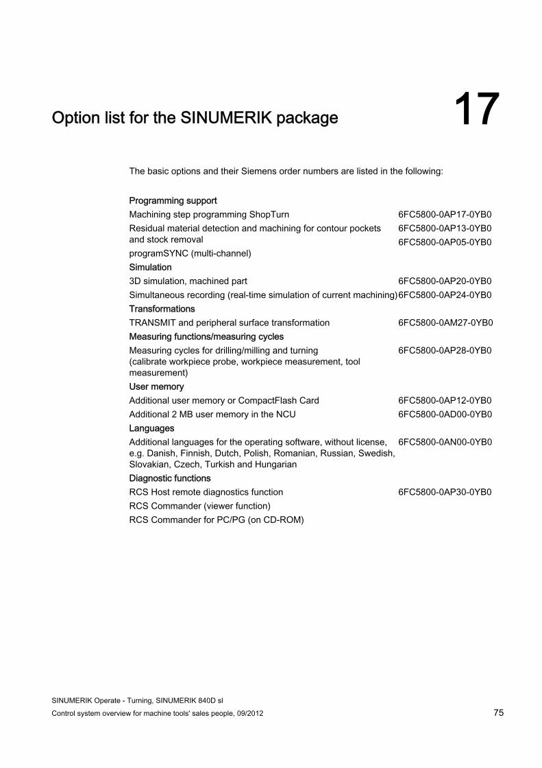
The basic options and their Siemens order numbers are listed in the following:
Programming support Machining step programming ShopTurn Residual material detection and machining for contour pockets and stock removal programSYNC (multi-channel)
6FC5800-0AP17-0YB0 6FC5800-0AP13-0YB0 6FC5800-0AP05-0YB0
Simulation 3D simulation, machined part Simultaneous recording (real-time simulation of current machining)
6FC5800-0AP20-0YB0 6FC5800-0AP24-0YB0
Transformations TRANSMIT and peripheral surface transformation
6FC5800-0AM27-0YB0
Measuring functions/measuring cycles Measuring cycles for drilling/milling and turning (calibrate workpiece probe, workpiece measurement, tool measurement)
6FC5800-0AP28-0YB0
User memory Additional user memory or CompactFlash Card Additional 2 MB user memory in the NCU
6FC5800-0AP12-0YB0 6FC5800-0AD00-0YB0
Languages Additional languages for the operating software, without license, e.g. Danish, Finnish, Dutch, Polish, Romanian, Russian, Swedish, Slovakian, Czech, Turkish and Hungarian
6FC5800-0AN00-0YB0
Diagnostic functions RCS Host remote diagnostics function RCS Commander (viewer function) RCS Commander for PC/PG (on CD-ROM)
6FC5800-0AP30-0YB0
Option list for the SINUMERIK package
SINUMERIK Operate - Turning, SINUMERIK 840D sl 76 Control system overview for machine tools' sales people, 09/2012
SINUMERIK Operate - Turning, SINUMERIK 840D sl Control system overview for machine tools' sales people, 09/2012 77
Summary of unique features 18
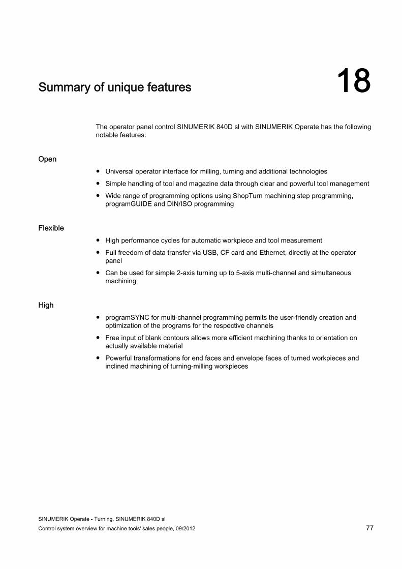
The operator panel control SINUMERIK 840D sl with SINUMERIK Operate has the following notable features:
Open ● Universal operator interface for milling, turning and additional technologies
● Simple handling of tool and magazine data through clear and powerful tool management
● Wide range of programming options using ShopTurn machining step programming, programGUIDE and DIN/ISO programming
Flexible ● High performance cycles for automatic workpiece and tool measurement
● Full freedom of data transfer via USB, CF card and Ethernet, directly at the operator panel
● Can be used for simple 2-axis turning up to 5-axis multi-channel and simultaneous machining
High ● programSYNC for multi-channel programming permits the user-friendly creation and
optimization of the programs for the respective channels
● Free input of blank contours allows more efficient machining thanks to orientation on actually available material
● Powerful transformations for end faces and envelope faces of turned workpieces and inclined machining of turning-milling workpieces
Summary of unique features
SINUMERIK Operate - Turning, SINUMERIK 840D sl 78 Control system overview for machine tools' sales people, 09/2012
SINUMERIK Operate - Turning, SINUMERIK 840D sl Control system overview for machine tools' sales people, 09/2012 79
Index
8 80bit NANO FP accuracy, 43
A Animated Elements, 37
B Basic block display, 40 Block search, 39
C CAD Reader, 71 CNC memory, 29 CNC technology cycles
programGuide, 57 ShopTurn, 57
CompactFlash Card, 29 Contour stock removal cycle, 58
D Data transfer
RCS Commander, 34 Detection of residual material when milling, 62 DIN/ISO language, 49 DIN/ISO programming, 49 DXF converter, 71
E Engraving cycle, 59
F Feedforward control, 45 Flashcard, 29 Front end machining, 65
G G code editor, 48
H Hard disk, 30
I In-process measurement, 63
M Machine spectrum, 10 Measure tool, 22 Monitoring of tool life and workpiece count, 26 Multi-channel machining
Blocks, 69 Job list, 68 Machine basic screen, 67 programSYNC, 68 Simulation, 70 Wait marks, 69
O Online Help, 38 Operator panel fronts, 12 Operator Panels, 12 Ordering data, 75
P PC software, 71 Peripheral surface machining, 66 Program control, 41 Program editing, 41 Program editor, 48 Program manager, 33 Program test, 41
Index
SINUMERIK Operate - Turning, SINUMERIK 840D sl 80 Control system overview for machine tools' sales people, 09/2012
R RCS Commander, 34 Reduced rapid traverse, 41 Replacement tools, 27 Repositioning to the contour, 41 Residual material detection during turning, 61
S Safety Functions, 73 Safety Integrated, 73 Sequence editor, 51 Simulation
2D, 55 3D, 56 Processing time, 56
Simultaneous recording, 42 Single block, 41 SINUMERIK 840D sl, 11 SinuTrain, 72 Stock removal cycle, 21
T Tool management, 25 TRACYL, 66 TRANSMIT, 65 TSM universal cycle, 19
U Unique selling points, 77 User memory, 29
V Velocity control, 44
W Work offsets, 24