siphon feed sandblaster - …€¦ · thank you for purchasing this clarke siphon feed sandblaster....
TRANSCRIPT
SIPHON FEED SANDBLASTERMODEL NO: CSB10
PART NO: 7640117
OPERATION & MAINTENANCEINSTRUCTIONS
LS0513

INTRODUCTION
Thank you for purchasing this Clarke siphon feed sandblaster.
Before you try to use this product, read this manual and follow the instructions carefully. In doing so you will ensure your safety and the safety of others around you. You can also look forward to a purchase that gives you long and satisfactory service.
GUARANTEE
This product is guaranteed against faulty manufacture for a period of 12 months from the date of purchase. Please keep your receipt which will be required as proof of purchase.
This guarantee is invalid if the product is found to have been abused or tampered with in any way, or not used for the purpose for which it was intended.
Faulty goods should be returned to their place of purchase, no product can be returned to us without prior permission.
This guarantee does not effect your statutory rights.
CONSUMABLES
Please be aware that certain parts of this sandblaster will wear, requiring replacement and that these parts may not be covered by your guarantee.
The wear on certain parts depends on the abrasiveness of the materials used.
Replacement parts are available from your nearest Clarke International dealer.
2

GENERAL SAFETY RULES
1. Read this instruction manual before connecting this device to the compressor.
2. Do not use any silica based abrasives with this sandblaster. Silica based abrasives have been linked to severe respiratory disease. Always use recommended abrasives. Abrasives used in this sandblaster may be covered by COSHH Regulations.
3. Safety glasses, hood, long-sleeve shirt, gloves and a NIOSH/MSHA approved respirator must be worn during operation and clean up.
4. During operation, do not expose the hands or skin directly in the line of the Sandblasting Gun nozzle.
5. After assembly, inspect to make sure all components seal properly.
6. Everyone in the blasting area must also wear protective gear.
7. Check hoses and air lines for weak or worn condition before each use.Make sure all connections are secure before use.
8. Products used in this unit may be covered by COSHH Regulations.
9. ALWAYS make sure there is adequate ventilation. Do not spray in confined or enclosed areas.
10. ALWAYS disconnect the gun from the air supply when it is not in use, and before any disassembly.
11. ALWAYS thoroughly clean the gun after use. See ‘Maintenance’
12. ALWAYS turn OFF the air supply at the compressor outlet, and expel all air from the air hose and gun, BEFORE disconnecting the Sandblasting Gun from the air hose.
Warning: Compressed air can be dangerous. Ensure that you are thoroughly familiar with all precautions relating to the use of compressors and compressed air supply.
Warning: Disconnect the abrasive blaster from the air supply before changing accessories or attempting to install, service, relocate or perform any maintenance.
Warning: Do not point the abrasive blaster gun at anyone or objects other than the intended work object.
3
13. ALWAYS use appropriate air hoses and couplings and ensure that they are in good condition. If any parts are worn or damaged, they should be replaced immediately.
14. ALWAYS hold the tool firmly and maintain good balance.
15. ALWAYS ensure hose couplings are secure before use.
16. NEVER carry the gun by the hose. Keep hoses away from heat, oil and sharp edges.
17. NEVER use wet or even damp grit. Ensure the grit is completely dry,
18. Never direct the Grit Spray at people or animals. In the case of injury, seek expert medical advice immediately.
19. NEVER allow children to use or play with this appliance.
4
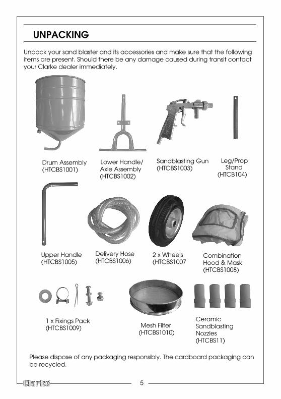
UNPACKING
Unpack your sand blaster and its accessories and make sure that the following items are present. Should there be any damage caused during transit contact your Clarke dealer immediately.
Drum Assembly Lower Handle/
2 x WheelsUpper Handle
Sandblasting Gun
Delivery Hose
1 x Fixings Pack
Axle AssemblyLeg/Prop
Stand
Combination
Mesh FilterCeramic
Hood & Mask
Sandblasting Nozzles
(HTCBS1001)(HTCBS1002)
(HTCBS1003)(HTCB104)
(HTCBS1005) (HTCBS1006) (HTCBS1007(HTCBS1008)
(HTCBS1009)(HTCBS1010)
(HTCBS11)
Please dispose of any packaging responsibly. The cardboard packaging can be recycled.
5

ASSEMBLY
1.
Split Pin
Wheel
WasherWasher
Split PinSplit Pin
Insert the split pin into the lower handle/axle assembly as shown on the right.
2. Slide a washer, the wheel, and another washer onto the axle.
3. Secure in place using a second split pin.
4.
Leg/Prop Stand
Fit the leg/prop stand to the drum and secure in place using 1 long bolt, 1 washer and 1 nut.
5. Attach the lower handle/axle assembly to the drum and use 2 short bolts, 2 washers and 2 nuts to secure into place.
6
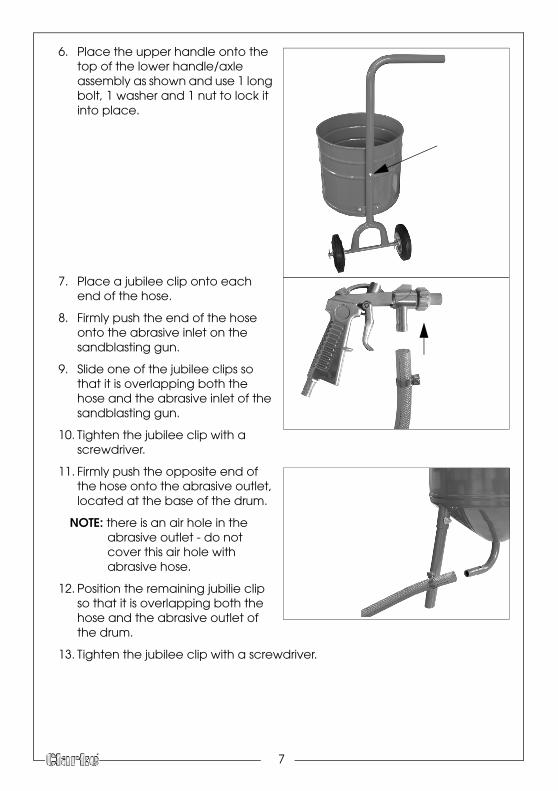
6. Place the upper handle onto the top of the lower handle/axle assembly as shown and use 1 long bolt, 1 washer and 1 nut to lock it into place.
7. Place a jubilee clip onto each end of the hose.
8. Firmly push the end of the hose onto the abrasive inlet on the sandblasting gun.
9. Slide one of the jubilee clips so that it is overlapping both the hose and the abrasive inlet of the sandblasting gun.
10. Tighten the jubilee clip with a screwdriver.
11. Firmly push the opposite end of the hose onto the abrasive outlet, located at the base of the drum.
NOTE: there is an air hole in the abrasive outlet - do not cover this air hole with abrasive hose.
12. Position the remaining jubilie clip so that it is overlapping both the hose and the abrasive outlet of the drum.
13. Tighten the jubilee clip with a screwdriver.
7

OPERATION
USING YOUR SANDBLASTERConnect your sandblasting gun to a compressor (minimum 3hp) via the 3/8” hose adaptor located at the base of the handle.
Set the air pressure on your air compressor to 100 -150 psi.
1. Connect a air hose (sold separately) between your air compressor, and the hose fitting on the sandblasting gun.
2. Make sure air hole located on the base of the abrasive tank is not covered.
3. Place the mesh filter on top of the drum and pour the blasting medium through the filter into the drum (max 50 lbs)
4. Start compressor.
5. Check for leaks along all hoses and fittings. if leaks are found, turn off the air compressor, disconnect the hose and repair immediately.
6. Point the sandblasting gun in a safe direction away from people, pets or anything around you that may be damaged by direct or indirect abrasive spray.
7. Press and hold the sandblasting gun trigger until abrasive media is flowing through the nozzle.
TO STOP BLASTING1. Release the trigger on the sandblasting gun.
8
MAINTENANCE
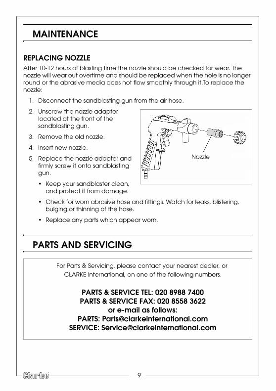
REPLACING NOZZLEAfter 10-12 hours of blasting time the nozzle should be checked for wear. The nozzle will wear out overtime and should be replaced when the hole is no longer round or the abrasive media does not flow smoothly through it.To replace the nozzle:
1. Disconnect the sandblasting gun from the air hose.
2.
Nozzle
Unscrew the nozzle adapter, located at the front of the sandblasting gun.
3. Remove the old nozzle.
4. Insert new nozzle.
5. Replace the nozzle adapter and firmly screw it onto sandblasting gun.
• Keep your sandblaster clean, and protect it from damage.
• Check for worn abrasive hose and fittings. Watch for leaks, blistering, bulging or thinning of the hose.
• Replace any parts which appear worn.
PARTS AND SERVICING
For Parts & Servicing, please contact your nearest dealer, or
CLARKE International, on one of the following numbers.
PARTS & SERVICE TEL: 020 8988 7400PARTS & SERVICE FAX: 020 8558 3622
or e-mail as follows:PARTS: [email protected]
SERVICE: [email protected]
9

10
SPECIFICATIONS
CSB10
Sand Grade Type Up to 60 Grit (Clarke AOP60)
Abrasive Material Aluminium Oxide, Garnet Powder, Glass Bead
Drum Capacity: (gallons) 3.7 UK
Sand Capacity: (kg/lbs) 22.6/50
Operating Pressure: (psi) 100-150
Flow Rate Req. (cfm) 10-16
Compressor Size Hp (Minimum) 3
Gun Inlet Size: 3/8” hose adaptor fitted
Air Inlet Hose Diameter: 3/8” (10mm)
Nozzle Sizes: (mm) 4, 5, 6, 7 (Ceramic)
Dimensions (Length x Width x Height) 744 mm x 279 mm x 378 mm
Weight 4.4 Kg
11
NOTES