siphonic roof drains - engineered plumbing & drainage … - siphonic roof drains... · siphonic...
TRANSCRIPT
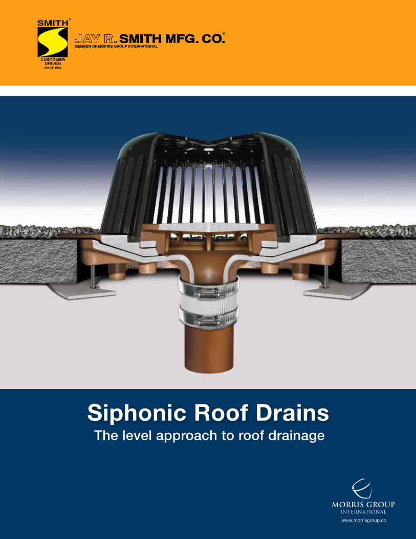
Siphonic Roof Drains
www.morrisgroup.co
MORRIS GROUPINTERNATIONAL
The level approach to roof drainage
Table of Contents
Introduction 1
Overview 1
Siphonic Roof Drain Anatomy 1
The Siphon Principle 2
Main Principles of Traditional and Siphonic Drainage 2-3
The Self-Priming Process in a Siphonic System 4
Why You Should Consider a Siphonic Roof Drain System 5
Product Selection 6
Installation and Application 7
Siphonic Roof Drainage for Building Retrofits 7
Specifier’s Guide 8
Codes and Standards 9
Case Study - Shopping Mall 10
Case Studies - IKEA Home Furnishings Stores 11
Cost Savings Application Examples 12
The Many Benefits of Using Siphonic 13
Siphonic Roof Drains
www.jrsmith.com Jay R. Smith Mfg. Co. 800.467.6484
IntroductionJay R. Smith Mfg. Co. performed prototype development and testing for several years, achieving tested and proven siphonic roof drainage products and being the first U.S. manufacturer to offer these products. • Jay R. Smith Mfg. Co.’s siphonic roof drains promote full-bore flow within engineered siphonic roof drainage piping systems.• Fully tested and certified in accordance with ANSI/ ASTM A112.6.9 “Siphonic Roof Drains” and representing the first-line of specified roof drains complying with this American National Standard. Also, meets all requirements of the ASPE Standard 45, Siphonic Roof Drainage.• Cast of solid ASTM 48 grey iron and utilizing the same set of accessories already familiar to the plumbing engineer and installer, thus making specification and installation as easy as traditional roof drains.• The castings contain mainly recycled metal content making the products a part of a sustainable consumer cycle. • The low-profile nature of the baffle component of competitive siphonic roof drains can make them prone to quicker blockage
by debris. Smith’s siphonic roof drains have a polyethylene dome strainer to help protect the baffle from debris accumulation and allow for the passage of water even if debris collects around the strainer base. This design makes our siphonic roof drains behave in the same manner as traditional roof drains in all types of rainfall and roof conditions.
OverviewIn a siphonic roof drainage system, Smith’s specially engineered and tested roof drain baffle allows and sustains negative atmospheric pressure in the connected piping and inhibits the admission of air into the piping system hence sustaining full-bore flow, higher flow volumes and velocities. The hydraulic balance in a siphonicroof drainage system is achieved by an engineer employing hydraulic calculations to ensure that the piping system fills up automatically in cases of moderate to heavy precipitation. The resulting full-bore or siphonic action allows for the installation of horizontal, i.e., level, drainage manifold piping serving multiple roof drains. Siphonic roof drainage systems are powered by and discharge to grade by means of a vertical stack into the point of discharge through the influence of gravity, making them true gravity systems.
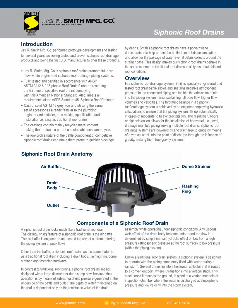
Dome StrainerAir Baffle
Flashing Ring
Drain Body
Outlet
Siphonic Roof Drain Anatomy
A siphonic roof drain looks much like a traditional roof drain. The distinguishing feature of a siphonic roof drain is the air baffle. This air baffle is engineered and tested to prevent air from entering the piping system at peak flows.
Other than the baffle, a siphonic roof drain has the same features as a traditional roof drain including a drain body, flashing ring, dome strainer, and fastening hardware.
In contrast to traditional roof drains, siphonic roof drains are not designed with a large diameter or deep sump bowl because their operation is by means of sub-atmospheric pressure generated at the underside of the baffle and outlet. The depth of water maintained on the roof is dependent only on the resistance value of the drain
assembly while operating under siphonic conditions. Any viscous weir effect of the drain body becomes minor and the flow is determined by simple inertial hydraulic effect of flow from a high pressure (atmospheric pressure at the roof surface) to low pressure (within the piping system). Unlike a traditional roof drain system, a siphonic system is designed to operate with the piping completely filled with water during a rainstorm. Several drains tie into a horizontal collector that is routed to a convenient point where it transitions into a vertical stack. This stack, once it reaches the ground, is piped to a vented manhole or inspection-chamber where the water is discharged at atmospheric pressure and low velocity into the storm system.
1
Components of a Siphonic Roof Drain
Siphonic Roof Drains
www.jrsmith.com Jay R. Smith Mfg. Co. 800.467.6484
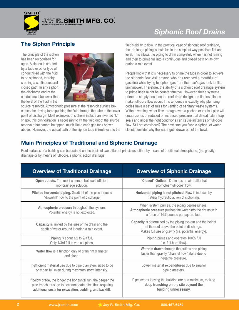
The Siphon Principle
The principle of the siphonhas been recognized forages. A siphon is createdby a tube or other type ofconduit filled with the fluidto be siphoned, therebycreating a continuous andclosed path. In any siphon,the discharge end of theconduit must be lower thanthe level of the fluid in thesource reservoir. Atmospheric pressure at the reservoir surface be-comes the driving force pushing the fluid through the tube to the lower point of discharge. Most examples of siphons include an inverted “U” shape, this configuration is necessary to lift the fluid out of the source reservoir that cannot be tipped, much like a car’s gas tank shown above. However, the actual path of the siphon tube is irrelevant to the
fluid’s ability to flow. In the practical case of siphonic roof drainage, the drainage piping is installed in the simplest way possible: flat and level. This allows the piping to drain completely when it is not raining and then to prime full into a continuous and closed path on its own during a rain event.
People know that it is necessary to prime the tube in order to achieve the siphonic flow. Ask anyone who has received a mouthful of gasoline while trying to siphon gas from their car’s gas tank to fill a lawnmower. Therefore, the ability of a siphonic roof drainage system to prime itself might be counterintuitive. However, these systems prime up simply because the roof drain design and flat installation make full-bore flow occur. This tendency is exactly why plumbing codes have a set of rules for venting of sanitary waste systems. Without venting, water flow through even a pitched or vertical pipe will create zones of reduced or increased pressure that defeat fixture trap seals and under the right conditions can cause instances of full-bore flow. Still not convinced? The next time you flush a siphon-jet water closet, consider why the water gets drawn out of the bowl.
Main Principles of Traditional and Siphonic Drainage Roof surfaces of a building can be drained on the basis of two different principles, either by means of traditional atmospheric, (i.e. gravity)drainage or by means of full-bore, siphonic action drainage.
Overview of Traditional Drainage Overview of Siphonic Drainage
Open outlets. The most common but least efficientroof drainage solution.
“Closed” Outlets. Drain has an air baffle thatpromotes “full-bore” flow.
Pitched horizontal piping. Gradient of the pipe induces “downhill” flow to the point of discharge.
Horizontal piping is not pitched. Flow is induced bynatural hydraulic action of siphoning.
Atmospheric pressure throughout the system.Potential energy is not exploited.
When system primes, the piping depressurizes.Atmospheric pressure pushes the water into the drains with
a force of 14.7 pounds per square foot.
Capacity is limited by the size of the drain and thedepth of water around it during a rain event.
Capacity is determined by the piping system and the height of the roof above the point of discharge.
Makes full use of gravity (i.e. potential energy).Piping is about 1/2 to 2/3 full.Only 1/3rd full in vertical pipes.
Piping primes and operates 100% full (i.e. full-bore flow).
Water flow is a function only of drain rim diameterand slope.
Water is drawn through the outlets and piping faster than gravity “channel flow” alone due to
negative pressure.
Inefficient material use due to pipe diameters sized to be only part full even during maximum storm intensity.
Lower material expenditures due to smaller pipe diameters.
If below grade, the longer the horizontal run, the deeper the pipe trench must go to accommodate pitch thus requiring
additional costs for excavation, bedding, and backfill.
Pipe inverts leaving the building are at a minimum, making deep trenching on the site beyond the
building unnecessary.
2
Siphonic Roof Drains
www.jrsmith.com Jay R. Smith Mfg. Co. 800.467.6484
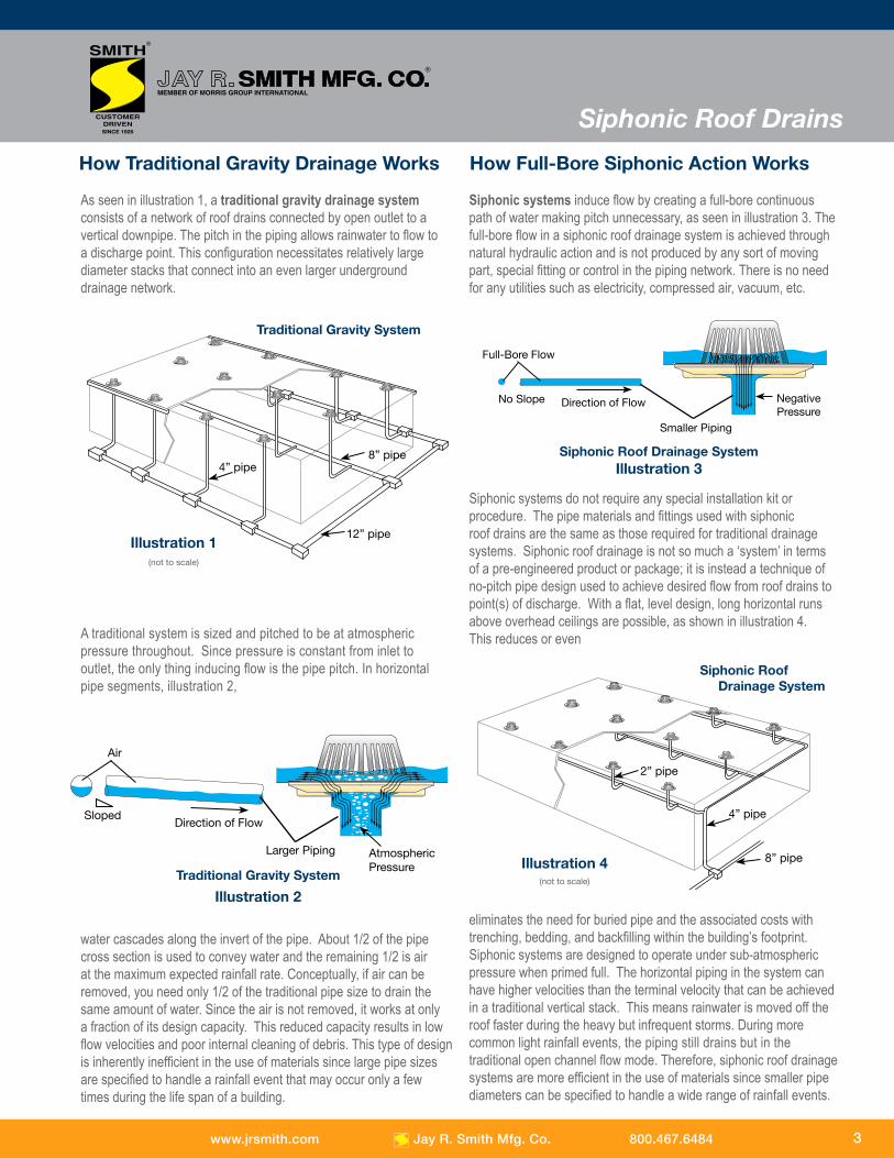
A traditional system is sized and pitched to be at atmospheric pressure throughout. Since pressure is constant from inlet to outlet, the only thing inducing flow is the pipe pitch. In horizontal pipe segments, illustration 2,
water cascades along the invert of the pipe. About 1/2 of the pipe cross section is used to convey water and the remaining 1/2 is air at the maximum expected rainfall rate. Conceptually, if air can be removed, you need only 1/2 of the traditional pipe size to drain the same amount of water. Since the air is not removed, it works at only a fraction of its design capacity. This reduced capacity results in low flow velocities and poor internal cleaning of debris. This type of design is inherently inefficient in the use of materials since large pipe sizes are specified to handle a rainfall event that may occur only a few times during the life span of a building.
Siphonic systems induce flow by creating a full-bore continuous path of water making pitch unnecessary, as seen in illustration 3. The full-bore flow in a siphonic roof drainage system is achieved through natural hydraulic action and is not produced by any sort of moving part, special fitting or control in the piping network. There is no need for any utilities such as electricity, compressed air, vacuum, etc.
Siphonic systems do not require any special installation kit or procedure. The pipe materials and fittings used with siphonic roof drains are the same as those required for traditional drainage systems. Siphonic roof drainage is not so much a ‘system’ in terms of a pre-engineered product or package; it is instead a technique of no-pitch pipe design used to achieve desired flow from roof drains to point(s) of discharge. With a flat, level design, long horizontal runs above overhead ceilings are possible, as shown in illustration 4. This reduces or even
eliminates the need for buried pipe and the associated costs with trenching, bedding, and backfilling within the building’s footprint. Siphonic systems are designed to operate under sub-atmospheric pressure when primed full. The horizontal piping in the system can have higher velocities than the terminal velocity that can be achieved in a traditional vertical stack. This means rainwater is moved off the roof faster during the heavy but infrequent storms. During more common light rainfall events, the piping still drains but in the traditional open channel flow mode. Therefore, siphonic roof drainage systems are more efficient in the use of materials since smaller pipe diameters can be specified to handle a wide range of rainfall events.
How Full-Bore Siphonic Action WorksHow Traditional Gravity Drainage Works
As seen in illustration 1, a traditional gravity drainage system consists of a network of roof drains connected by open outlet to a vertical downpipe. The pitch in the piping allows rainwater to flow to a discharge point. This configuration necessitates relatively large diameter stacks that connect into an even larger underground drainage network.
Illustration 1(not to scale)
4” pipe
12” pipe
8” pipe
Traditional Gravity System
Illustration 4(not to scale)
8” pipe
4” pipe
2” pipe
Siphonic Roof Drainage System
Illustration 2
Air
SlopedDirection of Flow
Larger Piping AtmosphericPressure
Traditional Gravity System
Full-Bore Flow
No Slope Direction of Flow NegativePressure
Smaller Piping
Illustration 3Siphonic Roof Drainage System
3
Siphonic Roof Drains
www.jrsmith.com Jay R. Smith Mfg. Co. 800.467.6484
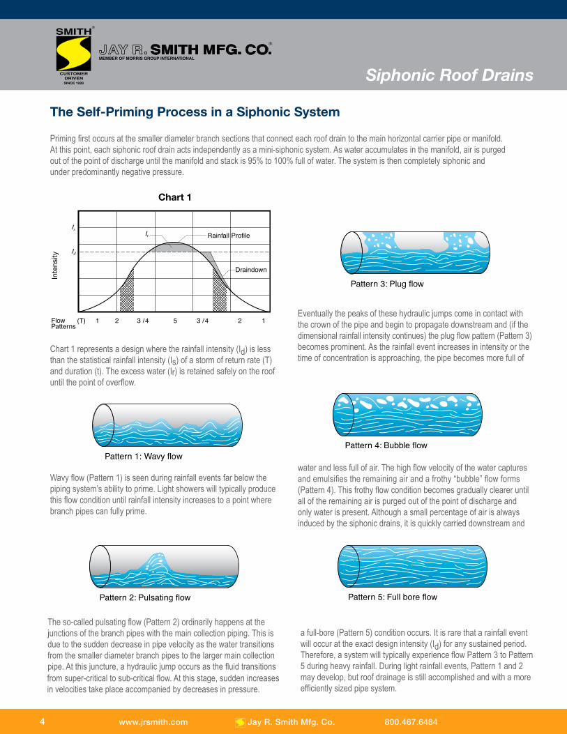
Priming first occurs at the smaller diameter branch sections that connect each roof drain to the main horizontal carrier pipe or manifold. At this point, each siphonic roof drain acts independently as a mini-siphonic system. As water accumulates in the manifold, air is purged out of the point of discharge until the manifold and stack is 95% to 100% full of water. The system is then completely siphonic and under predominantly negative pressure.
The Self-Priming Process in a Siphonic System
Chart 1 represents a design where the rainfall intensity (Id) is less than the statistical rainfall intensity (Is) of a storm of return rate (T) and duration (t). The excess water (Ir) is retained safely on the roof until the point of overflow.
Wavy flow (Pattern 1) is seen during rainfall events far below the piping system’s ability to prime. Light showers will typically produce this flow condition until rainfall intensity increases to a point where branch pipes can fully prime.
from super-critical to sub-critical flow. At this stage, sudden increases in velocities take place accompanied by decreases in pressure.
Inte
nsity
Eventually the peaks of these hydraulic jumps come in contact with the crown of the pipe and begin to propagate downstream and (if the dimensional rainfall intensity continues) the plug flow pattern (Pattern 3) becomes prominent. As the rainfall event increases in intensity or the time of concentration is approaching, the pipe becomes more full of
water and less full of air. The high flow velocity of the water captures and emulsifies the remaining air and a frothy “bubble” flow forms (Pattern 4). This frothy flow condition becomes gradually clearer until all of the remaining air is purged out of the point of discharge and only water is present. Although a small percentage of air is always induced by the siphonic drains, it is quickly carried downstream and
a full-bore (Pattern 5) condition occurs. It is rare that a rainfall event will occur at the exact design intensity (Id) for any sustained period. Therefore, a system will typically experience flow Pattern 3 to Pattern 5 during heavy rainfall. During light rainfall events, Pattern 1 and 2 may develop, but roof drainage is still accomplished and with a more efficiently sized pipe system.
Chart 1
The so-called pulsating flow (Pattern 2) ordinarily happens at the junctions of the branch pipes with the main collection piping. This is due to the sudden decrease in pipe velocity as the water transitions from the smaller diameter branch pipes to the larger main collection pipe. At this juncture, a hydraulic jump occurs as the fluid transitions
4
Siphonic Roof Drains
www.jrsmith.com Jay R. Smith Mfg. Co. 800.467.6484
Why You Should Consider a Siphonic Roof Drainage System
These benefits enable significant savings in terms of time and money. Large roof construction similar to those found on factories, warehouses, airports, convention centers, stadiums and “big box” retailers will realize the benefits of siphonic roof drainage and favor this type of roof drainage system. However, all buildings regardless of size or height can realize the economic and technical benefits offered by siphonic roof drainage.
Smaller pipe diameters with a siphonic system can be used, reducing material costs.Full-bore flow within the piping reduces pipe diameter as compared to open-channel, traditional gravity flow. The smaller pipe size equates to savings in material. For example, while a traditionally designed system calls for an eight (8”) inch pipe, a siphonic system of equal drainage capacity may need only a four (4”) inch or six (6”) inch pipe to drain the same quantity of water.
Siphonic action permits level pipe installations, allowing fewer vertical stacks, saving ground work and building costs.
Traditional systems are designed to be atmospheric throughout and rely on pipe gradient or pitch to induce flow to the point of discharge. This pitch necessitates the pipe elevation to become increasingly lower as it runs laterally. Full-bore flow is achieved independently of pipe gradient in a siphonic system. The piping can be installed flat like any other mechanical system such as sprinklers and it simplifies coordination with other building elements. With siphonic piping being horizontal, the building height may be reduced by 3 to 4 feet, saving on construction costs.
Driving head of the siphonic system is up to 100 times that of a traditional system (i.e. height of building vs. depth on roof).
Siphonic roof drainage systems make full use of a building’s roof height to drive the drainage capacity. The resulting higher operating velocities (3 ft/sec up to 30 ft/sec) of a siphonic system further reduce pipe size and promote self-cleaning of debris.
In a siphonic system, below-slab installation costs are minimized, thus reducing excavation, backfill costs and exterior underground piping.
Level installation allows for longer lateral runs overhead thereby reducing or eliminating pipe installed below slab and the associated costs of excavation, bedding and backfill. If overhead, traditional drainage pipe has to quickly drop vertically to avoid a conflict with the ceiling, structural elements or HVAC systems. If below grade, the longer the horizontal run, the deeper the pipe trench must go to accommodate pitch. Siphonic systems reduce or eliminate these issues. This means there are lower site preparation costs.
Within a siphonic roof drain system, stack andhorizontal pipe locations are highly flexible.
Level installation and freedom of placement of vertical stacks reduces buried pipe depths and the associated costs of trenching, bedding, shoring, and dewatering. The flexibility of stack placement also facilitates on-site rainwater harvesting by allowing flexibility for cistern locations either below or above ground.
A siphonic system allows for maximum use ofopen space without intrusion of drainage piping.
Smaller diameter piping conforming to structural and architectural lines presents a less intrusive presence in an open area. Level installation and freedom of placement of vertical stacks reduces the size of exterior storm sewer infrastructure. The point of discharge for the roof can typically be concentrated to one corner rather than out of the building at several points.
www.jrsmith.com Jay R. Smith Mfg. Co. 800.467.6484 5
Siphonic Roof Drains
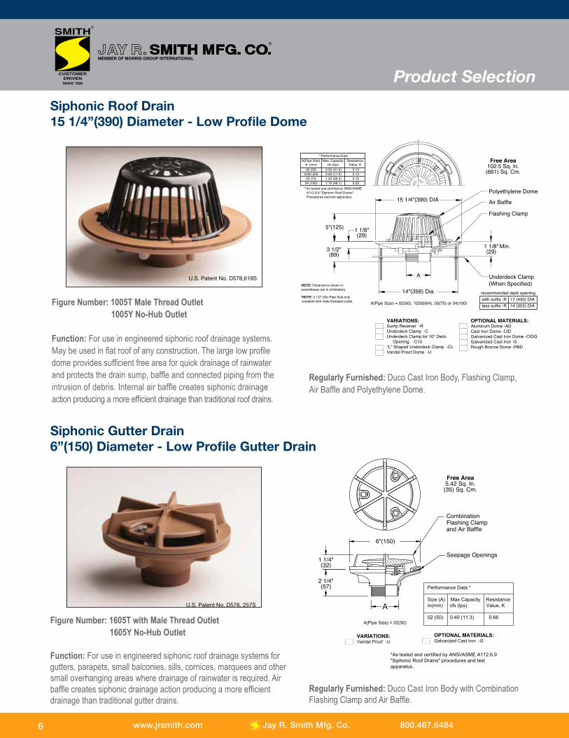
Siphonic Gutter Drain6”(150) Diameter - Low Profile Gutter Drain
Figure Number: 1605T with Male Thread Outlet 1605Y No-Hub Outlet
Function: For use in engineered siphonic roof drainage systems for gutters, parapets, small balconies, sills, cornices, marquees and other small overhanging areas where drainage of rainwater is required. Air baffle creates siphonic drainage action producing a more efficient drainage than traditional gutter drains.
VARIATIONS:Sump Receiver -RUnderdeck Clamp -CUnderdeck Clamp for 10" Deck Opening -C10"L" Shaped Underdeck Clamp -CLVandal Proof Dome -U
OPTIONAL MATERIALS:Aluminum Dome -ADCast Iron Dome -CIDGalvanized Cast Iron Dome -CIDGGalvanized Cast Iron -GRough Bronze Dome -RBD
A
Polyethylene Dome
Air Baffle
Underdeck Clamp (When Specified)
Flashing Clamp
15 1/4"(390) DIA
5"(125)
14"(356) Dia.
1 1/8"(29)
1 1/8"(29)3 1/2"
(89)
Free Area102.5 Sq. In.(661) Sq. Cm.
NOTE: Dimensions shown inparentheses are in millimeters.
*NOTE: 2 1/2" (64) Pipe Size only available with male threaded outlet. A(Pipe Size) = 02(50), *0250(64), 03(75) or 04(100)
recommended deck openingwith suffix -R 17 (430) DIAless suffix -R 14 (355) DIA
**Performance Data
**As tested and certified by ANSI/ASME A112.6.9 "Siphonic Roof Drains" Procedures and test apparatus.
A(Pipe Size)in. (mm)
Max. Capacitycfs (lps)
ResistanceValue, K
02 (50)0250 (64)03 (75)04 (100)
0.50 (41.2)0.60 (17.0)1.40 (39.5)1.70 (48.1)
0.130.130.160.23
Min.
A(Pipe Size) = 02(50)
A
Combination Flashing Clamp and Air Baffle
Performance Data *
Size (A) Max Capacity Resistancein(mm) cfs (lps) Value, K
02 (50) 0.40 (11.3) 0.66
VARIATIONS:Vandal Proof -U
OPTIONAL MATERIALS:Galvanized Cast Iron -G
*As tested and certified by ANSI/ASME A112.6.9 "Siphonic Roof Drains" procedures and test apparatus.
6"(150)
1 1/4"(32)
2 1/4"(57)
Seepage Openings
Free Area5.42 Sq. In.(35) Sq. Cm.
Figure Number: 1005T Male Thread Outlet 1005Y No-Hub Outlet
Function: For use in engineered siphonic roof drainage systems. May be used in flat roof of any construction. The large low profile dome provides sufficient free area for quick drainage of rainwater and protects the drain sump, baffle and connected piping from the intrusion of debris. Internal air baffle creates siphonic drainage action producing a more efficient drainage than traditional roof drains.
Regularly Furnished: Duco Cast Iron Body, Flashing Clamp, Air Baffle and Polyethylene Dome.
Regularly Furnished: Duco Cast Iron Body with Combination Flashing Clamp and Air Baffle.
Siphonic Roof Drain15 1/4”(390) Diameter - Low Profile Dome
Product Selection
U.S. Patent No. D578,619S
U.S. Patent No. D576, 257S
6 www.jrsmith.com Jay R. Smith Mfg. Co. 800.467.6484
Installation & Application
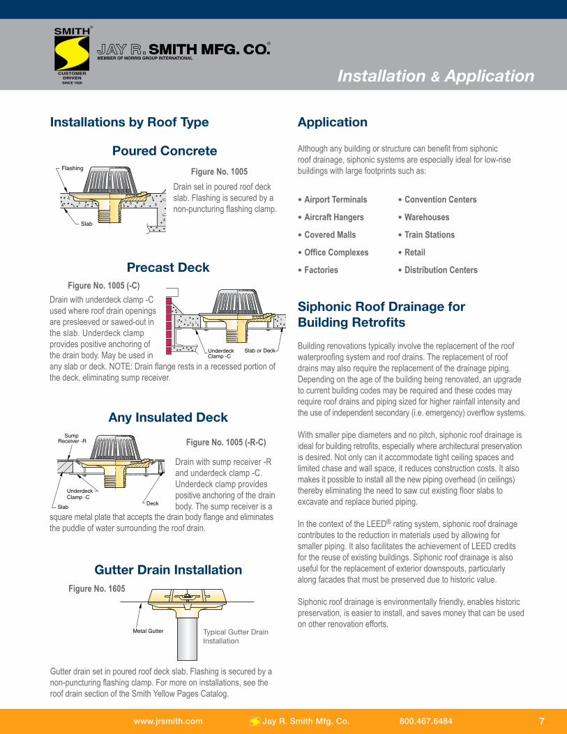
Installations by Roof Type
Flashing
Slab
UnderdeckClamp -C
Underdeck Clamp -C
Deck
Sump Receiver -R
Slab
Poured Concrete
Drain set in poured roof deck slab. Flashing is secured by a non-puncturing flashing clamp.
Drain with sump receiver -R and underdeck clamp -C. Underdeck clamp providespositive anchoring of the drain body. The sump receiver is a
Siphonic Roof Drainage for Building Retrofits
Building renovations typically involve the replacement of the roof waterproofing system and roof drains. The replacement of roof drains may also require the replacement of the drainage piping. Depending on the age of the building being renovated, an upgrade to current building codes may be required and these codes may require roof drains and piping sized for higher rainfall intensity and the use of independent secondary (i.e. emergency) overflow systems.
With smaller pipe diameters and no pitch, siphonic roof drainage is ideal for building retrofits, especially where architectural preservation is desired. Not only can it accommodate tight ceiling spaces and limited chase and wall space, it reduces construction costs. It also makes it possible to install all the new piping overhead (in ceilings) thereby eliminating the need to saw cut existing floor slabs to excavate and replace buried piping.
In the context of the LEED® rating system, siphonic roof drainage contributes to the reduction in materials used by allowing for smaller piping. It also facilitates the achievement of LEED credits for the reuse of existing buildings. Siphonic roof drainage is also useful for the replacement of exterior downspouts, particularly along facades that must be preserved due to historic value.
Siphonic roof drainage is environmentally friendly, enables historic preservation, is easier to install, and saves money that can be used on other renovation efforts.
Flashing
Slab
UnderdeckClamp -C
Underdeck Clamp -C
Deck
Sump Receiver -R
Slab
Although any building or structure can benefit from siphonicroof drainage, siphonic systems are especially ideal for low-rise buildings with large footprints such as:
• Airport Terminals • Convention Centers
• Aircraft Hangers • Warehouses
• Covered Malls • Train Stations
• Office Complexes • Retail
• Factories • Distribution Centers
Application
Figure No. 1005
Precast Deck
Drain with underdeck clamp -C used where roof drain openings are presleeved or sawed-out in the slab. Underdeck clamp provides positive anchoring ofthe drain body. May be used inany slab or deck. NOTE: Drain flange rests in a recessed portion of the deck, eliminating sump receiver.
Figure No. 1005 (-C)
Flashing
Slab
UnderdeckClamp -C
Underdeck Clamp -C
Deck
Sump Receiver -R
Slab
Any Insulated Deck
Figure No. 1005 (-R-C)
square metal plate that accepts the drain body flange and eliminatesthe puddle of water surrounding the roof drain.
Gutter Drain InstallationFigure No. 1605
Gutter drain set in poured roof deck slab. Flashing is secured by a non-puncturing flashing clamp. For more on installations, see the roof drain section of the Smith Yellow Pages Catalog.
Metal Gutter Typical Gutter Drain Installation
7www.jrsmith.com Jay R. Smith Mfg. Co. 800.467.6484
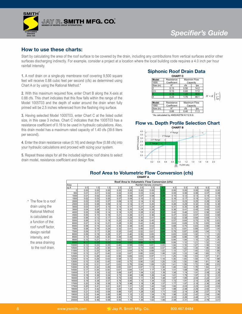
Flow vs. Depth Profile Selection ChartCHART B
Roof Area to Volumetric Flow Conversion (cfs)
Areasq ft 0.5 1.0 1.5 2.0 2.5 3.0 3.5 4.0 4.5 5.0 5.5 6.0 6.5
0 0.00 0.00 0.00 0.00 0.00 0.00 0.00 0.00 0.00 0.00 0.00 0.00 0.00500 0.01 0.01 0.02 0.02 0.03 0.03 0.04 0.05 0.05 0.06 0.06 0.07 0.08
1000 0.01 0.02 0.03 0.05 0.06 0.07 0.08 0.09 0.10 0.12 0.13 0.14 0.151500 0.02 0.03 0.05 0.07 0.09 0.10 0.12 0.14 0.16 0.17 0.19 0.21 0.232000 0.02 0.05 0.07 0.09 0.12 0.14 0.16 0.19 0.21 0.23 0.25 0.28 0.302500 0.03 0.06 0.09 0.12 0.14 0.17 0.20 0.23 0.26 0.29 0.32 0.35 0.383000 0.03 0.07 0.10 0.14 0.17 0.21 0.24 0.28 0.31 0.35 0.38 0.42 0.453500 0.04 0.08 0.12 0.16 0.20 0.24 0.28 0.32 0.36 0.41 0.45 0.49 0.534000 0.05 0.09 0.14 0.19 0.23 0.28 0.32 0.37 0.42 0.46 0.51 0.56 0.604500 0.05 0.10 0.16 0.21 0.26 0.31 0.36 0.42 0.47 0.52 0.57 0.63 0.685000 0.06 0.12 0.17 0.23 0.29 0.35 0.41 0.46 0.52 0.58 0.64 0.69 0.755500 0.06 0.13 0.19 0.25 0.32 0.38 0.45 0.51 0.57 0.64 0.70 0.76 0.836000 0.07 0.14 0.21 0.28 0.35 0.42 0.49 0.56 0.63 0.69 0.76 0.83 0.906500 0.08 0.15 0.23 0.30 0.38 0.45 0.53 0.60 0.68 0.75 0.83 0.90 0.987000 0.08 0.16 0.24 0.32 0.41 0.49 0.57 0.65 0.73 0.81 0.89 0.97 1.057500 0.09 0.17 0.26 0.35 0.43 0.52 0.61 0.69 0.78 0.87 0.95 1.04 1.138000 0.09 0.19 0.28 0.37 0.46 0.56 0.65 0.74 0.83 0.93 1.02 1.11 1.208500 0.10 0.20 0.30 0.39 0.49 0.59 0.69 0.79 0.89 0.98 1.08 1.18 1.289000 0.10 0.21 0.31 0.42 0.52 0.63 0.73 0.83 0.94 1.04 1.15 1.25 1.359500 0.11 0.22 0.33 0.44 0.55 0.66 0.77 0.88 0.99 1.10 1.21 1.32 1.43
10000 0.12 0.23 0.35 0.46 0.58 0.69 0.81 0.93 1.04 1.16 1.27 1.39 1.5010500 0.12 0.24 0.36 0.49 0.61 0.73 0.85 0.97 1.09 1.22 1.34 1.46 1.5811000 0.13 0.25 0.38 0.51 0.64 0.76 0.89 1.02 1.15 1.27 1.40 1.53 1.6611500 0.13 0.27 0.40 0.53 0.67 0.80 0.93 1.06 1.20 1.33 1.46 1.60 1.7312000 0.14 0.28 0.42 0.56 0.69 0.83 0.97 1.11 1.25 1.39 1.53 1.67 1.8112500 0.14 0.29 0.43 0.58 0.72 0.87 1.01 1.16 1.30 1.45 1.59 1.74 1.8813000 0.15 0.30 0.45 0.60 0.75 0.90 1.05 1.20 1.35 1.50 1.66 1.81 1.9613500 0.16 0.31 0.47 0.63 0.78 0.94 1.09 1.25 1.41 1.56 1.72 1.88 2.0314000 0.16 0.32 0.49 0.65 0.81 0.97 1.13 1.30 1.46 1.62 1.78 1.94 2.1114500 0.17 0.34 0.50 0.67 0.84 1.01 1.17 1.34 1.51 1.68 1.85 2.01 2.1815000 0.17 0.35 0.52 0.69 0.87 1.04 1.22 1.39 1.56 1.74 1.91 2.08 2.2615500 0.18 0.36 0.54 0.72 0.90 1.08 1.26 1.44 1.61 1.79 1.97 2.15 2.3316000 0.19 0.37 0.56 0.74 0.93 1.11 1.30 1.48 1.67 1.85 2.04 2.22 2.4116500 0.19 0.38 0.57 0.76 0.95 1.15 1.34 1.53 1.72 1.91 2.10 2.29 2.4817000 0.20 0.39 0.59 0.79 0.98 1.18 1.38 1.57 1.77 1.97 2.16 2.36 2.5617500 0.20 0.41 0.61 0.81 1.01 1.22 1.42 1.62 1.82 2.03 2.23 2.43 2.6318000 0.21 0.42 0.63 0.83 1.04 1.25 1.46 1.67 1.88 2.08 2.29 2.50 2.7118500 0.21 0.43 0.64 0.86 1.07 1.28 1.50 1.71 1.93 2.14 2.36 2.57 2.7819000 0.22 0.44 0.66 0.88 1.10 1.32 1.54 1.76 1.98 2.20 2.42 2.64 2.8619500 0.23 0.45 0.68 0.90 1.13 1.35 1.58 1.81 2.03 2.26 2.48 2.71 2.9320000 0.23 0.46 0.69 0.93 1.16 1.39 1.62 1.85 2.08 2.31 2.55 2.78 3.01
Rainfall Intensity (inches/hr)
CHART A
1. A roof drain on a single-ply membrane roof covering 9,500 square feet will receive 0.88 cubic feet per second (cfs) as determined using Chart A or by using the Rational Method.*
2. With this maximum required flow, enter Chart B along the X-axis at 0.88 cfs. This chart indicates that this flow falls within the range of the Model 1005T03 and the depth of water around the drain when fully primed will be 2.5 inches referenced from the flashing ring surface.
3. Having selected Model 1005T03, enter Chart C at the listed outlet size, in this case 3 inches. Chart C indicates that the 1005T03 has a resistance coefficient of 0.16 to be used in hydraulic calculations. Also, this drain model has a maximum rated capacity of 1.40 cfs (39.6 liters per second).
4. Enter the drain resistance value (0.16) and design flow (0.88 cfs) into your hydraulic calculations and proceed with sizing your system.
5. Repeat these steps for all the included siphonic roof drains to select drain model, resistance coefficient and design flow.
How to use these charts:Start by calculating the area of the roof surface to be covered by the drain, including any contributions from vertical surfaces and/or other surfaces discharging indirectly. For example, consider a project at a location where the local building code requires a 4.0 inch per hour rainfall intensity.
The flow to a roof drain using the Rational Methodis calculated asa function of the roof runoff factor,design rainfall intensity, and the area draining to the roof drain.
*
8
Siphonic Roof Drain DataSiphonic Roof Drain Data
CHART C
Siphonic Roof Drain Data
Siphonic Roof Drain Data
Specifier’s Guide
www.jrsmith.com Jay R. Smith Mfg. Co. 800.467.6484

Initially, the only testing laboratory with the equipment, proficiency and expertise to test siphonic roof drains was CRM as there were no U.S. laboratories that had ever performed this testing. CRM Laboratory has the complete test facility and qualifications to perform and certify siphonic roof drains not only to satisfy European Standards but also the U.S. Standards.
Always dedicated to the enhancement of technical expertise in the evolving community of plumbing engineering, Jay R. Smith Mfg. Co. is actively involved in the American Society of Plumbing Engineer’s (ASPE) publication of their technical standard for the design ofsiphonic roof drainage systems. This technical standard is based upon the hydraulic principles common to all mechanical piping design and catered to the specific parameters of siphonic roofdrainage. The standard is the “gold standard” in siphonic roof drainage design and provides the design professional with everything necessary to validate engineering calculations.
Codes and Standards
9
Codes & Standards
In August of 2002, the American Society of MechanicalEngineers (ASME) Committee A112 “Plumbing Materials and Equipment” formed A112 Support Team PT 6.9 (PIR 02-6) for the purpose of drafting a standard for siphonic roof drains. On March 15, 2004, this proposed standard (designated A112.6.9 “Siphonic Roof Drains”) was approved. It was then submitted to and approved by the American National Standards Institute (ANSI) on July 8, 2005. This standard establishes the testing procedures for siphonic roof drains used to determine the product resistance coefficient, flow range and response to varying flow rates.
Hydraulic tests were performed at CRM Laboratory, Bury, United Kingdom, under the supervision of HR Wallingford, on Smith’s siphonic roof drains. The tests were performed in a test rig conforming to the ASME Standard A112.6.9-2005. The test covered the following aspects: observation of water patterns and effect of debris on capacity, determination of rating curve and single resistance value, and response to sudden inflow. All of Smith’s siphonic drains were tested successfully. A copy of the certificate is available upon request.
The test procedures for our drains are based on the exact tests used by drain manufacturers in Europe where the siphonic drainage method has been successfully used for many years. All manufacturers of siphonic roof drains offering products for sale in the United States will need to certify their product(s) as compliant with this standard in the same way other plumbing fixtures and equipment must comply with ASME standards. Smith siphonic roof drains are at the forefront of product certification.
www.jrsmith.com Jay R. Smith Mfg. Co. 800.467.6484
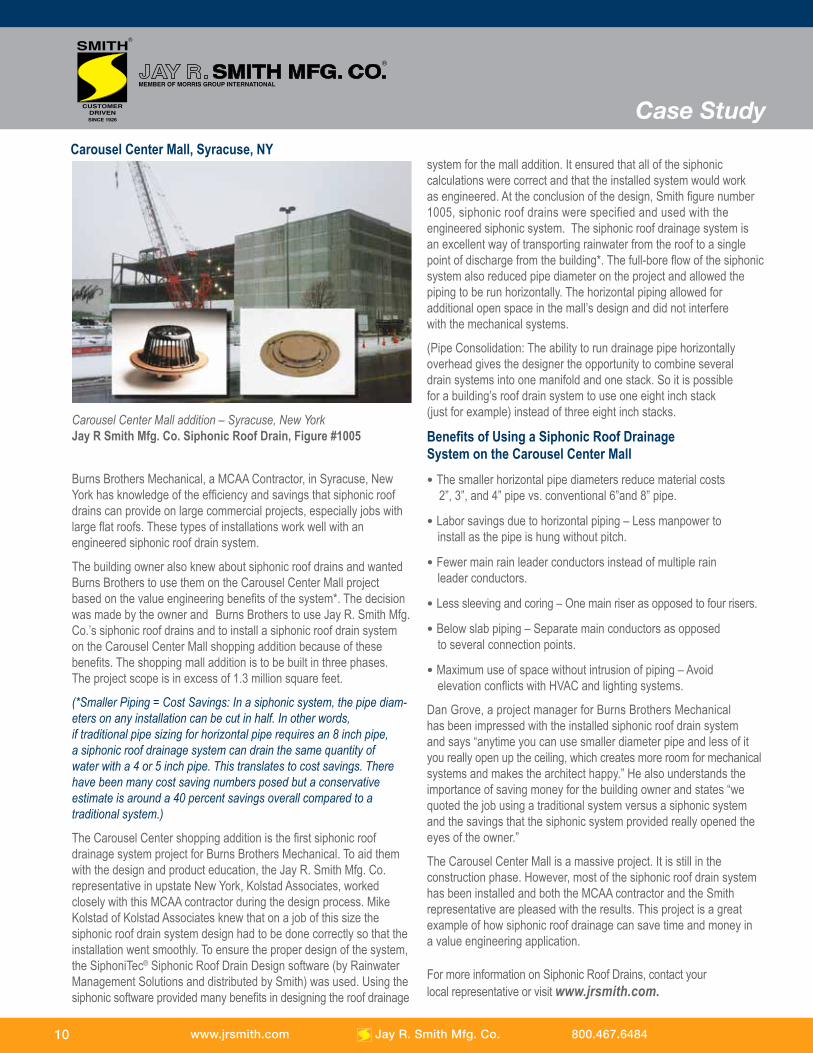
Burns Brothers Mechanical, a MCAA Contractor, in Syracuse, New York has knowledge of the efficiency and savings that siphonic roof drains can provide on large commercial projects, especially jobs with large flat roofs. These types of installations work well with anengineered siphonic roof drain system. The building owner also knew about siphonic roof drains and wanted Burns Brothers to use them on the Carousel Center Mall project based on the value engineering benefits of the system*. The decision was made by the owner and Burns Brothers to use Jay R. Smith Mfg. Co.’s siphonic roof drains and to install a siphonic roof drain system on the Carousel Center Mall shopping addition because of these benefits. The shopping mall addition is to be built in three phases. The project scope is in excess of 1.3 million square feet.
(*Smaller Piping = Cost Savings: In a siphonic system, the pipe diam-eters on any installation can be cut in half. In other words, if traditional pipe sizing for horizontal pipe requires an 8 inch pipe,a siphonic roof drainage system can drain the same quantity of water with a 4 or 5 inch pipe. This translates to cost savings. There have been many cost saving numbers posed but a conservative estimate is around a 40 percent savings overall compared to a traditional system.)
The Carousel Center shopping addition is the first siphonic roof drainage system project for Burns Brothers Mechanical. To aid them with the design and product education, the Jay R. Smith Mfg. Co. representative in upstate New York, Kolstad Associates, worked closely with this MCAA contractor during the design process. Mike Kolstad of Kolstad Associates knew that on a job of this size the siphonic roof drain system design had to be done correctly so that the installation went smoothly. To ensure the proper design of the system, the SiphoniTec® Siphonic Roof Drain Design software (by Rainwater Management Solutions and distributed by Smith) was used. Using the siphonic software provided many benefits in designing the roof drainage
system for the mall addition. It ensured that all of the siphonic calculations were correct and that the installed system would work as engineered. At the conclusion of the design, Smith figure number 1005, siphonic roof drains were specified and used with the engineered siphonic system. The siphonic roof drainage system is an excellent way of transporting rainwater from the roof to a single point of discharge from the building*. The full-bore flow of the siphonicsystem also reduced pipe diameter on the project and allowed the piping to be run horizontally. The horizontal piping allowed for additional open space in the mall’s design and did not interfere with the mechanical systems.
(Pipe Consolidation: The ability to run drainage pipe horizontally overhead gives the designer the opportunity to combine several drain systems into one manifold and one stack. So it is possible for a building’s roof drain system to use one eight inch stack (just for example) instead of three eight inch stacks.
Benefits of Using a Siphonic Roof Drainage System on the Carousel Center Mall • The smaller horizontal pipe diameters reduce material costs 2”, 3”, and 4” pipe vs. conventional 6”and 8” pipe.
• Labor savings due to horizontal piping – Less manpower to install as the pipe is hung without pitch.
• Fewer main rain leader conductors instead of multiple rain leader conductors.
• Less sleeving and coring – One main riser as opposed to four risers.
• Below slab piping – Separate main conductors as opposed to several connection points.
• Maximum use of space without intrusion of piping – Avoid elevation conflicts with HVAC and lighting systems. Dan Grove, a project manager for Burns Brothers Mechanical has been impressed with the installed siphonic roof drain system and says “anytime you can use smaller diameter pipe and less of it you really open up the ceiling, which creates more room for mechanical systems and makes the architect happy.” He also understands the importance of saving money for the building owner and states “we quoted the job using a traditional system versus a siphonic system and the savings that the siphonic system provided really opened the eyes of the owner.”
The Carousel Center Mall is a massive project. It is still in the construction phase. However, most of the siphonic roof drain system has been installed and both the MCAA contractor and the Smith representative are pleased with the results. This project is a great example of how siphonic roof drainage can save time and money in a value engineering application.
For more information on Siphonic Roof Drains, contact yourlocal representative or visit www.jrsmith.com.
Carousel Center Mall, Syracuse, NY
Carousel Center Mall addition – Syracuse, New YorkJay R Smith Mfg. Co. Siphonic Roof Drain, Figure #1005
10
Case Study
www.jrsmith.com Jay R. Smith Mfg. Co. 800.467.6484
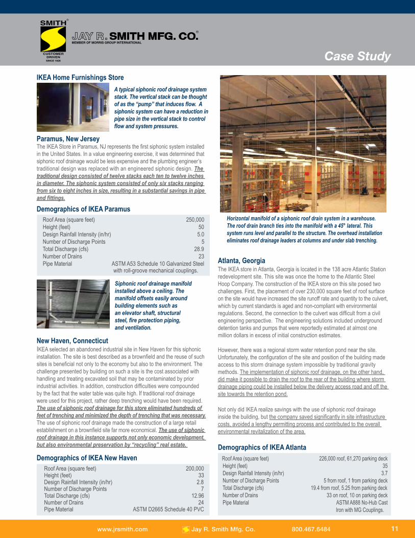
Paramus, New JerseyThe IKEA Store in Paramus, NJ represents the first siphonic system installed in the United States. In a value engineering exercise, it was determined that siphonic roof drainage would be less expensive and the plumbing engineer’s traditional design was replaced with an engineered siphonic design. The traditional design consisted of twelve stacks each ten to twelve inches in diameter. The siphonic system consisted of only six stacks ranging from six to eight inches in size, resulting in a substantial savings in pipe and fittings.
Demographics of IKEA Paramus Roof Area (square feet) 250,000 Height (feet) 50 Design Rainfall Intensity (in/hr) 5.0 Number of Discharge Points 5 Total Discharge (cfs) 28.9 Number of Drains 23 Pipe Material ASTM A53 Schedule 10 Galvanized Steel with roll-groove mechanical couplings.
New Haven, ConnecticutIKEA selected an abandoned industrial site in New Haven for this siphonic installation. The site is best described as a brownfield and the reuse of such sites is beneficial not only to the economy but also to the environment. The challenge presented by building on such a site is the cost associated with handling and treating excavated soil that may be contaminated by prior industrial activities. In addition, construction difficulties were compounded by the fact that the water table was quite high. If traditional roof drainage were used for this project, rather deep trenching would have been required. The use of siphonic roof drainage for this store eliminated hundreds of feet of trenching and minimized the depth of trenching that was necessary. The use of siphonic roof drainage made the construction of a large retail establishment on a brownfield site far more economical. The use of siphonic roof drainage in this instance supports not only economic development, but also environmental preservation by “recycling” real estate.
Demographics of IKEA New Haven Roof Area (square feet) 200,000 Height (feet) 33 Design Rainfall Intensity (in/hr) 2.8 Number of Discharge Points 7 Total Discharge (cfs) 12.96 Number of Drains 24 Pipe Material ASTM D2665 Schedule 40 PVC
Atlanta, GeorgiaThe IKEA store in Atlanta, Georgia is located in the 138 acre Atlantic Station redevelopment site. This site was once the home to the Atlantic Steel Hoop Company. The construction of the IKEA store on this site posed two challenges. First, the placement of over 230,000 square feet of roof surface on the site would have increased the site runoff rate and quantity to the culvert, which by current standards is aged and non-compliant with environmental regulations. Second, the connection to the culvert was difficult from a civilengineering perspective. The engineering solutions included underground detention tanks and pumps that were reportedly estimated at almost one million dollars in excess of initial construction estimates.
However, there was a regional storm water retention pond near the site. Unfortunately, the configuration of the site and position of the building made access to this storm drainage system impossible by traditional gravity methods. The implementation of siphonic roof drainage, on the other hand, did make it possible to drain the roof to the rear of the building where storm drainage piping could be installed below the delivery access road and off the site towards the retention pond.
Not only did IKEA realize savings with the use of siphonic roof drainage inside the building, but the company saved significantly in site infrastructure costs, avoided a lengthy permitting process and contributed to the overall environmental revitalization of the area.
Demographics of IKEA Atlanta Roof Area (square feet) 226,000 roof, 61,270 parking deck Height (feet) 35 Design Rainfall Intensity (in/hr) 3.7 Number of Discharge Points 5 from roof, 1 from parking deck Total Discharge (cfs) 19.4 from roof, 5.25 from parking deck Number of Drains 33 on roof, 10 on parking deck Pipe Material ASTM A888 No-Hub Cast Iron with MG Couplings.
A typical siphonic roof drainage system stack. The vertical stack can be thought of as the “pump” that induces flow. A siphonic system can have a reduction in pipe size in the vertical stack to control flow and system pressures.
IKEA Home Furnishings Store
Siphonic roof drainage manifold installed above a ceiling. The manifold offsets easily around building elements such as an elevator shaft, structural steel, fire protection piping, and ventilation.
Horizontal manifold of a siphonic roof drain system in a warehouse. The roof drain branch ties into the manifold with a 45° lateral. This system runs level and parallel to the structure. The overhead installationeliminates roof drainage leaders at columns and under slab trenching.
11
Case Study
www.jrsmith.com Jay R. Smith Mfg. Co. 800.467.6484
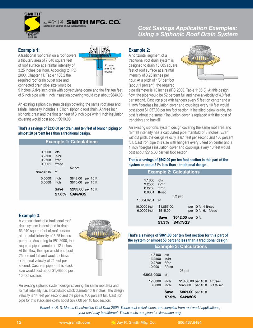
Example 1:A traditional roof drain on a roof covers a tributary area of 7,840 square feet of roof surface at a rainfall intensity of 3.25 inches per hour. According to IPC 2000, Chapter 11, Table 1106.2 the required roof drain outlet size and connected drain pipe size would be 5 inches. A five inch drain with polyethylene dome and the first ten feet of 5 inch pipe with 1 inch insulation covering would cost about $840.00.
An existing siphonic system design covering the same roof area and rainfall intensity includes a 3 inch siphonic roof drain. A three inch siphonic drain and the first ten feet of 3 inch pipe with 1 inch insulation covering would cost about $610.00.
That’s a savings of $233.00 per drain and ten feet of branch piping or almost 28 percent less than a traditional design.
3" outletand 10 ft.of pipe
Example 2: A horizontal segment of a traditional roof drain system is designed to drain 15,685 square feet of roof surface at a rainfall intensity of 3.25 inches per hour. At a pitch of 1/8” per foot (about 1 percent), the required pipe diameter is 10 inches (IPC 2000, Table 1106.3). At this design flow, the pipe would be 52 percent full and have a velocity of 4.0 feet per second. Cast iron pipe with hangers every 5 feet on center and a 1 inch fiberglass insulation cover and couplings every 10 feet would cost about $1,057.00 per ten foot section. If installed below grade, the cost is about the same if insulation cover is replaced with the cost of trenching and backfill.
An existing siphonic system design covering the same roof area and rainfall intensity has a calculated pipe manifold of 6 inches. Even without pitch, the design velocity is 6.1 feet per second and 100 percent full. Cast iron pipe this size with hangers every 5 feet on center and a 1 inch fiberglass insulation cover and couplings every 10 feet would cost about $515.00 per ten foot section.
That’s a savings of $542.00 per ten foot section in this part of the system or about 51% less than a traditional design.
Example 3:A vertical stack of a traditional roof drain system is designed to drain 63,940 square feet of roof surface at a rainfall intensity of 3.25 inches per hour. According to IPC 2000, the required pipe diameter is 12 inches. At this flow, the pipe would be about 25 percent full and would achieve a terminal velocity of 24 feet per second. Cast iron pipe for this stack size would cost about $1,488.00 per 10 foot section.
An existing siphonic system design covering the same roof area and rainfall intensity has a calculated stack diameter of 8 inches. The design velocity is 14 feet per second and the pipe is 100 percent full. Cast iron pipe for this stack size costs about $627.00 per 10 foot section.
Based on R. S. Means Construction Cost Data 2005. These cost calculations are examples from real world applications; your cost may be different. These costs are given for illustration only.
That’s a savings of $861.00 per ten foot section for this part of the system or almost 58 percent less than a traditional design.
Cost Savings Application Examples: Using a Siphonic Roof Drain System
12
Example 1: Calculations
0.5900 cfs 3.2500 in/hr 0.2708 ft/hr 0.0001 ft/sec 52 pct 7842.4615 sf 5.0000 inch $843.00 per 10 ft 3.0000 inch $610.00 per 10 ft Save $233.00 per 10 ft 27.6% SAVINGS
Example 2: Calculations
1.1800 cfs 3.2500 in/hr 0.2708 ft/hr 0.0001 ft/sec 52 pct 15684.9231 sf 10.0000 inch $1,057.00 per 10 ft 4 ft/sec 6.0000 inch $515.00 per 10 ft 6.1 ft/sec Save $542.00 per 10 ft 51.3% SAVINGS
Example 3: Calculations
4.8100 cfs 3.2500 in/hr 0.2708 ft/hr 0.0001 ft/sec 25 pct 63936.0000 sf 12.0000 inch $1,488.00 per 10 ft 4 ft/sec 8.0000 inch $627.00 per 10 ft 6.1 ft/sec Save $861.00 per 10 ft 57.9% SAVINGS
www.jrsmith.com Jay R. Smith Mfg. Co. 800.467.6484
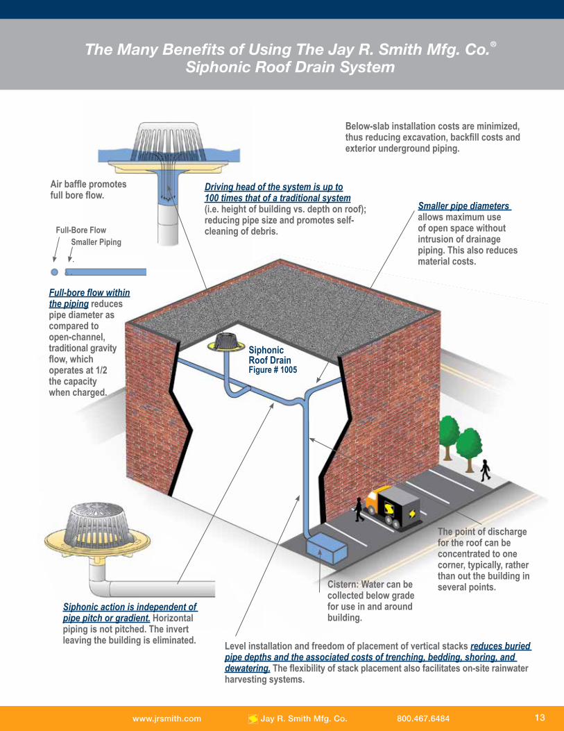
The Many Benefits of Using The Jay R. Smith Mfg. Co.®
Siphonic Roof Drain System
Level installation and freedom of placement of vertical stacks reduces buried pipe depths and the associated costs of trenching, bedding, shoring, and dewatering. The flexibility of stack placement also facilitates on-site rainwater harvesting systems.
Driving head of the system is up to100 times that of a traditional system (i.e. height of building vs. depth on roof); reducing pipe size and promotes self-cleaning of debris.
Smaller pipe diameters allows maximum use of open space without intrusion of drainage piping. This also reduces material costs.
Below-slab installation costs are minimized, thus reducing excavation, backfill costs and exterior underground piping.
Air baffle promotes full bore flow.
Siphonic Roof DrainFigure # 1005
The point of discharge for the roof can beconcentrated to one corner, typically, rather than out the building in several points.Cistern: Water can be
collected below grade for use in and around building.
Siphonic action is independent of pipe pitch or gradient. Horizontal piping is not pitched. The invert leaving the building is eliminated.
Full-bore flow withinthe piping reduces pipe diameter as compared to open-channel, traditional gravity flow, which operates at 1/2 the capacity when charged.
Full-Bore FlowSmaller Piping
13www.jrsmith.com Jay R. Smith Mfg. Co. 800.467.6484

SPM1104-1402
MORRIS GROUP INTERNATIONAL
ACORN ENGINEERING COMPANY Engineered Plumbing Products P.O. Box 3527 • City of Industry, CA 91744-0527 U.S.A.800-488-8999 • 626-336-4561 www.acorneng.com
ACORN-GENCON PLASTICS, LLCInjection Molded Products13818 Oaks Avenue • Chino, CA 91710 U.S.A.Tel: 909-591-8461www.acorn-gencon.com
ACORNVAC, INC. Vacuum Plumbing Systems13818 Oaks Avenue, Chino, CA 91710 U.S.A.Tel: 800-591-9920 • Tel: 909-902-1141www.acornvac.com
CHRONOMITE LABORATORIES, INC.Tankless Electric Water HeatersP.O. Box 3527 • City of Industry, CA 91744-0527 U.S.A.Tel: 800-447-4962www.chronomite.com
ELMCO GROUPManufacturer RepresentativesP.O. Box 3787, City of Industry, CA 91744 U.S.A.Tel: 626-333-9942 www.morrisgroup.co
MORRIS INdUSTRIES MExICO, S. dE R.L. dE C.V.Central and Latin America Manufacturing and SalesMaquiladoras #1387-1 Col.Cd. Industrial Tijuana, B.C., C.P. 22444Tel: 011-52-664-623-4580 www.morrisgroup.co
MORRIS PROPERTY MANAGEMENT COMPANYConstruction, Interior Design, Landscaping and Maintenance15058 Proctor Avenue • City of Industry, CA 91746 U.S.A.Tel: 626-855-4888 www.morrispropertiesmgt.com
MURdOCk MANUFACTURINGDrinking Fountains and HydrantsP.O. Box 3527 • City of Industry, CA 91744-0527 U.S.A.Tel: 800-45-DRINK • 626-333-2543 www.murdockmfg.com
POTTER ROEMER Fire Protection EquipmentP.O. Box 3527 • City of Industry, CA 91744-0527 U.S.A.Tel: 800-366-3473www.pot terroemer.com
WHITEHALL MANUFACTURINGHospital and Rehabilitation ProductsP.O. Box 3527 • City of Industry, CA 91744-0527 U.S.A.Tel: 800-782-7706 • 626-968-6681www.whitehallmfg.com
Innovative Spirit and
Engineering Foundation
“What sets us apart from competitors
is our engineering and spirit. We have
a ‘can-do’ spirit. If you ask us to
do something, we will do it or figure
out how to do it. That’s the part our
customers like, that’s the part we like.”
- Don Morris, President and CEO
JAy R. SMITh MfG. CO.®
Plumbing and Drainage ProductsP.O. Box 3237 • Montgomery, AL 36109-0237Tel: 800-467-6484 • 334-277-8520 www.jrsmith.com