siprotec 7sj600 numerical overcurrent, motor and overload...
TRANSCRIPT
SIPROTEC 7SJ600Numerical Overcurrent, Motorand Overload Relay
Protection Systems
CatalogLSA 2.1.15 ⋅ 1997
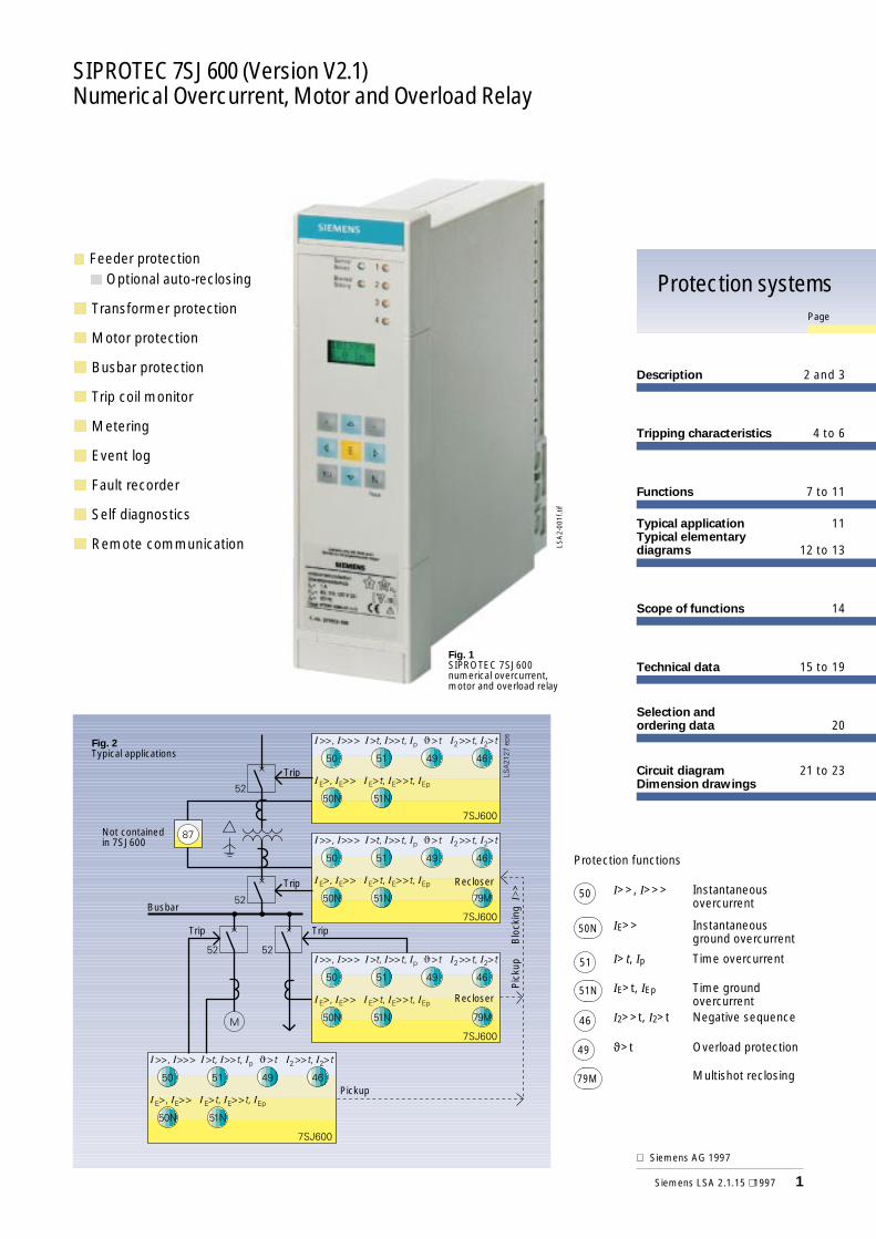
SIPROTEC 7SJ600 (Version V2.1)Numerical Overcurrent, Motor and Overload Relay
Fig. 1SIPROTEC 7SJ600numerical overcurrent,motor and overload relay
Protection systemsPage
Description 2 and 3
Tripping characteristics 4 to 6
Functions 7 to 11
Typical application 11Typical elementarydiagrams 12 to 13
Scope of functions 14
Technical data 15 to 19
Selection andordering data 20
LSA
2-00
1f.ti
f
Circuit diagram 21 to 23Dimension drawings
n Feeder protection
n Optional auto-reclosing
n Transformer protection
nMotor protection
n Busbar protection
n Trip coil monitor
nMetering
n Event log
n Fault recorder
n Self diagnostics
n Remote communication
Trip
Busbar
Trip Trip
Pickup
Pic
kup
Blo
ckin
gI>
>
Fig. 2Typical applications
Recloser
RecloserTrip
Not containedin 7SJ600
Siemens LSA 2.1.15 ⋅ 1997 1
Siemens AG 1997
Protection functions
50 I>>, I>>> Instantaneousovercurrent
50N IE>> Instantaneousground overcurrent
51 I>t, Ip Time overcurrent
51N IE>t, IEp Time groundovercurrent
46 I2>>t, I2>t Negative sequence
49 ϑ>t Overload protection
79M Multishot reclosing
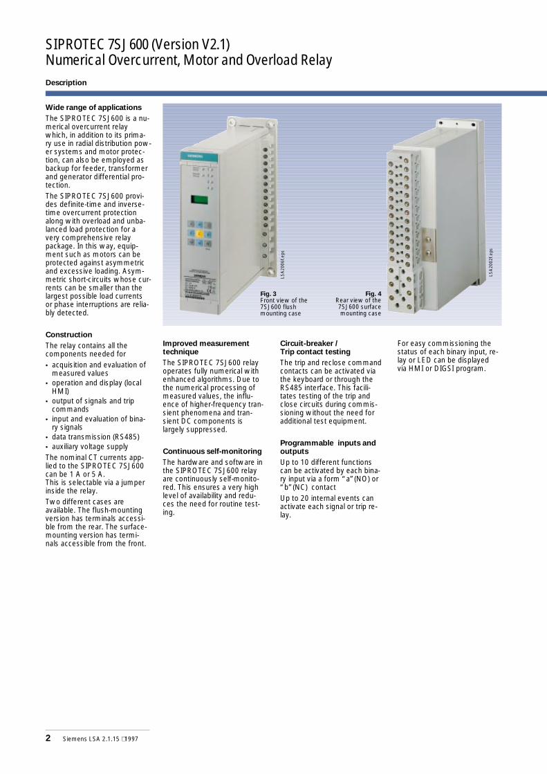
SIPROTEC 7SJ600 (Version V2.1)Numerical Overcurrent, Motor and Overload Relay
Wide range of applications
The SIPROTEC 7SJ600 is a nu-merical overcurrent relaywhich, in addition to its prima-ry use in radial distribution pow-er systems and motor protec-tion, can also be employed asbackup for feeder, transformerand generator differential pro-tection.The SIPROTEC 7SJ600 provi-des definite-time and inverse-time overcurrent protectionalong with overload and unba-lanced load protection for avery comprehensive relaypackage. In this way, equip-ment such as motors can beprotected against asymmetricand excessive loading. Asym-metric short-circuits whose cur-rents can be smaller than thelargest possible load currentsor phase interruptions are relia-bly detected.
Construction
The relay contains all thecomponents needed for• acquisition and evaluation of
measured values• operation and display (local
HMI)• output of signals and trip
commands• input and evaluation of bina-
ry signals• data transmission (RS485)• auxiliary voltage supplyThe nominal CT currents app-lied to the SIPROTEC 7SJ600can be 1 A or 5 A.This is selectable via a jumperinside the relay.Two different cases areavailable. The flush-mountingversion has terminals accessi-ble from the rear. The surface-mounting version has termi-nals accessible from the front.
Improved measurementtechnique
The SIPROTEC 7SJ600 relayoperates fully numerical withenhanced algorithms. Due tothe numerical processing ofmeasured values, the influ-ence of higher-frequency tran-sient phenomena and tran-sient DC components islargely suppressed.
Continuous self-monitoring
The hardware and software inthe SIPROTEC 7SJ600 relayare continuously self-monito-red. This ensures a very highlevel of availability and redu-ces the need for routine test-ing.
Circuit-breaker /Trip contact testing
The trip and reclose commandcontacts can be activated viathe keyboard or through theRS485 interface. This facili-tates testing of the trip andclose circuits during commis-sioning without the need foradditional test equipment.
Programmable inputs andoutputs
Up to 10 different functionscan be activated by each bina-ry input via a form “a”(NO) or“b”(NC) contactUp to 20 internal events canactivate each signal or trip re-lay.
For easy commissioning thestatus of each binary input, re-lay or LED can be displayedvia HMI or DIGSI program.
2 Siemens LSA 2.1.15 ⋅ 1997
Description
Fig. 3Front view of the7SJ600 flushmounting case
Fig. 4Rear view of the7SJ600 surfacemounting case
LSA
2006
f.eps
LSA
2002
f.eps
Siemens LSA 2.1.15 ⋅ 1997 3
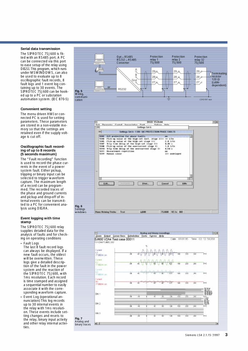
Serial data transmission
The SIPROTEC 7SJ600 is fit-ted with an RS485 port. A PCcan be connected via this portto ease setup of the relay usingDIGSI. This program, which runsunder MSWINDOWS, can alsobe used to evaluate up to 8oscillographic fault records, 8fault logs and 1 event log con-taining up to 30 events. TheSIPROTEC 7SJ600 can be hook-ed up to a PC or substationautomation system. (IEC 870-5)
Convenient setting
The menu driven HMI or con-nected PC is used for settingparameters. These parametersare stored in a non-volatile me-mory so that the settings areretained even if the supply volt-age is cut off.
Oscillographic fault record-ing of up to 8 records(5 seconds maximum)
The “Fault recording” functionis used to record the phase cur-rents in the event of a powersystem fault. Either pickup,tripping or binary input can beselected to trigger waveformcapture. The maximum lengthof a record can be program-med. The recorded traces ofthe phase and ground currentsand pickup and drop-off of in-ternal events can be transmit-ted to a PC for convenient ana-lysis using DIGRA.
Event logging with timestamp
The SIPROTEC 7SJ600 relaysupplies detailed data for theanalysis of faults and for check-ing on operating conditions• Fault Logs
The last 8 fault record logscan always be displayed. If anew fault occurs, the oldestwill be overwritten. Theselogs give a detailed descrip-tion of the fault in the powersystem and the reaction ofthe SIPROTEC 7SJ600, with1ms resolution. Each recordis time stamped and assigneda sequential number to easilyassociate it with the corre-sponding waveform capture.
• Event Log (operational an-nunciation) This log recordsup to 30 internal events inthe relay with 1ms resoluti-on. These events include set-ting changes and resets tothe relay, binary input activityand other relay internal activi-ties.
or
Opt↔RS485RS232↔RS485Converter
Protectionrelay 17SJ600
Protectionrelay 27SJ600
Protectionrelay 327SJ600
Terminatingresistor120 Ω(cable-dependent)
Fig. 5Wiring,communi-cation
Fig. 6Settingswindows
Fig. 7Analog andbinary traces
SIPROTEC 7SJ600 (Version V2.1)Numerical Overcurrent, Motor and Overload Relay
4 Siemens LSA 2.1.15 ⋅ 1997
Tripping characteristics
t =−
+F
HGGG
I
KJJJ
⋅8 9341
10179662 0938
.
I I.
.p
De j
t =−
+F
HGGG
I
KJJJ
⋅0 2663
10 0339312969
.
I I.
.p
De j
ç
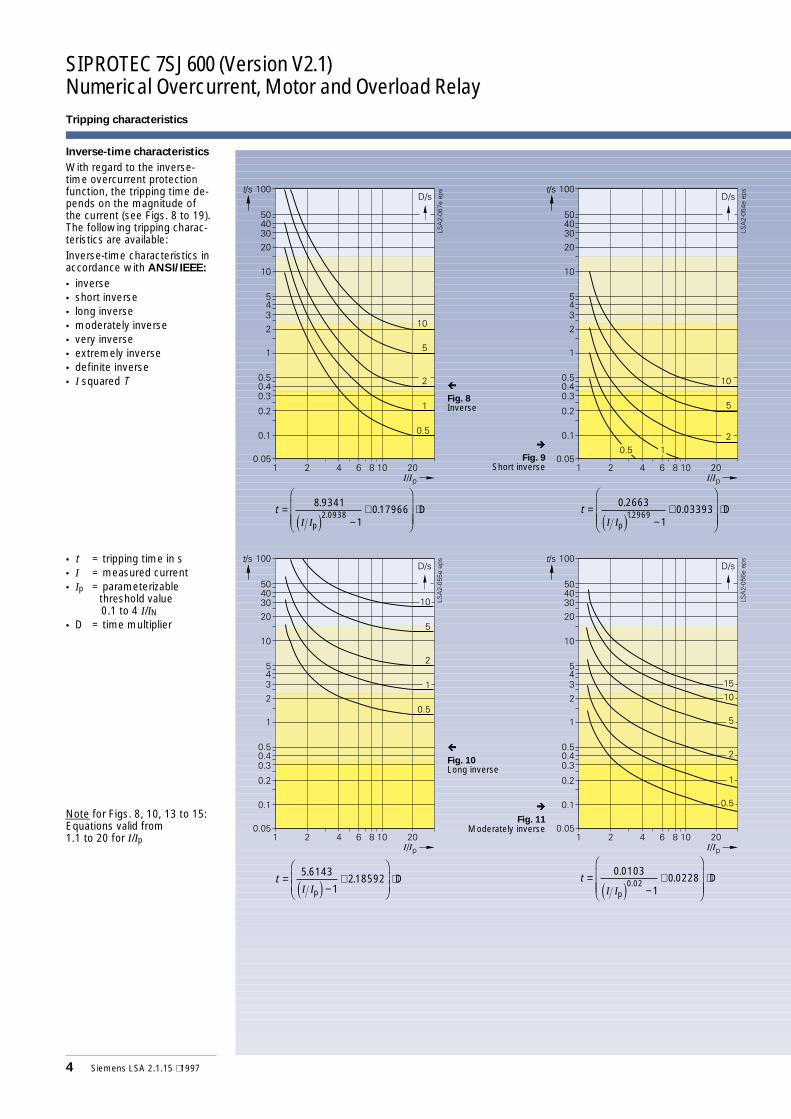
Fig. 8Inverse
è
Fig. 9Short inverse
t =−
+F
HGG
I
KJJ ⋅5 6143
1218592
.
I I.
pD
e jt =
−+
F
HGGG
I
KJJJ
⋅0 0103
10 02280 02
.
I I.
.p
De j
ç
Fig. 10Long inverse
è
Fig. 11Moderately inverse
Inverse-time characteristics
With regard to the inverse-time overcurrent protectionfunction, the tripping time de-pends on the magnitude ofthe current (see Figs. 8 to 19).The following tripping charac-teristics are available:Inverse-time characteristics inaccordance with ANSI/IEEE:
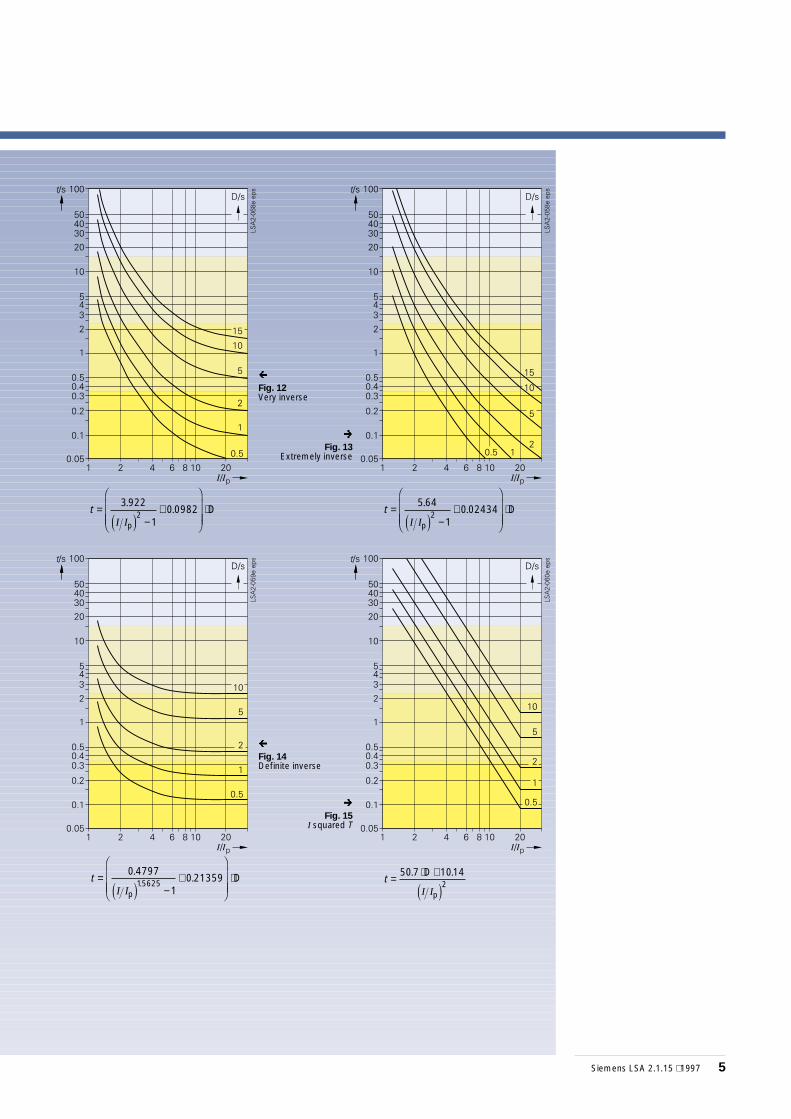
• inverse• short inverse• long inverse• moderately inverse• very inverse• extremely inverse• definite inverse• I squared T
• t = tripping time in s• I = measured current• Ip = parameterizable
threshold value0.1 to 4 I/IN
• D = time multiplier
Note for Figs. 8, 10, 13 to 15:Equations valid from1.1 to 20 for I/Ip
Siemens LSA 2.1.15 ⋅ 1997 5
t =−
+F
HGGG
I
KJJJ
⋅3922
10 09822
.
I I.
p
De j
t =−
+F
HGGG
I
KJJJ
⋅5 64
10 024342
.
I I.
p
De j
t =−
+F
HGGG
I
KJJJ
⋅0 4797
10 2135915625
.
I I.
.p
De j
ç
Fig. 12Very inverse
è
Fig. 13Extremely inverse
ç
Fig. 14Definite inverse
è
Fig. 15I squared T
t = ⋅ +50 7 10142
. .
I I
D
pe j
SIPROTEC 7SJ600 (Version V2.1)Numerical Overcurrent, Motor and Overload Relay
6 Siemens LSA 2.1.15 ⋅ 1997
Tripping characteristics
t T= ⋅014
0 02.
I I.
pp
e jt T=
−⋅
135
1
.
I Ipp
e j
tI I
=−
⋅80
12
pp
e jT t T=
−⋅
120
1I Ipp
e j
ç
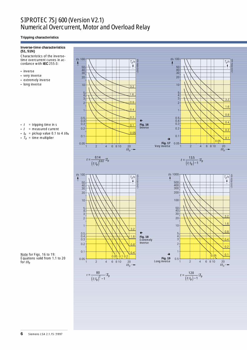
Fig. 16Inverse
è
Fig. 17Very inverse
ç
Fig. 18Extremelyinverse
è
Fig. 19Long inverse
Inverse-time characteristics(51, 51N)
Characteristics of the inverse-time overcurrent curves in ac-cordance with IEC 255-3:
• inverse• very inverse• extremely inverse• long inverse
• t = tripping time in s• I = measured current• Ip = pickup value 0.1 to 4 I/IN• Tp = time multiplier
Note for Figs. 16 to 19:Equations valid from 1.1 to 20for I/Ip
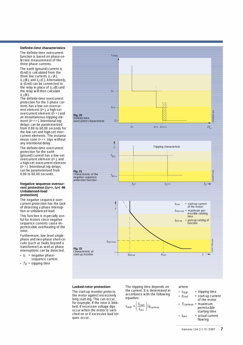
Definite-time characteristics
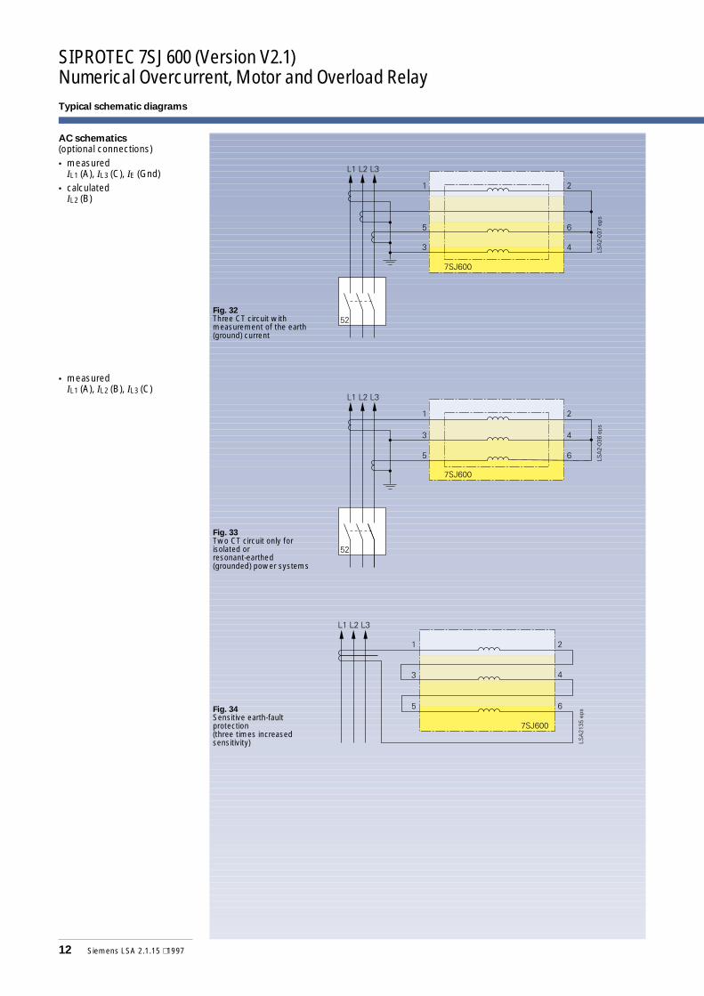
The definite-time overcurrentfunction is based on phase-se-lective measurement of thethree phase currents.The earth (ground) current IE(Gnd) is calculated from thethree line currents IL1 (A),IL2(B), and IL3(C). Alternatively,IE (Gnd) can be connected tothe relay in place of IL2(B) andthe relay will then calculateIL2(B).The definite-time overcurrentprotection for the 3 phase cur-rents has a low-set overcur-rent element (I>), a high-setovercurrent element (I>>) andan instantaneous-tripping ele-ment (I>>>). Intentional tripdelays can be parameterizedfrom 0.00 to 60.00 seconds forthe low-set and high-set over-current elements. The instanta-neous zone I>>> trips withoutany intentional delay.The definite-time overcurrentprotection for the earth(ground) current has a low-setovercurrent element (I>), anda high-set overcurrent element(I>>). Intentional trip delayscan be parameterized from0.00 to 60.00 seconds.
Negative sequence overcur-rent protection (I2>>, I2>/ 46Unbalanced-loadprotection)
The negative sequence over-current protection has the taskof detecting a phase interrup-tion or unbalanced load.This function is especially use-ful for motors since negativesequence currents cause im-permissible overheating of therotor.Furthermore, low level single-phase and two-phase short-cir-cuits (such as faults beyond atransformer) as well as phaseinterruptions can be detected.• I2 = negative phase-
sequence current• TI2 = tripping time
Siemens LSA 2.1.15 ⋅ 1997 7
Locked-rotor protection
The start-up monitor protectsthe motor against excessivelylong start-ing. This can occur,for example, if the rotor is blok-ked, if excessive voltage dipsoccur when the motor is swit-ched on or if excessive load tor-ques occur.
The tripping time depends onthe current. It is determined inaccordance with the followingequation:
where• tTRIP = tripping time• IStart = start-up current
of the motor• TStartmax = maximum
permissiblestarting time
• Irms = actual currentflowing
tI
ItTRIP
Start
rmsStartmax=
FHG
IKJ
⋅
Fig. 20Definite-timeovercurrent characteristic
Delay
Fig. 21Characteristic of thenegative sequenceprotection function
Tripping characteristic
Fig. 22Characteristic ofstart-up monitor
tStart max
Ipick-up IStart
IStart = start-up currentof the motor
IStart max = maximum per-missible startingtime
Ipick-up = pick-up setting offunction
t
I
SIPROTEC 7SJ600 (Version V2.1)Numerical Overcurrent, Motor and Overload Relay
8 Siemens LSA 2.1.15 ⋅ 1997
Tripping characteristics
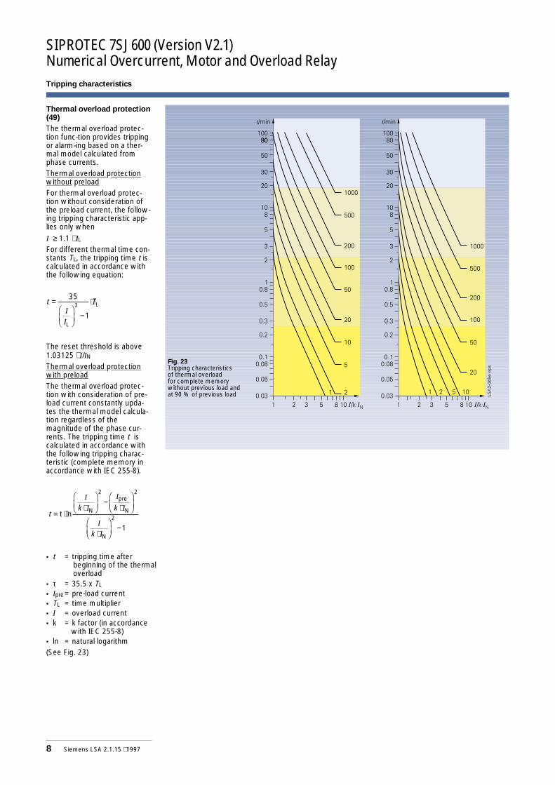
Fig. 23Tripping characteristicsof thermal overloadfor complete memorywithout previous load andat 90 % of previous load
Thermal overload protection(49)
The thermal overload protec-tion func-tion provides trippingor alarm-ing based on a ther-mal model calculated fromphase currents.Thermal overload protectionwithout preloadFor thermal overload protec-tion without consideration ofthe preload current, the follow-ing tripping characteristic app-lies only whenI ≥ 1.1 ⋅ ILFor different thermal time con-stants TL, the tripping time t iscalculated in accordance withthe following equation:
The reset threshold is above1.03125 ⋅ I/INThermal overload protectionwith preloadThe thermal overload protec-tion with consideration of pre-load current constantly upda-tes the thermal model calcula-tion regardless of themagnitude of the phase cur-rents. The tripping time t iscalculated in accordance withthe following tripping charac-teristic (complete memory inaccordance with IEC 255-8).
• t = tripping time afterbeginning of the thermaloverload
• τ = 35.5 x TL
• Ipre = pre-load current• TL = time multiplier• I = overload current• k = k factor (in accordance
with IEC 255-8)• ln = natural logarithm(See Fig. 23)
t T=FHG
IKJ
−
⋅35
12
I
IL
L
tk k
k
= ⋅⋅
FHG
IKJ
−⋅
FHG
IKJ
⋅FHG
IKJ
−
t ln N
pre
N
N
I
I
I
I
I
I
2 2
2
1
Siemens LSA 2.1.15 ⋅ 1997 9
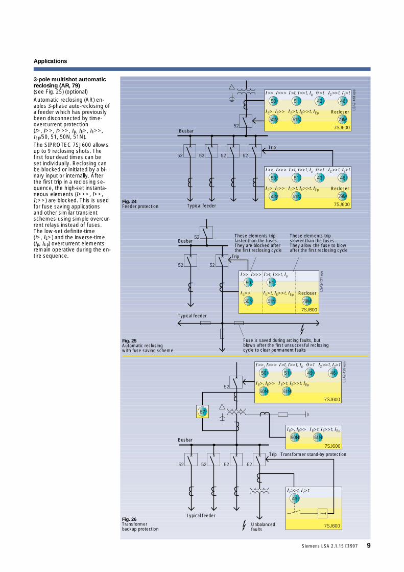
3-pole multishot automaticreclosing (AR, 79)(see Fig. 25) (optional)Automatic reclosing (AR) en-ables 3-phase auto-reclosing ofa feeder which has previouslybeen disconnected by time-overcurrent protection(I>, I>>, I>>>, Ip, IE>, IE>>,IEp/50, 51, 50N, 51N).The SIPROTEC 7SJ600 allowsup to 9 reclosing shots. Thefirst four dead times can beset individually. Reclosing canbe blocked or initiated by a bi-nary input or internally. Afterthe first trip in a reclosing se-quence, the high-set instanta-neous elements (I>>>, I>>,IE>>) are blocked. This is usedfor fuse saving applicationsand other similar transientschemes using simple overcur-rent relays instead of fuses.The low-set definite-time(I>, IE>) and the inverse-time(Ip, IEp) overcurrent elementsremain operative during the en-tire sequence.
Fig. 24Feeder protection
Busbar
Typical feeder
Trip
Recloser
Recloser
Busbar
Typical feeder
Fuse is saved during arcing faults, butblows after the first unsuccesful reclosingcycle to clear permanent faults
These elements tripfaster than the fuses.They are blocked afterthe first reclosing cycle
These elements tripslower than the fuses.They allow the fuse to blowafter the first reclosing cycle
Fig. 25Automatic reclosingwith fuse saving scheme
Trip
Recloser
Busbar
Trip Transformer stand-by protection
Unbalancedfaults
Typical feederFig. 26Transformerbackup protection
Applications
SIPROTEC 7SJ600 (Version V2.1)Numerical Overcurrent, Motor and Overload Relay
10 Siemens LSA 2.1.15 ⋅ 1997
Applications
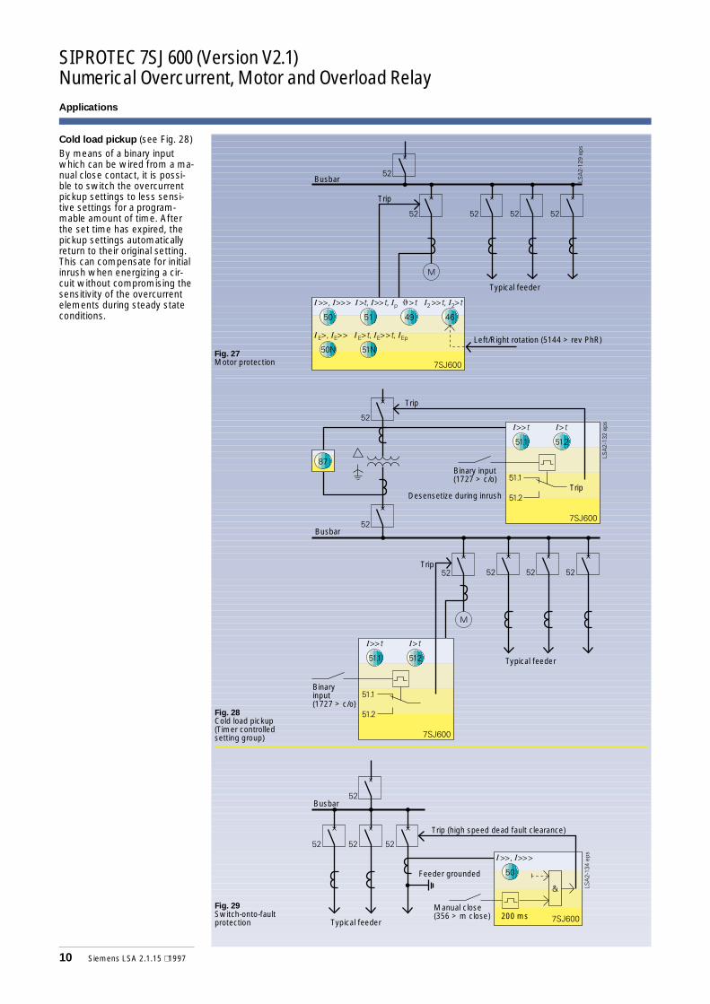
Cold load pickup (see Fig. 28)By means of a binary inputwhich can be wired from a ma-nual close contact, it is possi-ble to switch the overcurrentpickup settings to less sensi-tive settings for a program-mable amount of time. Afterthe set time has expired, thepickup settings automaticallyreturn to their original setting.This can compensate for initialinrush when energizing a cir-cuit without compromising thesensitivity of the overcurrentelements during steady stateconditions.
Fig. 27Motor protection
Busbar
Typical feeder
Trip
Left/Right rotation (5144 > rev PhR)
Busbar
Typical feeder
Fig. 28Cold load pickup(Timer controlledsetting group)
Trip
Trip
Binary input(1727 > c/o)
Desensetize during inrush
Binaryinput(1727 > c/o)
Trip
Fig. 29Switch-onto-faultprotection
Busbar
Trip (high speed dead fault clearance)
Manual close(356 > m close)
Typical feeder
Feeder grounded
200 ms
Applications
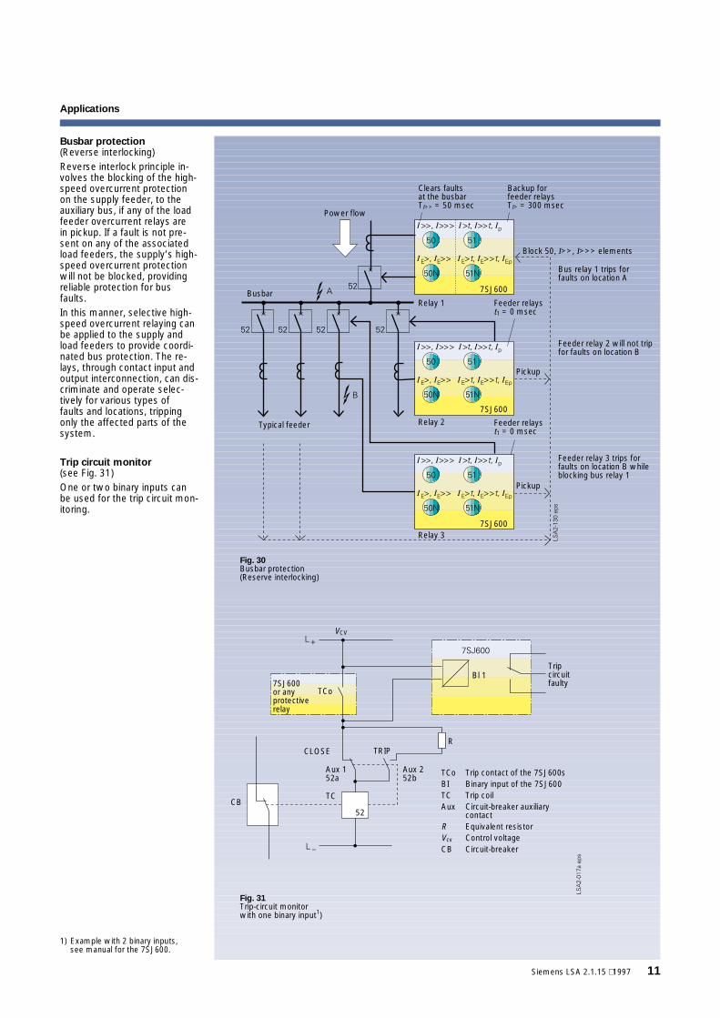
Busbar protection(Reverse interlocking)Reverse interlock principle in-volves the blocking of the high-speed overcurrent protectionon the supply feeder, to theauxiliary bus, if any of the loadfeeder overcurrent relays arein pickup. If a fault is not pre-sent on any of the associatedload feeders, the supply’s high-speed overcurrent protectionwill not be blocked, providingreliable protection for busfaults.In this manner, selective high-speed overcurrent relaying canbe applied to the supply andload feeders to provide coordi-nated bus protection. The re-lays, through contact input andoutput interconnection, can dis-criminate and operate selec-tively for various types offaults and locations, trippingonly the affected parts of thesystem.
Trip circuit monitor(see Fig. 31)One or two binary inputs canbe used for the trip circuit mon-itoring.
Siemens LSA 2.1.15 ⋅ 1997 11
Clears faultsat the busbarTI>> = 50 msec
Backup forfeeder relaysTI> = 300 msec
Power flow
Typical feeder
Busbar
Block 50, I>>, I>>> elements
Bus relay 1 trips forfaults on location A
Feeder relayst1 = 0 msec
Pickup
Feeder relay 2 will not tripfor faults on location B
Feeder relayst1 = 0 msec
Pickup
Feeder relay 3 trips forfaults on location B whileblocking bus relay 1
Relay 3
Relay 2
Relay 1
Fig. 30Busbar protection(Reserve interlocking)
7SJ600
7SJ600
7SJ600
7SJ600or anyprotectiverelay
Tripcircuitfaulty
CLOSE TRIP
TCo Trip contact of the 7SJ600sBI Binary input of the 7SJ600TC Trip coilAux Circuit-breaker auxiliary
contactR Equivalent resistorVcv Control voltageCB Circuit-breaker
Fig. 31Trip-circuit monitorwith one binary input1)
VCV
TCo
Bl 1
Aux 152a
Aux 252b
TC
52CB
R
1) Example with 2 binary inputs,see manual for the 7SJ600.
SIPROTEC 7SJ600 (Version V2.1)Numerical Overcurrent, Motor and Overload Relay
12 Siemens LSA 2.1.15 ⋅ 1997
Typical schematic diagrams
AC schematics(optional connections)• measured
IL1 (A), IL3 (C), IE (Gnd)• calculated
IL2 (B)
• measuredIL1 (A), IL2 (B), IL3 (C)
Fig. 32Three CT circuit withmeasurement of the earth(ground) current
Fig. 33Two CT circuit only forisolated orresonant-earthed(grounded) power systems
Fig. 34Sensitive earth-faultprotection(three times increasedsensitivity)
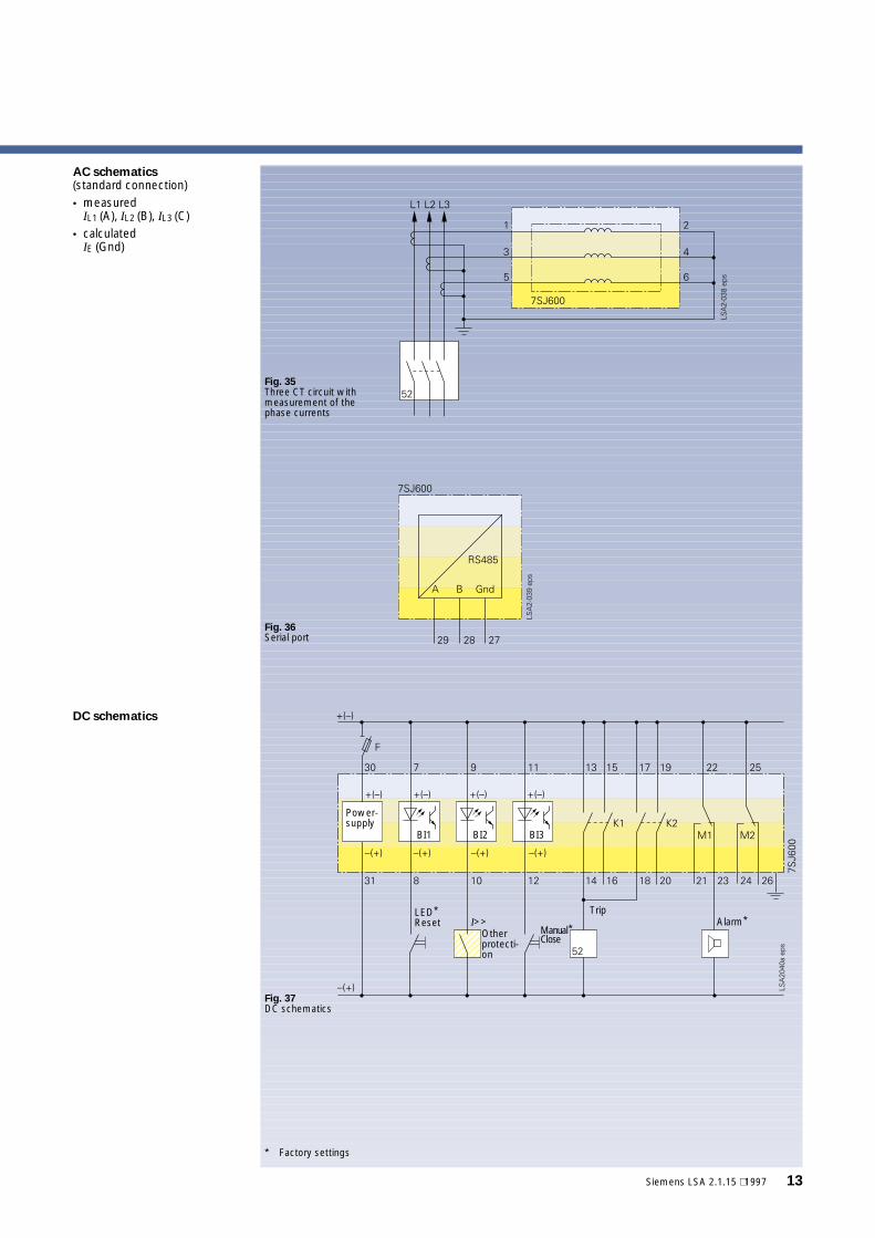
* Factory settings
Fig. 35Three CT circuit withmeasurement of thephase currents
Fig. 36Serial port
AC schematics(standard connection)• measured
IL1 (A), IL2 (B), IL3 (C)• calculated
IE (Gnd)
DC schematics
Siemens LSA 2.1.15 ⋅ 1997 13
Power-supply
BI1 BI2 BI3
I>>Otherprotecti-on
Manual*Close
Alarm*
Fig. 37DC schematics
LED*Reset
Trip
SIPROTEC 7SJ600 (Version V2.1)Numerical Overcurrent, Motor and Overload RelayScope of functions
14 Siemens LSA 2.1.15 ⋅ 1997
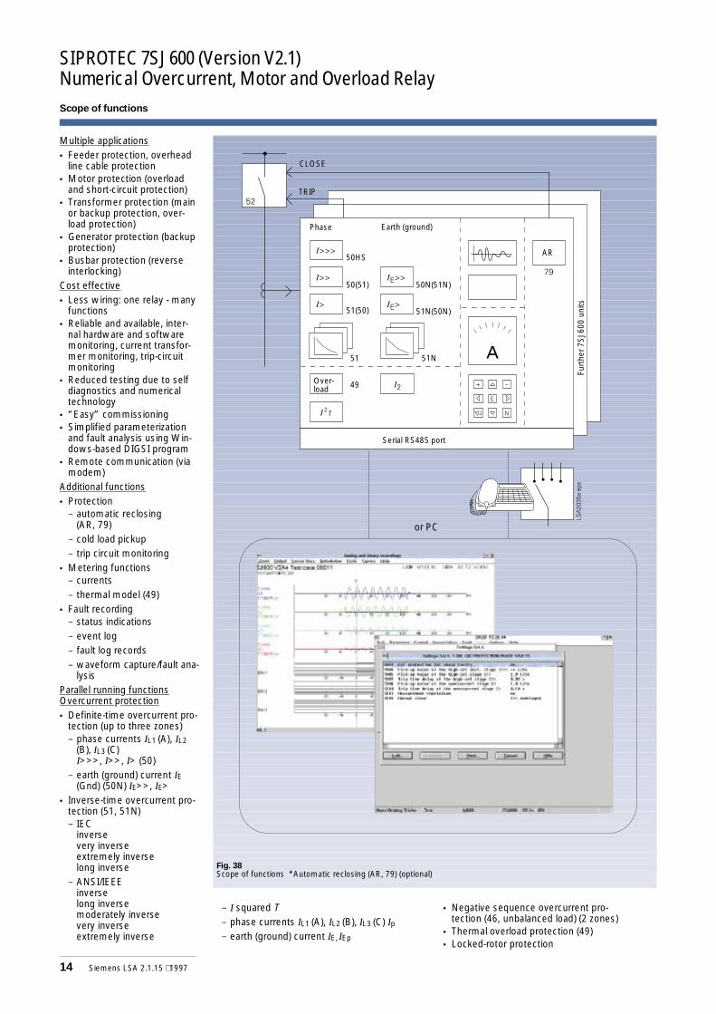
Fig. 38Scope of functions *Automatic reclosing (AR, 79) (optional)
Multiple applications• Feeder protection, overhead
line cable protection• Motor protection (overload
and short-circuit protection)• Transformer protection (main
or backup protection, over-load protection)
• Generator protection (backupprotection)
• Busbar protection (reverseinterlocking)
Cost effective• Less wiring: one relay - many
functions• Reliable and available, inter-
nal hardware and softwaremonitoring, current transfor-mer monitoring, trip-circuitmonitoring
• Reduced testing due to selfdiagnostics and numericaltechnology
• “Easy” commissioning• Simplified parameterization
and fault analysis using Win-dows-based DIGSI program
• Remote communication (viamodem)
Additional functions• Protection
− automatic reclosing(AR, 79)
− cold load pickup− trip circuit monitoring
• Metering functions− currents− thermal model (49)
• Fault recording− status indications− event log− fault log records− waveform capture/fault ana-
lysisParallel running functionsOvercurrent protection• Definite-time overcurrent pro-
tection (up to three zones)− phase currents IL1 (A), IL2
(B), IL3 (C)I>>>, I>>, I> (50)
− earth (ground) current IE(Gnd) (50N) IE>>, IE>
• Inverse-time overcurrent pro-tection (51, 51N)− IEC
inversevery inverseextremely inverselong inverse
− ANSI/IEEEinverselong inversemoderately inversevery inverseextremely inverse
− I squared T− phase currents IL1 (A), IL2 (B), IL3 (C) Ip− earth (ground) current IE, IEp
• Negative sequence overcurrent pro-tection (46, unbalanced load) (2 zones)
• Thermal overload protection (49)• Locked-rotor protection
CLOSE
TRIP
Earth (ground)Phase
Serial RS485 port
Furt
her7
SJ60
0un
its
orPC
AR50HS
50(51)
51(50)
50N(51N)
51N(50N)
51N51
Over-load 49
or PC
Siemens LSA 2.1.15 ⋅ 1997 15
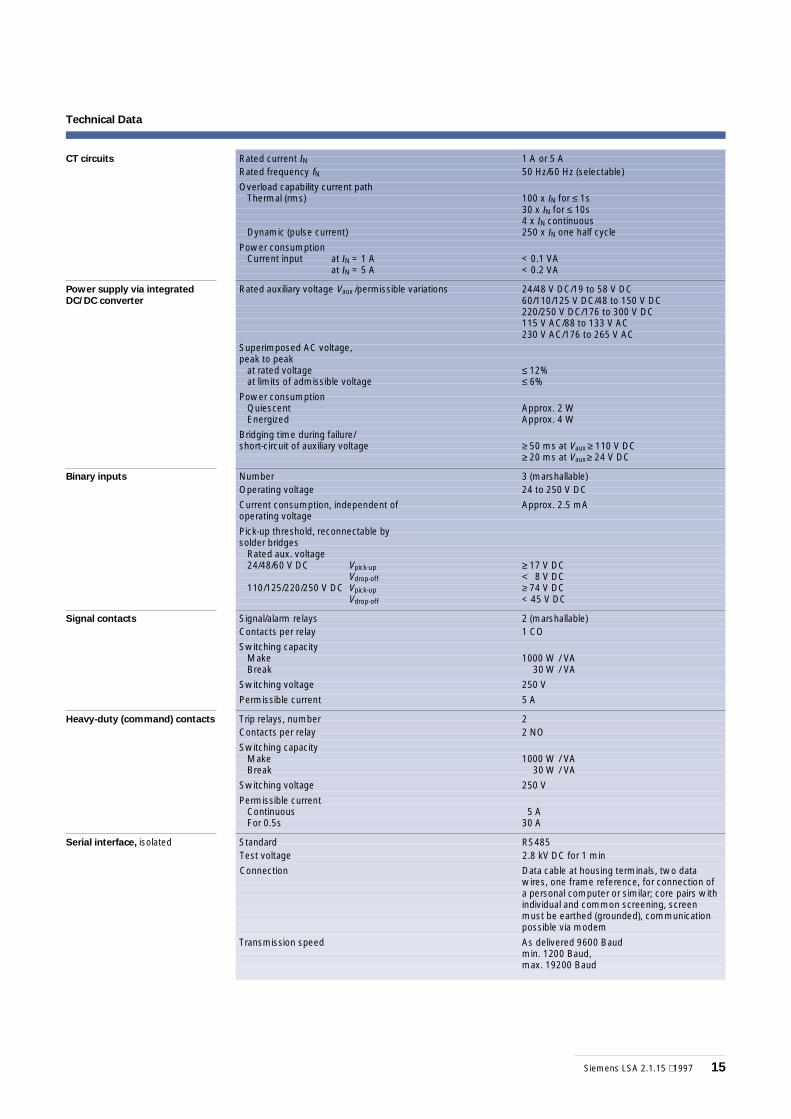
Technical Data
CT circuits Rated current IN 1 A or 5 ARated frequency fN 50 Hz/60 Hz (selectable)
Overload capability current pathThermal (rms)
Dynamic (pulse current)
100 x IN for ≤ 1s30 x IN for ≤ 10s4 x IN continuous250 x IN one half cycle
Power consumptionCurrent input at IN = 1 A
at IN = 5 A< 0.1 VA< 0.2 VA
Power supply via integrated
DC/DC converter
Rated auxiliary voltage Vaux /permissible variations 24/48 V DC/19 to 58 V DC60/110/125 V DC/48 to 150 V DC220/250 V DC/176 to 300 V DC115 V AC/88 to 133 V AC230 V AC/176 to 265 V AC
Superimposed AC voltage,peak to peak
at rated voltageat limits of admissible voltage
≤ 12%≤ 6%
Power consumptionQuiescentEnergized
Approx. 2 WApprox. 4 W
Bridging time during failure/short-circuit of auxiliary voltage ≥ 50 ms at Vaux ≥ 110 V DC
≥ 20 ms at Vaux≥ 24 V DC
Binary inputs Number 3 (marshallable)Operating voltage 24 to 250 V DC
Current consumption, independent ofoperating voltage
Approx. 2.5 mA
Pick-up threshold, reconnectable bysolder bridges
Rated aux. voltage24/48/60 V DC Vpick-up
Vdrop-off110/125/220/250 V DC Vpick-up
Vdrop-off
≥ 17 V DC< 8 V DC≥ 74 V DC< 45 V DC
Signal contacts Signal/alarm relays 2 (marshallable)Contacts per relay 1 CO
Switching capacityMakeBreak
1000 W / VA30 W / VA
Switching voltage 250 V
Permissible current 5 A
Heavy-duty (command) contacts Trip relays, number 2Contacts per relay 2 NO
Switching capacityMakeBreak
1000 W / VA30 W / VA
Switching voltage 250 V
Permissible currentContinuousFor 0.5s
5 A30 A
Serial interface, isolated Standard RS485Test voltage 2.8 kV DC for 1 min
Connection Data cable at housing terminals, two datawires, one frame reference, for connection ofa personal computer or similar; core pairs withindividual and common screening, screenmust be earthed (grounded), communicationpossible via modem
Transmission speed As delivered 9600 Baudmin. 1200 Baud,max. 19200 Baud
SIPROTEC 7SJ600 (Version V2.1)Numerical Overcurrent, Motor and Overload Relay
16 Siemens LSA 2.1.15 ⋅ 1997
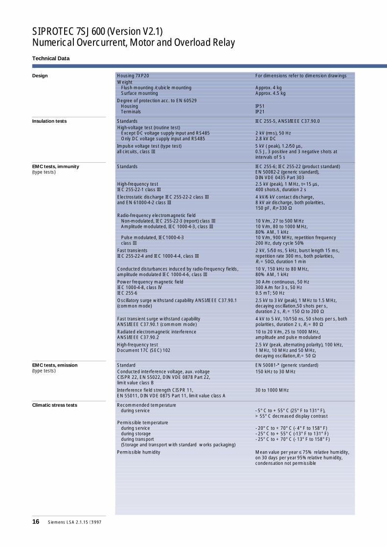
Technical Data
Design Housing 7XP20 For dimensions refer to dimension drawingsWeight
Flush mounting /cubicle mountingSurface mounting
Approx. 4 kgApprox. 4.5 kg
Degree of protection acc. to EN 60529HousingTerminals
IP51IP21
Insulation tests Standards IEC 255-5, ANSI/IEEE C37.90.0High-voltage test (routine test)
Except DC voltage supply input and RS485Only DC voltage supply input and RS485
2 kV (rms), 50 Hz2.8 kV DC
Impulse voltage test (type test)all circuits, class III
5 kV ( peak), 1.2/50 µs,0.5 J, 3 positive and 3 negative shots atintervals of 5 s
EMC tests, immunity(type tests)
Standards IEC 255-6; IEC 255-22 (product standard)EN 50082-2 (generic standard),DIN VDE 0435 Part 303
High-frequency testIEC 255-22-1 class III
2.5 kV (peak), 1 MHz, τ=15 µs,400 shots/s, duration 2 s
Electrostatic discharge IEC 255-22-2 class IIIand EN 61000-4-2 class III
4 kV/6 kV contact discharge,8 kV air discharge, both polarities,150 pF, Ri=330 Ω
Radio-frequency electromagnetic fieldNon-modulated, IEC 255-22-3 (report) class IIIAmplitude modulated, IEC 1000-4-3, class III
Pulse modulated, IEC1000-4-3class III
10 V/m, 27 to 500 MHz10 V/m, 80 to 1000 MHz,80% AM, 1 kHz10 V/m, 900 MHz, repetition frequency200 Hz, duty cycle 50%
Fast transientsIEC 255-22-4 and IEC 1000-4-4, class III
2 kV, 5/50 ns, 5 kHz, burst length 15 ms,repetition rate 300 ms, both polarities,Ri = 50Ω, duration 1 min
Conducted disturbances induced by radio-frequency fields,amplitude modulated IEC 1000-4-6, class III
10 V, 150 kHz to 80 MHz,80% AM, 1 kHz
Power frequency magnetic fieldIEC 1000-4-8, class IVIEC 255-6
30 A/m continuous, 50 Hz300 A/m for 3 s, 50 Hz0.5 mT; 50 Hz
Oscillatory surge withstand capability ANSI/IEEE C37.90.1(common mode)
2.5 kV to 3 kV (peak), 1 MHz to 1.5 MHz,decaying oscillation,50 shots per s,duration 2 s, Ri = 150 Ω to 200 Ω
Fast transient surge withstand capabilityANSI/IEEE C37.90.1 (commom mode)
4 kV to 5 kV, 10/150 ns, 50 shots per s, bothpolarities, duration 2 s, Ri = 80 Ω
Radiated electromagnetic interferenceANSI/IEEE C37.90.2
10 to 20 V/m, 25 to 1000 MHz,amplitude and pulse modulated
High-frequency testDocument 17C (SEC) 102
2.5 kV (peak, alternating polarity), 100 kHz,1 MHz, 10 MHz and 50 MHz,decaying oscillation,Ri = 50 Ω
EMC tests, emission
(type tests)Standard EN 50081-* (generic standard)Conducted interference voltage, aux. voltageCISPR 22, EN 55022, DIN VDE 0878 Part 22,limit value class B
150 kHz to 30 MHz
Interference field strength CISPR 11,EN 55011, DIN VDE 0875 Part 11, limit value class A
30 to 1000 MHz
Climatic stress tests Recommended temperatureduring service - 5° C to + 55° C (25° F to 131° F),
> 55° C decreased display contrastPermissible temperature
during serviceduring storageduring transport(Storage and transport with standard works packaging)
- 20° C to + 70° C (- 4° F to 158° F)- 25° C to + 55° C (-13° F to 131° F)- 25° C to + 70° C (- 13° F to 158° F)
Permissible humidity Mean value per year ≤ 75% relative humidity,on 30 days per year 95%relative humidity,condensation not permissible
Siemens LSA 2.1.15 ⋅ 1997 17
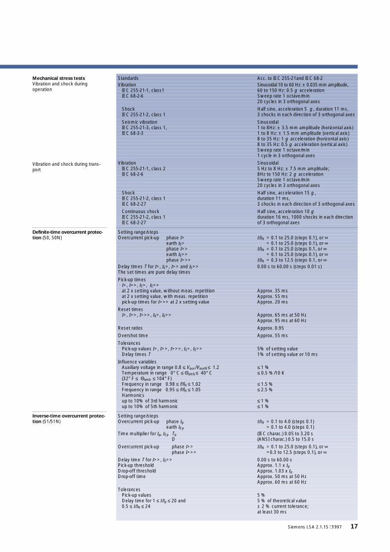
Mechanical stress tests
Vibration and shock duringoperation
Standards Acc. to IEC 255-21and IEC 68-2Vibration
IEC 255-21-1, class1IEC 68-2-6
Sinusoidal 10 to 60 Hz: ± 0.035 mm amplitude,60 to 150 Hz: 0.5 g accelerationSweep rate 1 octave/min20 cycles in 3 orthogonal axes
ShockIEC 255-21-2, class 1
Half sine, acceleration 5 g , duration 11 ms,3 shocks in each direction of 3 orthogonal axes
Seismic vibrationIEC 255-21-3, class 1,IEC 68-3-3
Sinusoidal1 to 8Hz: ± 3.5 mm amplitude (horizontal axis)1 to 8 Hz: ± 1.5 mm amplitude (vertical axis)8 to 35 Hz: 1 g acceleration (horizontal axis)8 to 35 Hz: 0.5 g acceleration (vertical axis)Sweep rate 1 octave/min1 cycle in 3 orthogonal axes
Vibration and shock during trans-port
VibrationIEC 255-21-1, class 2IEC 68-2-6
Sinusoidal5 Hz to 8 Hz: ± 7.5 mm amplitude;8Hz to 150 Hz: 2 g accelerationSweep rate 1 octave/min20 cycles in 3 orthogonal axes
ShockIEC 255-21-2, class 1IEC 68-2-27
Half sine, acceleration 15 g ,duration 11 ms,3 shocks in each direction of 3 orthogonal axes
Continuous shockIEC 255-21-2, class 1IEC 68-2-27
Half sine, acceleration 10 gduration 16 ms, 1000 shocks in each directionof 3 orthogonal axes
Definite-time overcurrent protec-
tion (50, 50N)Setting range/stepsOvercurrent pick-up phase I>
earth IE>phase I>>earth IE>>phase I>>>
I/IN = 0.1 to 25.0 (steps 0.1), or ∞= 0.1 to 25.0 (steps 0.1), or ∞
I/IN = 0.1 to 25.0 (steps 0.1, or ∞= 0.1 to 25.0 (steps 0.1), or ∞
I/IN = 0.3 to 12.5 (steps 0.1, or ∞Delay times T for I>, IE>, I>> and IE>>The set times are pure delay times
0.00 s to 60.00 s (steps 0.01 s)
Pick-up timesI>, I>>, IE>, IE>>at 2 x setting value, without meas. repetitionat 2 x setting value, with meas. repetitionpick-up times for I>>> at 2 x setting value
Approx. 35 msApprox. 55 msApprox. 20 ms
Reset timesI>, I>>, I>>>, IE>, IE>> Approx. 65 ms at 50 Hz
Approx. 95 ms at 60 Hz
Reset ratios Approx. 0.95
Overshot time Approx. 55 ms
TolerancesPick-up values I>, I>>, I>>>, IE>, IE>>Delay times T
5% of setting value1% of setting value or 10 ms
Influence variablesAuxiliary voltage in range 0.8 ≤ Vaux/VauxN≤ 1.2Temperature in range 0° C ≤ Θamb≤ 40° C(32° F ≤ Θamb ≤ 104° F)Frequency in range 0.98 ≤ f/fN ≤ 1.02Frequency in range 0.95 ≤ f/fN ≤ 1.05Harmonicsup to 10% of 3rd harmonicup to 10% of 5th harmonic
≤ 1 %≤ 0.5 %/10 K
≤ 1.5 %≤ 2.5 %
≤ 1 %≤ 1 %
Inverse-time overcurrent protec-
tion (51/51N)Setting range/stepsOvercurrent pick-up phase Ip
earth IEp
I/IN = 0.1 to 4.0 (steps 0.1)= 0.1 to 4.0 (steps 0.1)
Time multiplier for Ip, IEp TpD
(IEC charac.) 0.05 to 3.20 s(ANSI charac.) 0.5 to 15.0 s
Overcurrent pick-up phase I>>phase I>>>
I/IN = 0.1 to 25.0 (steps 0.1), or ∞=0.3 to 12.5 (steps 0.1), or ∞
Delay time T for I>>, IE>>Pick-up thresholdDrop-off thresholdDrop-off time
0.00 s to 60.00 sApprox. 1.1 x IpApprox. 1.03 x IpApprox. 50 ms at 50 HzApprox. 60 ms at 60 Hz
TolerancesPick-up valuesDelay time for 1 ≤ I/Ip ≤ 20 and0.5 ≤ I/IN ≤ 24
5 %5 % of theoretical value± 2 % current tolerance;at least 30 ms
SIPROTEC 7SJ600 (Version V2.1)Numerical Overcurrent, Motor and Overload Relay
18 Siemens LSA 2.1.15 ⋅ 1997
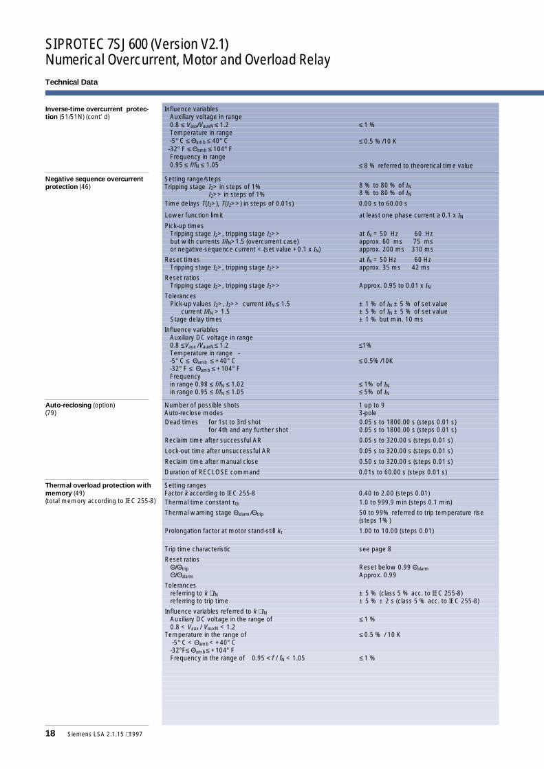
Technical Data
Inverse-time overcurrent protec-
tion (51/51N) (cont’ d)Influence variables
Auxiliary voltage in range0.8 ≤ Vaux/VauxN≤ 1.2Temperature in range-5° C ≤ Θamb ≤ 40° C-32° F ≤ Θamb ≤ 104° FFrequency in range0.95 ≤ f/fN ≤ 1.05
≤ 1 %
≤ 0.5 %/10 K
≤ 8 % referred to theoretical time value
Negative sequence overcurrent
protection (46)Setting range/stepsTripping stage I2> in steps of 1%
I2>> in steps of 1%8 % to 80 % of IN8 % to 80 % of IN
Time delays T(I2>), T(I2>>) in steps of 0.01s) 0.00 s to 60.00 s
Lower function limit at least one phase current ≥ 0.1 x IN
Pick-up timesTripping stage I2>, tripping stage I2>>but with currents I/IN>1.5 (overcurrent case)or negative-sequence current < (set value +0.1 x IN)
at fN = 50 Hz 60 Hzapprox. 60 ms 75 msapprox. 200 ms 310 ms
Reset timesTripping stage I2>, tripping stage I2>>
at fN = 50 Hz 60 Hzapprox. 35 ms 42 ms
Reset ratiosTripping stage I2>, tripping stage I2>> Approx. 0.95 to 0.01 x IN
TolerancesPick-up values I2>, I2>> current I/IN ≤ 1.5
current I/IN > 1.5Stage delay times
± 1 % of IN ± 5 % of set value± 5 % of IN ± 5 % of set value± 1 % but min. 10 ms
Influence variablesAuxiliary DC voltage in range0.8 ≤Vaux /VauxN≤ 1.2Temperature in range --5° C ≤ Θamb ≤ +40° C-32° F ≤ Θamb ≤ +104° FFrequencyin range 0.98 ≤ f/fN ≤ 1.02in range 0.95 ≤ f/fN ≤ 1.05
≤1%
≤ 0.5%/10K
≤ 1% of IN≤ 5% of IN
Auto-reclosing (option)(79)
Number of possible shotsAuto-reclose modes
1 up to 93-pole
Dead times for 1st to 3rd shotfor 4th and any further shot
0.05 s to 1800.00 s (steps 0.01 s)0.05 s to 1800.00 s (steps 0.01 s)
Reclaim time after successful AR 0.05 s to 320.00 s (steps 0.01 s)
Lock-out time after unsuccessful AR 0.05 s to 320.00 s (steps 0.01 s)
Reclaim time after manual close 0.50 s to 320.00 s (steps 0.01 s)
Duration of RECLOSE command 0.01s to 60.00 s (steps 0.01 s)
Thermal overload protection with
memory (49)(total memory according to IEC 255-8)
Setting rangesFactor k according to IEC 255-8 0.40 to 2.00 (steps 0.01)Thermal time constant τth 1.0 to 999.9 min (steps 0.1 min)
Thermal warning stage Θalarm/Θtrip 50 to 99% referred to trip temperature rise(steps 1%)
Prolongation factor at motor stand-still kτ 1.00 to 10.00 (steps 0.01)
Trip time characteristic see page 8
Reset ratiosΘ/ΘtripΘ/Θalarm
Reset below 0.99 ΘalarmApprox. 0.99
Tolerancesreferring to k ⋅ INreferring to trip time
± 5 % (class 5 % acc. to IEC 255-8)± 5 % ± 2 s (class 5 % acc. to IEC 255-8)
Influence variables referred to k ⋅ INAuxiliary DC voltage in the range of0.8 < Vaux / VauxN < 1.2
Temperature in the range of-5° C < Θamb< +40° C-32°F≤ Θamb≤ +104° FFrequency in the range of 0.95 < f / fN < 1.05
≤ 1 %
≤ 0.5 % / 10 K
≤ 1 %
Siemens LSA 2.1.15 ⋅ 1997 19
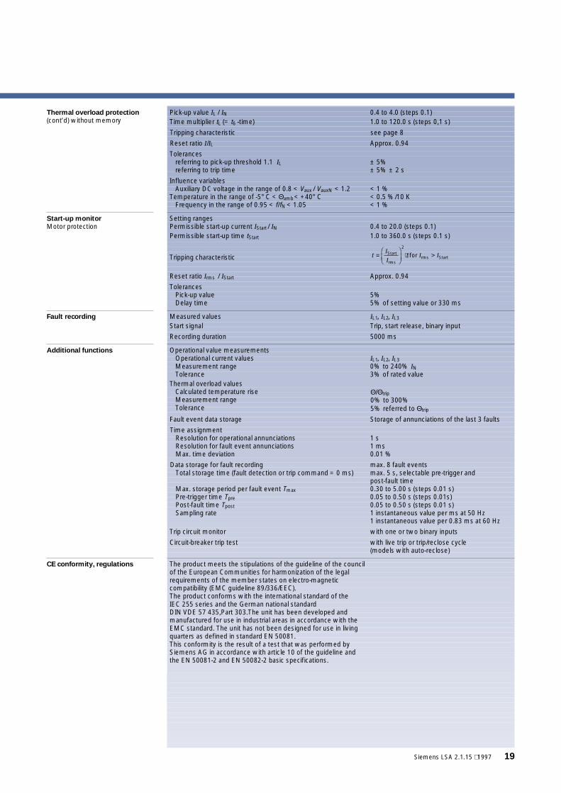
Thermal overload protection
(cont’d) without memoryPick-up value IL / IN 0.4 to 4.0 (steps 0.1)Time multiplier tL (= t6 -time) 1.0 to 120.0 s (steps 0,1 s)
Tripping characteristic see page 8
Reset ratio I/IL Approx. 0.94
Tolerancesreferring to pick-up threshold 1.1 ILreferring to trip time
± 5%± 5% ± 2 s
Influence variablesAuxiliary DC voltage in the range of 0.8 < Vaux / VauxN < 1.2
Temperature in the range of -5° C < Θamb< +40° CFrequency in the range of 0.95 < f/fN < 1.05
< 1 %< 0.5 %/10 K< 1 %
Start-up monitor
Motor protectionSetting rangesPermissible start-up current IStart / IN 0.4 to 20.0 (steps 0.1)Permissible start-up time tStart 1.0 to 360.0 s (steps 0.1 s)
Tripping characteristic
Reset ratio Irms / IStart Approx. 0.94
TolerancesPick-up valueDelay time
5%5% of setting value or 330 ms
Fault recording Measured values IL1, IL2, IL3
Start signal Trip, start release, binary input
Recording duration 5000 ms
Additional functions Operational value measurementsOperational current valuesMeasurement rangeTolerance
IL1, IL2, IL30% to 240% IN3% of rated value
Thermal overload valuesCalculated temperature riseMeasurement rangeTolerance
Θ/Θtrip0% to 300%5% referred to Θtrip
Fault event data storage Storage of annunciations of the last 3 faults
Time assignmentResolution for operational annunciationsResolution for fault event annunciationsMax. time deviation
1 s1 ms0.01 %
Data storage for fault recordingTotal storage time (fault detection or trip command = 0 ms)
Max. storage period per fault event TmaxPre-trigger time TprePost-fault time TpostSampling rate
max. 8 fault eventsmax. 5 s, selectable pre-trigger andpost-fault time0.30 to 5.00 s (steps 0.01 s)0.05 to 0.50 s (steps 0.01s)0.05 to 0.50 s (steps 0.01 s)1 instantaneous value per ms at 50 Hz1 instantaneous value per 0.83 ms at 60 Hz
Trip circuit monitor with one or two binary inputs
Circuit-breaker trip test with live trip or trip/reclose cycle(models with auto-reclose)
CE conformity, regulations The product meets the stipulations of the guideline of the councilof the European Communities for harmonization of the legalrequirements of the member states on electro-magneticcompatibility (EMC guideline 89/336/EEC).The product conforms with the international standard of theIEC 255 series and the German national standardDIN VDE 57 435,Part 303.The unit has been developed andmanufactured for use in industrial areas in accordance with theEMC standard. The unit has not been designed for use in livingquarters as defined in standard EN 50081.This conformity is the result of a test that was performed bySiemens AG in accordance with article 10 of the guideline andthe EN 50081-2 and EN 50082-2 basic specifications.
t t=FHG
IKJ
⋅ >I
II IStart
rms
2
rms Startfor
SIPROTEC 7SJ600 (Version V2.1)Numerical Overcurrent, Motor and Overload Relay
20 Siemens LSA 2.1.15 ⋅ 1997
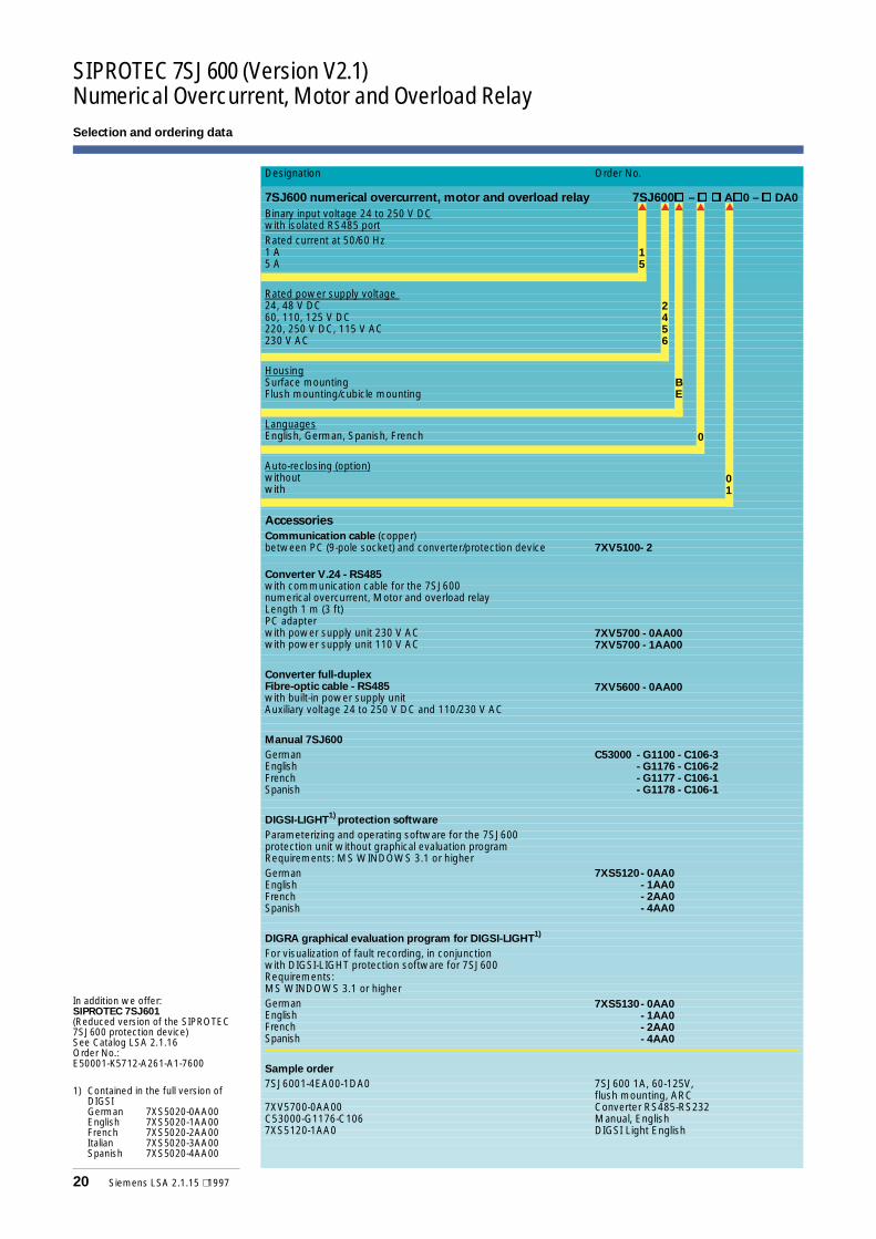
Selection and ordering data
In addition we offer:SIPROTEC 7SJ601(Reduced version of the SIPROTEC7SJ600 protection device)See Catalog LSA 2.1.16Order No.:E50001-K5712-A261-A1-7600
1) Contained in the full version ofDIGSIGerman 7XS5020-0AA00English 7XS5020-1AA00French 7XS5020-2AA00Italian 7XS5020-3AA00Spanish 7XS5020-4AA00
Designation Order No.
7SJ600 numerical overcurrent, motor and overload relay 7SJ600¨ –¨¨ A¨0 –¨ DA0
Binary input voltage 24 to 250 V DCwith isolated RS485 portRated current at 50/60 Hz1 A5 A
Rated power supply voltage24, 48 V DC60, 110, 125 V DC220, 250 V DC, 115 V AC230 V AC
HousingSurface mountingFlush mounting/cubicle mounting
LanguagesEnglish, German, Spanish, French
Auto-reclosing (option)withoutwith
Accessories
Communication cable (copper)between PC (9-pole socket) and converter/protection device 7XV5100- 2
Converter V.24 - RS485with communication cable for the 7SJ600numerical overcurrent, Motor and overload relayLength 1 m (3 ft)PC adapterwith power supply unit 230 V ACwith power supply unit 110 V AC
Converter full-duplexFibre-optic cable - RS485with built-in power supply unitAuxiliary voltage 24 to 250 V DC and 110/230 V AC
Manual 7SJ600
GermanEnglishFrenchSpanish
DIGSI-LIGHT1)
protection software
Parameterizing and operating software for the 7SJ600protection unit without graphical evaluation programRequirements: MS WINDOWS 3.1 or higherGermanEnglishFrenchSpanish
DIGRA graphical evaluation program for DIGSI-LIGHT1)
For visualization of fault recording, in conjunctionwith DIGSI-LIGHT protection software for 7SJ600Requirements:MS WINDOWS 3.1 or higherGermanEnglishFrenchSpanish
Sample order
7SJ6001-4EA00-1DA0 7SJ600 1A, 60-125V,flush mounting, ARC
7XV5700-0AA00 Converter RS485-RS232C53000-G1176-C106 Manual, English7XS5120-1AA0 DIGSI Light English
7XS5130- 0AA0- 1AA0- 2AA0- 4AA0
7XS5120- 0AA0- 1AA0- 2AA0- 4AA0
C53000 - G1100 - C106-3- G1176 - C106-2- G1177 - C106-1- G1178 - C106-1
7XV5600 - 0AA00
7XV5700 - 0AA007XV5700 - 1AA00
15
2456
BE
0
01
Siemens LSA 2.1.15 ⋅ 1997 21
Circuit diagram
Vers
ion
fors
urfa
ce-m
ount
ing
Vers
ion
forf
lush
/cub
icle
mou
ntin
g
Trip
rela
y
Trip
ping
ofde
f.-tim
eov
ercu
r.pr
ot.I
>>
(pha
ses)
Trip
ping
ofde
f.-tim
eov
ercu
r.pr
ot.I
>(p
hase
s)
Trip
ping
ofde
f.-tim
eov
ercu
r.pr
ot.I
>(g
roun
d)
ALA
RM
cont
acts
Rea
dy(“
Life
-con
tact
”)
Pic
kup
(gro
unde
d)(g
roun
ded)
INPU
T
Res
etLE
Ddi
spla
ys
Blo
cktim
eov
ercu
rren
tpro
tect
ion
Man
ualC
lose
Pow
ersu
pply
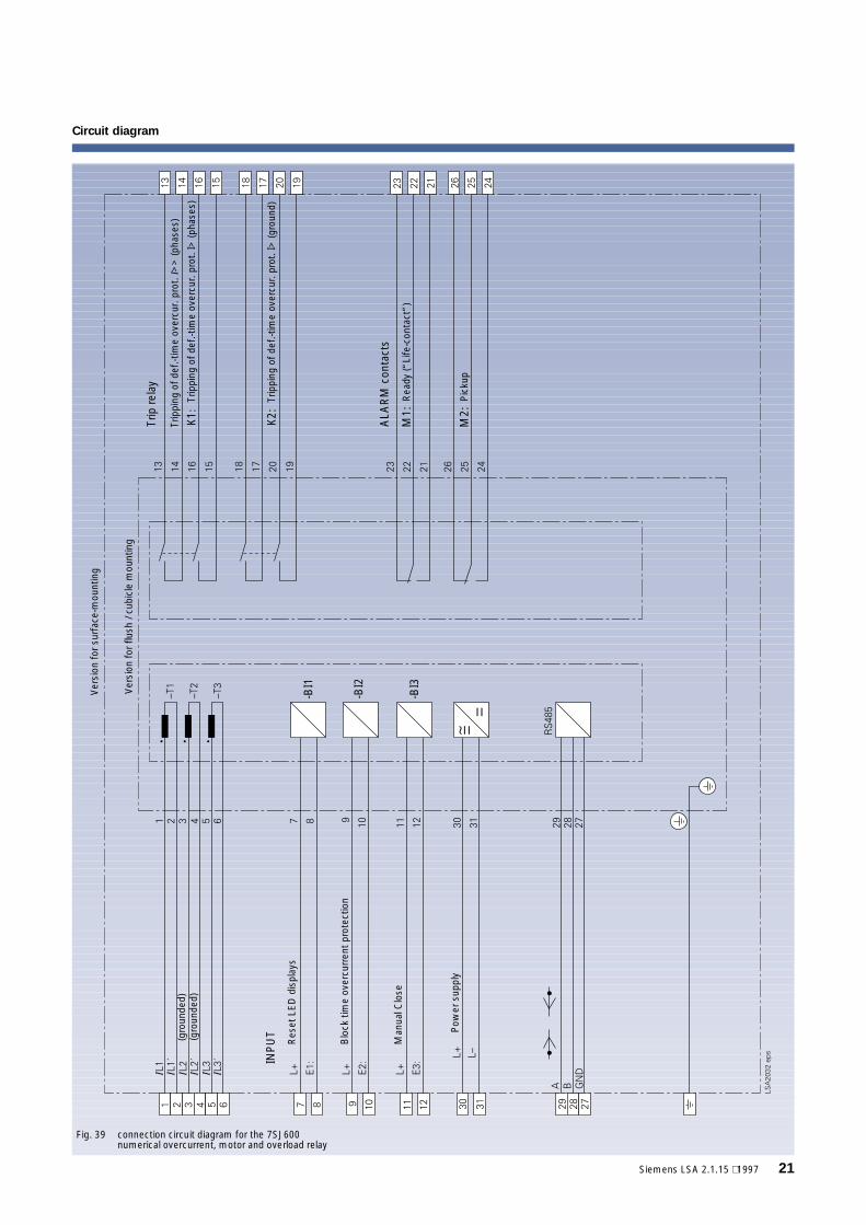
Fig. 39 connection circuit diagram for the 7SJ600numerical overcurrent, motor and overload relay
K1:
-BI1
-BI3
K2:
M1:
M2:
-BI2
SIPROTEC 7SJ600 (Version V2.1)Numerical Overcurrent, Motor and Overload Relay
22 Siemens LSA 2.1.15 ⋅ 1997
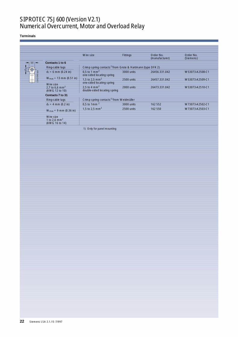
Terminals
Wire size Fittings Order No.(manufacturer)
Order No.(Siemens)
Contacts 1 to 6
Ring-cable lugs Crimp spring contacts1)from Grote & Hartmann (type DFK 2)
d1 = 6 mm (0.24 in)
Wmax.= 13 mm (0.51 in)
Wire size2,7 to 6,6 mm2
(AWG 12 to 10)
0,5 to 1 mm2
one-sided locating spring3000 units 26456.331.042 W53073-A2508-C1
1,5 to 2,5 mm2
one-sided locating spring2500 units 26457.331.042 W53073-A2509-C1
2,5 to 4 mm2
double-sided locating spring2000 units 26473.331.042 W53073-A2510-C1
Contacts 7 to 31
Ring-cable lugs Crimp spring contacts1) from Weidmüller
d1 = 4 mm (0.2 in)
Wmax.= 9 mm (0.36 in)
Wire size1 to 2,6 mm2
(AWG 16 to 14)
0,5 to 1mm 2 3000 units 162 552 W73073-A2502-C1
1,5 to 2,5 mm2 2500 units 162 550 W73073-A2503-C1
1) Only for panel mounting
Siemens LSA 2.1.15 ⋅ 1997 23
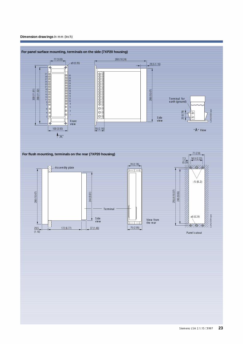
Dimension drawings in mm (inch)
Frontview
Sideview
Terminal forearth (ground)
“A” View
Sideview
Terminal
View fromthe rear
Panel cutout
∅5 (0.2)
Assembly plate
For panel surface mounting, terminals on the side (7XP20 housing)
For flush mounting, terminals on the rear (7XP20 housing)
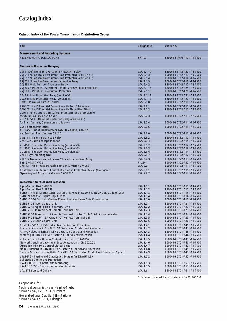
Catalog Index
Title Designation Order No.
Measurement and Recording Systems
Fault Recorder OSCILLOSTORE SR 10.1 E50001-K4010-A101-A1-7600
Numerical Protective Relaying
7SJ41 Definite-Time Overcurrent Protection Relay LSA 2.1.10 E50001-K5712-A201-A2-76007SJ511 Numerical Overcurrent-Time Protection (Version V3) LSA 2.1.3 E50001-K5712-A131-A3-76007SJ512 Numerical Overcurrent-Time Protection (Version V3) LSA 2.1.4 E50001-K5712-A141-A3-76007SJ531 Numerical Overcurrent Protection Relay LSA 2.1.9 E50001-K5712-A191-A3-76007SJ551 Multi-Function Protection Relay LSA 2.4.2 E50001-K5742-A121-A2-76007SJ600 SIPROTEC Overcurrent, Motor and Overload Protection LSA 2.1.15 E50001-K5712-A251-A2-76007SJ601 SIPROTEC Overcurrent Protection LSA 2.1.16 E50001-K5712-A261-A1-7600
7SA511 Line Protection Relay (Version V3) LSA 2.1.11 E50001-K5712-A211-A2-76007SA513 Line Protection Relay (Version V3) LSA 2.1.12 E50001-K5712-A221-A1-76003VU13 Miniature Circuit-Breaker LSA 2.1.8 E50001-K5712-A181-A1-7600
7SD502 Line Differential Protection with Two Pilot Wires LSA 2.2.1 E50001-K5722-A111-A2-76007SD503 Line Differential Protection with Three Pilot Wires LSA 2.2.2 E50001-K5722-A121-A2-76007SD511/512 Current Comparison Protection Relay (Version V3)for Overhead Lines and Cables LSA 2.2.3 E50001-K5722-A131-A2-76007UT512/513 Differential Protection Relay (Version V3)for Transformers, Generators and Motors LSA 2.2.4 E50001-K5722-A141-A2-7600
7SS5 Station Protection LSA 2.2.5 E50001-K5722-A151-A2-7600Auxiliary Current Transformers 4AM50, 4AM51, 4AM52and Isolating Transformers 7XR95 LSA 2.2.6 E50001-K5722-A161-A1-7600
7SN71 Transient Earth-Fault Relay LSA 2.3.2 E50001-K5732-A121-A1-76007VC1637 Earth-Leakage Monitor LSA 2.3.4 E50001-K5732-A141-A1-7600
7UM511 Generator Protection Relay (Version V3) LSA 2.5.2 E50001-K5752-A121-A2-76007UM512 Generator Protection Relay (Version V3) LSA 2.5.3 E50001-K5752-A131-A2-76007UM515 Generator Protection Relay (Version V3) LSA 2.5.4 E50001-K5752-A141-A2-76007VE51 Synchronizing Unit LSA 2.5.7 E50001-K5752-A171-A1-7600
7VK512 Numerical Auto-Reclose/Check-Synchronism Relay LSA 2.7.3 E50001-K5772-A131-A1-7600Test Switch 7XV72 R 2.20 E50001-K4502-A301-A1-76007VP151 Three-Phase Portable Test Set (Omicron CMC56) LSA 2.6.1 E50001-K5762-A111-A2-7600
Centralized and Remote Control of Siemens Protection Relays (Overview)* LSA 2.8.1 E50001-K5782-A111-A1-7600Operating and Analysis Software DIGSI V3* LSA 2.8.2 E50001-K5782-A121-A1-7600
Substation Control and Protection
Input/Output Unit 6MB522 LSA 1.1.1 E50001-K5701-A111-A4-7600Input/Output Unit 6MB523 LSA 1.1.2 E50001-K5701-A121-A2-76006MB511/6MB512 Substation Master Unit 7SW511/7SW512 Relay Data Concentrator LSA 1.1.3 E50001-K5701-A131-A2-76006MB520/6MB521 Input/Output Units LSA 1.1.4 E50001-K5701-A141-A1-76006MB513/514 Compact Control Master Unit and Relay Data Concentrator LSA 1.1.6 E50001-K5701-A161-A1-7600
6MB5510 Station Control Unit LSA 1.2.1 E50001-K5701-A211-A2-76006MB552 Compact Remote Terminal Unit LSA 1.2.2 E50001-K5701-A221-A1-76006MB5530-0 Minicompact Remote Terminal Unit LSA 1.2.3 E50001-K5701-A231-A1-7600
6MB5530-1 Minicompact Remote Terminal Unit for Cable Shield Communication LSA 1.2.4 E50001-K5701-A241-A1-76006MB5540 SINAUT LSA COMPACT Remote Terminal Unit LSA 1.2.5 E50001-K5701-A251-A1-76006MB5515 Station Control Unit LSA 1.2.6 E50001-K5701-A261-A1-7600
Control in SINAUT LSA Substation Control and Protection LSA 1.4.1 E50001-K5701-A411-A1-7600Status Indications in SINAUT LSA Substation Control and Protection LSA 1.4.2 E50001-K5701-A421-A1-7600Analog Values in SINAUT LSA Substation Control and Protection LSA 1.4.3 E50001-K5701-A431-A1-7600Metering in SINAUT LSA Substation Control and Protection LSA 1.4.4 E50001-K5701-A441-A1-7600
Voltage Control with Input/Output Units 6MB520/6MB521 LSA 1.4.5 E50001-K5701-A451-A1-7600Network Synchronization with Input/Output Units 6MB520/521 LSA 1.4.6 E50001-K5701-A461-A1-7600Operation with Two Control Master Units LSA 1.4.7 E50001-K5701-A471-A1-7600Node Functions in SINAUT LSA Substation Control and Protection LSA 1.4.8 E50001-K5701-A481-A1-7600System Management with the SINAUT LSA Substation Control and Protection System LSA 1.4.9 E50001-K5701-A491-A1-7600
LSADIAG - Testing and Diagnostics System for SINAUT LSA LSA 1.5.2 E50001-K5701-A521-A1-7600Substation Control and ProtectionLSACONTROL - Control and Monitoring LSA 1.5.3 E50001-K5701-A531-A1-7600LSAPROCESS - Process Information Analysis LSA 1.5.5 E50001-K5701-A551-A1-7600
LSA 678 Standard Cubicle LSA 1.6.1 E50001-K5701-A611-A1-7600
* Information on additional equipment for 7SJ600/601
Catalog Index of the Power Transmission Distribution Group
Responsible forTechnical contents: Hans Heining-TriebsSiemens AG, EV S V13, NürnbergGeneral editing: Claudia Kühn-SutionoSiemens AG EV BK T, Erlangen
24 Siemens LSA 2.1.15 ⋅ 1997
Conditions of Sale and Delivery ⋅ Export RegulationsTrademarks ⋅ DimensionsConditions of Sale and Delivery
Export Regulations Dimensions
Subject to theGeneral Conditions of Supplyand Deliveryfor Products and Services ofthe Electrical and ElectronicIndustry and to any otherconditions agreed upon withthe recipients of catalogs.
The technical data, dimensionsand weights are subject tochange unless otherwise statedon the individual pages of thiscatalog.The illustrations are forreference only.We reserve the right to adjustthe prices and shall charge theprice applying on the date ofdelivery. En 1.91a
In accordance with the presentprovisions of the German Ex-port List and the US CommercialControl List, export licences arenot required for the productslisted in this catalog.
An export licence may how-ever be required due to country-specific application and finaldestination of the products.Relevant are the export crite-ria stated in the delivery noteand in the invoice subject to apossible export and reexport li-cence.Subject to change without no-tice.
All dimensions in this catalogare given in mm (inch).
Trademarks
All product designations usedare trademarks or productnames of Siemens AG or ofothersuppliers.
Siemens online!
The Power Transmission and Distri-bution Group can also be found inthe Internet:http://www.ev.siemens.de
Order No.: E50001-K5712-A251-A2-7600
Printed in GermanyKG K 0697 6.0 24 EN321542 U0564

BereichEnergieübertragung und -verteilungGeschäftsgebiet SekundärsystemePostfach 4806D-90026 Nürnberg
Siemens Aktiengesellschaft Order No.: E50001-K5712-A251-A2-7600
Your Siemens representative