siprotec compact overcurrent protection 7sj81...
TRANSCRIPT
SIPROTEC CompactOvercurrent Protection 7SJ81 for Low-Power CT and VT Applications
Overcurrent Protection 7SJ81
3/2 SIPROTEC Compact Protection Devices 7SJ81 · Chapter 7SJ81 for the Edition 2.0 of the catalog E50001-K4403-A011-x-7600 · February 2012
for Low-Power CT and VT Applications
Page
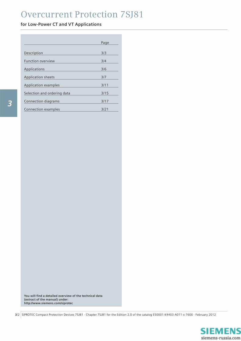
Description 3/3
Function overview 3/4
Applications 3 /6
Application sheets 3/ 7
Application examples 3/ 11
Selection and ordering data 3/15
Connection diagrams 3 / 17
Connection examples 3 / 21
You will fi nd a detailed overview of the technical data (extract of the manual) under: http://www.siemens.com/siprotec
3
Overcurrent Protection 7SJ81
3/3SIPROTEC Compact Protection Devices 7SJ81 · Chapter 7SJ81 for the Edition 2.0 of the catalog E50001-K4403-A011-x-7600 · February 2012
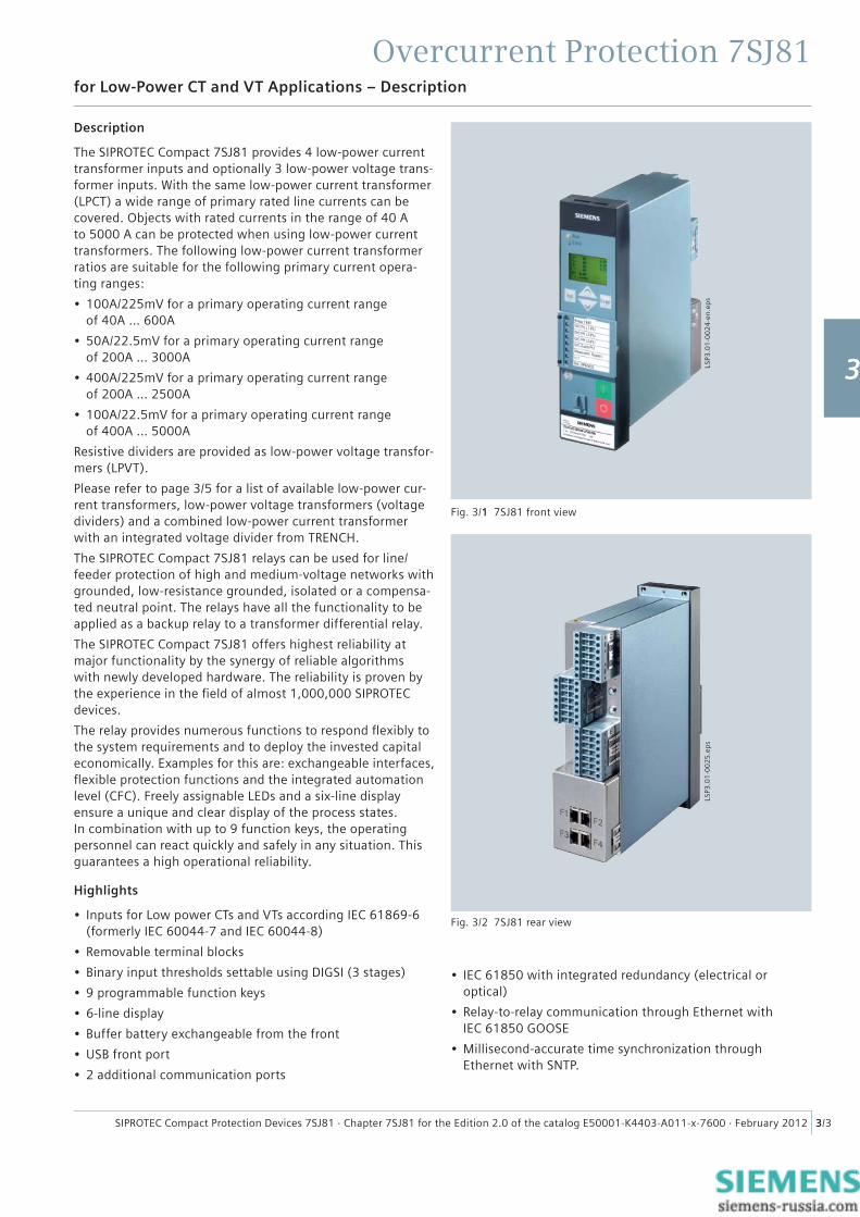
Fig. 3/1 7SJ81 front view
Description
The SIPROTEC Compact 7SJ81 provides 4 low-power current transformer inputs and optionally 3 low-power voltage trans-former inputs. With the same low-power current transformer (LPCT) a wide range of primary rated line currents can be covered. Objects with rated currents in the range of 40 A to 5000 A can be protected when using low-power current transformers. The following low-power current transformer ratios are suitable for the following primary current opera-ting ranges:
• 100A/225mV for a primary operating current range of 40A … 600A
• 50A/22.5mV for a primary operating current range of 200A … 3000A
• 400A/225mV for a primary operating current rangeof 200A … 2500A
• 100A/22.5mV for a primary operating current rangeof 400A … 5000A
Resistive dividers are provided as low-power voltage transfor-mers (LPVT).
Please refer to page 3/5 for a list of available low-power cur-rent transformers, low-power voltage transformers (voltage dividers) and a combined low-power current transformer with an integrated voltage divider from TRENCH.
The SIPROTEC Compact 7SJ81 relays can be used for line/ feeder protection of high and medium-voltage networks with grounded, low-resistance grounded, isolated or a compensa-ted neutral point. The relays have all the functionality to be applied as a backup relay to a transformer differential relay.
The SIPROTEC Compact 7SJ81 offers highest reliability at major functionality by the synergy of reliable algorithms with newly developed hardware. The reliability is proven by the experience in the fi eld of almost 1,000,000 SIPROTEC devices.
The relay provides numerous functions to respond fl exibly to the system requirements and to deploy the invested capital economically. Examples for this are: exchangeable interfaces, fl exible protection functions and the integrated automation level (CFC). Freely assignable LEDs and a six-line display ensure a unique and clear display of the process states. In combination with up to 9 function keys, the operating personnel can react quickly and safely in any situation. This guarantees a high operational reliability.
Highlights
• Inputs for Low power CTs and VTs according IEC 61869-6 (formerly IEC 60044-7 and IEC 60044-8)
• Removable terminal blocks
• Binary input thresholds settable using DIGSI (3 stages)
• 9 programmable function keys
• 6-line display
• Buffer battery exchangeable from the front
• USB front port
• 2 additional communication ports
for Low-Power CT and VT Applications – Description
LSP3
.01
-00
24
-en
.ep
sLS
P3.0
1-0
02
5.e
ps
• IEC 61850 with integrated redundancy (electrical or optical)
• Relay-to-relay communication through Ethernet with IEC 61850 GOOSE
• Millisecond-accurate time synchronization through Ethernet with SNTP.
Fig. 3/2 7SJ81 rear view
1
2
3
4
5
6
7
8
9
Overcurrent Protection 7SJ81
3/4 SIPROTEC Compact Protection Devices 7SJ81 · Chapter 7SJ81 for the Edition 2.0 of the catalog E50001-K4403-A011-x-7600 · February 2012
for Low-Power CT and VT Applications – Function overview
Control functions / programmable logic
• Commands for the ctrl. of CB, disconnect switches (isolators/isolating switches)
• Control through keyboard, binary inputs, DIGSI 4 or SCADA system
• User-defi ned PLC logic with CFC (e.g. interlocking).
Monitoring functions
• Operational measured values I, V, f• Energy metering values Wp, Wg
• Circuit-breaker wear monitoring
• Minimum and maximum values
• Trip circuit supervision (74TC)
• Fuse failure monitor
• 8 oscillographic fault records.
Communication interfaces
• System/service interface
– IEC 61850 – IEC 60870-5-103 – PROFIBUS-DP – DNP 3.0 – MODBUS RTU
• Ethernet interface for DIGSI 4
• USB front interface for DIGSI 4.
Hardware
• 4 current inputs
• 0/3 voltage inputs
• 3/7 binary inputs (thresholds confi gurable using software)
• 5/8 binary outputs (2 changeover / Form C contacts)
• 1 live-status contact
• Pluggable voltage terminals.
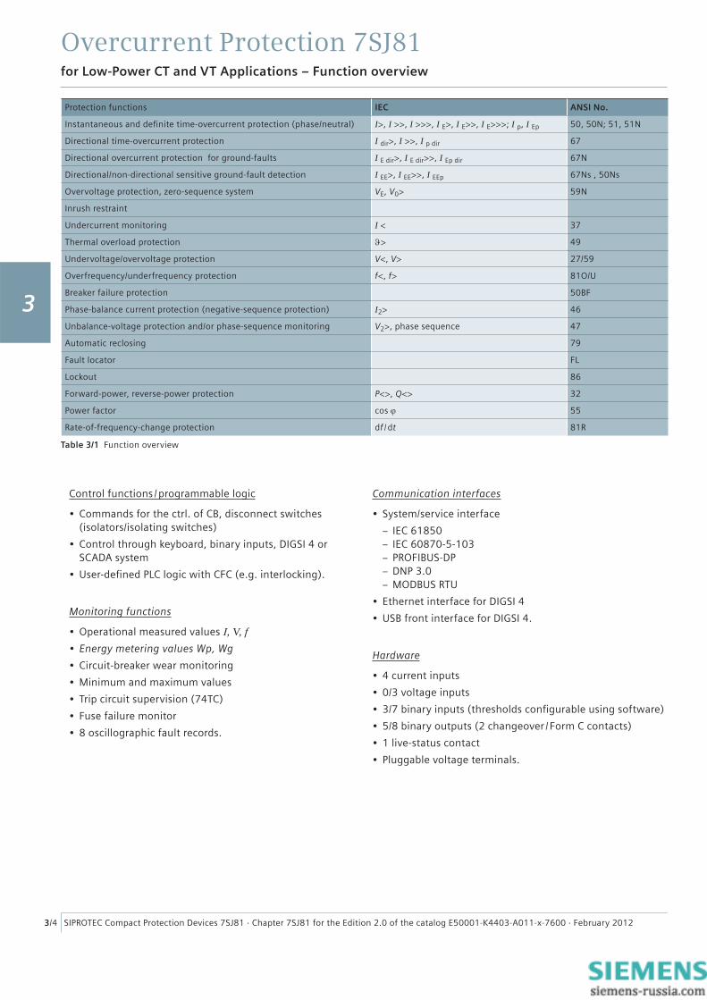
Table 3/1 Function overview
Protection functions IEC ANSI No.
Instantaneous and defi nite time-overcurrent protection (phase/neutral) I>, I >>, I >>>, I E>, I E>>, I E>>>; I p, I Ep 50, 50N; 51, 51N
Directional time-overcurrent protection I dir>, I >>, I p dir 67
Directional overcurrent protection for ground-faults I E dir>, I E dir>>, I Ep dir 67N
Directional/non-directional sensitive ground-fault detection I EE>, I EE>>, I EEp 67Ns , 50Ns
Overvoltage protection, zero-sequence system VE, V0> 59N
Inrush restraint
Undercurrent monitoring I < 37
Thermal overload protection ϑ> 49
Undervoltage/overvoltage protection V<, V> 27/59
Overfrequency/underfrequency protection f<, f> 81O/U
Breaker failure protection 50BF
Phase-balance current protection (negative-sequence protection) I2> 46
Unbalance-voltage protection and/or phase-sequence monitoring V2>, phase sequence 47
Automatic reclosing 79
Fault locator FL
Lockout 86
Forward-power, reverse-power protection P<>, Q<> 32
Power factor cos ϕ 55
Rate-of-frequency-change protection df / dt 81R
3
Overcurrent Protection 7SJ81
3/5SIPROTEC Compact Protection Devices 7SJ81 · Chapter 7SJ81 for the Edition 2.0 of the catalog E50001-K4403-A011-x-7600 · February 2012
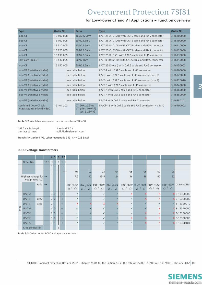
Type Order No. Ratio Type Order No.
lopo CT 16 100 008 100A/225mV LPCT 25-A (D120) with CAT.5 cable and RJ45 connector 3-16100000
lopo CT 16 100 005 50A/22.5mV LPCT 25-A (D120) with CAT.5 cable and RJ45 connector 3-16100000
lopo CT 16 110 005 50A/22.5mV LPCT 25-B (D108) with CAT.5 cable and RJ45 connector 3-16110000
lopo CT 16 120 005 50A/22.5mV LPCT 25-C (D300) with CAT.5 cable and RJ45 connector 3-16120000
lopo CT 16 130 005 50A/22.5mV LPCT 25-D (D55) with CAT.5 cable and RJ45 connector 3-16130000
split-core lopo CT 16 140 005 60A/7.07V LPCT K-60 (D120) with CAT.5 cable and RJ45 connector 3-16140000
lopo CT 16 150 005 50A/22.5mV LPCT 25-E (oval) with CAT.5 cable and RJ45 connector 3-16150003
lopo VT (resistive divider) see table below LPVT-A with CAT.5 cable and RJ45 connector 3-16300000
lopo VT (resistive divider) see table below LPVT-I with CAT.5 cable and RJ45 connector (size 2) 3-16320000
lopo VT (resistive divider) see table below LPVT-I with CAT.5 cable and RJ45 connector (size 3) 3-16320010
lopo VT (resistive divider) see table below LPVT-G with CAT.5 cable and RJ45 connector 3-16340000
lopo VT (resistive divider) see table below LPVT-P with CAT.5 cable and RJ45 connector 3-16360000
lopo VT (resistive divider) see table below LPVT-F with CAT.5 cable and RJ45 connector 3-16380000
lopo VT (resistive divider) see table below LPVT-S with CAT.5 cable and RJ45 connector 3-16380101
combined (lopo CT withintegrated resistive divider)
16 401 202 CT: 50A/22.5mVVT: prim: 10kV/√3 sec: 3.25V/√3
LPVCT-12 with CAT.5 cable and RJ45 connector; 4 x M12 3-16400002
Table 3/2 Available low-power transformers from TRENCH
CAT.5 cable length: Standard 6.5 mContact partner: [email protected]
Trench Switzerland AG, Lehenmattstraße 353, CH-4028 Basel
for Low-Power CT and VT Applications – Function overview
4 5 6 7 8
Order No.: 16 3 2
01 02 03 04 05 06 07 08
Highest voltage for equipment [kV]
→ 7.2 12 15.5 24 36 38 40 52
Ratio →
325.3
36 VkV
325.3
310 VkV
325.3
315 VkV
325.3
320 VkV
325.3
330 VkV
325.3
35.34 VkV
325.3
336 VkV
325.3
345 VkV Drawing No.
Typ
e
LPVT-A 0 0 → X X X X 3-16300000
LPVT-I size2 2 0 → X X X 3-16320000
LPVT-I size3 2 1 → X X X X 3-16320010
LPVT-G 4 0 → X X 3-16340000
LPVT-P 6 0 → X X X 3-16360000
LPVT-F 8 0 → X X X X 3-16380000
LPVT-S 8 1 → X X X 3-16380101
RJ45 connector 2
Table 3/3 Order no. for LOPO voltage transformers
LOPO Voltage Transformers
1
2
3
4
5
6
7
8
9
Overcurrent Protection 7SJ81
3/6 SIPROTEC Compact Protection Devices 7SJ81 · Chapter 7SJ81 for the Edition 2.0 of the catalog E50001-K4403-A011-x-7600 · February 2012
Busbar
50
Operational measured values
Breaker Failure ProtectionARBF
Fault recording
Automatic reclosing
CFC logic
Commands/Feedbacks
Local/remote control
Trip circuit supervision
Operation
Limits
Mean value
min/max-memory
Metered energy: as counting pulses
Fault LocatorEsc Enter
741Fn
8520
963.
Communication module
Lock out
Directional supplement
Additional Directional ground fault protection
V, f, P
Phase sequence monitoring
50N 46 49 37
50N 51N
79 AR
51 51N 50BF
BFI>, I>>, I>>> I-TOC
IN>, IN>>, IN>>>
IN-TOC
74TC
86
IN>, IN>>, IN>>> IN-TOC
RS232/485/FO/EthernetIEC 60870-5-103IEC 61850PROFIBUS-DPDNP 3.0MODBUS RTU
32 55 81R
I, V, P, Q, cos , f
FL 47
59N67Ns
df/dtcosP<>, Q<>
59 2781U/O
INs>, INs>>67Ns-TOC VN>
V<V>f<, f>
I2>InRush
BLK
I<
I2>
I<
I>, I>> I-TOC
IN>, IN>>, IN-TOC
Flexible protection functions
67 67N
52 AND
Unbalanced load protectionThermal overload protectionUndercurrent monitoring
>
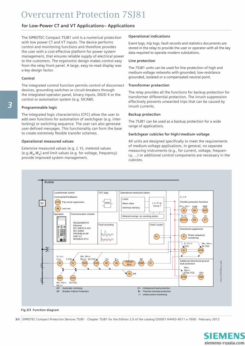
The SIPROTEC Compact 7SJ81 unit is a numerical protection with low power CT and VT inputs. The device performs control and monitoring functions and therefore provides the user with a cost-effective platform for power system management, that ensures reliable supply of electrical power to the customers. The ergonomic design makes control easy from the relay front panel. A large, easy-to-read display was a key design factor.
Control
The integrated control function permits control of disconnect devices, grounding switches or circuit-breakers through the integrated operator panel, binary inputs, DIGSI 4 or the control or automation system (e.g. SICAM).
Programmable logic
The integrated logic characteristics (CFC) allow the user to add own functions for automation of switchgear (e.g. inter-locking) or switching sequence. The user can also generate user-defi ned messages. This functionality can form the base to create extremely fl exible transfer schemes.
Operational measured values
Extensive measured values (e.g. I, V), metered values (e.g.Wp,Wq) and limit values (e.g. for voltage, frequency) provide improved system management.
Operational indications
Event logs, trip logs, fault records and statistics documents are stored in the relay to provide the user or operator with all the key data required to operate modern substations.
Line protection
The 7SJ81 units can be used for line protection of high and medium-voltage networks with grounded, low-resistance grounded, isolated or a compensated neutral point.
Transformer protection
The relay provides all the functions for backup protection for transformer differential protection. The inrush suppression effectively prevents unwanted trips that can be caused by inrush currents.
Backup protection
The 7SJ81 can be used as a backup protection for a wide range of applications.
Switchgear cubicles for high /medium voltage
All units are designed specifi cally to meet the requirements of medium-voltage applications. In general, no separate measuring instruments (e.g., for current, voltage, frequen-cy, …) or additional control components are necessary in the cubicles.
Fig.3/3 Function diagram
for Low-Power CT and VT Applications– Applications
Vis
io-L
SA4
78
3a-
us.
pd
f
3
Overcurrent Protection 7SJ81
3/7SIPROTEC Compact Protection Devices 7SJ81 · Chapter 7SJ81 for the Edition 2.0 of the catalog E50001-K4403-A011-x-7600 · February 2012
for Low-Power CT and VT Applications– Application sheets
Protection functions
Time-overcurrent protection (ANSI 50, 50N, 51, 51N)
This function is based on the phase-selective measurement of the three phase currents and the ground current (four transformers). Three defi nite-time overcurrent protection elements (DMT) are available both for the phase and the ground elements. The current threshold and the delay time can be set in a wide range.
Inverse-time overcurrent protection characteristics (IDMTL) can also be selected and activated.
Reset characteristics
Time coordination with electromechanical relays is made easy with the inclusion of the reset characteristics according to ANSI C37.112 and IEC 60255-3 / BS 142 standards. When using the reset characteristic (disk emulation), the reset pro-cess is initiated after the fault current has disappeared. This reset process corresponds to the reverse movement of the Ferraris disk of an electromechanical relay (disk emulation).
Available inverse-time characteristics
Characteristics acc. to IEC 60255-3 ANSI / IEEE
Inverse
Short inverse
Long inverse
Moderately inverse
Very inverse
Extremely inverse
Table 3/4 Available inverse-time characteristics
Inrush restraint
If second harmonic content is detected during the energi-zation of a transformer, the pickup of stages I >, I p, I >dir and I p dir is blocked.
Dynamic settings group switching
In addition to the static parameter changeover, the pickup thresholds and the tripping times for the directional and non-directional time-overcurrent protection functions can be changed over dynamically. As changeover criterion, the circuit-breaker position, the prepared auto-reclosure, or a binary input can be selected.
Directional comparison protection (cross-coupling)
It is used for selective instantaneous tripping of sections fed from two sources, i.e. without the disadvantage of time delays of the set characteristic. The directional comparison protection is suitable if the distances between the protection zones are not signifi cant and pilot wires are available for signal transmission. In addition to the directional comparison protection, the directional coordinated time-overcurrent protection is used for complete selective backup protection.
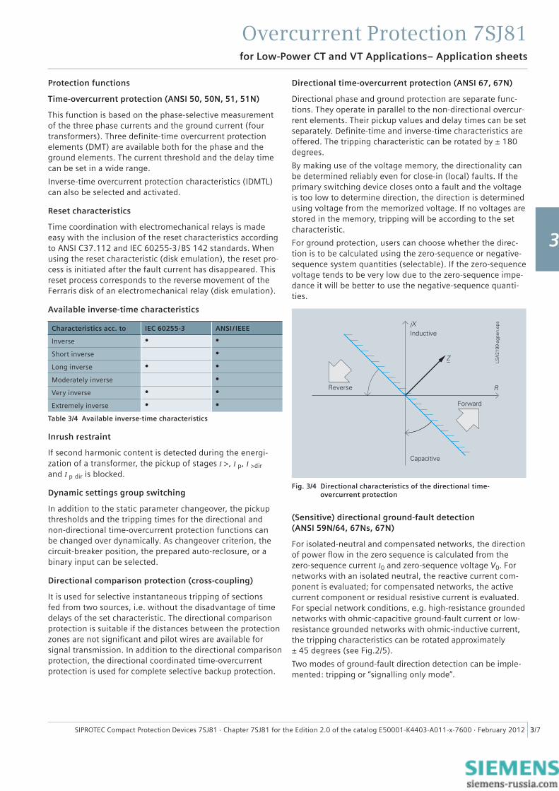
Directional time-overcurrent protection (ANSI 67, 67N)
Directional phase and ground protection are separate func-tions. They operate in parallel to the non-directional overcur-rent elements. Their pickup values and delay times can be set separately. Defi nite-time and inverse-time characteristics areoffered. The tripping characteristic can be rotated by ± 180 degrees.
By making use of the voltage memory, the directionality can be determined reliably even for close-in (local) faults. If the primary switching device closes onto a fault and the voltage is too low to determine direction, the direction is determined using voltage from the memorized voltage. If no voltages are stored in the memory, tripping will be according to the set characteristic.
For ground protection, users can choose whether the direc-tion is to be calculated using the zero-sequence or negative-sequence system quantities (selectable). If the zero-sequence voltage tends to be very low due to the zero-sequence impe-dance it will be better to use the negative-sequence quanti-ties.
(Sensitive) directional ground-fault detection (ANSI 59N/64, 67Ns, 67N)
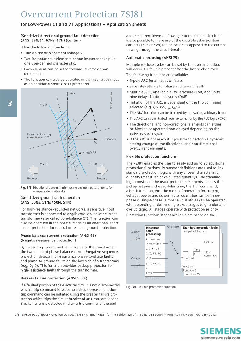
For isolated-neutral and compensated networks, the direction of power fl ow in the zero sequence is calculated from the zero-sequence current I0 and zero-sequence voltage V0. For networks with an isolated neutral, the reactive current com-ponent is evaluated; for compensated networks, the active current component or residual resistive current is evaluated. For special network conditions, e.g. high-resistance grounded networks with ohmic-capacitive ground-fault current or low-resistance grounded networks with ohmic-inductive current, the tripping characteristics can be rotated approximately ± 45 degrees (see Fig.2/5).
Two modes of ground-fault direction detection can be imple-mented: tripping or “signalling only mode”.
Fig. 3/4 Directional characteristics of the directional time- overcurrent protection
1
2
3
4
5
6
7
8
9
Overcurrent Protection 7SJ81
3/8 SIPROTEC Compact Protection Devices 7SJ81 · Chapter 7SJ81 for the Edition 2.0 of the catalog E50001-K4403-A011-x-7600 · February 2012
(Sensitive) directional ground-fault detection (ANSI 59N/64, 67Ns, 67N) (contin.)
It has the following functions:
• TRIP via the displacement voltage VE
• Two instantaneous elements or one instantaneous plus one user-defi ned characteristic.
• Each element can be set to forward, reverse or non-directional.
• The function can also be operated in the insensitive mode as an additional short-circuit protection.
(Sensitive) ground-fault detection (ANSI 50Ns, 51Ns / 50N, 51N)
For high-resistance grounded networks, a sensitive input transformer is connected to a split-core low-power current transformer (also called core-balance CT). The function can also be operated in the normal mode as an additional short-circuit protection for neutral or residual ground protection.
Phase-balance current protection (ANSI 46)(Negative-sequence protection)
By measuring current on the high side of the transformer, the two-element phase-balance current/negative-sequence protection detects high-resistance phase-to-phase faults and phase-to-ground faults on the low side of a transformer (e.g. Dy 5). This function provides backup protection for high-resistance faults through the transformer.
Breaker failure protection (ANSI 50BF)
If a faulted portion of the electrical circuit is not disconnected when a trip command is issued to a circuit-breaker, another trip command can be initiated using the breaker failure pro-tection which trips the circuit-breaker of an upstream feeder. Breaker failure is detected if, after a trip command is issued
for Low-Power CT and VT Applications – Application sheets
and the current keeps on fl owing into the faulted circuit. It is also possible to make use of the circuit-breaker position contacts (52a or 52b) for indication as opposed to the current fl owing through the circuit-breaker.
Automatic reclosing (ANSI 79)
Multiple re-close cycles can be set by the user and lockout will occur if a fault is present after the last re-close cycle.
The following functions are available:
• 3-pole ARC for all types of faults
• Separate settings for phase and ground faults
• Multiple ARC, one rapid auto-reclosure (RAR) and up to nine delayed auto-reclosures (DAR)
• Initiation of the ARC is dependant on the trip command selected (e.g. I2>, I>>, Ip, Idir>)
• The ARC function can be blocked by activating a binary input
• The ARC can be initiated from external or by the PLC logic (CFC)
• The directional and non-directional elements can either be blocked or operated non-delayed depending on the auto-reclosure cycle
• If the ARC is not ready it is possible to perform a dynamic setting change of the directional and non-directional overcurrent elements.
Flexible protection functions
The 7SJ81 enables the user to easily add up to 20 additional protection functions. Parameter defi nitions are used to link standard protection logic with any chosen characteristic quantity (measured or calculated quantity). The standard logic consists of the usual protection elements such as the pickup set point, the set delay time, the TRIP command, a block function, etc. The mode of operation for current, voltage, power and power factor quantities can be three-phase or single-phase. Almost all quantities can be operated with ascending or descending pickup stages (e.g. under and overvoltage). All stages operate with protection priority.
Protection functions/stages available are based on the
Fig. 3/5 Directional determination using cosine measurements for compensated networks
Fig, 3/6 Flexible protection function
3
Overcurrent Protection 7SJ81
3/9SIPROTEC Compact Protection Devices 7SJ81 · Chapter 7SJ81 for the Edition 2.0 of the catalog E50001-K4403-A011-x-7600 · February 2012
for Low-Power CT and VT Applications – Application sheets
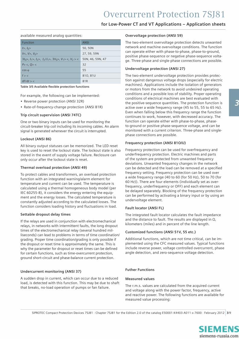
available measured analog quantities:
Function ANSI
I>, IE> 50, 50N
V<, V>, VE> 27, 59, 59N
3I0>, I1>, I2>, I2/ I1>, 3V0>, V1> <, V2 > < 50N, 46, 59N, 47
P> <, Q> < 32
cos ϕ 55
f > < 81O, 81U
df / dt > < 81R
Table 3/5 Available fl exible protection functions
For example, the following can be implemented:
• Reverse power protection (ANSI 32R)
• Rate-of-frequency-change protection (ANSI 81R)
Trip circuit supervision (ANSI 74TC)
One or two binary inputs can be used for monitoring the circuit-breaker trip coil including its incoming cables. An alarm signal is generated whenever the circuit is interrupted.
Lockout (ANSI 86)
All binary output statuses can be memorized. The LED reset key is used to reset the lockout state. The lockout state is also stored in the event of supply voltage failure. Reclosure can only occur after the lockout state is reset.
Thermal overload protection (ANSI 49)
To protect cables and transformers, an overload protection function with an integrated warning/alarm element for temperature and current can be used. The temperature is calculated using a thermal homogeneous body model (per IEC 60255-8), it considers the energy entering the equip-ment and the energy losses. The calculated temperature is constantly adjusted according to the calculated losses. The function considers loading history and fl uctuations in load.
Settable dropout delay times
If the relays are used in conjunction with electromechanical relays, in networks with intermittent faults, the long dropout times of the electromechanical relay (several hundred mil-liseconds) can lead to problems in terms of time coordination/grading. Proper time coordination/grading is only possible if the dropout or reset time is approximately the same. This is why the parameter for dropout or reset times can be defi ned for certain functions, such as time-overcurrent protection, ground short-circuit and phase-balance current protection.
Undercurrent monitoring (ANSI 37)
A sudden drop in current, which can occur due to a reduced load, is detected with this function. This may be due to shaft that breaks, no-load operation of pumps or fan failure.
Overvoltage protection (ANSI 59)
The two-element overvoltage protection detects unwanted network and machine overvoltage conditions. The function can operate either with phase-to-phase, phase-to-ground, positive phase-sequence or negative phase-sequence volta-ge. Three-phase and single-phase connections are possible.
Undervoltage protection (ANSI 27)
The two-element undervoltage protection provides protec-tion against dangerous voltage drops (especially for electric machines). Applications include the isolation of generators or motors from the network to avoid undesired operating conditions and a possible loss of stability. Proper operating conditions of electrical machines are best evaluated with the positive-sequence quantities. The protection function is active over a wide frequency range (45 to 55, 55 to 65 Hz). Even when falling below this frequency range the function continues to work, however, with decreased accuracy. The function can operate either with phase-to-phase, phase-to-ground or positive phase-sequence voltage, and can be monitored with a current criterion. Three-phase and single-phase connections are possible.
Frequency protection (ANSI 81O/U)
Frequency protection can be used for overfrequency and underfrequency protection. Electric machines and parts of the system are protected from unwanted frequency deviations. Unwanted frequency changes in the network can be detected and the load can be removed at a specifi ed frequency setting. Frequency protection can be used over a wide frequency range (40 to 60 (for 50 Hz), 50 to 70 (for 60 Hz)). There are four elements (individually set as over-frequency, underfrequency or OFF) and each element can be delayed separately. Blocking of the frequency protection can be performed by activating a binary input or by using an undervoltage element.
Fault locator (ANSI FL)
The integrated fault locator calculates the fault impedance and the distance to fault. The results are displayed in Ω, kilometers (miles) and in percent of the line length.
Customized functions (ANSI 51V, 55 etc.)
Additional functions, which are not time critical, can be im-plemented using the CFC measured values. Typical functions include reverse power, voltage controlled overcurrent, phase angle detection, and zero-sequence voltage detection.
Futher Functions
Measured values
The r.m.s. values are calculated from the acquired current and voltage along with the power factor, frequency, active and reactive power. The following functions are available for measured value processing:
1
2
3
4
5
6
7
8
9
Overcurrent Protection 7SJ81
3/10 SIPROTEC Compact Protection Devices 7SJ81 · Chapter 7SJ81 for the Edition 2.0 of the catalog E50001-K4403-A011-x-7600 · February 2012
for Low-Power CT and VT Applications – Application sheets
Measured values (contin.)
• Currents IL1, IL2, IL3, IN, IEE
• Voltages VL1, VL2, VL3, V12, V23, V31
• Symmetrical components I1, I2, 3I0; V1, V2, 3V0
• Power Watts, Vars, VA/P, Q, S (P, Q: total and phase selective)
• Power factor cos ϕ (total and phase selective)
• Frequency
• Energy ± kWh, ± kVarh, forward and reverse power fl ow
• Mean as well as minimum and maximum current and voltage values
• Operating hours counter
• Mean operating temperature of the overload function
• Limit value monitoringLimit values can be monitored using programmable logic in the CFC. Commands can be derived from this limit value indication.
• Zero suppression In a certain range of very low measured values, the value is set to zero to suppress interference.
Metered values
For internal metering, the unit can calculate an energy me-tered value from the measured current and voltage values. If an external meter with a metering pulse output is available, the 7SJ81 can obtain and process metering pulses through an indication input. The metered values can be displayed and passed on to a control center as an accumulated value with reset. A distinction is made between forward, reverse, active and reactive energy.
Circuit-breaker wear monitoring/circuit-breaker remaining service life
Methods for determining circuit-breaker contact wear or the remaining service life of a circuit-breaker (CB) allow CB maintenance intervals to be aligned to their actual degree of wear. The benefi t lies in reduced maintenance costs.
There is no exact mathematical method to calculate the wear or the remaining service life of a circuit-breaker that takes arc-chamber’s physical conditions into account when the CB opens.
This is why various methods of determining CB wear have evolved which refl ect the different operator philosophies. To do justice to these, the relay offers several methods:
• ΣI• ΣIx, with x = 1..3
• Σi2t.
The devices also offer a new method for determining the remaining service life:
• Two-point method.
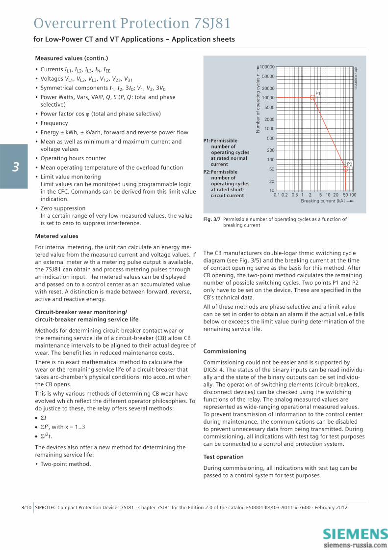
The CB manufacturers double-logarithmic switching cycle diagram (see Fig. 3/5) and the breaking current at the time of contact opening serve as the basis for this method. After CB opening, the two-point method calculates the remaining number of possible switching cycles. Two points P1 and P2 only have to be set on the device. These are specifi ed in the CB’s technical data.
All of these methods are phase-selective and a limit value can be set in order to obtain an alarm if the actual value falls below or exceeds the limit value during determination of the remaining service life.
Commissioning
Commissioning could not be easier and is supported by DIGSI 4. The status of the binary inputs can be read individu-ally and the state of the binary outputs can be set individu-ally. The operation of switching elements (circuit-breakers, disconnect devices) can be checked using the switching functions of the relay. The analog measured values are represented as wide-ranging operational measured values. To prevent transmission of information to the control center during maintenance, the communications can be disabled to prevent unnecessary data from being transmitted. During commissioning, all indications with test tag for test purposes can be connected to a control and protection system.
Test operation
During commissioning, all indications with test tag can be passed to a control system for test purposes.
Fig. 3/7 Permissible number of operating cycles as a function of breaking current
P1: Permissible number of operating cycles at rated normal current
P2: Permissible number of operating cycles at rated short- circuit current
3
Overcurrent Protection 7SJ81
3/11SIPROTEC Compact Protection Devices 7SJ81 · Chapter 7SJ81 for the Edition 2.0 of the catalog E50001-K4403-A011-x-7600 · February 2012
for Low-Power CT and VT Applications – Application examples
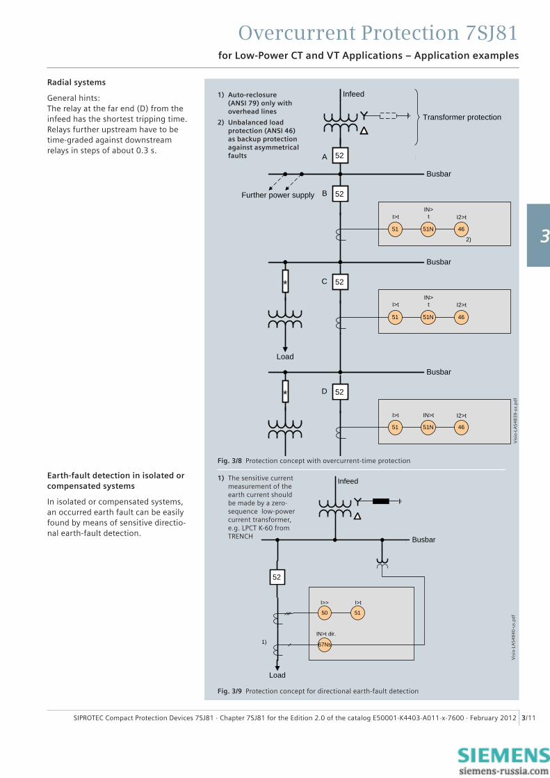
Fig. 3/8 Protection concept with overcurrent-time protection
Radial systems
General hints:The relay at the far end (D) from the infeed has the shortest tripping time. Relays further upstream have to be time-graded against downstream relays in steps of about 0.3 s.
Earth-fault detection in isolated or compensated systems
In isolated or compensated systems, an occurred earth fault can be easily found by means of sensitive directio-nal earth-fault detection.
Infeed
Transformer protection
Busbar
51 51N 46
2)
Busbar
Load
51 51N 46
Busbar
51 51N 46
D
C
B
A
Further power supply
I2>t
I>tIN>
t
IN>t
I2>t
I>t
I>t IN>t I2>t
*
*
52
52
52
52
Fig. 3/9 Protection concept for directional earth-fault detection
Vis
io-L
AS4
83
9-u
s.p
df
1) Auto-reclosure (ANSI 79) only with overhead lines
2) Unbalanced load protection (ANSI 46) as backup protection against asymmetrical faults
1) The sensitive current measurement of the earth current should be made by a zero-sequence low-power current transformer, e.g. LPCT K-60 from TRENCH Busbar
IN>t dir.
Load
Infeed
50 51
67Ns
I>> I>t
52
1)
Vis
io-L
AS4
84
0-u
s.p
df
1
2
3
4
5
6
7
8
9
Overcurrent Protection 7SJ81
3/12 SIPROTEC Compact Protection Devices 7SJ81 · Chapter 7SJ81 for the Edition 2.0 of the catalog E50001-K4403-A011-x-7600 · February 2012
for Low-Power CT and VT Applications – application examples
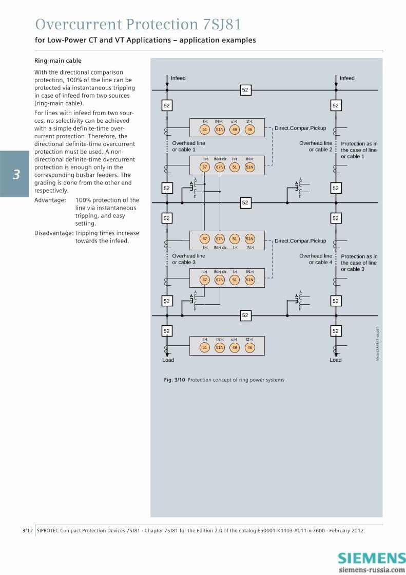
Ring-main cable
With the directional comparison protection, 100% of the line can be protected via instantaneous tripping in case of infeed from two sources (ring-main cable).
For lines with infeed from two sour-ces, no selectivity can be achieved with a simple defi nite-time over-current protection. Therefore, the directional defi nite-time overcurrent protection must be used. A non-directional defi nite-time overcurrent protection is enough only in the corresponding busbar feeders. The grading is done from the other end respectively.
Advantage: 100% protection of the line via instantaneous tripping, and easy setting.
Disadvantage: Tripping times increase towards the infeed.
Fig. 3/10 Protection concept of ring power systems
67 67N 51 51N
51 51N 49 46
Overhead line or cable 1
Direct.Compar.Pickup
Overhead line or cable 2
Protection as in the case of line or cable 1
Infeed Infeed
67 67N 51 51N
67 67N 51 51N
Overhead line or cable 3
Direct.Compar.Pickup
Overhead line or cable 4
Protection as in the case of line or cable 3
51 51N 49 46
Load Load
I>t IN>t >t I2>t
I>t IN>t dir. I>t IN>t
I>t IN>t >t I2>t
I>t IN>t dir. I>t IN>t
I>t IN>t dir. I>t IN>t
52
52
52
52
52
52
52
52
52
52
52
52 52
Vis
io-L
SA4
84
1-u
s.p
df
3
Overcurrent Protection 7SJ81
3/13SIPROTEC Compact Protection Devices 7SJ81 · Chapter 7SJ81 for the Edition 2.0 of the catalog E50001-K4403-A011-x-7600 · February 2012
for Low-Power CT and VT Applications – application examples
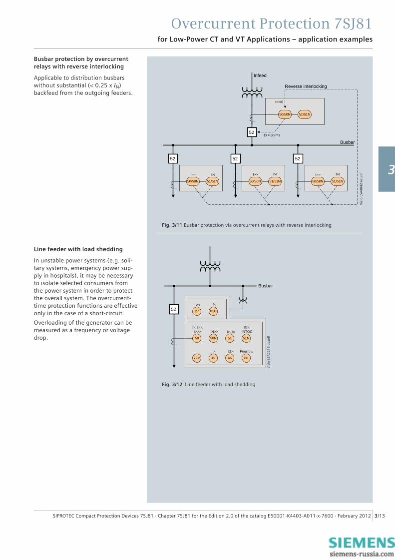
Fig. 3/11 Busbar protection via overcurrent relays with reverse interlocking
Fig. 3/12 Line feeder with load shedding
Busbar protection by overcurrent relays with reverse interlocking
Applicable to distribution busbars without substantial (< 0.25 x IN) backfeed from the outgoing feeders.
Line feeder with load shedding
In unstable power systems (e.g. soli-tary systems, emergency power sup-ply in hospitals), it may be necessary to isolate selected consumers from the power system in order to protect the overall system. The overcurrent-time protection functions are effective only in the case of a short-circuit.
Overloading of the generator can be measured as a frequency or voltage drop.
Busbar
Infeed
50/50N 51/51N 50/50N 51/51N 50/50N 51/51N
50/50N 51/51N
t0 = 50 ms
Reverse interlocking
I>>t0
I>> I>t I>> I>> I>tI>t
52 52 52
52
Busbar
I>, I>>, I>>> IN>>
50 50N
79M
51 51N
49 46 86
Final trip
27 81U
V< f<
> I2>
I>, IpIN>,
INTOC
52
Vis
io-L
SA4
84
2-u
s.p
df
Vis
io-L
SA2
21
6-u
s.p
df
1
2
3
4
5
6
7
8
9
Overcurrent Protection 7SJ81
3/14 SIPROTEC Compact Protection Devices 7SJ81 · Chapter 7SJ81 for the Edition 2.0 of the catalog E50001-K4403-A011-x-7600 · February 2012
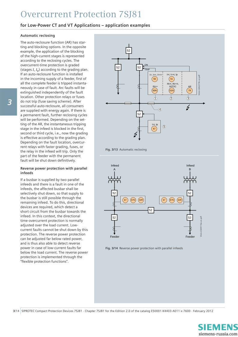
Fig. 3/13 Automatic reclosing
Automatic reclosing
The auto-reclosure function (AR) has star-ting and blocking options. In the opposite example, the application of the blocking of the high-current stages is represented according to the reclosing cycles. The overcurrent-time protection is graded (stages I, Ip) according to the grading plan. If an auto-reclosure function is installed in the incoming supply of a feeder, fi rst of all the complete feeder is tripped instanta-neously in case of fault. Arc faults will be extinguished independently of the fault location. Other protection relays or fuses do not trip (fuse saving scheme). After successful auto-reclosure, all consumers are supplied with energy again. If there is a permanent fault, further reclosing cycles will be performed. Depending on the set-ting of the AR, the instantaneous tripping stage in the infeed is blocked in the fi rst, second or third cycle, i.e., now the grading is effective according to the grading plan. Depending on the fault location, overcur-rent relays with faster grading, fuses, or the relay in the infeed will trip. Only the part of the feeder with the permanent fault will be shut down defi nitively.
Reverse power protection with parallel infeeds
If a busbar is supplied by two parallel infeeds and there is a fault in one of the infeeds, the affected busbar shall be selectively shut down, so that supply to the busbar is still possible through the remaining infeed. To do this, directional devices are required, which detect a short circuit from the busbar towards the infeed. In this context, the directional time-overcurrent protection is normally adjusted over the load current. Low-current faults cannot be shut down by this protection. The reverse power protection can be adjusted far below rated power, and is thus also able to detect reverse power in case of low-current faults far below the load current. The reverse power protection is implemented through the “fl exible protection functions”.
Fig. 3/14 Reverse power protection with parallel infeeds
67
50N
IN>> AR
51N 79
IN>t, IN>>t, INTOC
50
I>, I>>, I>>>
51
2 3
4
1
ON
TRIP
I>t, I>>t, Ip
I>t, Ip5
52 52
52
52
Feeder Feeder
Infeed InfeedA
67 67N 32R
B
67 67N 32R
52
52
52
52
52
Vis
io-L
SA2
21
9c-
us.
pd
fV
isio
-LSA
41
16
a-u
s.p
df
for Low-Power CT and VT Applications – application examples
3
Overcurrent Protection 7SJ81
3/15SIPROTEC Compact Protection Devices 7SJ81 · Chapter 7SJ81 for the Edition 2.0 of the catalog E50001-K4403-A011-x-7600 · February 2012
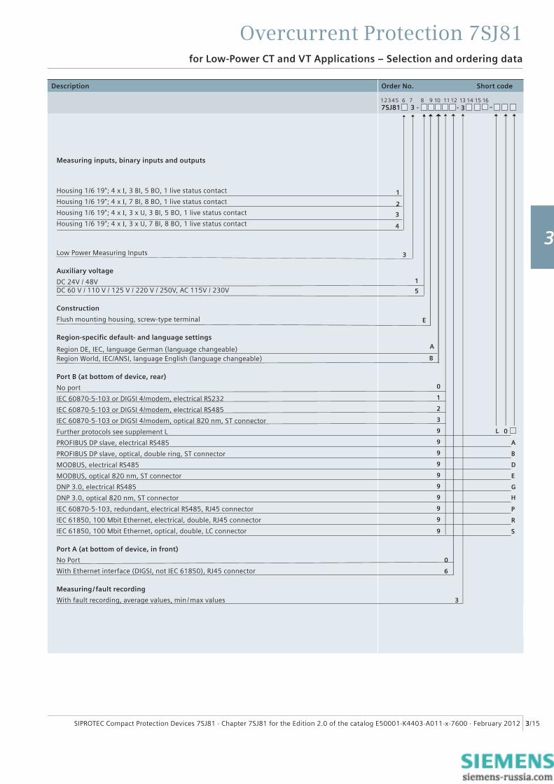
for Low-Power CT and VT Applications – Selection and ordering data
Description Order No. Short code
7SJ81 3 - - 3 –
Measuring inputs, binary inputs and outputs
Housing 1/6 19"; 4 x I, 3 BI, 5 BO, 1 live status contact
Housing 1/6 19"; 4 x I, 7 BI, 8 BO, 1 live status contact
Housing 1/6 19"; 4 x I, 3 x U, 3 BI, 5 BO, 1 live status contact
Housing 1/6 19"; 4 x I, 3 x U, 7 BI, 8 BO, 1 live status contact
Low Power Measuring Inputs
Auxiliary voltage
DC 24V / 48VDC 60 V / 110 V / 125 V / 220 V / 250V, AC 115V / 230V
Construction
Flush mounting housing, screw-type terminal
Region-specifi c default- and language settings
Region DE, IEC, language German (language changeable)Region World, IEC/ANSI, language English (language changeable)
Port B (at bottom of device, rear)
No port
IEC 60870-5-103 or DIGSI 4/modem, electrical RS232
IEC 60870-5-103 or DIGSI 4/modem, electrical RS485
IEC 60870-5-103 or DIGSI 4/modem, optical 820 nm, ST connector
Further protocols see supplement L
PROFIBUS DP slave, electrical RS485
PROFIBUS DP slave, optical, double ring, ST connector
MODBUS, electrical RS485
MODBUS, optical 820 nm, ST connector
DNP 3.0, electrical RS485
DNP 3.0, optical 820 nm, ST connector
IEC 60870-5-103, redundant, electrical RS485, RJ45 connector
IEC 61850, 100 Mbit Ethernet, electrical, double, RJ45 connector
IEC 61850, 100 Mbit Ethernet, optical, double, LC connector
Port A (at bottom of device, in front)
No Port
With Ethernet interface (DIGSI, not IEC 61850), RJ45 connector
Measuring / fault recording
With fault recording, average values, min /max values
1
2
5
E
0
6
3
B
0
A
0L
1
B
2
D
3
E
9
9
9
9
9
9
9
9
9
9
G
H
P
R
S
12345 6 7 8 9 10 11 12 13 14 15 16
3
4
1
3
A
1
2
3
4
5
6
7
8
9
Overcurrent Protection 7SJ81
3/16 SIPROTEC Compact Protection Devices 7SJ81 · Chapter 7SJ81 for the Edition 2.0 of the catalog E50001-K4403-A011-x-7600 · February 2012
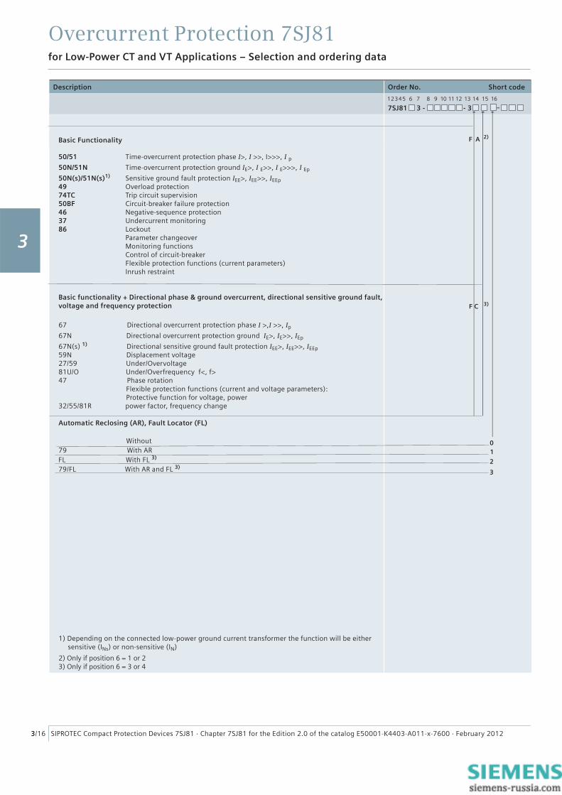
50/51 Time-overcurrent protection phase I>, I >>, I>>>, I p50N/51N Time-overcurrent protection ground IE>, I E>>, I E>>>, I Ep
50N(s)/51N(s)1) Sensitive ground fault protection IEE>, IEE>>, IEEp49 Overload protection74TC Trip circuit supervision50BF Circuit-breaker failure protection46 Negative-sequence protection37 Undercurrent monitoring86 Lockout Parameter changeover Monitoring functions Control of circuit-breaker Flexible protection functions (current parameters) Inrush restraint
Basic functionality + Directional phase & ground overcurrent, directional sensitive ground fault,voltage and frequency protection
67 Directional overcurrent protection phase I >,I >>, Ip
67N Directional overcurrent protection ground IE>, IE>>, IEp
67N(s) 1) Directional sensitive ground fault protection IEE>, IEE>>, IEEp59N Displacement voltage27/59 Under/Overvoltage81U/O Under/Overfrequency f<, f>47 Phase rotation Flexible protection functions (current and voltage parameters): Protective function for voltage, power 32/55/81R power factor, frequency change
Automatic Reclosing (AR), Fault Locator (FL) Without79 With ARFL With FL 3)
79/FL With AR and FL 3)
1) Depending on the connected low-power ground current transformer the function will be either sensitive (INs) or non-sensitive (IN)
2) Only if position 6 = 1 or 23) Only if position 6 = 3 or 4
Description Order No. Short code
7SJ81 3 - - 3 –
Basic Functionality
12345 6 7 8 9 10 11 12 13 14 15 16
C 3)F
A 2)F
01
2
3
for Low-Power CT and VT Applications – Selection and ordering data
3
Overcurrent Protection 7SJ81
3/17SIPROTEC Compact Protection Devices 7SJ81 · Chapter 7SJ81 for the Edition 2.0 of the catalog E50001-K4403-A011-x-7600 · February 2012
for Low-Power CT and VT Applications – Connection diagrams
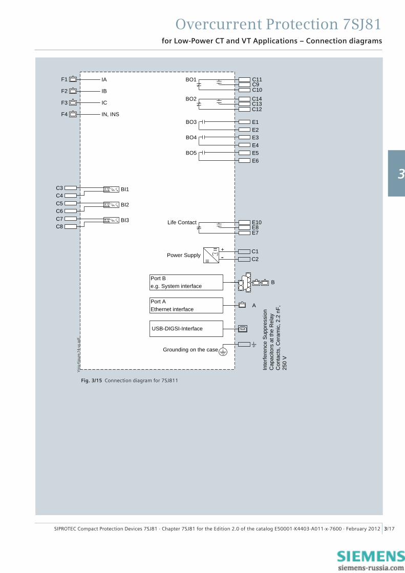
Fig. 3/15 Connection diagram for 7SJ811
C7C8
BI3
C5C6
BI2
C3C4
BI1
C1C2=
=(~)
+-Power Supply
B
Grounding on the case
Life Contact E10E8E7
Inte
rfere
nce
Sup
pres
sion
C
apac
itors
at t
he R
elay
C
onta
cts,
Cer
amic
, 2.2
nF,
25
0 V
BO1
BO2 C14C13C12
A
USB-DIGSI-Interface
Port Be.g. System interface
Port AEthernet interface
C11
C10C9
F4
F3
F2
F1
IC
IA
IN, INS
IB
E1E2
BO3
E3E4
BO4
E5E6
BO5
Vis
io-F
igu
re-1
4-u
s.p
df
1
2
3
4
5
6
7
8
9
Overcurrent Protection 7SJ81
3/18 SIPROTEC Compact Protection Devices 7SJ81 · Chapter 7SJ81 for the Edition 2.0 of the catalog E50001-K4403-A011-x-7600 · February 2012
for Low-Power CT and VT Applications – Connection diagrams
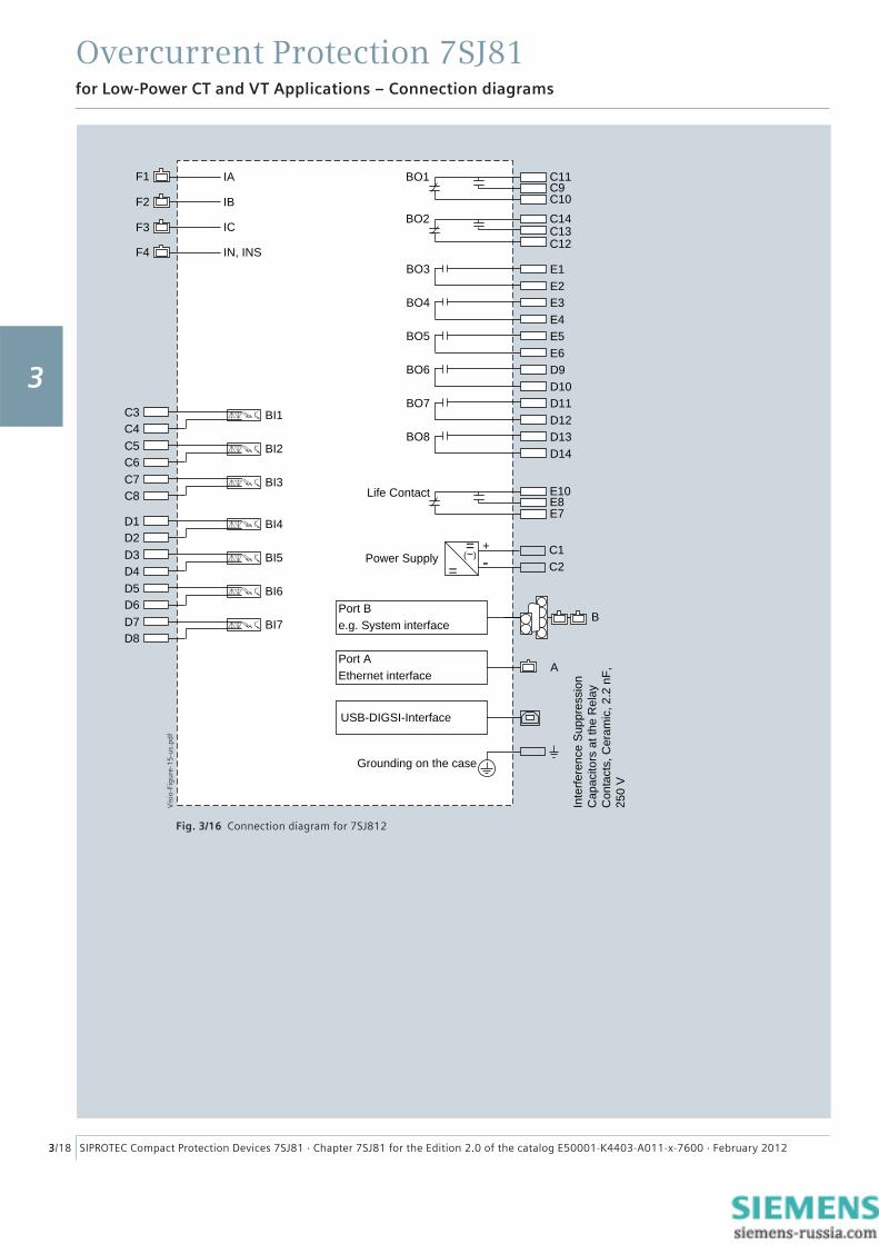
Fig. 3/16 Connection diagram for 7SJ812
D7D8
BI7
D5D6
BI6
D3D4
BI5
D1D2
BI4
C7C8
BI3
C5C6
BI2
C3C4
BI1
C1C2=
=(~)
+-Power Supply
B
Grounding on the case
Life Contact E10E8E7
Inte
rfere
nce
Sup
pres
sion
C
apac
itors
at t
he R
elay
C
onta
cts,
Cer
amic
, 2.2
nF,
25
0 V
BO1 C11C9C10
BO2 C14C13C12
A
USB-DIGSI-Interface
Port Be.g. System interface
Port AEthernet interface
F4
F3
F2
F1 IA
IC
IN, INS
IB
E1E2
BO3
E3E4
BO4
E5E6
BO5
D9D10
BO6
D11D12
BO7
D13D14
BO8
Vis
io-F
igu
re-1
5-u
s.p
df
3

Overcurrent Protection 7SJ81
3/19SIPROTEC Compact Protection Devices 7SJ81 · Chapter 7SJ81 for the Edition 2.0 of the catalog E50001-K4403-A011-x-7600 · February 2012
for Low-Power CT and VT Applications – Connection diagrams
Fig. 3/17 Connection diagram for 7SJ813
C7C8
BI3
C5C6
BI2
C3C4
BI1
C1C2=
=(~)
+-Power Supply
B
Grounding on the case
Inte
rfere
nce
Sup
pres
sion
C
apac
itors
at t
he R
elay
C
onta
cts,
Cer
amic
, 2.2
nF,
25
0 V
A
USB-DIGSI-Interface
Port Be.g. System interface
Port AEthernet interface
BO1 C11C9C10
BO2 C14C13C12
Life Contact E10E8E7
F4
F3
F2
F1 IA
IC
IN, INS
IBVA-N
VB-N
VC-NE1E2
BO3
E3E4
BO4
E5E6
BO5
Vis
io-F
igu
re-1
6-u
s.p
df
1
2
3
4
5
6
7
8
9
Overcurrent Protection 7SJ81
3/20 SIPROTEC Compact Protection Devices 7SJ81 · Chapter 7SJ81 for the Edition 2.0 of the catalog E50001-K4403-A011-x-7600 · February 2012
for Low-Power CT and VT Applications – Connection diagrams
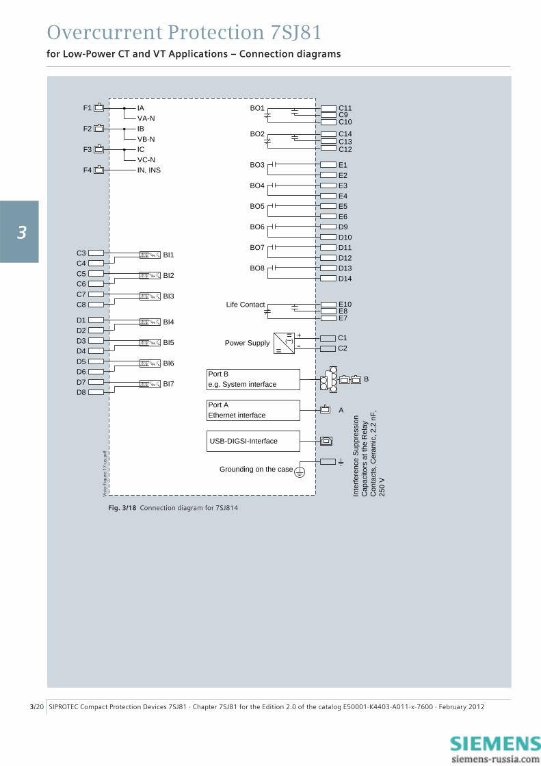
Fig. 3/18 Connection diagram for 7SJ814
D7D8
BI7
D5D6
BI6
D3D4
BI5
D1D2
BI4
C7C8
BI3
C5C6
BI2
C3C4
BI1
C1C2=
=(~)
+-Power Supply
B
Grounding on the case
Inte
rfere
nce
Sup
pres
sion
C
apac
itors
at t
he R
elay
C
onta
cts,
Cer
amic
, 2.2
nF,
25
0 V
A
USB-DIGSI-Interface
Port Be.g. System interface
Port AEthernet interface
BO1 C11C9C10
BO2 C14C13C12
Life Contact E10E8E7
F4
F3
F2
F1 IA
IC
IN, INS
IBVA-N
VB-N
VC-NE1E2
BO3
E3E4
BO4
E5E6
BO5
D9D10
BO6
D11D12
BO7
D13D14
BO8
Vis
io-F
igu
re-1
7-u
s.p
df
3
Overcurrent Protection 7SJ81
3/21SIPROTEC Compact Protection Devices 7SJ81 · Chapter 7SJ81 for the Edition 2.0 of the catalog E50001-K4403-A011-x-7600 · February 2012
for Low-P ower CT and VT Applications – Connection example
SIPROTECA B C
Flush Mounting Housing
F1
F2
F3
F4
IA
IB
IC
IN
5252 52
* * *
SIPROTECA B C
Flush Mounting Housing
F1
F2
F3
F4
IA
IB
IC
IN
5252 52
* * *
*
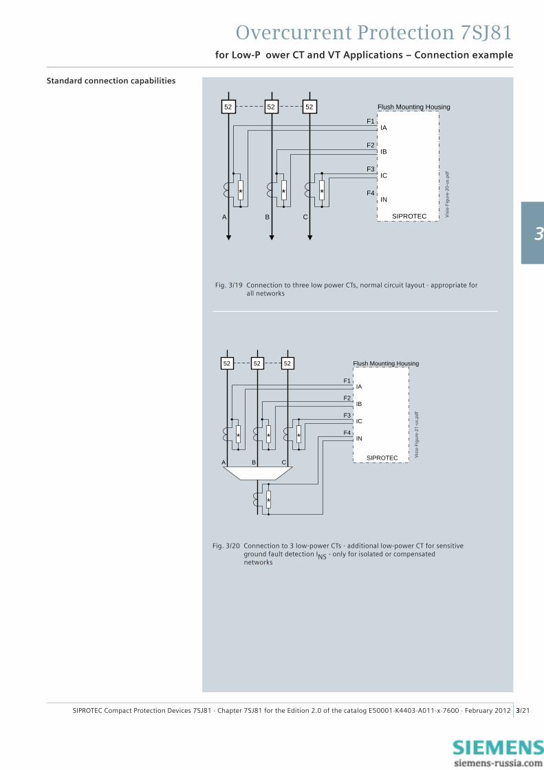
Standard connection capabilities
Fig. 3/20 Connection to 3 low-power CTs - additional low-power CT for sensitive ground fault detection INS - only for isolated or compensated networks
Fig. 3/19 Connection to three low power CTs, normal circuit layout - appropriate for all networks
Vis
io-F
igu
re-2
0-u
s.p
df
Vis
io-F
igu
re-2
1-u
s.p
df
1
2
3
4
5
6
7
8
9
Overcurrent Protection 7SJ81
3/22 SIPROTEC Compact Protection Devices 7SJ81 · Chapter 7SJ81 for the Edition 2.0 of the catalog E50001-K4403-A011-x-7600 · February 2012
for Low-P ower CT and VT Applications – Connection example
SIPROTEC
A B C
Flush Mounting Housing
F2
F3
F4
LPCT
IA
IB
IC
IN
VA-N
VB-N
VC-N
F1R1 R2
R1 R2
R1 R2
LPCT/LPVT
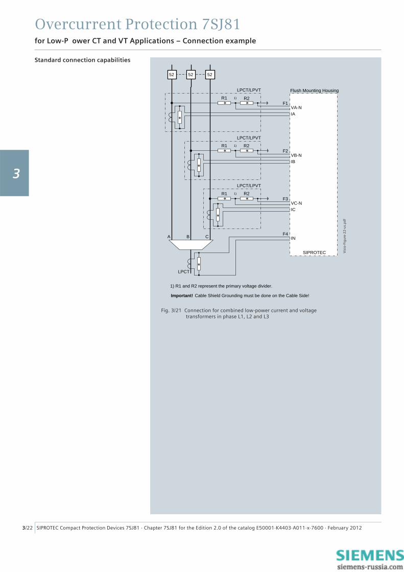
Important! Cable Shield Grounding must be done on the Cable Side!
1)
1)
1)
LPCT/LPVT
LPCT/LPVT
5252 52
* *
* *
* *
*
*
*
*
1) R1 and R2 represent the primary voltage divider.
Standard connection capabilities
Fig. 3/21 Connection for combined low-power current and voltage transformers in phase L1, L2 and L3
Vis
io-F
igu
re-2
2-u
s.p
df
3
Overcurrent Protection 7SJ81
3/23SIPROTEC Compact Protection Devices 7SJ81 · Chapter 7SJ81 for the Edition 2.0 of the catalog E50001-K4403-A011-x-7600 · February 2012
SIPROTEC
A B C
Flush Mounting Housing
F2
F3
F4LPCT
LPCT
IA
IB
IC
IN
VA-N
VB-N
VC-N
F1
R1 R2
R1 R2
R1 R2
1)
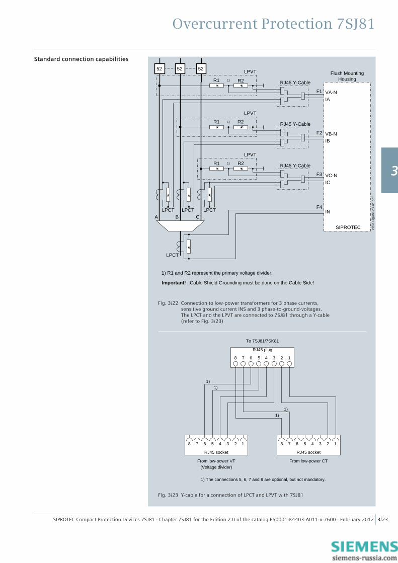
Important! Cable Shield Grounding must be done on the Cable Side!
1)
1)
LPVT
LPVT
LPVT
LPCT LPCT
5252 52
* *
* *
* *
***
*
RJ45 Y-Cable
RJ45 Y-Cable
RJ45 Y-Cable
1) R1 and R2 represent the primary voltage divider.
Fig. 3/22 Connection to low-power transformers for 3 phase currents, sensitive ground current INS and 3 phase-to-ground-voltages. The LPCT and the LPVT are connected to 7SJ81 through a Y-cable (refer to Fig. 3/23)
Standard connection capabilities
RJ45 socketRJ45 socket
RJ45 plug
8 7 6 5 4 3 2 1
8 7 6 5 4 3 2 1 8 7 6 5 4 3 2 1
To 7SJ81/7SK81
From low-power VT From low-power CT(Voltage divider)
1)1)
1)1)
1) The connections 5, 6, 7 and 8 are optional, but not mandatory.
Fig. 3/23 Y-cable for a connection of LPCT and LPVT with 7SJ81
Vis
io-F
igu
re-2
3-u
s.p
df
1
2
3
4
5
6
7
8
9