sispro building 2 - schneider electric · sispro building is a comprehensive work tool used to...
TRANSCRIPT

SISpro building 2.1
User's reference manual

SISpro building 2.1 Page 2

Contents
Overview .................................................................................................................................. .5 .Project step ............................................................................................................................ .13.Design step ............................................................................................................................ .17.Single line diagram step ....................................................................................................... .191.Quotation step ...................................................................................................................... .195.Order form step .................................................................................................................... .219.Using data ............................................................................................................................ .231.Customising the software ..................................................................................................... .239.Additional functions .............................................................................................................. .257.Appendices ............................................................................................................................271.Glossary ............................................................................................................................... .281.Index ......................................................................................................................................283.
SISpro building 2.1 Page 3

Page 4

Overview
SISpro building 2.1 ................................................................................................................... .6 .The various project steps ......................................................................................................... .7 .The SISpro building window ..................................................................................................... .9 .Important notions .....................................................................................................................11.
SISpro building 2.1 Page 5

SISpro building 2.1
SISpro building is a comprehensive work tool used to design and calculate electrical equipmentfor buildings. It is used to:
• structure a project into functional zones representative of the organisation of the building tobe equipped,
• design electrical equipment (switchboards and enclosures) for the installation: choice ofequipment, organisation of electrical cabling, mounting in the switchboard,
• draw up a quotation for the installation with the option of comparing several technical orsales solutions,
• create order forms,
• print or export data obtained to your standard office automation software:- equipment lists,- equipment single-line diagrams,- switchboard front panel drawings,- mounting documents,- quotation,- order forms,
You have various options for adapting software behaviour to your working preferences andhabits. For example you can customise window display, customise menus and tool bars anddefine the folders in which data are saved.
Overview - SISpro building 2.1
Page 6

The various project steps
A project is completed in 5 main steps.
Project
This step consists of defining various pieces of administrative information for the project. Thisinformation may then be used in the project documents such as front panel drawings,quotations or order forms. For more details, see Enter project information (p.14).
Design
In this step:
• You structure the project into functional zones representative of the organisation of thebuilding to be equipped.
• You design electrical equipment and define technical data: choice of equipment, deviceelectrical cabling, mounting of devices in wall mounted or floor standing enclosures.
• You can also generate the front panel drawings of switchboards and create identificationlabels for wall mounted enclosures.
For more details, see Design step (p.18).
Single line diagram
In this step, you may launch the automatic generation of single-line diagrams for the variousequipments of the project. You can choose the equipment to take into account. For moredetails, see Generate single-line diagrams (p.192).
Quotation
In this step, you draw up the project quotation. You can create a number of quotations forcomparison purposes. These quotations may correspond to different technical solutions(different equipment content) or to different calculation solutions (services, margins, discounts,forced prices). For more details, see Quotation step (p.196).
Order form
In this step, you create the order forms intended for your suppliers. For more details, see Orderform step (p.220).
Overview - The various project steps
SISpro building 2.1 Page 7

Using the results
You can compile a file containing the elements generated during the various project completionsteps. These data can also be exported in various formats for use with other software such asspreadsheets and word processors. For more details, see Using data (p.232).
Overview - The various project steps
Page 8

The SISpro building window
1. Title bar (p.9)2. Menu bar (p.10)3. Tool bars (p.10)4. Step bar (p.10)5. Workspace (p.10)6. Status bar (p.10)
You can mask the tool bars and the status bar, modify distribution between thevarious window spaces and customise menus and tool bars. For the data presentedin the table, you can also modify table column width.For more details, see Organisation of the SISpro building window (p.251) andCustomise menus and tool bars (p.253).
Title bar
The title bar gives the software name and the name of the current project. It contains to the rightthe standard buttons for changing to an icon and for reduction/enlargement and closing of thewindow.
When the window is not displayed in full screen, you can move it by clicking in thetitle bar with the mouse and dragging it to another place.
Overview - The SISpro building window
SISpro building 2.1 Page 9

Menu bar
The menu bar presents, in drop-down menus, the commands required to use the software.Some commands are also available:
• by a combination of keyboard keys (indicated to the right of the command in the menu),• by a button in the tool bars.
• Many commands are also available in contextual menus .• The menu bar may be customised (p.253).
Tool bars
Tool bars offer quick access to the most frequently used commands. In the tool bars, eachcommand is represented by a button. A help bubble is associated with each button and appearswhen you leave the mouse for a few seconds on the button.
Several tool bars are predefined in the software. Each one contains a certain number ofcommands grouped by theme. All the tool bars can be customised (p.253). You can remove thecommands that you do not use, add other commands and create new tool bars.
Step bar
The step bar lets you access the various project completion steps. For more details, see Thevarious project steps (p.7).
The icon of the current step is displayed with orange background.
Workspace
The content of this part of the window depends on the current step. For more details, consultthe detailed description of the workspace of each step:
• Enter project information (p.14)• Design step window (p.19)• Single line diagram step window (p.192)• Quotation step window (p.197)• Order form step window (p.221)
Status bar
The status bar presents a variety of information such as the purpose of the command selectedin the menu bar or in a tool bar and indication of keyboard locking in CAPS mode and activationof the numerical keypad.
Overview - The SISpro building window
Page 10

Important notions
Opening of a project prior to SISpro building 2.1
You can open projects created with previous versions of SISpro building (1.0, 1.1, 1.2, 1.3).
Prisma Plus switchboards are retrieved in equipment of the Prisma Plus switchboard type.Placing in the enclosure is kept.
Prisma switchboards are retrieved in equipment of the Prisma Plus switchboard type, but onlythe product list is retrieved, mounting in the switchboard must be repeated.
Kaedra switchboards are retrieved in equipment of the Modular enclosure type. Placing in theenclosure is kept.
Pragma switchboards are retrieved in equipment of the Modular enclosure type, but only theproduct list is retrieved, mounting in the switchboard must be repeated.
The other equipment types are retrieved in equipment of the Other type. Only the product listsare retrieved and all the properties are re-initialised.
Opening of a project after updating the price list
The date of the current price list is given in the title bar of the Design step window (1 (p.19)).
When a project is opened, if the price list used for this project is not the current one, a messageappears. You can then:
• Update the project. The quotation calculation is updated and the project can then be usednormally.
• Not update the project. In this case, the calculation is not modified. The project can beconsulted or printed. But if you modify it and then want to save it, the calculation will beupdated with the new price list. In order to keep the old project as it is, you will then receive aproposal to save the modified project under a new name.
See also:
Update the price list (p.258)
Secured equipment
Equipment that is secured is equipment of the Prisma Plus switchboard or Modularenclosure type whose products were installed in a switchboard.
SISpro building offers switchboard installation tools used to prepare technical solutions made upof consistent products. In order to guarantee consistency, once installed in a switchboard, theproducts can only be modified or deleted with the appropriate design tools. The equipment isthen said to be secured and the products installed in the switchboard are in turn secured. Todifferentiate these products from non secured products, they are displayed in red in the Designstep window.
Secured products cannot be modified or deleted without the switchboard design tools, butadditional products can be added. As long as they have not been installed in the switchboard,the products added are not secured and are displayed in black.
Secured equipment can be unsecured. Its products are then redisplayed in black and it can bemodified, but all information concerning installation in the switchboard is lost (mounting onfunctional units, placing in enclosure, accessories of weatherproof modular enclosures).Electrical relationships are kept however.
Overview - Important notions
SISpro building 2.1 Page 11

Functional names can always be modified, whether or not the equipment is secured.
Equipment variant
SISpro building allows several technical solutions to be compared for the same switchboard. Forthis purpose, an item of equipment will be created for each solution and then this equipment willbe calculated separately in various quotations.
For example, you can create two equipment items, one based on Prisma Plus enclosures, theother on Pragma enclosures, then create two quotations in which you select either one item ofequipment or the other, and thus compare the two solutions.
Quotation variant
Quotation variants are used to compare a number of sales proposals for the same project.These proposals involve various items of equipment, services and sales adjustments (marginsand thus selling prices).
A quotation variant is based on:
• the list of equipment to be considered (see Equipment variant above),• the discounts obtained from suppliers for equipment,• the additional services,• the margins to be applied to the equipment, the workshop labour and the on-site labour.
Each quotation variant is individually registered. The following parameters are saved:
• the list and price of each product,• the discounts, margin rates and VAT rates,• the services.
All technical modifications (in design) on an item of equipment are automatically passed on to allthe quotation variants including this item of equipment.
Overview - Important notions
Page 12

Project step
Enter project information ........................................................................................................ .14.
SISpro building 2.1 Page 13

Enter project information
Presentation
This step consists of defining various items of administrative information concerning the project,for example the project name and number, your details or the customer's details. Thisinformation can then be used in the project documents such as front panel drawings, quotationsor order forms.
Action Résultat
Project step Displays the window of the Project step
Project step window
1. Project information is organised into 3 categories: the project, the customer and yourcompany.
2. The name you give to the project is transferred to the highest level of the tree in the BuildingGeneral View.
Project step - Enter project information
Page 14

Define default project information
Action Résultat
Apply default parameters Used to save the current project information inorder to use it in all your future projects
1. Click on Apply default parameters in the toolbar. A confirmation message will appear.
2. Choose Yes.
Rename the project
You can change the name of the project directly in the Building General View:
› Click the project name at the top of the tree in the Building General View, then chooseRename in the Edit menu (or in the contextual menu).
Project step - Enter project information
SISpro building 2.1 Page 15

Page 16

Design step
Presentation ........................................................................................................................... .18.Design step window ............................................................................................................... .19.Create equipment ................................................................................................................... .22.Choice of equipment products .................................................................................................25.Cable equipment devices ....................................................................................................... .48.Design of a Prisma Plus switchboard ..................................................................................... .55.Design of a modular enclosure ..............................................................................................125.Equipment drawing and front panels .................................................................................... .161.Produce marking labels ........................................................................................................ .181.
SISpro building 2.1 Page 17

Presentation
In the Design step:
• You structure the project into functional zones representative of the organisation of thebuilding to equip.
• You design the electrical equipment and you define the technical data: choice of products,electrical cabling of devices, mounting devices in the wall mounted or floor standingenclosures.
• You can also generate the front panel drawings of switchboards and create the markinglabels for wall mounted enclosures.
Action Résultat
Design step Displays the window of the Design step
Design step - Presentation
Page 18

Design step window
1. Step title bar (p.19)2. Building General View (p.20)3. Project design space, organised into two tabs: Equipment tab (p.20) andCabling tab (p.20)4. Step action bars (p.20)5. Summary (p.21)
You can mask some parts of the window and modify distribution between the variouswindow spaces. For data presented in table form, you can also modify table columnwidth.For more details, see Organisation of the SISpro building window (p.251) andCustomise menus and tool bars (p.253).
Step title bar
The title bar indicates the name of the step and, to the right, the date of the current price list.
Design step - Design step window
SISpro building 2.1 Page 19

Building General View
This space presents the project structure in graphic form and lets you browse in and re-organisethe various levels.
The various structure items are symbolised by icons:
project name
functional zone
equipment of the type Prisma Plusswitchboard
equipment of the type Modular enclosure
equipment of the type Other
Equipment tab
You manage the products of an item of equipment in this tab.
These products are presented in a switchboard whose display may be customised. You canchoose the number of lines to present the products and the columns to be displayed in theswitchboard.
For more details, see Customise the design step product list (p.241).
Some products are displayed in red. These are secured products. For more details, seeSecured equipment (p.11).
Cabling tab
In this tab you can define the electrical relations between the switchboard devices, form devicegroups and choose group distribution blocks. The hierarchical order established may act as aguide to install products in the switchboard.
You can also assign devices functional names and descriptions, identify cross links to otherequipment items and mark devices having to be connected to terminals.
For more details, see Cable equipment devices (p.48).
Step action bars
Action bars are used to access the installation in the switchboard wizards and drawing and labeldesign.
Design step - Design step window
Page 20

Summary
Information space is divided into three tabs:
Project Presents the summary of the calculation of one of the projectquotations. The header of the first column is a list in which you canselect the quotation to be displayed.
Equipment Presents the calculation of the equipment selected in the BuildingGeneral View. The header of the first column is a list in which youcan select the quotation to be displayed. From one quotation toanother, the same equipment can have different calculationsaccording to the calculation parameters used in these quotations.
Properties Presents the characteristics of the equipment selected in theBuilding General View.
Design step - Design step window
SISpro building 2.1 Page 21
Create equipment
Introduction
Equipment are entities with a specific functional role (LV switchboard, power incomer,emergency lighting, fire, etc.). This equipment contains the products.
Equipment can be grouped into functional zones. For example, a functional zone can becreated for each floor of a building and the building electrical installation equipment will bedivided up into these functional zones.
Functional zones do not contain products. They are used only to structure the project. Productscan only be placed in equipment.
Equipment is characterised by its type. There are 3 equipment types:
• Prisma Plus switchboard for electrical switchboards created with the front panel mountingand generation wizards
• Modular enclosure for electrical switchboards created with specific front panel mountingand generation wizards for modular or weatherproof enclosures (e.g. Pragma or Kaedraswitchboards).
• Other for all other equipment types
For switchboard and enclosure type equipment, you can enter additional characteristics such asnominal current, short-circuit current and the degree of protection. This information is used forswitchboard design.
Equipment can be required in a number of copies. The quantity required appears next to theequipment name in the Building General View (for example 2 x main LV switchboards).However, the quantities given for products correspond to a single copy of the equipment. Forexample, if an equipment item is required in 2 copies and if it contains the same circuit-breaker3 times, in the product list for this equipment item, the circuit-breaker will be displayed with thequantity 3 and not 6.
The type of equipment can be changed at any time. The additional characteristics are then lost.
Changing a secured equipment type makes this equipment insecure. For moredetails, see Secured equipment (p.11).
Design step - Create equipment
Page 22

Create an equipment or a functional zone
Action Result
Project Create an equipment item
or or F4
A new equipment item appears in the projecttree
Project Create a functional zone
or or F3
A new functional zone appears in the projecttree
To create an equipment item
1. In the Building General View, click on the position where you wish to place the newequipment item, for example the project name at the top of the tree or an existing functionalzone. The equipment item will be created under the selected position.
2. Press key F4. The new equipment item appears in the project tree and the cursor ispositioned in the equipment name.
3. Enter the equipment name.
To create a functional zone
1. In the Building General View, click on the position where you wish to place the newfunctional zone, for example the project name at the top of the tree or an existing functionalzone. The functional zone will be created under the selected position.
2. Press key F3. The new functional zone appears in the project tree and the cursor ispositioned in the functional zone name.
3. Enter the functional zone name.
• You can move the equipment items and functional zones in the project structureby dragging them with the mouse.
• You can add equipment items by copying the existing equipment items (Editmenu, then Copy and Paste). You can also copy only the products of anequipment item (for more details, see Copy products (p.43)).
Define equipment characteristics
Action Result
Click in the Properties tab of the Summary
or F7
The cursor is positioned in the Properties tabof the Summary
Design step - Create equipment
SISpro building 2.1 Page 23
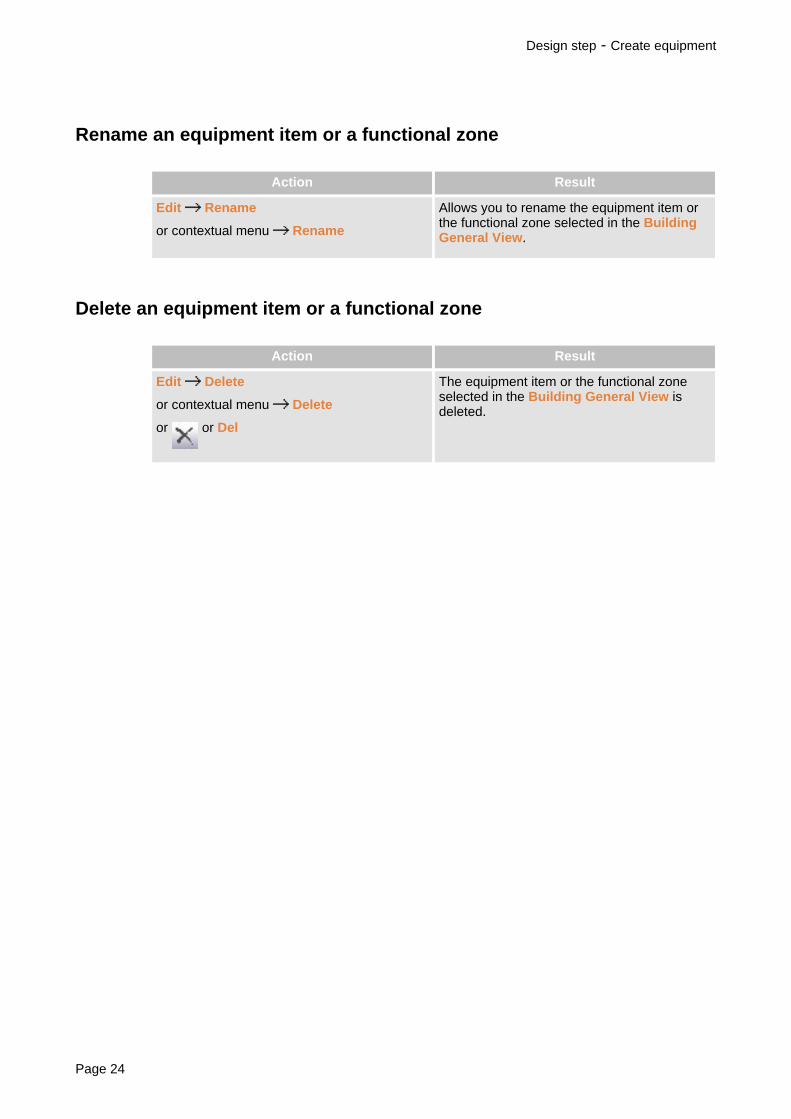
Rename an equipment item or a functional zone
Action Result
Edit Rename
or contextual menu Rename
Allows you to rename the equipment item orthe functional zone selected in the BuildingGeneral View.
Delete an equipment item or a functional zone
Action Result
Edit Delete
or contextual menu Delete
or or Del
The equipment item or the functional zoneselected in the Building General View isdeleted.
Design step - Create equipment
Page 24

Choice of equipment products
Presentation
There are several ways of adding products to the project.
You can look for a product by browsing through the catalogue contents or search for it from itspart number.
You can add products from your personal catalogue and products that are not referenced in thecatalogues.
You can access your favourite products quickly (list of favourites, preconfigured assemblies)and you can directly enter a part number in the product list.
You can copy products already existing in the project.
You can import products from former projects and projects created with Ecodial.
Once the product list has been drawn up, you can delete products from the list and modify thecharacteristics of the chosen products.
• Products can only be placed in equipment. Before choosing a product, select inthe Building General View the equipment item to receive it.
• Most actions can be undone (menu Edit Undo) and you can retroactivelyundo several actions.
Select products in catalogues
Search for products in the Schneider Electric electronic catalogue
In the electronic catalogue, you benefit from a large number of search functions (choice guides,search by part number, key word, etc.) and you can consult product documentation and viewproduct photos.
Detail of operations (p.28)
Direct search for Schneider Electric products
You can search for products by freely browsing in the Schneider Electric offer or use the searchby key word function.
Detail of operations (p.30)
Search for products in the personal catalogue
You can create your own database to save products not referenced in the catalogues deliveredwith the software. This database is your own personal catalogue. Initially it is empty and you willfill it according to your needs.
Detail of operations (p.31)
Modification of the personal catalogue (p.32)
Design step - Choice of equipment products
SISpro building 2.1 Page 25

Search for part numbers in catalogues
You can search for products from their part number in the Schneider Electric catalogues or inyour personal catalogue.
The products chosen from their part number are considered to be accessories andcannot be installed in the switchboard using automatic mounting tools. To be able touse installation in switchboard wizards, we recommend that you choose products bydirect access or in the electronic catalogue.
Search for a part number in the Schneider Electric catalogues (p.34)
Search for a part number in the personal catalogue (p.35)
Quick access
Search for products in the favourites
Favourites are a quick means of selecting products out of those you use most often. Initially thelist of favourites is empty and you will fill it according to your needs.
Detail of operations (p.36)
Modify the list of favourites (p.37)
Use of preconfigured assemblies
A preconfigured assembly is a product list that you save to use them again in the future, in thesame project or in other projects.
Preconfigured assemblies can be imported and exported to share them with other workstations.You can also import preconfigured assemblies created with old versions of the software.
When you retrieve a preconfigured assembly, only the product list is retrieved.
Choose a preconfigured assembly (p.38)
Create a preconfigured assembly (p.40)
Direct entry in the product list
If you know the part number of a product, you can enter it directly in the product list.
Detail of operations (p.41)
The other possibilities
Add a non referenced product
You can add to the product list a product that is non referenced in the catalogues.
Detail of operations (p.42)
Copy products
You can copy products in the product list. You can select several lines to copy them in a single
Design step - Choice of equipment products
Page 26

operation.
You can also copy only the devices of an equipment item, by deleting all the other products(functional units, distribution blocks, accessories, enclosures, etc.).
Detail of operations (p.43)
Import products
You can retrieve the products from projects completed using Schneider Electric software,Ecodial and SISpro building (versions 1.0, 1.1, 1.2, 1.3 and 2.0):
• In Ecodial projects you can select the components to be imported and import them intoequipment of the current project. The Ecodial project must have been exported using theECD format.
• In SISpro building projects you can select the equipment to be imported as well as theposition in which it will be imported in the structure of the current project.
Import an Ecodial project (p.44)
Import a SISpro building project (p.45)
Modify the list
Delete products
You can delete products from the product list. You can select several lines to delete them in asingle operation.
Secured products cannot be deleted directly in the Design step window. For moredetails, see Secured equipment (p.11).
Detail of operations (p.46)
Modify products
You can modify product characteristics, except for products selected in the personal catalogue.
Secured products cannot be directly modified in the Design step window. For moredetails, see Secured equipment (p.11).
Detail of operations (p.47)
Design step - Choice of equipment products
SISpro building 2.1 Page 27

Search for a product in the Schneider Electric electroniccatalogue
Action Result
Products Schneider Electric ElectronicCatalogue
or or SHIFT+F9
Opens the electronic catalogue
1. Search for the product:
• By part number or key word: select the relevant option in the Search menu, enter the partnumber or the key word in the Search field then press Enter.
• Using one of the wizards proposed in the Choice Guides menu.
• By browsing in the catalogue hierarchy in the left-hand part of the window.
The products chosen from their part number are considered to be accessoriesand cannot be installed in the switchboard using automatic mounting tools. To beable to use installation in switchboard wizards, we recommend that you chooseproducts by browsing in the catalogue hierarchy or using choice wizards.
2. Products are displayed in the right-hand part of the window. Double click on the relevantproduct to select it. The dialogue box presenting the product characteristics (p.29) appears.
3. Indicate the relevant quantity, select the product options and characteristics and click on theMemorise button.
4. According to the choices made, other dialogue boxes may appear. In these boxes select theproduct additional characteristics.
5. The Validation dialogue box appears, summarising the characteristics of the product chosen
6. Click on the button Add to List. The product is added to the product list and the Validationdialogue box closes, but the catalogue remains open to let you select other products.
Design step - Choice of equipment products
Page 28

Description of the product characteristics window
In the product characteristics choice window, the main characteristics are presented in lists.When you select a characteristic in a list, a small blue arrow appears above the list, showingthat the selected characteristic is frozen: selection of other characteristics cannot modify thischoice.
› To release a characteristic, click on the blue arrow.
› To re-initialise selections to catalogue default choices, click on the RESET button.
Design step - Choice of equipment products
SISpro building 2.1 Page 29

Direct search for Schneider Electric products
Action Result
Products Product direct access
or or F9
Opens the window Choose a product
When searching for a product, you can browse in the catalogue hierarchy or use search by keyword.
The offer hierarchy is displayed in the left-hand part of the catalogue window, while the productsare displayed in the right-hand part.
To browse in the offer:
1. Select an offer type in the list in the top left-hand corner. The offer contents appearunderneath.
2. Browse through the offer hierarchy, then click on the chapter containing the product you arelooking for.
To use the search function:
1. In the Search field at the top of the window, enter the key word to look for, then press Enter.The search result will appear in a dialogue box.
2. In the list Search results, double-click on a line to access the relevant product or chapter inthe catalogue.
To add a product to the project:
1. In the product list to the right, double click on the relevant product. The dialogue boxpresenting the product characteristics (p.29) will appear.
2. Indicate the relevant quantity, select the product options and characteristics, then click onthe Memorise button.
3. According to the choices made, other dialogue boxes may appear. In these boxes select theproduct additional characteristics.
4. When all the characteristics have been defined, the product is added to the product list, butthe catalogue remains open to let you select other products.
Design step - Choice of equipment products
Page 30

Choose a product in the personal catalogue
Action Result
Products Personal catalogue
or
Opens the window Choice of part numbers
1. In the Contents frame, click on the Manufacturer,the Family, then on the Chaptercontaining the part number you are looking for.
2. In the Part number frame, enter the relevant Quantity then double click on the part numberyou wish to add to the project. The product is added to the product list, but the catalogueremains open to let you choose other products.
The Define button provides access to the catalogue modification window. For moredetails, see Modify the personal catalogue (p.32).
Design step - Choice of equipment products
SISpro building 2.1 Page 31

Modify the personal catalogue
Action Result
Tools Modifying the personal catalogue
or Define button in the window Choice ofpart numbers
Opens the window Part number (p.33)
In the personal catalogue, part numbers are classed by manufacturer, product family andchapter. To add a part number, you must have created at least one manufacturer, one familyand one chapter.
To add a part number:
1. Click on the manufacturer for which you wish to create the part number. If there is none,create it using the Create button under the Manufacturer list.
2. Click on the family in which you wish to add the part number. If there is none, create it usingthe Create button under the Family list.
3. Click on the chapter in which you wish to add the part number. If there is none, create itusing the Create button under the Chapter list.
4. Click on the Create button in the Part number frame. The Part number dialogue box willappear.
5. Enter the information concerning the part number and click on OK.
To modify or delete a manufacturer, family, chapter or part number:
› Click on the line to be modified or deleted in the relevant list, then click on the Modify buttonor on the Delete button under the list.
When you delete a manufacturer, a family or a chapter, all its content will also bedeleted (e.g. if you delete a manufacturer, all the families, chapters and part numbersfor this manufacturer will be deleted).
Design step - Choice of equipment products
Page 32

Description of the Part Number window
Part number Product part number.
Description Product description.
Quantity by batch Quantity of products by packaging.
Price Part number price.
Workshop labour Labour required to install the products in the workshop. To beexpressed in hundredths of an hour.
Worksite labour Labour required to install the products on the worksite. To beexpressed in hundredths of an hour.
Height or length WidthDepth
To be expressed in millimetres. These dimensions arerequired for the part numbers you wish to install in theswitchboard. Products will be represented on the front paneldrawing in the form of a grey rectangle whose height andwidth are those entered here.
Internal part number Part number used internally, if different from the supplier'sone.
Type of vignette Used to specify the type of product. Products whose type ofvignette is Modular device or Terminal can be mounted on afunctional unit in the same way as Schneider Electric devices.
Design step - Choice of equipment products
SISpro building 2.1 Page 33

Search for a part number in the Schneider Electric catalogues
The products chosen from their part number are considered to be accessories andcannot be installed in the switchboard using automatic mounting tools. To be able touse installation in switchboard wizards, we recommend that you choose products bydirect access or in the electronic catalogue.
Action Result
Products Manufacturer part numbers Opens the window Choose a part number
1. In the Manufacturers list, select the catalogue containing the part number sought for.
2. In the Part number sought for field, enter the first characters of the part number, then clickon the Search button. The list of part numbers beginning with the characters enteredappears in the Part numbers table.
3. Click on the part number sought for in the table, then enter the relevant quantity in theQuantity field.
4. Click on OK. The part number is added to the product list, but the window Choose a partnumber continues to be displayed to let you look for other part numbers.
Displays the start of the catalogue, in alphanumerical order of part numbers
Displays the previous part number page
Displays the next part number page
Displays the end of the catalogue
Design step - Choice of equipment products
Page 34

Search for a part number in the personal catalogue
Action Result
Products Personal catalogue partnumbers
Opens the window Choose a part number
1. In the Part number field, enter the first characters of the part number sought for, then clickon the + button to display it. If there is one, it will appear in the table placed under the Partnumber field.
2. Enter the relevant quantity, then click on OK. The part number is added to the product list,but the window Choose a part number continues to be displayed to let you look for otherpart numbers.
Design step - Choice of equipment products
SISpro building 2.1 Page 35

Choose a product in the favourites
Action Result
Products Access to Favourites
or or F10
Opens the Favourites window
1. In the Categories list, click on the category containing the relevant product.
2. In the Switchgear list, click on the product, modify the quantity if required, then click on thebutton Add to basket.
3. Repeat steps 1 and 2 if you want to add other products to the basket.
4. When you have chosen all the products, click on OK to add them to the product list.
You can also view and modify the content of the basket by pressing Basket. TheBasket dialogue box will appear. The Validate basket button lets you add thebasket content to the product list, while the Previous button lets you return to thefavourites without adding products.
Design step - Choice of equipment products
Page 36
Modify the list of favourites
Action Result
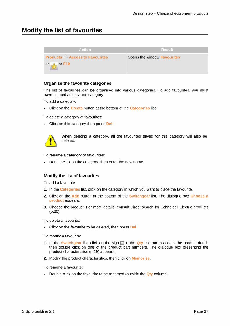
Products Access to Favourites
or or F10
Opens the window Favourites
Organise the favourite categories
The list of favourites can be organised into various categories. To add favourites, you musthave created at least one category.
To add a category:
› Click on the Create button at the bottom of the Categories list.
To delete a category of favourites:
› Click on this category then press Del.
When deleting a category, all the favourites saved for this category will also bedeleted.
To rename a category of favourites:
› Double-click on the category, then enter the new name.
Modify the list of favourites
To add a favourite:
1. In the Categories list, click on the category in which you want to place the favourite.
2. Click on the Add button at the bottom of the Switchgear list. The dialogue box Choose aproduct appears.
3. Choose the product. For more details, consult Direct search for Schneider Electric products(p.30).
To delete a favourite:
› Click on the favourite to be deleted, then press Del.
To modify a favourite:
1. In the Switchgear list, click on the sign in the Qty column to access the product detail,then double click on one of the product part numbers. The dialogue box presenting theproduct characteristics (p.29) appears.
2. Modify the product characteristics, then click on Memorise.
To rename a favourite:
› Double-click on the favourite to be renamed (outside the Qty column).
Design step - Choice of equipment products
SISpro building 2.1 Page 37

Choose a preconfigured assembly
Action Result
Products Choose a preconfiguredassembly
Opens the window Choose a preconfiguredassembly
1. In the drop-down list at the top of the window, click on the list containing the relevantpreconfigured assembly. The list Schneider Electric preconfigured assemblies containsthe predefined preconfigured assemblies, delivered with the software. The list Mypreconfigured assemblies contains the preconfigured assemblies that you have created.
2. In the list of preconfigured assemblies, click on the catalogue containing the relevantpreconfigured assembly, then on the preconfigured assembly. Information concerning thisassembly will appear in the information space at the bottom of the window: its name, thedate of creation, its type (graphic means that the preconfigured assembly is made up ofproducts installed in the switchboard).
3. Click on Add.
The list of preconfigured assemblies is organised into various categories. You can re-organisethe preconfigured assemblies within a category or change category by dragging them with themouse.
You can also:
• create new categories: detail of operations (p.38)• delete preconfigured assemblies and categories: detail of operations (p.38)• rename preconfigured assemblies and categories: detail of operations (p.39)
The Import button lets you import a preconfigured assembly created on other workstations,either with old software versions or with other Schneider Electric software. The Export buttonlets you export a preconfigured assembly to use it on other workstations or with other SchneiderElectric software.
Create a preconfigured assembly category
Categories can be fitted into one another.
1. Click on the category in which you want to create the new category, then click on CreateCategory.
2. Enter the category name, then press Enter.
Delete a preconfigured assembly or a category
› Click on the preconfigured assembly or the category that you want to delete, then click onDelete.
• When you delete a category, all the preconfigured assemblies classed in thiscategory will also be deleted.
• The first category at the top of the list cannot be deleted.
Design step - Choice of equipment products
Page 38

Rename a preconfigured assembly or a category
1. Click twice slowly on the preconfigured assembly or on the category that you want torename.
2. Enter the new name, then press Enter.
Design step - Choice of equipment products
SISpro building 2.1 Page 39

Create a preconfigured assembly
To create a preconfigured assembly, you must first select the products making up thisassembly.
To select several product lines (p.278)To select products installed in a switchboard (p.278)
Action Result
Products Create a preconfiguredassembly
Opens the window Create a preconfiguredassembly
1. In the drop-down list at the top of the window, click on My preconfigured assemblies. Thelist Schneider Electric preconfigured assemblies contains the predefined preconfiguredassemblies, delivered with the software, and cannot be modified.
2. In the list of preconfigured assemblies, click on the category in which you want to class thenew preconfigured assembly.
3. Click on Add.
4. Enter the name of the preconfigured assembly, then press Enter.
Preconfigured assemblies can be organised into several categories. Initially the list containsonly one category, but you can create others. Categories can be fitted into one another. Detailof operations (p.38)
You can also:
• Delete preconfigured assemblies and categories. Detail of operations (p.38)
• Rename preconfigured assemblies and categories. Detail of operations (p.39)
Design step - Choice of equipment products
Page 40

Enter a part number directly in the product list
1. Click on the empty line at the bottom of the list (Part number cell). The empty line isidentified by the character *.
2. Enter the part number, then press Enter.
Design step - Choice of equipment products
SISpro building 2.1 Page 41

Add a free part number
Action Result
Products Free part numbers Opens the window Create / Modify user partnumber
› Enter the quantity, part number, description, price and labour time of the product, then clickon OK.
Design step - Choice of equipment products
Page 42

Copy products
Standard copy
Action Result
Edit Copy then Paste
or contextual menu Copy then Paste
or then
Copies selected products
To select several product lines (p.278)To select products installed in a switchboard (p.278)
Copy devices
Action Result
Edit Copy then Paste Devices
or contextual menu Copy then PasteDevices
Copies only the devices of an equipment item(eliminates functional units, distributionblocks, accessories, enclosures, etc.)
1. In the Building General View, click on the equipment whose devices you want to copy, thenchoose Copy.
2. Click on the equipment in which you want to retrieve the copied devices, then choose Pastedevices.
Design step - Choice of equipment products
SISpro building 2.1 Page 43

Import an Ecodial project
Action Result
File Import products Import Ecodial Opens the window Import Ecodial
1. In the Source Project frame, click on Browse, then select the project to be imported (ECDformat). The list of components of the imported project will be displayed.
In the list, each line corresponds to a component. A circuit with several components appearson several lines. For each component, its functional name and the associated product aregiven. When the product is not included in the catalogues (product is too old for example),the line is displayed in blue.
2. Select the components that you want to import.
To select several lines (p.278)
3. In the Current Project frame, click on the equipment item to receive the imported product.
4. Click on the button . If, out of the imported products, some are not included in the
catalogues, the list of relevant components will be displayed.
Design step - Choice of equipment products
Page 44

Import a SISpro building project
Action Result
File Import products From a SISprobuilding project
Opens the window Import equipment from aSISpro building project
1. In the Source Project frame, click on Browse, then select the project to be imported. Theproject tree will be displayed.
2. Click on the equipment item you wish to import.
3. In the Current Project frame, click on the tree root or on the functional zone to receive theequipment.
4. Click on the button .
You can add other equipment items to be imported by repeating steps 2 to 4.
5. Click on OK to start import.
Design step - Choice of equipment products
SISpro building 2.1 Page 45

Delete products
Action Result
Edit Delete
or contextual menu Delete
or
Deletes selected lines
To select several lines (p.278)
Design step - Choice of equipment products
Page 46

Modify product characteristics
Action Result
Double-click on the product
or Contextual menu Modify / Consult
or F7
Displays product characteristics (p.29)
Design step - Choice of equipment products
SISpro building 2.1 Page 47

Cable equipment devices
Presentation
Once you have chosen the devices of an equipment item, you can define the electrical relationsbetween these devices, form groups and choose the group distribution blocks. The establishedhierarchical order will act as a guide to install products in the switchboard and the cablinginformation can be exported to diagram creation tools in order to automatically generate thewiring diagram of the equipment.
You can also assign devices functional names and descriptions, identify cross-links to otherequipment items and identify the devices having to be connected to terminals.
Cabling window
1. Tool bar2. Electrical relations : space in which you organise the electrical relations between devices
and form groups3. Space for entering functional names4. Space for entering functional descriptions5. Device group: group name possibly followed by the name of the group incoming device,
distribution block, list of group devices6. Device connected to terminals7. Link to another equipment item8. Unconnected devices: equipment devices that are not electrically connected
Design step - Cable equipment devices
Page 48

Products are represented by various icons:
device only
incoming device
group incoming unit
device group distribution block
device belonging to a group
device connected to terminal
link to another equipment item
• The Name and Description columns may be masked: click with the right buttonon the title of the columns, then click on the name of the column to be displayedor masked in the contextual menu.
• Column width may be modified.See Organisation of the SISpro building window (p.251)
Create electrical relations between devices
The equipment cabling hierarchy is defined in the space Electrical relations. To do this, movethe devices from the topic Unconnected devices to the topic Electrical relations by organisingthem according to the manner in which they must be connected.
› To move devices you can :
• drag them with the mouse,
• use the commands Cut/Paste (or Copy/Paste) in the Edit menu or in the contextualmenu,
• use the or buttons in the Cabling window toolbar.
When you move devices using the mouse, the mouse pointer takes on theappearance of a barred circle if the operation is not possible.
You can also delete devices and modify the characteristics of a product:
Action Result
Contextual menu Delete Deletes selected devices (wire devices arenot deleted but are moved up by one level)
Contextual menu Modify Product Modifies the characteristics of a product
Design step - Cable equipment devices
SISpro building 2.1 Page 49

• To select several devices (p.278)• When you add new products to the equipment, you can insert them directly in
their place in the electrical hierarchy: before choosing new products (see Choiceof equipment products (p.25)), click in the space Electrical relations on thedevice to which they must be connected.
Secured products cannot be modified or deleted directly in the Cabling window. Formore details, see Secured equipment (p.11).
Device grouping
A group is a set of mechanically and electrically associated devices. When mounting devices, allthe devices in a group will be mounted on the same functional unit.
Create a device group
When creating a group, the software analyses the devices to be grouped in order to propose aselection of distribution blocks to connect them.
In some cases, you may be proposed substitution of one device with another. If you accept theproposal, modify the device before recreating the group.
Action Result
Contextual menu Group and Choose theDistribution Block
or
Displays the window Create a Group
1. Use the mouse right button to click on the devices you want to group, then choose Groupand Choose the Distribution Block in the contextual menu. The window Create a Groupwill appear.
2. Enter the name of the group.
3. Choose the distribution block in the list proposed. The list contains only the distributionblocks that are compatible with the devices to be grouped. If you are not sure whichdistribution block you want to use, you can make this decision later on. Just choose theoption Without in the list. Once you have made your decision, you must modify the group inorder to define its distribution block. When the choice of distribution block is absolutelynecessary, the option Without is not proposed.
4. Click on Create. The window giving the distribution block characteristics (p.29) will appear.Only options compatible with the devices to be grouped are proposed (in particular the list ofavailable sizes).
5. Select the distribution block characteristics, then click on Memorise. The group is createdwith its distribution block and the grouped devices.
To select several devices (p.278)
Design step - Cable equipment devices
Page 50

Modify a device group
Action Result
Contextual menu Associate with anExisting Group Group name
The selected devices are associated with theindicated group (compatibility betweendevices and the group distribution block ischecked)
Contextual menu Modify the distributionblock
Changes the name of the group and thedistribution block
Contextual menu Separate from itsGroup
or
The selected devices are separated from thegroup
Contextual menu Separate Group The devices are separated and the group isdeleted
Del key The group and all the devices it contains aredeleted
• To select several devices (p.278)• To select an entire group, you can use Select the group in the contextual menu.
You can link a device to a device belonging to a group, but this device will not beincluded in the group. To associate a device with a group, you must use thecommand Associate with an Existing Group.
Functional names and descriptions
You can assign functional names and descriptions to devices to identify them on the wiringdiagram. Functional names are made up of 8 characters maximum (letters in capitals anddigits). A functional name must be unique and can only be assigned to one device of theequipment (but it can be used in other project equipment). Functional descriptions can containup to 30 characters (letters and digits).
Functional names can be entered manually or generated automatically and you can customisethe prefixes to be used during automatic generation.
Enter functional names and descriptions
Action Result
Products Automatic generation offunctional names
Automatically generates functional names forall equipment devices, except for those whosefunctional name was entered manually(functional names entered manually are notoverwritten during automatic generation)
Used to enter a functional name
Design step - Cable equipment devices
SISpro building 2.1 Page 51

To enter a functional name or description:
› Click in the Name column or in the Description column, then enter the functional name ordescription. End by pressing Enter.
To cancel the input, press Esc.
The options
Action Result
Configuration Functional names(Markers)
Used to define, for each device type, theprefixes to be used for automatic generationof functional names
Create a cross-link
A device can be identified as a component linking up to another device. Only terminal devices(with no connected devices) can have the status of a cross- link component.
Action Result
Contextual menu Cross-link component Designates a cross-link component or cancelsthe cross-link
To identify a cross-link component:
1. Click on the cross-link device with the mouse right button, then choose Cross-linkcomponent in the contextual menu. The window Start of cross-link to equipment willappear. It presents in a drop-down list all the project equipment except for the currentequipment.
2. Choose the cross-link target in the list.
3. Click on OK. The cross-link icon will appear next to the device and its functional descriptionis modified to indicate the cross-link target.
To link up to an equipment item external to the project, you can choose Otherequipment in the list and enter the name of the target equipment in the functionaldescription.
To cancel a cross-link:
› Click on the cross-link with the mouse right button. In the contextual menu appearing, a tickto the left of the command Cross-link component means that the device is identified as across-link. Click on Cross-link component. The tick is deleted and the cross-link cancelled.
Connection on terminal
The downstream connection point of protection devices may be transferred to power terminalsplaced in a peripheral zone of the switchboard. You can identify the devices having to beconnected to terminals.
Design step - Cable equipment devices
Page 52

Action Result
Contextual menu Transfer to terminal Used to establish or cancel alternately theconnection to terminal of the selected devices
To select several devices (p.278)
Print cabling information
Action Résultat
Print Used to print the cabling informationdisplayed in the window
Cabling information printout example
Design step - Cable equipment devices
SISpro building 2.1 Page 53

Page 54

Design of a Prisma Plusswitchboard
Presentation ........................................................................................................................... .56.Design window of a Prisma Plus switchboard ........................................................................ .57.Design methods of a Prisma Plus switchboard ...................................................................... .61.Guided design (Prisma Plus) ...................................................................................................63.Quick design (Prisma Plus) .................................................................................................... .65.Free design (Prisma Plus) ...................................................................................................... .67.Automatic placing in enclosure (Prisma Plus) ........................................................................ .68.Modify a Prisma Plus switchboard ....................................................................................... .100.The Prisma Plus switchboard views ..................................................................................... .103.Using the result (Prisma Plus switchboard) ...........................................................................106.To go further still ....................................................................................................................117.
Design of a Prisma Plus switchboard - Cable equipment devices
SISpro building 2.1 Page 55

Presentation
SISpro building offers a large number of wizards to guide you step by step through all thestages in production of complete configuration of a Prisma Plus switchboard. The mainfunctions available are:
• the possibility of managing an incoming device,• assistance with mounting devices on functionalised supports,• assistance with choice of switchboard architecture,• installation of products in wall mounted or floor standing enclosures,• automatic calculation of terminals,• calculation of available free rows,• calculation of labour times.
The result obtained depends on many parameters that you can adjust:
• switchboard general characteristics (nominal current, short-circuit current, degree ofprotection, required number of free rows, etc.)
• options for managing the incoming device,• options for mounting and connecting devices,• options for choosing terminals
etc.
Once the switchboard is complete, you can print and export the front panel drawing, the productpart numbers and the mounting document.
Action Result
in the tool bar or in the action bar of the
Design step
or double click on the equipment in theBuilding General View
Opens the window for design of a Prisma Plusswitchboard (an equipment of the typePrisma Plus switchboard must be selectedin the Building General View)
Design of a Prisma Plus switchboard - Presentation
Page 56

Design window of a Prisma Plus switchboard
1. Title bar (p.58)2. Menu bar (p.10)3. Tool bars (p.10)4. Message bar (p.58)5. Display space of the list Selected components (p.58) of theCabling tab (p.59). To display the
list Selected components, click on the button Selected components (9). To display theCabling, click on the button Cabling (10).
6. Space organised into 4 tabs:• Cabling tab (p.59)• Switchboard design tab (p.59)• Results tab (p.59)• Mounting document tab (p.60)
7. Display the characteristics of the component selected in the list Selected components, inthe cabling or in the drawing of the switchboard
8. Status bar (p.60)9. Button displaying the list of components10.Button displaying the cabling11.Decor palette (p.60)
Design of a Prisma Plus switchboard - Design window of a Prisma Plus switchboard
SISpro building 2.1 Page 57

You can mask the tool bars and the status bar, modify the distribution between thevarious window spaces and customise the menus and the tool bars. For datapresented in table form, you can also modify table column width.For more details, see Organisation of the Prisma Plus window (p.123) andCustomisemenus and tool bars (p.253).
Title bar
The title bar gives the name of the current action followed by the project name and the name ofthe equipment being processed. It contains, on the right, the standard buttons for placing as anicon, for reducing/enlarging and closing the window.
When the window is not displayed in full screen, you can move it by clicking in thetitle bar with the mouse and dragging it to another position.
Message bar
The message bar informs you of the reasons for refusal when you try to perform an impossibleoperation. It cannot be moved, but it can be hidden.
Selected components
This list presents the switchboard products divided into various topics. Each line corresponds toa single copy of a product (if the switchboard contains the same product in several copies, it willappear on several lines). Each product is represented by an icon and is identified by adescription. Icons are representative of the type of product (see detail below).
You can obtain more details on a product by leaving the mouse pointer a fewseconds on its description: the characteristics for this device then appear in a smallbubble.
Devices
This topic contains the devices and the device groups created during cabling (p.76) (with theirdistribution blocks), prior to mounting on functional units. Devices are represented by variousicons:
device
incoming device (p.70)
device group
device considered for calculation of terminals(p.79)
Terminals
This topic contains the feeder connection terminals.
Design of a Prisma Plus switchboard - Design window of a Prisma Plus switchboard
Page 58

Mounted devices
This topic contains the mounting functional units and the devices or device groups mounted(p.?) on these functional units.
Functional unit
Distribution block attached to the functionalunit (modular functional unit only)
Enclosures
This topic contains the wall mounted and floor standing enclosures, ducts, etc.
Distribution blocks
This topic contains the busbars and distribution blocks not included in a device group orattached to a modular functional unit.
Accessories
This topic contains accessories such as: earth/neutral busbar, cable tie-bar, etc. Accessorieshave no graphic representation and cannot appear in the switchboard drawing.
Cabling tab
In this tab you can define the electrical relations between switchboard devices, form devicegroups and choose group distribution blocks. The established hierarchical order may act as aguide to install products in the switchboard.
You can also assign devices functional names and descriptions, establish links with otherequipment and identify devices having to be connected to terminals.
For more details, see Cable devices for a Prisma Plus switchboard (p.76).
Switchboard design tab
This tab is a graphic space in which you assemble the various switchboard components (p.87)and create its front panel drawing. This tab has 4 pages. A single page is displayed at any onetime but you can easily change page (p.104) using two buttons in the tool bar. You can choosepage size and the title block for the sheet model (p.111).
Results tab
This tab presents, in table form, the following information:
Part nos. Part numbers of products, whether or not placed in theswitchboard drawing
Qty Quantity of each part number
Description Description associated with the part number in the catalogue
Status Products included in the list of Selected componentsProducts placed in the tab Switchboard design
Product Product description
Functional name Functional name associated with the product
Design of a Prisma Plus switchboard - Design window of a Prisma Plus switchboard
SISpro building 2.1 Page 59
You can sort the list of part numbers according to various criteria. The sort criteria correspond tothe table column titles:
› In the drop-down list Sort by, choose the relevant sort option or click on the title of thecolumn that you want to sort. The sorted column appears on a grey background.
By default, identical part numbers are grouped on the same line. You can cancel this groupingin order to view each part number separately by ticking the box Deploy part numbers.
When part numbers are grouped, the Status, Product and Functional namecolumns are not displayed.
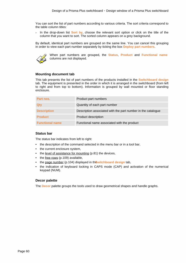
Mounting document tab
This tab presents the list of part numbers of the products installed in the Switchboard designtab. The equipment is presented in the order in which it is arranged in the switchboard (from leftto right and from top to bottom). Information is grouped by wall mounted or floor standingenclosure.
Part nos. Product part numbers
Qty Quantity of each part number
Description Description associated with the part number in the catalogue
Product Product description
Functional name Functional name associated with the product
Status bar
The status bar indicates from left to right:
• the description of the command selected in the menu bar or in a tool bar,• the current enclosure system,• the level of assistance for mounting (p.81) the devices,• the free rows (p.109) available,• the page number (p.104) displayed in theSwitchboard design tab,• the indication of keyboard locking in CAPS mode (CAP) and activation of the numerical
keypad (NUM).
Decor palette
The Decor palette groups the tools used to draw geometrical shapes and handle graphs.
Design of a Prisma Plus switchboard - Design window of a Prisma Plus switchboard
Page 60

Design methods of a Prisma Plus switchboard
To place in the switchboard the products of an equipment and to obtain its front panel, you canchoose one of the four methods described below.
In free design, you can freely browse through the steps of your choice. However, werecommend that you proceed in the order shown below, which corresponds to a logicswitchboard design order.
You can also be guided by one of the three design wizards.
The quick design wizard lets you produce a switchboard in only 3 steps. You can use thiswizard when you do not need to access the mounting and connection options or intervene in thedevice mounting order.
The guided design wizard will guide you step by step through all the possible steps and will letyou adjust a large number of parameters.
You can also begin switchboard design in the free mode, then end up by using the automaticplacing in enclosure wizard.
When producing a switchboard, messages may be displaced in the Messages (4(p.57)) bar. These messages are very useful for following progression of operationsand for understanding the many checks run by the software.
Design of a Prisma Plus switchboard - Design methods of a Prisma Plus switchboard
SISpro building 2.1 Page 61

Actions Guideddesign (p.63)
Quick design(p.65)
Free design(p.67)
Automaticplacing in
theenclosure
(p.?)
Choice of products for aPrisma Plus switchboard(p.?)
1 1 1
Manage the incoming device(p.70)
2
Definition of characteristicsfor a Prisma Plus switchboard(p.71)
2 2 3
Mounting and connectionoptions (p.73)
4
Configure choice of terminals(p.74)
5
Cable devices for a PrismaPlus switchboard (p.76)
3 6
Device mounting order (p.78) 4 7Calculate power terminals(p.?)
5 3 8 1
Mount devices on functionalunits (p.81)
9
Choice of switchboardarchitecture (p.85)
6 10
Install products in a PrismaPlus switchboard (p.87)
11
Finishing the Prisma Plusswitchboard (p.98)
12
Modify a Prisma Plusswitchboard (p.100)
13
Design of a Prisma Plus switchboard - Design methods of a Prisma Plus switchboard
Page 62

Guided design (Prisma Plus)
The guided design wizard will guide you step by step through all the possible steps and will letyou adjust a large number of parameters.
When producing a switchboard, messages may be displaced in the Messages bar (4(p.57)). These messages are very useful for following progression of operations andfor understanding the many checks run by the software.
Actions Guided design
Choice of products for a Prisma Plus switchboard(p.69)
1
Manage the incoming device (p.70)
Definition of characteristics for a Prisma Plusswitchboard (p.71)
2
Mounting and connection options (p.73)
Configure choice of terminals (p.74)
Cable devices for a Prisma Plus switchboard(p.?)
3
Device mounting order (p.78) 4Calculate power terminals (p.79) 5Mount devices on functional units (p.81)
Choice of switchboard architecture (p.85) 6Install products in a Prisma Plus switchboard(p.?)
Finishing the Prisma Plus switchboard (p.98)
Guided design - Step 1 - Choice of devices
In this step you can manage one device differently from the others: the incoming device. Thisdevice is treated specifically during installation in the switchboard. It can be managedautomatically or you can designate it yourself.
You can also modify the product list. You can add products, copy or delete devices and modifythe characteristics of the selected devices.
Fore more details, see:
• Choice of products for a Prisma Plus switchboard (p.69)• Manage the incoming device (p.70)
Guided design - Step 2 - Switchboard characteristics
In this step you must define the general characteristics of the switchboard and choose theenclosure range.
You can also request automatic management of terminal groups for downstream deviceconnection and have access to the device mounting and connection parameters and to theterminal choice parameters.
Design of a Prisma Plus switchboard - Guided design (Prisma Plus)
SISpro building 2.1 Page 63

For more details, see:• Definition of characteristics for a Prisma Plus switchboard (p.71)• Mounting and connection options (p.73)• Configure choice of terminals (p.74)
Guided design - Step 3 - Cabling
In this step you can define the electrical relations between devices. You have the possibility ofgrouping devices so that they are mounted on the same functional mounting plate.
For more details, see: Cable devices for a Prisma Plus switchboard (p.76)
Guided design - Step 4 - Device mounting order
In this step, you can organise devices in the order required to install them in the switchboard.You have 4 automatic sort options: in cabling order, in product choice order, by device rating orby cabling level.
You can also move devices by dragging them to various points using the mouse.
For more details, see: Device mounting order (p.78)
Guided design - Step 5 - Calculating terminals
If the Automatic calculation of terminals option was selected in the switchboardcharacteristics (step 2), the number of terminals required to connect the downstream devices iscalculated and the relevant equipment is added to the product list. If you have chosen tomanage an incoming device, it will be excluded from terminal calculation.
The wizard then determines the functional mounting plates required to install the devices andplaces the devices and terminals on these functional units.
For more details, see:
• Calculate power terminals (p.79)• Mount devices on functional units (p.81)
Guided design - Step 6: Placing in enclosure proposals
In this step, the wizard offers you a choice of wall mounted and floor standing enclosures thatcan contain products and, once you have selected the solution best for you, it determines themounting and connection accessories. It then finishes the switchboard by installing the productsin the chosen wall mounted or floor standing enclosures, then automatically completes the frontpanel with plain front plates.
For more details, see:
• Choice of switchboard architecture (p.85)• Install products in a Prisma Plus switchboard (p.87)• Finishing the Prisma Plus switchboard (p.98)
Design of a Prisma Plus switchboard - Guided design (Prisma Plus)
Page 64

Quick design (Prisma Plus)
The quick design wizard will let you produce a switchboard in only 3 steps. You can use thiswizard when you do not need to access the mounting and connection options or intervene onthe device mounting order.
When producing a switchboard, messages may be displaced in the Messages (4(p.57)). These messages are very useful for following progression of operations andfor understanding the many checks run by the software.
Actions Quick design
Choice of products for a Prisma Plus switchboard(p.69)
1
Manage the incoming device (p.70)
Definition of characteristics for a Prisma Plusswitchboard (p.71)
2
Calculate power terminals (p.79) 3Mount devices on functional units (p.81)
Choice of switchboard architecture (p.85)
Install products in a Prisma Plus switchboard(p.?)
Finishing the Prisma Plus switchboard (p.98)
Quick design - Step 1 - Choice of devices
In this step you can manage one device differently from the others: the incoming device. Thisdevice is treated specifically during installation in the switchboard. It can be managedautomatically or you can designate it yourself.
You can also modify the product list. You can add products, copy or delete devices, modify thecharacteristics of the selected devices and re-organise the list in the required mounting order fordevices.
For more details, see:
• Choice of products for a Prisma Plus switchboard (p.69)• Manage the incoming device (p.70)
Quick design - Step 2 - Switchboard characteristics
In this step you can define the general characteristics of the switchboard and choose theenclosure range.
For more details, see: Definition of characteristics for a Prisma Plus switchboard (p.71)
Quick design - Step 3 : Placing in enclosure proposals
If the Automatic calculation of terminals option was selected in the switchboardcharacteristics (step 2), the number of terminals required to connect the downstream devices iscalculated and the relevant equipment is added to the product list. If you have chosen tomanage an incoming device, it will be excluded from terminal calculation.
The wizard then determines the functional mounting plates necessary to install the devices andplaces the devices and terminals on these functional units. It then offers you a choice of wall
Design of a Prisma Plus switchboard - Quick design (Prisma Plus)
SISpro building 2.1 Page 65

mounted and floor standing enclosures that can contain products and, once you have selectedthe solution best for you, it determines the mounting and connection accessories. It thenfinishes the switchboard by installing the products in the chosen wall mounted or floor standingenclosures, then automatically completes the front panel with plain front plates.
For more details, see:
• Calculate power terminals (p.79)• Mount devices on functional units (p.81)• Choice of switchboard architecture (p.85)• Install products in a Prisma Plus switchboard (p.87)• Finishing the Prisma Plus switchboard (p.98)
Design of a Prisma Plus switchboard - Quick design (Prisma Plus)
Page 66

Free design (Prisma Plus)
In free design, you can freely browse through the steps of your choice. However, werecommend that you proceed in the order shown below, which corresponds to a logicswitchboard design order.
When producing a switchboard, messages may be displaced in the Messages (4(p.57)). These messages are very useful for following progression of operations andfor understanding the many checks run by the software.
Actions Free design
Choice of products for a Prisma Plus switchboard(p.69)
1
Manage the incoming device (p.70) 2Definition of characteristics for a Prisma Plusswitchboard (p.71)
3
Mounting and connection options (p.73) 4Configure choice of terminals (p.74) 5Cable devices for a Prisma Plus switchboard(p.?)
6
Device mounting order (p.78) 7Calculate power terminals (p.79) 8Mount devices on functional units (p.81) 9Choice of switchboard architecture (p.85) 10Install products in a Prisma Plus switchboard(p.?)
11
Finishing the Prisma Plus switchboard (p.98) 12Modify a Prisma Plus switchboard (p.100) 13
Design of a Prisma Plus switchboard - Free design (Prisma Plus)
SISpro building 2.1 Page 67

Automatic placing in enclosure (Prisma Plus)
You can use the automatic placing in enclosure wizard to finish switchboard mounting. Thiswizard automatically links up all the installation in the switchboard steps of equipment products.
When producing a switchboard, messages may be displaced in the Messages (4(p.57)). These messages are very useful for following progression of operations andfor understanding the many checks run by the software.
Actions Automatic placing inenclosure
Calculate power terminals (p.79) 1Mount devices on functional units (p.81)
Choice of switchboard architecture (p.85)
Install products in a Prisma Plus switchboard(p.?)
Finishing the Prisma Plus switchboard (p.98)
Design of a Prisma Plus switchboard - Automatic placing in enclosure (Prisma Plus)
Page 68

Choice of products for a Prisma Plus switchboard
Presentation
You can add products to the switchboard during its production. For this you can use most of themethods designed to add products to equipment: search in catalogues, search by part number,search in favourites, use of preconfigured assemblies, addition of products not referenced in thecatalogues, copy of switchboard products. You can also delete products and modify the chosenproduct characteristics..
Below are comments on use of preconfigured assemblies and a description of a quick methodto delete products from the list of Selected components. For more details on the otherpossibilities, refer to Choice of equipment products (p.25).
Use of preconfigured assemblies
Preconfigured assemblies can be used to create switchboards quickly. You can save in the formof preconfigured assemblies parts of switchboards and even complete switchboards. Forexample, you can save in a preconfigured assembly a fully installed column. To create a newswitchboard, you must retrieve this preconfigured assembly that you will use as a starting baseand then complete the installation manually or using the software wizards.
A preconfigured assembly can be created from components selected in the list of Selectedcomponents, in the Cabling, or in the Switchboard design tab. When you retrieve apreconfigured assembly:
• the original components in the list of Selected components are replaced in this list, in theappropriate topic,
• the original components in the Switchboard design tab are replaced in this tab,• for original components of Cabling, the electrical relations are saved.
Delete products from the list of Selected Components
You can delete products from the list of Selected components by selecting one or moreproducts in the same topic or in different topics, then by using the standard deletion commands(Del key or Delete command). However, you also have a specific function allowing you to deleteall the products in a topic:
1. Click on the topic from which you wish to delete products with the right mouse button, thenchoose Delete components in the contextual menu.
2. A confirmation message will appear. Choose Yes.
If this is the Mounted devices topic, a second message will appear. Choose No.If you choose Yes, the devices are not deleted but are sent to the Selectedcomponents topic. For more details, see Remove the devices from a functionalunit (p.83).
Design of a Prisma Plus switchboard - Automatic placing in enclosure (Prisma Plus)
SISpro building 2.1 Page 69

Manage the incoming device
Presentation
You can manage one device differently from the others: the incoming device. This device:
• is treated in a specific manner during mounting on functional units (p.81) and installation(p.?) in the switchboard,
• is excluded from calculation of terminals (p.79),• is identified by a specific icon.
To designate the incoming device, you can:
• Let the wizard act. In this case, the device with the highest rating is systematicallydesignated as the incoming device.
• Manually designate one of the switchboard devices. In this case, this device remains theincoming device until you designate another, even if you add a device with a higher rating tothe switchboard.
Choose mounting and installation options
Option Where
Mounting and connection options See Mounting and connection options (p.73)
Mounting the incoming device
The incoming device can be mounted by itselfon a functional unit or on a dedicated rail andby itself in a dedicated cubicle. When theincoming device is installed by itself in adedicated cubicle and does not take up theentire height of the cubicle, supports for HSI(p.93) can be placed at the top of the cubicle.
Configuration Configure applicationtab Mounting (p.120)
Designate the incoming device
To activate incoming device management:
› In the switchboard characteristics (p.71), on the lineIs there an incoming device? click onYes.
To manually designate the incoming device:
1. In the list of Selected components, click on the device that you want to designate as theincoming device.
2. In the Wizard menu or in the contextual menu, choose Choice of incoming device.
Design of a Prisma Plus switchboard - Automatic placing in enclosure (Prisma Plus)
Page 70

Definition of characteristics for a Prisma Plus switchboard
Presentation
One of the first steps in switchboard production consists of:
• defining the configuration initial parameters (electrical characteristics, required number offree rows, type of partitioning for cubicles, type of doors, enclosure range),
• specifying whether terminals must be calculated and whether the incoming device must bemanaged,
• defining the mounting and connection options and the choice of terminals.
Switchboard electrical characteristics
These are the electrical characteristics entered on equipment creation, that you can modify ifnecessary:
• Switchboard nominal current• Short-circuit current at the incoming point• Required degree of protection
Free rows
Free rows represent the space that you wish to keep available in the switchboard to installfuture items of equipment. This space is given as a percentage.
For more details, see View the free row percentage in a Prisma Plus switchboard (p.109).
Cubicle partitioning
You can choose a level of protection for products when they are mounted in the cubicle. Form 1corresponds to the lowest protection and Form 3 to the highest protection.
Horizontal partitioning between modular functional units may be required for form 3.See option Generate partitionings between modular FUs in the configureapplication tab Installation (p.121).
Type of door
Choice of door proposed depends on the switchboard IP.
Manage terminals
When this option is selected, the automatic design wizards include the terminal calculation step.For more details, see Calculate power terminals (p.79).
Manage incoming device
When this option is selected, the software distinguishes the incoming device from the otherdevices. For more details, see Manage the incoming device (p.70).
Choice of enclosure range
The enclosure ranges proposed depend on the characteristics and options selected.
Design of a Prisma Plus switchboard - Automatic placing in enclosure (Prisma Plus)
SISpro building 2.1 Page 71

If you choose the Wall mounted enclosure/Floor standing enclosure range or theCubicle range, the corresponding sheet model is automatically selected.For more details, see the option: Sheet model in the configure application tabDisplay (p.119).If you choose the PACK range, all the functions concerning device mounting (p.81)on functional units are de-activated and the Mounted devices topic is deleted fromthe list of Selected components. If this topic contains mounted devices, a messagewill appear. You can then:• Either re-initialise the configuration, in which case only the switchgear is kept:
products are disassembled and placed in the Devices topic and the functionalunits are deleted.
• Or keep everything, in which case the products are disassembled and placed inthe Devices topic and the functional units are placed in the Accessories topic. Inthis case, if you choose another range at a later stage, the functional units arereplaced in the Mounted devices topic.
Define the switchboard characteristics
Action Result
Equipment Switchboard characteristics
or Guided and quick design wizards: Step 2
Displays the switchboard characteristics
Design of a Prisma Plus switchboard - Automatic placing in enclosure (Prisma Plus)
Page 72

Mounting and connection options
The mounting and connection options affect the progression of operations during devicemounting (p.81) on functional units. Two series of parameters can be defined, one used only tomount the device designated as the incoming device, and the other used to mount all the otherdevices.
Action Result
Switchboard characteristics - buttonIncoming device
or Configuration Incoming devicemounting and connections
or Configuration Configure application -tab Mounting (p.120) - ButtonIncoming device
Opens the window Modify connectionfamilies for the incoming device (p.70)
Switchboard characteristics - button Standarddevices
or Configuration Standard mountingand connections
or Configuration Configure application -tab Mounting (p.120) - ButtonStandarddevices
Opens the window Modify connectionfamilies for all devices other than theincoming device
The Default button is used to save the options that you have just defined for use inyour future projects.
Design of a Prisma Plus switchboard - Automatic placing in enclosure (Prisma Plus)
SISpro building 2.1 Page 73

Configure choice of terminals
Presentation
If you want to use the terminal calculation wizard (p.79), you need to define the various optionsinvolved in this calculation:
• the type of cable used by default• the terminals to be used for each device rating• the possible cable types
Predefined tables are supplied with the software, but you can add new cable types, modifyterminal section/rating associations and choose the relevant terminals in the Schneidercatalogues or in your personal catalogue.
Choose the options
Action Result
Switchboard characteristics - buttonConfigure choice of terminals
or Configuration Configure choice ofterminals
or Configuration Configure application -tab Terminals (p.122) -Configure button
Opens the window Configure choice ofterminals
Choose the type of default cable
The type of default cable is used to calculate terminals when the terminal calculation wizardwindow is not displayed. For more details, see Calculate power terminals (p.79).
› In the list Type of cable of the In/S tab, click on the type of cable required, then click onTable used by default.
Choose the terminals
For each terminal section, you must specify the products you want to use. Terminals can bechosen in the Schneider catalogues or in your personal catalogue.
1. Click on the tab Terminal supplier.
2. For each terminal section:
a. Click in the Choice of catalogue column. A small arrow will appear to the right.
b. Click on the arrow, then click on the relevant catalogue in the list. The catalogueconsultation window will appear.
c. Choose the terminal in the catalogue (for more details, see Direct search for SchneiderElectric products (p.30) or Choose a product in the personal catalogue (p.31)). Thechosen product description appears in the Terminal column.
3. When all the terminals have been defined, click on OK.
Design of a Prisma Plus switchboard - Automatic placing in enclosure (Prisma Plus)
Page 74

Modify the terminal sections
You can define the terminal section that you want to use for each nominal current range and foreach type of cable.
1. In the list Type of cable of the In/S tab, select the type of cable to be configured.
2. For each range to be defined:
a. Click in the In Max. column and enter the value of the upper limit of the range. A new lineis immediately created below for the next range with as In Min. the value immediatelyabove.
b. Click in the Associated terminal section column. A small arrow will appear to the right.Click on this arrow, then on the relevant section in the list brought up.
For the last range, select a cable section, but leave the In Max value empty.
3. Repeat steps 2 and 3 for each cable type.
4. When the terminal sections have been defined for each cable type, click on OK.
Modify the cable types
A certain number of cable types are predefined in the software (copper, aluminium), but you canadd others or remove those you do not use:
› In the In/S tab, click on the button Add/modify a cable type, then use the Add and Removebutton without the dialogue box Add a type.
Design of a Prisma Plus switchboard - Automatic placing in enclosure (Prisma Plus)
SISpro building 2.1 Page 75

Cable devices for a Prisma Plus switchboard
Presentation
You can define the electrical relations between devices, form device groups and choose groupdistribution blocks. The hierarchical order established may act as a guide to install the productsin the switchboard.
You can also assign devices functional names and descriptions, establish links to otherequipment and identify the devices having to be connected to terminals. In a Prisma Plusswitchboard, you can also create motor feeder groups.
You can establish electrical relations between devices either in the Cabling (6 (p.57)) tab or inthe Cabling (5 (p.57)) section that you can display instead of the list of Selected components.
Action Result
Display Cabling
or click on the tab name or F5
Displays the Cabling tab
Click on the Cabling button (10 (p.57)) at thebottom of the list of Selected components
The Cabling replaces the list of Selectedcomponents
Design of a Prisma Plus switchboard - Automatic placing in enclosure (Prisma Plus)
Page 76

Detail of the operations
The creation of a motor feeder group is described below. For the detail of the other operations,refer to Cable equipment devices (p.48).
Create the motor feeder group
This type of grouping is dedicated to specific cases. It enables grouping of products that can beinter-connected mechanically. When the group is created, instead of choosing a distributionblock, selection of the connection part will be proposed. To create this type of group, bothdevices must be electrically connected so that one is the child of the other.
Action Result
Contextual menu Create motor feedergroup
or
Displays the window Create a Group
1. Connect the two devices making up the group so that one is the child of the other. Forexample, for a motor feeder made up of a Tesys GVL2 circuit-breaker and a Tesys LC1Dcontactor, the contactor must be the child of the circuit-breaker.
2. Select the two connected devices, then choose Create motor feeder group in thecontextual menu. The Create a Group window will appear.
3. Enter the group name.
4. In the list Compatible association blocks, select the relevant part number. You can chooseWithout if you do not want a connecting part.
5. Click on Create.
Design of a Prisma Plus switchboard - Automatic placing in enclosure (Prisma Plus)
SISpro building 2.1 Page 77

Device mounting order
Presentation
The devices will be installed in the order of the list of Selected components. It is thus importantto define the order of this list before starting to mount.
You can organise the list of components manually or use the automatic sort functions.
Sort devices automatically
Action Result
Products Sort selected components 3 sort modes:
• in cabling order• by cabling level• by device rating
Guided design wizard - Step 4 4 sort modes:
• in cabling order• in product choice order• by device rating• by cabling level
Move devices manually
› To move devices in the list of Selected components, use the Cut and Paste commands inthe Edit menu or drag them using the mouse.
Design of a Prisma Plus switchboard - Automatic placing in enclosure (Prisma Plus)
Page 78

Calculate power terminals
Presentation
The downstream connection point of the protective devices may be transferred to powerterminals placed in a peripheral zone of the switchboard that is easily accessible. A wizard willlet you automatically calculate the number of terminals required for configuration as whole andadds the relevant products to the product list.
The calculation takes into account all the end modular devices of the switchboard (except forthe incoming device and group incomers), but only the electrically connected devices if thecabling (p.48) has been done. Devices for which terminals cannot be determined correctly areignored.
For each device considered, the wizard determines the group of terminals attached to it. Thenumber and size of terminals are calculated below:
• the rating (In) and the number of poles of the devices,• the type of cable used,• the types of terminals defined in the configuration for the various device ratings.
After the calculation, you can add additional terminals by choosing them in the catalogues.These terminals are added to the terminals calculated.
The terminals are placed in the Terminals topic of the list of Selected components and thedevices connected to terminals are identified by a specific icon in the list of Selectedcomponents and in the Cabling window.
The terminals can be calculated for the entire switchboard or for isolated devices.
Choice of options
Options Where
Types of cable
Type of default cable
Types of terminal
See Configure choice of terminals (p.74)
Calculate terminals for the entire configuration
Action Result
Wizard Calculate terminals Opens the window Calculate terminals
If the switchboard already contains terminals, a message asks you whether you wantto keep them. To recalculate the terminals, choose No. If you choose Yes, theexisting terminals are kept and the calculation is cancelled.
1. In the top list, select the type of cable. The table below presents the number of terminalscalculated for each cross-section of this type of cable.
2. Click on Launch choice of terminals. The terminals are added to the product list.
Design of a Prisma Plus switchboard - Automatic placing in enclosure (Prisma Plus)
SISpro building 2.1 Page 79

The Calculate terminals window may not appear (see Display of dialogue boxesin the configure application tab Display (p.119)). In this case, the calculation islaunched for this type of cable defined by default.
Calculate terminals for a device
1. In the list of Selected components, select the devices for which you wish to calculate theterminals.
2. Choose Calculate terminals in the contextual menu.
Design of a Prisma Plus switchboard - Automatic placing in enclosure (Prisma Plus)
Page 80

Mount devices on functional units
Presentation
Some devices, said to be functionalised, can be installed on suitable supports known asfunctional units. Mounting consists of choosing the necessary functional units and placing thedevices on these functional units.
The mounting wizard performs this operation automatically with various checking levelsaccording to the chosen options. It automatically selects the necessary functional units, theninstalls the devices, grouping them on the same functional unit whenever possible.
You can also manually mount devices on an existing functional unit.
• In the PACK range (p.91), the devices are placed directly on the enclosuremodular rails: there is thus no mounting on functional units.
• The personal catalogue products whose type of vignette is Modular device orTerminal can be mounted on functional units.For more details, see Modify the personal catalogue (p.32) and Description of thePart Number window (p.33), Type of vignette fields.
Choice of options
Option Where
For automatic mounting wizards:
Level of assistance
• Detailed: you will validate step by stepmounting of each device and check eachchoice proposed by the software.
• Assisted: your intervention will berequired to validate certain mountingoptions.
• Automatic: mounting is performedautomatically, without any action on yourpart.
The level of assistance is indicated in thestatus bar (8 (p.57)).
Configuration Configure application -tab Mounting (p.120)
Mounting and connection options See Mounting and connection options (p.73)
Positioning the distribution blocks
Device default mixing
Configuration Configure the applicationtab Mounting (p.120)
Design of a Prisma Plus switchboard - Automatic placing in enclosure (Prisma Plus)
SISpro building 2.1 Page 81

Use the mounting wizard
Action Result
Wizard Mounting the selected devices Opens the window Mounting a list ofdevices
1. Check device selection, then click on Validate.
The Mount a list of devices window may not appear (see Display of dialogueboxes in the configure application tab Display (p.119)). In this case, all the devicesin the list of Selected components are mounted.
You can also:• Select (p.278) the devices to be mounted in the list ofSelected components (to
mount all the devices in this list this selection is not necessary, then chooseMount in the Products menu or in the contextual menu.
• Or select (p.278) the devices to be mounted in the list ofSelectedcomponents, then drag them with the mouse and place them on the title ofthe Mounted devices topic.
2. The remainder of the operations depends on the selected mounting mode. See belowDetailed mounting, Assisted mounting, Automatic mounting.
3. At the end of processing, if some devices could not be mounted, a report will summarise thereasons for this in each case.
During mounting, a progression bar indicates the progression status of theprocessing. You can cancel mounting by clicking on the Undo button placed underthe progression bar.
Detailed mounting
For each functional unit to be created, a dialogue box presenting the characteristics (p.29) formounting appears. Choose the relevant options, then click on Memorise. The system will moveto the next functional unit.
If you click on Undo, the Undo mounting window will appear. It lets you cancel either onlycurrent device mounting or mounting as a whole. Choose the relevant option, then click on OK.
The Undo mounting window may not appear. For more details, see Display ofdialogue boxes in the configure application tab Display (p.119).
If, for a device, no mounting solution can be proposed, a message appears proposing that youmodify the device characteristics. Choose Yes. The dialogue box presenting the characteristics(p.29) of the device appears. Choose the new characteristics then click on Memorise.
Assisted mounting
For each functional unit to be created, the mounting characteristics are determinedautomatically by the software according to the device and the mounting and connection options(p.73).
Design of a Prisma Plus switchboard - Automatic placing in enclosure (Prisma Plus)
Page 82

If, for a device, no mounting solution can be proposed, a dialogue box appears to indicate thecause of the conflict. After consultation, click on OK to continue. The dialogue box presentingthe characteristics (p.29) for device mounting appears to allow you to choose anotherconnection solution. Choose the mounting options, then click on Memorise.
Automatic mounting
Mounting is performed fully automatically, including when the connection default configuration isnot suitable. In this case, the wizard choses other mounting options.
Mount devices on an existing functional unit
Mounting is possible only if the functional unit is compatible with the devices and if it hassufficient space. If there is no mounting solution, a message will warn you of this and mountingwill be cancelled.
› In the list of Selected components, select (p.278) the devices to be mounted, then drag themwith the mouse and place them in the Mounted devices topic on the functional unit on whichyou want to mount them.
Please note
• If you select a comb busbar or a distribution block in the characteristics of a modularfunctional unit, the chosen distribution block will appear in the Mounted devices sectionunder the functional unit.
• If you mount a device group (p.50) on an existing functional unit, the distribution block of thefunctional unit is replaced by that of the group.
• When you mount a device group (p.50) without a distribution block on a functional unitcontaining a distribution block and on which non-grouped devices are mounted, thefunctional unit moves to the wire to wire mode.
Remove the devices from a functional unit
You can remove the devices from the functional units on which they are mounted. Thedisassembled devices are sent back to the Devices topic in the list of Selected components.
The devices can be disassembled selectively, but you can also disassemble all together all thedevices of the Mounted devices section and delete the functional units and mountingaccessories found in this topic.
When you disassemble all the device groups of a functional unit, the functional unitmoves to wire to wire mode.
Unmount the selected devices
1. In the topic Mounted devices, select (p.278) the devices that you want to unmount. You canselect several devices on the same functional unit or on various functional units. You canalso select several functional units to unmount all the devices found on these functionalunits.
2. In the Products menu choose Unmount.
Design of a Prisma Plus switchboard - Automatic placing in enclosure (Prisma Plus)
SISpro building 2.1 Page 83

You can also unmount the devices of a functional unit by dragging them with themouse and placing them on the title of the Devices topic.
Unmount all the mounted devices
1. In the list of Selected components, click on Mounted devices with the mouse right button,then choose Delete components in the Contextual menu.
2. A message appears. Click on Yes.
3. A second message appears. Click on Yes.
If you click on No for the second question, the devices will be deleted.For more details, see Delete products from the list of Selected Components (p.69).
Design of a Prisma Plus switchboard - Automatic placing in enclosure (Prisma Plus)
Page 84

Choice of switchboard architecture
Presentation
To help you choose the switchboard architecture, you have at your disposal a placing inenclosure wizard. This wizard offers you a choice of wall mounted and floor standing enclosuresthat can contain products, then once you have selected the right solution for you, it determinesthe mounting and connection accessories and adds the enclosure and the accessories to thelist of Selected components. You can then install (p.87) the enclosures in theSwitchboarddesign. tab.
To determine the possible architectures, the wizard takes into account:
• the switchboard characteristics (p.71) (IP, In, Isc, Form, Range, Free rows, Use of terminals)
• the devices in the Mounted devices topic in the list of Selected components (or thecompatible devices in the Devices topic in PACK range)
• the options chosen for the busbars
Choice of options
Option Where
Choice of switchboard architecture
Filtering possible solutions
Configuration Configure the applicationtab General (p.119)
Powerclip busbar
Phases
Configuration Configure the applicationtab Busbars (p.122)
Use the wizard
Action Result
Wizard Choice of switchboardarchitecture
Displays the window Choice of switchboardarchitecture
• If the list of Selected components already contains enclosures, distributionblocks and accessories, a message proposes that you delete or keep theseproducts.
• If there are devices not mounted in the list of Selected components, a messagewill inform you. Click on Yes to mount these devices before continuing installationin the enclosure or on No to continue installation in the enclosure without thesedevices.
The Choice of switchboard architecture window presents:
• to the right, a graphic representation of the various solutions proposed,• to the left, the number of solutions proposed, a reminder of the switchboard characteristics
Design of a Prisma Plus switchboard - Automatic placing in enclosure (Prisma Plus)
SISpro building 2.1 Page 85

and the characteristics of the selected solution to the right. The More info button lets youcalculate the switchboard dimensions and the free rows actually available (p.109).
1. Click on one of the solutions proposed to the right to select it, then click on the Validatebutton.
If you have chosen a solution with busbar, the dialogue box Configure Busbarsmay appear to allow you to specify the number of phases of the busbars. Choosethe number of phases required then click on OK. If this dialogue box does notappear (see Display of dialogue boxes in the configure application tab Display(p.119)), the number of phases considered is that entered in the applicationconfiguration.
2. Enclosures and installation accessories are added to the list of Selected components.
Design of a Prisma Plus switchboard - Automatic placing in enclosure (Prisma Plus)
Page 86

Install products in a Prisma Plus switchboard
Presentation
You have a graphic space (Switchboard design tab) in which you can assemble theswitchboard and obtain the drawing of its front panel. Installation consists of placing theenclosures in the drawing space, then storing the products inside the enclosures.
The drawing space contains 4 pages. Only one page is displayed at any given time but you caneasily change page (p.104) thanks to two tool bar buttons. You can choose page size as well asthe title block in the sheet model (p.111).
Installation is possible automatically or manually. Automatic installation is a two-step process:
1. Placing in enclosureThe placing in enclosure wizard automatically places in the Switchboard design tab all thewall mounted and floor standing enclosures present in the Enclosures topic of the list ofSelected components. It also installs the vertical busbars or reserves sufficient space in theenclosures for the horizontal busbars. The busbars in the ducts are installed in one duct outof two.
2. Device installationThe device installation wizard automatically places in the wall mounted and floor standingenclosures present in the Switchboard design tab all the functional units of the Mounteddevices topic in the list of Selected components (in the PACK range, all the devices in theDevices topic).
Manual installation consists of placing the graphic representation of the products in theSwitchboard design tab, using the mouse.
Please note
• Accessories cannot be placed in the switchboard design space.
• Personal catalogue products can be installed in the switchboard. They are represented onthe front panel drawing by a grey rectangle whose dimensions must be defined in thecatalogue.For more details, see Modify the personal catalogue (p.32) and Description of the PartNumber window (p.33), fields Height or length, Width, Depth.
• Devices mounted on functional units are presented centred in height on the modular rails.
Install enclosures automatically
To check before beginning
To start the wizard, the current page in the Switchboard design tab must be empty or containonly preconfigured assemblies (p.69). If this is not the case:
› Display an empty page (p.104), orremove from the switchboard (p.100) the products that arenot part of a preconfigured assembly.
Design of a Prisma Plus switchboard - Automatic placing in enclosure (Prisma Plus)
SISpro building 2.1 Page 87

Use the wizard
Action Result
Wizard Install enclosures The wall mounted and floor standingenclosures present in the Enclosures topic ofthe list of Selected components are placedin the Switchboard design tab.
Install devices automatically
Choice of options
Option Where
Installation direction
The enclosure is filled from top to bottom orfrom bottom to top according to the choseninstallation direction.
Configuration Configure applicationtab Installation (p.121)
To check before beginning
› The devices will be installed in the switchboard in the order of the list of Selectedcomponents. Before starting the wizard, remember to organise the list of components(p.78).
Use the wizard
Action Result
Wizard Install mounted devices andterminals
The devices and terminals of the Mounteddevices topic are installed in the enclosurespresent in the Switchboard design tab
Wizard Install devices and terminals(PACK range)
The devices and terminals of the Devicestopic are installed in the enclosures present inthe Switchboard design tab
• When several devices are placed on the same functional unit, they are alwaysplaced from left to right.
• In the PACK range, devices are placed directly on the enclosure modular rails.
Design of a Prisma Plus switchboard - Automatic placing in enclosure (Prisma Plus)
Page 88

Install products manually
Action Result
Products Install in switchboard Installs the selected products
You have a zoom to enlarge the drawing and a grid to help you align the graphics.For more details, see Assistance with positioning graphs (Prisma Plus switchboard)(p.105).
1. Choose the view (p.103) on which you want to work (for example:Devices to install devices,Doors to install buttons or switchgear on door).
2. In the list of Selected components, select (p.278) the products to be installed. You can selectseveral products from the same topic (for example, several functional units from the topicMounted devices or several products from the topic Enclosures). The distribution blocks(busbars) must be installed one by one.
3. Choose one of the two procedures below:
• in the Products menu, choose Install in switchboard,
• or click on the selected products and hold down the mouse button.
4. Bring the mouse to the Switchboard design tab. The product drawing follows the tip of themouse cursor. Inside the enclosures, a magnetisation system helps you to position theproducts at the appropriate place.
5. When the drawing is in the relevant place, release the mouse button.
See also :
Change product orientation (p.101)
Remove products from the switchboard (p.100)
Assistance with positioning graphs (Prisma Plus switchboard) (p.105)
Specific cases
• In the event of incompatibility between functional units and busbars, the software willpropose a variety of solutions. For more details, see Functional Unit / Busbarincompatibilities (p.90).
• In PACK range (p.91), the devices are placed directly on the enclosure modular rails.
• Install horizontal busbars (p.92)
• Install Human-Switchboard Interfaces (HSI) (p.93)
• Associate enclosures (p.94)
• Add a duct to an enclosure (p.95)
Design of a Prisma Plus switchboard - Automatic placing in enclosure (Prisma Plus)
SISpro building 2.1 Page 89

Functional Unit / Busbar incompatibilities
In some cases use of busbars in the switchgear zone may result in incompatibility withfunctional units installed in the same place. When installing products in the switchboard,compatibility between functional units and busbars is checked by the software.
When installation is performed automatically, products are placed as per the defined installationorder and the busbar is cut at the point of the non compatible functional unit.
On manual installation, drawing modification (displacement, modification of busbar size) orcharacteristics modification, if an incompatibility is detected, a variety of solutions are proposed.In some cases the operation is simply refused. In other cases you can:
• Cancel the operation.• Keep the installation as it is. In this case, the incompatibility must be solved on physical
installation of the products.• Cut the busbar. In this case, the busbar is cut just before the first non compatible functional
unit (Note: the cut piece cannot be re-used by the software).
Resizing tools (p.272) are used to adjust busbar length in the drawing (without affecting theproduct part number).
In the duct, busbars and functional units are always incompatible.
Design of a Prisma Plus switchboard - Automatic placing in enclosure (Prisma Plus)
Page 90

Range of PACK enclosures
The PACK offer is an offer of enclosures equipped with modular rails. In this enclosure type, youcan install modular devices, terminals, an isolated compact busbar. Devices and terminals aredirectly placed on the enclosure modular rails, without it being necessary to mount them onfunctional units.
Consequently, if you choose the PACK range in the switchboard characteristics (p.71), all thefunctions concerning mounting of devices on functional units are disabled. The Mount andUnmount commands no longer appear in the Products menu and the Mounted devices topicis deleted from the list of Selected components (5 (p.57)). If this topic contains mounteddevices, the products are unmounted, the switchgear is placed in the Devices topic and thefunctional units are either deleted or placed in the Accessories topic. In this case, if you chooseanother range later on, the functional units are replaced in the Mounted devices topic.
On choice of switchboard architecture (p.85), the software proposes a PACK solution if theproduct list is compatible with this range and if all the devices (allowing for the requested freerows) fit into a single enclosure. The devices are automatically placed on the modular rails fromleft to right and from top to bottom or from bottom to top according to the option chosen in theapplication configuration (tab Installation (p.121), optionInstallation direction). The terminals areplaced on the modular rails opposite the devices, starting from the bottom or from the topaccording to the device installation direction. The busbar is installed over the ull height of theenclosure.
The modular devices can be installed on the enclosure rails or on the door. The terminals areinstalled on the rails. A magnetisation system helps you to align the devices on the rails and toanchor them to one another.
The enclosures can be turned over (p.101) in order to change the door opening direction.
The busbars are installed in the dedicated zone found on the left in alignment with the enclosureupright. They are positioned between the framework and mounting plate levels. Verticalpositioning and busbar length can be modified using the drawing tools (p.272).
Design of a Prisma Plus switchboard - Automatic placing in enclosure (Prisma Plus)
SISpro building 2.1 Page 91

Install horizontal busbars
When installing a horizontal busbar in the switchboard, the busbar can be positioned only at thetop or bottom of the switchboard according to the option chosen in the application configuration(tab Installation (p.121), optionInstallation direction).
When it is installed, it cannot be moved inside the switchboard, but it can be taken out of theswitchboard.
The supports required to secure this busbar are calculated automatically and added to the list ofcomponents. In event of modification of the busbar, for example modification of its length or ofits characteristics, the existing supports are re-evaluated. As applicable, useless supports aredeleted or new supports are added.
Design of a Prisma Plus switchboard - Automatic placing in enclosure (Prisma Plus)
Page 92

Install Human-Switchboard Interfaces (HSI)
This type of product is installed on special supports that can be secured either to pre-cut doorsor in the switchgear zone. The enclosures proposed by the software automatically have optionsappropriate to installation of this type of product (e.g. pre-cut special door, transparent door,duct, etc.) according to the installation preferences defined in the mounting and connectionoptions (p.73).
The software never installs devices behind HSIs placed on a door, but you can manually movedevices to place them in this space.
Design of a Prisma Plus switchboard - Automatic placing in enclosure (Prisma Plus)
SISpro building 2.1 Page 93

Associate enclosures
Some enclosure types can be connected by means of association kits. When you attach twoenclosures of this type in the Switchboard design tab, the software detects this associationand proposes an association kit. If you accept, a connecting element is materialised betweenthe two enclosures in the form of a small blue rectangle and the association kit is added to theproduct list.
To be associated, the enclosures must have the same configuration:
• same height, without base or with a base of the same height, for horizontal associations,• same width, without base for the top enclosure, for vertical associations.
An association kit is generated for each enclosure adjacent to the enclosure added. Theassociation kits generated cannot be modified but can be deleted. A deleted association kit canbe recreated by separating the enclosures then re-associating them.
If an enclosure is separated from the assembly (by modification, displacement, deletion of thedrawing), the useless association kits are automatically deleted from the list of part numbers.
The ducts are automatically delivered with an association kit, included in the duct part numbers.Consequently, when a duct is attached to an enclosure, the association kit is not materialised.However, in the event of an enclosure-duct-enclosure association, an association kit ismaterialised for the second duct-enclosure association.
The association kits are not available for floor standing enclosures and cubicles.
Design of a Prisma Plus switchboard - Automatic placing in enclosure (Prisma Plus)
Page 94

Add a duct to an enclosure
Action Result
Contextual menu Create a duct The products are put back in the list ofSelected components
Some enclosure types are available in the basic version or the version with associated duct.This command lets you add a duct to a basic enclosure.
To add a duct to an enclosure in the list of Selected components:
› Select the enclosure for which you want to add a duct, then choose Create a duct in thecontextual menu. A duct with characteristics identical to those of the enclosure is addedunder the enclosure.
To add a duct to an enclosure installed in the Switchboard design tab:
1. Select the enclosure to which you want to add a duct, then choose Create a duct in thecontextual menu. A duct with characteristics identical to those of the enclosure appearsanchored to the mouse.
2. Bring the mouse up near the enclosure, to the left or right, until the magnetisation systemcorrectly positions the duct next to the enclosure, then click.
The duct appears in the form of a grey square when it cannot be placed.
Design of a Prisma Plus switchboard - Automatic placing in enclosure (Prisma Plus)
SISpro building 2.1 Page 95

Automatic placing in enclosure (Prisma Plus)
Presentation
The placing in enclosure wizard automatically links up all the switchboard mounting steps of theproducts included in the list of Selected components :
• calculating terminals (p.79) if this option was selected in the switchboard characteristics(p.71),
• mounting devices (p.81) (except in the PACK range),• choice of switchboard architecture (p.85),• installing products (p.87) in the switchboard• switchboard finishing (p.98) : installation of plain front plates, side panels, canopies.
Choice of options
Option Where
Level of assistance
• Detailed: you will validate step by stepmounting of each device and check eachchoice proposed by the software.
• Assisted: your intervention will berequired to validate certain mountingoptions.
• Automatic: mounting is performedautomatically, without any action on yourpart
•The level of assistance is indicated in thestatus bar (8 (p.57)).
Configuration Configure application -tab Mounting (p.120)
Positioning distribution blocks
Device default mixing
Configuration Configure application -tab Mounting (p.120)
Installation direction
The enclosure is filled from top to bottom orfrom bottom to top according to the choseninstallation direction.
Configuration Configure application -tab Installation (p.121)
Powerclip busbar
Phases
Configuration Configure application -tab Busbars (p.122)
Design of a Prisma Plus switchboard - Automatic placing in enclosure (Prisma Plus)
Page 96

To check before starting
› The devices will be installed in the switchboard in the order of the list of Selectedcomponents. Before starting the wizard, remember to organise the list of components(p.78).
› To start the wizard, the current page of the Switchboard design tab must be empty orcontain only preconfigured assemblies (p.69). If this is not the case, display an empty page(p.104), orremove from the switchboard (p.100) the products that are not part of a preconfiguredassembly.
Use the wizard
Action Result
Wizard Automatic placing in enclosure Placing in the enclosure is started
If the type of enclosure is not specified in the switchboard characteristics, it ispossible that after choosing the enclosure, the wizard will automatically change thesheet model to ensure it matches the type of enclosure selected (wall mountedenclosure/floor standing enclosure or cubicle). For more details, see the optionSheet model in the configure application tab application Display (p.119). If the size ofthe page of the new sheet model is insufficient to contain the configuration, theChoice of sheet model window will appear to propose the right page format. Modifychoice of title block if necessary and click on OK to finish generating theswitchboard.
Please note
• When several devices are placed on the same functional unit, they are installed from left toright.
• In the PACK range (p.91), the devices are placed directly on the enclosure modular rails.
• The preconfigured assemblies (p.38) already installed in the Switchboard design tab arenot modified by the wizard. For example, no products will be automatically installed in acolumn of a preconfigured assembly even if there is room to do so. If you want to modify thecomposition of a preconfigured assembly, you must do so manually.
Design of a Prisma Plus switchboard - Automatic placing in enclosure (Prisma Plus)
SISpro building 2.1 Page 97

Finishing the Prisma Plus switchboard
Presentation
Switchboard finishing consists of completing the switchboard by closing the unoccupied spacesof the front panel by plain front plates and installing side panels and canopies. This operationcan be performed automatically or manually.
Automatic finishing of the switchboard
Presentation
The switchboard finishing wizard completes the switchboard by automatically closing theunoccupied spaces of the front panel by plain front plates and installing side panels andcanopies.
The front plates are automatically generated with the height required to fill empty spaces, butallowing for the maximum height specified in the configuration.
For cubicles, the side panelling included in the list of Selected components is automaticallypositioned on each side of the first group of cubicles that does not already contain panelling.This panelling also includes the side panelling of the bases.
For enclosures, if a canopy is required, it is positioned as far left as possible of the firstenclosure present. It can then be repositioned manually.
Choice of options
Option Where
Maximum height of plain front plates Configuration Configure applicationtab Installation (p.121)
Front plating
Generation of front plates for ducts
Configuration Configure applicationtab Installation (p.121)
Use the wizard
Action Result
Wizard Finishing the switchboard The switchboard is completed
Design of a Prisma Plus switchboard - Automatic placing in enclosure (Prisma Plus)
Page 98

Manual finishing of the switchboard
To complete the switchboard, you can choose plain front plates in the catalogue, then install inthe switchboard (p.87) either manually or using the device automatic installation wizard.
Action Result
Products Choose front plate only Displays characteristics (p.29) of front plates
Design of a Prisma Plus switchboard - Automatic placing in enclosure (Prisma Plus)
SISpro building 2.1 Page 99

Modify a Prisma Plus switchboard
Possible actions
At any time you can modify the switchboard components in the Switchboard design tab:
• You can copy products or move them using the mouse or the Copy/Paste and Cut/Pastecommands in the Edit menu.
• You can delete products (Edit Delete or Del key).
• You can remove products from the switchboard without deleting them. The products are putback in the list of Selected components.
• You can change product orientation.
• You can modify the characteristics of a component.
• A graphic tool palette lets you complete the drawing by adding to it geometrical shapes andlegend texts.
• According to the modifications you make on the functional units or busbarsinstalled in the switchboard (displacement, modification of a busbar dimension,modification of characteristics), the software will recalculate if necessary thehorizontal busbar supports and check any incompatibilities between busbars andfunctional units. For more details, see Install horizontal busbars (p.92) etFunctional Unit / Busbar incompatibilities (p.90).
• When you modify a device group installed in the switchboard, the group isautomatically disassembled and sent back to the list of Selected components.
• Most actions can be cancelled (menu Edit Undo) and it is possible toretroactively cancel several actions.
• You have a zoom to enlarge the drawing and a grid to help you to align thegraphs. See Assistance with positioning graphs (Prisma Plus switchboard) (p.105).
• To select several objects (p.278)
Remove products from the switchboard
You can remove products from the Switchboard design tab without deleting them. Theproducts are put back in the list of Selected components.
Action Result
Products Remove from the switchboard
or contextual menu Remove fromswitchboard
or
The products are put back in the list ofSelected components
Design of a Prisma Plus switchboard - Modify a Prisma Plus switchboard
Page 100

You can also:• Press the Del key. A message will appear. Click on Send back.• Or use the mouse to drag the product and place it in the list of Selected
components.
Change product orientation
You may need to change the orientation of the graphic representation of some products to placethem in the relevant position. Devices rotate by 90° so as to be mounted horizontally orvertically, head up or head down. The functional units rotate by 180°.
Action Result
Products Change orientation
or
The product is rotated
Modify the characteristics of a switchboard component
Action Result
Edit Modify
or contextual menu Modify
or double click on the product
Displays the product characteristics (p.29)
When you modify the characteristics of a product already installed in the switchboard, if its sizedoes not change it will remain in place. However, if its size is modified, the product will appearanchored to the mouse and you must replace it in the drawing.
When you modify the characteristics of a mounted product or of a functional unit on whichproducts are mounted, compatibility between the product and the functional unit is checked. Ifthis is not the case, the modification is refused.
Use drawing tools
A graphic tool palette (Decor palette) lets you draw geometrical shapes (such as circles,rectangles, lines, polygons, etc) and legend texts. These texts and shapes can be coloured,resized and re-arranged.
For the detail of the operations, see Use of drawing tools (p.272).
The drawings are placed on the tracing paper corresponding to the current view(p.?) of the switchboard and you can only see the objects placed on this tracingpaper. To move a drawing from one tracing paper to another, use the tool Changetracing paper.
Design of a Prisma Plus switchboard - Modify a Prisma Plus switchboard
SISpro building 2.1 Page 101

Use tracing paper
The various switchboard views are placed on superimposed layers as though they were tracingpaper. All the objects that you create with the drawing tools are placed on the tracing papercorresponding to the selected view and you can only see the drawings placed on this tracingpaper. 32 tracing paper levels are managed.
The Change tracing paper view is used to move drawings from one tracing paper to another.
The tracing papers used:
Doors 29
Front plates 21
Devices 17
Mounting plates 13
Enclosures 11
Design of a Prisma Plus switchboard - Modify a Prisma Plus switchboard
Page 102

The Prisma Plus switchboard views
The various switchboard views are placed on superimposed layers of the drawing, as thoughthey were tracing paper, i.e. from the foreground to the background:
• Doors (doors closed)• Front plates (doors open)• Devices• Mounting plates• Enclosures
A list box in the tool bar lets you choose the view on which you want to work.
• Front plates by themselves are not visible in the Devices, Mounting plates andEnclosures views, but may prevent placement of a functional unit in the frontpanel. We recommend that you choose the Front plates view to compose aswitchboard.
• Devices by themselves can be placed in the Doors, Front plates and Mountingplates views.
Design of a Prisma Plus switchboard - The Prisma Plus switchboard views
SISpro building 2.1 Page 103

Change page (Prisma Plus switchboard)
The Switchboard design tab contains 4 pages. Only one page is displayed at any given time.The number of the page displayed is given in the status bar.
The commands Next page and Previous page are used to scroll the pages up and down.
Action Result
Display Next page
or or Ctrl+Right
Displays the next page. If page 4 wasdisplayed, page 1 will be displayed.
Display Previous page
or or Ctrl+Left
Displays the previous page. If page 1 wasdisplayed, page 4 will be displayed.
Design of a Prisma Plus switchboard - The Prisma Plus switchboard views
Page 104

Assistance with positioning graphs (Prisma Plus switchboard)
You have a zoom to enlarge the drawing and a grid to help you align graphs.
The grid
The grid helps you align texts and drawings. When enabled, you can only position objectsaccording to predefined points whose spacing corresponds to grid pitch.
You can hide the grid. However, when a grid pitch is selected, it is enabled even if the grid is notvisible
According to drawing space size and the zoom used, the grid may not be visible,even if it is enabled.
Action Result
No grid The grid is cancelled
Normal grid The 10mm grid is enabled
Fine grid The 5mm grid is enabled
Very fine grid The 2.5mm grid is enabled
The zoom
The zoom is used to enlarge part of the drawing space in order to distinguish details moreclearly.
Action Result
Zoom in Enlarges part of the drawing
Zoom out The drawing is displayed with the previousenlargement
Full display The drawing space is re-displayed in full
To enlarge part of the drawing:
1. Click on the Zoom in button. The cursor assumes the shape of a magnifying glass.
2. Click on the drawing and, while holding the mouse button down, drag the mouse to delimitthe rectangle to be enlarged
Design of a Prisma Plus switchboard - The Prisma Plus switchboard views
SISpro building 2.1 Page 105

Using the result (Prisma Plus switchboard)
Once the switchboard has been produced, you can use the result obtained in a variety of ways:
• Calculate labour time for a Prisma Plus switchboard (p.107)
• View the free row percentage in a Prisma Plus switchboard (p.109)
• Print the Prisma Plus switchboard (p.110)
• Export the Prisma Plus switchboard front face (p.113)
• Export Prisma Plus switchboard part numbers (p.115)
• Export the Prisma Plus switchboard mounting document (p.116)
Design of a Prisma Plus switchboard - Using the result (Prisma Plus switchboard)
Page 106

Calculate labour time for a Prisma Plus switchboard
Presentation
This function is used to obtain the labour time required to produce the mounted and cabledswitchboard. Labour time is calculated automatically from the reference times indicated in thecatalogues. It can be adapted according to your needs for each product family.
Choice of options
Option Where
Labour time unit
Labour time can be expressed in minutes orin hundredths of an hour
Configuration Configure applicationtab General (p.119)
Calculate labour times
Action Result
Wizard Calculate labour time Displays the window Manage labour times(p.?)
Design of a Prisma Plus switchboard - Using the result (Prisma Plus switchboard)
SISpro building 2.1 Page 107

Description of the manage labour times window
Description families Identification of the product family.
Before Labour time automatically calculated according to thereference times indicated in the Schneider catalogues.
Coeff Coefficient used to calculate the real labour time that you canmodify.
After Labour time Before x Coefficient.
Adjustment coefficient forequipment
Coefficient applied to the TOTAL. You can modify it.
TOTAL Total of the After column of the table and of the Labourtimes of the personal catalogue devices indicated right atthe bottom, multiplied by the Adjustment coefficient for theequipment.
Products not considered inthe calculation
product list not considered in the calculation, and for which itmay be necessary to provide more time.
Labour time of devices inthe personal catalogue
Labour time calculated according to the labour times indicatedin the personal catalogue.
Design of a Prisma Plus switchboard - Using the result (Prisma Plus switchboard)
Page 108

View the free row percentage in a Prisma Plus switchboard
The free rows actually available can be calculated on request on choice of switchboardarchitecture (p.85) (More info button in the window Choice of switchboard architecture).
At the end of installation, the free rows actually available are displayed in the status bar.
The free rows represent the ratio between:
• the space taken up by the devices with respect to the space available on functional mountingplates,
• the space taken up by the functional mounting plates with respect to the space available inthe wall mounted and floor standing enclosures.
Calculation takes into account:
• the overall dimensions of the devices mounted on functional mounting plate whether or notthey are installed in enclosures (i.e. present in the Mounted devices topic or in theSwitchboard design space),
• the space available in the chosen wall mounted and floor standing enclosures whether theyare present in the Enclosures section or in the Switchboard design space,
• for PACK enclosures (p.91), the space available on the rails.
It does not take into account the devices present in the Devices topic or those placed in theSwitchboard design space but which have not been mounted on a functional mounting plate.
• The free rows are equal to 0% as long as no wall mounted or floor standingenclosures have been chosen. Following the choice of a wall mounted or floorstanding enclosure, they are equal to 100% as long as no devices have beenmounted.
• The calculation may indicate that free rows remain, even if there is no more spaceto add a functional mounting plate. This means that space remains for switchgearon certain functional mounting plates.
Design of a Prisma Plus switchboard - Using the result (Prisma Plus switchboard)
SISpro building 2.1 Page 109

Print the Prisma Plus switchboard
Presentation
You can print the displayed tab content: the switchboard drawing, the list of part numbers or themounting document.
A sheet model is automatically printed with the switchboard drawing. You have at your disposalvarious sheet model and title block formats
Prior to printing
1. Display the tab containing the information to be printed.
2. To print the switchboard drawing, choose the sheet model (p.111) andenter the informationappearing in the title block (p.112).
Action Result
File Print
or or Ctrl+P
Prints the displayed tab content
File Print preview
or
Checks formatting prior to printing
File Print configuration Chooses the printer and the printing options
Design of a Prisma Plus switchboard - Using the result (Prisma Plus switchboard)
Page 110

Choice of sheet model for Prisma Plus
Presentation
You can choose the size of the pages that you want to use in the Switchboard design tab aswell as the type of title block to be printed with the front panel drawing. The chosen page sizehas no effect on the size of the printed drawing. Printing is always generated in full pageaccording to the capacities of the printer (A4, A3, etc.) irrespective of the chosen page size forthe sheet model
• A sheet model is automatically preselected on creation (or modification) of theswitchboard, according to the chosen enclosure range. For more details, seeSheet model in the configure application tab Display (p.119).
• You can modify the sheet models using the tool Customisation of sheet models(p.264).
Choice of the sheet model
Action Result
Configuration Sheet model Displays the window Choice of the sheetmodel
› In the Format frame, choose the page format (from A0 to A4) and the relevant pageorientation: Horizontal or Vertical.
The list below presents the title blocks available for the selected page format
› In the list of title blocks, click on the model that you want to use.
If products are installed in the Switchboard design tab, you can increase the size ofthe sheet model but you cannot reduce it.
The Default button lets you save the chosen sheet model for use in your futureswitchboards
Design of a Prisma Plus switchboard - Using the result (Prisma Plus switchboard)
SISpro building 2.1 Page 111

Sheet model title block information for Prisma Plus
A variety of information can be printed in the sheet model title block such as the diagram nameand description as well as some information defined in the project general information and in theequipment properties.
You can modify the sheet models using the tool Customisation of sheet models(p.?).
Information Where How
Diagram Window Sheet modelinformation
Equipment Sheet modelinformation
Description
Number of project Project general informationt -Project tab
Equipment Generalinformation
Used for direct access to projectgeneral information to check itand to complete if necessary. Formore details, see Enter projectinformation (p.14).
Name of project
Worksite description
Name of the customer Project general information -Customer tab
IP of equipment Equipment properties See Create equipment (p.22)
Isc of equipment
Type of equipment(enclosure range)
Free rows ofequipment
Calculated automatically oninstallation in the enclosure
Design of a Prisma Plus switchboard - Using the result (Prisma Plus switchboard)
Page 112

Export the Prisma Plus switchboard front face
Presentation
You can export the drawing produced in the Switchboard design tab to other drawingsoftware. Thee methods are proposed:
• You can export the drawing to a compatible AutoCAD® file (DXF format).• You can export the drawing to retrieve it in the drawing editor (p.162) ofSISpro building.• You can transfer the drawing to another Windows software by copy/paste. In this case, you
can select the part of the drawing to be copied.
Export the drawing to an AutoCAD® file
This export is used to obtain under AutoCAD® a front panel drawing that can be reworked witha behaviour similar to that of SISpro building: handling of products in symbol form, possibility ofacting on tracing paper and of displaying various view levels (p.103). The export result containsall the front panel symbols; it is equivalent to the Doors view (doors closed). All the tracingpaper levels of SISpro building are managed and the products (graph and insertion point) keepthe same tracing paper level as in SISpro building (for example, the busbars are exported on aspecific tracing paper).
Action Result
File Export DXF Displays the Windows standard save window
Export the drawing to re-use it in SISpro building
This export generates a drawing for each view level (p.103) and for each page used in theSwitchboard design tab. These drawings can be retrieved separately from one another in thedrawing editor of SISpro building .
Action Result
File Export the front panels Displays the Windows standard save window
You can choose the file name but the save folder and the file extension (.zgr) cannotbe modified.
Design of a Prisma Plus switchboard - Using the result (Prisma Plus switchboard)
SISpro building 2.1 Page 113

Copy the drawing to another Windows software
Action Result
Edit Copies the selection in theclipboard
Copies the selected part of the drawing intothe Windows clipboard
The command Copy the selection in the clipboard only copies the current view (p.103) of thedrawing.
You can also use the standard Copy command, but, in this case, you will copy all the layerscorresponding to the various switchboard views, irrespective of the view displayed on copying.
To select several objects (p.278)
Design of a Prisma Plus switchboard - Using the result (Prisma Plus switchboard)
Page 114

Export Prisma Plus switchboard part numbers
You can export the electrical switchboard part numbers to other software (word processor,spreadsheet). Two methods are proposed:
• either you export the complete list of part numbers to a file in text format,• or you transfer the part numbers to a Windows software by copy/paste; in this case you can
select the part numbers to be copied.
In both cases the part numbers are exported in text format. The columns are separated bytabulations and each part number is separated by an end of paragraph.
Action Result
File Export part numbers Displays the Windows standard save window
Edit Copy Copies the selected lines in the Windowsclipboard
To select several lines (p.278)
Design of a Prisma Plus switchboard - Using the result (Prisma Plus switchboard)
SISpro building 2.1 Page 115

Export the Prisma Plus switchboard mounting document
You can export the mounting document to other software (word processor, spreadsheet). Twomethods are proposed:
• either you export the entire document to a file in XML format,• or you transfer the mounting document to a Windows software by copy/paste; in this case
you can select the lines to be copied.
Action Result
File Export the mounting document Displays the Windows standard save window
Edit Copy Copies the selected lines in the Windowsclipboard
To select several lines (p.278)
Design of a Prisma Plus switchboard - Using the result (Prisma Plus switchboard)
Page 116

To go further still
You have various possibilities at your disposal to adapt software behaviour to your preferencesand working habits:
• Choice of software options (p.118)
• Organisation of the Prisma Plus window (p.123)
Design of a Prisma Plus switchboard - To go further still
SISpro building 2.1 Page 117

Choice of software options
A large number of parameters allow you to adapt software behaviour to your preferences andworking habits.
Action Result
Configuration Configure application Opening of the window Configure application(p.119)
Design of a Prisma Plus switchboard - To go further still
Page 118

Description of the configure application window
General
Choice of switchboardarchitecture
This option is used to filter the enclosure solutions (p.85)proposed by the software. When the option is active (the boxFilter proposed solutions more finely is ticked), thesoftware considers the choices made at the distributionblocks/busbars and ducts so as to propose only enclosuresmeeting these needs. If no solution is found, a warningmessage is displayed and all the solutions are presentedwithout filtering.
Labour time unit This option is used to choose the unit to display the labourtimes (p.107) : hundredths of a hour or hours/minutes.
Display
Sheet model Each button in this frame corresponds to a specific case.They indicate the sheet model selected for this case and allowselection of another sheet model.
Current sheet model: Switchboard sheet model.
Enclosure sheet model: Sheet model to be used forconfigurations based on wall mounted and floor standingenclosures. This sheet model is automatically selected by thesoftware when you choose the Wall mountedenclosure/Floor standing enclosure range in theswitchboard characteristics (p.71).
Cubicle sheet model: Same use as the Enclosure sheetmodel, but for configurations based on cubicles (Cubiclerange chosen in the switchboard characteristics (p.71)).
› To change sheet model, click on the relevant button. TheChoice of sheet model window will appear. For theremainder of the operations, see Choice of sheet model forPrisma Plus (p.111).
Design of a Prisma Plus switchboard - To go further still
SISpro building 2.1 Page 119

Display of dialogue boxes Display of certain windows is optional. You can cancel theirdisplay by ticking the option No longer display this windowpresent in these windows.
To put back into operation a window whose display you havecancelled, just tick here the relevant option.
Display terminalcalculation
Window for the terminalcalculation wizard (p.79)
Display the list of devicesto be mounted
Window for the mountingwizard (p.81) for devices
Display configuration ofthe number of busbarphases
Configure busbars windowdisplayed on validation of anenclosure proposal (p.85)with busbar
Display cancellation ofcurrent mounting
Cancel mounting window ofthe mounting wizard (p.81)for devices
Display choice ofmounting support for thedevice
Window for the mountingwizard (p.81) for devices
Display the warningmessage forpreconfigured assembliesprior to automatic placingin enclosure
Message from the automaticplacing in enclosure wizard(p.96) for devices
Mounting
Level of assistance Used to choose the level of assistance required for devicemounting (p.81) : Detailed, Assisted, Automatic.
Positioning distributionblocks
When mounting devices (p.81) on functional units, it ispossible to choose distribution blocks. These options are usedto specify the position of the distribution blocks with respect tothe devices in the switchboard drawing, separately for Combbusbars and Multiclips and for PolyBlocs.
› For each category of distribution block, choose therelevant option:
• Top: the distribution blocks are placed above thedevices.
• Bottom: the distribution blocks are placed below thedevices.
Device default mixing This option authorises the mounting of devices (p.81) ofvarious ranges on the same rail. It concerns mounting onstandard DIN rail and on a depth-adjustable rail, when it isperformed automatically or during grouping of devices.
If you choose No, you can however mix devicesby performing manual mounting.
Design of a Prisma Plus switchboard - To go further still
Page 120

Mounting the incomingdevice
These options are used to monitor installation of the incomingdevice (p.70) :
on a FU or a dedicated rail
› Click on Yes if you want the incoming device to beinstalled by itself on its mounting support.
› Click on No if the incoming device can cohabit with otherdevices on its mounting support. In this case, No isautomatically selected for the option below and theincoming device will not be installed in a dedicated cubicle.
in a dedicated cubicle
› Click on Yes if you want the incoming device to beinstalled by itself in a dedicated cubicle. In this case, Yesis automatically selected for the option above and theincoming device will be installed on a dedicated mountingsupport.
› Click on No if other devices can be installed in the samecubicle as the incoming device.
Mounting and connectionparameters
These buttons are used to define the mounting andconnection parameters of the devices:
• Incoming device: defines the parameters to be used onlyto mount the device designated as the incoming device.
• Standard devices: defines the parameters to be used tomount the devices, except for the one designated as theincoming device.
For more details, see Mounting and connection options (p.73).
Installation
Maximum height of plainfront plates (modules)
Used to specify in number of modules the maximum sizeauthorised for the front plates closing spaces not occupiedduring switchboard finishing (p.98).
Front plating Used to indicate whether the spaces not occupied in the ductsmust be closed by plain front plates during switchboardfinishing (p.98).
Installation direction Used to choose the direction in which products are positionedin the switchboard during operations performed automatically:From top to bottom or From bottom to top. For moredetails, see Install products in a Prisma Plus switchboard(p.87).
Position of HSI devices Used to define the installation preferences of HSI devices: Inswitchgear zone or On HSI door. For more details, seeInstall Human-Switchboard Interfaces (HSI) (p.93).
Design of a Prisma Plus switchboard - To go further still
SISpro building 2.1 Page 121

Generate partitioningsbetween modular FUs
For Form 3 enclosures, this option is used to obtain ahorizontal partitioning between modular functional units (forthe other forms, there is no horizontal partitioning).
› Tick this box if you want horizontal partitioning between themodular functional units for Form 3 enclosures.
Enclosure shape is selected in the switchboardcharacteristics (p.71).
Terminals
Configure This button is used to define terminal configuration (types ofcables and types of terminals). For more details, seeConfigure choice of terminals (p.74).
Busbars
Powerclip busbar Used to automatically obtain creation of Powerclip busbars incubicles when using automatic installation in the switchboardwizards. For more details, see Automatic placing in enclosure(Prisma Plus) (p.96) and Choice of switchboard architecture(p.85).
1. Tick the box Propose this busbar in cubicle.
2. Enter the number of rows as from which you want to usethis architecture, then choose the number of phasesrequired in the list.
Phases Indicates the number of phases with which the busbars aregenerated during automatic installation in the switchboard.For more details, see Automatic placing in enclosure (PrismaPlus) (p.96) and Choice of switchboard architecture (p.85).
Design of a Prisma Plus switchboard - To go further still
Page 122

Organisation of the Prisma Plus window
Presentation
You have many possibilities for organising the design window of a Prisma Plus switchboardaccording to your preferences. You can:
• mask the tool bars and the status bar,• modify the height and width of certain parts of the window,• modify the width of the switchboard columns.
Moreover, the menu bar and the tool bar can be customised (p.253).
Display or mask part of the window
Action Result
Display Status bar Displays or masks the status bar (8 (p.9))
Display Tool bar Name of tool bar
or contextual menu Name of tool bar
Displays or masks the selected tool bar
List of tool bars:
Standard Windows standard tool bar for managing files and data (3 (p.57))
Messages Message bar (4 (p.9))
Graphic Tool bar for handling graphics (3 (p.9))
Catalogue access Tool bar for catalogue access (3 (p.9))
Wizards Tool bar of wizards (3 (p.9))
Decor Tool bar for the drawing
Part numbers Display space of product characteristics (7 (p.9))
Products Display space of the list of Selected components or Cabling (5(p.9))
Design of a Prisma Plus switchboard - To go further still
SISpro building 2.1 Page 123

Page 124

Design of a modularenclosure
Presentation ......................................................................................................................... .126.Modular enclosure design window ....................................................................................... .127.Modular enclosure design methods ..................................................................................... .131.Modular enclosure free design ............................................................................................. .132.Automatic placing in modular enclosure ................................................................................133.Modify the modular enclosures ............................................................................................ .145.Modular enclosure views ...................................................................................................... .147.Use the result ....................................................................................................................... .151.
Design of a modular enclosure - To go further still
SISpro building 2.1 Page 125

Presentation
SISpro building offers a large number of wizards to guide you step by step through all theproduction stages of a modular or a weatherproof enclosure. The main functions available are: :
• assistance with choosing enclosures,• installation of devices in enclosures,• calculation of labour times.
Once the enclosure is finished, you can print and export the front panel drawing, the productpart numbers and the mounting document.
Action Result
in the tool bar or in the action bar of the
Design step
or double click on the equipment in theBuilding General View
Opens the design window of a modularenclosure (equipment of the type Modularenclosure must be selected in the BuildingGeneral View)
Design of a modular enclosure - Presentation
Page 126

Modular enclosure design window
1. Title bar (p.127)2. Menu bar (p.127)3. Tool bar (p.128)4. Display space of the list Selected components (p.128).5. Space organised into 4 tabs:
• Cabling tab (p.129)• Switchboard design tab (p.129)• Results tab (p.129)• Mounting document tab (p.130)
6. Status bar (p.130)
You can:• mask the tool bar and the status bar (menu Display Tool bar and Status bar)• modify the distribution between the various window spaces (p.251)• modify column width (p.252) for data presented in table form
Title bar
The title bar gives the name of the current action followed by the project name and the name ofthe equipment being processed. It contains, on the right, the standard buttons for placing as anicon, for reducing/enlarging and closing the window.
When the window is not displayed in full screen, you can move it by clicking in thetitle bar with the mouse and dragging it to another position.
Design of a modular enclosure - Modular enclosure design window
SISpro building 2.1 Page 127

Menu bar
The menu bar presents, in drop-down menus, the commands necessary to use the software.Some commands are also available:
• by a combination of keyboard keys (indicated to the right of the command in the menu),• by a button in the tool bar•
Many commands are also available in the contextual menus.
Tool bar
The tool bar offers quick access to the most frequently used commands. In the tool bar, eachcommand is represented by a button. A help bubble is associated with each button and appearswhen you leave the mouse on this button for a few seconds.
Selected components
This list presents the products of the equipment, divided into various topics. Each linecorresponds to a single example of a product (if the equipment contains the same product inseveral copies, it appears on several lines). Each product is represented by an icon and isidentified by a description. Icons are representative of the type of products (see detail below).
Multi 9 devices
This topic contains the modular devices and the device groups created with the cabling (p.136)tool (with their distribution blocks). The devices are represented by various icons:
Device
Device group
Device group distribution block
Sockets and interfaces
This topic contains the sockets, the power and connector outlets and the 22 diameter controlbutton boxes. Socket size is given in the description.
Incoming devices
This topic contains the incoming devices.
Enclosures
This topic contains the enclosures.
Distribution blocks
This topic contains the comb busbars and distribution blocks, except those included in thedevice groups.
Design of a modular enclosure - Modular enclosure design window
Page 128

Accessories and other devices
This topic contains the accessories and devices that cannot be installed in the enclosures.Accessories have no graphic representation and cannot appear in the switchboard drawing.
Enclosure system accessories
This topic contains the accessories linked to the weatherproof enclosures and automaticallycalculated by the software according to the chosen enclosures.
Cabling tab
In this tab you can define the electrical relations between the switchboard devices, form devicegroups and choose group distribution blocks. The hierarchical order established may act as aguide to install the products in the switchboard.
You can also assign devices functional names and descriptions, identify links to otherequipment and identify the devices having to be connected to terminals.
For more details, see Cable devices for a modular enclosure (p.136).
Switchboard design tab
This tab is a graphic space in which you assemble the various switchboard components (p.138)and create its front panel drawing. This tab contains 4 pages. A single page is displayed at anyone time but you can change page easily (p.148) thanks to two tool bar buttons. You can choosepage size and the title block of the sheet model (p.154).
Results tab
This tab presents, in table form, the following information:
Part nos. Part numbers of products, whether or not placed in theswitchboard drawing
Qty Quantity of each part number
Product Description associated with the part number in the catalogue
Status Products found in the list of Selected componentsProducts placed in the Switchboard design tab
Accessory not represented in the Switchboard design tab
Description Product description
Functional name Functional name associated with the product
You can sort the list of part numbers according to various criteria. Sort criteria correspond totable column titles:
› In the Sort by drop-down list, choose the relevant sort option or click on the title of thecolumn that you want to sort. The sorted column will appear against a grey background.
By default, identical part numbers are grouped on the same line. You can cancel this groupingin order to view each part number separately by ticking the box Deploy part numbers.
When part numbers are grouped, the Status, Description and Functional namecolumns are not displayed.
Design of a modular enclosure - Modular enclosure design window
SISpro building 2.1 Page 129

Mounting document tab
This tab presents the list of part numbers of the products installed in the Switchboard designtab. The products are presented in the order in which they are arranged in the switchboard(from left to right and from top to bottom). Information is grouped by enclosure.
Part nos Product part numbers
Product Description associated with the part number in the catalogue
Description Product description
Functional name Functional name associated with the products
Status bar
The status bar indicates from left to right:
• the description of the command selected in the menu bar or in the tool bar,• the page number (p.148) displayed in theSwitchboard design tab,• information and tips to help you install the products (p.138) in the switchboard,• the indication of keyboard locking in CAPS mode (CAP) and activation of the numerical
keypad (NUM).
Design of a modular enclosure - Modular enclosure design window
Page 130

Modular enclosure design methods
To install in a switchboard the products of an equipment and obtain its front panel, you have achoice between one of the methods described below.
In free design, you can freely browse through the steps of your choice. However we recommendthat you proceed in the order described below, which corresponds to a logic switchboard designorder.
You can also freely begin switchboard design, then finish with the automatic placing inenclosure wizard.
During switchboard production, messages may be displayed in the status bar. Thesemessages are extremely useful for following up the progression of the operationsand for understanding the checks run by the software.
Actions Free design (p.132) Automatic placing inenclosure (p.133)
Definition of modular enclosurecharacteristics (p.134)
1
Choice of products for a modularenclosure (p.135)
2 1
Cable devices for a modular enclosure(p.?)
3
Select the enclosures (p.137) 4 1Install products in the modular enclosures(p.138)
5
Modify the modular enclosures (p.145) 6
Design of a modular enclosure - Modular enclosure design methods
SISpro building 2.1 Page 131

Modular enclosure free design
In free design, you can freely browse through the steps of your choice. However we recommendthat you proceed in the order described below, which corresponds to a logic switchboard designorder.
During switchboard production, messages may be displayed in the status bar. Thesemessages are extremely useful for following up the progression of the operationsand for understanding the checks run by the software.
Actions Free design
Definition of modular enclosure characteristics(p.134)
1
Choice of products for a modular enclosure (p.135) 2Cable devices for a modular enclosure (p.136) 3Select the enclosures (p.137) 4Install products in the modular enclosures (p.138) 5Modify the modular enclosures (p.145) 6
Design of a modular enclosure - Modular enclosure free design
Page 132

Automatic placing in modular enclosure
You can use the automatic placing in enclosure wizard to finish mounting a switchboard. Thiswizard proposes a choice of enclosures that can contain the products, then it automaticallyinstalls the devices in the selected enclosures.
During switchboard production, messages may be displayed in the status bar. Thesemessages are extremely useful for following up the progression of the operationsand for understanding the checks run by the software.
Actions Automatic placing inenclosure
Select the enclosures (p.137) 1Install products in the modular enclosures (p.138)
Design of a modular enclosure - Automatic placing in modular enclosure
SISpro building 2.1 Page 133

Definition of modular enclosure characteristics
Presentation
One of the first steps in producing a switchboard consists of defining:
• The electrical characteristics of the switchboardThese are the electrical characteristics entered when the equipment is created. You canmodify them if necessary. They are: Switchboard nominal current, required degree ofprotection.
• The enclosure rangeYou can choose between two ranges of modular enclosures: standard enclosures andweatherproof enclosures.
Define the switchboard characteristics
Action Result
Equipment General characteristics Displays switchboard characteristics
Design of a modular enclosure - Automatic placing in modular enclosure
Page 134

Choice of products for a modular enclosure
Presentation
You can add products to the switchboard being produced. For this you have at your disposalmost of the methods designed to add products to an equipment: search in the catalogues,search by part number, search in favourites, use of preconfigured assemblies, addition ofproducts not referenced in the catalogues, copying switchboard products. You can also deleteproducts and modify the characteristics of the chosen products.
You will find below comments concerning the use of preconfigured assemblies and a descriptionof a quick method for deleting products in the list of Selected components. For more detailsabout the other possibilities, refer toChoice of equipment products (p.25).
Use of preconfigured assemblies
Preconfigured assemblies can be used to create switchboards quickly. You can save in the formof preconfigured assemblies parts of a switchboard and even complete switchboards. To createa new switchboard, you can, for example, retrieve a preconfigured assembly that you will use asan initial base and complete the installation manually or using the software wizards.
A preconfigured assembly can be created from the components selected in the list of Selectedcomponents, in the Cabling, or in the Switchboard design tab. When you retrieve apreconfigured assembly:
• the original components in the list of Selected components are replaced in this list, in theappropriate topic,
• the original components in the Switchboard design tab are replaced in this tab,• for the original components of the Cabling, the electrical relations are preserved.
Delete products from the list of Selected components
You can delete products from the list of Selected components by selecting the product to bedeleted, then using the standard deletion commands (Del key or Delete command). Howeveryou also have a specific function allowing you to delete all the products from a topic:
1. Click on the topic whose products you want to delete using the mouse right button, thenchoose Delete components in the contextual menu or in the Edit menu.
2. A confirmation message will appear. Choose Yes.
Design of a modular enclosure - Automatic placing in modular enclosure
SISpro building 2.1 Page 135

Cable devices for a modular enclosure
You can define the electrical relations between devices, form device groups and choose groupdistribution blocks. The hierarchical order established may act as a guide for installing productsin the switchboard.
You can also assign devices functional names and descriptions, identify links to otherequipment and identify the devices having to be connected to terminals.
You can establish electrical relations between devices either in the Cabling tab or in theCabling palette.
Action Result
Display Cabling
or click on the tab name
Displays the Cabling tab
Display Cabling palette Displays the Cabling palette
For the detail of the operations, refer to Cable equipment devices (p.48).
• To create a device group you can use the command Create an electrical groupin the Products menu or press key F5.
• To separate a device group you can use the command Separate the electricalgroup in the Products menu or press key F5.
Design of a modular enclosure - Automatic placing in modular enclosure
Page 136

Select the enclosures
To store equipment products, you can choose the necessary enclosures by freely browsingthrough the product catalogues. For more details, see Choice of products for a modularenclosure (p.135).
You can also use the automatic placing in enclosure wizard (p.143) that will propose achoice of enclosures, then will automatically install the devices in the selectedenclosures.
Design of a modular enclosure - Automatic placing in modular enclosure
SISpro building 2.1 Page 137

Install products in the modular enclosures
Presentation
You have a graphic space (Switchboard design tab) in which you can assemble theswitchboard and obtain the drawing of its front panel. Installation consists of placing theenclosures in the drawing space, then storing the products inside the enclosures.
The drawing space contains 4 pages. Only one page is displayed at any given time but you caneasily change page (p.148) thanks to two tool bar buttons. You can choose page size and the titleblock of the sheet model (p.154).
The devices can be installed automatically or manually:
• The device installation wizard automatically places the devices in the list of Selectedcomponents in an enclosure placed in the Switchboard design tab.
• Manual installation consists of placing the graphic representation of the products in theSwitchboard design tab using the mouse.
Choice of options
Option Where
Device installation order
Used to choose enclosure filling order: top tobottom or bottom to top, and left to right orright to left.
Configuration Product installationorder
Magnetisation
Used to activate help with placing devicedrawings on the enclosure rail.
Configuration Graphic checks
Cabling space
Used to specify a minimum spacing to becomplied with in height between devices.
Configuration Graphic checks
Please note
• Accessories cannot be placed in the switchboard design space.
• Personal catalogue products can be installed in the switchboard. They are represented onthe drawing by a grey rectangle whose dimensions must be defined in the catalogue. Formore details, see Modify the personal catalogue (p.32) and Description of the Part Numberwindow (p.33), fields Height or length, Width, Depth.
• Device groups appear on the drawing like a single block topped with a black rectanglerepresenting the distribution block.
• The drawing contains several layers corresponding to different views: closed doors, opendoors, chassis. For more details, see Modular enclosure views (p.147).
Design of a modular enclosure - Automatic placing in modular enclosure
Page 138

Install devices automatically
Before starting the wizard, you must select in the Switchboard design tab theenclosure in which you want to install the devices.
Action Result
Wizard Install all devices The installation is launched
1. A message appears allowing you to choose device installation order. Click on Yes to installthe devices in the Cabling order or on No to install the devices in the order of the list ofSelected components.
2. The Choice of multi9 to install window appears. Select the devices or device groups thatyou want to store in the enclosure: click on the lines that you want to select or deselect, oruse the buttons Select all or Deselect all.
Devices incompatible with the enclosure are not proposed in the list.
3. Click on OK.
See also :
Sort the list of Selected components (p.150)
Install products manually
Action Result
Products Install in switchboard Installs the selected products
You have a zoom to enlarge the drawing and a grid to help you place the devices inthe enclosures. For more details, see Assistance with positioning graphs (p.149).
1. In the list of Selected components, click on the products to be installed.
2. Choose one of the two procedures below:
• in the Products menu, choose Install in switchboard,
• or click on the selected products and hold down the mouse button.
3. Bring the mouse to the Switchboard design tab. The product drawing follows the tip of themouse cursor. Inside the enclosures, the magnetisation system helps you position theproducts at the relevant point.
4. When the drawing is at the relevant point, release the mouse button.
See also:
Change product orientation (p.146)
Remove products from the switchboard (p.145)
Design of a modular enclosure - Automatic placing in modular enclosure
SISpro building 2.1 Page 139

Assistance with positioning graphs (p.149)
Specific cases
Install devices in Kaedra enclosures (p.141)
Design of a modular enclosure - Automatic placing in modular enclosure
Page 140

Install devices in Kaedra enclosures
Presentation
When you install devices in Kaedra enclosures, various checks and calculations are carried outautomatically.
Example of graphic representation of Kaedra enclosures
Enclosures for modular switchgear with interface
Chassis view Closed doors view
1. Space reserved for socket installation. This space can be positioned to the left or right of theenclosure. The socket slots are materialised in the Closed doors view.
2. Slot for modular devices.3. Row for mounting modular devices. In enclosures with two rows and more, each row has two
positions for the mounting rail, an upper position and a lower position. Free positions aredrawn in dotted lines, while the rails taken up by devices are drawn in solid lines.
4. Modular device.5. Modular device group.6. Additional rail appearing in modular enclosures with an interface of 2 and 3 rows. This rail
allows mounting of INS 40, 63 and 80 with Front extended rotary handle type.7. Connecting element between two enclosures, automatically materialised by the software as
soon as two enclosures are placed side by side in the drawing space.
Associate enclosures
When you join up two Kaedra enclosures in the Switchboard design tab, a connecting element(7) is automatically materialised by the software between the two enclosures, and the number ofkits required is automatically added to the topic Enclosure system accessories in the list ofSelected components. The number of kits can be modified.
Action Result
Edit Association kits Modifies the number of association kitsproposed by the software
Design of a modular enclosure - Automatic placing in modular enclosure
SISpro building 2.1 Page 141

Install devices
Device installation is managed differently in multi-purpose enclosures and in the other enclosuretypes :
• Multi-purpose enclosuresIn this type of enclosure, products can be placed freely. No checks are run by the software.
• Non multi-purpose enclosuresIn these enclosures, device installation is controlled by the software. You can only installdevices and device groups that are compatible and only in the positions provided for thispurpose (3).In enclosures with two rows or more for installation of modular devices, each row (3) has twopositions for the mounting rail, an upper position and a lower position. When one position istaken up on a row, the other position cannot be used. To change device position, you musttake them off the row then put them back. In modular enclosures with an interface of 2 and 3rows, an additional rail (6) is materialised. This rail allows mounting of INS 40, INS 63 andINS 80 with Front extended rotary handle. When mounting one of these devices on this rail,a special mounting kit is automatically added to the topic Enclosure system accessories inthe list of Selected components.
Install sockets
In some enclosures for modular devices, specific slots (1) are reserved for installation ofsockets. This space can be positioned to the left or right of the enclosure.
Action Result
Contextual menu Change mountingposition
Reverses the slot provided for mountingsockets
These enclosures are provided for mounting sockets with dimensions 90x100 and sockets withlocking of dimensions 103x225. To install smaller sockets, matching plates are required. Acertain number of these plates are automatically delivered with each enclosure. The platesdelivered as standard do not appear in the topic Enclosure system accessories. When youplace a socket on an enclosure, the software checks whether a matching plate is required, butdoes not add it to the topic Enclosure system accessories unless the number of platessupplied with the enclosure is insufficient.
On power outlets with locking, you can mount a socket with locking (without matching plate) ortwo sockets or buttons with matching plate. The necessary plates are calculated by the softwareand added to the topic Enclosure system accessories.
Design of a modular enclosure - Automatic placing in modular enclosure
Page 142

Automatic placing in enclosure
Presentation
The automatic placing in enclosure wizard offers you a choice of enclosures that can containproducts, then it automatically installs the devices in the selected enclosures.
Choice of options
Option Where
Device installation order
Used to choose enclosure filling order: top tobottom or bottom to top, and left to right orright to left.
Configuration Product installationorder
Using the wizard
Action Result
Wizard Automatic enclosureinstallation
or or F11
Installation in the enclosure is started
The wizard acts in several steps. At each step, the Previous button lets you go backto modify your previous choices.
1. A message appears allowing you to choose the device installation order. Click on Yes toinstall devices in the Cabling order or on No to install devices in the order of the list ofSelected components.
2. The wizard window appears. It presents on the left the various enclosure models, divided upinto several categories each corresponding to a tab.
3. Click on a tab to display the enclosures in this category, then click on an enclosure to selectit. All devices that may be stored in this enclosure are automatically selected in the list on theright. The free rows available in the enclosure are displayed at the top of the window.
If you do not want to store in the enclosure all the selected devices, you can clickon a device in the list: this device and the ones after it will be deselected.
4. As long as there are devices not selected in the list, the Next button will be available. Clickon this button to choose another enclosure. You can choose in turn up to 4 enclosures anddivide up the devices in these various enclosures. At each step, you can click on thePrevious button to go back and modify the choice of enclosure and the list of devices to bestored in this enclosure (caution, when you go back you lose information on the currentenclosure). The number of the current enclosure is given at the top of the window.
Design of a modular enclosure - Automatic placing in modular enclosure
SISpro building 2.1 Page 143

5. When all the required devices have been stored, click on End. The first enclosure will appearin the drawing space attached to the mouse.
6. Click at the point where you want to place the enclosure. The enclosure and its devices areinstalled.
7. If you have chosen several enclosures, repeat the previous operation to install eachenclosure and its devices. You can interrupt installation by pressing Esc. The devices andenclosures that have not been installed remain in the list of Selected components.
See also:
Sort the list of Selected components (p.150)
Design of a modular enclosure - Automatic placing in modular enclosure
Page 144

Modify the modular enclosures
Possible actions
At any time you can modify the switchboard components in the Switchboard design tab:
• You can copy products or move them using the mouse or the commands Copy/Paste andCut/Paste in the Edit menu.
• You can delete products (Edit Delete or Del key).
• You can remove products from the switchboard without deleting them. The products are putback in the list of Selected components.
• You can change product orientation.
• You can dimension the front panel drawing.
When you modify a device group installed in the switchboard, the group isautomatically disassembled and returned to the list of Selected components.
• You have a zoom to enlarge the drawing and a grid to help you align the graphs.See Assistance with positioning graphs (p.149).
• To remove the traces left on the screen further to displacement of a graph, youcan use the command Refresh in the Display menu or press keys Ctrl+F9.
• To select several objects (p.278)
Remove products from the switchboard
You can remove products from the Switchboard design tab without deleting them. Theproducts are put back in the list of Selected components.
Action Result
Contextual menu Remove fromswitchboard
or
The products are put back in the list ofSelected components
You can also press the Del key. A message will appear. Click on the button Removefrom switchboard.
Design of a modular enclosure - Modify the modular enclosures
SISpro building 2.1 Page 145

Change product orientation
You may need to change the orientation of the graphic representation of some products to placethem in the relevant position. Devices rotate by 90° so as to be mounted horizontally orvertically, head up or head down. Modular devices cannot be rotated.
Action Result
Products Change orientation
or or Ctrl+R
The product is rotated
Size the drawing
Creation of horizontal
dimensions
Creation of vertical dimensions
Sizes drawings horizontally or vertically.
Details of the operations (p.276)
Design of a modular enclosure - Modify the modular enclosures
Page 146

Modular enclosure views
The various switchboard views are placed on superimposed layers on the drawing, as thoughthey were tracing paper, i.e. from the foreground to the background:
• With Door closed: enclosure external view• With Door open: view of enclosure without door• Chassis: enclosure internal view
A list box in the tool bar lets you choose the view on which you want to work.
Design of a modular enclosure - Modular enclosure views
SISpro building 2.1 Page 147

Change page
The Switchboard design tab contains 4 pages. Only one page is displayed at any given time.The number of the page displayed is given in the status bar.
The commands Next page and Previous page are used to scroll the pages up and down.
Action Result
Display Next page
or or Ctrl+Right
Displays the next page. If page 4 wasdisplayed, page 1 will be displayed.
Display Previous page
or or Ctrl+Left
Displays the previous page.
Design of a modular enclosure - Modular enclosure views
Page 148

Assistance with positioning graphs
You have a zoom to enlarge the drawing and a grid to help you align the graphs.
The grid
The grid helps you align texts and drawings. When enabled, you can only position objectsaccording to predefined points whose spacing corresponds to grid pitch.
You can hide the grid. However, when a grid pitch is selected, it is enabled even if the grid is notvisible
According to drawing space size and the zoom used, the grid may not be visible,even if it is enabled.
Action Result
No grid The grid is cancelled
Normal grid The 25mm grid is active
The zoom
The zoom is used to enlarge part of the drawing space in order to distinguish details moreclearly.
Action Result
Zoom in Enlarges part of the drawing
Zoom out The drawing is displayed with the previousenlargement
Full display The drawing space is re-displayed in full
To enlarge part of the drawing:
1. Click on the Zoom in button. The cursor assumes the shape of a magnifying glass.
2. Click on the drawing and, while holding the mouse button down, drag the mouse to delimitthe rectangle to be enlarged.
Design of a modular enclosure - Modular enclosure views
SISpro building 2.1 Page 149

Sort the list of Selected components
Presentation
The devices can be installed either in the order of the list of Selected components, or incabling order. An automatic sort function lets you store the list of Selected components incabling order.
You can also re-organise the list of components manually.
Sort devices automatically
Action Result
Products Sort components accordingto the cabling view
Devices are re-organised in cabling order
Move devices manually
› To move devices in the list of Selected components, use the commands Cut and Paste inthe Edit menu or drag them using the mouse.
Design of a modular enclosure - Modular enclosure views
Page 150

Use the result
Once the switchboard has been produced, you can use the result obtained in a variety of ways:
• Calculate labour times (p.152)
• Print the switchboard (p.153)
• Export the switchboard front face (p.156)
• Export part numbers (p.158)
• Export the mounting document (p.159)
Design of a modular enclosure - Use the result
SISpro building 2.1 Page 151

Calculate labour times
Presentation
This function is used to obtain the labour time required to produce the mounted and cabledswitchboard. Labour time is calculated automatically from the reference times indicated in thecatalogues.
Choice of options
Option Where
Labour time unit
Labour time can be expressed in minutes orin hundredths of an hour
Configuration Labour time unit
Calculate labour times
Action Result
Wizard Calculate labour times Displays the window Manage labour times
You can adapt the labour time calculated by modifying the adjustment coefficient.
Design of a modular enclosure - Use the result
Page 152

Print the switchboard
Presentation
You can print the displayed tab content: the switchboard drawing, the list of part numbers or themounting document.
A sheet model is automatically printed with the switchboard drawing. You have at your disposalvarious sheet model and title block formats.
Prior to printing
1. Display the tab containing the information to be printed.
2. To print the switchboard drawing, choose the sheet model (p.154) andenter the informationappearing in the title block (p.155).
Action Result
File Print
or or Ctrl+P
Prints the displayed tab content
File Print preview
or
Checks formatting prior to printing
File Print configuration Chooses the printer and the printing options
Design of a modular enclosure - Use the result
SISpro building 2.1 Page 153

Choice of sheet model
Presentation
You can choose the size of the pages that you want to use in the Switchboard design tab aswell as the type of title block to be printed with the front panel drawing. The chosen page sizehas no effect on the size of the printed drawing. Printing is always generated in full pageaccording to the capacities of the printer (A4, A3, etc.) irrespective of the chosen page size forthe sheet model.
You can modify the sheet models using the tool Customisation of sheet models(p.?).
Choice of sheet model
Action Result
Configuration Sheet model Displays the window Choice of sheet model
1. In the Format frame, choose the page format (from A0 to A4) and the relevant pageorientation: Horizontal or Vertical.
The list below presents the title blocks available for the selected page format.
2. In the list of title blocks, click on the model that you want to use.
If products are installed in the Switchboard design tab, you can increase the size ofthe sheet model but you cannot reduce it.
The Default button lets you save the chosen sheet model for use in your futureswitchboards.
Design of a modular enclosure - Use the result
Page 154

Sheet model title block information
A variety of information can be printed in the sheet model title block such as the diagram nameand description as well as some information defined in the project general information and in theequipment properties.
You can modify the sheet models using the tool Customisation of sheet models(p.?).
Information Where How
Diagram Window Sheet modelinformation
Equipment Sheet modelinformation
Description
Number of project Project general information -Project tab
Equipment Generalinformation
Used for direct access to projectgeneral information to check itand complete it if necessary. Formore details, see Enter projectinformation (p.14).
Name of project
Worksite description
Name of customer Project general information -Customer tab
IP of equipment Equipment properties See Create equipment (p.22)
Isc of equipment
Type of equipment(enclosure range)
Free rows ofequipment
Automatically calculated onenclosure installation
Design of a modular enclosure - Use the result
SISpro building 2.1 Page 155

Export the switchboard front face
Presentation
You can export the drawing produced in the Switchboard design tab to other drawingsoftware. Three methods are proposed:
• You can export the drawing to a compatible AutoCAD® file (DXF format).• You can export the drawing to retrieve it in the drawing editor (p.162) ofSISpro building.• You can transfer the drawing to another Windows software by copy/paste. In this case, you
can select the part of the drawing to be copied.
Export the drawing to an AutoCAD® file
This export allows you to obtain under AutoCAD® a front panel drawing that can be reworkedwith a behaviour similar to that of SISpro building: handling products in symbol form, possibilityof playing on tracing paper and of displaying various view levels (p.147). The export resultcontains all the front panel symbols; it is equivalent to the view With Door closed. All thetracing paper levels of SISpro building are exported and the products (graph and insertion point)keep the same tracing paper level as in SISpro building.
Action Result
File Export DXF Displays the Windows standard save window
Export the drawing to re-use it in SISpro building
This export generates a drawing for each view level (p.147) and for each page used in theSwitchboard design tab. These drawings can be retrieved separately from one another in thedrawing editor of SISpro building.
Action Result
File Export the front faces Displays the Windows standard save window
You can choose the file name but the save folder and the file extension (.zgr) cannotbe modified.
Design of a modular enclosure - Use the result
Page 156

Copy the drawing to another Windows software
Action Result
Edit Copy Copies the selected part of the drawing to theWindows clipboard
All the layers corresponding to the various switchboard views are copied, irrespectiveof the view displayed on copying.
To select several objects (p.278)
Design of a modular enclosure - Use the result
SISpro building 2.1 Page 157

Export part numbers
You can export the part numbers of the electrical switchboard to other software (wordprocessors, spreadsheet). Two methods are proposed:
• either you export the complete list of part numbers to a file in text format,• or you transfer the part numbers to a Windows software by copy/paste; in this case you can
select the part numbers to be copied.
In both cases, the part numbers are exported in text format. The columns are separated bytabulations and each part number is separated by an end of paragraph.
Action Result
File Export part numbers Displays the Windows standard save window
Edit Copy Copies the selected lines in the Windowsclipboard
To select several lines (p.278)
Design of a modular enclosure - Use the result
Page 158

Export the mounting document
You can export the mounting document to other software (word processors, spreadsheet). Twomethods are proposed:
• either you export the entire document to a file in XML format,• or you transfer the mounting document to a Windows software by copy/paste; in this case
you can select the lines to be copied.
Action Result
File Export the mounting document Displays the Windows standard save window
Edit Copy Copies the selected lines in the Windowsclipboard
To select several lines (p.278)
Design of a modular enclosure - Use the result
SISpro building 2.1 Page 159

Page 160

Equipment drawing andfront panels
Presentation ......................................................................................................................... .162.Drawing editor window ......................................................................................................... .163.Manage drawings ................................................................................................................. .166.Produce a drawing ............................................................................................................... .167.Print drawings ........................................................................................................................177.Export the drawing ............................................................................................................... .180.
Equipment drawing and front panels - Use the result
SISpro building 2.1 Page 161

Presentation
SISpro building places at your disposal a set of drawing tools designed to rework the frontpanels of your switchboards and to freely build the single-line diagrams for electrical distributioninstallations. You can create up to 10 drawings for the same project, each one able to containup to 64 A4 sheets.
The main functions available are:
• possibility to retrieve single-line diagrams created using the Ecobat and SISpower software,
• drawing geometric shapes (circles, rectangles, lines, polygons, etc.) and entry of legendtexts,
• simplified production of single-line diagrams thanks to pre-drawn electrical symbol libraries,
• possibility to store and re-use parts of drawings (standard diagrams),
• sizing front panels,
• possibility to draw on several tracing papers,
• assistance with positioning drawings (grid, cross-haired cursor, zoom)
• export drawings to the AutoCAD® format,
• on printing, automatic breakdown of drawings into sheets and automatic insertion of a sheetmodel and a title block containing project-related information.
Action Result
in the tool bar or in the action bar of the
Design step
or Tools Drawing
Opens the drawing design window
Equipment drawing and front panels - Presentation
Page 162

Drawing editor window
1. Title bar (p.9)2. Menu bar (p.164)3. Tool bar (p.164)4. Space in which you produce the drawings5. When several drawings are open, you can move from one to another by selecting them in
this list.6. Library of general symbols (p.164)7. Library of specific symbols (p.164)8. Diagram library palette (p.164)9. Decor palette (p.164)10.Status bar (p.164)
You can:• mask (p.165) the tool bar, the status bar and the palettes• move and resize palettes (p.279)
Equipment drawing and front panels - Drawing editor window
SISpro building 2.1 Page 163

Menu bar
The menu bar presents, in drop-down menus, the commands required to use the software.Some commands are also available:
• by a combination of keyboard keys (indicated to the right of the command in the menu),• by a button in the tool bar.
Tool bar
The tool bar offers quick access to the most frequently used commands. In the tool bar, eachcommand is represented by a button. A help bubble is associated with each button and appearswhen you leave the mouse on this button for a few seconds.
Symbol libraries
Symbol libraries present the electrical symbols that you can use to draw single-line diagrams.These libraries are displayed in palette form.
The title of each palette indicates the name of the library. Each button corresponds to a symboltype. The name of the symbol appears in the form of a help bubble when you leave the mouseon a button for a few seconds.
Several symbol families are available. The General library contains a symbol representative ofeach specific library. To display a specific library, just click on its general library symbol. Youcan also use the command Symbol libraries in the Display menu.
Diagram library palette
The Diagram library palette groups tools used to draw connections between electrical devicesand to create links and modify electrical symbol attributes, plus the selection and resizing toolsalso found in the Decor palette.
Decor palette
The Decor palette groups the tools used to draw geometrical shapes and to handle graphs.
Status bar
The status bar indicates from left to right:
• the description of the command selected in the menu bar or in the tool bar,• the indication of keyboard locking in the CAPS mode (CAP) and activation of the numerical
keypad (NUM),• when you work in the drawing space, the coordinates of the mouse tip position..
Equipment drawing and front panels - Drawing editor window
Page 164

Display or mask part of the window
Action Result
Display Status bar Displays or masks the status bar
Display Tool bar Displays or masks the tool bar
Display Decor palette Displays or masks the Decor palette
Display Diagram library palette Displays or masks the Diagram librarypalette
Display Symbol libraries library name Displays the selected library
Equipment drawing and front panels - Drawing editor window
SISpro building 2.1 Page 165

Manage drawings
You can create up to 10 drawings for a project. All these drawings can be opened, but only oneis displayed in the drawing space at any one time. The commands in the File menu are used toopen and close drawings, to save them, to create new ones, to rename them and to deletethem. You can also import single-line diagrams produced using the Ecobat or SISpowersoftware.
Action Result
File Save
or or Crtl+S
Saves the drawings.
File New diagram
or Crtl+N
Displays a blank drawing space. The name ofthe new drawing appears in the title bar and inthe tool bar drop-down list (5 (p.163)).
File Open diagram
or Crtl+O
Opens a window in which you can choose thedrawing to be opened. When severaldrawings are open, you can move from one toanother by selecting them in the tool bardrop-down list (5 (p.163)).
File Delete diagram Deletes a drawing. You cannot delete anopen drawing, you must first close it (FileClose diagram).
File Rename a diagram Renames the drawing displayed and enters adescription. The name and description appearin the sheet label title block which is printed(p.177) automatically with the drawings.
File Close diagram Closes the drawing displayed.
File Import an old project Retrieves single-line diagrams produced withthe Ecobat or SISpower software.
File Import a quick diagram Retrieves single-line diagrams produced withthe Ecobat or SISpower software.
Equipment drawing and front panels - Manage drawings
Page 166

Produce a drawing
Presentation
The drawing tools placed at your disposal allow you to rework and complete the front paneldrawings obtained during switchboard design, and to draw single-line diagrams. You can createup to 10 drawings for a project.
Choice of page format
You can choose the size and format of the pages that you want to use. The workspace cancontain up to four A0, i.e. 64 A4 pages or 32 A3 pages. For more details, see Choose theworkspace and the sheet model title block (p.178).
Assistance with positioning drawings
You have a zoom to enlarge the drawing and a grid and a cross-haired cursor to help you alignthe graphs. For more details, see Assistance with positioning drawings (p.169).
Retrieve a front panel drawing
You can retrieve the front panel drawings obtained during switchboard design to rework, size orcomplete them. For more details, see Retrieve a front panel drawing (p.171).
Draw geometrical shapes
A graphic tool palette (Decor palette) lets you draw geometrical shapes such as circles,rectangles, lines, polygons, etc. These shapes can be coloured, resized and re-arranged. Forthe detail of the operations, see Use of drawing tools (p.272).
Draw a single-line diagram
The drawing of a single-line diagram is greatly simplified thanks to use of the pre-drawnelectrical symbols proposed in the libraries delivered with the software. For each electricalsymbol, electrotechnical information (number of poles, rating, etc.) is displayed on the drawingin the form of back-annotated attributes, that can be modified.
You also have two specific tools at your disposal to create power connections andcontrol-monitoring connections between the symbols and a tool to create links.
For more details, see Draw a single-line diagram (p.172).
Equipment drawing and front panels - Produce a drawing
SISpro building 2.1 Page 167

Use standard diagrams
A standard diagram is a part of a drawing that you save for future re-use, in the same project orin other projects. For more details, see Use standard diagrams (p.176).
Equipment drawing and front panels - Produce a drawing
Page 168

Assistance with positioning drawings
You have a zoom to enlarge the drawing and a grid and a cross-haired cursor to help you alignthe graphs.
The grid
The grid helps you align texts and drawings. When enabled, you can only position objectsaccording to predefined points whose spacing corresponds to grid pitch.
You can hide the grid. However, when a grid pitch is selected, it is enabled even if the grid is notvisible.
According to drawing space size and the zoom used, the grid may not be visible,even if it is enabled.
Action Result
Configuration Visible grid
or
Displays or masks the current grid
Configuration Grid None The grid is cancelled
Configuration Grid Normal The 10mm grid is enabled
Configuration Grid Fine The 5mm grid is enabled
Configuration Grid Very fine The 2.5mm grid is enabled
The cross-haired cursor
When the cross-haired cursor is selected and you choose a symbol or a drawing tool, themouse pointer assumes the shape of two axes, one vertical and the other horizontal, passingover the entire drawing space and allowing you to align graphs more easily.
Action Result
Configuration Cross-haired cursor Displays or masks the cross-haired cursor
Equipment drawing and front panels - Produce a drawing
SISpro building 2.1 Page 169

The zoom
The zoom lets you enlarge part of the drawing space in order to distinguish the details moreclearly.
Action Result
Zoom Enlarges part of the drawing
Previous space The drawing is displayed with the previousenlargement
Full page The drawing space is re-displayed in full
To enlarge part of the drawing:
1. Click on the Zoom button. The cursor assumes the shape of a magnifying glass.
2. Click on the drawing and, while holding the mouse button down, drag the mouse to delimitthe rectangle to be enlarged.
Equipment drawing and front panels - Produce a drawing
Page 170

Retrieve a front panel drawing
You can retrieve the front panel drawings obtained during switchboard design to rework, size orcomplete them. To do this the front panel drawings must have been exported using thecommand Export front panels. This export generates a separate drawing for each view leveland for each switchboard page. Each drawing can be retrieved separately.
Action Result
Edit Insert Front Panel
or F8
Opening of the file selection standard window
1. Select the file containing the front panel drawing (*.zgr).
2. In the list File *.gra, click on the relevant page and view. The corresponding drawing willappear to the right.
3. Click on Open. The window will close and the drawing will appear anchored to the mouse.
4. Bring the mouse up to the point where you want to place the drawing, then click.
5. Click outside the drawing to deselect it.
To align your drawings easily, use the very fine grid.
Equipment drawing and front panels - Produce a drawing
SISpro building 2.1 Page 171

Draw a single-line diagram
Presentation
The drawing of a single-line diagram is greatly simplified thanks to use of the pre-drawnelectrical symbols proposed in the libraries delivered with the software.
For each electrical symbol, electrotechnical information (number of poles, rating, etc.) isdisplayed on the drawing in the form of back-annotated attributes. These attributes can bemodified and you can add others. For symbols, you can choose between two line thicknesses.
You also have two specific tools at your disposal to create power connections andcontrol-monitoring connections between the symbols and a tool to create links.
Display a symbol library (p.172)
Draw electrical symbols (p.172)
Modify the attributes of a symbol (p.173)
Draw a connection between symbols (p.173)
Create a link (p.174)
Enable repeated insertion (p.174)
Choose symbol line thickness (p.175)
Display a symbol library
You have various pre-drawn electrical symbols at your disposal to create single-line diagrams.These symbols are divided up into several families known as libraries and displayed in the formof pallets.
Action Result
Display Symbol libraries library name Displays the selected library
You can also display a specific library by clicking on its symbol in the general library.
Draw electrical symbols
1. Display the library containing the electrical symbol that you want to draw, then click on therelevant symbol in the palette. The symbol will appear in the drawing space, anchored to themouse.
2. Bring the mouse to the point where you want to place the symbol, then click. The symbol isplaced in the drawing space.
Equipment drawing and front panels - Produce a drawing
Page 172

• Symbols are always presented vertically. However certain symbols can bedrawn horizontally. To do this, you can rotate them: when the symbol isanchored to the mouse, press the Tab key.
• If the option Repeated insertion (p.174) is enabled, the chosen symbol remainsanchored to the mouse. You can then place it several times consecutively inthe drawing space. To leave this symbol, press Esc.
3. The last symbol placed remains selected (it appears in red). Click outside the symbol todeselect it.
• When you place a symbol on a connection line (p.173), it automatically breaks theconnection line.
• Electrical symbols cannot be resized.
Modify the attributes of a symbol
For each symbol, you can view electrotechnical information (number of poles, rating, etc.) in theform of back-annotated attributes. You can mask this information, modify its content, add ordelete attributes.
Action Result
Edit Modify / consult
or or double click on the symbol or F7
Opening of the window Edit symbolattributes
You can enter the attribute description in the Value column and mask the attribute by selectingNot visible in the Display column. The Add and Delete buttons are used to add and to deleteattributes.
Draw a connection between symbols
You have two tools at your disposal to link symbols: the power connection and thecontrol-monitoring connection. Both tools are available in the Diagram library palette.
The power and control-monitoring connections can be resized using the proportionalresizing tool. For more details, see Use of drawing tools (p.272).
Action Result
Draws a power connection
Draws a control-monitoring connection
1. Click on the button Power connection or Control-monitoring connection. The cursorassumes the shape of a cross. You are in the Connection mode.
2. Click on the end of the first element to be connected, or on a point on the drawing.
Equipment drawing and front panels - Produce a drawing
SISpro building 2.1 Page 173
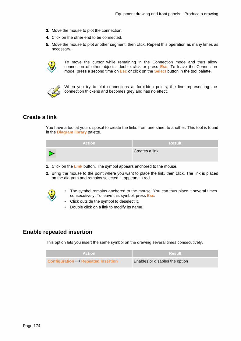
3. Move the mouse to plot the connection.
4. Click on the other end to be connected.
5. Move the mouse to plot another segment, then click. Repeat this operation as many times asnecessary.
To move the cursor while remaining in the Connection mode and thus allowconnection of other objects, double click or press Esc. To leave the Connectionmode, press a second time on Esc or click on the Select button in the tool palette.
When you try to plot connections at forbidden points, the line representing theconnection thickens and becomes grey and has no effect.
Create a link
You have a tool at your disposal to create the links from one sheet to another. This tool is foundin the Diagram library palette.
Action Result
Creates a link
1. Click on the Link button. The symbol appears anchored to the mouse.
2. Bring the mouse to the point where you want to place the link, then click. The link is placedon the diagram and remains selected, it appears in red.
• The symbol remains anchored to the mouse. You can thus place it several timesconsecutively. To leave this symbol, press Esc.
• Click outside the symbol to deselect it.• Double click on a link to modify its name.
Enable repeated insertion
This option lets you insert the same symbol on the drawing several times consecutively.
Action Result
Configuration Repeated insertion Enables or disables the option
Equipment drawing and front panels - Produce a drawing
Page 174

Choose symbol line thickness
You can choose between two line thicknesses for electrical symbols.
You cannot modify the line thickness of a symbol once you have drawn it.
Action Result
Configuration Symbol Fine line The next symbols you place on the drawingwill be drawn in fine lines.
Configuration Symbol Bold line The next symbols you place on the drawingwill be drawn in bold lines.
Equipment drawing and front panels - Produce a drawing
SISpro building 2.1 Page 175
Use standard diagrams
A standard diagram is a part of a drawing that you save for future re-use, in the same project orin other projects.
Create or modify a standard diagram
To create a standard diagram or modify an existing standard diagram, you must first select thepart of the drawing that must make up this standard diagram.
To select several graphs (p.278)
Action Result
Edit Create / Modify standard diagram Opening of the window Create a standarddiagram
1. Enter the name of the new standard diagram or click on the name of the standard diagramthat you want to modify (in this case, the drawing of this standard diagram will appear in theright-hand part of the window).
2. If necessary enter the description of the standard diagram.
3. Click on Save.
Retrieve a standard diagram
Action Result
Edit Insert standard diagram Opening of the window Insert a standarddiagram
1. Select the file containing the standard diagram that you want to insert. The drawing of thisstandard diagram will appear in the right-hand part of the window.
2. Click on Open. The window will close and the chosen standard diagram will appearanchored to the mouse.
3. Bring the mouse to the point where you want to place the standard diagram, then click.
4. Click outside the standard diagram to deselect it.
Equipment drawing and front panels - Produce a drawing
Page 176

Print drawings
A sheet model is automatically printed with the drawing. Before printing, remember to choosethe sheet model title block (p.178) and todefine the information appearing in the title block (p.179).
Action Result
File Print diagram
or or Crtl+P
Prints the drawing displayed
File Print preview
or
Checks formatting prior to printing
File Print configuration Chooses the printer and the printing options
Equipment drawing and front panels - Print drawings
SISpro building 2.1 Page 177

Choose the workspace and the sheet model title block
Presentation
You can choose the size of the pages that you wish to use as well as the page format and thetype of title block that will be printed with the drawings. The workspace can contain up to fourA0, i.e.t 64 A4 pages or 32 A3 pages.
You can modify the sheet models using the tool Customisation of sheet models(p.?).
Choose the workspace and the sheet model title block
Action Result
Configuration Workspace Opens the window Size workspace
1. In the Sheet model format frame, choose the page format (from A0 to A4) and the requiredpage orientation: Horizontal or Vertical.
The list below presents the title blocks available for the selected page format.
2. In the list of title blocks, click on the model that you wish to use.
3. In the Number of sheets frame, choose the number of pages you wish to have in thedirection of Height and Width. You can use up to four A0, i.e. 64 A4 pages or 32 A3 pages.
The Default button lets you save the chosen workspace to use it in your futuredrawings.
Equipment drawing and front panels - Print drawings
Page 178

Sheet model title block information
A variety of information can be printed in the sheet model title block such as the drawing nameand description as well as some information defined in the project general information and in theequipment properties.
You can modify the sheet models using the tool Customisation of sheet models(p.?).
Information Where Comment
Name of drawing File Rename a diagram
For more details, see Managedrawings (p.166)Description of drawing
Number of project Project general information,Project tab
Equipment Generalinformation
Used to directly access projectgeneral information to check itand complete it if required. Formore details, see Enter projectinformation (p.14).
Name of project
Description ofworksite
Name of customer Project general information,Customer tab
IP of equipment Equipment properties See Create equipment (p.22)
Isc of equipment
Type of equipment(enclosure range)
Free rows ofequipment
Calculated automatically oninstallation in enclosure
Equipment drawing and front panels - Print drawings
SISpro building 2.1 Page 179

Export the drawing
Presentation
You can export the drawing to other drawing software. Two methods are proposed:
• You can export the drawing to an AutoCAD® compatible file (DXF format).• You can transfer the drawing to another Windows software by copy/paste. In this case, you
can select the part of the drawing to be copied. To do this, you have two commands. Onecopies the electrical symbols like inseparable objects, while the other converts the electricalsymbols into graphic objects that can be broken down into various sub parts.
Export the drawing to an AutoCAD® file
Action Result
File Export DXF Opening of the Windows standard savewindow
Copy the drawing to another Windows software
Action Result
Edit Copy drawing Copies the selected part of the drawing intothe Windows clipboard (electrical symbols areconverted into graphic objects that can bebroken down into various sub parts)
Edit Copy Copies the selected part of the drawing intothe Windows clipboard (electrical symbols arecopied as inseparable objects)
To select several objects (p.278)
Equipment drawing and front panels - Export the drawing
Page 180

Produce marking labels
Presentation ......................................................................................................................... .182.Label creation window .......................................................................................................... .183.Design the marking labels .................................................................................................... .185.Printing labels ....................................................................................................................... .190.
Produce marking labels - Export the drawing
SISpro building 2.1 Page 181

Presentation
You can quickly create marking labels for your enclosures using preformated formattingtemplates. You can then print them on Schneider Electric precut-out cardboard sheets
For each item of equipment, you can create up to 10 label sheets in A4 format.
Action Result
in the tool bar or in the action bar of the
Design step
or Tools Label editor for enclosure
Opens the label design window (anequipment item must be selected in theBuilding General View)
Produce marking labels - Presentation
Page 182

Label creation window
1. Title bar (p.9)2. Menu bar (p.184)3. Tool bar (p.184)4. Label editing space (p.184)5. Text editor (p.184)6. Images palette (p.184)7. Decor palette (p.184)8. Status bar (p.184)
You can:• mask the tool bar and the status bar (menu Display Tool bar and Status bar)• move and resize palettes (p.279)
Produce marking labels - Label creation window
SISpro building 2.1 Page 183

Menu bar
The menu bar presents, in drop-down menus, the commands necessary to use the software.Some commands are also available:
• by a combination of keyboard keys (indicated to the right of the command in the menu),• by a button in the tool bar.
Tool bar
The tool bar offers quick access to the most commonly used commands. In the tool bar, eachcommand is represented by a button. A help bubble is associated with each button and appearswhen you leave the mouse on this button for a few seconds.
Label editing space
You compose the labels in this space. To help you produce them, several tools are at yourdisposal:
• three palettes allowing you to create texts and drawings,• formatting guides (frames, vertical markers and lines) and a grid that helps to align texts and
illustrations,• automatic numbering of labels.
Text editor
The text editor lets you create labels quickly. It proposes a list of predefined texts that can beplaced as they are or modified. You can also enter other texts.
Images palette
The Images palette is used to illustrate labels quickly by means of pictograms supplied with thesoftware.
Decor palette
The Decor palette is used to create your own drawings. It groups tools used to drawgeometrical shapes and to handle graphs.
Status bar
The status bar indicates from left to right:
• the description of the command selected in the menu bar or in the tool bar,• indication of keyboard locking in the CAPS mode (CAP) and activation of the numerical
keypad (NUM),• when you work in the drawing space, the coordinates of the mouse tip position,• the number of the label sheet displayed (1 to 10),• the type of labels being edited.
Produce marking labels - Label creation window
Page 184

Design the marking labels
Presentation
The marking labels can be illustrated in several ways:
• A text editor (5 (p.183)) proposes a list of predefined texts that can be placed as they are ormodified. You can also enter other texts.
• You can quickly illustrate labels using the pictograms supplied with the software. Thesepictograms are grouped in the Images (6 (p.183)) palette.
• You can place personal images on labels, for example your logo (in .BMP or .WMF format).
• You can create geometrical shapes using the tools in the Decor (7 (p.183)) palette.
You can create up to 10 label sheets for an equipment item. Formatting guides help you aligntexts and illustrations on the label sheets and the sheet strips can be renumbered.
Position drawings (p.185)
Place text on labels (p.185)
Place a pictogram on the label sheet (p.186)
Place a personal image on the label sheet (p.186)
Draw geometrical shapes (p.186)
Change page (p.186)
Renumber labels (p.187)
Position drawings
Various formatting guides are available to help you align texts and illustrations on the labelsheets. For more details, see Label positioning guides (p.188).
Place text on labels
Action Result
Display Text editor Displays or masks the text editor
1. In the text editor:
• Click on a text in one of the two lists. It will appear in the edit field under the lists. Ifnecessary, you can modify the text in this edit field.
• Or directly enter a text in the edit field.
2. Choose the text alignment: Left, Right or Centred.
3. Click on Insert.
Produce marking labels - Design the marking labels
SISpro building 2.1 Page 185

You can also double click on a text to select it.
4. Bring the mouse onto the label sheet to the point where you want to place the text, thenclick.
5. Click outside the text to deselect it.
Place a pictogram on the label sheet
Action Result
Display Images Displays or masks the Images pallet
1. In the Images pallet, click on a pictogram.
2. Bring the mouse onto the label sheet to the point where you want to place the pictogram,then click.
3. Click outside the pictogram to deselect it.
Place a personal image on the label sheet
Action Result
File Import BMP
File Import WMF
Inserts an image in the BMP or WMF format
1. In the File menu, choose Import BMP or Import WMF. The file selection standard dialoguewill appear.
2. Select the image file that you want to use, then click on Open.
3. Bring the mouse to the label sheet to the point where you want to place the image, thenclick.
4. Click outside the image to deselect it.
If you copy your personal image files in the .WMF format in the SisDe/WMF folder,these images will appear in the Images palette (after rebooting the software).
Draw geometrical shapes
You can complete label illustration by means of tools from the Decor palette. These tools letyou create geometrical shapes such as circles, rectangles, lines, polygons, etc. These shapesmay be coloured, resized or re-arranged. For the detail of the operations, see Use of drawingtools (p.272).
Produce marking labels - Design the marking labels
Page 186

Change page
You can create up to 10 label sheets (pages) for each item of equipment. The sheet numberdisplayed is given in the status bar (8 (p.183)).
Action Result
Display Next page Displays the next label sheet.
Display Previous page Displays the previous label sheet.
Renumber labels
A sheet contains several label strips. In each strip, labels are numbered from 1 to n. You canchange the starting number of each sheet strip.
Action Result
Changing line numbers Renumbers a label strip
Display Numbers Displays or masks label numbers
To renumber a label strip:
1. Click on the button Change line numbers.
2. Click on the label strip that you want to renumber. A dialogue box will appear.
3. In the field As from, enter the new starting number, then click on OK.
Produce marking labels - Design the marking labels
SISpro building 2.1 Page 187

Label positioning guides
Presentation
1. Label line frame2. Module3. Module vertical marker4. Text line5. Points grid
Several formatting guides are available to help you align texts and illustrations on the labelsheets.
The grid
The grid helps you align texts and drawings. When enabled, you can only position objectsaccording to predefined points whose spacing corresponds to grid pitch. Two grid pitches areavailable:
• a 5mm pitch,• a points grid, using the anchoring points of each module.
According to drawing space size and the zoom used, the grid may not be visible,even if it is enabled.
Action Result
Configuration Grid None The grid is cancelled
Configuration Grid Fine The 5mm grid is enabled
Configuration Grid Points The points grid is enabled
Produce marking labels - Design the marking labels
Page 188

Frames, vertical markers and lines
Frames, vertical markers and lines are guides that you can view to help you place texts andillustrations on the label sheets.
Frames, vertical markers and lines can be printed. If you do not want to print them,you must mask them before starting to print.
Action Result
Display Frame Displays or masks label line frames
Display vertical markers Displays or masks module vertical markers
Display Lines Displays or masks text positioning lines
The zoom
The zoom lets you enlarge part of the drawing space in order to distinguish details more clearly.
Action Result
Zoom Enlarges part of the drawing
Previous space The drawing is displayed with the previousenlargement
Full page The drawing space is redisplayed in full
To enlarge part of the drawing:
1. Click on Zoom. The cursor will assume the form of a magnifying glass.
2. Click on the drawing and, while holding down the mouse button, drag the mouse to delimitthe rectangle to be enlarged.
Produce marking labels - Design the marking labels
SISpro building 2.1 Page 189

Printing labels
Action Result
File Print
Crtl+P
Prints labels
Configuration Printer margin offset Indicates an offset to be applied in the topleft-hand corner of the page during printing
File Print preview Checks formatting prior to printing
File Print configuration Chooses the printer and the printing options
If you do not want to see the frames, vertical markers and lines on the printeddocument, you must mask them before starting to print. See Label positioning guides(p.188).
Produce marking labels - Printing labels
Page 190

Single line diagram step
Generate single-line diagrams ............................................................................................. .192.
SISpro building 2.1 Page 191

Generate single-line diagrams
Overview
You can automatically generate single-line diagrams for the various equipments of the project.These diagrams are built using SEE Building LT® pour SISpro building, tool for designing andrealising electrical diagrams from IGE+XAO.
You can choose the equipments for which the single-line diagram will be generated. Diagramsare generated using equipment cabling (p.48) data and cable characteristics entered in theSingle line diagram step window.
The generated single-line diagrams contain main technical information for incoming andoutgoing cables, functional names and descriptions, and cabling information.
Action Result
Single line diagram step Displays the window of the Single linediagram step
Single line diagram step - Generate single-line diagrams
Page 192

Cable step window
In this window, you visualise the electrical relations for one equipment of the project and youcan enter the characteristics for each outgoing cables of this equipment.
1. List of project equipments, allowing you to select the equipment to take into account forsingle-line diagram generation
2. Electrical relations for one equipment, such as defined in the Cabling (p.48) window3. Area for entering cable characteristics
• Column width can be modified.For more details, see Organisation of the SISpro building window (p.251)
• You can mask a column by clicking its title with the right button of the mouse. Todisplay all columns, click in the data entry area of the table with the right button ofthe mouse.
Single line diagram step - Generate single-line diagrams
SISpro building 2.1 Page 193

Generate single-line diagrams
1. In equipment list, select the equipment for which you want to generate the single-linediagram.
2. Click on one of the selected equipment. The electrical relations for this equipment aredisplayed.
3. Enter the characteristics for the equipment outgoing cables. You can specify the cable type,conductor type, cable composition, its section and length. In case of a multicore cable,Neutral and PE data entry areas are not accessible, the conductor for these polarities beingtaken into account in the multicore cable.
4. Repeat steps 2 and 3 for each selected equipment.
• End characteristic entry by pressing the Enter key, pressing the space bar orclicking on a cell.
• You can move into the table using keyboard arrow keys.• You can copy the same value into several cells in one operation:
1. Copy a value using Copy function from the contextual menu or usingCrtl+C keys.
2. Select the cells into which you want to copy the value using Shift or Ctrlkeys (see Selecting lines (p.278)).
3. Paste the value using Paste function from the contextual menu or Crtl+Vkeys.
5. Once all characteristics have been entered, select Generate diagram in the File menu orclick the button in the toolbar. The SEE Building LT® window is displayed and the
single-line diagrams are automatically generated. For more details on this tool, refer to SEEBuilding LT® documentation.
Single line diagram step - Generate single-line diagrams
Page 194

Quotation step
Presentation ......................................................................................................................... .196.Quotation step window ......................................................................................................... .197.Create a quotation ................................................................................................................ .201.Modify products in a quotation ............................................................................................. .202.Modify labour in a quotation ................................................................................................. .204.Add services to a quotation .................................................................................................. .206.Calculate consumables ........................................................................................................ .207.VAT rate ............................................................................................................................... .208.Margins ..................................................................................................................................209.Product discounts ................................................................................................................. .210.Synchronisation of a quotation with design .......................................................................... .212.Return to the catalogue prices ............................................................................................. .213.Print quotations .................................................................................................................... .214.Export quotations ................................................................................................................. .215.Configuration of margins and services by default ................................................................ .216.Default parameter saving ..................................................................................................... .218.
SISpro building 2.1 Page 195

Presentation
In the Quotation step, you prepare the project quotation. You can create several quotations forcomparison purposes . These quotations may correspond to different technical solutions(different equipment content) or to different sales proposals (services, margins, discounts,forced prices). For more details, see Equipment variant (p.12) et Quotation variant (p.12).
Prices can be displayed in a currency other than that of the price list.For more details, see Change currency (p.249).
Action Result
Quotation step
or Display Quotation
Displays the window of the Quotation step
Quotation step - Presentation
Page 196

Quotation step window
1. Step title bar (p.197)2. List of quotations created for the project. Quotations are identified by 2 different icons:
Quotation synchronous with design step
Quotation out of synchronisation
For more details, see Synchronisation of a quotation with design (p.212).3. Display space of the quotation selected in the list (2). This space has three tabs:
Part numbers tab (p.198) (quotation detail)Margins tab (p.199)Summary tab (p.200)
4. Detailed quotation of equipment (Part numbers tab (p.198))5. Total quotation calculation (Part numbers tab (p.198))6. Summary pane (p.200)
• You can mask some parts of the window and modify distribution between thevarious window spaces. For data presented as a table, you can also modify tablecolumn width.For more details, see Organisation of the SISpro building window (p.251) andCustomise menus and tool bars (p.253).
• Prices can be displayed in a currency other than that of the price list.For more details, see Change currency (p.249).
Step title bar
The title bar gives the name of the step with, to the right, the date of the current price list.
Quotation step - Quotation step window
SISpro building 2.1 Page 197

Part numbers tab
The Part number tab presents the detail of the quotation. The information displayed dependson what is selected in the list of quotations (2):
• If it is an equipment item, the quotation for this item is presented.• If it is a quotation:
• The top part of the window (4) presents the detailed calculation of the equipmentconsidered in this quotation. A scroll bar to the right lets you scroll information vertically.
• The bottom part (5) presents the total calculation of the quotation.
You can click on the plus or minus sign to the left of a piece of information toextend or reduce its display.
The content of the Part number tab can be customised. You can choose the columns and linesto be displayed for the detail of the equipment and for the total part of the quotation. For moredetails, see Customise the quotation content (p.243).
The following information can be displayed.
Information appearing against a sky blue background is information that can bemodified in the quotations. Once modified, this information appears in blue to markthe difference with respect to the Design step.
Information displayed for equipment
• name and quantity requested (seer Equipment in several copies below)• description• characteristics• product list sorted by family with, for each product:
• the label• the catalogue part number• the designation• the quantity• the internal part number• the manufacturer• the unit price list price• the unit net price (price calculated by applying discounts on the price list price)• the discount• the customer unit price (price calculated by applying the margin to the unit net price)• the total price
• sub-total by product family• total price of products• total amount of consumables• total price of products and consumables• list of additional services with their total• total price of additional services• sub-total of workshop labour• sub-total of worksite labour• equipment totalisation line: quantity, total price (see Equipment in several copies below)
Quotation step - Quotation step window
Page 198

Information displayed for the quotation
• list of additional services with their total• total price of additional services• total of products and consumables• total of workshop labour• total of worksite labour• total of equipment• total of services• total before tax• percentage and total VAT• Total inclusive of all taxes
Equipment in several copies
When an equipment item is requested in several copies at design level (in the properties for thisitem), in the quotations the item is described once only and the quotation calculation detail is fora single copy. The quantity is given next to the name of the equipment item at the top, and onthe equipment totalisation line, which also gives the unit price of the equipment and the totalprice calculated according to quantity.
Margins tab
The Margins tab presents the margins of the quotation selected in the list of quotations (2) andis used to modify them.
Information is divided into 3 tables:
• A first table in which you can define margins for products and consumables, for workshoplabour, for worksite labour and for services.
• A table presenting the equipment considered in the quotation. For each item is given thepurchase price before tax (Cost), the margin calculated and the selling price before tax.
• A table summarising this information for the entire quotation.
Quotation step - Quotation step window
SISpro building 2.1 Page 199

Summary tab
The Summary tab presents a summary of the quotation selected in the list of quotations (2):
• Information on the quotation: name and date of creation• Information on the project: information derived from project general information (Project
tab)• Information on the customer: information derived from project general information
(Customer tab)• Configuration: reminder of quotation calculation parameters• Services: list of additional services with their total• Costs and margins: summary of totals and margins on products, labour, services• Consumables: total for consumables• Price : total before tax, total VAT and total inclusive of all taxes of the quotation
Summary pane
Information space divided into three tabs:
Project Presents the summary of the calculation of one of the projectquotations. The header of the first column is a list in which you canselect the quotation to be displayed.
Equipment Presents the calculation of the equipment selected in the list ofquotations (2). The header of the first column is a list in which youcan select the quotation to be displayed. From one quotation toanother, the same equipment can have different calculationsaccording to the calculation parameters used in these quotations.
Properties Presents the characteristics of the equipment selected in the list ofquotations (2).
Quotation step - Quotation step window
Page 200

Create a quotation
A quotation is automatically created when a project is created, but you can create otherquotations. In each quotation you can choose the equipment to be considered, you can addproducts, modify prices, margins and discounts.
Each equipment item added to the project is automatically included in all thequotations and any modifications made in design on an equipment item areautomatically transferred to all the quotations that include this equipment item.
Action Result
Project Create a quotation
or
A new quotation appears in the list (2 (p.197))
› By default, all project equipment is included in the quotation that you have just created.Remove the tick from those that must not be considered.
Quotation step - Create a quotation
SISpro building 2.1 Page 201

Modify products in a quotation
Presentation
In the quotations, you can add or delete products, modify quantities and modify selling prices.These modifications are local to the quotation and to the equipment in which they are made andare not passed on to equipment at design level.
• When you modify products (modification of quantities, addition or suppression ofproducts) a warning message is displayed to inform you that the quotation is nomore synchronous with the design step. Out of synchronisation quotations areidentified with a specific icon (2 (p.197)). To cancel these modifications, refer toSynchronisation of a quotation with design (p.212).
• To cancel the modifications made on prices, refer to Return to the catalogueprices (p.213).
Modify prices and quantities
Only information displayed against a sky blue background can be modified (quantityand selling price of products). If you do not see the relevant columns, check thedisplay configuration (p.243).
To modify a quantity or a price in a quotation:
› In the tab Part numbers (3 (p.197)), click on the quantity or price (against a sky bluebackground) that you wish to modify and enter the new value.
You can modify the total price before tax of the quotation, but this total will no longercorrespond to the sum of prices detailed above.To recalculate the total price, refer to Return to the catalogue prices (p.213).
Add products
To add a product to a quotation, you can use most of the methods for adding products toequipment:
• Search for products in the Schneider Electric electronic catalogue• Direct search for Schneider Electric products• Search for products in the personal catalogue• Search for part numbers in the Schneider Electric and personal catalogues• Search for products in the favourites• Addition of non referenced products
For more details on these methods, refer to Choice of equipment products (p.25).
Quotation step - Modify products in a quotation
Page 202

• To add a product to equipment, first select this equipment in the list of quotations(2 (p.197)).
• To delete a product, set its quantity to 0.
Quotation step - Modify products in a quotation
SISpro building 2.1 Page 203

Modify labour in a quotation
Presentation
There are two types of labour: workshop labour and worksite labour.
Workshop labour corresponds to the time required to produce equipment. It is calculatedautomatically by the mounting wizards when installing devices in the switchboard. Thecalculation is based on the part number labour times recorded in the catalogues. The calculatedvalue can be modified.
In addition to workshop labour, you can enter additional labour time in the form of worksitelabour.
Workshop and worksite labour times are presented separately in the detailed calculation of eachitem of equipment (4 (p.197)) and in the total part of the quotation (5 (p.197)) where the hourlyrate of each labour type is also marked.
The hourly labour rates are defined in the quotation calculation parameters (see quotationcalculation parameters (see Configuration of margins and services by default (p.216)).
For each equipment item, you can modify the calculated workshop labour time and can enter aworksite labour time.
You can also modify the hourly rates for the entire quotation.
Modifications are local to the quotation and to the equipment in which they made.
Labour times can be expressed in hours and minutes or in hundredths of an hour.For more details, see Customise the quotation content (p.243).
Modify labour times
To modify the workshop labour time of an equipment item:
1. In the detailed equipment calculation, double click on the line for the workshop laboursub-total. The Workshop labour window appears.
2. In the Equipment frame, click on Enter then enter the new quantity of labour.
In the Quotation frame, you can modify the hourly cost of labour.
3. Click on OK.
To return to calculated workshop labour time:
1. In the detailed equipment calculation, double click on the line for the workshop laboursub-total. The Workshop labour window appears.
2. In the Equipment frame, click on calculated, then click on OK.
To enter the worksite labour time of an equipment item:
1. In the detailed equipment calculation, double click on the line for the worksite laboursub-total. The Worksite labour window appears.
Quotation step - Modify labour in a quotation
Page 204

2. In the Equipment frame, enter the quantity of labour.
In the Quotation frame, you can modify the hourly cost of labour.
3. Click on OK.
To modify the hourly cost of labour:
› In the quotation calculation total, click on the labour cost to be modified (workshop orworksite) and enter the new value.
Quotation step - Modify labour in a quotation
SISpro building 2.1 Page 205

Add services to a quotation
Presentation
In the quotations, you can add additional services to allow for auxiliary expenses such astransport or commissioning. These services can be added either at equipment level or globallyat quotation level.
The services total amount can be given either in the form of a fixed total or as a percentage ofthe total amount of products and consumables or the total amount of labour.
You can define services by default. These services will be automatically added toeach quotation when it is created.For more details, see Configuration of margins and services by default (p.216).
Add services
To add a service to an equipment item or a quotation:
1. With the right mouse button, click on the Service line in the detailed equipment calculation (4(p.197)) or in the quotation calculation total (5 (p.197)), then choose Create Service in thecontextual menu . The Service window appears.
2. Enter the service name.
3. In the Unit list, select the calculation method: quotation or percentage.
4. Enter the total amount or service calculation percentage.
5. If the service is a percentage, in the list Calculation on total, select the calculation basis:Labour or Products + Consumable.
6. Click on OK.
If you want this service to be added systematically to all your future quotations, tickthe box Add to services by default.
To modify a service:
1. Double click on the line of the service to modify. The Service window appears.
2. Make the modifications, then click on OK.
To delete a service:
› Click on the line of the service to be deleted with the mouse right button, then choose DeleteService in the contextual menu.
Quotation step - Add services to a quotation
Page 206

Calculate consumables
In the quotations, you can add for each equipment item a total amount for consumables. Thisamount can be expressed either as a fixed amount or as a percentage of the total price of theequipment products.
To add consumables to an equipment item:
1. Double click on the Consumable line in the equipment detailed calculation (4 (p.197)). Asmall window appears.
2. In the Unit list, select the calculation basis: currency of percentage.
3. Enter the total amount or the calculation percentage.
4. Click on OK.
To delete the total amount of consumables, set the value to 0.
Quotation step - Calculate consumables
SISpro building 2.1 Page 207

VAT rate
The VAT rate that you normally use is defined in the quotation calculation parameters, but youcan modify it locally in a quotation.
For more details, see Configuration of margins and services by default (p.216).
To modify the VAT rate in a quotation:
› In the quotation calculation total (5 (p.197)), click on the VAT rate, then enter the new value.
If the VAT rate is not visible, click on the sign on the line VAT total.
Quotation step - VAT rate
Page 208

Margins
Margins can be defined separately for products and consumables, workshop labour, worksitelabour and additional services.
The margins that you normally use are defined in the quotation calculation parameters, but youcan modify them locally in a quotation.
For more details, see Configuration of margins and services by default (p.216).
To modify the margins in a quotation:
1. Click on the tab Margins (3 (p.197)).
2. In the list of quotations (2), click on the quotation for which you want to define the margins.
3. In the first table at the top, enter the margins. You can enter either the margin percentage onselling price (column % on selling price) or the margin rate on purchase price (columnMultiplying coeff / Cost).
Quotation step - Margins
SISpro building 2.1 Page 209

Product discounts
Presentation
Discounts can be specified by product family or by part number. Discounts are valid only for theproject in which they are specified, but are common to all the project quotations.
Discounts by family can be saved to ensure their availability in your future projects.
Discounts can be calculated as a percentage or as a selling rate.For more details, see Customise the quotation content (p.243).
Discounts by product family
For each product family, you can indicate a basic discount and a complementary discount. Theeffective discount is the multiplication of the basic discount by the complementary discount.
Example
• For a product family, you normally have a 30% discount.• For a specific project, you obtain an additional discount of 10%.• The effective discount for this project will be 100%-(0.7*0.9)= 37%.
Action Result
Project Project discounts Opens the window Project discounts
1. In the Manufacturer list, select a manufacturer.
2. Above the table, tick the boxes corresponding to the discounts that you want to consider:Basic discounts (or Sales rates) and/or Complementary discounts (or Selling rates).
3. Click on a discount (or selling rate) and enter its value.
You can click on the button Apply to all to apply this value to all the productfamilies.
4. Repeat for the products of the other manufacturers.
• If you want to obtain the discounts that you have just defined in your futureprojects, click on the button By default.
• The Import button is used to retrieve discounts saved in a file (CSV format). Youcan also save current project discounts in a file (CSV format) using the Exportbutton.
Discounts by part number
You can enter specific discounts for the various part numbers of a project. These discounts arevalid only for the current project.
Quotation step - Product discounts
Page 210

Action Result
Project Project discounts Opens the window Project discounts
1. Click on the Part number tab. This tab presents the list of project part numbers. Thediscounts (or selling rates) displayed initially correspond to the discounts (or selling rates)defined in the Family tab.
2. Click on a discount (or selling rate) and enter its new value.
• You can click on the button Apply to all to apply this value to all the other partnumbers.
• You can return to the discount defined for the product family by clicking on theRe-initialise button.
Quotation step - Product discounts
SISpro building 2.1 Page 211

Synchronisation of a quotation with design
Modifications made to products in a quotation (addition or suppression of products, modificationof quantities) remain local to this quotation and are not passed on to equipment at design level.Synchronisation of the quotation with design cancels the modifications made to the quotation. Itre-initialises quantities and deletes the products added.
To synchronise a quotation with design
› In the list of quotations (2 (p.197)), click on the quotation to be synchronised with the rightmouse button, then choose Synchronise in the contextual menu.
Quotation step - Synchronisation of a quotation with design
Page 212

Return to the catalogue prices
The modifications made to product prices in a quotation remain local to this quotation. They arenot passed on to equipment at design level. You can cancel these modifications globally or partnumber by part number. You also can recalculate the total amount of the quotation.
To return to the catalogue price for a part number:
1. In the list of quotations (2 (p.197)), click on the relevant quotation.
2. In the Part numbers tab, click with the mouse right button on the price to be modified, thenchoose Return to the catalogue price in the contextual menu.
To return to the catalogue prices for all the quotation part numbers:
1. In the list of quotations (2 (p.197)), click on the relevant quotation.
2. In the Part numbers tab, click with the mouse right button on one of the prices displayedagainst a sky blue background, then choose Return to the catalogue prices in thecontextual menu.
To recalculate the total amount of a quotation
When you modify the total amount before tax of a quotation, this total will no longer correspondto the sum of prices detailed above. To recalculate the total corresponding to the product prices:
1. In the list of quotations (2 (p.197)), click on the relevant quotation.
2. In the Part numbers tab, click with the mouse right button, then choose Amountcalculation in the contextual menu.
Quotation step - Return to the catalogue prices
SISpro building 2.1 Page 213

Print quotations
Presentation
You can print separately the quotation calculation and the summary of the various projectquotations.
You can configure the information to be printed. For more details, see Customise thequotation content (p.243).
Print a quotation
1. In the list of quotations (2 (p.197)), click on the quotation to be printed.
2. In the File menu, choose Print. The Print window appears.
3. Tick the documents to be printed: Quotation and/or Summary and click on OK.
4. The standard Print window appears. Choose the print options and click on OK.
Quotation step - Print quotations
Page 214

Export quotations
Presentation
You can export quotations to use them subsequently in other software (word processors,spreadsheets). Four export formats are available:
• The format CSV (*.csv) is a text format in which information is separated by the character (;).This format is accepted by a large number of spreadsheets including Microsoft Excel. In thisformat the quotation calculation is exported, but not the summary.
• The format RTF (*.rtf) is a format accepted by most word processors. In this format, thequotation calculation and/or the summary can be exported. The documents produced areformatted, ready to be printed. They are accompanied by a document in the CSV formatcontaining the project general information that you can use in a mass mailing system.
• The format Text (*.txt) is a text format in which information is separated by tabulations. Inthis format, the quotation calculation is exported, but not the summary.
• The format XML (*.xml) is a structured text format using the XML syntax.
You can configure the information to be exported.For more details, see Customise the quotation content (p.243).
Export a quotation
1. In the list of quotations (2 (p.197)), click on the quotation to be exported.
2. In the File menu, choose Export Quotation. The standard selection window appears.
3. In the Type list, choose the export format.
4. If necessary modify the position and name of the file, then click on Save.
If you have chosen the RTF format, the Export RTF window appears. Tick thedocuments to be exported: Quotation and/or Summary, then click on OK.
Quotation step - Export quotations
SISpro building 2.1 Page 215

Configuration of margins and services by default
You can define the calculation parameters that you normally use:
• the margins to be applied to products and consumables, to workshop labour, worksite labourand services,
• the labour rates for work performed in the workshop and on the worksite,• the VAT rate for products and labour,• additional services (consumables, transport, commissioning, etc.).
Action Result
Configuration Services and margins Opens the window Configuration of marginsand services by default (p.217)
Quotation step - Configuration of margins and services by default
Page 216

Description of the default services and margins configurationwindow
Services
Cost of workshop labour Used to enter the labour cost for work performed in theworkshop.
Cost of worksite labour Used to enter the labour cost for work performed on theworksite.
VAT rate Used to enter the VAT rate to be applied to products andlabour.
Default services on projects- Default services onequipment
These grids are used to add services that will be automaticallyadded when a quotation is created, either for each equipmentitem or at global quotation level.
Each line corresponds to a service. The total amount ofservices can be indicated either in the form of a fixed amount,or as a percentage of the total amount of products andconsumables or the total amount of labour.
To add a service:
1. Click on the Create button. A new line appears at thebottom of the grid.
2. Enter the name of the service in the Service column.
3. In the Unit column, select the calculation method: currencyor percentage.
4. In the Value before tax column, enter the total amount orthe calculation percentage of the service.
5. If the service is a percentage, in the list Calculation ontotal, select the calculation base: Labour or Products +Consumable.
To delete a service:
› Click on the service to be deleted, then click on Delete.
Margins
This tab lets you define the margins to be applied to products and consumables, to workshoplabour, worksite labour and to additional services.
You can enter either the margin percentage on selling price (column % on selling price) orthe margin rate on purchase price (column Multiplying coeff / Cost).
Quotation step - Configuration of margins and services by default
SISpro building 2.1 Page 217

Default parameter saving
You can save in just one operation all the parameters defined for the current quotation. Theywill thus be automatically retrieved in the future quotes that you create.
Action Result
The parameters of the current quote aresaved.
Quotation step - Default parameter saving
Page 218

Order form step
Presentation ......................................................................................................................... .220.Order form step window ....................................................................................................... .221.Create an order form ............................................................................................................ .224.Modify a product in an order form ........................................................................................ .225.Synchronisation of an order form ......................................................................................... .226.Print order forms ....................................................................................................................227.Export order forms .................................................................................................................228.Manage suppliers ................................................................................................................. .229.
SISpro building 2.1 Page 219

Presentation
In the Order form step, you create the order forms intended for your suppliers.
You can create an order form from a quotation. The equipment included in the quotation is thenautomatically selected in the order form and the modifications made to the products at quotationlevel are passed on to the order form.
In the order forms you can add products and modify quantities.
Prices can be displayed in a currency other than that of the price list.For more details, see Change currency (p.249).
Action Result
Step Order form
or Display Order form
Displays the window of the Order form step
Order form step - Presentation
Page 220

Order form step window
1. Step title bar (p.221)2. List of order forms created for the project. Order forms are identified by 2 different icons:
Synchronous order form
Out of synchronisation order form
For more details, see Synchronisation of an order form (p.226).3. Display space of the order form selected in the list (2). This space contains two tabs:
Part numbers (p.221) (Quotation calculation detail)Adaptation form (p.223)
4. Properties (p.223)
• You can mask some parts of the window and modify distribution between thevarious window spaces. For data presented in table form, you can also modifytable column width.For more details, see Organisation of the SISpro building window (p.251) andCustomise menus and tool bars (p.253).
• Prices can be displayed in a currency other than that of the price list.For more details, see Change currency (p.249).
Step title bar
The title bar gives the name of the step with, to the right, the date of the current price list.
Part numbers
The Part number tab presents the detail of an order form. The information displayed dependson what is selected in the list of order forms (2):
Order form step - Order form step window
SISpro building 2.1 Page 221

• If it is an equipment item, the calculation for this item is presented.• If it is an order form, the window presents the detailed calculation of the equipment
considered in this order form, followed by total calculation of the order form.
You can click on the plus or minus sign to the left of a piece of information toextend or reduce its display.
The content of the Part number tab can be customised. You can choose the columns and linesto be displayed for detail of the equipment and for the total part of the order form. For moredetails, see Customise order form content (p.246).
The following information can be displayed.
Information appearing against a sky blue background is information that can bemodified in the order forms. Once modified, this information appears in blue to markthe difference with respect to the Design step.
Information displayed for equipment:
• name• manufacturer• product list sorted by manufacturer and by family with, for each product:
• the label• the catalogue part number• the designation• the quantity• the unit price list price (excl. discount)• the discount granted• the unit net price (with discount)• the total price before tax• the internal part number• the manufacturer
• sub-total by product family• sub-total for the manufacturer• total before tax and quantity (see Equipment in several copies below)• total VAT• total price of equipment
Information displayed for the order form:
• total price before tax of products• total (and rate) of VAT• total price inclusive of all taxes
Equipment in several copies
When an equipment item is requested in several copies at design level (in the properties of thisitem), in the order forms the item is described once only and the calculation detail correspondsto a single copy. The quantity is marked next to the equipment name at the top, and on the linefor the total before tax, which also gives the unit price of the equipment and the total pricecalculated according to quantity.
Order form step - Order form step window
Page 222

Adaptation form
The Adaptation form tab presents the adaptation forms generated for devices with mountingoptions. They give the mounting instructions that the supplier will require. Devices with mountingoptions have a part number beginning with NOTA.
Properties
This information space depends on what is selected in the list of order forms (2). It presents:
• Either the properties of the equipment item.• Or the properties of the order form:
• a space to enter a description• a list to select the quotation to which the order form must be attached• a list to select the supplier• tick boxes to select the manufacturers to consider in the order form
Order form step - Order form step window
SISpro building 2.1 Page 223

Create an order form
You must create an order form for each project product supplier. The supplier is the productdistributor and the person to whom the order form is addressed.
A supplier can propose products from one or more manufacturers. When an order form iscreated, you choose the supplier. The order form can only contain the products ofmanufacturers attached to the chosen supplier.
Order forms are created from equipment content defined at Design step or from a referencequotation. In this case, only equipment included in the quotation is considered in the order formand modifications made to products at quotation level are passed on to the order form.
Once created, an order form is not automatically updated when modifications are made atdesign level or in the reference quotation. To consider these modifications, you mustsynchronise (p.226) the order form.
You can create partial order forms that do not allow for all the equipment of a quotation.
Before creating order forms, you must define the suppliers (p.229).
Action Result
Project Create an order form
or
Opens the window Create an order
1. Enter the name of the order form.
2. You can create the order form from the design step or from a reference quotation:
• To create the order form from the design step, in the Initial quotation list, select None.• To create the order form from a reference quotation, in the Initial quotation list, select
the quotation for which you want to order the products. The equipment included in thequotation will be automatically selected in the order form and the modifications made toproducts at quotation level will be passed on to the order form.
3. In the Supplier list, select the product supplier. The corresponding manufacturers will beautomatically selected in the order form.
4. Click on OK.
The order form appears in the list (2 (p.221)) and the equipment considered in the order formare selected.
The order form characteristics are displayed in the properties (4) pane: reference quotation,supplier and manufacturers taken into account.
• You can deselect equipment. The order form will then be partial.• You can also change the initial quotation, the supplier and deselect
manufacturers.
Order form step - Create an order form
Page 224

Modify a product in an order form
Presentation
In order forms, you can add or delete products and modify quantities. These modifications arelocal to the order form and to the equipment in which they are made and are not passed on toequipment at design level or in the quotations. You can thus add to an order form products thatare not part of the project.
When you modify products (modification of quantities, addition or suppression of products) awarning message is displayed to inform you that the order form is no more synchronous with thedesign step or with its reference quotation, if it has been created from a quotation. Out ofsynchronisation order forms are identified with a specific icon (2 (p.221)).
To cancel the modifications, refer to Synchronisation of an order form (p.226).
Modify quantities
Only information displayed against a sky blue background can be modified (quantity).If you do not see the relevant columns, check the display configuration (p.246).
To modify a quantity in an order form:
› In the tab Part number (3 (p.221)), click on the quantity (against a sky blue background) thatyou want to modify and enter the new value.
Add products
To add a product to an order form, you can use most of the methods for adding products toequipment:
• Search for products in the Schneider Electric electronic catalogue• Direct search for Schneider Electric products• Search for products in the personal catalogue• Search for part numbers in the Schneider Electric and personal catalogues• Search for products in the favourites• Addition of non referenced products
For more details on these methods, refer to Choice of equipment products (p.25).
• To add a product to an equipment item, first select this item in the list of orderforms 2 (p.221)).
• To delete a product, set its quantity to 0.
Order form step - Modify a product in an order form
SISpro building 2.1 Page 225

Synchronisation of an order form
Modifications made to products in an order form (addition or suppression of products,modification of quantities) remain local to this order form. Moreover, modifications made atdesign step level and in quotations are not automatically passed on to order forms.
Synchronisation of an order form cancels the modifications made to the order form and updatethe order form with the modifications made in the design (if the order form has been createdfrom the design) or in the quotation (if the order form has been created from a quotation). Itre-initialises quantities and deletes the products added.
To synchronise an order form
› In the list of order forms (2 (p.221)), click on the order form to be synchronised with the rightmouse button, then choose Synchronise in the contextual menu.
Order form step - Synchronisation of an order form
Page 226

Print order forms
You can print the various project order forms and their adaptation form.
You can configure the information to be printed. For more details, see Customiseorder form content (p.246).
To print an order form:
1. In the list of order forms (2 (p.221)), click on the order form to be printed.
2. In the File menu, choose Print. The Print window appears.
3. Tick the documents to be printed: Order form and/or Adaptation form, then click on OK.
4. The standard Print window appears. Choose the print options and click on OK.
According to the documents that you have requested, the Print window mayappear several times:• once for the order form• once for the adaptation form
You can choose each time different print options or click on Cancel to canceldocument printing.
Order form step - Print order forms
SISpro building 2.1 Page 227

Export order forms
You can export order forms to use them at a later stage in other software (word processors,spreadsheets). Four export formats are available:
• The format CSV (*.csv) is a text format in which information is separated by the character (;).This format is accepted by a large number of spreadsheets including Microsoft Excel. In thisformat, the order form is exported but not the adaptation form.
• The format RTF (*.rtf) is a format accepted by most word processors. In this format, theorder form and/or the adaptation form can be exported. The documents produced areformatted, ready to be printed. They are accompanied by a document in CSV formatcontaining the project general information that you can use in a mass mailing system.
• The format Text (*.txt) is a text format in which information is separated by tabulations. Inthis format, the order form is exported, but not the adaptation form.
• The format XML (*.xml) is a structured text format using the XML syntax.
You can configure the information to be exported.For more details, see Customise order form content (p.246).
To export an order form:
1. In the list of order forms (2 (p.221)), click on the order form to be exported.
2. In the File menu, choose Export order form. The standard file selection window appears.
3. In the Type list, choose the export format.
4. If necessary modify the position and name of the file, and click on Save.
If you have chosen the RTF format, the Export RTF window appears. Tick thedocuments to be exported: Order form and/or Adaptation form, then click onOK.
Order form step - Export order forms
Page 228

Manage suppliers
The supplier is the product distributor. He is the person to whom the order form is addressed.
A supplier can propose the products from one or more manufacturers. When an order form iscreated, you choose the supplier. The order form can only contain the products ofmanufacturers attached to the chosen supplier.
To create order forms, you must thus define suppliers.
Action Result
Project Project suppliers Opens the window Project suppliers
To add a supplier:
1. Click on the Create button. A new line appears in the List of suppliers.
2. In the grid placed beneath, enter the information for the new supplier.
3. Allocate manufacturers to this supplier, moving them from the list Available manufacturersto the list Allocated manufacturers.
4. Click on OK.
If you want to use this supplier in your future projects, click on the Default buttonbefore clicking on OK.
Order form step - Manage suppliers
SISpro building 2.1 Page 229

Page 230

Using data
Presentation ......................................................................................................................... .232.Compile the project file ......................................................................................................... .233.Export project data ............................................................................................................... .236.
SISpro building 2.1 Page 231

Presentation
You can compile a file containing the elements generated during the various project completionsteps. These data can also be exported in various formats for use with other software such asspreadsheets and word processors.
Compile the project file (p.233)
Export project data (p.236)
Using data - Presentation
Page 232

Compile the project file
Presentation
You can compile a file containing the elements generated during the various project completionsteps. To compile this file you can print the following documents:
• the equipment product lists• cabling information• electrical single-line diagrams• the switchboard front panel drawings• the switchboard mounting documents• the freely created drawings and diagrams• the identification labels• the equipment quotation calculation• the quotation calculation summary• the order forms for the various product suppliers• the adaptation forms
Product lists
Product lists can be printed from the Design step. You can print separately the product list ofeach project equipment item.
Information is printed such as presented on the screen. The product list display and thus theprint content can be customised. For more details, see Customise the design step product list(p.241).
Action Result
File Print
or or Ctrl+P
Prints the product list of the equipmentselected in the Building General View (2(p.19)) of the Design step window
File Print configuration Chooses the printer and the print options
Cabling information
Equipment cabling information can be printed from the Wiring view tab in the Design stepwindow.
To print equipement cabling information :
1. In the Design step window, click on Wiring view tab (3 (p.19)).
2. In the Building General View (2 (p.19)) click on the equipment for which you want to printcabling information.
3. In the Wiring view tab, click on the button in the toolbar (1 (p.48)).
Using data - Compile the project file
SISpro building 2.1 Page 233

Single-line diagrams
You can automatically generate a single-line diagram for each equipment of the project. Thesediagrams may be printed from the tool used to generate the diagrams. For more details, seeGenerate single-line diagrams (p.192).
Action Result
Single line diagram step Displays the window of the Single linediagram step
To print the generated diagrams:
› From SEE Building LT® File menu, select Print.
Front panel drawings
Front panel drawings are created when products are installed in the switchboard. They can onlybe printed for equipment whose products have been mounted using an installation in theswitchboard wizard, and must be printed using this wizard.
To print the equipment front panel drawing:
1. In the Building General View (2 (p.19)) of the Design step window, double click on theequipment whose front panel drawing you want to print. The installation in the switchboardwindow appears.
2. Display the Switchboard design tab.
3. In the File menu, choose Print.
For more details, refer to Print the Prisma Plus switchboard (p.110) (Prisma Plus), or Print theswitchboard (p.153) (Modular enclosure).
Mounting documents
Mounting documents are compiled when products are installed in the switchboard. They canonly be printed for equipment whose products have been mounted using an installation in theswitchboard wizard, and must be printed using this wizard.
To print the equipment mounting document:
1. In the Building General View (2 (p.19)) of the Design step window, double click on theequipment whose mounting document you want to print. The installation in the switchboardwindow appears.
2. Display the Mounting document tab.
3. In the File menu, choose Print.
For more details, refer to Print the Prisma Plus switchboard (p.110) (Prisma Plus), or Print theswitchboard (p.153) (Modular enclosure).
Free drawings and diagrams
In the Design step, a set of drawing tools lets you rework switchboard front panels and build
Using data - Compile the project file
Page 234

single-line diagrams freely.
To print freely created drawings:
1. In the Tools menu, choose Drawing. The drawing design window appears.
2. In the File menu, choose Print diagram.
For more details, refer to Print drawings (p.177).
Identification labels
In the Design step, a set of tools lets you create identification labels for your modularenclosures.
To print the identification labels:
1. In the Building General View (2 (p.19)) of the Design step window, click on the equipmentwhose identification labels you want to print.
2. In the Tools menu, choose Label editor for modular enclosures. The label design windowappears.
3. In the File menu, choose Print.
For more details, refer to Printing labels (p.190).
Calculate equipment quotation and the quotation summary
Several quotations can be created in a project. A quotation contains two separate documents,the actual quotation calculation part and a technical and sales summary. These documents canbe printed separately from each other.
Quotations can be printed from the Quotation step. To print the quotation calculation and thesummary of one of the project quotations:
1. In the list of quotations (2 (p.197)) of the Quotation step window, click on the quotation to beprinted.
2. In the File menu, choose Print.
For more details, refer to Print quotations (p.214).
Order forms and adaptation forms
A project can contain several order forms, at least one for each product supplier. An order formcontains two separate documents, the actual order form part and the adaptation form. Thesedocuments can be printed separately from each other.
Order forms can be printed from the Order form step. To print an order form and its adaptationform:
1. In the list of order forms (2 (p.221)) of the Order form step window, click on the order form tobe printed.
2. In the File menu, choose Print.
For more details, refer to Print order forms (p.227).
Using data - Compile the project file
SISpro building 2.1 Page 235

Export project data
Presentation
The elements generated during the various project completion steps can be exported for usewith other software such as spreadsheets and word processors. A variety of formats and exportmethods are available. You can export the following documents:
• the equipment product lists• device cabling• electrical single-line diagrams• switchboard front panel drawings• switchboard mounting documents• freely created drawings and diagrams• quotations• order forms
Product lists
Product lists can be exported from the Design step. You can export separately the product listof each project equipment item. Four export formats are available:
• The format Text (*.TXT) is a text format in which information is separated by tabulations. Inthis format, the product list is exported such as presented in the tab Products (3 (p.19)) ofthe Design step window.
• The format Excel (*.CSV) is a text format in which information is separated by the character(;). This format is accepted by a large number of spreadsheets including Microsoft Excel. Inthis format, the product list is exported such as presented in the Products tab of the Designstep window.
• The format XML (*.XML) is a structured text format using the XML syntax.
The product list display and thus the export content may be customised. For more details, seeCustomise the design step product list (p.241).
Action Result
File Export products choice of format
or CSV export
or XML export
Exports the product list for the equipmentselected in the Building General View (2(p.19)) of the Design step window
Device cabling
Device cabling information can be exported from the Design step. Data are exported to a file inXML format. This file contains, for each project equipment item, the electrical hierarchy of thedevices as well as all the information for each device making up the equipment.
Using data - Export project data
Page 236

Action Result
File Export Cabling
or
Opens the Windows standard save window
Single-line diagrams
You can automatically generate a single-line electric diagram for each equipment of the project.These diagrams may be exported from the tool used to generate the diagrams. For moredetails, see Generate single-line diagrams (p.192).
Action Result
Single line diagram step Displays the Cable definition window
To export the generated diagrams:
› From SEE Building LT® File menu, select Save as.
Front panel drawings
Front panel drawings are created when products are installed in the switchboard. They can onlybe exported for equipment whose products have been mounted using an installation in theswitchboard wizard, and they must be exported using this wizard.
To export the equipment front panel drawing
› In the Building General View (2 (p.19)) of the Design step window, double click on theequipment whose front panel drawing you want to export. The installation in the switchboardwizard window appears.
Several export methods and formats are available. For more details refer to Export the PrismaPlus switchboard front face (p.113) (Prisma Plus), or Export the switchboard front face (p.156)(Modular enclosure).
Mounting documents
Mounting documents are compiled when products are installed in the switchboard. They canonly be exported for equipment whose products have been mounted using an installation in theswitchboard wizard, and they must be exported using this wizard.
To export the equipment mounting document:
› In the Building General View (2 (p.19)) of the Design step window, double click on theequipment whose mounting document you want to export. The installation in the switchboardwizard window appears.
Several methods are available. For more details refer to Export the Prisma Plus switchboardmounting document (p.116) (Prisma Plus), or Export the mounting document (p.159) (Modularenclosure).
Using data - Export project data
SISpro building 2.1 Page 237

Free drawings and diagrams
In the Design step, a set of drawing tools lets you rework the switchboard front panels and buildsingle-line diagrams freely.
To export the freely created drawings:
› In the Tools menu choose Drawing. The drawing design window appears.
Several methods are available. For more details, refer to Export the drawing (p.180).
Quotation
Several quotations can be created in a project. A quotation contains two separate documents,the actual calculation part and a technical and sales summary. These documents can beexported from the Quotation step.
To export a quotation:
1. In the list of quotations (2 (p.197)) of the window of the Quotation step, click on thequotation to be exported.
2. In the File menu, choose Export quotation.
Several export formats are available. For more details, refer to Export quotations (p.215).
Order forms
A project can contain several order forms, at least one for each product supplier. An order formcontains two separate documents, the actual order form part and the adaptation form. Thesedocuments can be exported from the Order form step.
To export an order form:
1. In the list of order forms (2 (p.221)) of the window of the Order form step, click on the orderform to be printed.
2. In the File menu, choose Export order form.
Several export formats are available. For more details, refer to Export order forms (p.228).
Using data - Export project data
Page 238

Customising thesoftware
Presentation ......................................................................................................................... .240.Customise the design step product list ..................................................................................241.Customise the quotation content .......................................................................................... .243.Customise order form content .............................................................................................. .246.Change currency .................................................................................................................. .249.Choose SISpro building default files .................................................................................... .250.Organisation of the SISpro building window ..........................................................................251.Customise menus and tool bars ........................................................................................... .253.
SISpro building 2.1 Page 239

Presentation
Various options are at your disposal to adapt software behaviour to your working preferencesand habits:
• Customise the design step product list (p.241)
• Customise the quotation content (p.243)
• Customise order form content (p.246)
• Change currency (p.249)
• Choose SISpro building default files (p.250)
• Organisation of the SISpro building window (p.251)
• Customise menus and tool bars (p.253)
Customising the software - Presentation
Page 240

Customise the design step product list
You can customise the presentation of information in the Products tab of the Design step (3(p.19)). The presentation chosen for the display is also used for printing and for exporting theproduct list.
You can choose:
• the number of detail lines to be displayed for a product and its accessories,• the columns to be displayed, their display order and the title label.
Action Result
Configuration Design Opens the window Display / Print / Export(p.?)
Customising the software - Customise the design step product list
SISpro building 2.1 Page 241

Description of the Display/Print/Export window
Number of lines per device Used to choose the number of detail lines to be displayed fora product and its accessories
• All lines: for each product, all the references will bedisplayed.
• Number of lines: for each product, only the number oflines indicated will be displayed.
Configure columns This frame is used to choose the columns to be displayed andtheir display order. The list Represented columns presentsthe columns displayed in the display order, while the listAvailable columns presents the columns that may bedisplayed.
Action Result
Moves the selected column from the listAvailable columns to the listRepresented columns
Moves the selected column from the listRepresented columns to the listAvailable columns
Moves all the columns from the listAvailable columns to the listRepresented columns
Moves all the columns from the listRepresented columns to the listAvailable columns
Moves the selected column to the top orthe bottom of the list
AddFunctionalNames toprintingandexport
When this option is ticked, the functionalnames are printed or exported with theproducts
Customising the software - Customise the design step product list
Page 242

Customise the quotation content
You can choose:
• the information to be displayed in the References tab of the window of the Quotation step(3 (p.197)),
• the labour time display mode: hundredths of an hour or hours and minutes,• the discount calculation mode (percentage or selling rate),• the information to be considered when exporting quotations,• the information to be considered when printing quotations,• columns order.
Action Result
Configuration Quotation (you must be inthe Quotation step)
Opens the window Quotation configuration(p.?)
Customising the software - Customise the quotation content
SISpro building 2.1 Page 243

Description of the quotation configuration window
Display
This tab lets you customise the information display in theReferences tab of the Quotation step window.
Columns This frame lets you choose the columns to be displayed.
1. Move the columns from the list Available columns to thelist Represented columns using the button.
2. Organise columns position using and buttons.
Parameters This frame lets you:
• display labour in hundredths of an hour or in hours/minutes• manage discounts as a percentage or as a selling rate (0
to 1)
Equipment lines This frame lets you choose the information to be displayed foreach equipment item:
• the equipment name• the equipment label• the equipment characteristics• the sub-total by product family• the sub-total for the products• the sub-total for workshop labour• the sub-total for worksite labour• the sub-total of services• the sub-total of equipment• the product references• the price of each reference
Quotation lines This frame lets you choose the information to be displayed foreach quotation:
• the total price for products• the total price for workshop labour• the total price for worksite labour• the total price for services• the total price for equipment• the total price before tax• VAT and the VAT rate• the total price inclusive of all taxes
Customising the software - Customise the quotation content
Page 244

Export
This tab lets you define the information to be considered whenexporting quotations.
Columns This frame lets you choose the columns to be displayed.
1. Move the columns from the list Available columns to thelist Represented columns using the button.
2. Organise columns position using and buttons.
Equipment lines This frame lets you choose the information to be displayed foreach equipment item:
• the equipment name• the equipment label• the equipment characteristics• the sub-total by product family• the sub-total for products• the sub-total for workshop labour• the sub-total for worksite labour• the sub-total for services• the sub-total for equipment• the product references• the price of each reference
Quotation lines This frame lets you choose the information to be exported foreach quotation:
• the total price for equipment• the total price for workshop labour• the total price for worksite labour• the total price for services• the total price for equipment• the total price before tax• VAT and VAT rate• the total price inclusive of all taxes
Profiles This frame is used to save parameters in various profiles inorder to re-use them according to needs.
Printing
This tab is used to define the information to be considered when printing quotations. For moredetails, see the tab Export (p.245).
Customising the software - Customise the quotation content
SISpro building 2.1 Page 245

Customise order form content
You can choose:
• the information to be displayed in the References tab of the window of the step Order form(2 (p.221)),
• the discount calculation mode (percentage or selling rate),• the information to be considered when exporting order forms,• columns order.
Action Result
Configuration Order form
(You must be in the Order form step).
Opens the window Configure an order form(p.247)
Customising the software - Customise order form content
Page 246

Description of the Configure an order form window
Display
This tab is used to customise the information display in theReferences tab of the Order form step window.
Columns This frame lets you choose the columns to be displayed.
1. Move the columns from the list Available columns to thelist Represented columns using the button.
2. Organise columns position using and buttons.
Parameters This frame is used to manage discounts as a percentage oras a selling rate (0 to 1).
Equipment lines This frame lets you choose the information to be displayed foreach equipment item:
• the equipment name• the equipment description• the product family• the total price by manufacturer• the price of each reference• the sub-total before tax• the total VAT• the sub-total inclusive of all taxes
Order form lines This frame lets you choose the information to be displayed foreach order form:
• the total price before tax• VAT and VAT rate• the total price inclusive of all taxes
Customising the software - Customise order form content
SISpro building 2.1 Page 247

Export
This tab is used to define the information to be consideredwhen exporting order forms.
Columns This frame lets you choose the columns to be displayed.
1. Move the columns from the list Available columns to thelist Represented columns using the button.
2. Organise columns position using and buttons.
Equipment lines This frame lets you choose the information to be exported foreach equipment item:
• the equipment name• the equipment label• the product family• the total price by manufacturer• the price of each reference• the sub-total before tax• the total VAT• the sub-total inclusive of all taxes
Order form lines This frame lets you choose the information to be exported foreach order form:
• the total price before tax• VAT and VAT rate• the total price inclusive of all taxes
Profiles This frame is used to save parameters in various profiles inorder to re-use them according to needs.
Printing
This tab is used to define the information to be considered when printing order forms. Formore details, see the tab Export (p.248).
Customising the software - Customise order form content
Page 248

Change currency
In a project, prices may be displayed in a currency other than that of the current price list. Justenter the currency to be used and the exchange rate and all project prices will be automaticallyconverted into the new currency.
Action Result
Configuration Currency Opens the window Currency
You can enter the description of the new currency and its exchange rate or select thecurrency in the list: the relevant exchange rate is then automatically displayed.
See also:
Update the price list (p.258)
Customising the software - Change currency
SISpro building 2.1 Page 249

Choose SISpro building default files
The data generated by SISpro building are saved in various files. You can choose these files.
Action Result
Configuration Default files Opens the window Default files
1. Click on the file to be modified, then click on the Modify button. The standard file selectionwindow appears.
2. Select the relevant file and click on OK.
Customising the software - Choose SISpro building default files
Page 250

Organisation of the SISpro building window
Presentation
You have a variety of options to organise the software window according to your preferences.You can:
• mask the tool bars and the status bar,• modify the height and width of some parts of the window,• modify table column width.
Moreover, the menu bar and the tool bars can be customised (p.253).
Display or mask part of the window
Action Result
Display Status bar Displays or masks the status bar (7 (p.9))
Display Tool bar Tool bar name
or contextual menu Tool bar name
Displays or masks the tool bar or the displayspace selected
List of tool bars:
Standard Main tool bar (3 (p.9))
Steps Step bar (4 (p.9))
Title Step title bar (6 (p.9))
Properties Order form information space (4 (p.221))
Summary Design step information space (8 (p.19)) and Quotation (6(p.197))
Configurators (small) Installation in the switchboard wizard tool bar (3 (p.9))
Configurators (large) Design step action bar for installation in the switchboard (4(p.19))
Modules (small) Tool bar for design of drawings and labels (3 (p.9))
Modules (large) Design step action bar for design of drawings and labels (4(p.19))
Modify distribution between two parts of the window
1. Place the mouse on the line separating the two parts. The cursor takes the form of an arrowwith two tips or .
2. Click and hold down the mouse button.
3. Move the mouse. The separating line follows the mouse movements.
4. Release the mouse button when the separating line is in the required position.
Customising the software - Organisation of the SISpro building window
SISpro building 2.1 Page 251

Adjust table column width
To modify table column width:
1. Place the mouse in the table title on the separation between two columns. The cursor takesthe form of an arrow with two tips .
2. Click and hold down the mouse button.
3. Move the mouse. The column separating line follows the mouse movements.
4. Release the mouse button when the columns have the required width.
To adjust column width to its content:
1. Place the mouse in the table title on the separation between the column to be modified andthe next column. The cursor takes the form of an arrow with two tips .
2. Double click on the separating line.
Customising the software - Organisation of the SISpro building window
Page 252

Customise menus and tool bars
Presentation
The menu bar and the tool bars can be customised. You can add or delete commands, moveand resize tool bars, modify display options and keyboard shortcuts.
Some display spaces (Summary, Properties, action bars) can be moved andresized like tool bars, but you cannot modify their content.
Move a tool bar
Tool bars can be anchored (fixed to one of the edges of the window) or floating. If you drag afloating tool bar to the window edge, it turns into an anchored tool bar.
› To move an anchored tool bar, click on the displacement bar (dotted line to the left or the topof the bar) or on its title, then drag it to the required place.
› To move a floating tool bar, click on its title then drag it to the required place.
Resize a tool bar
Floating tool bars can be resized.
1. Place the mouse on one of the edges of the tool bar. The cursor takes the form of an arrowwith two tips .
2. Click and hold down the mouse button.
3. Move the mouse. The tool bar is deformed as it follows the mouse movements.
4. Release the mouse button when the tool bar has reached the required size.
Modify the tool bars and menus
Action Result
Display Tool bar P=Customise
or contextual menu Customise
Opens the window Customise (p.254)
In the Customise window, you can:
• add or delete commands from the menu bar, tool bars and contextual menus,• modify the keyboard shortcuts,• choose tool bar display options.
Customising the software - Customise menus and tool bars
SISpro building 2.1 Page 253

Description of the Customise window
Commands
To add a command to a tool bar:
1. Click on a category, then on a command.
2. Drag the command to the tool bar.
To delete a command, drag it outside the tool bar.
Tool bar
Tool bar List of existing tool bars.
Re-initialise Re-initialises the tool bar selected such as it was afterinstalling the software (only affects predefined tool bars).
Re-initialise all Re-initialises all the predefined tool bars such as they wereafter installing the software.
Display legends Tick this box to display legends under the buttons of the toolbar selected to the left.
Customising the software - Customise menus and tool bars
Page 254

Keyboard
This tab is used to create or modify keyboard shortcuts.
To allocate a combination of keys to a command:
1. Select the category, then the command. If a shortcut is allocated to this command, thecombination of keys is indicated in the frame Current keys.
2. Click in the field Press the new shortcut key.
3. Press the combination of keys that you want to allocate to the command.
If the combination of keys is already allocated, the name of the associatedcommand is given below and the Allocate button is not available.
4. Click on Allocate.
To delete a shortcut:
1. Select the category, then the command.
2. In the Current keys frame, click on the shortcut to be deleted.
3. Click on Delete.
The Re-initialise all button lets you cancel all the modifications made to the shortcuts.
Menu
In this tab, you can choose the animation to be used when opening the menus, activategreying of drop-down menus and modify contextual menus.
To modify a contextual menu:
1. In the list Choose the contextual menu, select the menu that you want to modify. Themenu is displayed.
2. In the tab Commands, click on a category, then on a command.
3. Drag the command up to the contextual menu.
To delete a command, drag it outside the contextual menu.
The Re-initialise all button lets you cancel all the modifications made to the contextual menuselected in the list Choose the contextual menu.
Options
This tab lets you modify the appearance of the tool bars: display of help bubbles, shortcuts,small and large icons.
Customising the software - Customise menus and tool bars
SISpro building 2.1 Page 255

Page 256

Additional functions
Update the price list ...............................................................................................................258.Import/export the personal catalogue ................................................................................... .259.Update internal part numbers ............................................................................................... .261.Customise default values of Schneider Electric catalogues ................................................. .263.Customise sheet models ...................................................................................................... .264.
SISpro building 2.1 Page 257

Update the price list
You can update product prices in the catalogues using an updating file.
The date of the price list of the last update is displayed in the title bar of the windowof the Design (1 (p.19)) step. This is the date marked in the updating file and not theupdating date. If you want to keep a track of the date at which updating wasperformed, enter this in the Description field of the Update price list window.
Action Result
Tools Update price list Opens the window Update price list
1. In the New update frame, enter the name of the update file. You can look for this file usingthe button .
2. Click on OK.
You can enter a description for updating (it will appear in the Last update frame thenext time you open the Update price list window) and modify the device description.
Additional functions - Update the price list
Page 258

Import/export the personal catalogue
You can import and export the content of the personal catalogue in the form of standard ASCIIfiles.
Action Result
Tools Import/Export the personalcatalogue
Opens the window Import/Export catalogue
1. Click on Export to export data or on Import to import data.
2. In the window brought up, select the file containing the data to be imported or enter thename of the file in which you want to export the data. You can define the structure of theimport or export file. Click on Import format or Export format. The window File format (p.260)will appear.
• In import and export formats, not all fields are compulsory. Enter 0 in the Positionand Length columns of those you do not want to use.
• In standard format, the last field must be followed by a separator.
Additional functions - Import/export the personal catalogue
SISpro building 2.1 Page 259
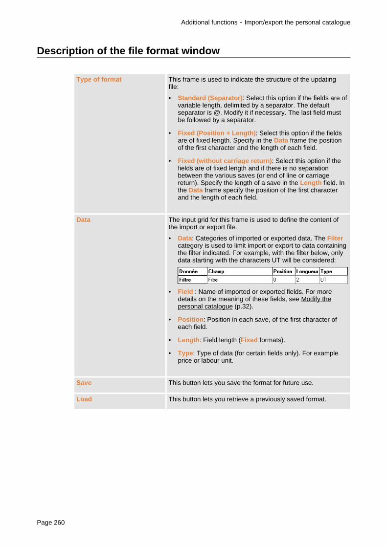
Description of the file format window
Type of format This frame is used to indicate the structure of the updatingfile:
• Standard (Separator): Select this option if the fields are ofvariable length, delimited by a separator. The defaultseparator is @. Modify it if necessary. The last field mustbe followed by a separator.
• Fixed (Position + Length): Select this option if the fieldsare of fixed length. Specify in the Data frame the positionof the first character and the length of each field.
• Fixed (without carriage return): Select this option if thefields are of fixed length and if there is no separationbetween the various saves (or end of line or carriagereturn). Specify the length of a save in the Length field. Inthe Data frame specify the position of the first characterand the length of each field.
Data The input grid for this frame is used to define the content ofthe import or export file.
• Data: Categories of imported or exported data. The Filtercategory is used to limit import or export to data containingthe filter indicated. For example, with the filter below, onlydata starting with the characters UT will be considered:
• Field : Name of imported or exported fields. For moredetails on the meaning of these fields, see Modify thepersonal catalogue (p.32).
• Position: Position in each save, of the first character ofeach field.
• Length: Field length (Fixed formats).
• Type: Type of data (for certain fields only). For exampleprice or labour unit.
Save This button lets you save the format for future use.
Load This button lets you retrieve a previously saved format.
Additional functions - Import/export the personal catalogue
Page 260

Update internal part numbers
You can import and export the internal part numbers of your catalogues in the form of standardASCII files.
Action Result
Tools Update internal part numbers Opens the window Loading internal partnumbers
1. In the list of manufacturers, select the manufacturer(s) to be updated.
2. Click on Load part numbers to import part numbers or on Export part numbers to exportpart numbers.
3. In the window brought up, select the file containing the data to be imported, or enter thename of the file in which you want to export the data.
When you import part numbers, if the part number update file is not in standard format, youhave two options:
• If the format has already been saved, click on Existing to retrieve it.
• Or click on New to define an update format. The window New format (p.262) will appear.
• In import and export formats, not all fields are compulsory. Enter 0 in the Positionand Length columns of those that you do not want to use.
• In standard format, the last field must be followed by a separator.
Additional functions - Update internal part numbers
SISpro building 2.1 Page 261

Description of the New format window
Type of format This frame indicates the structure of the update file:
• Separator: Select this option if the fields are of variablelength, delimited by a separator. The default separator is@. Modify it if necessary. The last field must be followedby a separator.
• Fixed: Select this option if the fields are of fixed length. Inthe Compulsory parameters frame specify the position ofthe first character and the length of each field.
Filter (Manufacturer code) This frame indicates the manufacturers to be updated. Onlythe manufacturers present in this list will be considered in theupdate.
The buttons Add, Delete and Modify are used to modify thelist. Each filter is made up of a description and a code of 3characters maximum that will act as a filter.
Compulsory parameters This frame is used to define the Position of the first characterof each field and, for a Fixed format, the Number ofcharacters of each item of information.
Standard This button is used to re-initialise the default format.
Load This button is used to retrieve a previously saved format.
Save This button is used to save the format for future use.
Additional functions - Update internal part numbers
Page 262

Customise default values of Schneider Electric catalogues
When you choose products in Schneider Electric catalogues, a window will appear to let youdefine the product characteristics (see Description of the product characteristics window (p.29)).In this window, some characteristics and options are preselected, but you can modify thesepreselections.
Action Result
Tools Modifying default values Opens the window Choose a product
Just select the products and their characteristics. The selected characteristics are saved asdefault values but no products are added to the project.
For more details on product selection, see Direct search for Schneider Electric products (p.30).
Additional functions - Customise default values of Schneider Electric catalogues
SISpro building 2.1 Page 263

Customise sheet models
Presentation
A certain number of sheet models are delivered with the software. The sheet modelcustomisation tool lets you customise them.
Action Result
Tools Sheet model customisation Displays the sheet model customisation toolwindow.
Sheet model editor window
1. Title bar (p.9)2. Menu bar (p.265)3. Tool bar (p.265)4. Space in which you modify the sheet models5. Decor palette (p.265)
Additional functions - Customise sheet models
Page 264

6. Status bar (p.265)
You can:• mask the tool bar, the status bar and the Decor palette (menu Display Tool
bar, Status bar and Decor palette)• move and resize palettes (p.279)
Menu bar
The menu bar presents, in drop-down menus, the commands necessary to use the software.Some commands are also available:
• by a combination of keys on the keyboard (indicated to the right of the command in themenu),
• by a button in the tool bar.
Tool bar
The tool bar offers quick access to the most commonly used commands. In the tool bar, eachcommand is represented by a button. A help bubble is associated with each button and appearswhen you leave the mouse on this button for a few seconds.
Decor palette
The Decor palette groups the tools used to draw geometrical shapes and to handle graphs.
Status bar
The status bar indicates from left to right:
• the description of the command selected in the menu bar or the tool bar,• indication of keyboard locking in CAPS mode (CAP) and activation of the numerical keypad
(NUM),• when you work in the drawing space, the coordinates of the mouse tip position.
Modify sheet models
A certain number of sheet models are delivered with the software. Some of these sheet modelscan be customised. Sheet models cannot be modified and you cannot create other sheetmodels than those delivered. You can save modifications only in the sheet models whosedescription ends with a number placed between brackets.
Modifying sheet models
For more details, see Modify a sheet model (p.267).
Adding attributes
Attributes let you print updating information automatically, such as general project information orthe sheet number. For more details, see Add attributes to the sheet model (p.268).
Geometrical shape drawing
A graphic tool palette lets you draw geometrical shapes such as circles, rectangles, lines,polygons, etc. These shapes can be coloured, re-sized and re-arranged. For the detail of theoperations, see Use of drawing tools (p.272).
Additional functions - Customise sheet models
SISpro building 2.1 Page 265

Graphs can be copied, moved and deleted using the standard commands (mouse, Del key,Copy/Paster, Cut/Paste, Delete commands of the Edit menu.
Assistance with positioning drawings
You have a zoom to enlarge the drawing and a grid to help you align graphs. For more details,see Assistance with positioning on a sheet model (p.269).
Additional functions - Customise sheet models
Page 266

Modify a sheet model
Action Results
File Save
or or Crtl+S
Saves the modifications.
Not available for template sheet models.
File Save as Saves the modifications.
File Open
or or Crtl+O
Opens a sheet model.
File Close Closes the current sheet model.
To modify a sheet model
1. Open the sheet model to be modified:
a. In the File menu, choose Open. The window Size the workspace will appear.
b. In the Sheet model format frame, choose the page format (from A0 to A4) and therequired page orientation: Horizontal or Vertical. The following list presents the titleblocks available for the selected page format.
c. In the list of title blocks, click on the model that you want to modify. You can only modifysheet models whose description ends with a number between brackets. If you open atemplate sheet model and modify it, you must save the modifications in one of themodifiable sheet models using the command Save as.
2. Make the modifications.
3. Save the modifications:
• If the sheet model is modifiable, use File Save.
• Else use File Save as. A window will appear. In the Sheet model list, select the sheetmodel in which the modifications must be saved. Only modifiable sheet models appear inthis list. In the Description field, enter the sheet model description.
Additional functions - Customise sheet models
SISpro building 2.1 Page 267

Add attributes to the sheet model
Presentation
Attributes let you print updating information automatically, such as general project information orthe sheet number.
You can modify the size of the attribute characters.
Available attributes are:
<Name> Project name entered in general information
<Number> Project number entered in general information
<Name of equipment> Equipment name
<Customer> Customer name entered in general information
<Diagram> Diagram name
<Description> Diagram description
IP: 125 Isc : 50 IP and Iscc entered in equipment properties
Type : Type of equipment entered in properties
Free rows : ZZ % Free rows of equipment calculated when placing in theenclosure
NUMFOL Sheet number
NBPGT Total number of pages
Add an attribute to the sheet model
Action Result
Adding an attribute Opening a window presenting the attributesnot yet placed on the sheet model
Choose attribute character size
Action Result
Configuration Attribute Used to choose attribute text size
Additional functions - Customise sheet models
Page 268

Assistance with positioning on a sheet model
You have a zoom to enlarge the drawing and a grid to help you align graphs.
The grid
The grid helps you align texts and drawings. When enabled, you can only position objectsaccording to predefined points whose spacing corresponds to grid pitch.
You can hide the grid. However, when a grid pitch is selected, it is active even if the grid is notvisible.
According to drawing space size and the zoom used, the grid may not be visible,even if it is enabled.
Action Result
Displays or masks the current grid
Options Grid None
or
The grid is cancelled
Options Grid Normal
or
The 10mm grid is enabled
Options Grid Fine
or
The 5mm grid is enabled
Options Grid Very fine
or
The 2.5mm grid is enabled
The zoom
The zoom is used to enlarge part of the drawing space so as to distinguish details more clearly.
Action Result
Display Zoom in
or
Enlarges part of the drawing
Display Zoom out
or
The drawing is displayed with the previousenlargement
Display 100%
or
The drawing space is redisplayed in full
Additional functions - Customise sheet models
SISpro building 2.1 Page 269

To enlarge part of the drawing:
1. Click on the Zoom button. The cursor will assume the shape of a magnifying glass.
2. Click on the drawing and, while holding down the mouse button, drag the mouse to delimitthe rectangle to be enlarged.
Additional functions - Customise sheet models
Page 270

Appendices
Select objects ....................................................................................................................... .278.Reminders on how to use windows ...................................................................................... .279.
SISpro building 2.1 Page 271

Use of drawing tools
A graphic tool palette (Decor palette) lets you draw geometrical shapes such as circles,rectangles, lines, polygons, etc. and add texts. These shapes and texts can be coloured,re-sized and re-arranged.
• Once selected, tools used to draw geometrical shapes remain active. To abort thetool being use, press Esc or click on another tool.
• To select several drawings (p.278)
Appendices -
Page 272

Select objects Selects drawings.
Rotation by 90° Rotates selected drawings by 90°.
Proportional resizing Resizes selected drawings by respecting their widthand height proportions.
Resizing Resizes selected drawings in height, width or inproportional manner.
Horizontal resizing Resizes selected drawings in width.
Vertical resizing Resizes selected drawings in height.
Creating an ellipse Details of operations (p.274)
Creating a circle Details of operations (p.274)
Creating an arc Details of operations (p.275)
Creating a rectangle Details of operations (p.275)
Creating a segment Details of operations (p.275)
Creating a broken line Details of operations (p.275)
Creating a polygon Details of operations (p.276)
Creating a text Enters a text and places it on the drawing space.
Modifying the text Modifies the selected text.
Placing in foreground Places selected drawings above the others.
Placing in background Places selected drawings beneath the others.
Group Groups several graphic objects into a single object inorder to handle them more easily.
Ungroup Separates grouped drawings.
Managing tracing paper Selects tracing paper.
Modifying tracing paper Moves selected drawings to another tracing paper.
Appendices -
SISpro building 2.1 Page 273

Creating horizontal dimensions
Creating vertical dimensions
Creating inclining dimensions
Sizes drawings horizontally, vertically or inclining.
Details of operations (p.276)
Configuration Drawing (orDecor attributes)
or
Modifies the line style, the colour and filling pattern ofthe figures plotted using the drawing tools. The Decorattributes button symbolises the selected formatting.
If you modify these attributes but no drawing isselected, the new formatting will be applied to all thefigures drawn from then on.
Configuration Text (or Textattributes)
or
Modifies text formatting (colour, style, inclination,alignment, size and front). The Text attributes buttonsymbolises the selected formatting.
If you modify these attributes but no text is selected, thenew formatting will be applied to all the texts enteredfrom then on.
Configuration Arrow (or Arrowattributes)
or
Creates line ends automatically. The type of endchosen is applied to all the lines you draw. The Arrowattributes button symbolises the selected formatting.
You cannot modify the style of a line once you havedrawn it.
Draw an ellipse
1. Click at the point where the ellipse is to begin and hold down the mouse button.
2. Diagonally drag the mouse pointer. The ellipse will develop.
3. Release the mouse button when the ellipse has reached the required size.
Draw a circle
1. Click on the position in the centre of the circle.
2. Move the mouse to develop the circle.
Appendices -
Page 274

3. Click when the circle has reached the required size.
Draw an arc
1. Click on the position of one of the ends of the arc.
2. Move the mouse, then click on the position of the other end of the arc.
3. Move the mouse to develop the circle arc.
4. Click when the circle arc has reached the required size.
Draw a rectangle
1. Click on the position of a vertex of the rectangle and hold down the mouse button.
2. Diagonally drag the mouse pointer. The rectangle will develop.
3. Release the mouse button when the rectangle has reached the required size.
Draw a segment
1. Click at one end of the segment.
2. Move the mouse to plot the segment.
3. Click when the segment has reached the required size.
Appendices -
SISpro building 2.1 Page 275

Draw a broken line
1. Click on the position of one of the ends of the first segment of the broken line.
2. Move the mouse to plot the segment.
3. Click when the first right-hand segment has reached the required size.
4. Move the mouse to plot the second segment of the broken line, then click. Repeat thisoperation as many times as necessary.
5. When the broken line is finished, double click on the last point.
While you draw, you can cancel the last segment plotted by pressing Esc.
Draw a polygon
1. Click on the position of the first vertex of the polygon.
2. Move the mouse then click on the position of the second vertex of the polygon. Repeat thisoperation as many times as necessary.
3. Double click on the last vertex.
While you draw, you can cancel the last segment plotted by pressing Esc.
Size drawings
1. Click on one of the ends of the segment to be sized. A small cross will appear at the pointwhere you have clicked.
2. Click on the other end of the segment to be sized. The sizing line will appear between twoanchoring lines.
3. Drag the mouse to bring the sizing line up to its final position, then click. The dimension is
Appendices -
Page 276

calculated and placed on the drawing.
Horizontal
sizing
Vertical
sizing
Oblique
sizing
Appendices -
SISpro building 2.1 Page 277

Select objects
Selecting lines
To select several adjacent lines:
1. Click on the first line to be selected.
2. Click on the last line to be selected holding down the CAPS key. All the lines found betweenthese two lines will be selected.
In some cases, you can also:
1. Click in the top left-hand corner of the zone to be selected and, while holding down themouse button, encircle all the objects to be selected in the selection rectangle developing.
2. Release the mouse button.
To select several dissociated lines:
› Click on each line to be selected holding down the Ctrl key.
If you click on a selected line while holding down the Ctrl key, you will deselect it.
Select / deselect graphic objects
The selected graphic objects are encircled by a red line which is normally dotted.
To select an empty figure (without filling colour) click on its edge.
To select an isolated object:
› Click on it.
To select several adjacent objects:
1. Click on the drawing field and, while holding down the mouse button, encircle all the objectsto be selected in the selection rectangle developing.
2. Release the mouse button.
To select several dissociated objects:
› Click on it while holding down the CAPS key.
To deselect all the selected objects:
› Click next to them.
To deselect objects one by one:
› Hold down the CAPS key and click on each object to be deselected.
Appendices - Select objects
Page 278

Reminders on how to use windows
Move and re-size a palette
Palettes can be moved anywhere on the screen:
› Click on the palette title then drag it up to the required position.
Palette shape and size can be modified. To resize a palette:
1. Place the mouse on one of its edges. The cursor assumes the shape of a two-tip arrow.
2. Click and hold down the mouse button.
3. Move the mouse. The palette is deformed according to mouse movements.
4. Release the mouse button when the palette reaches the required size.
Contextual menu
Menu obtained by clicking in the software window with the mouse secondary button (normallythe right button). The content of this menu depends on the object on which the mouse ispositioned when you click.
Appendices - Reminders on how to use windows
SISpro building 2.1 Page 279

Page 280

Glossary
Device
Entity defining an electrical device. A device and its accessories form a product.
Diagram marker or Functional name
Information attached to a product in order to identify it on the diagram.
Equipment
Lowest level of a project tree, able to receive products. Equipment has a specific functional role.
Functional unit
This standardised term groups:
• installation elements (mounting and front plates),
• connection elements (current distribution blocks, upstream connection devices, busbarconnection).
A functional unit is specific to a device and to its installation type (vertical or horizontal).
Functional zone
Entity designed to structure a project and in which equipment is grouped. A functional zonecannot contain products directly.
Manufacturer
The manufacturer corresponds to the producer or the product brand.
Personal catalogue
You can create your own database to save products not referenced in the catalogues deliveredwith the software. This database forms your own personal catalogue.
Products
This term stands for an assembly made up of a device and its accessories or of products in thewide sense of the term (non electrical).
SISpro building 2.1 Page 281

Sheet model
Frame and title block added to drawings on printing. There are several sheet models for eachsheet format (A3, A4, etc.)
Supplier
Product distributor for one or more manufacturers.
Page 282

Index
AAdaptation form, .221.Association (of enclosures), .94.
BBuilding General View, .19.Busbar
configuration, .122.Functional Unit / Busbar incompatibilities, .90.installation of horizontal busbars, .92.
CCabling, .48., .76., .136.Characteristics, .22., .71., .134.Configuration
choice of terminals, .74.installation in the switchboard, .118.mounting and connection , .73.
Connection on terminalssee Terminals
Consumable, .206.Copy (products), .25., .43.Currency, .249.Customisation
default value , .263.of software, .118., .123., .250., .251., .253.order form content, .246.product list , .241.quotation content, .243.sheet model, .264.
DDefault values, .263.Deletion (of products)
in a switchboard, .69., .135.in equipment, .25., .46.
Designmodular enclosure design , .131.presentation, .18.Prisma Plus switchboard design, .61.
SISpro building 2.1 Page 283

Devicecabling, .48.change orientation, .100., .145.install in Prisma Plus switchboard, .56., .61.install in modular enclosure, .126., .131.rotate, .100., .145.
Dimensioning (front panel drawing), .276.Discounts, .210.Document (mounting)
display, .57., .127.export, .106., .116., .151., .159.printing, .110., .153.
Duct (addition to an enclosure), .95.
EEconomic summary, .197., .214., .215.Electrical relations
see CablingEquipment
create, .22.secured equipment, .11.
Equipment drawing and front panel, .162.Export
cabling, .236.drawings, .180.front panels, .113., .156.mounting document, .106., .116., .151., .159.order form, .228.product list, .236.project file, .236.quotation, .215.references, .106., .115., .151., .158.
FFavourites
creation, .37.product choice favourites, .25., .36.
Filedefault archiving, .250.project, .233.
Free rowin a Prisma Plus switchboard , .71., .109., .112.in a modular enclosure, .143., .155.on sheet model, .268.
Functional labelallocation, .48.display, .130., .129., .60., .59.
Functional nameallocation, .48.display, .59., .60., .129., .130.
Functional unitdevice mounting, .81.
Functional zone (creation), .22.
GGrid (positioning aid)
drawing and front panel, .169.installation in switchboard, .105., .149.labels, .188.sheet model, .269.
Group
Page 284

electrical group, .48.motor starter group, .76.
H
IImport/export
see Personal catalogueIncoming unit, .70.Installation
horizontal busbars (Prisma Plus switchboard), .92.Human-Switchboard interface (Prisma Plus switchboard), .93.in Prisma Plus switchboard, .56.in Kaedra enclosure, .141.in modular enclosure, .126.sockets, .138., .141.
J
K
LLabels (identification), .182.Labour
calculate labour time workshop, .107., .152.modify labour times, .204.
Link component, .48., .172.
MMargins, .209.Menu (customisation), .253.Modification
favourites, .37.personal catalogue, .32.price, .202.products, .25., .100., .145., .202., .225., .263.quantities, .22., .225., .202.switchboard, .100., .145.
Modular enclosuredesign, .126., .131.product choice , .135.
Mountingmounting devices on functional unit, .61., .81.switchboard mounting direction, .121.
N
OOpening
project after updating the price list, .11.project prior to SISpro building 2.1, .11.
Optionsfor installation in the switchboard, .118.mounting and connection, .73.
Order formcreation, .224.export, .236.
SISpro building 2.1 Page 285

presentation, .7., .220., .221.print, .233.
PPACK enclosure, .91.Page (change), .104., .148.Part number
free, .42.internal, .261.
Personal cataloguechoose products, .25., .31.import/export, .259.modification, .32.
Placing in enclosure, .126., .56.Preconfigured assembly
choice, .25., .38., .69., .135.creation, .40.
Pricemodification, .202.recalculate quotation total amount, .213.return to catalogue prices, .213.update, .258.
Price listopening a project after updating the price list, .11.update, .258.
Printingcabling, .53., .233.drawings and front panels, .177., .233.labels, .190., .233.mounting document, .110., .153.order form, .227., .233.part numbers, .110., .153.product list , .233.project file, .233.quotation, .214., .233.table, .110., .153.
Products (choose), .25., .69., .135.Project
opening a project after updating the price list, .11.opening a project prior to SISpro building 2.1, .11.
Project information, .14.Properties
equipment, .22.project, .14.
QQuotation
creation, .201.presentation, .196.synchronisation with design, .212.
RReturn to catalogue prices, .213.Rotate (device), .100., .145.
SServices, .206.Sheet model
choice, .110., .153., .177.customisation, .264.
Page 286

Single-line diagramexport, .236.generate, .192.print, .233.
Summary, .19., .197.Supplier, .229.Switchboard (Prisma Plus)
add a duct , .95.architecture choice, .85.associate enclosures, .94.design, .56., .61.free design , .67.guided design, .63.product choice, .69.quick design, .65.
Switchboard architecture (choose), .85.Switchboard finish, .98.Synchronisation
of order form, .226.of quotation with design, .212.
TTerminals
calculate power terminals, .61., .71., .79.configuration, .79.connection on terminals, .48.
Time (labour)calculation, .107., .152.modification, .204.
Title blocksee Sheet model
Tool barcustomisation, .123., .251., .253.display, .9., .48., .57., .127., .163., .183., .264.
Tracing paper (enclosures, mounting plates, devices, front plates, doors), .100., .103., .147.Type (of equipment), .22.
UUnit (labour)
for installation in the switchboard, .107., .152.in the quotations, .243.
Update price list, .11., .258.
VVariant
equipment, .12.quotation , .12.
VAT, .208.View (of switchboard), .103., .147.
WWindow
cabling, .48.customisation, .123., .251., .253.Design step, .19.drawing, .163.identification labels, .183.installation in switchboard, .57., .127.main, .9.Order form step, .221.
SISpro building 2.1 Page 287

Project step, .14.Quotation step, .197.
X
Y
ZZoom
for customisation of sheet models, .269.for installation in the switchboard, .105., .149.for the drawing, .169.for the labels, .188.
Page 288