sistema radiante ribassato
TRANSCRIPT

Institüt fürGebäudenEnergetik
Lehrstuhl fürHeiz-undRaumlufttechnik
Universität Stuttgart
Test report for specific thermal outputof floor heating constructionin acc. to EN 1264
Type RIBASSATO, load distribution layer: 45 mm, pipe: 16 x 2 mm
test report no.: HB09 P282
Stuttgard, 26.05.2009
The report shall not be reproduced expect in full without the written approval of the testing lab.The test results relase only to the items tested
The test laboratoryis accredit in acc. to ISO/IEC 17025 by DAR.Acceptances from certification bodies:DINCERTOCO / RAL / AFNOR / BSI / AENOR
sistema radianteRIBASSATO
RISCALDAMENTO
COMISA spa3 • 35
SCHeda teCniCa 3•03
Rev
01 -
2015
1031
- Com
isa
ener
gy -
Saic
om -
Rese
term
iche
sis
tem
a RI
BASS
ATO
page of 9 test report no. HB09 P282
RISCALDAMENTO
CERTIFICAZIONI SISTEMA RADIANTERIBASSATO
Institüt für GebäudeEnergetikLehrstuhl für Heiz - und Raumlufttechnik
COMISA spa3 • 36
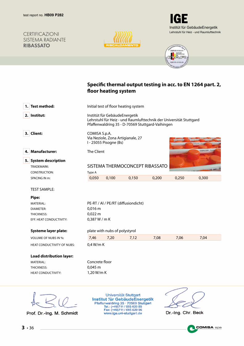
Specific thermal output testing in acc. to EN 1264 part. 2, floor heating system
1. Test method: Initial test of floor heating system
2. Institut: Institüt für GebäudeEnergetik Lehrstuhl für Heiz - und Raumlufttechnik der Universität Stuttgard Pfaffenwaldring 35 - D-70569 Stuttgard-Vaihingen
3. Client: COMISA S.p.A. Via Neziole, Zona Artigianale, 27 I - 25055 Pisogne (Bs)
4. Manufacturer: The Client
5. System description TRADEMARK: SISTEMA THERMOCONCEPT RIBASSATO CONSTRUCTION: Type A
SPACING IN m: 0,050 0,100 0,150 0,200 0,250 0,300 TEST SAMPLE:
Pipe: MATERIAL: PE-RT / Al / PE/RT (diffusiondicht) DIAMETER: 0,016 m THICKNESS: 0,022 m EFF. HEAT CONDUCTIVITy: 0,387 W / m K
Systeme layer plate: plate with nubs of polystyrol
VOLUME OF NUBS IN %: 7,46 7,20 7,12 7,08 7,06 7,04
HEAT CONDUCTIVITy OF NUBS: 0,4 W/m K Load distribution layer: MATERIAL: Concrete floor
THICKNESS: 0,045 m HEAT CONDUCTIVITy: 1,20 W/m K

page of 9
RISCALDAMENTO
CERTIFICAZIONI SISTEMA RADIANTERIBASSATO
test report no. HB09 P282
Institüt für GebäudeEnergetikLehrstuhl für Heiz - und Raumlufttechnik
3 • 37COmisa enerGY SISTEMI RADIANTI
6. Test results:
Limit specific thermal output in W/m2 100,0 98,5 96,0 62,6 86,6 84,5
Limit temperature difference in K: 13,3 15,5 17,5 19,4 21,0 22,4
7. Procedure of testing:
The system was tested on 25.5.2009 (program data HB09 P282.xls) by calculation method. An additional experimentell testing is not necessary.
8. Calculation results:
CHARACTERISTIC q = kH* DqH
CURVES:
ADD. FLOOR COVERING 0,00 0,05 0,10 0,15 m2 K/W
Spacing T Equivalent coefficient for heat transfer kH
0,050 m 7,534 5,372 4,167 3,403 W/m2 K
0,100 m 6,347 4,673 3,709 3,083 W/m2 K
0,150 m 5,485 4,139 3,351 2,823 W/m2 K
0,200 m 4,760 3,675 3,029 2,584 W/m2 K
0,250 m 4,131 3,262 2,739 2,366 W/m2 K
0,300 m 3,594 2,901 2,480 2,170 W/m2 K

page of 9 test report no. HB09 P282
RISCALDAMENTO
CERTIFICAZIONI SISTEMA RADIANTERIBASSATO
Institüt für GebäudeEnergetikLehrstuhl für Heiz - und Raumlufttechnik
COMISA spa3 • 38
Dq fmax FLOOR COVERING 0,00 0,05 0,10 0,15 m2 K / W 9 Limit temperature difference 13,3 18,6 24,0 29,4 K K Limit specific thermal output 100,0 100,0 100,0 100,0 W / m2
15 Limit temperature difference 23,2 32,6 42,0 51,4 K K Limit specific thermal output 175,0 175,0 175,0 175,0 W / m2
Spacing T = 0,050 m
limit curve limit curve
200
180
160
140
120
100
80
60
40
20
00 10 20 30 40 50
Peripheral area(qfmax – qi) = 15 K
Temperature difference in K
Spec
ific
ther
mal
out
put i
n W
/m2
Spacing T = 0,050 m
0,00 m2 K/W
0,05 m2 K/W
0,10 m2 K/W
0,15 m2 K/W
Residence area(qfmax – qi) = 9 K
LIMIT CURVES Spacing T = 0,050 m
CALCULATION FACTORSResistance of floor coveringFactor BFactor aB
Spacing factor aT
Spacing exponent mT
Covering factor aÜ
Covering exponent mÜ
Pipe factor AD
Pipe exponent mD
Limit curve coefficient BG
Limit curve exponent nG
0,000 0,050 0,100 0,150 6,735 6,725 6,719 6,716 1,058 0,764 0,598 0,491 1,230 1,188 1,156 1,134
0,333 1,069 1,056 1,043 1,037
0,000 1,013 1,013 1,012 1,011
— 1,000100,000
0,000
m2 K / MW / m2 K
Spacing T = 0,050 m
page of 9
RISCALDAMENTO
CERTIFICAZIONI SISTEMA RADIANTERIBASSATO
test report no. HB09 P282
Institüt für GebäudeEnergetikLehrstuhl für Heiz - und Raumlufttechnik
3 • 39COmisa enerGY SISTEMI RADIANTI
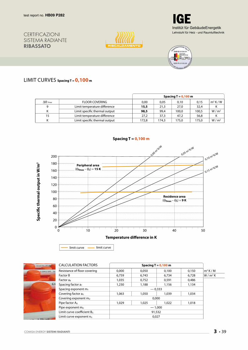
Dq fmax FLOOR COVERING 0,00 0,05 0,10 0,15 m2 K / W 9 Limit temperature difference 15,5 21,3 27,0 32,4 K K Limit specific thermal output 98,5 99,4 100,0 100,5 W / m2
15 Limit temperature difference 27,2 37,3 47,2 56,8 K K Limit specific thermal output 172,8 174,3 175,0 175,0 W / m2
Spacing T = 0,100 m
limit curve limit curve
200
180
160
140
120
100
80
60
40
20
00 10 20 30 40 50
Peripheral area(qfmax – qi) = 15 K
Temperature difference in K
Spec
ific
ther
mal
out
put i
n W
/m2
Spacing T = 0,100 m
0,00 m2 K/W
0,05 m2 K/W
0,10 m2 K/W
0,15 m2 K/W
LIMIT CURVES Spacing T = 0,100 m
CALCULATION FACTORSResistance of floor coveringFactor BFactor aB
Spacing factor aT
Spacing exponent mT
Covering factor aÜ
Covering exponent mÜ
Pipe factor AD
Pipe exponent mD
Limit curve coefficient BG
Limit curve exponent nG
0,000 0,050 0,100 0,150 6,759 6,743 6,734 6,728 1,035 0,752 0,591 0,486 1,230 1,188 1,156 1,134
— 0,333 1,063 1,050 1,039 1,034
0,000 1,029 1,025 1,022 1,018
— 1,00091,5320,027
m2 K / MW / m2 K
Spacing T = 0,100 m
Residence area(qfmax – qi) = 9 K

page of 9 test report no. HB09 P282
RISCALDAMENTO
CERTIFICAZIONI SISTEMA RADIANTERIBASSATO
Institüt für GebäudeEnergetikLehrstuhl für Heiz - und Raumlufttechnik
COMISA spa3 • 40
Dq fmax FLOOR COVERING 0,00 0,05 0,10 0,15 m2 K / W 9 Limit temperature difference 17,5 23,7 29,7 35,4 K K Limit specific thermal output 96,0 98,1 99,6 100,9 W / m2
15 Limit temperature difference 30,7 41,5 52,1 62,0 K K Limit specific thermal output 168,4 172,0 174,7 175,0 W / m2
Spacing T = 0,150 m
limit curve limit curve
200
180
160
140
120
100
80
60
40
20
00 10 20 30 40 50
Peripheral area(qfmax – qi) = 15 K
Temperature difference in K
Spec
ific
ther
mal
out
put i
n W
/m2
Spacing T = 0,150 m
0,00 m2 K/W
0,05 m2 K/W
0,10 m2 K/W
0,15 m2 K/W
LIMIT CURVES Spacing T = 0,150 m
CALCULATION FACTORSResistance of floor coveringFactor BFactor aB
Spacing factor aT
Spacing exponent mT
Covering factor aÜ
Covering exponent mÜ
Pipe factor AD
Pipe exponent mD
Limit curve coefficient BG
Limit curve exponent nG
0,000 0,050 0,100 0,150 6,776 6,757 6,746 6,739 1,035 0,752 0,591 0,486 1,230 1,188 1,156 1,134
— 1,000 1,057 1,046 1,035 1,031
0,000 1,040 1,034 1,029 1,024
— 1,00078,6410,070
m2 K / MW / m2 K
Spacing T = 0,150 m
Residence area(qfmax – qi) = 9 K

page of 9
RISCALDAMENTO
CERTIFICAZIONI SISTEMA RADIANTERIBASSATO
test report no. HB09 P282
Institüt für GebäudeEnergetikLehrstuhl für Heiz - und Raumlufttechnik
3 • 41COmisa enerGY SISTEMI RADIANTI
Dq fmax FLOOR COVERING 0,00 0,05 0,10 0,15 m2 K / W 9 Limit temperature difference 19,4 26,1 32,5 38,7 K K Limit specific thermal output 92,6 95,8 98,3 100,4 W / m2
15 Limit temperature difference 34,1 45,7 56,9 67,7 K K Limit specific thermal output 162,4 168,1 172,5 175,0 W / m2
Spacing T = 0,200 m
LIMIT CURVES Spacing T = 0,200 m
CALCULATION FACTORSResistance of floor coveringFactor BFactor aB
Spacing factor aT
Spacing exponent mT
Covering factor aÜ
Covering exponent mÜ
Pipe factor AD
Pipe exponent mD
Limit curve coefficient BG
Limit curve exponent nG
0,000 0,050 0,100 0,150 6,788 6,768 6,756 6,748 1,036 0,752 0,591 0,486 1,230 1,188 1,156 1,134
— 1,667 1,051 1,041 1,032 1,028
0,000 1,046 1,040 1,035 1,030
— 1,00065,2090,118
m2 K / MW / m2 K
Spacing T = 0,200 m
limit curve limit curve
200
180
160
140
120
100
80
60
40
20
00 10 20 30 40 50
Peripheral area(qfmax – qi) = 15 K
Temperature difference in K
Spec
ific
ther
mal
out
put i
n W
/m2
Spacing T = 0,200 m
0,00 m2 K/W
0,05 m2 K/W
0,10 m2 K/W
0,15 m2 K/W
Residence area(qfmax – qi) = 9 K

page of 9 test report no. HB09 P282
RISCALDAMENTO
CERTIFICAZIONI SISTEMA RADIANTERIBASSATO
Institüt für GebäudeEnergetikLehrstuhl für Heiz - und Raumlufttechnik
COMISA spa3 • 42
LIMIT CURVES Spacing T = 0,250 m
CALCULATION FACTORSResistance of floor coveringFactor BFactor aB
Spacing factor aT
Spacing exponent mT
Covering factor aÜ
Covering exponent mÜ
Pipe factor AD
Pipe exponent mD
Limit curve coefficient BG
Limit curve exponent nG
0,000 0,050 0,100 0,150 6,795 6,775 6,763 6,755 1,036 0,753 0,591 0,486 1,230 1,188 1,156 1,134
— 2,333 1,045 1,035 1,028 1,024
0,000 1,051 1,046 1,041 1,035
— 1,00051,7610,169
m2 K / MW / m2 K
Spacing T = 0,250 m
limit curve limit curve
200
180
160
140
120
100
80
60
40
20
00 10 20 30 40 50
Peripheral area(qfmax – qi) = 15 K
Temperature difference in K
Spec
ific
ther
mal
out
put i
n W
/m2
Spacing T = 0,250 m
0,00 m2 K/W
0,05 m2 K/W
0,10 m2 K/W
0,15 m2 K/W
Residence area(qfmax – qi) = 9 K
Dq fmax FLOOR COVERING 0,00 0,05 0,10 0,15 m2 K / M 9 Limit temperature difference 21,0 27,8 34,4 41,0 K K Limit specific thermal output 86,6 90,8 94,1 96,9 W / m2
15 Limit temperature difference 36,8 48,8 60,3 70,0 * K K Limit specific thermal output 151,8 159,3 165,1 165,6 ** W / m2
Spacing T = 0,250 m
* Specific thermal output with the limits of max temperature difference** Max temperature difference for the pipe in K
page of 9
RISCALDAMENTO
CERTIFICAZIONI SISTEMA RADIANTERIBASSATO
test report no. HB09 P282
Institüt für GebäudeEnergetikLehrstuhl für Heiz - und Raumlufttechnik
3 • 43COmisa enerGY SISTEMI RADIANTI
LIMIT CURVES Spacing T = 0,300 m
CALCULATION FACTORSResistance of floor coveringFactor BFactor aB
Spacing factor aT
Spacing exponent mT
Covering factor aÜ
Covering exponent mÜ
Pipe factor AD
Pipe exponent mD
Limit curve coefficient BG
Limit curve exponent nG
0,000 0,050 0,100 0,150 6,799 6,780 6,769 6,760 1,036 0,753 0,591 0,486 1,230 1,188 1,156 1,134
— 3,000 1,040 1,031 1,024 1,021
0,000 1,053 1,049 1,044 1,039
— 1,00038,0830,241
m2 K / MW / m2 K
Spacing T = 0,300 m
limit curve limit curve
200
180
160
140
120
100
80
60
40
20
00 10 20 30 40 50
Peripheral area(qfmax – qi) = 15 K
Temperature difference in K
Spec
ific
ther
mal
out
put i
n W
/m2
Spacing T = 0,300 m
0,00 m2 K/W
0,05 m2 K/W
0,10 m2 K/W
0,15 m2 K/W
Residence area(qfmax – qi) = 9 K
Dq fmax FLOOR COVERING 0,00 0,05 0,10 0,15 m2 K / M 9 Limit temperature difference 22,4 29,7 36,5 43,5 K K Limit specific thermal output 80,4 86,1 90,4 94,3 W / m2
15 Limit temperature difference 39,2 52,0 64,0 70,0 * K K Limit specific thermal output 141,1 151,0 158,6 151,9 ** W / m2
Spacing T = 0,300 m
* Specific thermal output with the limits of max temperature difference** Max temperature difference for the pipe in K

COMISA spa3 • 44
page of 9 test report no. HB09 P276
RISCALDAMENTO
CERTIFICAZIONI SISTEMA RADIANTERIBASSATO
Institüt für GebäudeEnergetikLehrstuhl für Heiz - und Raumlufttechnik
30 mm
32 mm 62 mm
Battiscopa
Fascia perimetrale isolante Rivestimento Massetto additivato
Rete elettrosaldata Ø 2 mm Tubo PE-RT/AL/PE-RT Ø 16x2Tubo PE-Xa Ø 17x2
Pannello isolante
Soletta
THERMOCOnCePtRIBASSATO
9. Construction drawing of test sample:
10. Picture of test area:
The test area was built on 25.3.2009 in the Institut. The used material was sended directy by the client. The construction is equal to the nominal construction of the drawing and the technical documents.
11. Conformity of the technical documents
The system is type A of DIN 18560 part. 2. The sketch on the tecnical documents are in acc. to EN 1264 part. 4. The official technical documents should be sended to the Institut within 6 months.

3 • 45COmisa enerGY SISTEMI RADIANTI
Test report for specific thermal outputof floor heating constructionin acc. to EN 1264
Type RIBASSATO, load distribution layer: 45 mm, pipe: 16 x 2 mm
test report no.: H.0905.P.632.COM
Stuttgard, 30.04.2009
The report shall not be reproduced expect in full without the written approval of the testing lab.The test results relase only to the items tested
The test laboratoryis accredit in acc. to ISO/IEC 17025 by DAR.Acceptances from certification bodies:DINCERTOCO / RAL / AFNOR / BSI / AENOR
sistema radianteRIBASSATO
Institüt fürGebäudenEnergetik
Lehrstuhl fürHeiz-undRaumlufttechnik
Universität Stuttgart
RAFFRESCAMENTO

Institüt für GebäudeEnergetikLehrstuhl für Heiz - und Raumlufttechnik
COMISA spa3 • 46
page of 9
Institüt für GebäudeEnergetikLehrstuhl für Heiz - und Raumlufttechnik
test report no. H.0905.P.632.COM
CERTIFICAZIONI SISTEMA RADIANTERIBASSATO RAFFRESCAMENTO
1. Decription of the test method: The heating output of the looked floor system can be determined to EN 1264 part. 2
In part. 5 of EN 1264 instructions are given which changes are to be expcted in the output (heating case and chilled case), if the arrangement of the space surfaces is changed.
Thus the arrangement on the ground is, e.g., in the chilled case the case with the lowest output values, while in the heating case the arrangement on the ground proves the highest values.
2. Test results: 2.1 PROCEDURE OF TESTING: The standard specific thermal output the heating case is calculated to EN 1264 for 4 standard layers (R1 to R4):
(Rl = 0,0; 0,05; 0,1 and 0,15 m2 K/W
These theoretical values of the resistance cover the really seeming floor covering to a great extent, so that for the laters use with these values or interpolations the system can be laid out.
2.2 RESULTS OF HEATING CASE IN ACC. TO EN 1264 PART. 2: Characteristic curves q = kH* DqH
ADD. FLOOR COVERING 0,00 0,05 0,10 0,15 m2 K/W
Spacing T Equivalent coefficient for heat transfer kH
0,050 m 7,534 5,372 4,167 3,403 W/m2 K
0,100 m 6,347 4,673 3,709 3,083 W/m2 K
0,150 m 5,485 4,139 3,351 2,823 W/m2 K
0,200 m 4,760 3,675 3,029 2,584 W/m2 K
0,250 m 4,131 3,262 2,739 2,366 W/m2 K
0,300 m 3,594 2,901 2,480 2,170 W/m2 K

Institüt für GebäudeEnergetikLehrstuhl für Heiz - und Raumlufttechnik
3 • 47COmisa enerGY SISTEMI RADIANTI
test report no. H.0905.P.632.COM
RAFFRESCAMENTO
CERTIFICAZIONI SISTEMA RADIANTERIBASSATO
Institüt für GebäudeEnergetikLehrstuhl für Heiz - und Raumlufttechnik
2.3 RESULTS OF CHILLED CASE IN ACC. TO EN 1264 PART. 5:
The results for the floor heating system in acc. to EN 1264 part. 2 has to be transmitted by calculation method in acc. to EN 1264 part. 5
ADD. FLOOR COVERING a (W/m2 K) DRm = 1/a - 1/10,8 (m2 K/W) Fussboden 10,8 0,0000
Fussboden 6,5 0,0613
Wand 8,0 0,0324
Wand 8,0 0,0324
Decken 6,5 0,0613
Decken 10,8 0,0000
Characteristic curves for the case of chilled floor
The cooling output of a floor system is reduced with the otherwise same conditions compared with the output of an under-floor heating system. A cause for this are the changed conditions on the heat transfer by convection on the surface of the floor. From part 5 on EN 1264 the respective heat transfer coefficients are known.
For the looked floor type THERMOCONCEPT STANDARD the following output values arise.
q = kH* DqH
mit
Dq Temperature difference
RA 0,05 0,10 0,15 0,20 0,25 0,30 KH1 5,036 4,430 3,959 3,541 3,166 2,834 KH2 3,964 3,554 3,227 2,930 2,659 2,418 KH3 3,268 2,968 2,723 2,498 2,293 2,108 KH4 2,780 2,547 2,356 2,178 2,015 1,868
Tabella 3: Coefficient s of the characteristic curves for the different standard layers as a function of the pipe distance RA.

Institüt für GebäudeEnergetikLehrstuhl für Heiz - und Raumlufttechnik
COMISA spa3 • 48
page of 9
Institüt für GebäudeEnergetikLehrstuhl für Heiz - und Raumlufttechnik
test report no. H.0905.P.632.COM
CERTIFICAZIONI SISTEMA RADIANTERIBASSATO RAFFRESCAMENTO
90
80
70
60
50
40
30
20
10
00 2 4 6 8 10 12 14 16
Temperature difference in K
Spec
ific
ther
mal
out
put i
n W
/m2
Figure 1: cooling output in dependence of the temperature distance room - water for pipe distance RA 50 mm
80
70
60
50
40
30
20
10
00 2 4 6 8 10 12 14 16
Temperature difference in K
Spec
ific
ther
mal
out
put i
n W
/m2
Figure 2: cooling output in dependence of the temperature distance room - water for pipe distance RA 100 mm
Rl = 0,0 m2 K/W
Rl = 0,5 m2 K/W
Rl = 0,10 m2 K/W
Rl = 0,15 m2 K/W
Rl = 0,0 m2 K/W
Rl = 0,5 m2 K/W
Rl = 0,10 m2 K/W
Rl = 0,15 m2 K/W
The figures 1 to 6 show this connection again in graphic form.

Institüt für GebäudeEnergetikLehrstuhl für Heiz - und Raumlufttechnik
3 • 49COmisa enerGY SISTEMI RADIANTI
test report no. H.0905.P.632.COM
RAFFRESCAMENTO
CERTIFICAZIONI SISTEMA RADIANTERIBASSATO
Institüt für GebäudeEnergetikLehrstuhl für Heiz - und Raumlufttechnik
70
60
50
40
30
20
10
00 2 4 6 8 10 12 14 16
Temperature difference in K
Spec
ific
ther
mal
out
put i
n W
/m2
Figure 3: cooling output in dependence of the temperature distance room - water for pipe distance RA 150 mm
60
50
40
30
20
10
00 2 4 6 8 10 12 14 16
Temperature difference in K
Spec
ific
ther
mal
out
put i
n W
/m2
Figure 4: cooling output in dependence of the temperature distance room - water for pipe distance RA 200 mm
Rl = 0,0 m2 K/W
Rl = 0,5 m2 K/W
Rl = 0,10 m2 K/W
Rl = 0,15 m2 K/W
Rl = 0,0 m2 K/W
Rl = 0,5 m2 K/W
Rl = 0,10 m2 K/W
Rl = 0,15 m2 K/W

COMISA spa3 • 50
RISCALDAMENTO
Institüt für GebäudeEnergetikLehrstuhl für Heiz - und Raumlufttechnik
page of 9
Institüt für GebäudeEnergetikLehrstuhl für Heiz - und Raumlufttechnik
test report no. H.0904.P.615.COM
CERTIFICAZIONI SISTEMA RADIANTERIBASSATO RAFFRESCAMENTO
Figure 5: cooling output in dependence of the temperature distance room - water for pipe distance RA 250 mm
60
50
40
30
20
10
00 2 4 6 8 10 12 14 16
Temperature difference in K
Spec
ific
ther
mal
out
put i
n W
/m2
Figure 6: cooling output in dependence of the temperature distance room - water for pipe distance RA 300 mm
Rl = 0,0 m2 K/W
Rl = 0,5 m2 K/W
Rl = 0,10 m2 K/W
Rl = 0,15 m2 K/W
45
40
35
30
25
20
15
10
5
00 2 4 6 8 10 12 14 16
Temperature difference in K
Spec
ific
ther
mal
out
put i
n W
/m2
Rl = 0,0 m2 K/W
Rl = 0,5 m2 K/W
Rl = 0,10 m2 K/W
Rl = 0,15 m2 K/W