site 5 repair and replacement - therma-tru doors · pdf filesite 5 repair and replacement ......
TRANSCRIPT

Repair and Replacem
ent
SITE 5 2017 5.1
SITE 5 Repair and ReplacementRepairing Therma-Tru Door Slabs .............................................................................................................................. 5.3Sidelite Slab Replacement ........................................................................................................................................... 5.6Mull Post Replacement .............................................................................................................................................. 5.13Weatherstrip Replacement ........................................................................................................................................ 5.21Adjustable Sill Threshold Replacement ................................................................................................................... 5.22Basic Fixed Sill Vinyl Threshold Replacement ........................................................................................................ 5.24Doorlite Glass and Frame Replacement ................................................................................................................... 5.27Storm Door Strip Application (Continuous Sill) ...................................................................................................... 5.29

Repa
ir an
d Re
plac
emen
t
5.2 2017 SITE 5
Repair and Replacem
ent
SITE 5 2017 5.3
Repairing Therma-Tru Door Slabs
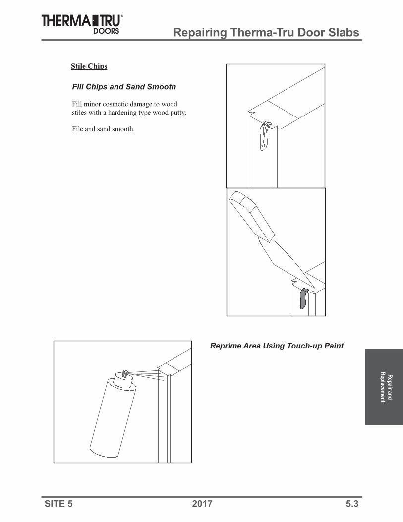
Stile Chips
Fill Chips and Sand Smooth
Fill minor cosmetic damage to wood stiles with a hardening type wood putty.
File and sand smooth.
Reprime Area Using Touch-up Paint

Repa
ir an
d Re
plac
emen
t
5.4 2017 SITE 5
Repairing Therma-Tru Door Slabs
Steel Door Dent Repair
Clean and Roughen Surface
Clean surface surrounding dent.
Roughen using 100 grit sandpaper.
If possible, do not sand through the existing factory-applied primer.
Sand Dent Repair
Sand repair using a large sanding blockor orbital power sander with 220 grit sandpaper.
Fill Dent
Fill dent using Therma-Tru Dent Repair Kit (Part # MS00DRK) or an automotive body-filler compound.
Smooth using a wide-blade putty knife.
Overfill to account for shrinkage and sanding.

Repair and Replacem
ent
SITE 5 2017 5.5
Repairing Therma-Tru Door Slabs
For minor scratches in Classic-Craft Canvas, Oak, Rustic or Fiber-Classic doors, use Classic-Craft & Fiber-Classic Primer (Part # MSCCAB-01) to touch up.
For minor scratches in Classic-Craft Mahogany doors, use Primer (Part # MSCCMAB) to touch up.
For deep scratches, fill with crayon or patch pencil.
Therma-Tru does not recommend any other repair procedures for composite doors.
Re-prime Repair Area(s)
If bare metal was exposed, paint entire repair area with a primer containing rust inhibitors.
Re-prime repaired area using Therma-Tru touch-up primer. If a rust inhibiting primer was used, let dry thoroughly before applyingTherma-Tru touch-up primer.
THERMA-TRU TOUCH-UP PRIMERS
For minor scratches in Smooth-Star doors, use Smooth-Star White Primer (Part # MSWHSABP-03) to touch up.
Description Part NumberSteel White Primer MSWHABP-01
Classic-Craft Canvas, Oak, Rustic, and Fiber-Classic Primer MSCCAB-01Classic-Craft Mahogany Primer MSCCMAB-01
Smooth-Star Primer MSWHSABP-03Steel Edge Door Primer MSWHSED
Steel Frame Primer MSWHAF2
Classic-Craft, Fiber-Classic and Smooth-Star Skin Repair

Repa
ir an
d Re
plac
emen
t
5.6 2017 SITE 5
Sidelite Slab Replacement
Remove Cove Molding andInside Vertical Casing if applicable
Remove and set aside cove molding.
If post between sidelite and door is two“mulled” jambs, remove casing there also.
Locate Fasteners
Find fasteners by running a puttyknife blade in the margins andmarking the locations.
Tack on Protective Strips
Tack on softwood strips to protect jamband mullion faces adjacent to sideliteslab.

Repair and Replacem
ent
SITE 5 2017 5.7
Sidelite Slab Replacement
Cut Through Fasteners
Use a reciprocating saw with a metalcutting blade to cut through fasteners.
Run sawblade in margin.
Remove softwood strip.
Cut Sealant Joints
On outside face of unit, use putty knifeand cut through sealant joints along headand at sides.

Repa
ir an
d Re
plac
emen
t
5.8 2017 SITE 5
Sidelite Slab Replacement
Remove Slab
Push slab through from outside.
Prepare Opening for New Slab
Cut away and clean off all old caulking.
Cut away all old fasteners flush withFrame.

Repair and Replacem
ent
SITE 5 2017 5.9
Sidelite Slab Replacement
Seal Perimeter
Apply 1/4” bead of (Elastomeric orPolyurethane) sealant around entireperimeter on jamb and/or mullion stops.
Inswing Sill
Apply a generous amount of (Elastomeric or Polyurethane)sealant at joints where sill andjamb/mullion meet.
Apply a 1/4” bead of (Elastomericor Polyurethane) sealantapproximately 1” aboveweatherstrip kerf, 6” long.
Head
Sealant
Sealant
Sealant
Mullion
Mullion system shown
Outswing Sill
Apply a 1/4” bead of
sealant on saddle surface thatcontacts door face.
.
(Elastomeric or Polyurethane)
Apply a generous amount ofsealant at joints where sill andjamb/mullion meet.
Apply a 1/4” bead of (Elastomericor Polyurethane)sealant approx1” above weatherstrip kerf, 6”long.
Inswing
Outswing
Weatherstripchannel

Repa
ir an
d Re
plac
emen
t
5.10 2017 SITE 5
Sidelite Slab Replacement
Staple
Exterior Exterior
Caulk Door Bottom
Select a (Elastomeric or Polyurethane) sealant that provides excellent adhesion to both plastic and wood.
Apply a 1/4” bead of (Elastomeric or Polyurethane) sealant to top surface of door bottom.
Attach Door Bottom
Note:
Fasten door bottom to sidelite slab with 1” staples or #8-15 x 3/4” Phillips dual angle wafer headtype 17 gimlet point screws.
For 14” and larger slabs use 5 or more fasteners.
SealantSealant
Sealant
Staple
Inswing
Inswing
Inswing
Outswing
Outswing
OutswingCaulk Door BottomApply (Elastomeric or Polyurthane) sealant along channel on bottom of inactive door bottom.
It is recommendedto use an extra bead of sealant in High Exposure Markets.

Repair and Replacem
ent
SITE 5 2017 5.11
Sidelite Slab Replacement
Install New Sidelite Slab
Inswing
Outswing
Inswing - Install inactive fixed panel by tilting bottom edge of panel so inactive door bottom aligns with sill attachment flange.
Attachment Flange
Mullion system shown
Mullion system shown
ShimTo ensure proper seal of inactive door bottomagainst sill, shim head of inactive fixed panel.
Locate shims near corners and slide shims between head jamb and inactive panel.
A putty knife may be required for this operation.
Be careful not to damage face of panel.
Shim Inactive Fixed Panel
Install Sidelite Into Frame
,
Place sill end first, mating plastic bottom tosill if necessary.
Use putty knife blade at top to aid insertionof slab in frame.
Sidelite panels are nominally 1/16” narrowerthan frame opening, for 1/32” clearance oneach side.

Repa
ir an
d Re
plac
emen
t
5.12 2017 SITE 5
Sidelite Slab Replacement
Re-apply Cove Molding andInside Vertical Casing if applicable
Re-apply cove molding and casing to thenew sidelite slab unit.
Fasten New Sidelite Slab
Space four fasteners along both sides.
“Mulled” JambApplication
Drill angled pilot holesthrough frame.Use 2” exterior gradescrews and fasten frame to slab at pilot holes.
Sink screw head in soas not to interfere withmullion casing (appliedlater).
Mullion Application
Fasten through mullionusing 2” finishing nails.
2” drywallscrew
Pilot hole
2”finishingnail

Repair and Replacem
ent
SITE 5 2017 5.13
Mull Post Replacement
Remove Active Door
Unlatch door and remove hinge pins.
Carefully remove door and set aside.
Remove Long Hinge Screws
NOTE: Inactive slab is fastened to mullionwith four long (2-1/2”) hinge screws.
Locate and remove long screws. Set aside.
Remove Cove Molding andInside Vertical Casing if applicable
Remove and set aside cove molding frominactive panel and set aside.
If post is two “mulled” jambs, remove vertical casing.

Repa
ir an
d Re
plac
emen
t
5.14 2017 SITE 5
Mull Post Replacement
Remove Any AdditionalMullion Side Fastening
Examine mullion carefully to ensureno other staples or screws were usedto fasten slab.
Run a putty knife blade down marginbetween slab and mullion to double-check.
If any fasteners are found, using a reciprocating saw with a metal-cutting blade, slice throughfasteners. Run sawblade in margin.
Cut Sealant Joints
On outside face of unit, use a putty knifeand cut through sealant joints along headand at sides.

Repair and Replacem
ent
SITE 5 2017 5.15
Mull Post Replacement
Remove Slab
Push slab through from outside.
Prepare Opening for New Slab
Cut away and clean off all old caulking.
Cut away all old fasteners flush withFrame.

Repa
ir an
d Re
plac
emen
t
5.16 2017 SITE 5
Mull Post Replacement
Adjustable Sill Systems:
Cut mull post loose as close to head and sill as possible.
Use a chisel to split ends of mull post clean from head and sill mortise pockets.
Cut away all old fasteners flush with head frame and sill substrate. Cut away and clean off all old caulk.
CAUTION:
Remove corner seal pad and adjustable saddle from sill.
Cornersealpad
AdjustableSaddle

Repair and Replacem
ent
SITE 5 2017 5.17
Mull Post Replacement
Install New Mull Post
Apply Elastomeric or Polyurethane sealant to bottom end of mull post and insert into sill detail.
Pre-drill holes on an angle through mull post and then secure with screws into sill and head frame.
Slide head end of mull post into head mortise pocket.
2” exterior grade screws
Pilot hole
Sealant
Mullion end cut for adjustable sill shown.
Head Jamb
Mullion

Repa
ir an
d Re
plac
emen
t
5.18 2017 SITE 5
Mull Post Replacement
Seal Perimeter
Apply 1/4” bead of (Elastomeric orPolyurethane) sealant around entireperimeter on jamb and/or mullion stops.
Inswing Sill
Apply a generous amount of (Elastomeric or Polyurethane)sealant at joints where sill andjamb/mullion meet.
Apply a 1/4” bead of (Elastomericor Polyurethane) sealantapproximately 1” aboveweatherstrip kerf, 6” long.
Head
Sealant
Sealant
Sealant
Mullion
Mullion system shown
Outswing Sill
Apply a 1/4” bead of
sealant on saddle surface thatcontacts door face.
.
(Elastomeric or Polyurethane)
Apply a generous amount ofsealant at joints where sill andjamb/mullion meet.
Apply a 1/4” bead of (Elastomericor Polyurethane)sealant approx1” above weatherstrip kerf, 6”long.
Inswing
Outswing
Weatherstripchannel

Repair and Replacem
ent
SITE 5 2017 5.19
Mull Post Replacement
Install Sidelite Into Frame
Inswing
Outswing
Inswing - Install inactive fixed panel by tilting bottom edge of panel so inactive door bottom aligns with sill attachment flange.
Attachment Flange
Mullion system shown
Mullion system shown
ShimTo ensure proper seal of inactive door bottomagainst sill, shim head of inactive fixed panel.
Locate shims near corners and slide shims between head jamb and inactive panel.
A putty knife may be required for this operation.
Careful not to damage face of panel.
Shim Inactive Fixed Panel
Install Sidelite Into Frame
,
Place sill end first, mating plastic bottom tosill if necessary.
Use putty knife blade at top to aid insertionof slab in frame.
Sidelite panels are nominally 1/16” narrowerthan frame opening, for 1/32” clearance oneach side.

Repa
ir an
d Re
plac
emen
t
5.20 2017 SITE 5
Mull Post Replacement
Re-apply Cove Molding andInside Vertical Casing if applicable
Re-apply cove molding to the new sideliteSlab unit.
Finish Up
Replace jamb casing.
Replace active slab.
Examine exterior joints betweeninactive slab, frame and sill.Apply additional Elastomeric or Polyurethane sealant at joints if required.

Repair and Replacem
ent
SITE 5 2017 5.21
Weatherstrip Replacement
Press-In Weatherstrip
Remove existing weatherstrip from jambs.
Replace with new compression weatherstrip.
Nail-In Weatherstrip
Use a sharp chisel or putty knifeto break nails between weatherstipand jamb.
Remove weatherstrip.
Apply compression weatherstrip to jamb.

Repa
ir an
d Re
plac
emen
t
5.22 2017 SITE 5
Adjustable Sill Threshold Replacement
Remove Corner Seal Pads
Break any sealant bonds.
Remove corner seal pads.
Clean off excess sealant.
Remove Existing Threshold
Unscrew adjustment screws toremove threshold.
Carefully remove sill gasket fromaluminum channel after adjustablethreshold is removed.
Cornersealpad
Adjustable Saddle
AdjustableSaddle

Repair and Replacem
ent
SITE 5 2017 5.23
Adjustable Sill Threshold Replacement
Fasten Threshold to Sill
NOTE: It may be necessary to trim new threshold so it fits properly. Trim both ends equally.
Insert threshold and screw downadjustment screws.
Insert sill gasket into aluminumchannel after adjustable threshholdhas been installed.
Make any sill adjustments, ifnecessary, for a proper seal.
Apply Corner Seal Pads
After final threshold adjustments,apply a bead of Elastomeric or Polyurethane sealant at sill jamb joint
Remove paper backing from pad and apply pad to jamb with bottomedge down against sealant, tuckingbehind weatherstrip.
Cornersealpad
AdjustableSaddle
AdjustableSaddle

Repa
ir an
d Re
plac
emen
t
5.24 2017 SITE 5
Basic Fixed Sill Vinyl Threshold Replacement
Remove Corner Seal Pads
Break any sealant bonds.
Remove corner seal pads.
Clean off excess sealant.
Cornerseal pad
Remove Staples and/or Screws
Pull out staples that fasten vinyl thresholdand any screws that may be fastened throughthe top of the threshold.
Pull off Vinyl Threshold
Carefully remove vinyl threshold so notto damage aluminum approach. It may benecessary to pry threshold off with a screwdriver.

Repair and Replacem
ent
SITE 5 2017 5.25
Basic Fixed Sill Vinyl Threshold Replacement
Fasten Threshold
With threshold in place, fasten back face downwith staples.
Install Vinyl Threshold
NOTE: It may be necessary to trim newthreshold so it fits properly.
Hook vinyl nose into aluminum grooveand rotate down around wood substrate.
Replacement Vinyl 3/0 - ISL3FCAP330-R6/0 - ISL3FCAP470-R
(for U1REV size)
Replacement Vinyl (Woodgrain)
3/0 - RPSLIV397W 6/0 - RPSLIV697W
Replacement Vinyl 3/0 - RPSLIV393 6/0 - RPSLIV693
(for Book and U1 sizes)(for Book and U1 sizes)

Repa
ir an
d Re
plac
emen
t
5.26 2017 SITE 5
Basic Fixed Sill Vinyl Threshold Replacement
Apply Corner Seal PadsPlace a bead of Elastomeric orPolyurethane sealant at corners where threshold meets jambs.
Remove paper backing from pad.
Position pad tightly to threshold and flush with inside edge of threshold, tucking behind weather-strip.
Apply one pad at each side.
Sealant
Corner sealpad

Repair and Replacem
ent
SITE 5 2017 5.27
Doorlite Glass and Frame Replacement
Remove Door from System
Place in horizontal position beforeremoving lite for safety purposes.
Remove plugs and screws from doorliteto separate lite frames.
Save plugs and screw for re-use.
Remove doorlite from door or sidelite.
Remove Glass from Doorlite Frame
Use a heat gun or warm air from a hair dryer tosoften glazing compound.
Remove glass by cutting through glazing sealant withutility knife.
Scrape off glazing sealant as much as possible from glassand frame. Remove the remaining residue with mineral spirits and glass cleaner.
from glass only
Replace Glass and/or Frame
Apply foam glazing tape (Part #RPGZGS) directlyto the glass edges, taling care to make tight buttjoints at corners. Do not overlap. Do not stretch.
NOTE: Be sure surfaces are clean and drybefore applying sealant.
Align and insert glass onto exterior frame, pressing in place to ensure a good bond.

Repa
ir an
d Re
plac
emen
t
5.28 2017 SITE 5
Doorlite Glass and Frame Replacement
Apply Glazing Tape (if damaged)
Replace existing foam glazing tape ifdamaged. (Part # RPGLZTP)
DO NOT stretch.
Overlap at corners.
Press on lightly with fingers. Then witha roller tool, fully bond gasket using firmpressure.
Insert Interior Frame and Drive Screws with #2 Phillips Bit
Ensure correct alignment of screwbosses.
Ensure frame edges are well-seated.
Drive screws.
Press-fit screw plugs into frame holes.
Re-hang door.
Position Lite into Opening
Place lite against bottom edge of cutout to prevent shifting.
Center lite in cutout side-to-side.
Interior side
Exterior lite frame(half with glass)
NOTE: When installing multiple lites, use a straight edge to check alignment of lites before securing in place.

Repair and Replacem
ent
SITE 5 2017 5.29
Storm Door Strip Application (Continuous Sill)
Make Storm Door Adapter Strips
4-9/16” Jamb Adapter
1-15/32”1-1/16”
6°
80-21/32”
1-15/32”1”
6°
80-1/16”
1-15/32”1-1/16”
6°
80-7/8”
1-15/32”3”
6°80-1/4”
Use standard mull casings(Part No. MSMLCAS).Cut to length as shown,and bevel one end to make base and face adapterstrips.
One set (2 pieces - faceand base adapter) is usedat each mullion.
Face Adapter Strip Base Adapter Strip
Face Adapter Strip Base Adapter Strip
6-9/16” Jamb Adapter
Purchase or fabricate a base adaptor strip as shown (Part numberMSSDADP).
Use one standard mull casing (Part No. MSMLCAS). Cut to length as shown, and bevel one end to make a face adapter strip.
One set (2 pieces - face and base adapter) is used at each mullion.

Repa
ir an
d Re
plac
emen
t
5.30 2017 SITE 5
Storm Door Strip Application (Continuous Sill)
Apply Storm Door Adapter
First fasten base adapter strips using #10 x 2” screws for 4-9/16” jambs or #10 x 4” screws for 6-9/16” jambs as shown.
Apply face adapter strips directly over base adaptors using 2-1/2” staples.
Caulk at head joints
Caulk at sill joints #10 x 2” screws (4-5/8” jambs)or
#10 x 4” screws (6-5/8” jambs)
Sill removed for clarity.
Base adapter
Face adapter
2-1/2” Staples

Repair and Replacem
ent
SITE 5 2017 5.31
7/8” Astragal Spring Clip Replacement Instructions
7/8” AstragalSpring Clip
Replacement Instructions
The following instructions are for use at the job site.
The hardware pack contains all the necessaryhardware and fasteners needed to complete this
installation.
Read all instructions before starting.
P/N: SPRREPLINST-RRev. A 2/4/16
Pack Contents
Hex Key
(2) Spring Clip
Therma-Tru is a registered trademark of Therma-Tru Corp.© 2016 Therma-Tru Corp.
1750 Indian Wood CircleMaumee, Ohio 43537
419-891-7400

Repa
ir an
d Re
plac
emen
t
5.32 2017 SITE 5
7/8” Astragal Spring Clip Replacement Instructions
1 REMOVE TRIM STRIP
With the astragal slide bolt assembly in the fully engaged position, remove the trim strip closest to the spring clip by pulling it out by hand.
2a REMOVE DAMAGED SPRING CLIP2Loosen the set screw closest to the spring clip using the provided hex key. Remove the pan head screw holding the spring clip in place.
Remove and discard the damaged spring clip.
Set screw
Pan headscrew

Repair and Replacem
ent
SITE 5 2017 5.33
7/8” Astragal Spring Clip Replacement Instructions
4 REINSTALL TRIM STRIPINSTALL NEW SPRING CLIP3Insert the new spring clip under the slide bolt assembly, making sure to slide under the set screw.
Align the hole in the spring clip with the hole in the astragal. Fasten in place with the pan head screw.
Tighten the set screw to hold the other end of the spring clip for proper operation. This step is critical to the performance of the astragal in the field.
Locate the trim strip to align with the strike plate, then press the strip into place by hand.
Check the operation of the slide bolt.
Pan headscrew
Set screw