site keynotes general notes millennium...
TRANSCRIPT

A
LIGHT POST DETAIL
LEGAL DESCRIPTIONLOT 5, BLOCK 241PLAN 032 485SHERWOOD PARK, AB
EXTERIOR LIGHTING CONTROLS
GENERAL NOTESSITE KEYNOTES
UTILITIES CONTACT INFO
SITE PLAN - ELECTRICAL
SYMBOL LEGENDSYMBOL DESCRIPTION
SATELLITE VIEW
PREMIER WAY
MILLENNIUMOFFICE
SOUTH EAST PYLON LOCATION
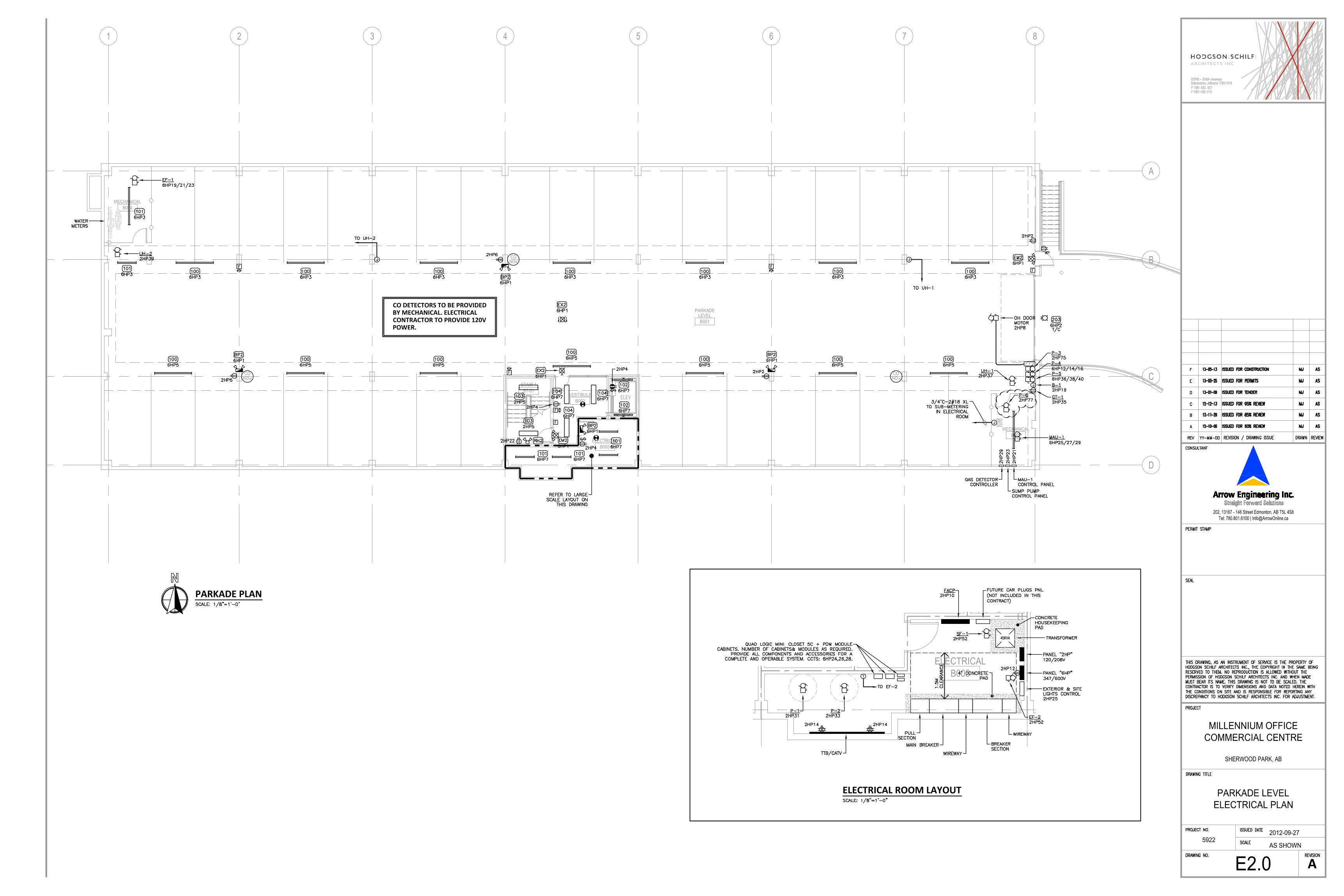
CO DETECTORS TO BE PROVIDEDBY MECHANICAL. ELECTRICALCONTRACTOR TO PROVIDE 120VPOWER.
A
PARKADE PLAN
ELECTRICAL ROOM LAYOUT

TEMPORARY POWER FOR EM/EX LIGHTING FORUNITS 101 & 102 WILL BE PROVIDED FROM PANEL2102A LOCATED @ UNIT 102.
TEMPORARY POWER FOR EM/EX LIGHTING FORUNITS 104 & 105 WILL BE PROVIDED FROM PANEL2105A LOCATED @ UNIT 105.
A
MAIN FLOOR PLAN
GENERAL NOTES
KEYNOTES
TYPICAL TENANT PANELS 103, 106, 206 & 306
204, 205, 207, 304,, 305 & 307
TYPICAL TENANT PANELS 102, 104, 105, 107,

TEMPORARY POWER FOR EM/EX LIGHTING FORUNITS 204, 205 & 207 WILL BE PROVIDED FROMPANEL 2206A LOCATED @ UNIT 206.
A
SECOND FLOOR PLAN
KEYNOTES

TEMPORARY POWER FOR EM/EX LIGHTING FORUNITS 304, 305 & 307 WILL BE PROVIDED FROMPANEL 2306A LOCATED @ UNIT 306.
A
THIRD FLOOR PLAN
KEYNOTES
ELEVATOR MACHINE ROOM KEYNOTES
ELEVATOR ROOM DETAIL

1.00 GENERAL
1.01 References
Refer to the Electrical Specifications Sections for:
General Requirements
Drawings, Approvals and Alternates
Conduit Wire and Cable
Distribution Panels and System Operating Voltages for Meters
Canadian Electrical Code and Electrical Inspections
1.02 Sub-Metering System
.1 To consist of Measurement Canada Approved electronic multi-meters, socket meters, current transformers, and a communications system as shown on drawings and
described herein. The system is the QUADLOGIC ELECTRONIC METERING SYSTEM.
.2 Meters to be used for Revenue Billing of tenant electricity usage, demand and power factor and carbon emissions reporting.
.3 The meters will be capable of remote communication, utilizing one of or a combination of the following systems:
a. Power Line Carrier (PLC): communications over existing power distribution network. The signals will pass through 1 potential transformer. A
Transponder(s) installed on the 347/600v distribution collects the meter data. The Operator collects data from the Transponder via modem or RS232
connection.
b. Data Link (DLC): RS485 communications via a twisted shielded 4-wire (2 separate pairs) daisy-chained between meters in conduit. Provided by electrical
contractor.
c. Ethernet: Lantronix Ethernet to serial adapter installed in 1 meter or Transponder per site.
.3 Optional: Provide web-based meter reading, reporting and billing service for a annual or monthly fee. Software to be capable of billing tenants at current utility rates,
providing daily, monthly and yearly profiles, carbon emissions reporting, benchmark and baseline reporting.
.4 System to have backup storage power to key components so that no data is lost during power outages. The system shall continue to function after resumption of
power. Data to be retained for 8500 hours with a 20-year shelf life.
.5 Failure of the building electrical normal power system shall not result in loss of data and will not require manual restarting of the metering system.
1.03 Shop Drawings
.1 Submit Quadlogic Installation and Shop Drawings and metering system data to meet the specifications:
a. System riser, one line and panel wiring diagram
b. Manufacturer's system and component connection diagram
c. Measurement Canada approvals for meters and current transformers
.2 Shop drawings to be reviewed by Owner, General Contractor, Electrical Engineer, and Electrical Contractor.
1.04 System Measurements
.1 Meters to be complete with a Liquid Crystal Display (LCD) to access all billing measurements and phase diagnostics.
.2 Billing Parameters: kWHr standard, all other parameters are optional
KWHR real consumption
KW average demand
KW instantaneous demand
KVAH apparent consumption
KVA apparent demand
.3 Phase Diagnostics: Parameters to be displayed for each individual phase of each metered load:
Voltage Phase to neutral for each phase
Amps Instantaneous amperage for each phase
Frq Frequency
kW Instantaneous real energy
kVA Instantaneous apparent energy
kVAR Instantaneous reactive energy
Pf Instantaneous power factor
Pa Phase angle
.4 Data Logging (OPTIONAL)
.1 Logging of kW, kVA, Total Harmonic Distortion, Power Factor and Amperage in customized intervals (5,15, 30, 60 minute)
2.00 PRODUCTS
2.01 Manufacturer
.1The system shall be manufactured by Quadlogic Controls Corporation Inc.
2.02a Meters
.1 Minicloset-5c Multi-Customer Meter 120/208, or 347/600 as shown. Configured for 8-3 meters, 12-2, 6-3, 4-3 meters or 24-1 meters
.2 S20 Socket Meter , 120/240, 120/208, 277/480, 347/600, 480 or 600 DELTA 200 amp self contained meter, configured in 4, 5, 7. For applications with remote
Current Transformers utilize13 jaw .1-10 amp meter c/w meter base and shorting block.
.3 Transmeter RSM-5 Single Customer Meter 120/240, 120/208, 277/480, 347/600, or 600 DELTA. For applications with remote Current Transformers only.
2.02b Current Transformers
.1 5 Amp Secondary CTs, Measurement Canada Approved
Models: 2DARL, 8, 180, 1000, 120, for use with Transformer rated meters
2.02v Meter Bases & Sockets:
.1 13-jaw or 8-jaw meter base to be supplied pre-wired by manufacturer complete with a shorting and test block.
2.03 Meter Communications Options: PLC, DLC, RS232, Modem, Modbus (RS-485)
.1 PLC power line carrier module for meters, signals will pass through 1 transformation. 1 required for each meter that will communicate via PLC.
.2 Transponder (ST5) Scan Transponder collects data from meters via power line network. 1 Transponder required for each 347/600v service.
.3 RS232, 3 wire connection to computer and printer in building. 1 required per system.
.4 19k Baud Internal Modem, installed in a meter or in a Transponder. 1 required per system.
.5 Hard-wired internet connection for remote meter reading.
.6 Provide a cellular IP modem with Static IP address for remote meter reading. Monthly charge for the rental of the modem applies. (OPTIONAL)
.7 Provide a 2-wire RS-485 communication module for connection to a Building Automation System. Meter(s) to be programmed for Modbus protocol.
.8 Provide a Field Server protocol translation with the following output:
BACnet IP, BACnet TS, Lonworks, Modbus TCP. (TBA)
2.04 Pulse Inputs (Optional)
.1 Pulse inputs from gas, water or BTU meters.
.2 Gas/water meter to be supplied with a dry-contact pulse output device
a) Form A
b) Max rate: 5 transitions/sec
c) Min pulse width: 100 m/s
.3 Maximum 4 pulse inputs per S20, RSM5, 48 pulse inputs per Minicloset-5c.
.4 Provide a single pair #18AWG (max 300 ft) from each gas/water meter to the Quadlogic Minicloset-5 or S20
2.05 Warranty
.1 Manufacturer shall warranty the products free from defect for a period of 3 years.
3.00 EXECUTION
3.01 Wiring and Connections
.1 All wiring in conduit to CE Code. Refer to Quadlogic installation drawings.
.2 Metering points shown on Electrical Single Line Drawings.
.3 Provide a dedicated telephone line for remote meter reading and diagnostics of the system.
3.00 EXECUTION
3.01 Wiring and Connections
.1 All wiring in conduit to CE Code. Refer to Quadlogic installation drawings.
.2 Metering points shown on Electrical Single Line Drawings.
.3 Provide a dedicated telephone line for remote meter reading and diagnostics of the system.
3.02 Field Verification, Acceptance & Training
.1 Installation contractor to provide “AS BUILT” - marked up Quadlogic “Record of Metering Installation” sheet(s) indicating each meter, serial no., address, cross
reference, metered tenant(s) and CT ratio. Information to be forwarded to Quadlogic Meter Technician prior to field verification.
.2Quadlogic's representative shall verify, adjust and test the system. Verification to
Division 16 - Electrical Section
SUB METERING SYSTEM
Project No. Page 5
METERING SPECIFICATION February 2009
be carried out with the assistance of the electrical contractor. Upon completion, Quadlogic will issue a “CERTIFICATE OF ACCEPTANCE” to the owner, electrical consultant and
contractor.
.3 QMC representative shall demonstrate operation of the system as follows:
a. Meter readings at the meter
b. Phase Diagnostics
c. Provide manual of installed system.
.4 Installation and setup of system software on owner's computer. (OPTIONAL)
.5 Provide training and software manual for owner's staff. (OPTIONAL)
3.03 Measurement Canada Requirements
.1 Quadlogic shall supply to site REVENUE meters that have been "sealed" by Measurement Canada. Owner to provide Quadlogic with Measurement Canada
Registration number and meter inspection numbers.
.2 Meter test results and certificates to be provided to owner.
.3 Measurement Canada to be notified of installation within a period one year of from the date of commissioning to perform site inspection for multi-customer metering
only.
3.04 Quadlogic Representative for Alberta
Engage Technical Services Ltd.
Doug Tracey @ (780) 668-8554
Email: [email protected]
END OF SECTION
A
ROOF PLAN ELECTRICAL
SUB-METERING SYSTEM SPECIFICATIONS

A
SINGLE LINE DIAGRAM
MDP: 800A, 347/600V, 3Ø, 4W
CONDUIT/FEEDER SIZE

FIXTURE SCHEDULETYPE MANUFACTURER DESCRIPTION LAMPS COMMENTS
MOTOR SCHEDULEITEM DESCRIPTION LOAD VOLTAGE PHASE BREAKER WIRE STARTER & HOA
(BY ELECTRICAL) COMMENTS
TRANSFORMER PAD DETAILS
FIRE ALARM RISER
TELEPHONE RISER DIAGRAM


SCOPE OF ELECTRICAL WORK1. The work in this Division includes, but is not necessarily limited to, supply and installation of the following:
.1 Utility company coordination including power, telephone and cable tv.
.2 Site servicing requirements including coordination with civil (deep services) and mechanical engineers for installation of site electricalinstallations.
.3 Service conduits and conductors including estimated load calculatons.
.4 All hangers, anchors, sleeves, chases, fixture supports, and all electrical material and equipment.
.5 Main distribution and sub-distribution equipment, and branch circuit panels.
.6 Low-voltage systems including when required: Telephone, Data, CATV, Fire Alarm, Security.
.7 Complete wiring of, and connections to, mechanical equipment including interlocks.
.8 Fire stopping systems relating to electrical penetrations through fire rated ceilings, wall or assemblies.
ELECTRICAL CONTRACTOR GENERAL REQUIREMENTS1. General Requirements, Division 1, shall form part of this Division, and all instructions to bidders, General Conditions, amendments thereto, and
General Requirements of that Division apply to and govern the work of this Division.2. This section contains requirements applicable and supplementary to all other sections of this Division, and are to be read as integral to the Division.3. "Utility" shall hereafter mean the electrical power supply company, telephone supply company, fiber network supply company and cable TV supply
company.4. Electrical drawings and these specifications are complementary to each other. Treat discrepancies between them as requirement to adhere to the
most restrictive conditions. Contact Engineer 5 day prior to tender close if discrepancies or errors/omissions are found.5. Provide all labour, materials, tools, equipment, and transportation required for the complete installation and testing of all systems described
herein.6. Obtain exact dimensions and coordinate placement of electrical conduit, devices and fittings from architectural and structural drawings. Make any
necessary adjustments to accommodate structural and architectural conditions without additional charge.7. Materials are to be new, not inferior to the quality specified, and conform to standards issued by CSA, ULC, or any other Canadian standards
agency..1 Where materials are specified by technical description, provide the best commercial qualities available for the purpose..2 Maintain uniformity of manufacture, type, and style within a particular group or class of equipment throughout the work..3 All work and materials covered by these specifications shall be subject to inspection at any and all times by the Engineer or the Owner's
representative. If the inspection finds any material that does not conform to these specifications, Electrical Contractor shall, within three (3)days after being notified by the Engineer or Owner, remove the material from the premises and is not entitled to any additional charge.
8. Inform Engineer of all inspections by Authorities at least 48 hours in advance.9. Provide all necessary measurements and assistance to Engineer on his visits to the site at any phase of the project, including after completion.10. No deviations from the drawings shall be permitted without written permission from the Engineer.11. Workmanship
.1 All work is to be executed in a neat and orderly manner, with all surface conduit following building lines, and concrete-embedded conduithaving approved conduit thickness above and below.
.2 Keep a competent foreman on the project for its duration, unless able to provide satisfactory reasons for changing that person.
.3 Tradesmen under foreman, including specialty Electrical sub-trades, are to be competent in all aspects of work to which they are assigned.Specialty sub-trades include, but may not be limited to, audio/visual systems, voice/data infrastructure (provide copy of workers' certificationby equipment manufacturer), public address, intercommunication, sound reinforcement, security/access control, and lighting control.
.4 Do not position device boxes based on Electrical drawings unless dimensions are shown. Determine placement of device boxes fromArchitectural drawings. If placement is not shown, consult with Architect or Engineer for clarification..1 Place adjacent device boxes horizontally and vertically so their centerlines align. Boxes on opposite sides of a wall are to be separated
by at least one stud space, unless directed otherwise, or provide sound-deadening material between them..2 Locating devices 3 meters or less removed from position shown on drawings shall not entitle contractor to any extra charges.
12. Protect all finished and unfinished work and equipment.1 Any damage by this contractor is to be repaired at no expense to Owner..2 Receive and protect electrical equipment provided by Owner..3 Where panels or other items are scratched, repaint entire affected surface to same finish as other sides or to voltage or system-coded colors..4 All newly installed equipment to be left clean and in new condition at the completion of the project.
13. Excavation, Backfilling Etc.1 All electrical underground work requiring excavating, trenching, etc, shall be the responsibility of the electrical contractor..2 All underground work to be coordinated with Utility companies and General Contractor..3 All trench bottoms to have 80mm of clean screen sand as base for conduits. Provide 300mm of screen sand on top of conduits prior to
backfilling..4 Where underground conduits require protection, Provide 75mm of concrete encasement. Electrical contractor to confirm with utility
companies, and local inspection department, requirements of encasement prior to backfilling..5 It is the responsibility of the electrical contractor to notify the inspection department prior to backfilling..6 Prior to commencing any work, the electrical contractor is responsible for reviewing all mechanical / electrical services including deep service
to avoid any possible conflict. Refer to Mechanical and Civil drawings prior to starting work.14. Visit site / premises before tender in order to ascertain working conditions. No extras will be paid based on site or working conditions at time of
tender.15. Provide sleeves, inserts, etc., as required, to General Contractor for placement in concrete, and supervise their placement. Correct incorrect
placement at own expense.16. Remove daily debris and surplus materials resulting from this trade's work.17. No consideration will be given to requests for extras or equipment substitution due to late ordering of material, including delays due to rejection of
shop drawings.
SHOP DRAWINGS SUBMITTALS - PROVIDE MINIMUM 6 (SIX) COPIES1. All shop drawings shall be original manufacturers' data sheets and information. No facsimiles, screen captures, blank catalog pages, or poor
quality reproductions will be accepted. Electronic PDF submissions are permissible.2. Shop drawings shall bear the name of the manufacturer and/or manufacturer's representative.3. Include only information relative to the equipment for which the shop drawing is submitted. Where equipment choices exist on cutsheets,
indicate the proposed equipment with arrows or highlighting. Additionally, provide a list of the submitted equipment.4. Submit shop drawings to relevant utilities and authorities for approval prior to submission to the Engineer.5. All shop drawings submitted to the Engineer must bear the approvals of the Contractor and, if relevant, the Utility. Work shall not proceed with
items until Engineer's reviews are complete and stamped shop drawings are returned..1 Engineer's review is only for ascertaining conformance with the general design concept. It does not indicate approval of design detail
implied by the shop drawings. Responsibility for said design, errors and omissions in the shop drawings shall remain with Electricalcontractor and his sub-trades.
.2 Electrical contractor is responsible for dimensions and coordination related to fabrication or construction techniques, compliance with theCanadian Electrical Code, and coordination of the work with all sub-trades.
6. Supply shop drawings for at least the following items or item types:.1 Distribution and sub-distribution panels, panelboards, disconnect switches, transformers, SPDs, circuit breakers, fuses, and their
characteristics, instrument transformers, protective relays, etc., and complete protection and coordination study..2 Motor control equipment, including starters, contactors, overload heaters, control relays, time-delay relays, motor circuit and control fuses
and breakers, pilot lights, control transformers, and selector switches..3 All light fixtures including interior / exterior and controls, ie: LV switching / sensors / emergency.4 All low voltage systems' components..5 Wiring and cabling devices including receptacles, switches, floor boxes, power poles, cable tray, data racks, UPS systems, and disconnect
switches..6 Emergency genset and transfer switch equipment (where specified)..7 Firestopping system and details (See fire stopping section below).
7. Shop drawings to clearly state equipment tag / designation.
ALTERNATES1. No alternates will be allowed without written approval of acceptance on alternate submittals from the engineer prior to close of tender.
PERMITS, CERTIFICATES, and FEES1. Obtain, pay for, and submit all permits and necessary documents (including drawing approvals by the Electrical Inspection Authority) necessary for
the electrical work to commence.2. On completion of the work, submit a Certificate of Acceptance from the Inspection Authority to the Engineer.
INSURANCE1. Provide certification of insurance sufficient to fully cover Owner and his sub-contractor against any and all claims under the Workers'
Compensation Act, and any insurance noted within the General Conditions.
FIRE STOPPING1. The electrical contractor, in coordination with the general contractor, is responsible for the installation of all fire stopping systems relating to
electrical penetrations through fire rated ceilings, wall or assemblies. The fire stopping system utilized, shall maintain an effective barrier againstthe spread of flames, smoke and hot gases and shall have passed the CAN4-S115M approved testing procedure.
2. The electrical contractor must provide adequate notification to the electrical engineer, firestopping has been completed to allow for fieldobservations and reporting prior to concealment.
3. Submit shop drawings for approval, of all fire stopping system details, including but not limited to, product manufacturer's specifications, technicaldata for each material and cUL approved documentation.
PROGRESS CLAIMS, EXTRAS, and CREDITS1. Immediately after award of contract, provide Engineer with an itemized schedule of the tender price, with major items, milestones, etc. as line
items (examples: Mobilization, Conduit, Service Equipment, Luminaires, Wiring, Voice/Data system) shown, totaling to the quoted price.Thereafter, when submitting progress claims, this schedule shall be used, and claims shall be made based upon percentage completion of each lineitem. Extras or credits shall be shown added or deleted to main contract.
2. Any claim for progress or extras or offer of credit with respect to proposed electrical changes must be accompanied by a complete breakdown oflabour and materials based upon an agreed upon industry standard schedule, together with explanation of any condition warranting additionalconsideration. Failure to supply such information will result in immediate rejection of the claim or offer..1 Such claim must show quantities, unit prices, labour rates and hours, suppliers' invoices, and any other substantiating documentation..2 Where agreement cannot be arrived at, claims are to be dealt with under General Conditions, and proposed changes are to be enacted as
directed in writing.
INSPECTIONS and TESTS1. Before energizing any portion of the electrical system, provide and pay for testing equipment as part of this contract to perform 1000 volt megger
tests (L-L, L-N, L-G) on all feeders and branch circuits, and verify that results conform to the Canadian Electrical Code, and to the satisfaction of theInspection Authority and to the Engineer.
ENGINEER FIELD REVIEWS1. Contact the Engineer for field reviews at the following stages of construction:
1.1. Rough-in1.2. Substantial Completions1.3. Completion of Deficiencies (if required)
2. Provide five (5) working days notice for all reviews3. The following items are to be completed prior to substantial inspection:
3.1. All emergency and exit lighting to be installed and operational as per drawings.3.2. All devices not installed must have wiring terminated inside a junction box c/w cover.3.3. All electrical equipment to have covers and doors installed.
4. Failure to inform the Engineer of construction progress as described above may result in the Engineer being unable to issue an "Assurance ofProfessional Review and Compliance" (Schedule 'C') to the local building authority which is required for occupancy.
RECORD DRAWINGS1. Maintain at the job site, one set of prints on which is recorded, day-by-day, all outlets, conduit, fixtures, and equipment as installed; together with
any changes made to the work. Checking of progress on the preparation of the record drawings will be carried out by the supervising Engineerregularly.
2. Dimension underground services installed relative to the structure, clearly dimension and mark, to ensure ease of locating at future date, allconcealed conduits and/or other equipment.
3. Upon completion of the work, obtain from the GC one set of reproducible prints, and hire a qualified draftsperson to transcribe all the informationfrom the prints including changes due to addenda, change orders, or job site conditions. Mark these "As-Built" and turn over to the GC forsubmission to the Architect/Engineer before final payment is approved.
OPERATION and MAINTENANCE MANUALS1. Provide four (4) hardcopy sets and one (1) electronic copy (PDF format) of O & M Manuals for the electrical equipment covered under these
specifications. Electronic set to be submitted on CD-R, USB flashdrive, or portable hard drive; as specified by the Owner.2. Manuals shall consist of manufacturers' and general maintenance schedules, on typed or printed sheets, and mounted in a hard cover three-post
binder. One (1) copy of these manuals shall be submitted to the Engineer for approval prior to the final issue.
3. Manuals shall cover a minimum of the following major electrical systems; distribution and panels, lighting, voice/data, fire alarm, power,emergency lighting and controls . Provide the following headings for each:.1 Name of system
.2 Operating instructions .3 Maintenance instructions .4 Trouble shooting guide .5 Light fixture type designations including:
- Name of manufacturer- Catalogue # of fixture- Catalogue # of lamps for replacements- Catalogue # of ballasts for replacements
4. The O & M Manual shall also include all specified warrantees, the name, address, and telephone number of the company providing the warranty,operation procedures, and the manufacturers' recommended maintenance procedures.
GUARANTEE/WARRANTEE1. All electrical equipment and systems installed and connected shall be guaranteed free of defective material and workmanship for a period of the
greater of one year or any manufacturer offered extended warrantee on specific items or systems, with time started from date of substantialcompletion (or system start-up, if later than substantial completion). Any defects shall be remedied without cost to Owner during this period.
2. Provide documents of guarantee/warrantee in the O & M Manuals, stating commencement of warrantee period. Any manufacturer's extendedwarrantee(s) shall be provided as part of these documents, and drawn to the Owner's notice on turnover of manuals.
3. If a specific system's start-up is later than the date of substantial completion, provide documentation showing the later commencement of system'swarrantee period, this documentation to be inserted into O & M Manuals alongside the above documents.
4. If a specific system's start-up is earlier than the date of substantial completion, provide documentation showing the commencement of system'swarrantee period at the time of substantial completion, this documentation to be inserted into O & M Manuals alongside the above documents.
IDENTIFICATION and LABELING1. All items of new electrical equipment such as power, lighting, signal, telephone panels, disconnect switches, manual and automatic control devices,
etc., shall have nameplates. These nameplates shall be, unless otherwise specified, black plastic lamicoid with engraved white lettering, and shallbe secured to the equipment with pop-rivets. Nameplates shall be neat and uniform in appearance.
2. Nameplates shall indicate the use and voltage of equipment, as specified and shown on the drawings..1 Panels: Voltage, phase, identification.2 Signal Panels: System name.3 Manual Controls: Name of equipment controlled.4 Automatic Controls: Identify as on schematic diagrams
3. Distribution panels shall have individual nameplates indicating each circuit's use.4. Branch circuit panelboards shall have typed circuit directories behind clear plastic, on the inside of the panel door.
GROUNDING and BONDING1. Provide system ground either via connection to metal water main in advance of water meter or via ground rod network in accordance with CEC
Section 10, Table 17 or Table 43.2. Maximum resistance to ground shall be 10 ohms.3. Buried grounding conductors (to water main, buried rods, inter-rod) shall be 3/0 AWG bare copper. Use approved connection method only, refer
to local inspection department and utility service provider requirements.4. Above ground grounding conductors within building shall be sized according to CEC Table 17.5. Bond all electrically powered equipment to ground using suitable connectors. Equipment bonding conductors shall be sized according to CEC
Table 16.6. Install #12 green ground wires in all conduits.7. Provide grounding buss bar c/w lugs at all telephone/TV backboards, communications cabinets, and data racks. Bond all wall or free standing data
racks to ground with #6 green insulated ground wire.
RACEWAYS and JUNCTION BOXES1. Conduits to consist of rigid steel, electric metallic tubing (EMT), rigid PVC, DB-2, Flex tubing or liquid-tight flex.2. Direct buried conduits to be rigid PVC or DB-2 only.3. Conduits installed in concrete slab to be rigid PVC, EMT, DB-2 or plastic approved "Core-Flex" tubing.4. All buried conduits to adapt to rigid PVC, EMT or rigid steel when installed above ground or concrete slab.5. Provide water-tight fittings, conduit and junction boxes for all wash bay, exterior installations and damp locations6. Provide explosion proof approved conduits, fittings, seals and boxes in all classified areas as required by C.E.C.7. All EMT straps, couplings and connectors to be stainless steel unless otherwise approved by the engineer.8. Raceways, junction boxes to be identified and colour coded as per Identification and Labeling section, this specification.9. All underground conduits to be free of debris, rocks and dirt prior to installation of conductors. Pipes to be "swabbed" clean and properly capped
off if installed for future use. Mark on as-built drawings, exact location of all underground conduits.10. All conduits, junction boxes to be concealed. Confirm with engineer, where and if surface mount conduit and junction boxes will be allowed.
Electrical contractor to coordinate with general contractor to provide labor force during all concrete slab and masonry installations. Use onlyapproved mason boxes and fittings.
11. It is the responsibility of the electrical contractor to provide and install any specialty recessed fittings or plates as shown as details in the electricaldrawings. He may contract out the manufacturer of these fittings.
12. All interior junction boxes to be cast metal, rigid PVC, aluminium or steel. Use of plastic boxes to be approved by the engineer.13. All conduits to be installed parallel to building lines unless otherwise stated.
CONDUCTORS and CABLES1. Minimum conductor size is #12AWG copper. All conductors to be copper, substitution of aluminium conductors is acceptable for feeders rated at
200A or greater.2. Power conductors shall be RW90 X-Link, 600V insulation unless indicated otherwise.3. Armoured Cable: To CSA C22.2 No. 51-95. Use in concealed and dry locations only.4. TECK 90 Cable: To CSA C22.2 No. 131-M89. Use where specified.5. Non-Metallic Sheathed Cable: to CSA C22.2 No. 48-M90 and as follows:
.1 Conductor: copper
.2 Insulation: PVC NMD906. Control Cable for Class 2 Remote Control and Signal Circuits:
.1 Conductor: Copper
.2 Insulation: 300V insulation, rated 90°C7. Teck 90 Cable
.1 Provide protection for exposed cables where subject to damage. Cables prohibited to penetrate concrete slabs without sleeving.
.2 Support horizontal runs on cable tray or channels c/w spacers and clamps.
.3 Support vertical runs on channels c/w spacers and clamps.
.4 Support cables minimum one diameter apart. Maintain equal spacing across supports.
.5 Utilize only approved tech connectors and fittings when terminating cables8. Installation
.1 Provide and install conductors for power and lighting and controls, as shown on the drawings, and specified herein. This shall consist ofindividual conductors or multi-conductor cables in raceways, or otherwise, as shown.
.2 A grounding conductor shall be installed in conduits and ducts, as specified in the Canadian Electrical Code, whether or not it is shown on thedrawings.
.3 All wiring to be installed in conduit. Wiring to luminaires from main conduit runs may be flexible armoured cable not exceeding 2 metres inlength (excluding vertical drops to suspended fixtures).
.4 Colour coding: Refer to "Identification"
MOTORS and MOTOR CONTROL1. Low voltage control wiring to be the responsibility of the mechanical contractor. Line voltage (120V or greater) wiring to be the responsibility of
the electrical contractor, coordinate equipment requirements with mechanical contractor. Electrical contractor to supply and install pipe, wiring,fittings, supports etc. for a complete installation. Devices such as 120V thermostats or speed controllers to be supplied by mechanical, installed byelectrical.
2. Install disconnect switches at all motors. Horsepower rated, suitable for environment encountered.3. The electrical trade shall provide magnetic motor starters, as per CEC, for all three phase motors, excluding mechanical equipment supplied with
integral motor protection, whether shown in the motor schedule or not. Size heaters to FLA of equipment and starter's manufacturers value.4. Manual and magnetic 3 pole starters shall be in CEMA 1 enclosures or as specified on drawings. Size to suit the voltage and horsepower of the
motor being controlled.5. Refer to mechanical drawings for control requirements.6. Provide 120 volt control circuits for control transformers. Confirm locations and quantities with Mechanical Contractor.7. Confirm load, voltage, and phase of all equipment with Mechanical Contractor prior to rough-in and ordering of equipment.,8. Refer to mechanical drawings for scope of mechanical control wiring when a building management system (BMS) is specified.9. Control equipment, time clocks, gas detector systems, summer switches to be supplied by the mechanical trade, wired, installed and connected by
the electrical trade. Confirm operation interlocks required and wire for damper motors, air proving switches etc.10. Provide fire alarm shut down interlocks, duct detectors, stairwell HVAC , MUA and exhaust requirements as shown on the drawings.11. Provide room switches for all exhaust fans whether shown on drawings or not, unless fan control requirements are provided by mechanical
drawings, engineer or building owner.12. Refer to power riser drawing when motor control centers (MCC's) have been specified for panel bussing size, voltage and breaker/starters
requirements.
WIRING DEVICES1. Outlet Boxes
.1 Install all outlet boxes flush with the finished surface where conduit is concealed.
.2 Where outlets occur in exterior ceilings and walls the electrical trade shall install molded "poly-vapour" hats, to maintain the integrity of thevapor barrier.
.3 Lighting outlet boxes shall be 100mm (4") octagonal pressed steel, and for surface mounted luminaires, supported on metal saddles wired tothe T-bar ceiling members.
2. Receptacles.1 White decorator bodies, commercial grade, equivalent to those manufactured by Pass & Seymour 26242. Receptacles shall be impact
resistant thermoplastic..2 Suite receptacles shall be residential grade, white finish decorator style. Tamper resistant receptacles equal to Pass & Seymour 885TRW to
be installed where required as per CEC section 26-712..3 GFCI receptacles shall be specification grade equivalent to those manufactured by Pass & Seymour 1595..4 All receptacles shall be of the same manufacturer and finish throughout.
3. Switches.1 Rated 15 amperes 120/347 volts AC, white bodies, commercial grade, decorator style, equivalent to those manufactured by Pass & Seymour
CS15AC1. Switches shall be impact resistant thermoplastic..2 Suite switches shall be residential grade, white finish decorator style..3 All switches shall be of the same manufacturer and finish throughout.
4. Cover Plates.1 Surface mounted devices shall be fitted with cadmium plated sheet steel plates with rolled edges in service rooms..2 Multi-gang plates shall be one piece construction..3 Weatherproof plates shall be equal to Pass & Seymour CA26..4 All flush switches and receptacles shall be fitted with standard size, stainless steel covers. Covers shall have bevelled edged and screws with
chrome-plated heads. Covers shall fit tight to the wall and to the wiring devices.5. Mounting Heights
.1 Measured from finished floor to TOB (top of box), or COB (center of box).
.2 Unless otherwise noted, or if there are conflicts, devices shall be installed above finished floor level as follows:- Receptacles - general 400mm (16") TOB - Thermostats 1350mm (56") TOB- Receptacles - above counter 150mm (6") TOB - Panelboards - to top 1820mm (72") TOB
- Emergency lighting 2280mm)90") TOB - Telephone outlets 400mm (16") TOB - Television outlets 400mm (16") TOB - Switches 1220mm (48") TOB
.3 In locations where barrier free access is required, use ADA compliant or other approved mounting heights.7 Barrier Free access pushbutton locations to be coordinated with the Architect. Refer to architectural drawings for locations. Provide dedicated
120V, 15A power to each operator. Utilize emergency power if available.
LIGHTING1. Installation of all light fixtures to be coordinated with general contractor. The electrical contractor is responsible for providing any necessary back
boxes, flush trim ring, plaster rings and bolt patterns as needed prior to fixture installation.2. Refer to electrical drawings and fixture schedule for fixture catalogue numbers, manufacturer, lamp requirements and installation notes.3. The electrical contractor to allow for all surface mounted fixtures to be suspended at engineers request.4. Recessed fixtures in fire rated ceilings or assemblies to be installed in coordination with the general contractor and installed in a manner to
maintain the integrity of the fire rating. Utilize fire rated back boxes or housings where necessary.5. Storage of light fixtures on site to be the responsibility of both the general and electrical contractor. Fixtures to be stored in a safe, secure place
free from damage. No extras will be issued for damaged or missing fixtures.6. HID Fixtures to come with lenses, lamp protection where expose to moisture, water spray etc. Ballasts to be either integral or remote, refer to
drawings. In line voltage shall drop to 45% rated voltage before lamp dropout. Fixture to operate at minimum 90% or greater power factor.7. Fluorescent Fixtures to come with either T-8 or T-5 lamps and instant start ballasts or as specified in fixture schedule. Electrical contractor to
confirm prior to installation, areas that require cold start ballasts. Installation of all fixtures to be coordinated with mechanical equipment. Electricalcontractor to inform the engineer of any conflicts or re-positioning of the fixtures prior to installation.
8. Incandescent Fixtures to come with 130V rated long life lamps where ever available.
POWER DISTRIBUTION1. Notify utility company prior to commencing work on site. Installation to be provided in accordance to utility and local jurisdiction requirements.
Submit drawings and specifications to the utility if requested.2. Confirm service entry point with utility prior to trenching.3. The main distribution panelboard (MDP) to be solid neutral design, floor mounted, free standing. Refer to single line diagram and confirm voltage,
amperage, etc. Provide Cutler Hammer Pow-R-Line PRL4 or approved equal and shall be constructed in accordance to the latest CSA C22.2 No. 29standards.
4. Utility metering section to be barriered internally from other sections, of size required by the utility for C/T equipment. Supply and install allappropriate meter sockets, meter cabinets, C/T's and P/T's to utility company requirements.
5. Interrupting capacity shall be in accordance with the following chart unless otherwise mentioned. A major city network connected interruptingcapacity shall be 100kA (regardless of voltage and amperage). Otherwise refer to the following:
Main Breaker 120/208V 347/600V0-200A 25kA 14kA201-800A 42kA 22kA801-1200A 65kA 25kA1201-2000A 65kA 42kA2001-3000A 85kA 48kA
6. Main breaker shall be molded case electronic solid state design sized as indicated in the single line diagram with an interrupting capacity to matchthe main distribution. Provide ground fault protection if 2000A or larger at 208V, or 1200A or larger at 600V.
7. Distribution breakers shall be molded case sized as indicated on the single line diagram with an interrupting capacity to match the maindistribution.
8. Ground fault protection. Provide 3 phase 4 wire protection as required by the latest edition of the CEC. GFI protection and indication equipmentshall be factory installed, wired, and tested by the panelboard manufacturer. Provide ground fault protection as shown on the single line diagramor if 2000A or larger at 208V, or 1200A or larger at 600V.
9. Provide and install branch circuit panelboards where shown on the drawings. Panelboards shall consist of molded case circuit breakers and keyedlockable doors. All locks shall be keyed alike. Provide typewritten updated panel schedules. Panels in residential suites may loadcentre type withsmooth hinged cover.
10. Equipment to be Cutler Hammer, Schneider, or Siemens. All suppliers or alternate suppliers must submit catalog cut sheets and a material list priorto tender close.
11. Panelboard supplier to provide a coordination study. Coordination study to be completed by factory Engineers or independent professional service.Panelboard supplier to cover all costs and responsibility of the study.
TRANSFORMERS1. All transformers to be 3 phase, 4 wire, 60Hz, 600V grounded star, air cooled type natural circulation in ventillated metal case to CSA & CEMA
standards. Transformers to have the following characteristics:1.1. Hi-Pot standard1.2. Class 220 insulation at 115° C rise, CSA 802.2.001.3. Vibration pad shall be built into transformer between core and coil1.4. Electrostatically shield transformers (in offices only). Provide a minimum of 100:1 noise reduction.1.5. Provide 4-2.5% full capacity taps, two above, two below1.6. Prior to energizing the transformer, ensure all shipping bolts are removed and the core and coil float freely on the internal vibration pads.
PANELBOARDS1. Provide and install branch circuit panelboards where and as shown on the drawings.2. All panelboards shall be by one manufacturer and shall be of the bolt-on circuit breaker type.3. Panelboards shall consist of dead-front assemblies of moulded case circuit breakers in code gauge sheet metal enclosures c/w door, latch, lock, and
keys. Locks shall be keyed alike. Panels shall be factory painted. Unused breaker space to be c/w blank plates. Drip hoods are required on allsurface mounted equipment.
4. Panelboard shall be c/w lugs only in the mains, constructed in EEMAC.5. Panelboard main busses shall be of plated copper or aluminium; of amperage sizes as indicated on the single line diagram. Main lugs shall be
suitable for either copper or aluminium feeder conductors.6. Circuit breakers shall be moulded case, bolt-on equivalent to "Westinghouse NBA" main 10,000A RMS symmetrical interrupting capacity or higher
where required to meet transformer rating. (Switching duty if required.)7. Panelboards installed in finished areas to be flush mounted, with smooth lockable doors.8. Breaker section shall be x/w hinged locking door and keys; all locks shall be common; all cover screws shall be concealed.9. Multi-pole breakers shall have common tripping elements operated by a single handle. Sequence breakers to agree with the circuiting, as shown
on the drawings.10. The circuit numbering on both single and double tub panels shall be consecutive, with odd numbers on the left and even numbers on the right.
Two (2) sets of identical numbers on double tub panels will not be accepted. Install typed directories in panelboard door cardholder.11. Panels to be ordered with breakers pre-installed. Include minimum of 5 spare 15A single pole breakers in each branch circuit panelboard whether
shown or not on the panel schedule.12. Measure individual phase loading to ensure panelboard loads are balanced. Revise circuit designations as required.
TELECOMMUNICATIONS & DATA CABLE INFRASTRUCTURE1. Extend existing 100mm RPVC to main telephone backboard located in main electrical room.2. provide 3 meters of coiled slack cable at each end.3. telephone cable shall be terminated to wall mount BIX blocks (unless otherwise noted, or VOIP telephone system is planned).
TELEVISION SYSTEM1. locate and extend 100mm RPVC conduit from building entry point to main telephone backboard located in main electrical room.
FIRE ALARM SYSTEM1. System shall be installed per CAN/ULC S524 (current version) and verified per CAN/ULC S537 (current version).2. System shall be a 24Volt, AC/DC, fully addressable system with integral dc battery back up power supply, enabling the system to operate normally
for a minimum 24 hour time period with loss of power.3. Acceptable system manufacturers: Chubb Edwards Security, Notifier, Simplex, Mircom.4. Wiring Methods
.1 Alarm initiating circuit shall be Class "A" wired and supervised, with return wire to panel, run in a separate conduit and cable.
.2 Provide minimum 1 hour conductor protection per ABC 3.2.6.9 or provide CSA/ULC approved 2 hour rated cabling.
.3 Alarm notification appliance circuits to be Class B wired and supervised, with end of line resistors placed according to Code.
.4 All fire alarm loop and notification runs wiring to be copper, types FAS or MI, minimum 14 AWG or per system manufacturer's instructions.Transponder to main control conductors to be per manufacturer's requirements (eg: fibre), with separation and protection, as required bythis section.
.5 Install according to all Codes, including CEC Section 32. .6 All devices to be installed in accessible areas. End of line resistors, relays, modules and isolators to be wall mounted and labeled as to function.
5. Fire Alarm Control Panel (FACP) and Fire Alarm Annunciator Panel (FAAP).1 Provide as shown and installed where shown on floor plan. Exterior annunciators to be WP and c/w integral heater..2 FACP to be compatible with all devices, and to provide all monitoring and control functions as listed herein.
- LCD display c/w 4-line, 20 character back lit display - 50 - Red "alarm" zone LED's, 50 - Amber "trouble" zone LED's - Separate LED indicators for "AC power", "Alarm", "Supervisory", "Monitor", "Trouble", "Ground Fault", "CPU Fail" and "Test". - Provide on cover of panel, LED's and pushbutton control keys for, "Reset", "Alarm Silence", "Trouble Silence" and "Drill". - Provide minimum 2 - Class A addressable data circuits and 4 - Class B audible/visual signal circuits each rated at 2A. - Provide minimum 1 - alarm relay contact and 1 - trouble relay contact for system monitoring. - Provide a minimum 2 - auxiliary alarm contacts for control interfacing.
.3 FAAP alphanumeric LCD display to provide 4 lines of text, with top-to-bottom ordering according to most urgent, and recharge within 12hours.
.4 Electrical power supply to be via dedicated 15A, 120V circuit, with marked ( Red) breaker(s) in supply panel, inaccessible to all but authorizedpersonnel. Provide battery set with sufficient capacity to run system in supervisory mode for 24 hours, and then drive notification appliancesfor 12 hour.
6. Alarm Initiating Devices.1 Manual stations to be addressable, single pull, mounted in a recessed box, or surface mounted in manufacturers approved electrical box..2 Heat detectors shall be addressable fixed temperature and/or rate-of-rise type(s), as indicated on floor plans and per schedule..3 Products of combustion detectors shall be addressable ionization and/or photoelectric type(s), as indicated on floor plans and per schedule..4 Duct detectors to be addressable ionization and/or photoelectric and/or beam type, with auxiliary relay intended to trigger fan-motor power
disconnection in event of detector's alarm. Refer to floor plans and FA schedule. Detectors to be installed within 3m of blower fan unit on allsupply ducts servicing more than one fire compartment. Air handling units utilizing "return air" ducting, to have duct detectors installed onboth return and supply ducts whether shown on drawings or not.
7. Alarm Notification Appliances.1 Shall consist of an audio portion, (bell / horn / speaker), refer to drawings and a visual portion (strobe}, with dB and candela settings and
catalogue numbers, as indicated on floor plans and/or schedule. If not noted, maximum and minimum volume settings per Building Code,with a minimum
.2 Strobes within sight of one another shall have their flashes synchronized.8. Other Devices
.1 Provide addressable control realy(s) to trigger the following on alarm:.1 Supply air fan and air conditioning units' shutdown as indicated on drawings.
.2 Central vacuum system shutdown..3 Elevator recall (see elevator section)
.4 Fire door release relay ( provide separate relay for door holders )..2 Provide telephone auto-dialer and arrange, as part of price, for monitoring agency/fire department to receive alarm signals from system..3 Provide addressable isolator modules in panel and for each firewall, rated fire compartment and floor separation in order to isolate faulted
loop segments and retain alarm function on both sides of faulted segment(s) as per National Fire Code.9. Allow costs for Alberta registered Professional Electrical Engineer to witness verification process and provide documentation to that effect.
ELEVATORS1. Refer to elevator equipment MOC ampacity rating for exact main breaker size.2. Provide in elevator pit: lighting requirements as shown on drawings, 1 - GFI receptacle.3. Provide in elevator machine room:
3.1. 1 - horse power rated, disconnect, c/w auxiliary contact for controller power status notification, coordinate size with elevator supplier.3.2. 2 - 15Amp fusible disconnect, c/w spare 15Amp fuse, for elevator car control and lighting.3.3. 1 - 15Amp dedicated circuit for machine room GFI receptacle, room light and exhaust fan.3.4. Emergency lighting (battery pack remote head or emergency power).3.5. Dedicated outside telephone land line, from the buildings main telephone service for elevator car phone communication.
4. Provide the following fire alarm output contacts:4.1. 1 - Smoke detector, elevator machine room.4.2. 1 - Smoke detector, elevator shaft.4.3. 1 - Smoke detector, main floor lobby (elevator homing).4.4. 1 - Smoke detector, alternate floor lobby (alternate homing).4.5. 4 - Fire alarm relays in elevator machine room for above smoke detectors elevator controller interface.
5. The electrical contractor is responsible for coordinating all requirements, including homing, with elevator manufacturer installer prior to finalinspection.