site specific environmental management action...
TRANSCRIPT

Government of Nepal VOL. 3
Ministry of Physical Planning and Works
DEPARTMENT OF ROADS Foreign Cooperation Branch
Babarmahal, Kathmandu, Nepal
ROAD SECTOR DEVELOPMENT PROJECT Phase I: Detailed Survey and Design Phase
(IDA Loan : P 095977)
SITE SPECIFIC ENVIRONMENTAL MANAGEMENT ACTION PLAN
Satbanjh-J hulaghat Road
(September 2007)
Intercontinental Consultants and Full Bright Consultancy (Pvt) Ltd., Technocrats Pvt. Ltd. A-8, Green Park, New Delhi-110016, India
in association Soil Test (P) Ltd and Tel. 91-11-26863000,26523036,26565290
with Himal Integrated Consultancy (P) Ltd. JV Fax. 91-1 1-26855252 453120 Kalika Marg, Kalikasthan,Kathmandu, Nepal Email: [email protected] GPO Box 4970, Kafhmandu, NepAl
Tel: 977 01 6228386,4440528: FAX: 977 01 4440528 E-mail: [email protected]
Pub
lic D
iscl
osur
e A
utho
rized
Pub
lic D
iscl
osur
e A
utho
rized
Pub
lic D
iscl
osur
e A
utho
rized
Pub
lic D
iscl
osur
e A
utho
rized
Pub
lic D
iscl
osur
e A
utho
rized
Pub
lic D
iscl
osur
e A
utho
rized
Pub
lic D
iscl
osur
e A
utho
rized
Pub
lic D
iscl
osur
e A
utho
rized


Table of Contents
1 . INTRODUCTION ................................................................................................................................ 1
.............. ............................................................................. 2 . AIMS OF THE SITE-SPECIFIC EMAP 2
3 . DESIGN CONSIDERATIONS FOR ENVIRONMENTAL SAFEGUARDS ................... 1 .............. 2
............... ........................................................................................................ 3.1 EXTRA CUTTINGS ; 2
............... 3.2 RETAINING WALLS ..................................................................................................... 2 3.3 DRAINS ........................................................................................................................... .............. 2
............... ...................................................................................................... . 4 CAPACITY BUIDLING: 3 I
4.1 WHY NEED IT: ................................................................................................................. I ............ 3 ............... .......................................................................................... 4.2 WHO AND WHAT NEED IN IT: 3
.................................................................................................................................... 4.3 INPUT NEED: 5
............... ....................................................................... . 5 IMPLEMENTATION ARRANGEMENTS: 5
6 . ROAD UPGRADING RELATED KEY ENVIRONMENTAL ISSUES AND ITS SITEL ............................................................................. SPECIFIC MANAGEMENT REQUIREMENTS 5
............... .............................................................................................. . 7 PUBLIC CONSULTATIONS ! 7
................ 8 . BIOLOGICALLY SENSITIVE SPOTS .............................................................................. 8
................ 9 . PROPOSED MAJOR WORKS .......................................................................................... 8
................ 10 . ECOLOGICAL RECEPTORS ALONG THE ROAD CORRIDOR ............................... 4 9 I
11 . DURING CONSTRUCTION PHASE: ROAD CONSTRUCTION MANAGEMENT .. (.............. 11
.............. ......... 1 1.1 LABORFORCE CAMPSITE ESTABLISHMENT / MANAGEMENT / DE-COMMISSIONING : 11 11 . I . 1 Campsite Establishment: ...................................................................................................... I I
.............. 11.1.2 Campsite Management: ......................................................................................... ! 12 ............. .............. ........................................................ 11.1.3 Campsite De-commissioning: , ........ 13
...... ............. 1 1.2 CONTRACTOR'S C ~ P S I T E ESTABLISHMENT / ~ ~ A N A G E M E N T / DE-COM~ISSIONING I 13 .............. ....................................................................................... 11.2.1 Campsite Establishment: 13 .............. .......................................................................................... 11.2.2 Campsite Management: 14 .............. 11.2.3 Campsite De-commissioning: ................................................................................ 14 ............... 11.3 QUARRY .......................................................................................................................... I 14 .............. ................................................................. 11.3.1 Source and its Extractions Guidelines: 14 ............... ........................................................................................ 11.3.2 Potential Rock Sources: 15 ............... ............................................................................... 11.3.3 Potential Burrow pits Sources I5 ............... 11.3.4 Vigilance on the Conditions of Extractions: .......................................................... I5
........................................................................................ 11.3.5 Closure upon its Non-extractions: I5 1 1.4 BURROW PITS ................................................................................................................................. 15
.................................................................................................. 11.4.1 Source and its Extractions: 16 11.4.2 Vigilance on the Conditions of Extractions: .................................................. .............. 16 11.4.3 Closure upon its Non-extractions: ........................................................................................ 16
............... 1 1.5 STOCKPIL~NG ................................................................................................................. , 16 11.5.1 Top soil stockpiling: ............................................................................................. ............. 16
.................................................................................................................. 11.5.2 Sand Stockpiling: 17 11.5.3 Pit Materials Stockpiling: ..................................................................................................... 17
1 1.6 DISPOSAL OF EXCESS CUT / FILL MATERIALS .............................................................. ; ............. 17 11.6.1 Origin of Excess Cut /Fill Materials: ................................................................................. 17 11.6.2 Prohibit Disposal of Excess Cut / Fill Materials on Unsafe Locations: .............. 1 ............... 17 11.6.3 Restrict Disposal of Excess Cut /Fill Materials to Designated Spots Only: ........ 1 ............... 18
11.7 REINSTATEMENT OF EXISTING PUBLIC UTILITIES AND SERVICES ................................................. 19 11.7.1 Disruption in Public Utilities /Services: ............................................................................... 19
................ 11.7.2 Embedded Polypipe for Local Water Supply: ...................................................... ~ 19 11.7.3 Reinstatement of Public Utilities /Services: ........................................................................ 19 11.7.4 Relocation of Transmission /Distribution Line: ....................................... : ........ ............. 19

12 . DURING CONSTRUCTION PHASE: ROAD CORRIDOR ENVIRONMENTAL IMPROVEMENTS ............................................................................................................................. 20
12.1 ROAD SIDE SLIPS STABILIZATIONS ................................................................................................. 20 12.1.1 Objectives ............................................................................................................................. 21 12.1.2 Strategy for Bio-engineering Works a Success ..................................................................... 21 12.1.3 Findings / observations and Proposed Bio- engineering Measures ..................................... 21 12.1.4 Selection Criteria of Plant Species ....................................................................................... 29 12.1.5 Quantity and Cost Estimate for Bio-engineering Works ...................................................... 29
12.2 CRITICAL SPOTS REQUIRING URGENT MITIGATION ACTION ....................................................... 36
13 . IMPLEMENTATION MECHANISM: ............................................................................................ 36
14 . ITEMS TO PROVISION IN BID DOCUMENT ............................................................................. 36
................................................... 14.1 SERVICES OF ENVIRONMENTAL CUM BIO-ENGINEERING EXPERT 36 .................................................................. 14.2 REINSTATEMENT OF PUBLIC UTILITIES AND SERVICES 36
.......................................................... . 15 SITE SUPERVISION. MONITORING AND REPORTING 37
15.1 PRE-CONSTRUCTION PHASE ........................................................................................................... 37 15.2 CONSTRUCTION PIIASE .................................................................................................................. 38 15.3 PROJECT LEVEL MONITORING .............................................................................................. 39 15.4 DOR LEVEL MONITORING ....................................................................................................... 39
APPENDICES Appendix 1 : Photograph Sheets Appendix 2: Bioengineering Works Appendix 3: Rate Analysis Appendix 4: Formats
List of Tables
ENVIRONMENTAL MANAGEMENT TRAININGS TARGETED TO ROAD CONSTRUCTION PRACTITIONE RS .............. 4 MANAGEMENT APPROACH AS A TOOL OF ENVIRONMENTAL SAFEGUARDS PRIOR TO AND DURING UPGRADING WORKS ............................................................................................................... 6 PUBLIC CONSULTATIONS DURING IEE UNDER FEASIBILITY STUDY ................................................................. 7 SUMMARY OF PROPOSED ROAD UPGRADING WORKS ..................................................................................... 8 ECOLOGICAL RECEPTORS ALONG THE SATBANJH - JHULAGHAT ROAD CORRIDOR ......................................... 9 PROSPECTIVE LABORFORCE CAMPSITE ON THE SATGBANJH - JHULAGHAT ROAD .......... 11 PROSPECTIVE QUARRY - ROCK AND BURROW PIT - ON THE SATBANJH JHULAGHAT ROAD ..................................................................................................................................................... 1 5 PROSPECTIVE SPOIL DISPOSAL SITES AND TYPE OF ITS TREATMENT IN ROAD UPGRAGING WORKS OF SATBANJH . JHULAGHAT ROAD .......................................................... 18 REINSTATEMENT OF EXISTING PUBLIC UTILITIES / SERVICES DURING ROAD UPGRADING
................................................................................... CONTRACTS AND UPON ITS COMPLETIONS 19 FMDMG/~BSERVATION AND PROPOSED BIO-ENGMEERMG MEASURES ........................................................ 22
..................................................................................... QUANTITY ESTIMATE FORBIO-ENGINEERING WORKS 30 COST ESTIMATE FOR BIO-ENGINEERING WORKS ............................................................................................ 35 ENVIRONMENTAL COMPLIANCE RELATED WORK ITEMS AND ITS ESTIMATED COSTS IN ROAD UPGRADING WORKS ................................................................................................................. 36
.......... MONITORING OF ROAD UPGRADING'S ENVIRONMENTAL MANAGEMENT ACTIVITY 40

1. INTRODUCTION
I .I BACKGROUND
The proposed upgrading of Satbanjh - Jhulaghat Road to all weather sealed stqndard is feeder road (F50). This road is located in the Far Western Development ReQion and connects the District Headquarter of Baitadi District (Gothalpani) to the Mahakali :Highway (H14) at Satbapjh. The proposed upgrading road continues passing Gothalpapi to the Indian border at Jhulaghat - a stretch of 36.85 km.
The alignment from Satbanjh to the district Headquarters (Gothalpani) at kml 18+500 closely follows a ridge line in a north westerly direction, dropping from 2,lOClm (msl). Beyond Gothalpani, the road loops to the south and drops further to a height (of 580m (msl), close to the Mahakali River at Jhulalghat. The road distance between Gbthalpani and Jhulalghat is about 18km.
The proposed road follows an existing motorable track which was constructdd by the government of Nepal involving local communities. The road is presently oper) through most of the year, although it has frequent closures, especially during the mondoon as a result of slides andlor poor surface condition. Regular bus and truck service ?perate to both Gothalapani and Jhulalghat, from where there is significant movement across the border to and from India. ,
1.2 PROJECT DESCRIPTION I I
The proposed upgrading road starts at Satbanjh and ends at Jhulaghat. The Alignment initially descends from Satbanjh to about 4 + 500 km (Gurukhola), and then asdends to 8 + 000 km, from where the alignment again descends progressively to the end bf road at Jhulaghat. I I
The condition of road is very poor due to inadequate maintenance. ~ u r i n d the wet season, only the vehicle with more clearance can operate and run.
The overall location of the proposed upgrading, inclusively of exisitng physic(l features along the road corrdior, spoil disposal sites and rock 1 burrow pits, of Satbanjh Jhulaghat Road is illustrated in Figures 1, 2 and 3. I I

This site - specific Environmental Management Action Plan (SS EMAP) has been prepared for the Satbanjh - Jhulaghat Road to set out environmental management requirements associated with the proposed upgrading under the Road Sector Development Project.
This SS EMAP has been developed based on the inspection of proposed upgrading road, assessment of proposed site - specific upgrading works, and review of its feasibility study report.
2. AIMS OF THE SITE-SPECIFIC EMAP
This SS - EMAP has four aims, namely to:
Define the environmental management principles and guidelines for the pre- upgrading and upgrading phases Describe practical mitigation measures that shall be implemented on road up grading to prevent or mitigate environmental impacts
3. Establish resource needs for environmental management and 4. Establish supervision, monitoring and reporting framework
3. DESIGN CONSIDERATIONS FOR ENVIRONMENTAL SAFEGUARDS
3.1 EXTRA CUTTINGS
Mass balancing (cut I fill equilization) of cut materials generated in road widening or structure installation is desired although, it is practically impossible to achieve without additoinal structure being provisioned according to a site specific needs. This in iiteslf is an additional cost implicative issue. However, every possible measures will be in place to content any extra cut I fill materials at proper locations.
3.2 RETAINING WALLS
Where site specific conditions demand absolute need for retaining structure, it has been provisioned in the design exercise unless it is highly cost burdened ones. However, to contain environmental damage associated with its constructions, foundation excavations needs to be limited about its bottom most size so that peripheral required void fills is small enough and can it be adequately compacted.
Care also needs to be in place to ensure that ends of these walls are keyed with dry rocks, discouraging the flow of road surface runoff concentrated otherwise take the course at these ends and prompting side scours. Valleside materials also needs to be smoothly trimmed so that runoff is evenly distributed with a minimal sheet erosion until the site is gradually restored to its stable conditions.
3.3 DRAINS
Side drains Side drains generally provisioned by designs to minimize road surface run off although, side drain type's compatibility to site conditions is also overlooked. Any imcompatibility can be corrected with its verification on the ground.

Cross drains Valleyside settlements / lands are often prone to damaging effect of cross drains, especially in cases where design execises do provision its outfalls needs according to their discharge calculations and standard desing specifications only rather than in terms of ground reality or its limitations.
Design exercises without ground verifications with regard to a particular ~ design's compatibility with its installation locations and correction not in place for outfall location mismatching ground can lead to a serious conflict. This will particularly b e more complications if and where outfall of the cross drainage by design is located just onto arable land, causing a risk of converting these lands into barren type.
Causewavs , Cause ways provisioned by designs in road constructions also at times misses to consider gushing effect of accumulated discharge of side drains at one outfall o:nly rather in several outfalls without considering valleyside's ability to withstand it. In caseb where it can not be avoided or in avoidable ones, gushing discharge needs to be nullidied either with a provision of cascading or mattress on the valleyside.
Floodways I
Floodwavs without sufficient cutoff wall height can have its life shortened at plahes where downstriam construction materials is ruthl~ssly collected and not discouraged. ~ 4. CAPACITY BUIDLING:
4.1 WHY NEED IT: Parties, inclusively the Supervising Consultant and Contractors, respovsible for environmental management associated with upgrading works have a few or no knowledge about its compliance needs. They basically lapk understdnding of environmental implications of key issues associated with construction activities, causing adverse impact significantly on sites and its peripheral locations. Management measures, which aimed to overcoming these impacts during detail design wor'ks, incorporated in bid document needs to be fully understood and implemented accbrdingly to ensure its compliance.
Training to Supervising Consultants' - Field Inspectors (ARES)/ supervisors (Slows), Contractor's Field Supervisors etc - in general are not given on the environmental implications associated with construction activities and its management. ~~ns t ruc t i on laborforce, who opt for maximum work progress for the pay slhe bets, are full$ unaware of consequence of works on the environment.
I
These are often reflected in the use of poor construction practices, inflictihg severe damage on the environment. Most construction skills, however, call be gained in the field.
Capacity building measures - orientation, training etc - suitable f i r catering thb needs of the parties involved in implementation of construction activities to realize minimbl adverse impact are identified and need it to be executed according to its schedule.
4.2 WHO AND WHAT NEED IN IT: Orientation to construction managers - Supervising Consultants - will be organized on environmental management associated with upgrading works with a focus on key issues of construction activities.

In order to help achieve the quality upgrading and environmental works to a required standard, environmental management training leading to its accredition needs to be organized to Supervising Consultants' Field Inspectors (ARES) I Supervisors (Slows), Contractor's Field Supervisors.
Training needs to focus on the key construction issues that have profound implications on environment within its broad spectrum - not just to the right of way of proposed road upgrading but to region of its influence.
Skill enhancing trainings needs to be imparted to laborforce gang leader to be deployed for road construction works so that they can pass on their skills, knowledge etc to their fellow workers to help realize minimal adverse impact of their works on the environment.
This training needs to focus on environmental implications of his works and cause it to understand as a need for improvement in his working style, and cause him to pass understanding, knowledge to his fellow workers.
Skill enhancing trainings also needs to be imparted to laborforce gang leader to be deployed for bio-engineering works so that its quality works is achieved.
Training will be organized on bio-engineering skills needs so that quality bio-engineering works is achieved.
Training type catering needs of road construction practitioners is scheduled as outlined in Table 1.
Table 1: Environmental Management Trainings Targeted to Road Construction Practitioners
1 ~ i a i n i n ~ Type raini in^ Audiences r rain in^ Focus rain in^ Dead ~
1 Training - I contractor's', Supervisors, 1 engineering skill needs commencement bio- enaineering works
Training Supervising Consultants ARES I Environmental implications
I Training I
C
Skill Enhancing Training
Slows associated with construction
Contractor's Engineers', Environmental implications prior to Supervisors
I
Skill Enhancing Laborforce Gangleader ( Environmental implications of his 1 Prior to assignment of
I
Laborforce Gangleader I u e s relating to l o - 1 engineering works a success: plant production knowledge,
associated with construction commencement of activities and its management 1 upgrading works
Training works and cause it to understand as a need for improvement in his working style
~ ~ ~ ~ ~ ~ & ~ ~ ~ s ~ ~ ~ on practical bio-
- - prior to commencement bio- engineering works ,
his contract works
Prior to.
-- 1 -- correct plant handling, planting techniques etc.

In order to organize trainings targeted to various audiences as outlined in Table 1, resource inputs in the capacity of Environmental Specialist (ES) and Bio-engineering Expert (BE) are estimated at 2 - 3 weeks and one week consecutively.
5. IMPLEMENTATION ARRANGEMENTS:
Responsibility for environmental management associated with road upgradings Ileading to gravel seal standard involves a number of parties inclusively:
I
DoR
World Bank Supervising Consultant Contractor (road upgradings and bio-engineering)
These parties have their own specific responsibilities for particular activities qssociated with the design and implementation of mitigation measures prior to, during and post upgrading works. I
DoR - project proponents - being the ultimate responsible party for the d&sign and supervision of all upgrading and environmental works, its implementation byill be the responsibility of the DoR Project Manager. I I
World Bank Representative will undertake overseeing of DoR's project management in accordance with their conditions, detailed designs and the SS EMAP, incl~uding the conduct of periodic site visits of constructions to ensure compliance. I
I
Given Supervising Consultant complete final detailed designs and E M ~ P design recommendations, consultant will supervise day to day activities of the ~on~tractor on behalf of DoR. Supervising Consultant will be responsible for all technical supkrvision of upgrading works, overseeing contract implementation and certiving contracq complied works for payment. Accordingly Supervising Consultant will undertake regular inspections and monitoring with regard to compliance status of all aspects of works as specified in SS EMAP.
I I I
Construction Contractor shall be responsible for executing all of, his duties bnd works assigned road upgrading contract, inclusively all specified conditiDns in this $S EMAP. Contractor will, accordingly, work closely with the Supervising Coptractor to ensure that upgrading works are constructed to design and its standard of speaifications. ~
6. ROAD UPGRADING RELATED KEY ENVIRONMENTAL ISSUE$ AND ITS S ~ E - SPECIFIC MANAGEMENT REQUIREMENTS
Environmental assessment in road constructions is generally focused on road alignment opening or its widening issues together with impact associated on local resourkes - land, forests etc - within road width formation along alignment rather than on key issues associated with construction activities. Impact in true sense is beyond this zane as it is more intricately linked with other issues, which are keys to the road's servic+ability, as outlined below. These issues need to be carefully focused and addressad towards environmental safeguards management in road upgrading.

Environment assessment need also to focus on scope of works of proposed upgradings, which has environmental implications likely to cause by its standard works, inclusively road surface reformation and grading, side drain repair or construction and road surface gravel sealing.
Management approach as a facilitating tool of environmental safeguards to all concerned in road upgrading works - construction supervisors, contractors, labor forces etc - has been framed up, and need it to be adopted by the practitioners on sites (Table 2)
- -" Table 2: MANAGEMENT APPROACH AS A TOOL OF ENVIRONMENTAL
SAFEGUARDS PRIOR TO AND DURING UPGRADING WORKS
Key Issue Management Actions
I Laborforce Campsite I 1 ) Prohibit campsiting other than at designated I Identify I locate appropriate campsite
I
Implementing Body
Laborgang I
Leader Restrict campsite at designated locations only
1 environmentally safe conditions ( RE I Contractor I the campsite I
Remarks
Establishment, [ Ensure campsite at designated location only
ldentify I locate excess cut I fill materials I
producing locations RE I Contractor , I
RE I Contractor Contractor I Laborgang Leader
Management and De- commissioning
locations
Prohibit any presence of untidy materials around campsite
Prohibit any remains of hazardous residuals on 1 Ensure campsite well run and tidy Ensure campsite de-commissioned to
-.
Restrict contractots oftice cum workshop at designated location
Prohibit office cum workshop other than at designated location
Prohibit uncontrolled and unsafe handling of hazardous materials
ldentify I locate appropriate disposal sites for excess cut I fill materials Initiate and ensure practicing standard format for
Excess Cut I Fill Materials identifying excess cut I fill materials disposal Disposal sites, disposing and its subsequent treatment
Contractor
RE I contractor
Contractor
~ontractots Office cum Workshop Establishment, Management and Decommissioning
Ensure Office cum Workshop De- comm~ssioned to Environmentally Safe
-
. -
Quarry I Rock Extractions
Borrow pit Extractions
Identify I Locate Appropriate Office cum Workshop
Ensure Office cum Workshop Established at Designated Location only
Ensure Office cum Workshop Well Run and Tidy
RE 1 Contractor Prohibit any remains of hazardous ones upon de- commissioning
lnitiate and ensure practicing standard format for identifying safe quarry sites, method of quarry technique and subsequent safe closure dead line prior to earth cuttings
sites treated with appropriate technique -free of environmental hazards 1 RE I Contractor
--- Identify I locate safe quarry I rock extraction sites
Approve I Ensure rock extractions at safe locations Only
Close rock extractions safely upon completion of its usage Certify I de-certify closure of quarry sites based on its conditions
Contractor
RE
Contractor
RE
Initiate and ensure practicing standard format for identifying safe borrow pits, method of extractions and subsequent safe closure dead line prior to earth cuttings
ldentify I locate prospective borrow pit extraction sites Approve I ensure borrow pit extractions in safe locations only
Close borrow pit extractions safely upon completion of its usage Certify I de-certify closure of borrow pits based on its conditions
Contractor
RE
Contractor
RE

I - - * . I I , I lmplemehting j
7. PUBLIC CONSULTATIONS I
Key Issue
Public Utilities I Existing Services
Drainage
Public consultations were undertaken with the local stakeholders of two VD$S and of district sub municipality during field investigation relating to Initial Envilonmental Examination under Feasibility Study f Satbanjh - Jhulaghat Road for its Upgrading to Gravel Seal Standard. Issued raised with measures agreed at these consultgtions are presented in Table 3. I
Table 3: Public Consultations during IEE under Feasibility Study ~
Management Actions Inventory public utilities 1 existing services Suggest time bound appropriate reinstatement measures - provisional and permanent -
Locations 1 Date 1 NO. of Issues Raised Participants
Measures Agreed 1 I
I
i
Body Contractor
RE I Contractor
Dasarathch 1 Municipality
i
Dehimandu VDC
Remarks
Initiate and ensure practicing standard format for identifying suitable reinstatement measure, in place suggested measure - provisional and permanent prior to earth uuttings Ensure reinstatement measure in place as by
agreed type and scheduled RE I Contractor
Gurukhola
_i-
Identify I locate critical drainage system along upgrading stretch Suggest time bound suitable measure for entertaining natural course Ensure suggested measure in place as agreed and scheduled
2063131 18 02 July '06
2063131 22 06 July '06
2063131 26 10 July '06
RE I Contractor
RE I Contractor
RE I Contractor
- Loss by acquisition of land and properties should be seriously addressed. Such acquisition should be minimal. - Loss of infrastructure during road construction should be rehabilitated. - Involvement of local people should be maximized so that they can earn from project and this will contribute in enhancement of local economy.
I
Specifically by chainage i f its natural and safe
I
- Loss of property close to the road must be adequately compensated. - Loss of infrastructure during road construction should be rehabilitated in time without affecting livelihood of local people. - Damage to forest should be avoided as far as possible. - Involvement of local people should be maximzed. ---
- Loss of property close to the road must be adequately compensated. - Loss of infrastructure during road construction should be rehabilitated. - Local people should be involved in road works.
-
- Least damages to properties by dot acquiring RON, but limiting it to 5. m road width only. 4 - ~om~ensat idn shall be given before start of work as per market (rates. Transparent C mmittee (Compensatio 1 Fix Committee) in the chairmanship b f Chief District officed and
project staff sfiall be formed. : - Grievance ~'bdress Committee shpuld be formed. - Local manpdwer shall be employed by Faximizing their involvem~ent in the of works where manual works are podsible e.g. Earth works, Tanual haul. bio-engineeriyg etc.

Locations 1 Date
Dehimandu 2063/03 VDC 1/23
No. of Issues Raised Participants
Dehimandu VDC Office issued a letter to concerned authoiry asking for its proposal implementation with regard to alignment shift, an option of short road length and cost saving rather than acquiring 15 m wide land on both from centre line, which houses a substantial numbers of physical buildings1
8. BIOLOGICALLY SENSITIVE SPOTS
Measures Agreed 7
This road stretch has no protected areas - national parks, wildlife reserves, hunting reserves etc - within it nor in its vicinity. There are no signs, either, of wildlife existence in and around road stretch not requiring thus, any protective measure, inclusively signboard for wildlife crossings on any stretch of this road.
Stakeholders at the public consultations organized during Feasibility Study for this road have not raised, identified issue about the conservation need for biodiversity, including of wildlife along or in the vicinity of road stretch.
9. PROPOSED MAJOR WORKS
The proposed major works of road upgrading leading to gravel seal standard include road widening, slope stabilizations, drainage (improvement and new construction), and the improvement of road geometry, including curves and gradients followed by gravel sealing works. Summary of all proposed upgrading works are presented in Table 4.
Table 4: Summary of Proposed Road Upgrading Works
1 Type of Major Works I I
Length Area Total Volume of 1 (m) (sq.m.) Works(m3) 1 1 Units
Road Widening - Earth Cuttings - Fillings
Structure - Cut - Fill
Retaining walls - Stone masonary (Coursed Random Rubble Masonry) - Gabion - Dry Stone
1 Side drains (new construction and improved) 13650.9 - in soil - in rock
- Natural sub-base

( Type of Major Works Number of ' Length 1 Area 1 Total Volume of 1 Units (m) (sq.m.) , Works (m3) I
17754.4
175334
- existing slopes (assessed prior to I I -- I
A total of 36.85 km of road will be widened to maximum of 4.5 m formation width. In addition, passing bays of 3 to 5 numbers per kilometer will be constructed +long the Road. These works will involve the extraction of an estimated total of a 6507p.2 m3 of earth and rock. Additional cost for structure works will involve the extracti~on of an estimated total of 28975 m3.
I
I I I
A total of 1223 m3 of CRRM and 3700 m3 Gabion works of retaining walls are prbposed to stabilize the mad formation where the fill embankment has failed or the cut slope requires support. I I
I
An estimate 67304 m3 of cut 1 fill excess earth materials will be generatdd by the proposed road widening works. These materials will be disposed of at locations~ identified as disposal site - low impact within or adjacent to ROW. Rocks materials dqring road widening will generally be utilized to install retaining walls. I I
I I
An estimate 53880 m3 gravel seal works will involve to complete upgrading works to gravel seal standard. I
Bio-engineering measures will be implemented on all bare or semi-bare slop+s prior to commencement of road upgradings, identified during site assessment as spotq requiring stabilization. I
10. ECOLOGICAL RECEPTORS ALONG THE ROAD CORRIDOR 1
Inventory of existing community infrastructure and community forest along roid corridor noted during IEE study under feasibility survey is presented in Table 5, wh~ich briefly outlines its conditions, locations by chainage I valley or hllside as appropriate along with a suitable mitigation measure. I I
Table 5: Ecological Receptors Along the Satbanjh - Jhulqghat Road corridor
- / Location Ecological Receptors / I Conditions I Mitigdtion 7
Silunga tree Chautara 0 + 009 Km on the valleyside at 3 m distance from centreline
2 + 130 / 615 Km Community Forest
3 + 110 Km Public Tap Station Stationed at 4 m distance from centreline
I
Asses stand co/ldtions, act siiviculture opetations accordinlgy ~ Asses sewing donditions. repair accordingly if needed
I I 4 + 045 Km I Dharshala located on the
hillside
I I 1
1 Assess fragiity konditions; 1 repait accordinby
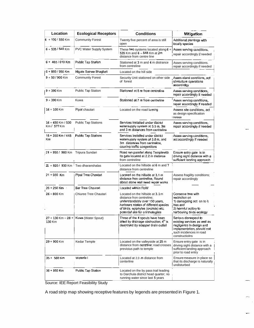
A road strip map showing receptive features by legends are presented in Figure 1.
Location
4 + 100 1 550 Km
Ecological Receptors
Community Forest
---
distance from centre line
Conditions
Twenty five percent of area is still open
6 + 535 I548 Km PVC Water Supply System These two systems located along 6 + 535 Km and 6 + 548 Km at 2m ! repair accordingly if needed
Stationed at 3 m and 4 m distrance 1 Asses serving conditions. i
from centreline / repair accordingly if needed
Located on the hill side
9 + 50 / 900 Km Community Forest Security Unit stationed on other side of forest
9 + 390 Km Public Tap Station
9 + 390 Km Kuwa
16 + 100 Km Pipal chautari Located on the road turning as design specification
16 + 450 Km / 530 Public Tap Stations Km / 577 Km
121 + 950 / 980 Km Tripura Sundari
from centreline --- 21 + 920 / 930 Km Two dharanshalas Located on the hillside at 6 m and 7 1
distance from centreline !
Assess fragility conditions; / repair accordingly
I
1 26 + 800 Km Chiuree Tree Chautari Located on the hillside at 3.1 m
distance fron centreline;
i 1,
27 + 130 Km - 28 + Kuwa (Water Spout) 130 Km
1 such incidences in road
29 + 900 Km Kedar Temple
previoius path to temple
Located at 2.3 m distance from
1 sufficient landing approach I prior to road entry 1
I Ensure measure in place so 1
Located on the valleyside at 25 m distance from centrline; road crosses
centerline I that its discharge is naturally 1 undisturbed i
Located on the by pass trail leading
running water since last 5 years to Darchula district head quarter; no ,
Source: IEE Report Feasibility Study
constructiolns
Ensure entry gate is in 1 driving sight distance with a 1

11. DURING CONSTRUCTION PHASE: ROAD CONSTRUCTION MANAGEMENT
11 .1 LABORFORCE CAMPSITE ESTABLISHMENT I MANAGEMENT / DE-COMMISSIONING
11.1.1 Campsite Establishment: Labor forces are often needed in road upgrading, especially for its civil work4 - drains, structural works (gabion filling in retaining walls, breast wall, toe wall etc) etc.; Day time break for meals, rest etc, and retiring at night needs campsite establishment within proximity of their work sites. I
I
Criteria: I
Environmental management sets out specific criteria for its safeguards to be c&mplied in regard to campsite establishment for labor forces' day break and retiring. Adcordingly, such campsite shall be:
I
One campsite per 3 km length of road stretch, where available Not located at water hole of its down stream consumers Away from potential unstable areas Away from flash flood level Away from any drainage lines (at least 1 Om) In low impact areas where road works induce damage is minimal
Whilst it is desired that campsite to the possible extent are located on the low i+pact sites meeting above criteria, local water availability for the labor force is the key to designating and establishment campsites. I I
During site-specific investigation of this road, prospective sites that are odserved as suitable for campsites are noted indicating its changes (Table 6). I
Table 6: PROSPECTIVE LABORFORCE CAMPSITE ON THE SATGBA'WJH - JHLILAGHAT ROAD I
Source: Site -specific Field Investigation July 17 - 23 '07 I I
No.
1
These sites are mostly of flat land on the valley side, flat ridge on the road bend, abandoned fallow land in some cases etc. Where land of these types are locally available in some sections of road, concerned contractor need to identify suitable one& negotiate with the landowner and reach to an agreement for its hiring. I
I
Chainage
2+100km
Limited spoil accommodable on the left saddle
Existing Site Conditions
Saddle on the left side of road
3
4
5
6
7 - 8
9
1
4 km approx
8 + 000 km
23 + 000 km
24 km approx -- 31 km appro~
32 + 000 km
32 km approx
Both sides of saddle
Left side of road
Valleyside nose on the left of road
Valleyside flat ridge on the left of road
Area of low gradient outside structure
Area of low gradient outside structure I
Flat top on the left; extendable to play ground I I

In the event of suitable ones not available locally, locations specifically indicated by chainage for using prospective sites for the disposal of excess cut / fill materials from earth cuttings may also be used. Contractor need to seek approval for such needs upon familiarity of its configurations and gravity of impact likely to arise upon its usage.
11.1.2 Campsite Management:
Labor force at campsites generates during its usage a substantial quantity of human and other wastes - bio degradable and non degradable - of both pathogenic and non pathogenic ones. These wastes pose a potential source of sanitation conditions as well as environmental hazards to its locality and to downstream settlement.
Contaminating water hole, which traditionally has been used by the down stream consumers, by the labor force through their campsite activities may pose a threat of water borne diseases, especially viral infections - Hepatitis.
Facilities for Labor Force: Toilet
At least two toilets for one campsite of 15 labor forces Installation of removable pan system in each toilet Ventilated Improved Pit Latrines (VIPL)
VIPL type has distinct advantage over conventional soak pit one as being a dry system of latrine, requiring no flushing plus can be removed when no longer it need and installed at its need over and again.
Safety Measures to Laborfoce Involved in Risk Prone Works - Bitumen, Rocks Extractions: Laborforce deployed to construction works along fractured rock site or quarry extractions are prone to rock fall injury especially of head. They are also prone to serious hand and eye ipjure during bituminous works undertaken on road stretch. They need to put on safety gadgets - goggles, glove, boots etc during road surface sealing works especially bitumen handling as well as boots, helmets, gloves etc during works on rock site.
Enerav for the Cooking of the Labor Force: Kerosene - although desirable, it possibly can not be met in sustained supply in view of supply uncertainties, market shortages, price escalations etc Firewood - best and possible option at localities where community forest management system exists; may need to negotiate with the local managing groups for their willingness to its supply upon set out term and conditions, and reach out to an agreement accordingly. Private forest - another source for firewood supplies under similar agreement reached with the owners. Supplies from other sources without a standard agreement should be entertained, primarily to discourage illicit trade within road stretch of works in progress.
Medical Facilities for the Labor Force: Mandatory availability of first aid kit (bandage, medicated tapes, antiseptic solutions, antiseptic cream, cotton wool, paracetamol, benzene, analgesics etc) at each campsite
, Mandatory availability of basic medicines for diseases - diarrhea, amoeba dysentery, pain relief etc
Safe Disposal of Solid Wastes: Improper handlings and disposal of solid wastes generated by labor force at their campsite would results in environmental degradation as well as prompts sanitation

degradations - distractive campsite, polluted water supply, persistent odors, incidences of viral diseases etc.
Remedial Measures: Designate separate areas for solid waste disposal - bio degradable and non degradable one Facilitate recycling of non biodegradable or else its safe disposal
Upon establishment of camps for laborforce, suitable sites for solid wastes - biodegradable and non degradable one - can be identified, designate for its us4. As and where, facility for recycling of non biodegradble does not exist and cannot be aFnged, it can be safely disposed on to deep pits of low valued land. I I
Contractor's Obliaations: I I
Sustained supply of safe drinking water to labor force at their campsites ~ Given river I stream - supply source, it should be safely chlorinated prior to its distribution to the laborforce. Supply and mandatory use of safety gadgets - gloves, goggles, boots, hats e injury prone works
Include in Contract Document:
Contractor's obligations need to be addressed in Bid Document prior to its bid cell
11 .I .3 Campsite De-commissioning: I I I
All camp sites used by labor force need to be de-commissioned and safely clo of environmental hazards to its locality as well as downstream settlements. can not simply de-commission and abandoned these sites at his discretion obtain a 'letter of satisfaction' from supervising consultant.
11.2.1 Campsite Establishment: I I
Road upgrading needs a variety of mechanical equipments (pneumatic roller, aggregate spreader, bitumen spreader, vacuum sucker etc), vehicles (both heavy and ligh ones) etc for its construction works according to the work schedule. These equipment , vehicles often need repairs, maintenance etc.
4 I
As this road was open up to Earthen Fair Weather Standard, all major orks were apparently undertaken with camps sited for the laborforce at locations of pr 9 ximity, not requiring large areas for heavy equipments repairs, maintenance works etc s in road upgrading. Large areas suitable for Contractor's camps can be hired with the I cal people upon negotiation and two party agreeement.
t ~ I I
Criteria: I
Environmental management sets out specific criteria for its safeguards to be domplied in regard to contractor's campsite establishment. Accordingly, such campsite shall be:
Flat and large enough to accommodate all the units - office complex, maintenance unit etc I
Not located at water hole of down stream consumers Away from potential unstable areas Away from flash flood level Away from any drainage lines (at least 1 Om) In low impact areas where road works induce damage is minimal
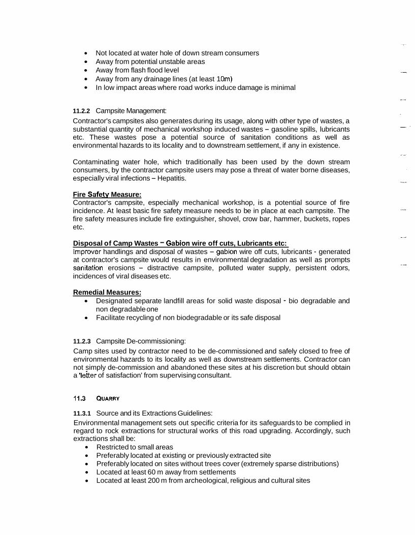
11.2.2 Campsite Management: Contractor's campsites also generates during its usage, along with other type of wastes, a substantial quantity of mechanical workshop induced wastes - gasoline spills, lubricants etc. These wastes pose a potential source of sanitation conditions as well as environmental hazards to its locality and to downstream settlement, if any in existence.
Contaminating water hole, which traditionally has been used by the down stream consumers, by the contractor campsite users may pose a threat of water borne diseases, especially viral infections - Hepatitis.
Fire Safetv Measure: Contractor's campsite, especially mechanical workshop, is a potential source of fire incidence. At least basic fire safety measure needs to be in place at each campsite. The fire safety measures include fire extinguisher, shovel, crow bar, hammer, buckets, ropes etc.
Disposal of Camp Wastes - Gabion wire off cuts, Lubricants etc: lrr~prover handlings and disposal of wastes - gabion wire off cuts, lubricants - generated at contractor's campsite would results in environmental degradation as well as prompts sanitation erosions - distractive campsite, polluted water supply, persistent odors, incidences of viral diseases etc.
Remedial Measures: Designated separate landfill areas for solid waste disposal - bio degradable and non degradable one Facilitate recycling of non biodegradable or its safe disposal
11.2.3 Campsite De-commissioning: Camp sites used by contractor need to be de-commissioned and safely closed to free of environmental hazards to its locality as well as downstream settlements. Contractor can not simply de-commission and abandoned these sites at his discretion but should obtain a 'letter of satisfaction' from supervising consultant.
11.3.1 Source and its Extractions Guidelines: Environmental management sets out specific criteria for its safeguards to be complied in regard to rock extractions for structural works of this road upgrading. Accordingly, such extractions shall be:
Restricted to small areas Preferably located at existing or previously extracted site Preferably located on sites without trees cover (extremely sparse distributions) Located at least 60 m away from settlements Located at least 200 m from archeological, religious and cultural sites

11.3.2 Potential Rock Sources:
Civil works - dry 1 gabion walls, side drains, cross drains etc - of this road upgrading may require a substantial quantity of hard rocks. The potential source of quarry - h a d rock, burrow pits - is outlined in Table 7 I
I
Table 7: PROSPECTIVE QUARRY - ROCK AND BURROW PIT - ON THF SATBANJH JHULAGHAT ROAD I
I
1 35 km approx 1 Rock I Hard rock type on the hillside of the road Source: Site-specific Field Investigation July 17 - 23 '07 ~ 11.3.3 Potential Burrow pits Sources I
I
Gravel surface works - sub base, base courses etc - of this road upgrading m$y require a substantial quantity of burrow pits rocks. The potential source of quarry - hard rock, burrow pits - is outlined in Table 7.
I ~
11.3.4 Vigilance on the Conditions of Extractions: I
Strict vigilance need to be in place during rock extractions at the quarry sourcb. It also needs to ensure that I
I
No rock materials littered on the valley side arable land I I
No condition is created inducing spill over of impoverished materia~ls by the discharge during wet season over the arable land on the valley side ~ No rock materials causing disturbance to public services, utilities etc ~
I I
11.3.5 Closure upon its Non-extractions: I
All quarry source supplying rocks for the civil works of this road upgrading need to be safely closed to agreed conditions upon its extractions no longer required. /.lo quarry source shall be abandoned at contractor's discretion but has to receive Resident Engineer's a 'letter of satisfactory closure'.
I I
11.4 BURROW PITS I I
Upon achievement of road width formation through embankment filling, suitable materials of pits - gravel, sand and other aggregates - needs to be laid over these fortinations at

varying depth of particular specifications with specified thickness in order to gain standard load bearing strength for vehicular traffic.
11.4.1 Source and its Extractions:
Environmental management sets out specific criteria for its safeguards to be complied in regard to borrow pits extractions and for its laying-over road width formation. Accordingly, such extractions shall be:
Restricted to small areas Preferably located at existing or previously extracted site Preferably located on sites without trees cover (extremely sparse distributions) Located at least 60 m away from settlements Located at least 200 m from archeological, religious and cultural sites
11.4.2 Vigilance on the Conditions of Extractions:
Strict vigilance need to be in place during burrow pits extractions at its quarry source. It also needs to ensure that
No pit'materials littered on the valley side arable land No condition is created inducing spill over of impoverished materials by the discharge during wet season over the arable land on the valley side No rampant pits extractions cause disturbance to public services, utilities etc
11.4.3 Closure upon its Non-extractions:
All pits source supplying sub-grade, sub-base, base-course etc materials need to be safely closed to agreed conditions upon its extractions no longer required. No pit source shall be abandoned at contractor's discretion but has to receive Resident Engineer's a 'letter of satisfactory closure'.
11.5 STOCKPILING
Road upgrading needs a variety of construction materials - top soil for enriching impoverished soil in cut I fill batter, sand for civil works, pit materials for laying over road formations. These materials need to be stockpiled at location of minimal lead and free of environmental hazards.
Criteria: Environmental management sets out specific criteria for its safeguards to be complied in - regard to stockpiling - topsoil, pit matirials for laying over the ioad formations -' of this road upgrading. Accordingly, such stockpiling shall be executed:
At least 10 m away from drainage lines On land with less than 10 degree slope On sites devoid of vegetations -trees, shrub Not above house or other civil structures
11.5.1 Top soil stockpiling: Cut I fill batter is in general of impoverished soil type, which is devoid of plant growing nutrients. Top soil, which is rich in humus content and nutrient, is a valuable replenishing supplement to enrich impoverished soil of batter slopes, and help plants strike roots easily and grow subsequently.

Whilst road upgrading generates a relatively lesser quantity of top soil than in new road opening, it still is valuable materials for rehabilitating batter slopes, and hence is worth collecting, stockpiling where it is available and stockpiled accordingly for its ne~ed in the future.
11.5.2 Sand Stockpiling: I
Large quantity of sand may be needed for civil works as well as for road sealing purposes. These materials hauled from distant sources needs to be stored at safe locations- well away from road formation width, not risk prone to peripheral Idcations - prior to its usage according to the work type. I ,
11.5.3 Pit Materials Stockpiling: I I
A huge quantity of pit materials, which needs also to be hauled from distant sources, obviously is required for laying over as sub - grade, sub-base and base course on road width formation. These materials need to be stockpiled at safe locations -well ?way from road formation width, not risk prone to peripheral locations etc- so that its quality is maintained and meet the standard of specifications. Care need to be taken at these locations so that no deleterious materials - plant leaves 1 twigs 1 branclhes, non- degradable materials, clay soil etc - impair such materials.
11.6.1 Origin of Excess Cut I Fill Materials: I I
Earth cutting of proposed road upgrading will generate a varying quantity - depending on the need to achieve design specifications at a particular road section - of exce$s cut 1 fill materials, which are mostly originate: I
I
From back cutting of hill slopes, especially on those sections high height? I slopes. mainly at road bends At sites where by design specification, box cut widening is the need ~ At sites where extra excavation of the existing road sections is required o achieve grade of its specifications t From cutting of existirlg batters on the hill slopes
11.6.2 Prohibit Disposal of Excess Cut I Fill Materials on Unsafe Locations: Excess cut 1 fill materials shall on no account be allowed to dispose it but pro ibit at the following types of sites h
Whilst some proportion of earth materials generated by its cutting can be ubed as fill materials in retaining wall as well as in some of the road sections as and wherd required, especially to achieve road grade, a substantial proportion still may remain as edcess cut I
Fresh but just naturally begin to colonize, stabilize or stabilized unstable slopes Fresh but naturally being to stabilize or stabilized unstable slopes I
On natural water course posing a threat of or causing choking in its flowas well as in its course change I
I
Side cast over the edge of the excavations, fresh embankments I I
Side cast immediately above potentially valued arable land I
Side cast above public utilities and existing services -water supply linei, irrigation canal systems, valley side trails etc I
Side cast above local settlements' physical structures, especially house ~
fill materials, which need to be disposed to safe site without posing or causing a environmental degradation thereafter - both local and regional.
source of

11.6.3 Restrict Disposal of Excess Cut I Fill Materials to Designated Spots Only:
Disposal of excess cut / fill materials on to safe site without its environmental degradation is of prime concern, and proposed upgrading works must attempt to ensuring minimal possible environmental degradations, damages through proper and effective handlings and disposed on to safe sites only.
Excess cut / fill materials generated during road upgrading works need to be disposed to following types of site only
Flat low lying plains Flood plains without stretching over to main course Site requiring land fills, especially local play ground, community ground etc Site requiring value adding land fills, especially reclaiming land for building constructions Broad flat land on the ridge Fresh and swallow rill, gullies spread over large areas Depressions spread over large areas
Safe locations as outlined above are identified during July 18 - 22, '07 road's site-specific -- identifications, and presented by Chainage with suitable treatment of disposed spots (Table 8)
Source: Site - specific Field Investigation July 17 - 23 '07 --
Table 8: PROSPECTIVE SPOIL DISPOSAL SITES AND TYPE OF ITS 'TREATMENT IN ROAD UPGRAGING WORKS OF SATBANJH - JHULAGHAT ROAD
Chainage
1 + 100 km
1 + 300 km
2 + 100 km
+ 000 km
4 + km approx
8 + 000 km
23 + 000 km
24 km +
31 km +
32 + 000 km
32 km +
Potential Effect Upon Spoil Disposal
Minimal effect on the vegetation; no further risks
Minimal effect on the vegetation; no further risks
Minimal effect on the surroundings
Minimal effect on the surroundings
Low damage on the surroundings
Low damage on the surroundings
Low damaging effect on the surroundings
LOW damaging effect on the surroundings
Limited or no damage if spoil disposal well supervised
Limited or no damage if spoil disposal well supervised
Limited or no damage if spo~l disposal well supervised
Existing Site Conditions Alder trees covered valle~slde kholsi
Alder trees covered kho'si
Saddle on the left side of road
Limited spoil accornmodatable on the left saddle
Both sides of saddle
Left side of road
Valleyside nose on the left of road Valleyside flat ridge on the left of road
Area of low gradient outside structure
Area of low gradient outside structure
Flat top on the left; extendable to play ground
Suggested Type of Treatment
No need of specific treatment
No need of specific treatment
Need to spread spoil over large so that its height is low
Need to spread spoil carefully over large area so that its height is low
Need to spread spoil carefully over large area So that its height is low
Need to spread spoil carefully over large area so that its height is low
Need to spread spoil carefully over large area so that its height is low
Spoil needs to be disposed under control over large area so that its height is low
Spoil disposal activities needs to be well supervised and controlled
Spoil disposal activities needs to be well supervised and controlled
Spoil disposal activities needs to be well supervised and controlled with compactions

11.7 REINSTATEMENT OF EXISTING PUBLIC UTILITIES AND SERVICES
Public utilities and existing services, which get interrupted or likely to be interrupted by road upgradings need to be reinstated, needs to be reinstated with a provisional measure in place during construction works in progress ensuring its services not interrupted, and with permanent measure affected within agreed deadline with stakeholder.
'These utilities and existing services observed during site-specific investigation4 that are likely to be disrupted and or affected during upgrading works, are presented by cbainages along with agreed mitigation measures and correction dead line (Table 9).
11.7.1 Disruption in Public Utilities I Services: i Existing public utilities as well as local services, especially of water supply lines, irrigation canal systems, local trails, electric transmission line, telephone productive arable land with impoverished materials etc often disrupted or road constructions in the past, and remained its un-operational until community or contractor (upon persistent persuasion by the mended it.
11.7.2 Embedded Poly pipe for Local Water Supply: I ~
Poly pipes - supply line of drinking water - are at places embedded into th'e ground across road width. These pipes may be crushed during the operation of roller machine,, thereby interrupting its supplies. I
i I
11.7.3 Reinstatement of Public Utilities I Services: Public utilities and existing services need to be reinstated -with a provisional easure in place during construction ensuring services not interrupted, and with permanen measure affected as agreed with stakeholder.
"i I I 11.7.4 Relocation of Transmission I Distribution Line: I
Electric transmission line, telephone distribution line etc are common ibcidences encountered as it physically stationed in the middle of road width formalion upon upgrading road to its design specifications. I I
Table 9: REINSTATEMENT OF EXISTING PUBLIC UTILITIES I ~ERVICES DURING ROAD UPGRADING CONTRACTS AND UPON ITS COMPLETIONS1
g Service
I 4 km +
Site Conditions i Road section of alignment crosses the supply line
Road Of
alignment
3 + 000 krn
Water supply line (112" diarn polypipe)
Water supply line
Rural trail
supplies interrupted by cdrnmencing sub
upgrading works and afterwards I I
Stone Mortar Stepping with 1 I ~t time peripheral
Corrections Need Replaced with GI pipe to avert risk of pipe crushing and supplies interrupted by upgrading works and afterwards Replaced with GI pipe to avert risk of pipe crushing and
3krn+
I
Cbrrection Dead 1 , Line
o erlay - gaSe or to
(112" diam polypipe) crosses the 1 supp~y line
Trail on the right of road
m safe sight to road 6 PCC Mortar Matching Site Conditions
ddain links or civil w ~ r k s to be ccpmpleted

Existing Type of Site Conditions
I
5 + 000 Trail on the right - Rural trail
Pole Dossiblv lie
4 km +
within road width
Distribution Pole
Rural trail
Trail on the left of road (switchback)
6 km +
Trail on the left of road (switch back)
7 km +
7 km + Rural trail 1 Road section of
Rural trail Trail on the right of road
Rural trail Trail on the left of road
22km Approx
I Correction ~ead
27 km
30 km +
Water supply line (1" diam GI pipe)
m safe sight to rda'd or PCC drain lines or civil Mortar Matchinn Site I works to be
Corrections Need
alignment crosses the supply line
Rural trail
Water supply line (112" diam polypipe)
- Conditions 1 completed Stone Mortar Stepping with 1 I At time peripheral
Line
Trail on the hillside
Road section of alignment crosses the
m safe sight to road 07 PCC drain lines or civil Mortar Matchina Site 1 works to be
Stone Mortar Stepping with 1 I At time ~ e r i ~ h e r a l
1 supply line
Relocate the distribution pole well away from road width drain lines or civil
formation works to be
m safe sight to road or PCC drain lines or civil Mortar Matching Site I works to be
Conditions I completed Stone Mortar Stepping with 1 I At time peripheral m safe sight to road or PCC drain lines or civil lblortar Matching Site works to be Conditions completed
Stone Mortar Stepping with 1 At time peripheral m safe sight to road or PCC drain lines or civil Mortar Matching Site works to be Conditions Replaced with GI pipe to avert I risk of pipe crushing and supplies interrupted by upgrading works and afterwards
completed
Prior to commencing sub - base course overlay
Source: Site -specific Investigation July 17 -23 '07 1 1
12. DURING CONSTRUCTION PHASE: ROAD CORRIDOR ENVIRONMENTAL IMPROVEMENTS
12.1 ROAD SIDE SLIPS STABILIZATIONS
Hillside slips have been commonly observed environmental issue of this road upgradings. These slips at places may not only disrupt road serviceability but also choke side drains elsewhere.
The incidence of failures of these slips at places is of recurrent nature, which is largely attributing to a combination of extremely loose soil conditions, devoid of hill vegetations, and its steep slope. The rock extractions as a supply source for structural works have aggravated the situations.

Hill side slips of critical conditions, which were observed during site - specific investigations of this road, are presented it later for environmental improve mental improvement works, especially bio-engineering.
12.1.1 Objectives ,
Following environmental improvement objectives aimed to be achieved thiough the implementation of the bio-engineering techniques as outlined below: I
Stabilize cut and fill slopes. I I
Reduce surface erosion. I I
Reinforce the civil structures. I
Develop better water management for the protection of road pavement and structures. I
I
Reduce the maintenance cost of the road. I
Improve the aesthetic appearance of road corridor. I
Maintain the ecological balance of the road surrounding. I
12.1.2 Strategy for Bio-engineering Works a Success I ,
Five strategies are identified and established as pre-requisite for bio-engineeridg works a success: I
I
Ensure sites requiring bio-engineering works critically assessed with regard to its site conditions - physiographic type, distribution of rock, soil over the area, soil type and moisture availability etc - and identified resource limitations fod plantings. This aims help identify limiting conditions against which appropriate measure is in place; I
Ensure practical remedial measure is identified, suggested and implemented accordingly; ' Ensure plant production schedule is worked out realistically and tor/-ectly, and executed plants producing nursery activities in such a way that plan s are well rooted, sufficiently hardened, appropriately sized (proportionate root sh ot ratio) at the time of its plantings. This aims to achieve optimal stocking of lantings - growing well with its root struck on to site successfully;
1 Ensure site requiring bio- engineering treatment available to concernid workers prior to pre monsoon so that planting works can be commenced uring site condition full of moisture, which eases plant strike its roots and grow s bstantially
pre-monsoon and grow in the follow monsoon; and
I in the following monsoon. This aims plant struck its root as soon as pssible in
Practice planting local species - mostly of grass and shrub species and some short sized locally preferred trees - preferred to general ones on the sit 1 s requiring its roots' quicker struck and coverage. This is possible with only those species that has been naturally selected and striving for long within local con itions and available resources - moisture, soil depth, nutrients etc.
d I
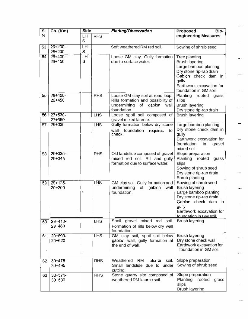
12.1.3 Findings I observations and Proposed Bio- engineering Measures I I
Site assessments in regard to slope conditions along the Satbanjh - ~hu la~hak alignment were made, and accordingly its findings I observations citing its bed compositic/n including soil content along with prospective mitigation measures have also been pdoposed as presented in Table 10. I
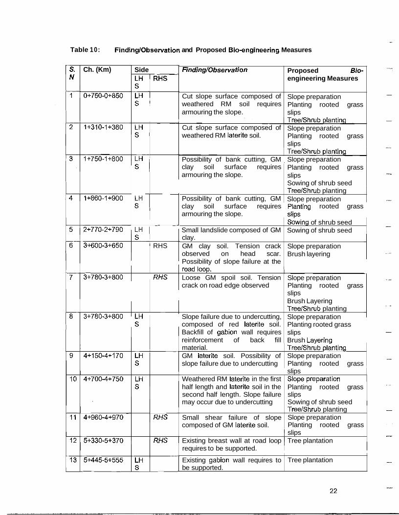
Table 10: FindinglObservation and Proposed Bio-engineering Measures
Ch. (Km) Side LH RHS C
RHS
p Possibility of bank cutting, GM I Slope preparation
Finding/Observa tion
Cut slope surface composed of weathered RM soil requires armouring the slope. Tree/Shrubglantlng Cut slope surface composed of weathered RM laterite soil.
Proposed Bio- engineering Measures
Slope preparation Planting rooted grass slips
Slope preparation Planting rooted grass slips
clay soil surface requires armouring the slope.
clay soil surface requires rooted grass armouring the slope.
Planting rooted grass slips Sowing of shrub seed
Possibility of bank cutting, GM ~ r e e l ~ h r u b planting Slope preparation
Small landslide composed of GM sowing of shrub seed Sowing of shrub seed
clay. GM clay soil. Tension crack observed on head scar. Possibility of slope failure at the p Loose GM spoil soil. Tension crack on road edge observed
Slope failure due to undercutting, composed of red laterite soil. Backfill of gabion wall requires reinforcement of back fill
I slips Weathered RM laterite in the first i S l o ~ e ~ re~ara t i on
Slope preparation Brush layering
Slope preparation Planting rooted grass slips Brush Layering TreeIShrub planting Slope preparation Planting rooted grass slips Brush Laverincl
material. GM laterite soil. Possibility of slope failure due to undercutting
~ r e e l ~ h r u b &nthg Slope preparation Planting rooted grass ,
half length and laterite soil in the second half length. Slope failure may occur due to undercutting
1 slips Existing breast wall at road loop Tree plantation
, . , Planting rooted grass slips Sowing of shrub seed 1
Small shear failure of slope composed of GM laterite soil.
requires to be supported. 1 I
TreeIShrub planting Slope preparation Planting rooted grass
Existing gabion wall requires to be supported.
Tree plantation

I I I 1 undercutting. ( slips 1
Proposed Bio- engineering Measures
Slope preparation Planting rooted grass
supported and anchor near Road I I
loop. I
Small landslide composed of GM Slope breparation clay soil may damage the upland plantidg rooted grass
Finding/Observation
Red laterite soil surface. Possibility of slope failure due to
15
1 1 1 agricultural land. 1 slips ~ I
S. N
14
Small landslide composed of
Ch. (Km)
5+505-5+525
Side
5+645-5+715
gravel mixed clay soil may Plantiqg rooted grass 1 damage the upland agricultural slips
LH S LH S
I 1 land. ) Shrub (planting I
p-
18 7+350-7+400 0
RHS
LH
- I - 1 TreeISbrub planting Existing wall requires to be ( Treepl)antation
19
20
8+210-8+260
I 21
22
23
24
25
LH S
1
I
8+360-8+370
8+450-8+480
8+480-8+500
8+600-8+630
I S i ( may fail due to undercutting.
I I s I . . .
( surface requires armouring and planding rooted 4
1 8+280-8+330
8+700-8+730 I
1 gravel mixed clay.
coarse GM clay soil.
Weathered RM red laterite soil. slope failure may occur due to
LH S
LH S
LH S
LH S
LH S
h 0 - 8 + 7 2 0 1 ( RHS 1 Loose spoil soil composed of ) ~ r u s $ layering , -
Sowing of shrub seed Broad(zsting grass seeds 1 Slope preparation SowinD of shrub seed
undercutting Weathered RM red laterite soil. slope failure may occur due to
LH 1
27 1 8+735-8+750 1 LH 1 1 GM laterite soil. Cut slope 1 SIOR$ preparation
I I
slopelpreparation Sowinb of shrub seed
I GM red laterite soil. Slope may fail due to undercutting
Red laterite soil surface. Cut slope may fail due to undercutting Small slope failure due to undercutting. Weathered RM laterite soil
- I ~ree//Shrub planting Weathered RM clay soil. Slope / ~owit/tg of shrub seed
Red laterite cut surface. Slope due to undercutting.
!' slope^ preparation Brush layering Sowidg of shrub seed road casting grass seed4 Slopel preparation plantikg rooted grass slips Slope preparation Planting rooted grass slips 1

S. N
28
29
30
31
Ch. (Km)
32
33
8+750-8+800
9+060-9+090
9+950-9+970
10+420-
34
35
I I 10+860- 10+890
10+860- 10+890
36
Side
LH S
LH S
slope failure due to surface water Planting rooted grass and undercutting. I slim
12+300- 12+330
12+340- 12+360
coarse GM clay. Slope may fail I due to undercutting and surface water.
Finding/Observation
bacMill of breast wall requires
LH S
LH S
12+500- ( LH Brush layering Sowing of shrub seed Broadcasting grass
Weathered RM soil at head scar- GM clay above the existing breast wall. Rill formation due to surface water.
Proposed Bio- engineering Measures
slips
RHS
RHS
RHS
L H S
L H S
( undercutting. 1 Stone quarry site composed of Slope preparation
Slope preparation Brush layering Sowing of shrub seed Broadcasting grass seeds
38
RHS
I
39
I 1 16+570 I I formation due to discharge from 1 Large bamboo plantation pipe culvert. Gully control is TreeIShrub planting ~
reinforcement. GM clay soil. Landslip may occur due to undercutting and surface
1 water. Weathered RM soil surface. Possibility of slope failure due to
1 undercutting. Stone quarry site composed of GM laterite soil.
GM clay soil surface. Possible
at the road edge. Coarse GM clay soil. Slope may fail due to surface water and
I undercutting. Coarse GM clay soil. Slope may fail due to surface water and
14+160-
I reinforcement.
Brush Layering Brush layering Sowing of shrub seed
Sowing of shrub seed
Sowing of shrub seed Broadcasting grass seeds Slope preparation
-
Weathered RM red soil. Landslide may occur due to undercutting.
---- Loose spoil soil composed of red
Sowing of shrub seed Broadcasting grass seeds Sowing of shrub seed
14+190
15+190- 15+200
40 1 16+550-
~ r b e l ~ h r u b planting Slope preparation Planting rooted grass slips Brush layering Brush layering
RHS Loose GM clay soil near road
1 RHS ( GM red laterite soil. Gully I Brush layering
41
laterite. Tension crack observed TreeIShrub planting
Dry stone rip-rap drain Brush layering
RHS
16+550- 16+560
loop requires reinforcement.
Weathered RM soil. Backfill of gabion wall requires
Brush layering Sowing of shrub seed
LH S
necessary. GM laterite soil. Landslide due to surface water may threat the
Slope preparation Planting rooted grass

Proposed Bio- engineering Measures
slips Shrub $lanting Slope preparation
1 16+670
Finding/Observa tion
building above.
Spoil material composed of GM 1 clay. It requires reinforcement. I Brush Ibyering
I I 16+840 I S I I laterite soil has damaged the upland agriculture land. Backfill
I I I I ( undercutting.
S. N
42
43 1 16+830- I L H I I Small landslide composed of red / Slope dreparation plantin+ rooted grass slips 1
I
44
Ch. (Km)
16+64.0-
Side LH S
16+900- 16+920
45 ( 17+830-
RHS
RHS
formation due to discharge from culvert. Tension crack on road edge observed.
LH S
RHS Plantin rooted grass slips I Brush layering Lar'ge bamboo plantation Dry st ne rip-rap drain Gabio 4 check dam EarthNork excavation for founddtion in GM soil.
Small landslide composed of 17+875 gravel mixed red laterite due to
undercutting.
-
Loose GM clay soil below gabion Tree planting wall. Rill erosion and possibility Brush layering of undermining of gabion wall Dry stone rip-rap drain foundation. ~ ~
Shrub planting Slope preparation Plantilg rooted grass slips ,
1 Shrubplanting
LH 1 1 I-oose GM clay spoil soil. I Brushlayering
) of gabion wall requires reinforcement. Old landslide with gravel mix clay soil may chock the culvert due to
Loose spoil laterite soil. Gully
1 47 21+520-
S ( Possibility of road edge erosion. I I
LH Loose GM clay soil. Required to Brushlayering S trap materials moving down the 1 I
I
Shrub planting Brush Ibyering Slope $reparation Plantinb rooted grass
Brush l~ayering Slope fireparation
I RHS 1 Weathered rock mixed soil. ) sowink of shrub seed
road and to reinforce the soil, I
GM loose soil. Gully formation ~ rush i layering due to culvert discharge. Gully ~abioln -check dam in control works are necessary. I gully ~ 1 Earthwork excavation for
Earthyork excavation for foundbtion in GM soil.
RHS
LHS
Loose GM clay. Gully formation due to surface water.
S. N
53
Loose GM clay soil at road loop. Rills formation and possibility of undermining of gabion wall foundation. Loose spoil soil composed of
Ch. (Km)
26+200-
Side
1 I 1 ( wall- foundation requires to
Finding/Observation LH S
1 27+550
-
Tree planting Brush layering Large bamboo planting Dry stone rip-rap drain Gabion check dam in gully Earthwork excavation for foundation in GM soil. Planting rooted grass slips Brush layering Dry stone rip-rap drain Brush layering
Proposed Bio- engineering Measures RHS
1 gravel mixed laterite. Large bamboo planting Dry stone check dam in
Sowing of shrub seed L H
gully Earthwork excavation for foundation in gravel
, Soft weathered RM red soil.
57 1 29+030 I LHS Gully formation below dry stone
mixed red soil. Rill and gully formation due to surface water.
58
GM clay soil. Gully formation and undermining of gabion wall foundation.
Planting rooted grass slips Sowing of shrub seed Dry stone rip-rap drain
29+025-
Shrub planting Sowing of shrub seed Brush layering Large bam boo planting Dry stone rip-rap drain Gabion check dam in gully Earthwork excavation for
RHS
1 29+460 I 1 I Formation of rills below dry wall / 60
Old landslide composed of gravel
gabion wall, gully formation at the end of wall.
mixed soil. Slope preparation
29+410-
LHS Brush layering Dry stone check wall Earthwork excavation for foundation in GM soil.
foundation. GM clay soil, spoil soil below
LHS 1 foundation in GM soil. ---
Spoil gravel mixed red soil. ) Brush layering
62 1 63
30+475- 30+495
30+570- 30+590
RHS
RHS
Weathered RM laterite soil. Small landslide due to under
Slope preparation Sowing of shrub seed
cutting. Stone quarry site composed of weathered RM laterite soil.
Slope preparation Planting rooted grass slips Brush layering

S. Ch. (Km) Side Finding/Observation N LH 1 RHS
I 1 1 30+950 ( fail due to undercutting and 1 I I
Proposed Bio- enginepring Measures
I
64 30+850- RHS Coarse GM clay soil. Slope may
RHS
RHS
I
Shrub $lanting Sowing of shrub seed
surface water. Small landslide composed of GM laterite soil. Slope may fail due to under cutting. Surface armouring is necessary. Small landslide composed of GM laterite. Backfill of breast wall requires reinforcement and surface armouring.
I I
Slope treparation Planting rooted grass s l i ~ s ~ shrub b~anting Slope breparation Plantinb ' rooted grass slips ~ Brush l~ayering Sowind of shrub seed
1 New landslide due to
1 Shrub planting GM clay soil. Toe of gabion wall I Tree planting
~hrubb lan t in~ Slope breparation -
undercutting. Red laterite soil.
requires support and anchor the slope.
~ ~ a n t i n b rooted grass slips ~ Brush layering
69
70
1 32+450 1s I ( support and anchor below I I
I I
32+350- 32+380
32+350-
71
formation due to surface water. Dry st ne rip-rap drain Dry st ne check dam Earth ork excavation for I E
1 32+380
L H 32+400-
72
L H
RHS
RHS
S slope is necessary. Existing retaining wall requires
32+500-
73 dry wall. ~ o e protection is ~ ~ r t h ork excavation for necessary. 1 found!on in gravel
mixed soil. BM laterite soil. Slope may fail Sowin~g of shrub seed due to undercuttin . BM laterite soil. S l o ~ e mav fail Sowinla of shrub seed
Reinforcement of embankment
RHS
Tree dlanting
RHS
32+550
1 33+280 I S 1 / requires armouring and support. I Plantihg rooted grass I
Weathered RM clay soil. The slope may fail due to undercutting. Loose GM clay soil.
76
77
78
foundation. BM red laterite soil. Gully
LH
Sowing
I I
sowine of shrub seed
32+680 32+830- 32+970 33+130- 33+240 --- 33+260-
of shrub seed
I
Brushayering
BM soil. Gully formation below
- due to undercutting.
RHS BM laterite soil. Slope may fail ~owi r /g of shrub seed due to undercutting. I I
LH Possibility of shoulder edge brush^ layering S LH GM red laterite soil at road loop Slope preparation
foundhtion in GM soil. Dry stbne check dam
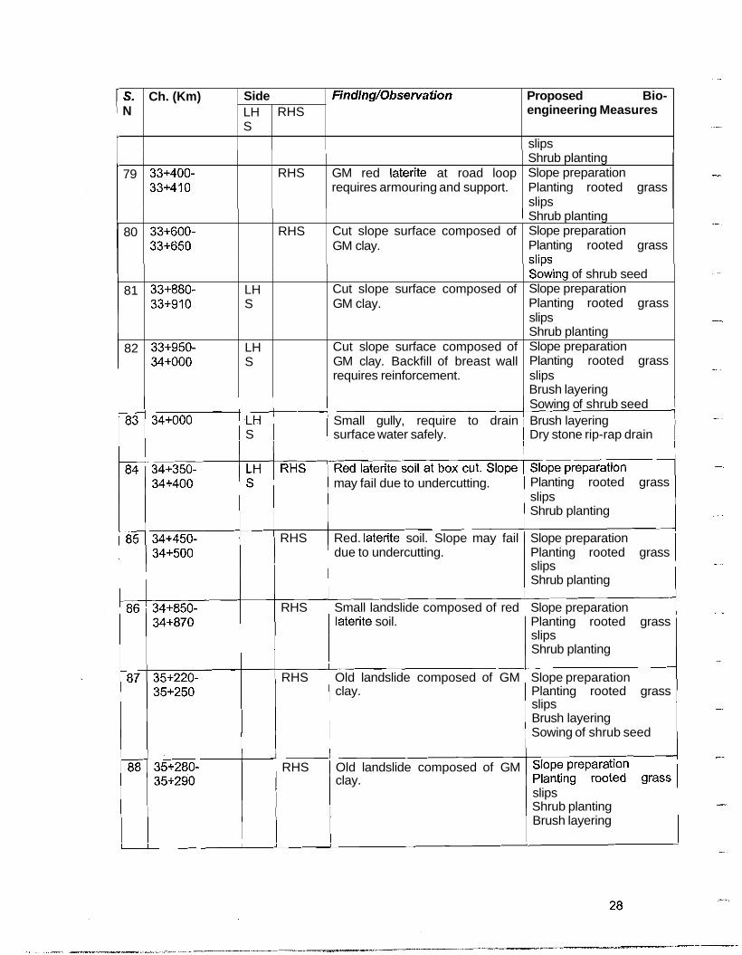
Proposed Bio- engineering Measures
slips
79
S. N
80
Sowing of shrub seed 34+000 .LH Small gully, require to drain Brush layering
S surface water safely. Dry stone rip-rap drain
Ch. (Km)
33+400- 33+410
81
82
may fail due to undercutting.
Finding/Observation Side
33+600- 33+650
Planting rooted grass slips Shrub planting
LH S
RHS
33+880- 33+910
33+950- 34+000
I
RHS Red. laterite soil. Slope may fail Slope preparation due to undercutting. Planting rooted grass
slips Shrub planting
RHS
RHS
RHS Small landslide composed of red Slope preparation laterite soil. Planting rooted grass
slips Shrub planting
GM red laterite at road loop requires armouring and support.
LH S
LH S
RHS Old landslide composed of GM Slope preparation clay. Planting rooted grass
slips Brush layering Sowing of shrub seed
Shrub planting Slope preparation Planting rooted grass slips
I Shrub planting
I I I
35+280- / RHS 1 Old landslide composed of GM
Cut slope surface composed of GM clay.
Cut slope surface composed of GM clay.
Cut slope surface composed of GM clay. Backfill of breast wall requires reinforcement.
clay.
Slope preparation Planting rooted grass s l i ~ s s k i n g of shrub seed Slope preparation Planting rooted grass slips Shrub planting Slope preparation Planting rooted grass slips Brush layering
slips Shrub planting Brush layering

Proposed Bio- engineering Measures
89
FindingDbservation
90
I I I I I I
Note: (i) GM : Gravel Mixed (ii) BM : Boulder Mixed (iii) RM : Rack Mixed I I
S. N
35+880- 35+905
91
92
12.1.4 Selection Criteria of Plant Species I I
Suitable plant species for the proposed bio-engineering works will be identified and selected based upon the following key points. I ,
Ch. (Km) Side
36+015- 36+115
Prompt root striking
Drought resistant
Rapid growth
Long Living Adapt to the individual site condition.
Substantial root growth
LH S
I I I
36+107
36+750- 36+850
12.1.5 Quantity and Cost Estimate for Bio-engineering Works 1 I
Quantity in regard to proposed mitigation measure for correcting vulnerable slqpes based on its site specific assessments have been worked out according to its spot risk level (Table 11). These quantities in turn have also been translated into cost basbd on rate analysis worked out for each items (Table 12). I ,
RHS
Slope preparation Brush lgyering Sowing; of shrub seed
I
I I
RHS
I
RHS
GM clay soil. Backfill of breast wall requires reinforcement.
RHS
RHS
GM clay soil. Backfill of breast wall requires reinforcement.
Brush lbyering Sowing of shrub seed
Gully formation due to surface water requires to be checked.
slope. BM red laterite soil. Fresh cut
I
Gabion check dam in !3ull~ Earthw rk excavation for founda ion in GM soil. p Slope ereparation Plantinjg rooted grass slips 1
Brush layering 1 Shrub blanting I I
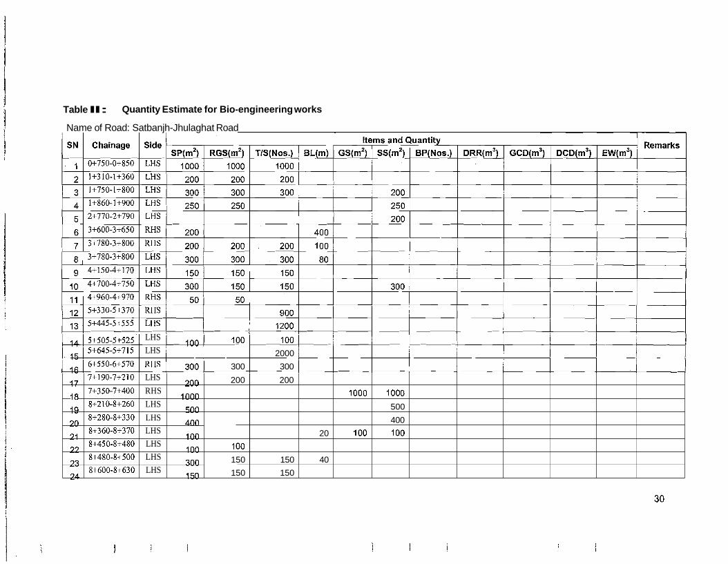
Table I I: Quantity Estimate for Bio-engineering works
Name of Road: Satbanjh-Jhulaghat Road
14 5+505-5+525 100 100 100 LHS
15 5+645-5+715 LHS 2000
16 6+550-6+570 RHS 300 300 300
17
18
19
20
21
22
23
24
7+190-7+210
7+350-7+400
8+210-8+260
8+280-8+330
8+360-8+370
8+450-8+480
8+480-8+500
8+600-8+630
LHS
RHS
LHS
LHS
LHS
LHS
LHS
LHS
200
1000
500
400
100
100
300
150
200
100
150
150
200
150
150
20
40
1000
100
1000
500
400
100 I

e of Road: Satbar
Chainage
~Jhulaghat Road
Sidc
8+700-8+730
8+7 10-8+720
8+735-8+750
8+750-8+800
9+060-9+090
9+950-9+970
10+420- 10+470 10+860- 10+890 10+860- 10+890 12+300- 12+330 12+340- 12+360 12+500- 12+580 14+120- 14+180 14+160- 14+190 15+ 190- 15+200 16+550- 16+570 16+550- - - - - - - - - - 16+560 16+640- 16+670 16+830- 16+840
400 400
150
1200 300 1200 1200
1000 500 1000 1000 6 --
200
20 100
100 4
-- l o o ---m--- - 1 o r - - - - --- - - -. - - - - - - -
~ -_------- ~ ---- ------- ---
300 250
50 50 50 10
LHS -
RHS
LHS -
LHS
LHS
RHS
RHS -
LHS
RHS
LHS
LHS
LHS
LHS
RHS
RHS
RHS
LHS - - - - -
RHS
LHS
Remarks

ie of Road: Satbanjh-Jhulaghat Road
Chainage
16+900- 16+920 17+830- 17+850 17+865- 17+875 21+520- 21+560 22+770- 22+780 23+850- 23+860 24+000- 24+050 24+970- 24+980 25+650
26+200- 26+230 26+400- 26+450 26+400- 26+450 27+530- 27+550 29+030
29+025- 29+045 29+125- 29+200 29+410- 29+460 - 29+600-
Side
LHS
RHS
LHS
RHS
LHS
LHS
LHS
LHS
LHS
LHS
LHS
RHS
LHS
LHS
RHS
LHS
LHS
LHS
Remarks
-
SP(m41 200
300
50
500
-
BLlm) 4 0
200
60
50
100
150
200
150
200
200
150
300
100
R G S ( ~ * )
200
300
50
200
500
T/S(Nos.)
200
300
50
800
200
500
---
-
-
Items and
G S ( m ' )
400
500
500
2000
Quantity BP(Nos.)
10
20
10
50
- -
D R R ( ~ ' )
5
5
I 0
2.5
4.5
7.5
GcD(rn3)
15
15
50
25
30
D C D ( ~ ' )
7
8
E W ( ~ ' )
5
5
13
8
3
10
3

e of Road: Satbanjh-Jhulaghat Road
Remarks Chainage Side
29+620
30+475- RHS 30+495 30+570- RHS 30+590 30+850- RHS 30+950 3 1+230- RHS 3 1+240 32+220- RHS 32+230 32+280- LHS 32+300 32+270- RHS 32+330 --- 32+350- RHS 32+380 32+350- LHS 32+380 32+400- LHS 32+450 - 32+500- RHS 32+580 32+550 LHS
32+600- RHS 32+630 32+650- RHS 32+680 32+830- RHS 32+970 33+130- LHS 33+240 -- 33+260- LHS .
-
sp(m2)
150
Items and Quantity
100
100
100
150
R G S ( ~ ~ )
- -
D C D ( ~ ~ ) G C D ( ~ ~ )
100
100
100
150
G S ( ~ ~ ) T/S(Nos.) E W ( ~ ~ )
400
1500
100
250
1200
400
300 - -- ---
BL(m)
800 ----
-- ----- ~
200
ss(rn2)
150
300
800 --
60
20
40
--
- - - -
200
BP(Nos.) D R R ( ~ ~ )
2.5
----
200 140
15
8
---
---
---
5
3
--

Remarks
Name
SN
79
80
81
82
83
84
85
86
87
88
89
90
91
92
of Road:
Chainage
33+280
33+400- 33+410 33+600- 33+650 33+880- 33+910 33+950- 34+000 34+000
34+350- 34+400 34+450- 34+500 34+850- 34+870 35+220- 35+250 35+280- 35+290 35+880- 35+905 36+0 15- 36+115 36+107
36+750- 36+850
Total
Side
RHS
RHS
LHS
LHS
LHS
LHSI RHS RHS
RHS
RHS
RHS
RHS
RHS
RHS
RHS
quantity
Satbanjh-Jhulaghat Road
E W ( ~ ~ )
7
62
sp(m2)
500
300
400
400
150
150
400
200
250
1500
15650
Gs(rn2)
3900
Quantity BP(Nos.)
94
GcD(rn3)
25
160
Items and
ss(m2)
500
400
400
250
800
16720
D R R ( ~ ~ )
4.5
47.5
DcD(rn3)
38
BL(m)
100
20
200
40
100
200
200
5760
R G S ( ~ ' )
100 -
500
300
400
400
150
150
400
200
1500
10550
TIS(Nos.)
100 -
300
400
150
150
200
1500
14800

Note:SP=Slope preparation, RGS=Planting rooted grass slips, T/S=Tree/Shrub planting, BL=brush layering, GS=Broadcasting grass seeds, SS=sowing of shrub seeds, BP=large bamboo planting, DRR=Dry stone rip-rap drain, GCD=Gabion check dam, DCD=Dry stone check dam, EW=Earth work excavation for foundation.
Name of Road: Satbanjh-Jhulaghat Road
Table 12. Cost Estimate for Bio-engineering Works
Items and Quantity
cification Clause No. 285
~ ~ ---------- ~ - - - - - - - - - - - - - - - - - - - - - - ~
Remarks S P ( ~ ' ) / R G S ( ~ ~ ) / TIS(Nos.) / BL(m) I Gs(m2) /[ E W ( ~ ~ )


12.2 Critical Spots Requiring Urgent Mitigation Action Site assessments in regard to slope conditions along the Satbanjh - ~ h u l a ~ h a t IRoad alignment were made. No critical spots requiring urgent mitigation action at the; time of visit were observed I
I
13. IMPLEMENTATION MECHANISM: I I I
Environmental impacts induced by road upgrading begin to surface up and are dbserved when Contractor's construction activities commences and are taking upgrading with its severity, limits and extent depending on how seriously implications are understood and respected.
Environmental concerns and measure up to its study along with its management need on the site during implementation is well recognized, organized and respected. How ver, this still has to surface up with the Contractor who undertake construction activities wi h a little or no respect to the environment, inflicting tremendous damage on the environm nt. This damage is due to absence of technical skill, know how, control etc, more specific Ily of an environmental expert, which needs to be in place with the Contractor as do or other disciplines. 1 I
14. ITEMS TO PROVISION IN BID DOCUMENT I
14.1 SERVICES OF ENVIRONMENTAL CUM BIO-ENGINEERING EXPERT I
Bid document needs to provision, as a responsible contractor to procure Environmental cum Bio- engineering expert who will be accountable to his representative (supervising consultant) and responsible for Environmental Management Action Plan on the site of this Environmental Expert's job is to work in close contact especially with Environmental upgrading induced implications within conditions of contract and special bio-engineering works in line with Environmental Expert also regularly needs to report on the status, conqitions of environmental safeguards practiced to the employer through its representative. ~
14.2 REINSTATEMENT OF PUBLIC UTILITIES AND SERVICES I I
Rural trails, water supply lines, irrigation canal systems often damaged by the pgrading works and abandoned without respect needs to its reinstatement. q I
Bid Document needs to provision items of PCC or Rock Mortar Type Conditions; cost for this item need to be addressed and incorporated in bid
Bid Documents needs to provision of items 1" or 112" Dia GI Pipe over Ro d Cross Sections; cost for this item need to be addressed and incorporated in bid docum 1 nts
~ Bid Documents needs to provision items of PCC or Dry Rock Lining ~ a t c h i n ~ Site Conditions; cost for this item need to be addressed and incorporated in bid docuhent
Items to provision in Bid Document otherwise not included in other headings ofi contract, are outlined in Table 13. I
Table 13: ENVIRONMENTAL COMPLIANCE RELATED WORK ITEMS A ~ D ITS ESTIMATED COSTS IN ROAD UPGRADING WORKS I


I Environmental Protection Work 1 1 Per Unit 1 I I
Items I Nos. I Cost I Total I Action , I 1 I I Omanize trainino cum workshoo on construction and environmental 1
1 3 Reinstatement of Public Utilities and Sewices I I I I I
Tra~ning cum workshop PS
I I I I
management p&ciples to ont tractor's Fleld Supew~sor, Laborforce Gangleader
I
PS
3.1 Trails (Hillside I Valleyside)
incorporated in bid document
Bid Document needs to provision items of P C or Rock Mortar Type Matching Site Conditons; cost for this item nied to be addresed and
I 1 incorporated in bid document i 1
3.2 Drinking Watersupplies
15. SITE SUPERVISION, MONITORING AND REPORTING I I
The strict supervision of construction activities needs to be in place prior to abd during road upgrading to ensure that: I
I
Works are constructed in accordance with the approved designs and ~ Environmental impacts are fully mitigated with the EMAP I
I
PS
PS
A standard system of site inspections, approvals and reporting shall be undert4ken over the period of road upgrading. I
Bid Documents needs to provision of items 11' or 112" Dia. GI Pipe over Road Cross Sections; cost for this item need to be addresed and incorporated in bld documents I
I I
Bid Documents needs to provision items of PCC or Dry Rock Lining Matchina Site Conditons: cost for this item nked to be addresed and
Monitoring and reporting of environmental management activity prior to and dqring road upgrading shall also be undertaken as outlined in Table 14.
I I
The Supervising Consultant shall undertake the following site inspections, in cdnjunction with the Contractor, where specified to: I
assist in site planning and oversee constructions and its environmental impacts
15.1 PRE-CONSTRUCTION PHASE I I
Two pre-construction inspections of section of alignment shall be undertakgn by the Supervising Consultant and Contractor. I ,
Pre-construction Inspection 1: Shall involve a site review of upgrading worlGs along a stretch of 4 - 6 km of road. It will serve to: I
I
Identify and locate by Chainage site - specific environmental problems I I
Identify and locate by Chainage prospective labor force campsites I , ldentify and locate by Chainage services that needs to be reinstated I
I
ldentify and locate by Chainage prospective excess cut 1 fill materials disposal ~ ldentify and locate by Chainage sources of rock for retaining wall construction ~ Plan the phasing of construction along the alignment avoiding duplication of works and optimization of local resources use. I I


During the inspection, Supervising Consultant and Contractor shall discuss and agree upon issues list above, including the services that need to be reinstated as well as acceptable excess cut / fill disposal sites.
The Supervising Consultant shall, accordingly, document the type and locatidn of all services that need to be temporarily reconnected and reinstated by the ~ontractdr, and a copy of this to the Contractor. I
Pre-construction lnspection 2: Shall occur after the Supervising consultant has surveyed and pegged the crest and toe of cut I fill batter, retaining wall sites, dr;ain lines and the Contractor has pegged all excess cut I fill materials disposal sites, campqites etc.
The Supervising Consultant shall review the sites pegged by the Contractor and approve them for construction where appropriate or request the Contractor to re-peg sites4
Follow-up lnspection - any specific sites that require re-pegging shall be re-i by the Supervising Consultant and the Contractor. The Supervising approve these sites or request the Contractor to re-peg as necessary.
15.2 CONSTRUCTION PHASE I
The Supervising Consultant shall undertake daily, weekly, and monthly superv/sion and inspections of upgrading works during the period of construction and of camcsites as necessary. I
I
Daily Supervision - the Supervising Consultant shall supervise the followihg works under construction each day:
Excavation activities Fill embankment construction Excess cut I fill materials disposal ~
If any activities are not undertaken in accordance with the contract or EMAP c nditions, the Contractor shall be verbally requested by the Supervising Consultant to r ctify the situations.
1 I
Weekly lnspections - the Supervising Consultant shall undertake weekly insp conjunction with the Contractor, of all the works inspected during the daily well as the following work under construction:
Retaining and breast wall construction Drains construction Reinstatement of public utilities and services Quarry 1 burrow pits
If any activities are not undertaken in accordance with the contract or EMAP +nditions, the Supervising Consultant shall document these activities and specify measures in the Weekly Report. The Supervising Consultant shall provide a c Weekly Report to the Contractor within 2 days of the lnspection for action.
All drainage works and drain outlet areas will be inspected after each major s t o h event. I I
Monthly lnspections - the Supervising Consultant shall undertake a monthly Inspection of all sites in use over the preceding month, as well as site activities currently i n progress, at the end of each month in conjunction with the Contractor. I
I I I

If any activities are not undertaken in accordance with the contract or EMAP conditions, the Supervising Consultant shall document these activities and specify corrective measures in the Monthly Report. The Supervising Consultant shall provide a copy of the Monthly Report to the Contractor within 2 days of the Inspection for action.
15.3 PROJECT LEVEL MONITORING I I
Supervising Consultant shall, on behalf of project, undertake its level of moni!oring of road upgradings leading to gravel seal standard. This monitoring will be of tqree tiers nature with: I
I
Daily Supervision - Excavation activities, Fill embankment construction and Excess cut I fill materials disposal ~
Weekly lnspections - Retaining and breast wall construction, Drains constructioh, Reinstatement of public utilities and services and ~ u a r r y I burrow pits ~
Monthly lnspections - inspection of all sites in use over the preceding month, 4s well as site activities currently in progress, at the end of each month in conjunction with the Contractor. 1
15.4 DoR LEVEL MONITORING
DoR shall undertake bi-annual monitoring of upgrading works with specific focus on issues associated with road upgrading, level of contractor's non respect to EMAP, site constraints etc. I


Table 14: MONITORING OF ROAD UPGRADING'S ENVIRONMENTAL MANAGEMENT ACTIVITY
Phase i
Pre - construction
Permits
Environmental Action
Trainina
Responsibility
AIl contractor's technical field staff attend the 'Environmental Management Targeted to Road Construction Practitioners ' Respect to Effective Implementation
and receive accreditation prior to construction commencing of site - specific EMAP Prior to commencing
Contractor construction activities
Consultant As required Suoervisina
Obtain all necessary permits prior to commencing any s r a d i n g works
Provide a copy of all permits to the contractor
Adhere to all terms and conditions
Obtain written permission from private landholders to conduct activities on their land prior to its commencing, and provide copies to Supervising Consultant
Organize and convene the 'Environmental Management Targeted to Road Construction Practitioners' as outlined Table 13 as a part of Capacity Building
I Consultant and Jointly inspect the surveyed works Contractor
Worksite Survey, Pegging Locate, peg out and seek approval from the Supervising and Approval Consultant prior to the commencement of related activities All works constructed as pegged
Performance Indicator
Supervising and approve, if correct, all pegged sites
Schedule
DoR DoR
Contractor
Contractor
DoR, Supervising Consultant
Continue to survey and peg out at least 2000 m of upgrading Supervising ahead of furtherest of construction underway Consultant As required
Constructions
Work Commenced as scheduled
Copies received
No case of conditions infringed
Permission obtained
Training cum Organized
I Locate, peg out and seek approval from the Supervising Laborforce Campsite Established at Consultant for the Laborforce Campsite Establishment Contractor Designated Location only I /
Prior to commencing construction activities Prior to constructions
During constructions
Prior to commencing construction activities
Prior to commencement of construction activities 1 bio- engineering works
Laborforce Campsite Supelvising No complaints received from local ~ - - - - - - - - - 14*Bmt - Inspect and approve, if correct, all pegged sites Consultant Weekly
--- ---- people
-- - - - - --
Provide and maintain safe drinking water, sewerage and waste No reportswaferbornedlseases;--- - - - - - - ~ -
disposal facilities at the camps Contractor tidy campsites Weekly
Recycle or dispose of solid waste as directed by the Supervising Consultant Contractor No reports of solid waste indisposed Monthly


Phase
Laborforce Campsite Management
Environmental Requirement Action
Liaise with affected communities regarding upgrading works
Ensure laborforce act in a responsible manner to local people; no harvest or take private resources, forest products, wildlife I
Reinstatement of Public Utilities I Existing Services
aquatic life poaching etc I Contractor
Restrct working hours to and between 07:OO - 19'00 hrs I Contractor
Retaining Wall Construction
Responsibility
Contractor
As required
As required
I Inventory all public utilities i existing services to be reinstated I Consultant, No services requiring reinstatement
Full legal respect to forest products, . 1 As required 1
wildlife, aquatic life etc by the laborforce
I - . I Contractor I As rewired I
Performance Indicator Schedule
Locate and reach agreement with affected people on the services to be maintained, temporarily cut and reinstated, including the timing, location of cuts and reinstatement
( Backfill RW in layers not exceeding 150 mm with adequate 1
Contractor
Maintain or provide temporary services during construction
Reinstate or repair all interrupted services to their previous capacity
Inspect and certify the reinstatement of services
Survey and peg out Retaining Wall (RW) sites prior to any road excavation
Jointly inspect the surveyed I pegged works
Construct RW progressively prior to commencing each associated excavation once certified by the Supervising Consultant
Agreement reached on services to be reinstated
Contractor
Contractor
Supervising Consultant
Supervising Consultant Supervising Consultant, Contractor
Supervising Consultant, Contractor
Full functioning of temporary services As required
Full functioning of reinstated services
All RWs constructed as pegged
Discussion I consensus on pegged works
1 No backfill settlement exceeding 100 1 1
As required
Weekly
As required
As required
No excavation initiated prior to associated RW construction
Daily 1 Weekly
compaction in place
-7-e
Contractor mm after one wet season
Save all available topsoil from earth cuttings and re-use it on C&XW h v d - p - p p
Daily I Weekly
No sight of topsoil mishandlings
Topsoil, where available, stockpiled away from subsoil
Strip and stockpile topsoil, if available, from all sites to be disturbed
As re uired - - - -
As required Contractor


Phase Environmental Requirement
Embankment Construction and Excavation
Excess Cut I Fill Materials 3isposal
Action
Survey and peg out crest of all cut batters and toe of earth embankment prior to any related excavation
Jointly inspect the pegged embankments
Bench the natural surface foundation of each embankments prior to filling to enable the keying in and compaction of earth
Embankment fill in layers not exceeding 150 rnm at a time with moist compaction
Identify, peg and seek approval fro the Supervising Consultant for prospective excess cut 1 fill materials disposal locations
Inspect and approve, if correct, all pegged excess cut I fill materials disposal sites
Instruct the machine operator I laborforce on the approved excess cut 1 fill materials disposal locations and supervise its correct placement
Survey and peg designed drainage lineworks prior to sonstruction. Outlet drains into existing natural I stable 3rainage lines
Jointly inspect the pegged drainage lines
Zonstruct all desianed drainaae lineworks orior to. durina or rnmediately following excavaGon to minimize eros'ion h&ards nspect all drainage lineworks and erosion hazards after each najor storm event during the period of upgrading. Repair all 'ailed lineworks as directed by the supervising Consultant
Responsibility
Supervising Consultant Supervising Consultant, Contractor
Contractor
Contractor
Contractor
Supervising Consultant
Contractor
Supervising Consultant Supervising Consultant, Contractor
Performance Indicator
All batters cut as pegged only
Discussion 1 consensus on pegged works
Earth work foundation fully benched prior to embankment filling
No backfill settlement exceeding 100 mm after one wet season
Excess cut I fill materials disposed at approved locations in a correct way
Pegged as designed drainage lines
Discussion I consensus on pegged drainage lines
Minimal erosion hazards
No major erosion around drain lines, sauseways etc
Schedule
As required 1 weekly --
Daily I As required
Daily 1 As required
Weekly I As required
Weekly /As required
Weekly I As required
Weekly 1 As required
Weekly 1 As required
Weekly 1 As required
Weekly I As required


Appendix 1 : Photograph Sh~eets


Photograph Sheet 1: Satbanjh-Jhulaghat Road
Khalanga (Baitadi District HQ) on the hill top at Well established the far end above the gabion wall;
elsewhere ~
Gabion wall installed over the fresh slide -just at the Hill side view of fresh slide, ver which gabion end section of successful bio-engineering works, wall installed at its base (ch which should have been well extended to nose end
Opposite end view of gabion wall installed fresh Valley side view of fresh slide o the same road slide section n I
I

Photograph Sheet 2: Satbanjh-Jhulaghat 'Road
Poly pipe crosses the road section, risk to Prospective Burrow pit- potential materials crushing during upgrading works; replace with '/z source of base / sub base course but need further dia GT nine investi~ations
Hill side rocks extracted in the past by the local Gabion wall installed at the far bottom slide; community; potential source of materials - base / sub need prohibition on rock extractions base course materials; need further investigation
Enforce complete restriction on rock extractions Jhulalghat bridge over the Mahakali river, India on the other side

Appendix 2: Bioengineering Wbrks


Table of Contents
............ INTRODUCTION ....................................................................................................................... 1 I
............ SLOPE ASSESSMENT ................................................................................................................ 1
VEGETATION INVENTORY OF THE SURROUNDING .................................................................. 1 , ............. PROPOSED PLANT SPECIES FOR BIO-ENGINEERING WORKS ................................... ! 3 ! I ............. ............................................ METHODOLOGY OF BIO-ENGINEERING APPLICATIONS 1 I 3 I ............. METHODS OF BIO-ENGINEERING APPLICATIONS ........................................................ 4 I
............. .................................................................................................. NURSERY ESTABLISHMENT 8 I
............. .................................................................. NURSERY OPERATION AND MANAGEMENT: 8

1 Introduction
Satbanjh-Jhulaghat road (0+000 - 37+000 Km) is located in Far Western Development Region of Nepal. It passes through a series of hills in the mountain. It is the part of principal access route (Dhangadhi-Dadeldhura-Satbanjh-Jhulaghat) to the western border area of Nepal connecting India. It links the district headquarter of Baitadi with Jhulaghat, one of the trade centre at the border of Nepal and India.
The alignment of the road passes through the mountainous terrain with terraced land, gullies, climatic diversity, different rocks namely soft, medium and hard rock, fragile geological characteristics. Therefore, the road was planned to implement bioengineering technique in mitigating the possible adverse environmental impact along the road alignment and its' surrounding during the development activities.
In consideration to the above matter, site visit was made during July 22- August 04, 2007. During the visit, details of existing and possible cut and fill slopes, existing landslides, spoil area, and possible landslide during construction of road, incorporation of bio-engineering measures with the civil structures, and proper water management were assessed.
Appropriate bio-engineering measures for the individual road slope segments and landslide area are presented in the tabular form. Identified and proposed quantity for the protection of soil erosion and landslides also proposed.
2. Slope Assessment
Slope Assessment for this stretch of road was carried out in the field that aims to justify the necessity of proper bio-engineering application as well as to determine appropriate technique required for different nature of vulnerable slopes.
During this assessment visit, it was intended to incorporate site characteristics of each spots in line with a check list such as geomorphology, rainfall, altitude, drainage system, aspect, wetness of area, stoniness, length and depth of failure, slope material drainage, vegetation pattern along the road and its surrounding.
The nature of the existing slope materials are poorly drained. The altitude ranges from about 500 msl to 21 00 msl.
The soil type of the Satbanjh-Jhulaghat road sections compose mainly the mixture of .red laterite, clay and weathered rock. Series of rock outcrop were observed during the site visit. The soil type of some stretch of road section, mainly from ch. 0+000-7+500 Km is composed of soft rock mixed with clay. There exist weathered rocky area in hill slope from ch. 7+500- 37+000 Km except some stretch where clay soil surface and boulder mix soil exist.
In valley side slope, discharging of the surface water has developed the large gullies mostly at the culvert. It requires due attention to check the further development. Therefore, bare slopes at the hill and valley side including tip area of spoil material requires careful revegetation through proper bio-engineering techniques to protect the cut and fill slopes from soil erosion and landslide. Similarly, it is also necessary to check the undermining of civil structures, to protect the adjoining agricultural land, and forest.
3. Vegetation Inventory of the Surrounding
Due to climatic diverse in the region, identification and selection of plant species for the local environment is very essential for the good survival and for the good result. Thus the assessment of indigenous plant species along the road corridor and its surrounding area

was carried out. Main emphasis in the inventory was given to use locally available indigenous species. Following TreeIShrubs and Grass Species were found during inventory survey (Table 1).
I
Table 1 Tree, Shrubs, Grass observed during site assessment
Km)
I 3 1 Kattus I Angeri ' Not known Chutro Ghangaru
I Gurans Not known
Choerospondias axillaris Tooni 1 Toona ciliate Phulkanda 1 Lantana camara
[ Machhain 1 Not known ' Asare ( Lagerstroemia pan~iflora Dhudhilo 1 Ficus neriifolia
(ii) Grass observed during site assessment (Ch: 0+000-18+500 Km,)
1 Nibharo Ficus auriculata
1 Thysanolaena maxima 1 Nevraudia arundinacea I
Suntala
Local Name Phurke
1 Babiyo 1 Eulaliopsisbinata Salimo Khar 1 Themeda species
-
Botanical Name Arunduella nepalensis
(iii) TreelShrubs observed during site assessment (Ch: 18+500-37+000 Km) ~ I
( Local Name ( Botanical Name Salla 1 Pinux roxburghii Bakaino I Melia azedarach 1 Koiralo 1 Bauhinia variegata Khanyu 1 Ficus semicordata
I Tilka ( Wendlandia species I Chiuri I Aesandra butyracea 1 Sal i
I Accacia catechu 1
L Phulkanda I Lantana camara
' Paiyun ( Prunus cerasoides Amala Phyllanthus emblica Tooni Toona ciliate

( Machhain I Not known
I Khirro I Se~ium inseane I Nibharo / Ficus auriculata Sajiwan 1 Jatropha curcas -
-
Sindure I Not known D hanvero I Woodfordia fruticosa
Asuro Ritha Jamun 1 Kettu ke '
I 1 Ank
Adhatoda vasica Sapindus mukorossi Syzygium cumini Agave americana
Sito I Neyraudia arundinacea , Babivo I Eulalio~sisbinata
- -
{:oo-37+000 Km)
I Salimo Khar
Local Name Phurke Amliso
4. Proposed Plant Species for Bio-engineering Works
Botanical Name Arunduella nepalensis Thvsanolaena maxima
Trees 1 shrubs, suitable for bio-engineering works, are outlined in Table 2.
1 Keraukosa 1 Indigophera atroturpurea 1
Table 2. l k s
Bhujetro 1 Butea minor , Sajiwan / Jatropha curcas
Local Name Areri
1 Machhain 1 Not known
Botanical Name Accacia pennata
Ank I Calatropha giganteurn Bakeno 1 Melia azedarach Koiralo ( Bauhinia variegafa Nibharo 1 Ficus auriculata Asuro 1 Adhatoda vasica 1 Khaver 1 Accacia catechu
I Local Name ) Botanical Name
Paiyun Kettu ke
Prunus cerasoides Agave americana
Salimo Khar 1
Grass
Phurke 1 Amliso 1
5. Methodology of Bio-Engineering Applications
Arunduella nepalensis Thysanolaena maxima
Execution of bio-engineering application for the proposed works shall be carried out based upon the standard bio-engineering specification prepared by GEU (currently renamed to GESU) of DoR and engineer's instructions.
Sito Ba biyo Eulaliopsis binata
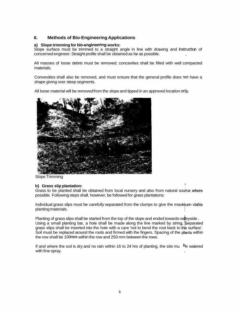
6. Methods of Bio-Engineering Applications
a) Slope trimming for bioengineering works: Slope surface must be trimmed to a straight angle in line with drawing and insttuction of concerned engineer. Straight profile shall be obtained as far as possible. I
All masses of loose debris must be removed; concavities shall be filled with well compacted materials. !
Convexities shall also be removed, and must ensure that the general profile does nht have a shape giving over steep segments. I ~ All loose material will be removed from the slope and tipped in an approved location only.
Slope Trimming 1
b) Grass slip plantation: I
Grass to be planted shall be obtained from local nursery and also from natural so possible. Following steps shall, however, be followed for grass plantations:
Individual grass slips must be carefully separated from the clumps to give the maxi planting materials.
Planting of grass slips shall be started from the top of the slope and ended towards va leyside . I Using a small planting bar, a hole shall be made along the line marked by string. Separated grass slips shall be inserted into the hole with a care 'not to bend the root back to tke surface'. Soil must be replaced around the roots and firmed with the fingers. Spacing of the plants within the row shall be 1 OOmm within the row and 250 mm between the rows. 1
If and where the soil is dry and no rain within 16 to 24 hrs of planting, the site mu e watered with fine spray. t

.- 1 1
Grass Planting
c) TreeIShrub plantation: Tree 1 shrub seedlings to be planted shall be obtained from project nursery. The plantations shall be undertaken as follows:
Site shall be prepared to ensure that its condition site is good enough for the successful establishment of tender and susceptible young plants.
The spacing the plants shall be determined according to individual site conditions.
Approved species of plant shall be supplied from the nursery. Plants must be about 300 mm in height above the soil surface with a proportionate root shoot ratio.
Planting shall be started at the top of the slope and ending at the valley side.
Pit must be prepared 300 mm x 300 mm in size and seedlings shall be planted, backfilled and compacted with feet.
Tree/Shrub Planting
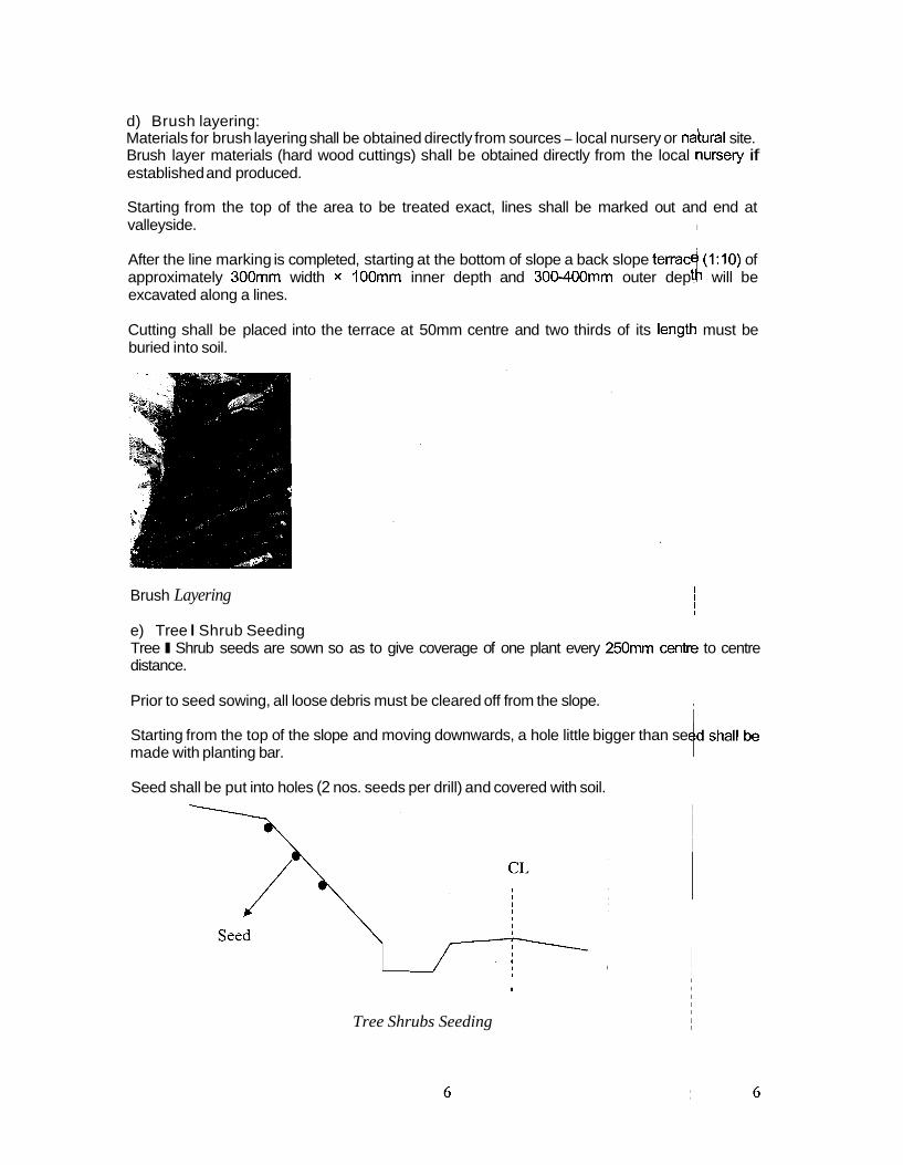
d) Brush layering: Materials for brush layering shall be obtained directly from sources - local nursery or nahral site. Brush layer materials (hard wood cuttings) shall be obtained directly from the local oursery if established and produced. I
I
Starting from the top of the area to be treated exact, lines shall be marked out and end at valleyside. I I
After the line marking is completed, starting at the bottom of slope a back slope terrac (1:lO) of approximately 300mm width x 100mm inner depth and 300-400mm outer dept i will be
I excavated along a lines.
Cutting shall be placed into the terrace at 50mm centre and two thirds of its lengtld must be buried into soil.
Brush Layering I I ~
e) Tree I Shrub Seeding I
Tree I Shrub seeds are sown so as to give coverage of one plant every 250mm cent& to centre distance. I
Prior to seed sowing, all loose debris must be cleared off from the slope. I
i Starting from the top of the slope and moving downwards, a hole little bigger than se made with planting bar.
Seed shall be put into holes (2 nos. seeds per drill) and covered with soil. ~
I
Tree Shrubs Seeding

f) Direct Broadcasting of Grass Seeds. Surface to be seeded must be scarified using a gardener's fork.
Starting from the top, grass seed shall be broadcasted liberally over the slope @ 25 gm/m2.
Grass Seeding Well Growing Grass Seed g) Fascines: Material for fascines (hardwood cuttings) shall be obtained directly from the source - local nursery or natural site.
Starting from the bottom of the area to be treated, exact line should be marked out. Starting from the bottom, trenches approximately 200 mm in depth should be excavated along the lines.
Cuttings should then be laid along each trench, so that they lie horizontally along the trench. There should normally be 'eight cuttings' together. They must also be overlapped so that no two ends coincide. Cuttings must then be tied using jute string at 500 mm intervals to form a bundle. As the fascine is created, it thereby forms a continuous bundle along the trench.
Trench should then be backfilled and gently compacted. The top of the fascine should be 50 to 100 mm below the surface. Any loose or excess material is cleared down the slope before the next fascine is laid.
Laying of fascines Cross Section
h) Bamboo plantation: Bamboo to be planted shall be obtained from the sources.- local farmers.

Suitable individual clump near the edge of the parent clump must be selected, separated and dug out with rhizome carefully.
Clump must be cut off 2 m above ground level (at the most).
Rhizome must be wrapped with damp hessian and transported to site. ,
Large hole i.e. 5 times the size of rhizome, must be dug and planted right angle to the slppe. Hole must be backfilled and compacted well.
I
I
I I I
7. Nursery Establishment I I
The bioengineering works requires big number of grass slips, shrub and trees. So it is needed to establish separate nursery in the project site itself to meet the demgnd. The proper location for the nursery shall be established in consultation with engineqr for the following reasons: ~ To produce required quantities of grass slips, shrub and trees in healthy condition. ~ To make available in the right time. I
It is unlikely to receive required quantities from other sources. ,
Nursery site selection is the key point in the success of the plantation project. ~ b n c e , the contractor shall consider the following main factors as mentioned below: I
I
Wherever possible, nursery shall be established on the road alignment areas. I
Nursery site shall be selected in such areas where there is a reliable and adequatesupply of water, which remains constant thought the year. I
I
Nursery shall be all weather vehicular access. I I
Nursery shall have a perimeter of stock proof fencing, effective against all domestic animals. Nursery shall have a weather and pest proof office cum seed store and prop r storage
clause 2801 and 2802 of Geo environment Unit of DoR.
4 facilities for seed. Seed must be kept cool, dry and in sealed containers, as sdecified in
I
Nursery must be provided with at least two above ground compost bays, built of stone, brick or timber. These shall be used on an alternative basis to ensure a continual (supply of compost. I I
I
Where a nursery is established an a slope exceeding 2' the ground shall be leveled by terracing before beds are constructed. , I
8. Nursery operation and Management: I I
The project shall operate the nursery according to high standard. The nursery /s to be staffed well tended at all times. It would be maintained in a clean, tidy and efficiept manner at all times. Plants shall always be healthy and vigorous. I I
Plants must be kept properly weeded at all times. ,
Watering, as required for good plant growth, must be carried out regularly in the 6001 of the evening between the sunset and dusk. The contractor shall ensure that the soil in all beds is

kept moist but not saturated at all times. Beds must kept moist even when empty, so that the soil is kept in good condition.
The timing of all nursery operations is of the utmost importance. Activities such as seed sowing and taking of cutting must be carried out within the critical few weeks when they will yield the desired results. Most other operations, such as spacing out, root pruning and watering must also be carried out in timely manner.
The purpose of nursery is to supply good quality, healthy plants of the correct type of species, at the precise time they are required, and at a reasonable cost.

Appendix 3: Rate ~ n a i ~ s i s


Rate Analysis for Bio-Engineering Works
27(2)(a) Collection of grass clumps (e. g. amliso,Kans, Khar, Phurke, salimo, Babiyo etc.) from sourkes within 1 km of road.
Unit: I O O ~ NOS
27(8)(f) Planting rooted grass slips on slopes 45'- 60°including preparation of slips on site. operati+ includes digging planting hole to a maximum of 5 cm depth with metal rod or hard wood peg, depenping on nature of soil. The planting drills should be 1
Hence, Rate per nos. of seedling = 5.46 I
I
Rate(Nrs)
165.00
20.00
S.N. 1
2
3
Add 15% overhead & profit
Total cost
Unit
PD
s ~ m
Description
Labour
a) Unskilled
Material
a) hessian jute Tools & plants(3% of labour cost)
Total direct cost
5.53
34.90
Quantity
1.50
5.00
Amount(Nrs)
247.50
100.00
7.43
354.93
Ratel sqm=Nrs 34.90
~emajks
~

27(4)(b) Preparing potting mix and filling polypots, including all materials for container seedings.( Note: 1 kg of 200 gauge polypots (4" x 7" laid flat)=464 bags.
Unit:1000 Nos.
Hence, Rate per nos. of seedling = 2.81
27(4)(c) Direct sowing of treelshrub seeds into polypots including seed treaternent, by sowing one seed in half the pots and two seeds in the other half.
Unit1 000 Nos.
Hence, Rate per nos. of seedling = 0.33 Total production cost of seeding per nos.=27(3)(b)+27(4)(b)+27(4)(c) =Nrs 8.60
27(9)(c) Planting containerised tree and shrub seedlings, including pitting, transplanting, composting and mulching, on slopes 30'- 45'. Pit size 30 cm diameter x 30 cm depth. Mix compost with soil and backfill into pit, to 114 of pit volume.
Unit:lO Nos.
Rate per nos. of seedling =Nrs 19.85

27(10)(a) Collection of hardwood cutting for planting material (eg. Assuro, namdiphul, simali etc. or appropriate for the area) from sources within 1 km of road. Material to be approx 1 m in length and minimum 5 cm in diameter.
Unit: 100d Nos
27(10)(b) Preparation and planting of live cuttings of selected species (e.g. Assuro, bains, kandaful, ) saruwa, simali or approppriate for the area) of minimum I m length to 0.5 m into hard ground.Pegs ~ spaced at 5 cm center within the row and interwoven wi
I I
Unit: I MI
/ ~ o t a l cost 36.551 ) 1 Ratelm.=Nrs 36.55
I
27(7)(d) Sowing shrub or tree seeds on all slopes at 25 cm intervals, including diging planting hole4 to 5 cm depth and covering with soil. Two seeds per planting holes. I
I
I
27(7)(a) Broadcasting grass seeds on slopes c40°, seeding rate 25 gmlm2 I I
Unit: 104 Sqm
Unit: 100 Sqm
Quantity
0.17
2.50
8.95
Rate(Nrs)
165.00
300.00
S.N.
1
2
S.N.
I
Amount(Nrs)
28.05
750.00
778.05
116.71
894.76
Description
Labour a) Unskilled
Material
a) Seeds
Total direct cost
Add 15% overhead and profit
Total cost
Unit Description
Labour
~emdrks I l
I I I l
Unit
PD
kg
Rate1 Sqm.=Nrs
Quantity Rate(Nrs) Amount(Nrs) Remarks

27(10)(d) Site preparation for fascine laying: earthwork work in excavation of trench to 20 cm depth.
Unit: I m - . . . -. . . . .
s.N./ Description I Unit I Quantity / Rate(Nrs) I~mount(Nrs)/ Remarks
la) Unskilled I PD 0.061 165.00 1 9.90)
21 Material
Rate/ m.= 10.20 27(10)(e) Laying of live fascines, using live hardwood cuttings of selected species (eg. Assuro, namdi phul, simali etc. or appropriate for the area) of minimum 1 m length, placed in bundles to give 8 running meters of cuttings per meter of fascines, incl
3 Tools & plants(3% of labour cost) Total direct cost
Unit: I m S.N.
1
2
24.Supply and planting of large bamboo in gully or landslide(traditiona1 planting) having sufficient rhizome and atleast 2 m of culm above ground.
Unit: I m
0.30
10.20
3
- --
Description
Labour
a) Unskilled
Material
a) Hardwood cuttinas
Tools & plants(3% of labour cost)
Total direct cost
Add 15% overhead and profit
Total cost
S.N. 1
P D
Nos
0.84 30.05
4.51
34.55
la) Unskilled I PD
Unit
Description
Labour
-
3
Quantity Rate(Nrs)
0.17
8.00
0.061 165.001 9.90
Total direct cost
Add 15% overhead and profit
Total cost
~mount(Nrs)] Remarks
- -
u n i t
Ref: Rate
. . . - . - . - .
a) Large bamboo
Tools & plants(3% of labour cost)
5(a) Slope preparation for bio engineering works in soft debris soil and disposal of material to the approved locations(average depth 15cm)
Unit: Sqm
165.00
0.14
analysis 21 Material
RatelNos=Nrs 126.73
110.20
16.53
126.73
~ u a n t i t ~
1 Nos
conservation, clause 24.
Remarks
0.1 5*0.7= 0.105 PD
S.N.
1
28.05
1 .I 6 Ref:27110Ma)
Rate(Nrs)
1 .OO
Add 15% overhead and profit
Total cost
2.60 19.92
Description
Labour
a) Unskilled
Total direct cost
~m;nt(~;)
100.00
Rate(Nrs)
165.00
Rate1 Sqm.=Nrs 19.92
Remarks
Amount(Nrs)
17.33
17.33
Unit
PD
100.OO 0.30
Quantity
0.1 1
norms of ministry of forest and soil

ANN EX-A
Rate Analysis for Bio-Engineering Works
27(2)(a) Collection of grass clumps (e. g. amliso,Kans, Khar, Phurke, salimo, Babiyo etc.) from Sources within 1 km of road.
Unit: 1000 Nos
I
27(8)(f) Planting rooted grass slips on slopes 45'- 60°including preparation of slips on site. 0~4ration includes digging planting hole to a maximum of 5 cm depth with metal rod or hard wood peg, dcbpending on nature of soil. The planting drills should be spaced 100 mm within the row and 250 mm beqeen the row. I I
Unit! I sam
S.N.
1
2
3
Unit
PD
sqm
Description
Labour
a) Unskilled
llrlaterial
a) hessian jute
Tools & plants(3% of labour cost)
Total direct cost
I I
Quantity
1.50
5.00
2
3
S.N.
1
Add 15% overhead & profit
Total cost
Rate(Nrs)
165.00
Material
a) grass slips
b) hessian jute
Tools & plants(3% of labour cost) Total direct cost
~dmarks
I ~ ~
Rate(Nrs)
165.00
20.00
Description
Labour
a) Unskilled
5.53
34.90
Amount(Nrs)
247.50
100.00
7.43
354.93
Amount(Nrs)
19.80
Nos
s ~ *
I ~ I
Unit
PD
demarks Quantity
0.12
40.00
0.1 1 0.35
20.00 14.20
2.25
0.59
36.84
Ref: 27(2)(a)
~ I ~

AN N EX-A
27(3)(b) Construction of standout beds for tree seedlings in polypots, including material for beds and shades. Bed is 100 cm wide x 15 cm high, with 5 cm layer of gravelplaced above the compacted ground,
- - -- TTOOIS & plants(3% of labour cost) 1 29.70) !Total direct cost 3057.961
1 Sqm of bed stand 128 Nos of 4" x 7" polypots. Hence, Rate per nos. of seedling = 5.32
Hence, Rate per nos. of seedling = 2.81
27(4)(b) Preparing potting mix and filling polypots, including all materials for container seedings.( Note: 1 kg of 200 gauge polypots (4" x 7" laid flat)=464 bags.
Unit:1000 Nos.
27(4)(c) Direct sowing of treelshrub seeds into polypots including seed treatement, by sowing one seed in half the pots and two seeds in the other half.
Unit:1000 Nos.
Hence, Rate per nos. of seedling = 0.33 Total production cost of seeding per nos.=27(3)(b)+27(4)(b)+27(4)(c) =Nrs 8.46
S.11. 1
2
3
Rate(Nrs)
165.00
0.27 1235.00 300.00
214.50
Description Labour a) Unskilled Material
a) Polypot b) Sand c)Soil
d) Compost Tools & plants(3% of labour cost) Total direct cost
Amount(Nrs)
1650.00
283.50 568.10 21 0.00
49.34 49.50
2810.44
Unit
PD
Nos. Cum Cum
Cum
Remarks
N rs 1251464=0.27
1.3 mdlcum, ref:27(6)(b+c)
Quantity
10.00
1050.00 0.46 0.70
0.23

ANN EX-A
27(9)(c) Planting containerised tree and shrub seedlings, including pitting, transplanting, composting and mulching, on slopes 30'- 45'. Pit size 30 cm diameter x 30 cm depth. Mix compost with soil and backfill into pit, to 114 of pit volume.
nit:^^^ NOS.
Rate per nos. of seedling =Nrs 19.69 I ,
27(10)(a) Collection of hardwood cutting for planting material (eg. Assuro, namdiphul, simali etcl or appropriate for the area) from sources within 1 km of road. Material to be approx 1 m in length and minimum 5 cm in diameter. ~
27(10)(b) Preparation and planting of live cuttings of selected species (e.g. Assuro, bains, kand~aful, saruwa, simali or approppriate for the area) of minimum 1 m length to 0.5 m into hard gr0und.P~eg.s spaced at 5 cm center within the row and interwoven with vegetation. i.e Brush Layering I
I
unit; 1 M.
S.N. 1
2
3
Add 15% overhead and profit Total cost
Unit
PD
Nos. Cum Cum
Rate(Nrs)
165.00
8.46 214.50 1 98.00
Description Labour a) Unskilled Material
a) Seedlings b) Compost c) Green mulch Tools & plants(3% of labour cost) Total direct cost
Quantity
0.40
10.00 0.05 0.04
Amount(Nrs)
66.00
84.60 10.73 7.92 1.98
171.23 25.68
196.91
Relmarks
I I
Ref: 2?(3)(b) +27(4\(b)+ 27(4) P
1.2 rrd/Cum
I I I I I

ANN EX-A
27(7)(a) Broadcasting grass seeds on slopes <40°, seeding rate 25 gm/m2.
27(7)(d) Sowing shrub or tree seeds on all slopes at 25 cm intervals, including diging planting holes to 5 cm depth and covering with soil. Two seeds per planting holes.
Unit: 100 Sam
27(1 O)(d) Site preparation for fascine laying: earthwork work in excavation of trench to 20 cm depth. Unit: Im.
Is.N.1 Descri~tion I Unit I Quantitv I Rate(Nrs) I~rnount(Nrsd Remarks 1 1
2
3
Labour
a) Unskilled
Material
Tools & plants(3% of labour cost)
Total direct cost
PD 0.06 165.00 9.90
0.30
10.20

AN I\I EX-A
27(10)(e) Laying of live fascines, using live hardwood cuttings of selected species (eg. Assuro, namdi phul, simali etc. or appropriate for the area) of minimum 1 m length, placed in bundles to give 8 running meters of cuttings per meter of fascines, including backfilling of trench and careful compaction. :
24.Supply and planting of large bamboo in gully or landslide(traditiona1 planting) having sufficien4 rhizome and atleast 2 m of culm above ground. I
Unit: I m
Unit: ? m
S.N. 1
2
3
I
I 5(a) Slope preparation for bio engineering works in soft debris soil and disposal of material to tqe approved locations(average depth 15cm) I
S.N.
'I
2
I 3
unit] Sam
Ratelm.=27(1 O)(d)+27(1 O)(e)=Nrs 44.75
Description
Labour
a) Unskilled
Material a) Hardwood cuttings
Tools & plants(3% of labour cost)
Total direct cost Add 15% overhead and profit
Total cost
Description
Labour
a) Unskilled
Material
a) Large bamboo
Tools & plants(3% of labour cost)
Total direct cost
Add 15% overhead and profit
Total cost
Unit
PD
Nos
Unit
PD
Nos
Remarks
Quantity
0.17
8.00
S.IV.
1
Quantity
0.06
1 .OO
a) Unskilled Total direct cost
Add 15% overhead and profit
Total cost
Unit Description
Labour
Rate(Nrs)
165.00
0.14
Rate(Nrs)
165.00
100.00
PD
Quantity
Amount(Nrs)
28.05
1.16
0.84
30.05
4.51
34.55
Amount(Nrs)
9.90
100.00
0.30 1 10.20
I 6.53
126.73
2.60 ~ 19.92 ~
0.1 1
Rate(Nrs)
Reinarks
I
~
-
~dmarks l
Ref: kate analysis
?'$;bf fore t and soil cons rvation, 1 c~au)e 24.
~
Amount(Nrs)
Ref:27(1
165.00
O)(a)
, I
17.33
17.33
0.1 5(*0.7= O.lq5 PD
I
(


Appendix 4: Forr)lats