site specifications for the vitros 3600 immunodiagnostic...
TRANSCRIPT

Publication No. J327482016-10-03
Supersedes J327482016-07-21
Site Specificationsfor the
VITROS® 3600 Immunodiagnostic System
PLEASE NOTE The information contained herein is based on the experience and knowledge relating to the subject matter gained by Ortho Clinical Diagnostics (Ortho) prior to publication.
No patent license is granted by this information.
Ortho reserves the right to change this information without notice, and makes no warranty, expressed or implied, with respect to this information. Ortho shall not be liable for any loss or damage, including consequential or special damages, resulting from any use of this information, even if loss or damage is caused by the negligence or other fault of Ortho.
This equipment includes parts and assemblies sensitive to damage from electrostaticdischarge. Use caution to prevent damage during all service procedures.
Description Page
Table of Contents
Electrical Power Requirements . . . . . . . . . . . . . . . . . . . . . . . . . . . . . . . . . . . . . . . . . . . . 3Electrical Specifications for the System . . . . . . . . . . . . . . . . . . . . . . . . . . . . . . . . . . . . . 4Electrical Specifications for the Supplied PRINTER . . . . . . . . . . . . . . . . . . . . . . . . . . 6RECEPTACLE Location Specifications . . . . . . . . . . . . . . . . . . . . . . . . . . . . . . . . . . . . 7Environmental Specifications . . . . . . . . . . . . . . . . . . . . . . . . . . . . . . . . . . . . . . . . . . . . . 8Networking Specifications . . . . . . . . . . . . . . . . . . . . . . . . . . . . . . . . . . . . . . . . . . . . . . . . 9Requirements at Customer Site . . . . . . . . . . . . . . . . . . . . . . . . . . . . . . . . . . . . . . . . . . . 10Shipping Specifications . . . . . . . . . . . . . . . . . . . . . . . . . . . . . . . . . . . . . . . . . . . . . . . . . . 11Specifications for the System and the PRINTER . . . . . . . . . . . . . . . . . . . . . . . . . . . . . 12Specifications for the 3600 HEAT REJECTION PLENUM. . . . . . . . . . . . . . . . . . . . . 13
2 2016-10-03 – J32748

Electrical Power Requirements
Section 1: Electrical Power Requirements
AC Power QualityThe VITROS 3600 Immunodiagnostic System (hereafter referred to as the System) is designed to perform satisfactorily with reasonable disturbances and voltage tolerance to the ac power. The quality and reliability of the power source is often dependent on the geographic location of the site. Some sites, where power quality is exceptionally poor, may require special power conditioning equipment to ensure that the tolerances are maintained within acceptable limits. Some models of UNINTERRUPTIBLE POWER SUPPLIES (UPS) are recommended as optional equipment for use with VITROS Systems, and may be purchased from the Distribution Center. See the UPS service publication for additional information.
Static ElectricityThe System should be adequately grounded to prevent the effects of static charges generated. Static problems can also be reduced by ensuring that the relative humidity of the room is maintained above 30 percent. Special anti-static floor pads can be purchased and positioned where the operator is required to make contact with the instrument.
Electromagnetic InterferenceSeveral types of electrical interference may be indigenous to the site location and may require special filtering to prevent malfunctions in the System. If interference is suspected to be a problem, shielding may be required, or filtering of the ac line power to the site may be necessary.
Cellular phones, two-way pagers, and other RF transmitting devices should not be used within 1 m of the 3600 System.
2016-10-03 – J32748 3
Section 2: Electrical Specifications for the System
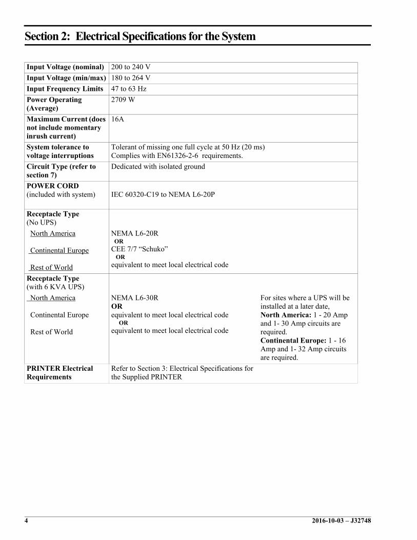
Input Voltage (nominal) 200 to 240 V
Input Voltage (min/max) 180 to 264 V
Input Frequency Limits 47 to 63 Hz
Power Operating (Average)
2709 W
Maximum Current (does not include momentary inrush current)
16A
System tolerance to voltage interruptions
Tolerant of missing one full cycle at 50 Hz (20 ms)Complies with EN61326-2-6 requirements.
Circuit Type (refer to section 7)
Dedicated with isolated ground
POWER CORD(included with system) IEC 60320-C19 to NEMA L6-20P
Receptacle Type (No UPS)
North America
Continental Europe
Rest of World
NEMA L6-20R ORCEE 7/7 “Schuko” ORequivalent to meet local electrical code
Receptacle Type (with 6 KVA UPS)
North America
Continental Europe
Rest of World
NEMA L6-30R ORequivalent to meet local electrical code ORequivalent to meet local electrical code
For sites where a UPS will be installed at a later date, North America: 1 - 20 Amp and 1- 30 Amp circuits are required.Continental Europe: 1 - 16 Amp and 1- 32 Amp circuits are required.
PRINTER Electrical Requirements
Refer to Section 3: Electrical Specifications for the Supplied PRINTER
4 2016-10-03 – J32748

Electrical Specifications for the System
NoteCEE 7/7 “Schuko” plug may be supplied, either straight or right angle.
L1 L2
SAFETYGROUND
NEMA L6-20R for 200 V ac - 240 V ac
E002_1332ACA
208 V Check between Voltage
60 Hz L1 - L2 190 - 220 V AC
L1 - SAFETY GROUND 113 - 127 V AC
L2 - SAFETY GROUND 113 - 127 V AC
240 V Check between Voltage
60 Hz L1 - L2 226 - 254 V AC
L1 - SAFETY GROUND 113 - 127 V AC
L2 - SAFETY GROUND 113 - 137 V AC
2016-10-03 – J32748 5

Section 3: Electrical Specifications for the Supplied PRINTER
ImportantThe following information is only applicable to PRINTERS supplied by OCD. If the PRINTER is being supplied by the customer, refer to the manufacturer’s PRINTER manual for the electrical specifications.
Detach 1
1 RECEPTACLE required 3-wire, 120 V AC, polarized, SAFETY GROUND, maximum distance of 182.7 cm (72 in.) from each side of the system.
CIRCUIT Type Dedicated
120 V Check between Voltage
60 Hz N - L1 102 - 132 V AC
15 amperes L1 - SAFETY GROUND 102 - 132 V AC
N - SAFETY GROUND Less than 1 V AC
E002_1331ACE002_1331ACA
RECEPTACLEpolarized power
GROUNDSAFETY
L1
N
NEMA 5-15R
6 2016-10-03 – J32748

RECEPTACLE Location Specifications
Section 4: RECEPTACLE Location Specifications
Specifications for PRINTER POWER and NETWORK CONNECTION
Specifications for the System only
Detach 2
Reference Description
Q (height from floor)
30.5 cm (12 in.) minimum
61.0 cm (24 in.) maximum
S (printer power)
2.9 m (8 ft. 10 in.) maximum
T (Network)
5.3 m (17 ft. 6 in.) maximum
Reference Description
Q (height from floor)
30.5 cm (12 in.) minimum
61.0 cm (24 in.) maximum
R (system power)
1.98 m (6 ft. 6 in.) maximum
Q
Q
S
S
R
R
T
T
Q
Q
2016-10-03 – J32748 7

Section 5: Environmental Specifications
Detach 3
Maximum altitude: 2438 m (8000 ft.)
This product has been evaluated and is suitable only for Pollution Degree II and Insulation Category II.
Additional Requirements for the 3600 System HEAT REJECTION PLENUM
If the customer chooses to purchase and use the optional Heat Rejection Plenum, the EXHAUST SYSTEM and 2 DUCTS must be installed by the customer.
ImportantA HEAT REJECTION PLENUM and an AT CONVERSION KIT cannot both be installed at the same time.
Acoustic Noise Level Idle: 60 dBOperational: 65 dB
Thermal Characteristics
On 6130 BTU/hr
Specifications per DUCT
Air Capacity7.1 - 9.9 cubic metres (250 - 350 cubic ft.) per minute259 - 366 metres (850 - 1200 ft.) per minute
DUCT (each)20.5 cm (8 in.) flexible AIR DUCT and attaching hardware
Air Flow - Ventilation System7.1 - 9.9 cubic metres (250 - 350 cubic ft.) per minute at 5.1 mm (0.2 in.) of water vacuum
8 2016-10-03 – J32748

Networking Specifications
Section 6: Networking Specifications
Network Connection SpecificationsThe requirements for e-Connectivity network connection are located in the Network Information Form located on-line at: http://apps.orthoclinical.com/notes/contentpages/techdoc.aspx?view=USSPECS
The customer must complete the form and return it to Ortho Clinical Diagnostics.
ImportantAll requirements for lab network connections must be completed before installation of the analyzer(s).
2016-10-03 – J32748 9

Section 7: Requirements at Customer Site
TELEPHONE A TELEPHONE located so that the user can move around the System must be available.
Air Flow No air flow sources directed towards the system within 3.0 m (10 ft).
Entrance to the room where the System will be installed
Minimum width of 81.3 cm (32 in.)
LAB COMPUTER Interface See the Interface Specification section of the Operator’s Manual.
Network Connection Refer to the Networking Specifications on page 9.
Floor Loading 433.4 kg/m2 (88.9 lb./ft2)
Circuit Breakers 2 circuit breakers capable of handling high in-rush current. In Europe, the following applies:1 dedicated line with 16A 'D' type circuit breaker
For systems equipped with a UPS:1 dedicated line 32A 'D' type circuit breaker
10 2016-10-03 – J32748
Shipping Specifications
Section 8: Shipping Specifications
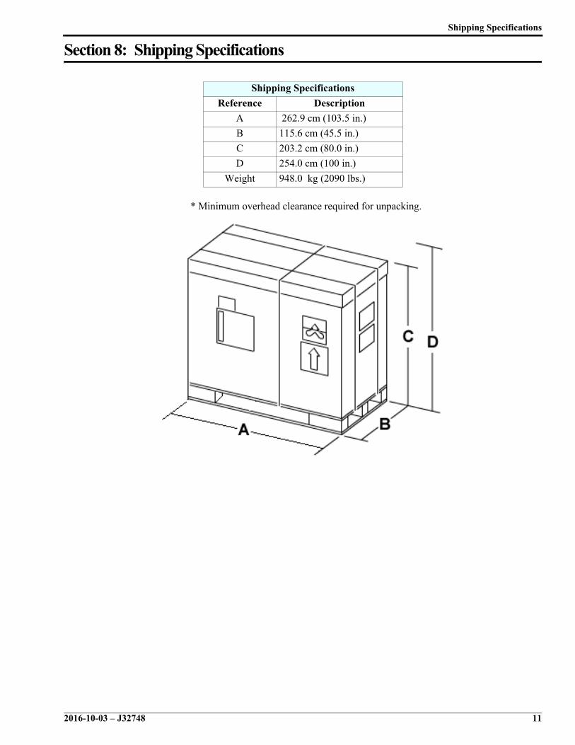
* Minimum overhead clearance required for unpacking.Detach 4
Shipping Specifications
Reference Description
A 262.9 cm (103.5 in.)
B 115.6 cm (45.5 in.)
C 203.2 cm (80.0 in.)
D 254.0 cm (100 in.)
Weight 948.0 kg (2090 lbs.)
2016-10-03 – J32748 11

Section 9: Specifications for the System and the PRINTER
System Specifications Supplied PRINTER Specifications ****
Reference Description Reference Description
A 212 cm (83.5 in.) J 40.0 cm (15.7 in.)
B 88.7 cm (34.9 in.) K 51.3 cm (20.2 in.)
C 163.8 cm (64.5 in.) L 34 cm (13.4 in.)
D 213.4 cm (84.0 in.) M 61 cm (24 in.)
Weight 789.2 kg (1740 lb.) Weight 19.7 kg (43.5 lb.)
PortPrinter Language
USB Version 2.0Post Script
Installation Specifications for the System only
Installation Specifications for the Supplied PRINTER ****
Reference Description Reference Description
E 76.2 cm (30.0 in.) N 17.8 cm (7.0 in.)
F 76.2 cm (30.0 in.)Required clearance for opening side door to allow service access. Does not include PRINTER
O 45.7 cm (18.0 in.)
It is acceptable to have moveable objects (such as a PRINTER STAND) within this area, but no closer than 61 cm (24 in.) to the system.
P 61.0 cm (24.0 in.)Requirement for proper system airflow. No objects should be located within this space.
G 45.7 cm (18.0 in.) ** **** If the PRINTER is being supplied by the customer, refer to the manufacturer’s PRINTER manual for any specifications.
Q 76.2 cm (30.0 in.)** 91 cm (36 in.) if SEISMIC ANCHORAGES, AT Accessory Kit or HEAT REJECTION PLENUM are to be installed.
B
AISLEN
Q
G
K
L
J
D
C
O
F
P
A
E
M
12 2016-10-03 – J32748

Specifications for the 3600 HEAT REJECTION PLENUM
Section 10: Specifications for the 3600 HEAT REJECTION PLENUM
Detach 5
Detach 6
HEAT REJECTION PLENUMSpecifications
Reference Description
A 89.1 cm (35.1 in.)
B 74.5 cm (29.3 in.)
C 31.5 cm (12.4 in.)
D 16.0 cm (6.3 in.)
E 14.5 cm (5.7 in.)
2016-10-03 – J32748 13

IVD
EC REP
Ortho Clinical DiagnosticsFelindre MeadowsPencoedBridgendCF35 5PZUnited Kingdom
Ortho Clinical Diagnostics100 Indigo Creek DriveRochester, NY 14626USA