siting transmission lines & substations · siting transmission lines & substations ... 14....
TRANSCRIPT
Siting Transmission Lines & Substations
Salt Lake County Electrical Plan Task Force
December 3rd
Mickey BeaverCustomer and Community Manager
Rocky Mountain Power
1
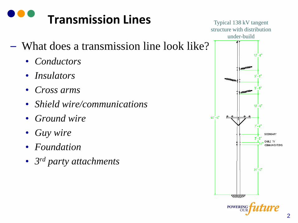
– What does a transmission line look like?
• Conductors
• Insulators
• Cross arms
• Shield wire/communications
• Ground wire
• Guy wire
• Foundation
• 3rd party attachments
Transmission Lines Typical 138 kV tangent
structure with distribution
under-build
2
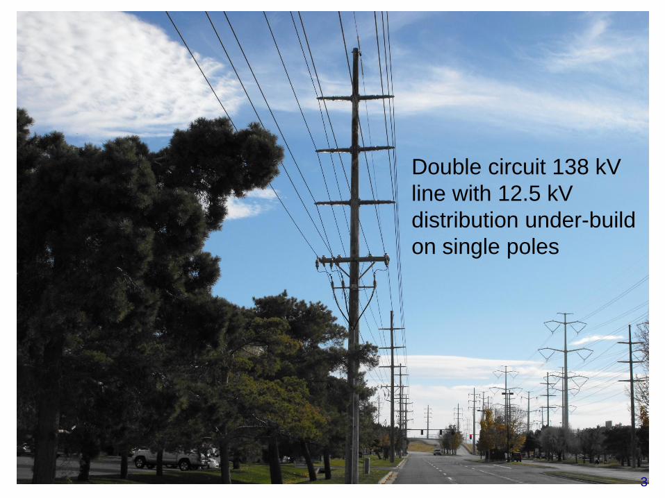
Double circuit 138 kV
line with 12.5 kV
distribution under-build
on single poles
3
– What is needed to serve the future load
• 5 years?
• 10 years?
• 50 years?
– Company standards
• Avian safe (set by federal regulations)
• Standard materials (restoration and cost)
– Federal, state, and local regulations
• NESC (National Electrical Safety Code)
• WECC (Western Electricity Coordinating Council)
• NERC (North American Electric Reliability Corporation)
– Right of way
• Access for construction, maintenance, and repair
Transmission Design
4

– Plan for the future - This is why we are here!
• Build once or build and re-build and re-build and re…
• Incorporate community’s master plans and vision within
the confines of existing regulations
Something to think about…when we plan for the future, do
we keep our options open or close the door?
Transmission Design – What is needed?
5
Transmission Line Capacity
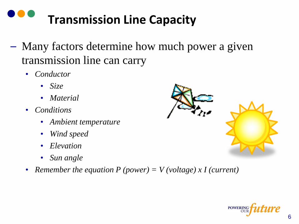
– Many factors determine how much power a given
transmission line can carry• Conductor
• Size
• Material
• Conditions
• Ambient temperature
• Wind speed
• Elevation
• Sun angle
• Remember the equation P (power) = V (voltage) x I (current)
6
Transmission Line Capacity
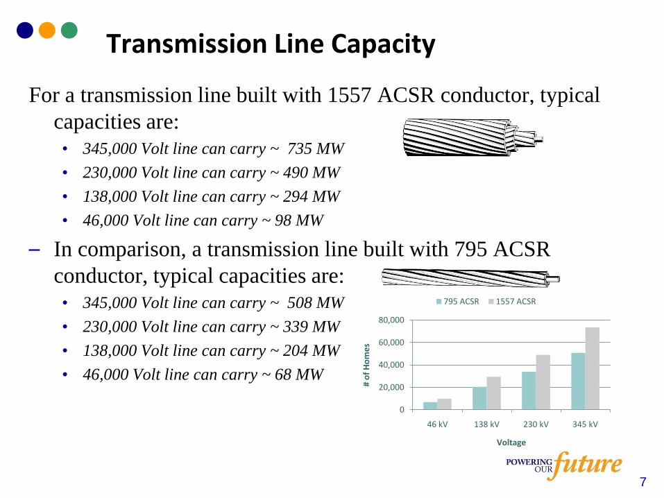
For a transmission line built with 1557 ACSR conductor, typical
capacities are:
• 345,000 Volt line can carry ~ 735 MW
• 230,000 Volt line can carry ~ 490 MW
• 138,000 Volt line can carry ~ 294 MW
• 46,000 Volt line can carry ~ 98 MW
– In comparison, a transmission line built with 795 ACSR
conductor, typical capacities are:
• 345,000 Volt line can carry ~ 508 MW
• 230,000 Volt line can carry ~ 339 MW
• 138,000 Volt line can carry ~ 204 MW
• 46,000 Volt line can carry ~ 68 MW
7
0
20,000
40,000
60,000
80,000
46 kV 138 kV 230 kV 345 kV
# o
f H
om
es
Voltage
795 ACSR 1557 ACSR
– Avian safety
• Lines are designed to mitigate accidental electrocution of
protected species
o Minimum clearances between energized conductors and grounded
components are mandated by federal law
– Standard materials
• Use of standard materials minimizes restoration time
when a component fails
Transmission Design – Company Standards
8
Transmission Design – Government Regulations
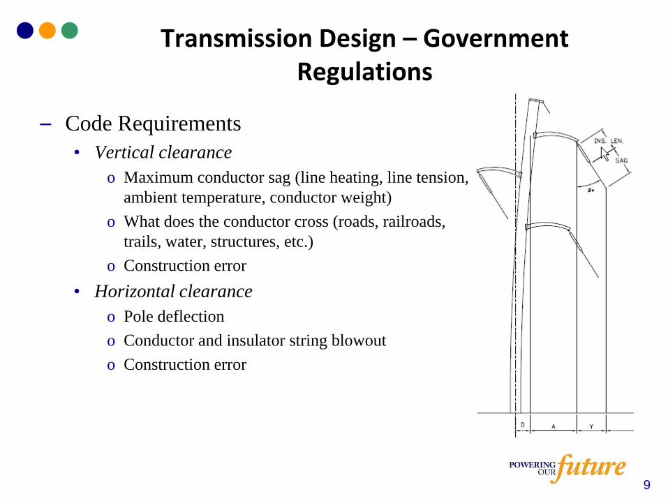
– Code Requirements
• Vertical clearance
o Maximum conductor sag (line heating, line tension,
ambient temperature, conductor weight)
o What does the conductor cross (roads, railroads,
trails, water, structures, etc.)
o Construction error
• Horizontal clearance
o Pole deflection
o Conductor and insulator string blowout
o Construction error
9
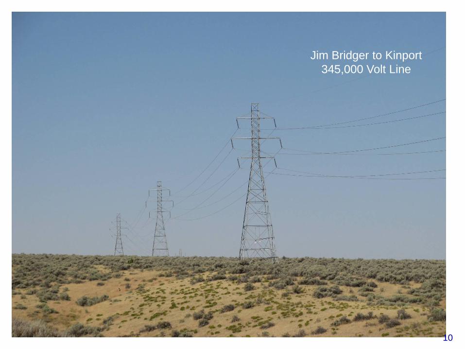
Jim Bridger to Kinport
345,000 Volt Line
10
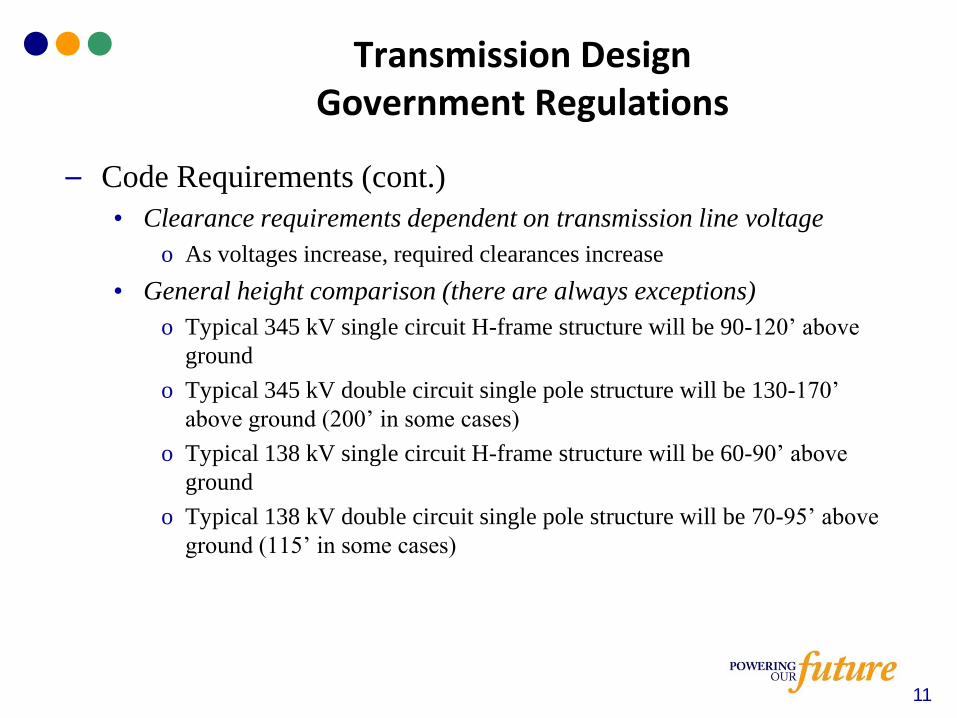
– Code Requirements (cont.)
• Clearance requirements dependent on transmission line voltage
o As voltages increase, required clearances increase
• General height comparison (there are always exceptions)
o Typical 345 kV single circuit H-frame structure will be 90-120’ above
ground
o Typical 345 kV double circuit single pole structure will be 130-170’
above ground (200’ in some cases)
o Typical 138 kV single circuit H-frame structure will be 60-90’ above
ground
o Typical 138 kV double circuit single pole structure will be 70-95’ above
ground (115’ in some cases)
Transmission Design Government Regulations
11
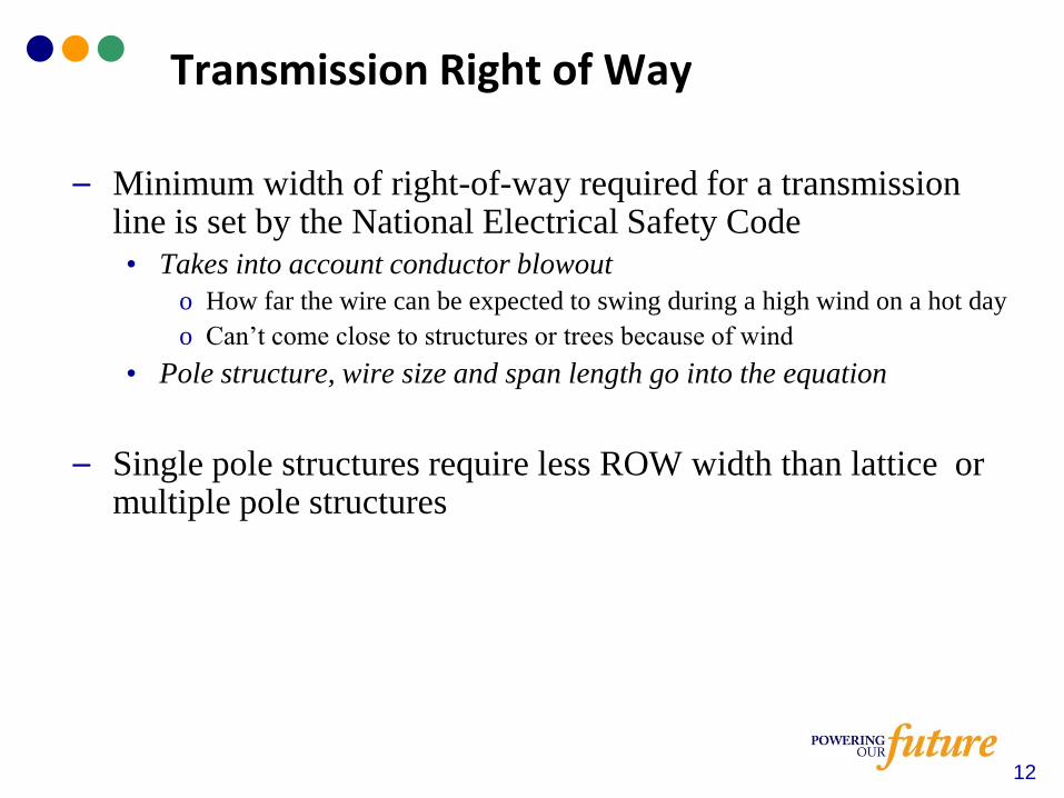
– Minimum width of right-of-way required for a transmission line is set by the National Electrical Safety Code
• Takes into account conductor blowout
o How far the wire can be expected to swing during a high wind on a hot day
o Can’t come close to structures or trees because of wind
• Pole structure, wire size and span length go into the equation
– Single pole structures require less ROW width than lattice or multiple pole structures
Transmission Right of Way
12
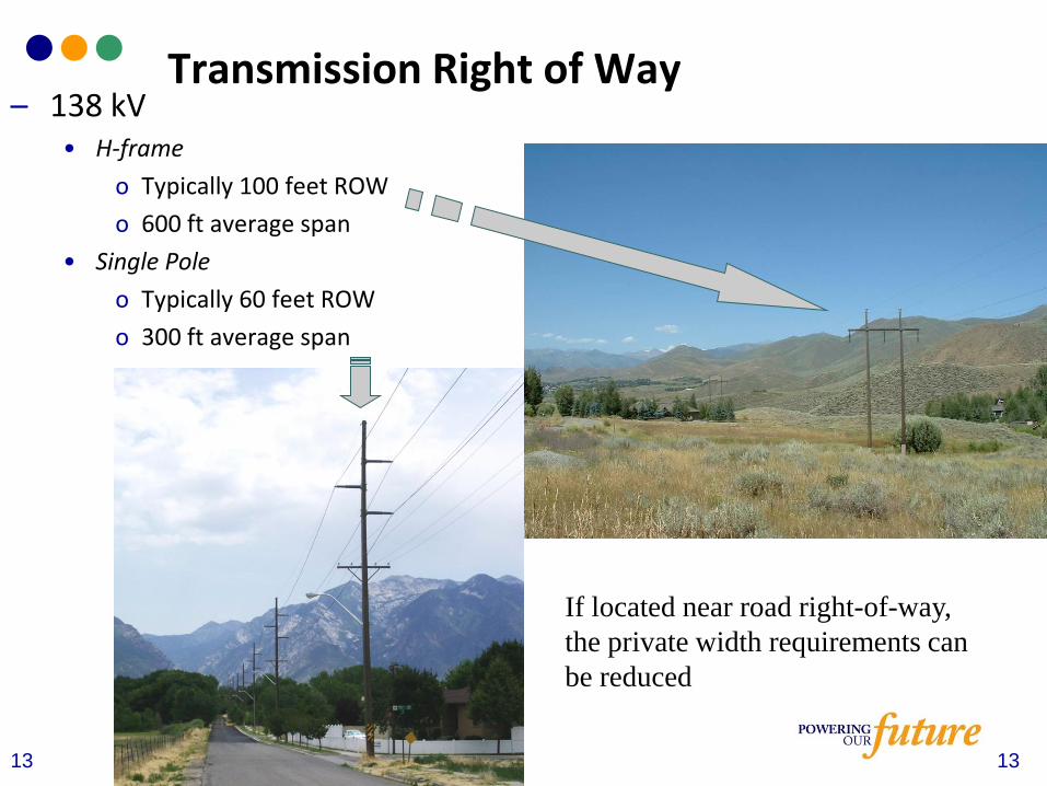
– 138 kV• H-frame
o Typically 100 feet ROW
o 600 ft average span
• Single Pole
o Typically 60 feet ROW
o 300 ft average span
13
If located near road right-of-way,
the private width requirements can
be reduced
Transmission Right of Way
13
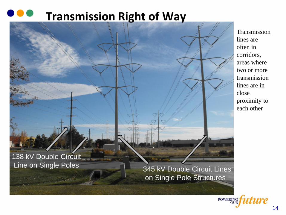
345 kV Double Circuit Lines
on Single Pole Structures
138 kV Double Circuit
Line on Single Poles
Transmission Right of WayTransmission
lines are
often in
corridors,
areas where
two or more
transmission
lines are in
close
proximity to
each other
14
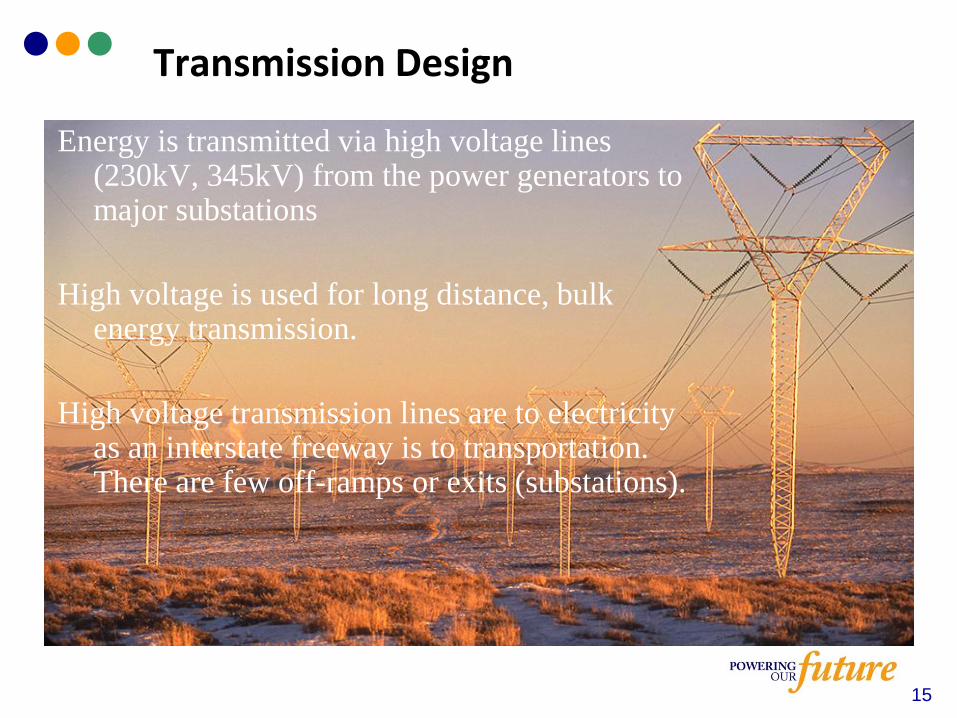
Transmission Lines (Main Grid)
Energy is transmitted via high voltage lines (230kV, 345kV) from the power generators to major substations
High voltage is used for long distance, bulk energy transmission.
High voltage transmission lines are to electricity as an interstate freeway is to transportation. There are few off-ramps or exits (substations).
15
Transmission Design
16
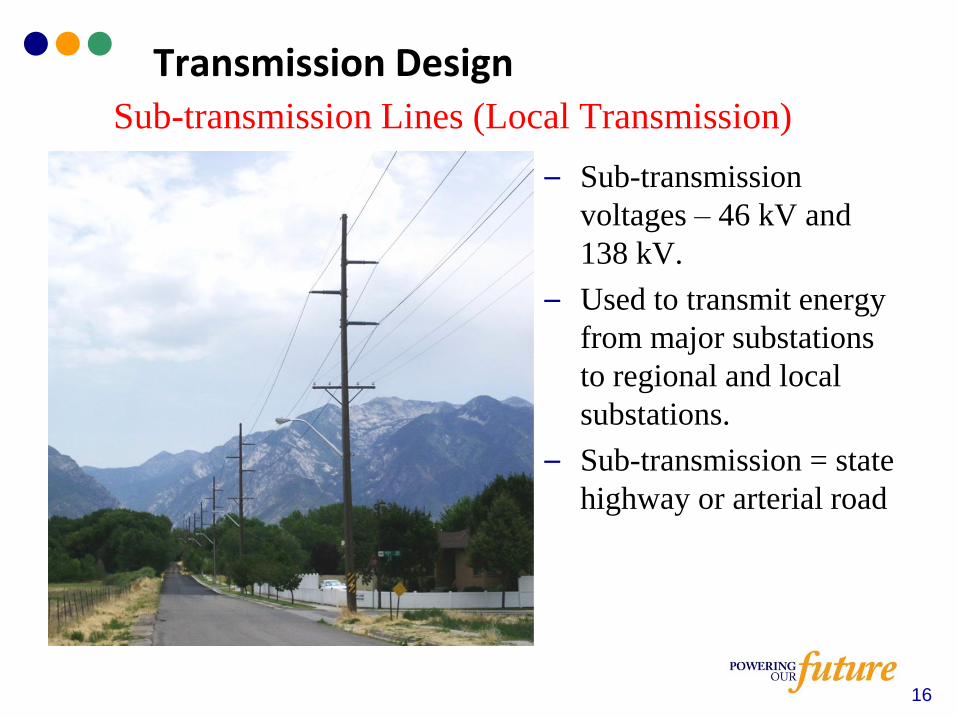
– Sub-transmission
voltages – 46 kV and
138 kV.
– Used to transmit energy
from major substations
to regional and local
substations.
– Sub-transmission = state
highway or arterial road
Sub-transmission Lines (Local Transmission)
Transmission Design
Transmission Reliability
– When do you want your power?
– Rocky Mountain Power must provide reliable service under all
normal operating conditions and prefers to serve the majority of
customers under expected abnormal operating conditions
– An abnormal operation condition is the loss of one or more
electrical components. These include:
– Generators (power plants)
– Transmission lines
– Substation transformers
17

Transmission Reliability
– Rocky Mountain Power complies with Western Electricity
Coordinating Council (WECC) reliability standards
– Reliability standards are federally mandated and include penalties
for poor reliability performance (>=100 kV)
– Rocky Mountain Power must periodically submit reports to the
reliability councils
– Public Service Commission has some oversight authority
18
Local Area Transmission Reliability
– In areas that have multiple transmission lines, the additional
lines have capacity available in case something happens to
one of the other lines, e.g. normal operation with one line
down (N-1)
Example: The proposed Railroad to Silver Creek 138 kV line is needed
to maintain service to Summit and Wasatch Counties during peak
demand upon the loss of either existing 138 kV source to the area
19
– Not all local transmission has backup
• Many times a single, lower voltage line will be the only
transmission serving an area. If the line goes out of
service, customers served by that line lose power
o Typical of smaller demand areas such as in mountains or rural
areas
Example: For the transmission line serving Oakley and Kamas, there
is no backup to the single 46 kilovolt lines
Transmission Reliability
20
– Not everyone sees the same level of reliability
• It would be prohibitively expensive to ensure all customers
have the same reliability
• Customers located in urban areas generally have the ability
to receive power from more than one distribution or
transmission line
• Remote customers may only have one distribution or
transmission line serving their area
• In mountainous areas, snow and wind may cause more
outages
Transmission Reliability
21

– Capacity of existing transmission lines can sometimes be
increased
• Increase wire size
• Increase voltage
o If electrical clearances are great enough
o If ROW is available
Transmission Design - Increasing Capacity of Existing Lines
22
– A substation transforms or changes voltage levels and contains
equipment to protect and control power lines.
– Substations can contain the following:
Transformers
Switches
Circuit breakers
Large metallic pipe called bus work
Support structures to terminate transmission lines
Communications equipment
Substations do not generate power.
23
Substations
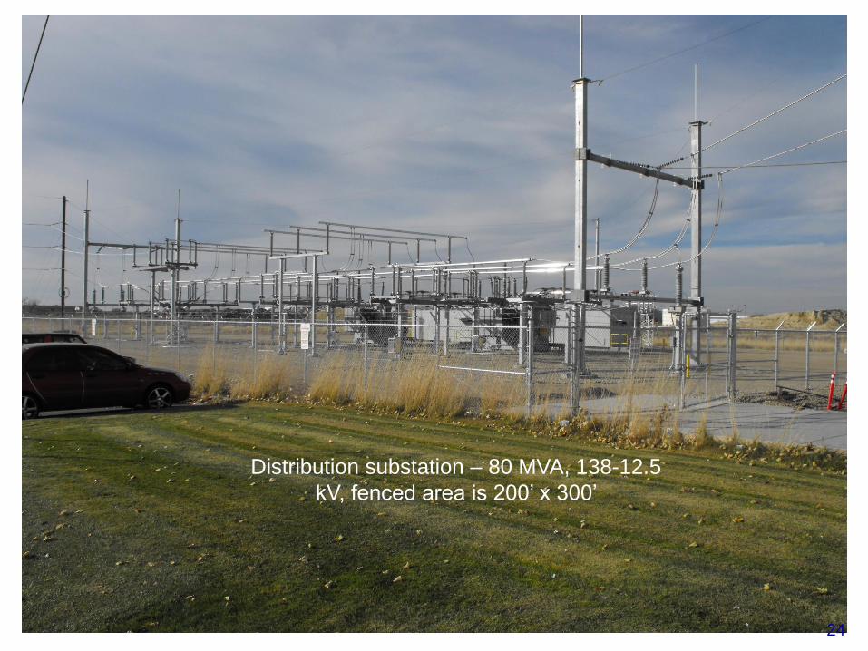
Distribution substation – 80 MVA, 138-12.5
kV, fenced area is 200’ x 300’
24
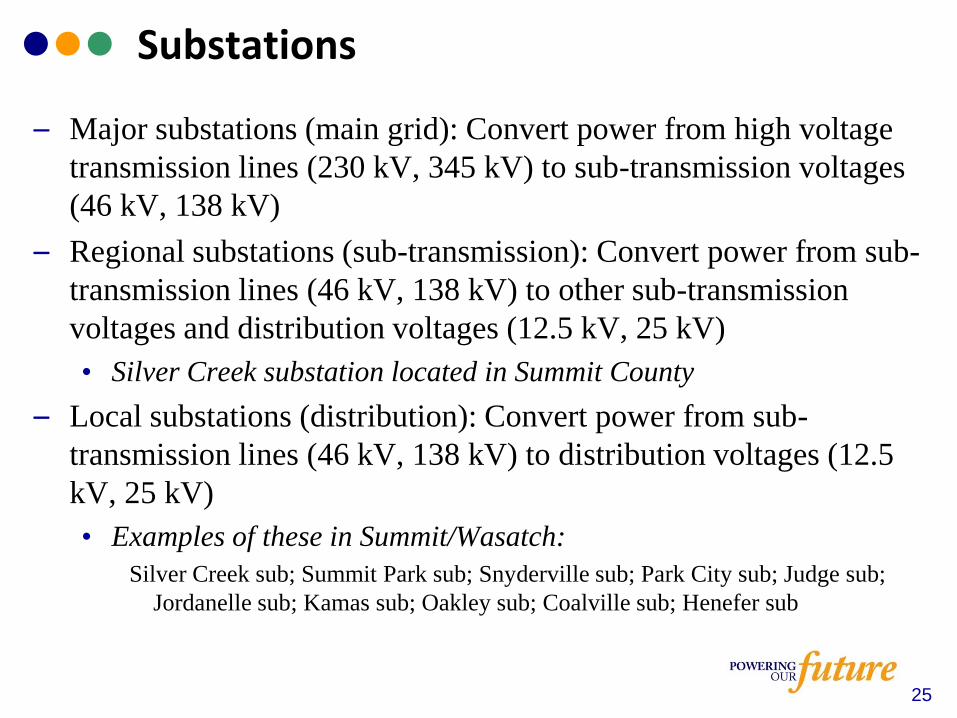
– Major substations (main grid): Convert power from high voltage
transmission lines (230 kV, 345 kV) to sub-transmission voltages
(46 kV, 138 kV)
– Regional substations (sub-transmission): Convert power from sub-
transmission lines (46 kV, 138 kV) to other sub-transmission
voltages and distribution voltages (12.5 kV, 25 kV)
• Silver Creek substation located in Summit County
– Local substations (distribution): Convert power from sub-
transmission lines (46 kV, 138 kV) to distribution voltages (12.5
kV, 25 kV)
• Examples of these in Summit/Wasatch:
Silver Creek sub; Summit Park sub; Snyderville sub; Park City sub; Judge sub;
Jordanelle sub; Kamas sub; Oakley sub; Coalville sub; Henefer sub
25
Substations
– Think of a major (main grid) substation as an on-ramp or off-
ramp from an interstate
– Think of a regional (sub-transmission) substation as an
intersection connecting a state highway to a main city street.
– Think of a local (distribution) substation as an intersection
connecting a main city street to a residential or commercial
subdivision.
– The different types of substations can be co-located.
26
Substations – Highway Analogy

– Using the highway analogy, electricity travels through lines and substations in the same way a commuter might go home from work.
First the commuter leaves the interstate by way of an off-ramp or high voltage substation.
Then high voltage moves down a smaller state highway, leaving the highway at a major intersection or local sub-transmission substation onto a city street.
Next it turns off the city street via a minor intersection or distribution substation into a subdivision.
Finally the commuter turns into the driveway via a pole or pad mount transformer.
27
Substations - Highway Analogy
– Balance Reliability and Cost
– Location considerations
• Central to the area to be served for local distribution
substations
o Most flexibility to recover from outages
o Consistent reliability opportunity for all customers
o Creates strongest support for least cost
o Maximizes coverage area
• Sufficient land area
o Typical local distribution substation requires 1 acre inside fence
o Clearances for electrical safety (NESC minimum)
o Access for large equipment
o Room for expansion to ultimate build-out
Local Distribution Substation Design
28
• Sufficient land area (continued)
o Ultimately serves up to 80 MW of load
o 1-3 square miles for industrial load
o 2-5 square miles for commercial load
o 6-8 square miles for typical urban residential load (8000
homes)
• Environmental considerations
o Year-round access
o Soil and site conditions
• Proximity to existing electrical infrastructure
o Transmission corridors
o Existing distribution facilities
29
Local Distribution Substation Design
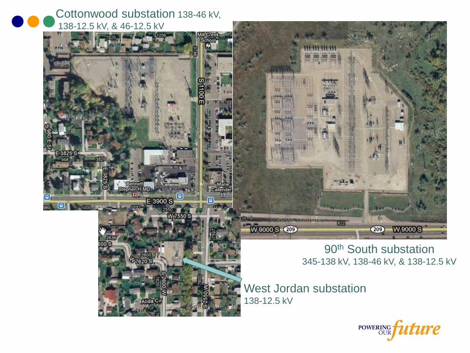
90th South substation345-138 kV, 138-46 kV, & 138-12.5 kV
West Jordan substation138-12.5 kV
Cottonwood substation 138-46 kV,
138-12.5 kV, & 46-12.5 kV
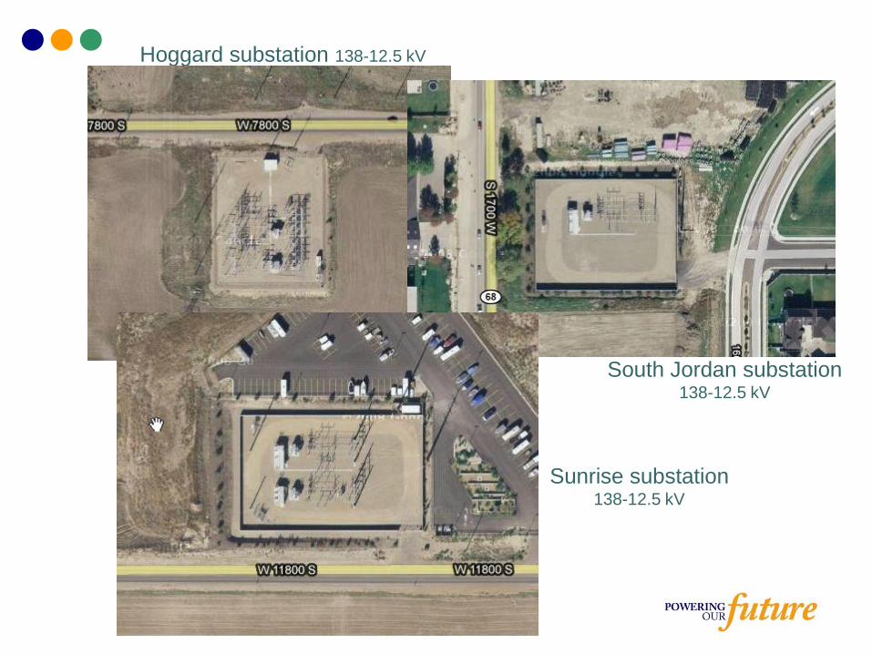
South Jordan substation138-12.5 kV
Sunrise substation138-12.5 kV
Hoggard substation 138-12.5 kV