sitrans library for s7-300 - support.industry.siemens.com · sitrans library for s7-300 function...
TRANSCRIPT
SITRANS Library for S7-300
Function Manual
02/2018A5E35351982-02
Functions of the faceplates 1
Panel blocks, general 2Configurable response using the Feature I/O 3
SITRANS FC430 4
SITRANS LR PA 5
SITRANS P PA 6
SITRANS P 7
SITRANS F M MAG 6000 8
SIPART PS2 9
SITRANS LR HART 10
Driver blocks 11
Legal informationWarning notice system
This manual contains notices you have to observe in order to ensure your personal safety, as well as to prevent damage to property. The notices referring to your personal safety are highlighted in the manual by a safety alert symbol, notices referring only to property damage have no safety alert symbol. These notices shown below are graded according to the degree of danger.
DANGERindicates that death or severe personal injury will result if proper precautions are not taken.
WARNINGindicates that death or severe personal injury may result if proper precautions are not taken.
CAUTIONindicates that minor personal injury can result if proper precautions are not taken.
NOTICEindicates that property damage can result if proper precautions are not taken.If more than one degree of danger is present, the warning notice representing the highest degree of danger will be used. A notice warning of injury to persons with a safety alert symbol may also include a warning relating to property damage.
Qualified PersonnelThe product/system described in this documentation may be operated only by personnel qualified for the specific task in accordance with the relevant documentation, in particular its warning notices and safety instructions. Qualified personnel are those who, based on their training and experience, are capable of identifying risks and avoiding potential hazards when working with these products/systems.
Proper use of Siemens productsNote the following:
WARNINGSiemens products may only be used for the applications described in the catalog and in the relevant technical documentation. If products and components from other manufacturers are used, these must be recommended or approved by Siemens. Proper transport, storage, installation, assembly, commissioning, operation and maintenance are required to ensure that the products operate safely and without any problems. The permissible ambient conditions must be complied with. The information in the relevant documentation must be observed.
TrademarksAll names identified by ® are registered trademarks of Siemens AG. The remaining trademarks in this publication may be trademarks whose use by third parties for their own purposes could violate the rights of the owner.
Disclaimer of LiabilityWe have reviewed the contents of this publication to ensure consistency with the hardware and software described. Since variance cannot be precluded entirely, we cannot guarantee full consistency. However, the information in this publication is reviewed regularly and any necessary corrections are included in subsequent editions.
Siemens AGDivision Process Industries and DrivesPostfach 48 4890026 NÜRNBERGGERMANY
Document order number: A5E35351982Ⓟ 02/2018 Subject to change
Copyright © Siemens AG 2018.All rights reserved
Table of contents
1 Functions of the faceplates...........................................................................................................................9
1.1 Batch view................................................................................................................................9
1.2 Alarm view..............................................................................................................................10
1.3 Trend view..............................................................................................................................11
2 Panel blocks, general.................................................................................................................................13
2.1 Messaging..............................................................................................................................14
2.2 Operating philosophy for operator panel (OP) and operator station (OS)..............................17
2.3 Operator control and monitoring with WinCC flexible............................................................17
2.4 Operator control and monitoring with WinCC (PCS 7 OS).....................................................21
3 Configurable response using the Feature I/O.............................................................................................23
3.1 Configurable functions using the Feature I/O.........................................................................23
3.2 Setting the startup characteristics..........................................................................................24
3.3 Reaction to the out of service mode.......................................................................................25
3.4 Resetting the commands for changing the mode...................................................................26
3.5 Enabling resetting of commands for the control settings.......................................................26
3.6 Set switch or button mode......................................................................................................27
3.7 Read configuration data automatically...................................................................................28
3.8 Exiting local mode..................................................................................................................28
3.9 Resetting via input signals in the event of interlocking (Protection) or errors........................29
3.10 Pause dosing at flow alarm....................................................................................................29
3.11 Activating bumpless changeover to automatic mode.............................................................30
3.12 Update acknowledgment and error status of the message call.............................................30
3.13 Enabling local operating permission......................................................................................30
3.14 Suppression of all messages.................................................................................................31
3.15 Disabling operating points......................................................................................................31
3.16 Signaling limit violation...........................................................................................................32
3.17 Resetting depending on the operating mode.........................................................................32
3.18 Activating reset of protection / errors in manual mode...........................................................33
4 SITRANS FC430........................................................................................................................................35
4.1 S7SiFC43...............................................................................................................................354.1.1 Description of S7SiFC43........................................................................................................354.1.2 Operating modes of S7SiFC43..............................................................................................41
SITRANS Library for S7-300Function Manual, 02/2018, A5E35351982-02 3
4.1.3 Functions of S7SiFC43..........................................................................................................434.1.4 Error handling of S7SiFC43...................................................................................................494.1.5 S7SiFC43 messages.............................................................................................................504.1.6 I/Os of S7SiFC43...................................................................................................................534.1.7 Block diagram of S7SiFC43...................................................................................................734.1.8 Template of S7SiFC43...........................................................................................................734.1.9 Operator control and monitoring............................................................................................744.1.9.1 S7SiFC43 views.....................................................................................................................744.1.9.2 Standard view of S7SiFC43...................................................................................................744.1.9.3 Limit view of S7SiFC43..........................................................................................................804.1.9.4 Parameter view of S7SiFC43.................................................................................................854.1.9.5 Preview of S7SiFC43.............................................................................................................874.1.9.6 Dosing view of S7SiFC43......................................................................................................924.1.9.7 Block icon for S7SiFC43........................................................................................................94
4.2 SiFC43Dr...............................................................................................................................964.2.1 Description of SiFC43Dr........................................................................................................964.2.2 Operating modes of SiFC43Dr...............................................................................................974.2.3 I/Os of SiFC43Dr....................................................................................................................974.2.4 Block diagram of SiFC43Dr..................................................................................................1034.2.5 Template of SiFC43Dr.........................................................................................................1034.2.6 Operator control & monitoring SiFC43Dr.............................................................................103
5 SITRANS LR PA.......................................................................................................................................105
5.1 S7SiLRPA............................................................................................................................1055.1.1 Description of S7SiLRPA.....................................................................................................1055.1.2 Operating modes of S7SiLRPA............................................................................................1085.1.3 Functions of S7SiLRPA........................................................................................................1085.1.4 Error handling of S7SiLRPA.................................................................................................1135.1.5 S7SiLRPA messaging..........................................................................................................1135.1.6 I/Os of S7SiLRPA ................................................................................................................1165.1.7 Block diagram of S7SiLRPA................................................................................................1225.1.8 Template of S7SiLRPA........................................................................................................1235.1.9 Operator control & monitoring..............................................................................................1245.1.9.1 Views of S7SiLRPA..............................................................................................................1245.1.9.2 Standard view of S7SiLRPA................................................................................................1255.1.9.3 Limit view of S7SiLRPA.......................................................................................................1285.1.9.4 Parameter view of S7SiLRPA .............................................................................................1305.1.9.5 Preview of S7SiLRPA..........................................................................................................1315.1.9.6 Block icons for S7SiLRPA ...................................................................................................132
6 SITRANS P PA.........................................................................................................................................133
6.1 S7SiP_PA.............................................................................................................................1336.1.1 Description of S7SiP_PA......................................................................................................1336.1.2 Operating modes of S7SiP_PA............................................................................................1366.1.3 S7SiP_PA functions.............................................................................................................1376.1.4 Error handling of S7SiP_PA.................................................................................................1436.1.5 S7SiP_PA messages...........................................................................................................1446.1.6 I/Os of S7SiP_PA.................................................................................................................1466.1.7 Block diagram of S7SiP_PA.................................................................................................1556.1.8 Template of S7SiP_PA.........................................................................................................1556.1.9 Operator control & monitoring..............................................................................................1566.1.9.1 Views of S7SiP_PA..............................................................................................................156
Table of contents
SITRANS Library for S7-3004 Function Manual, 02/2018, A5E35351982-02

6.1.9.2 Standard view of S7SiP_PA.................................................................................................1576.1.9.3 Limit view of S7SiP_PA........................................................................................................1606.1.9.4 Parameter view of S7SiP_PA...............................................................................................1626.1.9.5 Preview of S7SiP_PA...........................................................................................................1636.1.9.6 Min/min/max pointer view of S7SiP_PA (resettable) ...........................................................1656.1.9.7 Block icon for S7SiP_PA......................................................................................................166
7 SITRANS P...............................................................................................................................................167
7.1 S7SitPHA.............................................................................................................................1677.1.1 Description of S7SitPHA......................................................................................................1677.1.2 Operating modes of S7SitPHA.............................................................................................1717.1.3 Functions of S7SitPHA.........................................................................................................1717.1.4 Error handling of S7SitPHA..................................................................................................1777.1.5 Message behavior of S7SitPHA...........................................................................................1787.1.6 I/Os of S7SitPHA..................................................................................................................1817.1.7 Block diagram of S7SitPHA.................................................................................................1927.1.8 Template of S7SitPHA.........................................................................................................1927.1.9 Operator control & monitoring..............................................................................................1937.1.9.1 Views of S7SitPHA...............................................................................................................1937.1.9.2 Standard view of S7SitPHA.................................................................................................1947.1.9.3 Limit view of S7SitPHA........................................................................................................1967.1.9.4 Parameter view of S7SitPHA...............................................................................................1997.1.9.5 Preview of S7SitPHA...........................................................................................................2007.1.9.6 Slave pointer view of S7SitPHA (resettable) .......................................................................2017.1.9.7 Block icon for S7SitPHA.......................................................................................................203
8 SITRANS F M MAG 6000.........................................................................................................................205
8.1 S7Mag6T..............................................................................................................................2058.1.1 Description of S7Mag6T.......................................................................................................2058.1.2 Operating modes of S7Mag6T.............................................................................................2108.1.3 Functions of S7Mag6T.........................................................................................................2118.1.4 S7Mag6T totalizer functions.................................................................................................2178.1.5 S7Mag6T dosing unit functions............................................................................................2188.1.6 Error handling of S7Mag6T..................................................................................................2218.1.7 S7Mag6T messaging...........................................................................................................2238.1.8 S7Mag6T connections.........................................................................................................2258.1.9 Block diagram of S7Mag6T..................................................................................................2388.1.10 Template of S7Mag6T..........................................................................................................2398.1.11 Operator control and monitoring..........................................................................................2418.1.11.1 S7Mag6T views....................................................................................................................2418.1.11.2 Standard view of S7Mag6T..................................................................................................2418.1.11.3 Limit view of S7Mag6T.........................................................................................................2468.1.11.4 Parameter view of S7Mag6T................................................................................................2488.1.11.5 S7Mag6T preview................................................................................................................2498.1.11.6 S7Mag6T dosing view..........................................................................................................2528.1.11.7 Block icon for S7Mag6T.......................................................................................................254
8.2 S7PMag6T ..........................................................................................................................2568.2.1 Description of S7PMag6T....................................................................................................2568.2.2 S7PMag6T connections.......................................................................................................2578.2.3 Operator Control and Monitoring WinCC.............................................................................2618.2.4 Operator Control and Monitoring WinCC flexible.................................................................2618.2.4.1 Views....................................................................................................................................261
Table of contents
SITRANS Library for S7-300Function Manual, 02/2018, A5E35351982-02 5
8.2.4.2 Standard view of S7Mag6T..................................................................................................2628.2.4.3 S7PMag6T block icon..........................................................................................................263
8.3 FbMag6T..............................................................................................................................2638.3.1 Description of FbMag6T.......................................................................................................2638.3.2 Operating modes for FbMag6T............................................................................................2668.3.3 Functions of FbMag6T.........................................................................................................2668.3.4 Error handling of FbMag6T..................................................................................................2678.3.5 Messaging of FbMag6T.......................................................................................................2678.3.6 I/Os of FbMag6T..................................................................................................................2688.3.7 Block diagram of FbMag6T..................................................................................................270
9 SIPART PS2.............................................................................................................................................271
9.1 S7SipPS2.............................................................................................................................2719.1.1 Description of S7SipPS2......................................................................................................2719.1.2 Operating modes of S7SipPS2............................................................................................2779.1.3 Functions of S7SipPS2 .......................................................................................................2789.1.4 Error handling of S7SipPS2 ................................................................................................2909.1.5 S7SipPS2 messaging .........................................................................................................2919.1.6 S7SipPS2 connections ........................................................................................................2929.1.7 Template of S7SipPS2.........................................................................................................3049.1.8 Operator control & monitoring..............................................................................................3059.1.8.1 Views of S7SipPS2..............................................................................................................3059.1.8.2 Standard view of S7SipPS2.................................................................................................3059.1.8.3 Limit view of S7SipPS2........................................................................................................3109.1.8.4 Parameter view of S7SipPS2...............................................................................................3139.1.8.5 Preview of S7SipPS2...........................................................................................................3159.1.8.6 S7SipPS2 block icon............................................................................................................317
10 SITRANS LR HART..................................................................................................................................319
10.1 S7SiLRHA............................................................................................................................31910.1.1 Description of S7SiLRHA.....................................................................................................31910.1.2 Operating modes of S7SiLRHA...........................................................................................32210.1.3 Functions of S7SiLRHA.......................................................................................................32210.1.4 Error handling of S7SiLRHA................................................................................................32710.1.5 Messages of S7SiLRHA.......................................................................................................32810.1.6 I/Os of S7SiLRHA................................................................................................................33010.1.7 Block diagram of S7SiLRHA................................................................................................33610.1.8 Template of S7SiLRHA........................................................................................................33610.1.9 Operator control & monitoring..............................................................................................33710.1.9.1 Views of S7SiLRHA.............................................................................................................33710.1.9.2 Standard view of S7SiLRHA................................................................................................33810.1.9.3 Limit view of S7SiLRHA.......................................................................................................34110.1.9.4 Parameter view of S7SiLRHA..............................................................................................34210.1.9.5 Preview of S7SiLRHA..........................................................................................................34310.1.9.6 Block icons for S7SiLRHA....................................................................................................344
11 Driver blocks.............................................................................................................................................345
11.1 PiDr64..................................................................................................................................34511.1.1 Description of PiDr64...........................................................................................................34511.1.2 Operating modes PiDr64......................................................................................................34611.1.3 Functions of PiDr64..............................................................................................................34611.1.4 Error handling of PiDr64.......................................................................................................348
Table of contents
SITRANS Library for S7-3006 Function Manual, 02/2018, A5E35351982-02

11.1.5 PiDr64 messaging................................................................................................................34811.1.6 PiDr64 connections..............................................................................................................34811.1.7 Block diagram of PiDr64......................................................................................................350
11.2 PiEl64...................................................................................................................................35011.2.1 Description of PiEl64............................................................................................................35011.2.2 Operating modes of PiEl64..................................................................................................35211.2.3 Functions of PiEl64..............................................................................................................35211.2.4 Error handling of PiEl64.......................................................................................................35211.2.5 PiEl64 messaging................................................................................................................35311.2.6 PiEl64 connections...............................................................................................................35311.2.7 Block diagram of PiEl64.......................................................................................................355
11.3 PiStAr64...............................................................................................................................35511.3.1 Description of PiStAr64........................................................................................................35511.3.2 Operating modes of PiStAr64..............................................................................................35711.3.3 Functions of PiStAr64..........................................................................................................35711.3.4 Error handling of PiStAr64...................................................................................................35711.3.5 PiStAr64 messaging.............................................................................................................35811.3.6 PiStAr64 connections...........................................................................................................35811.3.7 Block diagram of PiStAr64...................................................................................................360
Index.........................................................................................................................................................361
Table of contents
SITRANS Library for S7-300Function Manual, 02/2018, A5E35351982-02 7

Table of contents
SITRANS Library for S7-3008 Function Manual, 02/2018, A5E35351982-02

Functions of the faceplates 11.1 Batch view
Batch view This area shows a display of the batch that is currently running (Batchview).
You can use the internal tag "@APLBatchEnable" to enable/disable the "Batch" button in the toolbar.
Value of @APLBatchEnable Operating the "Batch" button in the toolbar
Icon of the "Batch" button in the toolbar
0 Disabled
1 Enabled
(1) "Enabled"This area shows you if the block is enabled for operation via SIMATIC BATCH (BatchEn = 1).
(2) "Allocated"This area shows if the block is currently in use by SIMATIC BATCH (Occupied = 1).
(3) "Batch name"This area shows the name of the batch that is currently running (Batchname).
(4) "Batch ID"This area shows the identification number of the batch that is currently running (BatchID).
The batch view is disabled if BatchID = 16#00000000.
SITRANS Library for S7-300Function Manual, 02/2018, A5E35351982-02 9
(5) "Batch step"This area shows the step number of the batch that is currently running (StepNo).
1.2 Alarm view
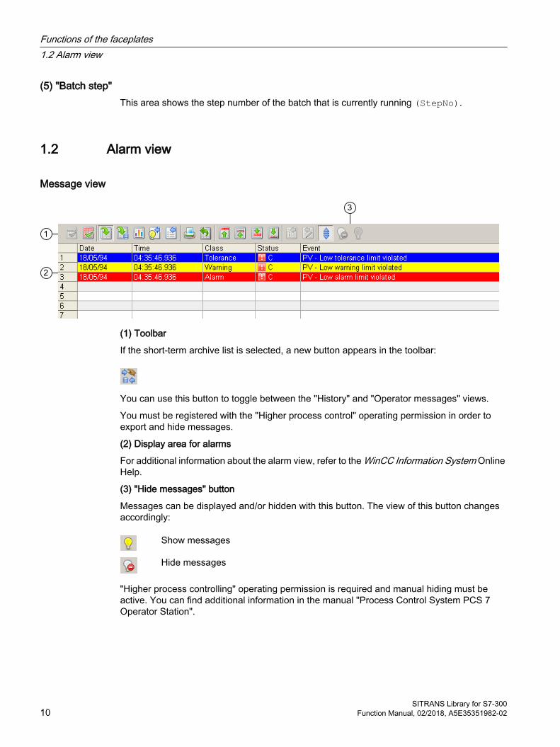
Message view
(1) Toolbar
If the short-term archive list is selected, a new button appears in the toolbar:
You can use this button to toggle between the "History" and "Operator messages" views.
You must be registered with the "Higher process control" operating permission in order to export and hide messages.
(2) Display area for alarms
For additional information about the alarm view, refer to the WinCC Information System Online Help.
(3) "Hide messages" button
Messages can be displayed and/or hidden with this button. The view of this button changes accordingly:
Show messages
Hide messages
"Higher process controlling" operating permission is required and manual hiding must be active. You can find additional information in the manual "Process Control System PCS 7 Operator Station".
Functions of the faceplates1.2 Alarm view
SITRANS Library for S7-30010 Function Manual, 02/2018, A5E35351982-02

1.3 Trend view
Trend view
(1) Toolbar
(2) Display area for trends
(3) Status bar
(4) Button for switching between archive tags and online tags. The status bar shows if the trend view is working with online data or archive data.
(5) Button for opening the "Scatter plot" window
The Export button is only visible and operable with the "Higher-level process control" operating permission.
For additional information about the trend view, refer to the WinCC Information System Online Help.
Functions of the faceplates1.3 Trend view
SITRANS Library for S7-300Function Manual, 02/2018, A5E35351982-02 11
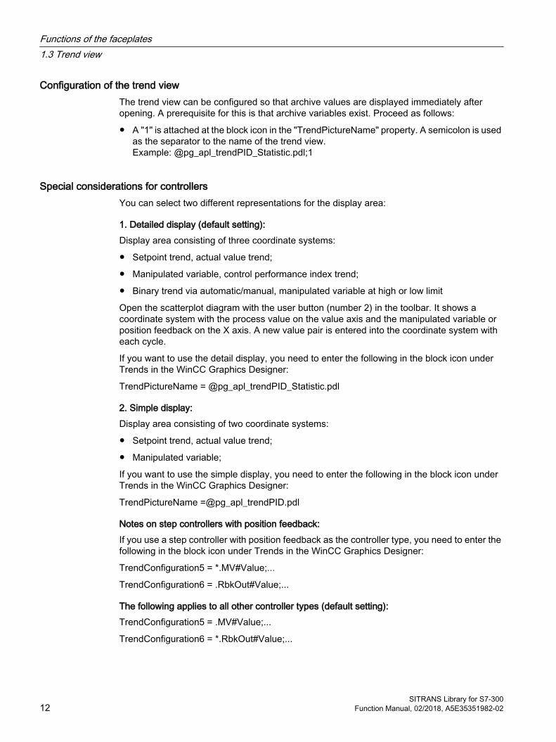
Configuration of the trend viewThe trend view can be configured so that archive values are displayed immediately after opening. A prerequisite for this is that archive variables exist. Proceed as follows:
● A "1" is attached at the block icon in the "TrendPictureName" property. A semicolon is used as the separator to the name of the trend view. Example: @pg_apl_trendPID_Statistic.pdl;1
Special considerations for controllersYou can select two different representations for the display area:
1. Detailed display (default setting):Display area consisting of three coordinate systems:
● Setpoint trend, actual value trend;
● Manipulated variable, control performance index trend;
● Binary trend via automatic/manual, manipulated variable at high or low limit
Open the scatterplot diagram with the user button (number 2) in the toolbar. It shows a coordinate system with the process value on the value axis and the manipulated variable or position feedback on the X axis. A new value pair is entered into the coordinate system with each cycle.
If you want to use the detail display, you need to enter the following in the block icon under Trends in the WinCC Graphics Designer:
TrendPictureName = @pg_apl_trendPID_Statistic.pdl
2. Simple display:Display area consisting of two coordinate systems:
● Setpoint trend, actual value trend;
● Manipulated variable;
If you want to use the simple display, you need to enter the following in the block icon under Trends in the WinCC Graphics Designer:
TrendPictureName =@pg_apl_trendPID.pdl
Notes on step controllers with position feedback:If you use a step controller with position feedback as the controller type, you need to enter the following in the block icon under Trends in the WinCC Graphics Designer:
TrendConfiguration5 = *.MV#Value;...
TrendConfiguration6 = .RbkOut#Value;...
The following applies to all other controller types (default setting):TrendConfiguration5 = .MV#Value;...
TrendConfiguration6 = *.RbkOut#Value;...
Functions of the faceplates1.3 Trend view
SITRANS Library for S7-30012 Function Manual, 02/2018, A5E35351982-02
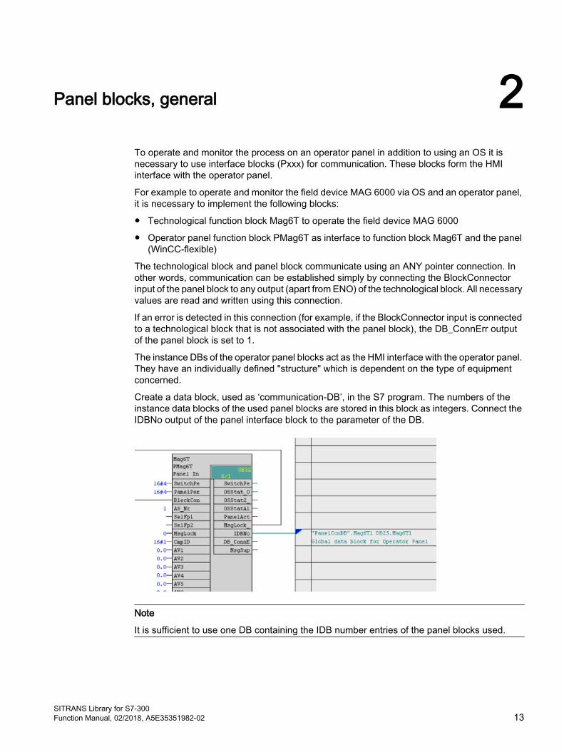
Panel blocks, general 2To operate and monitor the process on an operator panel in addition to using an OS it is necessary to use interface blocks (Pxxx) for communication. These blocks form the HMI interface with the operator panel.
For example to operate and monitor the field device MAG 6000 via OS and an operator panel, it is necessary to implement the following blocks:
● Technological function block Mag6T to operate the field device MAG 6000
● Operator panel function block PMag6T as interface to function block Mag6T and the panel (WinCC-flexible)
The technological block and panel block communicate using an ANY pointer connection. In other words, communication can be established simply by connecting the BlockConnector input of the panel block to any output (apart from ENO) of the technological block. All necessary values are read and written using this connection.
If an error is detected in this connection (for example, if the BlockConnector input is connected to a technological block that is not associated with the panel block), the DB_ConnErr output of the panel block is set to 1.
The instance DBs of the operator panel blocks act as the HMI interface with the operator panel. They have an individually defined "structure" which is dependent on the type of equipment concerned.
Create a data block, used as ‘communication-DB’, in the S7 program. The numbers of the instance data blocks of the used panel blocks are stored in this block as integers. Connect the IDBNo output of the panel interface block to the parameter of the DB.
Note
It is sufficient to use one DB containing the IDB number entries of the panel blocks used.
SITRANS Library for S7-300Function Manual, 02/2018, A5E35351982-02 13

2.1 Messaging
PCS 7 messagingEvery panel function block can generate messages. Messages can be suppressed using the MsgLock parameter.Messages are sent via ALARM_DQ, and those of the technological block are suppressed to avoid duplication. To enable this, the MsgLock input must be set to 0 on the panel block. The output structure MsgLock_Out =1 is set simultaneously, and must be connected to the MsgLock input structure of the technological block.If control system messages (CSF) and external messages (ExtMsgx) are to be suppressed as well, Feature bit 25 (1 = Suppress all messages if MsgLock = 1) must also be set at the technological block.It principally applies that all messages on the technological block are also present on the panel block.
In the message view of the WinCC-flexible faceplate, the message classes "S7 messages", "S7 controller control system messages" and "S7 warning" are displayed. Note that messages
Panel blocks, general2.1 Messaging
SITRANS Library for S7-30014 Function Manual, 02/2018, A5E35351982-02
of the message class "S7 process message" or "S7 tolerance" are not displayed by the system broken down by instances in the message view of the WinCC-flexible faceplate. Messages of these classes must be displayed by a separate message view in the WinCC-flexible project.A separate filter is required for the instance granular view of the messages in the message view of the WinCC-flexible faceplate. This filter consists of the instance DB number of the panel function block and the value configured at the AS_No input of the panel block. The value of the filter is transferred to the panel via the Op_MsgFilter input for filtering. When the ALARM_DQ messages are generated at the panel block, the content of the message filter is added to the message text of the message. The messages can then be filtered on the operator panel using the message filter provided by Op_MsgFilter.An unambiguous value must be configured at the AS_No input for every AS in the project. Values between 1 and 999 are permissible at the AS_No input.
Panel blocks, general2.1 Messaging
SITRANS Library for S7-300Function Manual, 02/2018, A5E35351982-02 15
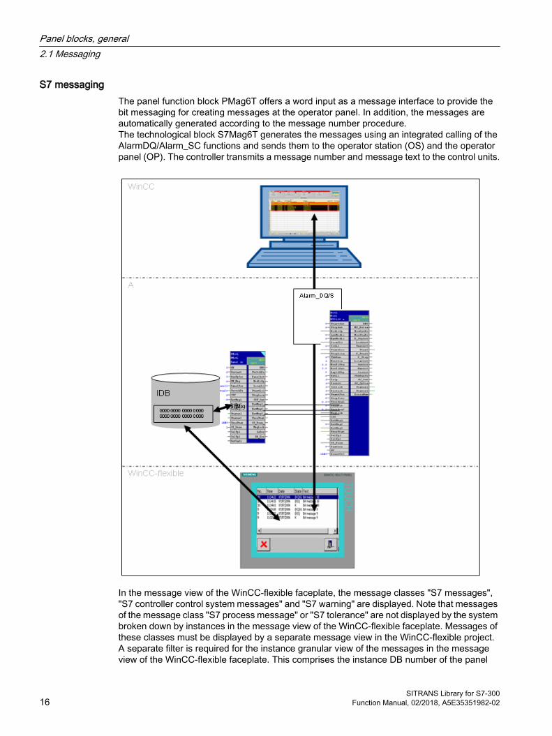
S7 messagingThe panel function block PMag6T offers a word input as a message interface to provide the bit messaging for creating messages at the operator panel. In addition, the messages are automatically generated according to the message number procedure.The technological block S7Mag6T generates the messages using an integrated calling of the AlarmDQ/Alarm_SC functions and sends them to the operator station (OS) and the operator panel (OP). The controller transmits a message number and message text to the control units.
In the message view of the WinCC-flexible faceplate, the message classes "S7 messages", "S7 controller control system messages" and "S7 warning" are displayed. Note that messages of the message class "S7 process message" or "S7 tolerance" are not displayed by the system broken down by instances in the message view of the WinCC-flexible faceplate. Messages of these classes must be displayed by a separate message view in the WinCC-flexible project.A separate filter is required for the instance granular view of the messages in the message view of the WinCC-flexible faceplate. This comprises the instance DB number of the panel
Panel blocks, general2.1 Messaging
SITRANS Library for S7-30016 Function Manual, 02/2018, A5E35351982-02
function block and the value parameterized at the "AS_NR" input of the panel block.The filter value is forwarded to the panel via the "OP_MSG_FILTER" input for filtering and to the technological block via the ANY pointer connection for message generation.When generating the ALARM_DQ messages on the technological block, the content of the message filter is also written into the text of the message.
The messages can then be filtered on the operator panel using the message filter provided by "OP_MSG_FILTER".An unambiguous value must be configured at the "AS_NR" input for every AS in the project. Values between 1 and 999 are permitted at the "AS_NR" input.
2.2 Operating philosophy for operator panel (OP) and operator station (OS)
All operator stations have two standard operating levels, the operating levels 5 and 6. An operator with operating level 5 "Process controlling" can perform all switching operations, i.e. all technological devices can be activated/deactivated or the operating mode can be switched from manual to automatic and vice versa.An operator with operating level 6 "Higher process controlling" can change parameters provided to the operator by a faceplate.
Additional operating level 1100 for PCS 7:An operator with operating level 1100 "Highest process controlling" can simulate process values and release the process tag for maintenance.Only operating level 5 is available on the operator panel. Thus it is not possible to change parameters from the OP or switch to out of service mode.
2.3 Operator control and monitoring with WinCC flexible
IntroductionWith the SITRANS library for WinCC flexible you get pre-configured faceplate blocks. The block icons and faceplates are preconfigured with the necessary variables and functions. When items are inserted into the screen, the variables and connections are generated in addition to the graphic objects. All you have to do is adapt them according to the project-specific conditions. Note that a separate variables container is required for each block icon and each faceplate.You can display the process values of several technological blocks of the same type in one window. To define which process values are to be displayed on the faceplate, click the relevant block icon.
Note
You can enable the Auxiliary Value View using the EnAux input of the panel block.
Panel blocks, general2.3 Operator control and monitoring with WinCC flexible
SITRANS Library for S7-300Function Manual, 02/2018, A5E35351982-02 17

ViewsThe blocks provide the following views:
● Standard view
● Message view (some blocks)
● Trend view (some blocks)
● Associated value view
Trend view
Connect variables for trend view
If the faceplate provides a trend view ( ), you have to connect the variable(s) to be displayed as described (the example shows PMonAn with OpPV view):
Panel blocks, general2.3 Operator control and monitoring with WinCC flexible
SITRANS Library for S7-30018 Function Manual, 02/2018, A5E35351982-02

1. Insert the faceplate-instance into the screen and mark it.
2. Click "Trend" in the "General" area under "Properties".
3. Click the "…" button in the "Trend" line. The dialog for selecting the connectable variables opens.
4. Double-click on the row of the dialog to add a variable. The variable to be displayed can now be configured in the "Source settings" column.
Panel blocks, general2.3 Operator control and monitoring with WinCC flexible
SITRANS Library for S7-300Function Manual, 02/2018, A5E35351982-02 19
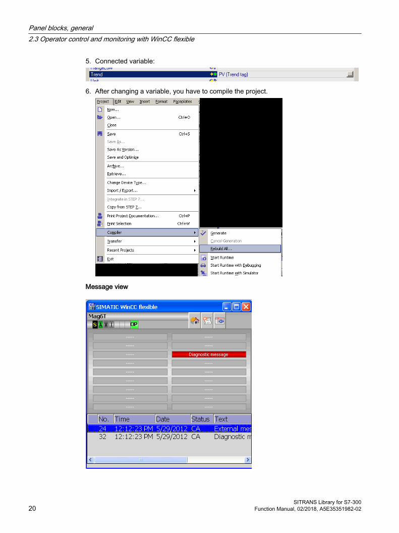
5. Connected variable:
6. After changing a variable, you have to compile the project.
Message view
Panel blocks, general2.3 Operator control and monitoring with WinCC flexible
SITRANS Library for S7-30020 Function Manual, 02/2018, A5E35351982-02
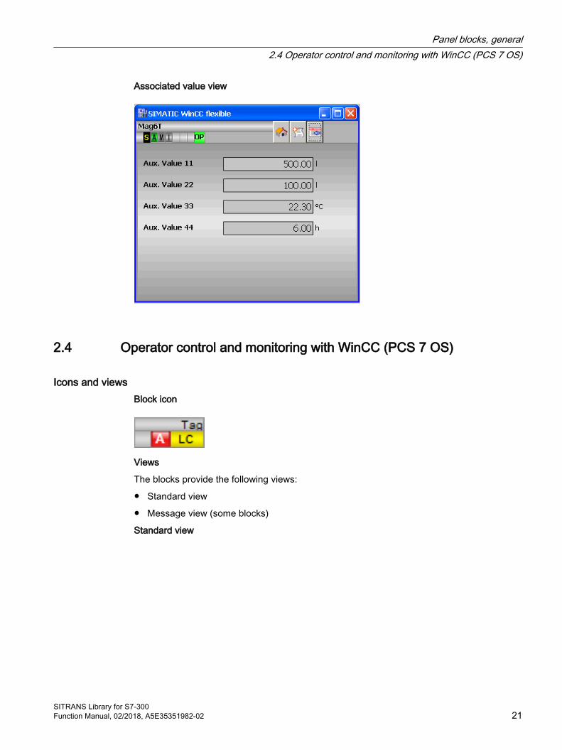
Associated value view
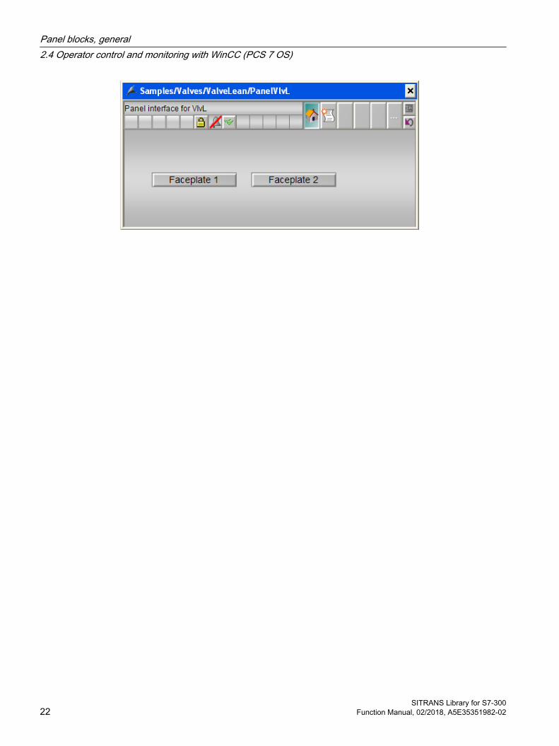
2.4 Operator control and monitoring with WinCC (PCS 7 OS)
Icons and viewsBlock icon
Views
The blocks provide the following views:
● Standard view
● Message view (some blocks)
Standard view
Panel blocks, general2.4 Operator control and monitoring with WinCC (PCS 7 OS)
SITRANS Library for S7-300Function Manual, 02/2018, A5E35351982-02 21
Panel blocks, general2.4 Operator control and monitoring with WinCC (PCS 7 OS)
SITRANS Library for S7-30022 Function Manual, 02/2018, A5E35351982-02
Configurable response using the Feature I/O 33.1 Configurable functions using the Feature I/O
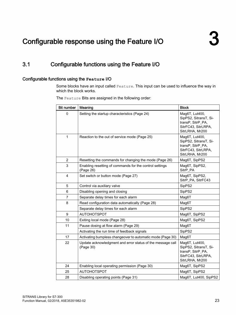
Configurable functions using the Feature I/O Some blocks have an input called Feature. This input can be used to influence the way in which the block works.
The Feature Bits are assigned in the following order:
Bit number Meaning Block0 Setting the startup characteristics (Page 24) Mag6T, Lut400,
SipPS2, SitransT, Si‐transP, SitrP_PA, SitrFC43, SitrLRPA, SitrLRHA, Mr200
1 Reaction to the out of service mode (Page 25) Mag6T, Lut400, SipPS2, SitransT, Si‐transP, SitrP_PA, SitrFC43, SitrLRPA, SitrLRHA, Mr200
2 Resetting the commands for changing the mode (Page 26) Mag6T, SipPS23 Enabling resetting of commands for the control settings
(Page 26) Mag6T, SipPS2, SitrP_PA
4 Set switch or button mode (Page 27) Mag6T, SipPS2, SitrP_PA, SitrFC43
5 Control via auxiliary valve SipPS26 Disabling opening and closing SipPS27 Separate delay times for each alarm Mag6T8 Read configuration data automatically (Page 28) Mag6T
Separate delay times for each alarm SipPS29 AUTOHOTSPOT Mag6T, SipPS210 Exiting local mode (Page 28) Mag6T, SipPS211 Pause dosing at flow alarm (Page 29) Mag6T
Activating the run time of feedback signals SipPS217 Activating bumpless changeover to automatic mode (Page 30) Mag6T22 Update acknowledgment and error status of the message call
(Page 30) Mag6T, Lut400, SipPS2, SitransT, Si‐transP, SitrP_PA, SitrFC43, SitrLRPA, SitrLRHA, Mr200
24 Enabling local operating permission (Page 30) Mag6T, SipPS225 AUTOHOTSPOT Mag6T, SipPS228 Disabling operating points (Page 31) Mag6T, Lut400, SipPS2
SITRANS Library for S7-300Function Manual, 02/2018, A5E35351982-02 23
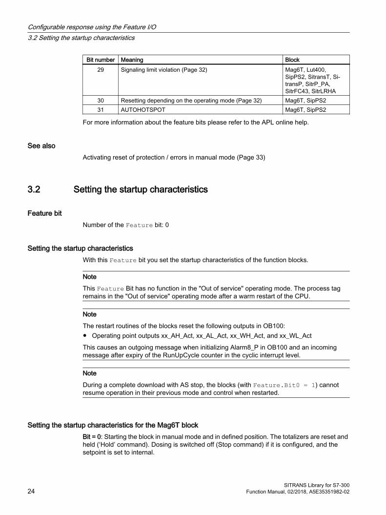
Bit number Meaning Block29 Signaling limit violation (Page 32) Mag6T, Lut400,
SipPS2, SitransT, Si‐transP, SitrP_PA, SitrFC43, SitrLRHA
30 Resetting depending on the operating mode (Page 32) Mag6T, SipPS231 AUTOHOTSPOT Mag6T, SipPS2
For more information about the feature bits please refer to the APL online help.
See alsoActivating reset of protection / errors in manual mode (Page 33)
3.2 Setting the startup characteristics
Feature bitNumber of the Feature bit: 0
Setting the startup characteristics With this Feature bit you set the startup characteristics of the function blocks.
Note
This Feature Bit has no function in the "Out of service" operating mode. The process tag remains in the "Out of service" operating mode after a warm restart of the CPU.
Note
The restart routines of the blocks reset the following outputs in OB100:● Operating point outputs xx_AH_Act, xx_AL_Act, xx_WH_Act, and xx_WL_Act
This causes an outgoing message when initializing Alarm8_P in OB100 and an incoming message after expiry of the RunUpCycle counter in the cyclic interrupt level.
Note
During a complete download with AS stop, the blocks (with Feature.Bit0 = 1) cannot resume operation in their previous mode and control when restarted.
Setting the startup characteristics for the Mag6T blockBit = 0: Starting the block in manual mode and in defined position. The totalizers are reset and held (‘Hold’ command). Dosing is switched off (Stop command) if it is configured, and the setpoint is set to internal.
Configurable response using the Feature I/O3.2 Setting the startup characteristics
SITRANS Library for S7-30024 Function Manual, 02/2018, A5E35351982-02

Bit = 1: The block operates with the last valid commands before CPU-stop, stored at the Oldxxx inputs, for the totalizers and the dosing unit. These inputs can be read back before a complete download.
Setting the startup characteristics for the SitrFC43 blockBit = 0: Starting the block in manual mode and in defined position. The totalizers are held (‘Hold’ command). Dosing is switched off (Stop command) if it is configured, and the setpoint is set to internal.
Bit = 1: The block operates with the last valid commands before CPU-stop, stored at the Oldxxx inputs, for the totalizers and the dosing unit. These inputs can be read back before a complete download.
Setting the startup characteristics for Lut400, SipPS2, SitransT, SitransP, SitrP_PA, SitrLRPA, SitrLRHA and Mr200 blocks
Bit = 0: The most recently stored values are reset on startup
Bit = 1: The most recently used value at the output parameter Out is output on startup.
See alsoDescription of S7Mag6T (Page 205)
3.3 Reaction to the out of service mode
Feature bitNumber of the Feature bit: 1
Reaction to the Out of service modeYou can use this Feature bit to define the response of the technological block depending on the connectable input parameter OosLi = 1 or Oos2Li = 1.
The default setting is 0.
● Bit = 0: The symbol for the "In progress" status (see below) appears in the block icon and in the faceplate of the assigned technologic block. A change 0-1 in the edge of the input parameter OosLi or Oos2Li has no further influence on the response of the technological block, the initial status is retained. No switch to the "Out of service" mode is performed.
● Bit = 1: The mode switches to "Out of service" assuming that the block is "On" or "Manual" mode. If this is not the case, the mode does not change. The symbol for the "In progress" (see below) status also appears in the block icon and in the faceplate of the assigned technologic block regardless of the mode change. No message is output to indicate whether or not the mode change took place.
The status display for "In progress" appears as follows:
Configurable response using the Feature I/O3.3 Reaction to the out of service mode
SITRANS Library for S7-300Function Manual, 02/2018, A5E35351982-02 25

A change 0-1 in the edge of the input parameter OosLi or Oos2Li has no influence on the response of the technological block, the initial status is retained.
3.4 Resetting the commands for changing the mode
Feature BitNumber of the Feature bit: 2
Resetting the commands for changing the modeWith this Feature bit you define how the block handles the incoming control commands DSP_IntLi, DSP_ExtLi (for setpoint of the dosing unit) as well as AutModLi and ManModLi or AutMod2Li and ManMod2Li. The default setting is 0.
Bit = 0: The control commands are not reset by the block. If there are two pending control commands for changing mode, the mode is not changed. In this case, the note text "Invalid command" is displayed in the faceplate.
Bit = 1: The control commands are reset by the block. This, for example, ensures that if a control command is sent from the SFC, the command is reset automatically after a step is exited.
3.5 Enabling resetting of commands for the control settings
Feature BitNumber of the Feature bit: 3
Enabling resetting of commands for the control settingsWith this Feature bit you select how the block handles commands for the control settings (e.g. "totalizer Hold" or "Start dosing") via the interconnected input parameters. The default setting is 0.
Bit = 0: The control commands are not reset by the block. If there are two commands relating to the control settings at the same time, the status of the control settings is retained. In this case, the "Invalid signal" message is displayed in the standard view of the faceplate.
Bit = 1: The control commands are reset by the block. This, for example, ensures that if a control command is sent from the SFC, the command is reset automatically after a step is exited.
Configurable response using the Feature I/O3.5 Enabling resetting of commands for the control settings
SITRANS Library for S7-30026 Function Manual, 02/2018, A5E35351982-02

3.6 Set switch or button mode
Feature bitNumber of the Feature bit: 4
Setting switch or button mode (input signal as pulse signal or as static signal)You can use this Feature bit to select the mode switchover between manual and automatic mode and to determine whether the setpoint is selected with a switch or with two 1-active control inputs (buttons). This Feature bit has no influence on the control commands sent to the module such as e.g. ‘Stop counter’ or ‘Start dosing’.
The Feature bit affects the following control inputs:
● Mode switchover (parameters AutModLi and ManModLi or AutMod2Li and ManMod2Li)
● Internal and external setpoint input of the dosing unit (parameters DSP_ExtLi and DSP_IntLi)
The Feature bit acts on control inputs in the form of a pulse (button mode) or a static signal (switch mode).
You can find the commands for controlling the block in the relevant section on block operating modes. They are always the parameters that are used for the automatic operation of a block.
Bit = 0: Button mode: Each automatic command is assigned to a control input. This has a latching reaction and is 1-active.
Mode:
● AutModLi/AutMod2Li = 1 for setting "Automatic" operating mode
● ManMod1Li/ManMod2Li = 1 for setting "Manual" operating mode
Setpoint selection:
● DSP_ExtLi = 1 to select the external setpoint and
● DSP_IntLi = 1 to select the internal setpoint
Bit = 1: Switching mode: two static automatic commands are assigned to a control input.
Mode:
● AutModLi/AutMod2Li = 1 for setting "Automatic" operating mode
● ManMod1Li/ManMod2Li = 0 for setting "Manual" operating mode
Setpoint selection:
● DSP_ExtLi = 1to select the external setpoint
● DSP_IntLi = 0 to select the internal setpoint
The ManMod1Li/ManMod2Li and DSP_IntLi inputs have no effects.
Configurable response using the Feature I/O3.6 Set switch or button mode
SITRANS Library for S7-300Function Manual, 02/2018, A5E35351982-02 27

3.7 Read configuration data automatically
Feature bitNumber of the Feature bit: 8
Read configuration data automaticallyUsing this Feature bit you define if the configuration data is read out automatically at the restart of the control (OB100) or the re-accessibility of the device via Profibus (OB86, return of the rack).
The configuration may be for example:
● Units
● Scale
● Warning limit, alarm limit, and hysteresis.
● Setpoint and compensation.
Note
The configuration data is read by means of acyclic services. At each Profibus cable only 8 acyclic services can be performed simultaneously. So it is possible that the execution (for example after a return of the Profibus cable) of the data is done with a noticeable delay, if all participants read out their configuration data at the same time. So do not set the Feature bit 8 if more than 8 participants use acyclic services and update the configuration data after a change with the parameter view in the faceplate.
Bit = 0: The configuration data is not read out automatically at restart of the control (OB100) and return of the rack (OB86). Changed data have to be read out using the parameter view in the faceplate.
Bit = 1: The configuration data is read out automatically at restart of the control (OB100) and return of the rack (OB86).
3.8 Exiting local mode
Feature bitNumber of the Feature bit: 10
Reaction to exiting local mode Use this Feature bit to define how the "Local mode" is to be exited with LocalSetting = 1 or LocalSetting = 2 and if the mode is not specified by AutMod1Li or ManMod1Li or AutMod2Li or ManMod2Li.
Default setting is 0
Configurable response using the Feature I/O3.8 Exiting local mode
SITRANS Library for S7-30028 Function Manual, 02/2018, A5E35351982-02
Bit = 0: Exiting local mode in manual mode (bumpless because the control signals are continuously adjusted).
Bit = 1: When local mode is exited, the mode changes back to the last mode that was active prior to local mode (not bumpless).
For more detailed information, refer to the description of Local mode of the Standard APL blocks.
3.9 Resetting via input signals in the event of interlocking (Protection) or errors
Feature BitNumber of the Feature bit: 9
Resetting the block in the event of interlocking (only Protection: Input parameter Protect) or errors via input signals
With this Feature bit, you define how automatic control is to be re-enabled after an active interlock.
The default setting is 0.
Bit = 0: After an interlock (only Protection: Input parameter Protect) or errors, the system can only be restarted using a reset command. Reset is initiated either by operator input in the faceplate or via the interconnectable input parameter (RstLi = 1) in the block. Thereafter, the currently pending command takes effect in automatic mode.
Bit = 1: It is also possible to reset with a 0-1 edge change in the control signal in automatic mode.
3.10 Pause dosing at flow alarm
Feature bitNumber of the Feature bit: 11
Pause in dosing in the event of a flow alarm With this Feature bit you enable pausing at a flow alarm.
Default setting is 0
Bit = 0: Disabled, dosing is not paused when a flow alarm occurs.
Bit = 1: Enabled, dosing is changed to “Pause dosing” when a flow alarm occurs.
Configurable response using the Feature I/O3.10 Pause dosing at flow alarm
SITRANS Library for S7-300Function Manual, 02/2018, A5E35351982-02 29

3.11 Activating bumpless changeover to automatic mode
Feature bitNumber of the Feature bit: 17
Bumpless switchoverYou can use this Feature bit to enable the bumpless switchover from local/manual mode to automatic mode.
Default setting is 0
Bit = 0: Bumpless switchover is disabled. You can switch from local/manual mode to automatic mode at any time.
Bit = 1: Bumpless switchover from local/manual mode to automatic mode is enabled. A switchover from local/manual mode to automatic mode is only possible if the control settings of the local/manual mode and automatic modes match. If switchover occurs at a different point in time, this is indicated in the faceplate with the text "Switchover error".
3.12 Update acknowledgment and error status of the message call
Feature bitNumber of the Feature bit: 22
Update acknowledgment and error status of the message callYou can use the Feature bit to determine if the acknowledgment and error status of the message call at the block output should be updated.
The default setting is 0.
● Bit = 0:The MsgErr1/2/3, MsgStat1/2/3 and MsgAckn1/2/3 block outputs are set to the default setting and not updated. The block will run faster with this setting.
● Bit = 1: The block outputs MsgErr1/2/3, MsgStat1/2/3 and MsgAckn1/2/3 are updated using the feedback messages of the subordinate message blocks. The subordinate message blocks are called in every 2nd cycle if an acknowledgment is waited for or if error information is present.
3.13 Enabling local operating permission
Feature bitNumber of the Feature bit: 24
Configurable response using the Feature I/O3.13 Enabling local operating permission
SITRANS Library for S7-30030 Function Manual, 02/2018, A5E35351982-02
Enabling local operator authorizationYou can use this Feature bit to enable local permission for a technologic block. Local operator authorization is an upstream operator control permission which is determined before the operator authorizations for user management and the release of the block, and is realized via the Standard APL-block OpStations block. Details can be found in the APL Online Help of the OpStations block.
If local operator authorization is missing, operation of a block instance on an OS is usually blocked. Otherwise, when local operator authorization is allowed, the operator control permission is normally determined through user management and the block.
Local operating permission can be set for each specific instance; in other words, block instances can be enabled or disabled for use on an operator station independently of one another.
The default setting is 0.
Bit = 0: Disabled
Bit = 1: Enabled
3.14 Suppression of all messages
Feature BitNumber of the Feature bit: 25
Suppression of all messagesYou can use this Feature bit to determine whether all messages of the block are to be suppressed.
Bit = 0: Process messages are suppressed.
Bit = 1: All messages are suppressed.
3.15 Disabling operating points
Feature bitNumber of the Feature bit: 28
Disabling operating pointsYou can use this Feature bit to define whether the operating point functionality (xx_Ax_Act/xx_Wx_Act outputs) of a limit are also to be deactivated when the message (MsgLock = 1) is deactivated.
The default setting is 0.
Configurable response using the Feature I/O3.15 Disabling operating points
SITRANS Library for S7-300Function Manual, 02/2018, A5E35351982-02 31

Bit = 0: Operating point is not suppressed
Bit = 1: Operating point is suppressed
3.16 Signaling limit violation
Feature bitNumber of the Feature bit: 29
Signaling limit violationWith this Feature bit, you specify how limit violation should be sent to the respective limit outputs. This concerns the outputs for the limits of the volume flow (VF_AH_Act, VF_WH_Act, VF_WL_Act, VF_AL_Act) and the totalizers 1 or 2 (Tot1_AH_Act, Tot1_WH_Act, Tot1_VF_WL_Act, Tot1_AL_Act or Tot2_AH_Act, Tot2_WH_Act, Tot2_VF_WL_Act, Tot2_AL_Act)
The default setting is 0.
Bit = 0: Output value of the limit output = 1 (1 active)
Bit = 1: Output value of the limit output = 0 (0 active)
3.17 Resetting depending on the operating mode
Feature bitNumber of the Feature bit: 30
Resetting depending on the operating modeWhen the "Protection" interlock, feedback error ("Runtime error", "Control error") or "Motor protection" signal is present again, use this Feature bit to specify if a reset can be made depending on the mode only by the operator in manual mode or only by the automatic I/Os in automatic mode.
Resetting to manual mode is enabled with Feature Bit 31 (Activating reset of protection / errors in manual mode (Page 33)). Also refer to the "Resetting the block in case of interlocks or errors" section of the manual of the Standard APL blocks.
The default setting is 0.
Bit = 0: Resetting is independent of the operating mode
Bit = 1: In manual mode, manual resetting by the operator is only possible if Feature bit 31 is set, otherwise resetting is not required in manual mode.
Configurable response using the Feature I/O3.17 Resetting depending on the operating mode
SITRANS Library for S7-30032 Function Manual, 02/2018, A5E35351982-02
In automatic mode, only resetting via automatic connections is possible, regardless of Feature bit 31. This is carried out by a 0-1 change in edge at the RstLi input or - with the Feature bit 9 set - by a 0-1 change in edge at the automatic inputs e.g. DSrtAut.
3.18 Activating reset of protection / errors in manual mode
Feature bitNumber of the Feature bit: 31
Activating reset of protection / errors in manual modeUse this Feature bit to specify whether a reset is necessary once the "Protection" interlock signal is present again. Also refer to the "Resetting the block in case of interlocks or errors" section of the manual of the Standard APL blocks.
The default setting is 0.
Bit = 0: No resetting necessary in manual mode.
Bit = 1: Resetting is necessary in manual mode. The reset is performed using the "Reset" button (RstOp = 1) or, in CFC, using the input parameter RstLi.
Configurable response using the Feature I/O3.18 Activating reset of protection / errors in manual mode
SITRANS Library for S7-300Function Manual, 02/2018, A5E35351982-02 33

Configurable response using the Feature I/O3.18 Activating reset of protection / errors in manual mode
SITRANS Library for S7-30034 Function Manual, 02/2018, A5E35351982-02
SITRANS FC430 44.1 S7SiFC43
4.1.1 Description of S7SiFC43
Object name (type + number) and familyType + number: FB 2639
Family: Sitrans
Area of application for S7SiFC43 The block is used for the following application:
● Interface block between the driver blocks of the HART module SITRANS FC430 (referred to below as FC430) for the user program and visualization.
How it works The S7SiFC430 block prepares the process data received by driver blocks from a FC430 and makes the data available for further use in the user program and for visualization. Data entered in the faceplate or via the block inputs is transferred to the FC430 by means of driver blocks and the SiFC43Dr block (FB2631).
The function block supports all PDM configurations of the max. four HART auxiliary variables of the FC430.
Note
Below, block parameters are identified e.g. by PV/SV/TV/QV_OpScaleH, PV/SV/TV/QV_OpScaleL where the PV_OpScaleH/L, SV_OpScaleH/L, TV_OpScaleH/L and QV_OpScaleH/L inputs are intended for the HART variables PV, SV, TV and QV.
Configuration In the CFC editor, install the block in a cyclic interrupt OB (OB30 to OB38). The block is also installed automatically in the startup OB (OB 100). Moreover, to connect the I/O signals, it is imperative to call the driver block PiDr64 (acyclic data) in the same interrupt OB and startup OB (OB100) before the S7SiFC43 block in each case. The output structure AcyclData of the PiDr64 block is interconnected to the input with the same name of the SiFC43Dr block. The SxRdReq, SxWrReq and Para output structures of the SiFC43Dr block are interconnected to the RdReq, WrReq and Para inputs of the S7SiFC43 block. The SiFC43Dr block must be called after the PiDr64 and before the S7SiFC43 block.
SITRANS Library for S7-300Function Manual, 02/2018, A5E35351982-02 35
Feature Bit 7 = TRUE means that the block takes over the message limits when reading the configuration data from the device. The maximum and minimum values for the alarm and warning limits of the process values are configured at the LimPV/SV/TV/QV_OpScaleH, LimPV/SV/TV/QV_OpScaleL inputs, or read out from the device if Feature bit 7 is set for synchronization of the message configuration with the device.
Measuring ranges of the corresponding measured values are configured at the PV/SV/TV/QV_OpScaleH, LimPV/SV/TV/QV_OpScaleL inputs.
Dosing function
If dosing is used, the following must be configured:
1. Configuration of a dosing mode in PDM
2. Setting of Feature bit 14 (activate dosing) to TRUE
3. Supply of SV input with the current dosing quantity via a 4 to 20 mA input
4. Supply of FbkDosVlv input with the current feedback of the dosing valve via a digital input
Note
The dosing valve requires a binary feedback of its current state. The feedback of the dosing valve must be interconnected to the FbkDosVlv input so that the new dosing state is read out by means of acyclic communication in the event of a change. Start of dosing is also transmitted to the device by means of acyclic communication. Since, in contrast to cyclic data transmission, this can take several cycles, the FC430 is not suitable for applications in which dosing operations have to be started in rapid succession.
Note
The S7SiFC43 block contains two templates for process tag types with or without dosing function in the SITRANS Library as an example with an application of this block with or without dosing; Template of S7SiFC43 (Page 73).
Note
The user text library "S7SiFC43_MeasVal" must be copied from the Sitrans Library to the STEP 7 project prior to the OS compilation. To do this, open the SITRANS Lib from the Simatic Manager using File -> Open... -> Libraries. Copy the "S7SiFC43_MeasVal" file from the library (directory: Blocks+Templates\Text Libraries) into a user text library folder created using the S7 program in your STEP 7 project.
Startup characteristics Use the Feature Bit Setting the startup characteristics (Page 24) to define the startup characteristics of this block.
The messages are suppressed after startup for the number of cycles set at RunUpCyc.
SITRANS FC4304.1 S7SiFC43
SITRANS Library for S7-30036 Function Manual, 02/2018, A5E35351982-02

Status word allocation for Status1 parameter You can find a description for each parameter in section I/Os of S7SiFC43 (Page 53).
Status bit Parameter0 Occupied1 BatchEn2 Not used3 OosPVAct4 OosPVLi5 Not used6 OnPVAct7 OosSVAct8 OosSVLi9 AutSVAct10 LocalSVAct11 OnSVAct12 OosTVAct13 OosTVLi14 AutTVAct15 LocalTVAct16 OnTVAct17 OosQVAct18 OosQVLi19 AutQVAct20 xFeatLocalAuth21 OnQVAct22 LocalQVAct23 Not used24 Dosing state "Stopped"25 Dosing state "Running"26 Dosing state "Pause"27 Dosing state "Cleaning"28 Automatic preview 1 = Dosing "Stopped"29 Automatic preview 1 = Dosing "Running"30 Automatic preview 1 = Dosing "Pause"31 Automatic preview 1 = Dosing "Cleaning"
Status word allocation for Status2 parameter
Status bit Parameter0 - 15 Not used
16 SV: Current totalizer command 1 = Positive and negative17 SV: Current totalizer command 1 = Positive
SITRANS FC4304.1 S7SiFC43
SITRANS Library for S7-300Function Manual, 02/2018, A5E35351982-02 37

Status bit Parameter18 SV: Current totalizer command 1 = Negative19 SV: Current totalizer command 1 = Hold20 SV: Automatic preview totalizer command 1 = Positive and negative21 SV: Automatic preview totalizer command 1 = Positive22 SV: Automatic preview totalizer command 1 = Negative23 SV: Automatic preview totalizer command 1 = Hold24 TV: Current totalizer command 1 = Positive and negative25 TV: Current totalizer command 1 = Positive26 TV: Current totalizer command 1 = Negative27 TV: Current totalizer command 1 = Hold28 TV: Automatic preview totalizer command 1 = Positive and negative29 TV: Automatic preview totalizer command 1 = Positive30 TV: Automatic preview totalizer command 1 = Negative31 TV: Automatic preview totalizer command 1 = Hold
Status word allocation for Status3 parameter
Status bit Parameter0 - 1 Not used
2 QV: Current totalizer command 1 = Positive and negative3 QV: Current totalizer command 1 = Positive4 QV: Current totalizer command 1 = Negative5 QV: Current totalizer command 1 = Hold6 QV: Automatic preview totalizer command 1 = Positive and negative7 QV: Automatic preview totalizer command 1 = Positive8 QV: Automatic preview totalizer command 1 = Negative9 QV: Automatic preview totalizer command 1 = Hold10 PV_AH_Act11 PV_WH_Act12 PV_WL_Act13 PV_AL_Act14 PV_AH_En15 PV_WH_En16 PV_WL_En17 PV_AL_En18 PV_AH_MsgEn19 PV_WH_MsgEn20 PV_WL_MsgEn21 PV_AL_MsgEn22 GradHUpAct23 GradHDnAct24 GradLAct
SITRANS FC4304.1 S7SiFC43
SITRANS Library for S7-30038 Function Manual, 02/2018, A5E35351982-02
Status bit Parameter25 GradHUpEn26 GradHDnEn27 GradLEn28 GradHUpMsgEn29 GradHDnMsgEn30 GradLMsgEn31 0 = falling measured value
1 = rising measured value
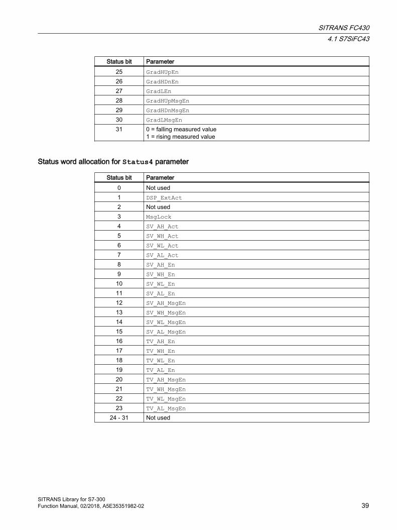
Status word allocation for Status4 parameter
Status bit Parameter0 Not used1 DSP_ExtAct2 Not used3 MsgLock4 SV_AH_Act5 SV_WH_Act6 SV_WL_Act7 SV_AL_Act8 SV_AH_En9 SV_WH_En10 SV_WL_En11 SV_AL_En12 SV_AH_MsgEn13 SV_WH_MsgEn14 SV_WL_MsgEn15 SV_AL_MsgEn16 TV_AH_En17 TV_WH_En18 TV_WL_En19 TV_AL_En20 TV_AH_MsgEn21 TV_WH_MsgEn22 TV_WL_MsgEn23 TV_AL_MsgEn
24 - 31 Not used
SITRANS FC4304.1 S7SiFC43
SITRANS Library for S7-300Function Manual, 02/2018, A5E35351982-02 39

Status word allocation for Status5 parameter
Status bit Parameter0 TV_AH_Act1 TV_WH_Act2 TV_WL_Act3 TV_AL_Act4 QV_AH_Act5 QV_WH_Act6 QV_WL_Act7 QV_AL_Act8 QV_AH_En9 QV_WH_En10 QV_WL_En11 QV_AL_En12 QV_AH_MsgEn13 QV_WH_MsgEn14 QV_WL_MsgEn15 QV_AL_MsgEn16 "Interlock" button is enabled
17 - 18 Not used19 1 = Intlock is active
20 - 21 Not used22 Display for interlocks in block icon23 1 = Any Interlock is active24 ForceDSrt25 ForceDStp26 ForceDPause27 ForceDCont28 Not used29 Interlocks not released30 1 = Error when reading acyclic data (active only for the duration of one cycle)31 1 = Error when writing acyclic data (active only for the duration of one cycle)
Status word allocation for Status6 parameter
Status bit Parameter0 QWronDev1 External control system fault (CSF)2 Mode switchover error3 SV is configured as dosing unit4 SV is configured as totalizer5 TV is configured as totalizer6 QV is configured as totalizer
SITRANS FC4304.1 S7SiFC43
SITRANS Library for S7-30040 Function Manual, 02/2018, A5E35351982-02

Status bit Parameter7 - 10 Not used
11 SV input is used12 TV input is used13 QV input is used14 1 = At least one PV message is released15 1 = At least one SV message is released16 1 = At least one TV message is released17 1 = At least one QV message is released18 "Custody transfer mode" is active19 Not used20 LocalSVAct
21 - 22 Not used23 Mode switchover error
4.1.2 Operating modes of S7SiFC43Every HART auxiliary variable configured with PDM in the device has its own operating mode switchover. The operating modes of the S7SiFC43 block selectable in each case depend on whether a totalizer or dosing value is configured for the respective HART auxiliary variable or only a simple measured value.
Operating modes of S7SiFC43 for simple measured valueThe block can be operated using the following modes:
● On
● Out of service
"On"
You can find general information about the "On" mode in the "On" section.
"Out of service"
You can find general information about the "Out of service" mode in the Out of service section.
The descriptions of the operating modes are identical for SitrFC43 and the APL; refer to the online help for the standard APL blocks for information on them.
Operating modes of S7SiFC43 for totalizer or dosing valueThe block can be operated using the following modes:
● Local mode
● Automatic mode
● Manual mode
● Out of service
SITRANS FC4304.1 S7SiFC43
SITRANS Library for S7-300Function Manual, 02/2018, A5E35351982-02 41
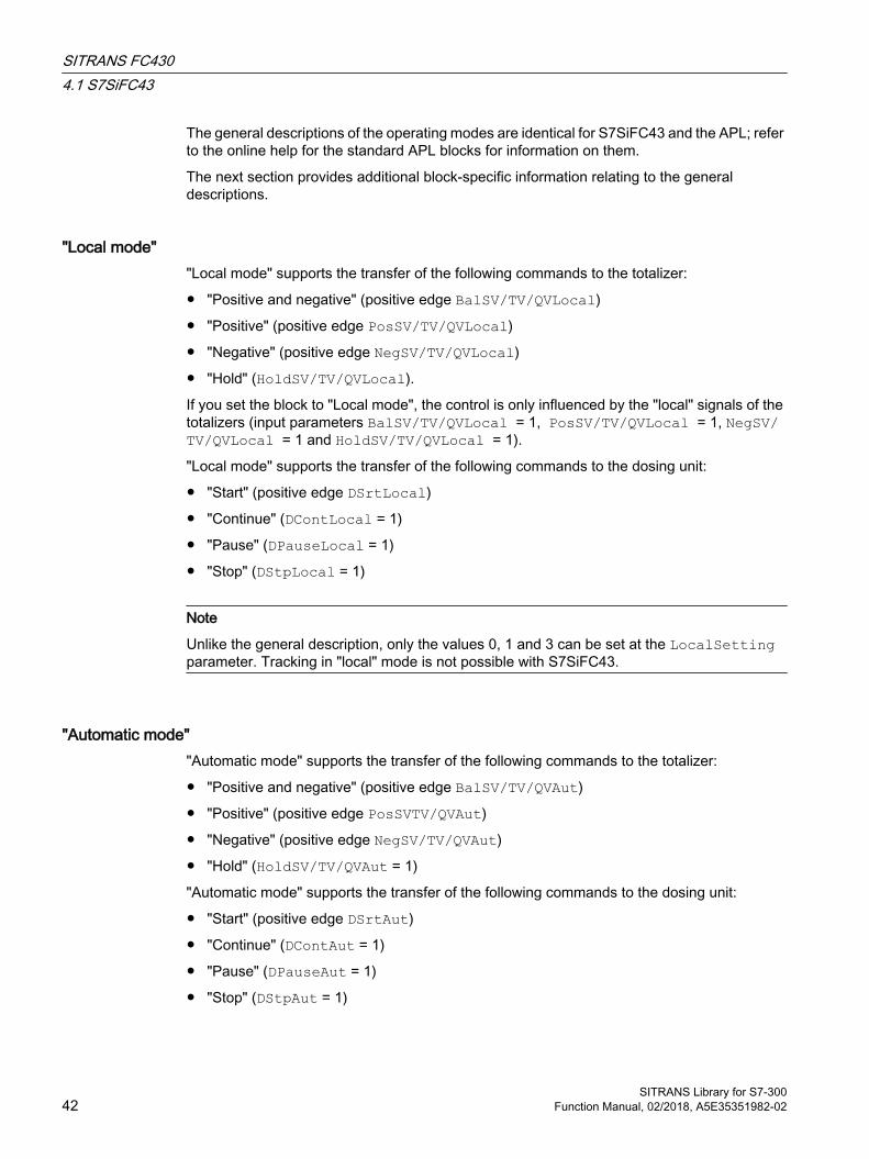
The general descriptions of the operating modes are identical for S7SiFC43 and the APL; refer to the online help for the standard APL blocks for information on them.
The next section provides additional block-specific information relating to the general descriptions.
"Local mode""Local mode" supports the transfer of the following commands to the totalizer:
● "Positive and negative" (positive edge BalSV/TV/QVLocal)
● "Positive" (positive edge PosSV/TV/QVLocal)
● "Negative" (positive edge NegSV/TV/QVLocal)
● "Hold" (HoldSV/TV/QVLocal).
If you set the block to "Local mode", the control is only influenced by the "local" signals of the totalizers (input parameters BalSV/TV/QVLocal = 1, PosSV/TV/QVLocal = 1, NegSV/TV/QVLocal = 1 and HoldSV/TV/QVLocal = 1).
"Local mode" supports the transfer of the following commands to the dosing unit:
● "Start" (positive edge DSrtLocal)
● "Continue" (DContLocal = 1)
● "Pause" (DPauseLocal = 1)
● "Stop" (DStpLocal = 1)
Note
Unlike the general description, only the values 0, 1 and 3 can be set at the LocalSetting parameter. Tracking in "local" mode is not possible with S7SiFC43.
"Automatic mode""Automatic mode" supports the transfer of the following commands to the totalizer:
● "Positive and negative" (positive edge BalSV/TV/QVAut)
● "Positive" (positive edge PosSVTV/QVAut)
● "Negative" (positive edge NegSV/TV/QVAut)
● "Hold" (HoldSV/TV/QVAut = 1)
"Automatic mode" supports the transfer of the following commands to the dosing unit:
● "Start" (positive edge DSrtAut)
● "Continue" (DContAut = 1)
● "Pause" (DPauseAut = 1)
● "Stop" (DStpAut = 1)
SITRANS FC4304.1 S7SiFC43
SITRANS Library for S7-30042 Function Manual, 02/2018, A5E35351982-02

"Manual mode""Manual mode" supports the transfer of the following commands to the totalizer:
● "Positive and negative" (positive edge BalSV/TV/QVMan)
● "Positive" (positive edge PosSV/TV/QVMan)
● "Negative" (positive edge NegSV/TV/QVMan)
● "Hold" (HoldSV/TV/QVMan = 1)
"Manual mode" enables the transfer of the following commands to the dosing unit:
● "Start" (positive edge DSrtMan)
● "Continue" (DContMan = 1)
● "Pause" (DPauseMan = 1)
● "Stop" (DStpMan = 1)
"Out of service"For general information about the "out of service" mode, refer to the APL Online Help.
4.1.3 Functions of S7SiFC43The functions for this block are listed below.
Configuration DataThe configuration data comprises the units, the configuration of the PV_In input and the HART auxiliary variables SV, QV and PV and the limits for messages. After a change is made in the device, reading of configuration data must be triggered with "Read configuration data" in the parameter view of the faceplate. If the parameters were read back before a complete download to the PLC, the configuration does not need to be reloaded from the device.
The message limits of the S7SiFC43 are only transferred to the device when the alarm configuration is synchronized with the device (Feature Bit 7 = TRUE).
The S7SiFC43 function block has the following configuration data which can be read out of the FC430 by means of the "Read configuration data" command:
Description Block parameters (I/O)Configuration of PV, SV, TV, QV in‐puts
PV_Meas0, PV_Meas1, PV_Meas2, PV_Meas3, PV_Meas4
Configuration of totalizer Tot1/2/3ChConfiguration of dosing value InDinputSel/DinputSelUnits PV, SV, TV, QV PV/SV/TV/QV_Unit
Mfl_Unit, Vfl_UnitDSP_Unit
Scaling PV ScaleInNames for fractions A and B FractnATxt, FractnBTxt
SITRANS FC4304.1 S7SiFC43
SITRANS Library for S7-300Function Manual, 02/2018, A5E35351982-02 43

Limits PV, SV, TV, QV InPV/SV/TV/QV_AH_Lim, PV/SV/TV/QV_AH_Lim InPV/SV/TV/QV_WH_Lim, PV/SV/TV/QV_WH_Lim InPV/SV/TV/QV_WL_Lim, PV/SV/TV/QV_WL_Lim InPV/SV/TV/QV_AL_Lim, PV/SV/TV/QV_AL_Lim InPV/SV/TV/QV_Hyst, PV/SV/TV/QV_Hyst
Limit values of the limits LimPV/SV/TV/QVOpScalePreset value of totalizer InSV/TV/QVPreVal, SV/TV/QVPreValTotalizer command BalSV/TV/QVMan
PosSV/TV/QVManNegSV/TV/QVManHoldSV/TV/QVMan
Low flow cut-off suppression (mass/vol‐ume)
InMflZFSupp/MflZFSuppInVflZFSupp/VflZFSupp
Type of dosing DModeActive dosing recipe DActRecOpDosing recipe name InRcp1/2/3/4/5NameDosing compensation DCompOp/DCompDosing cycle counter DCyclCntDosing state DState
Limit monitoringThe block monitors the process values PV_In, SV, TV und QV if they are configured for limits. All values are written cyclically from the module into the process image of the controller. Configuration of the limits is carried out either by means of PDM and imported by reading the configuration data from the block, or can be carried out on the block independent of the module (see Feature bit 7).
You can monitor the process values PV_In, SV, TV and QV for the following high and low alarm and warning limits:
● (In)PV/SV/TV/QV_AH_Lim: Limit for high alarm
● (In)PV/SV/TV/QV_AL_Lim: Limit for low alarm
● (In)PV/SV/TV/QV_Hyst: Hysteresis
● (In)PV/SV/TV/QV_WH_Lim: Limit for high warning
● (In)PV/SV/TV/QV_WL_Lim: Limit for low warning
The result of limit monitoring is returned at the interconnectable output parameters:
● PV/SV/TV/QV_AH_Act = 1: Limit for high alarm reached or exceeded
● PV/SV/TV/QV_AL_Act = 1: Limit for low alarm reached or undershot
● PV/SV/TV/QV_WH_Act = 1: Limit for high warning reached or exceeded
● PV/SV/TV/QV_WL_Act = 1: Limit for low warning reached or undershot
Monitoring is always enabled using the input parameters:
● PV/SV/TV/QV_AH_En = 1: Monitoring of the high alarm limits
● PV/SV/TV/QV_AL_En = 1: Monitoring of the low alarm limits
SITRANS FC4304.1 S7SiFC43
SITRANS Library for S7-30044 Function Manual, 02/2018, A5E35351982-02

● PV/SV/TV/QV_WH_En = 1: Monitoring of the high warning limits
● PV/SV/TV/QV_WL_En = 1: Monitoring of the low warning limits
The corresponding message is suppressed using the parameters:
● PV/SV/TV/QV_AH_MsgEn = 0: Alarm (high) messages are suppressed
● PV/SV/TV/QV_AL_MsgEn = 0: Alarm (low) messages are suppressed
● PV/SV/TV/QV_WH_MsgEn = 0: Warning (high) messages are suppressed
● PV/SV/TV/QV_WL_MsgEn = 0: Warning (low) messages are suppressed
You can define a hysteresis (PV/SV/TV/QV_Hyst) for the limits, for example to suppress signal flatter. You can also modify the limits and hysteresis via the faceplate.
Gradient monitoring The gradient PV_Grad is calculated by means of a delay function configurable using LagTime. During calculation of the gradient, jumps in the input value PV_In are smoothed.
The peak values of the gradient are output in the output parameters PV_GradNP (negative gradient) and PV_GradPP (positive gradient). These are reset when the operator enters the corresponding command for resetting.
The slope of the gradient PV_Grad can be monitored for the following limits:
● Limit (high) for the positive gradient (GradHUpLim)
● Limit (high) for the negative gradient (GradHDnLim)
● Limit (low) for the absolute gradient (GradLLim)
Activation of the individual monitoring functions is carried out at the corresponding "Enable" parameters, e.g. GradHUpEn for activating the high gradient limit for positive gradients (GradHUpLim).
Reaching or violation of your defined limits is indicated at the corresponding "Active" output parameters, e.g. by means of GradHUpAct = 1 for the limit (high) for the positive gradient.
Messages can be output for these alarms. You can activate these as follows:
● Message for alarms (high) for the positive gradient: GradHUpMsgEn = 1
● Message for alarms (high) for the negative gradient: GradHDnMsgEn = 1
● Message for alarms (low) for the absolute gradient: GradLMsgEn = 1
Suppressing messages using the MsgLock parameterThis block provides the standard "Suppressing messages using the MsgLock parameter" function that is described in the APL Online Help.
Selecting a unit of measureThe units for the process values PV_In, SV, TV and QV are configured on the FC430 device via PDM and read out by operator action in the "Parameters" faceplate view with "Read configuration".
SITRANS FC4304.1 S7SiFC43
SITRANS Library for S7-300Function Manual, 02/2018, A5E35351982-02 45

Configurable reactions using the Feature I/OThe following responses are available for this block at the respective bits of the Feature I/O. If a description is not available here, it can be referenced in the APL Online Help.
Bit Feature0 Define the startup characteristics1 Reaction to the Out of service mode2 Reset the commands for switching the operating mode3 Enable resetting of commands for the control settings4 Set switch or button mode6 Release the zero balancing in the parameter view in the faceplate7 1 = Message limits are read from the device and transferred to the device in case of a change10 Exit local mode11 Stop dosing in the event of a flow alarm12 Read dosing state automatically
During the start of the controller and when the connection between device and controller is reestablished after an interruption, the dosing state is read automatically by means of acyclic communication.Note:: Only 8 acyclic read jobs can be executed simultaneously for each Profibus line. If additional devices want to read acyclic data simultaneously, the read job is canceled with an error. Alternatively, the dosing state can be read with the click of a button in the faceplate.
14 Enable dosing mode17 Activate smooth change from manual to automatic mode22 Update acknowledgment and error status of the message call23 1 = Separate evaluation for excluded and simulated interlock signals24 Enable local operator authorization25 Suppress all messages if MsgLock = 126 Reaction of the switching points in "Out of service" mode28 Disable switching points29 Signaling limit violation
Operator authorizationsThis block provides the standard operator permissions that are described in the APL Online Help.
The block has the following permissions for the OS_Perm parameter:
Bit Function0 1 = Operator can switch PV to "On" mode1 1 = Operator can switch PV to "Out of service" mode2 1 = Operator can switch SV to "Automatic" mode3 1 = Operator can switch SV to "Manual" mode4 1 = Operator can switch SV to "Local" mode5 1 = Operator can switch SV to "On" mode6 1 = Operator can switch SV to "Out of service" mode
SITRANS FC4304.1 S7SiFC43
SITRANS Library for S7-30046 Function Manual, 02/2018, A5E35351982-02
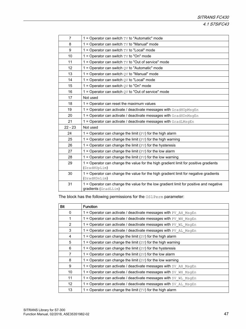
7 1 = Operator can switch TV to "Automatic" mode8 1 = Operator can switch TV to "Manual" mode9 1 = Operator can switch TV to "Local" mode10 1 = Operator can switch TV to "On" mode11 1 = Operator can switch TV to "Out of service" mode12 1 = Operator can switch QV to "Automatic" mode13 1 = Operator can switch QV to "Manual" mode14 1 = Operator can switch QV to "Local" mode15 1 = Operator can switch QV to "On" mode16 1 = Operator can switch QV to "Out of service" mode17 Not used18 1 = Operator can reset the maximum values19 1 = Operator can activate / deactivate messages with GradHUpMsgEn20 1 = Operator can activate / deactivate messages with GradHDnMsgEn 21 1 = Operator can activate / deactivate messages with GradLMsgEn
22 - 23 Not used24 1 = Operator can change the limit (PV) for the high alarm25 1 = Operator can change the limit (PV) for the high warning26 1 = Operator can change the limit (PV) for the hysteresis27 1 = Operator can change the limit (PV) for the low alarm28 1 = Operator can change the limit (PV) for the low warning29 1 = Operator can change the value for the high gradient limit for positive gradients
(GradHUpLim)30 1 = Operator can change the value for the high gradient limit for negative gradients
(GradHDnLim)31 1 = Operator can change the value for the low gradient limit for positive and negative
gradients (GradLLim)
The block has the following permissions for the OS1Perm parameter:
Bit Function0 1 = Operator can activate / deactivate messages with PV_AH_MsgEn1 1 = Operator can activate / deactivate messages with PV_WH_MsgEn2 1 = Operator can activate / deactivate messages with PV_WL_MsgEn3 1 = Operator can activate / deactivate messages with PV_AL_MsgEn4 1 = Operator can change the limit (SV) for the high alarm5 1 = Operator can change the limit (SV) for the high warning6 1 = Operator can change the limit (SV) for the hysteresis7 1 = Operator can change the limit (SV) for the low alarm8 1 = Operator can change the limit (SV) for the low warning9 1 = Operator can activate / deactivate messages with SV_AH_MsgEn
10 1 = Operator can activate / deactivate messages with SV_WH_MsgEn11 1 = Operator can activate / deactivate messages with SV_WL_MsgEn12 1 = Operator can activate / deactivate messages with SV_AL_MsgEn13 1 = Operator can change the limit (TV) for the high alarm
SITRANS FC4304.1 S7SiFC43
SITRANS Library for S7-300Function Manual, 02/2018, A5E35351982-02 47
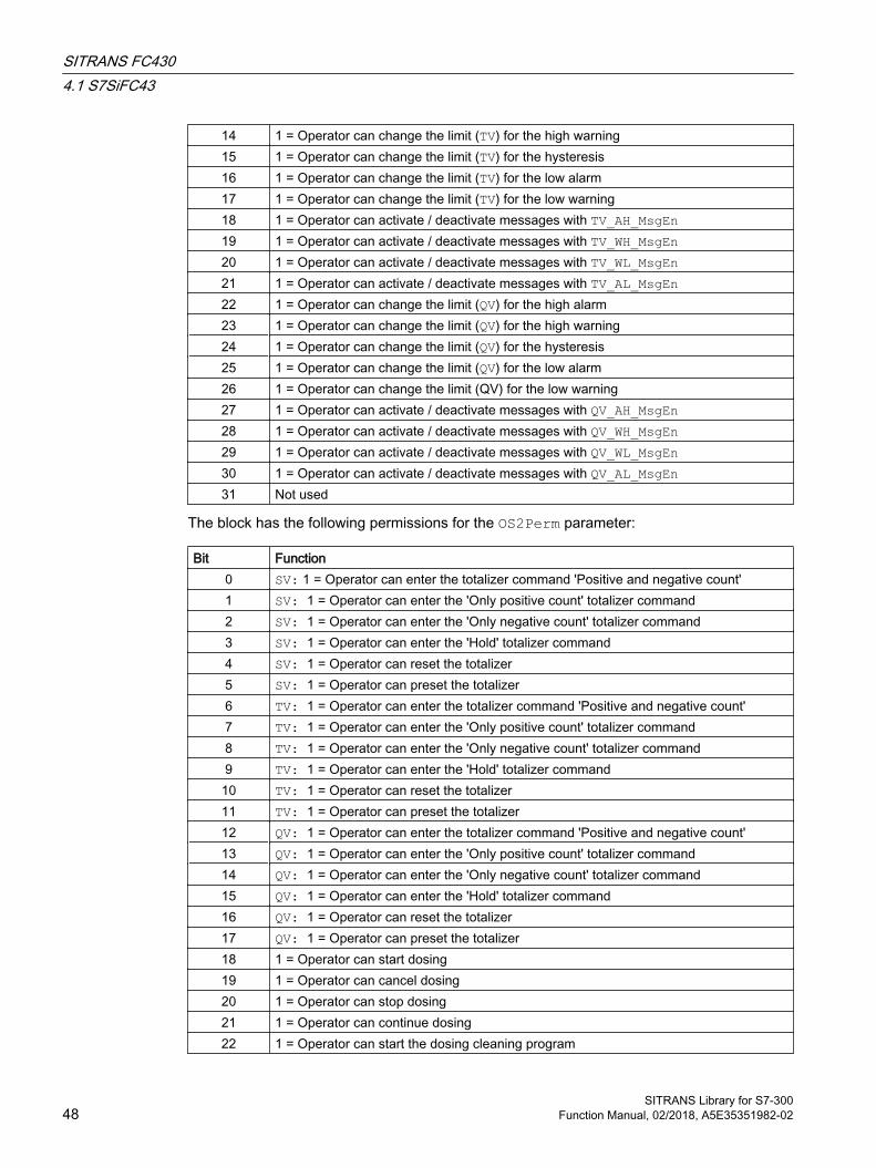
14 1 = Operator can change the limit (TV) for the high warning15 1 = Operator can change the limit (TV) for the hysteresis16 1 = Operator can change the limit (TV) for the low alarm17 1 = Operator can change the limit (TV) for the low warning18 1 = Operator can activate / deactivate messages with TV_AH_MsgEn19 1 = Operator can activate / deactivate messages with TV_WH_MsgEn20 1 = Operator can activate / deactivate messages with TV_WL_MsgEn21 1 = Operator can activate / deactivate messages with TV_AL_MsgEn22 1 = Operator can change the limit (QV) for the high alarm23 1 = Operator can change the limit (QV) for the high warning24 1 = Operator can change the limit (QV) for the hysteresis25 1 = Operator can change the limit (QV) for the low alarm26 1 = Operator can change the limit (QV) for the low warning27 1 = Operator can activate / deactivate messages with QV_AH_MsgEn28 1 = Operator can activate / deactivate messages with QV_WH_MsgEn29 1 = Operator can activate / deactivate messages with QV_WL_MsgEn30 1 = Operator can activate / deactivate messages with QV_AL_MsgEn31 Not used
The block has the following permissions for the OS2Perm parameter:
Bit Function0 SV: 1 = Operator can enter the totalizer command 'Positive and negative count'1 SV: 1 = Operator can enter the 'Only positive count' totalizer command2 SV: 1 = Operator can enter the 'Only negative count' totalizer command3 SV: 1 = Operator can enter the 'Hold' totalizer command4 SV: 1 = Operator can reset the totalizer5 SV: 1 = Operator can preset the totalizer6 TV: 1 = Operator can enter the totalizer command 'Positive and negative count'7 TV: 1 = Operator can enter the 'Only positive count' totalizer command8 TV: 1 = Operator can enter the 'Only negative count' totalizer command9 TV: 1 = Operator can enter the 'Hold' totalizer command10 TV: 1 = Operator can reset the totalizer11 TV: 1 = Operator can preset the totalizer12 QV: 1 = Operator can enter the totalizer command 'Positive and negative count'13 QV: 1 = Operator can enter the 'Only positive count' totalizer command14 QV: 1 = Operator can enter the 'Only negative count' totalizer command15 QV: 1 = Operator can enter the 'Hold' totalizer command16 QV: 1 = Operator can reset the totalizer17 QV: 1 = Operator can preset the totalizer18 1 = Operator can start dosing19 1 = Operator can cancel dosing20 1 = Operator can stop dosing21 1 = Operator can continue dosing22 1 = Operator can start the dosing cleaning program
SITRANS FC4304.1 S7SiFC43
SITRANS Library for S7-30048 Function Manual, 02/2018, A5E35351982-02

23 1 = Operator can reset the dosing cycle counter24 1 = Operator can select external setpoint25 1 = Operator can select internal setpoint26 1 = Operator can select dosing recipe27 1 = Operator can change dosing quantity28 SV: 1 = Operator can change preset value of totalizer29 TV: 1 = Operator can change preset value of totalizer30 QV: 1 = Operator can change preset value of totalizer31 1 = Operator can start automatic zero balancing
The block has the following permissions for the OS3Perm parameter:
Bit Function0 1 = Operator can read configuration data and dosing state from device1 1 = Operator can write configuration data to device2 1 = Operator can enter password3 Not used
Display and operating range for process values and limitsThe inputs PV_OpScaleH/L are used as display and operating range for the process value PV_In.
Generating instance-specific messagesThis block provides one "Instance-specific message".
SIMATIC BATCH functionalityThis block provides the standard "SIMATIC BATCH functionality" function that is described in the APL Online Help.
4.1.4 Error handling of S7SiFC43For general information on error handling at all blocks, refer to the "Error handling" section in the APL Online Help.
The following errors can be displayed for this block:
● Error numbers
● Control system fault (CSF)
Control system fault (CSF) An external signal can be activated via the CSF input. A control system fault is triggered if this signal = 1. Refer to the "Error handling" section in the APL Online Help.
SITRANS FC4304.1 S7SiFC43
SITRANS Library for S7-300Function Manual, 02/2018, A5E35351982-02 49
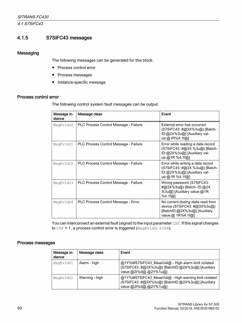
4.1.5 S7SiFC43 messages
Messaging The following messages can be generated for this block:
● Process control error
● Process messages
● Instance-specific message
Process control error The following control system fault messages can be output:
Message in‐stance
Message class Event
MsgEvId20 PLC Process Control Message - Failure External error has occurred (S7SiFC43: #@3X%3u@) [Batch‐ID:@2X%3u@] [Auxiliary val‐ue:@1R%4.1f@]
MsgEvId21 PLC Process Control Message - Failure Error while reading a data record (S7SiFC43: #@3X %3u@) [Batch‐ID:@2X%3u@] [Auxiliary val‐ue:@1R %4.1f@]
MsgEvId22 PLC Process Control Message - Failure Error while writing a data record (S7SiFC43: #@3X %3u@) [Batch‐ID:@2X%3u@] [Auxiliary val‐ue:@1R %4.1f@]
MsgEvId23 PLC Process Control Message - Failure Wrong password (S7SiFC43: #@3X%3u@) [Batch‐ ID:@2X%3u@] [Auxiliary value:@1R%4.1f@]
MsgEvId24 PLC Process Control Message - Error No current dosing state read from device (S7SiFC43: #@3X%3u@) [BatchID:@2X%3u@] [Auxiliary value:@ 1R%4.1f@]
You can interconnect an external fault (signal) to the input parameter CSF. If this signal changes to CSF = 1, a process control error is triggered (MsgEvld3, SIG4).
Process messages
Message in‐stance
Message class Event
MsgEvId01 Alarm - high @1Y%t#S7SiFC43_MeasVal@ - High alarm limit violated (S7SiFC43: #@3X%3u@) [BatchID:@2X%3u@] [Auxiliary value:@2I%d@.@2Y%1u@]
MsgEvId02 Warning - high @1Y%t#S7SiFC43_MeasVal@ - High warning limit violated (S7SiFC43: #@3X%3u@) [BatchID:@2X%3u@] [Auxiliary value:@2I%d@.@2Y%1u@]
SITRANS FC4304.1 S7SiFC43
SITRANS Library for S7-30050 Function Manual, 02/2018, A5E35351982-02
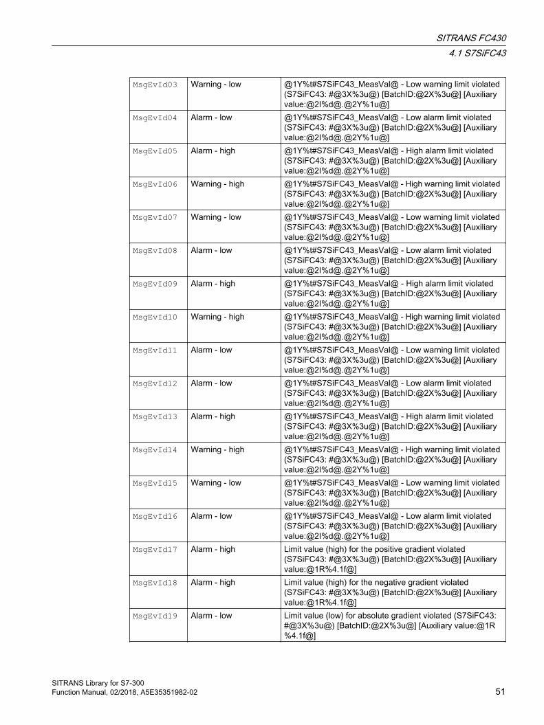
MsgEvId03 Warning - low @1Y%t#S7SiFC43_MeasVal@ - Low warning limit violated (S7SiFC43: #@3X%3u@) [BatchID:@2X%3u@] [Auxiliary value:@2I%d@.@2Y%1u@]
MsgEvId04 Alarm - low @1Y%t#S7SiFC43_MeasVal@ - Low alarm limit violated (S7SiFC43: #@3X%3u@) [BatchID:@2X%3u@] [Auxiliary value:@2I%d@.@2Y%1u@]
MsgEvId05 Alarm - high @1Y%t#S7SiFC43_MeasVal@ - High alarm limit violated (S7SiFC43: #@3X%3u@) [BatchID:@2X%3u@] [Auxiliary value:@2I%d@.@2Y%1u@]
MsgEvId06 Warning - high @1Y%t#S7SiFC43_MeasVal@ - High warning limit violated (S7SiFC43: #@3X%3u@) [BatchID:@2X%3u@] [Auxiliary value:@2I%d@.@2Y%1u@]
MsgEvId07 Warning - low @1Y%t#S7SiFC43_MeasVal@ - Low warning limit violated (S7SiFC43: #@3X%3u@) [BatchID:@2X%3u@] [Auxiliary value:@2I%d@.@2Y%1u@]
MsgEvId08 Alarm - low @1Y%t#S7SiFC43_MeasVal@ - Low alarm limit violated (S7SiFC43: #@3X%3u@) [BatchID:@2X%3u@] [Auxiliary value:@2I%d@.@2Y%1u@]
MsgEvId09 Alarm - high @1Y%t#S7SiFC43_MeasVal@ - High alarm limit violated (S7SiFC43: #@3X%3u@) [BatchID:@2X%3u@] [Auxiliary value:@2I%d@.@2Y%1u@]
MsgEvId10 Warning - high @1Y%t#S7SiFC43_MeasVal@ - High warning limit violated (S7SiFC43: #@3X%3u@) [BatchID:@2X%3u@] [Auxiliary value:@2I%d@.@2Y%1u@]
MsgEvId11 Alarm - low @1Y%t#S7SiFC43_MeasVal@ - Low warning limit violated (S7SiFC43: #@3X%3u@) [BatchID:@2X%3u@] [Auxiliary value:@2I%d@.@2Y%1u@]
MsgEvId12 Alarm - low @1Y%t#S7SiFC43_MeasVal@ - Low alarm limit violated (S7SiFC43: #@3X%3u@) [BatchID:@2X%3u@] [Auxiliary value:@2I%d@.@2Y%1u@]
MsgEvId13 Alarm - high @1Y%t#S7SiFC43_MeasVal@ - High alarm limit violated (S7SiFC43: #@3X%3u@) [BatchID:@2X%3u@] [Auxiliary value:@2I%d@.@2Y%1u@]
MsgEvId14 Warning - high @1Y%t#S7SiFC43_MeasVal@ - High warning limit violated (S7SiFC43: #@3X%3u@) [BatchID:@2X%3u@] [Auxiliary value:@2I%d@.@2Y%1u@]
MsgEvId15 Warning - low @1Y%t#S7SiFC43_MeasVal@ - Low warning limit violated (S7SiFC43: #@3X%3u@) [BatchID:@2X%3u@] [Auxiliary value:@2I%d@.@2Y%1u@]
MsgEvId16 Alarm - low @1Y%t#S7SiFC43_MeasVal@ - Low alarm limit violated (S7SiFC43: #@3X%3u@) [BatchID:@2X%3u@] [Auxiliary value:@2I%d@.@2Y%1u@]
MsgEvId17 Alarm - high Limit value (high) for the positive gradient violated (S7SiFC43: #@3X%3u@) [BatchID:@2X%3u@] [Auxiliary value:@1R%4.1f@]
MsgEvId18 Alarm - high Limit value (high) for the negative gradient violated (S7SiFC43: #@3X%3u@) [BatchID:@2X%3u@] [Auxiliary value:@1R%4.1f@]
MsgEvId19 Alarm - low Limit value (low) for absolute gradient violated (S7SiFC43: #@3X%3u@) [BatchID:@2X%3u@] [Auxiliary value:@1R %4.1f@]
SITRANS FC4304.1 S7SiFC43
SITRANS Library for S7-300Function Manual, 02/2018, A5E35351982-02 51
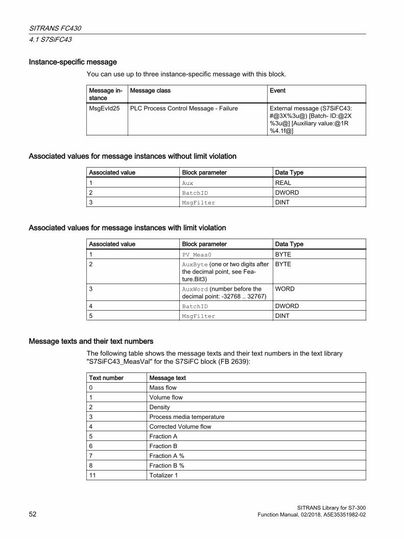
Instance-specific message You can use up to three instance-specific message with this block.
Message in‐stance
Message class Event
MsgEvId25 PLC Process Control Message - Failure External message (S7SiFC43: #@3X%3u@) [Batch‐ ID:@2X%3u@] [Auxiliary value:@1R%4.1f@]
Associated values for message instances without limit violation
Associated value Block parameter Data Type1 Aux REAL2 BatchID DWORD3 MsgFilter DINT
Associated values for message instances with limit violation
Associated value Block parameter Data Type1 PV_Meas0 BYTE2 AuxByte (one or two digits after
the decimal point, see Fea‐ture.Bit3)
BYTE
3 AuxWord (number before the decimal point: -32768 .. 32767)
WORD
4 BatchID DWORD5 MsgFilter DINT
Message texts and their text numbersThe following table shows the message texts and their text numbers in the text library "S7SiFC43_MeasVal" for the S7SiFC block (FB 2639):
Text number Message text0 Mass flow1 Volume flow2 Density3 Process media temperature4 Corrected Volume flow5 Fraction A6 Fraction B7 Fraction A %8 Fraction B %11 Totalizer 1
SITRANS FC4304.1 S7SiFC43
SITRANS Library for S7-30052 Function Manual, 02/2018, A5E35351982-02
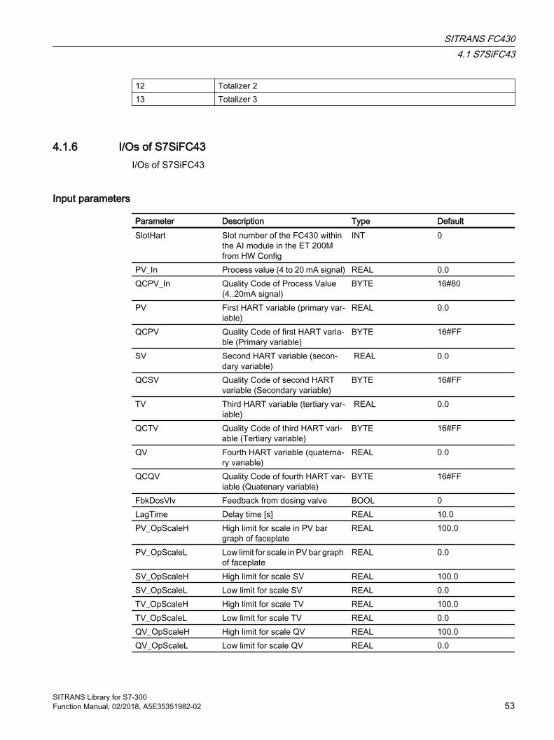
12 Totalizer 213 Totalizer 3
4.1.6 I/Os of S7SiFC43I/Os of S7SiFC43
Input parameters
Parameter Description Type DefaultSlotHart Slot number of the FC430 within
the AI module in the ET 200M from HW Config
INT 0
PV_In Process value (4 to 20 mA signal) REAL 0.0QCPV_In Quality Code of Process Value
(4..20mA signal)BYTE 16#80
PV First HART variable (primary var‐iable)
REAL 0.0
QCPV Quality Code of first HART varia‐ble (Primary variable)
BYTE 16#FF
SV Second HART variable (secon‐dary variable)
REAL 0.0
QCSV Quality Code of second HART variable (Secondary variable)
BYTE 16#FF
TV Third HART variable (tertiary var‐iable)
REAL 0.0
QCTV Quality Code of third HART vari‐able (Tertiary variable)
BYTE 16#FF
QV Fourth HART variable (quaterna‐ry variable)
REAL 0.0
QCQV Quality Code of fourth HART var‐iable (Quatenary variable)
BYTE 16#FF
FbkDosVlv Feedback from dosing valve BOOL 0LagTime Delay time [s] REAL 10.0PV_OpScaleH High limit for scale in PV bar
graph of faceplateREAL 100.0
PV_OpScaleL Low limit for scale in PV bar graph of faceplate
REAL 0.0
SV_OpScaleH High limit for scale SV REAL 100.0SV_OpScaleL Low limit for scale SV REAL 0.0TV_OpScaleH High limit for scale TV REAL 100.0TV_OpScaleL Low limit for scale TV REAL 0.0QV_OpScaleH High limit for scale QV REAL 100.0QV_OpScaleL Low limit for scale QV REAL 0.0
SITRANS FC4304.1 S7SiFC43
SITRANS Library for S7-300Function Manual, 02/2018, A5E35351982-02 53
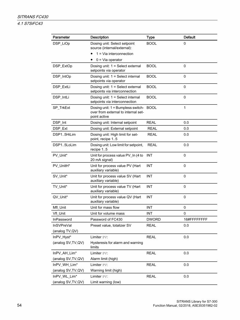
Parameter Description Type DefaultDSP_LiOp Dosing unit: Select setpoint
source (internal/external):● 1 = Via interconnection● 0 = Via operator
BOOL 0
DSP_ExtOp Dosing unit: 1 = Select external setpoints via operator
BOOL 0
DSP_IntOp Dosing unit: 1 = Select internal setpoints via operator
BOOL 0
DSP_ExtLi Dosing unit: 1 = Select external setpoints via interconnection
BOOL 0
DSP_IntLi Dosing unit: 1 = Select internal setpoints via interconnection
BOOL 0
SP_TrkExt Dosing unit: 1 = Bumpless switch‐over from external to internal set‐point active
BOOL 1
DSP_Int Dosing unit: Internal setpoint REAL 0.0DSP_Ext Dosing unit: External setpoint REAL 0.0DSP1..5HiLim Dosing unit: High limit for set‐
point, recipe 1..5 REAL 0.0
DSP1..5LoLim Dosing unit: Low limit for setpoint, recipe 1..5
REAL 0.0
PV_Unit* Unit for process value PV_In (4 to 20 mA signal)
INT 0
PV_UnitH* Unit for process value PV (Hart auxiliary variable)
INT 0
SV_Unit* Unit for process value SV (Hart auxiliary variable)
INT 0
TV_Unit* Unit for process value TV (Hart auxiliary variable)
INT 0
QV_Unit* Unit for process value QV (Hart auxiliary variable)
INT 0
Mfl_Unit Unit for mass flow INT 0Vfl_Unit Unit for volume mass INT 0InPassword Password of FC430 DWORD 16#FFFFFFFFInSVPreVal(analog TV,QV)
Preset value, totalizer SV REAL 0.0
InPV_Hyst*(analog SV,TV,QV)
Limiter PV:Hysteresis for alarm and warning limits
REAL 0.0
InPV_AH_Lim*(analog SV,TV,QV)
Limiter PV:Alarm limit (high)
REAL 0.0
InPV_WH_Lim*(analog SV,TV,QV)
Limiter PV:Warning limit (high)
REAL 0.0
InPV_WL_Lim*(analog SV,TV,QV)
Limiter PV:Limit warning (low)
REAL 0.0
SITRANS FC4304.1 S7SiFC43
SITRANS Library for S7-30054 Function Manual, 02/2018, A5E35351982-02

Parameter Description Type DefaultInPV_AL_Lim*(analog SV,TV,QV)
Limiter PV:Alarm limit (low)
REAL 0.0
PV_AH_En(analog SV,TV,QV)
1 = Activate process value PV (high) alarm
BOOL 1
PV_WH_En(analog SV,TV,QV)
1 = Activate process value PV (high) warning
BOOL 1
PV_WL_En(analog SV,TV,QV)
1 = Activate process value PV (low) warning
BOOL 1
PV_AL_En(analog SV,TV,QV)
1 = Activate process value PV (low) alarm
BOOL 1
PV_AH_MsgEn(analog SV,TV,QV)
1 = Activate message for process value PV (high) alarm
BOOL 1
PV_WH_MsgEn(analog SV,TV,QV)
1 = Activate message for process value PV (high) warning
BOOL 1
PV_WL_MsgEn(analog SV,TV,QV)
1 = Activate message for process value PV (low) warning
BOOL 1
PV_AL_MsgEn(analog SV,TV,QV)
1 = Activate message for process value PV (low) alarm
BOOL 1
GradHUpLim Gradient monitoring: Limit (high) for the positive gradient
REAL 10.0
GradHDnLim Gradient monitoring: Limit (high) for the negative gradient
REAL 10.0
GradLLim Gradient monitoring: Limit (low) for the absolute gradient
REAL 1.0
BalSVAut(analog TV,QV)
Totalizer SV: Up counter for pos‐itive flow and down counter for negative flow in automatic mode
BOOL 0
PosSVAut(analog TV,QV)
Totalizer SV: Increment only for positive flow in automatic mode
BOOL 0
NegSVAut(analog TV,QV)
Totalizer SV: Decrement only for negative flow in automatic mode
BOOL 0
HoldSVAut(analog TV,QV)
Totalizer SV: Stop totalizer in au‐tomatic mode
BOOL 0
ReTotSVLi(analog TV,QV)
1 = Reset totalizer SV via inter‐connection
BOOL 0
PreSVLi(analog TV,QV)
1 = Set totalizer SV via intercon‐nection to the preset value InSVPreVal
BOOL 0
BalSVMan*(analog TV,QV)
Totalizer SV: Up counter for pos‐itive flow and down counter for negative flow in manual mode
BOOL 0
PosSVMan*(analog TV,QV)
Totalizer SV: Increment only for positive flow in manual mode
BOOL 0
SITRANS FC4304.1 S7SiFC43
SITRANS Library for S7-300Function Manual, 02/2018, A5E35351982-02 55

Parameter Description Type DefaultNegSVMan*(analog TV,QV)
Totalizer SV: Decrement only for negative flow in manual mode
BOOL 0
HoldSVMan*(analog TV,QV)
Totalizer SV: Stop totalizer in manual mode
BOOL 0
ReTotSVOp*(analog TV,QV)
1 = Reset totalizer SV via opera‐tor input
BOOL 0
PreSVOp*(analog TV,QV)
1 = Set totalizer SV via intercon‐nection to the preset value InSVPreVal
BOOL 0
CTModeAct Custody transfer mode active BOOL 0DosingEn 1 = Connected FC430 has the
dosing functionalityBOOL 0
DMode Dosing mode: 0 : Deactivated 1 : One-step dosing 2 : Two-step dosing 3 : Analog dosing
BYTE 0
DSrtAut Dosing unit: 1 = Select Start in "automatic mode"
BOOL 0
DStpAut Dosing unit: 1 = Select Cancel in "automatic mode"
BOOL 0
DPauseAut Dosing unit: 1 = Select Pause in "automatic mode"
BOOL 0
DContAut Dosing unit: 1 = Select Continue in "automatic mode"
BOOL 0
DSrtMan Dosing unit: 1 = Select Start in "manual mode"
BOOL 0
DStpMan Dosing unit: 1 = Select Cancel in "manual mode"
BOOL 0
DPauseMan Dosing unit: 1 = Select Pause in "manual mode"
BOOL 0
DContMan Dosing unit: 1 = Select Continue in "manual mode"
BOOL 0
DSrtClnOp Dosing unit: 1 = Select Cleaning program in "manual mode"
BOOL 0
DActRecOp Active dosing recipe (1..5) BYTE 0DActRecLi Selection of active dosing recipe
(1..5) in "automatic mode"BYTE 0
InDCyclCnt Dosing cycle counter (only for readback)
DWORD 0
SITRANS FC4304.1 S7SiFC43
SITRANS Library for S7-30056 Function Manual, 02/2018, A5E35351982-02
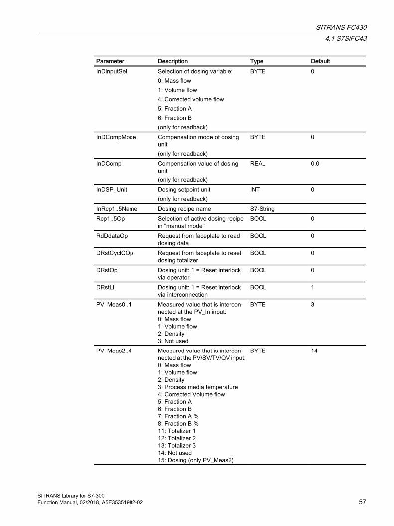
Parameter Description Type DefaultInDinputSel Selection of dosing variable:
0: Mass flow1: Volume flow4: Corrected volume flow5: Fraction A 6: Fraction B(only for readback)
BYTE 0
InDCompMode Compensation mode of dosing unit (only for readback)
BYTE 0
InDComp Compensation value of dosing unit(only for readback)
REAL
0.0
InDSP_Unit Dosing setpoint unit(only for readback)
INT 0
InRcp1..5Name Dosing recipe name S7-String Rcp1..5Op Selection of active dosing recipe
in "manual mode"BOOL 0
RdDdataOp Request from faceplate to read dosing data
BOOL 0
DRstCyclCOp Request from faceplate to reset dosing totalizer
BOOL 0
DRstOp Dosing unit: 1 = Reset interlock via operator
BOOL 0
DRstLi Dosing unit: 1 = Reset interlock via interconnection
BOOL 1
PV_Meas0..1 Measured value that is intercon‐nected at the PV_In input:0: Mass flow1: Volume flow2: Density3: Not used
BYTE 3
PV_Meas2..4 Measured value that is intercon‐nected at the PV/SV/TV/QV input:0: Mass flow1: Volume flow2: Density3: Process media temperature4: Corrected Volume flow5: Fraction A6: Fraction B7: Fraction A %8: Fraction B %11: Totalizer 112: Totalizer 213: Totalizer 314: Not used15: Dosing (only PV_Meas2)
BYTE 14
SITRANS FC4304.1 S7SiFC43
SITRANS Library for S7-300Function Manual, 02/2018, A5E35351982-02 57

Parameter Description Type DefaultRdCfgOp 1 = Read all configuration data
from FC430BOOL 0
WrCfgOp 1 = Write all configuration data to FC430
BOOL 0
ZeroAdjOp 1 = Start automatic zero balanc‐ing
BOOL 0
InMflZFSupp Low flow cut-off suppression (mass flow)(only for readback)
REAL 0.0
InVflZFSupp Low flow cut-off suppression (vol‐ume flow)(only for readback)
REAL 0.0
GradHUpEn 1 = Enable gradient monitoring (high) for positive changes
BOOL 1
GradHDnEn 1 = Enable gradient monitoring (high) for negative changes
BOOL 1
GradLEn 1 = Enable gradient monitoring (low)
BOOL 0
GradHUpMsgEn 1 = Enable gradient (high) mes‐sage for positive changes
BOOL 1
GradHDnMsgEn 1 = Enable gradient (high) mes‐sage for negative changes
BOOL 1
GradLMsgEn 1 = Enable gradient (low) mes‐sage for negative changes
BOOL 1
TimeFactor Time unit:0 = seconds1 = minutes2 = hours
INT 0
OnPVOp* 1 = PV "On" mode via operator BOOL 0OosPVOp*(analog SV,TV,QV)
1 = PV "Out of service" via OS operation
BOOL 0
OosPVLi(analog SV,TV,QV)
1 = PV "Out of service" via inter‐connection or SFC (0-1 edge tran‐sition)
BOOL 0
ModSVLiOp(analog TV,QV)
Switchover of SV operating mode between:0 = Operator1 = Interconnection or SFC
BOOL 0
AutModSVOp*(analog TV,QV)
1 = "Automatic mode" SV via op‐erator (controlled by ModLiSVOp = 1)
BOOL 0
ManModSVOp*(analog TV,QV)
Switchover of SV operating mode between:0 = Operator1 = Interconnection or SFC
BOOL 0
SITRANS FC4304.1 S7SiFC43
SITRANS Library for S7-30058 Function Manual, 02/2018, A5E35351982-02
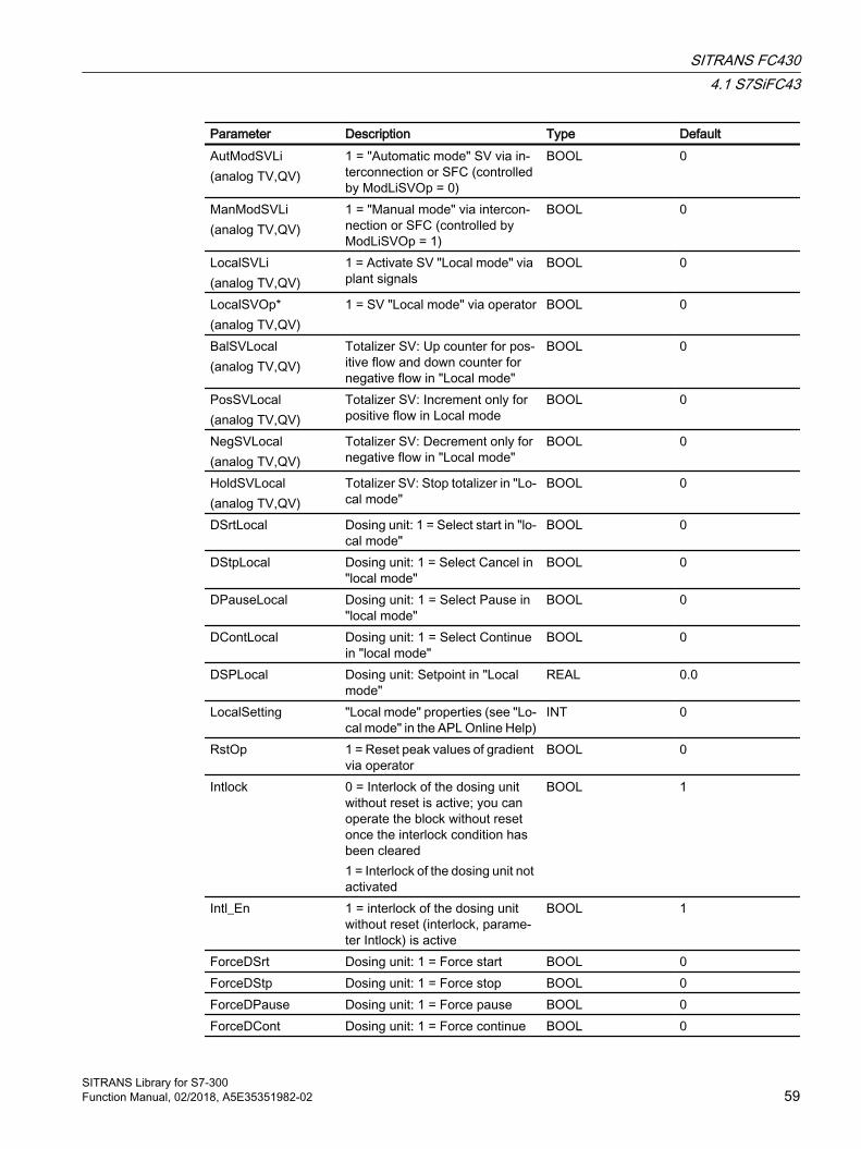
Parameter Description Type DefaultAutModSVLi(analog TV,QV)
1 = "Automatic mode" SV via in‐terconnection or SFC (controlled by ModLiSVOp = 0)
BOOL 0
ManModSVLi(analog TV,QV)
1 = "Manual mode" via intercon‐nection or SFC (controlled by ModLiSVOp = 1)
BOOL 0
LocalSVLi(analog TV,QV)
1 = Activate SV "Local mode" via plant signals
BOOL 0
LocalSVOp*(analog TV,QV)
1 = SV "Local mode" via operator BOOL 0
BalSVLocal(analog TV,QV)
Totalizer SV: Up counter for pos‐itive flow and down counter for negative flow in "Local mode"
BOOL 0
PosSVLocal(analog TV,QV)
Totalizer SV: Increment only for positive flow in Local mode
BOOL 0
NegSVLocal(analog TV,QV)
Totalizer SV: Decrement only for negative flow in "Local mode"
BOOL 0
HoldSVLocal(analog TV,QV)
Totalizer SV: Stop totalizer in "Lo‐cal mode"
BOOL 0
DSrtLocal Dosing unit: 1 = Select start in "lo‐cal mode"
BOOL 0
DStpLocal Dosing unit: 1 = Select Cancel in "local mode"
BOOL 0
DPauseLocal Dosing unit: 1 = Select Pause in "local mode"
BOOL 0
DContLocal Dosing unit: 1 = Select Continue in "local mode"
BOOL 0
DSPLocal Dosing unit: Setpoint in "Local mode"
REAL 0.0
LocalSetting "Local mode" properties (see "Lo‐cal mode" in the APL Online Help)
INT 0
RstOp 1 = Reset peak values of gradient via operator
BOOL 0
Intlock 0 = Interlock of the dosing unit without reset is active; you can operate the block without reset once the interlock condition has been cleared1 = Interlock of the dosing unit not activated
BOOL 1
Intl_En 1 = interlock of the dosing unit without reset (interlock, parame‐ter Intlock) is active
BOOL 1
ForceDSrt Dosing unit: 1 = Force start BOOL 0ForceDStp Dosing unit: 1 = Force stop BOOL 0ForceDPause Dosing unit: 1 = Force pause BOOL 0ForceDCont Dosing unit: 1 = Force continue BOOL 0
SITRANS FC4304.1 S7SiFC43
SITRANS Library for S7-300Function Manual, 02/2018, A5E35351982-02 59

Parameter Description Type DefaultMsgLock 1 = Suppress process messages.
For more information, refer to the "Suppressing messages using the MsgLock parameter" chapter in the APL online Help
BOOL 0
SampleTime Sampling time [s] (assigned auto‐matically)
REAL 0.1
RunUpCyc Number of cycles in startup; mes‐sages are suppressed during these cycles
INT 3
MsgEvId01..25 Message number (assigned auto‐matically)
DWORD 16#00000000
Aux Message Associated Value REAL 0.0BatchEn 1 = Enable allocation BOOL 0BatchID Batch ID DWORD 16#00000000BatchName Batch name S7-String StepNo Batch step number DWORD 16#00000000Occupied 1 = Occupied by batch control BOOL 0CSF 1 = External error (control system
fault)BOOL 0
MsgFilter Message Filter DINT 0CmpID component identifier (not permis‐
sible: 0) Identification of the subsystem to which the message is assigned to Recommended values: ● low word: 1 to 65535● high word: 0
DWORD 16#00000001
PERMIS Switchover of the operator con‐trol permission
INT 2
ExtMsg Binary input for freely selectable message 1
BOOL 0
OS_Perm I/O for operating permissions STRUCT● Bit 0 : BOOL…● Bit31: BOOL
-● 1…● 1
OS1Perm I/O for operating permissions STRUCT● Bit 0 : BOOL…● Bit31: BOOL
-● 1…● 1
OS2Perm I/O for operating permissions STRUCT● Bit 0 : BOOL…● Bit31: BOOL
-● 1…● 1
SITRANS FC4304.1 S7SiFC43
SITRANS Library for S7-30060 Function Manual, 02/2018, A5E35351982-02

Parameter Description Type DefaultOS3Perm I/O for operating permissions STRUCT
● Bit 0 : BOOL…● Bit31: BOOL
-● 1…● 1
Feature I/O for additional functions STRUCT● Bit 0 : BOOL● Bit 1 : BOOL● Bit 2 : BOOL …● Bit 6 : BOOL● Bit 7 : BOOL …● Bit31: BOOL
-● 0● 0● 1 ● 1● 0 ● 0
OldCmdTotSV(analog TV,QV)
Last command of the totalizer SV(only for readback)
BYTE 16#03
OldCmdDosSV Last command of the totalizer SV BYTE 16#03ScaleInH High Range of process value (on‐
ly for read back.REAL
0.0
ScaleInL Low Range of process value (on‐ly for read back)
REAL
0.0
FractnUType Measuring mode for fractions:0: Mass1: Volume
BYTE 16#00
FractnAtxt Name for fraction A (configured in PDM)
S7-String
FractnBtxt Name for fraction B (configured in PDM)
S7-String
Tot1Ch(analog Totalizer 2 und 3)
Process value totalizer 1: 0=Mass flow1=Volume flow4=Corrected volume flow5=Fraction A6=Fraction B)
BYTE 16#00
Ch2HwCnfg Hardware configuration channel 2 (for internal use only)
BYTE 16#00
LimPV_OpScaleH(analog SV,TV,QV)
High limit for warning and alarm limits PV
REAL
1023000.0
LimPV_OpScaleL(analog SV,TV,QV)
Low limit for warning and alarm limits PV
REAL
0.0
SITRANS FC4304.1 S7SiFC43
SITRANS Library for S7-300Function Manual, 02/2018, A5E35351982-02 61
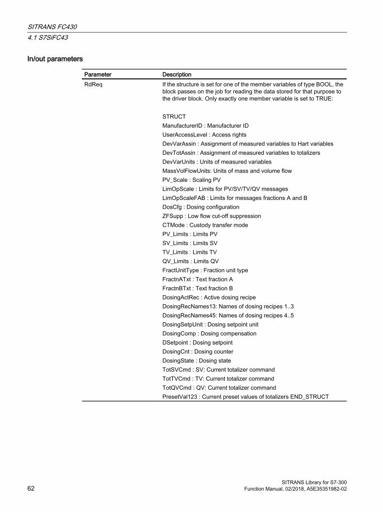
In/out parameters
Parameter DescriptionRdReq If the structure is set for one of the member variables of type BOOL, the
block passes on the job for reading the data stored for that purpose to the driver block. Only exactly one member variable is set to TRUE: STRUCTManufacturerID : Manufacturer IDUserAccessLevel : Access rightsDevVarAssin : Assignment of measured variables to Hart variablesDevTotAssin : Assignment of measured variables to totalizersDevVarUnits : Units of measured variablesMassVolFlowUnits: Units of mass and volume flowPV_Scale : Scaling PVLimOpScale : Limits for PV/SV/TV/QV messagesLimOpScaleFAB : Limits for messages fractions A and BDosCfg : Dosing configurationZFSupp : Low flow cut-off suppressionCTMode : Custody transfer modePV_Limits : Limits PV SV_Limits : Limits SV TV_Limits : Limits TV QV_Limits : Limits QV FractUnitType : Fraction unit typeFractnATxt : Text fraction AFractnBTxt : Text fraction BDosingActRec : Active dosing recipeDosingRecNames13: Names of dosing recipes 1..3DosingRecNames45: Names of dosing recipes 4..5DosingSetpUnit : Dosing setpoint unitDosingComp : Dosing compensationDSetpoint : Dosing setpoint DosingCnt : Dosing counterDosingState : Dosing stateTotSVCmd : SV: Current totalizer commandTotTVCmd : TV: Current totalizer commandTotQVCmd : QV: Current totalizer commandPresetVal123 : Current preset values of totalizers END_STRUCT
SITRANS FC4304.1 S7SiFC43
SITRANS Library for S7-30062 Function Manual, 02/2018, A5E35351982-02
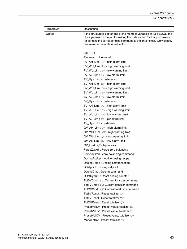
Parameter DescriptionWrReq If the structure is set for one of the member variables of type BOOL, the
block passes on the job for writing the data stored for that purpose or for sending the corresponding command to the driver block. Only exactly one member variable is set to TRUE: STRUCTPassword : PasswordPV_AH_Lim : PV - high alarm limitPV_WH_Lim : PV - high warning limitPV_WL_Lim : PV - low warning limitPV_AL_Lim : PV - low alarm limitPV_Hyst : PV - hysteresisSV_AH_Lim : SV - high alarm limitSV_WH_Lim : SV - high warning limitSV_WL_Lim : SV - low warning limitSV_AL_Lim : SV - low alarm limitSV_Hyst : SV - hysteresisTV_AH_Lim : TV - high alarm limitTV_WH_Lim : TV - high warning limitTV_WL_Lim : TV - low warning limitTV_AL_Lim : TV - low alarm limitTV_Hyst : TV - hysteresisQV_AH_Lim : QV - high alarm limitQV_WH_Lim : QV - high warning limitQV_WL_Lim : QV - low warning limitQV_AL_Lim : QV - low alarm limitQV_Hyst : QV - hysteresisForceZerAdj : Force zero balancingZeroAdjCmd : Zero balancing commandDosingActRec : Active dosing recipeDosingComp : Dosing compensationDSetpoint : Dosing setpoint DosingCmd : Dosing commandDRstCycCnt : Reset dosing counterTotSVCmd : SV: Current totalizer commandTotTVCmd : TV: Current totalizer commandTotQVCmd : QV: Current totalizer commandTotSVReset : Reset totalizer SVTotTVReset : Reset totalizer TVTotQVReset : Reset totalizer QVPresetValSV : Preset value, totalizer SV PresetValTV : Preset value, totalizer TVPresetValQV : Preset value, totalizer QVModeTotSV : Preset totalizer SV
SITRANS FC4304.1 S7SiFC43
SITRANS Library for S7-300Function Manual, 02/2018, A5E35351982-02 63

Parameter DescriptionModeTotTV : Preset totalizer TVModeTotQV : Preset totalizer QV
SITRANS FC4304.1 S7SiFC43
SITRANS Library for S7-30064 Function Manual, 02/2018, A5E35351982-02

Parameter DescriptionPara Values of parameters which are written to the device or read from it:
STRUCTInProcess : Read/write data active _OK : Data successfully read/writtenError : Error when reading/writing dataRdDrErr : Error reading a data recordWrDrErr : Error writing a data recordFractnAtxt : Text fraction AFractnBtxt : Text fraction BInRcp1..5Name : Dosing recipe name 1..5InPassword : PasswordUserAccessLevel : Access rightsPV_Meas0 : Measured value PV_InPV_Meas1 : Measured value PVPV_Meas2 : Measured value SVPV_Meas3 : Measured value TVPV_Meas4 : Measured value QVFractnUType : Measuring mode: (0=mass, 1=volume)Tot1Ch : Measured value totalizer 1Tot2Ch : Measured value totalizer 2Tot3Ch : Measured value totalizer 3SlotHart : Slot of AI Hart moduleSxDC : Internal useCTModeAct: Custody transfer mode activePV_Unit : Unit for PVSV_Unit : Unit for SVTV_Unit : Unit for TVQV_Unit : Unit for QVMfl_Unit : Unit for mass flowVfl_Unit : Unit for volume flowZeroAdjOp : Start zero balancingMflZFSupp : Low flow cut-off suppression for mass flowVflZFSupp : Low flow cut-off suppression for volume flowTot1Cmd : Totalizer command SVTot2Cmd : Totalizer command TVTot3Cmd : Totalizer command QVSVPreVal : Preset value, totalizer SVTVPreVal : Preset value, totalizer TVQVPreVal : Preset value, totalizer QVCh2HwCnfg : BYTE; // channel 2 hardware configurationDMode : Dosing modeDActRec : Active dosing recipeDCyclCnt : Dosing counter valueDinputSel : Measured variable of dosing value
SITRANS FC4304.1 S7SiFC43
SITRANS Library for S7-300Function Manual, 02/2018, A5E35351982-02 65
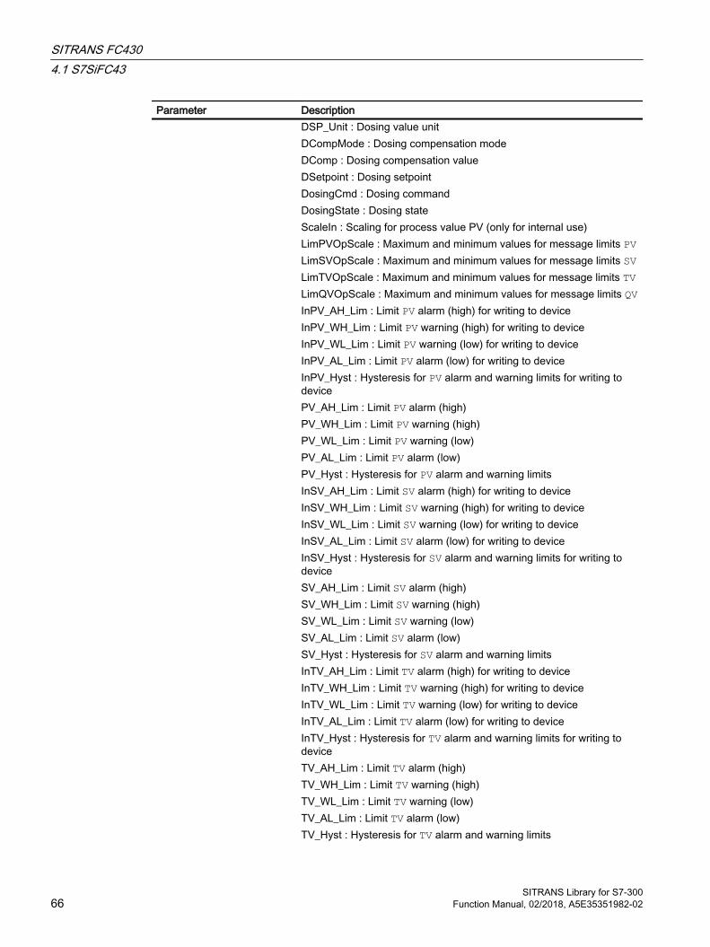
Parameter DescriptionDSP_Unit : Dosing value unitDCompMode : Dosing compensation modeDComp : Dosing compensation value DSetpoint : Dosing setpoint DosingCmd : Dosing commandDosingState : Dosing stateScaleIn : Scaling for process value PV (only for internal use)LimPVOpScale : Maximum and minimum values for message limits PVLimSVOpScale : Maximum and minimum values for message limits SVLimTVOpScale : Maximum and minimum values for message limits TVLimQVOpScale : Maximum and minimum values for message limits QVInPV_AH_Lim : Limit PV alarm (high) for writing to deviceInPV_WH_Lim : Limit PV warning (high) for writing to deviceInPV_WL_Lim : Limit PV warning (low) for writing to deviceInPV_AL_Lim : Limit PV alarm (low) for writing to deviceInPV_Hyst : Hysteresis for PV alarm and warning limits for writing to devicePV_AH_Lim : Limit PV alarm (high) PV_WH_Lim : Limit PV warning (high)PV_WL_Lim : Limit PV warning (low)PV_AL_Lim : Limit PV alarm (low)PV_Hyst : Hysteresis for PV alarm and warning limitsInSV_AH_Lim : Limit SV alarm (high) for writing to deviceInSV_WH_Lim : Limit SV warning (high) for writing to deviceInSV_WL_Lim : Limit SV warning (low) for writing to deviceInSV_AL_Lim : Limit SV alarm (low) for writing to deviceInSV_Hyst : Hysteresis for SV alarm and warning limits for writing to deviceSV_AH_Lim : Limit SV alarm (high) SV_WH_Lim : Limit SV warning (high)SV_WL_Lim : Limit SV warning (low)SV_AL_Lim : Limit SV alarm (low)SV_Hyst : Hysteresis for SV alarm and warning limitsInTV_AH_Lim : Limit TV alarm (high) for writing to deviceInTV_WH_Lim : Limit TV warning (high) for writing to deviceInTV_WL_Lim : Limit TV warning (low) for writing to deviceInTV_AL_Lim : Limit TV alarm (low) for writing to deviceInTV_Hyst : Hysteresis for TV alarm and warning limits for writing to deviceTV_AH_Lim : Limit TV alarm (high) TV_WH_Lim : Limit TV warning (high)TV_WL_Lim : Limit TV warning (low)TV_AL_Lim : Limit TV alarm (low)TV_Hyst : Hysteresis for TV alarm and warning limits
SITRANS FC4304.1 S7SiFC43
SITRANS Library for S7-30066 Function Manual, 02/2018, A5E35351982-02

Parameter DescriptionInQV_AH_Lim : Limit QV alarm (high) for writing to deviceInQV_WH_Lim : Limit QV warning (high) for writing to deviceInQV_WL_Lim : Limit QV warning (low) for writing to deviceInQV_AL_Lim : Limit QV alarm (low) for writing to deviceInQV_Hyst : Hysteresis for QV alarm and warning limits for writing to deviceQV_AH_Lim : Limit QV alarm (high) QV_WH_Lim : Limit QV warning (high)QV_WL_Lim : Limit QV warning (low)QV_AL_Lim : Limit QV alarm (low)QV_Hyst : Hysteresis for QV alarm and warning limits
Parameter Description Type DefaultAcyclData Acyclic data from driver block PiDr64 (in‐
terconnect this input with AcyclData out‐put of PiDr64)
STRUCT● SlotRd : INT● …● RetValWr:
WORD● Input : STRUCT● Output :
STRUCT● NewDiag : INT● DiagData :
STRUCT
Output parameters
Parameter Description Type DefaultQWronDev 1 = Wrong device connected BOOL 1PV_Out0..4 Process value output PV_In/PV/SV/
TV/QVSTRUCT ● Value : BYTE ● ST : BYTE
0.0
SVPreVal(analog TV,QV)
Preset value, totalizer SV REAL
0.0
PV_Grad Gradient value for process value PV REAL
0.0
PV_GradPP Gradient value for PV maximum peak value
REAL
0.0
PV_GradNP Gradient value for PV minimum peak value
REAL
0.0
SITRANS FC4304.1 S7SiFC43
SITRANS Library for S7-300Function Manual, 02/2018, A5E35351982-02 67

Parameter Description Type DefaultGradHUpAct 1 = Gradient alarm (high) for positive
changes. 1 = Alarm (low) active. You can change the response for this parameter by setting Feature bit 28 (de‐activate switching points) and Feature bit 29 (high/low signal limit violation) ac‐cordingly.
BOOL 0
GradHDnAct 1 = Gradient alarm (high) for negative changes. 1 = Alarm (low) active. You can change the response for this parameter by setting Feature bit 28 (de‐activate switching points) and Feature bit 29 (high/low signal limit violation) ac‐cordingly.
BOOL 0
GradHLAct 1 = Gradient alarm (low). 1 = Alarm (low) active. You can change the response for this parameter by setting Feature bit 28 (de‐activate switching points) and Feature bit 29 (high/low signal limit violation) ac‐cordingly.
BOOL 0
CmdTotSV(analog TV,QV)
Current command totalizer SV:● 16#00: Up counter for positive flow
and down counter for negative flow● 16#01: Only up counter for positive
flow● 16#02: Only down counter for
negative flow● 16#03: Stop totalizer
BYTE 16#03
CmdDosSV Current command dosing unit:● 16#01: Start ● 16#02: Stop ● 16#03: Pause● 16#04: Resume● 16#05: Cleaning program
BYTE 16#00
ModeTotSV(analog TV,QV)
0 : Totalizer mode2 : Use preset value
BYTE 16#03
DActRec Active dosing recipe (1..5) BYTE 16#00DCyclCnt Dosing cycle counter DWORD 0DinputSel Selection of dosing variable:
0: Mass flow1: Volume flow4: Corrected volume flow5: Fraction A 6: Fraction B
BYTE 0
SITRANS FC4304.1 S7SiFC43
SITRANS Library for S7-30068 Function Manual, 02/2018, A5E35351982-02
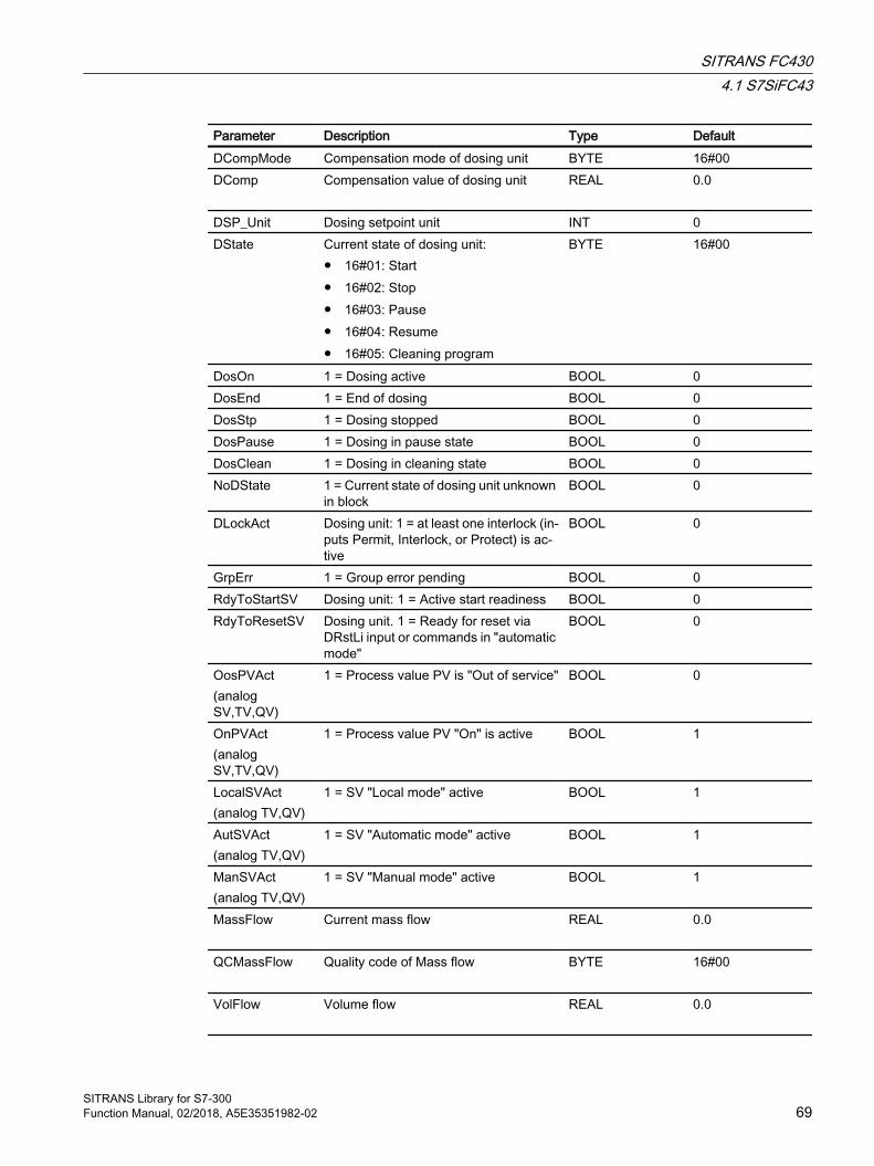
Parameter Description Type DefaultDCompMode Compensation mode of dosing unit BYTE 16#00DComp Compensation value of dosing unit REAL
0.0
DSP_Unit Dosing setpoint unit INT 0DState Current state of dosing unit:
● 16#01: Start ● 16#02: Stop ● 16#03: Pause● 16#04: Resume● 16#05: Cleaning program
BYTE 16#00
DosOn 1 = Dosing active BOOL 0DosEnd 1 = End of dosing BOOL 0DosStp 1 = Dosing stopped BOOL 0DosPause 1 = Dosing in pause state BOOL 0DosClean 1 = Dosing in cleaning state BOOL 0NoDState 1 = Current state of dosing unit unknown
in blockBOOL 0
DLockAct Dosing unit: 1 = at least one interlock (in‐puts Permit, Interlock, or Protect) is ac‐tive
BOOL 0
GrpErr 1 = Group error pending BOOL 0RdyToStartSV Dosing unit: 1 = Active start readiness BOOL 0RdyToResetSV Dosing unit. 1 = Ready for reset via
DRstLi input or commands in "automatic mode"
BOOL 0
OosPVAct(analog SV,TV,QV)
1 = Process value PV is "Out of service"
BOOL 0
OnPVAct(analog SV,TV,QV)
1 = Process value PV "On" is active BOOL 1
LocalSVAct(analog TV,QV)
1 = SV "Local mode" active BOOL 1
AutSVAct(analog TV,QV)
1 = SV "Automatic mode" active BOOL 1
ManSVAct(analog TV,QV)
1 = SV "Manual mode" active BOOL 1
MassFlow Current mass flow REAL
0.0
QCMassFlow Quality code of Mass flow BYTE
16#00
VolFlow Volume flow REAL
0.0
SITRANS FC4304.1 S7SiFC43
SITRANS Library for S7-300Function Manual, 02/2018, A5E35351982-02 69
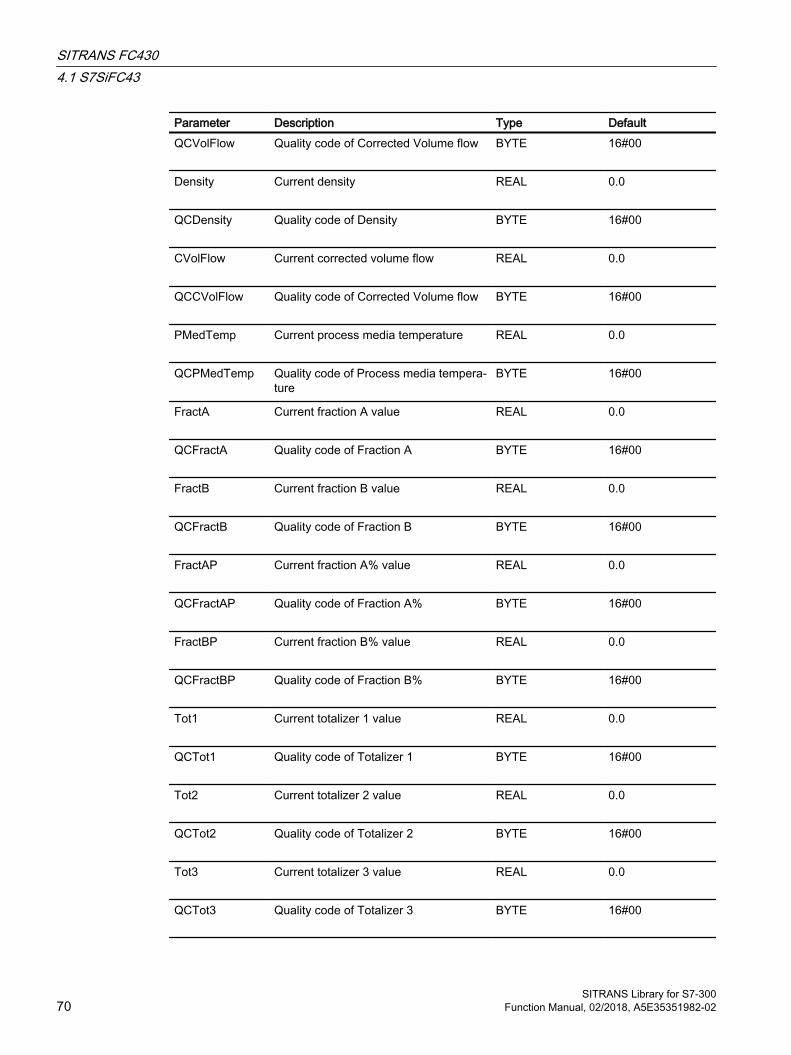
Parameter Description Type DefaultQCVolFlow Quality code of Corrected Volume flow BYTE
16#00
Density Current density REAL
0.0
QCDensity Quality code of Density BYTE
16#00
CVolFlow Current corrected volume flow REAL
0.0
QCCVolFlow Quality code of Corrected Volume flow BYTE
16#00
PMedTemp Current process media temperature REAL
0.0
QCPMedTemp Quality code of Process media tempera‐ture
BYTE
16#00
FractA Current fraction A value REAL
0.0
QCFractA Quality code of Fraction A BYTE
16#00
FractB Current fraction B value REAL
0.0
QCFractB Quality code of Fraction B BYTE
16#00
FractAP Current fraction A% value REAL
0.0
QCFractAP Quality code of Fraction A% BYTE
16#00
FractBP Current fraction B% value REAL
0.0
QCFractBP Quality code of Fraction B% BYTE
16#00
Tot1 Current totalizer 1 value REAL
0.0
QCTot1 Quality code of Totalizer 1 BYTE
16#00
Tot2 Current totalizer 2 value REAL
0.0
QCTot2 Quality code of Totalizer 2 BYTE
16#00
Tot3 Current totalizer 3 value REAL
0.0
QCTot3 Quality code of Totalizer 3 BYTE
16#00
SITRANS FC4304.1 S7SiFC43
SITRANS Library for S7-30070 Function Manual, 02/2018, A5E35351982-02
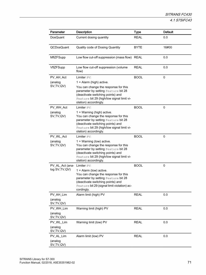
Parameter Description Type DefaultDosQuant Current dosing quantity REAL
0.0
QCDosQuant Quality code of Dosing Quantity BYTE
16#00
MflZFSupp Low flow cut-off suppression (mass flow) REAL
0.0
VflZFSupp Low flow cut-off suppression (volume flow)
REAL
0.0
PV_AH_Act(analog SV,TV,QV)
Limiter PV:1 = Alarm (high) active. You can change the response for this parameter by setting Feature bit 28 (deactivate switching points) and Feature bit 29 (high/low signal limit vi‐olation) accordingly.
BOOL 0
PV_WH_Act(analog SV,TV,QV)
Limiter PV:1 = Warning (high) active. You can change the response for this parameter by setting Feature bit 28 (deactivate switching points) and Feature bit 29 (high/low signal limit vi‐olation) accordingly.
BOOL 0
PV_WL_Act(analog SV,TV,QV)
Limiter PV:1 = Warning (low) active. You can change the response for this parameter by setting Feature bit 28 (deactivate switching points) and Feature bit 29 (high/low signal limit vi‐olation) accordingly.
BOOL 0
PV_AL_Act (ana‐log SV,TV,QV)
Limiter PV:1 = Alarm (low) active. You can change the response for this parameter by setting Feature bit 28 (deactivate switching points) and Feature bit 29 (signal limit violation) ac‐cordingly.
BOOL 0
PV_AH_Lim(analog SV,TV,QV)
Alarm limit (high) PV REAL
0.0
PV_WH_Lim(analog SV,TV,QV)
Warning limit (high) PV REAL
0.0
PV_WL_Lim(analog SV,TV,QV)
Warning limit (low) PV REAL
0.0
PV_AL_Lim(analog SV,TV,QV)
Alarm limit (low) PV REAL
0.0
SITRANS FC4304.1 S7SiFC43
SITRANS Library for S7-300Function Manual, 02/2018, A5E35351982-02 71
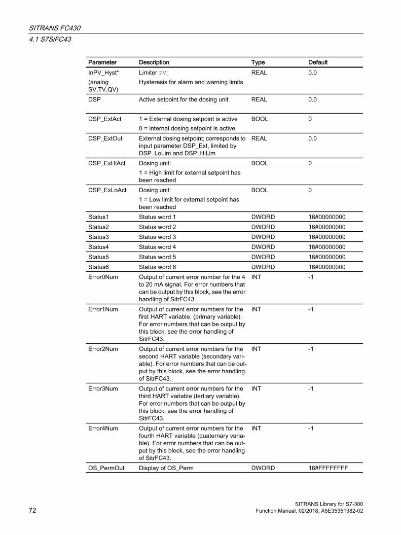
Parameter Description Type DefaultInPV_Hyst*(analog SV,TV,QV)
Limiter PV:Hysteresis for alarm and warning limits
REAL 0.0
DSP Active setpoint for the dosing unit REAL
0.0
DSP_ExtAct 1 = External dosing setpoint is active0 = internal dosing setpoint is active
BOOL 0
DSP_ExtOut External dosing setpoint; corresponds to input parameter DSP_Ext, limited by DSP_LoLim and DSP_HiLim
REAL
0.0
DSP_ExHiAct Dosing unit:1 = High limit for external setpoint has been reached
BOOL 0
DSP_ExLoAct Dosing unit:1 = Low limit for external setpoint has been reached
BOOL 0
Status1 Status word 1 DWORD 16#00000000Status2 Status word 2 DWORD 16#00000000Status3 Status word 3 DWORD 16#00000000Status4 Status word 4 DWORD 16#00000000Status5 Status word 5 DWORD 16#00000000Status6 Status word 6 DWORD 16#00000000Error0Num Output of current error number for the 4
to 20 mA signal. For error numbers that can be output by this block, see the error handling of SitrFC43.
INT -1
Error1Num Output of current error numbers for the first HART variable. (primary variable). For error numbers that can be output by this block, see the error handling of SitrFC43.
INT -1
Error2Num Output of current error numbers for the second HART variable (secondary vari‐able). For error numbers that can be out‐put by this block, see the error handling of SitrFC43.
INT -1
Error3Num Output of current error numbers for the third HART variable (tertiary variable). For error numbers that can be output by this block, see the error handling of SitrFC43.
INT -1
Error4Num Output of current error numbers for the fourth HART variable (quaternary varia‐ble). For error numbers that can be out‐put by this block, see the error handling of SitrFC43.
INT -1
OS_PermOut Display of OS_Perm DWORD 16#FFFFFFFF
SITRANS FC4304.1 S7SiFC43
SITRANS Library for S7-30072 Function Manual, 02/2018, A5E35351982-02

Parameter Description Type DefaultOS_PermLog Display of OS_Perm with settings
changed by the block algorithmDWORD 16#FFFFFFFF
OS1PermOut Display of OS1Perm DWORD 16#FFFFFFFFOS1PermLog Display of OS1Perm with settings
changed by the block algorithmDWORD 16#FFFFFFFF
OS2PermOut Display of OS2Perm DWORD 16#FFFFFFFFOS2PermLog Display of OS2Perm with settings
changed by the block algorithmDWORD 16#FFFFFFFF
OS3PermOut Display of OS3Perm DWORD 16#FFFFFFFFOS3PermLog Display of OS3Perm with settings
changed by the block algorithmDWORD 16#FFFFFFFF
MsgErr1 1 = Message error 1 (ERROR output of first ALARM_8P)
BOOL 0
MsgStat1..25 Alarm status 1 (output ERROR of first ALARM_8P)
WORD 16#0000
MsgAckn1..25 Alarm acknowledgment status 1 (STA‐TUS output of first ALARM_8P)
WORD 16#0000
ScaleOutH High Range of process value (PV_OUT0)
REAL
0.0
ScaleOutL Low Range of process value (PV_OUT0) REAL
0.0
4.1.7 Block diagram of S7SiFC43A block diagram is not provided for this block.
4.1.8 Template of S7SiFC43This process tag type is used to connect a Sitrans FC430 with SCALING blocks to STEP 7 with or without dosing function (template 'Sitrans FC430 Dosing' and 'Sitrans FC430' respectively).
Note
The SCALE function takes an integer value (IN) and converts it to a real value in engineering units scaled between a low and a high limit (LO_LIM and HI_LIM). For more information on Scaling block press F1 for online help.
The Scaling block trims the value of PVin and SV 4 to 20 mA signal.The inputs for the Hart auxiliary variables of the function block S7SiFC43 (PV, SV, TV, QV) are interconnected with the corresponding input from HW Config.
The inputs Laddr, Addr.Laddr0 and Addr.Laddr1 of the PiDr64 block (AcyclicData) are configured with the address of the process value PV (not interconnected!).
SITRANS FC4304.1 S7SiFC43
SITRANS Library for S7-300Function Manual, 02/2018, A5E35351982-02 73
The slot of the AI module is configured within ET200M at the SlotHart input (see HW Config). The Feature bit 14 is used to configure whether the dosing function is used.
4.1.9 Operator control and monitoring
4.1.9.1 S7SiFC43 views
Views of the S7SiFC43 blockThe S7SiFC43 block has the following views:
● Standard view of S7SiFC43 (Page 74)
● Message view (see the APL Online Help)
● Limit view of S7SiFC43 (Page 80)
● Trend view (see the APL Online Help)
● Parameter view of S7SiFC43 (Page 85)
● Preview of S7SiFC43 (Page 87)
● Batch view (see the APL Online Help)
● Dosing view of S7SiFC43 (Page 92)
For general information on the faceplate and block icon, refer to the sections "Faceplate structure" and "Block icon structure" in the APL Online Help.
4.1.9.2 Standard view of S7SiFC43The current process values for mass flow, volume flow, density, process media temperature, corrected volume flow, fraction A or B, fraction A or B in percent, or counter 1, 2 or 3 are displayed in the standard view depending on the configuration of the process value and the Hart auxiliary variables. If a measured value is not assigned to a variable, the field is hidden. The gradient values always refer to the process value PV_In. The standard view is divided into two parts.
Note
The following screenshots show a sample configuration for SV (dosing), TV (measured value) and QV (totalizer). The structure of the faceplate is always based on the individual configuration in PDM.
SITRANS FC4304.1 S7SiFC43
SITRANS Library for S7-30074 Function Manual, 02/2018, A5E35351982-02
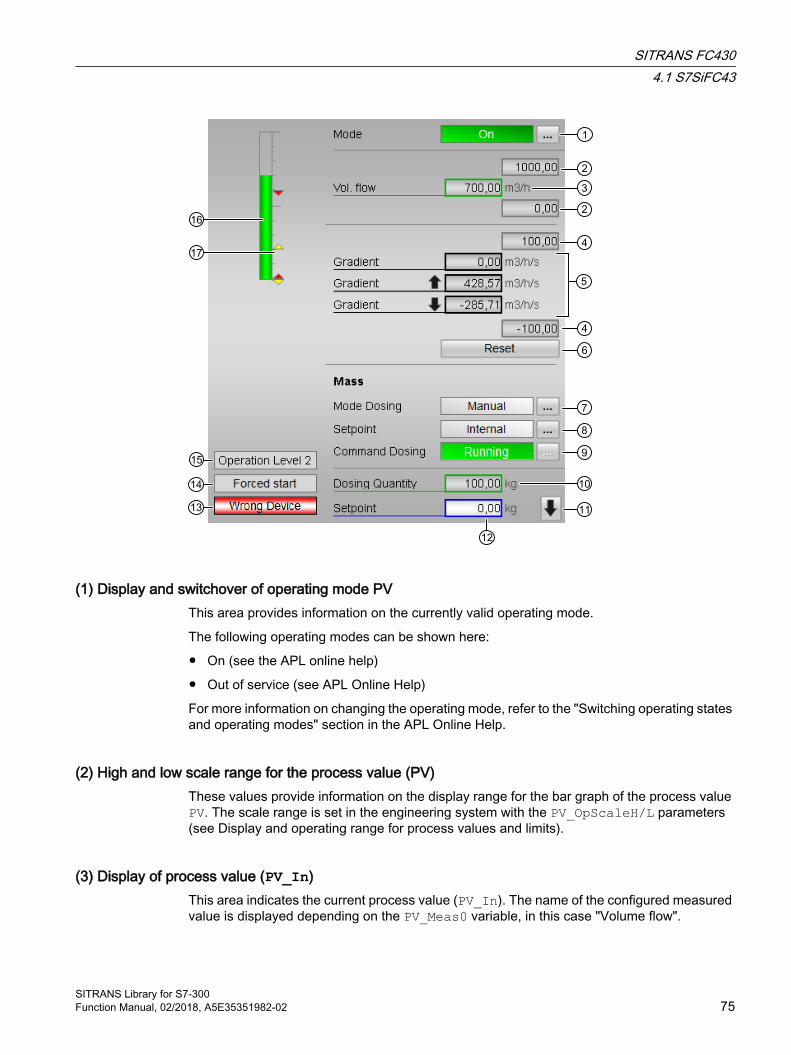
(1) Display and switchover of operating mode PVThis area provides information on the currently valid operating mode.
The following operating modes can be shown here:
● On (see the APL online help)
● Out of service (see APL Online Help)
For more information on changing the operating mode, refer to the "Switching operating states and operating modes" section in the APL Online Help.
(2) High and low scale range for the process value (PV)These values provide information on the display range for the bar graph of the process value PV. The scale range is set in the engineering system with the PV_OpScaleH/L parameters (see Display and operating range for process values and limits).
(3) Display of process value (PV_In)This area indicates the current process value (PV_In). The name of the configured measured value is displayed depending on the PV_Meas0 variable, in this case "Volume flow".
SITRANS FC4304.1 S7SiFC43
SITRANS Library for S7-300Function Manual, 02/2018, A5E35351982-02 75

(4) High and low scale range for the gradient valueThese values provide information on the display range for the bar graph of the gradient. The scale range corresponds to 10% of the scale range for the process value (PV): If you have entered a scale range for the process value of 0 to 100, for example, the scale range for the gradient is automatically defined as -10 to 10.
The current gradient value is displayed if one of the monitoring functions is enabled:
● Gradient monitoring for positive changes (GradHUpEn = 1)
● Gradient monitoring for negative changes (GradHDnEn = 1)
● Gradient monitoring (GradLEn = 1)
(5) Display of gradientThis area shows the current, minimum and maximum gradient values of the process value PV as well as rising and falling of the value. This display of the minimum and maximum gradient values functions like a slave pointer.
The current gradient value is displayed if one of the monitoring functions is enabled:
● Gradient monitoring for positive changes (GradHUpEn = 1)
● Gradient monitoring for negative changes (GradHDnEn = 1)
● Gradient monitoring (GradLEn = 1)
The maximum peak gradient value is displayed if the gradient monitoring function for positive changes is enabled (GradHUpEn = 1)
The minimum peak gradient value is displayed if the gradient monitoring function for negative changes is enabled (GradHDnEn = 1)
(6) Resetting of peak values of the gradientUsing these buttons you can reset the maximum or minimum peak value of the gradient (output parameters PV_GradPP and PV_GradNP).
The button is displayed if the gradient monitoring function for positive (GradHUpEn = 1) or negative (GradHDnEn = 1) changes is enabled.
(7) Display and switchover of operating mode SVThis area provides information on the currently valid operating mode. The operating mode switchover depends on whether or not a totalizer or dosing is configured.
The following operating modes can be shown here:
Without totalizer/dosing:
The following operating modes can be shown here:
● On (see the APL online help)
● Out of service (see APL Online Help)
With totalizer or dosing:
SITRANS FC4304.1 S7SiFC43
SITRANS Library for S7-30076 Function Manual, 02/2018, A5E35351982-02
The block can be operated using the following modes:
● Local mode
● Automatic mode
● Manual mode
● Out of service
For more information on changing the operating mode, refer to the "Switching operating states and operating modes" section in the APL Online Help.
(8) Display and change the setpoint if dosing is configuredThe following states can be shown and changed here:
● "Internal"
● "External"
For more information, refer to the "Manual and automatic mode for motors, valves and dosing units" section in the APL Online Help.
(9) Display and change the dosing unit: Start, resume, pause and stopThis area shows you the default operating state for the dosing unit. The following states can be shown and changed here:
● "Start"
● "Continue"
● "Pause"
● "Stop"
(10) Display of the dosed quantityThis area provides information on the currently dosed quantity.
(11) Change to second standard viewThe second part of the two-part standard view of the faceplate can be selected here.
(12) Display and change the setpointThis area displays the current dosing unit setpoint and lets you edit the setpoint in manual mode.
SITRANS FC4304.1 S7SiFC43
SITRANS Library for S7-300Function Manual, 02/2018, A5E35351982-02 77

(13) and (14) Display area for block statesThis area provides additional information on the operating state of the block:
● Forced control of dosing unit: "Forced start"/"Resume"/"Pause"/"Stop"
● "Wrong device"
(15) Display area for switch permissionThis area provides the text of the current OS, according to the enumeration configured at the PERMIS input.
(16) Bar graph for the "process value" (PV)This area shows the current "process value" (PV) in the form of a bar graph. The visible area in the bar graph depends on the configuration in the engineering system (ES), see Display and operating range for process values and limits.
(17) Limit displayThese small, colored triangles indicate the specified limits of the process value PV in the bar graph.
Second standard view
(1) Change to first standard viewThe first part of the two-part standard view of the faceplate can be selected here.
SITRANS FC4304.1 S7SiFC43
SITRANS Library for S7-30078 Function Manual, 02/2018, A5E35351982-02

(2) Display of process value (PV)This area indicates the current process value (PV). The name of the configured measured value is displayed depending on the PV_Meas1 variable, in this case "Mass flow".
(3) Display and switchover of operating mode TVThis area provides information on the currently valid operating mode. The operating mode switchover depends on whether or not a totalizer is configured.
The following operating modes can be shown here:
Without totalizer:
The following operating modes can be shown here:
● On (see the APL online help)
● Out of service (see APL Online Help)
With totalizer:
The block can be operated using the following modes:
● Local mode
● Automatic mode
● Manual mode
● Out of service
(4) Display of process value (TV)This area indicates the current process value (TV). The name of the configured measured value is displayed depending on the PV_Meas2 variable, in this case "Volume flow ".
(5) Display and switchover of operating mode QVThis area provides information on the currently valid operating mode. The operating mode switchover depends on whether or not a totalizer is configured.
The following operating modes can be shown here:
Without totalizer:
The following operating modes can be shown here:
● On (see the APL online help)
● Out of service (see APL Online Help)
With totalizer:
The block can be operated using the following modes:
● Local mode
● Automatic mode
SITRANS FC4304.1 S7SiFC43
SITRANS Library for S7-300Function Manual, 02/2018, A5E35351982-02 79

● Manual mode
● Out of service
(6) Display and change the totalizer command QV: Positive and negative, positive, negative and holdThis area shows you the default operating state for the totalizer QV. The following states can be shown and executed here:
● "Positive and negative"
● "Positive"
● "Negative"
● "Hold"
If a totalizer is not configured, the area is switched to invisible.
(7) Reset totalizerReset the totalizer value to zero here.
(8) Display of the totalizer value This area shows the current totalizer value of a configured totalizer.
(9) Display area for switch permissionThis area provides the text of the current OS, according to the enumeration configured at the PERMIS input.
4.1.9.3 Limit view of S7SiFC43The limits of the process and totalizer values can specified in this view. The displayed texts depend on the configuration of the process values PV, SV, TV and QV.
Note
If the Feature bit 7 (synchronize alarm configuration with module) is set, the measuring range limits available in the module are written to the corresponding inputs when reading the configuration data.
If a process value is not configured, its limits are switched to invisible.
SITRANS FC4304.1 S7SiFC43
SITRANS Library for S7-30080 Function Manual, 02/2018, A5E35351982-02

(1) Process value limits PVIn this area, you can enter the limits for the process value PV. You can change the following limits:
● "HH alarm": High alarm
● "H warning": High warning
● "Hysteresis"
● "L warning": Low warning
● "LL alarm": Low alarm
(2) Process value limits SVIn this area, you can enter the limits for the process value SV. You can change the following limits:
● "HH alarm": High alarm
● "H warning": High warning
● "Hysteresis"
SITRANS FC4304.1 S7SiFC43
SITRANS Library for S7-300Function Manual, 02/2018, A5E35351982-02 81
● "L warning": Low warning
● "LL alarm": Low alarm
(3) Gradient limitsYou can enter gradient limits in this area. Refer to the "Changing values" section in the APL Online Help.
You can change the following limits:
● "H alarm ⇑": Gradient for the upper gradient for positive changes
● "H alarm ⇓": Gradient for the upper rate of rise for negative changes
● "L alarm ⇑⇓": Gradient for the lower rate of rise (absolute)
(4) Change to second limit viewThe second part of the two-part limit view of the faceplate can be selected here.
(5) Enabled operationsThis area shows all operations for which special operator authorizations are assigned. They depend on the configuration in the engineering system (ES) that applies to this block.
Symbols for enabled operations:
● Green check mark: The OS operator can control this parameter
● Gray check mark: the OS operator cannot control this parameter at this time due to the process
● Red cross: The OS operator cannot control this parameter due to the configured AS operator permissions (OS_Perm or OS1Perm)
(6) Suppress messagesYou can activate/deactivate messages by selecting the check mark.
(7) PasswordA password must be entered before message limits can be changed in the device; this is entered here.
SITRANS FC4304.1 S7SiFC43
SITRANS Library for S7-30082 Function Manual, 02/2018, A5E35351982-02

Second limit view
(1) Change to first limit viewThe first part of the two-part limit view of the faceplate can be selected here.
(2) Process value limits TVIn this area, you can enter the limits for the process value TV. You can change the following limits:
● "HH alarm": High alarm
● "H warning": High warning
● "Hysteresis"
● "L warning": Low warning
● "LL alarm": Low alarm
(3) Process value limits QVIn this area, you can enter the limits for the process value QV. You can change the following limits:
● "HH alarm": High alarm
● "H warning": High warning
● "Hysteresis"
SITRANS FC4304.1 S7SiFC43
SITRANS Library for S7-300Function Manual, 02/2018, A5E35351982-02 83
● "L warning": Low warning
● "LL alarm": Low alarm
(4) PasswordA password must be entered before message limits can be changed in the device; this is entered here.
(5) Enabled operationsThis area shows all operations for which special operator authorizations are assigned. They depend on the configuration in the engineering system (ES) that applies to this block.
Symbols for enabled operations:
● Green check mark: The OS operator can control this parameter
● Gray check mark: the OS operator cannot control this parameter at this time due to the process
● Red cross: The OS operator cannot control this parameter due to the configured AS operating permissions (OS_Perm or OS1Perm)
(6) Suppress messagesYou can activate/deactivate messages by selecting the check mark.
SITRANS FC4304.1 S7SiFC43
SITRANS Library for S7-30084 Function Manual, 02/2018, A5E35351982-02
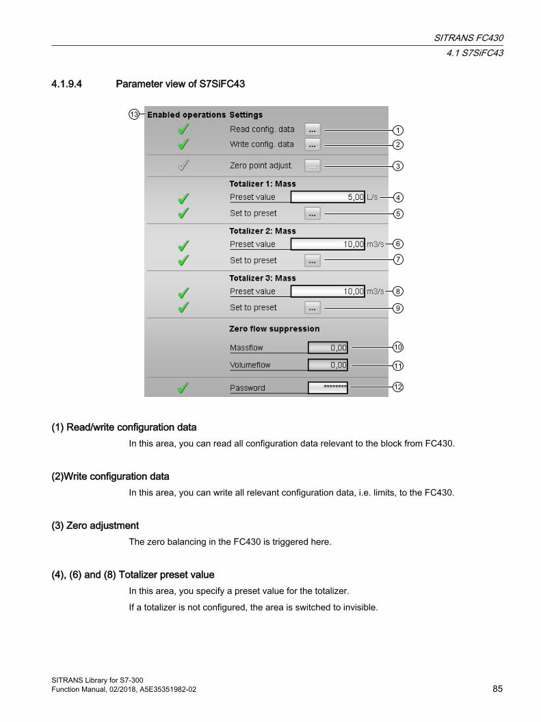
4.1.9.4 Parameter view of S7SiFC43
(1) Read/write configuration dataIn this area, you can read all configuration data relevant to the block from FC430.
(2)Write configuration dataIn this area, you can write all relevant configuration data, i.e. limits, to the FC430.
(3) Zero adjustmentThe zero balancing in the FC430 is triggered here.
(4), (6) and (8) Totalizer preset valueIn this area, you specify a preset value for the totalizer.
If a totalizer is not configured, the area is switched to invisible.
SITRANS FC4304.1 S7SiFC43
SITRANS Library for S7-300Function Manual, 02/2018, A5E35351982-02 85

(5), (7) and (9) Set totalizer preset value In this area, you can set the totalizers to the preset value with the click of a button.
If a totalizer is not configured, the area is switched to invisible.
(10) and (11) Low flow cut-off suppressionThe low flow cut-off suppression for mass and volume flows is displayed in this area.
(12) PasswordA password must be entered before message limits can be changed in the device when writing all configuration data; this is entered here.
(13) Enabled operationsThis area shows all operations for which special operator authorizations are assigned. They depend on the configuration in the engineering system (ES) that applies to this block.
Symbols for enabled operations:
● Green check mark: The OS operator can control this parameter
● Gray check mark: the OS operator cannot control this parameter at this time due to the process
● Red cross: The OS operator is generally prohibited from using this parameter due to the configured AS operator control permissions (OS_Perm or OS1Perm)
SITRANS FC4304.1 S7SiFC43
SITRANS Library for S7-30086 Function Manual, 02/2018, A5E35351982-02

4.1.9.5 Preview of S7SiFC43
Note
The following screenshots show a sample configuration for SV (dosing), TV (measured value) and QV (totalizer). The structure of the faceplate is always based on the individual configuration in PDM.
(1) Process value PVThis area displays the real process values PV.
(2) Automatic preview SVThis area shows you the dosing or totalizer command that is input after a switch from "manual mode" to "automatic mode".
If the block is in "automatic mode", the current dosing or totalizer command is displayed.
If a dosing unit or totalizer is not configured, the area is switched to invisible.
SITRANS FC4304.1 S7SiFC43
SITRANS Library for S7-300Function Manual, 02/2018, A5E35351982-02 87
(3) Enabled operations PVThis area shows the operations for the process value PV for which special operating permissions are assigned. They depend on the configuration in the engineering system (ES) that applies to this block.
Symbols for enabled operations:
● Green check mark: The OS operator can control this parameter
● Gray check mark: the OS operator cannot control this parameter at this time due to the process
● Red cross: The OS operator cannot control this parameter due to the configured AS operator permissions (OS_Perm or OS1Perm)
The following enabled operationss are shown here:
● Reset: You can reset the peak value of the gradient.
● "On": You can switch to "On" mode.
● "Out of service": You can switch to "Out of service" mode.
(4) Enabled operations SVThis area shows the operations for the process value SV for which special operating permissions are assigned. They depend on the configuration in the engineering system (ES) that applies to this block.
Symbols for enabled operations:
● Green check mark: The OS operator can control this parameter
● Gray check mark: the OS operator cannot control this parameter at this time due to the process
● Red cross: The OS operator cannot control this parameter due to the configured AS operator permissions (OS_Perm or OS1Perm)
The following enabled operationss are shown here:
General enabled operationss without dosing unit and without totalizer:
● "On": You can switch to "On" mode.
● "Out of service": You can switch to "Out of service" mode.
General enabled operationss with dosing unit or totalizer:
● "Automatic": You can switch to "automatic mode".
● "Manual": You can switch to "manual mode".
● "Local": You can switch to "local mode".
● "Out of service": You can switch to "Out of service" mode.
Totalizer:
● "Start Pos./Neg": You can start the totalizer in positive and negative modes.
● "Start Positive": You can start the totalizer in positive mode.
● "Start Negative": You can start the totalizer in negative mode.
SITRANS FC4304.1 S7SiFC43
SITRANS Library for S7-30088 Function Manual, 02/2018, A5E35351982-02

● "Hold": You can stop the totalizer.
● "Reset": You can reset the totalizer.
Dosing:
● "Start dosing": You can start the dosing procedure.
● "Pause dosing": You can pause the dosing procedure.
● "Resume dosing": You can resume the dosing procedure after a pause or cancellation.
● "Stop dosing": You can cancel the dosing procedure.
● "Start cleaning": You can start the cleaning program.
● "External dosing SP": You can use the external setpoint.
● "Internal dosing SP": You can use the internal setpoint.
● "Dosing SP Change": You can change the setpoint.
● "Reset": You can reset the dosing quantity.
(5) Display current control signalsOnly if dosing is configured:
"Interlock": 0 = Interlocking without reset is active; you can operate the block without reset once the interlocking condition has disappeared 1 = Good state
(6) Display current control signalsThis area shows the most important parameters for this block with the current selection:
Dosing unit:
● "Local dosing": 1 = Control signal for "Local mode" (LocalSVLi) is enabled
● "Local start": 1 = Block is started in "Local mode"
● "Local pause": 1= Dosing paused in "Local mode"
● "Local resume": 1 = Dosing is resumed in "Local mode"
● "Local stop": 1 = Dosing is stopped in "Local mode"
Totalizer:
● "Local tot": 1 = Totalizer is operated in "Local mode"
● "Local P./N. tot": 1 = Totalizer counts positive and negative in "Local mode"
● "Local pos. tot": 1 = Totalizer counts positive in "Local mode"
● "Local Neg. tot": 1 = Totalizer counts negative in "Local mode"
● "Local Neg. Hold": 1 = Totalizer is in hold in "Local mode"
SITRANS FC4304.1 S7SiFC43
SITRANS Library for S7-300Function Manual, 02/2018, A5E35351982-02 89

(7) Change to second previewThe second part of the two-part preview of the faceplate can be selected here.
Second previewThe first part of the two-part preview of the faceplate can be selected here.
(1) Change to first preview
(2) and (3) Automatic preview TV, QVTotalizer:
This area shows you the totalizer command of TV or QV that is input after a switch from "manual mode" to "automatic mode".
If the block is in "automatic mode", the current dosing or totalizer command is displayed.
Measured value:
This area displays the real process value (TV or QV).
SITRANS FC4304.1 S7SiFC43
SITRANS Library for S7-30090 Function Manual, 02/2018, A5E35351982-02
If neither a totalizer nor a measured value is configured, the area is switched to invisible.
(4) and (5) Enabled operations TV, QVThis area shows the operations for the process value TV or QV for which special operating permissions are assigned. They depend on the configuration in the engineering system (ES) that applies to this block.
Symbols for enabled operations:
● Green check mark: The OS operator can control this parameter
● Gray check mark: the OS operator cannot control this parameter at this time due to the process
● Red cross: The OS operator is generally prohibited from using this parameter due to the configured AS operator control permissions (OS_Perm or OS1Perm)
The following enabled operationss are shown here:
Measured value:
● "On": You can switch to "On" mode.
● "Out of service": You can switch to "Out of service" mode.
Totalizer:
● Automatic": You can switch to "automatic mode".
● "Manual": You can switch to "manual mode".
● "Local": You can switch to "local mode".
● "Out of service": You can switch to "Out of service" mode.
● "Start Pos./Neg.": You can start the totalizer in positive and negative modes.
● "Start Positive": You can start the totalizer in positive mode.
● "Start Negative": You can start the totalizer in negative mode.
● "Hold": You can stop the totalizer.
● "Reset": You can reset the totalizer.
(6) Display current control signalsThis area shows the most important parameters for this block with the current selection:
Dosing unit:
● "Local dosing": 1 = Control signal for "Local mode" (LocalSVLi) is enabled
● "Local start": 1 = Block is started in "Local mode"
● "Local pause": 1= Dosing paused in "Local mode"
● "Local resume": 1 = Dosing is resumed in "Local mode"
● "Local stop": 1 = Dosing is stopped in "Local mode"
SITRANS FC4304.1 S7SiFC43
SITRANS Library for S7-300Function Manual, 02/2018, A5E35351982-02 91

Totalizer:
● "Local tot": 1 = Totalizer is operated in "Local mode"
● "Local P./N. tot": 1 = Totalizer counts positive and negative in "Local mode"
● "Local pos. tot": 1 = Totalizer counts positive in "Local mode"
● "Local Neg. tot": 1 = Totalizer counts negative in "Local mode"
● "Local Neg. Hold": 1 = Totalizer is in hold in "Local mode"
4.1.9.6 Dosing view of S7SiFC43The dosing view can only be selected if dosing is configured (Feature bit 14 = TRUE).
(1) Read dosing dataThe "Read dosing data" button is used to read out the following values from the FC430:
● Names of all configured dosing recipes
● Active dosing recipe
● Current dosing setpoint
● Unit of current dosing setpoint
● Current dosing status
● Dosing counter value
● Compensation value of dosing unit
SITRANS FC4304.1 S7SiFC43
SITRANS Library for S7-30092 Function Manual, 02/2018, A5E35351982-02

(2) Active dosing recipeThe active dosing recipe is selected and displayed here.
(3) CompensationDisplay of compensation value for dosing.
(4) Dosing unit cycle counterDisplay of number of dosing cycles carried out since last reset
(5) Reset dosing unit cycle counterReset dosing counter
(6) Display and switchover of dosing operating modeThis area provides information on the currently valid dosing operating mode.
The block can be operated using the following modes:
● Local mode
● Automatic mode
● Manual mode
● Out of service
For more information on changing the operating mode, refer to the "Switching operating states and operating modes" section in the APL Online Help.
(7) Display and change of setpoint if dosing is configuredThe following states can be shown and changed here:
● "Internal"
● "External"
For more information, refer to the "Manual and automatic mode for motors, valves and dosing units" section in the APL Online Help.
(8) Display and change the dosing unit: Start, resume, pause and stopThis area shows you the default operating state for the dosing unit. The following states can be shown and changed here:
● "Start"
● "Continue"
● "Pause"
● "Stop"
SITRANS FC4304.1 S7SiFC43
SITRANS Library for S7-300Function Manual, 02/2018, A5E35351982-02 93
(9) Reset the blockClick "Reset" for interlocks or errors. For more information, refer to the "Resetting the block in case of interlocks or errors" section in the APL Online Help.
(10) Operating area for the interlock functions of the blockYou can use this button to control the interlock functions of the block. For more information, refer to the "Interlocks" section in the APL Online Help.
(11) Display of the dosed quantityThis area provides information on the currently dosed quantity.
(12) Display and change the setpointThis area displays the current dosing unit setpoint and lets you edit the setpoint in manual mode.
(13) and (14) Display area for block statesThis area provides additional information on the operating state of the block:
● "Wrong device"
● Forced control of dosing unit: "Forced start"/"Resume"/"Pause"/"Stop"
(15) Display area for switch permissionThis area provides the text of the current OS, according to the enumeration configured at the PERMIS input.
4.1.9.7 Block icon for S7SiFC43
Block icons for S7SiFC43A variety of block icons are available with the following functions:
● Process tag type
● Limits (high/low)
● Violation of alarm and warning limits as well as the control system fault CSF● Operating modes for PV, SV, TV and QV● Signal status
● Process values (PV_In, SV, TV, QV)
SITRANS FC4304.1 S7SiFC43
SITRANS Library for S7-30094 Function Manual, 02/2018, A5E35351982-02
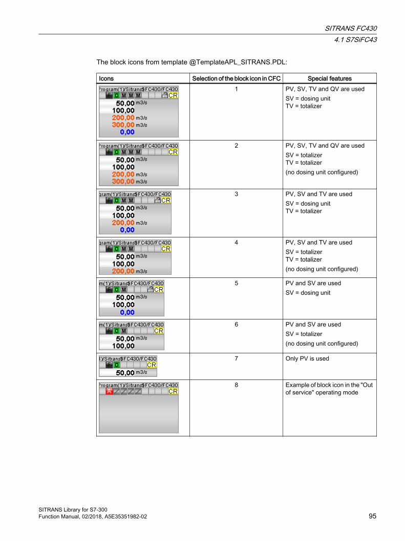
The block icons from template @TemplateAPL_SITRANS.PDL:
Icons Selection of the block icon in CFC Special features1 PV, SV, TV and QV are used
SV = dosing unitTV = totalizer
2 PV, SV, TV and QV are usedSV = totalizerTV = totalizer(no dosing unit configured)
3 PV, SV and TV are usedSV = dosing unitTV = totalizer
4 PV, SV and TV are usedSV = totalizerTV = totalizer(no dosing unit configured)
5 PV and SV are usedSV = dosing unit
6 PV and SV are usedSV = totalizer(no dosing unit configured)
7 Only PV is used
8 Example of block icon in the "Out of service" operating mode
SITRANS FC4304.1 S7SiFC43
SITRANS Library for S7-300Function Manual, 02/2018, A5E35351982-02 95
Additional information on the block icon and the control options in the block icon is available in the following chapters:
● "Configuring the block icons" in the APL Online Help
● "Block icon structure" in the APL Online Help
● "Operation via the block icon" in the APL Online Help
4.2 SiFC43Dr
4.2.1 Description of SiFC43Dr
Object name (type + number) and familyType + number: FB 2631
Family: SiFC43Dr
Application area of SiFC43Dr The block is used for the following application:
● Interface block between the technological block SiFC43Dr and the driver block PiDr64 for reading and writing acyclic data.
How it works The SiFC43Dr block receives requests via its output structures SxRdReq and SxWrReq to read data from the device or to write date to the device. Read data or data to be written is transferred via the Para output structure. The AcyclData input structure serves as an interface via which the read and write jobs are passed on to the PiDr64 driver block.
Configuration The PiDr64, SiFC43Dr and S7SiFC43 blocks are inserted in a cyclic interrupt OB (OB30 to OB38) in exactly the execution sequence. The AcyclData output structure of the PiDr64 block is interconnected to the input with the same name of the SiFC43Dr block. The SxRdReq, SxWrReq and Para output structures of the SiFC43Dr block are interconnected to the RdReq, WrReq and Para inputs of the S7SiFC43 block.
Startup characteristics This block does not have startup characteristics.
SITRANS FC4304.2 SiFC43Dr
SITRANS Library for S7-30096 Function Manual, 02/2018, A5E35351982-02
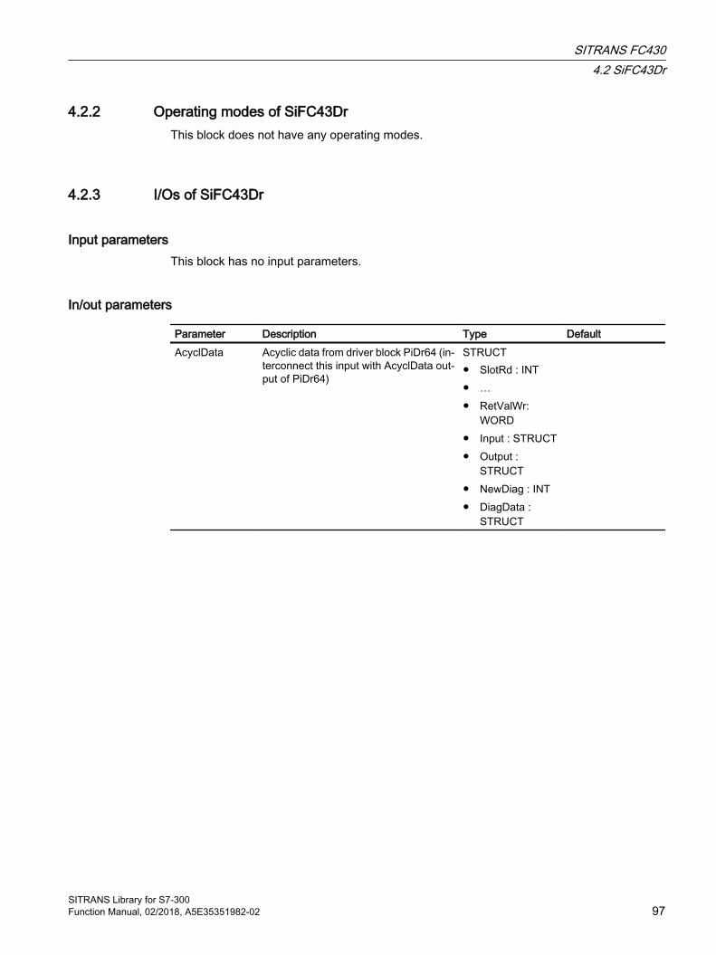
4.2.2 Operating modes of SiFC43DrThis block does not have any operating modes.
4.2.3 I/Os of SiFC43Dr
Input parametersThis block has no input parameters.
In/out parameters
Parameter Description Type DefaultAcyclData Acyclic data from driver block PiDr64 (in‐
terconnect this input with AcyclData out‐put of PiDr64)
STRUCT● SlotRd : INT● …● RetValWr:
WORD● Input : STRUCT● Output :
STRUCT● NewDiag : INT● DiagData :
STRUCT
SITRANS FC4304.2 SiFC43Dr
SITRANS Library for S7-300Function Manual, 02/2018, A5E35351982-02 97

Output parameters
Parameter DescriptionSxRdReq If the structure is set for one of the member variables of type BOOL,
the block passes on the job for reading the data stored for that purpose to the driver block. Only exactly one member variable is set to TRUE: STRUCTManufacturerID : Manufacturer IDUserAccessLevel : Access rightsDevVarAssin : Assignment of measured variables to Hart variablesDevTotAssin : Assignment of measured variables to totalizersDevVarUnits : Units of measured variablesMassVolFlowUnits: Units of mass and volume flowPV_Scale : Scaling PVLimOpScale : Limits for PV/SV/TV/QV messagesLimOpScaleFAB : Limits for messages fractions A and BDosCfg : Dosing configurationZFSupp : Low flow cut-off suppressionCTMode : Custody transfer modePV_Limits : Limits PV SV_Limits : Limits SV TV_Limits : Limits TV QV_Limits : Limits QV FractUnitType : Fraction unit typeFractnATxt : Text fraction AFractnBTxt : Text fraction BDosingActRec : Active dosing recipeDosingRecNames13: Names of dosing recipes 1..3DosingRecNames45: Names of dosing recipes 4..5DosingSetpUnit : Dosing setpoint unitDosingComp : Dosing compensationDSetpoint : Dosing setpoint DosingCnt : Dosing counterDosingState : Dosing stateTotSVCmd : SV: Current totalizer commandTotTVCmd : TV: Current totalizer commandTotQVCmd : QV: Current totalizer commandPresetVal123 : Current preset values of totalizers END_STRUCT
SITRANS FC4304.2 SiFC43Dr
SITRANS Library for S7-30098 Function Manual, 02/2018, A5E35351982-02

Parameter DescriptionSxWrReq If the structure is set for one of the member variables of type BOOL,
the block passes on the job for writing the data stored for that purpose or for sending the corresponding command to the driver block. Only exactly one member variable is set to TRUE: STRUCTPassword : PasswordPV_AH_Lim : PV - High alarm limitPV_WH_Lim : PV - High warning limitPV_WL_Lim : PV - Low warning limitPV_AL_Lim : PV - Low alarm limitPV_Hyst : PV - HysteresisSV_AH_Lim : SV - High alarm limitSV_WH_Lim : SV - High warning limitSV_WL_Lim : SV - Low warning limitSV_AL_Lim : SV - Low alarm limitSV_Hyst : SV - HysteresisTV_AH_Lim : TV - High alarm limitTV_WH_Lim : TV - High warning limitTV_WL_Lim : TV - Low warning limitTV_AL_Lim : TV - Low alarm limitTV_Hyst : TV - HysteresisQV_AH_Lim : QV - High alarm limitQV_WH_Lim : QV - High warning limitQV_WL_Lim : QV - Low warning limitQV_AL_Lim : QV - Low alarm limitQV_Hyst : QV - HysteresisForceZerAdj : Force zero balancingZeroAdjCmd : Zero balancing commandDosingActRec : Active dosing recipeDosingComp : Dosing compensationDSetpoint : Dosing setpoint DosingCmd : Dosing commandDRstCycCnt : Reset dosing counterTotSVCmd : SV: Current totalizer commandTotTVCmd : TV: Current totalizer commandTotQVCmd : QV: Current totalizer commandTotSVReset : Reset totalizer SVTotTVReset : Reset totalizer TVTotQVReset : Reset totalizer QVPresetValSV : Preset value, totalizer SV PresetValTV : Preset value, totalizer TVPresetValQV : Preset value, totalizer QVModeTotSV : Preset totalizer SV
SITRANS FC4304.2 SiFC43Dr
SITRANS Library for S7-300Function Manual, 02/2018, A5E35351982-02 99

Parameter DescriptionModeTotTV : Preset totalizer TVModeTotQV : Preset totalizer QV
SITRANS FC4304.2 SiFC43Dr
SITRANS Library for S7-300100 Function Manual, 02/2018, A5E35351982-02
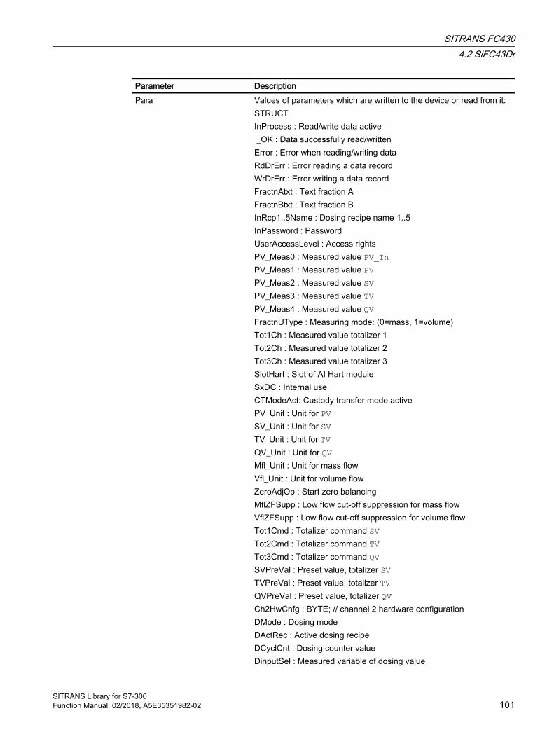
Parameter DescriptionPara Values of parameters which are written to the device or read from it:
STRUCTInProcess : Read/write data active _OK : Data successfully read/writtenError : Error when reading/writing dataRdDrErr : Error reading a data recordWrDrErr : Error writing a data recordFractnAtxt : Text fraction AFractnBtxt : Text fraction BInRcp1..5Name : Dosing recipe name 1..5InPassword : PasswordUserAccessLevel : Access rightsPV_Meas0 : Measured value PV_InPV_Meas1 : Measured value PVPV_Meas2 : Measured value SVPV_Meas3 : Measured value TVPV_Meas4 : Measured value QVFractnUType : Measuring mode: (0=mass, 1=volume)Tot1Ch : Measured value totalizer 1Tot2Ch : Measured value totalizer 2Tot3Ch : Measured value totalizer 3SlotHart : Slot of AI Hart moduleSxDC : Internal useCTModeAct: Custody transfer mode activePV_Unit : Unit for PVSV_Unit : Unit for SVTV_Unit : Unit for TVQV_Unit : Unit for QVMfl_Unit : Unit for mass flowVfl_Unit : Unit for volume flowZeroAdjOp : Start zero balancingMflZFSupp : Low flow cut-off suppression for mass flowVflZFSupp : Low flow cut-off suppression for volume flowTot1Cmd : Totalizer command SVTot2Cmd : Totalizer command TVTot3Cmd : Totalizer command QVSVPreVal : Preset value, totalizer SVTVPreVal : Preset value, totalizer TVQVPreVal : Preset value, totalizer QVCh2HwCnfg : BYTE; // channel 2 hardware configurationDMode : Dosing modeDActRec : Active dosing recipeDCyclCnt : Dosing counter valueDinputSel : Measured variable of dosing value
SITRANS FC4304.2 SiFC43Dr
SITRANS Library for S7-300Function Manual, 02/2018, A5E35351982-02 101
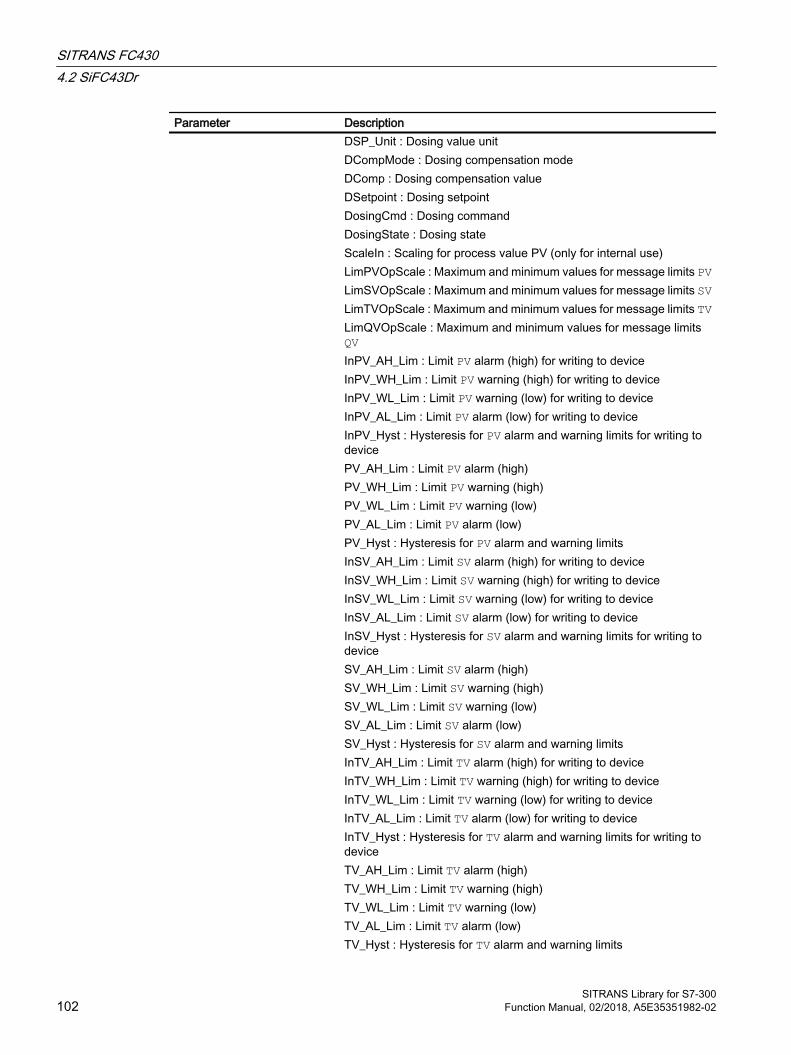
Parameter DescriptionDSP_Unit : Dosing value unitDCompMode : Dosing compensation modeDComp : Dosing compensation value DSetpoint : Dosing setpoint DosingCmd : Dosing commandDosingState : Dosing stateScaleIn : Scaling for process value PV (only for internal use)LimPVOpScale : Maximum and minimum values for message limits PVLimSVOpScale : Maximum and minimum values for message limits SVLimTVOpScale : Maximum and minimum values for message limits TVLimQVOpScale : Maximum and minimum values for message limits QVInPV_AH_Lim : Limit PV alarm (high) for writing to deviceInPV_WH_Lim : Limit PV warning (high) for writing to deviceInPV_WL_Lim : Limit PV warning (low) for writing to deviceInPV_AL_Lim : Limit PV alarm (low) for writing to deviceInPV_Hyst : Hysteresis for PV alarm and warning limits for writing to devicePV_AH_Lim : Limit PV alarm (high) PV_WH_Lim : Limit PV warning (high)PV_WL_Lim : Limit PV warning (low)PV_AL_Lim : Limit PV alarm (low)PV_Hyst : Hysteresis for PV alarm and warning limitsInSV_AH_Lim : Limit SV alarm (high) for writing to deviceInSV_WH_Lim : Limit SV warning (high) for writing to deviceInSV_WL_Lim : Limit SV warning (low) for writing to deviceInSV_AL_Lim : Limit SV alarm (low) for writing to deviceInSV_Hyst : Hysteresis for SV alarm and warning limits for writing to deviceSV_AH_Lim : Limit SV alarm (high) SV_WH_Lim : Limit SV warning (high)SV_WL_Lim : Limit SV warning (low)SV_AL_Lim : Limit SV alarm (low)SV_Hyst : Hysteresis for SV alarm and warning limitsInTV_AH_Lim : Limit TV alarm (high) for writing to deviceInTV_WH_Lim : Limit TV warning (high) for writing to deviceInTV_WL_Lim : Limit TV warning (low) for writing to deviceInTV_AL_Lim : Limit TV alarm (low) for writing to deviceInTV_Hyst : Hysteresis for TV alarm and warning limits for writing to deviceTV_AH_Lim : Limit TV alarm (high) TV_WH_Lim : Limit TV warning (high)TV_WL_Lim : Limit TV warning (low)TV_AL_Lim : Limit TV alarm (low)TV_Hyst : Hysteresis for TV alarm and warning limits
SITRANS FC4304.2 SiFC43Dr
SITRANS Library for S7-300102 Function Manual, 02/2018, A5E35351982-02
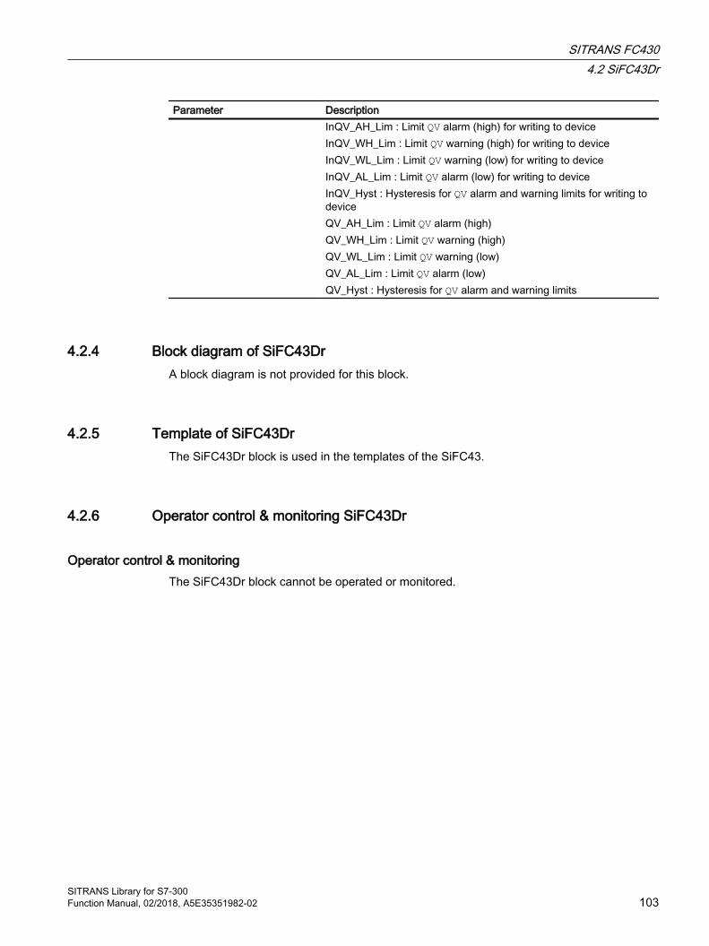
Parameter DescriptionInQV_AH_Lim : Limit QV alarm (high) for writing to deviceInQV_WH_Lim : Limit QV warning (high) for writing to deviceInQV_WL_Lim : Limit QV warning (low) for writing to deviceInQV_AL_Lim : Limit QV alarm (low) for writing to deviceInQV_Hyst : Hysteresis for QV alarm and warning limits for writing to deviceQV_AH_Lim : Limit QV alarm (high) QV_WH_Lim : Limit QV warning (high)QV_WL_Lim : Limit QV warning (low)QV_AL_Lim : Limit QV alarm (low)QV_Hyst : Hysteresis for QV alarm and warning limits
4.2.4 Block diagram of SiFC43DrA block diagram is not provided for this block.
4.2.5 Template of SiFC43DrThe SiFC43Dr block is used in the templates of the SiFC43.
4.2.6 Operator control & monitoring SiFC43Dr
Operator control & monitoringThe SiFC43Dr block cannot be operated or monitored.
SITRANS FC4304.2 SiFC43Dr
SITRANS Library for S7-300Function Manual, 02/2018, A5E35351982-02 103

SITRANS FC4304.2 SiFC43Dr
SITRANS Library for S7-300104 Function Manual, 02/2018, A5E35351982-02
SITRANS LR PA 55.1 S7SiLRPA
5.1.1 Description of S7SiLRPA
Object name (type + number) and family Type + number: FB 2640
Family: Sitrans
Note
The S7SiLRPA block and its faceplate are oriented to the function principle of the PCS 7 APL Library that is not explained in detail in this document. The APL Manual is available for download from the Internet at Siemens Customer Support (http://support.automation.siemens.com/WW/view/de/57265842 (contribution ID:57265842))
Area of application for S7SiLRPA The block is used for the following applications:
● Interface block between the Profibus PA driver blocks of the Sitrans LR 200/250/260/560 module for the user program and for visualization
How it works The S7SiLRPA block prepares the process data received from driver blocks from a Sitrans LR 250 and makes the data available for further use in the user program and for visualization. Data entered in the faceplate or via the block inputs is transferred to the Sitrans LR 250 by means of driver blocks.
The function block supports configuring of the Sitrans LR 250 with one or two inputs.
Configuration Use the CFC editor to install the block in a cyclic interrupt OB (OB30 to OB38). The block is also installed automatically in the startup OB (OB 100). Moreover, to connect the I/O signals it is imperative to call driver block PiDr64 (acyclic data) in the same cyclic interrupt OB and startup OB (OB100) before the S7SiLRPA block is called. The output structure AcyclData of the PiDr64 block is interconnected to the input with the same name of the S7SiLRPA block.
SITRANS Library for S7-300Function Manual, 02/2018, A5E35351982-02 105

The SITRANS Library contains two templates for process tag types as an example with an application scenario for the S7SiLRPA block with one or two analog inputs.
Example of a process tag type: Template of S7SiLRPA (Page 123)
Startup characteristics Use the Feature Bit Setting the startup characteristics (Page 24) to define the startup characteristics of this block.
The messages are suppressed after startup for the number of cycles set at RunUpCyc.
Note
The user text library "S7SiLRPA_MeasVal" must be copied from the Sitrans Library to the STEP 7 project prior to the OS compilation. To do this, open the SITRANS Library from the Simatic Manager using File -> Open... -> Libraries. Copy the "S7SiLRPA_MeasVal" file from the library (directory: Blocks+Templates\Text Libraries) into a user text library folder created using the S7 program in your STEP 7 project.
Status word allocation for Status1 parameter You can find a description for each parameter in section I/Os of S7SiLRPA (Page 116).
Status bit Parameter0 Occupied1 BatchEn2 Not used3 OosAct4 OosLi5 Not used6 OnAct7 - 19 Not used20 Local operator permission (Feature Bit 24)21 - 31 Not Used
Status word allocation for Status2 parameterYou can find a description for each parameter in section I/Os of S7SiLRPA (Page 116).
Status bit Parameter0 MsgLock1 PV1AH_Act2 PV1WH_Act3 PV1WL_Act4 PV1AL_Act
SITRANS LR PA5.1 S7SiLRPA
SITRANS Library for S7-300106 Function Manual, 02/2018, A5E35351982-02

Status bit Parameter5 - 6 Not used7 PV1AH_En8 PV1WH_En9 - 10 Not used11 PV1WL_En12 PV1AL_En13 PV1AH_MsgEn14 PV1WH_MsgEn15 - 16 Not used17 PV1WL_MsgEn18 PV1AL_MsgEn19 GradHUpAct20 GradHDnAct21 GradLAct22 GradHUpEn23 GradHDnEn24 GradLEn25 GradHUpMsgEn26 GradHDnMsgEn27 GradLMsgEn28 0 = decreasing measured value
1 = increasing measured value29 - 31 Not used
Status word allocation for Status3 parameterYou can find a description for each parameter in section I/Os of S7SiLRPA (Page 116).
Status bit Parameter0 - 7 Not used8 PV2AH_Act9 PV2WH_Act10 PV2WL_Act11 PV2AL_Act12 PV2AH_En13 PV2WH_En14 - 15 Not used16 PV2WL_En17 PV2AL_En18 PV2AH_MsgEn19 PV2WH_MsgEn20 - 21 Not used22 PV2WL_MsgEn
SITRANS LR PA5.1 S7SiLRPA
SITRANS Library for S7-300Function Manual, 02/2018, A5E35351982-02 107
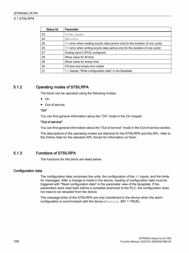
Status bit Parameter23 PV2AL_MsgEn24 QWronDev 25 1 = error when reading acyclic data (active only for the duration of one cycle)26 1 = error when writing acyclic data (active only for the duration of one cycle)27 Analog input 2 (PV2) configured28 Show value for fill time29 Show value for empty time30 Fill time and empty time visible31 1 = display "Write configuration data" in the faceplate
5.1.2 Operating modes of S7SiLRPAThe block can be operated using the following modes:
● On
● Out of service
"On"
You can find general information about the "On" mode in the On chapter.
"Out of service"
You can find general information about the "Out of service" mode in the Out of service section.
The descriptions of the operating modes are identical for the S7SiLRPA and the APL; refer to the Online Help for the standard APL blocks for information on them.
5.1.3 Functions of S7SiLRPAThe functions for this block are listed below.
Configuration data The configuration data comprises the units, the configuration of the PV inputs, and the limits for messages. After a change is made in the device, reading of configuration data must be triggered with "Read configuration data" in the parameter view of the faceplate. If the parameters were read back before a complete download to the PLC, the configuration does not need to be reloaded from the device.
The message limits of the S7SiLRPA are only transferred to the device when the alarm configuration is synchronized with the device (Feature Bit7 = TRUE).
SITRANS LR PA5.1 S7SiLRPA
SITRANS Library for S7-300108 Function Manual, 02/2018, A5E35351982-02
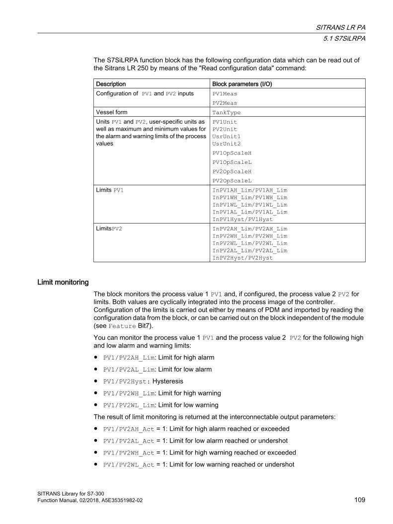
The S7SiLRPA function block has the following configuration data which can be read out of the Sitrans LR 250 by means of the "Read configuration data" command:
Description Block parameters (I/O)Configuration of PV1 and PV2 inputs PV1Meas
PV2MeasVessel form TankTypeUnits PV1 and PV2, user-specific units as well as maximum and minimum values for the alarm and warning limits of the process values
PV1UnitPV2UnitUsrUnit1UsrUnit2PV1OpScaleHPV1OpScaleLPV2OpScaleHPV2OpScaleL
Limits PV1 InPV1AH_Lim/PV1AH_LimInPV1WH_Lim/PV1WH_LimInPV1WL_Lim/PV1WL_LimInPV1AL_Lim/PV1AL_LimInPV1Hyst/PV1Hyst
LimitsPV2 InPV2AH_Lim/PV2AH_LimInPV2WH_Lim/PV2WH_LimInPV2WL_Lim/PV2WL_LimInPV2AL_Lim/PV2AL_LimInPV2Hyst/PV2Hyst
Limit monitoringThe block monitors the process value 1 PV1 and, if configured, the process value 2 PV2 for limits. Both values are cyclically integrated into the process image of the controller. Configuration of the limits is carried out either by means of PDM and imported by reading the configuration data from the block, or can be carried out on the block independent of the module (see Feature Bit7).
You can monitor the process value 1 PV1 and the process value 2 PV2 for the following high and low alarm and warning limits:
● PV1/PV2AH_Lim: Limit for high alarm
● PV1/PV2AL_Lim: Limit for low alarm
● PV1/PV2Hyst: Hysteresis
● PV1/PV2WH_Lim: Limit for high warning
● PV1/PV2WL_Lim: Limit for low warning
The result of limit monitoring is returned at the interconnectable output parameters:
● PV1/PV2AH_Act = 1: Limit for high alarm reached or exceeded
● PV1/PV2AL_Act = 1: Limit for low alarm reached or undershot
● PV1/PV2WH_Act = 1: Limit for high warning reached or exceeded
● PV1/PV2WL_Act = 1: Limit for low warning reached or undershot
SITRANS LR PA5.1 S7SiLRPA
SITRANS Library for S7-300Function Manual, 02/2018, A5E35351982-02 109

Monitoring is always enabled using the input parameters:
● PV1/PV2AH_En = 1: Monitoring of the high alarm limits
● PV1/PV2AL_En = 1: Monitoring of the low alarm limits
● PV1/PV2WH_En = 1: Monitoring of the high warning limits
● PV1/PV2WL_En = 1: Monitoring of the low warning limits
The corresponding message is suppressed using the parameters:
● PV1/PV2AH_MsgEn = 0: Alarm (high) messages are suppressed
● PV1/PV2AL_MsgEn = 0: Alarm (low) messages are suppressed
● PV1/PV2WH_MsgEn = 0: Warning (high) messages are suppressed
● PV1/PV2WL_MsgEn = 0: Warning (low) messages are suppressed
You can define a hysteresis (PV1/PV2Hyst) for the limits, for example to suppress signal flatter. You can also modify the limits and hysteresis via the faceplate.
Gradient monitoringThe gradient PV1Grad is calculated by means of a delay function configurable using LagTime. During calculation of the gradient, jumps in the input value PV1 are smoothed.
The peak values of the gradient are output in the output parameters PV1GradNP (negative gradient) and PV1GradPP (positive gradient). These are reset when the operator enters the corresponding command for resetting.
The slope of the gradient PV1Grad can be monitored for the following limits:
● Limit (high) for the positive gradient (GradHUpLim)
● Limit (high) for the negative gradient (GradHDnLim)
● Limit (low) for the absolute gradient (GradLLim)
Activation of the individual monitoring functions is carried out at the corresponding "Enable" parameters, e.g. GradHUpEn for activating the high gradient limit for positive gradients (GradHUpLim).
Reaching or violation of your defined limits is indicated at the corresponding "Active" output parameters, e.g. by means of GradHUpAct = 1 for the limit (high) for the positive gradient.
Messages can be output for these alarms. You can activate these as follows:
● Message for alarms (high) for the positive gradient: GradHUpMsgEn = 1
● Message for alarms (high) for the negative gradient: GradHDnMsgEn = 1
● Message for alarms (low) for the absolute gradient: GradLMsgEn = 1
Suppressing messages using the MsgLock parameterThis block provides the standard "Suppressing messages using the MsgLock parameter" function that is described in the APL Online Help.
SITRANS LR PA5.1 S7SiLRPA
SITRANS Library for S7-300110 Function Manual, 02/2018, A5E35351982-02

Selecting a unit of measureThe units for process value 1 PV1 and process value 2 PV2 are configured on the device of the Sitrans LR 250 via PDM and read by operator action in the "Parameters" faceplate view with "Read configuration".
Configurable reactions using the Feature I/OThe following response features are available for this block at the respective bits of the Feature connection. If a description is not available here, it can be referenced in the APL Online Help.
Bit Feature0 Setting the startup characteristics1 Reaction to the Out of service mode3 Two decimal places of aux. value in limit messages6 1 = Activate calculation of fill time/empty time7 1 = Message limits are read from the device and transferred to the device in case of a
change9 Reading configuration data automatically
During the start of the controller and when the connection between device and controller is reestablished after an interruption, the configuration data is read automatically by means of acyclic communication.Only 8 acyclic read jobs can be executed simultaneously for each Profibus line. If addi‐tional devices want to read acyclic data simultaneously, the read job is canceled with an error. Alternatively, configuration data can also be read after a change in the device with the click of a button in the faceplate
22 Update acknowledgment and error status of the message call24 Enable local operator authorization25 Suppress all messages26 Reaction of the switching points in "Out of service" mode28 Disabling switching points29 Signaling limit violation
For more information about the feature bits please refer to the APL online help.
Operator authorizationsThis block provides the standard operating permissions that are described in the APL online help.
The block has the following permissions for the OS_Perm parameter:
Bit Function0 Not used1 1 = Operator can switch to "On" mode2 Not used3 1 = Operator can switch to "Out of service" mode4 - 6 Not used
SITRANS LR PA5.1 S7SiLRPA
SITRANS Library for S7-300Function Manual, 02/2018, A5E35351982-02 111
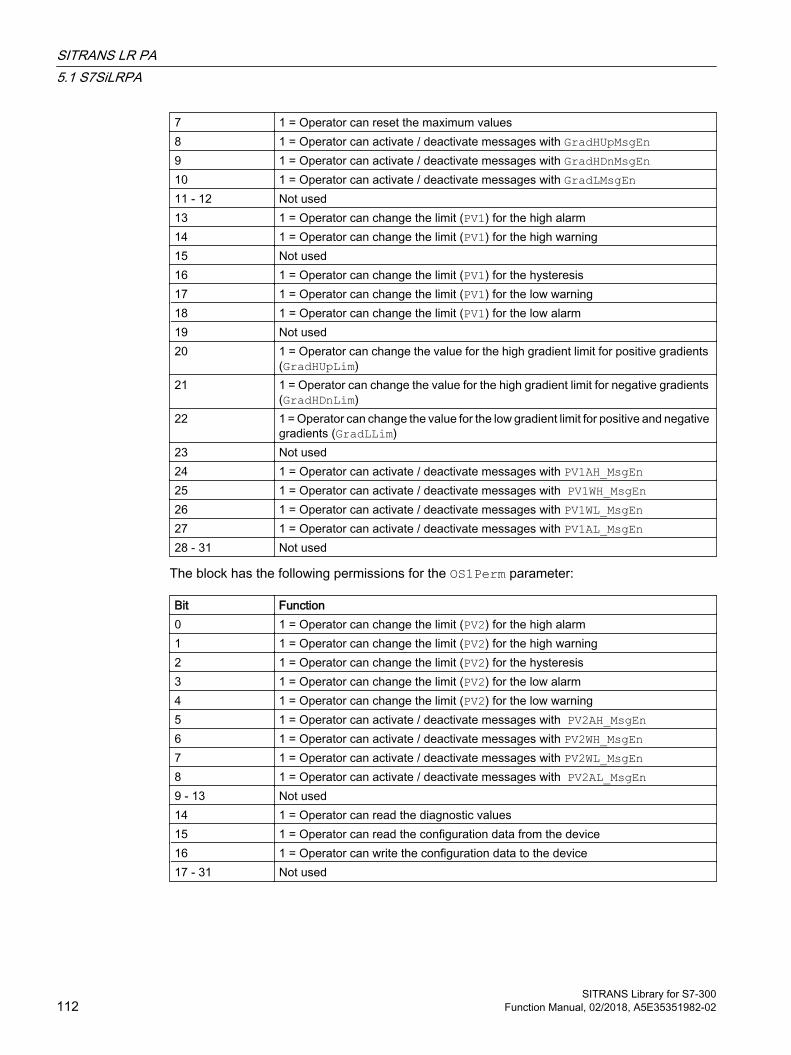
7 1 = Operator can reset the maximum values8 1 = Operator can activate / deactivate messages with GradHUpMsgEn9 1 = Operator can activate / deactivate messages with GradHDnMsgEn10 1 = Operator can activate / deactivate messages with GradLMsgEn11 - 12 Not used13 1 = Operator can change the limit (PV1) for the high alarm14 1 = Operator can change the limit (PV1) for the high warning15 Not used16 1 = Operator can change the limit (PV1) for the hysteresis17 1 = Operator can change the limit (PV1) for the low warning18 1 = Operator can change the limit (PV1) for the low alarm19 Not used20 1 = Operator can change the value for the high gradient limit for positive gradients
(GradHUpLim)21 1 = Operator can change the value for the high gradient limit for negative gradients
(GradHDnLim)22 1 = Operator can change the value for the low gradient limit for positive and negative
gradients (GradLLim)23 Not used24 1 = Operator can activate / deactivate messages with PV1AH_MsgEn25 1 = Operator can activate / deactivate messages with PV1WH_MsgEn26 1 = Operator can activate / deactivate messages with PV1WL_MsgEn27 1 = Operator can activate / deactivate messages with PV1AL_MsgEn28 - 31 Not used
The block has the following permissions for the OS1Perm parameter:
Bit Function0 1 = Operator can change the limit (PV2) for the high alarm1 1 = Operator can change the limit (PV2) for the high warning2 1 = Operator can change the limit (PV2) for the hysteresis3 1 = Operator can change the limit (PV2) for the low alarm4 1 = Operator can change the limit (PV2) for the low warning5 1 = Operator can activate / deactivate messages with PV2AH_MsgEn6 1 = Operator can activate / deactivate messages with PV2WH_MsgEn7 1 = Operator can activate / deactivate messages with PV2WL_MsgEn8 1 = Operator can activate / deactivate messages with PV2AL_MsgEn9 - 13 Not used14 1 = Operator can read the diagnostic values15 1 = Operator can read the configuration data from the device16 1 = Operator can write the configuration data to the device17 - 31 Not used
SITRANS LR PA5.1 S7SiLRPA
SITRANS Library for S7-300112 Function Manual, 02/2018, A5E35351982-02

Display and operating range for process values and limitsThe scalings from the Sitrans LR 250 are read out as the display and operating range (PV1OpScaleH/L, PV2OpScaleH/L) for the process values PV1 and PV2.
Generating instance-specific messagesThis block provides the standard "Generate instance-specific messages" function that is described in the APL Online Help.
SIMATIC BATCH functionalityThis block provides the standard "SIMATIC BATCH functionality" function that is described in the APL Online Help.
5.1.4 Error handling of S7SiLRPAFor general information on error handling at all blocks, refer to the "Error handling" section in the APL Online Help.
The following errors can be displayed for this block:
● Error numbers
● Control system fault (CSF)
Control system fault (CSF)An external signal can be activated via the CSF input. A process control error is triggered if this signal = 1. Refer to the "Error handling" chapter in the APL Online Help.
5.1.5 S7SiLRPA messaging
Messaging The following messages can be generated for this block:
● Process control error
● Process messages
● Instance-specific messages
SITRANS LR PA5.1 S7SiLRPA
SITRANS Library for S7-300Function Manual, 02/2018, A5E35351982-02 113

Process control errors The following control system fault messages can be output:
Message in‐stance
Message class Event
MsgEvId12
AS process control message - fault
External error has occurred (S7SiLRPA: #@3X%3u@) [BatchID:@2X%3u@] [Auxiliary value:@1R%4.1f@]
MsgEvId13 AS process control message - error
Error while reading a data record (S7SiLRPA: #@3X%3u@) [BatchID:@2X%3u@] [Auxiliary value:@1R%4.1f@]
MsgEvId14 AS process control message - error
Error while writing a data record (S7SiLRPA: #@3X%3u@) [BatchID:@2X%3u@] [Auxiliary value:@1R%4.1f@]
You can interconnect an external fault (signal) to the input parameter CSF. If this signal changes to CSF = 1, a process control error is triggered (MsgEvId12).
Process messages
Message in‐stance
Message class Event
MsgEvId01 Alarm - high @1Y%t#S7SiLRPA_MeasVal@ - High alarm limit violated (S7SiLRPA: #@3X%3u@) [BatchID:@2X%3u@] [Auxiliary value:@2I%d@.@2Y%1u@]
MsgEvId02 Warning - high @1Y%t#S7SiLRPA_MeasVal@ - High warning limit violated (S7SiLRPA: #@3X%3u@) [BatchID:@2X%3u@] [Auxiliary value:@2I%d@.@2Y%1u@]
MsgEvId03 Warning - low @1Y%t#S7SiLRPA_MeasVal@ - Low warning limit violated (S7SiLRPA: #@3X%3u@) [BatchID:@2X%3u@] [Auxiliary value:@2I%d@.@2Y%1u@]
MsgEvId04 Alarm - low @1Y%t#S7SiLRPA_MeasVal@ - Low alarm limit violated (S7SiLRPA: #@3X%3u@) [BatchID:@2X%3u@] [Auxiliary value:@2I%d@.@2Y%1u@]
MsgEvId05 Alarm - high @1Y%t#S7SiLRPA_MeasVal@ - High alarm limit violated (S7SiLRPA: #@3X%3u@) [BatchID:@2X%3u@] [Auxiliary value:@2I%d@.@2Y%1u@]
MsgEvId06 Warning - high @1Y%t#S7SiLRPA_MeasVal@ - High warning limit violated (S7SiLRPA: #@3X%3u@) [BatchID:@2X%3u@] [Auxiliary value:@2I%d@.@2Y%1u@]
MsgEvId07 Warning - low @1Y%t#S7SiLRPA_MeasVal@ - Low warning limit violated (S7SiLRPA: #@3X%3u@) [BatchID:@2X%3u@] [Auxiliary value:@2I%d@.@2Y%1u@]
MsgEvId08 Alarm - low @1Y%t#S7SiLRPA_MeasVal@ - Low alarm limit violated (S7SiLRPA: #@3X%3u@) [BatchID:@2X%3u@] [Auxiliary value:@2I%d@.@2Y%1u@]
MsgEvId09 Alarm - high Limit value (high) for the positive gradient violated (S7SiLR‐PA: #@3X%3u@) [BatchID:@2X%3u@] [Auxiliary val‐ue:@1R%4.1f@]
SITRANS LR PA5.1 S7SiLRPA
SITRANS Library for S7-300114 Function Manual, 02/2018, A5E35351982-02

MsgEvId10 Alarm - high Limit value (high) for the negative gradient violated (S7SiLR‐PA: #@3X%3u@) [BatchID:@2X%3u@] [Auxiliary val‐ue:@1R%4.1f@]
MsgEvId11 Alarm - low Limit value (low) for absolute gradient violated (S7SiLRPA: #@3X%3u@) [BatchID:@2X%3u@] [Auxiliary value:@1R%4.1f@]
The content of the message text library "S7SiLRPA_MeasVal" is described below.
Instance-specific message You can use one instance-specific message with this block.
Message in‐stance
Message class Event
MsgEvId15 AS process control message - fault
External message (S7SiLRPA: #@3X%3u@) [Batch‐ID:@2X%3u@] [Auxiliary value:@1R%4.1f@]
Associated values for message instances with limit violation
Associated value Block parameter Data Type1 PV_Meas0 BYTE2 AuxByte (one or two digits after
the decimal point, see Fea‐ture.Bit3)
BYTE
3 AuxWord (number before the decimal point: -32768 .. 32767)
WORD
4 BatchID DWORD5 MsgFilter DINT
Associated values for message instances without limit violation
Associated value Block parameter Data Type1 Aux REAL2 BatchID DWORD3 MsgFilter DINT
Message texts and their text numbers The following table shows the message texts and their numbers in the text library "S7SiLRPA_MeasVal" for the S7SiLRPA block (FB 2640):
Text number Message text0 <Invalid value>1 Volume2 Level3 Distance
SITRANS LR PA5.1 S7SiLRPA
SITRANS Library for S7-300Function Manual, 02/2018, A5E35351982-02 115
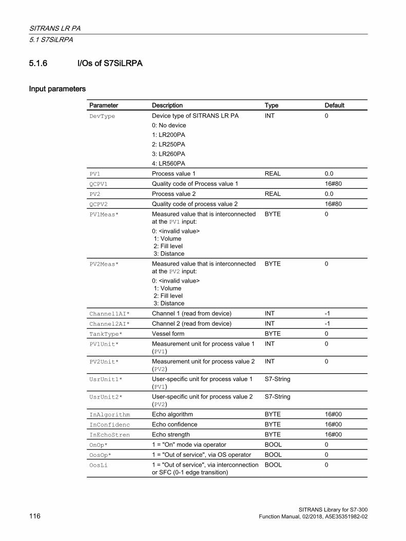
5.1.6 I/Os of S7SiLRPA
Input parameters
Parameter Description Type DefaultDevType Device type of SITRANS LR PA
0: No device1: LR200PA2: LR250PA3: LR260PA4: LR560PA
INT 0
PV1 Process value 1 REAL 0.0QCPV1 Quality code of Process value 1 16#80PV2 Process value 2 REAL 0.0QCPV2 Quality code of process value 2 16#80PV1Meas* Measured value that is interconnected
at the PV1 input:0: <invalid value> 1: Volume 2: Fill level 3: Distance
BYTE 0
PV2Meas* Measured value that is interconnected at the PV2 input:0: <invalid value> 1: Volume 2: Fill level 3: Distance
BYTE 0
Channel1AI* Channel 1 (read from device) INT -1Channel2AI* Channel 2 (read from device) INT -1TankType* Vessel form BYTE 0PV1Unit* Measurement unit for process value 1
(PV1)INT 0
PV2Unit* Measurement unit for process value 2 (PV2)
INT 0
UsrUnit1* User-specific unit for process value 1 (PV1)
S7-String
UsrUnit2* User-specific unit for process value 2 (PV2)
S7-String
InAlgorithm Echo algorithm BYTE 16#00InConfidenc Echo confidence BYTE 16#00InEchoStren Echo strength BYTE 16#00OnOp* 1 = "On" mode via operator BOOL 0OosOp* 1 = "Out of service", via OS operator BOOL 0OosLi 1 = "Out of service", via interconnection
or SFC (0-1 edge transition)BOOL 0
SITRANS LR PA5.1 S7SiLRPA
SITRANS Library for S7-300116 Function Manual, 02/2018, A5E35351982-02
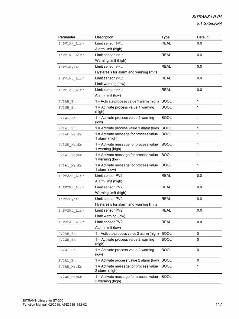
Parameter Description Type DefaultInPV1AH_Lim* Limit sensor PV1:
Alarm limit (high) REAL 0.0
InPV1WH_Lim* Limit sensor PV1:Warning limit (high)
REAL 0.0
InPV1Hyst* Limit sensor PV1:Hysteresis for alarm and warning limits
REAL 0.0
InPV1WL_Lim* Limit sensor PV1:Limit warning (low)
REAL 0.0
InPV1AL_Lim* Limit sensor PV1:Alarm limit (low)
REAL 0.0
PV1AH_En 1 = Activate process value 1 alarm (high) BOOL 1PV1WH_En 1 = Activate process value 1 warning
(high)BOOL 1
PV1WL_En 1 = Activate process value 1 warning (low)
BOOL 1
PV1AL_En 1 = Activate process value 1 alarm (low) BOOL 1PV1AH_MsgEn 1 = Activate message for process value
1 alarm (high)BOOL 1
PV1WH_MsgEn 1 = Activate message for process value 1 warning (high)
BOOL 1
PV1WL_MsgEn 1 = Activate message for process value 1 warning (low)
BOOL 1
PV1AL_MsgEn 1 = Activate message for process value 1 alarm (low)
BOOL 1
InPV2AH_Lim* Limit sensor PV2:Alarm limit (high)
REAL 0.0
InPV2WH_Lim* Limit sensor PV2:Warning limit (high)
REAL 0.0
InPV2Hyst* Limit sensor PV2:Hysteresis for alarm and warning limits
REAL 0.0
InPV2WL_Lim* Limit sensor PV2:Limit warning (low)
REAL 0.0
InPV2AL_Lim* Limit sensor PV2:Alarm limit (low)
REAL 0.0
PV2AH_En 1 = Activate process value 2 alarm (high) BOOL 0PV2WH_En 1 = Activate process value 2 warning
(high)BOOL 0
PV2WL_En 1 = Activate process value 2 warning (low)
BOOL 0
PV2AL_En 1 = Activate process value 2 alarm (low) BOOL 0PV2AH_MsgEn 1 = Activate message for process value
2 alarm (high)BOOL 1
PV2WH_MsgEn 1 = Activate message for process value 2 warning (high)
BOOL 1
SITRANS LR PA5.1 S7SiLRPA
SITRANS Library for S7-300Function Manual, 02/2018, A5E35351982-02 117
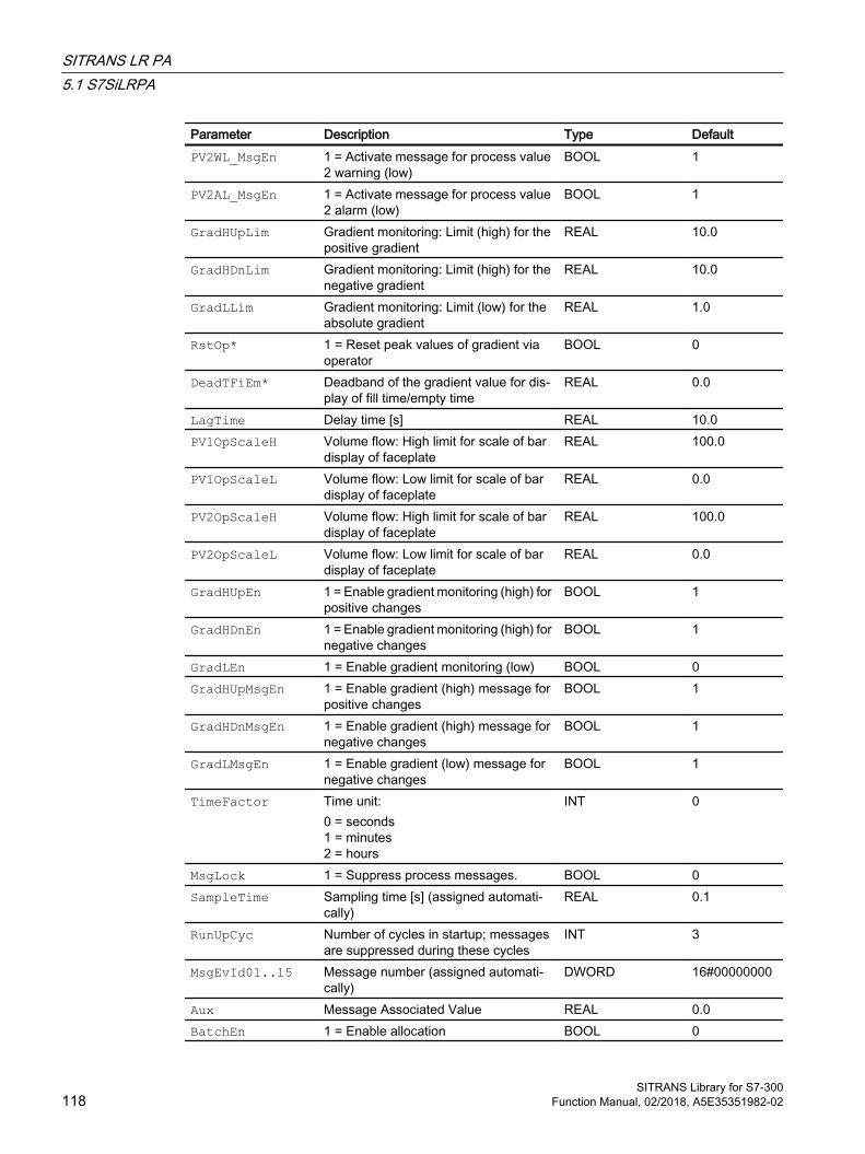
Parameter Description Type DefaultPV2WL_MsgEn 1 = Activate message for process value
2 warning (low)BOOL 1
PV2AL_MsgEn 1 = Activate message for process value 2 alarm (low)
BOOL 1
GradHUpLim Gradient monitoring: Limit (high) for the positive gradient
REAL 10.0
GradHDnLim Gradient monitoring: Limit (high) for the negative gradient
REAL 10.0
GradLLim Gradient monitoring: Limit (low) for the absolute gradient
REAL 1.0
RstOp* 1 = Reset peak values of gradient via operator
BOOL 0
DeadTFiEm* Deadband of the gradient value for dis‐play of fill time/empty time
REAL 0.0
LagTime Delay time [s] REAL 10.0PV1OpScaleH Volume flow: High limit for scale of bar
display of faceplateREAL 100.0
PV1OpScaleL Volume flow: Low limit for scale of bar display of faceplate
REAL 0.0
PV2OpScaleH Volume flow: High limit for scale of bar display of faceplate
REAL 100.0
PV2OpScaleL Volume flow: Low limit for scale of bar display of faceplate
REAL 0.0
GradHUpEn 1 = Enable gradient monitoring (high) for positive changes
BOOL 1
GradHDnEn 1 = Enable gradient monitoring (high) for negative changes
BOOL 1
GradLEn 1 = Enable gradient monitoring (low) BOOL 0GradHUpMsgEn 1 = Enable gradient (high) message for
positive changesBOOL 1
GradHDnMsgEn 1 = Enable gradient (high) message for negative changes
BOOL 1
GradLMsgEn 1 = Enable gradient (low) message for negative changes
BOOL 1
TimeFactor Time unit:0 = seconds1 = minutes2 = hours
INT 0
MsgLock 1 = Suppress process messages. BOOL 0SampleTime Sampling time [s] (assigned automati‐
cally)REAL 0.1
RunUpCyc Number of cycles in startup; messages are suppressed during these cycles
INT 3
MsgEvId01..15 Message number (assigned automati‐cally)
DWORD 16#00000000
Aux Message Associated Value REAL 0.0BatchEn 1 = Enable allocation BOOL 0
SITRANS LR PA5.1 S7SiLRPA
SITRANS Library for S7-300118 Function Manual, 02/2018, A5E35351982-02

Parameter Description Type DefaultBatchID Batch ID DWORD 16#00000000BatchName Batch name S7-String StepNo Batch step number DWORD 16#00000000Occupied 1 = Occupied by batch control BOOL 0MsgFilter Message Filter DINT 0CmpID component identifier (not permissible: 0)
Identification of the subsystem to which the message is assigned to Recommen‐ded values: ● low word: 1 to 65535● high word: 0
DWORD 16#00000001
PERMIS Switchover of the operator control per‐mission
INT 2
CSF 1 = External error (control system fault) BOOL 0ExtMsg Binary input for freely selectable mes‐
sageBOOL 0
UserStatus Freely assignable bits for use in PCS 7 OS
BYTE 16#00
OS_Perm I/O for operating permissions STRUCT● Bit 0 : BOOL…● Bit31: BOOL
-● 1…● 1
OS1Perm I/O for operating permissions STRUCT● Bit 0 : BOOL…● Bit31: BOOL
-● 1…● 1
Feature I/O for additional functions STRUCT● Bit 0 : BOOL● Bit 1 : BOOL● Bit 2 : BOOL…● Bit 6 : BOOL● Bit 7 : BOOL …● Bit31: BOOL
-● 0● 0● 1 ● 1● 0 ● 0
MaxVol Range of volume High Value (only for read back)
REAL
0.0
MinVol Range of volume Low Value (only for read back)
REAL
0.0
CalInH High range of calibration setpoints (only for read back)
REAL
0.0
CalInL Low range of calibration setpoints (only for read back)
REAL
0.0
SITRANS LR PA5.1 S7SiLRPA
SITRANS Library for S7-300Function Manual, 02/2018, A5E35351982-02 119

Parameter Description Type DefaultRdCfgOp* 1 = Read all configuration data from the
Sitrans LR 250BOOL 0
WrCfgOp* 1 = Write all configuration data to the Si‐trans LR 250
BOOL 0
* Values can be written back to these inputs during processing of the block by the block algorithm.
In/out parameters
Parameter Description Type DefaultAcyclData Acyclic data from driver block PiDr64 (intercon‐
nect this input with AcyclData output of PiDr64)
STRUCT● SlotRd : INT● …● RetValWr: WORD● Input : STRUCT● Output : STRUCT● NewDiag : INT● DiagData : STRUCT
Output parameters
Parameter Description Type DefaultQWronDev 1 = Wrong device connected BOOL 1PV1Out Output for process value PV1 REAL 0.0QCPV1Out State of current Process value 1 BYTE 16#80PV2Out Output for process value PV2 REAL 0.0QCPV2Out State of current Process value 2 BYTE 16#80TankFilled Output for process value PV1 in [%] REAL 0.0TimeFillS Fill time calculated with current gradient value [s] REAL 0.0TimeEmptyS Empty time calculated with current gradient value
[s]REAL 0.0
TimeFill Fill time calculated with current gradient value [s] REAL 0.0TimeEmpty Empty time calculated with current gradient value
[TEmptyUnit]REAL 0.0
TFillUnit Unit of TimeFill INT 0TEmptyUnit Unit of TimeEmpty INT A0Algorithm Echo algorithm BYTE 16#00Confidenc Echo confidence BYTE 16#00EchoStren Echo strength BYTE 16#00PV1Grad Gradient value for process value PV1 REAL 0.0PV1GradPP Gradient value for PV1, max. peak value REAL 0.0PV1GradNP Gradient value for PV1, min. peak value REAL 0.0
SITRANS LR PA5.1 S7SiLRPA
SITRANS Library for S7-300120 Function Manual, 02/2018, A5E35351982-02

Parameter Description Type DefaultPV1AH_Act Limit sensor PV1:
1 = Alarm (high) active. You can change the response for this parameter by setting Feature bit 28 (deactivate switching points) and Feature bit 29 (high/low signal limit vi‐olation) accordingly.
BOOL 0
PV1WH_Act Limit sensor PV1:1 = Warning (high) active. You can change the response for this parameter by setting Feature bit 28 (deactivate switching points) and Feature bit 29 (signal limit violation) ac‐cordingly.
BOOL 0
PV1WL_Act Limit sensor PV1:1 = Warning (low) active. You can change the response for this parameter by setting Feature bit 28 (deactivate switching points) and Feature bit 29 (signal limit violation) ac‐cordingly.
BOOL 0
PV1AL_Act Limit sensor PV1:1 = Alarm (low) active. You can change the response for this parameter by setting Feature bit 28 (deactivate switching points) and Feature bit 29 (signal limit violation) ac‐cordingly.
BOOL 0
PV2AH_Act Limit sensor PV2:1 = Alarm (high) active. You can change the response for this parameter by setting Feature bit 28 (deactivate switching points) and Feature bit 29 (high/low signal limit vi‐olation) accordingly.
BOOL 0
PV2WH_Act Limit sensor PV2:1 = Warning (high) active. You can change the response for this parameter by setting Feature bit 28 (deactivate switching points) and Feature bit 29 (signal limit violation) ac‐cordingly.
BOOL 0
PV2WL_Act Limit sensor PV2:1 = Warning (low) active. You can change the response for this parameter by setting Feature bit 28 (deactivate switching points) and Feature bit 29 (signal limit violation) ac‐cordingly.
BOOL 0
PV2AL_Act Limit sensor PV2:1 = Alarm (low) active. You can change the response for this parameter by setting Feature bit 28 (deactivate switching points) and Feature bit 29 (signal limit violation) ac‐cordingly.
BOOL 0
SumMsgAct 1 = Group signal is active BOOL 0
SITRANS LR PA5.1 S7SiLRPA
SITRANS Library for S7-300Function Manual, 02/2018, A5E35351982-02 121
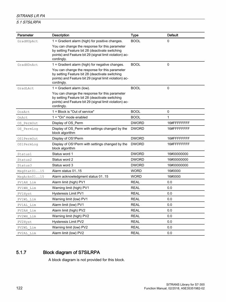
Parameter Description Type DefaultGradHUpAct 1 = Gradient alarm (high) for positive changes.
You can change the response for this parameter by setting Feature bit 28 (deactivate switching points) and Feature bit 29 (signal limit violation) ac‐cordingly.
BOOL 0
GradHDnAct 1 = Gradient alarm (high) for negative changes. You can change the response for this parameter by setting Feature bit 28 (deactivate switching points) and Feature bit 29 (signal limit violation) ac‐cordingly.
BOOL 0
GradLAct 1 = Gradient alarm (low).You can change the response for this parameter by setting Feature bit 28 (deactivate switching points) and Feature bit 29 (signal limit violation) ac‐cordingly.
BOOL 0
OosAct 1 = Block is "Out of service" BOOL 0OnAct 1 = "On" mode enabled BOOL 1OS_PermOut Display of OS_Perm DWORD 16#FFFFFFFFOS_PermLog Display of OS_Perm with settings changed by the
block algorithmDWORD 16#FFFFFFFF
OS1PermOut Display of OS1Perm DWORD 16#FFFFFFFFOS1PermLog Display of OS1Perm with settings changed by the
block algorithmDWORD 16#FFFFFFFF
Status1 Status word 1 DWORD 16#00000000Status2 Status word 2 DWORD 16#00000000Status3 Status word 3 DWORD 16#00000000MsgStat01..15 Alarm status 01..15 WORD 16#0000MsgAckn01..15 Alarm acknowledgment status 01..15 WORD 16#0000PV1AH_Lim Alarm limit (high) PV1 REAL 0.0PV1WH_Lim Warning limit (high) PV1 REAL 0.0PV1Hyst Hysteresis Limit PV1 REAL 0.0PV1WL_Lim Warning limit (low) PV1 REAL 0.0PV1AL_Lim Alarm limit (low) PV1 REAL 0.0PV2AH_Lim Alarm limit (high) PV2 REAL 0.0PV2WH_Lim Warning limit (high) PV2 REAL 0.0PV2Hyst Hysteresis Limit PV2 REAL 0.0PV2WL_Lim Warning limit (low) PV2 REAL 0.0PV2AL_Lim Alarm limit (low) PV2 REAL 0.0
5.1.7 Block diagram of S7SiLRPAA block diagram is not provided for this block.
SITRANS LR PA5.1 S7SiLRPA
SITRANS Library for S7-300122 Function Manual, 02/2018, A5E35351982-02
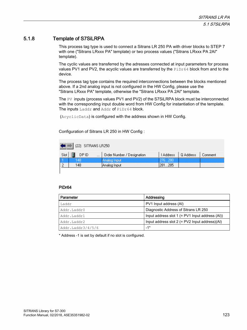
5.1.8 Template of S7SiLRPAThis process tag type is used to connect a Sitrans LR 250 PA with driver blocks to STEP 7 with one ("Sitrans LRxxx PA" template) or two process values ("Sitrans LRxxx PA 2AI" template).
The cyclic values are transferred by the adresses connected at input parameters for process values PV1 and PV2, the acyclic values are transferred by the PiDr64 block from and to the device.
The process tag type contains the required interconnections between the blocks mentioned above. If a 2nd analog input is not configured in the HW Config, please use the "Sitrans LRxxx PA" template, otherwise the "Sitrans LRxxx PA 2AI" template.
The PV inputs (process values PV1 and PV2) of the S7SiLRPA block must be interconnected with the corresponding input double word from HW Config for instantiation of the template. The inputs Laddr and Addr of PiDr64 block.
(AcyclicData) is configured with the address shown in HW Config.
Configuration of Sitrans LR 250 in HW Config :
PiDr64
Parameter AddressingLaddr PV1 Input address (AI)Addr.Laddr0 Diagnostic Address of Sitrans LR 250Addr.Laddr1 Input address slot 1 (= PV1 Input address (AI))Addr.Laddr2 Input address slot 2 (= PV2 Input address)(AI)Addr.Laddr3/4/5/6 -1*
* Address -1 is set by default if no slot is configured.
SITRANS LR PA5.1 S7SiLRPA
SITRANS Library for S7-300Function Manual, 02/2018, A5E35351982-02 123

5.1.9 Operator control & monitoring
5.1.9.1 Views of S7SiLRPA
Views of the SiLRPA blockThe SitrLRPA block has the following views:
● Standard view of S7SiLRPA (Page 125)
● Message view (see the APL online help)
● Limit view of S7SiLRPA (Page 128)
● Trend view (see the APL online help)
● Parameter view of S7SiLRPA (Page 130)
● Preview of S7SiLRPA (Page 131)
● Batch view (see the APL online help)
For general information on the faceplate and block icon, refer to the sections "Faceplate structure" and "Block icon structure" in the APL Online Help
SITRANS LR PA5.1 S7SiLRPA
SITRANS Library for S7-300124 Function Manual, 02/2018, A5E35351982-02
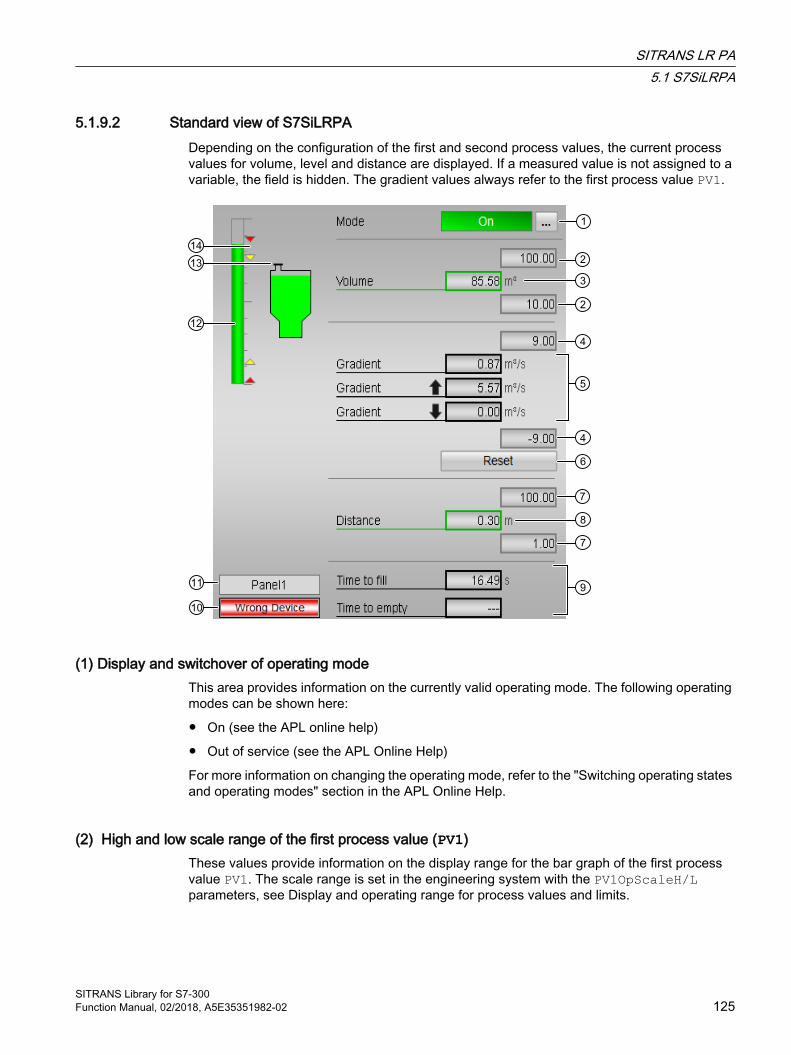
5.1.9.2 Standard view of S7SiLRPADepending on the configuration of the first and second process values, the current process values for volume, level and distance are displayed. If a measured value is not assigned to a variable, the field is hidden. The gradient values always refer to the first process value PV1.
(1) Display and switchover of operating modeThis area provides information on the currently valid operating mode. The following operating modes can be shown here:
● On (see the APL online help)
● Out of service (see the APL Online Help)
For more information on changing the operating mode, refer to the "Switching operating states and operating modes" section in the APL Online Help.
(2) High and low scale range of the first process value (PV1)These values provide information on the display range for the bar graph of the first process value PV1. The scale range is set in the engineering system with the PV1OpScaleH/L parameters, see Display and operating range for process values and limits.
SITRANS LR PA5.1 S7SiLRPA
SITRANS Library for S7-300Function Manual, 02/2018, A5E35351982-02 125
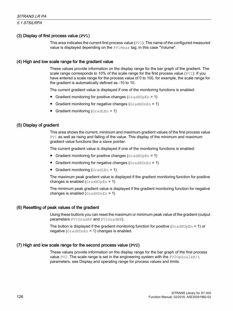
(3) Display of first process value (PV1)This area indicates the current first process value (PV1). The name of the configured measured value is displayed depending on the PV1Meas tag, in this case "Volume".
(4) High and low scale range for the gradient valueThese values provide information on the display range for the bar graph of the gradient. The scale range corresponds to 10% of the scale range for the first process value (PV1): If you have entered a scale range for the process value of 0 to 100, for example, the scale range for the gradient is automatically defined as -10 to 10.
The current gradient value is displayed if one of the monitoring functions is enabled:
● Gradient monitoring for positive changes (GradHUpEn = 1)
● Gradient monitoring for negative changes (GradHDnEn = 1)
● Gradient monitoring (GradLEn = 1)
(5) Display of gradientThis area shows the current, minimum and maximum gradient values of the first process value PV1 as well as rising and falling of the value. This display of the minimum and maximum gradient value functions like a slave pointer.
The current gradient value is displayed if one of the monitoring functions is enabled:
● Gradient monitoring for positive changes (GradHUpEn = 1)
● Gradient monitoring for negative changes (GradHDnEn = 1)
● Gradient monitoring (GradLEn = 1)
The maximum peak gradient value is displayed if the gradient monitoring function for positive changes is enabled (GradHUpEn = 1)
The minimum peak gradient value is displayed if the gradient monitoring function for negative changes is enabled (GradHDnEn = 1)
(6) Resetting of peak values of the gradientUsing these buttons you can reset the maximum or minimum peak value of the gradient (output parameters PV1GradPP and PV1GradNP).
The button is displayed if the gradient monitoring function for positive (GradHUpEn = 1) or negative (GradHDnEn = 1) changes is enabled.
(7) High and low scale range for the second process value (PV2)These values provide information on the display range for the bar graph of the first process value PV2. The scale range is set in the engineering system with the PV2OpScaleH/L parameters, see Display and operating range for process values and limits.
SITRANS LR PA5.1 S7SiLRPA
SITRANS Library for S7-300126 Function Manual, 02/2018, A5E35351982-02
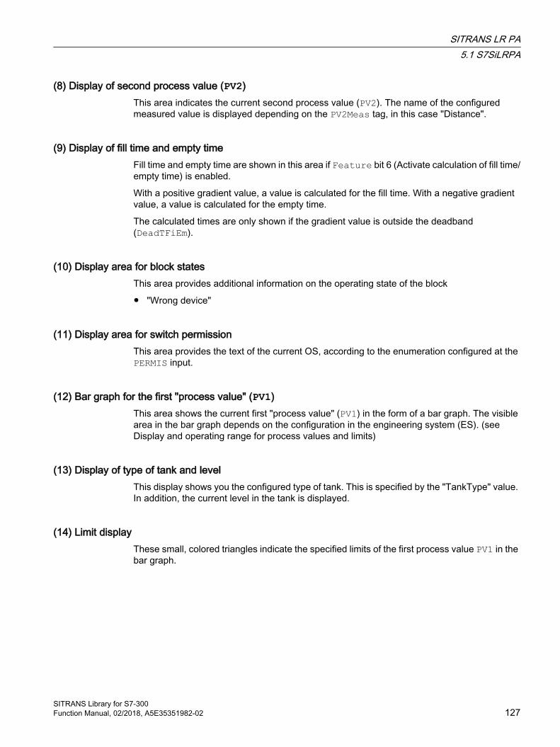
(8) Display of second process value (PV2)This area indicates the current second process value (PV2). The name of the configured measured value is displayed depending on the PV2Meas tag, in this case "Distance".
(9) Display of fill time and empty timeFill time and empty time are shown in this area if Feature bit 6 (Activate calculation of fill time/empty time) is enabled.
With a positive gradient value, a value is calculated for the fill time. With a negative gradient value, a value is calculated for the empty time.
The calculated times are only shown if the gradient value is outside the deadband (DeadTFiEm).
(10) Display area for block statesThis area provides additional information on the operating state of the block
● "Wrong device"
(11) Display area for switch permissionThis area provides the text of the current OS, according to the enumeration configured at the PERMIS input.
(12) Bar graph for the first "process value" (PV1)This area shows the current first "process value" (PV1) in the form of a bar graph. The visible area in the bar graph depends on the configuration in the engineering system (ES). (see Display and operating range for process values and limits)
(13) Display of type of tank and levelThis display shows you the configured type of tank. This is specified by the "TankType" value. In addition, the current level in the tank is displayed.
(14) Limit displayThese small, colored triangles indicate the specified limits of the first process value PV1 in the bar graph.
SITRANS LR PA5.1 S7SiLRPA
SITRANS Library for S7-300Function Manual, 02/2018, A5E35351982-02 127

5.1.9.3 Limit view of S7SiLRPAThe limits of the first process value PV1 and the second process value PV2 can be specified in this view. The displayed texts depend on the configuration of the process values PV1 and PV2.
(1) Process value limits (PV1)In this area, you can enter the limits for the first process value PV1. You can change the following limits:
● "H alarm": High alarm
● "H warning": High warning
● "Hysteresis"
● "L warning": Low warning
● "L alarm": Low alarm
SITRANS LR PA5.1 S7SiLRPA
SITRANS Library for S7-300128 Function Manual, 02/2018, A5E35351982-02

Note
If the Feature bit 7 (synchronize alarm configuration with module) is set, the measuring range limits available in the module are written to the corresponding inputs when reading the configuration data.
(2) Process value limits (PV2)In this area, you can enter the limits for the second process value PV2. You can change the following limits:
● "H alarm": High alarm
● "H warning": High warning
● "Hysteresis"
● "L warning": Low warning
● "L alarm": Low alarm
Note
If the Feature bit 7 (synchronize alarm configuration with module) is set, the measuring range limits available in the module are written to the corresponding inputs when reading the configuration data.
(3) Gradient limits You can enter gradient limits in this area. Refer to the "Changing values" section in the APL online Help.
You can change the following limits:
● "H alarm ⇑": Gradient for the upper gradient for positive changes
● "H alarm ⇓": Gradient for the upper rate of rise for negative changes
● "L alarm ⇑⇓": Gradient for the lower rate of rise (absolute)
(4) Suppress messagesYou can activate/deactivate messages by selecting the check mark.
(5) Enabled operationsThis area shows all operations for which special operator authorizations are assigned. They depend on the configuration in the engineering system (ES) that applies to this block.
SITRANS LR PA5.1 S7SiLRPA
SITRANS Library for S7-300Function Manual, 02/2018, A5E35351982-02 129
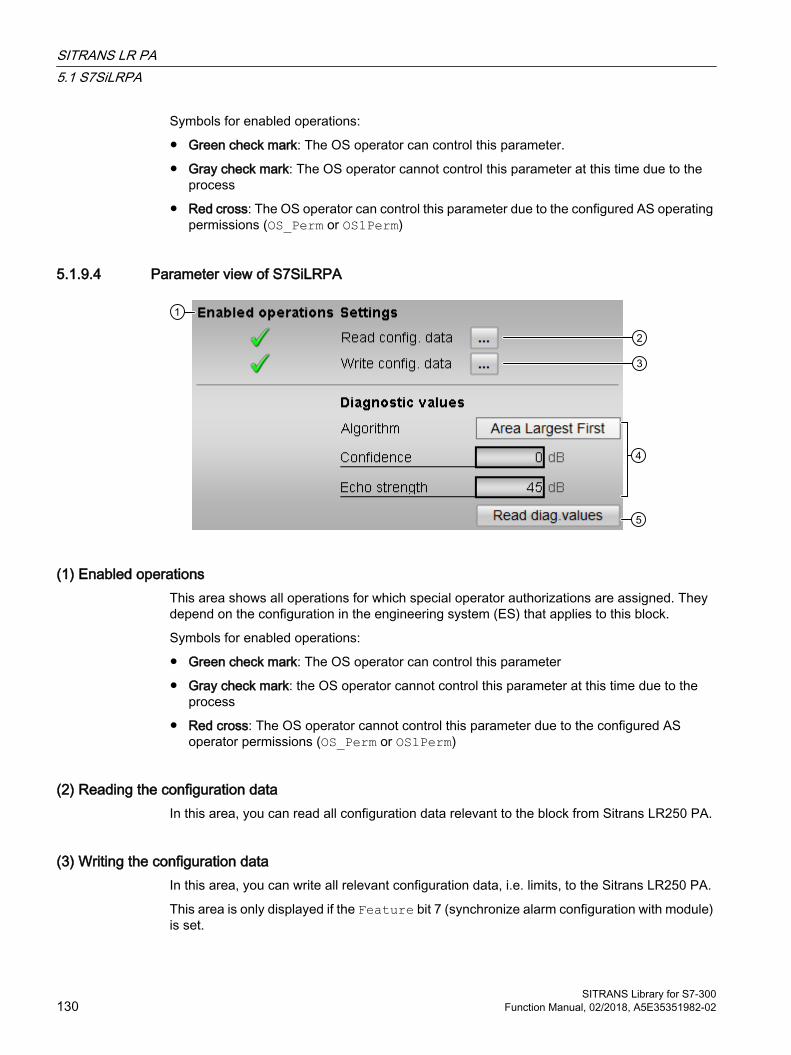
Symbols for enabled operations:
● Green check mark: The OS operator can control this parameter.
● Gray check mark: The OS operator cannot control this parameter at this time due to the process
● Red cross: The OS operator can control this parameter due to the configured AS operating permissions (OS_Perm or OS1Perm)
5.1.9.4 Parameter view of S7SiLRPA
(1) Enabled operationsThis area shows all operations for which special operator authorizations are assigned. They depend on the configuration in the engineering system (ES) that applies to this block.
Symbols for enabled operations:
● Green check mark: The OS operator can control this parameter
● Gray check mark: the OS operator cannot control this parameter at this time due to the process
● Red cross: The OS operator cannot control this parameter due to the configured AS operator permissions (OS_Perm or OS1Perm)
(2) Reading the configuration dataIn this area, you can read all configuration data relevant to the block from Sitrans LR250 PA.
(3) Writing the configuration dataIn this area, you can write all relevant configuration data, i.e. limits, to the Sitrans LR250 PA.
This area is only displayed if the Feature bit 7 (synchronize alarm configuration with module) is set.
SITRANS LR PA5.1 S7SiLRPA
SITRANS Library for S7-300130 Function Manual, 02/2018, A5E35351982-02
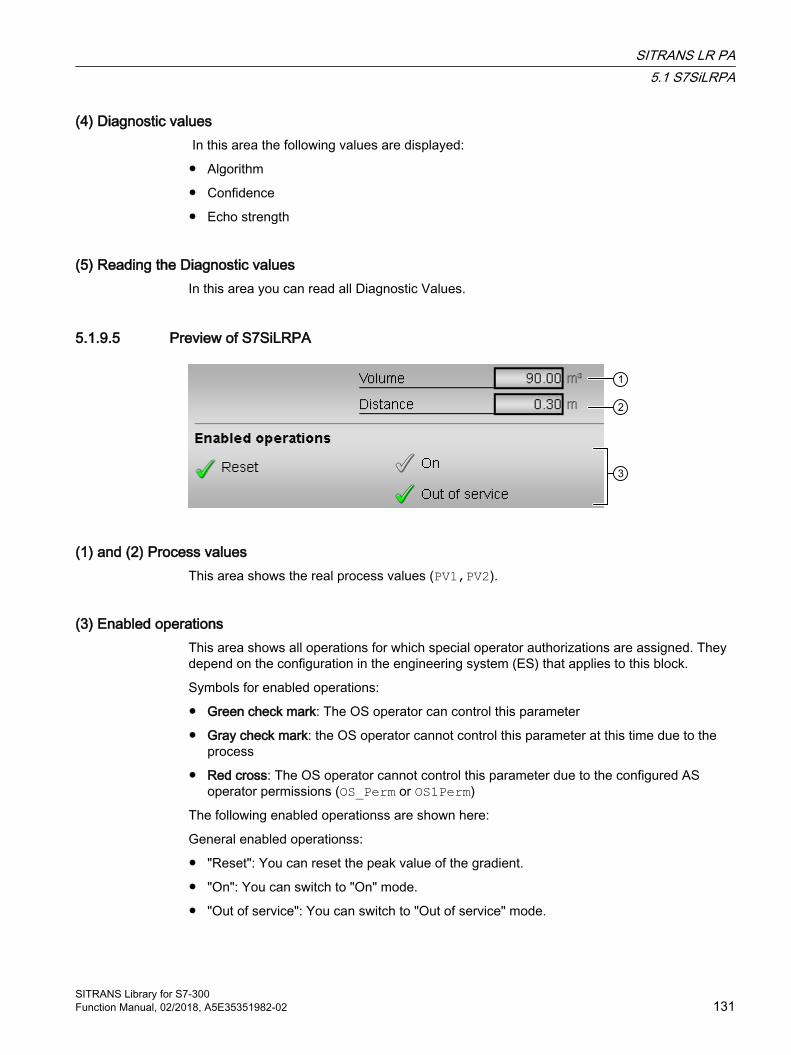
(4) Diagnostic values In this area the following values are displayed:
● Algorithm
● Confidence
● Echo strength
(5) Reading the Diagnostic valuesIn this area you can read all Diagnostic Values.
5.1.9.5 Preview of S7SiLRPA
(1) and (2) Process valuesThis area shows the real process values (PV1,PV2).
(3) Enabled operationsThis area shows all operations for which special operator authorizations are assigned. They depend on the configuration in the engineering system (ES) that applies to this block.
Symbols for enabled operations:
● Green check mark: The OS operator can control this parameter
● Gray check mark: the OS operator cannot control this parameter at this time due to the process
● Red cross: The OS operator cannot control this parameter due to the configured AS operator permissions (OS_Perm or OS1Perm)
The following enabled operationss are shown here:
General enabled operationss:
● "Reset": You can reset the peak value of the gradient.
● "On": You can switch to "On" mode.
● "Out of service": You can switch to "Out of service" mode.
SITRANS LR PA5.1 S7SiLRPA
SITRANS Library for S7-300Function Manual, 02/2018, A5E35351982-02 131
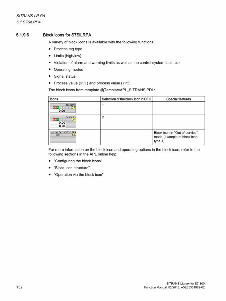
5.1.9.6 Block icons for S7SiLRPA A variety of block icons is available with the following functions:
● Process tag type
● Limits (high/low)
● Violation of alarm and warning limits as well as the control system fault CSF● Operating modes
● Signal status
● Process value (PV1) and process value (PV2)
The block icons from template @TemplateAPL_SITRANS.PDL:
Icons Selection of the block icon in CFC Special features1
2
- Block icon in "Out of service" mode (example of block icon type 1)
For more information on the block icon and operating options in the block icon, refer to the following sections in the APL online help:
● "Configuring the block icons"
● "Block icon structure"
● "Operation via the block icon"
SITRANS LR PA5.1 S7SiLRPA
SITRANS Library for S7-300132 Function Manual, 02/2018, A5E35351982-02
SITRANS P PA 66.1 S7SiP_PA
6.1.1 Description of S7SiP_PA
Object name (type + number) and family Type + number: FB 2641
Family: Sitrans
Area of application for S7SiP_PA The block is used for the following applications:
● Interface block between the Profibus PA driver blocks of the SITRANS P300 PA/DSIII PA modules (referred to below as SITRANS P) for the user program and visualization
How it works The S7SiP_PA block prepares the process data received from driver blocks from a SITRANS P and makes the data available for further use in the user program and for visualization. Data entered in the faceplate or via the block inputs is transferred to the SITRANS P by means of driver blocks.
The function block supports the configuration of the SitransP with and without totalizer.
Configuration Use the CFC editor to install the block in a cyclic interrupt OB (OB30 to OB38). The block is also installed automatically in the startup OB (OB 100). Moreover, to connect the I/O signals it is imperative to call each of the driver blocks FbAnIn (cyclic data) and PiDr64 (acyclic data) in the same cyclic interrupt OB and startup OB (OB100) before the SitP_PA block is called. The output structure AcyclData of the PiDr64 block is interconnected to the input with the same name of the S7SiP_PA block.
The module with which communication takes place is set at the DevType input. Feature bit 7 = TRUE means that the block takes over the message limits when reading the configuration data from the device.
The maximum and minimum values for the alarm and warning thresholds of the process value are configured at the input PV_OpScaleH/L.
SITRANS Library for S7-300Function Manual, 02/2018, A5E35351982-02 133
The S7SiP_PA contains two templates for process tag types as an example with an application scenario for the SITRANS Library block with and without totalizer, Template of S7SiP_PA (Page 155)
Note
The user text library "S7SiP_PA_MeasVal" must be copied from the Sitrans Library to the STEP 7 project prior to the OS compilation. To do this, open the SITRANS Library from the Simatic Manager using File -> Open... -> Libraries. Copy the "S7SiP_PA_MeasVal" file from the library (directory: Blocks+Templates\Text Libraries) into a user text library folder created using the S7 program in your STEP 7 project.
Startup characteristics Use the Feature Bit Setting the startup characteristics (Page 24) to define the startup characteristics of this block.
The messages are suppressed after startup for the number of cycles set at RunUpCyc.
Status word allocation for Status1 parameter You can find a description for each parameter in section I/Os of S7SiP_PA (Page 146).
Status bit Parameter0 Occupied1 BatchEn2 Not used3 OosAct4 OosLi5 AutAct6 LocalAct7 Mode switchover error8 OnAct9 Invalid signal status
10 - 19 Not used20 Enable local operator authorization21 Not used22 Current totalizer command 1= Positive and negative23 Current totalizer command 1= Positive24 Current totalizer command 1= Negative25 Current totalizer command 1= Hold26 Automatic preview totalizer command 1= Positive and negative27 Automatic preview totalizer command 1 = Positive28 Automatic preview totalizer command 1= Negative29 Automatic preview totalizer command 1= Hold
30 - 31 Not used
SITRANS P PA6.1 S7SiP_PA
SITRANS Library for S7-300134 Function Manual, 02/2018, A5E35351982-02
Status word allocation for Status2 parameter
Status bit Parameter0 MsgLock1 PV_AH_Act2 PV_WH_Act3 PV_WL_Act4 PV_AL_Act
5 - 6 Not used7 PV_AH_En8 PV_WH_En
9 - 10 Not used11 PV_WL_En12 PV_AL_En13 PV_AH_MsgEn14 PV_WH_MsgEn
15 - 16 Not used17 PV_WL_MsgEn18 PV_AL_MsgEn19 GradHUpAct20 GradHDnAct21 GradLAct22 GradHUpEn23 GradHDnEn24 GradLEn25 GradHUpMsgEn26 GradHDnMsgEn27 GradLMsgEn28 0 = decreasing measured value
1 = increasing measured value29 - 31 Not used
Status word allocation for Status3 parameter
Status bit Parameter0 - 7 Not used
8 Tot_AH_Act9 Tot_WH_Act10 Tot_WL_Act11 Tot_AL_Act12 Tot_AH_En13 Tot_WH_En14 0 = When Feature Bit 7 is 0 or totalizer is not configured16 Tot_WL_En
SITRANS P PA6.1 S7SiP_PA
SITRANS Library for S7-300Function Manual, 02/2018, A5E35351982-02 135
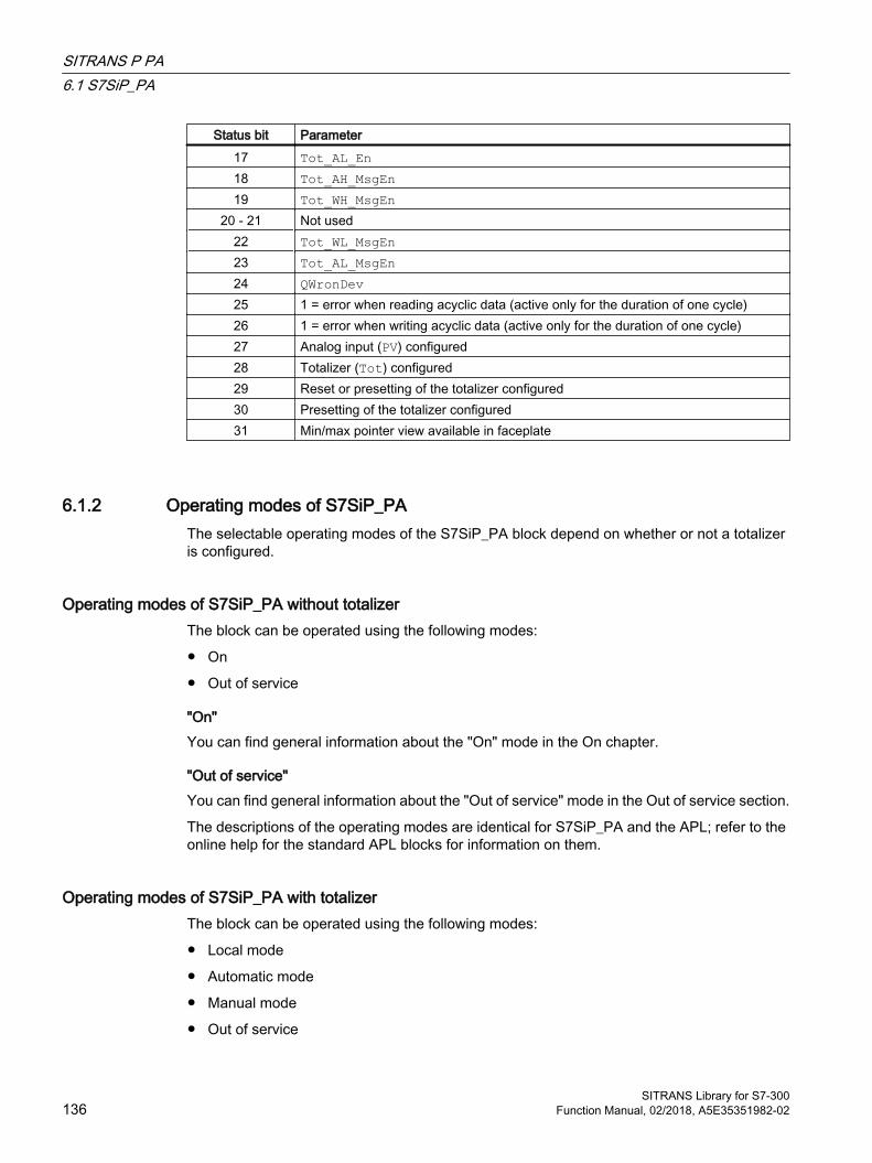
Status bit Parameter17 Tot_AL_En18 Tot_AH_MsgEn19 Tot_WH_MsgEn
20 - 21 Not used22 Tot_WL_MsgEn23 Tot_AL_MsgEn24 QWronDev 25 1 = error when reading acyclic data (active only for the duration of one cycle)26 1 = error when writing acyclic data (active only for the duration of one cycle)27 Analog input (PV) configured28 Totalizer (Tot) configured29 Reset or presetting of the totalizer configured30 Presetting of the totalizer configured31 Min/max pointer view available in faceplate
6.1.2 Operating modes of S7SiP_PAThe selectable operating modes of the S7SiP_PA block depend on whether or not a totalizer is configured.
Operating modes of S7SiP_PA without totalizer The block can be operated using the following modes:
● On
● Out of service
"On"You can find general information about the "On" mode in the On chapter.
"Out of service"You can find general information about the "Out of service" mode in the Out of service section.
The descriptions of the operating modes are identical for S7SiP_PA and the APL; refer to the online help for the standard APL blocks for information on them.
Operating modes of S7SiP_PA with totalizer The block can be operated using the following modes:
● Local mode
● Automatic mode
● Manual mode
● Out of service
SITRANS P PA6.1 S7SiP_PA
SITRANS Library for S7-300136 Function Manual, 02/2018, A5E35351982-02
The general descriptions of the operating modes are identical for S7SiP_PA and the APL; refer to the online help for the standard APL blocks for information on them.
The next section provides additional block-specific information relating to the general descriptions.
"Local mode""Local mode" supports the transfer of the following commands to the totalizer:
● "Positive and negative" (positive edge BalLocal)
● "Positive" (positive edge PosLocal)
● "Negative" (positive edge NegLocal)
● "Hold" (HoldLocal)
If you set the block to "Local mode", the control is only influenced by the "local" signals of the counters (input parameters BalLocal = 1, PosLocal = 1, NegLocal = 1 and HoldLocal = 1).
Note
Unlike the general description, at the LocalSetting parameter only the values 0, 1 and 3 can be set. Tracking in "local" mode is not possible with S7SiP_PA.
"Automatic mode""Automatic mode" supports the transfer of the following commands to the totalizer:
● "Positive and negative" (positive edge BalAut)
● "Positive" (positive edge PosAut)
● "Negative" (positive edge NegAut)
● "Hold" (HoldAut = 1)
"Manual mode""Manual mode" supports the transfer of the following commands to the totalizer:
● "Positive and negative" (positive edge BalMan)
● "Positive" (positive edge PosMan)
● "Negative" (positive edge NegMan)
● "Hold" (HoldMan = 1)
"Out of service"For general information about the "out of service" mode, refer to the APL Online Help.
6.1.3 S7SiP_PA functionsThe functions for this block are listed below.
SITRANS P PA6.1 S7SiP_PA
SITRANS Library for S7-300Function Manual, 02/2018, A5E35351982-02 137
Configuration data The configuration data comprises the units, the configuration of PV input and the limits for messages. After a change is made in the device, reading of configuration data must be triggered with "Read configuration data" in the parameter view of the faceplate. If the parameters were read back before a complete download to the PLC, the configuration does not need to be reloaded from the device.
The message limits of the S7SiP_PA are only transferred to the device when the alarm configuration is synchronized with the device (Feature bit7 = TRUE).
The S7SiP_PA function block has the following configuration data which can be read out of the SitransP by means of the "Read configuration data" command:
Description Block parameters (I/O)Configuration input PV PV_MeasUnits PV and Tot, min/max pointer pressure, sen‐sor and electronics temperature
PV_UnitTot_Unit PMM_UnitSenTempUnitElecTempUnit
Limits PV InPV_AH_Lim/PV_AH_LimInPV_WH_Lim/PV_WH_LimInPV_WL_Lim/PV_WL_LimInPV_AL_Lim/PV_AL_LimInPV_Hyst/PV_Hyst
Limits Tot InTot_AH_Lim/Tot_AH_LimInTot_WH_Lim/Tot_WH_LimInTot_WL_Lim/Tot_WL_LimInTot_AL_Lim/v_AL_Lim InTot_Hyst/Tot_Hyst
Default InPreVal/PreVal
Limit monitoringThe block monitors the process value PV and, if configured, the totalizer value Tot for limits. Both values are cyclically integrated into the process image of the controller. Configuration of the limits is carried out either by means of PDM and imported by reading the configuration data from the block, or can be carried out on the block independent of the module (see Feature bit 7).
You can monitor the process value PV and the totalizer value Tot for the following high and low alarm and warning thresholds:
● PV/Tot_AH_Lim: Limit for high alarm
● PV/Tot_AL_Lim: Limit for low alarm
● PV/Tot_Hyst: Hysteresis
● PV/Tot_WH_Lim: Limit for high warning
● PV/Tot_WL_Lim: Limit for low warning
SITRANS P PA6.1 S7SiP_PA
SITRANS Library for S7-300138 Function Manual, 02/2018, A5E35351982-02
The result of limit monitoring is returned at the interconnectable output parameters:
● PV/Tot_AH_Act = 1: Limit for high alarm reached or exceeded
● PV/Tot_AL_Act = 1: Limit for low alarm reached or undershot
● PV/Tot_WH_Act = 1: Limit for high warning reached or exceeded
● PV/Tot_WL_Act = 1: Limit for low warning reached or undershot
Monitoring is always enabled using the input parameters:
● PV/Tot_AH_En = 1: Monitoring of the high alarm limits
● PV/Tot_AL_En = 1: Monitoring of the low alarm limits
● PV/Tot_WH_En = 1: Monitoring of the high warning limits
● PV/Tot_WL_En = 1: Monitoring of the low warning limits
The corresponding message is suppressed using the parameters:
● PV/Tot_AH_MsgEn = 0: Alarm (high) messages are suppressed
● PV/Tot_AL_MsgEn = 0: Alarm (low) messages are suppressed
● PV/Tot_WH_MsgEn = 0: Warning (high) messages are suppressed
● PV/Tot_WL_MsgEn = 0: Warning (low) messages are suppressed
You can define a hysteresis (PVTot_Hyst) for the limits, for example to suppress signal flatter. You can also modify the limits and hysteresis via the faceplate.
Gradient monitoringThe gradient PV_Grad is calculated by means of a delay function configurable using LagTime. During calculation of the gradient, jumps in the input value PV are smoothed.
The peak values of the gradient are output in the output parameters PV_GradNP (negative gradient) and PV_GradPP (positive gradient). These are reset when the operator enters the corresponding command for resetting.
The slope of the gradient PV_Grad can be monitored for the following limits:
● Limit (high) for the positive gradient (GradHUpLim)
● Limit (high) for the negative gradient ((GradHDnLim)
● Limit (low) for the absolute gradient (GradLLim)
Activation of the individual monitoring functions is carried out at the corresponding "Enable" parameters, e.g. GradHUpEn for activating the high gradient limit for positive gradients (GradHUpLim).
Reaching or violation of your defined limits is indicated at the corresponding "Active" output parameters, e.g. by means of GradHUpAct = 1 for the limit (high) for the positive gradient.
SITRANS P PA6.1 S7SiP_PA
SITRANS Library for S7-300Function Manual, 02/2018, A5E35351982-02 139
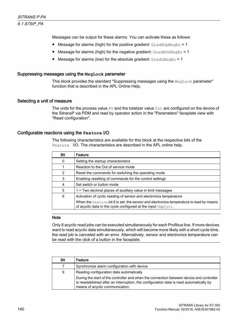
Messages can be output for these alarms. You can activate these as follows:
● Message for alarms (high) for the positive gradient: GradHUpMsgEn = 1
● Message for alarms (high) for the negative gradient: GradHDnMsgEn = 1
● Message for alarms (low) for the absolute gradient: GradLMsgEn = 1
Suppressing messages using the MsgLock parameterThis block provides the standard "Suppressing messages using the MsgLock parameter" function that is described in the APL Online Help.
Selecting a unit of measureThe units for the process value PV and the totalizer value Tot are configured on the device of the SitransP via PDM and read by operator action in the "Parameters" faceplate view with "Read configuration".
Configurable reactions using the Feature I/OThe following characteristics are available for this block at the respective bits of the Feature I/O. The characteristics are described in the APL online help.
Bit Feature0 Setting the startup characteristics1 Reaction to the Out of service mode2 Reset the commands for switching the operating mode3 Enabling resetting of commands for the control settings4 Set switch or button mode5 1 = Two decimal places of auxillary value in limit messages6 Activation of cyclic reading of sensor and electronics temperature
When the Feature bit 6 is set, the sensor and electronics temperature is read by means of acyclic data in the cycle configured at the input TmpCycl.
Note
Only 8 acyclic read jobs can be executed simultaneously for each Profibus line. If more devices want to read acyclic data simultaneously, which will become more likely with a short cycle time, the read job is canceled with an error. Alternatively, sensor and electronics temperature can be read with the click of a button in the faceplate.
Bit Feature7 Synchronize alarm configuration with device9 Reading configuration data automatically
During the start of the controller and when the connection between device and controller is reestablished after an interruption, the configuration data is read automatically by means of acyclic communication.
SITRANS P PA6.1 S7SiP_PA
SITRANS Library for S7-300140 Function Manual, 02/2018, A5E35351982-02
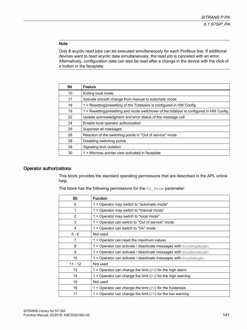
Note
Only 8 acyclic read jobs can be executed simultaneously for each Profibus line. If additional devices want to read acyclic data simultaneously, the read job is canceled with an error. Alternatively, configuration data can also be read after a change in the device with the click of a button in the faceplate.
Bit Feature10 Exiting local mode17 Activate smooth change from manual to automatic mode18 1 = Resetting/presetting of the Totalizers is configured in HW Config19 1 = Resetting/presetting and mode switchover of the totalizer is configured in HW Config22 Update acknowledgment and error status of the message call24 Enable local operator authorization25 Suppress all messages26 Reaction of the switching points in "Out of service" mode28 Disabling switching points29 Signaling limit violation30 1 = Min/max pointer view activated in faceplate
Operator authorizationsThis block provides the standard operating permissions that are described in the APL online help.
The block has the following permissions for the OS_Perm parameter:
Bit Function0 1 = Operator may switch to "automatic mode"1 1 = Operator may switch to "manual mode"2 1 = Operator may switch to "local mode"3 1 = Operator can switch to "Out of service" mode4 1 = Operator can switch to "On" mode
5 - 6 Not used7 1 = Operator can reset the maximum values8 1 = Operator can activate / deactivate messages with GradHUpMsgEn 9 1 = Operator can activate / deactivate messages with GradHDnMsgEn
10 1 = Operator can activate / deactivate messages with GradLMsgEn11 - 12 Not used
13 1 = Operator can change the limit (PV) for the high alarm14 1 = Operator can change the limit (PV) for the high warning15 Not used16 1 = Operator can change the limit (PV) for the hysteresis17 1 = Operator can change the limit (PV) for the low warning
SITRANS P PA6.1 S7SiP_PA
SITRANS Library for S7-300Function Manual, 02/2018, A5E35351982-02 141

18 1 = Operator can change the limit (PV) for the low alarm19 Not used20 1 = Operator can change the value for the high gradient limit for positive gradients
(GradHUpLim)21 1 = Operator can change the value for the high gradient limit for negative gradients
(GradHDnLim)22 1 = Operator can change the value for the low gradient limit for positive and negative
gradients (GradLLim)23 Not used24 1 = Operator can activate / deactivate messages with PV_AH_MsgEn25 1 = Operator can activate / deactivate messages with PV_WH_MsgEn26 1 = Operator can activate / deactivate messages with PV_WL_MsgEn27 1 = Operator can activate / deactivate messages with PV_AL_MsgEn
28 - 31 Not used
The block has the following permissions for the OS1Perm parameter:
Bit Function0 1 = Operator can change the limit (Tot) for the high alarm1 1 = Operator can change the limit (Tot) for the high warning2 1 = Operator can change the limit (Tot) for the hysteresis3 1 = Operator can change the limit (Tot) for the low warning4 1 = Operator can change the limit (Tot) for the low alarm5 1 = Operator can activate / deactivate messages with Tot_AH_MsgEn6 1 = Operator can activate / deactivate messages with Tot_WH_MsgEn7 1 = Operator can activate / deactivate messages with Tot_WL_MsgEn8 1 = Operator can activate / deactivate messages with Tot_AL_MsgEn9 1 = Operator may input the 'positive and negative count' totalizer command10 1 = Operator may input the 'only positive count' totalizer command11 1 = Operator may input the 'only negative count' totalizer command12 1 = Operator may input the 'Hold' totalizer command13 1 = Operator can reset the totalizer14 1 = Operator can preset the totalizer15 1 = Operator can read the configuration data from the device16 1 = Operator can write the configuration data to the device17 1 = Operator can read the min/max pointer values from the module18 1 = Operator can reset the maximum min/max pointer value of the pressure19 1 = Operator can reset the minimum min/max pointer value of the pressure20 1 = Operator can reset the maximum min/max pointer value of the sensor temper‐
ature21 1 = Operator can reset the minimum min/max pointer value of the sensor temper‐
ature22 1 = Operator can reset the maximum min/max pointer value of the electronics tem‐
perature23 1 = Operator can reset the minimum min/max pointer value of the electronics tem‐
perature
SITRANS P PA6.1 S7SiP_PA
SITRANS Library for S7-300142 Function Manual, 02/2018, A5E35351982-02
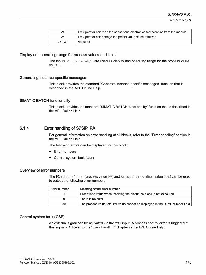
24 1 = Operator can read the sensor and electronics temperature from the module25 1 = Operator can change the preset value of the totalizer
26 - 31 Not used
Display and operating range for process values and limitsThe inputs PV_OpScaleH/L are used as display and operating range for the process value PV_In .
Generating instance-specific messagesThis block provides the standard "Generate instance-specific messages" function that is described in the APL Online Help.
SIMATIC BATCH functionalityThis block provides the standard "SIMATIC BATCH functionality" function that is described in the APL Online Help.
6.1.4 Error handling of S7SiP_PAFor general information on error handling at all blocks, refer to the "Error handling" section in the APL Online Help.
The following errors can be displayed for this block:
● Error numbers
● Control system fault (CSF)
Overview of error numbersThe I/Os Error0Num (process value PV) and Error1Num (totalizer value Tot) can be used to output the following error numbers:
Error number Meaning of the error number-1 Predefined value when inserting the block; the block is not executed.0 There is no error.30 The process value/totalizer value cannot be displayed in the REAL number field
Control system fault (CSF)An external signal can be activated via the CSF input. A process control error is triggered if this signal = 1. Refer to the "Error handling" chapter in the APL Online Help.
SITRANS P PA6.1 S7SiP_PA
SITRANS Library for S7-300Function Manual, 02/2018, A5E35351982-02 143
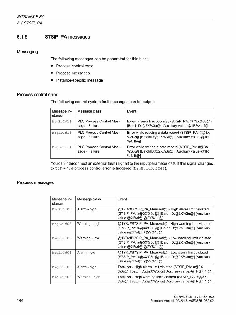
6.1.5 S7SiP_PA messages
MessagingThe following messages can be generated for this block:
● Process control error
● Process messages
● Instance-specific message
Process control error The following control system fault messages can be output:
Message in‐stance
Message class Event
MsgEvId12
PLC Process Control Mes‐sage - Failure
External error has occurred (S7SiP_PA: #@3X%3u@) [BatchID:@2X%3u@] [Auxiliary value:@1R%4.1f@]
MsgEvId13 PLC Process Control Mes‐sage - Failure
Error while reading a data record (S7SiP_PA: #@3X%3u@) [BatchID:@2X%3u@] [Auxiliary value:@1R%4.1f@]
MsgEvId14 PLC Process Control Mes‐sage - Failure
Error while writing a data record (S7SiP_PA: #@3X%3u@) [BatchID:@2X%3u@] [Auxiliary value:@1R%4.1f@]
You can interconnect an external fault (signal) to the input parameter CSF. If this signal changes to CSF = 1, a process control error is triggered (MsgEvld3, SIG4).
Process messages
Message in‐stance
Message class Event
MsgEvId01 Alarm - high @1Y%t#S7SiP_PA_MeasVal@ - High alarm limit violated (S7SiP_PA: #@3X%3u@) [BatchID:@2X%3u@] [Auxiliary value:@2I%d@.@2Y%1u@]
MsgEvId02 Warning - high @1Y%t#S7SiP_PA_MeasVal@ - High warning limit violated (S7SiP_PA: #@3X%3u@) [BatchID:@2X%3u@] [Auxiliary value:@2I%d@.@2Y%1u@]
MsgEvId03 Warning - low @1Y%t#S7SiP_PA_MeasVal@ - Low warning limit violated (S7SiP_PA: #@3X%3u@) [BatchID:@2X%3u@] [Auxiliary value:@2I%d@.@2Y%1u@]
MsgEvId04 Alarm - low @1Y%t#S7SiP_PA_MeasVal@ - Low alarm limit violated (S7SiP_PA: #@3X%3u@) [BatchID:@2X%3u@] [Auxiliary value:@2I%d@.@2Y%1u@]
MsgEvId05 Alarm - high Totalizer - High alarm limit violated (S7SiP_PA: #@3X%3u@) [BatchID:@2X%3u@] [Auxiliary value:@1R%4.1f@]
MsgEvId06 Warning - high Totalizer - High warning limit violated (S7SiP_PA: #@3X%3u@) [BatchID:@2X%3u@] [Auxiliary value:@1R%4.1f@]
SITRANS P PA6.1 S7SiP_PA
SITRANS Library for S7-300144 Function Manual, 02/2018, A5E35351982-02
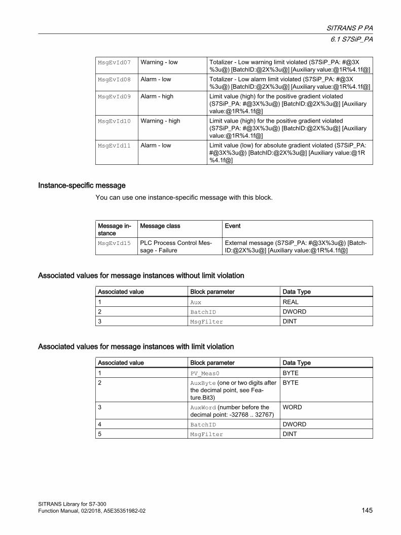
MsgEvId07 Warning - low Totalizer - Low warning limit violated (S7SiP_PA: #@3X%3u@) [BatchID:@2X%3u@] [Auxiliary value:@1R%4.1f@]
MsgEvId08 Alarm - low Totalizer - Low alarm limit violated (S7SiP_PA: #@3X%3u@) [BatchID:@2X%3u@] [Auxiliary value:@1R%4.1f@]
MsgEvId09 Alarm - high Limit value (high) for the positive gradient violated (S7SiP_PA: #@3X%3u@) [BatchID:@2X%3u@] [Auxiliary value:@1R%4.1f@]
MsgEvId10 Warning - high Limit value (high) for the positive gradient violated (S7SiP_PA: #@3X%3u@) [BatchID:@2X%3u@] [Auxiliary value:@1R%4.1f@]
MsgEvId11 Alarm - low Limit value (low) for absolute gradient violated (S7SiP_PA: #@3X%3u@) [BatchID:@2X%3u@] [Auxiliary value:@1R%4.1f@]
Instance-specific message You can use one instance-specific message with this block.
Message in‐stance
Message class Event
MsgEvId15 PLC Process Control Mes‐sage - Failure
External message (S7SiP_PA: #@3X%3u@) [Batch‐ID:@2X%3u@] [Auxiliary value:@1R%4.1f@]
Associated values for message instances without limit violation
Associated value Block parameter Data Type1 Aux REAL2 BatchID DWORD3 MsgFilter DINT
Associated values for message instances with limit violation
Associated value Block parameter Data Type1 PV_Meas0 BYTE2 AuxByte (one or two digits after
the decimal point, see Fea‐ture.Bit3)
BYTE
3 AuxWord (number before the decimal point: -32768 .. 32767)
WORD
4 BatchID DWORD5 MsgFilter DINT
SITRANS P PA6.1 S7SiP_PA
SITRANS Library for S7-300Function Manual, 02/2018, A5E35351982-02 145

Message texts and their text numbersThe following table shows the message texts and their text numbers in the text library "S7SiP_PA_MeasVal" for the S7SiP_PA block (FB 2641):
Text number Message text1 <Invalid value>2 Pressure3 Volumetric flow4 Mass flow5 Level6 Volume7 Pressure (untrimmed)8 Sensor temperature9 Electronics temperature
6.1.6 I/Os of S7SiP_PA
Input parameters
Parameter Description Type DefaultDevType Device type of SITRANS P
1: SitransP DSIII PA1: SitransP P300 PA
INT 0
PV Process value BYTE 16#80QCPV Quality Code of Process Value BYTE 16#80Tot Totalizer value BYTE 16#80QCTot Quality Code of Totalizer BYTE 16#80PV_Meas* Measured value that is interconnected
at the PV input:0: <invalid value>1: Pressure2: Volume flow3: Mass flow4: Fill level5: Volume6: Pressure (untrimmed)7: Sensor temperature8: Electronics temperature
BYTE 0
ChannelAI* Channel (read by device) INT -1AppSwitch* Measuring mode switch (read by device) INT -1PV_Unit* Measurement unit for process value
(PV)INT 0
Tot_Unit* Measurement unit for totalizer value (Tot)
INT 0
SITRANS P PA6.1 S7SiP_PA
SITRANS Library for S7-300146 Function Manual, 02/2018, A5E35351982-02
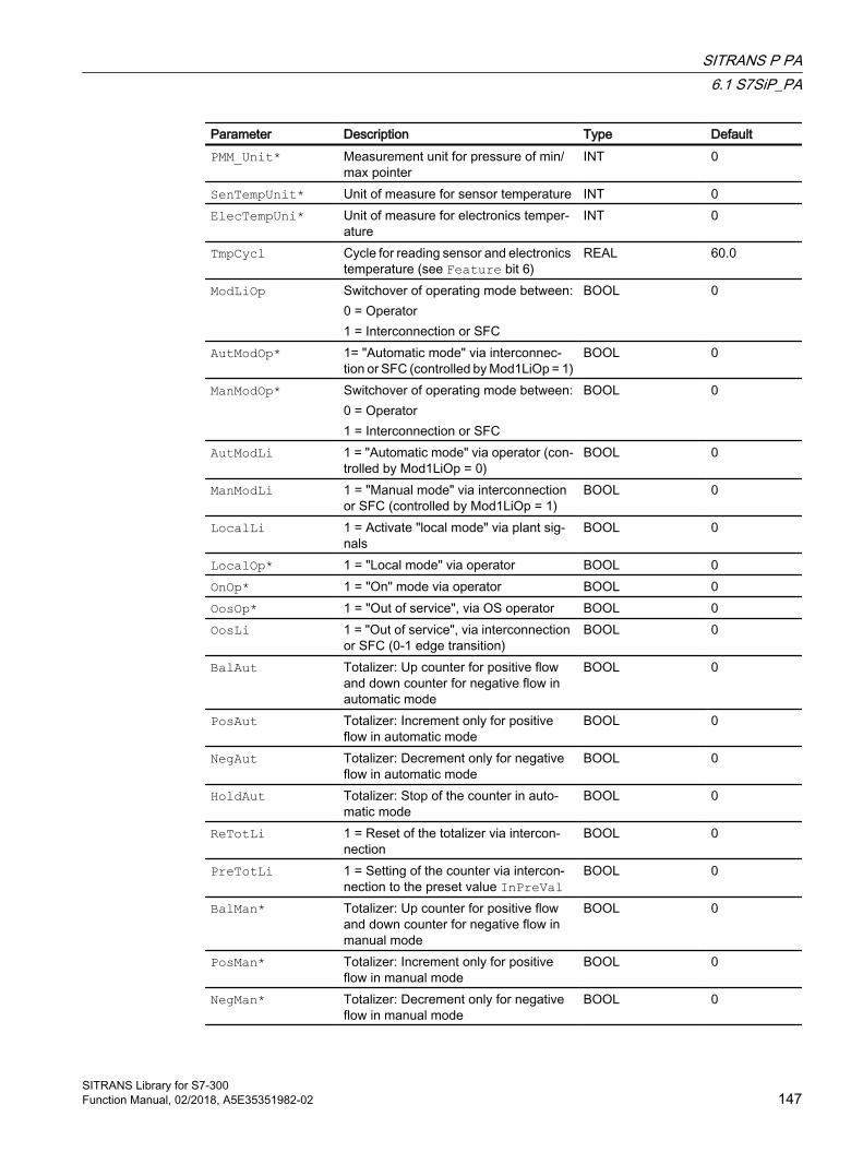
Parameter Description Type DefaultPMM_Unit* Measurement unit for pressure of min/
max pointerINT 0
SenTempUnit* Unit of measure for sensor temperature INT 0ElecTempUni* Unit of measure for electronics temper‐
atureINT 0
TmpCycl Cycle for reading sensor and electronics temperature (see Feature bit 6)
REAL 60.0
ModLiOp Switchover of operating mode between:0 = Operator1 = Interconnection or SFC
BOOL 0
AutModOp* 1= "Automatic mode" via interconnec‐tion or SFC (controlled by Mod1LiOp = 1)
BOOL 0
ManModOp* Switchover of operating mode between:0 = Operator1 = Interconnection or SFC
BOOL 0
AutModLi 1 = "Automatic mode" via operator (con‐trolled by Mod1LiOp = 0)
BOOL 0
ManModLi 1 = "Manual mode" via interconnection or SFC (controlled by Mod1LiOp = 1)
BOOL 0
LocalLi 1 = Activate "local mode" via plant sig‐nals
BOOL 0
LocalOp* 1 = "Local mode" via operator BOOL 0OnOp* 1 = "On" mode via operator BOOL 0OosOp* 1 = "Out of service", via OS operator BOOL 0OosLi 1 = "Out of service", via interconnection
or SFC (0-1 edge transition)BOOL 0
BalAut Totalizer: Up counter for positive flow and down counter for negative flow in automatic mode
BOOL 0
PosAut Totalizer: Increment only for positive flow in automatic mode
BOOL 0
NegAut Totalizer: Decrement only for negative flow in automatic mode
BOOL 0
HoldAut Totalizer: Stop of the counter in auto‐matic mode
BOOL 0
ReTotLi 1 = Reset of the totalizer via intercon‐nection
BOOL 0
PreTotLi 1 = Setting of the counter via intercon‐nection to the preset value InPreVal
BOOL 0
BalMan* Totalizer: Up counter for positive flow and down counter for negative flow in manual mode
BOOL 0
PosMan* Totalizer: Increment only for positive flow in manual mode
BOOL 0
NegMan* Totalizer: Decrement only for negative flow in manual mode
BOOL 0
SITRANS P PA6.1 S7SiP_PA
SITRANS Library for S7-300Function Manual, 02/2018, A5E35351982-02 147
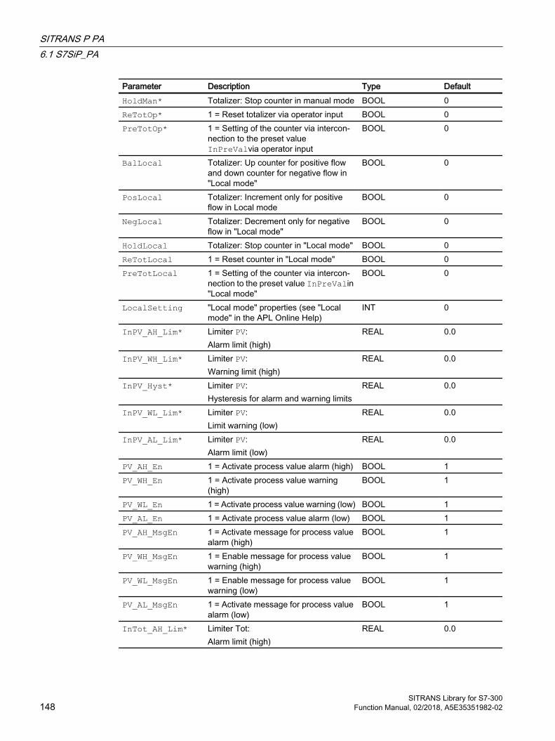
Parameter Description Type DefaultHoldMan* Totalizer: Stop counter in manual mode BOOL 0ReTotOp* 1 = Reset totalizer via operator input BOOL 0PreTotOp* 1 = Setting of the counter via intercon‐
nection to the preset value InPreValvia operator input
BOOL 0
BalLocal Totalizer: Up counter for positive flow and down counter for negative flow in "Local mode"
BOOL 0
PosLocal Totalizer: Increment only for positive flow in Local mode
BOOL 0
NegLocal Totalizer: Decrement only for negative flow in "Local mode"
BOOL 0
HoldLocal Totalizer: Stop counter in "Local mode" BOOL 0ReTotLocal 1 = Reset counter in "Local mode" BOOL 0PreTotLocal 1 = Setting of the counter via intercon‐
nection to the preset value InPreValin "Local mode"
BOOL 0
LocalSetting "Local mode" properties (see "Local mode" in the APL Online Help)
INT 0
InPV_AH_Lim* Limiter PV:Alarm limit (high)
REAL 0.0
InPV_WH_Lim* Limiter PV:Warning limit (high)
REAL 0.0
InPV_Hyst* Limiter PV:Hysteresis for alarm and warning limits
REAL 0.0
InPV_WL_Lim* Limiter PV:Limit warning (low)
REAL 0.0
InPV_AL_Lim* Limiter PV:Alarm limit (low)
REAL 0.0
PV_AH_En 1 = Activate process value alarm (high) BOOL 1PV_WH_En 1 = Activate process value warning
(high)BOOL 1
PV_WL_En 1 = Activate process value warning (low) BOOL 1PV_AL_En 1 = Activate process value alarm (low) BOOL 1PV_AH_MsgEn 1 = Activate message for process value
alarm (high)BOOL 1
PV_WH_MsgEn 1 = Enable message for process value warning (high)
BOOL 1
PV_WL_MsgEn 1 = Enable message for process value warning (low)
BOOL 1
PV_AL_MsgEn 1 = Activate message for process value alarm (low)
BOOL 1
InTot_AH_Lim* Limiter Tot:Alarm limit (high)
REAL 0.0
SITRANS P PA6.1 S7SiP_PA
SITRANS Library for S7-300148 Function Manual, 02/2018, A5E35351982-02

Parameter Description Type DefaultInTot_WH_Lim* Limiter Tot:
Warning limit (high)REAL 0.0
InTot_Hyst* Limiter Tot:Hysteresis for alarm and warning limits
REAL 0.0
InTot_WL_Lim* Limiter Tot:Limit warning (low)
REAL 0.0
InTot_AL_Lim* Limiter Tot:Alarm limit (low)
REAL 0.0
InPreVal Presetting value for totalizer REAL 0.0Tot_AH_En 1 = Enable totalizer alarm (high) BOOL 1Tot_WH_En 1 = Enable totalizer warning (high) BOOL 1Tot_WL_En 1 = Enable totalizer warning (low) BOOL 1Tot_AL_En 1 = Enable totalizer alarm (low) BOOL 1Tot_AH_MsgEn 1 = Enable message for totalizer alarm
(high)BOOL 1
Tot_WH_MsgEn 1 = Enable message for totalizer warn‐ing (high)
BOOL 1
Tot_WL_MsgEn 1 = Enable message for process value warning (low)
BOOL 1
Tot_AL_MsgEn 1 = Enable message for totalizer alarm (low)
BOOL 1
GradHUpLim Gradient monitoring: Limit (high) for the positive gradient
REAL 10.0
GradHDnLim Gradient monitoring: Limit (high) for the negative gradient
REAL 10.0
GradLLim Gradient monitoring: Limit (low) for the absolute gradient
REAL 1.0
RstOp* 1 = Reset peak values of gradient via operator
BOOL 0
LagTime Delay time [s] REAL 1.0PV_OpScaleH High limit for scale in PV bar graph of
faceplateREAL 100.0
PV_OpScaleL Low Limit for scale in PV bar graph of faceplate
REAL 0.0
GradHUpEn 1 = Enable gradient monitoring (high) for positive changes
BOOL 1
GradHDnEn 1 = Enable gradient monitoring (high) for negative changes
BOOL 1
GradLEn 1 = Enable gradient monitoring (low) BOOL 0GradHUpMsgEn 1 = Enable gradient (high) message for
positive changesBOOL 1
GradHDnMsgEn 1 = Enable gradient (high) message for negative changes
BOOL 1
GradLMsgEn 1 = Enable gradient (high) message for negative changes
BOOL 1
SITRANS P PA6.1 S7SiP_PA
SITRANS Library for S7-300Function Manual, 02/2018, A5E35351982-02 149
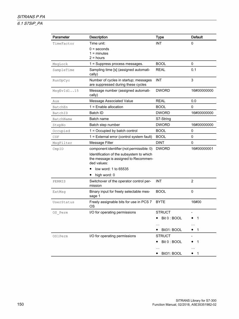
Parameter Description Type DefaultTimeFactor Time unit:
0 = seconds1 = minutes2 = hours
INT 0
MsgLock 1 = Suppress process messages. BOOL 0SampleTime Sampling time [s] (assigned automati‐
cally)REAL 0.1
RunUpCyc Number of cycles in startup; messages are suppressed during these cycles
INT 3
MsgEvId1..15 Message number (assigned automati‐cally)
DWORD 16#00000000
Aux Message Associated Value REAL 0.0BatchEn 1 = Enable allocation BOOL 0BatchID Batch ID DWORD 16#00000000BatchName Batch name S7-String StepNo Batch step number DWORD 16#00000000Occupied 1 = Occupied by batch control BOOL 0CSF 1 = External error (control system fault) BOOL 0MsgFilter Message Filter DINT 0CmpID component identifier (not permissible: 0)
Identification of the subsystem to which the message is assigned to Recommen‐ded values: ● low word: 1 to 65535● high word: 0
DWORD 16#00000001
PERMIS Switchover of the operator control per‐mission
INT 2
ExtMsg Binary input for freely selectable mes‐sage 1
BOOL 0
UserStatus Freely assignable bits for use in PCS 7 OS
BYTE 16#00
OS_Perm I/O for operating permissions STRUCT● Bit 0 : BOOL…● Bit31: BOOL
-● 1…● 1
OS1Perm I/O for operating permissions STRUCT● Bit 0 : BOOL…● Bit31: BOOL
-● 1…● 1
SITRANS P PA6.1 S7SiP_PA
SITRANS Library for S7-300150 Function Manual, 02/2018, A5E35351982-02

Parameter Description Type DefaultFeature I/O for additional functions STRUCT
● Bit 0 : BOOL● Bit 1 : BOOL● Bit 2 : BOOL…● Bit 6 : BOOL● Bit 7 : BOOL…● Bit31: BOOL
-● 0● 0● 1 ● 1● 0 ● 0
RdCfgOp* 1 = Read all configuration data from Si‐transP
BOOL 0
WrCfgOp* 1 = Write all configuration data to Si‐transP
BOOL 0
RdTmpOp* 1 = Read sensor and electronics tem‐perature from the device
BOOL 0
RdMinMax* 1 = Read all slave pointer values from the device
BOOL 0
RMaxPOp 1 = Reset max. slave pointer pressure BOOL 0RMinPOp 1 = Reset min. slave pointer pressure BOOL 0RMaxSTOp 1 = Reset max. slave pointer sensor
temperatureBOOL 0
RMinSTOp 1 = Reset min. slave pointer sensor tem‐perature
BOOL 0
RMaxETOp 1 = Reset max. slave pointer electronics temperature
BOOL 0
RMinETOp 1 = Reset min. slave pointer electronics temperature
BOOL 0
RMaxPLi 1 = Reset max. min/max pointer pres‐sure, via interconnection or SFC (0-1 edge transition)
BOOL 0
RMinPLi 1 = Reset max. min/max pointer pres‐sure, via interconnection or SFC (0-1 edge transition)
BOOL 0
RMaxSTLi 1 = Reset max. slave pointer sensor temperature, via interconnection or SFC (0-1 edge transition)
BOOL 0
RMinSTLi 1 = Reset min. slave pointer sensor tem‐perature, via interconnection or SFC (0-1 edge transition)
BOOL 0
RMaxETLi 1 = Reset max. slave pointer electronics temperature, via interconnection or SFC (0-1 edge transition)
BOOL 0
RMinETLi 1 = Reset min. slave pointer electronics temperature, via interconnection or SFC (0-1 edge transition)
BOOL 0
SITRANS P PA6.1 S7SiP_PA
SITRANS Library for S7-300Function Manual, 02/2018, A5E35351982-02 151
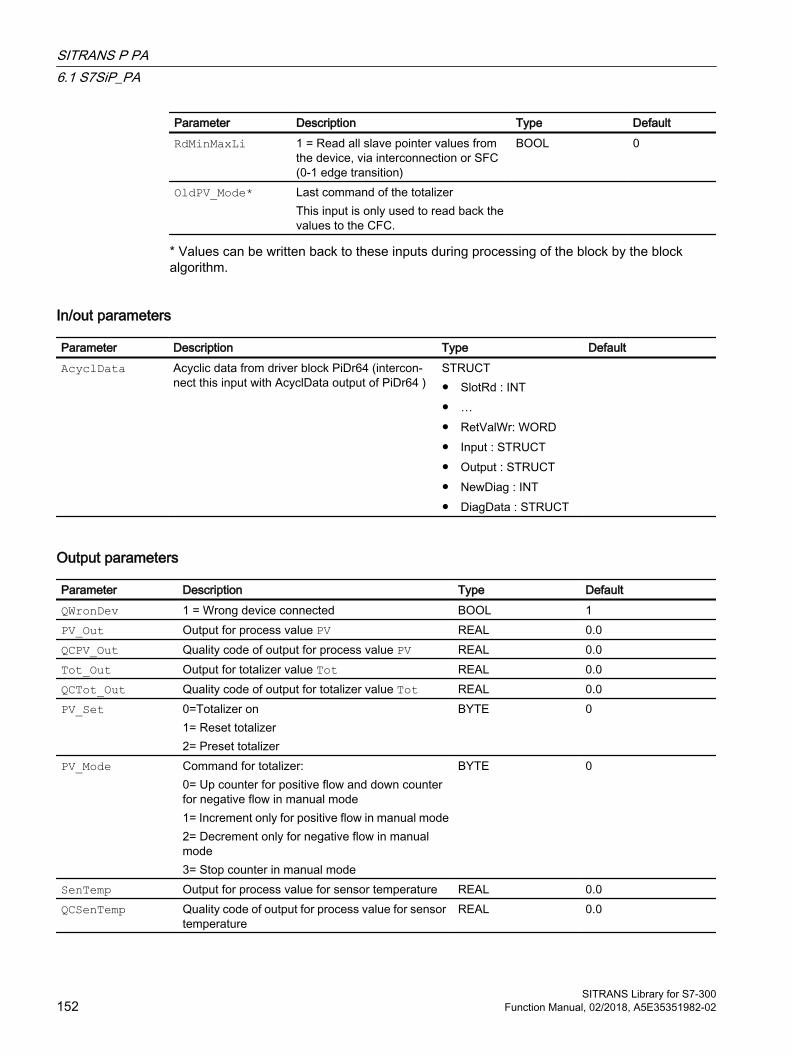
Parameter Description Type DefaultRdMinMaxLi 1 = Read all slave pointer values from
the device, via interconnection or SFC (0-1 edge transition)
BOOL 0
OldPV_Mode* Last command of the totalizerThis input is only used to read back the values to the CFC.
* Values can be written back to these inputs during processing of the block by the block algorithm.
In/out parameters
Parameter Description Type DefaultAcyclData Acyclic data from driver block PiDr64 (intercon‐
nect this input with AcyclData output of PiDr64 )STRUCT● SlotRd : INT● …● RetValWr: WORD● Input : STRUCT● Output : STRUCT● NewDiag : INT● DiagData : STRUCT
Output parameters
Parameter Description Type DefaultQWronDev 1 = Wrong device connected BOOL 1PV_Out Output for process value PV REAL 0.0QCPV_Out Quality code of output for process value PV REAL 0.0Tot_Out Output for totalizer value Tot REAL 0.0QCTot_Out Quality code of output for totalizer value Tot REAL 0.0PV_Set 0=Totalizer on
1= Reset totalizer2= Preset totalizer
BYTE 0
PV_Mode Command for totalizer:0= Up counter for positive flow and down counter for negative flow in manual mode1= Increment only for positive flow in manual mode2= Decrement only for negative flow in manual mode3= Stop counter in manual mode
BYTE 0
SenTemp Output for process value for sensor temperature REAL 0.0QCSenTemp Quality code of output for process value for sensor
temperatureREAL 0.0
SITRANS P PA6.1 S7SiP_PA
SITRANS Library for S7-300152 Function Manual, 02/2018, A5E35351982-02
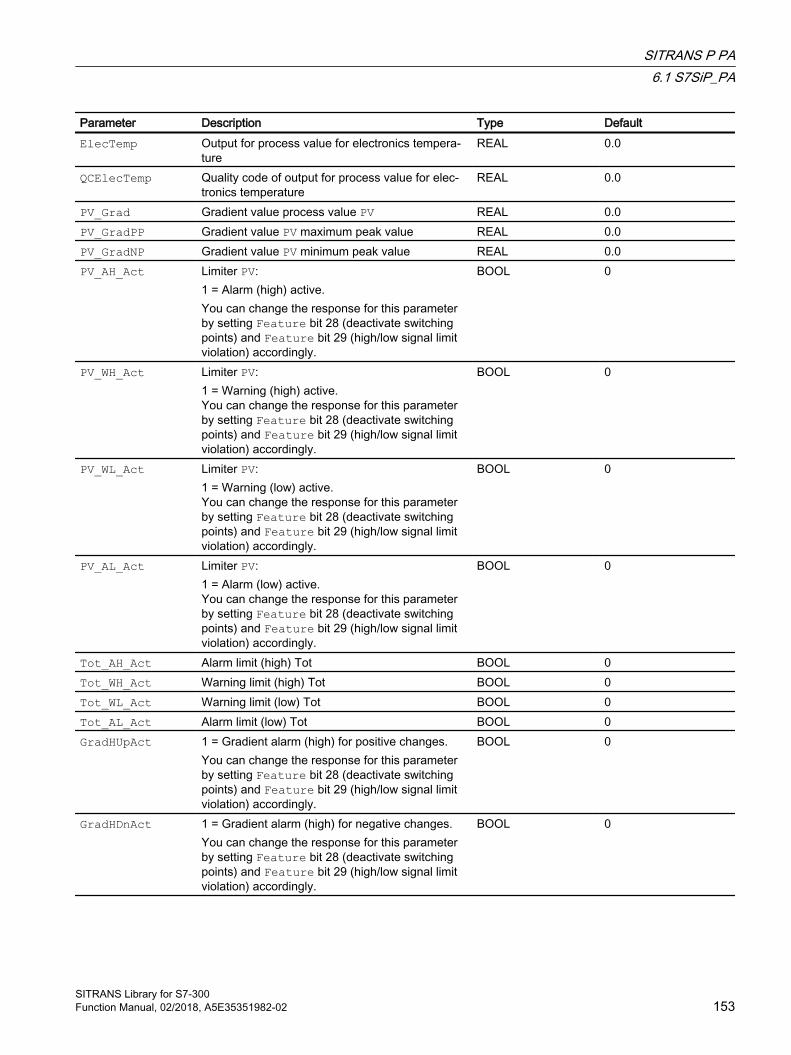
Parameter Description Type DefaultElecTemp Output for process value for electronics tempera‐
tureREAL 0.0
QCElecTemp Quality code of output for process value for elec‐tronics temperature
REAL 0.0
PV_Grad Gradient value process value PV REAL 0.0PV_GradPP Gradient value PV maximum peak value REAL 0.0PV_GradNP Gradient value PV minimum peak value REAL 0.0PV_AH_Act Limiter PV:
1 = Alarm (high) active. You can change the response for this parameter by setting Feature bit 28 (deactivate switching points) and Feature bit 29 (high/low signal limit violation) accordingly.
BOOL 0
PV_WH_Act Limiter PV:1 = Warning (high) active. You can change the response for this parameter by setting Feature bit 28 (deactivate switching points) and Feature bit 29 (high/low signal limit violation) accordingly.
BOOL 0
PV_WL_Act Limiter PV:1 = Warning (low) active. You can change the response for this parameter by setting Feature bit 28 (deactivate switching points) and Feature bit 29 (high/low signal limit violation) accordingly.
BOOL 0
PV_AL_Act Limiter PV:1 = Alarm (low) active. You can change the response for this parameter by setting Feature bit 28 (deactivate switching points) and Feature bit 29 (high/low signal limit violation) accordingly.
BOOL 0
Tot_AH_Act Alarm limit (high) Tot BOOL 0Tot_WH_Act Warning limit (high) Tot BOOL 0Tot_WL_Act Warning limit (low) Tot BOOL 0Tot_AL_Act Alarm limit (low) Tot BOOL 0GradHUpAct 1 = Gradient alarm (high) for positive changes.
You can change the response for this parameter by setting Feature bit 28 (deactivate switching points) and Feature bit 29 (high/low signal limit violation) accordingly.
BOOL 0
GradHDnAct 1 = Gradient alarm (high) for negative changes.You can change the response for this parameter by setting Feature bit 28 (deactivate switching points) and Feature bit 29 (high/low signal limit violation) accordingly.
BOOL 0
SITRANS P PA6.1 S7SiP_PA
SITRANS Library for S7-300Function Manual, 02/2018, A5E35351982-02 153

Parameter Description Type DefaultGradLAct 1 = Gradient alarm (low).
You can change the response for this parameter by setting Feature bit 28 (deactivate switching points) and Feature bit 29 (high/low signal limit violation) accordingly.
BOOL 0
OosAct 1 = Block is "Out of service" BOOL 0OnAct 1 = "On" mode enabled BOOL 0LocalAct 1 = "Local mode" active BOOL 1AutAct 1 = "Automatic mode" active BOOL 1ManAct 1 = "Manual mode" active BOOL 1OS_PermOut Display of OS_Perm DWORD 16#FFFFFFFFOS_PermLog Display of OS_Perm with settings changed by the
block algorithmDWORD 16#FFFFFFFF
OS1PermOut Display of OS1Perm DWORD 16#FFFFFFFFOS1PermLog Display of OS1Perm with settings changed by the
block algorithmDWORD 16#FFFFFFFF
Status1 Status word 1 DWORD 16#00000000Status2 Status word 2 DWORD 16#00000000Status3 Status word 3 DWORD 16#00000000MsgStat1..15 Message status 1 (output ERROR of first
ALARM_8P)WORD 16#0000
MsgAckn1..15 Message acknowledgment status 1 (output STA‐TUS of first ALARM_8P)
WORD 16#0000
PV_AH_Lim Alarm limit (high) PV REAL 0.0PV_WH_Lim Warning limit (high) PV REAL 0.0PV_Hyst Hysteresis Limit PV REAL 0.0PV_WL_Lim Warning limit (low) PV REAL 0.0PV_AL_Lim Alarm limit (low) PV REAL 0.0Tot_AH_Lim Alarm limit (high) Tot REAL 0.0Tot_WH_Lim Warning limit (high) Tot REAL 0.0Tot_Hyst Hysteresis Limit Tot REAL 0.0Tot_WL_Lim Warning limit (low) Tot REAL 0.0Tot_AL_Lim Alarm limit (low) Tot REAL 0.0PreVal Presetting value for totalizer REAL 0.0MaxPRst Maximum value of resettable slave pointer for pres‐
sureREAL 0.0
MinPRst Minimum value of resettable slave pointer for pres‐sure
REAL 0.0
MaxSTRst Maximum value of resettable slave pointer for sen‐sor temperature
REAL 0.0
MinSTRst Minimum value of resettable slave pointer for sen‐sor temperature
REAL 0.0
SITRANS P PA6.1 S7SiP_PA
SITRANS Library for S7-300154 Function Manual, 02/2018, A5E35351982-02
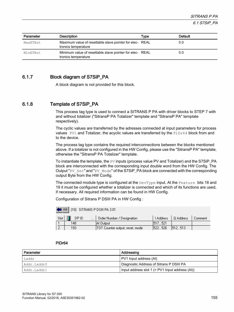
Parameter Description Type DefaultMaxETRst Maximum value of resettable slave pointer for elec‐
tronics temperatureREAL 0.0
MinETRst Minimum value of resettable slave pointer for elec‐tronics temperature
REAL 0.0
6.1.7 Block diagram of S7SiP_PAA block diagram is not provided for this block.
6.1.8 Template of S7SiP_PAThis process tag type is used to connect a SITRANS P PA with driver blocks to STEP 7 with and without totalizer ("SitransP PA Totalizer" template and "SitransP PA" template respectively).
The cyclic values are transferred by the adresses connected at input parameters for process values PV1 and Totalizer, the acyclic values are transferred by the PiDr64 block from and to the device.
The process tag type contains the required interconnections between the blocks mentioned above. If a totalizer is not configured in the HW Config, please use the "SitransP PA" template, otherwise the "SitransP PA Totalizer" template.
To instantiate the template, the PV inputs (process value PV and Totalizer) and the S7SiP_PA block are interconnected with the corresponding input double word from the HW Config. The Output "PV_Set" and "PV_Mode" of the S7SiP_PA block are connected with the corresponding output Byte from the HW Config.
The connected module type is configured at the DevType input. At the Feature bits 18 and 19 it must be configured whether a totalizer is connected and which of its functions are used, if necessary. All required information can be found in HW Config.
Configuration of Sitrans P DSIII PA in HW Config :
PiDr64
Parameter AddressingLaddr PV1 Input address (AI)Addr.Laddr0 Diagnostic Address of Sitrans P DSIII PAAddr.Laddr1 Input address slot 1 (= PV1 Input address (AI))
SITRANS P PA6.1 S7SiP_PA
SITRANS Library for S7-300Function Manual, 02/2018, A5E35351982-02 155
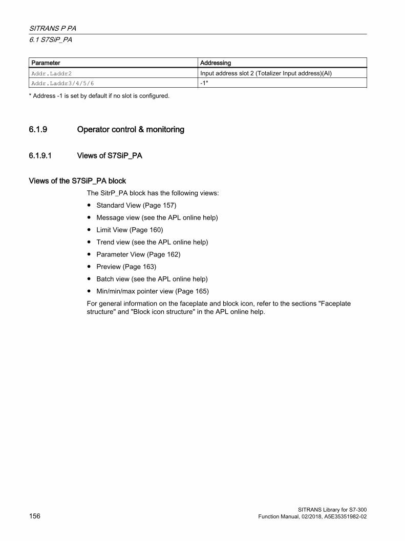
Parameter AddressingAddr.Laddr2 Input address slot 2 (Totalizer Input address)(AI)Addr.Laddr3/4/5/6 -1*
* Address -1 is set by default if no slot is configured.
6.1.9 Operator control & monitoring
6.1.9.1 Views of S7SiP_PA
Views of the S7SiP_PA blockThe SitrP_PA block has the following views:
● Standard View (Page 157)
● Message view (see the APL online help)
● Limit View (Page 160)
● Trend view (see the APL online help)
● Parameter View (Page 162)
● Preview (Page 163)
● Batch view (see the APL online help)
● Min/min/max pointer view (Page 165)
For general information on the faceplate and block icon, refer to the sections "Faceplate structure" and "Block icon structure" in the APL online help.
SITRANS P PA6.1 S7SiP_PA
SITRANS Library for S7-300156 Function Manual, 02/2018, A5E35351982-02

6.1.9.2 Standard view of S7SiP_PADepending on the configuration of the process value and the totalizer, the current process value for pressure, volume flow, mass flow, level, volume, pressure (untrimmed), sensor and electronics temperature, and the totalizer value are displayed. If a measured value is not assigned to a variable, the field is hidden. The gradient values always refer to the process value PV.
(1) Display and switch the operating modeThis area provides information on the currently valid operating mode. The operating mode switchover depends on whether or not a totalizer is configured.
Without totalizer:
The following operating modes can be shown here:
● On (see APL Online Help)
● Out of service (see APL Online Help)
With totalizer:
The block can be operated using the following modes:
● Local mode
● Automatic mode
● Manual mode
● Out of service
For more information on changing the operating mode, refer to the "Switching operating states and operating modes" section in the APL Online Help.
SITRANS P PA6.1 S7SiP_PA
SITRANS Library for S7-300Function Manual, 02/2018, A5E35351982-02 157

(2) Display and change the totalizer command: Positive and negative, positive, negative and holdThis area shows you the default operating state for the counters. The following states can be shown and executed here:
● "Positive and negative"
● "Positive"
● "Negative"
● "Hold"
If a totalizer is not configured, the area is switched to invisible.
(3) High and low scale range for the process value (PV)These values provide information on the display range for the bar graph of the process value PV. The scale range is set in the engineering system with the PV_OpScale parameter, see Display and operating range for process values and limits.
(4) Display of the process value (PV)This area indicates the current process value (PV). The name of the configured measured value is displayed depending on the PV_Meas variable, in this case "Pressure".
(5) High and low scale range for the gradient valueThese values provide information on the display range for the bar graph of the gradient. The scale range corresponds to 10% of the scale range for the process value (PV): If you have entered a scale range for the process value of 0 to 100, for example, the scale range for the gradient is automatically defined as -10 to 10.
The current gradient value is displayed if one of the monitoring functions is enabled:
● Gradient monitoring for positive changes (GradHUpEn = 1)
● Gradient monitoring for negative changes (GradHDnEn = 1)
● Gradient monitoring (GradLEn = 1)
(6) Display of gradientThis area shows the current, minimum and maximum gradient value of the process value PV as well as rising and falling of the value. This display of the minimum and maximum gradient value functions like a slave pointer.
The current gradient value is displayed if one of the monitoring functions is enabled:
● Gradient monitoring for positive changes (GradHUpEn = 1)
● Gradient monitoring for negative changes (GradHDnEn = 1)
● Gradient monitoring (GradLEn = 1)
The maximum peak gradient value is displayed if the gradient monitoring function for positive changes is enabled (GradHUpEn = 1)
SITRANS P PA6.1 S7SiP_PA
SITRANS Library for S7-300158 Function Manual, 02/2018, A5E35351982-02
The minimum peak gradient value is displayed if the gradient monitoring function for negative changes is enabled (GradHDnEn = 1)
(7) Resetting of peak values of the gradientUsing these buttons you can reset the maximum or minimum peak value of the gradient (output parameters PV_GradPP0 and PV_GradNP0).
The button is displayed if the gradient monitoring function for positive (GradHUpEn = 1) or negative changes (GradHDnEn = 1) is enabled.
(8) Display of the totalizer value This area shows the current totalizer value.
If a totalizer is not configured, the area is switched to invisible.
(9) Resetting the totalizer valueClick on this button to reset the totalizer value.
If a totalizer is not configured, the area is switched to invisible.
(10) and (12) Display area for block statesThis area provides additional information on the operating state of the block:
● "Invalid signal"/"Switchover error"
● "Wrong device"
(11) Display area for switch permissionThis area provides the text of the current OS, according to the enumeration configured at the PERMIS input.
(13) Bar graph for the "process value" (PV)This area shows the current "process value" (PV) in the form of a bar graph. The visible area in the bar graph depends on the configuration in the engineering system (ES), see Display and operating range for process values and limits.
(14) Limit displayThese small, colored triangles indicate the specified limits of the process value PV in the respective bar graph.
SITRANS P PA6.1 S7SiP_PA
SITRANS Library for S7-300Function Manual, 02/2018, A5E35351982-02 159
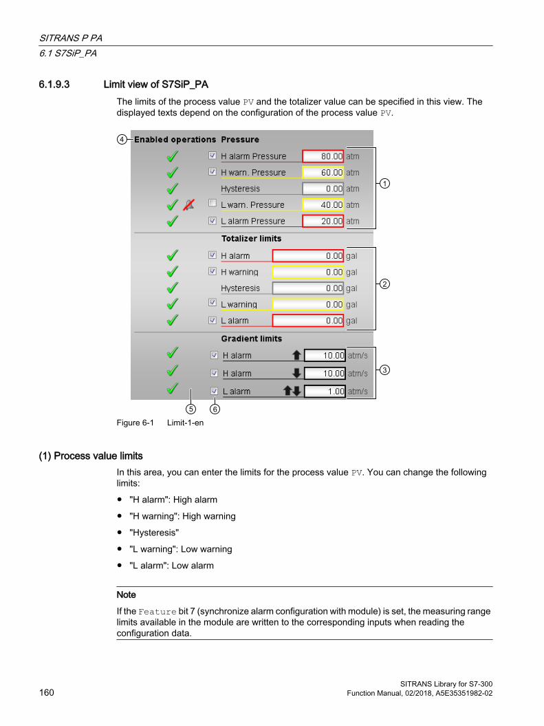
6.1.9.3 Limit view of S7SiP_PAThe limits of the process value PV and the totalizer value can be specified in this view. The displayed texts depend on the configuration of the process value PV.
Figure 6-1 Limit-1-en
(1) Process value limitsIn this area, you can enter the limits for the process value PV. You can change the following limits:
● "H alarm": High alarm
● "H warning": High warning
● "Hysteresis"
● "L warning": Low warning
● "L alarm": Low alarm
Note
If the Feature bit 7 (synchronize alarm configuration with module) is set, the measuring range limits available in the module are written to the corresponding inputs when reading the configuration data.
SITRANS P PA6.1 S7SiP_PA
SITRANS Library for S7-300160 Function Manual, 02/2018, A5E35351982-02
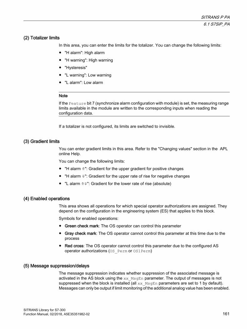
(2) Totalizer limitsIn this area, you can enter the limits for the totalizer. You can change the following limits:
● "H alarm": High alarm
● "H warning": High warning
● "Hysteresis"
● "L warning": Low warning
● "L alarm": Low alarm
Note
If the Feature bit 7 (synchronize alarm configuration with module) is set, the measuring range limits available in the module are written to the corresponding inputs when reading the configuration data.
If a totalizer is not configured, its limits are switched to invisible.
(3) Gradient limits You can enter gradient limits in this area. Refer to the "Changing values" section in the APL online Help.
You can change the following limits:
● "H alarm ⇑": Gradient for the upper gradient for positive changes
● "H alarm ⇓": Gradient for the upper rate of rise for negative changes
● "L alarm ⇑⇓": Gradient for the lower rate of rise (absolute)
(4) Enabled operationsThis area shows all operations for which special operator authorizations are assigned. They depend on the configuration in the engineering system (ES) that applies to this block.
Symbols for enabled operations:
● Green check mark: The OS operator can control this parameter
● Gray check mark: The OS operator cannot control this parameter at this time due to the process
● Red cross: The OS operator cannot control this parameter due to the configured AS operator authorizations (OS_Perm or OS1Perm)
(5) Message suppression/delaysThe message suppression indicates whether suppression of the associated message is activated in the AS block using the xx_MsgEn parameter. The output of messages is not suppressed when the block is installed (all xx_MsgEn parameters are set to 1 by default). Messages can only be output if limit monitoring of the additional analog value has been enabled.
SITRANS P PA6.1 S7SiP_PA
SITRANS Library for S7-300Function Manual, 02/2018, A5E35351982-02 161
Alarm delays are also displayed in this state; refer to the "Application of alarm delays" section in the APL Online Help.
(6) Suppress messagesYou can activate/deactivate messages by selecting the check mark.
6.1.9.4 Parameter view of S7SiP_PA
(1) Reading the configuration dataIn this area, you can read all configuration data relevant to the block from Sitrans P_PA.
(2) Writing the configuration dataIn this area, you can write all relevant configuration data, i.e. limits, to the Sitrans P_PA.
(3) Totalizer preset valueIn this area, you specify a preinstall value for the totalizer, and set the totalizer to this value with the click of a button.
If a totalizer is not configured, the area is switched to invisible.
(4) Sensor and electronics temperatureThe sensor and electronics temperature is displayed here. Both values are read either with a button click in the faceplate or cyclically (see TmpCycl input and Feature bit 6, including note).
SITRANS P PA6.1 S7SiP_PA
SITRANS Library for S7-300162 Function Manual, 02/2018, A5E35351982-02
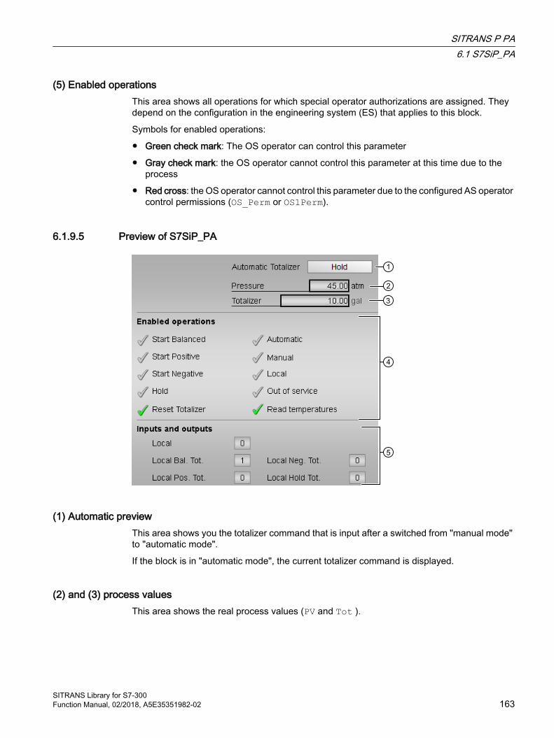
(5) Enabled operationsThis area shows all operations for which special operator authorizations are assigned. They depend on the configuration in the engineering system (ES) that applies to this block.
Symbols for enabled operations:
● Green check mark: The OS operator can control this parameter
● Gray check mark: the OS operator cannot control this parameter at this time due to the process
● Red cross: the OS operator cannot control this parameter due to the configured AS operator control permissions (OS_Perm or OS1Perm).
6.1.9.5 Preview of S7SiP_PA
(1) Automatic previewThis area shows you the totalizer command that is input after a switched from "manual mode" to "automatic mode".
If the block is in "automatic mode", the current totalizer command is displayed.
(2) and (3) process valuesThis area shows the real process values (PV and Tot ).
SITRANS P PA6.1 S7SiP_PA
SITRANS Library for S7-300Function Manual, 02/2018, A5E35351982-02 163
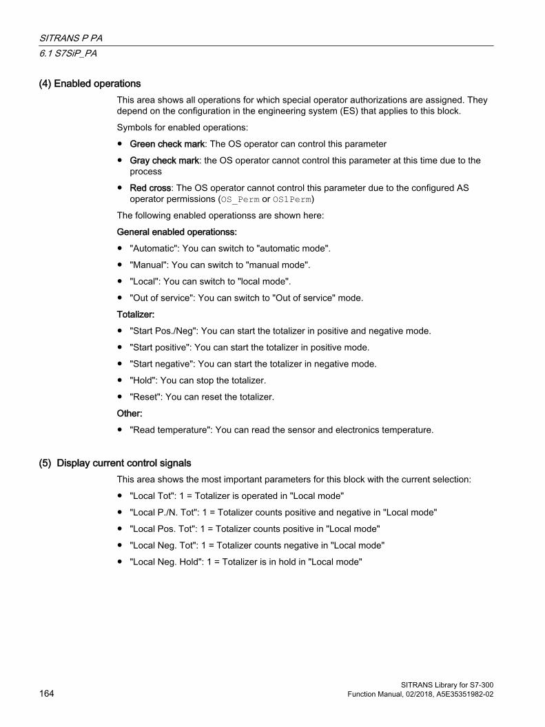
(4) Enabled operationsThis area shows all operations for which special operator authorizations are assigned. They depend on the configuration in the engineering system (ES) that applies to this block.
Symbols for enabled operations:
● Green check mark: The OS operator can control this parameter
● Gray check mark: the OS operator cannot control this parameter at this time due to the process
● Red cross: The OS operator cannot control this parameter due to the configured AS operator permissions (OS_Perm or OS1Perm)
The following enabled operationss are shown here:
General enabled operationss:
● "Automatic": You can switch to "automatic mode".
● "Manual": You can switch to "manual mode".
● "Local": You can switch to "local mode".
● "Out of service": You can switch to "Out of service" mode.
Totalizer:
● "Start Pos./Neg": You can start the totalizer in positive and negative mode.
● "Start positive": You can start the totalizer in positive mode.
● "Start negative": You can start the totalizer in negative mode.
● "Hold": You can stop the totalizer.
● "Reset": You can reset the totalizer.
Other:
● "Read temperature": You can read the sensor and electronics temperature.
(5) Display current control signalsThis area shows the most important parameters for this block with the current selection:
● "Local Tot": 1 = Totalizer is operated in "Local mode"
● "Local P./N. Tot": 1 = Totalizer counts positive and negative in "Local mode"
● "Local Pos. Tot": 1 = Totalizer counts positive in "Local mode"
● "Local Neg. Tot": 1 = Totalizer counts negative in "Local mode"
● "Local Neg. Hold": 1 = Totalizer is in hold in "Local mode"
SITRANS P PA6.1 S7SiP_PA
SITRANS Library for S7-300164 Function Manual, 02/2018, A5E35351982-02
6.1.9.6 Min/min/max pointer view of S7SiP_PA (resettable)
(1) Display and reset resettable slave pointerThe last values of the resettable min/max pointer read from the device are shown in this area, and reset if applicable. Min/max pointers which are not available in the device are not displayed.
● Maximum value slave pointer for pressure
● Minimum value resettable slave pointer for pressure
● Maximum value slave pointer for sensor temperature
● Minimum value slave pointer for sensor temperature
● Maximum value slave pointer for electronics temperature
● Minimum value slave pointer for electronics temperature
(2) Read out min/max pointersIn this area, you can read out the values of all slave pointers from the module.
(3) Enabled operationsThis area shows all operations for which special operator authorizations are assigned. They depend on the configuration in the engineering system (ES) that applies to this block.
SITRANS P PA6.1 S7SiP_PA
SITRANS Library for S7-300Function Manual, 02/2018, A5E35351982-02 165

Symbols for enabled operations:
● Green check mark: The OS operator can control this parameter
● Gray check mark: the OS operator cannot control this parameter at this time due to the process
● Red cross: The OS operator cannot control this parameter due to the configured AS operator permissions (OS_Perm or OS1Perm)
6.1.9.7 Block icon for S7SiP_PAA variety of block icons is available with the following functions:
● Process tag type
● Limits (high/low)
● Violation of alarm and warning limits as well as the control system fault CSF● Operating modes
● Process value (PV)
The block icons from template @TemplateAPL_SITRANS.PDL:
Icons Selection of the block icon in CFC Special features1 Only PV is used
- Block icon in the "Out of service" operating mode
Process value and totalizer are used
For more information on the block icon and operating options in the block icon, refer to the following sections in the APL online help:
● "Configuring the block icons"
● "Block icon structure"
● "Operation via the block icon"
SITRANS P PA6.1 S7SiP_PA
SITRANS Library for S7-300166 Function Manual, 02/2018, A5E35351982-02
SITRANS P 77.1 S7SitPHA
7.1.1 Description of S7SitPHA
Object name (type + number) and family Type + number: FB 2635
Family: Sitrans
Area of application of S7SitPHA The block is used for the following applications:
● Interface block between the driver blocks of the SITRANS P300/P500/DSIII modules (referred to below as SITRANS P) for the user program and visualization
How it works The S7SiPHA block prepares the process data received from driver blocks from a SITRANS P and makes the data available for further use in the user program and for visualization. Data entered in the faceplate or via the block inputs is transferred to the SITRANS P by means of driver blocks.
The function block supports display of the 4 to 20 mA signal, the HART variables and the slave pointer according to the configuration of the S7SiPHA. The 4 to 20 mA signal, and not the first HART auxiliary variable PV, is always used as the process value if both contain the same physical variable.
Configuration Use the CFC-Editor to install the block in a cyclic interrupt OB (OB30 to OB38). The block is also installed automatically in the startup OB (OB100). Moreover, to connect the I/O signals, it is imperative to call the driver blocks SCALE (cyclic data, 4 to 20 mA) and PiDr64 (acyclic data) in the same interrupt OB and startup OB (OB100) before the S7SitPHA block in each case. The output structure AcyclData of the PiDr64 block is interconnected to the input with the same name of the S7SitPHA block.
The SlotHart input receives the slot number of the S7SitPHA within the analog input module. The Feature bits 2 to 6 must be used to configure whether communication with the module is by means of the HART protocol and, if applicable, which HART variables are used. Feature bit 7 = TRUE means that the block takes over the alarm configuration including limits when reading the configuration data from the device. If HART communication is used, reading out of the module configuration can be triggered in the WinCC faceplate. Otherwise, the
SITRANS Library for S7-300Function Manual, 02/2018, A5E35351982-02 167
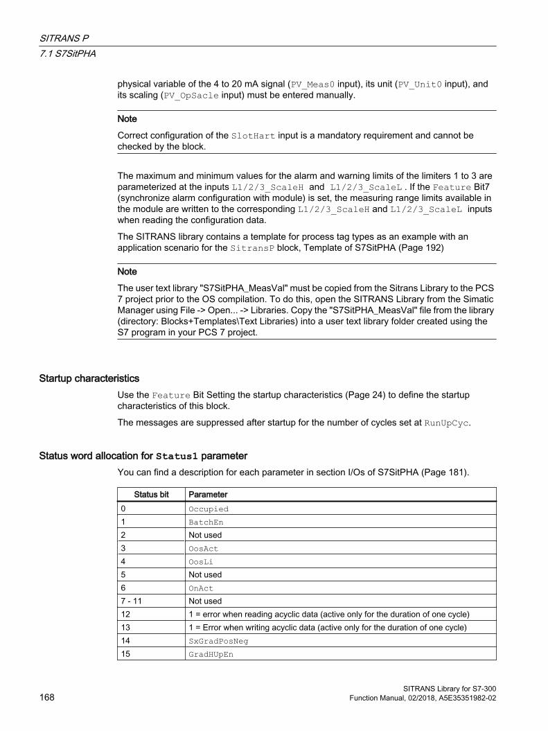
physical variable of the 4 to 20 mA signal (PV_Meas0 input), its unit (PV_Unit0 input), and its scaling (PV_OpSacle input) must be entered manually.
Note
Correct configuration of the SlotHart input is a mandatory requirement and cannot be checked by the block.
The maximum and minimum values for the alarm and warning limits of the limiters 1 to 3 are parameterized at the inputs L1/2/3_ScaleH and L1/2/3_ScaleL . If the Feature Bit7 (synchronize alarm configuration with module) is set, the measuring range limits available in the module are written to the corresponding L1/2/3_ScaleH and L1/2/3_ScaleL inputs when reading the configuration data.
The SITRANS library contains a template for process tag types as an example with an application scenario for the SitransP block, Template of S7SitPHA (Page 192)
Note
The user text library "S7SitPHA_MeasVal" must be copied from the Sitrans Library to the PCS 7 project prior to the OS compilation. To do this, open the SITRANS Library from the Simatic Manager using File -> Open... -> Libraries. Copy the "S7SitPHA_MeasVal" file from the library (directory: Blocks+Templates\Text Libraries) into a user text library folder created using the S7 program in your PCS 7 project.
Startup characteristics Use the Feature Bit Setting the startup characteristics (Page 24) to define the startup characteristics of this block.
The messages are suppressed after startup for the number of cycles set at RunUpCyc.
Status word allocation for Status1 parameter You can find a description for each parameter in section I/Os of S7SitPHA (Page 181).
Status bit Parameter0 Occupied1 BatchEn2 Not used3 OosAct4 OosLi5 Not used6 OnAct7 - 11 Not used12 1 = error when reading acyclic data (active only for the duration of one cycle)13 1 = Error when writing acyclic data (active only for the duration of one cycle)14 SxGradPosNeg15 GradHUpEn
SITRANS P7.1 S7SitPHA
SITRANS Library for S7-300168 Function Manual, 02/2018, A5E35351982-02
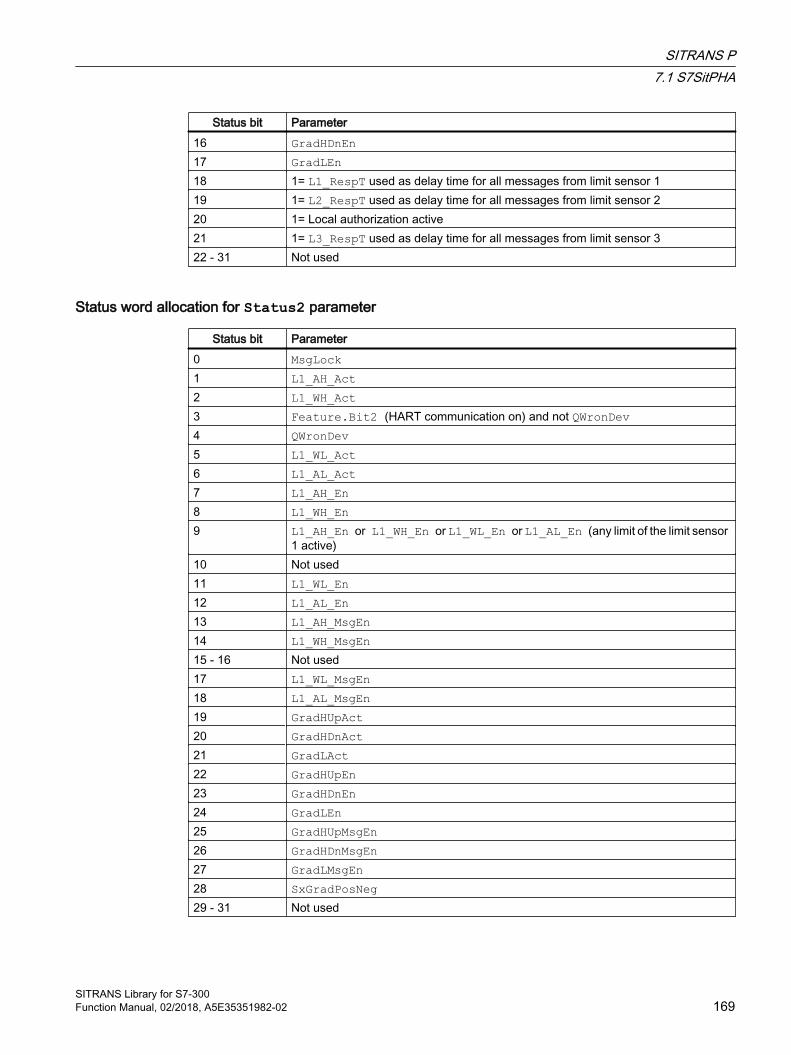
Status bit Parameter16 GradHDnEn17 GradLEn18 1= L1_RespT used as delay time for all messages from limit sensor 119 1= L2_RespT used as delay time for all messages from limit sensor 220 1= Local authorization active21 1= L3_RespT used as delay time for all messages from limit sensor 322 - 31 Not used
Status word allocation for Status2 parameter
Status bit Parameter0 MsgLock1 L1_AH_Act2 L1_WH_Act3 Feature.Bit2 (HART communication on) and not QWronDev4 QWronDev5 L1_WL_Act6 L1_AL_Act7 L1_AH_En8 L1_WH_En9 L1_AH_En or L1_WH_En or L1_WL_En or L1_AL_En (any limit of the limit sensor
1 active)10 Not used11 L1_WL_En12 L1_AL_En13 L1_AH_MsgEn14 L1_WH_MsgEn15 - 16 Not used17 L1_WL_MsgEn18 L1_AL_MsgEn19 GradHUpAct20 GradHDnAct21 GradLAct22 GradHUpEn23 GradHDnEn24 GradLEn25 GradHUpMsgEn26 GradHDnMsgEn27 GradLMsgEn28 SxGradPosNeg29 - 31 Not used
SITRANS P7.1 S7SitPHA
SITRANS Library for S7-300Function Manual, 02/2018, A5E35351982-02 169
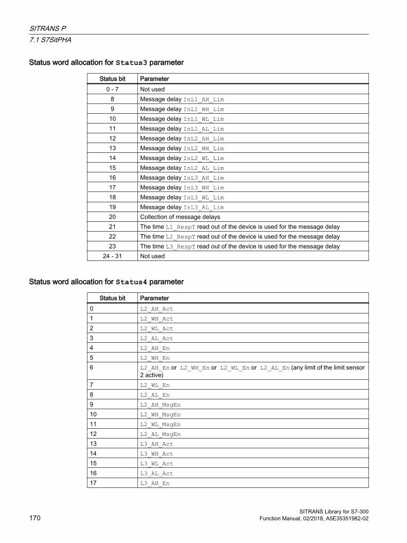
Status word allocation for Status3 parameter
Status bit Parameter0 - 7 Not used
8 Message delay InL1_AH_Lim9 Message delay InL1_WH_Lim10 Message delay InL1_WL_Lim11 Message delay InL1_AL_Lim12 Message delay InL2_AH_Lim13 Message delay InL2_WH_Lim14 Message delay InL2_WL_Lim15 Message delay InL2_AL_Lim16 Message delay InL3_AH_Lim17 Message delay InL3_WH_Lim18 Message delay InL3_WL_Lim19 Message delay InL3_AL_Lim20 Collection of message delays21 The time L1_RespT read out of the device is used for the message delay22 The time L2_RespT read out of the device is used for the message delay23 The time L3_RespT read out of the device is used for the message delay
24 - 31 Not used
Status word allocation for Status4 parameter
Status bit Parameter0 L2_AH_Act1 L2_WH_Act2 L2_WL_Act3 L2_AL_Act4 L2_AH_En5 L2_WH_En6 L2_AH_En or L2_WH_En or L2_WL_En or L2_AL_En (any limit of the limit sensor
2 active)7 L2_WL_En8 L2_AL_En9 L2_AH_MsgEn10 L2_WH_MsgEn11 L2_WL_MsgEn12 L2_AL_MsgEn13 L3_AH_Act14 L3_WH_Act15 L3_WL_Act16 L3_AL_Act17 L3_AH_En
SITRANS P7.1 S7SitPHA
SITRANS Library for S7-300170 Function Manual, 02/2018, A5E35351982-02

Status bit Parameter18 L3_WH_En19 L3_AH_En or L3_WH_En or L3_WL_En or L3_AL_En (any limit of the limit sensor 3
active)20 L3_WL_En21 L3_AL_En22 L3_AH_MsgEn23 L3_WH_MsgEn24 L3_WL_MsgEn25 L3_AL_MsgEn26 Connected device is a SITRANS P50027 Alarm limit (high) for PV_In (4 to 20 mA signal) (PV_In) active28 Warning limit (high) for PV_In (4 to 20 mA signal) active29 Warning limit (low) for PV_In (4 to 20 mA signal) active30 Alarm limit (low) for PV_In (4 to 20 mA signal) active31 Not used
7.1.2 Operating modes of S7SitPHAThe block can be operated using the following modes:
● On
● Out of service
"On"
You can find general information about the "On" mode in the On chapter.
"Out of service"
You can find general information about the "Out of service" mode in the Out of service section.
The descriptions of the operating modes are identical for SitransP and the APL; refer to the online help for the standard APL blocks for information on them.
7.1.3 Functions of S7SitPHAThe functions for this block are listed below.
Configuration data The configuration data comprises units, configuration of the 4 to 20 mA signal and HART variables, and scaling of the 4 to 20 mA signal. After a change is made in the device, reading of configuration data must be triggered with "Read configuration data" in the parameter view of the faceplate. If the parameters were read back before a complete download to the PLC, the configuration does not need to be reloaded from the device.
SITRANS P7.1 S7SitPHA
SITRANS Library for S7-300Function Manual, 02/2018, A5E35351982-02 171

The message limits of the SitransP are only transferred to the device if HART communication is used (Feature Bit2 = TRUE) and the alarm configuration is synchronized with the device (Feature Bit7 = TRUE).
The S7SitPHA function block has the following configuration data which can be read out of the SitransP by means of the "Read configuration data" command:
Description Block parameters (I/O) Read com‐mandP500
Read com‐mandP300/DSIII
Units of 4 to 20 mA signal and HART variables
PV_Unit0/PV_InUnitPV_Unit1/---PV_Unit2/---PV_Unit3/---PV_Unit4/---
3/50 3/50
Unit of user value as string UsrUnitS 132 176Scaling of 4 to 20 mA signal ScaleInL/ScaleOutL
ScaleInH/ScaleOutH15 15
Limits/parameter assignment Limit sensor x(x=1/2/3)
InLx_AH_Lim/Lx_AH_LimInLx_WH_Lim/Lx_WH_LimInLx_WL_Lim/Lx_WL_LimInLx_AL_Lim/Lx_AL_LimInLx_Hyst/Lx_HystInLx_RespT/Lx_RespTInLx_Unit/---InLx_DevVar/---Lx_AlmAct/---Lx_MonAct/---Lx_MonTrig/---Lx_AH/WH/WL/AL_En/---Lx_AH/WH/WL/AL_MsgEn/---
169 178
Slave pointer(resettable/not resettable)
MaxPRst/MinPRstMaxSPRst/MinSPRst MaxSTRst/MinSTRst MaxETRst/MinETRst
172 162
Minimum and maximum limit values(x=1/2/3)
Lx_ScaleH/L 15 15/ 170/ 172
When writing the configuration data, only the limits of the limit sensors are transferred to the module in accordance with their configuration (Lx_MonAct, Lx_MonTrig), but not the configuration itself.
Note
If the module is used without HART communication, the inputs must be parameterized accordingly manually since reading out of the configuration from the module is not possible.
Note
If alarm or warning limits are deactivated in the module by means of PDM, these are set to the corresponding active warning or alarm limits or to the maximum or minimum value of the limit sensor (L1/2/3_ScaleH/L) for consistency reasons when loading modified active alarm or warning limits or the hysteresis value.
SITRANS P7.1 S7SitPHA
SITRANS Library for S7-300172 Function Manual, 02/2018, A5E35351982-02
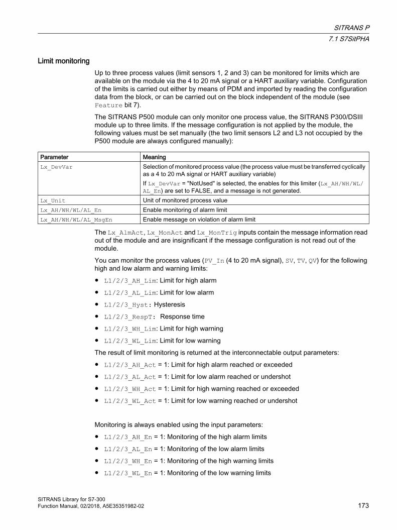
Limit monitoringUp to three process values (limit sensors 1, 2 and 3) can be monitored for limits which are available on the module via the 4 to 20 mA signal or a HART auxiliary variable. Configuration of the limits is carried out either by means of PDM and imported by reading the configuration data from the block, or can be carried out on the block independent of the module (see Feature bit 7).
The SITRANS P500 module can only monitor one process value, the SITRANS P300/DSIII module up to three limits. If the message configuration is not applied by the module, the following values must be set manually (the two limit sensors L2 and L3 not occupied by the P500 module are always configured manually):
Parameter MeaningLx_DevVar Selection of monitored process value (the process value must be transferred cyclically
as a 4 to 20 mA signal or HART auxiliary variable)If Lx_DevVar = "NotUsed" is selected, the enables for this limiter (Lx_AH/WH/WL/AL_En) are set to FALSE, and a message is not generated.
Lx_Unit Unit of monitored process valueLx_AH/WH/WL/AL_En Enable monitoring of alarm limitLx_AH/WH/WL/AL_MsgEn Enable message on violation of alarm limit
The Lx_AlmAct, Lx_MonAct and Lx_MonTrig inputs contain the message information read out of the module and are insignificant if the message configuration is not read out of the module.
You can monitor the process values (PV_In (4 to 20 mA signal), SV, TV, QV) for the following high and low alarm and warning limits:
● L1/2/3_AH_Lim: Limit for high alarm
● L1/2/3_AL_Lim: Limit for low alarm
● L1/2/3_Hyst: Hysteresis
● L1/2/3_RespT: Response time
● L1/2/3_WH_Lim: Limit for high warning
● L1/2/3_WL_Lim: Limit for low warning
The result of limit monitoring is returned at the interconnectable output parameters:
● L1/2/3_AH_Act = 1: Limit for high alarm reached or exceeded
● L1/2/3_AL_Act = 1: Limit for low alarm reached or undershot
● L1/2/3_WH_Act = 1: Limit for high warning reached or exceeded
● L1/2/3_WL_Act = 1: Limit for low warning reached or undershot
Monitoring is always enabled using the input parameters:
● L1/2/3_AH_En = 1: Monitoring of the high alarm limits
● L1/2/3_AL_En = 1: Monitoring of the low alarm limits
● L1/2/3_WH_En = 1: Monitoring of the high warning limits
● L1/2/3_WL_En = 1: Monitoring of the low warning limits
SITRANS P7.1 S7SitPHA
SITRANS Library for S7-300Function Manual, 02/2018, A5E35351982-02 173

The corresponding message is suppressed using the parameters:
● L1/2/3_AH_MsgEn = 0: Alarm (high) messages are suppressed
● L1/2/3_AL_MsgEn = 0: Alarm (low) messages are suppressed
● L1/2/3_WH_MsgEn = 0: Warning (high) messages are suppressed
● L1/2/3_WL_MsgEn = 0: Warning (low) messages are suppressed
You can define a hysteresis (L1/2/3_Hyst) and a response time (L1/2/3_RespT) for the limits, for example to suppress signal flatter. You can also modify the limits, the hysteresis and the response time via the faceplate.
Gradient monitoringThe gradient PV_Grad0 is calculated by means of a delay function configurable using LagTime. During calculation of the gradient, jumps in the input value PV_In are smoothed.
The peak values of the gradient are output in the output parameters PV_GradNP0 (negative gradient) and PV_GradPP0 (positive gradient). These are reset when the operator enters the corresponding command for resetting.
The slope of the gradient PV_Grad can be monitored for the following limits:
● Limit (high) for the positive gradient (GradHUpLim)
● Limit (high) for the negative gradient (GradHDnLim)
● Limit (low) for the absolute gradient (GradLLim)
Activation of the individual monitoring functions is carried out at the corresponding "Enable" parameters, e.g. GradHUpEn for activating the high gradient limit for positive gradients (GradHUpLim).
Reaching or violation of your defined limits is indicated at the corresponding "Active" output parameters, e.g. by means of GradHUpAct = 1 for the limit (high) for the positive gradient.
Messages can be output for these alarms. You can activate these as follows:
● Message for alarms (high) for the positive gradient: GradHUpMsgEn = 1
● Message for alarms (high) for the negative gradient: GradHDnMsgEn = 1
● Message for alarms (low) for the absolute gradient: GradLMsgEn = 1
Suppressing messages using the MsgLock parameterThis block provides the standard "Suppressing messages using the MsgLock parameter" function that is described in the APL Online Help.
Selecting a unit of measureThe units for the 4 to 20 mA signal and the HART variables are configured on the device of the HART via PDM and read by an operator action in the "Parameters" faceplate view with "Read configuration" or configured by the user himself if SITRANS P communication does not exist.
SITRANS P7.1 S7SitPHA
SITRANS Library for S7-300174 Function Manual, 02/2018, A5E35351982-02
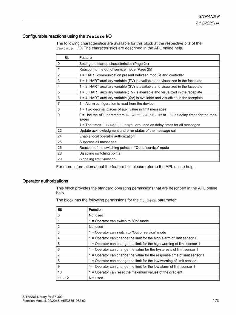
Configurable reactions using the Feature I/OThe following characteristics are available for this block at the respective bits of the Feature I/O. The characteristics are described in the APL online help.
Bit Feature0 Setting the startup characteristics (Page 24)1 Reaction to the out of service mode (Page 25)2 1 = HART communication present between module and controller3 1 = 1. HART auxiliary variable (PV) is available and visualized in the faceplate4 1 = 2. HART auxiliary variable (SV) is available and visualized in the faceplate5 1 = 3. HART auxiliary variable (TV) is available and visualized in the faceplate6 1 = 4. HART auxiliary variable (QV) is available and visualized in the faceplate7 1 = Alarm configuration is read from the device8 1 = Two decimal places of aux. value in limit messages9 0 = Use the APL parameters Lx_AH/WH/WL/AL_DC or _DG as delay times for the mes‐
sages1 = The times L1/L2/L3_RespT are used as delay times for all messages
22 Update acknowledgment and error status of the message call24 Enable local operator authorization25 Suppress all messages26 Reaction of the switching points in "Out of service" mode 28 Disabling switching points29 Signaling limit violation
For more information about the feature bits please refer to the APL online help.
Operator authorizationsThis block provides the standard operating permissions that are described in the APL online help.
The block has the following permissions for the OS_Perm parameter:
Bit Function0 Not used1 1 = Operator can switch to "On" mode2 Not used3 1 = Operator can switch to "Out of service" mode4 1 = Operator can change the limit for the high alarm of limit sensor 15 1 = Operator can change the limit for the high warning of limit sensor 16 1 = Operator can change the value for the hysteresis of limit sensor 17 1 = Operator can change the value for the response time of limit sensor 18 1 = Operator can change the limit for the low warning of limit sensor 19 1 = Operator can change the limit for the low alarm of limit sensor 110 1 = Operator can reset the maximum values of the gradient11 - 12 Not used
SITRANS P7.1 S7SitPHA
SITRANS Library for S7-300Function Manual, 02/2018, A5E35351982-02 175
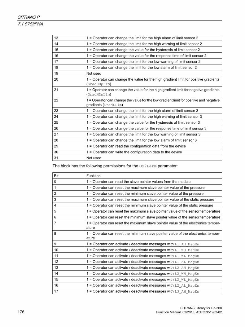
13 1 = Operator can change the limit for the high alarm of limit sensor 214 1 = Operator can change the limit for the high warning of limit sensor 215 1 = Operator can change the value for the hysteresis of limit sensor 216 1 = Operator can change the value for the response time of limit sensor 217 1 = Operator can change the limit for the low warning of limit sensor 218 1 = Operator can change the limit for the low alarm of limit sensor 219 Not used20 1 = Operator can change the value for the high gradient limit for positive gradients
(GradHUpLim)21 1 = Operator can change the value for the high gradient limit for negative gradients
(GradHDnLim)22 1 = Operator can change the value for the low gradient limit for positive and negative
gradients (GradLLim)23 1 = Operator can change the limit for the high alarm of limit sensor 324 1 = Operator can change the limit for the high warning of limit sensor 325 1 = Operator can change the value for the hysteresis of limit sensor 326 1 = Operator can change the value for the response time of limit sensor 327 1 = Operator can change the limit for the low warning of limit sensor 328 1 = Operator can change the limit for the low alarm of limit sensor 329 1 = Operator can read the configuration data from the device30 1 = Operator can write the configuration data to the device31 Not used
The block has the following permissions for the OS2Perm parameter:
Bit Funktion0 1 = Operator can read the slave pointer values from the module1 1 = Operator can reset the maximum slave pointer value of the pressure2 1 = Operator can reset the minimum slave pointer value of the pressure3 1 = Operator can reset the maximum slave pointer value of the static pressure4 1 = Operator can reset the minimum slave pointer value of the static pressure5 1 = Operator can reset the maximum slave pointer value of the sensor temperature6 1 = Operator can reset the minimum slave pointer value of the sensor temperature7 1 = Operator can reset the maximum slave pointer value of the electronics temper‐
ature8 1 = Operator can reset the minimum slave pointer value of the electronics temper‐
ature9 1 = Operator can activate / deactivate messages with L1_AH_MsgEn10 1 = Operator can activate / deactivate messages with L1_WH_MsgEn11 1 = Operator can activate / deactivate messages with L1_WL_MsgEn12 1 = Operator can activate / deactivate messages with L1_AL_MsgEn13 1 = Operator can activate / deactivate messages with L2_AH_MsgEn14 1 = Operator can activate / deactivate messages with L2_WH_MsgEn15 1 = Operator can activate / deactivate messages with L2_WL_MsgEn16 1 = Operator can activate / deactivate messages with L2_AL_MsgEn17 1 = Operator can activate / deactivate messages with L3_AH_MsgEn
SITRANS P7.1 S7SitPHA
SITRANS Library for S7-300176 Function Manual, 02/2018, A5E35351982-02
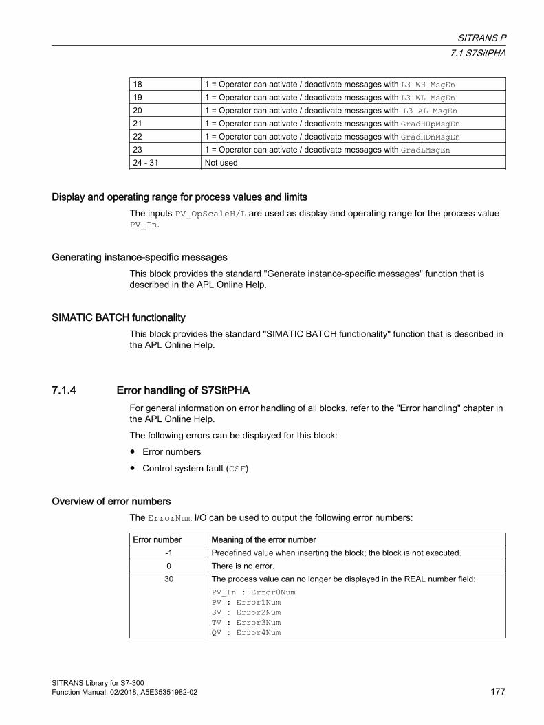
18 1 = Operator can activate / deactivate messages with L3_WH_MsgEn19 1 = Operator can activate / deactivate messages with L3_WL_MsgEn20 1 = Operator can activate / deactivate messages with L3_AL_MsgEn21 1 = Operator can activate / deactivate messages with GradHUpMsgEn22 1 = Operator can activate / deactivate messages with GradHDnMsgEn23 1 = Operator can activate / deactivate messages with GradLMsgEn24 - 31 Not used
Display and operating range for process values and limitsThe inputs PV_OpScaleH/L are used as display and operating range for the process value PV_In.
Generating instance-specific messagesThis block provides the standard "Generate instance-specific messages" function that is described in the APL Online Help.
SIMATIC BATCH functionalityThis block provides the standard "SIMATIC BATCH functionality" function that is described in the APL Online Help.
7.1.4 Error handling of S7SitPHAFor general information on error handling of all blocks, refer to the "Error handling" chapter in the APL Online Help.
The following errors can be displayed for this block:
● Error numbers
● Control system fault (CSF)
Overview of error numbersThe ErrorNum I/O can be used to output the following error numbers:
Error number Meaning of the error number-1 Predefined value when inserting the block; the block is not executed.0 There is no error.30 The process value can no longer be displayed in the REAL number field:
PV_In : Error0NumPV : Error1NumSV : Error2NumTV : Error3NumQV : Error4Num
SITRANS P7.1 S7SitPHA
SITRANS Library for S7-300Function Manual, 02/2018, A5E35351982-02 177
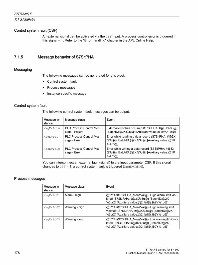
Control system fault (CSF)An external signal can be activated via the CSF input. A process control error is triggered if this signal = 1. Refer to the "Error handling" chapter in the APL Online Help.
7.1.5 Message behavior of S7SitPHA
Messaging The following messages can be generated for this block:
● Control system fault
● Process messages
● Instance-specific message
Control system fault The following control system fault messages can be output:
Message in‐stance
Message class Event
MsgEvId16 PLC Process Control Mes‐sage - Failure
External error has occurred (S7SitPHA: #@3X%3u@) [BatchID:@2X%3u@] [Auxiliary value:@1R%4.1f@]
MsgEvId17 PLC Process Control Mes‐sage - Error
Error while reading a data record (S7SitPHA: #@3X%3u@) [BatchID:@2X%3u@] [Auxiliary value:@1R%4.1f@]
MsgEvId18 PLC Process Control Mes‐sage - Error
Error while writing a data record (S7SitPHA: #@3X%3u@) [BatchID:@2X%3u@] [Auxiliary value:@1R%4.1f@]
You can interconnect an external fault (signal) to the input parameter CSF. If this signal changes to CSF = 1, a control system fault is triggered (MsgEvId16).
Process messages
Message in‐stance
Message class Event
MsgEvId01 Alarm - high @1Y%t#S7SitPHA_MeasVal@ - High alarm limit vio‐lated (S7SiLRHA: #@3X%3u@) [BatchID:@2X%3u@] [Auxiliary value:@2I%d@.@2Y%1u@]
MsgEvId02 Warning - high @1Y%t#S7SitPHA_MeasVal@ - High warning limit violated (S7SiLRHA: #@3X%3u@) [BatchID:@2X%3u@] [Auxiliary value:@2I%d@.@2Y%1u@]
MsgEvId03 Warning - low @1Y%t#S7SitPHA_MeasVal@ - Low warning limit vio‐lated (S7SiLRHA: #@3X%3u@) [BatchID:@2X%3u@] [Auxiliary value:@2I%d@.@2Y%1u@]
SITRANS P7.1 S7SitPHA
SITRANS Library for S7-300178 Function Manual, 02/2018, A5E35351982-02

MsgEvId04 Alarm - low @1Y%t#S7SitPHA_MeasVal@ - Low alarm limit viola‐ted (S7SiLRHA: #@3X%3u@) [BatchID:@2X%3u@] [Auxiliary value:@2I%d@.@2Y%1u@]
MsgEvId05 Alarm - high @1Y%t#S7SitPHA_MeasVal@ - High alarm limit vio‐lated (S7SiLRHA: #@3X%3u@) [BatchID:@2X%3u@] [Auxiliary value:@2I%d@.@2Y%1u@]
MsgEvId06 Warning - high @1Y%t#S7SitPHA_MeasVal@ - High warning limit violated (S7SiLRHA: #@3X%3u@) [BatchID:@2X%3u@] [Auxiliary value:@2I%d@.@2Y%1u@]
MsgEvId07 Warning - low @1Y%t#S7SitPHA_MeasVal@ - Low warning limit vio‐lated (S7SiLRHA: #@3X%3u@) [BatchID:@2X%3u@] [Auxiliary value:@2I%d@.@2Y%1u@]
MsgEvId08 Alarm - low @1Y%t#S7SitPHA_MeasVal@ - Low alarm limit viola‐ted (S7SiLRHA: #@3X%3u@) [BatchID:@2X%3u@] [Auxiliary value:@2I%d@.@2Y%1u@]
MsgEvId09 Alarm - high @1Y%t#S7SitPHA_MeasVal@ - High alarm limit vio‐lated (S7SiLRHA: #@3X%3u@) [BatchID:@2X%3u@] [Auxiliary value:@2I%d@.@2Y%1u@]
MsgEvId10 Warning - high @1Y%t#S7SitPHA_MeasVal@ - High warning limit violated (S7SiLRHA: #@3X%3u@) [BatchID:@2X%3u@] [Auxiliary value:@2I%d@.@2Y%1u@]
MsgEvId11 Warning - low @1Y%t#S7SitPHA_MeasVal@ - Low warning limit vio‐lated (S7SiLRHA: #@3X%3u@) [BatchID:@2X%3u@] [Auxiliary value:@2I%d@.@2Y%1u@]
MsgEvId12 Alarm - low @1Y%t#S7SitPHA_MeasVal@ - Low alarm limit viola‐ted (S7SiLRHA: #@3X%3u@) [BatchID:@2X%3u@] [Auxiliary value:@2I%d@.@2Y%1u@]
MsgEvId13 Alarm - high Limit value (high) for the positive gradient violated (S7SitPHA: #@3X%3u@) [BatchID:@2X%3u@] [Aux‐iliary value:@1R%4.1f@]
MsgEvId14 Alarm - high Limit value (high) for the negative gradient violated (S7SitPHA: #@3X%3u@) [BatchID:@2X%3u@] [Aux‐iliary value:@1R%4.1f@]
MsgEvId15 Alarm - low Limit value (low) for absolute gradient violated (S7Sit‐PHA: #@3X%3u@) [BatchID:@2X%3u@] [Auxiliary value:@1R%4.1f@]
Instance-specific message You can use one instance-specific message with this block.
Message in‐stance
Message class Event
MsgEvId19 PLC Process Control Mes‐sage - Failure
External message (S7SitPHA: #@3X%3u@) [Batch‐ID:@2X%3u@] [Auxiliary value:@1R%4.1f@]
SITRANS P7.1 S7SitPHA
SITRANS Library for S7-300Function Manual, 02/2018, A5E35351982-02 179

Associated values for message instances with limit violation
Associated value Block parameter Data Type1 PV_Meas0 BYTE2 AuxByte (one or two digits after
the decimal point, see Fea‐ture.Bit3)
BYTE
3 AuxWord (number before the decimal point: -32768 .. 32767)
WORD
4 BatchID DWORD5 MsgFilter DINT
Associated values for message instances without limit violation
Associated value Block parameter Data Type1 Aux REAL2 BatchID DWORD3 MsgFilter DINT
Message texts and their text numbers The following table shows the message texts and their numbers in the text library "S7SitPHA_MeasVal" for the S7SitPHA block (FB 2635):
Text number Message text0 Pressure1 Sensor temperature2 Electronics temperature3 Pressure4 Level5 Volume6 Mass7 Volume flow8 Mass flow9 User value10 Static pressure
SITRANS P7.1 S7SitPHA
SITRANS Library for S7-300180 Function Manual, 02/2018, A5E35351982-02
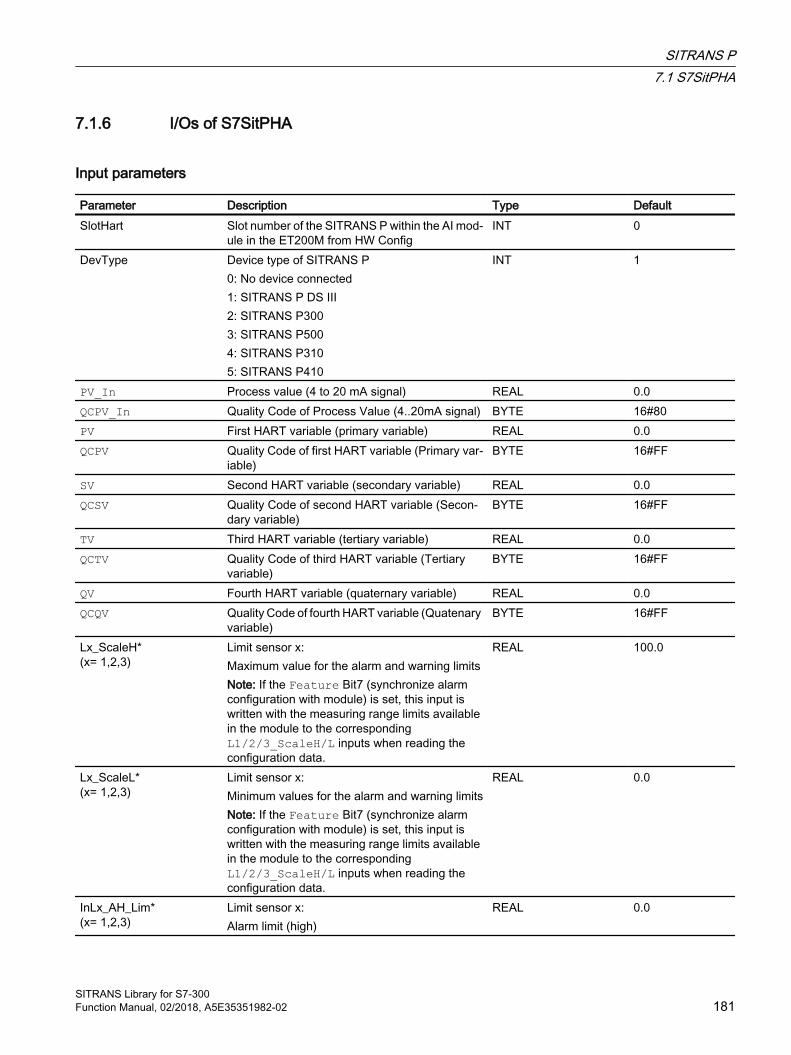
7.1.6 I/Os of S7SitPHA
Input parameters
Parameter Description Type DefaultSlotHart Slot number of the SITRANS P within the AI mod‐
ule in the ET200M from HW ConfigINT 0
DevType Device type of SITRANS P0: No device connected1: SITRANS P DS III2: SITRANS P3003: SITRANS P5004: SITRANS P3105: SITRANS P410
INT 1
PV_In Process value (4 to 20 mA signal) REAL 0.0QCPV_In Quality Code of Process Value (4..20mA signal) BYTE 16#80PV First HART variable (primary variable) REAL 0.0QCPV Quality Code of first HART variable (Primary var‐
iable)BYTE 16#FF
SV Second HART variable (secondary variable) REAL 0.0QCSV Quality Code of second HART variable (Secon‐
dary variable)BYTE 16#FF
TV Third HART variable (tertiary variable) REAL 0.0QCTV Quality Code of third HART variable (Tertiary
variable)BYTE 16#FF
QV Fourth HART variable (quaternary variable) REAL 0.0QCQV Quality Code of fourth HART variable (Quatenary
variable)BYTE 16#FF
Lx_ScaleH*(x= 1,2,3)
Limit sensor x:Maximum value for the alarm and warning limitsNote: If the Feature Bit7 (synchronize alarm configuration with module) is set, this input is written with the measuring range limits available in the module to the corresponding L1/2/3_ScaleH/L inputs when reading the configuration data.
REAL 100.0
Lx_ScaleL*(x= 1,2,3)
Limit sensor x:Minimum values for the alarm and warning limitsNote: If the Feature Bit7 (synchronize alarm configuration with module) is set, this input is written with the measuring range limits available in the module to the corresponding L1/2/3_ScaleH/L inputs when reading the configuration data.
REAL 0.0
InLx_AH_Lim*(x= 1,2,3)
Limit sensor x:Alarm limit (high)
REAL 0.0
SITRANS P7.1 S7SitPHA
SITRANS Library for S7-300Function Manual, 02/2018, A5E35351982-02 181

Parameter Description Type DefaultInLx_WH_Lim*(x= 1,2,3)
Limit sensor x:Warning limit (high)
REAL 0.0
InLx_Hyst*(x= 1,2,3)
Limit sensor x:Hysteresis for alarm and warning limits
REAL 0.0
InLx_RespT*(x= 1,2,3)
Limit sensor x:Response time
WORD 0
InLx_WL_Lim*(x= 1,2,3)
Limit sensor x:Limit warning (low)
REAL 0.0
InLx_AL_Lim*(x= 1,2,3)
Limit sensor x:Alarm limit (low)
REAL 0.0
InLx_Unit*(x= 1,2,3)
Limit sensor x:Unit
INT 0
InLx_DevVar*(x= 1,2,3)
Limit sensor x:Physical variable 0: Pressure1: Sensor temperature2: Electronics temperature3: Pressure (untrimmed)4: Fill level5: Volume6: Mass7: Volume flow8: Mass flow9: User value10: Static pressure11: Not used
BYTE 16#00
Lx_AlmAct*(x= 1,2,3)
Limit sensor x:Alarm activation 1: Messages active
BYTE 16#00
Lx_MonAct*(x= 1,2,3)
Limit sensor x:Monitoring action 1: Warning2: Warning and alarm
BYTE 16#00
Lx_MonTrig*(x= 1,2,3)
Limit sensor x:Monitoring trigger 1: High limit2: Low limit3: High and low limit
BYTE 16#00
Lx_A_DC*(x= 1,2,3)
Limit sensor x:Delay time for incoming alarms with overrange/underrange process value or only with under‐range process value [s]
REAL 0.0
Lx_A_DG*(x= 1,2,3)
Limit sensor x:Delay time for outgoing alarms with overrange/underrange process value or only with under‐range process value [s]
REAL 0.0
SITRANS P7.1 S7SitPHA
SITRANS Library for S7-300182 Function Manual, 02/2018, A5E35351982-02

Parameter Description Type DefaultLx_W_DC*(x= 1,2,3)
Limit sensor x:Delay time for incoming warnings with overrange/underrange process value or only with under‐range process value [s]
REAL 0.0
Lx_W_DG*(x= 1,2,3)
Limit sensor x:Delay time for outgoing warnings with overrange/underrange process value or only with under‐range process value [s]
REAL 0.0
Lx_AH_En*(x= 1,2,3)
Limit sensor x:1 = Enable alarm limit (high)
BOOL 1
Lx_WH_En*(x= 1,2,3)
Limit sensor x:1 = Enable warning limit (high)
BOOL 1
Lx_WL_En*(x= 1,2,3)
Limit sensor x:1 = Enable warning limit (low)
BOOL 1
Lx_AL_En*(x= 1,2,3)
Limit sensor x:1 = Enable alarm limit (high)
BOOL 1
Lx_AH_MsgEn*(x= 1,2,3)
Limit sensor x:1 = Message for
BOOL 1
Lx_WH_MsgEn*(x= 1,2,3)
Limit sensor x:1 = activate warning (high) message
BOOL 1
Lx_WL_MsgEn*(x= 1,2,3)
Limit sensor x:1 = activate warning (low) message
BOOL 1
Lx_AL_MsgEn*(x= 1,2,3)
Limit sensor x:1 = activate alarm (high) message
BOOL 1
GradHUpLim Gradient monitoring: Limit (high) for the positive gradient
REAL 10.0
GradHDnLim Gradient monitoring: Limit (high) for the negative gradient
REAL 10.0
GradLLim Gradient monitoring: Limit (low) for the absolute gradient
REAL 1.0
RstOp* 1 = Reset peak values of gradient via operator BOOL 0LagTime Delay time [s] REAL 10.0PV_OpScaleH High limit for scale in PV bar graph of faceplate REAL 100.0PV_OpScaleL Low limit for scale in PV bar graph of faceplate REAL 0.0PV_Unit0* Unit for process value (4 to 20 mA signal) INT 0PV_Unit1* Unit for the first HART variable (primary variable) INT 0PV_Unit2* Unit for the second HART variable (secondary
variable)INT 0
PV_Unit3* Unit for the third HART variable (tertiary variable) INT 0PV_Unit4* Unit for the fourth HART variable (quaternary
variable)INT 0
GradHUpEn 1 = Enable gradient monitoring (high) for positive changes
BOOL 1
GradHDnEn 1 = Enable gradient monitoring (high) for nega‐tive changes
BOOL 1
SITRANS P7.1 S7SitPHA
SITRANS Library for S7-300Function Manual, 02/2018, A5E35351982-02 183

Parameter Description Type DefaultGradLEn 1 = Enable gradient monitoring (low) BOOL 0OnOp* 1 = "On" mode via operator BOOL 0OosOp* 1 = "Out of service", via OS operator BOOL 0OosLi 1 = "Out of service", via interconnection or SFC
(0-1 edge transition)BOOL 0
GradHUpMsgEn 1 = Enable gradient (high) message for positive changes
BOOL 1
GradHDnMsgEn 1 = Enable gradient (high) message for negative changes
BOOL 1
GradLMsgEn 1 = Enable gradient (high) message for negative changes
BOOL 1
TimeFactor Time unit:0 = seconds1 = minutes2 = hours
INT 0
MsgLock 1 = Suppress process messages. BOOL 0SampleTime Sampling time [s] (assigned automatically) REAL 0.1RunUpCyc Number of cycles in startup; messages are sup‐
pressed during these cyclesINT 3
MsgEvId01..19 Message number (assigned automatically) DWORD 16#00000000BatchEn 1 = Enable allocation BOOL 0BatchID Batch ID DWORD 16#00000000BatchName Batch name S7-String StepNo Batch step number DWORD 16#00000000Occupied 1 = Occupied by batch control BOOL 0CSF 1 = External error (control system fault) BOOL 0ExtMsg Binary input for freely selectable message BOOL 0UserStatus Freely assignable bits for use in PCS 7 OS BYTE 16#00OS_Perm I/O for operating permissions STRUCT
● Bit 0 : BOOL…● Bit31: BOOL
-● 1…● 1
OS2Perm I/O for operating permissions STRUCT● Bit 0 : BOOL…● Bit31: BOOL
-● 1…● 1
SITRANS P7.1 S7SitPHA
SITRANS Library for S7-300184 Function Manual, 02/2018, A5E35351982-02
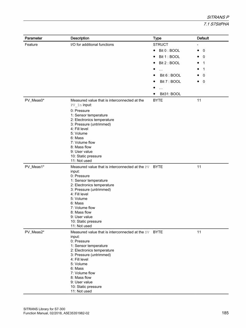
Parameter Description Type DefaultFeature I/O for additional functions STRUCT
● Bit 0 : BOOL● Bit 1 : BOOL● Bit 2 : BOOL● …● Bit 6 : BOOL● Bit 7 : BOOL● …● Bit31: BOOL
-● 0● 0● 1● 1● 0● 0
PV_Meas0* Measured value that is interconnected at the PV_In input:0: Pressure1: Sensor temperature2: Electronics temperature3: Pressure (untrimmed)4: Fill level5: Volume6: Mass7: Volume flow8: Mass flow9: User value10: Static pressure11: Not used
BYTE 11
PV_Meas1* Measured value that is interconnected at the PV input:0: Pressure1: Sensor temperature2: Electronics temperature3: Pressure (untrimmed)4: Fill level5: Volume6: Mass7: Volume flow8: Mass flow9: User value10: Static pressure11: Not used
BYTE 11
PV_Meas2* Measured value that is interconnected at the SV input:0: Pressure1: Sensor temperature2: Electronics temperature3: Pressure (untrimmed)4: Fill level5: Volume6: Mass7: Volume flow8: Mass flow9: User value10: Static pressure11: Not used
BYTE 11
SITRANS P7.1 S7SitPHA
SITRANS Library for S7-300Function Manual, 02/2018, A5E35351982-02 185
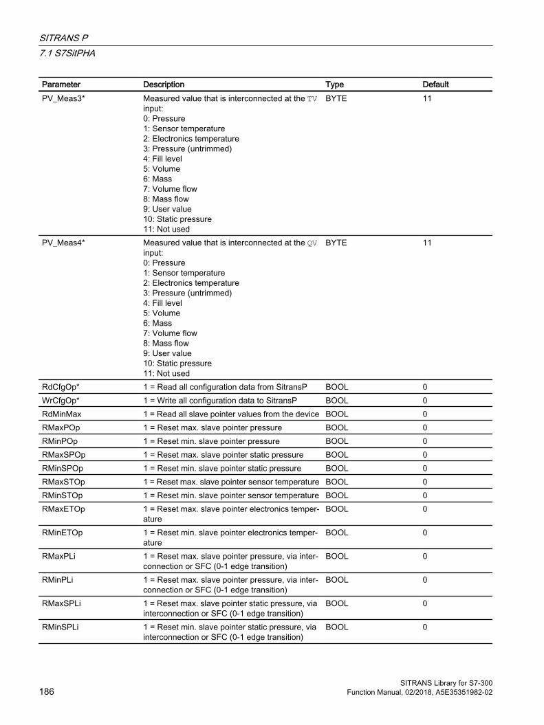
Parameter Description Type DefaultPV_Meas3* Measured value that is interconnected at the TV
input:0: Pressure1: Sensor temperature2: Electronics temperature3: Pressure (untrimmed)4: Fill level5: Volume6: Mass7: Volume flow8: Mass flow9: User value10: Static pressure11: Not used
BYTE 11
PV_Meas4* Measured value that is interconnected at the QV input:0: Pressure1: Sensor temperature2: Electronics temperature3: Pressure (untrimmed)4: Fill level5: Volume6: Mass7: Volume flow8: Mass flow9: User value10: Static pressure11: Not used
BYTE 11
RdCfgOp* 1 = Read all configuration data from SitransP BOOL 0WrCfgOp* 1 = Write all configuration data to SitransP BOOL 0RdMinMax 1 = Read all slave pointer values from the device BOOL 0RMaxPOp 1 = Reset max. slave pointer pressure BOOL 0RMinPOp 1 = Reset min. slave pointer pressure BOOL 0RMaxSPOp 1 = Reset max. slave pointer static pressure BOOL 0RMinSPOp 1 = Reset min. slave pointer static pressure BOOL 0RMaxSTOp 1 = Reset max. slave pointer sensor temperature BOOL 0RMinSTOp 1 = Reset min. slave pointer sensor temperature BOOL 0RMaxETOp 1 = Reset max. slave pointer electronics temper‐
atureBOOL 0
RMinETOp 1 = Reset min. slave pointer electronics temper‐ature
BOOL 0
RMaxPLi 1 = Reset max. slave pointer pressure, via inter‐connection or SFC (0-1 edge transition)
BOOL 0
RMinPLi 1 = Reset max. slave pointer pressure, via inter‐connection or SFC (0-1 edge transition)
BOOL 0
RMaxSPLi 1 = Reset max. slave pointer static pressure, via interconnection or SFC (0-1 edge transition)
BOOL 0
RMinSPLi 1 = Reset min. slave pointer static pressure, via interconnection or SFC (0-1 edge transition)
BOOL 0
SITRANS P7.1 S7SitPHA
SITRANS Library for S7-300186 Function Manual, 02/2018, A5E35351982-02

Parameter Description Type DefaultRMaxSTLi 1 = Reset max. slave pointer sensor tempera‐
ture, via interconnection or SFC (0-1 edge tran‐sition)
BOOL 0
RMinSTLi 1 = Reset min. slave pointer sensor temperature, via interconnection or SFC (0-1 edge transition)
BOOL 0
RMaxETLi 1 = Reset max. slave pointer electronics temper‐ature, via interconnection or SFC (0-1 edge tran‐sition)
BOOL 0
RMinETLi 1 = Reset min. slave pointer electronics temper‐ature, via interconnection or SFC (0-1 edge tran‐sition)
BOOL 0
RdMinMaxLi 1 = Read all slave pointer values from the device, via interconnection or SFC (0-1 edge transition)
BOOL 0
ScaleInH* High limit of measuring range of the 4 to 20 mA signalThis input is only used to read back the values to the CFC.
REAL 0.0
ScaleInL* Low limit of measuring range of the 4 to 20 mA signalThis input is only used to read back the values to the CFC.
REAL 0.0
* Values can be written back to these inputs during processing of the block by the block algorithm.
In/out parameters
Parameter Description Type DefaultAcyclData Acyclic data from driver block PiDr64 (intercon‐
nect this input with AcyclData output of PiDr64 )STRUCT● SlotRd : INT● …● RetValWr: WORD● Input : STRUCT● Output : STRUCT● NewDiag : INT● DiagData : STRUCT
Output parameters
Parameter Description Type DefaultQWronDev 1 = Wrong device connected BOOL 1PV_Out0 Process value output (4 to 20 mA signal) STRUCT
● Value : REAL● ST: BYTE
-● 0.0● 16#80
SITRANS P7.1 S7SitPHA
SITRANS Library for S7-300Function Manual, 02/2018, A5E35351982-02 187
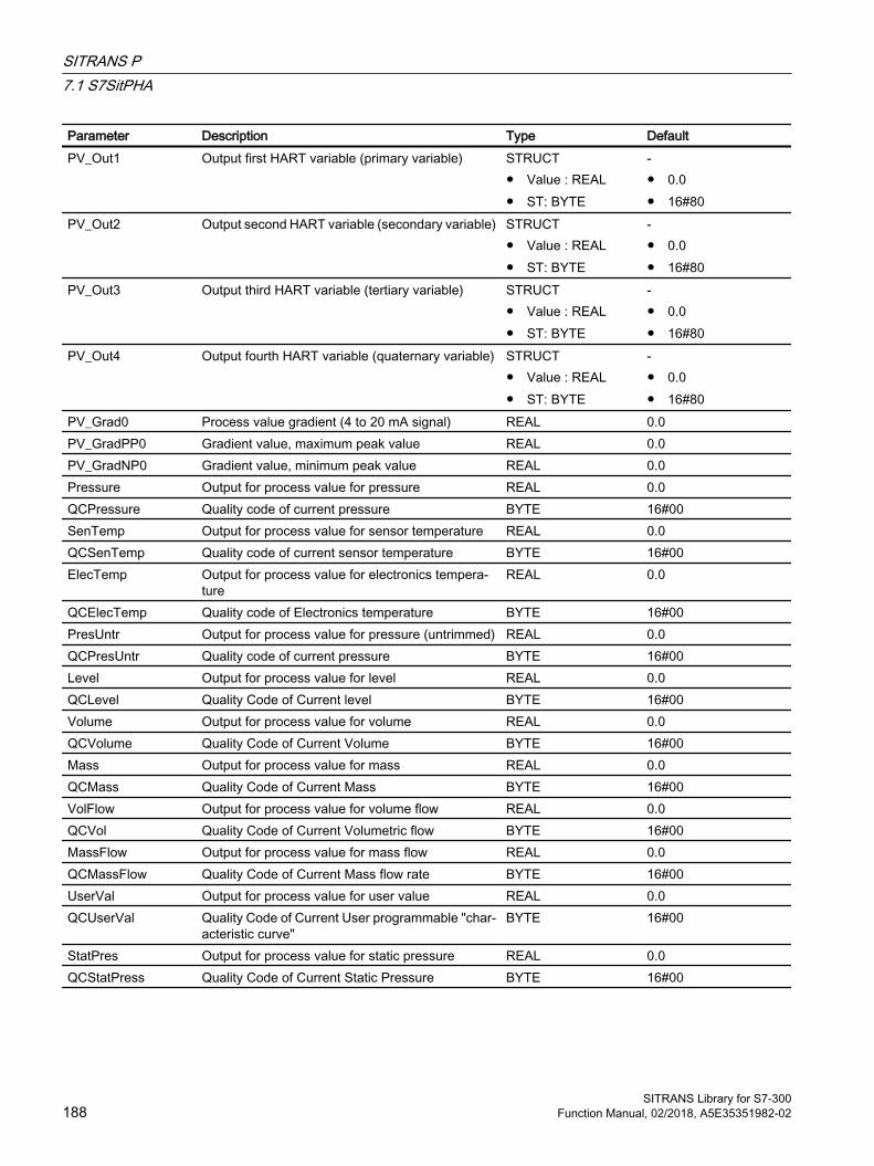
Parameter Description Type DefaultPV_Out1 Output first HART variable (primary variable) STRUCT
● Value : REAL● ST: BYTE
-● 0.0● 16#80
PV_Out2 Output second HART variable (secondary variable) STRUCT● Value : REAL● ST: BYTE
-● 0.0● 16#80
PV_Out3 Output third HART variable (tertiary variable) STRUCT● Value : REAL● ST: BYTE
-● 0.0● 16#80
PV_Out4 Output fourth HART variable (quaternary variable) STRUCT● Value : REAL● ST: BYTE
-● 0.0● 16#80
PV_Grad0 Process value gradient (4 to 20 mA signal) REAL 0.0PV_GradPP0 Gradient value, maximum peak value REAL 0.0PV_GradNP0 Gradient value, minimum peak value REAL 0.0Pressure Output for process value for pressure REAL 0.0QCPressure Quality code of current pressure BYTE 16#00SenTemp Output for process value for sensor temperature REAL 0.0QCSenTemp Quality code of current sensor temperature BYTE 16#00ElecTemp Output for process value for electronics tempera‐
tureREAL 0.0
QCElecTemp Quality code of Electronics temperature BYTE 16#00PresUntr Output for process value for pressure (untrimmed) REAL 0.0QCPresUntr Quality code of current pressure BYTE 16#00Level Output for process value for level REAL 0.0QCLevel Quality Code of Current level BYTE 16#00Volume Output for process value for volume REAL 0.0QCVolume Quality Code of Current Volume BYTE 16#00Mass Output for process value for mass REAL 0.0QCMass Quality Code of Current Mass BYTE 16#00VolFlow Output for process value for volume flow REAL 0.0QCVol Quality Code of Current Volumetric flow BYTE 16#00MassFlow Output for process value for mass flow REAL 0.0QCMassFlow Quality Code of Current Mass flow rate BYTE 16#00UserVal Output for process value for user value REAL 0.0QCUserVal Quality Code of Current User programmable "char‐
acteristic curve"BYTE 16#00
StatPres Output for process value for static pressure REAL 0.0QCStatPress Quality Code of Current Static Pressure BYTE 16#00
SITRANS P7.1 S7SitPHA
SITRANS Library for S7-300188 Function Manual, 02/2018, A5E35351982-02
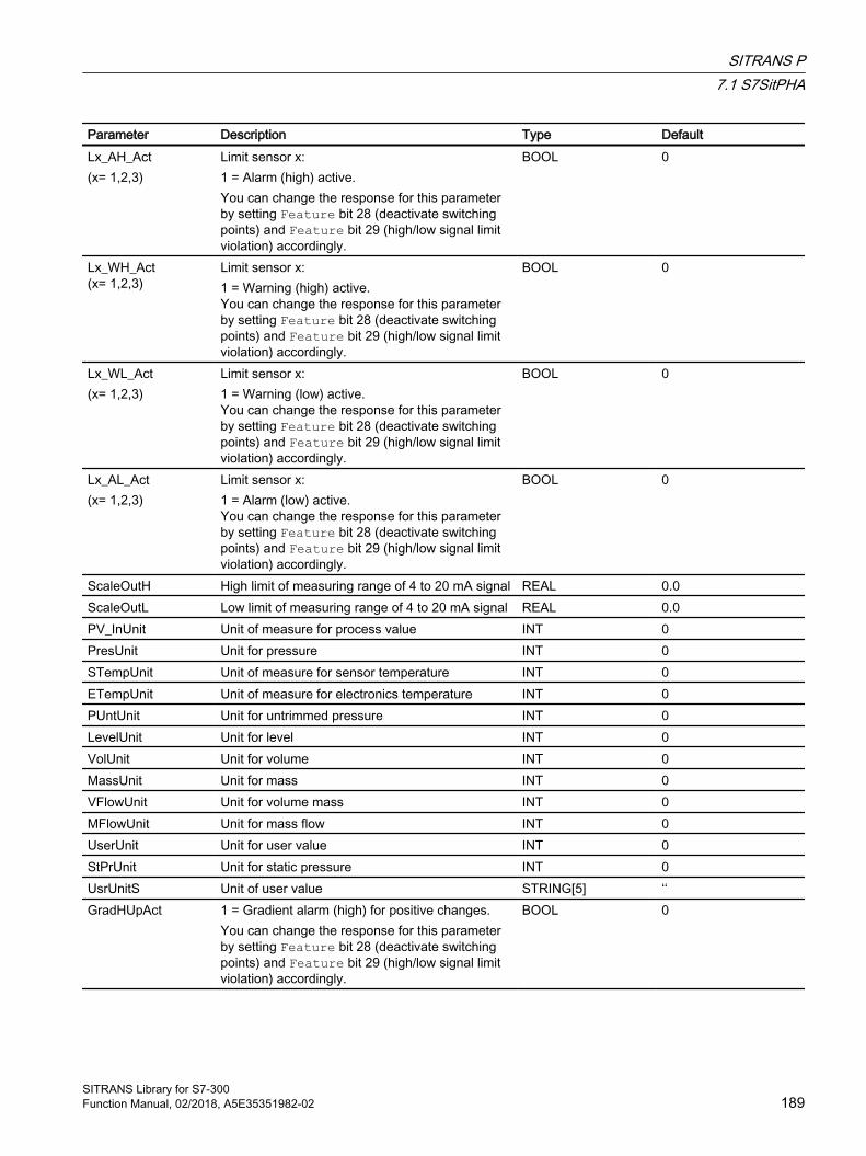
Parameter Description Type DefaultLx_AH_Act(x= 1,2,3)
Limit sensor x:1 = Alarm (high) active. You can change the response for this parameter by setting Feature bit 28 (deactivate switching points) and Feature bit 29 (high/low signal limit violation) accordingly.
BOOL 0
Lx_WH_Act(x= 1,2,3)
Limit sensor x:1 = Warning (high) active. You can change the response for this parameter by setting Feature bit 28 (deactivate switching points) and Feature bit 29 (high/low signal limit violation) accordingly.
BOOL 0
Lx_WL_Act(x= 1,2,3)
Limit sensor x:1 = Warning (low) active. You can change the response for this parameter by setting Feature bit 28 (deactivate switching points) and Feature bit 29 (high/low signal limit violation) accordingly.
BOOL 0
Lx_AL_Act(x= 1,2,3)
Limit sensor x:1 = Alarm (low) active. You can change the response for this parameter by setting Feature bit 28 (deactivate switching points) and Feature bit 29 (high/low signal limit violation) accordingly.
BOOL 0
ScaleOutH High limit of measuring range of 4 to 20 mA signal REAL 0.0ScaleOutL Low limit of measuring range of 4 to 20 mA signal REAL 0.0PV_InUnit Unit of measure for process value INT 0PresUnit Unit for pressure INT 0STempUnit Unit of measure for sensor temperature INT 0ETempUnit Unit of measure for electronics temperature INT 0PUntUnit Unit for untrimmed pressure INT 0LevelUnit Unit for level INT 0VolUnit Unit for volume INT 0MassUnit Unit for mass INT 0VFlowUnit Unit for volume mass INT 0MFlowUnit Unit for mass flow INT 0UserUnit Unit for user value INT 0StPrUnit Unit for static pressure INT 0UsrUnitS Unit of user value STRING[5] ‘‘GradHUpAct 1 = Gradient alarm (high) for positive changes.
You can change the response for this parameter by setting Feature bit 28 (deactivate switching points) and Feature bit 29 (high/low signal limit violation) accordingly.
BOOL 0
SITRANS P7.1 S7SitPHA
SITRANS Library for S7-300Function Manual, 02/2018, A5E35351982-02 189
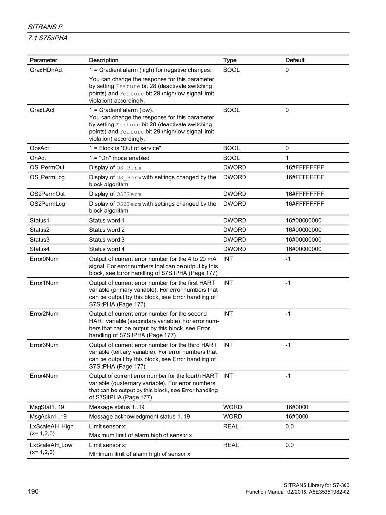
Parameter Description Type DefaultGradHDnAct 1 = Gradient alarm (high) for negative changes.
You can change the response for this parameter by setting Feature bit 28 (deactivate switching points) and Feature bit 29 (high/low signal limit violation) accordingly.
BOOL 0
GradLAct 1 = Gradient alarm (low). You can change the response for this parameter by setting Feature bit 28 (deactivate switching points) and Feature bit 29 (high/low signal limit violation) accordingly.
BOOL 0
OosAct 1 = Block is "Out of service" BOOL 0OnAct 1 = "On" mode enabled BOOL 1OS_PermOut Display of OS_Perm DWORD 16#FFFFFFFFOS_PermLog Display of OS_Perm with settings changed by the
block algorithmDWORD 16#FFFFFFFF
OS2PermOut Display of OS2Perm DWORD 16#FFFFFFFFOS2PermLog Display of OS2Perm with settings changed by the
block algorithmDWORD 16#FFFFFFFF
Status1 Status word 1 DWORD 16#00000000Status2 Status word 2 DWORD 16#00000000Status3 Status word 3 DWORD 16#00000000Status4 Status word 4 DWORD 16#00000000Error0Num Output of current error number for the 4 to 20 mA
signal. For error numbers that can be output by this block, see Error handling of S7SitPHA (Page 177)
INT -1
Error1Num Output of current error number for the first HART variable (primary variable). For error numbers that can be output by this block, see Error handling of S7SitPHA (Page 177)
INT -1
Error2Num Output of current error number for the second HART variable (secondary variable). For error num‐bers that can be output by this block, see Error handling of S7SitPHA (Page 177)
INT -1
Error3Num Output of current error number for the third HART variable (tertiary variable). For error numbers that can be output by this block, see Error handling of S7SitPHA (Page 177)
INT -1
Error4Num Output of current error number for the fourth HART variable (quaternary variable). For error numbers that can be output by this block, see Error handling of S7SitPHA (Page 177)
INT -1
MsgStat1..19 Message status 1..19 WORD 16#0000MsgAckn1..19 Message acknowledgment status 1..19 WORD 16#0000LxScaleAH_High(x= 1,2,3)
Limit sensor x:Maximum limit of alarm high of sensor x
REAL 0.0
LxScaleAH_Low(x= 1,2,3)
Limit sensor x:Minimum limit of alarm high of sensor x
REAL 0.0
SITRANS P7.1 S7SitPHA
SITRANS Library for S7-300190 Function Manual, 02/2018, A5E35351982-02

Parameter Description Type DefaultLxScaleWH_High(x= 1,2,3)
Limit sensor x:Maximum limit of warning high of sensor x
REAL 0.0
LxScaleWH_Low(x= 1,2,3)
Limit sensor x:Minimum limit of warning high of sensor x
REAL 0.0
LxScaleHyst_High(x= 1,2,3)
Limit sensor x:Maximum limit of hysteresis
REAL 0.0
LxScaleAL_High(x= 1,2,3)
Limit sensor x:Maximum limit of alarm low of sensor x
REAL 0.0
LxScaleAL_Low(x= 1,2,3)
Limit sensor x:Mininmum limit of alarm low of sensor x
REAL 0.0
LxScaleWL_High(x= 1,2,3)
Limit sensor x:Maximum limit of warning low of sensor x
REAL 0.0
LxScaleWL_Low(x= 1,2,3)
Limit sensor x:Mininmum limit of warning low of sensor x
REAL 0.0
Lx_AH_Lim(x= 1,2,3)
Limit sensor x:Alarm limit (high)
REAL 0.0
Lx_WH_Lim(x= 1,2,3)
Limit sensor x:Warning limit (high)
REAL 0.0
Lx_WL_Lim(x= 1,2,3)
Limit sensor x:Limit warning (low)
REAL 0.0
Lx_AL_Lim(x= 1,2,3)
Limit sensor x:Alarm limit (low)
REAL 0.0
Lx_Hyst(x= 1,2,3)
Limit sensor x:Hysteresis for alarm and warning limits
REAL 0.0
Lx_RespT(x= 1,2,3)
Limit sensor x:Response time
INT 0
PV_AH_Lim Alarm limit (high) if a limit sensor monitors PV_In REAL 0.0PV_WH_Lim Warning limit (high) if a limit sensor monitors PV_In REAL 0.0PV_WL_Lim Warning limit (low) if a limit sensor monitors PV_In REAL 0.0PV_AL_Lim Alarm limit (low) if a limit sensor monitors PV_In REAL 0.0MaxPRst Maximum value of resettable slave pointer for pres‐
sureREAL 0.0
MinPRst Minimum value of resettable slave pointer for pres‐sure
REAL 0.0
MaxSPRst Maximum value of resettable slave pointer for stat‐ic pressure
REAL 0.0
MinSPRst Minimum value of resettable slave pointer for static pressure
REAL 0.0
MaxSTRst Maximum value of resettable slave pointer for sen‐sor temperature
REAL 0.0
MinSTRst Minimum value of resettable slave pointer for sen‐sor temperature
REAL 0.0
SITRANS P7.1 S7SitPHA
SITRANS Library for S7-300Function Manual, 02/2018, A5E35351982-02 191

Parameter Description Type DefaultMaxETRst Maximum value of resettable slave pointer for elec‐
tronics temperatureREAL 0.0
MinETRst Minimum value of resettable slave pointer for elec‐tronics temperature
REAL 0.0
7.1.7 Block diagram of S7SitPHAA block diagram is not provided for this block.
7.1.8 Template of S7SitPHAThis process tag type is used to connect a SITRANS P with SCALING driver blocks to STEP 7 (template 'SitransP HART').
Note
The SCALE function takes an integer value (IN) and converts it to a real value in engineering units scaled between a low and a high limit (LO_LIM and HI_LIM). For more information on Scaling block press F1 for online help.
The Scaling block trims the value of PV_In . The inputs for the Hart auxiliary variables of the function block S7SitPHA (PV, SV, TV, QV) are interconnected with the corresponding input from HW Config.
The inputs Laddr, Addr.Laddr0 and Addr.Laddr1 of the PiDr64 block (AcyclicData) are configured with the address of the process value PV (not interconnected!).
The SlotHart input receives the slot number of the SITRANS P module within the analog input module at the SitransP (SitransP) block. The Feature bits 2 to 6 must be used to configure whether communication with the module is by means of the HART protocol and, if applicable, which HART variables are used. All required values can be found in HW Config.
Note
Correct configuration of the SlotHart input is a mandatory requirement and cannot be checked by the block.
SITRANS P7.1 S7SitPHA
SITRANS Library for S7-300192 Function Manual, 02/2018, A5E35351982-02

7.1.9 Operator control & monitoring
7.1.9.1 Views of S7SitPHA
Views of the SitransP blockThe SitransP block has the following views:
● Standard view of S7SitPHA (Page 194)
● Alarm view (Page 10)
● Limit view of S7SitPHA (Page 196)
● Trend view (Page 11)
● Parameter view of S7SitPHA (Page 199)
● Preview of S7SitPHA (Page 200)
● AUTOHOTSPOT
● Batch view (Page 9)
● Slave pointer view of S7SitPHA (resettable) (Page 201)
● Block icon for S7SitPHA (Page 203)
For general information on the faceplate and block icon, refer to the sections "Faceplate structure" and "Block icon structure" in the APL online help.
SITRANS P7.1 S7SitPHA
SITRANS Library for S7-300Function Manual, 02/2018, A5E35351982-02 193

7.1.9.2 Standard view of S7SitPHADepending on the configuration of the 4 to 20 mA signal and the up to four HART variables in the standard view, the current process values for pressure, sensor temperature, electronics temperature, pressure (untrimmed), level, volume, mass, volume flow, mass flow, user value and/or static pressure are displayed. If a measured value is not assigned to a variable, the field is hidden. The gradient values always refer to the 4 to 20 mA signal.
(1) Display and switchover of operating modeThis area provides information on the currently valid operating mode. The following operating modes can be shown here:
● On (see the APL online help)
● Out of service (see APL online help)
For more information on changing the operating mode, refer to the "Switching operating states and operating modes" section in the APL Online Help.
(2) High and low scale range for the process value (4 to 20 mA signal)These values provide information on the display range for the bar graph of the process value (4 to 20 mA signal). The scale range is set in the engineering system with the PV_OpScaleH/L parameter, see Display and operating range for process values and limits.
SITRANS P7.1 S7SitPHA
SITRANS Library for S7-300194 Function Manual, 02/2018, A5E35351982-02

(3) Display of process value (4 to 20 mA signal) including signal statusThis area indicates the current process value (4 to 20 mA signal) with the associated signal status. The name of the configured measured value is displayed depending on the PV_Meas0 variable, in this case "Pressure".
(4) High and low scale range for the gradient valueThese values provide information on the display range for the bar graph of the gradient. The scale range corresponds to 10% of the scale range for the process value (4 to 20 mA signal): If you have entered a scale range for the process value of 0 to 100, for example, the scale range for the gradient is automatically defined as -10 to 10.
The current gradient value is displayed if one of the monitoring functions is enabled:
● Gradient monitoring for positive changes (GradHUpEn = 1)
● Gradient monitoring for negative changes (GradHDnEn = 1)
● Gradient monitoring (GradLEn = 1)
(5) Display of gradientThis area shows the current, minimum and maximum gradient values of the 4 to 20 mA signal as well as rising and falling of the value. This display of the minimum and maximum gradient value functions like a slave pointer.
The current gradient value is displayed if one of the monitoring functions is enabled:
● Gradient monitoring for positive changes (GradHUpEn = 1)
● Gradient monitoring for negative changes (GradHDnEn = 1)
● Gradient monitoring (GradLEn = 1)
The maximum peak gradient value is displayed if the gradient monitoring function for positive changes is enabled (GradHUpEn = 1)
The minimum peak gradient value is displayed if the gradient monitoring function for negative changes is enabled (GradHDnEn = 1)
(6) Resetting of peak values of the gradientUsing these buttons you can reset the maximum or minimum peak value of the gradient (output parameters PV_GradPP0 and PV_GradNP0).
The button is displayed if the gradient monitoring function for positive (GradHUpEn = 1) or negative changes (GradHDnEn = 1) is enabled.
(7), (8) and (9) Display of HART variables including signal statusThis area provides information on the current process values of the HART variables with the corresponding signal status. The name of the configured measured value is displayed depending on the PV_Meas1...4 variable, in this case "Pressure, "Sensor temperature" and "Pressure (untrimmed)".
SITRANS P7.1 S7SitPHA
SITRANS Library for S7-300Function Manual, 02/2018, A5E35351982-02 195

(10) Display area for block stateThis area provides additional information on the operating state of the block:
● "Wrong device"
(11) Display area for switch permissionThis area provides the text of the current OS, according to the enumeration configured at the PERMIS input.
(12) Bar graph for the "Process value" (4 to 20 mA signal)This area shows the current "Process value" (4 to 20 mA signal) in the form of a bar graph. The visible area in the bar graph depends on the configuration in the engineering system (ES), see Display and operating range for process values and limits.
(13) Limit displayThese small, colored triangles indicate the specified limits in the respective bar graph. They are only visible if the 4 to 20 mA signal is monitored by a limiter.
7.1.9.3 Limit view of S7SitPHAThe process value limits of the up to three limit sensors and the limits for the gradient monitoring of the 4 to 20 mA signal can be specified in this two-part view. The displayed texts depend on the configuration of the limit sensors on the block or in the module.
SITRANS P7.1 S7SitPHA
SITRANS Library for S7-300196 Function Manual, 02/2018, A5E35351982-02

(1), (5) and (6) Process value limitsIn this area, you can enter the limits for the process value. You can change the following limits:
● "H alarm": High alarm
● "H warning": High warning
● "Hysteresis"
● "Delay time"
● "L warning": Low warning
● "L alarm": Low alarm
Depending on the configuration of the limit sensors, non-configured limits are not shown in the faceplate.
Note
The maximum and minimum values for the alarm and warning limits of the limiters 1 to 3 are configured at the inputs L1/2/3_ScaleH\L. If the Feature bit 7 (synchronize alarm configuration with module) is set, the measuring range limits available in the module are written to the corresponding L1/2/3_ScaleH\L inputs when reading the configuration data.
SITRANS P7.1 S7SitPHA
SITRANS Library for S7-300Function Manual, 02/2018, A5E35351982-02 197

(2) Gradient limits You can enter gradient limits in this area. Refer to the "Changing values" section in the APL online Help.
You can change the following limits:
● "H alarm ⇑": Gradient for the upper gradient for positive changes
● "H alarm ⇓": Gradient for the upper rate of rise for negative changes
● "L alarm ⇑⇓": Gradient for the lower rate of rise (absolute)
(3) Switching between the two faceplate viewsDisplay of the limits is divided between two faceplate views. It is possible to toggle between the two views here.
(4) Enabled operationsThis area shows all operations for which special operator authorizations are assigned. They depend on the configuration in the engineering system (ES) that applies to this block.
Symbols for enabled operations:
● Green check mark: The OS operator can control this parameter
● Gray check mark: The OS operator cannot control this parameter at this time due to the process
● Red cross: The OS operator cannot control this parameter due to the configured AS operator authorizations (OS_Perm or OS1Perm)
(7) Message suppression/delaysThe message suppression indicates whether suppression of the associated message is activated in the AS block using the xx_MsgEn parameter. The output of messages is not suppressed when the block is installed (all xx_MsgEn parameters are set to 1 by default). Messages can only be output if limit monitoring of the additional analog value has been enabled.
Alarm delays are also displayed in this state; refer to the "Application of alarm delays" section in the APL Online Help.
(8) Suppress messagesYou can activate/deactivate messages by selecting the check mark.
SITRANS P7.1 S7SitPHA
SITRANS Library for S7-300198 Function Manual, 02/2018, A5E35351982-02
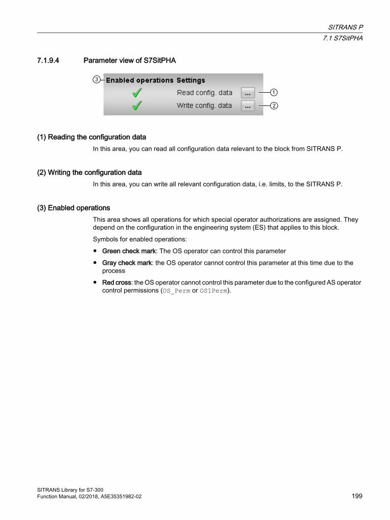
7.1.9.4 Parameter view of S7SitPHA
(1) Reading the configuration dataIn this area, you can read all configuration data relevant to the block from SITRANS P.
(2) Writing the configuration dataIn this area, you can write all relevant configuration data, i.e. limits, to the SITRANS P.
(3) Enabled operationsThis area shows all operations for which special operator authorizations are assigned. They depend on the configuration in the engineering system (ES) that applies to this block.
Symbols for enabled operations:
● Green check mark: The OS operator can control this parameter
● Gray check mark: the OS operator cannot control this parameter at this time due to the process
● Red cross: the OS operator cannot control this parameter due to the configured AS operator control permissions (OS_Perm or OS1Perm).
SITRANS P7.1 S7SitPHA
SITRANS Library for S7-300Function Manual, 02/2018, A5E35351982-02 199

7.1.9.5 Preview of S7SitPHA
(1) Process valuesThis area shows the real process values ( PV_In, PV, SV, TV, QV ).
(2) Navigation button to the standard view of any faceplateUse this navigation button to open the standard view of a block configured in the engineering system. The visibility of this navigation button depends on the configuration in the engineering system (ES).
You can find more information on this in the section "Opening additional faceplates" in the APL Online Help.
(3) Enabled operationsThis area shows all operations for which special operator authorizations are assigned. They depend on the configuration in the engineering system (ES) that applies to this block.
SITRANS P7.1 S7SitPHA
SITRANS Library for S7-300200 Function Manual, 02/2018, A5E35351982-02
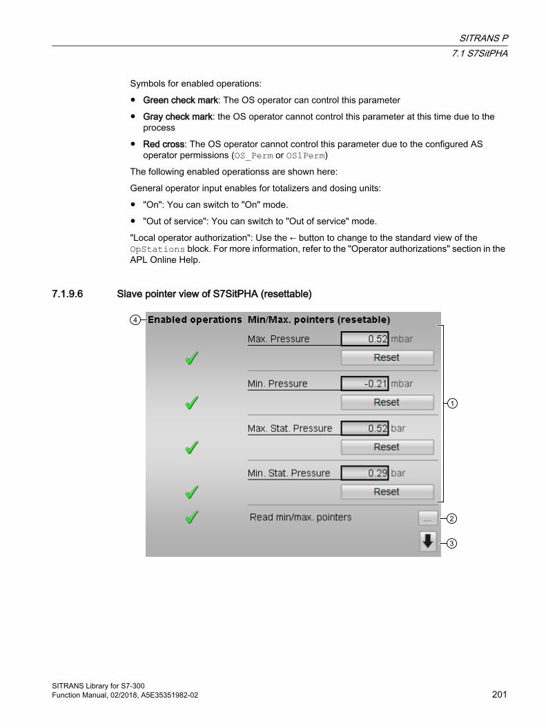
Symbols for enabled operations:
● Green check mark: The OS operator can control this parameter
● Gray check mark: the OS operator cannot control this parameter at this time due to the process
● Red cross: The OS operator cannot control this parameter due to the configured AS operator permissions (OS_Perm or OS1Perm)
The following enabled operationss are shown here:
General operator input enables for totalizers and dosing units:
● "On": You can switch to "On" mode.
● "Out of service": You can switch to "Out of service" mode.
"Local operator authorization": Use the ← button to change to the standard view of the OpStations block. For more information, refer to the "Operator authorizations" section in the APL Online Help.
7.1.9.6 Slave pointer view of S7SitPHA (resettable)
SITRANS P7.1 S7SitPHA
SITRANS Library for S7-300Function Manual, 02/2018, A5E35351982-02 201

(1) Display and reset resettable slave pointerThe last values of the resettable min/max pointer read from the device are shown in this area, and reset if applicable. Min/max pointers which are not available in the device are not displayed.
● Maximum value slave pointer for pressure
● Minimum value resettable slave pointer for pressure
● Maximum value slave pointer for static pressure
● Minimum value resettable slave pointer for static pressure
● Maximum value slave pointer for sensor temperature
● Minimum value slave pointer for sensor temperature
● Maximum value slave pointer for electronics temperature
● Minimum value slave pointer for electronics temperature
(2) Read out min/max pointersIn this area, you can read out the values of all slave pointers from the module
(3) Switching between the two faceplate viewsDisplay of the slave pointers is divided between two faceplate views. It is possible to toggle between the two views here.
SITRANS P7.1 S7SitPHA
SITRANS Library for S7-300202 Function Manual, 02/2018, A5E35351982-02
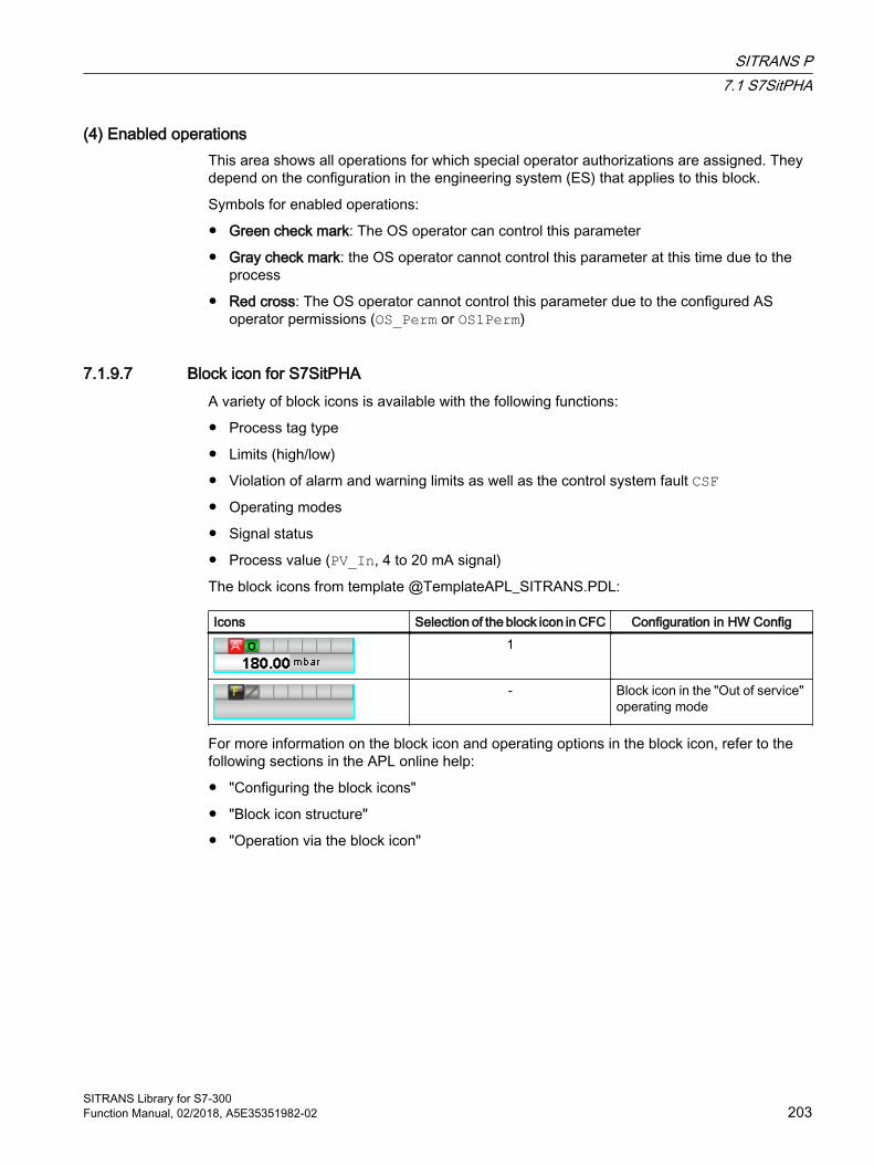
(4) Enabled operationsThis area shows all operations for which special operator authorizations are assigned. They depend on the configuration in the engineering system (ES) that applies to this block.
Symbols for enabled operations:
● Green check mark: The OS operator can control this parameter
● Gray check mark: the OS operator cannot control this parameter at this time due to the process
● Red cross: The OS operator cannot control this parameter due to the configured AS operator permissions (OS_Perm or OS1Perm)
7.1.9.7 Block icon for S7SitPHAA variety of block icons is available with the following functions:
● Process tag type
● Limits (high/low)
● Violation of alarm and warning limits as well as the control system fault CSF● Operating modes
● Signal status
● Process value (PV_In, 4 to 20 mA signal)
The block icons from template @TemplateAPL_SITRANS.PDL:
Icons Selection of the block icon in CFC Configuration in HW Config1
- Block icon in the "Out of service" operating mode
For more information on the block icon and operating options in the block icon, refer to the following sections in the APL online help:
● "Configuring the block icons"
● "Block icon structure"
● "Operation via the block icon"
SITRANS P7.1 S7SitPHA
SITRANS Library for S7-300Function Manual, 02/2018, A5E35351982-02 203

SITRANS P7.1 S7SitPHA
SITRANS Library for S7-300204 Function Manual, 02/2018, A5E35351982-02
SITRANS F M MAG 6000 88.1 S7Mag6T
8.1.1 Description of S7Mag6T
Object name (type + number) and family Type + number: FB 2605
Family: MAG6000
Note
The S7Mag6T block and its faceplate are oriented to the function principle of the PCS 7 APL Library that is not explained in detail in this document. The APL Manual is available for download from the Internet at Siemens Customer Support, http://support.automation.siemens.com/WW/view/de/57265842 (contribution ID:57265842).
Area of application for S7Mag6T The block is used for the following applications:
● Interface block of the MAG6000 driver blocks for the user program and visualization
How it works The S7Mag6T prepares the process and diagnostics data received from MAG6000 driver blocks for further use in the user program and for visualization. Inputs via the faceplate or block inputs are transferred by driver blocks to the MAG6000.In accordance with the configuration of the MAG6000 in the HW Config, the function block supports one or two totalizers or, instead of the second totalizer, the dosing functionality of the MAG6000.
Configuration Use the CFC editor to install the block in a cyclic interrupt OB (OB30 to OB38). The block is also installed automatically in the startup OB (OB100).
Moreover, to connect the I/O signals it is imperative to call the driver blocks FbMag6T (cyclic data) and PiDr64 (non-cyclic data) in the same interrupt OB and startup OB (OB100) before S7Mag6T is called. The CyclData output structure of the PiDr64 block and the AcyclData output structure of the FbMag6T block are interconnected with the inputs of the same name at the S7Mag6T block.
SITRANS Library for S7-300Function Manual, 02/2018, A5E35351982-02 205
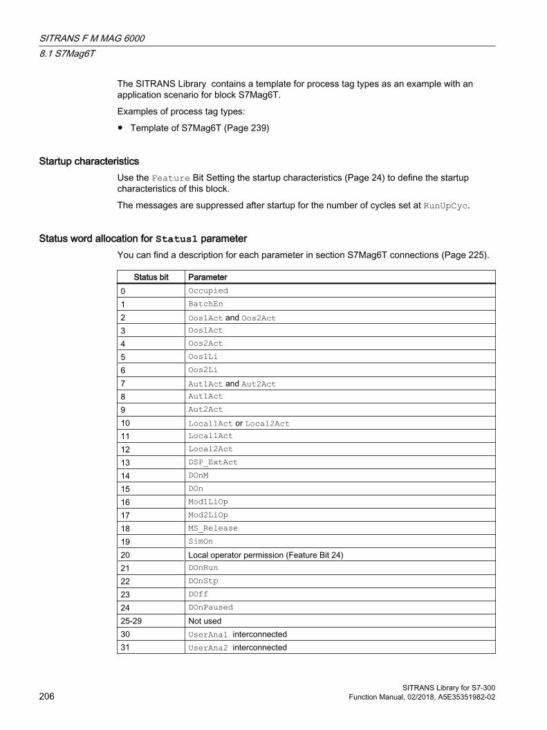
The SITRANS Library contains a template for process tag types as an example with an application scenario for block S7Mag6T.
Examples of process tag types:
● Template of S7Mag6T (Page 239)
Startup characteristics Use the Feature Bit Setting the startup characteristics (Page 24) to define the startup characteristics of this block.
The messages are suppressed after startup for the number of cycles set at RunUpCyc.
Status word allocation for Status1 parameter You can find a description for each parameter in section S7Mag6T connections (Page 225).
Status bit Parameter0 Occupied1 BatchEn2 Oos1Act and Oos2Act3 Oos1Act4 Oos2Act5 Oos1Li6 Oos2Li7 Aut1Act and Aut2Act8 Aut1Act9 Aut2Act10 Local1Act or Local2Act11 Local1Act12 Local2Act13 DSP_ExtAct14 DOnM15 DOn16 Mod1LiOp17 Mod2LiOp18 MS_Release19 SimOn20 Local operator permission (Feature Bit 24)21 DOnRun22 DOnStp23 DOff24 DOnPaused25-29 Not used30 UserAna1 interconnected31 UserAna2 interconnected
SITRANS F M MAG 60008.1 S7Mag6T
SITRANS Library for S7-300206 Function Manual, 02/2018, A5E35351982-02

Status word allocation for Status2 parameter
Status bit Parameter0 Flow1 VF_AH_Act2 VF_WH_Act3 VF_WL_Act4 VF_AL_Act5 Tot1_AH_Act6 Tot1_WH_Act7 Tot1_WL_Act8 Tot1_AL_Act9 Tot2_AH_Act10 Tot2_WH_Act11 Tot2_WL_Act12 Tot2_AL_Act13 Totalizer1 counts in balanced mode (ModeTot1 = 16#00)14 Totalizer1 counts only in positive mode (ModeTot1 = 16#01)15 Totalizer1 counts only in negative mode (ModeTot1 = 16#02)16 Totalizer1 counts in Hold state (ModeTot1 = 16#03)17 Totalizer2 counts in balanced mode (ModeTot2 = 16#00)18 Totalizer2 counts only in positive mode (ModeTot2 = 16#01)19 Totalizer2 counts only in negative mode (ModeTot2 = 16#02)20 Totalizer2 counts in Hold state (ModeTot2 = 16#03)21 Invalid signal status22 Totalizer 1 is configured (CyclData.ParaAvail.Bit0)23 Totalizer 2 is configured (CyclData.ParaAvail.Bit1)24 Dosing status (B_STA) is configured (CyclData.ParaAvail.Bit2)25 Reset Totalizer 1 (SET_TOT) is configured (CyclData.ParaAvail.Bit3)26 Command for Totalizer 1 (MODE_TOT) is configured (CyclData.ParaAvail.Bit4)27 Reset Totalizer 2 (SET_TOT) is configured (CyclData.ParaAvail.Bit5)28 Command for Totalizer 2 (MODE_TOT) is configured (CyclData.ParaAvail.Bit6)29 Dosing command (B_CTR) is configured (CyclData.ParaAvail.Bit7)30 Dosing setpoint (SETP) is configured (CyclData.ParaAvail.Bit8)31 Dosing compensation (COMP) is configured (CyclData.ParaAvail.Bit9)
Status word allocation for Status3 parameter
Status bit Parameter0 VF_AH_En1 VF_WH_En2 VF_WL_En3 VF_AL_En4 Tot1_AH_En
SITRANS F M MAG 60008.1 S7Mag6T
SITRANS Library for S7-300Function Manual, 02/2018, A5E35351982-02 207

Status bit Parameter5 Tot1_WH_En6 Tot1_WL_En7 Tot1_AL_En8 Tot2_AH_En9 Tot2_WH_En
10 Tot2_WL_En11 Tot2_AL_En12 VF_AH_MsgEn13 VF_WH_MsgEn14 VF_WL_MsgEn15 VF_AL_MsgEn16 Tot1_AH_MsgEn17 Tot1_WH_MsgEn18 Tot1_WL_MsgEn19 Tot1_AL_MsgEn20 Tot2_AH_MsgEn21 Tot2_WH_MsgEn22 Tot2_WL_MsgEn23 Tot2_AL_MsgEn24 Not used25 Not used26 Dosing timeout (DiagData.W22)27 Dribbling dosing (DiagData.W23)28 Negative dosing flow (DiagData.W24)29 Not used30 Any diagnostics message active (DiagData.xxx <> 0)31 MsgLock
Status word allocation for Status4 parameter
Status bit Parameter0 "Interlock" button is enabled1 "Permission" button is enabled2 "Protection" button is enabled3 1 = Intlockis active4 1 = Permitis active5 1 = Protectis active6 "Interlock", "Permit" or "Protect" is enabled7 "Interlock", "Permit" or "Protect" is active8 ForceDSrt9 ForceDStp10 ForceDPause
SITRANS F M MAG 60008.1 S7Mag6T
SITRANS Library for S7-300208 Function Manual, 02/2018, A5E35351982-02
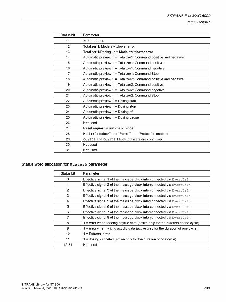
Status bit Parameter11 ForceDCont12 Totalizer 1: Mode switchover error13 Totalizer 1/Dosing unit: Mode switchover error14 Automatic preview 1 = Totalizer1: Command positive and negative15 Automatic preview 1 = Totalizer1: Command positive16 Automatic preview 1 = Totalizer1: Command negative17 Automatic preview 1 = Totalizer1: Command Stop18 Automatic preview 1 = Totalizer2: Command positive and negative19 Automatic preview 1 = Totalizer2: Command positive20 Automatic preview 1 = Totalizer2: Command negative21 Automatic preview 1 = Totalizer2: Command Stop22 Automatic preview 1 = Dosing start23 Automatic preview 1 = Dosing stop24 Automatic preview 1 = Dosing off25 Automatic preview 1 = Dosing pause26 Not used27 Reset request in automatic mode28 Neither "Interlock", nor "Permit", nor "Protect" is enabled29 Oos1Li and Oos2Li if both totalizers are configured30 Not used31 Not used
Status word allocation for Status5 parameter
Status bit Parameter0 Effective signal 1 of the message block interconnected via EventTsIn1 Effective signal 2 of the message block interconnected via EventTsIn2 Effective signal 3 of the message block interconnected via EventTsIn3 Effective signal 4 of the message block interconnected via EventTsIn4 Effective signal 5 of the message block interconnected via EventTsIn5 Effective signal 6 of the message block interconnected via EventTsIn6 Effective signal 7 of the message block interconnected via EventTsIn7 Effective signal 8 of the message block interconnected via EventTsIn8 1 = error when reading acyclic data (active only for the duration of one cycle)9 1 = error when writing acyclic data (active only for the duration of one cycle)
10 1 = External error11 1 = dosing canceled (active only for the duration of one cycle)
12-31 Not used
SITRANS F M MAG 60008.1 S7Mag6T
SITRANS Library for S7-300Function Manual, 02/2018, A5E35351982-02 209
8.1.2 Operating modes of S7Mag6T
Operating modes of S7Mag6T The block can be operated using the following modes:
● Local mode
● Automatic mode
● Manual mode
● Out of service
Totalizers 1 and 2, or the dosing unit are assigned independent, separate operating modes.
The general descriptions of the operating modes are identical for S7Mag6T and the APL; refer to the Online Help for the standard APL blocks.
The next section provides additional block-specific information relating to the general descriptions.
"Local mode""Local mode" supports the transfer of the following commands to the totalizers 1 or 2:
● "Start balanced" (positive edge Bal1Local or Bal2Local)
● "Positive" (positive edge Pos1Local or Pos2Local)
● "Negative" (positive edge Neg1Local or Neg2Local)
● "Hold" (Hold1Local or Hold2Local= 1)
"Local mode" supports the transfer of the following commands to the dosing unit:
● "Start" (positive edge DSrtLocal)
● "Continue dosing" (DContLocal = 1)
● "Pause dosing" (DPauseLocal = 1)
● "Stop dosing" (DStpLocal = 1)
If you set the block to "Local mode", the control is only influenced by the "local" signals of the totalizers (input parameters Bal1Local/Bal2Local = 1, Pos1Local/Pos2Local = 1, Neg1Local/Neg2Local = 1 and Hold1Local/Hold2Local = 1) or of the dosing unit (input parameters DSrtLocal = 1, DContLocal = 1, DPauseLocal = 1 and DStpLocal = 1).
Note
Unlike the general description, at the LocalSetting parameter only the values 0, 1 and 3 can be set, i.e. tracking in "local" mode is not possible with S7Mag6T.
SITRANS F M MAG 60008.1 S7Mag6T
SITRANS Library for S7-300210 Function Manual, 02/2018, A5E35351982-02

"Automatic mode""Automatic mode" supports the transfer of the following commands to the totalizers 1 or 2:
● "Start balanced" (positive edge Bal1Aut or Bal2Aut)
● "Positive" (positive edge Pos1Aut or Pos2Aut)
● "Negative" (positive edge Neg1Aut or Neg2Aut)
● "Hold" (Hold1Aut or Hold2Aut= 1)
"Automatic mode" supports the transfer of the following commands to the dosing unit:
● "Start" (positive edge DSrtAut)
● "Continue dosing" (DContAut = 1)
● "Pause dosing" (DPauseAut = 1)
● "Stop dosing" (DStpAut = 1)
"Manual mode""Manual mode" enables the transfer of the following commands to the totalizers 1 or 2:
● "Start balanced" (positive edge Bal1Man or Bal2Man)
● "Positive" (positive edge Pos1Man or Pos2Man)
● "Negative" (positive edge Neg1Man or Neg2Man)
● "Hold" (Hold1Man or Hold2Man= 1)
"Manual mode" enables the transfer of the following commands to the dosing unit:
● "Start" (positive edge DSrtMan)
● "Continue dosing" (DContMan = 1)
● "Pause dosing" (DPauseMan = 1)
● "Stop dosing" (DStpMan = 1)
"Out of service"The block is not entirely "out of service" unless both totalizers are out of service. For general information about the "out of service" mode, refer to the APL Online Help
8.1.3 Functions of S7Mag6T
Functions of S7Mag6T The functions for this block are listed below.
SITRANS F M MAG 60008.1 S7Mag6T
SITRANS Library for S7-300Function Manual, 02/2018, A5E35351982-02 211

Configuration data All configuration data is read at the CPU startup or after rack recovery, depending on the feature bits 8. You may also initiate this procedure with "Read configuration data" in the parameter view of the faceplates.
All writable configuration data of MAG6000 is transferred by means of cyclic services to MAG6000 at the change of the corresponding block input and is then read back. The respective output always shows the last readback value. You may also use a faceplate control to write the configuration data.
Function block S7Mag6T provides the following configuration data with the corresponding slot/index address in MAG6000:
Description Block parameters (I/O) read/write ena‐bled
Slot In‐dex
Units for volume flow and to‐talizers 1 and 2
InVFUnit/VFUnit, InTot1Unit/Tot1Unit, InTot2Unit/Tot2Unit
LLL
123
282727
Limits for the volume flow display in faceplates
InVF_OpScale/VF_OpScale R/W 1 28
Volume flow limits and hys‐teresis
InVF_AH_Lim/VF_AH_Lim, InVF_WH_Lim/VF_WH_Lim, InVF_WL_Lim/VF_WL_Lim, InVF_AL_Lim/VF_AL_Lim, InVF_Hyst/VF_Hyst
R/WR/WR/WR/WR/W
11111
3739414335
Totalizer 1 limits and hyste‐resis
InTot1_AH_Lim/Tot1_AH_Lim, InTot1_WH_Lim/Tot1_WH_Lim, InTot1_WL_Lim/Tot1_WL_Lim, InTot1_AL_Lim/Tot1_AL_Lim, InTot1_Hyst/Tot1_Hyst
R/WR/WR/WR/WR/W
22222
3435363833
Totalizer 2/dosing unit limits and hysteresis
InTot2_AH_Lim/Tot2_AH_Lim, InTot2_WH_Lim/Tot2_WH_Lim, InTot2_WL_Lim/Tot2_WL_Lim, InTot2_AL_Lim/Tot2_AL_Lim, InTot2_Hyst/Tot2_Hyst
R/WR/WR/WR/WR/W
33333
3435363723
Low flow cut-off suppression InZFlSupp/ZFlSupp R/W 1 217Dosing setpoint ---/DSP L*) 3 68Compensation of the dosing unit
DCompOp/CompOp L*) 3 69
Command Totalizer 1 internal use L**) 2 30Command Totalizer 2 internal use L**) 3 30
*) The dosing setpoint and compensation values are transferred by means of cyclic data and then read back in acyclic mode
**) The Totalizer 1 and 2 commands are retrieved at CPU startup to determine the current totalizer state (refer to Feature bit)
SITRANS F M MAG 60008.1 S7Mag6T
SITRANS Library for S7-300212 Function Manual, 02/2018, A5E35351982-02
Monitoring of volume flow limits You can monitor the high/low alarm and warning limits for volume flow:
● VF_AH_Lim: Limit for high alarm
● VF_AL_Lim: Limit for low alarm
● VF_WH_Lim: Limit for high warning
● VF_WL_Lim: Limit for low warning
To clear a limit overshoot/undershoot error, it is necessary to recover the value to hysteresis limits (VF_Hyst outputs).
Result of the limit monitoring The result of limit monitoring is returned at the interconnectable output parameters:
● VF_AH_Act = 1:Limit for high alarm reached or exceeded
● VF_AL_Act = 1:Limit for low alarm reached or undershot
● VF_WH_Act = 1:Limit for high warning reached or exceeded
● VF_WL_Act = 1:Limit for low warning reached or undershot
You can use Feature bit 29 (signal limit overshoot/undershoot) to determine whether the output parameter triggers limit monitoring with the value "0" or "1".
You may use Feature bit 28 (Disabling operating points) to disable limit monitoring while message suppression is active (MsgLock = 1).
Activating limit monitoringMonitoring is always enabled using the input parameters:
● VF_AH_En = 1: Monitoring of the high alarm limits
● VF_AL_En = 1: Monitoring of the low alarm limits
● VF_WH_En = 1: Monitoring of the high warning limits
● VF_WL_En = 1: Monitoring of the low warning limits
Predefinition: All monitoring functions are activated.
Message suppressionThe corresponding message is suppressed using the parameters:
● VF_AH_MsgEn = 0:Alarm (high) messages are suppressed.
● VF_AL_MsgEn = 0:Alarm (low) messages are suppressed.
SITRANS F M MAG 60008.1 S7Mag6T
SITRANS Library for S7-300Function Manual, 02/2018, A5E35351982-02 213
● VF_WH_MsgEn = 0:Warning (high) messages are suppressed.
● VF_WL_MsgEn = 0:Warning (low) messages are suppressed.
The output of messages is not suppressed when the block is installed (all xx_MsgEn parameters are preset to 1). Messages can only be output if limit monitoring of the additional analog value has been enabled.
Suppressing messages using the MsgLock parameterThis block provides the standard function "Suppress messages using parameter MsgLock“ that is described in the APL Online Help.
Selecting a unit of measureThe units of measure for Totalizers 1 and 2 are configured on the MAG6000 device by means of PDM and read a restart of the PLC when Feature bit 8 = TRUE, or after MAG6000 has returned to the Profibus, or by means of "Read Config" in the faceplate view.
Group errorThe following parameter is taken into consideration when forming the group error GrpErr:
● CyclData.Csf (external error)
Configurable reactions using the Feature I/OThe following response features are available for this block at the respective bits of the Feature I/O:
Bit number Meaning0 Setting the startup characteristics (Page 24) 1 Reaction to the out of service mode (Page 25) 2 Resetting the commands for changing the mode (Page 26) 3 Enabling resetting of commands for the control settings (Page 26) 4 Set switch or button mode (Page 27) 8 Read configuration data automatically (Page 28) 10 Exiting local mode (Page 28) 11 Pause dosing at flow alarm (Page 29) 17 Activating bumpless changeover to automatic mode (Page 30) 22 Update acknowledgment and error status of the message call (Page 30) 24 Enabling local operating permission (Page 30) 25 AUTOHOTSPOT 28 Disabling operating points (Page 31) 29 Signaling limit violation (Page 32)
SITRANS F M MAG 60008.1 S7Mag6T
SITRANS Library for S7-300214 Function Manual, 02/2018, A5E35351982-02
Bit number Meaning30 Resetting depending on the operating mode (Page 32) 31 Activating reset of protection / errors in manual mode (Page 33)
Operator permissionsThis block provides the standard operator permissions that are described in the APL Online Help.
The block has the following permissions for the OS_Perm parameter:
Bit Feature0 Totalizer 1: 1 = Operator may switch to "automatic mode"1 Totalizer 1: 1 = Operator may switch to "manual mode"2 Totalizer 1: 1 = Operator may switch to "local mode"3 Totalizer 1: 1 = Operator can switch to "Out of service" mode4 Totalizer 2: 1 = Operator may switch to "automatic mode"5 Totalizer 2: 1 = Operator may switch to "manual mode"6 Totalizer 2: 1 = Operator may switch to "local mode"7 Totalizer 2: 1 = Operator can switch to "Out of service" mode8 Dosing unit: 1 = Operator may select external setpoints9 Dosing unit: 1 = Operator may select internal setpoints10 Dosing unit: 1 = operator may enter dosing setpoint11 Dosing unit: 1 = Operator may enter compensation value12 Dosing unit: 1 = Operator may enter low flow cut-off value13 Not used14 Totalizer 1: 1 = Operator may input the ‘positive and negative count’ command15 Totalizer 1: 1 = Operator may input the ‘only positive count’ command16 Totalizer 1: 1 = Operator may input the ‘only negative count’ command17 Totalizer 1: 1 = Operator may input the ‘Hold’ command18 Totalizer 1: 1 = Operator may reset the totalizer19 Totalizer 2: 1 = Operator may input the ‘positive and negative count’ command20 Totalizer 2: 1 = Operator may input the ‘only positive count’ command21 Totalizer 2: 1 = Operator may input the ‘only negative count’ command22 Totalizer 2: 1 = Operator may input the ‘Hold’ command23 Totalizer 2: 1 = Operator may reset the totalizer24 Not used25 Not used26 Not used27 Not used28 Dosing unit: 1 = operator may start dosing29 Dosing unit: 1 = operator may cancel dosing30 Dosing unit: 1 = Operator can stop dosing (pause)31 Dosing unit: 1 = operator may resume dosing
SITRANS F M MAG 60008.1 S7Mag6T
SITRANS Library for S7-300Function Manual, 02/2018, A5E35351982-02 215

The block has the following permissions for the OS1Perm parameter:
Bit Feature0 Not used1 1 = Operator may edit the alarm high limit for VolFlow (volume flow)2 1 = Operator may edit the warning high limit for VolFlow (volume flow)3 1 = Operator may edit the hysteresis of limits for VolFlow (volume flow)4 1 = Operator may edit the warning low limit for VolFlow (volume flow)5 1 = Operator may edit the alarm low limit for VolFlow (volume flow)6 1 = Operator may edit the alarm high limit for Tot1VF (Totalizer 1)7 1 = Operator may edit the warning high limit for Tot1VF (Totalizer 1)8 1 = Operator may edit the warning low limit for Tot1VF (Totalizer 1)9 1 = Operator may edit the alarm low limit for Tot1VF (Totalizer 1)10 1 = Operator may edit the alarm high limit for Tot2VF (Totalizer 2)11 1 = Operator may edit the warning high limit for Tot2VF (Totalizer 2)12 1 = Operator may edit the warning low limit for Tot2VF (Totalizer 2)13 1 = Operator may edit the alarm low limit for Tot2VF (Totalizer 2)14 1 = Operator may read the configuration data from MAG600015 1 = Operator may write the configuration data to MAG600016 Not used17 1 = Operator can activate the simulation function18 1 = Operator may edit the hysteresis of limits for Tot1VF (Totalizer 1)19 1 = Operator may edit the hysteresis of limits for Tot2VF (Totalizer 2)20 Not used21-31 Not used
Display and operator input area for process values and setpointsThe high and low limits of volume flow in the faceplate are declared in the MAG6000 parameters. The values are read as configuration data from the device and saved to structured variable VF_OpScale.
Generating instance-specific messagesThis block provides the standard "Generate instance-specific messages" function that is described in the APL Online Help.
Time stampThis block receives a time stamp value via the EventTSIn input parameter. Refer to "Functions of EventTs" in the APL Online Help.
SIMATIC BATCH functionalityThis block provides the standard function "SIMATIC BATCH Functionality" that is described in the APL Online Help.
SITRANS F M MAG 60008.1 S7Mag6T
SITRANS Library for S7-300216 Function Manual, 02/2018, A5E35351982-02

See alsoS7Mag6T connections (Page 225)
8.1.4 S7Mag6T totalizer functionsThe functions for this block are listed below.
TotalizerThe block provides the following count modes:
● "Balanced"
● "Positive"
● "Negative"
● "Hold"
Status changes are executed by means of commands of the same name. You may change to any other state.
Monitoring count limits (Totalizer 1 / Totalizer 2)You can monitor the high/low alarm and warning limits of the count values:
● Tot1_AH_Lim/Tot2_AH_Lim: Limit for high alarm
● Tot1_AL_Lim/Tot2_AL_Lim: Limit for low alarm
● Tot1_WH_Lim/Tot2_WH_Lim: Limit for high warning
● Tot1_WL_Lim/Tot2_WL_Lim: Limit for low warning
To clear a limit overshoot/undershoot error, it is necessary to recover the value to hysteresis limits (Tot1_Hyst/ Tot2_Hyst outputs).
Result of limit monitoring (Totalizer 1 / Totalizer 2)The result of limit monitoring is returned at the interconnectable output parameters:
● Tot1_AH_Act/Tot2_AH_Act = 1:Limit for high alarm reached or exceeded
● Tot1_AL_Act/Tot2_AL_Act = 1:Limit for low alarm reached or undershot
● Tot1_WH_Act/Tot2_WH_Act = 1:Limit for high warning reached or exceeded
● Tot1_WL_Act/Tot2_WL_Act = 1:Limit for low warning reached or undershot
You can use Feature bit 29 (signal limit overshoot/undershoot) to determine whether the output parameter triggers limit monitoring with the value "0" or "1".
SITRANS F M MAG 60008.1 S7Mag6T
SITRANS Library for S7-300Function Manual, 02/2018, A5E35351982-02 217

You may use Feature bit 28 (Disabling operating points) to disable limit monitoring while message suppression is active (MsgLock = 1).
Activating limit monitoring (Totalizer 1 / Totalizer 2)Monitoring is always enabled using the input parameters:
● Tot1_AH_En/Tot2_AH_En = 1: Monitoring of the high alarm limits
● Tot1_AL_En/Tot2_AL_En = 1: Monitoring of the low alarm limits
● Tot1_WH_En/Tot2_WH_En = 1: Monitoring of the high warning limits
● Tot1_WL_En/Tot2_WL_En = 1: Monitoring of the low warning limits
Predefinition: All monitoring functions are activated.
Message suppression (Totalizer 1 / Totalizer 2)The corresponding message is suppressed using the parameters:
● Tot1_AH_MsgEn/Tot2_AH_MsgEn = 0:Alarm (high) messages are suppressed
● Tot1_AL_MsgEn/Tot2_AL_MsgEn = 0:Alarm (low) messages are suppressed
● Tot1_WH_MsgEn/Tot2_WH_MsgEn = 0:Warning (high) messages are suppressed
● Tot1_WL_MsgEn/Tot2_WL_MsgEn = 0:Warning (low) messages are suppressed
The output of messages is not suppressed when the block is installed (all xx_MsgEn parameters are preset to 1). Messages can only be output if limit monitoring of the additional analog value has been enabled.
Operation in the faceplateYou can also edit the limits and the hysteresis using the faceplate.
Reset totalizer to zeroThe Totalizer 1 or 2 value is reset in the module by means of the interconnectable parameter ReTot1Li or ReTot2Li. The reset is triggered by a 0 to 1 edge. You may also reset the count values to zero using the standard view of the faceplate.
8.1.5 S7Mag6T dosing unit functionsThe functions for this block are listed below.
SITRANS F M MAG 60008.1 S7Mag6T
SITRANS Library for S7-300218 Function Manual, 02/2018, A5E35351982-02
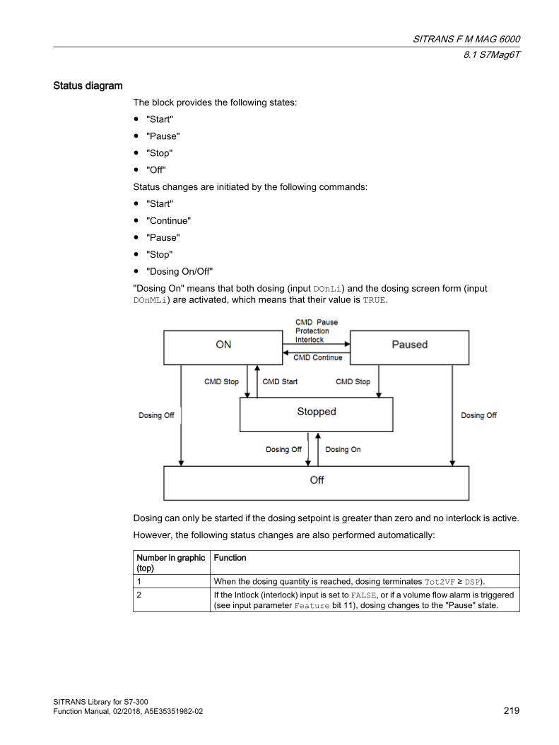
Status diagramThe block provides the following states:
● "Start"
● "Pause"
● "Stop"
● "Off"
Status changes are initiated by the following commands:
● "Start"
● "Continue"
● "Pause"
● "Stop"
● "Dosing On/Off"
"Dosing On" means that both dosing (input DOnLi) and the dosing screen form (input DOnMLi) are activated, which means that their value is TRUE.
Dosing can only be started if the dosing setpoint is greater than zero and no interlock is active.
However, the following status changes are also performed automatically:
Number in graphic (top)
Function
1 When the dosing quantity is reached, dosing terminates Tot2VF ≥ DSP).2 If the Intlock (interlock) input is set to FALSE, or if a volume flow alarm is triggered
(see input parameter Feature bit 11), dosing changes to the "Pause" state.
SITRANS F M MAG 60008.1 S7Mag6T
SITRANS Library for S7-300Function Manual, 02/2018, A5E35351982-02 219

Dosing screen form and Dosing startDosing can only start if the dosing screen form (input DOnMLi) as well as dosing (input DOnLi) are activated. Dosing is not activated if the dosing screen form is not active, regardless of whether or not input DOnLi is set to TRUE. Vice versa, while dosing is active it is not possible to deactivate the dosing screen form by setting input DOnMLi to FALSE.
Resetting the dosing quantityThe dosing quantity (output Tot2VF) is reset automatically at the start of a new dosing operation.
External/internal setpoint specificationThis block provides the standard "Setpoint input - external/internal" function that is described in the APL Online Help. At the S7Mag6T block, the parameter names start with DSP (Dosing SetPoint) instead of SP (SetPoint) as in the APL.
Forcing operating statesThe forcing of operating modes function lets you set the function block into a different operating mode using interconnectable input parameters, regardless of the currently active control. Inputs ForceDSrt, ForceDStp, ForceDPause and ForceDCont force the blocks into the states "Start", "Stop" or "Pause".
The "Pause" state can only be forced if the block is in the "Start" state.
The "Start" state can only be forced while one of the following states are active:
● "Pause"
● "Stop"
A forced start of the dosing unit is not possible in "Off" state.
Block icon: The block icon indicates forced states by means of of a red F and a crossed-out padlock.
Faceplate: An information text on the forced operating state is displayed in the standard view of the faceplate, for example, "Forced stop". This is also indicated by a crossed-out padlock:
InterlocksThis block provides the following interlock:
● Interlock without reset ("Interlock")
Refer to the "Interlocks" chapter in the APL Online Help.
SITRANS F M MAG 60008.1 S7Mag6T
SITRANS Library for S7-300220 Function Manual, 02/2018, A5E35351982-02

Disabling interlocksThis block provides the standard "Deactivate interlocks" function that is described in the APL Online Help.
Note that you need to edit the message texts once again if you install a new block version in your project.
8.1.6 Error handling of S7Mag6T
Error handling of S7Mag6T For general information on error handling at all blocks, refer to the "Error handling" chapter in the APL Online Help.
The following errors can be displayed for this block:
● Error numbers
● Mode switchover error
Overview of error numbers The I/Os Error1Num (Totalizer 1) and Error2Num (Totalizer 2 or dosing unit) can be used to output the following error numbers:
Error number Meaning of the error number-1 Predefined value when inserting the block; the block is not executed.0 There is no error.12 At least one limit is not plausible, for example, because the alarm high limit is
less than the warning high limit41 The value for the I/O LocalSetting is not within the approved limit of 0, 1, or 3.42 LocalSetting = 0 and LocalLi = 1
SITRANS F M MAG 60008.1 S7Mag6T
SITRANS Library for S7-300Function Manual, 02/2018, A5E35351982-02 221

48 DSP_LiOp = 1 and DSP_IntLi = 1 and DSP_ExtLi = 151 AutModLi = 1 and ManModLi = 1 and Feature bit set switch or pushbutton mode
= 0or two I/Os are set at the same time:● In "Local mode":
Totalizer 1 or 2:Bal1Local, Pos1Local, Neg1Local, Hold1Local or Bal2Local, Pos2Local, Neg2Local, Hold2LocalDosing unit:DSrtLocal (pos. edge), DStpLocal, DPauseLocal, DContLocal
With forcing of states:Dosing unit:ForceDSrt, ForceDStp, ForceDPause, ForceDCont
● In "Automatic mode" with pushbutton mode:Totalizer 1 or 2:Bal1Aut, Pos1Aut, Neg1Aut, Hold1Aut or Bal2Aut, Pos2Aut, Neg2Aut, Hold2AutDosing unit:DSrtAut (pos. edge), DStpAut, DContAut, DPauseAut
● In "Manual mode":Totalizer 1 or 2:Bal1Man, Pos1Man, Neg1Man, Hold1Man or Bal2Man, Pos2Man, Neg2Man, Hold2ManDosing unit:DSrtMan, DStpMan, DPauseMan, DContMan
Mode switchover error This error is output if you change the mode of the block from
● Manual to automatic mode or
● Local mode to automatic mode
and the previous state and the target state mismatch (bumpless changeover). You can only change the block mode if the subsequent state corresponds with the previous state.
You can activate/deactivate bumpless changeover by setting bit 17 at the Feature I/O (bumpless changeover to automatic mode).
The bumpless changeover from local to automatic mode is handled by means of the LocalSetting parameter as described in the "Local mode" chapter of the APL Online Help.
In the standard view of the faceplate, the text "Changeover error" is displayed in the event of an unwanted switchover with bumps.
The block retains local mode if the operator changes the mode from local to automatic and the error mentioned above occurs. The block changes to manual mode if the mode is changed from local to automatic over interconnected inputs and the error mentioned above occurs.
See alsoS7Mag6T connections (Page 225)
SITRANS F M MAG 60008.1 S7Mag6T
SITRANS Library for S7-300222 Function Manual, 02/2018, A5E35351982-02
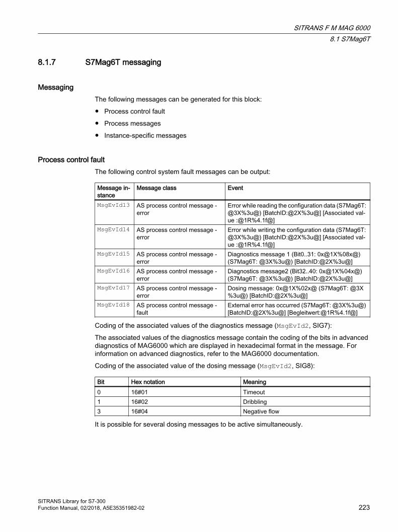
8.1.7 S7Mag6T messaging
Messaging The following messages can be generated for this block:
● Process control fault
● Process messages
● Instance-specific messages
Process control fault The following control system fault messages can be output:
Message in‐stance
Message class Event
MsgEvId13 AS process control message - error
Error while reading the configuration data (S7Mag6T: @3X%3u@) [BatchID:@2X%3u@] [Associated val‐ue :@1R%4.1f@]
MsgEvId14 AS process control message - error
Error while writing the configuration data (S7Mag6T: @3X%3u@) [BatchID:@2X%3u@] [Associated val‐ue :@1R%4.1f@]
MsgEvId15 AS process control message - error
Diagnostics message 1 (Bit0..31: 0x@1X%08x@) (S7Mag6T: @3X%3u@) [BatchID:@2X%3u@]
MsgEvId16 AS process control message - error
Diagnostics message2 (Bit32..40: 0x@1X%04x@) (S7Mag6T: @3X%3u@) [BatchID:@2X%3u@]
MsgEvId17 AS process control message - error
Dosing message: 0x@1X%02x@ (S7Mag6T: @3X%3u@) [BatchID:@2X%3u@]
MsgEvId18 AS process control message - fault
External error has occurred (S7Mag6T: @3X%3u@) [BatchID:@2X%3u@] [Begleitwert:@1R%4.1f@]
Coding of the associated values of the diagnostics message (MsgEvId2, SIG7):
The associated values of the diagnostics message contain the coding of the bits in advanced diagnostics of MAG6000 which are displayed in hexadecimal format in the message. For information on advanced diagnostics, refer to the MAG6000 documentation.
Coding of the associated value of the dosing message (MsgEvId2, SIG8):
Bit Hex notation Meaning0 16#01 Timeout1 16#02 Dribbling3 16#04 Negative flow
It is possible for several dosing messages to be active simultaneously.
SITRANS F M MAG 60008.1 S7Mag6T
SITRANS Library for S7-300Function Manual, 02/2018, A5E35351982-02 223

Process messages
Message in‐stance
Message class Event
MsgEvId01 Alarm - high Volume flow - high alarm limit violated (S7Mag6T: @3X%3u@) [BatchID:@2X%3u@] [Associated val‐ue:@1R%4.1f@]
MsgEvId02 Warning - high Volume flow - high warning limit violated(S7Mag6T: @3X%3u@) [BatchID:@2X%3u@] [Associated val‐ue:@1R%4.1f@]
MsgEvId03 Warning - low Volume flow - low warning limit violated (S7Mag6T: @3X%3u@) [BatchID:@2X%3u@] [Associated val‐ue:@1R%4.1f@]
MsgEvId04 Alarm - low Volume flow - low alarm limit violated (S7Mag6T: @3X%3u@) [BatchID:@2X%3u@] [Associated val‐ue:@1R%4.1f@]
MsgEvId05 Alarm - high Totalizer 1 - High alarm limit violated (S7Mag6T: @3X%3u@) [BatchID:@2X%3u@] [Associated val‐ue:@1R%4.1f@]
MsgEvId06 Warning - high Totalizer 1 - High warning limit violated(S7Mag6T: @3X%3u@) [BatchID:@2X%3u@] [Associated val‐ue:@1R%4.1f@]
MsgEvId07 Warning - low Totalizer 1 -Low warning limit violated(S7Mag6T: @3X%3u@) [BatchID:@2X%3u@] [Associated val‐ue:@1R%4.1f@]
MsgEvId08 Alarm - low Totalizer 1 - Low alarm limit violated(S7Mag6T: @3X%3u@) [BatchID:@2X%3u@] [Associated val‐ue:@1R%4.1f@]
MsgEvId09 Alarm - high Totalizer 2 -High alarm limit violated (S7Mag6T: @3X%3u@) [BatchID:@2X%3u@] [Associated val‐ue:@1R%4.1f@]
MsgEvId10 Warning - high Totalizer 2 - High warning limit violated (S7Mag6T: @3X%3u@) [BatchID:@2X%3u@] [Associated val‐ue:@1R%4.1f@]
MsgEvId11 Warning - low Totalizer 2 - Low warning limit violated (S7Mag6T: @3X%3u@) [BatchID:@2X%3u@] [Associated val‐ue:@1R%4.1f@]
MsgEvId12 Alarm - low Totalizer 2 - Low alarm limit violated (S7Mag6T: @3X%3u@) [BatchID:@2X%3u@] [Associated val‐ue:@1R%4.1f@]
MsgEvId19 Process message - with ac‐knowledgment
Dosing canceled (S7Mag6T: @3X%3u@) [Batch‐ID:@2X%3u@] [Begleitwert:@1R%4.1f@]
SITRANS F M MAG 60008.1 S7Mag6T
SITRANS Library for S7-300224 Function Manual, 02/2018, A5E35351982-02

Associated values for the message instances
Associated val‐ue
Block parameters
1 Aux (MsgEvId15 = MsgAVD1, MsgEvId16= MsgAVD1, MsgEvId17 = MsgAVDos)
2 BatchID3 MsgFilter
8.1.8 S7Mag6T connectionsS7Mag6T connections
Input parameters
Parameter Description Type DefaultDSP_LiOp Dosing unit: Select setpoint
source (internal/external):● 1 = Via interconnection● 0 = Via operator
BOOL 0
DSP_ExtOp Dosing unit: 1 = Select external setpoints via operator
BOOL 0
DSP_IntOp Dosing unit: 1 = Select internal setpoints via operator
BOOL 0
DSP_ExtLi Dosing unit: 1 = Select external setpoints via interconnection
BOOL 0
DSP_IntLi Dosing unit: 1 = Select internal setpoints via interconnection
BOOL 0
SP_TrkExt Dosing unit: 1 = Bumpless switch‐over from external to internal set‐point active
BOOL 1
DSP_Int Dosing unit: Internal setpoint REAL 0.0DSP_Ext Dosing unit: External setpoint REAL 0.0QCDSP_Ext Dosing unit: State of external set‐
pointBYTE 16#80
DSP_HiLim Dosing unit: High limit for dosing quantity
REAL 100.0
DSP_LoLim Dosing unit: Low limit for dosing quantity
REAL 0.0
InVFUnit Unit of measure for volume flow INT 0InTot1Unit Unit of measure for Totalizer 1 INT 0InTot2Unit Unit of measure for Totalizer 2/
dosing quantityINT 0
InVF_Hyst VF - Alarm Hysteresis REAL 0.0InVF_AH_Lim Volume flow alarm (high) limit REAL 0.0
SITRANS F M MAG 60008.1 S7Mag6T
SITRANS Library for S7-300Function Manual, 02/2018, A5E35351982-02 225
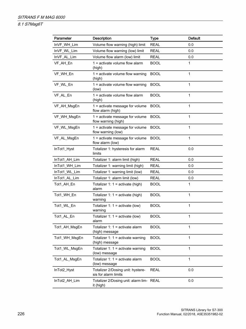
Parameter Description Type DefaultInVF_WH_Lim Volume flow warning (high) limit REAL 0.0InVF_WL_Lim Volume flow warning (low) limit REAL 0.0InVF_AL_Lim Volume flow alarm (low) limit REAL 0.0VF_AH_En 1 = activate volume flow alarm
(high)BOOL 1
VF_WH_En 1 = activate volume flow warning (high)
BOOL 1
VF_WL_En 1 = activate volume flow warning (low)
BOOL 1
VF_AL_En 1 = activate volume flow alarm (high)
BOOL 1
VF_AH_MsgEn 1 = activate message for volume flow alarm (high)
BOOL 1
VF_WH_MsgEn 1 = activate message for volume flow warning (high)
BOOL 1
VF_WL_MsgEn 1 = activate message for volume flow warning (low)
BOOL 1
VF_AL_MsgEn 1 = activate message for volume flow alarm (low)
BOOL 1
InTot1_Hyst Totalizer 1: hysteresis for alarm limits
REAL 0.0
InTot1_AH_Lim Totalizer 1: alarm limit (high) REAL 0.0InTot1_WH_Lim Totalizer 1: warning limit (high) REAL 0.0InTot1_WL_Lim Totalizer 1: warning limit (low) REAL 0.0InTot1_AL_Lim Totalizer 1: alarm limit (low) REAL 0.0Tot1_AH_En Totalizer 1: 1 = activate (high)
alarmBOOL 1
Tot1_WH_En Totalizer 1: 1 = activate (high) warning
BOOL 1
Tot1_WL_En Totalizer 1: 1 = activate (low) warning
BOOL 1
Tot1_AL_En Totalizer 1: 1 = activate (low) alarm
BOOL 1
Tot1_AH_MsgEn Totalizer 1: 1 = activate alarm (high) message
BOOL 1
Tot1_WH_MsgEn Totalizer 1: 1 = activate warning (high) message
BOOL 1
Tot1_WL_MsgEn Totalizer 1: 1 = activate warning (low) message
BOOL 1
Tot1_AL_MsgEn Totalizer 1: 1 = activate alarm (low) message
BOOL 1
InTot2_Hyst Totalizer 2/Dosing unit: hystere‐sis for alarm limits
REAL 0.0
InTot2_AH_Lim Totalizer 2/Dosing unit: alarm lim‐it (high)
REAL 0.0
SITRANS F M MAG 60008.1 S7Mag6T
SITRANS Library for S7-300226 Function Manual, 02/2018, A5E35351982-02

Parameter Description Type DefaultInTot2_WH_Lim Totalizer 2/Dosing unit: warning
limit (high)REAL 0.0
InTot2_WL_Lim Totalizer 2/Dosing unit: warning limit (low)
REAL 0.0
InTot2_AL_Lim Totalizer 2/Dosing unit: alarm lim‐it (low)
REAL 0.0
DosCancelMsgEn Dosing unit: 1 = activate "Dosing aborted" message
BOOL 1
Tot2_AH_En Totalizer 2/Dosing unit: 1 = acti‐vate (high) alarm
BOOL 1
Tot2_WH_En Totalizer 2/Dosing unit: 1 = acti‐vate (high) warning
BOOL 1
Tot2_WL_En Totalizer 2/Dosing unit: 1 = acti‐vate (low) warning
BOOL 1
Tot2_AL_En Totalizer 2/Dosing unit: 1 = acti‐vate (low) alarm
BOOL 1
Tot2_AH_MsgEn Totalizer 2/Dosing unit: 1 = acti‐vate alarm (high) message
BOOL 1
Tot2_WH_MsgEn Totalizer 2/Dosing unit: 1 = acti‐vate warning (high) message
BOOL 1
Tot2_WL_MsgEn Totalizer 2/Dosing unit: 1 = acti‐vate warning (low) message
BOOL 1
Tot2_AL_MsgEn Totalizer 2/Dosing unit: 1 = acti‐vate alarm (low) message
BOOL 1
InVF_OpScaleH Volume flow: High limit for scale of bar display of faceplate
REAL 0.0
InVF_OpScaleL Volume flow: Low limit for scale of bar display of faceplate
REAL 0.0
Bal1Aut Totalizer 1: Up counter for posi‐tive flow and down counter for negative flow in automatic mode
BOOL 0
Pos1Aut Totalizer 1: Increment only with positive flow in auto mode
BOOL 0
Neg1Aut Totalizer 1: Decrement only with negative flow in auto mode
BOOL 0
Hold1Aut Totalizer 1: Stop of the totalizer in automatic mode
BOOL 0
ReTot1Li Totalizer 1: 1 = Reset of the total‐izer via interconnection
BOOL 0
Bal1Man Totalizer 1: Up counter for posi‐tive flow and down counter for negative flow in manual mode
BOOL 0
Pos1Man Totalizer 1: Increment only for positive flow in manual mode
BOOL 0
Neg1Man Totalizer 1: Decrement only for negative flow in manual mode
BOOL 0
Hold1Man Totalizer 1: Stop totalizer in man‐ual mode
BOOL 0
SITRANS F M MAG 60008.1 S7Mag6T
SITRANS Library for S7-300Function Manual, 02/2018, A5E35351982-02 227
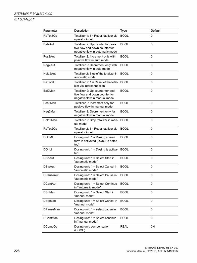
Parameter Description Type DefaultReTot1Op Totalizer 1: 1 = Reset totalizer via
operator inputBOOL 0
Bal2Aut Totalizer 2: Up counter for posi‐tive flow and down counter for negative flow in automatic mode
BOOL 0
Pos2Aut Totalizer 2: Increment only with positive flow in auto mode
BOOL 0
Neg2Aut Totalizer 2: Decrement only with negative flow in auto mode
BOOL 0
Hold2Aut Totalizer 2: Stop of the totalizer in automatic mode
BOOL 0
ReTot2Li Totalizer 2: 1 = Reset of the total‐izer via interconnection
BOOL 0
Bal2Man Totalizer 2: Up counter for posi‐tive flow and down counter for negative flow in manual mode
BOOL 0
Pos2Man Totalizer 2: Increment only for positive flow in manual mode
BOOL 0
Neg2Man Totalizer 2: Decrement only for negative flow in manual mode
BOOL 0
Hold2Man Totalizer 2: Stop totalizer in man‐ual mode
BOOL 0
ReTot2Op Totalizer 2: 1 = Reset totalizer via operator input
BOOL 0
DOnMLi Dosing unit: 1 = Dosing screen form is activated (DOnLi is detec‐ted)
BOOL 0
DOnLi Dosing unit: 1 = Dosing is activa‐ted
BOOL 0
DSrtAut Dosing unit: 1 = Select Start in "automatic mode"
BOOL 0
DStpAut Dosing unit: 1 = Select Cancel in "automatic mode"
BOOL 0
DPauseAut Dosing unit: 1 = Select Pause in "automatic mode"
BOOL 0
DContAut Dosing unit: 1 = Select Continue in "automatic mode"
BOOL 0
DSrtMan Dosing unit: 1 = Select Start in "manual mode"
BOOL 0
DStpMan Dosing unit: 1 = Select Cancel in "manual mode"
BOOL 0
DPauseMan Dosing unit: 1 = select pause in "manual mode"
BOOL 0
DContMan Dosing unit: 1 = Select continue in "manual mode"
BOOL 0
DCompOp Dosing unit: compensation (COMP)
REAL 0.0
SITRANS F M MAG 60008.1 S7Mag6T
SITRANS Library for S7-300228 Function Manual, 02/2018, A5E35351982-02

Parameter Description Type DefaultDCompLoLim Dosing unit: compensation low
limitREAL 0.0
RdCfgOp 1 = read all configuration data from MAG6000
BOOL 0
WrCfgOp 1 = write all configuration data to MAG6000
BOOL 0
InZFlSupp Dosing unit: Low flow cut-off sup‐pression
REAL 0.0
Mod1LiOp Totalizer 1: Switchover of operat‐ing mode between:0 = Operator1 = Interconnection or SFC
BOOL 0
AutMod1Op Totalizer 1: 1 = "Automatic mode" via interconnection or SFC (con‐trolled with Mod1LiOp = 1)
BOOL 0
ManMod1Op Totalizer 1: Switchover of operat‐ing mode between:0 = Operator1 = Interconnection or SFC
BOOL 0
AutMod1Li Totalizer 1: 1 = "Automatic mode" via operator (controlled by Mod1LiOp = 0)
BOOL 0
ManMod1Li Totalizer 1: 1 = "Manual mode" via interconnection or SFC (con‐trolled by Mod1LiOp = 1)
BOOL 0
Local1Li Totalizer 1: 1 = Activate "local mode" via plant signals
BOOL 0
Local1Op Totalizer 1: 1 = "Local mode" via operator
BOOL 0
Mod2LiOp Totalizer 2/Dosing unit: Switch‐over of operating mode between:0 = Operator1 = Interconnection or SFC
BOOL 0
AutMod2Op Totalizer 2/Dosing unit: 1 = "Au‐tomatic mode" via interconnec‐tion or SFC (controlled with Mod2LiOp = 1)
BOOL 0
ManMod2Op Totalizer 2/Dosing unit: Switch‐over of operating mode between:0 = Operator1 = Interconnection or SFC
BOOL 0
AutMod2Li Totalizer 2/Dosing unit: 1 = "Au‐tomatic mode" via operator (con‐trolled by Mod2LiOp = 0)
BOOL 0
ManMod2Li Totalizer 2/Dosing unit: 1 = "Man‐ual mode" via interconnection or SFC (controlled by Mod2LiOp = 1)
BOOL 0
SITRANS F M MAG 60008.1 S7Mag6T
SITRANS Library for S7-300Function Manual, 02/2018, A5E35351982-02 229
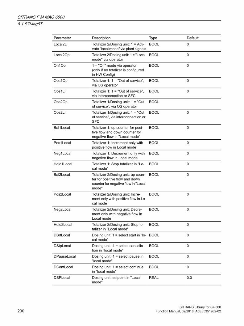
Parameter Description Type DefaultLocal2Li Totalizer 2/Dosing unit: 1 = Acti‐
vate "local mode" via plant signalsBOOL 0
Local2Op Totalizer 2/Dosing unit: 1 = "Local mode" via operator
BOOL 0
On1Op 1 = "On" mode via operator(only if no totalizer is configured in HW Config)
BOOL 0
Oos1Op Totalizer 1: 1 = "Out of service", via OS operator
BOOL 0
Oos1Li Totalizer 1: 1 = "Out of service", via interconnection or SFC
BOOL 0
Oos2Op Totalizer 1/Dosing unit: 1 = "Out of service", via OS operator
BOOL
Oos2Li Totalizer 1/Dosing unit: 1 = "Out of service", via interconnection or SFC
BOOL 0
Bal1Local Totalizer 1: up counter for posi‐tive flow and down counter for negative flow in "Local mode"
BOOL 0
Pos1Local Totalizer 1: Increment only with positive flow in Local mode
BOOL 0
Neg1Local Totalizer 1: Decrement only with negative flow in Local mode
BOOL 0
Hold1Local Totalizer 1: Stop totalizer in "Lo‐cal mode"
BOOL 0
Bal2Local Totalizer 2/Dosing unit: up coun‐ter for positive flow and down counter for negative flow in "Local mode"
BOOL 0
Pos2Local Totalizer 2/Dosing unit: Incre‐ment only with positive flow in Lo‐cal mode
BOOL 0
Neg2Local Totalizer 2/Dosing unit: Decre‐ment only with negative flow in Local mode
BOOL 0
Hold2Local Totalizer 2/Dosing unit: Stop to‐talizer in "Local mode"
BOOL 0
DSrtLocal Dosing unit: 1 = select start in "lo‐cal mode"
BOOL 0
DStpLocal Dosing unit: 1 = select cancella‐tion in "local mode"
BOOL 0
DPauseLocal Dosing unit: 1 = select pause in "local mode"
BOOL 0
DContLocal Dosing unit: 1 = select continue in "local mode"
BOOL 0
DSPLocal Dosing unit: setpoint in "Local mode"
REAL 0.0
SITRANS F M MAG 60008.1 S7Mag6T
SITRANS Library for S7-300230 Function Manual, 02/2018, A5E35351982-02

Parameter Description Type DefaultLocalSetting "Local mode" properties (see "Lo‐
cal mode" in the APL Online Help)INT 0
Intlock 0 = Interlock of the dosing unit without reset is active; you can operate the block without reset once the interlock condition has been cleared1 = interlock of the dosing unit not activated
BOOL 1
Intl_En 1 = interlock of the dosing unit without reset (interlock, parame‐ter Intlock) is active
BOOL 1
ForceDSrt Dosing unit: 1 = Forced start BOOL 0ForceDStp Dosing unit: 1 = force stop BOOL 0ForceDPause Dosing unit: 1 = Force pause BOOL 0ForceDCont Dosing unit: 1 = force continue BOOL 0MsgLock 1 = Suppress process messages.
For more information, refer to the "Suppressing messages by means of parameter MsgLock" chapter in the APL Online Help
BOOL 0
RunUpCyc Number of cycles in startup; mes‐sages are suppressed during these cycles
INT 3
MsgEvId01.. 19 Message number (assigned auto‐matically)
DWORD 16#00000000
Aux Message associated value REAL 0.0BatchEn 1 = Enable allocation BOOL 0BatchID Batch ID DWORD 16#00000000BatchName Batch name S7-String StepNo Batch step number DWORD 16#00000000Occupied 1 = In use by a batch BOOL 0MsgFilter Message filter DINT 0CmpID component identifier (not permis‐
sible: 0)Identification of the subsystem to which the message is assigned toRecommended values:● low word: 1 to 65535● high word: 0
DWORD 16#00000001
PERMIS Switchover of the operator con‐trol permission
INT 2
SITRANS F M MAG 60008.1 S7Mag6T
SITRANS Library for S7-300Function Manual, 02/2018, A5E35351982-02 231
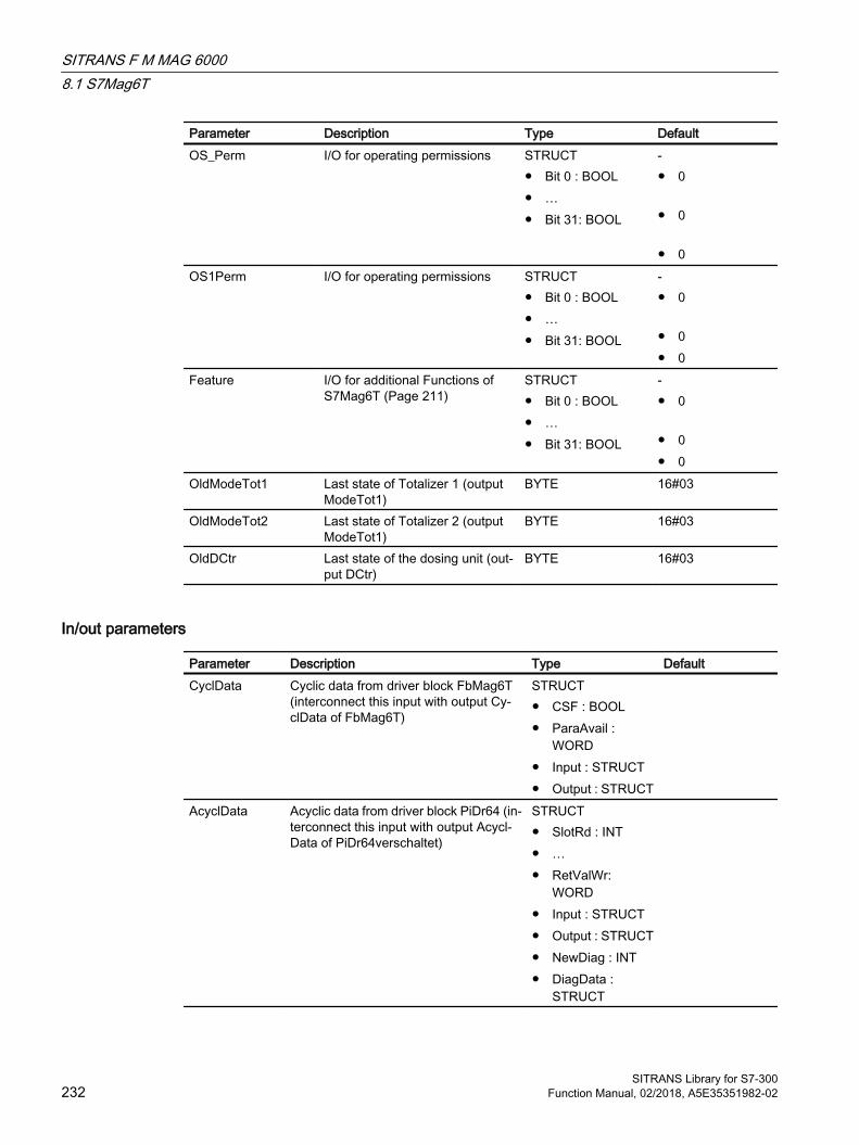
Parameter Description Type DefaultOS_Perm I/O for operating permissions STRUCT
● Bit 0 : BOOL● …● Bit 31: BOOL
-● 0
● 0
● 0OS1Perm I/O for operating permissions STRUCT
● Bit 0 : BOOL● …● Bit 31: BOOL
-● 0
● 0● 0
Feature I/O for additional Functions of S7Mag6T (Page 211)
STRUCT● Bit 0 : BOOL● …● Bit 31: BOOL
-● 0
● 0● 0
OldModeTot1 Last state of Totalizer 1 (output ModeTot1)
BYTE 16#03
OldModeTot2 Last state of Totalizer 2 (output ModeTot1)
BYTE 16#03
OldDCtr Last state of the dosing unit (out‐put DCtr)
BYTE 16#03
In/out parameters
Parameter Description Type DefaultCyclData Cyclic data from driver block FbMag6T
(interconnect this input with output Cy‐clData of FbMag6T)
STRUCT● CSF : BOOL● ParaAvail :
WORD● Input : STRUCT● Output : STRUCT
AcyclData Acyclic data from driver block PiDr64 (in‐terconnect this input with output Acycl‐Data of PiDr64verschaltet)
STRUCT● SlotRd : INT● …● RetValWr:
WORD● Input : STRUCT● Output : STRUCT● NewDiag : INT● DiagData :
STRUCT
SITRANS F M MAG 60008.1 S7Mag6T
SITRANS Library for S7-300232 Function Manual, 02/2018, A5E35351982-02

Output parameters
Parameter Description Type DefaultSetTot1 Totalizer 1: 16#01 = reset command out‐
put to the module (SET_TOT from HW Config)
BYTE 16#00
ModeTot1 ● Totalizer 1: Command transferred to the module (MODE_TOT from HW Config):
● ü16#00: up counter for positive flow and down counter for negative flow in manual mode
● ü16#01: only up counter with positive flow
● ü16#02: only down counter with negative flow
● ü16#03: Stop totalizer
BYTE 16#03
SetTot2 Totalizer 2: 16#01 = reset command out‐put to the module (SET_TOT from HW Config)
BYTE 16#00
ModeTot2 ● Totalizer 1: Command transferred to the module (MODE_TOT from HW Config):
● 16#00 : up counter for positive flow and down counter for negative flow in manual mode
● 16#01: only up counter with positive flow
● 16#02: only down counter with negative flow
● 16#03: Stop totalizer
BYTE 16#03
DCtr ● Dosing unit: Command transferred to the module (B_CTR from HW Config):
● Bit 0: 1 = start dosing● Bit 1: 1 = stop dosing● Bit 2: 1 = update setpoint and
compensation● Bit 3: 1 = enable dosing● Bit 4: 1 = enable dosing screen form● Bit 5: 1 = set dosing pause● Bit 6: 1 = resume dosing
BYTE 16#00
DStr ● 1= start dosing BOOL 0DStp ● 1= stop dosing BOOL 0DPause ● 1 = set dosing unit pause BOOL 0
SITRANS F M MAG 60008.1 S7Mag6T
SITRANS Library for S7-300Function Manual, 02/2018, A5E35351982-02 233
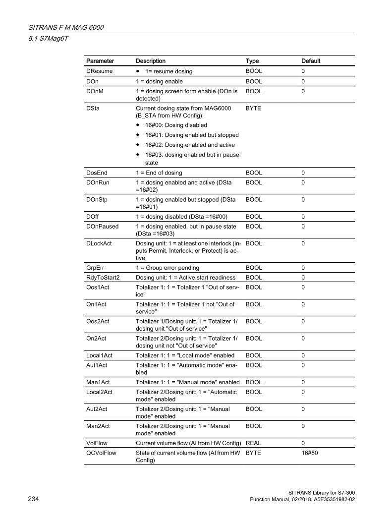
Parameter Description Type DefaultDResume ● 1= resume dosing BOOL 0DOn 1 = dosing enable BOOL 0DOnM 1 = dosing screen form enable (DOn is
detected)BOOL 0
DSta Current dosing state from MAG6000 (B_STA from HW Config):● 16#00: Dosing disabled● 16#01: Dosing enabled but stopped● 16#02: Dosing enabled and active● 16#03: dosing enabled but in pause
state
BYTE
DosEnd 1 = End of dosing BOOL 0DOnRun 1 = dosing enabled and active (DSta
=16#02)BOOL 0
DOnStp 1 = dosing enabled but stopped (DSta =16#01)
BOOL 0
DOff 1 = dosing disabled (DSta =16#00) BOOL 0DOnPaused 1 = dosing enabled, but in pause state
(DSta =16#03)BOOL 0
DLockAct Dosing unit: 1 = at least one interlock (in‐puts Permit, Interlock, or Protect) is ac‐tive
BOOL 0
GrpErr 1 = Group error pending BOOL 0RdyToStart2 Dosing unit: 1 = Active start readiness BOOL 0Oos1Act Totalizer 1: 1 = Totalizer 1 "Out of serv‐
ice"BOOL 0
On1Act Totalizer 1: 1 = Totalizer 1 not "Out of service"
BOOL 0
Oos2Act Totalizer 1/Dosing unit: 1 = Totalizer 1/dosing unit "Out of service"
BOOL 0
On2Act Totalizer 2/Dosing unit: 1 = Totalizer 1/dosing unit not "Out of service"
BOOL 0
Local1Act Totalizer 1: 1 = "Local mode" enabled BOOL 0Aut1Act Totalizer 1: 1 = "Automatic mode" ena‐
bledBOOL 0
Man1Act Totalizer 1: 1 = "Manual mode" enabled BOOL 0Local2Act Totalizer 2/Dosing unit: 1 = "Automatic
mode" enabledBOOL 0
Aut2Act Totalizer 2/Dosing unit: 1 = "Manual mode" enabled
BOOL 0
Man2Act Totalizer 2/Dosing unit: 1 = "Manual mode" enabled
BOOL 0
VolFlow Current volume flow (AI from HW Config) REAL 0QCVolFlow State of current volume flow (AI from HW
Config)BYTE 16#80
SITRANS F M MAG 60008.1 S7Mag6T
SITRANS Library for S7-300234 Function Manual, 02/2018, A5E35351982-02
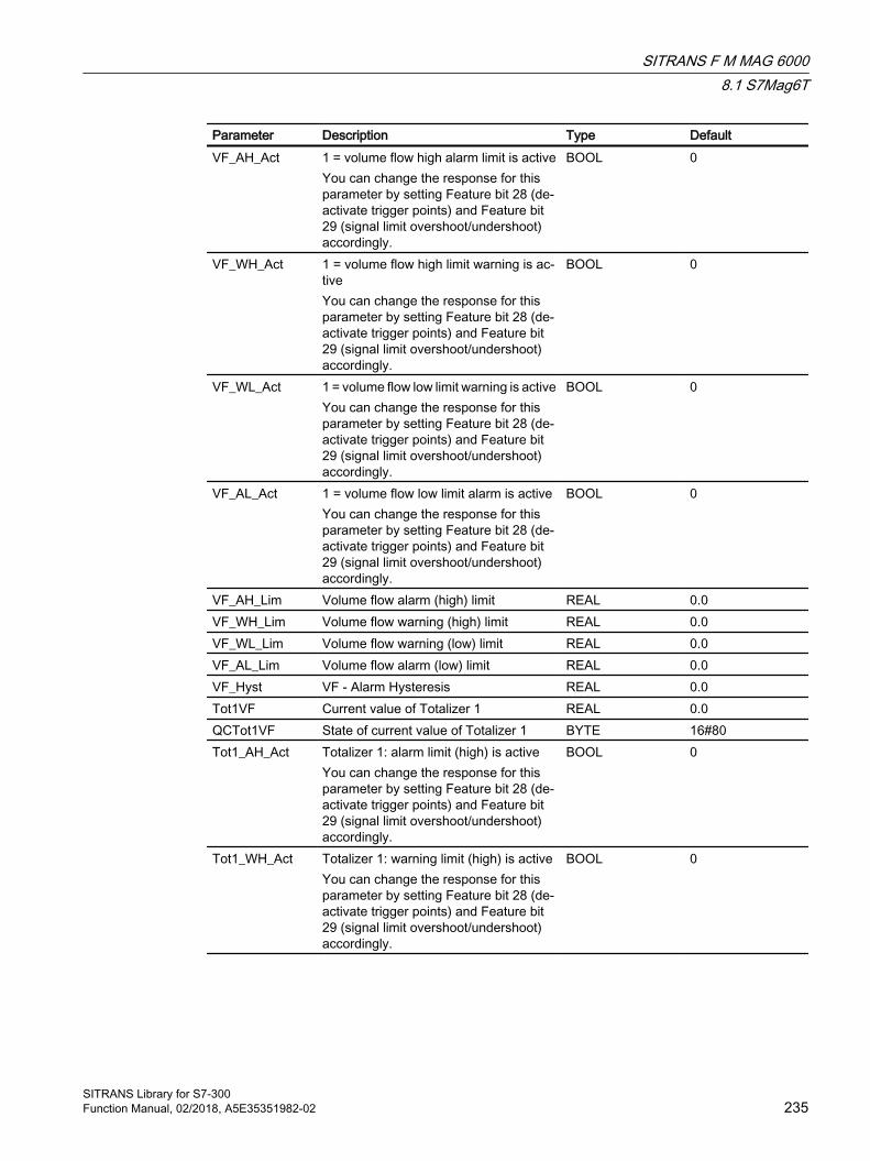
Parameter Description Type DefaultVF_AH_Act 1 = volume flow high alarm limit is active
You can change the response for this parameter by setting Feature bit 28 (de‐activate trigger points) and Feature bit 29 (signal limit overshoot/undershoot) accordingly.
BOOL 0
VF_WH_Act 1 = volume flow high limit warning is ac‐tiveYou can change the response for this parameter by setting Feature bit 28 (de‐activate trigger points) and Feature bit 29 (signal limit overshoot/undershoot) accordingly.
BOOL 0
VF_WL_Act 1 = volume flow low limit warning is activeYou can change the response for this parameter by setting Feature bit 28 (de‐activate trigger points) and Feature bit 29 (signal limit overshoot/undershoot) accordingly.
BOOL 0
VF_AL_Act 1 = volume flow low limit alarm is activeYou can change the response for this parameter by setting Feature bit 28 (de‐activate trigger points) and Feature bit 29 (signal limit overshoot/undershoot) accordingly.
BOOL 0
VF_AH_Lim Volume flow alarm (high) limit REAL 0.0VF_WH_Lim Volume flow warning (high) limit REAL 0.0VF_WL_Lim Volume flow warning (low) limit REAL 0.0VF_AL_Lim Volume flow alarm (low) limit REAL 0.0VF_Hyst VF - Alarm Hysteresis REAL 0.0Tot1VF Current value of Totalizer 1 REAL 0.0QCTot1VF State of current value of Totalizer 1 BYTE 16#80Tot1_AH_Act Totalizer 1: alarm limit (high) is active
You can change the response for this parameter by setting Feature bit 28 (de‐activate trigger points) and Feature bit 29 (signal limit overshoot/undershoot) accordingly.
BOOL 0
Tot1_WH_Act Totalizer 1: warning limit (high) is activeYou can change the response for this parameter by setting Feature bit 28 (de‐activate trigger points) and Feature bit 29 (signal limit overshoot/undershoot) accordingly.
BOOL 0
SITRANS F M MAG 60008.1 S7Mag6T
SITRANS Library for S7-300Function Manual, 02/2018, A5E35351982-02 235
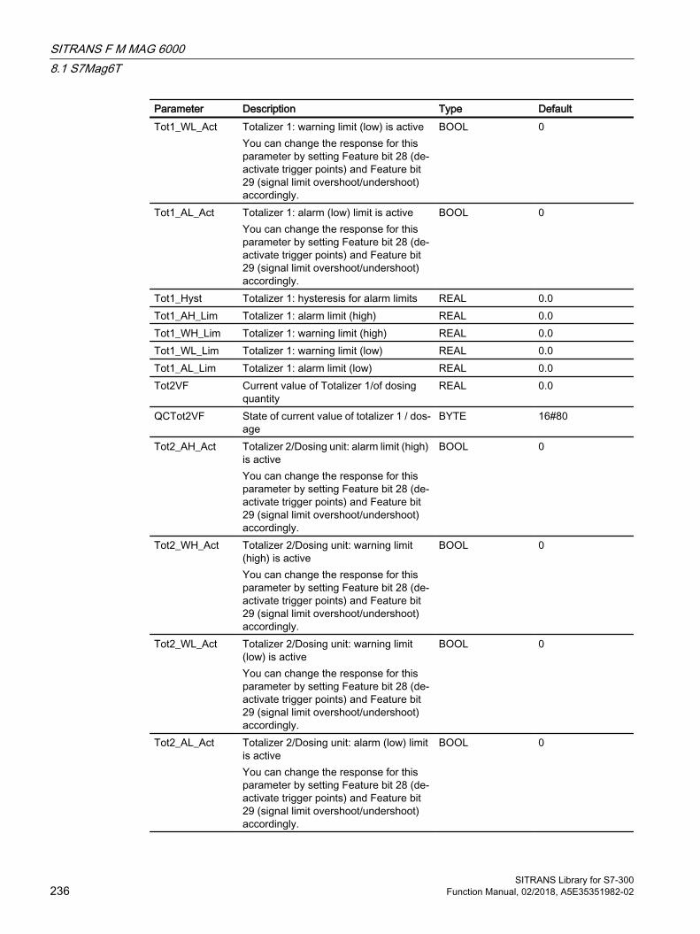
Parameter Description Type DefaultTot1_WL_Act Totalizer 1: warning limit (low) is active
You can change the response for this parameter by setting Feature bit 28 (de‐activate trigger points) and Feature bit 29 (signal limit overshoot/undershoot) accordingly.
BOOL 0
Tot1_AL_Act Totalizer 1: alarm (low) limit is activeYou can change the response for this parameter by setting Feature bit 28 (de‐activate trigger points) and Feature bit 29 (signal limit overshoot/undershoot) accordingly.
BOOL 0
Tot1_Hyst Totalizer 1: hysteresis for alarm limits REAL 0.0Tot1_AH_Lim Totalizer 1: alarm limit (high) REAL 0.0Tot1_WH_Lim Totalizer 1: warning limit (high) REAL 0.0Tot1_WL_Lim Totalizer 1: warning limit (low) REAL 0.0Tot1_AL_Lim Totalizer 1: alarm limit (low) REAL 0.0Tot2VF Current value of Totalizer 1/of dosing
quantityREAL 0.0
QCTot2VF State of current value of totalizer 1 / dos‐age
BYTE 16#80
Tot2_AH_Act Totalizer 2/Dosing unit: alarm limit (high) is activeYou can change the response for this parameter by setting Feature bit 28 (de‐activate trigger points) and Feature bit 29 (signal limit overshoot/undershoot) accordingly.
BOOL 0
Tot2_WH_Act Totalizer 2/Dosing unit: warning limit (high) is activeYou can change the response for this parameter by setting Feature bit 28 (de‐activate trigger points) and Feature bit 29 (signal limit overshoot/undershoot) accordingly.
BOOL 0
Tot2_WL_Act Totalizer 2/Dosing unit: warning limit (low) is activeYou can change the response for this parameter by setting Feature bit 28 (de‐activate trigger points) and Feature bit 29 (signal limit overshoot/undershoot) accordingly.
BOOL 0
Tot2_AL_Act Totalizer 2/Dosing unit: alarm (low) limit is activeYou can change the response for this parameter by setting Feature bit 28 (de‐activate trigger points) and Feature bit 29 (signal limit overshoot/undershoot) accordingly.
BOOL 0
SITRANS F M MAG 60008.1 S7Mag6T
SITRANS Library for S7-300236 Function Manual, 02/2018, A5E35351982-02

Parameter Description Type DefaultTot2_Hyst Totalizer 1/Dosing unit: hysteresis for
alarm limitsREAL 0.0
Tot2_AH_Lim Totalizer 2/Dosing unit: alarm limit (high) REAL 0.0Tot2_WH_Lim Totalizer 2/Dosing unit: warning limit
(high)REAL 0.0
Tot2_WL_Lim Totalizer 2/Dosing unit: warning limit (low)
REAL 0.0
Tot2_AL_Lim Totalizer 2/Dosing unit: alarm limit (low) REAL 0.0DSP Active setpoint for the dosing unit REAL 0.0QCDSP State of current setpoint of dosing unit BYTE 16#80DSP_ExtAct 1 = external dosing setpoint is active
0 = internal dosing setpoint is activeBOOL 0
DSP_ExtOut External dosing setpoint; corresponds to input parameter DSP_Ext, limited by DSP_LoLim and DSP_HiLim
REAL 0.0
QCDSP_ExtOut State of external setpoint dosing unit BYTE 16#80DSP_ExHiAct Dosing unit:
1 = High limit for external setpoint has been reached
BOOL 0
DSP_ExLoAct Dosing unit:1 = Low limit for external setpoint has been reached
BOOL 0
Status1 Status word 1 DWORD 16#00000000Status2 Status word 2 DWORD 16#00000000Status3 Status word 3 DWORD 16#00000000Status4 Status word 4 DWORD 16#00000000Status5 Status word 5 DWORD 16#00000000Error1Num Totalizer 1: Output of current error num‐
ber. For error numbers that can be out‐put by this block, see Error handling of S7Mag6T (Page 221)
INT -1
Error2Num Totalizer 1/Dosing unit: Output of current error number. For error numbers that can be output by this block, see Error handling of S7Mag6T (Page 221)
INT -1
OS_PermOut Displays of OS_Perm DWORD 16#ffffffffOS_PermLog Display of OS_Perm with settings
changed by the block algorithmDWORD 16#ffffffff
OS1PermOut Display of OS1Perm DWORD 16#ffffffffOS1PermLog Display of OS1Perm with settings
changed by the block algorithmDWORD 16#ffffffff
OpSt_Out Value of the input parameter OpSt_In, for further interconnection with other blocks. Bit 31 of this parameter is used by Feature bit 24
DWORD 16#00000000
ST_Worst Worst signal status BYTE 16#00
SITRANS F M MAG 60008.1 S7Mag6T
SITRANS Library for S7-300Function Manual, 02/2018, A5E35351982-02 237
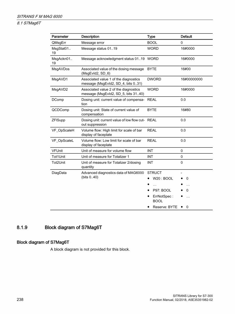
Parameter Description Type DefaultQMsgErr Message error BOOL 0MsgStat01..19
Message status 01..19 WORD 16#0000
MsgAckn01..19
Message acknowledgment status 01..19 WORD 16#0000
MsgAVDos Associated value of the dosing message (MsgEvId2, SD_6)
BYTE 16#00
MsgAVD1 Associated value 1 of the diagnostics message (MsgEvId2, SD_4, bits 0..31)
DWORD 16#00000000
MsgAVD2 Associated value 2 of the diagnostics message (MsgEvId2, SD_5, bits 31..40)
WORD 16#0000
DComp Dosing unit: current value of compensa‐tion
REAL 0.0
QCDComp Dosing unit: State of current value of compensation
BYTE 16#80
ZFlSupp Dosing unit: current value of low flow cut-out suppression
REAL 0.0
VF_OpScaleH Volume flow: High limit for scale of bar display of faceplate
REAL 0.0
VF_OpScaleL Volume flow: Low limit for scale of bar display of faceplate
REAL 0.0
VFUnit Unit of measure for volume flow INT 0Tot1Unit Unit of measure for Totalizer 1 INT 0Tot2Unit Unit of measure for Totalizer 2/dosing
quantityINT 0
DiagData Advanced diagnostics data of MAG6000 (bits 0..40)
STRUCT● W20 : BOOL● …● P97: BOOL● ErrNotSpec :
BOOL● Reserve: BYTE
-● 0● …● 0● …
● 0
8.1.9 Block diagram of S7Mag6T
Block diagram of S7Mag6TA block diagram is not provided for this block.
SITRANS F M MAG 60008.1 S7Mag6T
SITRANS Library for S7-300238 Function Manual, 02/2018, A5E35351982-02

8.1.10 Template of S7Mag6T
Template of S7Mag6TThis process tag type is used to connect a MAG6000 with the driver blocks to PCS 7.
The cyclic values are transferred to and from the device with FbMag6T, while non-cyclic data is transferred with PiDr64.
The process tag type contains the required interconnections between the blocks mentioned above.
To instantiate the template, you must parameterize the volume flow address from the MAG6000 configuration at the inputs of the FbMag6T block (CyclicData) and of the PiDr64 block (AcyclicData) in HW Config as follows:
FbMag6T
Parameter AddressingAVolFlow Volume flow input address (AI)Addr.Tot1 Input address Totalizer 1 (TOTAL, slot 2)Addr.SetTot1 Output address Reset Totalizer 1 (SET_TOT, slot 2)Addr.ModeTot1 Output address command Totalizer 1 (MODE_TOT, slot 2)Addr.Tot2 Input address Totalizer 2/dosing value (TOTAL, slot 3)Addr.SetTot2 Output address Reset Totalizer 2 (SET_TOT, slot 3)Addr.ModeTot2 Output address command Totalizer 2 (MODE_TOT, slot 3)Addr.DCtr Output address control byte (MODE_TOT, slot 3)Addr.DSta Input address dosing unit status (B_STA, slot 3)Addr.DSetP Output address dosing setpoint (SETP, slot 3)Addr.DComp Output address dosing unit compensation (SETP, slot 3)
The length of the elements have to be considered when the right address is selected.
Example:
Resultant configurations at block FbMag6T:
SITRANS F M MAG 60008.1 S7Mag6T
SITRANS Library for S7-300Function Manual, 02/2018, A5E35351982-02 239
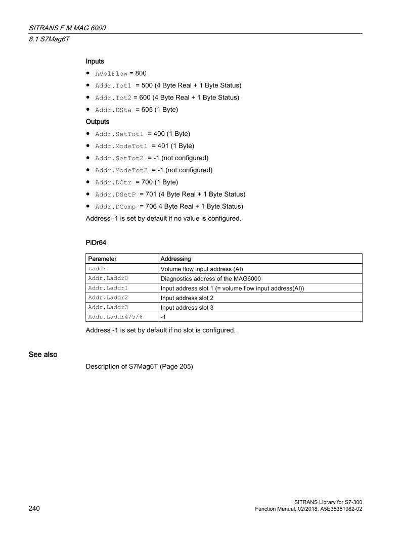
Inputs
● AVolFlow = 800
● Addr.Tot1 = 500 (4 Byte Real + 1 Byte Status)
● Addr.Tot2 = 600 (4 Byte Real + 1 Byte Status)
● Addr.DSta = 605 (1 Byte)
Outputs
● Addr.SetTot1 = 400 (1 Byte)
● Addr.ModeTot1 = 401 (1 Byte)
● Addr.SetTot2 = -1 (not configured)
● Addr.ModeTot2 = -1 (not configured)
● Addr.DCtr = 700 (1 Byte)
● Addr.DSetP = 701 (4 Byte Real + 1 Byte Status)
● Addr.DComp = 706 4 Byte Real + 1 Byte Status)
Address -1 is set by default if no value is configured.
PiDr64
Parameter AddressingLaddr Volume flow input address (AI)Addr.Laddr0 Diagnostics address of the MAG6000Addr.Laddr1 Input address slot 1 (= volume flow input address(AI))Addr.Laddr2 Input address slot 2Addr.Laddr3 Input address slot 3Addr.Laddr4/5/6 -1
Address -1 is set by default if no slot is configured.
See alsoDescription of S7Mag6T (Page 205)
SITRANS F M MAG 60008.1 S7Mag6T
SITRANS Library for S7-300240 Function Manual, 02/2018, A5E35351982-02
8.1.11 Operator control and monitoring
8.1.11.1 S7Mag6T views
Views of the S7Mag6T blockThe S7Mag6T block provides the following views:
● Standard view of S7Mag6T (Page 241)
● Message view (see the APL Online Help)
● Limit view of S7Mag6T (Page 246)
● Trend view (see the APL Online Help)
● Parameter view of S7Mag6T (Page 248)
● S7Mag6T preview (Page 249)
● Memo view (see the APL Online Help)
● Batch view (see the APL Online Help)
● S7Mag6T dosing view (Page 252)
● Block icon for S7Mag6T (Page 254)
For general information on the faceplate and block icon, refer to the sections "Faceplate structure" and "Block icon structure" in the APL Online Help.
8.1.11.2 Standard view of S7Mag6T
Standard view of S7Mag6T Depending on the MAG6000 configuration in HW Config, the standard view displays the elements of Totalizer 1, or of Totalizers 1 and 2, or of Totalizer 1 and the dosing unit. The following two screenshots illustrate the standard view, one showing both totalizers, and the other showing Totalizer 1 and the dosing unit.
Totalizer 1 and Totalizer 2
SITRANS F M MAG 60008.1 S7Mag6T
SITRANS Library for S7-300Function Manual, 02/2018, A5E35351982-02 241

Totalizer 1/Dosing unit
SITRANS F M MAG 60008.1 S7Mag6T
SITRANS Library for S7-300242 Function Manual, 02/2018, A5E35351982-02

(1), (4) and (7) Display and switch the operating modeThis area provides information on the currently valid operating mode. The following operating modes can be shown here:
● Manual mode (see the APL Online Help)
● Automatic mode (see the APL Online Help)
● Local mode (see the APL Online Help)
● Out of service (see APL Online Help)
Totalizers 1 and 2, or the dosing unit are assigned independent, separate operating modes. The block parameters that you need for the respective operating mode are identified by the numbers 1 (Totalizer 1) or 2 (Totalizer 2, or dosing unit), e.g. Mod1LiOp or Oos2Act.
For more information on operating mode changeover, refer to the "Changeover of the operating state and operating mode" in the APL Online Help.
(2) and (5) Display and change the totalizer state: positive and negative, positive, negative and HoldThis area shows you the default operating state for the totalizers. The following states can be shown and executed here:
● "Balanced"
● "Positive"
● "Negative"
● "Hold"
(3) and (6) Resetting the totalizersReset the count value to zero in this area.
(8) Displaying and changing the setpoint of the dosing unitThe following states can be shown and changed here:
● "Internal"
● "External"
(9) Displaying and changing the dosing unit: Start, Resume, Pause, and StopThis area shows you the default operating state for the dosing unit. The following states can be shown and changed here:
● "Start"
● "Continue"
● "Pause"
● "Stop"
SITRANS F M MAG 60008.1 S7Mag6T
SITRANS Library for S7-300Function Manual, 02/2018, A5E35351982-02 243
(10) and (12) High and low scale range for the process valueThese values provide information on the display range for the bar graph of the process value. The scaling range is set by means of PDM in MAG6000 and read by the function block as part of the configuration data.
(11) Display of the volume flow including signal statusThis area displays the current volume flow and the associated signal state.
(13) and (14) Display of the count value, or of the metered quantityThis area displays the current count value of Totalizer 1 or 2, or the metered quantity.
(15)Displaying and changing the setpointThe dosing quantity can only be reset in the "End" status.
(16) Display area for block statesThis area provides additional information on the operating state of the block:
● "Invalid signal"
● "Changeover error"
(17) Display area for dosing unit statesThis area provides additional information on the operating state of the block:
● "Forced start"
● "Force resume"
● "Force pause"
● "Force abort"
● "Request 0/1": A reset to "automatic mode" is expected.
(18) Display area for dosing unit statesThis area provides additional information on the operating state of the dosing unit:
● "End"
(19) Display area for switch permissionThis area provides the text of the current OS, according to the enumeration configured at the PERMIS input.
SITRANS F M MAG 60008.1 S7Mag6T
SITRANS Library for S7-300244 Function Manual, 02/2018, A5E35351982-02

(20) and (22) Limit display for volume flowThese triangles show the VF_AH_Lim/VF_WH_Lim and VF_AL_Lim/VF_WL_Lim limits for the volume flow configured in the MAG6000.
(21) Bar graph for the volume flowThis area shows you a bar graph that visualizes the current volume flow. The visible area in the bar graph depends on the measurement range you configured in MAG6000.
See alsoS7Mag6T views (Page 241)
SITRANS F M MAG 60008.1 S7Mag6T
SITRANS Library for S7-300Function Manual, 02/2018, A5E35351982-02 245
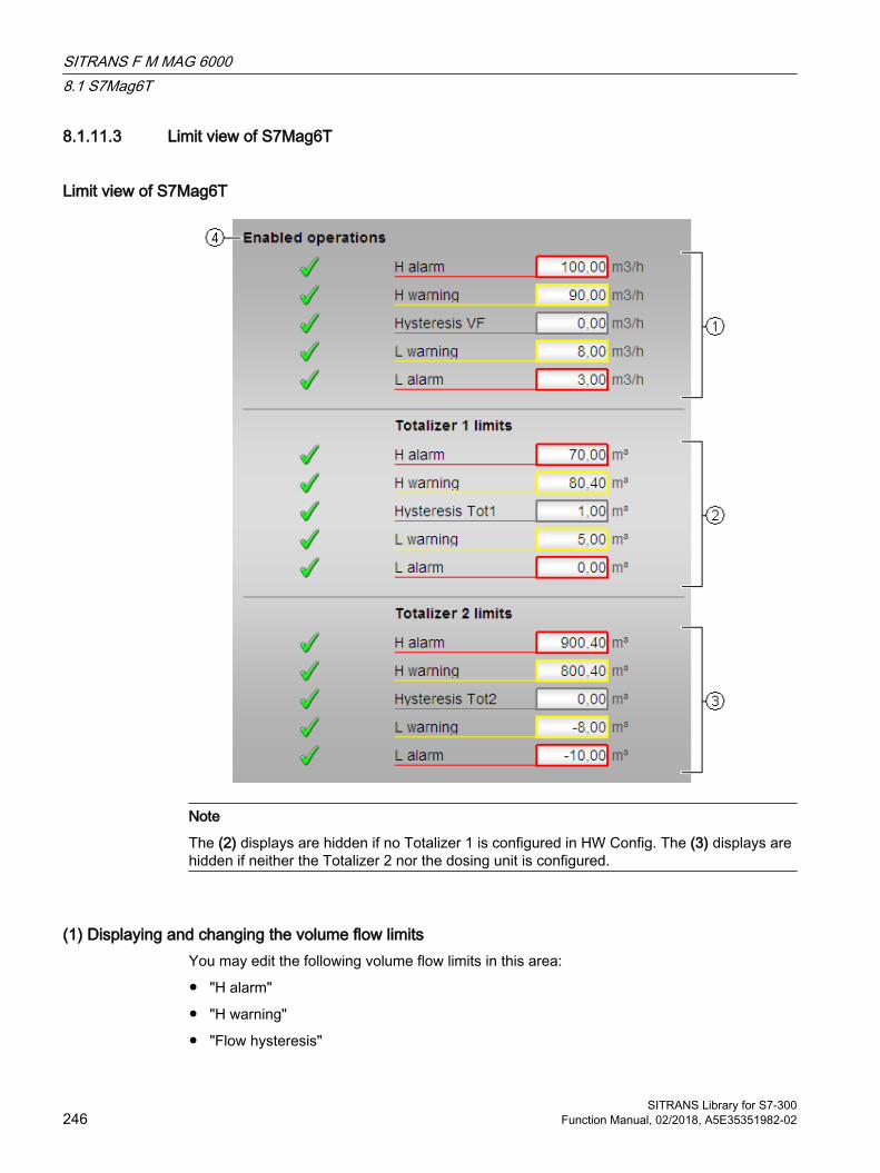
8.1.11.3 Limit view of S7Mag6T
Limit view of S7Mag6T
Note
The (2) displays are hidden if no Totalizer 1 is configured in HW Config. The (3) displays are hidden if neither the Totalizer 2 nor the dosing unit is configured.
(1) Displaying and changing the volume flow limitsYou may edit the following volume flow limits in this area:
● "H alarm"
● "H warning"
● "Flow hysteresis"
SITRANS F M MAG 60008.1 S7Mag6T
SITRANS Library for S7-300246 Function Manual, 02/2018, A5E35351982-02
● “L warning”
● “L alarm”
(2) Displaying and changing the totalizer 1 limitsYou may edit the following Totalizer 1 limits in this area:
● "H alarm"
● "H warning"
● "Totalizer 1 hysteresis"
● “L warning”
● “L alarm”
(3)Displaying and changing the totalizer 2 limitsYou may edit the following Totalizer 2 limits in this area:
● "H alarm"
● "H warning"
● "Totalizer 2 hysteresis"
● “L warning”
● “L alarm”
(4) Enabled operationsThis area shows all operations for which special operator control permissions are assigned. They depend on the configuration in the engineering system (ES) that applies to this block.
Symbols for enabled operations:
● Green check mark: the OS operator can control this parameter
● Gray check mark: the OS operator cannot control this parameter at this time due to the process
● Red cross: the OS operator cannot control this parameter due to the configured AS operator permissions (OS_Perm or OS1Perm)
See alsoS7Mag6T views (Page 241)
SITRANS F M MAG 60008.1 S7Mag6T
SITRANS Library for S7-300Function Manual, 02/2018, A5E35351982-02 247

8.1.11.4 Parameter view of S7Mag6T
Parameter view of S7Mag6T
(1) Read/write configuration dataThis area lets you read all configuration data from your MAG6000, or transfer all configuration data from the block to MAG6000.
(2) ParameterThis area allows you to edit parameters and therefore manipulate the module settings. The compensation is only displayed if you configured the dosing unit in HW Config.
You can influence the following parameters:
● "Zero flow"
● "Compensation"
(3) Enabled operationsThis area shows all operations for which special operator control permissions are assigned. They depend on the configuration in the engineering system (ES) that applies to this block.
Symbols for enabled operations:
● Green check mark: the OS operator can control this parameter
● Gray check mark: the OS operator cannot control this parameter at this time due to the process
● Red cross: the OS operator cannot control this parameter due to the configured AS operator control permissions (OS_Perm or OS1Perm).
See alsoS7Mag6T views (Page 241)
SITRANS F M MAG 60008.1 S7Mag6T
SITRANS Library for S7-300248 Function Manual, 02/2018, A5E35351982-02
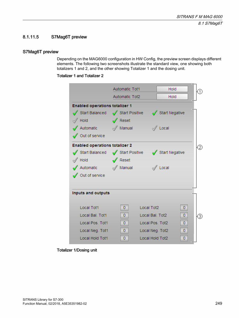
8.1.11.5 S7Mag6T preview
S7Mag6T preview Depending on the MAG6000 configuration in HW Config, the preview screen displays different elements. The following two screenshots illustrate the standard view, one showing both totalizers 1 and 2, and the other showing Totalizer 1 and the dosing unit.
Totalizer 1 and Totalizer 2
Totalizer 1/Dosing unit
SITRANS F M MAG 60008.1 S7Mag6T
SITRANS Library for S7-300Function Manual, 02/2018, A5E35351982-02 249
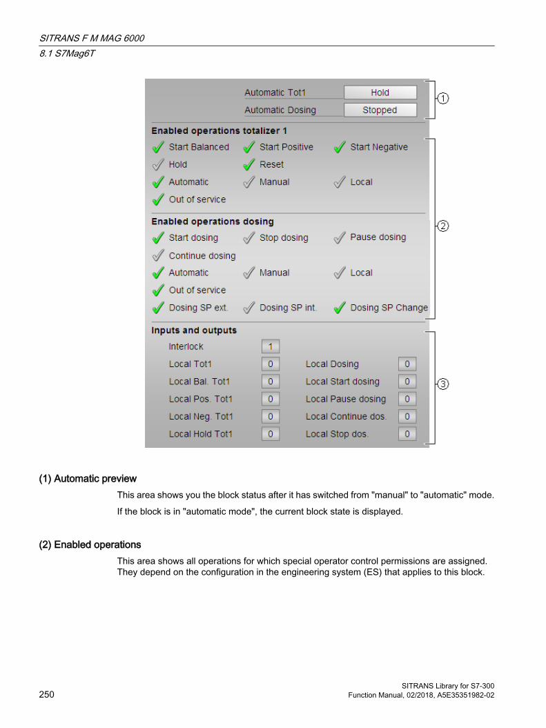
(1) Automatic previewThis area shows you the block status after it has switched from "manual" to "automatic" mode.
If the block is in "automatic mode", the current block state is displayed.
(2) Enabled operationsThis area shows all operations for which special operator control permissions are assigned. They depend on the configuration in the engineering system (ES) that applies to this block.
SITRANS F M MAG 60008.1 S7Mag6T
SITRANS Library for S7-300250 Function Manual, 02/2018, A5E35351982-02

Symbols for enabled operations:
● Green check mark: the OS operator can control this parameter
● Gray check mark: the OS operator cannot control this parameter at this time due to the process
● Red cross: the OS operator cannot control this parameter due to the configured AS operator control permissions (OS_Perm or OS1Perm).
The following enabled operations are shown here:
General operator input enables for totalizers and dosing units:
● Automatic mode": You can switch to "automatic mode".
● "Manual": You can switch to "manual mode".
● "Local": You can switch to "local mode".
● "Out of service": You can switch to "Out of service" operating mode.
Totalizer 1 and Totalizer 2
● "Start Balanced": You may run the totalizer in positive and negative mode
● "Start Positive": You may start the totalizer in positive mode.
● "Start Negative": You may start the totalizer in negative mode.
● "Hold": You may stop the totalizer
Dosing unit:
● "Start dosing": You may start dosing
● "Stop dosing": You may abort dosing
● "Pause dosing": You may set the dosing pause state
● "Continue dosing": You may continue dosing
● "Dosing SP ext": You may use the external dosing setpoint
● "Dosing SP int.": You may use the internal dosing setpoint
● "Dosing SP Change": You may edit the dosing setpoint
● "Local operating permission": Use the ← button to change to the standard view of the OpStations block. For more information, refer to the "Operating permissions" chapter in the APL Online Help.
(3) Displaying current control signalsThis area shows the most important parameters for this block with the current selection:
● "Interlock" (dosing unit only):0 = Interlocking without reset is active; you can operate the block without reset once the interlocking condition has disappeared1 = "Good" state
● "Local Tot1/Tot2/Dosing unit": 1 = totalizer 1/2 or dosing are operated in "local mode"
SITRANS F M MAG 60008.1 S7Mag6T
SITRANS Library for S7-300Function Manual, 02/2018, A5E35351982-02 251
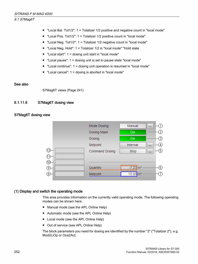
● "Local Bal. Tot1/2": 1 = Totalizer 1/2 positive and negative count in "local mode"
● "Local Pos. Tot1/2": 1 = Totalizer 1/2 positive count in "local mode"
● "Local Neg. Tot1/2": 1 = Totalizer 1/2 negative count in "local mode"
● "Local Neg. Hold": 1 = Totalizer 1/2 in "local mode" "Hold state
● "Local start": 1 = dosing unit start in "local mode"
● "Local pause": 1 = dosing unit is set to pause state "local mode"
● "Local continue": 1 = dosing unit operation is resumed in "local mode"
● "Local cancel": 1 = dosing is aborted in "local mode"
See alsoS7Mag6T views (Page 241)
8.1.11.6 S7Mag6T dosing view
S7Mag6T dosing view
(1) Display and switch the operating modeThis area provides information on the currently valid operating mode. The following operating modes can be shown here:
● Manual mode (see the APL Online Help)
● Automatic mode (see the APL Online Help)
● Local mode (see the APL Online Help)
● Out of service (see APL Online Help)
The block parameters you need for dosing are identified by the number "2" ("Totalizer 2"), e.g. Mod2LiOp or Oos2Act.
SITRANS F M MAG 60008.1 S7Mag6T
SITRANS Library for S7-300252 Function Manual, 02/2018, A5E35351982-02

For more information on operating mode changeover, refer to the "Changeover of the operating state and operating mode" in the APL Online Help.
(2) and (3) Display of the state of the dosing screen form and dosingThis area shows you the the state of the dosing screen form (block input DOnMLi) and of the dosing unit (block input DOnLi).
(4) Displaying and changing the setpoint of the dosing unitThe following states can be shown and changed here:
● "Internal"
● "External"
(5) Displaying and changing the dosing unit: Start, Resume, Pause, and StopThis area shows you the default operating state for the dosing unit. The following states can be shown and changed here:
● "Start"
● "Continue"
● "Pause"
● "Stop"
(6) Display of metered quantityThis area shows you the current dosing quantity.
(7)Displaying and changing the setpointThis area displays the current dosing unit setpoint and lets you edit the setpoint in manual mode.
(8) Display area for block statesThis area provides additional information on the operating state of the block:
● "Invalid signal"
● "Flow"
(9) Display area for dosing unit statesThis area provides additional information on the operating state of the dosing unit:
● "Forced start"
● "Force resume"
SITRANS F M MAG 60008.1 S7Mag6T
SITRANS Library for S7-300Function Manual, 02/2018, A5E35351982-02 253
● "Force pause"
● "Force abort"
● "Request 0/1": A reset to "automatic mode" is expected.
(10), (11) und (12) Display area for dosing unit statesThis area provides additional information on the operating state of the dosing unit:
● "Timeout"
● "Overflow"
● "Negative flow"
See alsoS7Mag6T views (Page 241)
8.1.11.7 Block icon for S7Mag6T
Block icons for S7Mag6T A variety of block icons are available with the following functions:
● Process tag type
● Limits (high/low)
● Alarm and warning limits overshoot/undershoot
● Operating modes
● Internal and external setpoint input (dosing unit only)
● Signal status, release for maintenance
● Force
● Interlocks (dosing unit only)
● Memo display
● Process values (black: volume flow, and orange: Totalizers 1 and 2, or metered quantity)
● Setpoint (blue, dosing unit only)
SITRANS F M MAG 60008.1 S7Mag6T
SITRANS Library for S7-300254 Function Manual, 02/2018, A5E35351982-02
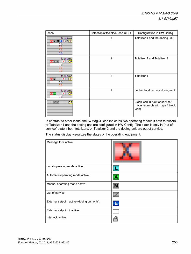
Icons Selection of the block icon in CFC Configuration in HW Config1 Totalizer 1 and the dosing unit
2 Totalizer 1 and Totalizer 2
3 Totalizer 1
4 neither totalizer, nor dosing unit
- Block icon in "Out of service" mode (example with type 1 block icon)
In contrast to other icons, the S7Mag6T icon indicates two operating modes if both totalizers, or Totalizer 1 and the dosing unit are configured in HW Config. The block is only in "out of service" state if both totalizers, or Totalizer 2 and the dosing unit are out of service.
The status display visualizes the states of the operating equipment.
Message lock active:
Local operating mode active:
Automatic operating mode active:
Manual operating mode active:
Out of service:
External setpoint active (dosing unit only):
External setpoint inactive:
Interlock active:
SITRANS F M MAG 60008.1 S7Mag6T
SITRANS Library for S7-300Function Manual, 02/2018, A5E35351982-02 255

Interlock inactive:
Force control active:
Force control inactive:
Switch permission:
The following switching priorities are currently available:
● Operator panel: OP
● Control station OS (local control station): LCS
● Local OS: No icon
For more information on the block icon and operating options in the block icon, refer to the following chapters in the APL Online Help:
● "Configuring the block icons"
● "Block icon structure"
● "Operation via the block icon"
See alsoS7Mag6T views (Page 241)
8.2 S7PMag6T
8.2.1 Description of S7PMag6T
FunctionThe S7PMag6T block is the interface to the operator panel for the technological block S7Mag6T.
SITRANS F M MAG 60008.2 S7PMag6T
SITRANS Library for S7-300256 Function Manual, 02/2018, A5E35351982-02

Configuration notesThe BlockConnector input of the S7PMag6T must be interconnected to any desired S7Mag6T output. So the data that are important for the block (as information about states or messages) are automatically analyzed and displayed by the panel block.
Note
The ENO output must not be used for interconnection with the Blockconnector input.
Calling OBsThe cyclic interrupt OB into which you install the block (e.g. OB32). Additionally in the OB100 (see "Startup characteristics").
Startup characteristicsThe RunUpCyc parameter can be used to specify for how long (number of cycles) the messages are to be suppressed.
Restart = TRUE can be used to simulate a restart.
Called blocksSFC6 RD_SINFOSFC24 TEST_DB
8.2.2 S7PMag6T connections
Input parameters
Parameter Description Type DefaultEN 1 = Called block will be processed BOOL 1Restart Manual startup BOOL 0Op_ModeTot1 Operator Input Totalizer 1 WORD 16#0000Op_Bal1Man Operator Input Totalizer 1: Up
counter for positive flow and down counter for negative flow in manual mode
BOOL 0
Op_Pos1Man Operator Input Totalizer 1: Incre‐ment only for positive flow in manual mode
BOOL 0
Op_Neg1Man Operator Input Totalizer 1: Dec‐rement only for negative flow in manual mode
BOOL 0
Op_Hold1Man Operator Input Totalizer 1: Stop totalizer in manual mode
BOOL 0
SITRANS F M MAG 60008.2 S7PMag6T
SITRANS Library for S7-300Function Manual, 02/2018, A5E35351982-02 257

Parameter Description Type DefaultOp_ModeTot2 Operator Input Totalizer 2 WORD 16#0000Op_Bal2Man Operator Input Totalizer 2: Up
counter for positive flow and down counter for negative flow in manual mode
BOOL 0
Op_Pos2Man Operator Input Totalizer 2: Incre‐ment only for positive flow in manual mode
BOOL 0
Op_Neg2Man Operator Input Totalizer 2: Dec‐rement only for negative flow in manual mode
BOOL 0
Op_Hold2Man Operator Input Totalizer 2: Stop totalizer in manual mode
BOOL 0
Op_DSrtMan Operator Input Dosing: 1 = Se‐lect Start in "manual mode"
BOOL 0
Op_DStpMan Operator Input Dosing: 1 = Se‐lect Cancel in "manual mode"
BOOL 0
Op_DPauseMan Operator Input Dosing: Pause dosing in Manual Mode
BOOL 0
Op_DContMan Operator Input Dosing: 1 = Se‐lect continue in "manual mode"
BOOL 0
Op_VolFlow Operator Input Current volume flow (AI from HW Config)
REAL 0.0
Op_VF_HiLim High Limit Volume flow REAL 100.0Op_VF_LoLim Low Limit Volume flow REAL 0.0Op_Tot1VF Operator Panel: Current value of
Totalizer 1 REAL 0.0
Op_Tot2VF Operator Panel: Current value of Totalizer 2
REAL 0.0
Op_DSP Operator Panel Dosing: Current Setpoint
REAL 0.0
Op_DSP_HiLim High Limit DSP REAL 100.0Op_DSP_LoLim Low Limit DSP REAL 0.0EnAux Enable associated value view BOOL 0Aux1 Associated value 1 (WinCC flexi‐
ble parameter)REAL 0.0
Aux2 Associated value 2 (WinCC flexi‐ble parameter)
REAL 0.0
Aux3 Associated value 3 (WinCC flexi‐ble parameter)
REAL 0.0
Aux4 Associated value 4 (WinCC flexi‐ble parameter)
REAL 0.0
OSStat WinCC status DWORD 16#00000000OSStat2 Status 2 WinCC DWORD 16#00000000OSStatAl Bit reporting procedure (WinCC
flexible parameter)DWORD 16#00000000
Op_MsgFilter Message filter for WinCC flexible DINT 0
SITRANS F M MAG 60008.2 S7PMag6T
SITRANS Library for S7-300258 Function Manual, 02/2018, A5E35351982-02

Parameter Description Type DefaultOp_PermLog Operator permission DWORD 16#00000000Op_Visibility Object visibility DWORD 16#00000000SwitchPerm Switch permission INT 1PanelPerm Panel operating level INT 3BlockConnector Connection to S7Mag6T block ANY RunUpCyc Number of run-up cycles with
message suppressionINT 10
AS_Nr AS number for message filter (max. 999)
INT 1
Output parameters
Parameter Description Type DefaultENO BOOL 0SwitchPerm_Out Switch permission INT 1OSStat_Out WinCC status DWORD 16#00000000OSStat2_Out Status 2 WinCC DWORD 16#00000000OSStatAl_Out Bit reporting procedure (WinCC flexi‐
ble parameter)DWORD 16#00000000
PanelAct Panel active BOOL 0MsgFilter Message filter DINT 0IDBNo Number instance DB INT 0DB_ConnErr DB connection error BOOL 1
Status word allocation for OSStatAl and OSStatAl_Out parameters
Bit0 BOOL External error oc‐curred (CSF)
… Bit5 BOOL External message
1Bit6 BOOL External message
2Bit7 BOOL External message
3Bit8 BOOL Dosing Aborted… Bit16 BOOL VF_AH_ActBit17 BOOL VF_WH_ActBit18 BOOL VF_WL_ActBit19 BOOL VF_AL_ActBit20 BOOL ErrReadConfig
SITRANS F M MAG 60008.2 S7PMag6T
SITRANS Library for S7-300Function Manual, 02/2018, A5E35351982-02 259
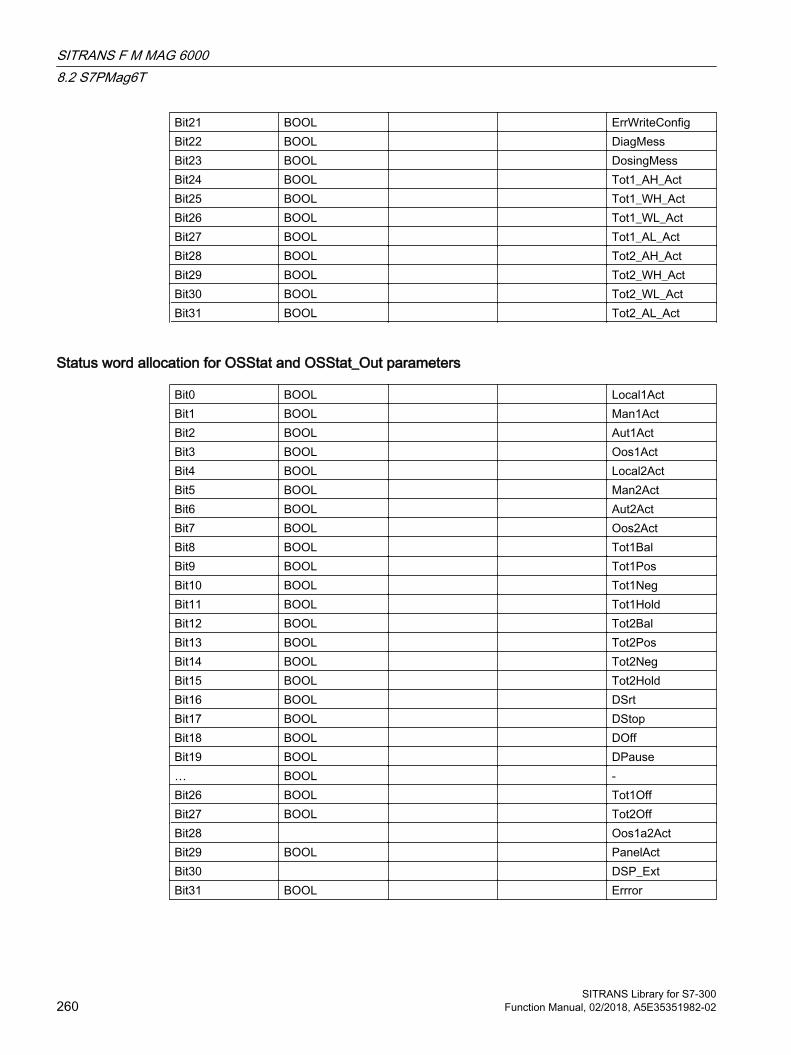
Bit21 BOOL ErrWriteConfigBit22 BOOL DiagMessBit23 BOOL DosingMessBit24 BOOL Tot1_AH_ActBit25 BOOL Tot1_WH_ActBit26 BOOL Tot1_WL_ActBit27 BOOL Tot1_AL_ActBit28 BOOL Tot2_AH_ActBit29 BOOL Tot2_WH_ActBit30 BOOL Tot2_WL_ActBit31 BOOL Tot2_AL_Act
Status word allocation for OSStat and OSStat_Out parameters
Bit0 BOOL Local1ActBit1 BOOL Man1ActBit2 BOOL Aut1ActBit3 BOOL Oos1Act Bit4 BOOL Local2ActBit5 BOOL Man2Act Bit6 BOOL Aut2ActBit7 BOOL Oos2ActBit8 BOOL Tot1BalBit9 BOOL Tot1PosBit10 BOOL Tot1NegBit11 BOOL Tot1Hold Bit12 BOOL Tot2BalBit13 BOOL Tot2PosBit14 BOOL Tot2NegBit15 BOOL Tot2Hold Bit16 BOOL DSrtBit17 BOOL DStopBit18 BOOL DOffBit19 BOOL DPause… BOOL -Bit26 BOOL Tot1OffBit27 BOOL Tot2OffBit28 Oos1a2ActBit29 BOOL PanelActBit30 DSP_ExtBit31 BOOL Errror
SITRANS F M MAG 60008.2 S7PMag6T
SITRANS Library for S7-300260 Function Manual, 02/2018, A5E35351982-02

Status word allocation for OSStat2 and OSStat2_Outs parameters
Bit0 BOOL DosingEndedBit1 BOOL - Bit2 BOOL ForcedStartBit3 BOOL ForcedAbort Bit4 BOOL ForcedPauseBit5 BOOL ForcedCont Bit6 BOOL Request01Bit7 BOOL InvalidSigBit8 BOOL FlowBit9 BOOL -… Bit31 BOOL -
8.2.3 Operator Control and Monitoring WinCC
Operator Control and Monitoring WinCCYou will find more information in Panel blocks, general (Page 13)
8.2.4 Operator Control and Monitoring WinCC flexible
8.2.4.1 Views
Operator Control and Monitoring WinCC flexibleThe block provides the following views:
● Standard view of S7Mag6T (Page 262)
● Message view
● Associated value view
SITRANS F M MAG 60008.2 S7PMag6T
SITRANS Library for S7-300Function Manual, 02/2018, A5E35351982-02 261

8.2.4.2 Standard view of S7Mag6T
Totalizer and dosing unit
Totalizer and totalizer
SITRANS F M MAG 60008.2 S7PMag6T
SITRANS Library for S7-300262 Function Manual, 02/2018, A5E35351982-02
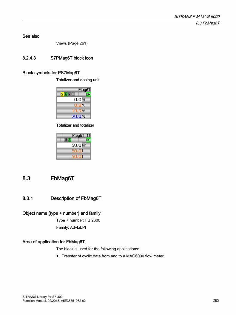
See alsoViews (Page 261)
8.2.4.3 S7PMag6T block icon
Block symbols for PS7Mag6T Totalizer and dosing unit
Totalizer and totalizer
8.3 FbMag6T
8.3.1 Description of FbMag6T
Object name (type + number) and family Type + number: FB 2600
Family: AdvLibPI
Area of application for FbMag6T The block is used for the following applications:
● Transfer of cyclic data from and to a MAG6000 flow meter.
SITRANS F M MAG 60008.3 FbMag6T
SITRANS Library for S7-300Function Manual, 02/2018, A5E35351982-02 263

How it works The block reads/writes all cyclic data of a MAG6000 from/to the process image in cyclic mode.
Note
All cyclic data of the MAG6000 configured in the HW Config. must be addressed within the process image.
Configuration Use the CFC editor to install the block in a cyclic interrupt OB (OB30 to OB38).
When the CFC function "Generate module drivers" is used, the following occurs automatically:
● The member variables of input structure Addr (.Tot1/2, .SetTot1/2, .ModeTot1/2, .DCtr, .DSta, .DSetP, .DComp) are assigned the address parameters configured in HW Config. The member variable is assigned the value -1 if an element is not configured in HW Config.
● The SubnTyp input parameter is set to 1 if the MAG6000 is connected to a CPU via CP (external DP interface), otherwise to 0.
● The Mode in/out parameter is interconnected to the corresponding OMode_xx output parameter of the MOD_XXXX block.
● The DataXchg in/out parameter is interconnected to the corresponding DataXchg_xx output parameter of the MOD_XXXX block.
● The MS parameter is interconnected to the O_MS output parameter of the diagnostics driver block.
Write the volume flow (AI) address that was generated in HW Config to input parameter AVolFlow.
Note
If you are not using the CFC function "Generate module drivers", parameterize the addresses of input structure Addr and the Mode in/out parameter manually. The block expects the values Mode = 16#80xxxxxx for "I/O data can be read", and 16#00xxxxxx (or RackF = TRUE) for "invalid I/O data".
The Addr input structure gets the following values:
Parameter AddressingAVolFlow Volume flow input address (AI)Addr.Tot1 Input address Totalizer 1 (TOTAL, slot 2)Addr.SetTot1 Output address Reset Totalizer 1 (SET_TOT, slot 2)Addr.ModeTot1 Output address command Totalizer 1 (MODE_TOT, slot 2)Addr.Tot2 Input address Totalizer 2/dosing value (TOTAL, slot 3)Addr.SetTot2 Output address Reset Totalizer 2 (SET_TOT, slot 3)Addr.ModeTot2 Output address command Totalizer 2 (MODE_TOT, slot 3)Addr.DCtr Output address control byte (MODE_TOT, slot 3)
SITRANS F M MAG 60008.3 FbMag6T
SITRANS Library for S7-300264 Function Manual, 02/2018, A5E35351982-02

Addr.DSta Input address dosing unit status (B_STA, slot 3)Addr.DSetP Output address dosing setpoint (SETP, slot 3)Addr.DComp Output address dosing unit compensation (SETP, slot 3)
The length of the elements have to be considered when the right address is selected.
Example:
Resultant configurations at block FbMag6T:
Inputs
● AVolFlow = 800
● Addr.Tot1 = 500 (4 Byte Real + 1 Byte Status)
● Addr.Tot2 = 600 (4 Byte Real + 1 Byte Status)
● Addr.DSta = 605 (1 Byte)
Outputs
● Addr.SetTot1 = 400 (1 Byte)
● Addr.ModeTot1 = 401 (1 Byte)
● Addr.SetTot2 = -1 (not configured)
● Addr.ModeTot2 = -1 (not configured)
● Addr.DCtr = 700 (1 Byte)
● Addr.DSetP = 701 (4 Byte Real + 1 Byte Status)
● Addr.DComp = 706 4 Byte Real + 1 Byte Status)
Address -1 is set by default if no value is configured.
A template for process tag types is available in the SITRANS Library as an example for the FbMag6T block:
Example of a process tag type:
● Template of Mag6T
SITRANS F M MAG 60008.3 FbMag6T
SITRANS Library for S7-300Function Manual, 02/2018, A5E35351982-02 265
Startup characteristics ● FbMag6T sets bit 16#xx01xxxx of the Mode input to signal a restart.
● The module ID is read from the addressed DP Slave and verified for consistency with that of MAG6000. Output QModF (module error) is set if the result is negative.
● OB100 transfers the following values to the module if the corresponding modules are configured in HW Config:- Reset the totalizer (SET_TOT): 16#00 (no Reset)- Command of totalizers (MODE_TOT): 16#04 (invalid command to prevent changes of the totalizer states)- Dosing commands (DCtr): 16#00 (no enable, no command)
Status word allocation for Status parameter This block does not have the Status parameter.
8.3.2 Operating modes for FbMag6TThis block does not have any operating modes.
8.3.3 Functions of FbMag6TThe functions for this block are listed below.
Read cyclic values from process imageThe process values are read from the process image (partition) at each block call and then written, including their signal states, to output structure CyclData.Input as well as to the outputs VolFlow, Tot1VF and Tot2VF. The values are addressed via input structure Addr, with -1 indicating that the corresponding value was not configured in HW Config.
Writing cyclic values to the process imageThe source for values that are written cyclically to the process image depends on the setting at input parameter SelStrInputs:
● SelStrInputs = FALSE (default): The values and signal states for the I/O outputs are transferred from output structure CyclData.Output which is interconnected with visualization block Mag6T.
● SelStrInputs = TRUE: The values and signal states for the I/O outputs are transferred from the SetTot1/2, ModeTot1/2, DCtr, DSetP, DComp inputs and their signal states to the device.
SITRANS F M MAG 60008.3 FbMag6T
SITRANS Library for S7-300266 Function Manual, 02/2018, A5E35351982-02

Retain last values if I/O values are invalidThe block retains the last valid values if invalid I/O values were found (inputs <> 16#80xxxxxx or RackF = TRUE).
Signal state for process valuesThe signal state of process values (output structure CyclicData.Inputs) is derived from the higher-level error, or from the signal state returned by MAG6000. In the case of higher-level errors such as rack failure (inputs Mode <> 16#80xxxxxx or RackF = TRUE), status (.ST) 16#00 is output and otherwise the value provided by MAG6000.
Simulating signalsThe block does not have a function for simulating process values.
8.3.4 Error handling of FbMag6T
Error handling of FbMag6T The following errors can be displayed for this block:
● Higher-level error
● Module errors
Higher-level errorHigher-level errors are indicated by the value 1 at output parameter QRackF if the signal state in the HighWord of input parameter Mode changes to a value other than 16#80 , or if input RackF is set.
The CyclData.Csf output is set in addition, and the signal status 16#00 output in the output parameters Input.VolFlow.ST, Input.Tot1VF.ST and Input.Tot2VF.ST as well as at the outputs QCVolFlow, QCTot1VF and QCTot2VF.
Module errorsIf an incorrect module ID of the connected DP slave is read from the block, output QModF will be set. The Quality Codes are set to 16#00 as with the higher-level error.
8.3.5 Messaging of FbMag6T
Messaging This block does not offer messaging.
SITRANS F M MAG 60008.3 FbMag6T
SITRANS Library for S7-300Function Manual, 02/2018, A5E35351982-02 267
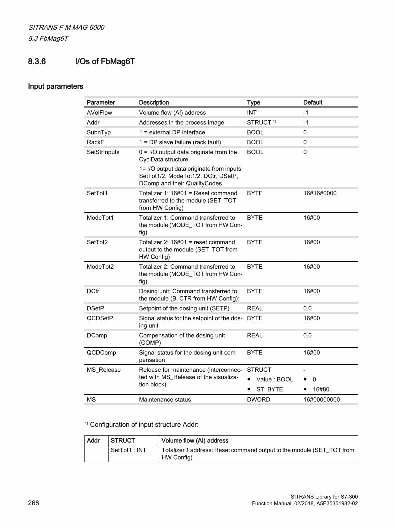
8.3.6 I/Os of FbMag6T
Input parameters
Parameter Description Type DefaultAVolFlow Volume flow (AI) address INT -1Addr Addresses in the process image STRUCT 1) -1SubnTyp 1 = external DP interface BOOL 0RackF 1 = DP slave failure (rack fault) BOOL 0SelStrInputs 0 = I/O output data originate from the
CyclData structure1= I/O output data originate from inputs SetTot1/2, ModeTot1/2, DCtr, DSetP, DComp and their QualityCodes
BOOL 0
SetTot1 Totalizer 1: 16#01 = Reset command transferred to the module (SET_TOT from HW Config)
BYTE 16#16#0000
ModeTot1 Totalizer 1: Command transferred to the module (MODE_TOT from HW Con‐fig)
BYTE 16#00
SetTot2 Totalizer 2: 16#01 = reset command output to the module (SET_TOT from HW Config)
BYTE 16#00
ModeTot2 Totalizer 2: Command transferred to the module (MODE_TOT from HW Con‐fig)
BYTE 16#00
DCtr Dosing unit: Command transferred to the module (B_CTR from HW Config):
BYTE 16#00
DSetP Setpoint of the dosing unit (SETP) REAL 0.0QCDSetP Signal status for the setpoint of the dos‐
ing unitBYTE 16#00
DComp Compensation of the dosing unit (COMP)
REAL 0.0
QCDComp Signal status for the dosing unit com‐pensation
BYTE 16#00
MS_Release Release for maintenance (interconnec‐ted with MS_Release of the visualiza‐tion block)
STRUCT● Value : BOOL● ST: BYTE
-● 0● 16#80
MS Maintenance status DWORD 16#00000000
1) Configuration of input structure Addr:
Addr STRUCT Volume flow (AI) address SetTot1 : INT Totalizer 1 address: Reset command output to the module (SET_TOT from
HW Config)
SITRANS F M MAG 60008.3 FbMag6T
SITRANS Library for S7-300268 Function Manual, 02/2018, A5E35351982-02
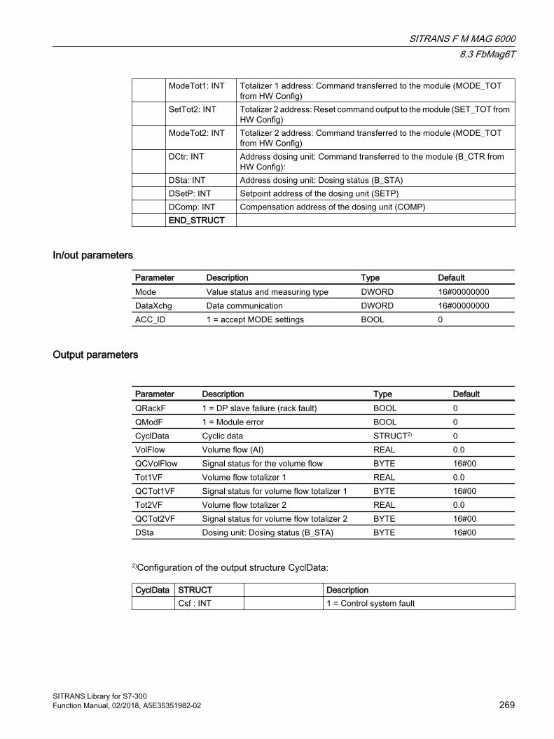
ModeTot1: INT Totalizer 1 address: Command transferred to the module (MODE_TOT from HW Config)
SetTot2: INT Totalizer 2 address: Reset command output to the module (SET_TOT from HW Config)
ModeTot2: INT Totalizer 2 address: Command transferred to the module (MODE_TOT from HW Config)
DCtr: INT Address dosing unit: Command transferred to the module (B_CTR from HW Config):
DSta: INT Address dosing unit: Dosing status (B_STA) DSetP: INT Setpoint address of the dosing unit (SETP) DComp: INT Compensation address of the dosing unit (COMP) END_STRUCT
In/out parameters
Parameter Description Type DefaultMode Value status and measuring type DWORD 16#00000000DataXchg Data communication DWORD 16#00000000ACC_ID 1 = accept MODE settings BOOL 0
Output parameters
Parameter Description Type DefaultQRackF 1 = DP slave failure (rack fault) BOOL 0QModF 1 = Module error BOOL 0CyclData Cyclic data STRUCT2) 0VolFlow Volume flow (AI) REAL 0.0QCVolFlow Signal status for the volume flow BYTE 16#00Tot1VF Volume flow totalizer 1 REAL 0.0QCTot1VF Signal status for volume flow totalizer 1 BYTE 16#00Tot2VF Volume flow totalizer 2 REAL 0.0QCTot2VF Signal status for volume flow totalizer 2 BYTE 16#00DSta Dosing unit: Dosing status (B_STA) BYTE 16#00
2)Configuration of the output structure CyclData:
CyclData STRUCT Description Csf : INT 1 = Control system fault
SITRANS F M MAG 60008.3 FbMag6T
SITRANS Library for S7-300Function Manual, 02/2018, A5E35351982-02 269
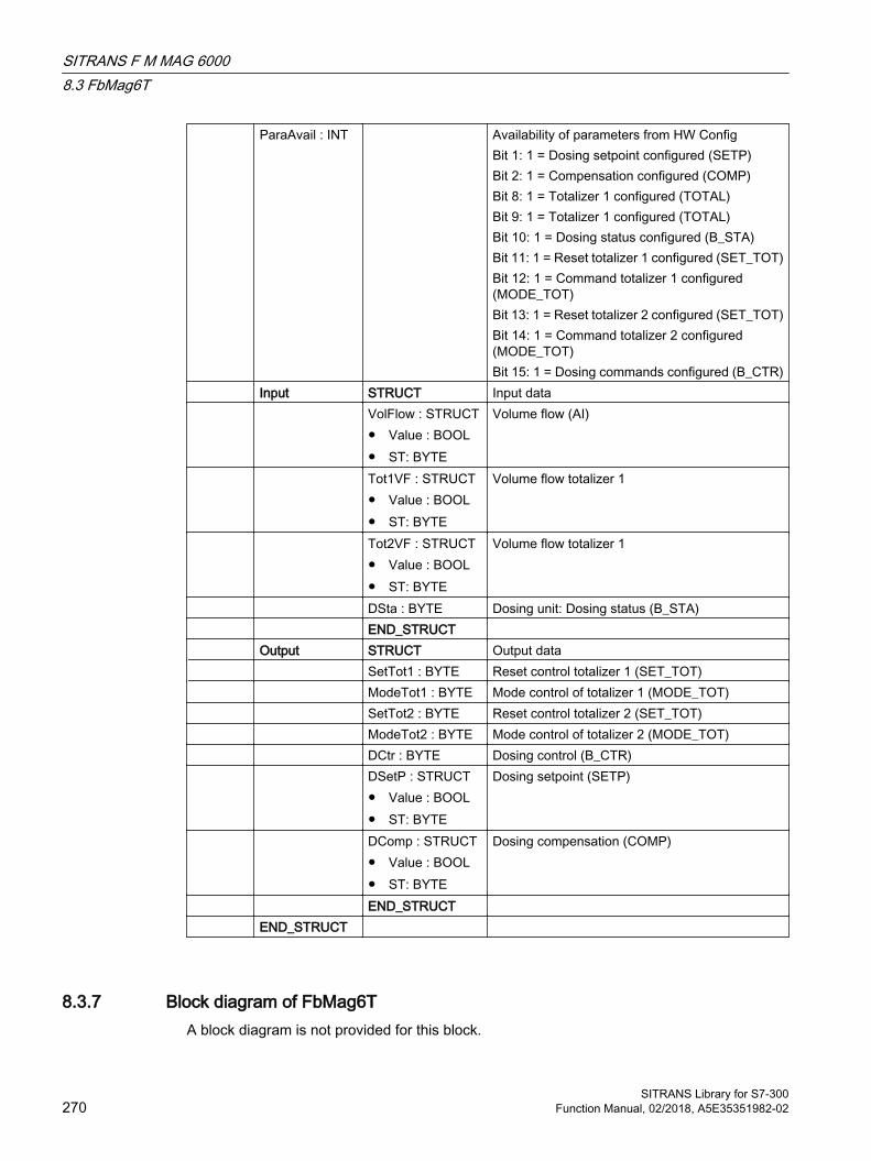
ParaAvail : INT Availability of parameters from HW ConfigBit 1: 1 = Dosing setpoint configured (SETP)Bit 2: 1 = Compensation configured (COMP)Bit 8: 1 = Totalizer 1 configured (TOTAL)Bit 9: 1 = Totalizer 1 configured (TOTAL)Bit 10: 1 = Dosing status configured (B_STA)Bit 11: 1 = Reset totalizer 1 configured (SET_TOT)Bit 12: 1 = Command totalizer 1 configured (MODE_TOT)Bit 13: 1 = Reset totalizer 2 configured (SET_TOT)Bit 14: 1 = Command totalizer 2 configured (MODE_TOT)Bit 15: 1 = Dosing commands configured (B_CTR)
Input STRUCT Input data VolFlow : STRUCT
● Value : BOOL● ST: BYTE
Volume flow (AI)
Tot1VF : STRUCT● Value : BOOL● ST: BYTE
Volume flow totalizer 1
Tot2VF : STRUCT● Value : BOOL● ST: BYTE
Volume flow totalizer 1
DSta : BYTE Dosing unit: Dosing status (B_STA) END_STRUCT Output STRUCT Output data SetTot1 : BYTE Reset control totalizer 1 (SET_TOT) ModeTot1 : BYTE Mode control of totalizer 1 (MODE_TOT) SetTot2 : BYTE Reset control totalizer 2 (SET_TOT) ModeTot2 : BYTE Mode control of totalizer 2 (MODE_TOT) DCtr : BYTE Dosing control (B_CTR) DSetP : STRUCT
● Value : BOOL● ST: BYTE
Dosing setpoint (SETP)
DComp : STRUCT● Value : BOOL● ST: BYTE
Dosing compensation (COMP)
END_STRUCT END_STRUCT
8.3.7 Block diagram of FbMag6TA block diagram is not provided for this block.
SITRANS F M MAG 60008.3 FbMag6T
SITRANS Library for S7-300270 Function Manual, 02/2018, A5E35351982-02
SIPART PS2 99.1 S7SipPS2
9.1.1 Description of S7SipPS2
Object name (type + number) and family Type + number: FB 2633
Family: Sipart
Application area of S7SipPS2 The block is used for the following applications:
● Control of a Sipart PS2 with 0/4 to 20 mA with and without HART or Profibus PA I/O
● Control of an optional auxiliary valve for regulating the auxiliary power of the control valve
How it works The Sipart PS2 is brought to a specified position using an analog activation signal.
The block forms the manipulated variable error from the difference between the activation signal and the acquired position feedback and can monitor it for adherence to high and low limits.
The control valve is monitored for the "Open"/"Closed" position. The block can be connected with a digital limit switch for this purpose. The block can generate the digital position signals itself through the adjustable limits for the "Open"/"Closed" position.
Missing feedback can be derived from the control in the block.
Various inputs are available for control purposes. The next chapters provide more detailed information on configuration, operating principles, visualization and operation.
Configuration Use the CFC editor to install the block in a cyclic interrupt OB (OB30 to OB38). The block is also installed automatically in the startup OB (OB100).
The SITRANS Library contains templates for process tag types as examples with various application scenarios for the S7SipPS2 block.
SITRANS Library for S7-300Function Manual, 02/2018, A5E35351982-02 271

Examples of process tag types:
● I/O via 0/4 to 20 mA signal (Sipart PS2 0,4-20mA)
● I/O via 4 to 20 mA signal with HART (Sipart PS2 HART)
● I/O via Profibus PA (Sipart PS2 Profibus PA)
The templates are described in more detail in Template of S7SipPS2 (Page 304).
When the SIPART PS2 is connected to the controller via Profibus PA, Feature2.Bit2 must be set in order to read the configuration data. Optionally, Feature2.Bit0 = TRUE can then be used to evaluate the violation of the control deviation by the device and not by the block.
Feature2.Bit1 specifies whether the optional alarm module is available; Feature2.Bit3 specifies whether the TIM and LIM limits should be read and displayed.
If the Sipart PS2 is connected to the controller via neither HART nor Profibus PA, no configuration data can be read. The bits OS_Perm.Bit29 and OS_Perm.Bit30 are set to FALSE so that no configuration data can be read. Optionally, the values set on the device can be configured manually at the corresponding block inputs for visualization.
Note
If the Sipart PS2 is connected to the controller by means of HART communication and has a firmware version smaller than 5.00.00 , the Feature2.Bit4 must be set to True to enable the block to work correctly.
Startup characteristics Use the Feature Bit Setting the startup characteristics (Page 24) to define the startup characteristics of this block.
The messages are suppressed after startup for the number of cycles set at RunUpCyc.
If the Feature bit "Set startup characteristics" = 0, the following applies to the startup characteristics:
● With Feature bit 16 = 0, the main valve (Sipart PS2) is closed
● With Feature bit 16 = 1, the main valve (Sipart PS2) travels to the neutral position
Status word allocation for Status1 parameter You can find a description for each parameter in section S7SipPS2 connections (Page 292).
Status bit Parameter0 Occupied1 BatchEn2 Not used3 OosAct4 OosLi5 AutoAct6 LocalAct
SIPART PS29.1 S7SipPS2
SITRANS Library for S7-300272 Function Manual, 02/2018, A5E35351982-02
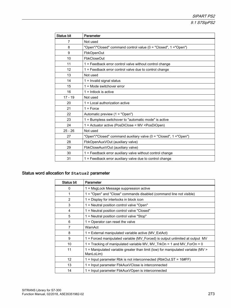
Status bit Parameter7 Not used8 "Open"/"Closed" command control value (0 = "Closed", 1 ="Open")9 FbkOpenOut10 FbkCloseOut11 1 = Feedback error control valve without control change12 1 = Feedback error control valve due to control change13 Not used14 1 = Invalid signal status15 1 = Mode switchover error16 1 = Intlock is active
17 - 19 Not used20 1 = Local authorization active21 1 = Force22 Automatic preview (1 = "Open")23 1 = Bumpless switchover to "automatic mode" is active24 1 = Actuator active (PosDiClose < MV <PosDiOpen)
25 - 26 Not used27 "Open"/"Closed" command auxiliary valve (0 = "Closed", 1 ="Open")28 FbkOpenAuxVOut (auxiliary valve)29 FbkCloseAuxVOut (auxiliary valve)30 1 = Feedback error auxiliary valve without control change31 1 = Feedback error auxiliary valve due to control change
Status word allocation for Status2 parameter
Status bit Parameter0 1 = MsgLock Message suppression active1 1 = "Open" and "Close" commands disabled (command line not visible)2 1 = Display for interlocks in block icon3 1 = Neutral position control valve "Open"4 1 = Neutral position control valve "Closed"5 1 = Neutral position control valve "Stop"6 1 = Operator can reset the valve7 WarnAct8 1 = External manipulated variable active (MV_ExtAct)9 1 = Forced manipulated variable (MV_Forced) is output unlimited at output MV
10 1 = Tracking of manipulated variable MV, MV_TrkOn = 1 and MV_ForOn = 011 1 = Manipulated variable greater than limit (low) for manipulated variable (MV >
ManLoLim)12 1 = Input parameter Rbk is not interconnected (RbkOut.ST = 16#FF)13 1 = Input parameter FbkAuxVClose is interconnected14 1 = Input parameter FbkAuxVOpen is interconnected
SIPART PS29.1 S7SipPS2
SITRANS Library for S7-300Function Manual, 02/2018, A5E35351982-02 273
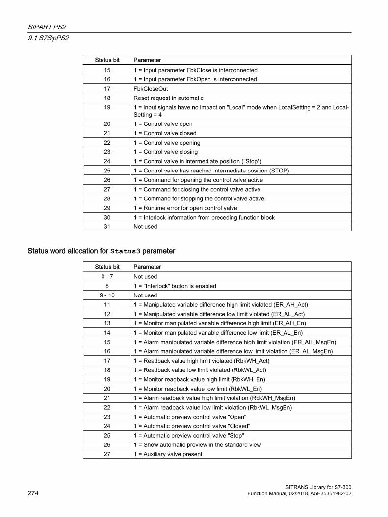
Status bit Parameter15 1 = Input parameter FbkClose is interconnected16 1 = Input parameter FbkOpen is interconnected17 FbkCloseOut18 Reset request in automatic19 1 = Input signals have no impact on "Local" mode when LocalSetting = 2 and Local‐
Setting = 420 1 = Control valve open21 1 = Control valve closed22 1 = Control valve opening23 1 = Control valve closing24 1 = Control valve in intermediate position ("Stop")25 1 = Control valve has reached intermediate position (STOP)26 1 = Command for opening the control valve active27 1 = Command for closing the control valve active28 1 = Command for stopping the control valve active29 1 = Runtime error for open control valve30 1 = Interlock information from preceding function block31 Not used
Status word allocation for Status3 parameter
Status bit Parameter0 - 7 Not used
8 1 = "Interlock" button is enabled9 - 10 Not used
11 1 = Manipulated variable difference high limit violated (ER_AH_Act)12 1 = Manipulated variable difference low limit violated (ER_AL_Act)13 1 = Monitor manipulated variable difference high limit (ER_AH_En)14 1 = Monitor manipulated variable difference low limit (ER_AL_En)15 1 = Alarm manipulated variable difference high limit violation (ER_AH_MsgEn)16 1 = Alarm manipulated variable difference low limit violation (ER_AL_MsgEn)17 1 = Readback value high limit violated (RbkWH_Act)18 1 = Readback value low limit violated (RbkWL_Act)19 1 = Monitor readback value high limit (RbkWH_En)20 1 = Monitor readback value low limit (RbkWL_En)21 1 = Alarm readback value high limit violation (RbkWH_MsgEn)22 1 = Alarm readback value low limit violation (RbkWL_MsgEn)23 1 = Automatic preview control valve "Open"24 1 = Automatic preview control valve "Closed"25 1 = Automatic preview control valve "Stop"26 1 = Show automatic preview in the standard view27 1 = Auxiliary valve present
SIPART PS29.1 S7SipPS2
SITRANS Library for S7-300274 Function Manual, 02/2018, A5E35351982-02

Status bit Parameter28 GrpErr29 RdyToStart
30 - 31 Not used
Status word allocation for Status4 parameter
Status bit Parameter0 1 = External error1 1 = error when reading acyclic data (active only for the duration of one cycle)2 1 = error when writing acyclic data (active only for the duration of one cycle)3 Cbk0 = 1 (Sipart in fail-safe state)4 Cbk1 = 1 (request for local mode of Sipart)5 Cbk2 = 1 (Sipart operated in local mode)6 Cbk11 = 1 (enable for simulation of process values on Sipart)7 Cbk16 = 1 (stroke integral exceeded)8 Bin1 = 1: Message9 Bin1 = 1: Configuration change blocked10 Bin1 = 1: Configuration change blocked/manual11 Bin1 = 1: Travel to end value12 Bin1 = 1: Travel to start value13 Bin1 = 1: Movement blocked14 Bin2 = 1: Message15 Bin2 = 1: Travel to end value16 Bin2 = 1: Travel to start value17 Bin2 = 1: Movement blocked18 1 = Limit violation of alarm, SIA or MLS module19 1 = A1: High alarm limit20 1 = A1: High warning limit21 1 = A1: Low warning limit22 1 = A1: Low alarm limit23 1 = A2: High alarm limit24 1 = A2: High warning limit25 1 = A2: Low warning limit26 1 = A2: Low alarm limit27 1 = Trigger threshold control deviation (Lim) exists28 1 = Monitoring time control deviation (Tim) exists29 OpenForce control valve30 CloseForce control valve31 Not used
SIPART PS29.1 S7SipPS2
SITRANS Library for S7-300Function Manual, 02/2018, A5E35351982-02 275
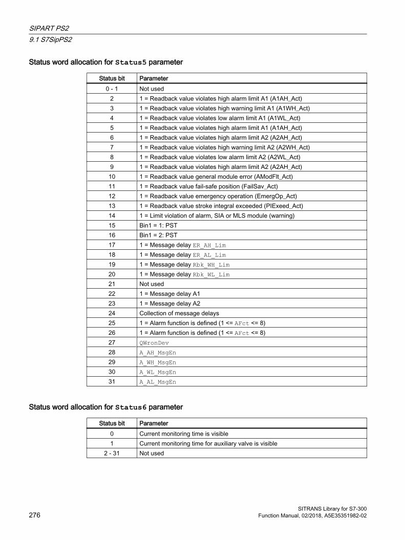
Status word allocation for Status5 parameter
Status bit Parameter0 - 1 Not used
2 1 = Readback value violates high alarm limit A1 (A1AH_Act)3 1 = Readback value violates high warning limit A1 (A1WH_Act)4 1 = Readback value violates low alarm limit A1 (A1WL_Act)5 1 = Readback value violates high alarm limit A1 (A1AH_Act)6 1 = Readback value violates high alarm limit A2 (A2AH_Act)7 1 = Readback value violates high warning limit A2 (A2WH_Act)8 1 = Readback value violates low alarm limit A2 (A2WL_Act)9 1 = Readback value violates high alarm limit A2 (A2AH_Act)10 1 = Readback value general module error (AModFlt_Act)11 1 = Readback value fail-safe position (FailSav_Act)12 1 = Readback value emergency operation (EmergOp_Act)13 1 = Readback value stroke integral exceeded (PIExeed_Act)14 1 = Limit violation of alarm, SIA or MLS module (warning)15 Bin1 = 1: PST16 Bin1 = 2: PST17 1 = Message delay ER_AH_Lim18 1 = Message delay ER_AL_Lim19 1 = Message delay Rbk_WH_Lim20 1 = Message delay Rbk_WL_Lim21 Not used22 1 = Message delay A123 1 = Message delay A224 Collection of message delays25 1 = Alarm function is defined (1 <= AFct <= 8)26 1 = Alarm function is defined (1 <= AFct <= 8)27 QWronDev28 A_AH_MsgEn29 A_WH_MsgEn30 A_WL_MsgEn31 A_AL_MsgEn
Status word allocation for Status6 parameter
Status bit Parameter0 Current monitoring time is visible1 Current monitoring time for auxiliary valve is visible
2 - 31 Not used
SIPART PS29.1 S7SipPS2
SITRANS Library for S7-300276 Function Manual, 02/2018, A5E35351982-02
9.1.2 Operating modes of S7SipPS2The block can be operated using the following modes:
● Local mode
● Automatic mode
● Manual mode
● Out of service
The operating modes are described in more detail in the APL Online Help.
The next section provides additional block-specific information relating to the general descriptions.
"Local mode"The block supports the local operating modes 2 and 4. The control settings for the block are therefore always made based on internal tracking of the feedback value.
You can find general information on "local mode", switching modes and bumpless switchover in the Local mode section.
"Automatic mode"You can find general information on "automatic mode", switching modes and bumpless switchover in the section Manual and automatic mode for motors, valves and dosing units.
With auxiliary valve
In "automatic mode", the automatic commands affect the auxiliary valve, which you can
● "Open" (OpenAut = 1)
● "Close" (CloseAut = 1)
Without auxiliary valve
In "automatic mode", the automatic commands affect the control valve, which you can
● "Open" (OpenAut = 1)
● "Close" (CloseAut = 1)
Note
If no auxiliary valve is configured, no internal manipulated variable specifications can be made in "automatic mode". Manipulated variable specification is set to external when the mode is switched to "automatic".
"Manual mode"You can find general information on "manual mode", switching modes and bumpless switchover in the section Manual and automatic mode for motors, valves and dosing units.
With auxiliary valve:
SIPART PS29.1 S7SipPS2
SITRANS Library for S7-300Function Manual, 02/2018, A5E35351982-02 277

In "manual mode", the operator actions affect the auxiliary valve, which you can:
● "Open" (OpenMan = 1)
● "Close" (CloseMan = 1)
Without auxiliary valve:
In "manual mode", the operator actions affect the control valve, which you can:
● "Open" (OpenMan = 1)
● "Close" (CloseMan = 1)
Note
If no auxiliary valve is configured, no external manipulated variable specifications can be made in the manual operating mode. Manipulated variable specification is set to internal when the mode is switched to manual.
"Out of service"You can find general information about the "out of service" mode in the Out of service section.
9.1.3 Functions of S7SipPS2 The functions for this block are listed below.
Reading and writing configuration data This block uses the inputs RdCfgOp and WrCfgOp to read and write the configuration data from and to the Sipart. The inputs are set using the buttons "Read Config." or "Write Config." in the "Parameter" faceplate view.
Read parameters
● Bin1/Bin2 (function of BE1/BE2)
● MV_OpScale.Low/.High (manipulated variable limit start/end)
● AlarmFct (alarm function)
● AlarmLim1/2 (trigger threshold Alarm 1/2)
● Tim/QTim (monitoring time fault message 'Control deviation')
● Lim/QLim (response threshold fault message 'Control deviation')
Written parameters
● Tim (monitoring time fault message 'Control deviation')
● Lim (response threshold fault message 'Control deviation')
SIPART PS29.1 S7SipPS2
SITRANS Library for S7-300278 Function Manual, 02/2018, A5E35351982-02
Interlocks This block provides the following interlocks:
● Interlock without reset ("Interlock")
Refer to the "Interlocks" and "Influence of the signal status on the interlock" sections in the APL Online Help.
Resetting the block in case of interlocks or errors This block provides the standard "Resetting the block in case of interlocks or errors" function that is described in the APL Online Help.
Group error This block provides the standard "Output group error" function that is described in the APL Online Help.
The following parameters are taken into consideration when forming the group error:
● CSF ● MonDynErr ● MonStaErr ● MonDynAuxVErr ● MonStaAuxVErr
Outputting a signal for start readiness This block provides the standard "Suppress messages" function using the MsgLock parameter that is described in the APL Online Help.
SIMATIC BATCH functionality This block provides the standard "SIMATIC BATCH functionality" function that is described in the APL Online Help.
Tracking and limiting a manipulated variable You can correct the manipulated variable output to the tracking value MV_Trk or the manipulated variable feedback Rbk to realize bumpless switchover. To track the manipulated variable output, you have to set the parameter MV_TrkOn = 1.
If the parameter MV_TrkRbk = 0, the manipulated variable output is corrected to the tracking value MV_Trk. The manipulated variable output MV is limited to the MV_HiLim and MV_LoLim parameters.
If the parameter MV_TrkRbk = 1, the manipulated variable output is tracked to the position feedback Rbk. There are no limits here.
The "Tracking" text is displayed additionally in the standard view of the faceplate.
SIPART PS29.1 S7SipPS2
SITRANS Library for S7-300Function Manual, 02/2018, A5E35351982-02 279

Tracking has a higher priority than interlock for a control valve.
Forming the group status for interlocks This block provides the standard "Form group status for interlock information" function that is described in the APL Online Help.
Forcing operating modesThis block provides the standard "Forcing operating modes" function that is described in the APL Online Help.
Note
If the block is operated with a auxiliary valve, the OpenForce and CloseForce commands also affect the auxiliary valve.
The high range limit (MV_HiLim) and the low range limit (MV_LoLim) are output at MV for OpenForce and CloseForce respectively.
With CloseForce, the auxiliary valve is closed, thereby triggering the neutral position of the control valve regardless of the MV output.
A configured ramp limit has no effect.
Feedback monitoring This block provides the standard "Feedback monitoring" function that is described in the APL Online Help.
Digital feedback signals for the "Open" and "Closed" positions are formed from the position feedback:
● Feedback for "Open" position: Rbk ≥ PosDiOpen● Feedback for "Closed" position: Rbk ≤ PosDiClose
Specifying control valve positionsThere are the positions:
● Valve closed ("Closed")
● Valve closes
● Valve open ("Open")
● Valve opens
● Valve has reached defined position
Valve closed ("Closed")
SIPART PS29.1 S7SipPS2
SITRANS Library for S7-300280 Function Manual, 02/2018, A5E35351982-02
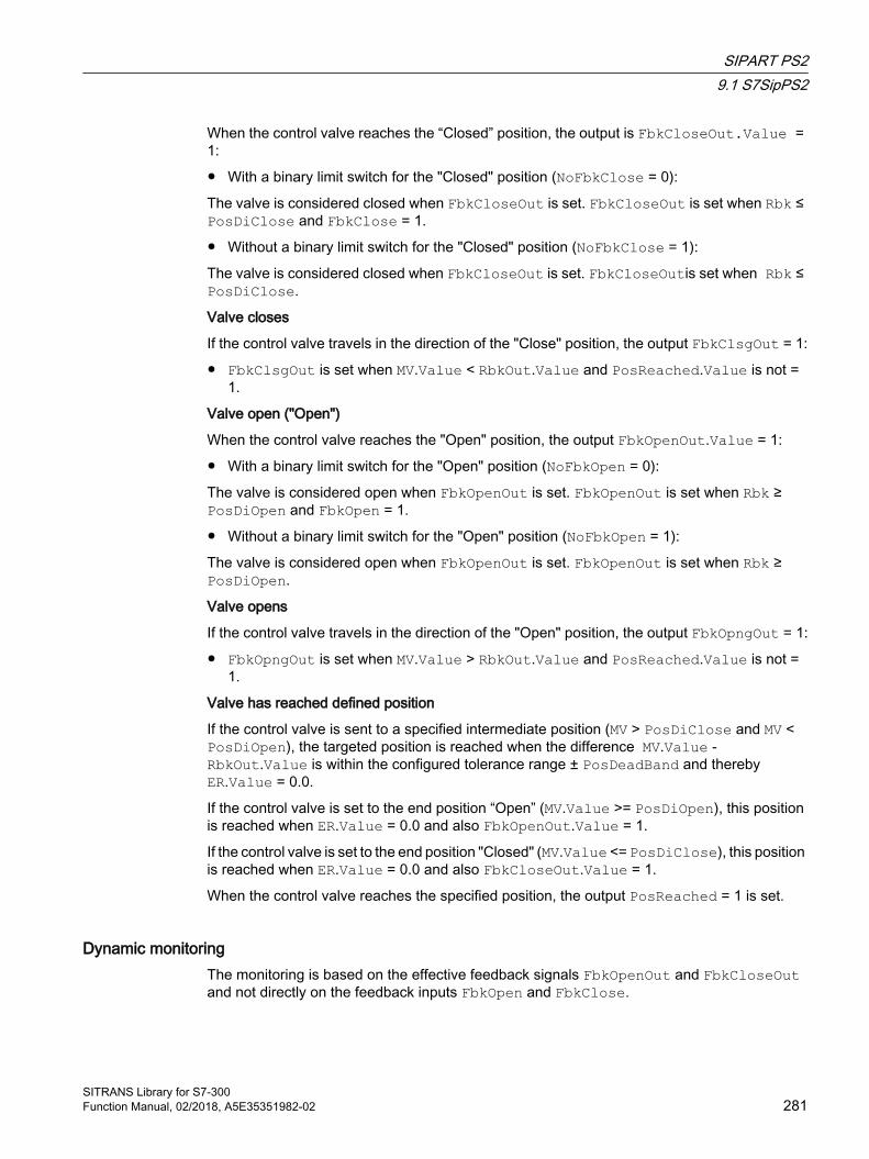
When the control valve reaches the “Closed” position, the output is FbkCloseOut.Value = 1:
● With a binary limit switch for the "Closed" position (NoFbkClose = 0):
The valve is considered closed when FbkCloseOut is set. FbkCloseOut is set when Rbk ≤ PosDiClose and FbkClose = 1.
● Without a binary limit switch for the "Closed" position (NoFbkClose = 1):
The valve is considered closed when FbkCloseOut is set. FbkCloseOutis set when Rbk ≤ PosDiClose.
Valve closes
If the control valve travels in the direction of the "Close" position, the output FbkClsgOut = 1:
● FbkClsgOut is set when MV.Value < RbkOut.Value and PosReached.Value is not = 1.
Valve open ("Open")
When the control valve reaches the "Open" position, the output FbkOpenOut.Value = 1:
● With a binary limit switch for the "Open" position (NoFbkOpen = 0):
The valve is considered open when FbkOpenOut is set. FbkOpenOut is set when Rbk ≥ PosDiOpen and FbkOpen = 1.
● Without a binary limit switch for the "Open" position (NoFbkOpen = 1):
The valve is considered open when FbkOpenOut is set. FbkOpenOut is set when Rbk ≥ PosDiOpen.
Valve opens
If the control valve travels in the direction of the "Open" position, the output FbkOpngOut = 1:
● FbkOpngOut is set when MV.Value > RbkOut.Value and PosReached.Value is not = 1.
Valve has reached defined position
If the control valve is sent to a specified intermediate position (MV > PosDiClose and MV < PosDiOpen), the targeted position is reached when the difference MV.Value - RbkOut.Value is within the configured tolerance range ± PosDeadBand and thereby ER.Value = 0.0.
If the control valve is set to the end position “Open” (MV.Value >= PosDiOpen), this position is reached when ER.Value = 0.0 and also FbkOpenOut.Value = 1.
If the control valve is set to the end position "Closed" (MV.Value <= PosDiClose), this position is reached when ER.Value = 0.0 and also FbkCloseOut.Value = 1.
When the control valve reaches the specified position, the output PosReached = 1 is set.
Dynamic monitoringThe monitoring is based on the effective feedback signals FbkOpenOut and FbkCloseOut and not directly on the feedback inputs FbkOpen and FbkClose.
SIPART PS29.1 S7SipPS2
SITRANS Library for S7-300Function Manual, 02/2018, A5E35351982-02 281

The monitoring is only active if the control valve is within the control range. The operating range is determined by the limits PosDiClose and PosDiOpen (PosDiClose < Rbk < PosDiOpen).
When the control valve is within the control range, to reach one of the two end positions (MV ≥ PosDiOpen or MV ≤ PosDiClose), the targeted end position must be reached within the time defined by MonTiDynamic.
If there are binary signals for the feedback of the control valve, the monitoring time for reaching the configured values for the "Open" (PosDiOpen) or "Closed" (PosDiClose) position of the manipulated variable is started (start MonTiDynamic if MV ≤ PosDiClose or MV ≥ PosDiOpen).
A dynamic monitoring error is generated if:
● The "Closed" end position is targeted (MV ≤ PosDiClose) and this position (FbkCloseOut) is not reached within the monitoring time MonTiDynamic.
● The "Closed" end position is targeted (MV ≤ PosDiClose) and the feedback of the binary limit switch FbkClose is already within the operating range.
● The "Open" end position is targeted (MV ≥ PosDiOpen) and this position (FbkOpenOut) is not reached within the monitoring time MonTiDynamic.
● The "Open" end position is targeted (MV ≥ PosDiOpen) and the feedback of the binary limit switch FbkOpen is already within the operating range.
Static monitoringThe monitoring is based on the effective feedback signals FbkOpenOut and FbkCloseOut and not on the feedback inputs FbkOpen and FbkClose.
Monitoring is only active if the control valve is in the "Closed" or "Open" position and not in the neutral position. The "Closed" position is determined by the PosDiClose parameter and the "Open" position by the PosDiOpen parameter.
A static monitoring error is generated if:
● The "Closed" end position (FbkCloseOut = 1) is exited without a command having been issued first and the monitoring time MonTiStatic has expired.
● The "Closed" end position is reached (FbkCloseOut = 1), the feedback for the binary limit switch FbkClose is gone, and monitoring time MonTiStatic has expired.
● The "Open" end position (FbkOpenOut = 1) is exited without a command having been issued first and the monitoring time MonTiStatic has expired.
● The "Open" end position is reached (FbkOpenOut = 1), the feedback for the binary limit switch FbkOpen is gone, and monitoring time MonTiStatic has expired.
Deactivate feedback This block provides the standard "Disabling feedback for valves" function that is described in the APL Online Help. Feedback monitoring can be deactivated separately for each feedback with NoFbkOpen or NoFbkClose as required.
SIPART PS29.1 S7SipPS2
SITRANS Library for S7-300282 Function Manual, 02/2018, A5E35351982-02
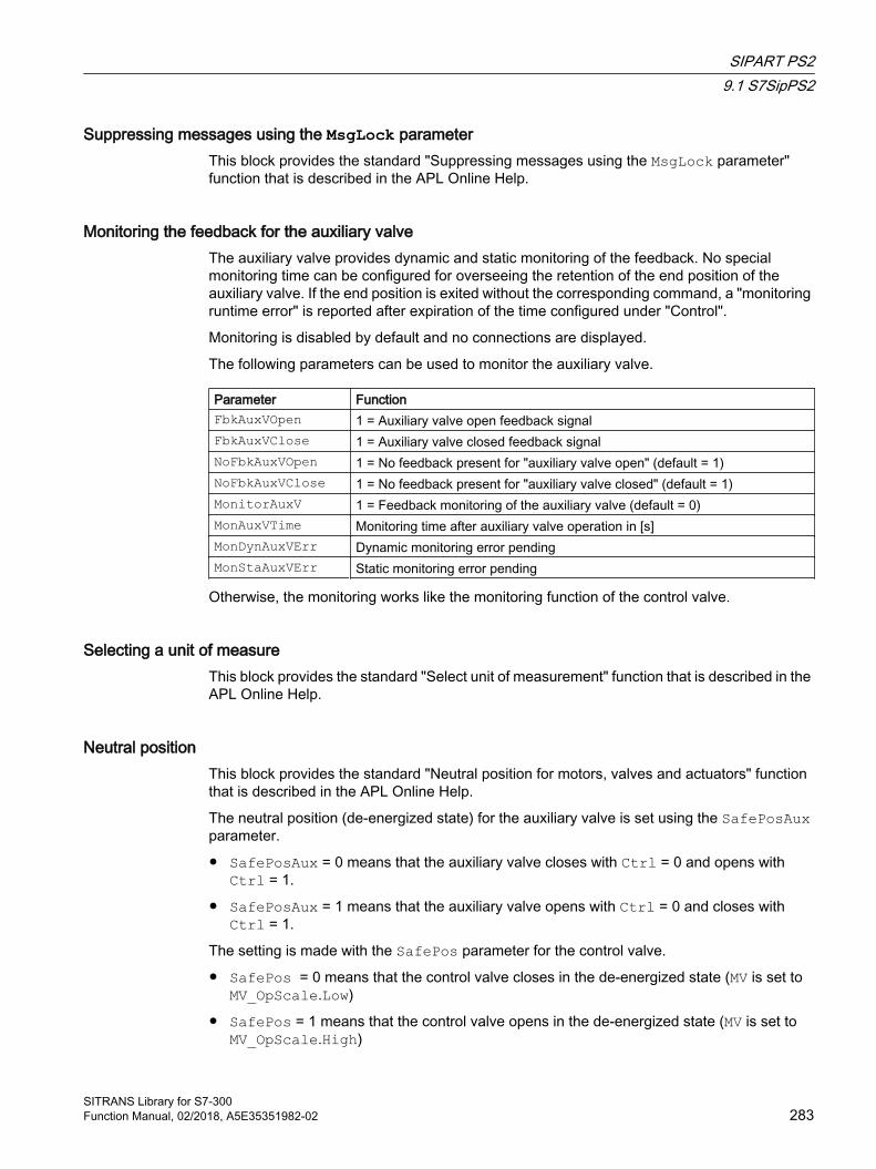
Suppressing messages using the MsgLock parameter This block provides the standard "Suppressing messages using the MsgLock parameter" function that is described in the APL Online Help.
Monitoring the feedback for the auxiliary valveThe auxiliary valve provides dynamic and static monitoring of the feedback. No special monitoring time can be configured for overseeing the retention of the end position of the auxiliary valve. If the end position is exited without the corresponding command, a "monitoring runtime error" is reported after expiration of the time configured under "Control".
Monitoring is disabled by default and no connections are displayed.
The following parameters can be used to monitor the auxiliary valve.
Parameter FunctionFbkAuxVOpen 1 = Auxiliary valve open feedback signalFbkAuxVClose 1 = Auxiliary valve closed feedback signalNoFbkAuxVOpen 1 = No feedback present for "auxiliary valve open" (default = 1)NoFbkAuxVClose 1 = No feedback present for "auxiliary valve closed" (default = 1)MonitorAuxV 1 = Feedback monitoring of the auxiliary valve (default = 0)MonAuxVTime Monitoring time after auxiliary valve operation in [s]MonDynAuxVErr Dynamic monitoring error pendingMonStaAuxVErr Static monitoring error pending
Otherwise, the monitoring works like the monitoring function of the control valve.
Selecting a unit of measure This block provides the standard "Select unit of measurement" function that is described in the APL Online Help.
Neutral position This block provides the standard "Neutral position for motors, valves and actuators" function that is described in the APL Online Help.
The neutral position (de-energized state) for the auxiliary valve is set using the SafePosAux parameter.
● SafePosAux = 0 means that the auxiliary valve closes with Ctrl = 0 and opens with Ctrl = 1.
● SafePosAux = 1 means that the auxiliary valve opens with Ctrl = 0 and closes with Ctrl = 1.
The setting is made with the SafePos parameter for the control valve.
● SafePos = 0 means that the control valve closes in the de-energized state (MV is set to MV_OpScale.Low)
● SafePos = 1 means that the control valve opens in the de-energized state (MV is set to MV_OpScale.High)
SIPART PS29.1 S7SipPS2
SITRANS Library for S7-300Function Manual, 02/2018, A5E35351982-02 283
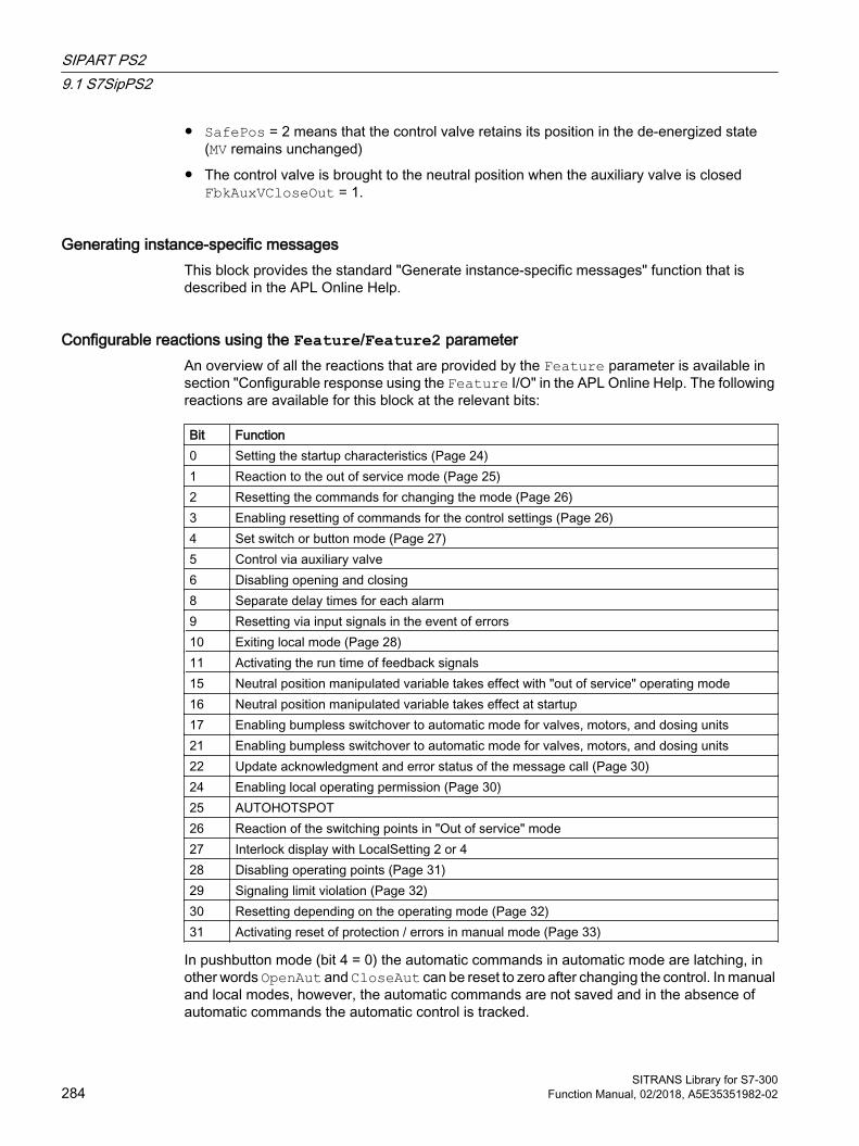
● SafePos = 2 means that the control valve retains its position in the de-energized state (MV remains unchanged)
● The control valve is brought to the neutral position when the auxiliary valve is closed FbkAuxVCloseOut = 1.
Generating instance-specific messages This block provides the standard "Generate instance-specific messages" function that is described in the APL Online Help.
Configurable reactions using the Feature/Feature2 parameter An overview of all the reactions that are provided by the Feature parameter is available in section "Configurable response using the Feature I/O" in the APL Online Help. The following reactions are available for this block at the relevant bits:
Bit Function0 Setting the startup characteristics (Page 24)1 Reaction to the out of service mode (Page 25)2 Resetting the commands for changing the mode (Page 26)3 Enabling resetting of commands for the control settings (Page 26)4 Set switch or button mode (Page 27)5 Control via auxiliary valve6 Disabling opening and closing8 Separate delay times for each alarm9 Resetting via input signals in the event of errors10 Exiting local mode (Page 28)11 Activating the run time of feedback signals15 Neutral position manipulated variable takes effect with "out of service" operating mode16 Neutral position manipulated variable takes effect at startup17 Enabling bumpless switchover to automatic mode for valves, motors, and dosing units21 Enabling bumpless switchover to automatic mode for valves, motors, and dosing units22 Update acknowledgment and error status of the message call (Page 30)24 Enabling local operating permission (Page 30)25 AUTOHOTSPOT26 Reaction of the switching points in "Out of service" mode27 Interlock display with LocalSetting 2 or 428 Disabling operating points (Page 31)29 Signaling limit violation (Page 32)30 Resetting depending on the operating mode (Page 32)31 Activating reset of protection / errors in manual mode (Page 33)
In pushbutton mode (bit 4 = 0) the automatic commands in automatic mode are latching, in other words OpenAut and CloseAut can be reset to zero after changing the control. In manual and local modes, however, the automatic commands are not saved and in the absence of automatic commands the automatic control is tracked.
SIPART PS29.1 S7SipPS2
SITRANS Library for S7-300284 Function Manual, 02/2018, A5E35351982-02

In switching mode (bit 4 = 1), control is selected with the OpenAut static signals. If input OpenAut is not set the valve is closed. Control via CloseAut is not needed. If the "Activate command reset for control" function (bit 3 = 1) is also activated, the OpenAut input is reset to the neutral position after evaluation in the block.
Note
Switching mode can only be used for configuration with the auxiliary valve.
There are also the following Feature bits in the Feature2 parameter:
Bit Function0 1 = Violation of the control deviation is not detected by the block, but rather by Sipart based on
the LIM and TIM parameters. This requires Sipart to be connected via Profibus PA1 1 = An alarm module is available whose configuration (AFct) and limits (A1/A2) can be read
by the device 2 1 = The Sipart PS2 is connected to the controller via Profibus PA3 1 = The values of Tim (monitoring time for control deviation) and Lim (trigger threshold for
control deviation) are read out of the Sipart PS2, written into the Sipart PS2, and visualized in the faceplate
4 1 = The Sipart PS2 has a firmware version < 5.00.00
For more information about the feature bits please refer to the APL online help.
Alarm delays with two time values per limit pair This block has the standard alarm delay function "Two time values per limit pair" for limit monitoring of the feedback and limit monitoring of the manipulated variable difference. This function is described in the APL Online Help.
The function here relates solely to the limits of the manipulated variable difference.
Digital feedback from the readback value This block forms a digital position feedback for "Closed" and "Open" from the configured operating points of the position feedback values PosDiClose and PosDiOpen.
Operator authorizationsThis block provides the standard "Operator authorization" function that is described in the APL Online Help.
The block has the following permissions for the OS_Perm parameter:
Bit Function0 1 = Operator may switch to "automatic mode"1 1 = Operator may switch to "manual mode"2 1 = Operator may switch to "local mode"3 1 = Operator can switch to "Out of service" mode4 1 = Operator can open the valve
SIPART PS29.1 S7SipPS2
SITRANS Library for S7-300Function Manual, 02/2018, A5E35351982-02 285
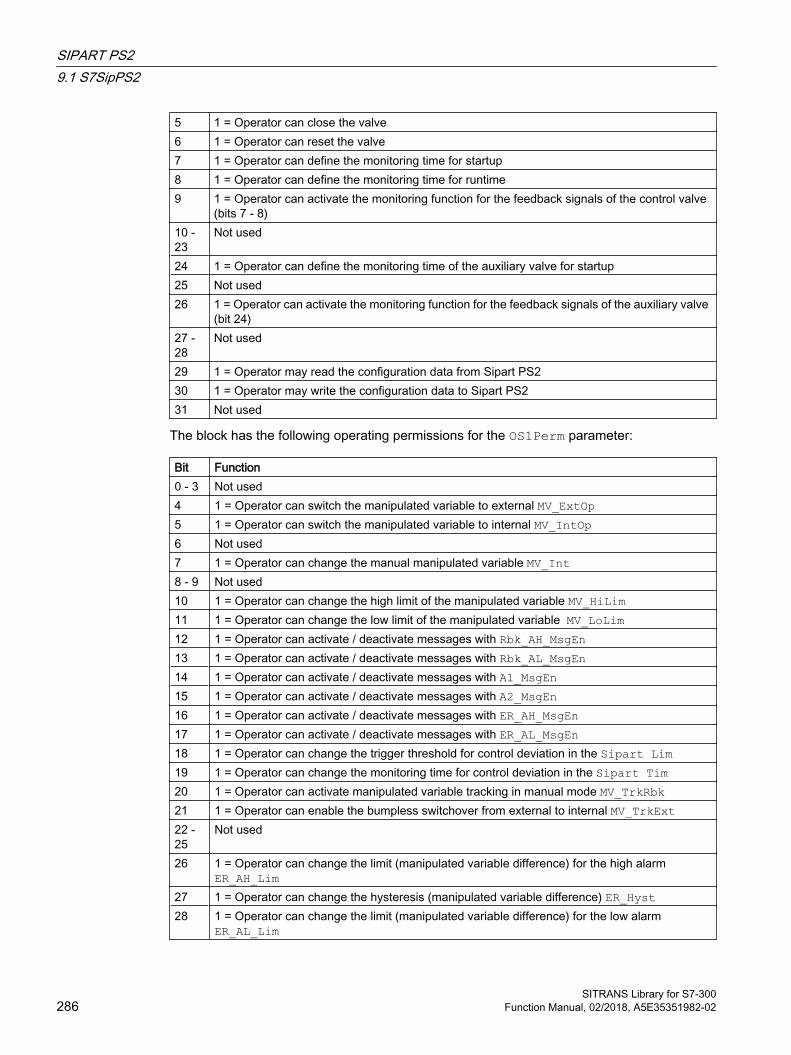
5 1 = Operator can close the valve6 1 = Operator can reset the valve7 1 = Operator can define the monitoring time for startup8 1 = Operator can define the monitoring time for runtime9 1 = Operator can activate the monitoring function for the feedback signals of the control valve
(bits 7 - 8)10 - 23
Not used
24 1 = Operator can define the monitoring time of the auxiliary valve for startup25 Not used26 1 = Operator can activate the monitoring function for the feedback signals of the auxiliary valve
(bit 24)27 - 28
Not used
29 1 = Operator may read the configuration data from Sipart PS230 1 = Operator may write the configuration data to Sipart PS231 Not used
The block has the following operating permissions for the OS1Perm parameter:
Bit Function0 - 3 Not used4 1 = Operator can switch the manipulated variable to external MV_ExtOp5 1 = Operator can switch the manipulated variable to internal MV_IntOp6 Not used7 1 = Operator can change the manual manipulated variable MV_Int8 - 9 Not used10 1 = Operator can change the high limit of the manipulated variable MV_HiLim11 1 = Operator can change the low limit of the manipulated variable MV_LoLim12 1 = Operator can activate / deactivate messages with Rbk_AH_MsgEn13 1 = Operator can activate / deactivate messages with Rbk_AL_MsgEn14 1 = Operator can activate / deactivate messages with A1_MsgEn15 1 = Operator can activate / deactivate messages with A2_MsgEn16 1 = Operator can activate / deactivate messages with ER_AH_MsgEn17 1 = Operator can activate / deactivate messages with ER_AL_MsgEn18 1 = Operator can change the trigger threshold for control deviation in the Sipart Lim19 1 = Operator can change the monitoring time for control deviation in the Sipart Tim20 1 = Operator can activate manipulated variable tracking in manual mode MV_TrkRbk21 1 = Operator can enable the bumpless switchover from external to internal MV_TrkExt22 - 25
Not used
26 1 = Operator can change the limit (manipulated variable difference) for the high alarm ER_AH_Lim
27 1 = Operator can change the hysteresis (manipulated variable difference) ER_Hyst28 1 = Operator can change the limit (manipulated variable difference) for the low alarm
ER_AL_Lim
SIPART PS29.1 S7SipPS2
SITRANS Library for S7-300286 Function Manual, 02/2018, A5E35351982-02

29 1 = The operator can change the limit (position feedback) for the high warning RbkWH_Lim30 1 = Operator can change the hysteresis (position feedback) RbkHyst31 1 = The operator can change the hysteresis (position feedback) for low warning RbkWL_Lim
Note
If you interconnect a parameter that is also listed in OS_Perm as a parameter, you have to reset the corresponding OS_Permbit.
Generation of manipulated variables The manipulated variable MV is formed as follows:
MV_ForOn
Close‐Force
Open‐Force
Man‐Act
Au‐tAct
MV = Limit State
1 0 0 - - MV_Forced None Forced tracking without limit
- 1 0 - - MV_OpScaleL MV_OpScaleL Forced close- 0 1 - - MV_OpScaleH MV_OpScaleH Forced open0 0 0 1 0 MV_Int MV_HiLim
MV_LoLimManual mode with internal ma‐nipulated variable
0 0 0 1 0 MV_ExtOut MV_HiLim MV_LoLim
Manual mode with external ma‐nipulated variable and limit
0 0 0 0 1 MV_Int MV_HiLim MV_LoLim
Automatic with external manipu‐lated variable and limit
0 0 0 0 1 MV_ExtOut MV_HiLim MV_LoLim
Automatic with external manipu‐lated variable and limit
0 0 0 - - MV_Trk MV_HiLim MV_LoLim
Tracking with limi‐tation
0 0 0 0 - Rbk None Tracking to posi‐tion feedback without limit
0 0 0 0 0 Rbk None Local mode with tracking to posi‐tion feedback without limit
SIPART PS29.1 S7SipPS2
SITRANS Library for S7-300Function Manual, 02/2018, A5E35351982-02 287

Local‐Act
MV_TrkOn
MV_TrkRbk
MV_Ex‐tAct
MV = Limit State
- - - - MV_Forced None Forced tracking without limit
- - - - MV_OpScaleL MV_OpScaleL Forced close- - - - MV_OpScaleH MV_OpScaleH Forced open0 0 - 0 MV_Int MV_HiLim
MV_LoLimManual mode with internal ma‐nipulated variable
0 0 - 1 MV_ExtOut MV_HiLim MV_LoLim
Manual mode with external ma‐nipulated varia‐ble and limit
0 0 - 1 MV_Int MV_HiLim MV_LoLim
Automatic with external manipu‐lated variable and limit
0 0 - 1 MV_ExtOut MV_HiLim MV_LoLim
Automatic with external manipu‐lated variable and limit
0 1 0 - MV_Trk MV_HiLim MV_LoLim
Tracking with lim‐itation
0 1 1 - Rbk None Tracking to posi‐tion feedback without limit
1 - - - Rbk None Local mode with tracking to posi‐tion feedback without limit
"Actuator active" information ● With PosReached.Value = 0, the following applies:
With PosDiClose < MV < PosDiOpen, the control valve is detected as active and bit 24 is set in Status1.
● The following applies to PosReached.Value = 1: Status1.Bit 24 = 0This status can be used to indicate a customized symbol in the process image, for example, and is saved in the status word (see Status word section in Description of S7SipPS2 (Page 271)).
General function "MV difference" The manipulated variable difference is sent to the ER output and is calculated with the following formula:
ER = MV - RbkIf ER is within the dead band, ER = 0 is set and the manipulated variable is considered reached.
SIPART PS29.1 S7SipPS2
SITRANS Library for S7-300288 Function Manual, 02/2018, A5E35351982-02

Manipulated variable difference generation and dead band
The manipulated variable difference is formed by the effective manipulated variable MV and the position feedback Rbk, and sent to the ER output. A dead band can be set at the PosDeadBand input:
● PosDeadBand = 0 Dead band is disabled
● PosDeadBand ≠ 0 Dead band is enabled
Limit monitoring of manipulated variable and control error This block provides the standard "Limit monitoring of the setpoint, manipulated variable and control error" function that is described in the APL Online Help.
Monitoring is disabled in the following situations:
● The auxiliary valve is closed
● The control valve is in the neutral position
Specifying warning times for control functions at motors and valves This block provides the standard "Specifying warning times for control functions with motors and valves" function that is described in the APL Online Help.
The warning time affect the analog manipulated variable MV. The output is updated only with the specification of a new manipulated variable after the warning time has expired.
Warning time is ignored in tracking MV_TrkOn = 1 and in forced tracking MV_ForOn.
Deactivate feedback This block provides the standard "Disabling feedback for valves" function that is described in the APL Online Help.
This function is available for both the control valve and auxiliary valve. The feedback for the auxiliary valve is disabled by default, connections are not displayed.
The disable setting is made with the NoFbkOpen and NoFbkClose parameters for the control valve.
SIPART PS29.1 S7SipPS2
SITRANS Library for S7-300Function Manual, 02/2018, A5E35351982-02 289
The disable setting is made with the NoFbkAuxVOpen and NoFbkAuxVClose parameters for the auxiliary valve.
Button labels This block provides the standard "Labeling buttons and texts" function that is described in the APL Online Help.
Instance-specific text can be configured for the following parameters:
● OpenMan● CloseMan
9.1.4 Error handling of S7SipPS2 For general information on error handling at all blocks, refer to the "Error handling" section in the APL Online Help.
The following errors can be displayed for this block:
● Error numbers
● Mode switchover error
● Invalid input signals
Overview of error numbers The ErrorNum I/O can be used to output the following error numbers:
Error number Meaning of the error number-1 Predefined value when inserting the block; the block is not executed.0 No active fault41 The value of the LocalSetting connection is outside the valid range. Valid values
are 0, 2 and 442 LocalSetting = 0 or LocalSetting = 4 and LocalLi = 151 AutModLi = 1 and ManModLi = 1
OpenAut = 1 and CloseAut = 1OpenForce = 1 and CloseForce = 1
52 LocalSetting = 2 or 4 and SimOn = 1
Mode switchover error This error can be output by the block, see the "Error handling" section in the APL Online Help.
Invalid input signals This error can be output by the block, see the "Error handling" section in the APL Online Help.
SIPART PS29.1 S7SipPS2
SITRANS Library for S7-300290 Function Manual, 02/2018, A5E35351982-02

9.1.5 S7SipPS2 messaging
Messaging The following messages can be generated for this block:
● Process control error
● Process messages
Process control error The following control system fault messages can be output:
Message in‐stance
Message class Event
MsgEvId01 PLC Process Control Message - Failure $$BlockComment$$ Feedback er‐ror (S7SipPS2: #@3X%3u@) [BatchID:@2X%3u@] [Auxiliary value:@1R%4.1f@]
MsgEvId06 PLC Process Control Message - Failure $$BlockComment$$ External error has occurred (S7SipPS2: #@3X%3u@) [BatchID:@2X%3u@] [Auxiliary value:@1R%4.1f@]
MsgEvId11 PLC Process Control Message - Failure $$BlockComment$$ Sipart - Fault (S7SipPS2: #@3X%3u@) [Batch‐ID:@2X%3u@] [Auxiliary val‐ue:@1R%4.1f@]
MsgEvId15 PLC Process Control Message - Error $$BlockComment$$ Error while reading configuration data (S7SipPS2: #@3X%3u@) [Batch‐ID:@2X%3u@] [Auxiliary val‐ue:@1R%4.1f@]
MsgEvId16 PLC Process Control Message - Error $$BlockComment$$ Error while writing configuration data (S7SipPS2: #@3X%3u@) [Batch‐ID:@2X%3u@] [Auxiliary val‐ue:@1R%4.1f@]
Explanation:
$$BlockComment$$: Content of the instance-specific comment
You can interconnect an external fault (signal) to input parameter CSF. If this signal changes to CSF = 1, a process control error is triggered (MsgEvId06).
SIPART PS29.1 S7SipPS2
SITRANS Library for S7-300Function Manual, 02/2018, A5E35351982-02 291

Process messages
Message in‐stance
Message class
Event
MsgEvId02 Alarm - high $$BlockComment$$ ER - High alarm limit violated (S7SipPS2: #@3X%3u@) [BatchID:@2X%3u@] [Auxiliary value:@1R%4.1f@]
MsgEvId03 Alarm - low $$BlockComment$$ ER - Low alarm limit violated (S7SipPS2: #@3X%3u@) [BatchID:@2X%3u@] [Auxiliary value:@1R%4.1f@]
MsgEvId04 Warning - high
$$BlockComment$$ Rbk - High limit violated (S7SipPS2: #@3X%3u@) [BatchID:@2X%3u@] [Auxiliary value:@1R%4.1f@]
MsgEvId05 Warning - low $$BlockComment$$ Rbk - Low limit violated (S7SipPS2: #@3X%3u@) [BatchID:@2X%3u@] [Auxiliary value:@1R%4.1f@]
MsgEvId07 Alarm - high $$BlockComment$$ Sipart - High alarm limit violated (S7SipPS2: #@3X%3u@) [BatchID:@2X%3u@] [Auxiliary value:@1R%4.1f@]
MsgEvId08 Warning - high
$$BlockComment$$ Sipart - High warning limit violated (S7SipPS2: #@3X%3u@) [BatchID:@2X%3u@] [Auxiliary value:@1R%4.1f@]
MsgEvId09 Warning - low $$BlockComment$$ Sipart - Low warning limit violated (S7SipPS2: #@3X%3u@) [BatchID:@2X%3u@] [Auxiliary value:@1R%4.1f@]
MsgEvId10 Alarm - low $$BlockComment$$ Sipart - Low alarm limit violated (S7SipPS2: #@3X%3u@) [BatchID:@2X%3u@] [Auxiliary value:@1R%4.1f@]
MsgEvId12 Alarm - high $$BlockComment$$ Sipart - Fail safe position (S7SipPS2: #@3X%3u@) [BatchID:@2X%3u@] [Auxiliary value:@1R%4.1f@]
MsgEvId13 Alarm - high $$BlockComment$$ Sipart - Emergency operation (S7SipPS2: #@3X%3u@) [BatchID:@2X%3u@] [Auxiliary value:@1R%4.1f@]
MsgEvId14 Alarm - high $$BlockComment$$ Sipart - Path integral exceeded (S7SipPS2: #@3X%3u@) [BatchID:@2X%3u@] [Auxiliary value:@1R%4.1f@]
Associated values
Associated value Block parameter Data Type1 Aux REAL2 BatchID DWORD3 MsgFilter DINT
9.1.6 S7SipPS2 connections
Input parameters
Parameter Description Type DefaultA1* Response threshold, alarm 1 (Si‐
part alarm module)REAL 0.0
A1Act 1 = Alarm 1 of alarm module ac‐tive
BOOL 0
A2* Response threshold, alarm 2 (Si‐part alarm module)
REAL 0.0
SIPART PS29.1 S7SipPS2
SITRANS Library for S7-300292 Function Manual, 02/2018, A5E35351982-02
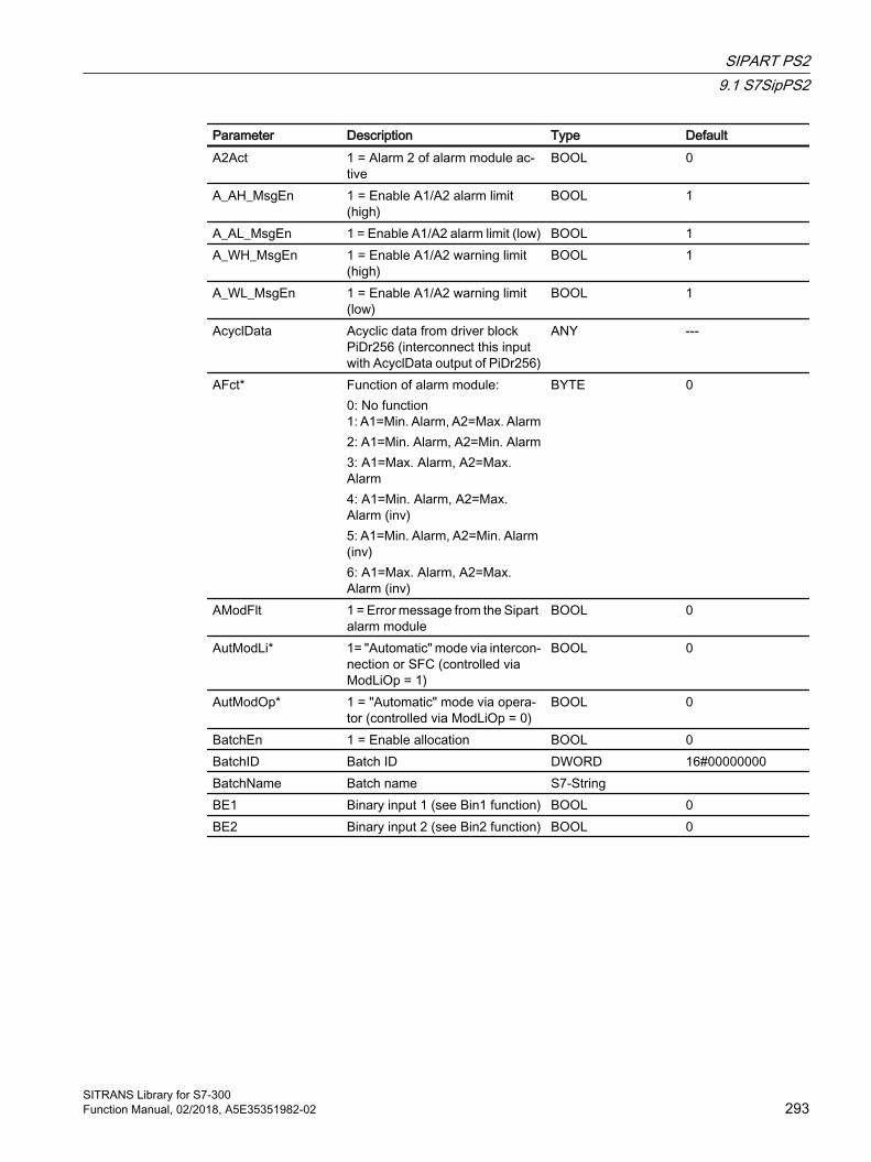
Parameter Description Type DefaultA2Act 1 = Alarm 2 of alarm module ac‐
tiveBOOL 0
A_AH_MsgEn 1 = Enable A1/A2 alarm limit (high)
BOOL 1
A_AL_MsgEn 1 = Enable A1/A2 alarm limit (low) BOOL 1A_WH_MsgEn 1 = Enable A1/A2 warning limit
(high)BOOL 1
A_WL_MsgEn 1 = Enable A1/A2 warning limit (low)
BOOL 1
AcyclData Acyclic data from driver block PiDr256 (interconnect this input with AcyclData output of PiDr256)
ANY ---
AFct* Function of alarm module:0: No function1: A1=Min. Alarm, A2=Max. Alarm2: A1=Min. Alarm, A2=Min. Alarm3: A1=Max. Alarm, A2=Max. Alarm4: A1=Min. Alarm, A2=Max. Alarm (inv)5: A1=Min. Alarm, A2=Min. Alarm (inv)6: A1=Max. Alarm, A2=Max. Alarm (inv)
BYTE 0
AModFlt 1 = Error message from the Sipart alarm module
BOOL 0
AutModLi* 1= "Automatic" mode via intercon‐nection or SFC (controlled via ModLiOp = 1)
BOOL 0
AutModOp* 1 = "Automatic" mode via opera‐tor (controlled via ModLiOp = 0)
BOOL 0
BatchEn 1 = Enable allocation BOOL 0BatchID Batch ID DWORD 16#00000000BatchName Batch name S7-String BE1 Binary input 1 (see Bin1 function) BOOL 0BE2 Binary input 2 (see Bin2 function) BOOL 0
SIPART PS29.1 S7SipPS2
SITRANS Library for S7-300Function Manual, 02/2018, A5E35351982-02 293

Parameter Description Type DefaultBin1* Function of the binary input BE1:
0: No function1: Message only (NCC)2: Message only (NOC)3: Block configuration (NOC)4: Block configuration and man‐ual (NOC)5: Travel valve to position YE (NOC)6: Travel valve to position YA (NOC)7: Block movement (NOC)8: Travel valve to position YE (NCC)9: Travel valve to position YA (NCC)10: Block movement (NCC)11: Partial stroke test (NOC)12: Partial stroke test (NCC)
BYTE 0
Bin2* Function of the binary input BE1:0: No function1: Message only (NCC)2: Message only (NOC)3: Travel valve to position YE (NOC)4: Travel valve to position YA (NOC)5: Block movement (NOC)6: Travel valve to position YE (NCC)7: Travel valve to position YA (NCC)8: Block movement (NCC)9: Partial stroke test (NOC)10: Partial stroke test (NCC)
BYTE 0
BypProt 1 = Bypassing interlock is active in "local mode" and in simulation
BOOL 0
Cbk0 1 = Sipart in fail-safe position BOOL 0Cbk1 1 = Request for "local operation" BOOL 0Cbk16 1 = Stroke integral exceeded BOOL 0Cbk2 1 = Sipart is operated locally BOOL 0Cbk3 1 = Emergency operation is active BOOL 0Cbk7 1 = Maximum permitted controller
monitoring exceeded (Lim/Tim)BOOL 0
CloseAut* 1 = Select Close valve in "auto‐matic mode"
BOOL 0
SIPART PS29.1 S7SipPS2
SITRANS Library for S7-300294 Function Manual, 02/2018, A5E35351982-02
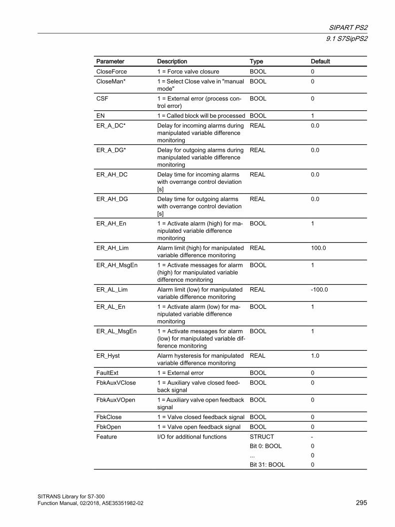
Parameter Description Type DefaultCloseForce 1 = Force valve closure BOOL 0CloseMan* 1 = Select Close valve in "manual
mode"BOOL 0
CSF 1 = External error (process con‐trol error)
BOOL 0
EN 1 = Called block will be processed BOOL 1ER_A_DC* Delay for incoming alarms during
manipulated variable difference monitoring
REAL 0.0
ER_A_DG* Delay for outgoing alarms during manipulated variable difference monitoring
REAL 0.0
ER_AH_DC Delay time for incoming alarms with overrange control deviation [s]
REAL 0.0
ER_AH_DG Delay time for outgoing alarms with overrange control deviation [s]
REAL 0.0
ER_AH_En 1 = Activate alarm (high) for ma‐nipulated variable difference monitoring
BOOL 1
ER_AH_Lim Alarm limit (high) for manipulated variable difference monitoring
REAL 100.0
ER_AH_MsgEn 1 = Activate messages for alarm (high) for manipulated variable difference monitoring
BOOL 1
ER_AL_Lim Alarm limit (low) for manipulated variable difference monitoring
REAL -100.0
ER_AL_En 1 = Activate alarm (low) for ma‐nipulated variable difference monitoring
BOOL 1
ER_AL_MsgEn 1 = Activate messages for alarm (low) for manipulated variable dif‐ference monitoring
BOOL 1
ER_Hyst Alarm hysteresis for manipulated variable difference monitoring
REAL 1.0
FaultExt 1 = External error BOOL 0FbkAuxVClose 1 = Auxiliary valve closed feed‐
back signalBOOL 0
FbkAuxVOpen 1 = Auxiliary valve open feedback signal
BOOL 0
FbkClose 1 = Valve closed feedback signal BOOL 0FbkOpen 1 = Valve open feedback signal BOOL 0Feature I/O for additional functions STRUCT
Bit 0: BOOL...Bit 31: BOOL
-000
SIPART PS29.1 S7SipPS2
SITRANS Library for S7-300Function Manual, 02/2018, A5E35351982-02 295
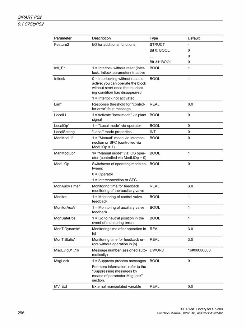
Parameter Description Type DefaultFeature2 I/O for additional functions STRUCT
Bit 0: BOOL...Bit 31: BOOL
-000
Intl_En 1 = Interlock without reset (inter‐lock, Intlock parameter) is active
BOOL 1
Intlock 0 = Interlocking without reset is active; you can operate the block without reset once the interlock‐ing condition has disappeared1 = Interlock not activated
BOOL 1
Lim* Response threshold for "control‐ler error" fault message
REAL 0.0
LocalLi 1 = Activate "local mode" via plant signal
BOOL 0
LocalOp* 1 = "Local mode" via operator BOOL 0LocalSetting "Local" mode properties INT 0ManModLi* 1 = "Manual" mode via intercon‐
nection or SFC (controlled via ModLiOp = 1)
BOOL 0
ManModOp* 1= "Manual mode" via: OS oper‐ator (controlled via ModLiOp = 0)
BOOL 1
ModLiOp Switchover of operating mode be‐tween: 0 = Operator1 = Interconnection or SFC
BOOL 0
MonAuxVTime* Monitoring time for feedback monitoring of the auxiliary valve
REAL 3.0
Monitor 1 = Monitoring of control valve feedback
BOOL 1
MonitorAuxV 1 = Monitoring of auxiliary valve feedback
BOOL 1
MonSafePos 1 = Go to neutral position in the event of monitoring errors
BOOL 1
MonTiDynamic* Monitoring time after operation in [s]
REAL 3.0
MonTiStatic* Monitoring time for feedback er‐rors without operation in [s]
REAL 3.0
MsgEvId01..16 Message number (assigned auto‐matically)
DWORD 16#00000000
MsgLock 1 = Suppress process messages.For more information, refer to the "Suppressing messages by means of parameter MsgLock" section.
BOOL 0
MV_Ext External manipulated variable REAL 0.0
SIPART PS29.1 S7SipPS2
SITRANS Library for S7-300296 Function Manual, 02/2018, A5E35351982-02

Parameter Description Type DefaultMV_ExtLi Select external manipulated vari‐
able (via interconnection)BOOL 0
MV_ExtOp* Select external manipulated vari‐able (via operator)
BOOL 0
MV_Forced Forced manipulated variable that is not limited and assumes top priority
REAL 0.0
MV_ForOn 1 = Forced manipulated variable MV_Forced is output unlimited at output MV
BOOL 0
MV_HiLim Limit (high) for manipulated vari‐able MV
REAL 100.0
MV_Int* Internal manipulated variable REAL 0.0MV_IntLi Select internal manipulated varia‐
ble (via interconnection)BOOL 0
MV_IntOp* Select internal manipulated varia‐ble (via operator)
BOOL 1
MV_LiOp Select manipulated variable source (internal/external):1 = Via interconnection0 = Via operator
BOOL 0
MV_LoLim Limit (low) for manipulated varia‐ble MV
REAL 0.0
MV_OpScaleH OS display range for manipulated variable MV
REAL 100.0
MV_OpScaleL OS display range for manipulated variable MV
REAL 0.0
MV_Trk Tracking value for manipulated variable MV
REAL 0.0
MV_TrkExt 1 = Bumpless switchover from ex‐ternal to internal manipulated var‐iable active
BOOL 0
MV_TrkOn 1 = Tracking of manipulated vari‐able MV
BOOL 0
MV_TrkRbk 1 = Bumpless switchover of ma‐nipulated variable tracking active (track manipulated variable to po‐sition feedback)
BOOL 0
MV_Unit Unit of measure for manipulated variable
INT 1342
NoFbkAuxVClose 1 = No "closed" feedback for aux‐iliary valve present
BOOL 1
NoFbkAuxVOpen 1 = No "open" feedback for auxil‐iary valve present
BOOL 1
NoFbkClose 1 = No feedback present for "con‐trol valve closed"
BOOL 0
NoFbkOpen 1 = No feedback present for "con‐trol valve open"
BOOL 0
SIPART PS29.1 S7SipPS2
SITRANS Library for S7-300Function Manual, 02/2018, A5E35351982-02 297

Parameter Description Type DefaultOccupied 1 = In use by a batch BOOL 0OosLi 1 = "Out of service", via intercon‐
nection or SFCBOOL 0
OosOp* 1 = "Out of service", via OS oper‐ator
BOOL 0
OpenAut* 1 = Select Open valve in "auto‐matic mode"
BOOL 0
OpenForce 1 = Forced open of control valve BOOL 0OpenMan* 1 = Select Open valve in "manual
mode"BOOL 0
OS_Perm I/O for operating permissions STRUCTBit 0: BOOLBit 12: BOOLBit 31: BOOL
-111
OS1Perm I/O for operating permissions STRUCTBit 0: BOOL...Bit 31: BOOL
-111
PosDeadBand Dead band for forming manipu‐lated variable difference
REAL 0.1
PosDiClose Limit for control valve position "closed"
REAL 5.0
PosDiOpen Limit for control valve position "open"
REAL 95.0
Rbk Position feedback for display on OS
REAL 0.0
QCRbk Qualty code of Position feedback for display on OS
REAL 0.0
RbkHyst Alarm hysteresis for position feed‐back
REAL 1.0
Rbk_WH_DC* Delay time for incoming warning message of the position feedback with overrange/underrange proc‐ess value or only with underrange process value [s]
REAL 0.0
Rbk_WH_DG* Delay time for outgoing warning message of the position feedback with overrange/underrange proc‐ess value or only with underrange process value [s]
REAL 0.0
Rbk_W_DC* Delay time for incoming warning of the position feedback with over‐range/underrange process value or only with underrange process value [s]
REAL 0.0
SIPART PS29.1 S7SipPS2
SITRANS Library for S7-300298 Function Manual, 02/2018, A5E35351982-02
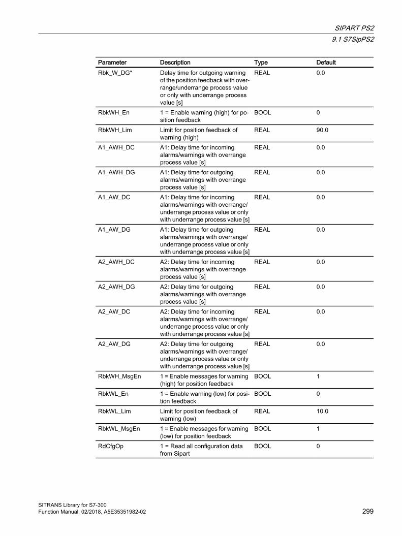
Parameter Description Type DefaultRbk_W_DG* Delay time for outgoing warning
of the position feedback with over‐range/underrange process value or only with underrange process value [s]
REAL 0.0
RbkWH_En 1 = Enable warning (high) for po‐sition feedback
BOOL 0
RbkWH_Lim Limit for position feedback of warning (high)
REAL 90.0
A1_AWH_DC A1: Delay time for incoming alarms/warnings with overrange process value [s]
REAL 0.0
A1_AWH_DG A1: Delay time for outgoing alarms/warnings with overrange process value [s]
REAL 0.0
A1_AW_DC A1: Delay time for incoming alarms/warnings with overrange/underrange process value or only with underrange process value [s]
REAL 0.0
A1_AW_DG A1: Delay time for outgoing alarms/warnings with overrange/underrange process value or only with underrange process value [s]
REAL 0.0
A2_AWH_DC A2: Delay time for incoming alarms/warnings with overrange process value [s]
REAL 0.0
A2_AWH_DG A2: Delay time for outgoing alarms/warnings with overrange process value [s]
REAL 0.0
A2_AW_DC A2: Delay time for incoming alarms/warnings with overrange/underrange process value or only with underrange process value [s]
REAL 0.0
A2_AW_DG A2: Delay time for outgoing alarms/warnings with overrange/underrange process value or only with underrange process value [s]
REAL 0.0
RbkWH_MsgEn 1 = Enable messages for warning (high) for position feedback
BOOL 1
RbkWL_En 1 = Enable warning (low) for posi‐tion feedback
BOOL 0
RbkWL_Lim Limit for position feedback of warning (low)
REAL 10.0
RbkWL_MsgEn 1 = Enable messages for warning (low) for position feedback
BOOL 1
RdCfgOp 1 = Read all configuration data from Sipart
BOOL 0
SIPART PS29.1 S7SipPS2
SITRANS Library for S7-300Function Manual, 02/2018, A5E35351982-02 299
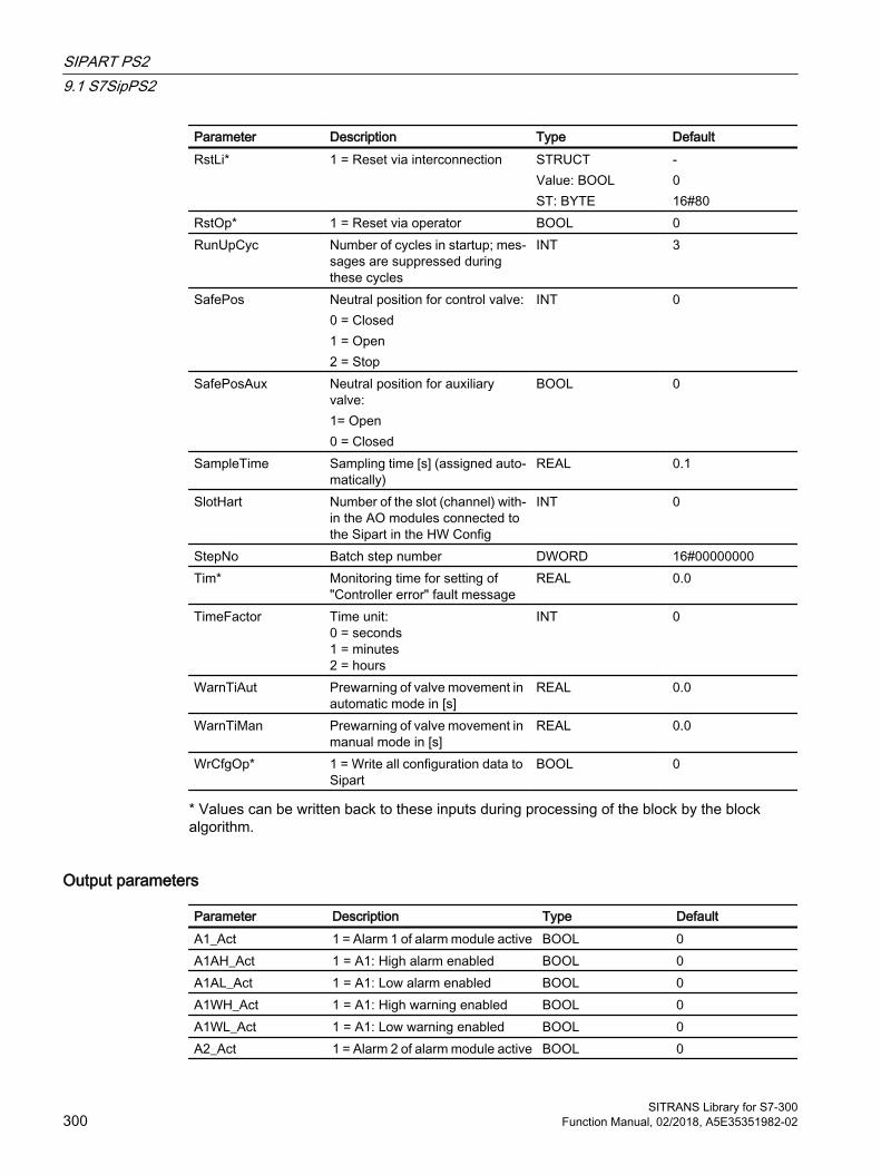
Parameter Description Type DefaultRstLi* 1 = Reset via interconnection STRUCT
Value: BOOLST: BYTE
-016#80
RstOp* 1 = Reset via operator BOOL 0RunUpCyc Number of cycles in startup; mes‐
sages are suppressed during these cycles
INT 3
SafePos Neutral position for control valve:0 = Closed1 = Open2 = Stop
INT 0
SafePosAux Neutral position for auxiliary valve:1= Open0 = Closed
BOOL 0
SampleTime Sampling time [s] (assigned auto‐matically)
REAL 0.1
SlotHart Number of the slot (channel) with‐in the AO modules connected to the Sipart in the HW Config
INT 0
StepNo Batch step number DWORD 16#00000000Tim* Monitoring time for setting of
"Controller error" fault messageREAL 0.0
TimeFactor Time unit:0 = seconds1 = minutes2 = hours
INT 0
WarnTiAut Prewarning of valve movement in automatic mode in [s]
REAL 0.0
WarnTiMan Prewarning of valve movement in manual mode in [s]
REAL 0.0
WrCfgOp* 1 = Write all configuration data to Sipart
BOOL 0
* Values can be written back to these inputs during processing of the block by the block algorithm.
Output parameters
Parameter Description Type DefaultA1_Act 1 = Alarm 1 of alarm module active BOOL 0A1AH_Act 1 = A1: High alarm enabled BOOL 0A1AL_Act 1 = A1: Low alarm enabled BOOL 0A1WH_Act 1 = A1: High warning enabled BOOL 0A1WL_Act 1 = A1: Low warning enabled BOOL 0A2_Act 1 = Alarm 2 of alarm module active BOOL 0
SIPART PS29.1 S7SipPS2
SITRANS Library for S7-300300 Function Manual, 02/2018, A5E35351982-02

Parameter Description Type DefaultA2AH_Act 1 = A2: High alarm enabled BOOL 0A2AL_Act 1 = A2: Low alarm enabled BOOL 0A2WH_Act 1 = A2: High warning enabled BOOL 0A2WL_Act 1 = A2: Low warning enabled BOOL 0AModFlt_Act 1 = Fault message of alarm mod‐
ule activeBOOL 0
AutAct 1 = "Automatic mode" enabled0 = "Manual mode", "Local mode" or "Out of service" enabled
BOOL 0
AuxClosed 1 = Auxiliary valve is closed BOOL 0AuxClsing 1 = Auxiliary valve is closing BOOL 0AuxOpened 1 = Valve is open BOOL 0AuxOpning 1 = Auxiliary valve is opening BOOL 0CascaCut Cascade connection:
1 = Control chain from master con‐troller to secondary valve is inter‐rupted
BOOL 0
Ctrl Control output for auxiliary valve (depends on SafePosAuxV)
BOOL 0
Closed 1 = Valve is closed BOOL 0Closing 1 = Valve is closing BOOL 0ENO 1 = Block algorithm completed
without errorsBOOL 0
EmergOp_Act 1 = Emergency operation is active (Cbk3)
BOOL 0
ER Manipulated variable difference REAL 0.0ER_AH_Act 1 = Alarm limit (high) for manipu‐
lated variable difference violated. You can change the response for this parameter by setting Feature bit 28 (deactivate switching points) and Feature bit 29 (high/low signal limit violation) accordingly.
BOOL 0
ER_AL_Act 1 = Alarm limit (low) for manipu‐lated variable difference violated. You can change the response for this parameter by setting Feature bit 28 (deactivate switching points) and Feature bit 29 (high/low signal limit violation) accordingly.
BOOL 0
ErrorNum Output of current error number. For error numbers that can be out‐put by this block, see the error handling of VlvAnL
INT -1
SIPART PS29.1 S7SipPS2
SITRANS Library for S7-300Function Manual, 02/2018, A5E35351982-02 301

Parameter Description Type DefaultFailSav_Act 1 = Field device in fail-safe posi‐
tion (Cbk0)BOOL 0
FbkAuxVCloseOut 1 = Auxiliary valve is closed BOOL 0FbkAuxVOpenOut 1 = Auxiliary valve is open BOOL 0FbkCloseOut 1 = Control valve is open BOOL 0FbkClsgOut Control valve closing feedback BOOL 0FbkOpenOut 1 = Control valve is open BOOL 0FbkOpngOut Control valve opening feedback BOOL 0GrpErr 1 = Group error pending BOOL 0LocalAct 1 = "Local mode" enabled BOOL 0LockAct 1 = Interlock is active BOOL 0ManAct 1 = "Manual mode" enabled BOOL 1MsgStat01..16 Message status WORD 16#0000MsgAck01..16 Message acknowledgment status BOOL 0MonDynAuxVErr 1 = Feedback error auxiliary valve
due to output changeBOOL 0
MonDynErr 1 = Feedback error control valve due to control change
BOOL 0
MonStaAuxVErr 1 = Feedback error from auxiliary valve due to unexpected feedback change
BOOL 0
MonStaErr 1 = Feedback error from control valve due to unexpected feedback change
BOOL 0
MV Manipulated variable REAL 0.0QCMV Quality code of manipulated vari‐
ableBYTE 0
MV_ExtAct 1 = External manipulated variable active0 = Internal manipulated variable active
BOOL 0
MV_ExtOut Output for external manipulated variable
REAL 0.0
MV_HiAct 1 = Limit (high) of manipulated var‐iable violated
BOOL 0
MV_LoAct 1 = Limit (low) of manipulated var‐iable violated
BOOL 0
MV_RateTarget Target manipulated variable for the gradient limitation
REAL 0.0
MV_UnitOut Unit of measure for manipulated variable
INT 0
OosAct 1 = Block is "Out of service" BOOL 0Opened 1 = Valve is open BOOL 0Opening 1 = Valve is opening BOOL 0
SIPART PS29.1 S7SipPS2
SITRANS Library for S7-300302 Function Manual, 02/2018, A5E35351982-02

Parameter Description Type DefaultOS_PermLog Display of OS_Perm with settings
changed by the block algorithmDWORD 16#FFFFFFFF
OS_PermOut Display of OS_Perm DWORD 16#FFFFFFFFOS1PermLog Display of OS1Perm with settings
changed by the block algorithmDWORD 16#FFFFFFFF
OS1PermOut Display of OS1Perm DWORD 16#FFFFFFFFP_Rst 1= Pulse output for reset
The parameter persists for one cy‐cle after a reset.
BOOL 0
PIExeed_Act 1 = Stoke integral exceeded (Cbk16)
BOOL 0
PosReached 1 = Control valve has reached specified position
BOOL 0
QLim Response threshold for "controller error" fault message
REAL 0.0
QTim Monitoring time for setting of "Con‐troller error" fault message
REAL 0.0
QWronDev 1 = Wrong device connected BOOL 1RbkOut Position feedback output REAL 0.0RbkWH_Act 1 = Warning (high) active.
You can change the response for this parameter by setting Feature bit 28 (deactivate switching points) and Feature bit 29 (high/low signal limit violation) accordingly.
BOOL 0
RbkWL_Act 1 = Warning (low) active. You can change the response for this parameter by setting Feature bit 28 (deactivate switching points) and Feature bit 29 (high/low signal limit violation) accordingly.
BOOL 0
RdyToReset 1 = Ready for reset via RstLi input or commands in "automatic mode"
BOOL 0
RdyToStart 1 = Active start readiness BOOL 0Status1 Status word 1 DWORD 16#00000000Status2 Status word 2 DWORD 16#00000000Status3 Status word 3 DWORD 16#00000000Status4 Status word 4 DWORD 16#00000000Status5 Status word 5 DWORD 16#00000000Status6 Status word 6 DWORD 16#00000000SumMsgAct 1 = Group message active BOOL 0WarnAct 1 = Prewarning for control valve
movement away from neutral po‐sition active (WarnTiAut and WarnTiMan parameters)
BOOL 0
SIPART PS29.1 S7SipPS2
SITRANS Library for S7-300Function Manual, 02/2018, A5E35351982-02 303
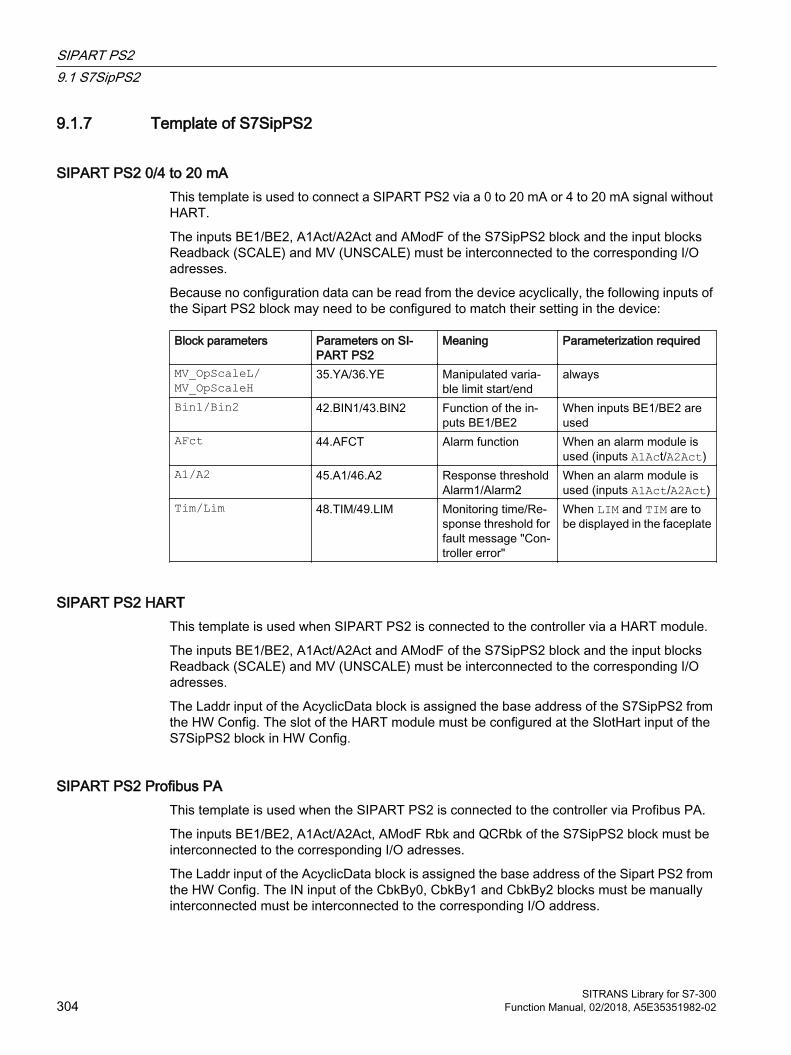
9.1.7 Template of S7SipPS2
SIPART PS2 0/4 to 20 mAThis template is used to connect a SIPART PS2 via a 0 to 20 mA or 4 to 20 mA signal without HART.
The inputs BE1/BE2, A1Act/A2Act and AModF of the S7SipPS2 block and the input blocks Readback (SCALE) and MV (UNSCALE) must be interconnected to the corresponding I/O adresses.
Because no configuration data can be read from the device acyclically, the following inputs of the Sipart PS2 block may need to be configured to match their setting in the device:
Block parameters Parameters on SI‐PART PS2
Meaning Parameterization required
MV_OpScaleL/ MV_OpScaleH
35.YA/36.YE Manipulated varia‐ble limit start/end
always
Bin1/Bin2 42.BIN1/43.BIN2 Function of the in‐puts BE1/BE2
When inputs BE1/BE2 are used
AFct 44.AFCT Alarm function When an alarm module is used (inputs A1Act/A2Act)
A1/A2 45.A1/46.A2 Response threshold Alarm1/Alarm2
When an alarm module is used (inputs A1Act/A2Act)
Tim/Lim 48.TIM/49.LIM Monitoring time/Re‐sponse threshold for fault message "Con‐troller error"
When LIM and TIM are to be displayed in the faceplate
SIPART PS2 HARTThis template is used when SIPART PS2 is connected to the controller via a HART module.
The inputs BE1/BE2, A1Act/A2Act and AModF of the S7SipPS2 block and the input blocks Readback (SCALE) and MV (UNSCALE) must be interconnected to the corresponding I/O adresses.
The Laddr input of the AcyclicData block is assigned the base address of the S7SipPS2 from the HW Config. The slot of the HART module must be configured at the SlotHart input of the S7SipPS2 block in HW Config.
SIPART PS2 Profibus PA This template is used when the SIPART PS2 is connected to the controller via Profibus PA.
The inputs BE1/BE2, A1Act/A2Act, AModF Rbk and QCRbk of the S7SipPS2 block must be interconnected to the corresponding I/O adresses.
The Laddr input of the AcyclicData block is assigned the base address of the Sipart PS2 from the HW Config. The IN input of the CbkBy0, CbkBy1 and CbkBy2 blocks must be manually interconnected must be interconnected to the corresponding I/O address.
SIPART PS29.1 S7SipPS2
SITRANS Library for S7-300304 Function Manual, 02/2018, A5E35351982-02
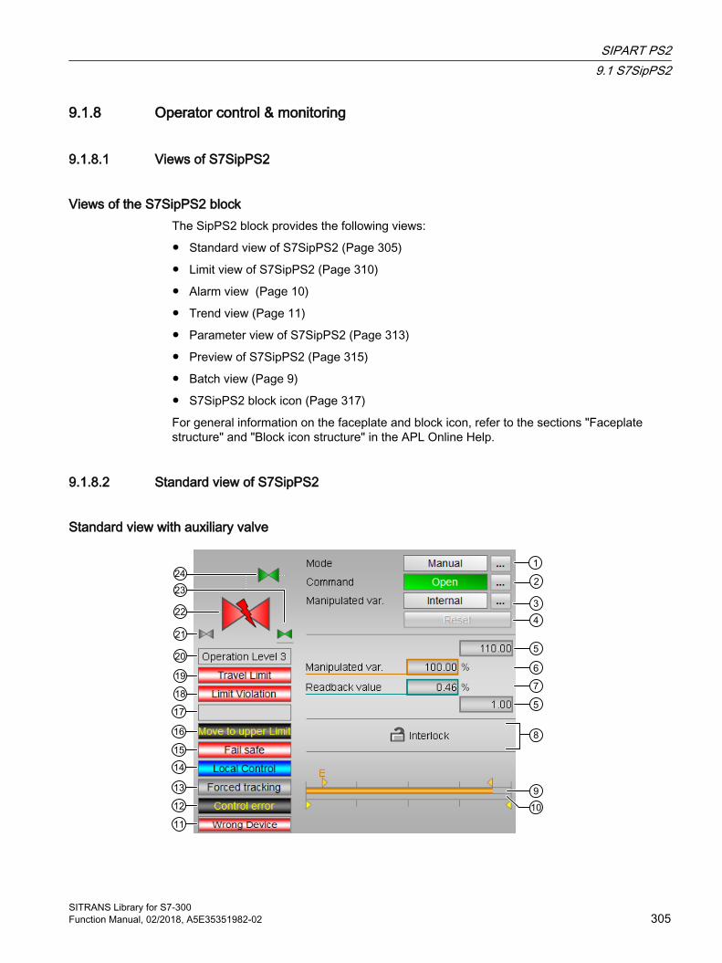
9.1.8 Operator control & monitoring
9.1.8.1 Views of S7SipPS2
Views of the S7SipPS2 blockThe SipPS2 block provides the following views:
● Standard view of S7SipPS2 (Page 305)
● Limit view of S7SipPS2 (Page 310)
● Alarm view (Page 10)
● Trend view (Page 11)
● Parameter view of S7SipPS2 (Page 313)
● Preview of S7SipPS2 (Page 315)
● Batch view (Page 9)
● S7SipPS2 block icon (Page 317)
For general information on the faceplate and block icon, refer to the sections "Faceplate structure" and "Block icon structure" in the APL Online Help.
9.1.8.2 Standard view of S7SipPS2
Standard view with auxiliary valve
SIPART PS29.1 S7SipPS2
SITRANS Library for S7-300Function Manual, 02/2018, A5E35351982-02 305

(1) Display and switch the operating modeThis area provides information on the currently valid operating mode. The following operating modes can be shown here:
● Manual mode (see the APL Online Help)
● Automatic mode (see the APL Online Help)
● Local mode (see the APL Online Help)
● Out of service (see APL Online Help)
For more information on switching over of the operating mode, refer to the "Switchover of operating state and operating mode" section in the APL Online Help.
(2) Opening, closing and stopping the control valveThis area shows you the default operating state for the valve. The following states can be shown and executed here:
● "Open"
● "Close"
● "Stop" (display only, no operation possible)
"Close"/"open" command relates to the auxiliary valve. If no auxiliary valve is required for controlling the control valve, the "Open" and "Close" commands affect the control valve.
If text is configured for these commands, it is displayed as status text and as button labels for command selection. You can find additional information on this in the "Labeling buttons and texts" section in the APL Online Help.
For more information on switching over of the state, refer to the "Switchover of operating state and operating mode" section in the APL Online Help.
(3) Displaying and switching the default manipulated variableThis area shows how to specify the manipulated variable. The manipulated variable can be specified as follows:
● By the application ("External", CFC/SFC)
● By the user directly in the faceplate ("Internal").
For more information on switching over of the manipulated variable specification, refer to the "Switchover of operating state and operating mode" section in the APL Online Help.
(4) Resetting the blockClick "Reset" for interlocks or errors. For more information, refer to the "Resetting the block in case of interlocks or errors" section in the APL Online Help.
(5) High and low scale range for the manipulated variableThese values provide information on the display range for the bar graph of the manipulated variable. The scale range is defined on the Sipart and read by the block there.
SIPART PS29.1 S7SipPS2
SITRANS Library for S7-300306 Function Manual, 02/2018, A5E35351982-02
(6) Displaying and changing the manipulated variableThis area shows the current manipulated variable.
The manipulated variable can only be changed by
● Internal manipulated variable specification (MV_ExtAct = 0) and
● an open auxiliary valve (due to the dependence on the standard function "Neutral position for motors, valves and controllers" that is described in the APL Online Help).
For more information about changing the manipulated variable, see the "Changing values" section in the APL Online Help.
(7) Display of the position feedback including signal statusThis area shows the current feedback of the manipulated variable with the corresponding signal status.
(8) Operating area for the interlock functions of the blockThis display is only visible when the corresponding block input is connected.
You can use this button to control the interlock functions of the block. For more information, refer to the "Interlock functions" section in the APL Online Help.
The following is displayed in addition to the buttons:
● Interlock status (see "Forming the group status for interlock information" section in the APL Online Help), for example:
(9) Bar graph for the manipulated variableThis area shows the current manipulated variable in the form of a bar graph. The visible area in the bar graph depends on the configuration in the Engineering System (ES).
The external manipulated variable is identified by the letter "E".
(10) Bar graph for position feedbackThe dosing quantity can only be reset in the "End" status.
(11) Display area for block states● "Wrong device"
(12) Display area for block statesThis area provides additional information on the operating state of the block:
● “Error End position”
● "Control error"
SIPART PS29.1 S7SipPS2
SITRANS Library for S7-300Function Manual, 02/2018, A5E35351982-02 307
● "Invalid signal"
● "Changeover error"
Additional information on these errors is available in the sections "Monitoring the feedbacks, Error handling", (subsection "Invalid input signals" and "Mode switchover error") in the APL Online Help.
(13) Display area for block statesThis area provides additional information on the operating state of the block:
● "Forced open" (OpenForce)
● "Forced close" (CloseForce)
● "Forced tracking" (MV_ForOn)
● "Tracking" (MV_TrkOn)
● "Request 0/1": A reset to "automatic mode" is expected.
For more information, refer to the "Forcing operating states" section in the APL Online Help.
(14) Display area for state of the Sipart PS2This area provides additional information on the Sipart PS2 module:
● "Local operation"
(15) Display area for state of the Sipart PS2This area provides additional information on the Sipart PS2 module:
● "Fail-safe position"
(16) Display area for state of the binary input BE2This area provides additional information on the binary input BE2 according to the configuration of Bin2:
● "Message Bin2"
● "Travel to end value"
● "Travel to start value"
● "Movement blocked"
● "PST" (Partial-Stroke-Test)
SIPART PS29.1 S7SipPS2
SITRANS Library for S7-300308 Function Manual, 02/2018, A5E35351982-02
(17) Display area for state of the binary input BE1This area provides additional information on the binary input BE1 according to the configuration of Bin1:
● "Message Bin1"
● "Configuration change blocked"
● "Configuration change blocked/Manual mode"
● "Travel to end value"
● "Travel to start value"
● "Movement blocked"
● "PST" (Partial-Stroke-Test)
(18) Display area for block statesThis area provides additional information on the operating state of the block:
● "Limit violated"
(19) Display area for state of the Sipart PS2This area provides additional information on the Sipart PS2 module:
● "Stroke integral exceeded"
(20) Display area for switch permissionThis area provides the text of the current OS, according to the enumeration configured at the PERMIS input.
(21) Automatic previewThis display is only visible in "manual mode", in "local mode", or with a reset request in "automatic mode", when the current output signals are not identical to the control in "automatic mode".
The display shows what state the valve would assume if you switched from "manual" or "local" mode to "automatic mode", or performed a reset to "automatic mode".
(22) Status display of the control valveYou can find additional information on this in section S7SipPS2 block icon (Page 317).
SIPART PS29.1 S7SipPS2
SITRANS Library for S7-300Function Manual, 02/2018, A5E35351982-02 309
(23) Representation of neutral positionThis representation shows the neutral position for the control valve:
● Green: Neutral position is "Open"
● Gray: Neutral position is "Closed"
● Light green: Neutral position is "Stop"
(24) Picture of auxiliary valveThe small auxiliary valve and the associated line are only shown when the control valve has an additional auxiliary valve and it can be controlled. Configurable with Feature bit 5 at the block.
The current status of the auxiliary valve is graphically displayed here.
9.1.8.3 Limit view of S7SipPS2Several values can be set by default in this view:
● Manipulated variable difference limits
● Readback value limits
● Manipulated variable operating range
The toolbars of the faceplate and the block icon indicate when the limits are reached or violated.
SIPART PS29.1 S7SipPS2
SITRANS Library for S7-300310 Function Manual, 02/2018, A5E35351982-02

(1) Enabled operationsThis area shows all operations for which special operator authorizations are assigned. They depend on the configuration in the engineering system (ES) that applies to this block.
Symbols for enabled operations:
● Green check mark: The OS operator can control this parameter
● Gray check mark: the OS operator cannot control this parameter at this time due to the process
● Red cross: The OS operator cannot control this parameter due to the configured AS operator permissions (OS_Perm or OS1Perm)
(2) Actual value limits (Sipart alarm module)The limits displayed here are the limits of the optional Sipart PS2 alarm module. You cannot change the values in the faceplate. Depending on the configuration of the alarm module ( Afct input), the alarm limits (A1, A2) are shown as alarm high/low, alarm/warning high or alarm/warning low. The associated messages in WinCC are triggered by setting the inputs A1Act and A2Act.
SIPART PS29.1 S7SipPS2
SITRANS Library for S7-300Function Manual, 02/2018, A5E35351982-02 311

(3) Limit and monitoring time manipulated variable difference (Sipart)This area displays and may allow you to change the limit for the maximum manipulated variable difference (LIM) and the monitoring time (TIM) which must deviate from the manipulated variable before a fault message is triggered in the device. In the event of a limit violation, the general message "Sipart error" is output in WinCC.
If the limits LIM and TIM are not to be displayed, the Feature2.Bit3 must be set to FALSE.
(4) Manipulated variable difference limitsIn this area, you can enter the limits for the manipulated variable error. Refer to the "Changing values" section in the APL Online Help.
You can change the following limits:
● "H alarm": High alarm
● "Hysteresis"
● "L alarm": Low alarm
(5) Readback value limits (MV)In this area, you can enter the limits for the readback value (position feedback). Refer to the "Changing values" section in the APL Online Help.
You can change the following limits:
● "H warning": High warning
● "Hysteresis"
● "L warning": Low warning
(6) Manipulated variable operating range (MV)In this area, you can enter the limits for the manipulated variable operation range. Refer to the "Changing values" section in the APL Online Help.
You can change the following limits:
● "H range": Range limit high
● "L range": Range limit low
(7) Message suppression/delaysThe message suppression indicates whether suppression of the associated message is activated in the AS block using the xx_MsgEn parameter. The output of messages is not suppressed when the block is installed (all xx_MsgEn parameters are set to 1 by default). Messages can only be output if limit monitoring of the additional analog value has been enabled.
Alarm delays are also displayed in this state; refer to the "Application of alarm delays" section in the APL Online Help.
SIPART PS29.1 S7SipPS2
SITRANS Library for S7-300312 Function Manual, 02/2018, A5E35351982-02
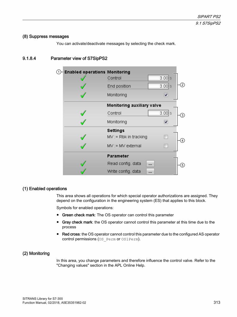
(8) Suppress messagesYou can activate/deactivate messages by selecting the check mark.
9.1.8.4 Parameter view of S7SipPS2
(1) Enabled operationsThis area shows all operations for which special operator authorizations are assigned. They depend on the configuration in the engineering system (ES) that applies to this block.
Symbols for enabled operations:
● Green check mark: The OS operator can control this parameter
● Gray check mark: the OS operator cannot control this parameter at this time due to the process
● Red cross: the OS operator cannot control this parameter due to the configured AS operator control permissions (OS_Perm or OS1Perm).
(2) MonitoringIn this area, you change parameters and therefore influence the control valve. Refer to the "Changing values" section in the APL Online Help.
SIPART PS29.1 S7SipPS2
SITRANS Library for S7-300Function Manual, 02/2018, A5E35351982-02 313
You can influence the following parameters:
● "Control": Monitoring time during opening and closing of the control valve (dynamic)
● "End position": Monitoring time of the end position of the control valve (static)
Enable monitoring
You can enable monitoring by selecting the check box (☑)
For more information, refer to the "Monitoring feedbacks" section in the APL Online Help.
(3) Monitoring auxiliary valveAs under (2) Monitoring, but only visible when there is an auxiliary valve. Only one common monitoring time can be entered for dynamic and static monitoring.
(4) Settings● MV = Rbk in tracking mode: Correction is performed with the position feedback Rbk instead
of the MV_Trk tracking value. The switchover from "Track manipulated variable" (MV_TrkOn = 1) to "Do not track manipulated variable" is bumpless (MV_TrkOn = 0).Set MV_TrkRbk parameter.
● MV = External MV: Bumpless switchover of the manipulated variable for manipulated variable switchover from external to internal. The internal manipulated variable is tracked to the external one.Set MV_TrkExt parameter.
(5) Read/write configuration dataThis area lets you read all configuration data from the Sipart PS2, or transfer all configuration data from the block to Sipart PS2.
SIPART PS29.1 S7SipPS2
SITRANS Library for S7-300314 Function Manual, 02/2018, A5E35351982-02
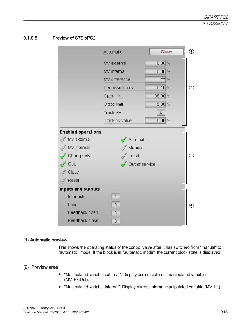
9.1.8.5 Preview of S7SipPS2
(1) Automatic previewThis shows the operating status of the control valve after it has switched from "manual" to "automatic" mode. If the block is in "automatic mode", the current block state is displayed.
(2) Preview area● "Manipulated variable external": Display current external manipulated variable
(MV_ExtOut).
● "Manipulated variable internal": Display current internal manipulated variable (MV_Int).
SIPART PS29.1 S7SipPS2
SITRANS Library for S7-300Function Manual, 02/2018, A5E35351982-02 315

● "Manipulated variable difference": Current manipulated variable error (ER)
● "Permissible dev.": permitted ± deviation (PosDeadBand) of output manipulated variable. If the manipulated variable feedback Rbk is within this range, the manipulated variable is considered reached.
● "Limit Open": Limit (PosDiOpen) for forming the "Control valve Open" signal (FbkOpenOut). If the position feedback reaches this limit, the control valve is open.
● "Limit Closed": Limit (PosDiClose) for forming the "Control valve Closed" signal (FbkCloseOut). If the position feedback reaches this limit, the control valve is closed.
● “Track manipulated variable”: (MV_TrkOn = 1) Manipulated variable is corrected to the tracking value. Tracking value for the effective manipulated variable for "Track manipulated variable"With MV_TrkRbk = 1, Rbk is displayed here, with MV_TrkRbk = 0, MV_Trk is displayed.
● "Channel MV": Display of manipulated variable from output channel block
● "Auxiliary valve monitoring": Display of current monitoring time of the auxiliary valve.
● "Valve monitoring": Display of current monitoring time of the valve.
(3) Enabled operationsThis area shows all operations for which special operator authorizations are assigned. They depend on the configuration in the engineering system (ES) that applies to this block.
Symbols for enabled operations:
● Green check mark: The OS operator can control this parameter
● Gray check mark: the OS operator cannot control this parameter at this time due to the process
● Red cross: The OS operator is generally prohibited from accessing this parameter due to the configured AS operator control permissions (OS_Perm or OS1Perm).
The following enabled operationss are shown here:
● "Manipulated variable external": You can enable external manipulated variable specification
● "Manipulated variable internal": You can enable internal manipulated variable specification
● "Change MV": You can change the manipulated variable
● "Open": You can open the valve. The display always relates to the auxiliary valve and control valve. Neither the auxiliary valve nor the control valve can be opened if there is no enable.
For the control valve this means: If a new manipulated variable is greater than the current valve position, this new manipulated variable take effect.
If text is configured for this command, it is also displayed in brackets. You can find additional information on this in the "Labeling buttons and texts" section in the APL Online Help.
● "Close": You can close the valve. The display always relates to the auxiliary valve and control valve. Neither the auxiliary valve nor the control valve can be closed if there is no enable.
SIPART PS29.1 S7SipPS2
SITRANS Library for S7-300316 Function Manual, 02/2018, A5E35351982-02
For the control valve this means: If a new manipulated variable is less than the current valve position, this new manipulated variable does not take effect and the control valve retains its position.
If text is configured for this command, it is also displayed in brackets. You can find additional information on this in the "Labeling buttons and texts" section in the APL Online Help.
● "Reset": You can reset the valve if interlocks or errors occur.
● "Automatic": You can switch to "automatic mode".
● "Manual": You can switch to "manual mode".
● "Local": You can switch to "local mode".
● "Out of service": You can switch to "Out of service" mode.
(4) Inputs and outputsThis area shows the most important parameters for this block with the current selection.
● "Interlock":This display is only visible when the corresponding block input is connected.
– 0 = Interlocking without reset is active; you can operate the block without reset once the interlocking condition has disappeared
– 1 = "Good" state
● "Local": 1 = "Local mode" is enabled
Since, depending on the configuration, the block itself forms the digital feedback signals internally via the "Open" and "Closed" positions, the following reaction results from the "Feedback open" and "Feedback closed" signals.
● Control valve:
– "Feedback open": The display is derived from the FbkOpenOut output. However, this output is formed from the configured limit for the "Open" position.
– "Feedback close": The display is derived from the FbkCloseOut output. However, this output is formed from the configured limit for the "Closed" position.
● "Control auxiliary valve": only visible when there is a auxiliary valve
– Control binary control Ctrl.Out
– "Feedback Open auxiliary valve": FbkAuxVOpenOut.
– "Feedback Closed auxiliary valve": FbkAuxCloseOut.
– “Control channel auxiliary valve": Signal for control of the auxiliary valve from the output channel block
9.1.8.6 S7SipPS2 block iconA variety of block icons is available with the following functions:
● Alarm violation. Warning and tolerance limits as well as the control system fault CSF
● Operating modes
SIPART PS29.1 S7SipPS2
SITRANS Library for S7-300Function Manual, 02/2018, A5E35351982-02 317

● Forcing states
● Interlocks
● Valve status display
● Display of feedback value (white, with decimal places)
● Operation of the manipulated variable
● Process tag type
● External/internal manipulated variable specification
The block icons from template @TemplateAPL_SITRANS.PDL:
Icons Selection of the block icon in CFC Special features1 -
Additional information on the block icon and the control options in the block icon is available in the following chapters:
● "Configuring the block icons" in the APL Online Help
● "Block icon structure" in the APL Online Help
● "Operation via the block icon" in the APL Online Help
Valve status displayThe following valve states are shown here:
Icon MeaningValve open
Valve closed
Error at valve
Valve is opening
Valve is closing
Valve stopped
SIPART PS29.1 S7SipPS2
SITRANS Library for S7-300318 Function Manual, 02/2018, A5E35351982-02

SITRANS LR HART 1010.1 S7SiLRHA
10.1.1 Description of S7SiLRHA
Object name (type + number) and family Type + number: FB 2638
Family: Sitrans
Application area of SitrLRHA The block is used for the following applications:
● Interface block between the HART driver blocks of the Sitrans LR 200, Sitrans LR 250, Sitrans LR 260 and Sitrans LR 560 modules (referred to below as Sitrans LR) for the user program and for visualization
How it works The SitrLRHA block prepares the process data received from driver blocks from a Sitrans LR and makes the data available for further use in the user program and for visualization. Data entered in the faceplate or via the block inputs is transferred to the Sitrans LR by means of driver blocks.
The function block supports all PDM configurations of the up to four HART auxiliary variables of the Sitrans LR.
NOTEIn the following, block parameters are identified e.g. by PV/SV/TV/QV_OpScaleH, PV/SV/TV/QV_OpScaleL where the PV_OpScaleH/L, SV_OpScaleH/L, TV_OpScaleH/L and QV_OpScaleH/L inputs are meant for the HART variables PV, SV, TV and QV.
Configuration Use the CFC editor to install the block in a cyclic interrupt OB (OB30 to OB38). The block is also installed automatically in the startup OB (OB 100). Moreover, to connect the I/O signals, it is imperative to call the Pcs7AnIn driver blocks (cyclic data, 4 to 20 mA), FbAnIn (HART variables) and PiDr64 (acyclic data) in the same interrupt OB and startup OB (OB100) before the SitrLRHA block in each case. The AcyclData output structure of the PiDr64 block is interconnected to the input with the same name of the SitrLRHA block.
SITRANS Library for S7-300Function Manual, 02/2018, A5E35351982-02 319
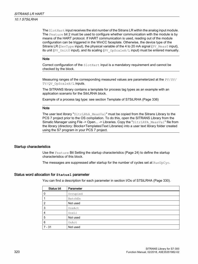
The SlotHart input receives the slot number of the Sitrans LR within the analog input module. The Feature bit 2 must be used to configure whether communication with the module is by means of the HART protocol. If HART communication is used, reading out of the module configuration can be triggered in the WinCC faceplate. Otherwise, the device type of the Sitrans LR (DevType input), the physical variable of the 4 to 20 mA signal (PV_Meas0 input), its unit (PV_Unit0 input), and its scaling (PV_OpScaleH/L input) must be entered manually.
Note
Correct configuration of the SlotHart input is a mandatory requirement and cannot be checked by the block.
Measuring ranges of the corresponding measured values are parameterized at the PV/SV/TV/QV_OpScaleH/L inputs.
The SITRANS library contains a template for process tag types as an example with an application scenario for the SitrLRHA block.
Example of a process tag type: see section Template of S7SiLRHA (Page 336)
Note
The user text library "SitrLRhA_MeasVal" must be copied from the Sitrans Library to the PCS 7 project prior to the OS compilation. To do this, open the SITRANS Library from the Simatic Manager using File -> Open... -> Libraries. Copy the "SitrLRPA_MeasVal" file from the library (directory: Blocks+Templates\Text Libraries) into a user text library folder created using the S7 program in your PCS 7 project.
Startup characteristics Use the Feature Bit Setting the startup characteristics (Page 24) to define the startup characteristics of this block.
The messages are suppressed after startup for the number of cycles set at RunUpCyc.
Status word allocation for Status1 parameter You can find a description for each parameter in section I/Os of S7SiLRHA (Page 330).
Status bit Parameter0 Occupied1 BatchEn2 Not used3 OosAct4 OosLi5 Not used6 OnAct7 - 31 Not used
SITRANS LR HART10.1 S7SiLRHA
SITRANS Library for S7-300320 Function Manual, 02/2018, A5E35351982-02
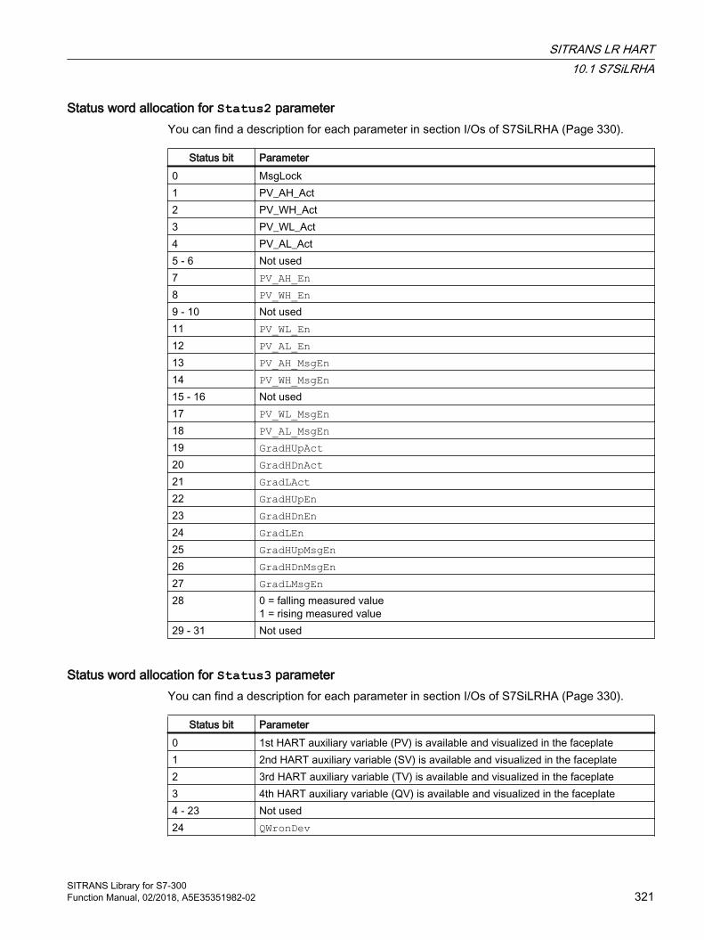
Status word allocation for Status2 parameterYou can find a description for each parameter in section I/Os of S7SiLRHA (Page 330).
Status bit Parameter0 MsgLock1 PV_AH_Act2 PV_WH_Act3 PV_WL_Act4 PV_AL_Act5 - 6 Not used7 PV_AH_En8 PV_WH_En9 - 10 Not used11 PV_WL_En12 PV_AL_En13 PV_AH_MsgEn14 PV_WH_MsgEn15 - 16 Not used17 PV_WL_MsgEn18 PV_AL_MsgEn19 GradHUpAct20 GradHDnAct21 GradLAct22 GradHUpEn23 GradHDnEn24 GradLEn25 GradHUpMsgEn26 GradHDnMsgEn27 GradLMsgEn28 0 = falling measured value
1 = rising measured value29 - 31 Not used
Status word allocation for Status3 parameterYou can find a description for each parameter in section I/Os of S7SiLRHA (Page 330).
Status bit Parameter0 1st HART auxiliary variable (PV) is available and visualized in the faceplate1 2nd HART auxiliary variable (SV) is available and visualized in the faceplate2 3rd HART auxiliary variable (TV) is available and visualized in the faceplate3 4th HART auxiliary variable (QV) is available and visualized in the faceplate4 - 23 Not used24 QWronDev
SITRANS LR HART10.1 S7SiLRHA
SITRANS Library for S7-300Function Manual, 02/2018, A5E35351982-02 321
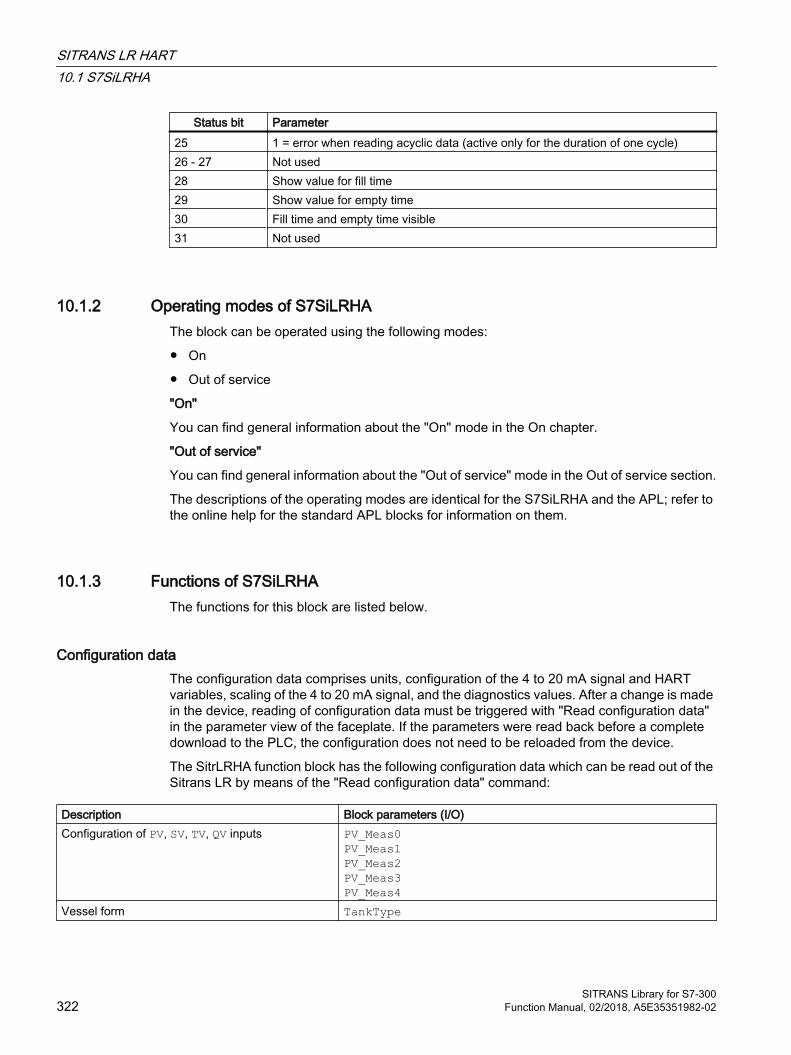
Status bit Parameter25 1 = error when reading acyclic data (active only for the duration of one cycle)26 - 27 Not used28 Show value for fill time29 Show value for empty time30 Fill time and empty time visible31 Not used
10.1.2 Operating modes of S7SiLRHAThe block can be operated using the following modes:
● On
● Out of service
"On"
You can find general information about the "On" mode in the On chapter.
"Out of service"
You can find general information about the "Out of service" mode in the Out of service section.
The descriptions of the operating modes are identical for the S7SiLRHA and the APL; refer to the online help for the standard APL blocks for information on them.
10.1.3 Functions of S7SiLRHAThe functions for this block are listed below.
Configuration data The configuration data comprises units, configuration of the 4 to 20 mA signal and HART variables, scaling of the 4 to 20 mA signal, and the diagnostics values. After a change is made in the device, reading of configuration data must be triggered with "Read configuration data" in the parameter view of the faceplate. If the parameters were read back before a complete download to the PLC, the configuration does not need to be reloaded from the device.
The SitrLRHA function block has the following configuration data which can be read out of the Sitrans LR by means of the "Read configuration data" command:
Description Block parameters (I/O)Configuration of PV, SV, TV, QV inputs PV_Meas0
PV_Meas1PV_Meas2PV_Meas3PV_Meas4
Vessel form TankType
SITRANS LR HART10.1 S7SiLRHA
SITRANS Library for S7-300322 Function Manual, 02/2018, A5E35351982-02
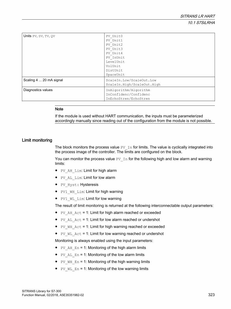
Units PV, SV, TV, QV PV_Unit0PV_Unit1PV_Unit2PV_Unit3PV_Unit4PV_InUnitLevelUnitVolUnitDistUnitSpaceUnit
Scaling 4 ... 20 mA signal ScaleIn.Low/ScaleOut.LowScaleIn.High/ScaleOut.High
Diagnostics values InAlgorithm/AlgorithmInConfidenc/ConfidencInEchoStren/EchoStren
Note
If the module is used without HART communication, the inputs must be parameterized accordingly manually since reading out of the configuration from the module is not possible.
Limit monitoringThe block monitors the process value PV_In for limits. The value is cyclically integrated into the process image of the controller. The limits are configured on the block.
You can monitor the process value PV_In for the following high and low alarm and warning limits:
● PV_AH_Lim: Limit for high alarm
● PV_AL_Lim: Limit for low alarm
● PV_Hyst: Hysteresis
● PV1_WH_Lim: Limit for high warning
● PV1_WL_Lim: Limit for low warning
The result of limit monitoring is returned at the following interconnectable output parameters:
● PV_AH_Act = 1: Limit for high alarm reached or exceeded
● PV_AL_Act = 1: Limit for low alarm reached or undershot
● PV_WH_Act = 1: Limit for high warning reached or exceeded
● PV_WL_Act = 1: Limit for low warning reached or undershot
Monitoring is always enabled using the input parameters:
● PV_AH_En = 1: Monitoring of the high alarm limits
● PV_AL_En = 1: Monitoring of the low alarm limits
● PV_WH_En = 1: Monitoring of the high warning limits
● PV_WL_En = 1: Monitoring of the low warning limits
SITRANS LR HART10.1 S7SiLRHA
SITRANS Library for S7-300Function Manual, 02/2018, A5E35351982-02 323
The corresponding message is suppressed using the parameters:
● PV_AH_MsgEn = 0: Alarm (high) messages are suppressed
● PV_AL_MsgEn = 0: Alarm (low) messages are suppressed
● PV_WH_MsgEn = 0: Warning (high) messages are suppressed
● PV_WL_MsgEn = 0: Warning (low) messages are suppressed
You can define a hysteresis (PV_Hyst) for the limits, for example to suppress signal flatter. You can also modify the limits and hysteresis via the faceplate.
Gradient monitoringThe gradient PV_Grad0 is calculated by means of a delay function configurable using LagTime. During calculation of the gradient, jumps in the input value PV_In are smoothed.
The peak values of the gradient are output in the output parameters PV_GradNP0 (negative gradient) and PV_GradPP0 (positive gradient). These are reset when the operator enters the corresponding command for resetting.
The slope of the gradient PV_Grad0 can be monitored for the following limits:
● Limit (high) for the positive gradient (GradHUpLim)
● Limit (high) for the negative gradient (GradHDnLim)
● Limit (low) for the absolute gradient (GradLLim)
Activation of the individual monitoring functions is carried out at the corresponding "Enable" parameters, e.g. GradHUpEn for activating the high gradient limit for positive gradients (GradHUpLim).
Reaching or violation of your defined limits is indicated at the corresponding "Active" output parameters, e.g. by means of GradHUpAct = 1 for the limit (high) for the positive gradient.
Messages can be output for these alarms. You can activate these as follows:
● Message for alarms (high) for the positive gradient: GradHUpMsgEn = 1
● Message for alarms (high) for the negative gradient: GradHDnMsgEn = 1
● Message for alarms (low) for the absolute gradient: GradLMsgEn = 1
Suppressing messages using the MsgLock parameterThis block provides the standard "Suppressing messages using the MsgLock parameter" function that is described in the APL Online Help.
Selecting a unit of measureThis block provides the standard function Selecting a unit of measure. The units for the 4 to 20 mA signal and the HART variables are configured on the device of the Sitrans LR via PDM and read by an operator action in the "Parameters" faceplate view with "Read configuration" or configured by the user himself if HART communication does not exist.
SITRANS LR HART10.1 S7SiLRHA
SITRANS Library for S7-300324 Function Manual, 02/2018, A5E35351982-02
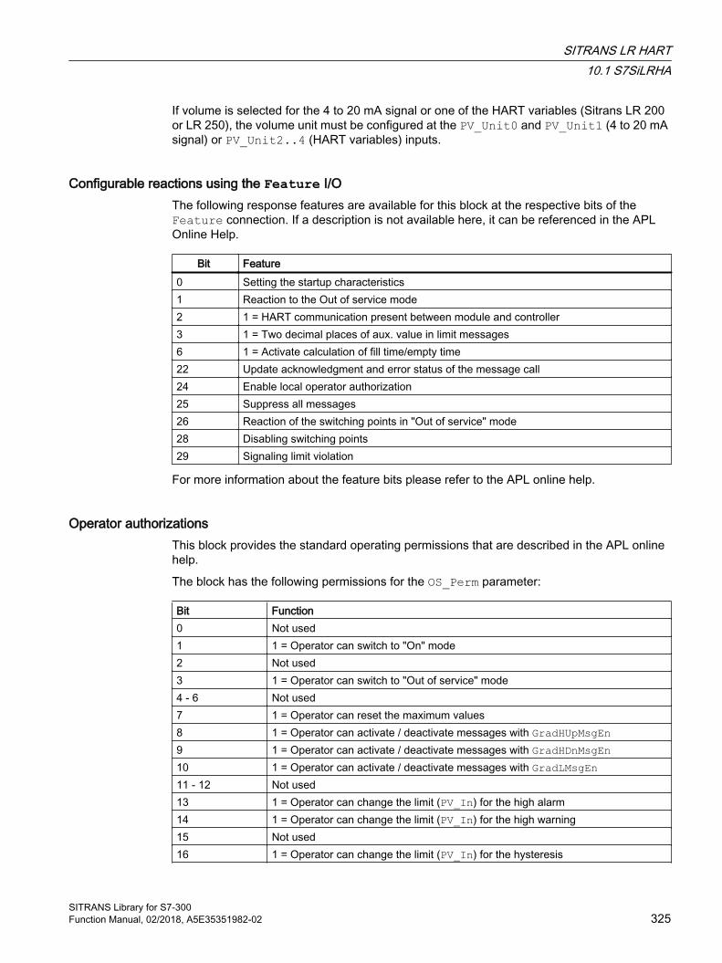
If volume is selected for the 4 to 20 mA signal or one of the HART variables (Sitrans LR 200 or LR 250), the volume unit must be configured at the PV_Unit0 and PV_Unit1 (4 to 20 mA signal) or PV_Unit2..4 (HART variables) inputs.
Configurable reactions using the Feature I/OThe following response features are available for this block at the respective bits of the Feature connection. If a description is not available here, it can be referenced in the APL Online Help.
Bit Feature0 Setting the startup characteristics1 Reaction to the Out of service mode2 1 = HART communication present between module and controller3 1 = Two decimal places of aux. value in limit messages6 1 = Activate calculation of fill time/empty time22 Update acknowledgment and error status of the message call24 Enable local operator authorization25 Suppress all messages26 Reaction of the switching points in "Out of service" mode28 Disabling switching points29 Signaling limit violation
For more information about the feature bits please refer to the APL online help.
Operator authorizationsThis block provides the standard operating permissions that are described in the APL online help.
The block has the following permissions for the OS_Perm parameter:
Bit Function0 Not used1 1 = Operator can switch to "On" mode2 Not used3 1 = Operator can switch to "Out of service" mode4 - 6 Not used7 1 = Operator can reset the maximum values8 1 = Operator can activate / deactivate messages with GradHUpMsgEn9 1 = Operator can activate / deactivate messages with GradHDnMsgEn10 1 = Operator can activate / deactivate messages with GradLMsgEn11 - 12 Not used13 1 = Operator can change the limit (PV_In) for the high alarm14 1 = Operator can change the limit (PV_In) for the high warning15 Not used16 1 = Operator can change the limit (PV_In) for the hysteresis
SITRANS LR HART10.1 S7SiLRHA
SITRANS Library for S7-300Function Manual, 02/2018, A5E35351982-02 325

17 1 = Operator can change the limit (PV_In) for the low alarm18 1 = Operator can change the limit (PV_In) for the low warning19 Not used20 1 = Operator can change the value for the high gradient limit for positive gradients
(GradHUpLim)21 1 = Operator can change the value for the high gradient limit for negative gradients
(GradHDnLim)22 1 = Operator can change the value for the low gradient limit for positive and negative
gradients (GradLLim)23 Not used24 1 = Operator can activate / deactivate messages with PV_AH_MsgEn25 1 = Operator can activate / deactivate messages with PV_WH_MsgEn26 1 = Operator can activate / deactivate messages with PV_WL_MsgEn27 1 = Operator can activate / deactivate messages with PV_AL_MsgEn28 - 31 Not used
The block has the following permissions for the OS1Perm parameter:
Bit Function0 - 13 Not used14 1 = Operator can read the diagnostics values from the device15 1 = Operator can read the configuration data from the device16 1 = Operator can write the configuration data from the device17 - 31 Not used
Simulating signalsSimulation is triggered during runtime in the faceplate's parameter view by clicking on the "Simulation" button.
You can simulate the following values in the faceplate via an input:
The 4 to 20 mA signal (PV_Out0) in the standard view is specified via the input (SimPV0).
The HART variables (PV_Out1..4) are specified in the standard view via the inputs (SimPV1..4).
You can simulate the following values via an interconnection in the CFC:
● The level (SimLevLi, Level)
● The volume (SimVolLi, Volume)
● The distance (SimDisLi, Distance)
● The space (SimSpaLi, Space)
The Level, Volume, Distance and Space outputs are simulated in accordance with the module configuration when simulation is carried out via the faceplate. The simulation value of the 4 to 20 mA signal has a higher priority than the value of the first HART auxiliary variable PV.
SITRANS LR HART10.1 S7SiLRHA
SITRANS Library for S7-300326 Function Manual, 02/2018, A5E35351982-02
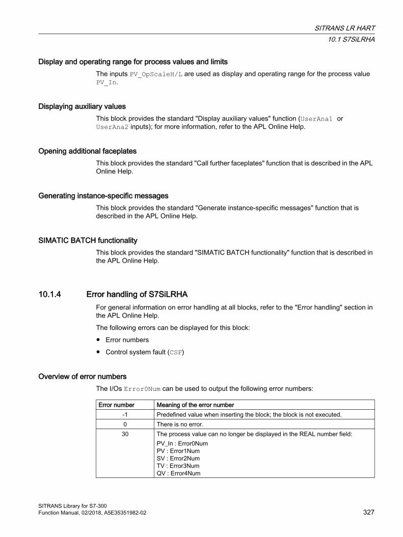
Display and operating range for process values and limitsThe inputs PV_OpScaleH/L are used as display and operating range for the process value PV_In.
Displaying auxiliary valuesThis block provides the standard "Display auxiliary values" function (UserAna1 or UserAna2 inputs); for more information, refer to the APL Online Help.
Opening additional faceplatesThis block provides the standard "Call further faceplates" function that is described in the APL Online Help.
Generating instance-specific messagesThis block provides the standard "Generate instance-specific messages" function that is described in the APL Online Help.
SIMATIC BATCH functionalityThis block provides the standard "SIMATIC BATCH functionality" function that is described in the APL Online Help.
10.1.4 Error handling of S7SiLRHAFor general information on error handling at all blocks, refer to the "Error handling" section in the APL Online Help.
The following errors can be displayed for this block:
● Error numbers
● Control system fault (CSF)
Overview of error numbersThe I/Os Error0Num can be used to output the following error numbers:
Error number Meaning of the error number-1 Predefined value when inserting the block; the block is not executed.0 There is no error.30 The process value can no longer be displayed in the REAL number field:
PV_In : Error0NumPV : Error1NumSV : Error2NumTV : Error3NumQV : Error4Num
SITRANS LR HART10.1 S7SiLRHA
SITRANS Library for S7-300Function Manual, 02/2018, A5E35351982-02 327
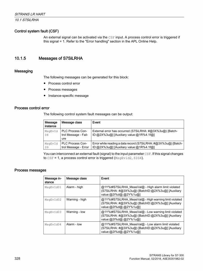
Control system fault (CSF)An external signal can be activated via the CSF input. A process control error is triggered if this signal = 1. Refer to the "Error handling" section in the APL Online Help.
10.1.5 Messages of S7SiLRHA
Messaging The following messages can be generated for this block:
● Process control error
● Process messages
● Instance-specific message
Process control error The following control system fault messages can be output:
Message instance
Message class Event
MsgEvId08
PLC Process Con‐trol Message - Fail‐ure
External error has occurred (S7SiLRHA: #@3X%3u@) [Batch‐ID:@2X%3u@] [Auxiliary value:@1R%4.1f@]
MsgEvId09
PLC Process Con‐trol Message - Error
Error while reading a data record (S7SiLRHA: #@3X%3u@) [Batch‐ID:@2X%3u@] [Auxiliary value:@1R%4.1f@]
You can interconnect an external fault (signal) to the input parameter CSF. If this signal changes to CSF = 1, a process control error is triggered (MsgEvld2, SIG4).
Process messages
Message in‐stance
Message class Event
MsgEvId01 Alarm - high @1Y%t#S7SiLRHA_MeasVal@ - High alarm limit violated (S7SiLRHA: #@3X%3u@) [BatchID:@2X%3u@] [Auxiliary value:@2I%d@.@2Y%1u@]
MsgEvId02 Warning - high @1Y%t#S7SiLRHA_MeasVal@ - High warning limit violated (S7SiLRHA: #@3X%3u@) [BatchID:@2X%3u@] [Auxiliary value:@2I%d@.@2Y%1u@]
MsgEvId03 Warning - low @1Y%t#S7SiLRHA_MeasVal@ - Low warning limit violated (S7SiLRHA: #@3X%3u@) [BatchID:@2X%3u@] [Auxiliary value:@2I%d@.@2Y%1u@]
MsgEvId04 Alarm - low @1Y%t#S7SiLRHA_MeasVal@ - Low alarm limit violated (S7SiLRHA: #@3X%3u@) [BatchID:@2X%3u@] [Auxiliary value:@2I%d@.@2Y%1u@]
SITRANS LR HART10.1 S7SiLRHA
SITRANS Library for S7-300328 Function Manual, 02/2018, A5E35351982-02
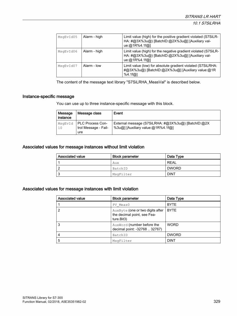
MsgEvId05 Alarm - high Limit value (high) for the positive gradient violated (S7SiLR‐HA: #@3X%3u@) [BatchID:@2X%3u@] [Auxiliary val‐ue:@1R%4.1f@]
MsgEvId06 Alarm - high Limit value (high) for the negative gradient violated (S7SiLR‐HA: #@3X%3u@) [BatchID:@2X%3u@] [Auxiliary val‐ue:@1R%4.1f@]
MsgEvId07 Alarm - low Limit value (low) for absolute gradient violated (S7SiLRHA: #@3X%3u@) [BatchID:@2X%3u@] [Auxiliary value:@1R%4.1f@]
The content of the message text library "S7SiLRHA_MeasVal" is described below.
Instance-specific message You can use up to three instance-specific message with this block.
Message instance
Message class Event
MsgEvId10
PLC Process Con‐trol Message - Fail‐ure
External message (S7SiLRHA: #@3X%3u@) [BatchID:@2X%3u@] [Auxiliary value:@1R%4.1f@]
Associated values for message instances without limit violation
Associated value Block parameter Data Type1 Aux REAL2 BatchID DWORD3 MsgFilter DINT
Associated values for message instances with limit violation
Associated value Block parameter Data Type1 PV_Meas0 BYTE2 AuxByte (one or two digits after
the decimal point, see Fea‐ture.Bit3)
BYTE
3 AuxWord (number before the decimal point: -32768 .. 32767)
WORD
4 BatchID DWORD5 MsgFilter DINT
SITRANS LR HART10.1 S7SiLRHA
SITRANS Library for S7-300Function Manual, 02/2018, A5E35351982-02 329

Message texts and their text numbers The following table shows the message texts and their numbers in the text library "S7SiLRHA_MeasVal" for the S7SiLRHA block (FB 2638):
Text number
Message text
0 <Invalid value>1 Volume2 Level3 Distance4 Space
10.1.6 I/Os of S7SiLRHA
Input parameters
Parameter Description Type DefaultSlotHart Slot number of the Sitrans LR within the AI module in
the ET 200M from HW ConfigINT 0
DevType Device type of Sitrans LR1: Sitrans LR 2002: Sitrans LR 2503: Sitrans LR 2604: Sitrans LR 560
INT 0
PV_In Process value (4 to 20 mA signal) REAL 0.0QCPV_In Quality Code of Process Value (4..20mA signal) BYTE 16#80PV First HART variable (primary variable) REAL 0.0QCPV Quality Code of first HART variable (Primary variable) BYTE 16#FFSV Second HART variable (secondary variable) REAL 0.0QCSV Quality Code of second HART variable (Secondary
variable)BYTE 16#FF
TV Third HART variable (tertiary variable) REAL 0.0QCTV Quality Code of third HART variable (Tertiary variable) BYTE 16#FFQV Fourth HART variable (quaternary variable) REAL 0.0QCQV Quality Code of fourth HART variable (Quatenary var‐
iable)BYTE 16#FF
InPV_AH_Lim Limit sensor PV_In:Alarm limit (high)
REAL 0.0
InPV_WH_Lim Limit sensor PV_In:Warning limit (high)
REAL 0.0
InPV_Hyst Limit sensor PV_In:Hysteresis for alarm and warning limits
REAL 0.0
SITRANS LR HART10.1 S7SiLRHA
SITRANS Library for S7-300330 Function Manual, 02/2018, A5E35351982-02
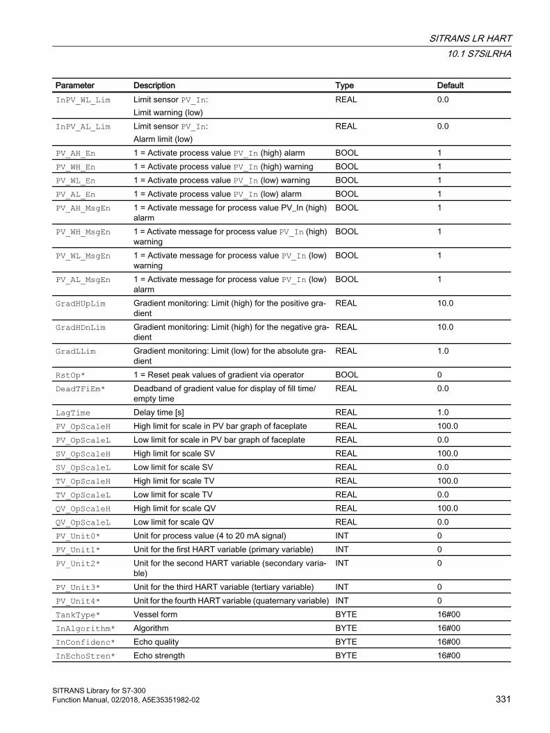
Parameter Description Type DefaultInPV_WL_Lim Limit sensor PV_In:
Limit warning (low)REAL 0.0
InPV_AL_Lim Limit sensor PV_In:Alarm limit (low)
REAL 0.0
PV_AH_En 1 = Activate process value PV_In (high) alarm BOOL 1PV_WH_En 1 = Activate process value PV_In (high) warning BOOL 1PV_WL_En 1 = Activate process value PV_In (low) warning BOOL 1PV_AL_En 1 = Activate process value PV_In (low) alarm BOOL 1PV_AH_MsgEn 1 = Activate message for process value PV_In (high)
alarmBOOL 1
PV_WH_MsgEn 1 = Activate message for process value PV_In (high) warning
BOOL 1
PV_WL_MsgEn 1 = Activate message for process value PV_In (low) warning
BOOL 1
PV_AL_MsgEn 1 = Activate message for process value PV_In (low) alarm
BOOL 1
GradHUpLim Gradient monitoring: Limit (high) for the positive gra‐dient
REAL 10.0
GradHDnLim Gradient monitoring: Limit (high) for the negative gra‐dient
REAL 10.0
GradLLim Gradient monitoring: Limit (low) for the absolute gra‐dient
REAL 1.0
RstOp* 1 = Reset peak values of gradient via operator BOOL 0DeadTFiEm* Deadband of gradient value for display of fill time/
empty timeREAL 0.0
LagTime Delay time [s] REAL 1.0PV_OpScaleH High limit for scale in PV bar graph of faceplate REAL 100.0PV_OpScaleL Low limit for scale in PV bar graph of faceplate REAL 0.0SV_OpScaleH High limit for scale SV REAL 100.0SV_OpScaleL Low limit for scale SV REAL 0.0TV_OpScaleH High limit for scale TV REAL 100.0TV_OpScaleL Low limit for scale TV REAL 0.0QV_OpScaleH High limit for scale QV REAL 100.0QV_OpScaleL Low limit for scale QV REAL 0.0PV_Unit0* Unit for process value (4 to 20 mA signal) INT 0PV_Unit1* Unit for the first HART variable (primary variable) INT 0PV_Unit2* Unit for the second HART variable (secondary varia‐
ble)INT 0
PV_Unit3* Unit for the third HART variable (tertiary variable) INT 0PV_Unit4* Unit for the fourth HART variable (quaternary variable) INT 0TankType* Vessel form BYTE 16#00InAlgorithm* Algorithm BYTE 16#00InConfidenc* Echo quality BYTE 16#00InEchoStren* Echo strength BYTE 16#00
SITRANS LR HART10.1 S7SiLRHA
SITRANS Library for S7-300Function Manual, 02/2018, A5E35351982-02 331

Parameter Description Type DefaultGradHUpEn 1 = Enable gradient monitoring (high) for positive
changesBOOL 1
GradHDnEn 1 = Enable gradient monitoring (high) for negative changes
BOOL 1
GradLEn 1 = Enable gradient monitoring (low) BOOL 0OnOp* 1 = "On" mode via operator BOOL 0OosOp* 1 = "Out of service", via OS operator BOOL 0OosLi 1 = "Out of service", via interconnection or SFC (0-1
edge transition)BOOL 0
GradHUpMsgEn 1 = Enable gradient (high) message for positive changes
BOOL 1
GradHDnMsgEn 1 = Enable gradient (high) message for negative changes
BOOL 1
GradLMsgEn 1 = Enable gradient (high) message for negative changes
BOOL 1
TimeFactor Time unit:0 = seconds1 = minutes2 = hours
INT 0
MsgLock 1 = Suppress process messages. BOOL 0SampleTime Sampling time [s] (assigned automatically) REAL 0.1RunUpCyc Number of cycles in startup; messages are sup‐
pressed during these cyclesINT 3
MsgEvId01..10 Message number (assigned automatically) DWORD 16#00000000BatchEn 1 = Enable allocation BOOL 0BatchID Batch ID DWORD 16#00000000BatchName Batch name S7-String StepNo Batch step number DWORD 16#00000000Occupied 1 = Occupied by batch control BOOL 0CSF 1 = External error (control system fault) BOOL 0ExtMsg Binary input for freely selectable message BOOL 0UserStatus Freely assignable bits for use in PCS 7 OS BYTE 16#00OS_Perm I/O for operating permissions STRUCT
● Bit 0 : BOOL…● Bit31: BOOL
-● 1…● 1
OS1Perm I/O for operating permissions STRUCT● Bit 0 : BOOL…● Bit31: BOOL
-● 1…● 1
OpSt_In Input parameter for local operator authorization, to be interconnected with the Out output parameter of the upstream OpStations block
DWORD 16#00000000
SITRANS LR HART10.1 S7SiLRHA
SITRANS Library for S7-300332 Function Manual, 02/2018, A5E35351982-02
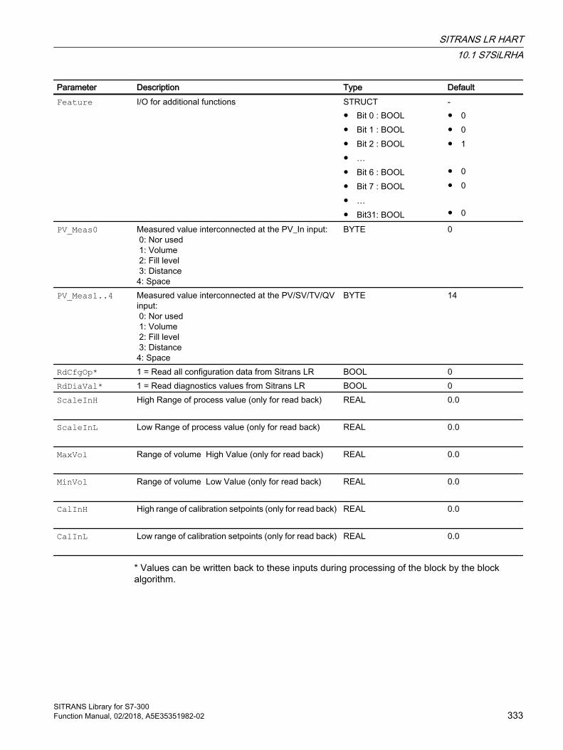
Parameter Description Type DefaultFeature I/O for additional functions STRUCT
● Bit 0 : BOOL● Bit 1 : BOOL● Bit 2 : BOOL● …● Bit 6 : BOOL● Bit 7 : BOOL● …● Bit31: BOOL
-● 0● 0● 1 ● 0● 0 ● 0
PV_Meas0 Measured value interconnected at the PV_In input: 0: Nor used 1: Volume 2: Fill level 3: Distance4: Space
BYTE 0
PV_Meas1..4 Measured value interconnected at the PV/SV/TV/QV input: 0: Nor used 1: Volume 2: Fill level 3: Distance4: Space
BYTE 14
RdCfgOp* 1 = Read all configuration data from Sitrans LR BOOL 0RdDiaVal* 1 = Read diagnostics values from Sitrans LR BOOL 0ScaleInH High Range of process value (only for read back) REAL
0.0
ScaleInL Low Range of process value (only for read back) REAL
0.0
MaxVol Range of volume High Value (only for read back) REAL
0.0
MinVol Range of volume Low Value (only for read back) REAL
0.0
CalInH High range of calibration setpoints (only for read back) REAL
0.0
CalInL Low range of calibration setpoints (only for read back) REAL
0.0
* Values can be written back to these inputs during processing of the block by the block algorithm.
SITRANS LR HART10.1 S7SiLRHA
SITRANS Library for S7-300Function Manual, 02/2018, A5E35351982-02 333

In/out parameters
Parameter Description Type DefaultAcyclData Acyclic data from driver block PiDr64 (intercon‐
nect this input with output AcyclData of PiDr64)
STRUCT● SlotRd : INT● …● RetValWr: WORD● Input : STRUCT● Output : STRUCT● NewDiag : INT● DiagData : STRUCT
Output parameters
Parameter Description Type DefaultQWronDev 1 = Wrong device connected BOOL 1PV_Out0 Process value output (4 to 20 mA signal) REAL 0.0PV_Out1 Output first HART variable (primary variable) REAL 0.0PV_Out2 Output second HART variable (secondary varia‐
ble)REAL 0.0
PV_Out3 Output third HART variable (tertiary variable) REAL 0.0PV_Out4 Output fourth HART variable (quaternary variable) REAL 0.0TankFilled Output process value PV in [%] REAL 0.0TimeFillS Fill time calculated with current gradient value [s] REAL 0.0TimeEmptyS Empty time calculated with current gradient value
[s]REAL 0.0
TimeFill Fill time calculated with current gradient value [TFillUnit]
REAL 0.0
TimeEmpty Empty time calculated with current gradient value [TEmptyUnit]
REAL 0.0
TFillUnit Unit of TimeFill INT 0TEmptyUnit Unit of TimeEmpty INT 0Algorithm Algorithm BYTE 16#00Confidenc Echo quality BYTE 16#00EchoStren Echo strength BYTE 16#00PV_Grad0 Process value gradient (4 to 20 mA signal) REAL 0.0PV_GradPP0 Gradient value, maximum peak value REAL 0.0PV_GradNP0 Gradient value, minimum peak value REAL 0.0Level Current level REAL 0.0QCLevel Quality code of current level BYTE 16#00Volume Current volume REAL 0.0QCVolume Quality code of current volume BYTE 16#00Distance Current distance REAL 0.0
SITRANS LR HART10.1 S7SiLRHA
SITRANS Library for S7-300334 Function Manual, 02/2018, A5E35351982-02
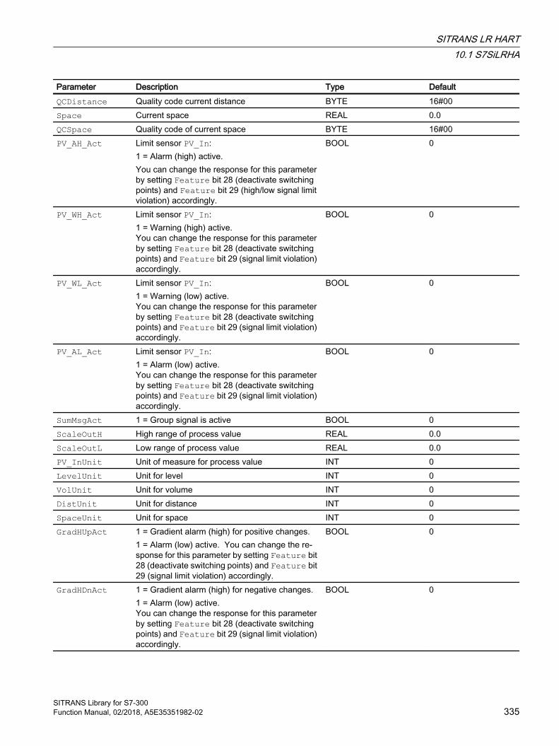
Parameter Description Type DefaultQCDistance Quality code current distance BYTE 16#00Space Current space REAL 0.0QCSpace Quality code of current space BYTE 16#00PV_AH_Act Limit sensor PV_In:
1 = Alarm (high) active. You can change the response for this parameter by setting Feature bit 28 (deactivate switching points) and Feature bit 29 (high/low signal limit violation) accordingly.
BOOL 0
PV_WH_Act Limit sensor PV_In:1 = Warning (high) active. You can change the response for this parameter by setting Feature bit 28 (deactivate switching points) and Feature bit 29 (signal limit violation) accordingly.
BOOL 0
PV_WL_Act Limit sensor PV_In:1 = Warning (low) active. You can change the response for this parameter by setting Feature bit 28 (deactivate switching points) and Feature bit 29 (signal limit violation) accordingly.
BOOL 0
PV_AL_Act Limit sensor PV_In:1 = Alarm (low) active. You can change the response for this parameter by setting Feature bit 28 (deactivate switching points) and Feature bit 29 (signal limit violation) accordingly.
BOOL 0
SumMsgAct 1 = Group signal is active BOOL 0ScaleOutH High range of process value REAL 0.0ScaleOutL Low range of process value REAL 0.0PV_InUnit Unit of measure for process value INT 0LevelUnit Unit for level INT 0VolUnit Unit for volume INT 0DistUnit Unit for distance INT 0SpaceUnit Unit for space INT 0GradHUpAct 1 = Gradient alarm (high) for positive changes.
1 = Alarm (low) active. You can change the re‐sponse for this parameter by setting Feature bit 28 (deactivate switching points) and Feature bit 29 (signal limit violation) accordingly.
BOOL 0
GradHDnAct 1 = Gradient alarm (high) for negative changes. 1 = Alarm (low) active. You can change the response for this parameter by setting Feature bit 28 (deactivate switching points) and Feature bit 29 (signal limit violation) accordingly.
BOOL 0
SITRANS LR HART10.1 S7SiLRHA
SITRANS Library for S7-300Function Manual, 02/2018, A5E35351982-02 335
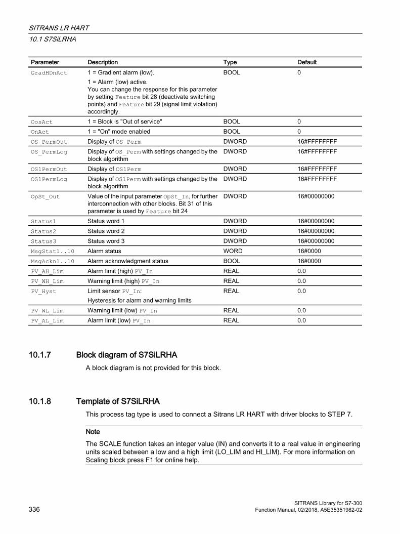
Parameter Description Type DefaultGradHDnAct 1 = Gradient alarm (low).
1 = Alarm (low) active. You can change the response for this parameter by setting Feature bit 28 (deactivate switching points) and Feature bit 29 (signal limit violation) accordingly.
BOOL 0
OosAct 1 = Block is "Out of service" BOOL 0OnAct 1 = "On" mode enabled BOOL 0OS_PermOut Display of OS_Perm DWORD 16#FFFFFFFFOS_PermLog Display of OS_Perm with settings changed by the
block algorithmDWORD 16#FFFFFFFF
OS1PermOut Display of OS1Perm DWORD 16#FFFFFFFFOS1PermLog Display of OS1Perm with settings changed by the
block algorithmDWORD 16#FFFFFFFF
OpSt_Out Value of the input parameter OpSt_In, for further interconnection with other blocks. Bit 31 of this parameter is used by Feature bit 24
DWORD 16#00000000
Status1 Status word 1 DWORD 16#00000000Status2 Status word 2 DWORD 16#00000000Status3 Status word 3 DWORD 16#00000000MsgStat1..10 Alarm status WORD 16#0000MsgAckn1..10 Alarm acknowledgment status BOOL 16#0000PV_AH_Lim Alarm limit (high) PV_In REAL 0.0PV_WH_Lim Warning limit (high) PV_In REAL 0.0PV_Hyst Limit sensor PV_In:
Hysteresis for alarm and warning limits REAL 0.0
PV_WL_Lim Warning limit (low) PV_In REAL 0.0PV_AL_Lim Alarm limit (low) PV_In REAL 0.0
10.1.7 Block diagram of S7SiLRHAA block diagram is not provided for this block.
10.1.8 Template of S7SiLRHAThis process tag type is used to connect a Sitrans LR HART with driver blocks to STEP 7.
Note
The SCALE function takes an integer value (IN) and converts it to a real value in engineering units scaled between a low and a high limit (LO_LIM and HI_LIM). For more information on Scaling block press F1 for online help.
SITRANS LR HART10.1 S7SiLRHA
SITRANS Library for S7-300336 Function Manual, 02/2018, A5E35351982-02
The Scaling block trims the value of PVin 4 to 20 mA signal.The inputs for the Hart auxiliary variables of the function block S7SiLRHA (PV, SV, TV, QV) are interconnected with the corresponding input from HW Config.The Laddr input of the PiDr64 block (AcyclicData) is configured with the address of the 4 to 20 mA signal (not interconnected!).
The SlotHart input receives the slot number of the SITRANS LR module within the analog input module at the Sitrans LR (S7SiLRHA) block. The Feature bit 2 must be used to configure whether communication with the module is by means of the HART protocol.
All required information can be found in HW Config.
Note
Correct configuration of the SlotHart input is a mandatory requirement and cannot be checked by the block.
10.1.9 Operator control & monitoring
10.1.9.1 Views of S7SiLRHA
Views of the SitrLRHA blockThe SitrLRHA block has the following views:
● Standard view of S7SiLRHA (Page 338)
● Alarm view (Page 10)
● Limit view of S7SiLRHA (Page 341)
● Trend view (Page 11)
● Parameter view of S7SiLRHA (Page 342)
● Preview of S7SiLRHA (Page 343)
● Batch view (Page 9)
For general information on the faceplate and block icon, refer to the sections "Faceplate structure" and "Block icon structure" in the APL Online Help.
SITRANS LR HART10.1 S7SiLRHA
SITRANS Library for S7-300Function Manual, 02/2018, A5E35351982-02 337
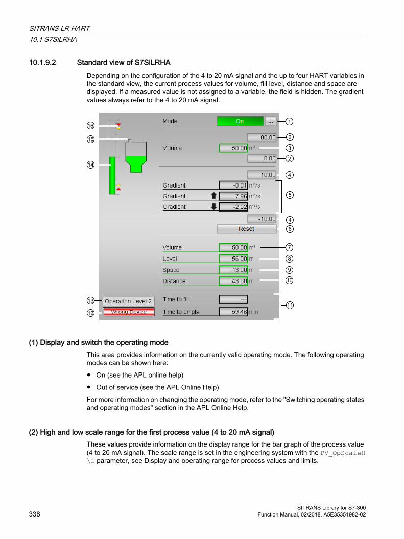
10.1.9.2 Standard view of S7SiLRHADepending on the configuration of the 4 to 20 mA signal and the up to four HART variables in the standard view, the current process values for volume, fill level, distance and space are displayed. If a measured value is not assigned to a variable, the field is hidden. The gradient values always refer to the 4 to 20 mA signal.
(1) Display and switch the operating modeThis area provides information on the currently valid operating mode. The following operating modes can be shown here:
● On (see the APL online help)
● Out of service (see the APL Online Help)
For more information on changing the operating mode, refer to the "Switching operating states and operating modes" section in the APL Online Help.
(2) High and low scale range for the first process value (4 to 20 mA signal)These values provide information on the display range for the bar graph of the process value (4 to 20 mA signal). The scale range is set in the engineering system with the PV_OpScaleH\L parameter, see Display and operating range for process values and limits.
SITRANS LR HART10.1 S7SiLRHA
SITRANS Library for S7-300338 Function Manual, 02/2018, A5E35351982-02
(3) Display of first process value (4 to 20 mA signal)This area indicates the current process value (4 to 20 mA signal). The name of the configured measured value is displayed depending on the PV_Meas0 variable, in this case "Volume".
(4) High and low scale range for the gradient valueThese values provide information on the display range for the bar graph of the gradient. The scale range corresponds to 10% of the scale range for the process value (4 to 20 mA signal): If you have entered a scale range for the process value of 0 to 100, for example, the scale range for the gradient is automatically defined as -10 to 10.
The current gradient value is displayed if one of the monitoring functions is enabled:
● Gradient monitoring for positive changes (GradHUpEn = 1)
● Gradient monitoring for negative changes (GradHDnEn = 1)
● Gradient monitoring (GradLEn = 1)
(5) Display of gradientThis area shows the current, minimum and maximum gradient values of the 4 to 20 mA signal as well as rising and falling of the value. This display of the minimum and maximum gradient value functions like a slave pointer.
The current gradient value is displayed if one of the monitoring functions is enabled:
● Gradient monitoring for positive changes (GradHUpEn = 1)
● Gradient monitoring for negative changes (GradHDnEn = 1)
● Gradient monitoring (GradLEn = 1)
The maximum peak gradient value is displayed if the gradient monitoring function for positive changes is enabled (GradHUpEn = 1)
The minimum peak gradient value is displayed if the gradient monitoring function for negative changes is enabled (GradHDnEn = 1)
(6) Resetting of peak values of the gradientUsing these buttons you can reset the maximum or minimum peak value of the gradient (output parameters PV_GradPP0 and PV_GradNP0).
The button is displayed if the gradient monitoring function for positive (GradHUpEn = 1) or negative (GradHDnEn = 1) changes is enabled.
(7), (8), (9) and (10) Display of HART variablesThis area provides information on the current process values of the HART variables. The name of the configured measured value is displayed depending on the PV_Meas1..4 variable, in this case "Volume", "Level", "Space" und "Distance".
SITRANS LR HART10.1 S7SiLRHA
SITRANS Library for S7-300Function Manual, 02/2018, A5E35351982-02 339

(11) Display of fill time and empty timeFill time and empty time are shown in this area if Feature bit 6 (Activate calculation of fill time/empty time) is enabled.
With a positive gradient value, a value is calculated for the fill time. With a negative gradient value, a value is calculated for the empty time.
The calculated times are only shown if the gradient value is outside the deadband (DeadTFiEm).
(12) Display area for block statesThis area provides additional information on the operating state of the block:
● "Wrong device"
(13) Display area for switch permissionThis area provides the text of the current OS, according to the enumeration configured at the PERMIS input.
(14) Bar graph for the first "Process value" (4 to 20 mA signal)This area shows the current first "Process value" (4 to 20 mA signal) in the form of a bar graph. The visible area in the bar graph depends on the configuration in the engineering system (ES), see Display and operating range for process values and limits.
(15) Display of type of tank and levelThis display shows you the configured type of tank. This is specified by the "TankType" value. In addition, the current level in the tank is displayed.
(16) Limit displayThese small, colored triangles indicate the specified limits of the 4 to 20 mA signal in the bar graph.
SITRANS LR HART10.1 S7SiLRHA
SITRANS Library for S7-300340 Function Manual, 02/2018, A5E35351982-02

10.1.9.3 Limit view of S7SiLRHAThe limits of the 4 to 20 mA signal and the limits for the gradient monitoring of the 4 to 20 mA signal can be specified in this view. The displayed texts depend on the configuration of the limit sensors on the block or in the module.
(1) Process value limits (4 to 20 mA signal)In this area, you can enter the limits for the 4 to 20 mA signal. You can change the following limits:
● "H alarm": High alarm
● "H warning": High warning
● "Hysteresis"
● "L warning": Low warning
● "L alarm": Low alarm
(2) Gradient limitsYou can enter gradient limits in this area. Refer to the "Changing values" section in the APL Online Help.
You can change the following limits:
● "H alarm ⇑": Gradient for the upper gradient for positive changes
● "H alarm ⇓": Gradient for the upper rate of rise for negative changes
● "L alarm ⇑⇓": Gradient for the lower rate of rise (absolute)
SITRANS LR HART10.1 S7SiLRHA
SITRANS Library for S7-300Function Manual, 02/2018, A5E35351982-02 341
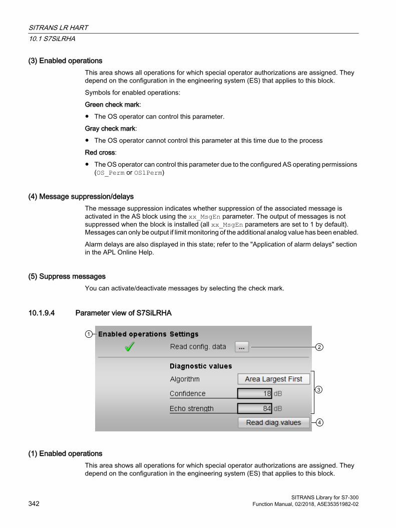
(3) Enabled operationsThis area shows all operations for which special operator authorizations are assigned. They depend on the configuration in the engineering system (ES) that applies to this block.
Symbols for enabled operations:
Green check mark:
● The OS operator can control this parameter.
Gray check mark:
● The OS operator cannot control this parameter at this time due to the process
Red cross:
● The OS operator can control this parameter due to the configured AS operating permissions (OS_Perm or OS1Perm)
(4) Message suppression/delaysThe message suppression indicates whether suppression of the associated message is activated in the AS block using the xx_MsgEn parameter. The output of messages is not suppressed when the block is installed (all xx_MsgEn parameters are set to 1 by default). Messages can only be output if limit monitoring of the additional analog value has been enabled.
Alarm delays are also displayed in this state; refer to the "Application of alarm delays" section in the APL Online Help.
(5) Suppress messagesYou can activate/deactivate messages by selecting the check mark.
10.1.9.4 Parameter view of S7SiLRHA
(1) Enabled operationsThis area shows all operations for which special operator authorizations are assigned. They depend on the configuration in the engineering system (ES) that applies to this block.
SITRANS LR HART10.1 S7SiLRHA
SITRANS Library for S7-300342 Function Manual, 02/2018, A5E35351982-02

Symbols for enabled operations:
● Green check mark: The OS operator can control this parameter
● Gray check mark: the OS operator cannot control this parameter at this time due to the process
● Red cross: The OS operator cannot control this parameter due to the configured AS operating permissions (OS_Perm or OS1Perm)
(2) Reading the configuration dataIn this area, you can read all configuration data relevant to the block from SITRANS LR.
(3) Diagnostics valuesThe diagnostics values for algorithm, echo quality and echo strength of the Sitrans LR are displayed in this area.
(4) Reading the diagnostics valuesIn this area, you can read the diagnostics values from SITRANS LR.
10.1.9.5 Preview of S7SiLRHA
(1) Process valuesThis area shows the real process values (PV_In, PV, SV, TV, QV ).
(2) Enabled operationsThis area shows all operations for which special operator authorizations are assigned. They depend on the configuration in the engineering system (ES) that applies to this block.
SITRANS LR HART10.1 S7SiLRHA
SITRANS Library for S7-300Function Manual, 02/2018, A5E35351982-02 343
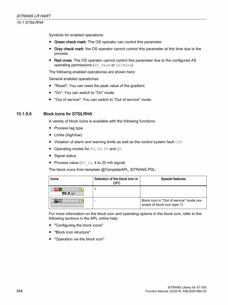
Symbols for enabled operations:
● Green check mark: The OS operator can control this parameter
● Gray check mark: the OS operator cannot control this parameter at this time due to the process
● Red cross: The OS operator cannot control this parameter due to the configured AS operating permissions (OS_Perm or OS1Perm)
The following enabled operationss are shown here:
General enabled operationss:
● "Reset": You can reset the peak value of the gradient.
● "On": You can switch to "On" mode.
● "Out of service": You can switch to "Out of service" mode.
10.1.9.6 Block icons for S7SiLRHAA variety of block icons is available with the following functions:
● Process tag type
● Limits (high/low)
● Violation of alarm and warning limits as well as the control system fault CSF● Operating modes for PV, SV, TV and QV● Signal status
● Process value (PV_In, 4 to 20 mA signal)
The block icons from template @TemplateAPL_SITRANS.PDL:
Icons Selection of the block icon in CFC
Special features
1
- Block icon in "Out of service" mode (ex‐ample of block icon type 1)
For more information on the block icon and operating options in the block icon, refer to the following sections in the APL online help:
● "Configuring the block icons"
● "Block icon structure"
● "Operation via the block icon"
SITRANS LR HART10.1 S7SiLRHA
SITRANS Library for S7-300344 Function Manual, 02/2018, A5E35351982-02
Driver blocks 1111.1 PiDr64
11.1.1 Description of PiDr64
Object name (type + number) and family Type + number: FB 2602
Family: AdvLibPI
Area of application for PiDr64 The block is used for the following applications:
● Exchange of acyclic data (data record length up to 64 bytes) with a DP slave
● Reading the diagnostics data of a DP slave
How it works The block reads/writes acyclic data of a DP slave from/to the device.
Configuration Use the CFC editor to install the block in a cyclic interrupt OB (OB30 to OB38).
When the CFC function "Generate module drivers" is used, the following occurs automatically:
● The member variables of input structure Addr (.Laddr0..6) are assigned the address parameters configured in HW Config. Input Addr.Laddr0 is assigned the diagnostics address, and the other inputs Addr.Laddr1..6 are assigned the logical address of the respective slot. The member variable is assigned the value -1 if a slot is not configured in HW Config.
● The Mode in/out parameter is interconnected to the corresponding OMode_xx output parameter of the MOD_XXXX block.
Write the first slot's address that was generated in HW Config to input parameter Laddr.
Note
If you are not using the CFC function "Generate module drivers", parameterize the addresses of input structure Addr and the Mode in/out parameter manually. The block expects the values Mode = 16#80xxxxxx for "I/O data can be read", and 16#00xxxxxx (or RackF = TRUE) for "invalid I/O data".
SITRANS Library for S7-300Function Manual, 02/2018, A5E35351982-02 345

The Addr input structure gets the following values:
Parameter AddressingLaddr Volume flow input address (AI)Addr.Laddr0 Diagnostics address of the MAG6000Addr.Laddr1 Input address slot 1 (= volume flow input address(AI))Addr.Laddr2 Input address slot 2Addr.Laddr3 Input address slot 3Addr.Laddr4/5/6 -1
Address -1 is set by default if no slot is configured.
A template for process tag types is available in the SITRANS Library as an example for the PiDr64 block:
Example of a process tag type:
● Template of Mag6T
Startup characteristics The PiDr64 block resets the totalizer for the diagnostics data (output AcyclData.NewDiag) to zero and sets an internal bit memory to zero to read the current diagnostics data in the cyclic call.
Status word allocation for Status parameter This block does not have the Status parameter.
11.1.2 Operating modes PiDr64
Operating modes PiDr64 This block does not have any operating modes.
11.1.3 Functions of PiDr64
Functions of PiDr64 The functions for this block are listed below.
Driver blocks11.1 PiDr64
SITRANS Library for S7-300346 Function Manual, 02/2018, A5E35351982-02
Reading acyclic values from the DP slaveReading of acyclic data is initiated by writing the number of the data record to be read to output AcyclData.ReqRd. The number of the slot from which the data is read must be set simultaneously at output AcyclData.SlotRd, while the data record length in bytes is set at output AcyclData.LenRd.
On completion of the read cycle (with/without error), the block copies the number of the data record that was read to output AcyclData.RdyRead. The read data is now available in output structure AcyclData.Input, while the return value of the RDREC call (SFB52) is set in output variable AcyclData.RetValRd. For information on the meaning of the return value, refer to the Online Help of the RDRECblock.
If a temporary error occurs, the block repeats the read job up to five times at delay intervals of one second before the job is closed with a temporary error. Otherwise, the block does not evaluate the return value.
Writing acyclic values to the process imageWriting of acyclic data is initiated by writing the number of the data record to be written to output AcyclData.ReqWr. The number of the slot to which the data is written must be set simultaneously at output AcyclData.SlotWr, the data record length is set at output AcyclData.LenWr , and the data to be written is set at output structure AcyclData.Output.
On completion of the write job (with/without error), the block copies the number of the data record that was written to output AcyclData.RdyWrite , and the return value of the WRREC call (SFB53) to output variable AcyclData.RetValRd. For information on the meaning of the return value, refer to the Online Help of the WRRECblock.
If a temporary error occurs, the block repeats the write job up to five times at delay intervals of one second before the job is closed with a temporary error. Otherwise, the block does not evaluate the return value.
Reading diagnostics dataIf a diagnostics interrupt (OB82) is reported for the block instance, the diagnostics data is read and copied to output structure AcyclData.DiagData . Output AcyclData.NewDiag is incremented by one to signal new diagnostics data. The length of diagnostics data is limited to 20 bytes.
Retaining last valuesSince the block only reads data on request, the data will not be changed if the connection to the DP slave is missing (Mode input <> 16#80xxxxxx or RackF = TRUE). All jobs for reading/writing acyclic data are rejected if an error is pending.
Simulating signalsThe block does not have a function for simulating process values.
Driver blocks11.1 PiDr64
SITRANS Library for S7-300Function Manual, 02/2018, A5E35351982-02 347
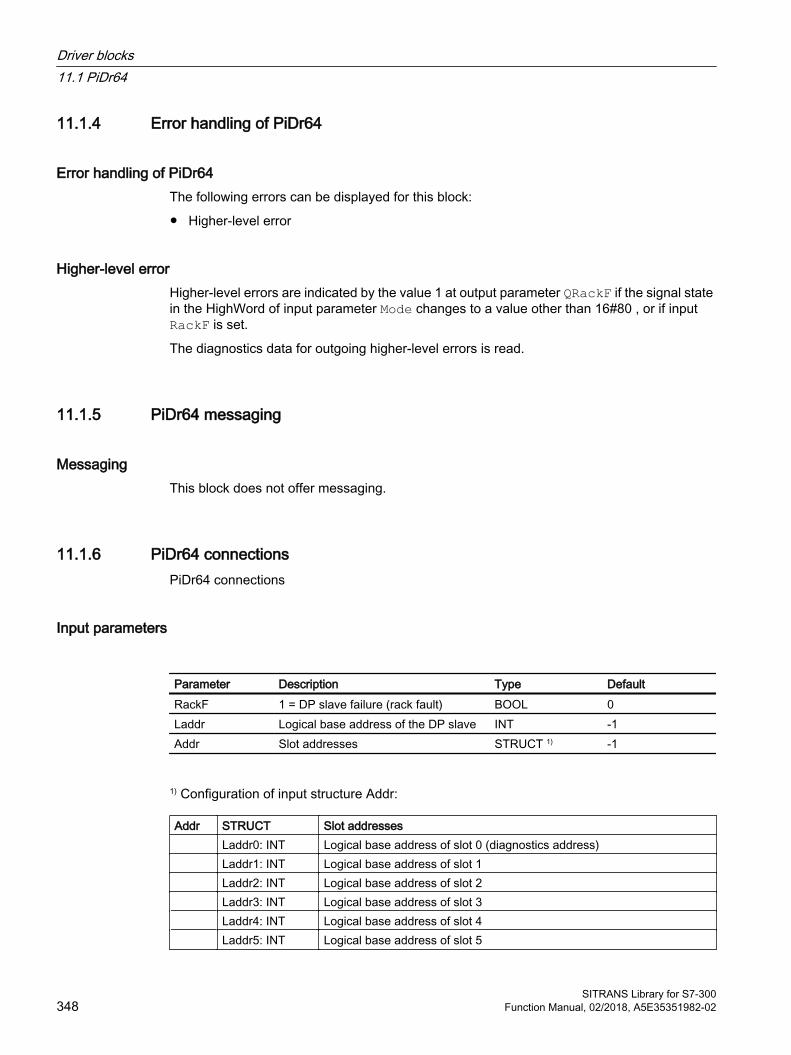
11.1.4 Error handling of PiDr64
Error handling of PiDr64 The following errors can be displayed for this block:
● Higher-level error
Higher-level errorHigher-level errors are indicated by the value 1 at output parameter QRackF if the signal state in the HighWord of input parameter Mode changes to a value other than 16#80 , or if input RackF is set.
The diagnostics data for outgoing higher-level errors is read.
11.1.5 PiDr64 messaging
Messaging This block does not offer messaging.
11.1.6 PiDr64 connectionsPiDr64 connections
Input parameters
Parameter Description Type DefaultRackF 1 = DP slave failure (rack fault) BOOL 0Laddr Logical base address of the DP slave INT -1Addr Slot addresses STRUCT 1) -1
1) Configuration of input structure Addr:
Addr STRUCT Slot addresses Laddr0: INT Logical base address of slot 0 (diagnostics address) Laddr1: INT Logical base address of slot 1 Laddr2: INT Logical base address of slot 2 Laddr3: INT Logical base address of slot 3 Laddr4: INT Logical base address of slot 4 Laddr5: INT Logical base address of slot 5
Driver blocks11.1 PiDr64
SITRANS Library for S7-300348 Function Manual, 02/2018, A5E35351982-02

Laddr6: INT Logical base address of slot 6 END_STRUCT
In/out parameters
Parameter Description Type DefaultMode Value status and measuring type DWORD 16#00000000
Output parameters
Parameter Description Type DefaultQRackF 1 = DP slave failure (rack fault) BOOL 0AcyclData Acyclic data STRUCT2) 0
2)Configuration of the output structure AcyclData:
AcyclDa‐ta
STRUCT Description
SlotRd : INT Number of the slot for read requests ReqRd : INT Request for reading the data record with this num‐
ber (-1 = no request) LenRd : INT Length in bytes of the data record to read SlotWr : INT Number of the slot for write requests ReqWr : INT Request for writing the data record with this number
(-1 = no request) LenWr : INT Length in bytes of the data record to write RdyRead : INT The data record with this number was read (-1 = no
data record read) RdyWrite : INT The data record with this number was written (-1 =
no data record written) RetValRd :
WORD Return value of SFB RDREC (SFB52) for the read
job RetValWr :
WORD Return value of SFB WRREC (SFB53) for the read
job Input STRUCT Data that was read from the DP slave Para0 : DWORD Value of input data … … Para15 : DWORD Value of input data END_STRUCT Output STRUCT Data to be written to the DP slave Para0 : DWORD Value of output data … … Para15 : DWORD Value of output data END_STRUCT
Driver blocks11.1 PiDr64
SITRANS Library for S7-300Function Manual, 02/2018, A5E35351982-02 349
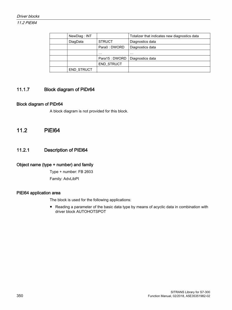
NewDiag : INT Totalizer that indicates new diagnostics data DiagData STRUCT Diagnostics data Para0 : DWORD Diagnostics data … … Para15 : DWORD Diagnostics data END_STRUCT END_STRUCT
11.1.7 Block diagram of PiDr64
Block diagram of PiDr64A block diagram is not provided for this block.
11.2 PiEl64
11.2.1 Description of PiEl64
Object name (type + number) and family Type + number: FB 2603
Family: AdvLibPI
PiEl64 application area The block is used for the following applications:
● Reading a parameter of the basic data type by means of acyclic data in combination with driver block AUTOHOTSPOT
Driver blocks11.2 PiEl64
SITRANS Library for S7-300350 Function Manual, 02/2018, A5E35351982-02
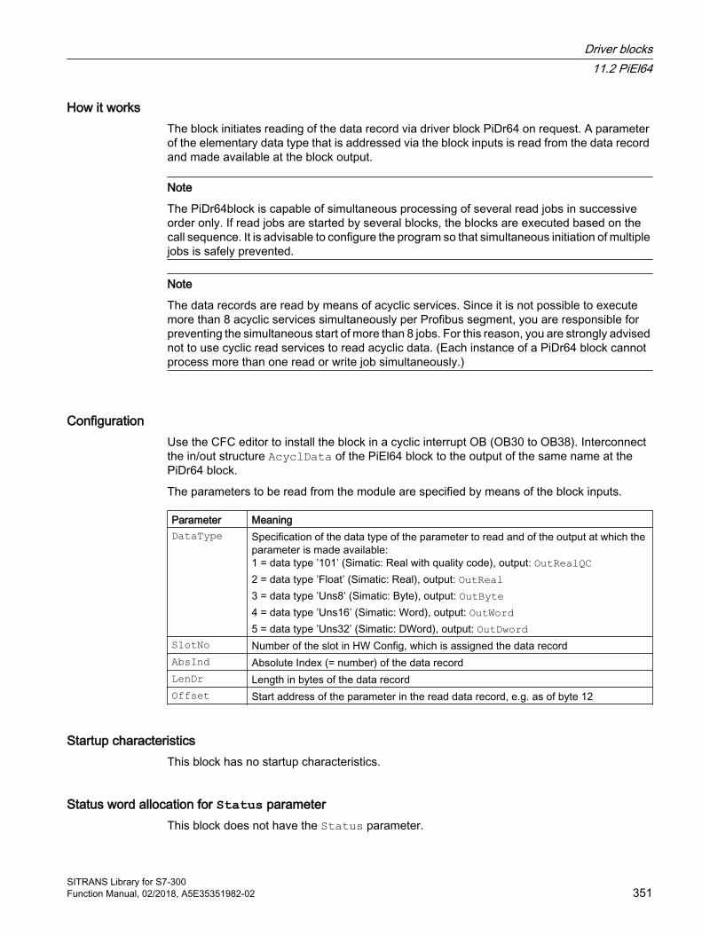
How it works The block initiates reading of the data record via driver block PiDr64 on request. A parameter of the elementary data type that is addressed via the block inputs is read from the data record and made available at the block output.
Note
The PiDr64block is capable of simultaneous processing of several read jobs in successive order only. If read jobs are started by several blocks, the blocks are executed based on the call sequence. It is advisable to configure the program so that simultaneous initiation of multiple jobs is safely prevented.
Note
The data records are read by means of acyclic services. Since it is not possible to execute more than 8 acyclic services simultaneously per Profibus segment, you are responsible for preventing the simultaneous start of more than 8 jobs. For this reason, you are strongly advised not to use cyclic read services to read acyclic data. (Each instance of a PiDr64 block cannot process more than one read or write job simultaneously.)
Configuration Use the CFC editor to install the block in a cyclic interrupt OB (OB30 to OB38). Interconnect the in/out structure AcyclData of the PiEl64 block to the output of the same name at the PiDr64 block.
The parameters to be read from the module are specified by means of the block inputs.
Parameter MeaningDataType Specification of the data type of the parameter to read and of the output at which the
parameter is made available:1 = data type ’101’ (Simatic: Real with quality code), output: OutRealQC2 = data type ’Float’ (Simatic: Real), output: OutReal3 = data type ’Uns8’ (Simatic: Byte), output: OutByte4 = data type ’Uns16’ (Simatic: Word), output: OutWord5 = data type ’Uns32’ (Simatic: DWord), output: OutDword
SlotNo Number of the slot in HW Config, which is assigned the data recordAbsInd Absolute Index (= number) of the data recordLenDr Length in bytes of the data recordOffset Start address of the parameter in the read data record, e.g. as of byte 12
Startup characteristics This block has no startup characteristics.
Status word allocation for Status parameter This block does not have the Status parameter.
Driver blocks11.2 PiEl64
SITRANS Library for S7-300Function Manual, 02/2018, A5E35351982-02 351
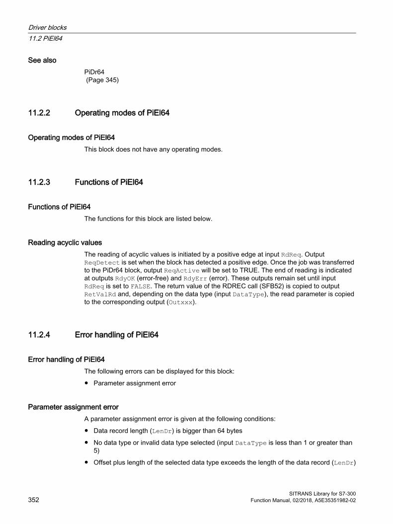
See alsoPiDr64 (Page 345)
11.2.2 Operating modes of PiEl64
Operating modes of PiEl64 This block does not have any operating modes.
11.2.3 Functions of PiEl64
Functions of PiEl64 The functions for this block are listed below.
Reading acyclic valuesThe reading of acyclic values is initiated by a positive edge at input RdReq. Output ReqDetect is set when the block has detected a positive edge. Once the job was transferred to the PiDr64 block, output ReqActive will be set to TRUE. The end of reading is indicated at outputs RdyOK (error-free) and RdyErr (error). These outputs remain set until input RdReq is set to FALSE. The return value of the RDREC call (SFB52) is copied to output RetValRd and, depending on the data type (input DataType), the read parameter is copied to the corresponding output (Outxxx).
11.2.4 Error handling of PiEl64
Error handling of PiEl64 The following errors can be displayed for this block:
● Parameter assignment error
Parameter assignment errorA parameter assignment error is given at the following conditions:
● Data record length (LenDr) is bigger than 64 bytes
● No data type or invalid data type selected (input DataType is less than 1 or greater than 5)
● Offset plus length of the selected data type exceeds the length of the data record (LenDr)
Driver blocks11.2 PiEl64
SITRANS Library for S7-300352 Function Manual, 02/2018, A5E35351982-02
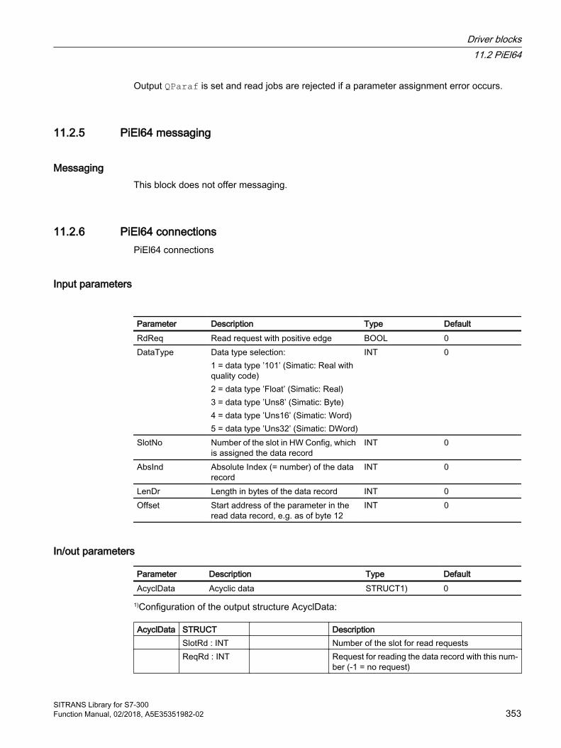
Output QParaf is set and read jobs are rejected if a parameter assignment error occurs.
11.2.5 PiEl64 messaging
Messaging This block does not offer messaging.
11.2.6 PiEl64 connectionsPiEl64 connections
Input parameters
Parameter Description Type DefaultRdReq Read request with positive edge BOOL 0DataType Data type selection:
1 = data type ’101’ (Simatic: Real with quality code)2 = data type ’Float’ (Simatic: Real)3 = data type ’Uns8’ (Simatic: Byte)4 = data type ’Uns16’ (Simatic: Word)5 = data type ’Uns32’ (Simatic: DWord)
INT 0
SlotNo Number of the slot in HW Config, which is assigned the data record
INT 0
AbsInd Absolute Index (= number) of the data record
INT 0
LenDr Length in bytes of the data record INT 0Offset Start address of the parameter in the
read data record, e.g. as of byte 12INT 0
In/out parameters
Parameter Description Type DefaultAcyclData Acyclic data STRUCT1) 0
1)Configuration of the output structure AcyclData:
AcyclData STRUCT Description SlotRd : INT Number of the slot for read requests ReqRd : INT Request for reading the data record with this num‐
ber (-1 = no request)
Driver blocks11.2 PiEl64
SITRANS Library for S7-300Function Manual, 02/2018, A5E35351982-02 353

LenRd : INT Length in bytes of the data record to read SlotWr : INT Number of the slot for write requests ReqWr : INT Request for writing the data record with this num‐
ber (-1 = no request) LenWr : INT Length in bytes of the data record to write RdyRead : INT The data record with this number was read (-1 =
no data record read) RdyWrite : INT The data record with this number was written (-1
= no data record written) RetValRd :
WORD Return value of SFB RDREC (SFB52) for the read
job RetValWr :
WORD Return value of SFB WRREC (SFB53) for the read
job Input STRUCT Data that was read from the DP slave Para0 : DWORD Value of input data … … Para15 : DWORD Value of input data END_STRUCT Output STRUCT Data to be written to the DP slave Para0 : DWORD Value of output data … … Para15 : DWORD Value of output data END_STRUCT NewDiag : INT Totalizer that indicates new diagnostics data DiagData STRUCT Diagnostics data Para0 : DWORD Diagnostics data … … Para15 : DWORD Diagnostics data END_STRUCT END_STRUCT
Output parameters
Parameter Description Type DefaultQParf 1 = parameter assignment error BOOL 0ReqDetect Read job detected BOOL 0ReqActive Read job is active, which means that it was
transferred to the PiDr64 blockBOOL 0
RdyOK 1 = parameter was read without error BOOL 0RdyErr 1 = error when reading the parameter BOOL 0RetValRd Return values of the RDREC block (SFB52) BOOL 0OutRealQC Read parameter of data type Real plus qual‐
ity codeSTRUCT● Value : REAL● ST: BYTE
-● 0.0● 16#80
Driver blocks11.2 PiEl64
SITRANS Library for S7-300354 Function Manual, 02/2018, A5E35351982-02

Parameter Description Type DefaultOutReal Read parameter of data type Real REAL 0.0OutByte Read parameter of data type Byte BYTE 16#00OutWord Read parameter of data type Word WORD 16#0000OutDword Read parameter of data type DWord DWORD 16#00000000
11.2.7 Block diagram of PiEl64
Block diagram of PiEl64A block diagram is not provided for this block.
11.3 PiStAr64
11.3.1 Description of PiStAr64
Object name (type + number) and family Type + number: FB 2604
Family: AdvLibPI
Area of application for PiStAr64 The block is used for the following applications:
● Reading a parameter of data type String or Array of Byte (OctStr) by means of acyclic data in combination with PiDr64 driver block.
How it works The block initiates reading of the data record via driver block PiDr64 on request. A parameter of the elementary data type that is addressed via the block inputs is read from the data record and made available at the block output.
Note
The PiDr64block is capable of simultaneous processing of several read jobs in successive order only. If read jobs are started by several blocks, the blocks are executed based on the call sequence. It is advisable to configure the program so that simultaneous initiation of multiple jobs is safely prevented.
Driver blocks11.3 PiStAr64
SITRANS Library for S7-300Function Manual, 02/2018, A5E35351982-02 355
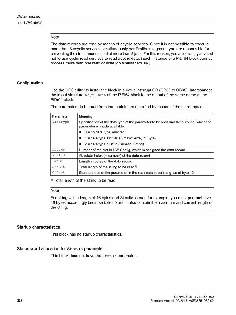
Note
The data records are read by means of acyclic services. Since it is not possible to execute more than 8 acyclic services simultaneously per Profibus segment, you are responsible for preventing the simultaneous start of more than 8 jobs. For this reason, you are strongly advised not to use cyclic read services to read acyclic data. (Each instance of a PiDr64 block cannot process more than one read or write job simultaneously.)
Configuration Use the CFC editor to install the block in a cyclic interrupt OB (OB30 to OB38). Interconnect the in/out structure AcyclData of the PiEl64 block to the output of the same name at the PiDr64 block.
The parameters to be read from the module are specified by means of the block inputs.
Parameter MeaningDataType Specification of the data type of the parameter to be read and the output at which the
parameter is made available:● 0 = no data type selected● 1 = data type ’OctStr’ (Simatic: Array of Byte)● 2 = data type ’VisStr’ (Simatic: String)
SlotNo Number of the slot in HW Config, which is assigned the data recordAbsInd Absolute Index (= number) of the data recordLenDr Length in bytes of the data recordStrLen Total length of the string to be read 1)
Offset Start address of the parameter in the read data record, e.g. as of byte 12
1) Total length of the string to be read:
Note
For string with a length of 16 bytes and Simatic format, for example, you must parameterize 18 bytes accordingly because bytes 0 and 1 also contain the maximum and current length of the string.
Startup characteristics This block has no startup characteristics.
Status word allocation for Status parameter This block does not have the Status parameter.
Driver blocks11.3 PiStAr64
SITRANS Library for S7-300356 Function Manual, 02/2018, A5E35351982-02

11.3.2 Operating modes of PiStAr64
Operating modes of PiStAr64 This block does not have any operating modes.
11.3.3 Functions of PiStAr64
Functions of PiStAr64 The functions for this block are listed below.
Reading acyclic valuesThe reading of acyclic values is initiated by a positive edge at input RdReq. Output ReqDetect is set when the block has detected a positive edge. Once the job was transferred to the PiDr64 block, output ReqActive will be set to TRUE. The end of reading is indicated at outputs RdyOK (error-free) and RdyErr (error). These outputs remain set until input RdReq is set to FALSE. The return value of the RDREC call (SFB52) is copied to output RetValRd and, depending on the data type (input DataType), the read parameter is copied to the corresponding output (OuStruct/OuString).
11.3.4 Error handling of PiStAr64
Error handling of PiStAr64 The following errors can be displayed for this block:
● Parameter assignment error
Parameter assignment errorA parameter assignment error is given at the following conditions:
● Data record length (LenDr) is bigger than 64 bytes
● No data type or invalid data type selected (input DataType is less than 1 or greater than 2)
● Offset plus length of the string (StrLen) exceeds the length of the data record (LenDr)
Output QParaf is set and read jobs are rejected if a parameter assignment error occurs.
Driver blocks11.3 PiStAr64
SITRANS Library for S7-300Function Manual, 02/2018, A5E35351982-02 357
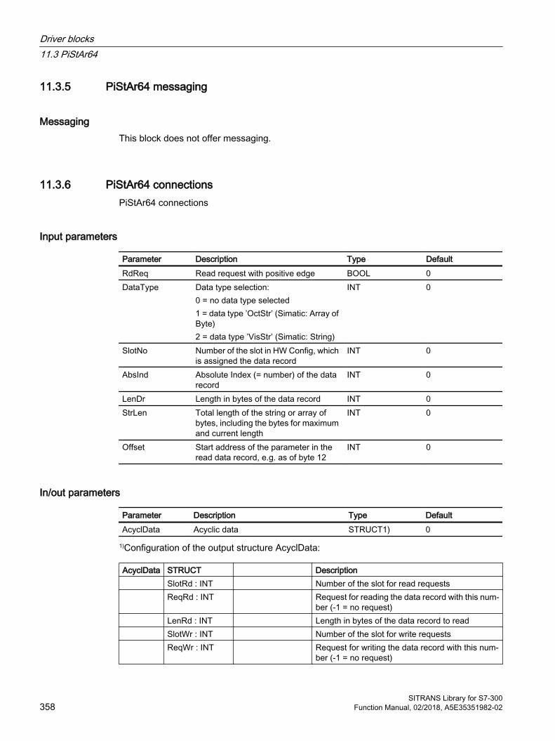
11.3.5 PiStAr64 messaging
Messaging This block does not offer messaging.
11.3.6 PiStAr64 connectionsPiStAr64 connections
Input parameters
Parameter Description Type DefaultRdReq Read request with positive edge BOOL 0DataType Data type selection:
0 = no data type selected1 = data type ’OctStr’ (Simatic: Array of Byte)2 = data type ’VisStr’ (Simatic: String)
INT 0
SlotNo Number of the slot in HW Config, which is assigned the data record
INT 0
AbsInd Absolute Index (= number) of the data record
INT 0
LenDr Length in bytes of the data record INT 0StrLen Total length of the string or array of
bytes, including the bytes for maximum and current length
INT 0
Offset Start address of the parameter in the read data record, e.g. as of byte 12
INT 0
In/out parameters
Parameter Description Type DefaultAcyclData Acyclic data STRUCT1) 0
1)Configuration of the output structure AcyclData:
AcyclData STRUCT Description SlotRd : INT Number of the slot for read requests ReqRd : INT Request for reading the data record with this num‐
ber (-1 = no request) LenRd : INT Length in bytes of the data record to read SlotWr : INT Number of the slot for write requests ReqWr : INT Request for writing the data record with this num‐
ber (-1 = no request)
Driver blocks11.3 PiStAr64
SITRANS Library for S7-300358 Function Manual, 02/2018, A5E35351982-02

LenWr : INT Length in bytes of the data record to write RdyRead : INT The data record with this number was read (-1 =
no data record read) RdyWrite : INT The data record with this number was written (-1
= no data record written) RetValRd :
WORD Return value of SFB RDREC (SFB52) for the read
job RetValWr :
WORD Return value of SFB WRREC (SFB53) for the read
job Input STRUCT Data that was read from the DP slave Para0 : DWORD Value of input data … … Para15 : DWORD Value of input data END_STRUCT Output STRUCT Data to be written to the DP slave Para0 : DWORD Value of output data … … Para15 : DWORD Value of output data END_STRUCT NewDiag : INT Totalizer that indicates new diagnostics data DiagData STRUCT Diagnostics data Para0 : DWORD Diagnostics data … … Para15 : DWORD Diagnostics data END_STRUCT END_STRUCT
Output parameters
Parameter Description Type DefaultQParf 1 = parameter assignment error BOOL 0ReqDetect Read job detected BOOL 0ReqActive Read job is active, which means that it was
transferred to the PiDr64 blockBOOL 0
RdyOK 1 = parameter was read without error BOOL 0RdyErr 1 = error when reading the parameter BOOL 0RetValRd Return values of the RDREC block (SFB52) BOOL 0OuStruct Read array of bytes (OctStr) STRUCT
● Byte00: BYTE…● Byte59: BYTE
-● 16#00…● 16#00
OuString Read string STRING[48] ’’
Driver blocks11.3 PiStAr64
SITRANS Library for S7-300Function Manual, 02/2018, A5E35351982-02 359

11.3.7 Block diagram of PiStAr64
Block diagram of PiStAr64A block diagram is not provided for this block.
Driver blocks11.3 PiStAr64
SITRANS Library for S7-300360 Function Manual, 02/2018, A5E35351982-02

Index
00-1 edge transition, 25
AActivating limit monitoring
S7Mag6T, 213Area of application
FbMag6T, 263PiDr64, 345PiEl64, 350PiStAr64, 355S7Mag6T, 205SiFC43Dr, 96SipPS2, 271SitransP, 167SitrFC43, 35SitrLRHA, 319SitrLRPA, 105SitrP_PA, 133
Associated valuesSipPS2, 180, 292SitrFC43, 145
BBatch view, 9Block diagram
FbMag6T, 270PiDr64, 350PiEl64, 355PiStAr64, 360S7Mag6T, 238SiFC43Dr, 103SitransP, 192SitrFC43, 73SitrLRHA, 336SitrLRPA, 122SitrP_PA, 155
Block iconPS7Mag6T, 263S7Mag6T, 254SipPS2, 317SitransP, 203SitrLRHA, 344SitrP_PA, 166
Bumpless, 29Bumpless switchover, 30
CCalled blocks
PS7Mag6T, 257Configuration
FbMag6T, 264PiDr64, 345PiEl64, 351PiStAr64, 356PS7Mag6T, 257S7Mag6T, 205SiFC43Dr, 96SipPS2, 271SitransP, 167SitrFC43, 35SitrLRHA, 319SitrLRPA, 105SitrP_PA, 133
Configuration dataS7Mag6T, 212SipPS2, 278SitransP, 171SitrLRHA, 322SitrLRPA, 108SitrP_PA, 138
Control system faultSitransP, 178
DDisplaying auxiliary values
SitrLRHA, 327Dosing view
S7Mag6T, 252SitrFC43, 92
EError handling
FbMag6T, 267PiDr64, 348PiEl64, 352PiStAr64, 357S7Mag6T, 221SipPS2, 290
SITRANS Library for S7-300Function Manual, 02/2018, A5E35351982-02 361
SitransP, 177SitrFC43, 49SitrLRPA, 113, 327SitrP_PA, 143
FFbMag6T
Area of application, 263Configuration, 264Error handling, 267Functions, 266Higher-level error, 267How it works, 264I/Os, 268Messaging, 267Module errors, 267Object name, 263Operating modes, 266Simulating signals, 267Startup characteristics, 266Status word allocation, 266
Feature, 23Pause in dosing in the event of a flow alarm, 29Specifying the reaction to exiting local mode, 28
FunctionsFbMag6T, 266PiDr64, 346PiEl64, 352PiStAr64, 357S7Mag6T, 211SipPS2, 278SitransP, 171SitrFC43, 43SitrLRHA, 322SitrLRPA, 108SitrP_PA, 137
GGradient monitoring
SitrFC43, 45Group error
SipPS2, 279
HHigher-level error
FbMag6T, 267PiDr64, 348
How it worksFbMag6T, 264PiDr64, 345PiEl64, 351PiStAr64, 355S7Mag6T, 205SiFC43Dr, 96SipPS2, 271SitransP, 167SitrFC43, 35SitrLRHA, 319SitrLRPA, 105SitrP_PA, 133
II/Os
FbMag6T, 268PiDr64, 348PiEl64, 353PiStAr64, 358S7Mag6T, 225SipPS2, 292SitransP, 181SitrFC43, 53SitrLRPA, 116, 330SitrP_PA, 146
Instance-specific messagesSitransP, 179SitrFC43, 52, 145SitrLRHA, 329SitrLRPA, 115
InterlocksSipPS2, 279
LLimit monitoring
S7Mag6T, 213SitransP, 173SitrFC43, 44SitrLRHA, 323SitrLRPA, 109SitrP_PA, 138
Limit viewS7Mag6T, 246SipPS2, 310SitransP, 196SitrFC43, 80SitrLRHA, 341
Local mode, 30
Index
SITRANS Library for S7-300362 Function Manual, 02/2018, A5E35351982-02
MMessage suppression
S7Mag6T, 213Message view, 10Messaging
FbMag6T, 267PiDr64, 348PiEl64, 353PiStAr64, 358S7Mag6T, 223SipPS2, 291SitransP, 178SitrFC43, 50SitrLRHA, 328SitrLRPA, 113
Mode switchover errorS7Mag6T, 222SipPS2, 290
Module errorsFbMag6T, 267
NNot bumpless, 29
OObject name
FbMag6T, 263PiDr64, 345PiEl64, 350PiStAr64, 355S7Mag6T, 205SipPS2, 271SitransP, 167SitrLRHA, 319SitrLRPA, 105SitrP_PA, 133
Operating modesFbMag6T, 266PiDr64, 346PiEl64, 352PiStAr64, 357S7Mag6T, 210SiFC43Dr, 97SipPS2, 277SitransP, 171SitrLRHA, 322
SitrLRPA, 108SitrP_PA, 136
Operator authorizationsSipPS2, 285SitrFC43, 46
Operator permissionsS7Mag6T, 215
Overview of error numbersS7Mag6T, 221SipPS2, 290SitransP, 177SitrLRHA, 327SitrLRPA, 113SitrP_PA, 143
PParameter assignment error
PiEl64, 352PiStAr64, 357
Parameter viewS7Mag6T, 248SipPS2, 313SITRANS P, 199SitrLRHA, 342SitrLRPA, 130SitrP_PA, 162
Pause in dosing in the event of a flow alarm, 29PiDr64
Area of application, 345Block diagram, 350Configuration, 345Error handling, 348Functions, 346Higher-level error, 348How it works, 345I/Os, 348Messaging, 348Object name, 345Operating modes, 346Simulating signals, 347Startup characteristics, 346Status word allocation, 346
PiEl64Area of application, 350Block diagram, 355Configuration, 351Error handling, 352Functions, 352How it works, 351I/Os, 353Messaging, 353
Index
SITRANS Library for S7-300Function Manual, 02/2018, A5E35351982-02 363
Object name, 350Operating modes, 352Parameter assignment error, 352Startup characteristics, 351Status word allocation, 351
PiStAr64Area of application, 355Block diagram, 360Configuration, 356Error handling, 357Functions, 357How it works, 355I/Os, 358Messaging, 358Object name, 355Operating modes, 357Parameter assignment error, 357Startup characteristics, 356Status word allocation, 356
Process control errorSipPS2, 291SitransP, 178SitrFC43, 50, 144SitrLRHA, 328SitrLRPA, 114SitrP_PA, 143
Process control faultS7Mag6T, 223
Process messagesS7Mag6T, 224SipPS2, 292SitransP, 178SitrFC43, 50, 144SitrLRHA, 328SitrLRPA, 114
PS7Mag6TBlock icon, 263Called blocks, 257Configuration, 257Function, 256Startup characteristics, 257
RResult of the limit monitoring
S7Mag6T, 213
SS7Mag6T
Activating limit monitoring, 213
Area of application, 205Block diagram, 238Block icon, 254Configuration, 205Configuration data, 212Error handling, 221Functions, 211How it works, 205I/Os, 225Limit monitoring, 213Message suppression, 213Messaging, 223Mode switchover error, 222Object name, 205Operating modes, 210Operator permissions, 215Overview of error numbers, 221Preview, 249Process control fault, 223Process messages, 224Result of the limit monitoring, 213Startup characteristics, 206Status word allocation, 206
SiFC43DrArea of application, 96Block diagram, 103Configuration, 96How it works, 96Operating modes, 97Startup characteristics, 96
Simulating signalsFbMag6T, 267PiDr64, 347SitrLRHA, 326
SipPS2Area of application, 271Associated values, 180, 292Block icon, 317Configuration, 271Configuration data, 278Dynamic monitoring, 281Error handling, 290Forcing operating modes, 280Functions, 278Group error, 279How it works, 271I/Os, 292Interlocks, 279Messaging, 291Mode switchover error, 290Neutral position, 283Object name, 271
Index
SITRANS Library for S7-300364 Function Manual, 02/2018, A5E35351982-02
Operating modes, 277Operator authorizations, 285Overview of error numbers, 290Preview, 315Process control error, 291Process messages, 292Selecting a unit of measure, 283Specifying control valve positions, 280Startup characteristics, 272Static monitoring, 282Status word allocation, 272
SitransPArea of application, 167Block diagram, 192Block icon, 203Configuration, 167Configuration data, 171Control system fault, 178Error handling, 177Functions, 171How it works, 167I/Os, 181Instance-specific messages, 179Limit monitoring, 173Messaging, 178Object name, 167Operating modes, 171Overview of error numbers, 177Preview, 200Process control error, 178Process messages, 178Slave pointer view, 202Startup characteristics, 168Status word allocation, 168
SitrFC43Area of application, 35Associated values, 145Block diagram, 73Configuration, 35Error handling, 49Functions, 43Gradient monitoring, 45How it works, 35I/Os, 53Instance-specific messages, 52, 145Limit monitoring, 44Messaging, 50Operator authorizations, 46Process control error, 50, 144Process messages, 50, 144Startup characteristics, 36Status word allocation, 37
SitrLRHAArea of application, 319Block diagram, 336Block icon, 344Configuration, 319Configuration data, 322Displaying auxiliary values, 327Error handling, 327Functions, 322How it works, 319Instance-specific messages, 329Limit monitoring, 323Messaging, 328Object name, 319Operating modes, 322Overview of error numbers, 327Preview, 343Process control error, 328Process messages, 328Simulating signals, 326Startup characteristics, 320Status word allocation, 320
SitrLRPAArea of application, 105Block diagram, 122Block icon, 132Configuration, 105Configuration data, 108Error handling, 113How it works, 105I/Os, 116, 330Instance-specific messages, 115Limit monitoring, 109Messaging, 113Object name, 105Operating modes, 108Overview of error numbers, 113Preview, 131Process control error, 114Process messages, 114Startup characteristics, 106Status word allocation, 106
SitrP_PAArea of application, 133Block diagram, 155Block icon, 166Configuration, 133Configuration data, 138Error handling, 143Functions, 137How it works, 133I/Os, 146
Index
SITRANS Library for S7-300Function Manual, 02/2018, A5E35351982-02 365
Limit monitoring, 138Object name, 133Operating modes, 136Overview of error numbers, 143Preview, 163Process control error, 143Slave pointer view, 165Startup characteristics, 134Status word allocation, 134
Specifying the reaction to exiting local mode, 28Standard view
PS7Mag6T, 262S7Mag6T, 241SipPS2, 305SitransP, 194SitrLRHA, 338
Startup characteristics, 24FbMag6T, 266PiDr64, 346PiEl64, 351PiStAr64, 356PS7Mag6T, 257S7Mag6T, 206SiFC43Dr, 96SipPS2, 272SitransP, 168SitrFC43, 36SitrLRHA, 320SitrLRPA, 106SitrP_PA, 134
Status word allocationFbMag6T, 266PiDr64, 346PiEl64, 351PiStAr64, 356S7Mag6T, 206SipPS2, 272SitransP, 168SitrFC43, 37SitrLRHA, 320SitrLRPA, 106SitrP_PA, 134
TTrend view, 11
Index
SITRANS Library for S7-300366 Function Manual, 02/2018, A5E35351982-02