siwarex r load cells - siemens ag r load cells operating manual ... • equipment for monitoring...
TRANSCRIPT

s
SIWAREX R Load Cells
Operating Instructions Edition 06/2009

SIWAREX R Load Cells Operating Manual A5E00159640 2
Table of Contents:
Safety Instructions............................................................................ 3
General Information.......................................................................... 4
Notes on product liability................................................................. 4
1 Technical Description....................................................................... 5 1.1 Area of Application.............................................................................. 5
1.2 Structure ............................................................................................. 5
1.3 System Configuration.......................................................................... 7
2 Installation/Assembly..................................................................... 10 2.1 Installation......................................................................................... 10
2.2 Assembly .......................................................................................... 13
2.3 Disassembly...................................................................................... 16
3 Commissioning............................................................................... 17
4 Service ............................................................................................. 19 4.1 Care and Maintenance...................................................................... 19
4.2 Troubleshooting ................................................................................ 19
5 Technical Data................................................................................. 22 5.1 Functional Data................................................................................. 22
5.2 Unit Version ...................................................................................... 24
5.3 Explosion Protection ......................................................................... 25
5.4 Electromagnetic Compatibility........................................................... 26
5.5 Dimensions ....................................................................................... 27
6 Ordering Data .................................................................................. 34

SIWAREX R Load Cells Operating Manual A5E00159640 3
Safety Instructions
DANGER
indicates that death, severe personal injury or substantial property damage will result if proper precautions are not taken.
WARNING
indicates that death or severe personal injury can result if proper precautions are not taken.
CAUTION
This text accompanied by a warning triangle indicates that minor personal injury can result if proper precautions are not taken.
CAUTION
This text without an accompanying warning triangle means that property damage may occur if proper precautions are not taken.
ATTENTION
indicates that an undesirable result or state may result if the proper steps are not taken.
NOTE
indicates a potential benefit if recommendations are followed. Qualified personnel as used in the safety instructions in this manual and on the
product itself are individuals who are familiar with the installation, assembly, initial start-up and operation of this product. They must be authorized and qualified to install, start and maintain devices, systems and circuits in accordance with national safety rules and regulations.
Copyright © Siemens AG 2009 All rights reserved The reproduction, transmission or use of this document or its contents is not permitted without express written authority. Offenders will be liable for damages. All rights, including rights created by patent grant or registration of a utility model or design, are reserved. Siemens AG Bereich Automatisierungs- und Antriebstechnik Geschäftsgebiet Process Instrumentation and Analytics D-76181 Karlsruhe
Disclaimer of Liability We have checked the contents of this manual for agreement with the hardware and software described. Since deviations cannot be precluded entirely, we cannot guarantee full agreement. However, the data in this manual are reviewed regularly and any necessary corrections included in subsequent editions. Suggestions for improvement are welcomed. ©Siemens AG 2009 Technical data subject to change.

SIWAREX R Load Cells Operating Manual A5E00159640 4
General Information Use for the intended purpose
Use for the intended purpose means that this product may only be used within the limits of the technical specifications and statement of purpose of this operating manual. This device will not be a source of danger provided it is used for the intended purpose under consideration of the safety instructions. Perfect, safe operation of this device is conditional upon proper transport, storage, installation and assembly. Proper operation of this device can only be ensured if the specifications provided in technical data are observed. Improper handling can result in death, severe personal injury and property damage.
Notes on product liability We expressly point out that the nature of the product is described exclusively and conclusively in the contract of sale. The contents of this product documentation are not part of an earlier or existing agreement, acceptance or legal relationship nor do they affect these in any way. The particular contract of sale determines the sum of obligations to be met by Siemens and the guarantee regulation container therein is complete and is the sole regulation that shall apply. This contractual guarantee regulation is neither extended nor limited by the information provided in this document.
Information on delivery The scope of delivery in accordance with the valid contract of sale is listed in the shipping documents enclosed in the delivery. Please observe any relevant instructions when opening the packaging. Check the shipment for completeness and possible transportation damage. In particular, compare the order number on the rating plate with the order information. Please read this operating manual before starting work! It contains important information and data that, if observed, ensure the overall safety and functionality of this device. Following these instructions will make it easier for you to use handle this product and ensure reliable measuring results.

SIWAREX R Load Cells Operating Manual A5E00159640 5
1 Technical Description 1.1 Area of Application
SIWAREX R load cells are used for static and dynamic measurements of forces and weights. They can be used for almost all applications in industrial weighing technology. These may be for example: • container, hopper or platform scales, • rollway, belt or crane scales, • filling/packing plants, proportioning and mixing, • filling level and completeness inspection, • equipment for monitoring pressing and clamping procedures, • dynamic scales All applications can be located in areas with mandatory calibration or in hazardous areas.
1.2 Structure The SIWAREX R load cells are equipped with wire strain gauges (WSG). WSG load cells are transducers for converting mechanical forces into electrical signals. The functional principle is always the same despite different designs. The basic element is a special spring body. The spring body is deformed elastically when a force is applied. The integrated WSGs then change their ohmic resistance (figure 1-1)
Figure 1-1 Principle diagram shown by the example of a bending rod load cell

Edition 06/2009 Technical Description
SIWAREX R Load Cells Operating Manual A5E00159640 6
At least four WSGs per load cell are connected in a full Wheatstone bridge. The stretched or upset WSGs are wired so that the positive or negative changes in resistance add up to a total upset of the bridge. The feed voltage (in 6-wire technology also the sensor voltage, SENSE) is applied at one bridge diagonal. The measuring voltage is tapped at the other diagonal. At a constant feed voltage (EXC), the measured voltage (SIG) changes proportionally to the applied load (figure 1-2). In practice load cells contain other resistors for temperature compensation, zero point and parameter adjustment. These may be in the input or output of the load cell depending on the type and on requirements.
Figure 1-2 Principle diagram of a Wheatstone bridge The SIWAREX R load cells are usually made of high-grade steel and are welded hermetically sealed. This provides high corrosion protection and protection rating. Most series are licensed for use in scales with mandatory calibration of class III according to DIN EN 45501 and comply with OIML R60 3000d. Load cells with greater accuracy and/or EEx (i) approval are available on request. SIWAREX R load cells are electrically calibrated as standard. As a result, no reference load adjustment is necessary for example when commissioning a platform scales. A load cell can also be exchanged without readjustment. An exception to this rule is the series K and possibly load cells delivered outside the standard scope of delivery. The respective technical data apply for these load cell types.
Edition 06/2009 Technical Description
SIWAREX R Load Cells Operating Manual A5E00159640 7
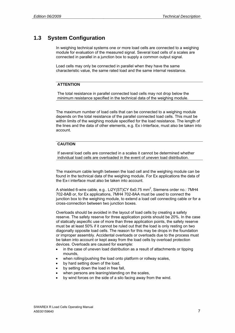
1.3 System Configuration In weighing technical systems one or more load cells are connected to a weighing module for evaluation of the measured signal. Several load cells of a scales are connected in parallel in a junction box to supply a common output signal. Load cells may only be connected in parallel when they have the same characteristic value, the same rated load and the same internal resistance. ATTENTION
The total resistance in parallel connected load cells may not drop below the minimum resistance specified in the technical data of the weighing module.
The maximum number of load cells that can be connected to a weighing module depends on the total resistance of the parallel connected load cells. This must be within limits of the weighing module specified for the load resistance. The length of the lines and the data of other elements, e.g. Ex i-Interface, must also be taken into account. CAUTION
If several load cells are connected in a scales it cannot be determined whether individual load cells are overloaded in the event of uneven load distribution.
The maximum cable length between the load cell and the weighing module can be found in the technical data of the weighing module. For Ex applications the data of the Ex-i interface must also be taken into account. A shielded 6-wire cable, e.g.. Li2Y(ST)CY 6x0.75 mm2, Siemens order no.: 7MH4 702-8AB or, for Ex applications, 7MH4 702-8AA must be used to connect the junction box to the weighing module, to extend a load cell connecting cable or for a cross-connection between two junction boxes. Overloads should be avoided in the layout of load cells by creating a safety reserve. The safety reserve for three application points should be 20%. In the case of statically aspecific use of more than three application points, the safety reserve must be at least 50% if it cannot be ruled out that the load is only resting on two diagonally opposite load cells. The reason for this may be drops in the foundation or improper assembly. Accidental overloads or overloads due to the process must be taken into account or kept away from the load cells by overload protection devices. Overloads are caused for example: • in the case of uneven load distribution as a result of attachments or tipping
mounds, • when rolling/pushing the load onto platform or rollway scales, • by hard setting down of the load, • by setting down the load in free fall, • when persons are leaning/standing on the scales, • by wind forces on the side of a silo facing away from the wind.
Edition 06/2009 Technical Description
SIWAREX R Load Cells Operating Manual A5E00159640 8
Overloads may also occur in lifting direction when the force application is permanently mounted to the load cell such as elastomer bearings on load cells of series BB. Lift off protection is necessary where there is a risk of the load carrier lifting off or tipping over. This is essential for lightweight containers or high silos outdoors. CAUTION
Overload protection devices must always be provided for load cells with low rated loads to protect the cells from being damaged. Use of the load cells beyond the maximum working load or maximum transverse load can lead to irreparable faults and even breakage of the load cell. Load cells may not be overloaded, e.g. by tightening screws, when adding installation components.
NOTE
If load cells are loaded beyond their rated load this can lead to an error message in the weighing module. If load surges during the measuring mode cannot be ruled out, for example when the load is set down in free fall, suitable precautions must be taken to avoid damage to the load cell (e.g. elastomer bearings or higher load cells).
The load must be applied in exact measuring direction of the load cell. Torsion and bending torques, off-center loads and transverse loads are disturbances which on the one hand falsify the measuring result and on the other hand can damage the load cell when they exceed the permissible limits. Load cells must therefore be installed with suitable installation components (e.g. SIWAREX R installation components). The possible errors mentioned above are then largely avoided. The installation components allow enough freedom of movement to prevent heat expansion leading to transverse loads. Transverse forces such as are caused by wind, acceleration or conveyor belt friction must be compensated by deflections or stops. Deflections must be installed exactly vertical to the direction of action of the load cells so that no force components occur in measuring direction. The deflections must be installed in such a way that they do not twist for example when the application points expand. This is most easily avoided by arranging the deflections in the same direction of rotation. The deflections to be installed should correspond to the principles used in weighing technology. Ball-jointed deflections are available for most SIWAREX R combi-installation units. Ball bolt deflectors up to a transverse load of 1000 kN are available on request. No parallel forces may be applied by filling and emptying devices and supply lines.
Edition 06/2009 Technical Description
SIWAREX R Load Cells Operating Manual A5E00159640 9
DANGER
Load cells are machine elements not constructed with the usual safety factors. Therefore appropriate crash protection or catastrophe protection must be provided which suit the danger potential.
CAUTION
For protection against undesirable electrical currents such as they occur when welding or from lightning, the load cells must be bridged with a highly flexible grounding cable (e.g. SIWAREX R grounding cable 7MH3 701-1AA1).
The substructure must withstand the planned loads. The application surface must have a roughness of a max. 1.6 µm. The values in the technical data must be observed for the ambient conditions. Note
The load cell must be protected from direct sunlight. The permissible operating temperature could otherwise be exceeded and thus the accuracy impaired.
SIWAREX R Load Cells Operating Manual A5E00159640 10
2 Installation/Assembly
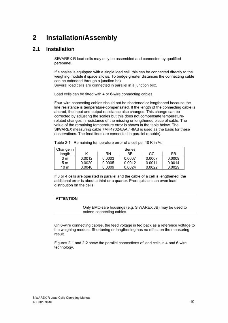
2.1 Installation SIWAREX R load cells may only be assembled and connected by qualified personnel. If a scales is equipped with a single load cell, this can be connected directly to the weighing module if space allows. To bridge greater distances the connecting cable can be extended through a junction box. Several load cells are connected in parallel in a junction box. Load cells can be fitted with 4 or 6-wire connecting cables. Four-wire connecting cables should not be shortened or lengthened because the line resistance is temperature-compensated. If the length of the connecting cable is altered, the input and output resistance also changes. This change can be corrected by adjusting the scales but this does not compensate temperature-related changes in resistance of the missing or lengthened piece of cable. The value of the remaining temperature error is shown in the table below. The SIWAREX measuring cable 7MH4702-8AA / -8AB is used as the basis for these observations. The feed lines are connected in parallel (double). Table 2-1 Remaining temperature error of a cell per 10 K in %:
Change in Series length K RN BB CC SB 3 m 0.0012 0.0003 0.0007 0.0007 0.0009 5 m 0.0020 0.0005 0.0012 0.0011 0.0014 10 m 0.0040 0.0009 0.0024 0.0022 0.0029
If 3 or 4 cells are operated in parallel and the cable of a cell is lengthened, the additional error is about a third or a quarter. Prerequisite is an even load distribution on the cells. ATTENTION
Only EMC-safe housings (e.g. SIWAREX JB) may be used to extend connecting cables.
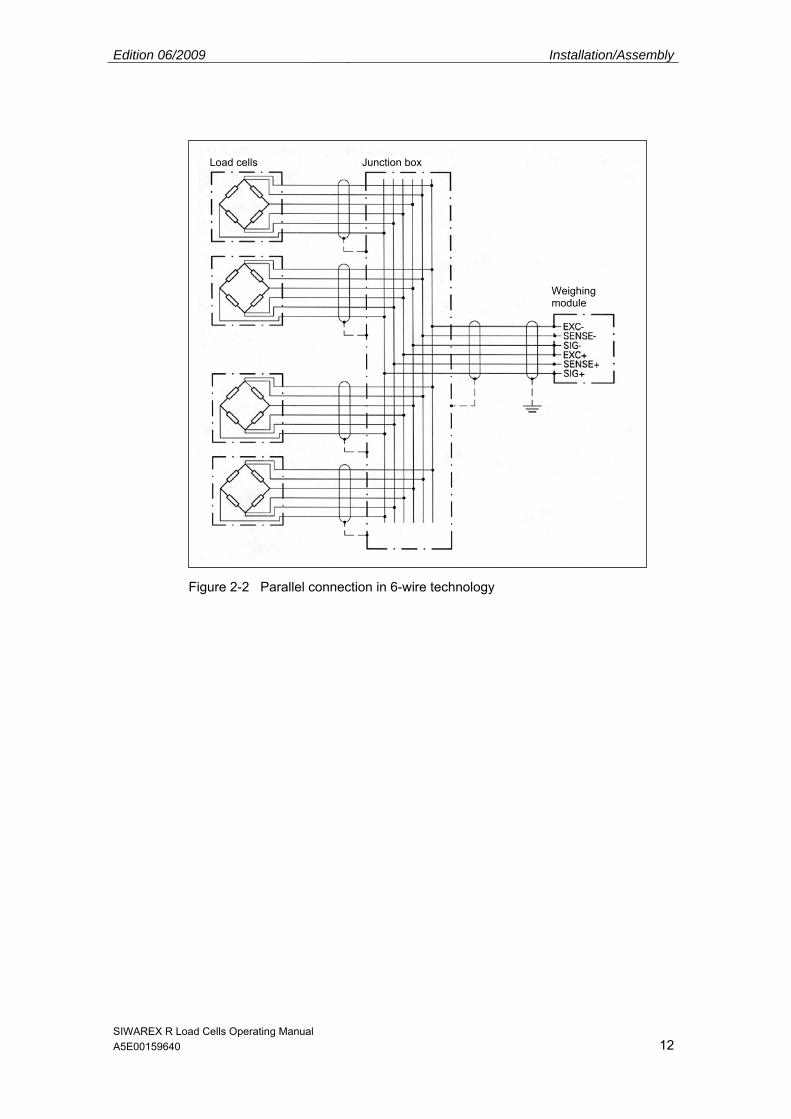
On 6-wire connecting cables, the feed voltage is fed back as a reference voltage to the weighing module. Shortening or lengthening has no effect on the measuring result. Figures 2-1 and 2-2 show the parallel connections of load cells in 4 and 6-wire technology.

Edition 06/2009 Installation/Assembly
SIWAREX R Load Cells Operating Manual A5E00159640 11
ATTENTION
If load cells with 4-wire connecting cables are used, two bridges must be inserted additionally: Bridge 1: EXC- to SENSE- Bridge 2: EXC+ to SENSE+
Figure 2-1 Parallel connection in 4-wire technology
Load cells Junction box
Weighing module
Edition 06/2009 Installation/Assembly
SIWAREX R Load Cells Operating Manual A5E00159640 12
Figure 2-2 Parallel connection in 6-wire technology
Load cells Junction box
Weighing module
Edition 06/2009 Installation/Assembly
SIWAREX R Load Cells Operating Manual A5E00159640 13
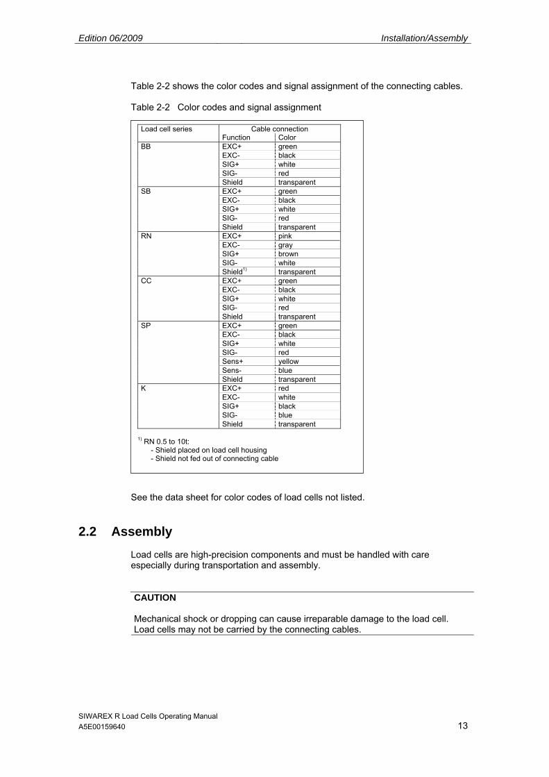
Table 2-2 shows the color codes and signal assignment of the connecting cables. Table 2-2 Color codes and signal assignment
See the data sheet for color codes of load cells not listed.
2.2 Assembly Load cells are high-precision components and must be handled with care especially during transportation and assembly. CAUTION
Mechanical shock or dropping can cause irreparable damage to the load cell. Load cells may not be carried by the connecting cables.
Load cell series Cable connection Function Color BB EXC+ green EXC- black SIG+ white SIG- red Shield transparent SB EXC+ green EXC- black SIG+ white SIG- red Shield transparent RN EXC+ pink EXC- gray SIG+ brown SIG- white Shield1) transparent CC EXC+ green EXC- black SIG+ white SIG- red Shield transparent SP EXC+ green EXC- black SIG+ white SIG- red Sens+ yellow Sens- blue Shield transparent K EXC+ red EXC- white SIG+ black SIG- blue Shield transparent
1) RN 0.5 to 10t:
- Shield placed on load cell housing - Shield not fed out of connecting cable

Edition 06/2009 Installation/Assembly
SIWAREX R Load Cells Operating Manual A5E00159640 14
As long as the assembly work on the scales has not been completed, the load cells should be replaced by dummies to protect them against impact or welding currents. CAUTION
If welding should be necessary after load cells have been installed, make absolutely sure that the welding current is not conducted through the load cell. The ground clamp of the welding gear should be attached directly next to the welding point with a safe contact. The load cells must be bridged with the grounding cable. The individual load cells must be disconnected.
Load cells may not be overloaded. The load carrier should be set down slowly. IN load cells with low rated loads in particular there is a danger that the load cell body could be distorted by application of force, e.g. tightening lock nuts. WARNING
Suitable lifting gear must be used for lifting the load carrier. The appropriate safety regulations must be observed.
The bearing is statically indefinite in the case of more than three load cells or application points. The force application points should be at the same height. The output signals of all load cells should be approximately the same at even load or correspond to the load distribution in the case of uneven load. Proceed as follows to measure the load on the load cells: • Disconnect load cell cables SIG+ and SIG-. • Supply load cells with the feed voltage (e.g. 10.2V). • Measure the output voltages between SIG+ and SIG- of the individual load
cells. The measured voltage corresponds in proportion to the product of characteristic value times supply voltage to the weight percentage at the rated load which is applied to the load cell. Example: feed voltage Us 10.2V characteristic value Cn 2mV/V rated load Emax 5t output voltage Ua 4mV Calculation: 4mV / (10,2V x 2mV/V) = 0.196 0.196 x 5t = 0.98t Result: The load cell is loaded with 0.98t
Spacer plates should be placed beneath the load cell with the lowest value until the output voltages are adjusted equally. The load cell seat must be horizontal, completely level and, like the load cell base, absolutely clean. The contact surfaces of the force applications must be lubricated with high-performance grease.

Edition 06/2009 Installation/Assembly
SIWAREX R Load Cells Operating Manual A5E00159640 15
If overload protection devices are available, these must be set so that they still accommodate the desired load safely. They must allow an unhindered increase in weight up to the nominal weight. Overload protection devices must be protected against soiling and freezing. The perfect functioning of overload protection devices must be checked in the course of regular maintenance work. DANGER
Soiled, frozen or incorrectly set overload protection devices block and lead to faulty measurements or can cause overflowing of the scales with property damage and injury to persons.
CAUTION
Correct assembly of the load cell and installation element must be checked by inspecting the installation dimensions and pendulum travel for example. Make sure the cable is not damaged or cut. The cable must be laid at the cable glands in the form of a vertical downward loop to avoid penetration by water.
CAUTION
The installation regulations of the installation element must also be taken into account in assembly.
Special features of bending ring scales series RN, RH, RC, RS
• Bending ring scales up to 13t are delivered with a pressure piece. The pressure piece is inserted in the load cell and secured against falling out by adhesive tape. It may not be lost when handling the load cell.
• Bending ring load cells have a very small measuring distance. An overload
protection is integrated in load cells with rated loads up to 13t. The standing area of the load cell restricts the movement of the force application tube. For this reason the standing area of the load cell must be checked carefully for soiling prior to installation. If there is a risk that the bottom of the load cell could become soiled or frozen, appropriate inspection and/or sealing measures must be taken. The bottom can be protected by a grease ring or sealing compound for example. When these measures are taken it must be considered that the force application also needs to be well sealed at the top of the load cell to effectively prevent penetration by moisture.

Edition 06/2009 Installation/Assembly
SIWAREX R Load Cells Operating Manual A5E00159640 16
2.3 Disassembly The same safety regulations and conditions apply for disassembly of the load cells as for installation and assembly. • Switch off all energy and power supplies. • Secure the load carrier against falling. • Use suitable lifting gear and tools. • Relieve load on the load cell and remove carefully without using force. • Do not cut the cable if the load cell is to be used again or sent in for repair. • Do not carry or pull the load cell by the cable.
SIWAREX R Load Cells Operating Manual A5E00159640 17
3 Commissioning The load cells are passive sensors. The manual of the weighing module should therefore be consulted primarily for commissioning. When using in the Ex area, the instructions for the Ex-i interface or Ex barrier must be observed. If the reference load of a scales needs to be checked, impermissibly great deviations in the weight display may occur in load cells which are not electrically calibrated. This reference load error can be electrically compensated. To do this, the individual measured values are adjusted to the smallest measured value by additional wiring. The resistors are connected in series with the load cell measuring signal. The measuring voltage is reduced by the appropriate resistance until it is equal to the smallest voltage. Because the resistors are connected in the measuring circuit, the temperature coefficient must be accordingly low (0.25ppm/K to 10ppm/K )
Example for reference load adjustment:
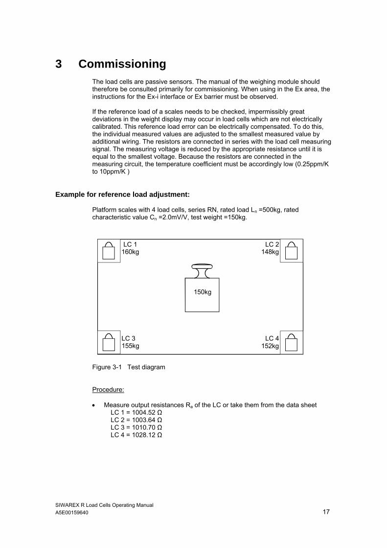
Platform scales with 4 load cells, series RN, rated load Ln =500kg, rated characteristic value Cn =2.0mV/V, test weight =150kg.
Figure 3-1 Test diagram Procedure: • Measure output resistances Ra of the LC or take them from the data sheet
LC 1 = 1004.52 Ω LC 2 = 1003.64 Ω LC 3 = 1010.70 Ω LC 4 = 1028.12 Ω
LC 1160kg
LC 2148kg
LC 4152kg
LC 3155kg
150kg

Edition 06/2009 Commissioning
SIWAREX R Load Cells Operating Manual A5E00159640 18
EXC+ 10VDC
EXC- 0VDC
SIG+
SIG+
SIG-
EXC+
EXC-
SIG-
LC 4EXC+
EXC-
SIG-
LC 3EXC+
EXC-
SIG-
LC 2EXC+
EXC-
SIG-
LC 1
R427 Ω
R347 Ω
R180 Ω
SIG+ SIG+ SIG+
• Apply test weight to all 4 corners and note values: LC 1 = 160kg LC 2 = 148kg LC 3 = 155kg LC 4 = 152kg
• Determine differences to the smallest value (148kg):
LC 1 - LC 2 = 160kg - 148kg = 12kg LC 3 - LC 2 = 155kg - 148kg = 7kg LC 4 - LC 2 = 152kg - 148kg = 4kg
• Calculate correction resistance:
Rcorr = Ra x Lerror / Ltest LC 1: Rcorr = R1 = 1004.52 Ω x 12kg / 150kg = approx. 80 Ω LC 2: smallest value -> no resistance necessary LC 3: Rcorr = R3 = 1010.70 Ω x 7kg / 150kg = approx.47 Ω LC 4: Rcorr = R4 = 1028.12 Ω x 4kg / 150kg = approx. 27 Ω
Rcorr = determined correction resistance (to be installed in the measuring line SIG+) Ra = output resistance of the load cells (can also be measured in the loaded state) Lerror = weight error (difference value from the smallest weight value) Ltest = test load (applied at all corners) • Install resistors and repeat test
Figure 3-2 Circuit diagram reference load adjustment
SIWAREX R Load Cells Operating Manual A5E00159640 19
4 Service 4.1 Care and Maintenance
Load cells are principally maintenance-free. However, regular inspections with checking of the force applications, pendulum limits, lift off and overload protections increase the reliability. The inspections should also be carried out after serious events such as thunderstorms, floods or earthquakes. If signs of corrosion appear, these can be counteracted by suitable protective coatings. Accumulation of dirt in the vicinity of a load cell should not be tolerated. When cleaning with a high-pressure water jet, the jet may not be directed at the cable gland or other sealing elements.
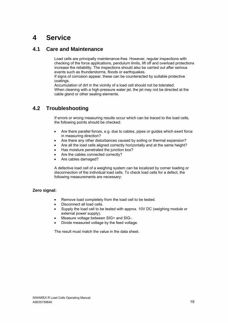
4.2 Troubleshooting If errors or wrong measuring results occur which can be traced to the load cells, the following points should be checked: • Are there parallel forces, e.g. due to cables, pipes or guides which exert force
in measuring direction? • Are there any other disturbances caused by soiling or thermal expansion? • Are all the load cells aligned correctly horizontally and at the same height? • Has moisture penetrated the junction box? • Are the cables connected correctly? • Are cables damaged? A defective load cell of a weighing system can be localized by corner loading or disconnection of the individual load cells. To check load cells for a defect, the following measurements are necessary:
Zero signal: • Remove load completely from the load cell to be tested. • Disconnect all load cells. • Supply the load cell to be tested with approx. 10V DC (weighing module or
external power supply). • Measure voltage between SIG+ and SIG-. • Divide measured voltage by the feed voltage. The result must match the value in the data sheet.
Edition 06/2009 Service
SIWAREX R Load Cells Operating Manual A5E00159640 20
Insulation resistance • Disconnect the load cell. • Connect all lines. • Measure insulation resistance between lines and load cell housing • Measure insulation resistance between lines and cable shield • Measure insulation resistance between cable shield and load cell housing (This
measurement is not possible in load cells in which the shield is connected to the load cell housing).
The insulation resistance must match the value in the technical data
Input and output resistance • Disconnect the load cell. • Measure the input resistance between EXC+ and EXC-. • Measure the output resistance between SIG+ and SIG-. The resistances must match the values in the data sheet or the technical data.
Bridge resistance • Disconnect load cell. • Measure resistance between SIG- and EXC- • Measure resistance between SIG+ and EXC+ The difference between the two values may not be greater than 1Ω. The measurement cannot be made in the series K load cell. DANGER
Measurements may not be made on the load cells in the Ex area.
CAUTION
Do not use ohmmeters which feed more voltage into the load cell than permitted in the technical data to measure the resistance.
A frequent cause of error which leads to failure of the load cells is their overloading. If overloading is diagnosed as the cause of the error, further measures are necessary. Damage is often caused by one of the following: 1. Dynamic overloading, e.g. by accidental falling of a relatively small weight onto
the load carrier from a great height. Possible remedies: • Fit shock-absorbing components, e.g. elastomer bearings • Overdimension the load cells

Edition 06/2009 Service
SIWAREX R Load Cells Operating Manual A5E00159640 21
2. Transverse forces, e.g. by pushing on or braking loads on a platform. Possible remedies: • Install deflectors • Install pendulum limits or set closer together.
NOTE
Only send in defective load cells to our repair workshop with an exact description of the error. This makes troubleshooting and analysis easier.
SIWAREX R Load Cells Operating Manual A5E00159640 22
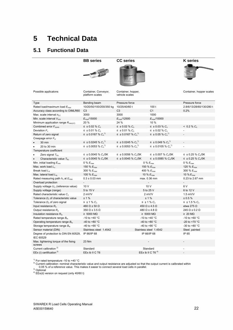
5 Technical Data 5.1 Functional Data BB series CC series K series
Possible applicatons Container, Conveyor, platform scales
Container, hopper, vehicle scales
Container, hopper scales
Type Bending beam Pressure force Pressure force Rated load/maximum load Emax 10/20/50/100/200/350 kg 10/25/40/60 t 100 t 2.8/6/13/28/60/130/280 t Accuracy class according to OIMLR60 C3 C3 C1 0.2% Max. scale interval nLC 3000 3000 1000 Min. scale interval Vmin Emax/15000 Emax/12500 Emax/10000 Minimum application range Rmin(LC) 20 % 24 % 10 % Combined error Fcomb ≤ ± 0.02 % Cn ≤ ± 0.02 % Cn ≤ ± 0.03 % Cn < 0.2 % Cn Deviation Fv ≤ ± 0.01 % Cn ≤ ± 0.01 % Cn ≤ ± 0.02 % Cn - Return of zero signal ≤ ± 0.0167 % Cn
1) ≤ ± 0.0167 % Cn1) ≤ ± 0.05 % Cn
1) - Creepage error Fcr • 30 min ≤ ± 0.0245 % Cn
1) ≤ ± 0.0245 % Cn1) ≤ ± 0.049 % Cn
1) - • 20 to 30 min ≤ ± 0.0053 % Cn
1) ≤ ± 0.0053 % Cn1) ≤ ± 0.0105 % Cn
1) - Temperature coefficient • Zero signal TKo ≤ ± 0.0045 % Cn/5K ≤ ± 0.0056 % Cn/5K ≤ ± 0.007 % Cn/5K ≤ ± 0.25 % Cn/5K • Characteristic value TKc ≤ ± 0.0045 % Cn/5K ≤ ± 0.0045 % Cn/5K ≤ ± 0.0085 % Cn/5K ≤ ± 0.25 % Cn/5K Min. initial loading Emin 0 % Emax 0 % Emax 0 % Emax Max. work load Lu 150 % Emax 150 % Emax 120 % Emax Break load Ld 300 % Emax 400 % Emax 300 % Emax Max. lateral load Llq 100 % Emax 10 % Emax 10 % Emax Rated measuring path hn at Emax 0.3 ± 0.03 mm max. 0.36 mm 0.23 to 2.67 mm Overload protection - - - Supply voltage Usr (reference value) 10 V 10 V 6 V Supply voltage (range) 5 to 15 V 5 to 25 V 6 to 12 V Rated characteristic value Cn 2 mV/V 2 mV/V 1.5 mV/V Tolerance Dc of characteristic value ± 1 % ± 1 % ± 0.5 % Tolerance Do of zero signal ≤ ± 1 % Cn ≤ ± 1 % Cn ≤ ± 1.5 % Cn Input resistance Re 460 Ω ± 50 Ω 450 Ω ± 4.5 Ω etwa 275 Ω Output resistance Ra 350 Ω ± 3.5 Ω 480 Ω ± 4.8 Ω 245 Ω ± 0.2 Ω Insulation resistance Ris ≥ 5000 MΩ ≥ 5000 MΩ ≥ 20 MΩ Rated temperature range Btn -10 to +40 °C -10 to +40 °C -10 to +60 °C Operating temperature range Btu -40 to +80 °C -40 to +80 °C -20 to +70 °C Storage temperature range Bts -40 to +90 °C -40 to +90 °C -30 to +80 °C Sensor material (DIN) Stainless steel 1.4542 Stainless steel 1.4542 Steel. painted Degree of protection to DIN EN 60529, IEC 60529
IP 66/IP 68 IP 66/IP 68 IP 65
Max. tightening torque of the fixing screws
23 Nm - -
Current calibration 2) Standard Standard - EEx (i) certification 3) EEx ib II C T6 EEx ib II C T6 4) -
1) For rated temperature -10 to +40 °C 2) Current calibration: nominal characteristic value and output resistance are adjusted so that the output current is calibrated within
0.05 % of a reference value. This makes it easier to connect several load cells in parallel. 3) Optional 4) EEx(d) version on request (only 40/60 t)

Edition 06/2009 Technical Data
SIWAREX R Load Cells Operating Manual A5E00159640 23
RN series SB series
Possible applicatons Container, conveyor, platform and roller table scales
Container, conveyor, overhead rail and platform scales
Type Bending ring Shear beam Rated load/maximum load Emax 60/130/280 kg 0.5/1/2/3.5/5/10 t 13/28/60 t 0.5/1/2/5 t Accuracy class according to OIMLR60 C3 C3 C3 C3 Max. scale interval nLC 3000 3000 3000 3000 Min. scale interval Vmin Emax/17500 Emax/10000 Emax/17500 Emax/10000 Minimum application range Rmin(LC) 17 % 30 % 17 % 30 % Combined error Fcomb ≤ ± 0.018 % Cn ≤ ± 0.023 % Cn ≤ ± 0.018 % Cn ≤ ± 0.02 % Cn Deviation Fv ≤ ± 0.01 % Cn ≤ ± 0.01 % Cn ≤ ± 0.01 % Cn ≤ ± 0.01 % Cn Return of zero signal ≤ ± 0.0167 % Cn
1) ≤ ± 0.0167 % Cn1) ≤ ± 0.0167 % Cn
1) ≤ ± 0.0167 % Cn1)
Creepage error Fcr • 30 min ≤ ± 0.0120 % Cn
1) ≤ ± 0.0245 % Cn1) ≤ ± 0.0120 % Cn
1) ≤ ± 0.0245 % Cn1)
• 20 to 30 min ≤ ± 0.0053 % Cn1) ≤ ± 0.0053 % Cn
1) ≤ ± 0.0053 % Cn1) ≤ ± 0.0053 % Cn
1) Temperature coefficient • Zero signal TKo ≤ ± 0.007 % Cn/5K ≤ ± 0.007 % Cn/5K ≤ ± 0.007 % Cn/5K ≤ ± 0.007 % Cn/5K • Characteristic value TKc ≤ ± 0.0045 % Cn/5K ≤ ± 0.0045 % Cn/5K ≤ ± 0.0045 % Cn/5K ≤ ± 0.0045 % Cn/5K Min. initial loading Emin 0 % Emax 0 % Emax 0 % Emax 0 % Emax Max. work load Lu 200 % Emax 150 % Emax 150 % Emax 150 % Emax Break load Ld 500 % Emax 300 % Emax 300 % Emax 300 % Emax Max. lateral load Llq 75 % Emax 100 % Emax 75 % Emax 100 % Emax Rated measuring path hn at Emax 0.07 mm 0.1 ± 0.02 mm 0.11 - 0.2 mm ≤ 0.5 mm Overload protection Integrated Integrated Integrated for 13 t - Supply voltage Usr (reference value) 15 V 10 V 15 V 10 V Supply voltage (range) 5 to 30 V 5 to 30 V 5 to 30 V 5 to 18 V Rated characteristic value Cn 1 mV/V 2 mV/V 2 mV/V 2 mV/V Tolerance Dc of characteristic value ± 0.01 mV/V ± 0.1 mV/V ± 0.1 mV/V ± 1 % Tolerance Do of zero signal ≤ ± 1 % Cn ≤ ± 1 % Cn ≤ ± 1 % Cn ≤ ± 1 % Cn Input resistance Re 1260 Ω ± 100 Ω 1110 Ω ± 50 Ω 13 t 1200 Ω ± 100 Ω 350 Ω ± 3.5 Ω 28 t 1075 Ω ± 100 Ω 60 t 1350 Ω ± 100 Ω Output resistance Ra 1020 Ω ± 0.5 Ω 1025 Ω ± 25 Ω 13 t 1000 Ω ± 0.5 Ω 350 Ω ± 3.5 Ω 28 t 930 Ω ± 0.5 Ω 60 t 1175 Ω ± 0.5 Ω Insulation resistance Ris ≥ 20 MΩ ≥ 5000 MΩ ≥ 20 MΩ ≥ 5000 MΩ Rated temperature range Btn -10 to +40 °C -10 to +40 °C -10 to +40 °C -10 to +40 °C Operating temperature range Btu -30 to +85 °C -30 to +70 °C -30 to +85 °C -40 to +80 °C Storage temperature range Bts -50 to +95 °C -50 to +80 °C -50 to +95 °C -40 to +90 °C Sensor material (DIN) Stainless steel 1.4542 Stainless steel 1.4542 Stainless steel 1.4542 Stainless steel 1.4542 Degree of protection to DIN EN 60529, IEC 60529
IP 66/IP 68 IP 66/IP 68 IP 66/IP 68 IP 66/IP 68
Max. tightening torque of the fixing screws
8 Nm 14 Nm (0.5 t to 5 t) - 110 Nm (0.5 to 2 t) 540 Nm (5 t)
Current calibration 2) Standard Standard Standard Standard EEx (i) certification 3) EEx ib II C T6 EEx ib II C T6 EEx ib II C T6 EEx ib II C T6
1) For rated temperature –10 to +40 °C 2) Current calibration: nominal characteristic value and output resistance are adjusted so that the output current is calibrated within
0.05 % of a reference value. This makes it easier to connect several load cells in parallel. 3) Optional
See the data sheet for technical data of unlisted load cells.

Edition 06/2009 Technical Data
SIWAREX R Load Cells Operating Manual A5E00159640 24
SP series
Possible applicatons Small platform scales, small conveyor scales
Type Single point Rated load/maximum load Emax 6/12 kg Accuracy class according to OIMLR60 C3 Max. scale interval nLC 3000 Min. scale interval Vmin Emax/12000 Minimum application range Rmin(LC) 25 % Combined error Fcomb ≤ ± 0,02 % Cn Deviation Fv ≤ ± 0,01 % Cn Return of zero signal ≤ ± 0,0167 % Cn
1) Creepage error Fcr • 30 min ≤ ± 0,0245 % Cn
1) • 20 to 30 min ≤ ± 0,0053 % Cn
1) Temperature coefficient • Zero signal TKo ≤ ± 0,0058 % Cn/5K • Characteristic value TKc ≤ ± 0,0045 % Cn/5K Min. initial loading Emin 0 % Emax Max. work load Lu 150 % Emax Break load Ld 300 % Emax Max. lateral load Llq 100 % Emax Rated measuring path hn at Emax 6 kg 0,24 ± 0,02 mm Rated measuring path hn at Emax 12 kg 0,19 ± 0,01 mm Supply voltage Usr (reference value) 10 V Supply voltage (range) 5 to 15 V Rated characteristic value Cn 2 mV/V Tolerance Dc of characteristic value ± 10 % Tolerance Do of zero signal ≤ ± 1 % Cn Input resistance Re 410 Ω ± 6 Ω Output resistance Ra 350 Ω ± 7 Ω Insulation resistance Ris ≥ 5000 MΩ Rated temperature range Btn -10 to +40 °C Operating temperature range Btu -40 to +80 °C Storage temperature range Bts -40 to +90 °C Sensor material (DIN) Edelstahl 1.4542 Degree of protection to DIN EN 60529, IEC 60529
IP 66/68
Max. tightening torque of the fixing screws
6 Nm
Current calibration 2 Standard EEx (i) certification 3) EEx ib II C T6
1) For rated temperature –10 to +40 °C 2) Current calibration: nominal characteristic value and output resistance are adjusted so that the output current is calibrated within
0.05 % of a reference value. This makes it easier to connect several load cells in parallel. 3) Optional
See the data sheet for technical data of unlisted load cells.
Edition 06/2009 Technical Data
SIWAREX R Load Cells Operating Manual A5E00159640 25
5.2 Unit Version SIWAREX R load cells are made of high-grade steel as a standard. They are hermetically sealed which allows them to be used in a rugged or aggressive environment. Their compact structure makes them mostly easy to install. SIWAREX R load cells are licensed for use in scales with mandatory calibration of class III DIN EN 45501 and comply with OIML R60 3000d. SIWAREX R load cells are available alternatively with EEx (i) approval for applications in hazardous areas. The connecting cables are generally 4-wire cables. The above specifications do not apply for the K series and load cells outside the standard scope of delivery. The housing of the SIWAREX R high-load cells of the K series are made of varnished steel. Descriptions of load cell models not belonging to the standard delivery program can be found in the respective data sheet.
5.3 Explosion Protection Only load cells and components with the appropriate Ex approval may be used in hazardous areas. SIWAREX R load cells are approved according to II 2 G EEx ib II C T6 or T4 II 3 G EEx nA II T6 or T4 II 3 G EEx nL IIC T6 or T4 II 1 D T 70 °C II 2 D T 70 °C II 3 D T 70 °C . The K series and load cell types outside the standard scope of delivery are exceptions. The circuits of the load cells of series CC must be considered grounded. They are equipped with an integrated overload protection as standard. For this reason, they cannot be tested for dielectric breakdown with 500 VAC. To connect the load cells in the hazardous area, the EC type examination certificates KEMA 00ATEX1133X and KEMA 00ATEX1134X, and their supplements, must be observed. NOTE
If an Ex-approved load cell i used in a non-hazardous area, the license is annulled. The Ex label must be endorsed. The load cell may no longer be used in a hazardous area.
Edition 06/2009 Technical Data
SIWAREX R Load Cells Operating Manual A5E00159640 26
WARNING
To be observed when using in hazardous areas:
- The decree governing electrical systems in hazardous rooms (according to the valid national standard, in Germany ElexV §§ 9,15).
- The conditions for installing electrical systems in hazardous areas DIN EN 60079-14 (VDE0165) or DIN EN1127-1.
- The specifications of the EC certificate of conformity. - All work on electrical circuits for systems where there is a risk of explosion
must be performed by qualified personnel.
5.4 Electromagnetic Compatibility To maintain EMC, e.g.
- an EMC-compatible laying of cables (also inside cabinets) must be observed .
- the signal cable must be laid separately from cables with voltages > 60 V or high currents.
- the vicinity of large electrical installations must be avoided. - shielded cables must be used. - proper grounding must be observed.
Edition 06/2009 Technical Data
SIWAREX R Load Cells Operating Manual A5E00159640 27
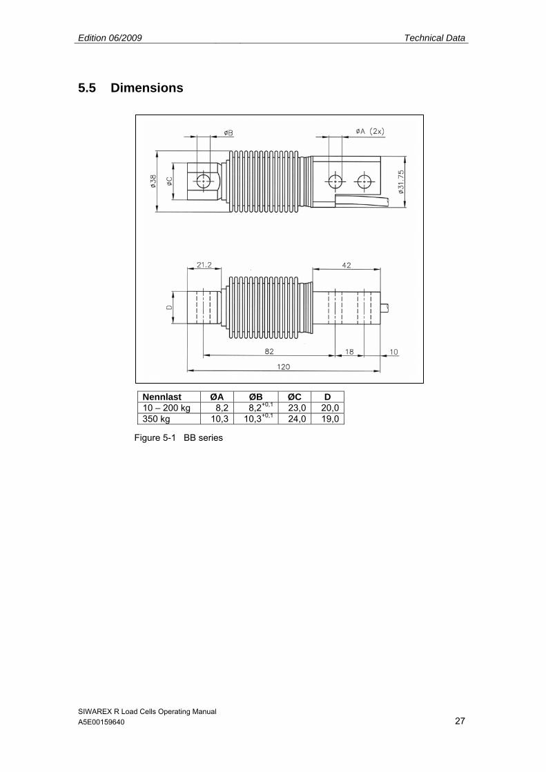
5.5 Dimensions
Nennlast ØA ØB ØC D 10 – 200 kg 8,2 8,2+0,1 23,0 20,0350 kg 10,3 10,3+0,1 24,0 19,0
Figure 5-1 BB series

Edition 06/2009 Technical Data
SIWAREX R Load Cells Operating Manual A5E00159640 28
Rated load A B C D E ØF G H J ØK ØL M 0,5 – 2 t 203,2 36,5 98,4 63,5 19,1 30,2+0,2 36,5 11,9 47,6 17,5H11 14 101,6 5 t 235,0 47,5 123,8 66,7 20,6 41,3+0,2 47,6 15,8 69,9 25,5H11 22 111,2
Figure 5-2 SB series
Edition 06/2009 Technical Data
SIWAREX R Load Cells Operating Manual A5E00159640 29
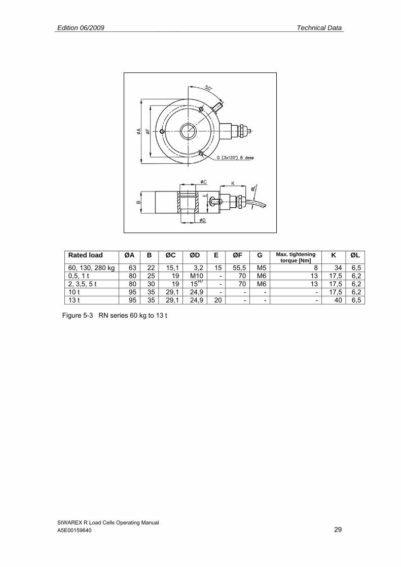
Rated load ØA B ØC ØD E ØF G Max. tightening torque [Nm]
K ØL
60, 130, 280 kg 63 22 15,1 3,2 15 55,5 M5 8 34 6,50,5, 1 t 80 25 19 M10 - 70 M6 13 17,5 6,22, 3,5, 5 t 80 30 19 15H7 - 70 M6 13 17,5 6,210 t 95 35 29,1 24,9 - - - - 17,5 6,213 t 95 35 29,1 24,9 20 - - - 40 6,5
Figure 5-3 RN series 60 kg to 13 t

Edition 06/2009 Technical Data
SIWAREX R Load Cells Operating Manual A5E00159640 30
Rated load ØA B ØC E 28 t 120 46 35,9 2560 t 140 62 47,9 34
Figure 5-4 RN series 28 und 60 t
Edition 06/2009 Technical Data
SIWAREX R Load Cells Operating Manual A5E00159640 31
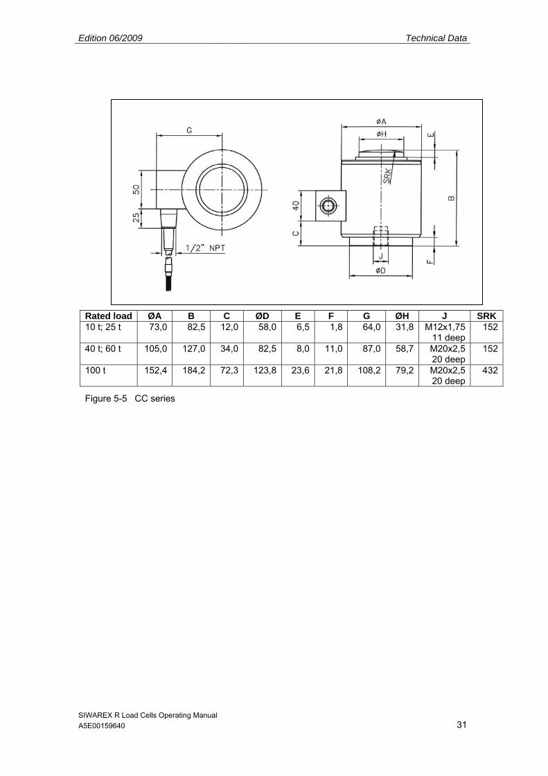
Rated load ØA B C ØD E F G ØH J SRK 10 t; 25 t 73,0 82,5 12,0 58,0 6,5 1,8 64,0 31,8 M12x1,75
11 deep152
40 t; 60 t 105,0 127,0 34,0 82,5 8,0 11,0 87,0 58,7 M20x2,5 20 deep
152
100 t 152,4 184,2 72,3 123,8 23,6 21,8 108,2 79,2 M20x2,5 20 deep
432
Figure 5-5 CC series

Edition 06/2009 Technical Data
SIWAREX R Load Cells Operating Manual A5E00159640 32
Rated load Ød ØD H K L SRA 2,8t 16,7 45 40 54 56 50 6 t 16,7 45 40 54 56 50 13 t 24,5 55 44 59 68 66 28 t 36 64 46 63,5 74 72 60 t 52,7 90 50 76,5 90 100 130 t 77,5 121 64 92 116 125 280 t 114 165 80 114 170 183
Figure 5-6 K series

Edition 06/2009 Technical Data
SIWAREX R Load Cells Operating Manual A5E00159640 33
See data sheet for dimensions of unlisted load cells.
Figure 5-7 SP series

SIWAREX R Load Cells Operating Manual A5E00159640 34
6 Ordering Data
BB series Verification capability to OIML R60 up to 3000 d, Connecting cable3 m4) (4-wire)
Order No.: 7MH4 103 - C 1 Nominal load: 10 kg 2 A 20 kg 2 D 50 kg 2 K 100 kg 3 A 200 kg 3 D 350 kg1) 3 G Explosion protection • Without 0 • With degree of protection EEx ib II C T6 for
connection to intrinsically-safe circuits 1
CC series Verification capability to OIML R60 up to 3000 d, Connecting cable (4-wire)
Order No.: 7MH4 106 - 1 connecting cable Nominal load: 10 t Length4): 10 m 5 A C 25 t 20 m 5 E C 40 t 20 m 5 H C 60 t 20 m 5 L C 100 t2) 20 m 6 A A Explosion protection • Without 0 • With degree of protection EEx ib II C T6 for
connection to intrinsically-safe circuits 1
Order No.: 7MH4 105 - C 1 Nominal load: 500 kg 3 K 1 t 4 A 2 t 4 D 5 t 4 K Explosion protection • Without 0 • With degree of protection EEx ib II C T6 for
connection to intrinsically-safe circuits 1
SB series Verification capability to OIML R60 up to 3000 d, Connecting cable5 m4) (4-wire)
Order No.: 7MH3 105 - C0 connecting cable Nominal load: 2,8 t Length4): 5 m 2 A 6 t 5 m 3 A 13 t 10 m 1 B 28 t 10 m 2 B 60 t 10 m 3 B 130 t 10 m 1 C 280 t 10 m 2 C
K series Accuracy class 0.2, Without explosion protection,connecting cable 3) (4-wire)
1) Mounting accessories on request. 2) Verification capability to OIML R60 up to 1000 d. 3) Cables heat-resistant: -60 °C to +180 °C. 4) Length tolerance: +/- 100 mm; cable length 20 m or more: +/- 300 mm. Furhter models of load cells on inquiry.
Order No.: 7MH5 101 - D 0 connecting cable Nominal load: 60 kg Length4): 3 m 2 Q 130 kg 3 m 3 D 280 kg 3 m 3 J 500 kg 3 m 3 P 1 t 3 m 4 A 2 t 5 m 4 G 3,5 t 5 m 4 L 5 t 5 m 4 P 10 t 5 m 5 A 13 t 10 m 5 D 28 t 10 m 5 J 60 t 15 m 5 Q Explosion protection • Without 0 • With degree of protection EEx ib II C T6 for
connection to intrinsically-safe circuits 1
RN series Verification capability to OIML R60 up to 3000 d, Connecting cable (4-wire)
SP series Verification capability to OIML R60 up to 3000 d, Connecting cable (6-wire)
Order No.: 7MH4 107 - C 0 Connection cable Nomnal load: 6 kg Length4): 7 m 1 L 12 kg 7 m 2 B Explosion protection • Without 0 • With degree off protection EEx ib II C T6 for
connection to intrinsically-safe circuits 1